fishing vessel hull design and towing resistance...
TRANSCRIPT
Zeszyty Naukowe 40(112) 27
Scientific Journals Zeszyty Naukowe Maritime University of Szczecin Akademia Morska w Szczecinie
2014, 40(112) pp. 27–30 ISSN 1733-8670
Fishing vessel hull design and towing resistance calculation by the CFD methods
Karol Sugalski
West Pomeranian University of Technology, Faculty of Marine Technology 71-065 Szczecin, al. Piastów 41, e-mail: [email protected]
Key words: fishing vessel, stern trawler, resistance calculation, computational fluid dynamics
Abstract Hull resistance and propulsion calculations are the basis of every ship design. In this paper, application of the
computational fluid dynamics are presented together with the results of towing resistance of the model of
stern trawler. The practical use of CFD in the preliminary vessels' design process were presented at the stern
trawler vessel type.All calculations had been performed in the free CFD software called OpenFOAM. This is
set of C++ programming language libraries, designed to solve Navier-Stokes equations.
Introduction
During preliminary design of a new vessel, with
respect to the ship-owner needs, naval architect
tries to find most optimal hull shape that fits all
demands, for example, minimal hull resistance for
a given velocity of the vessel. At the beginning
of the design process, hull resistance and needed
engine power are estimated by analytical equations,
after that, towing tank tests should be performed
but they are very expensive.
Nowadays, for hull shape, resistance and power
calculation the CFD (Computational Fluid Dynam-
ics ) methods are widely used. Results are accurate
and also confirmed by towing tank tests [1, 2, 3].
CFD methods are particularly useful for unusual
shaped vessels, or for those which analytical equa-
tions for resistance are inaccurate.
In this paper, the practical use of CFD in the
preliminary vessels' design process were presented
at the stern trawler vessel type. Towing resistance
of bare hull was calculated by using two phase vis-
cous flow. Wave system generated by the moving
hull was also obtained in the calculations.
All calculations were performed in the free CFD
software called OpenFOAM. This is set of C++
programming language libraries, designed to solve
Navier-Stokes equations. Mesh generators and
postprocessor are included in the software package.
Governing equations and fluid to hull influence
Influence of fluid to the rigid wall can be calcu-
lated with the so called Navier-Stokes equations
(2). They are also used to determine velocity field
and pressure inside the volume of moving fluid.
Combined with the continuity equation (1), the
Navier-Stokes equations, among all other applica-
tions allow to calculate hull resistance of the mov-
ing vessel. They are presented below [4].
0
i
i
x
V (1)
ij
i
i
i
j
ij
i
xx
Vv
x
pF
x
VV
t
V
21
(2)
where:
i, j = 1, 2, 3;
Vi,j – components of main velocity vector;
Fi – components of mass force vector;
– fluid density;
v – kinematics viscosity.
Navier-Stokes equations are the only choice
for dynamics of Newtonian fluids but they can’t
be solved in the turbulent case [4, 5]. When tur-
bulences are important, modified form of N–S
equations should be used. They are called Reynold
Karol Sugalski
28 Scientific Journals 40(112)
Averaged Navier Stokes Equations also known as
RANSE method [6]. It is shown below (3):
i
ij
i
j
jii
xF
x
VV
t
V
1 (3)
where ij is a tensor of mean stresses (4):
ij
i
j
j
iijij
x
V
x
VP
(4)
where:
ij – Kronecker delta;
P – pressure;
– dynamic viscosity;
ij – turbulent stress tensor.
Pressure and velocity field related to the hull
was calculated with the RANSE method. Men-
tioned equations needs some kind of space that
describes given experiment. This space is called the
numerical grid or mesh. Values of pressure and
velocity are calculated with the finite volume meth-
od. OpenFOAM is based on this method.
Concept of finite volume method is to discretize
governing equations, written in the integral form,
on the physical mesh describing given geometry.
Values of variables are stored in the cell centers [7].
In the turbulent case, RANSE equations do not
form a closed system. Adding additional equations
to close the system. Those equations comes from
the appropriate turbulence model.
Standard k- model [7] of turbulences was good
enough to the towing resistance problem. In the
flow separation region this model can be inaccurate
but overall resistance values are close to the exper-
imental data [1].
Hull geometry of the stern trawler
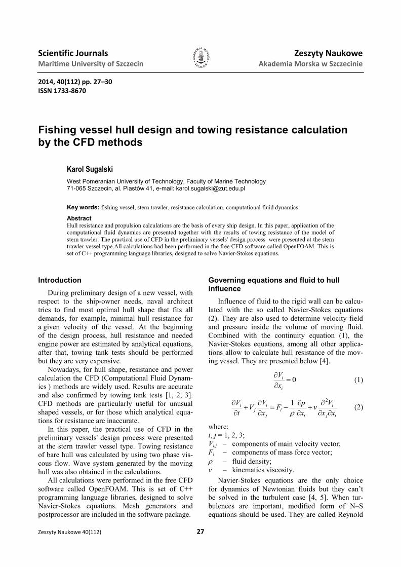
Towing resistance was calculated for the modi-
fied version of the B410 stern trawler. Simplified
general arrangement is shown in figure 1. Three-
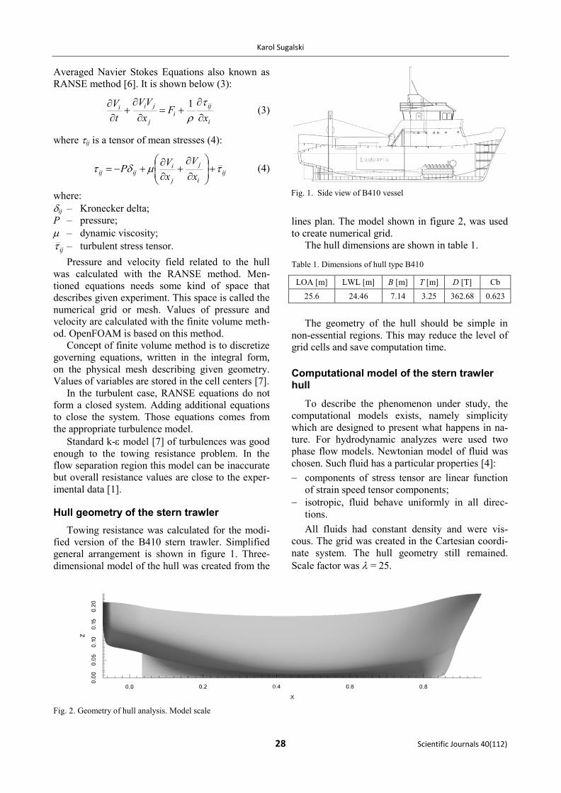
dimensional model of the hull was created from the
lines plan. The model shown in figure 2, was used
to create numerical grid.
The hull dimensions are shown in table 1.
Table 1. Dimensions of hull type B410
LOA [m] LWL [m] B [m] T [m] D [T] Cb
25.6 24.46 7.14 3.25 362.68 0.623
The geometry of the hull should be simple in
non-essential regions. This may reduce the level of
grid cells and save computation time.
Computational model of the stern trawler hull
To describe the phenomenon under study, the
computational models exists, namely simplicity
which are designed to present what happens in na-
ture. For hydrodynamic analyzes were used two
phase flow models. Newtonian model of fluid was
chosen. Such fluid has a particular properties [4]:
components of stress tensor are linear function
of strain speed tensor components;
isotropic, fluid behave uniformly in all direc-
tions.
All fluids had constant density and were vis-
cous. The grid was created in the Cartesian coordi-
nate system. The hull geometry still remained.
Scale factor was = 25.
Fig. 1. Side view of B410 vessel
Fig. 2. Geometry of hull analysis. Model scale
Fishing vessel hull design and towing resistance calculation by the CFD methods
Zeszyty Naukowe 40(112) 29
Appropriate boundary conditions should be used
to solve the Navier-Stokes equations. Those condi-
tions describes how the equations behaves on the
borders of the mesh. To avoid influence of bounda-
ry conditions to the solution, borders of the grid
should be far away from the geometry. The bounda-
ry conditions used in this paper are most common
and simple: rigid wall, symmetry plane, inlet and
outlet. Mathematical explanation of above bounda-
ry condition can be found in [8]. In OpenFOAM,
boundary conditions have to be defined for all
computed variables. Details of the implemented
boundary conditions can be found in [9].
Numerical grid is created from so called compu-
tational cells. The cells can have many different
shapes [5]. In OpenFOAM all cells are of hexahe-
dron type. In the vicinity of geometry, cells are
twisted and folded, by a meshing program, to fit the
shape of analyzed object.
Quality of the analyzed shape depends on the
number of cells. More cells give also better and
more accurate solution of governing equations.
Bare hull with no appendages was used for sim-
ulation. Three velocity cases were chosen. They are
shown in table 3. The hull was cut in the symmetry
plane to speed up calculations. In the domain two
fluids were modeled: water and air. Water level was
set to the draught of the vessel in the model scale.
Properties of the computational model shown in
table 2. The boundary conditions of the simulation
shown in table 4.
Table 2. Characteristics of the hull analysis model
Flow type Turbulent transient
Simulation time [s] 10
Air density [kg/m3] 1
Water density [kg/m3] 999
Kinematic viscosity of air[m2/s] 1.4810–5
Kinematic viscosity of water [m2/s] 1.1389610–6
Table 3. Velocities used in the hull analysis
Real scale
velocity [kn]
Model scale
velocity [m/s]
Froude
number
Reynold’s
number
8 0.823 0.265 706981.1
11 1.132 0.3653 972421.1
15 1.5433 0.4981 1325739.9
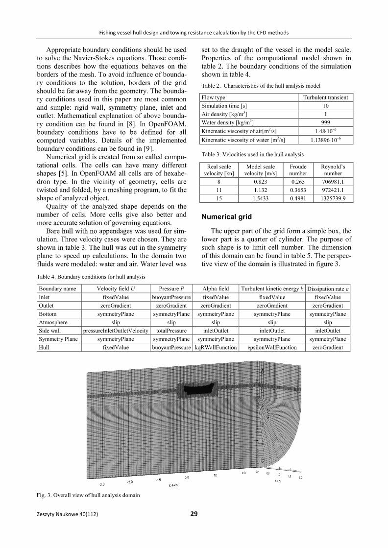
Numerical grid
The upper part of the grid form a simple box, the
lower part is a quarter of cylinder. The purpose of
such shape is to limit cell number. The dimension
of this domain can be found in table 5. The perspec-
tive view of the domain is illustrated in figure 3.
Table 4. Boundary conditions for hull analysis
Boundary name Velocity field U Pressure P Alpha field Turbulent kinetic energy k Dissipation rate
Inlet fixedValue buoyantPressure fixedValue fixedValue fixedValue
Outlet zeroGradient zeroGradient zeroGradient zeroGradient zeroGradient
Bottom symmetryPlane symmetryPlane symmetryPlane symmetryPlane symmetryPlane
Atmosphere slip slip slip slip slip
Side wall pressureInletOutletVelocity totalPressure inletOutlet inletOutlet inletOutlet
Symmetry Plane symmetryPlane symmetryPlane symmetryPlane symmetryPlane symmetryPlane
Hull fixedValue buoyantPressure kqRWallFunction epsilonWallFunction zeroGradient
Fig. 3. Overall view of hull analysis domain

Karol Sugalski
30 Scientific Journals 40(112)
Table 5. Dimensions of the hull analysis domain
Length of
domain on x-axis [m]
Length of
domain on y-axis [m]
Length of do-
main on z-axis [m]
Cell
number
6 2 3 1 245 506
Grid refinement visible in figure 3, in the free
surface region, allows to reproduce waves with
good accuracy.
Results of numerical computations
The results of towing resistance calculations are
shown in table 6. Resistance values are averaged
over time t (3, 10) of the simulation.
Table 6. Computed resistance of the bare hull
Velocity [m/s] Total resistance of bare hull [N]
0.823 1.03
1.132 2.729
1.5433 18.879
Calculated waves system shown in figures 4, 5
and 6.
Fig. 4. Wave pattern for velocity 0.823 m/s
Fig. 5. Wave pattern for velocity 1.132 m/s
Fig. 6. Wave pattern for velocity 1.5433 m/s
Conclusions
The towing resistance and waves system of the
model of stern trawler were calculated. Values of
resistance can be used to determine engine
power needed for contracted speed of the vessel.
In figures 5 and 6 change in the wave system can be
seen. This phenomenon occurs for high Froude
number. This may be proof of good accuracy of the
selected methods of calculation.
CFD can be useful tool for preliminary design
of ships. Many variants of the hull can be tested
before creating physical model for the towing tank
experiment.
References
1. SZELANGIEWICZ T., ABRAMOWSKI T.: Numerical analysis of
influence of ship hull form modification on ship resistance
and propulsion characteristics. Polish Maritime Research
16, 4, 2009.
2. Numerical analysis of influence of ship hull form modifica-
tion on ship resistance and propulsion characteristics. Part
II. Polish Maritime Research 17, 1, 2010.
3. SZELANGIEWICZ T., ABRAMOWSKI T., ŻELAZNY K.: Numeri-
cal analysis of effect of asymmetric stern of ship on its
screw propeller efficiency. Polish Maritime Research 17, 4,
2010.
4. GRYBOŚ R.: Podstawy Mechaniki Płynów. Wydawnictwo
Naukowe PWN, Warszawa 1998.
5. BLAZEK J.: Computational Fluid Dynamics: Principles and
applications. Second Edition. Elsevier, New York 2005.
6. OERTEL H.: Prandtl’s Essentials of Fluid Mechanics.
Springer, New York 2004.
7. FERZIGER J.H., PERIĆ M.: Computational Methods for Fluid
Dynamics. Springer, Berlin 2002.
8. ANDERSON J.D. JR.: Compoutational Fluid Dynamics.
McGraw-Hill Inc., New York.
9. ESI-OpenCFD. www.openfoam.org [online] ESI-Open-
CFD, 2014. http://www.openfoam.org/docs/cpp/.