fisher level instrument selection guide - pacific · pdf filelevel instruments product...
TRANSCRIPT
www.Fisher.com
D10
3219
X01
2
Fisher� Level Instrument Selection Guide
W8679
W8678
2500 SERIES CONTROLLER INCOMBINATION WITH A 249W SENSOR(L3 PNEUMATIC LEVEL CONTROLLER)
DLC3000 DIGITAL LEVEL CONTROLLER INCOMBINATION WITH A 249W SENSOR(DL3 DIGITAL LEVEL TRANSMITTER)
W8418-1
L2 LIQUID LEVEL CONTROLLER
W9331
L2sj LIQUID LEVEL CONTROLLER
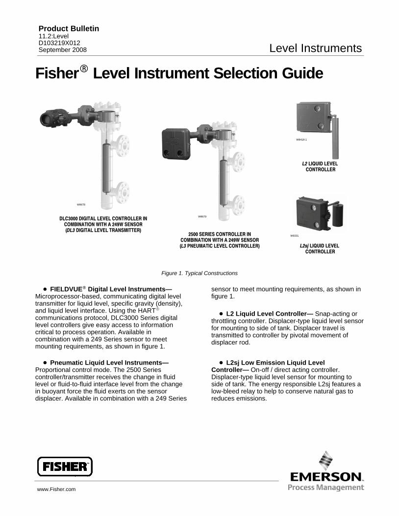
Figure 1. Typical Constructions
� FIELDVUE� Digital Level Instruments—Microprocessor-based, communicating digital leveltransmitter for liquid level, specific gravity (density),and liquid level interface. Using the HART�
communications protocol, DLC3000 Series digitallevel controllers give easy access to informationcritical to process operation. Available incombination with a 249 Series sensor to meetmounting requirements, as shown in figure 1.
� Pneumatic Liquid Level Instruments—Proportional control mode. The 2500 Seriescontroller/transmitter receives the change in fluidlevel or fluid-to-fluid interface level from the changein buoyant force the fluid exerts on the sensordisplacer. Available in combination with a 249 Series
sensor to meet mounting requirements, as shown infigure 1.
� L2 Liquid Level Controller— Snap-acting orthrottling controller. Displacer-type liquid level sensorfor mounting to side of tank. Displacer travel istransmitted to controller by pivotal movement ofdisplacer rod.
� L2sj Low Emission Liquid LevelController— On-off / direct acting controller.Displacer-type liquid level sensor for mounting toside of tank. The energy responsible L2sj features alow-bleed relay to help to conserve natural gas toreduces emissions.
Product Bulletin11.2:LevelD103219X012September 2008 Level Instruments
Level InstrumentsProduct Bulletin
11.2:LevelSeptember 2008
2
FIELDVUE� Digital Level Instruments
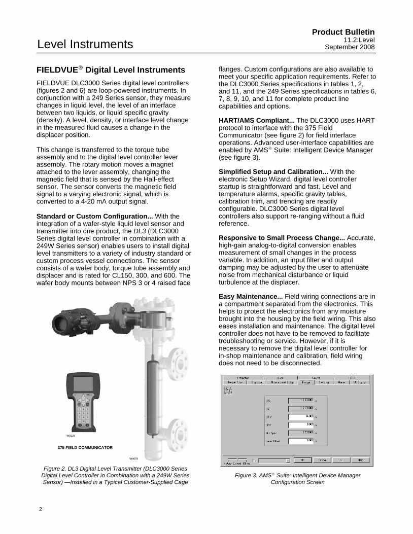
FIELDVUE DLC3000 Series digital level controllers(figures 2 and 6) are loop-powered instruments. Inconjunction with a 249 Series sensor, they measurechanges in liquid level, the level of an interfacebetween two liquids, or liquid specific gravity(density). A level, density, or interface level changein the measured fluid causes a change in thedisplacer position.
This change is transferred to the torque tubeassembly and to the digital level controller leverassembly. The rotary motion moves a magnetattached to the lever assembly, changing themagnetic field that is sensed by the Hall-effectsensor. The sensor converts the magnetic fieldsignal to a varying electronic signal, which isconverted to a 4-20 mA output signal.
Standard or Custom Configuration... With theintegration of a wafer-style liquid level sensor andtransmitter into one product, the DL3 (DLC3000Series digital level controller in combination with a249W Series sensor) enables users to install digitallevel transmitters to a variety of industry standard orcustom process vessel connections. The sensorconsists of a wafer body, torque tube assembly anddisplacer and is rated for CL150, 300, and 600. Thewafer body mounts between NPS 3 or 4 raised face
W8678
375 FIELD COMMUNICATOR
W9128
Figure 2. DL3 Digital Level Transmitter (DLC3000 SeriesDigital Level Controller in Combination with a 249W SeriesSensor) —Installed in a Typical Customer-Supplied Cage
flanges. Custom configurations are also available tomeet your specific application requirements. Refer tothe DLC3000 Series specifications in tables 1, 2,and 11, and the 249 Series specifications in tables 6,7, 8, 9, 10, and 11 for complete product linecapabilities and options.
HART/AMS Compliant... The DLC3000 uses HARTprotocol to interface with the 375 FieldCommunicator (see figure 2) for field interfaceoperations. Advanced user-interface capabilities areenabled by AMS� Suite: Intelligent Device Manager(see figure 3).
Simplified Setup and Calibration... With theelectronic Setup Wizard, digital level controllerstartup is straightforward and fast. Level andtemperature alarms, specific gravity tables,calibration trim, and trending are readilyconfigurable. DLC3000 Series digital levelcontrollers also support re-ranging without a fluidreference.
Responsive to Small Process Change... Accurate,high-gain analog-to-digital conversion enablesmeasurement of small changes in the processvariable. In addition, an input filter and outputdamping may be adjusted by the user to attenuatenoise from mechanical disturbance or liquidturbulence at the displacer.
Easy Maintenance... Field wiring connections are ina compartment separated from the electronics. Thishelps to protect the electronics from any moisturebrought into the housing by the field wiring. This alsoeases installation and maintenance. The digital levelcontroller does not have to be removed to facilitatetroubleshooting or service. However, if it isnecessary to remove the digital level controller forin-shop maintenance and calibration, field wiringdoes not need to be disconnected.
Figure 3. AMS� Suite: Intelligent Device ManagerConfiguration Screen
Level InstrumentsProduct Bulletin11.2:LevelSeptember 2008
3
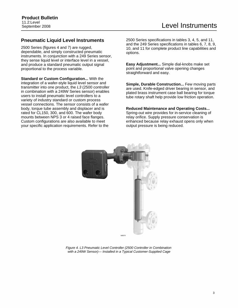
Pneumatic Liquid Level Instruments2500 Series (figures 4 and 7) are rugged,dependable, and simply constructed pneumaticinstruments. In conjunction with a 249 Series sensor,they sense liquid level or interface level in a vessel,and produce a standard pneumatic output signalproportional to the process variable.
Standard or Custom Configuration... With theintegration of a wafer-style liquid level sensor andtransmitter into one product, the L3 (2500 controllerin combination with a 249W Series sensor) enablesusers to install pneumatic level controllers to avariety of industry standard or custom processvessel connections. The sensor consists of a waferbody, torque tube assembly and displacer and israted for CL150, 300, and 600. The wafer bodymounts between NPS 3 or 4 raised face flanges.Custom configurations are also available to meetyour specific application requirements. Refer to the
2500 Series specifications in tables 3, 4, 5, and 11,and the 249 Series specifications in tables 6, 7, 8, 9,10, and 11 for complete product line capabilities andoptions.
Easy Adjustment... Simple dial-knobs make setpoint and proportional valve opening changesstraightforward and easy.
Simple, Durable Construction... Few moving partsare used. Knife-edged driver bearing in sensor, andplated brass instrument case ball bearing for torquetube rotary shaft help provide low friction operation.
Reduced Maintenance and Operating Costs...Spring-out wire provides for in-service cleaning ofrelay orifice. Supply pressure conservation isenhanced because relay exhaust opens only whenoutput pressure is being reduced.
W8679
Figure 4. L3 Pneumatic Level Controller (2500 Controller in Combination with a 249W Sensor)— Installed in a Typical Customer-Supplied Cage
Level InstrumentsProduct Bulletin
11.2:LevelSeptember 2008
4
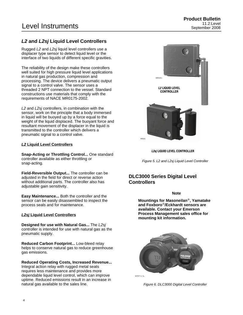
L2 and L2sj Liquid Level Controllers
Rugged L2 and L2sj liquid level controllers use adisplacer type sensor to detect liquid level or theinterface of two liquids of different specific gravities.
The reliability of the design make these controllerswell suited for high pressure liquid level applicationsin natural gas production, compression andprocessing. The device delivers a pneumatic outputsignal to a control valve. The sensor uses athreaded 2 NPT connection to the vessel. Standardconstructions use materials that comply with therequirements of NACE MR0175-2002.
L2 and L2sj controllers, in combination with thesensor, work on the principle that a body immersedin liquid will be buoyed up by a force equal to theweight of the liquid displaced. The buoyant force andresultant movement of the displacer in the liquid istransmitted to the controller which delivers apneumatic signal to a control valve.
L2 Liquid Level Controllers
Snap-Acting or Throttling Control... One standardcontroller available as either throttling orsnap-acting.
Field-Reversible Output... The controller can beadjusted in the field for direct or reverse actionwithout additional parts. The controller also hasadjustable gain sensitivity.
Easy Maintenance... Both the controller and thesensor can be easily disassembled to inspect theprocess seals and for maintenance.
L2sj Liquid Level Controllers
Designed for use with Natural Gas... The L2sjcontroller is intended for use with natural gas as thepneumatic supply.
Reduced Carbon Footprint... Low-bleed relayhelps to conserve natural gas to reduce greenhousegas emissions.
Reduced Operating Costs, Increased Revenue...Integral action relay with rugged metal seatsrequires less maintenance and provides moredependable liquid level control, which can improveuptime. Reduced emissions result in an increase innatural gas available to the sales line.
W8418-1
L2 LIQUID LEVELCONTROLLER
L2sj LIQUID LEVEL CONTROLLER
W9331
Figure 5. L2 and L2sj Liquid Level Controller
DLC3000 Series Digital LevelControllers
Note
Mountings for Masoneilan�, Yamatakeand Foxboro�/Eckhardt sensors areavailable. Contact your EmersonProcess Management sales office formounting kit information.
W7977-1 / IL
Figure 6. DLC3000 Digital Level Controller
Level InstrumentsProduct Bulletin11.2:LevelSeptember 2008
5
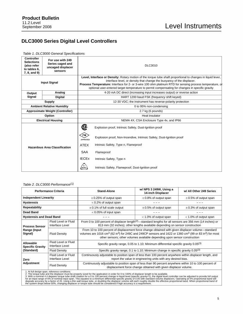
DLC3000 Series Digital Level Controllers
Table 1. DLC3000 General SpecificationsControllerSelections(also referto tables 6,7, 8, and 9)
For use with 249Series caged and
uncaged displacersensors
DLC3010
Input Signal
Level, Interface or Density: Rotary motion of the torque tube shaft proportional to changes in liquid lever,interface level, or density that change the buoyancy of the displacer.
Process Temperature: Interface for 2- or 3-wire 100 ohm platinum RTD for sensing process temperature, oroptional user-entered target temperature to permit compensating for changes in specific gravity
OutputSignal
Analog 4-20 mA DC direct (increasing input increases output) or reverse action
Digital HART 1200 baud FSK (frequency shift keyed)
Supply 12-30 VDC; the instrument has reverse-polarity protection
Ambient Relative Humidity 0 to 95% non-condensing
Approximate Weight (Controller) 2.7 kg (6 pounds)
Option Heat insulator
Electrical Housing NEMA 4X, CSA Enclosure Type 4x, and IP66
Hazardous Area Classification
Explosion proof, Intrinsic Safety, Dust-Ignition proof
APPROVEDExplosion proof, Non-Incendive, Intrinsic Safety, Dust-Ignition proof
Intrinsic Safety, Type n, FlameproofATEX
SAA Flameproof
IECEx Intrinsic Safety, Type n
Intrinsic Safety, Flameproof, Dust-Ignition proof
Table 2. DLC3000 Performance(1)
Performance Criteria Stand-Alone w/ NPS 3 249W, Using a14-inch Displacer
w/ All Other 249 Series
Independent Linearity �0.25% of output span �0.8% of output span �0.5% of output span
Hysteresis < 0.2% of output span − − − − − −
Repeatability �0.1% of full scale output �0.5% of output span �0.3% of output span
Dead Band < 0.05% of input span − − − − − −
Hysteresis and Dead Band − − − < 1.0% of output span < 1.0% of output span
Process SensorRange (InputSignal)
Fluid Level or FluidInterface Level
From 0 to 100 percent of displacer length(2)—standard lengths for all sensors are 356 mm (14 inches) or813 mm (32 inches); other lengths available depending on sensor construction
Fluid DensityFrom 10 to 100 percent of displacement force change obtained with given displacer volume—standard
volumes are 1016 cm3 (62 in3) for 249C and 249CP sensors and 1622 or 1360 cm3 (99 or 83 in3) for mostother sensors; other volumes available depending upon sensor construction
AllowableSpecific Gravity(Standard)
Fluid Level or FluidInterface Level
Specific gravity range, 0.05 to 1.10; Minimum differential specific gravity 0.05(3)
Fluid Density Specific gravity range, 0.1 to 1.10; Minimum change in specific gravity 0.05(3)
ZeroAdjustment
Fluid Level or FluidInterface Level
Continuously adjustable to position span of less than 100 percent anywhere within displacer length, andreport the value in engineering units with any desired bias.
Fluid DensityContinuously adjustable to position span of less than 90 percent anywhere within 10 to 100 percent of
displacement force change obtained with given displacer volume.1. At full design span, reference conditions.2. The torque tube and the displacer must be properly sized for the application in order for 0 to 100% of displacer length to be available.3. With a nominal 4.4 degrees torque tube shaft rotation for a 0 to 100 percent change in liquid level (specific gravity=1), the digital level controller can be adjusted to provide full outputfor an input range of 5% of nominal input span. This equates to a minimum differential specific gravity of 0.05 with standard volume displacers. Operating at 5% proportional band willdegrade accuracy by a factor of 20. Using a thin wall torque tube, or doubling the displacer volume will each roughly double the effective proportional band. When proportional band ofthe system drops below 50%, changing displacer or torque tube should be considered if high accuracy is a requirement.
Level InstrumentsProduct Bulletin
11.2:LevelSeptember 2008
6
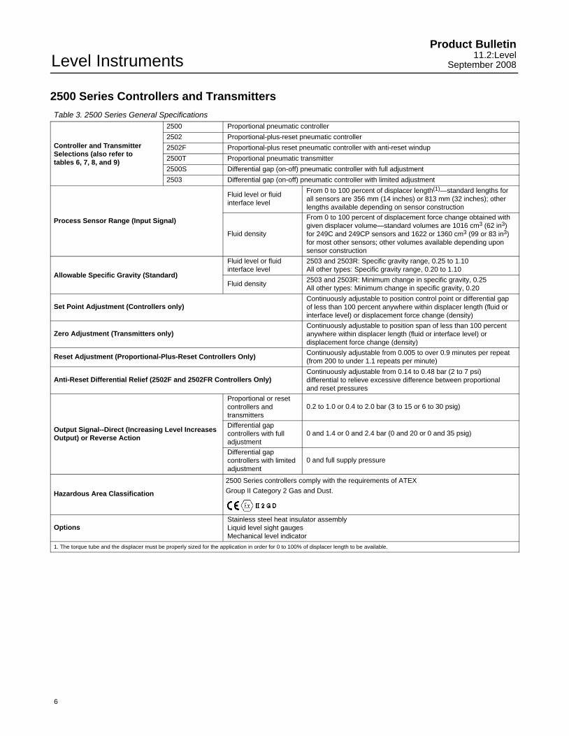
2500 Series Controllers and Transmitters
Table 3. 2500 Series General Specifications
Controller and TransmitterSelections (also refer to tables 6, 7, 8, and 9)
2500 Proportional pneumatic controller
2502 Proportional-plus-reset pneumatic controller
2502F Proportional-plus reset pneumatic controller with anti-reset windup
2500T Proportional pneumatic transmitter
2500S Differential gap (on-off) pneumatic controller with full adjustment
2503 Differential gap (on-off) pneumatic controller with limited adjustment
Process Sensor Range (Input Signal)
Fluid level or fluidinterface level
From 0 to 100 percent of displacer length(1)—standard lengths forall sensors are 356 mm (14 inches) or 813 mm (32 inches); otherlengths available depending on sensor construction
Fluid density
From 0 to 100 percent of displacement force change obtained withgiven displacer volume—standard volumes are 1016 cm3 (62 in3)for 249C and 249CP sensors and 1622 or 1360 cm3 (99 or 83 in3)for most other sensors; other volumes available depending uponsensor construction
Allowable Specific Gravity (Standard)
Fluid level or fluidinterface level
2503 and 2503R: Specific gravity range, 0.25 to 1.10All other types: Specific gravity range, 0.20 to 1.10
Fluid density 2503 and 2503R: Minimum change in specific gravity, 0.25All other types: Minimum change in specific gravity, 0.20
Set Point Adjustment (Controllers only)Continuously adjustable to position control point or differential gap of less than 100 percent anywhere within displacer length (fluid orinterface level) or displacement force change (density)
Zero Adjustment (Transmitters only)Continuously adjustable to position span of less than 100 percentanywhere within displacer length (fluid or interface level) ordisplacement force change (density)
Reset Adjustment (Proportional-Plus-Reset Controllers Only) Continuously adjustable from 0.005 to over 0.9 minutes per repeat(from 200 to under 1.1 repeats per minute)
Anti-Reset Differential Relief (2502F and 2502FR Controllers Only)Continuously adjustable from 0.14 to 0.48 bar (2 to 7 psi) differential to relieve excessive difference between proportional and reset pressures
Output Signal--Direct (Increasing Level IncreasesOutput) or Reverse Action
Proportional or resetcontrollers andtransmitters
0.2 to 1.0 or 0.4 to 2.0 bar (3 to 15 or 6 to 30 psig)
Differential gapcontrollers with fulladjustment
0 and 1.4 or 0 and 2.4 bar (0 and 20 or 0 and 35 psig)
Differential gapcontrollers with limitedadjustment
0 and full supply pressure
Hazardous Area Classification
2500 Series controllers comply with the requirements of ATEX
Group II Category 2 Gas and Dust.
OptionsStainless steel heat insulator assemblyLiquid level sight gaugesMechanical level indicator
1. The torque tube and the displacer must be properly sized for the application in order for 0 to 100% of displacer length to be available.
Level InstrumentsProduct Bulletin11.2:LevelSeptember 2008
7
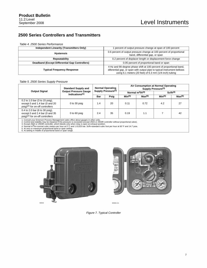
2500 Series Controllers and Transmitters
Table 4. 2500 Series PerformanceIndependent Linearity (Transmitters Only) 1 percent of output pressure change at span of 100 percent
Hysteresis 0.6 percent of output pressure change at 100 percent of proportionalband, differential gap, or span
Repeatability 0.2 percent of displacer length or displacement force change
Deadband (Except Differential Gap Controllers) 0.05 percent of proportional band or span
Typical Frequency Response4 Hz and 90-degree phase shift at 100 percent of proportional band,diferential gap, or span with output pipe to typical instrument bellows
using 6.1 meters (20 feet) of 6.3 mm (1/4-inch) tubing
Table 5. 2500 Series Supply Pressure
Output SignalStandard Supply and
Output Pressure GaugeIndications(1)
Normal OperatingSupply Pressure(2)
Air Consumption at Normal Operating Supply Pressure(3)
Normal m3/h(4) Scfh(4)
Bar Psig Min(5) Max(6) Min(5) Max(6)
0.2 to 1.0 bar (3 to 15 psig),except 0 and 1.4 bar (0 and 20psig)(2) for on-off controllers
0 to 30 psig 1.4 20 0.11 0.72 4.2 27
0.4 to 2.0 bar (6 to 30 psig),except 0 and 2.4 bar (0 and 35psig)(2) for on-off controllers
0 to 60 psig 2.4 35 0.19 1.1 7 42
1. Consult your Emerson Process Management sales office about gauges in other units.2. Control and stability may be impaired if this pressure is exceeded (except 2503 or 2503R controller without proportional valve).3. Except 2503 or 2503R controller, which bleeds only when relay is open at exhaust position.4. Normal m3/hr=normal cubic meters per hour at 0�C and 1.01325 bar. Scfh=standard cubic foot per hour at 60�F and 14.7 psia.5. At zero or maximum proportional band or span setting.6. At setting in middle of proportional band or span range.
W0656-1/ILW8333
Figure 7. Typical Controller
Level InstrumentsProduct Bulletin
11.2:LevelSeptember 2008
8
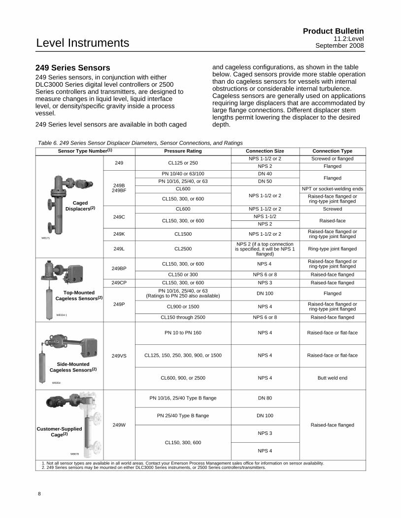
249 Series Sensors249 Series sensors, in conjunction with eitherDLC3000 Series digital level controllers or 2500Series controllers and transmitters, are designed tomeasure changes in liquid level, liquid interfacelevel, or density/specific gravity inside a processvessel.
249 Series level sensors are available in both caged
and cageless configurations, as shown in the tablebelow. Caged sensors provide more stable operationthan do cageless sensors for vessels with internalobstructions or considerable internal turbulence.Cageless sensors are generally used on applicationsrequiring large displacers that are accommodated bylarge flange connections. Different displacer stemlengths permit lowering the displacer to the desireddepth.
Table 6. 249 Series Sensor Displacer Diameters, Sensor Connections, and RatingsSensor Type Number(1) Pressure Rating Connection Size Connection Type
CagedDisplacers(2)
W8171
249 CL125 or 250NPS 1-1/2 or 2 Screwed or flanged
NPS 2 Flanged
249B249BF
PN 10/40 or 63/100 DN 40Flanged
PN 10/16, 25/40, or 63 DN 50
CL600NPS 1-1/2 or 2
NPT or socket-welding ends
CL150, 300, or 600 Raised-face flanged orring-type joint flanged
249C
CL600 NPS 1-1/2 or 2 Screwed
CL150, 300, or 600NPS 1-1/2
Raised-faceNPS 2
249K CL1500 NPS 1-1/2 or 2 Raised-face flanged orring-type joint flanged
249L CL2500NPS 2 (if a top connection
is specified, it will be NPS 1flanged)
Ring-type joint flanged
Top-MountedCageless Sensors(2)
W8334-1
249BPCL150, 300, or 600 NPS 4 Raised-face flanged or
ring-type joint flanged
CL150 or 300 NPS 6 or 8 Raised-face flanged
249CP CL150, 300, or 600 NPS 3 Raised-face flanged
249P
PN 10/16, 25/40, or 63(Ratings to PN 250 also available) DN 100 Flanged
CL900 or 1500 NPS 4 Raised-face flanged orring-type joint flanged
CL150 through 2500 NPS 6 or 8 Raised-face flanged
Side-MountedCageless Sensors(2)
W9354
249VS
PN 10 to PN 160 NPS 4 Raised-face or flat-face
CL125, 150, 250, 300, 900, or 1500 NPS 4 Raised-face or flat-face
CL600, 900, or 2500 NPS 4 Butt weld end
Customer-SuppliedCage(2)
W8678
249W
PN 10/16, 25/40 Type B flange DN 80
Raised-face flanged
PN 25/40 Type B flange DN 100
CL150, 300, 600
NPS 3
NPS 4
1. Not all sensor types are available in all world areas. Contact your Emerson Process Management sales office for information on sensor availability.2. 249 Series sensors may be mounted on either DLC3000 Series instruments, or 2500 Series controllers/transmitters.
Level InstrumentsProduct Bulletin11.2:LevelSeptember 2008
9
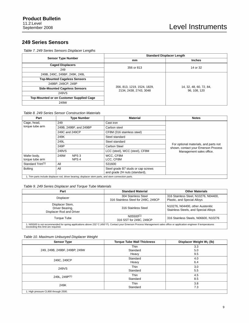
249 Series Sensors
Table 7. 249 Series Sensors Displacer Lengths
Sensor Type NumberStandard Displacer Length
mm Inches
Caged Displacers356 or 813 14 or 32
249
249B, 249C, 249BF, 249K, 249L
356, 813, 1219, 1524, 1829,2134, 2438, 2743, 3048
14, 32, 48, 60, 72, 84,96, 108, 120
Top-Mounted Cageless Sensors
249BP, 249CP, 249P
Side-Mounted Cageless Sensors
249VS
Top-Mounted or on Customer Supplied Cage
249W
Table 8. 249 Series Sensor Construction MaterialsPart Type Number Material Notes
Cage, head,torque tube arm
249 Cast iron
For optional materials, and parts notshown, contact your Emerson Process
Management sales office.
249B, 249BF, and 249BP Carbon steel
249C and 249CP CF8M (316 stainless steel)
249K Steel standard
249L Steel standard
249P Carbon Steel
249VS LCC (steel), WCC (steel), CF8M
Wafer body,torque tube arm
249W NPS 3NPS 4
WCC, CF8MLCC, CF8M
Standard Trim(1) All S31600
Bolting All Steel grade B7 studs or cap screws and grade 2H nuts (standard),
1. Trim parts include displacer rod, driver bearing; displacer stem parts, and stem connection parts.
Table 9. 249 Series Displacer and Torque Tube MaterialsPart Standard Material Other Materials
Displacer 304 Stainless Steel316 Stainless Steel for 249C, 249CP
316 Stainless Steel, N10276, N04400,Plastic, and Special Alloys
Displacer Stem,Driver Bearing,
Displacer Rod and Driver316 Stainless Steel N10276, N04400, other Austenitic
Stainless Steels, and Special Alloys
Torque Tube N05500(1)
316 SST for 249C, 249CP316 Stainless Steels, N06600, N10276
1. N05500 is not recommended for spring applications above 232�C (450�F). Contact your Emerson Process Management sales office or application engineer if temperaturesexceeding this limit are required.
Table 10. Maximum Unbuoyed Displacer WeightSensor Type Torque Tube Wall Thickness Displacer Weight WT (lb)
249, 249B, 249BF, 249BP, 249WThin
StandardHeavy
3.35.09.5
249C, 249CP StandardHeavy
4.06.4
249VS ThinStandard
3.05.5
249L, 249P(1) ThinStandard
4.58.5
249K ThinStandard
3.87.3
1. High pressure CL900 through 2500.
Level InstrumentsProduct Bulletin
11.2:LevelSeptember 2008
10
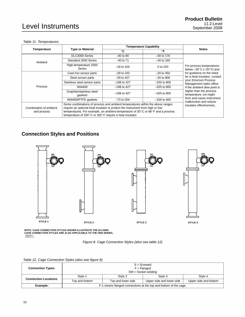
Table 11. Temperatures
Temperature Type or MaterialTemperature Capability
Notes�C �F
Ambient
DLC3000 Series –40 to 80 –40 to 176
For process temperaturesbelow −29�C (−20�F) andfor guidance on the needfor a heat insulator, contactyour Emerson ProcessManagement sales office.If the ambient dew point ishigher than the processtemperature, ice mightform and cause instrumentmalfunction and reduceinsulator effectiveness.
Standard 2500 Series −40 to 71 −40 to 160
High-temperature 2500Series
−18 to 104 0 to 220
Process
Cast iron sensor parts –29 to 232 –20 to 450
Steel sensor parts –29 to 427 –20 to 800
Stainless steel sensor parts –198 to 427 –325 to 800
N04400 –198 to 427 –325 to 800
Graphite/stainless steelgaskets
–198 to 427 –325 to 800
N04400/PTFE gaskets –73 to 204 –100 to 400
Combination of ambient and process
Some combinations of process and ambient temperatures within the above rangesrequire an optional heat insulator to protect the instrument from high or lowtemperatures. For example, an ambient temperature of 30�C or 86�F and a processtemperature of 200�C or 392�F require a heat insulator.
Connection Styles and Positions
STYLE 1 STYLE 2 STYLE 3 STYLE 4
28B5536-1B1820-2 / IL
NOTE: CAGE CONNECTION STYLES SHOWN ILLUSTRATE THE DLC3000.CAGE CONNECTION STYLES ARE ALSO APPLICABLE TO THE 2500 SERIES.
Figure 8. Cage Connection Styles (also see table 12)
Table 12. Cage Connection Styles (also see figure 8)
Connection Types:S = ScrewedF = Flanged
SW = Socket welding
Connection Locations:Style 1 Style 2 Style 3 Style 4
Top and bottom Top and lower side Upper side and lower side Upper side and bottom
Example: F-1 means flanged connections at the top and bottom of the cage.
Level InstrumentsProduct Bulletin11.2:LevelSeptember 2008
11
8
24
6
3
7
1
5 11
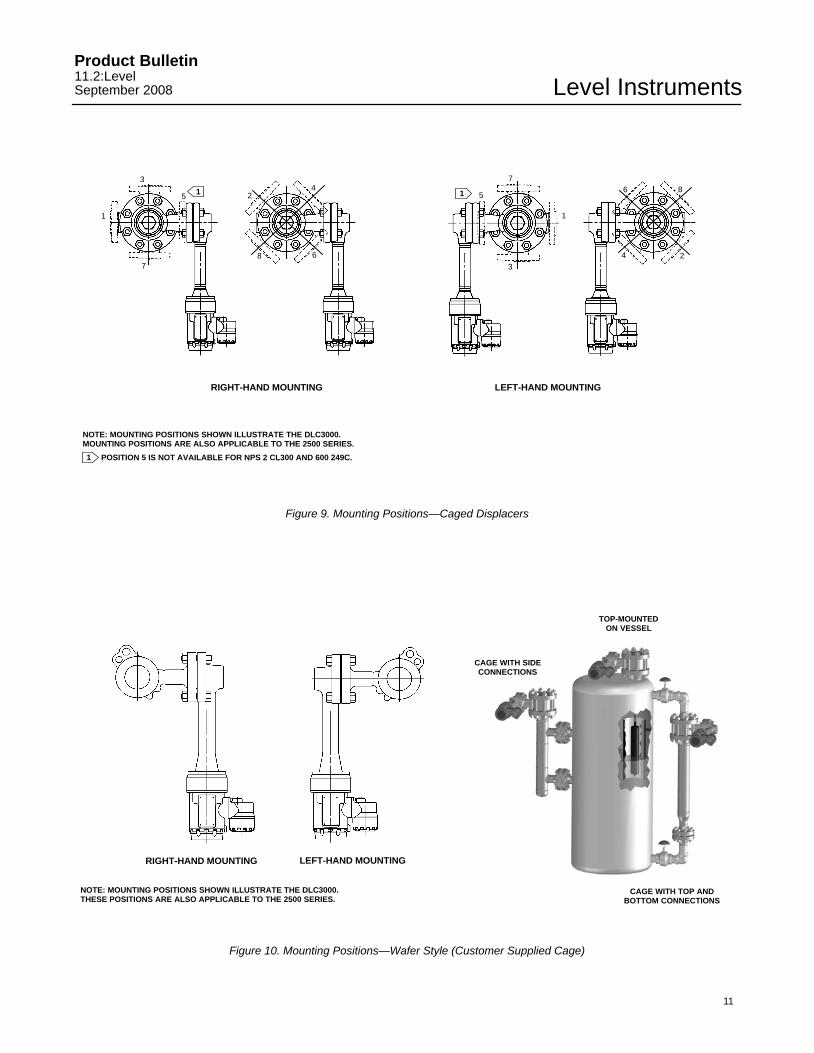
1 POSITION 5 IS NOT AVAILABLE FOR NPS 2 CL300 AND 600 249C.
8
24
6
1
3
7
5
RIGHT-HAND MOUNTING LEFT-HAND MOUNTING
NOTE: MOUNTING POSITIONS SHOWN ILLUSTRATE THE DLC3000.MOUNTING POSITIONS ARE ALSO APPLICABLE TO THE 2500 SERIES.
Figure 9. Mounting Positions—Caged Displacers
CAGE WITH SIDECONNECTIONS
TOP-MOUNTEDON VESSEL
CAGE WITH TOP ANDBOTTOM CONNECTIONS
RIGHT-HAND MOUNTING LEFT-HAND MOUNTING
NOTE: MOUNTING POSITIONS SHOWN ILLUSTRATE THE DLC3000.THESE POSITIONS ARE ALSO APPLICABLE TO THE 2500 SERIES.
Figure 10. Mounting Positions—Wafer Style (Customer Supplied Cage)
Level InstrumentsProduct Bulletin
11.2:LevelSeptember 2008
12
Related DocumentsOther documents containing information related tolevel instruments include:
� FIELDVUE� DLC3000 Series Digital LevelControllers (Bulletin 11.2:DLC3000)
� DL3 Digital Level Transmitter (Bulletin11.2:DL3)
� 2500-249 Series Pneumatic Controllers andTransmitters (Bulletin 34.2:2500)
� L3 Pneumatic Level Controller (Bulletin34.2:L3)
� L2 Liquid Level Controller (Bulletin 34.2:L2)
� L2sj Liquid Level Controller (Bulletin 34.2:L2sj)
Note
Neither Emerson, Emerson ProcessManagement, nor any of their affiliatedentities assumes responsibility for theselection, use, or maintenance of anyproduct. Responsibility for theselection, use, and maintenance of anyproduct remains with the purchaserand end-user.
Emerson Process ManagementMarshalltown, Iowa 50158 USASorocaba, 18087 BrazilChatham, Kent ME4 4QZ UKDubai, United Arab EmiratesSingapore 128461 Singapore
�Fisher Controls International LLC 2005, 2008; All Rights Reserved
www.Fisher.com
The contents of this publication are presented for informational purposes only, and while every effort has been made to ensure their accuracy, they arenot to be construed as warranties or guarantees, express or implied, regarding the products or services described herein or their use or applicability.All sales are governed by our terms and conditions, which are available upon request. We reserve the right to modify or improve the designs orspecifications of such products at any time without notice. Neither Emerson, Emerson Process Management, nor any of their affiliated entities assumesresponsibility for the selection, use or maintenance of any product. Responsibility for proper selection, use, and maintenance of any product remainssolely with the purchaser and end-user.
Fisher, FIELDVUE, and AMS are marks owned by one of the companies in the Emerson Process Management business division of EmersonElectric Co. Emerson Process Management, Emerson, and the Emerson logo are trademarks and service marks of Emerson Electric Co. HART isa mark owned by the HART Communication Foundation. All other marks are the property of their respective owners.