first notice safety notice 170012 - constant...
TRANSCRIPT

Terex Aerial Work Platforms, 6464 185th Ave NE Redmond WA 98073, Ph: 800-536-1800, 425-881-1800
1 of 2
First Notice
Safety Notice 170012 Mandatory Action Required North America
Asia-Pacific South America
Date: July 21, 2017
Models and Serial Numbers Affected: SX-150:
SX-180:
SX15015H-101 to 161 SX15016H-162 to 228 SX150H-500 to 501
SX18014-101 to 196 SX18015-197 to 313 SX18016-314 to 317 SX18016H-318 to 360 SX180H-600 to 602
Subject: Wear Pads
Allowable Hours: 20 hours
Issue:
Genie Industries has found that weld debris in the boom tubes could lead to premature and excessive wear of the upper wear pads. This excessive wear can lead to potential damage to the boom tubes and could cause the platform to drop.
Action(s) Required:
1 Locate the affected machines referenced above within your fleet.
2 Using the table below, order the appropriate kit to replace the wear pads on your machine.
Model Kit PN
SX-150 1280093GT
SX-180 1280092GT
Completion of this Safety Notice must be done as soon as possible but no later than 30 days from receipt of the kit.
3 Fill out and sign the completion form included in this Safety Notice or attached to the installation instructions included in the kit and fax or email to Terex AWP Warranty Department. This will serve as verification that you have completed Safety Notice 170012.
Continued Use Instructions:
All machine operators and users must be notified of these continued use requirements.
The affected machines may remain in service until this Safety Notice is completed, provided that inspection for wear pads is included as part of the pre-operation inspections outlined in the machine's Operator's Manual.

Terex Aerial Work Platforms, 6464 185th Ave NE Redmond WA 98073, Ph: 800-536-1800, 425-881-1800
2 of 2
First Notice
Safety Notice 170012 Mandatory Action Required North America
To order parts:
Machine owners with a valid Genie account can contact the Terex AWP Parts Department to place an order through one of the following:
Genie Website: https://www.gogenielift.com/default.aspxFax: 1-888-274-6192 Phone: 1-800-536-1800
Machine owners without a valid Genie account can contact their nearest Terex AWP dealership or Terex AWP Service Centers for assistance. Search for your nearest Terex AWP dealership by visiting our website at:
http://www.genielift.com/dealersearch/
Warranty:
The labor and travel miles required to perform this Safety Notice are covered under the provisions of our LIMITED PRODUCT WARRANTY statement. Warranty claims can be submitted online, by paper claims, fax or email. If you need more information about filing a warranty claim, please contact Terex AWP Warranty Department at:
Email (North America): [email protected]
Email (Asia-Pacific): [email protected]
Email (all others): [email protected]
United States: + 1-800-536-1800
Canada: + 1-425-881-1800
Asia-Pacific: + 86-21-347028555
South America (except Brazil): + 56-9-6431-2110
All other locations: + 1-425-881-1800
Genie and local industry standards (e.g. ANSI, CSA) requires that the seller of a Genie machine report to Genie the model and serial number of each machine sold, as well as the name, address, and telephone number of the new owner, within 60 days of the sale. Use the Owner Update Form attached to the bulletin to indicate the new location or status of any of your machines. You may also visit our website to register your machine.
Machine Registration_ANSI http://www.genielift.com/en/service-support/product-registration/index.htm
Genie, OSHA and local industry standards, also require that the manufacturer’s Safety Notice be completed. It is your responsibility to communicate this important information to all machine owners and applicable branches. If you require additional copies of this Safety Notice or have any questions, please contact Genie Product Support at:
United States: + 1-800-536-1800
Canada: + 1-425-881-1800
Asia-Pacific: + 86-21-347028555
South America (except Brazil): + 56-9-6431-2110
All other locations: + 1-425-881-1800
Enclosures:
Customer Machine List
New Owner Update Form NORTH AMERICA
Terex Aerial Work Platforms, 6464 185th Ave NE Redmond WA 98073, Ph: 800-536-1800, 425-881-1800
170012 Safety Notice
First Notice
Mandatory Action Required

Safety Notice 170012
New Owner Update Form (for updating machine owner information only)
Genie and ANSI requires that the seller of a Genie machine report to Genie the model and serial number of each machine sold, as well as the name, address, and telephone number of the new owner, within 60 days of the sale.
If you have sold a machine, list new owner's name, address and phone number, for each machine. List complete model and serial number (ex. SX15015H-139, SX18016H-439).
New Owner Information:
Machine 1 Machine 2 Machine 3
Model*
Serial Number *
Owner Name*
Address 1*
Address 2
City/State/Zip*
Phone Number*
Contact Person
* Required fields
Seller Information:
Date:
Company Name:
Account #:
Address:
(street):
(city):
(state, zip code) :
Phone #:
List any machines that could not be inspected or repaired because of the following:
Model & Serial Number Scrapped Exported Stolen Other (explain)
- - - -
- - - -
- - - -
- - - -
Fax to: United States: 1 877-738-7530 Latin America: + 55 11 3246-9760
Canada: 1 425-498-7530 Central America: + 1 425 498 7530
Mexico: 1 425-498-7530 Asia-Pacific: + 1 425 498 7530
Carribean: + 1 425 498 7530 All other locations: + 1 425 498 7530

Installation Instructions
Installation Instructions Wear Pad Replacement
SX-150
SX-180
Part No. 1278665GT Rev D

Instructions Rev D
Introduction
2 Installation Instructions Part No. 1278665GT
Introduction Introduction
Observe and Obey: This procedure shall be completed by a person
trained and qualified on the repair of this machine.
Immediately tag and remove from service a damaged or malfunctioning machine.
Repair any machine damage or malfunction before operating the machine.
Before Starting Installation: Read, understand and obey the safety rules
and operating instructions in the appropriate operator's manual.
Be sure that all necessary tools and parts are available and ready for use.
Read this procedure completely and adhere to the instructions. Attempting shortcuts may produce hazardous conditions.
Indicates that a specific result is expected after performing a series of steps.
Indicates that an incorrect result has occurred after performing a series of steps.
Note: These installation instructions only apply to the Genie models listed on the front cover, as required by Safety Notice 170012.
If you have any further questions regarding these instructions or need assistance, please contact Genie Product Support at one of the following telephone numbers:
United States: + 800 536 1800
Canada: + 425 881 1800
Europe: UK + 44 1476 584 333
France + 33 237 260 986
Germany + 49 4221 491 810
Iberica + 34 935 725 090
Italy + 39 075 941 8132
Scandinavia + 46 3157 5154
Other locations + 31 165 51 93 22
Middle East: + 97 143 391 800 or+ 97 150 459 7937
Australia: + 61 7 3456 4444
Brazil +0 800 031 0100
South America - other locations
+ 56 9 6431 2110
All other locations + 1 425-881 1800
Glossary of Terms ECM - Electronic Control Module
GCON - Ground Controller. This ECM is located at the ground controls.
PCON - Platform Controller. This ECM is located at the platform controls.

Rev D Instructions
Introduction
Part No. 1278665GT Installation Instructions 3
Tools Required: 6 mm allen head socket
7 mm nut driver
10 mm nut driver
short phillips screwdriver
diagonal pliers
13/16 open end wrench
15/16 open end wrench
30 mm open end wrench
15 mm speed wrench
15 mm socket
30 mm socket
30mm deep extension socket
side impact gun
air ratchet
fork lift cylinder removal tool Genie part number 1257201GT (recommended)
torque wrench
2 ton / 1814.4 kg overhead crane
2 ton / 1814.4 kg lifting sling
Components of Kit 1280093GT SX-150 Models:
Assembly, scraper pad, long Genie part number 1280094GT Qty. 4
Assembly, scraper pad, short Genie part number 1280095GT Qty. 2
Test pad, intermediate pad (red), long Genie part number 1278609GT Qty. 4
Test pad, intermediate pad (red), short Genie part number 1278610 Qty. 2
Production wear pad, long Genie part number 236234GT Qty. 4
Production wear pad, short Genie part number 216752GT Qty. 2
Shim, scraper pad, half, 350 X 55, 6GA Genie part number 1280099GT Qty. 6
Shim, wear pad, 340 x 55, 16GA Genie part number 822600GT Qty. 4
Shim, wear pad,250X85X16 GA Genie part number 822601GT Qty. 2
Installation instructions Genie part number 1278665GT Qty. 1

Instructions Rev D
Introduction
4 Installation Instructions Part No. 1278665GT
Components of Kit 1280092GT SX-180 Models:
Assembly, scraper pad, long Genie part number 1280094GT Qty. 6
Assembly, scraper pad, short Genie part number 1280095GT Qty. 2
Test pad, intermediate pad (red), long Genie part number 1278609GT Qty. 6
Test pad, intermediate pad (red), short Genie part number 1278610 Qty. 2
Production wear pad, long Genie part number 236234GT Qty. 6
Production wear pad, short Genie part number 216752GT Qty. 2
Shim, scraper pad, half, 350 X 55, 6GA Genie part number 1280099GT Qty. 8
Shim, wear pad, 340 x 55, 16GA Genie part number 822600GT Qty. 6
Shim, wear pad,250X85X16 GA Genie part number 822601GT Qty. 2
Installation instructions Genie part number 1278665GT Qty. 1

Rev D Instructions
Procedure
Part No. 1278665GT Installation Instructions 5
Procedure
1 Raise the boom to a horizontal position and fully retract the primary extension cylinder.
Illustration 1
1 boom tube #1
2 boom tube #2
3 boom tube #3
4 boom tube #4
5 boom tube #0 (SX-180)
2 Using a strap securely tie the #4 and #0 (SX-180) or the #4 and #1 (SX-150) tubes together to prevent any movement. (Illustration 2)
Illustration 2
1 #3 retract cable adjustment bolt
2 #4 retract cable adjustment bolt
3 Remove the retaining fasteners from the boom end cover at the pivot end of the boom. Remove the cover from the machine.
4 Tag and disconnect the limit switch harnesses 1DO, 1LO/S, 5S and 3RO. Remove the fasteners to the limit switch harness mounting bracket and remove the bracket. (Illustration 3)
Illustration 3
1 Harness mounting bracket
2 Harness- 1DO
3 Harness- 1LO/S
4 Harness- 5S
5 Harness- 3RO
5 1 2 3 4
12
3
1
2
4
5

Instructions Rev D
Procedure
6 Installation Instructions Part No. 1278665GT
5 Disconnect and remove the string potentiometer from boom tube #0 (SX-180) or boom tube #1 (SX-150). by removing the two mounting bracket fasteners (1). Remove the bracket and potentiometer as an assembly. Remove the clevis (3) from boom tube #2. (Illustration 4)
Illustration 4
1 String potentiometer mounting bracket fasteners
2 String potentiometer
3 Mounting clevis
6 Tag and disconnect limit switch 3RO (6). Remove the mounting bracket with the limit switch attached. (Illustration 5)
7 Tag and disconnect the harness from cable tension limit switch 6S (2). Remove the bracket and limit switch. Remove cable tension limit switch 5S (4) from the mounting bracket. (Illustration 5)
Note: The mounting bracket must remain attached to the extend cylinder.
Illustration 5
1 #4 extend cable nut
2 6S limit switch
3 #3 extend cable adjusting bolt
4 5S limit switch actuator bracket
5 #2 extend cylinder locking plate
6 3RO limit switch
7 #1 extend cylinder locking plate
8 sheave guide
9 5S limit switch
1 1 2
3
3
41 2
5
67
8
9

Rev D Instructions
Procedure
Part No. 1278665GT Installation Instructions 7
8 Remove the fasteners from the inner cable track mounting bracket at the primary boom extension cylinder.
9 Tag, disconnect the hydraulic hoses from the primary boom extension cylinder. Cap the fittings on the cylinder and the hoses.
Bodily injury hazard. Spraying hydraulic oil can penetrate and burn skin. Loosen hydraulic connections very slowly to allow the oil pressure to dissipate gradually. Do not allow oil to squirt or spray.
10 Lay the inner cable track and hoses down and out of the way.
11 At the platform end of the machine, loosen the #3 and #4 retract cable adjustment bolts located on the #1 and #2 boom tubes. (Illustration 2)
12 At the counterweight end of the machine, remove the retaining fasteners securing the red cable adjustment locking brackets for the #4 extend nuts (1) and #3 extend bolts (3). (Illustration 5) Remove the red locking brackets.
Bodily injury hazard. Failure to install the red cable adjustment locking bracket would allow the cable mounting bolts to loosen and fall out which could result indeath or serious injury.
13 Loosen the #4 extend cable adjustment nuts (1). (Illustration 7)
14 Loosen the #3 extend cable adjustment bolts (3) 10 turns (about 1 in / 2.54 cm). (Illustration 5)
Note: Do not over loosen the extend cables.
Note: When reassembling the extend cable assembly, tighten the three #3 extend cable adjustment bolts so the cable mounting blocks (1) line up with the weldment edge (2). (Illustration 6)
Illustration 6
1 extend cable block
2 weldment alignment edge
15 Remove the locking plates securing the extend cylinder to boom #1 (7). (Illustration 5)
16 Remove the sheave guides (8) covering the sheaves attached to the extend cylinder. (Illustration 5)
17 Remove the locking plates (5) securing the extend cylinder sheaves to boom #2. (Illustration 5)
18 Remove the locking plates (5) securing the retract cables to boom #3. (Illustration 7)
WARNING
WARNING
1 2

Instructions Rev D
Procedure
8 Installation Instructions Part No. 1278665GT
19 Remove the fasteners securing the retaining bracket for the three #3 boom extend cable adjustment bolts (3). (Illustration 5)
Illustration 7
1 #4 extend cable nut
2 #4 cable pivot assembly
3 idler pulley
4 side wear pad
5 #3 retract cable
6 cable retainer
7 #4 extend cable
8 #4 retract cable
20 Attach a suitable lifting device to the extend cylinder arms that will allow the cylinder to be lifted to clear the mounting plates on the #1 boom and pulled from the boom assembly.
21 Attach a lifting strap from an overhead crane with a capacity of 2 ton / 1814.4 kg to support the cylinder as it is removed from the boom assembly.
Note: Attach the extend cable block to the device securing the extend cylinder to maintain tension on the extend cable. Keeping slight tension on the cable will prevent the cable of becoming wedged as it is removed. (Illustration 8) Secure the cable to the cylinder using plastic ties every 6-8 feet as it is being removed from the boom.
Note: The cylinder removal/installation tool is available through Genie Service Parts Department (Genie part no. 1257201GT).
Illustration 8- cylinder removal/installation tool
1 2
4
3
5
6
7
8

Rev D Instructions
Procedure
Part No. 1278665GT Installation Instructions 9
22 Support and slide the primary boom extension cylinder out of the boom assembly while guiding the cables out of the boom and place it on a structure capable of supporting it.
Note: The extension cylinder weighs approximately 2670 lbs / 1211 kg with oil.
Note: During cylinder removal, attach a sling at the boom side of the center of gravity of the cylinder assembly such that the cylinder is supported between the forklift at one end and a crane at the other.
Crushing hazard. The primary boom extension cylinder may become unbalanced and fall when it is removed from the boom if it is not properly supported and attached to the overhead crane.
Component damage hazard. Cables can be damaged if they are kinked, pinched or snagged during removal.
Note: During removal, the overhead crane strap will need to be adjusted for proper balancing.
Extend cylinder support during removal
REMOVE UPPER WEAR PADS
23 Remove the left and right upper wear pads between the #0 and #1 boom tubes (SX-180). Mark the pads.
Note: You will need to remove the spring clips that were holding the potentiometer assembly.
24 Remove the left and right upper wear pads between the #1 and #2 boom tubes. Mark the wear pads.
25 Remove the left and right upper wear pads between the #2 and #3 boom tubes. Mark the wear pads.
26 Remove the left and right upper wear pads between the #3 and #4 boom tubes. Mark the wear pads.
Illustration 9
1 Boom #0 to Boom #1 pad
2 Boom #1 to Boom #2 pad
3 Boom #2 to Boom #3 pad
4 Boom #3 to Boom #4 pad
WARNING
NOTICE
2 31 4

Instructions Rev D
Procedure
10 Installation Instructions Part No. 1278665GT
INSTALL SCRAPER PADS
27 Install the provided long scraper pads (Genie Part Number 1280096GT) between the #0 and #1 (SX-180); #1 and #2; and #2 and #3 boom tubes. Use a combination of existing and provided full shims (Genie Part Number 822600GT), and half-shims (Genie Part Number 1280094GT). Use the half shims to make sure the scraper pad is parallel to the boom tube it contacts. (Illustration 10)
Note: Use as many shims as can be inserted by hand. It may be necessary to use a pry bar to insure that enough shims are installed so that at least one scraper blade is making contact with the boom tube.
Note: Due to variations in boom tubes, not all the scraper blades may make contact in the stowed position.
Note: Torque the fasteners securing the wear pads to the boom to approximately 30 ft-lbs / 40.7 Nm.
Illustration 10
28 Install the provided short scraper pads (Genie Part Number 1280095GT) between the #3 and #4 boom tubes. Use a combination of existing and provided full shims (Genie Part Number 822601GT), and half-shims Genie Part Number 1280094GT). Use the half shims to make sure the scraper pad is parallel to the boom tube it contacts. (Illustration 10)
Note: Use as many shims as can be inserted by hand. It may be necessary to use a pry bar to insure that enough shims are installed so that at least one scraper blade is making contact with the boom tube.
Note: Due to variations in boom tubes, not all the scraper blades may make contact in the stowed position.
Note: Torque the fasteners securing the wear pads to the boom to approximately 30 ft-lbs / 40.7 Nm.
RE-INSTALL EXTEND CABLE AND EXTEND CYLINDER
29 Note: Beginning with step 22, reverse the procedure and re-install the extend cable bracket and extend cylinder, except do not install the red retaining brackets removed in step 12. Then return to step 30.
30 Torque the three #3 extend cable adjustment bolts to 35 ft-lbs / 47.5 Nm each. Make small adjustments to the three bolts to insure the cable break limit switch whisker is centered in the limit switch actuator bracket (6). (Illustration 12)
31 Torque the two #4 extend cable adjustment nuts (1) to 35 ft-lbs / 47.5 Nm each. Make small adjustments to the two nuts to insure the arm on the cable tension limit switch 6S (3) is centered in the limit switch actuator bracket. (Illustration 12)

Rev D Instructions
Procedure
Part No. 1278665GT Installation Instructions 11
32 Torque the #4 retract bolt to 70 ft-lbs / 95 Nm
33 Torque the #3 retract bolt to 105 ft-lbs / 142 Nm.
34 Perform the procedure How to Adjust the Boom Extend/Retract Cables beginning on page 14. Then continue with step 35.
Component damage hazard. Damage to the boom or cable sheave assembly may occur if the extend and retract cables are not properly adjusted.
Component damage hazard. Cables can be damaged if they are kinked, pinched or snagged during installation.
Note: Use the table at the end of these instructions for the torque values for the hydraulic fittings.
CYCLE THE BOOM WITH THE SCRAPER PADS
35 Raise the boom to approximately 73° and with the jib boom level, fully extend and retract the boom 5 times with no load in the platform.
Note: The boom must be fully extended and retracted during each cycle for the scraper pads to fully remove debris on the boom tubes.
REMOVE THE EXTEND CABLE AND EXTEND CYLINDER
36 Beginning with step 1 remove the extend cylinder and extend cable bracket.
REPLACE THE SCRAPER PADS WITH RED INTERMEDIATE PADS
37 Install the provided red intermediate pads. Use pads (Genie Part Number 1278609GT) between the #0 and #1 (SX-180); #1 and #2; and #2 and #3 boom tubes. Use the existing shims and insert as many shims as can be inserted by hand.
Note: Torque the fasteners securing the wear pads to the boom to approximately 30 ft-lbs / 40.7 Nm.
38 Install the provided red intermediate pads (Genie Part Number 1278610GT) between the #3 and #4 boom tubes. Use the existing shims and insert as many shims as can be inserted by hand.
Note: Torque the fasteners securing the wear pads to the boom to approximately 30 ft-lbs / 40.7 Nm
Intermediate pad profile
1 Long red intermediate pad profile
2 Short red intermediate pad profile
3 Square profile.
NOTICE
NOTICE
1 233

Instructions Rev D
Procedure
12 Installation Instructions Part No. 1278665GT
RE-INSTALL EXTEND CABLE AND EXTEND CYLINDER
39 Beginning with step 22, reverse the procedure and re-install the extend cable bracket and extend cylinder, except do not install the red retaining brackets removed in step 12. Then return to step 40.
40 Torque the three #3 extend cable adjustment bolts to 35 ft-lbs / 47.5 Nm each. Make small adjustments to the three bolts to insure the cable break limit switch whisker is centered in the limit switch actuator bracket (6). (Illustration 12)
41 Torque the two #4 extend cable adjustment nuts (1) to 35 ft-lbs / 47.5 Nm each. Make small adjustments to the two nuts to insure the arm on the cable tension limit switch 6S (3) is centered in the limit switch actuator bracket. (Illustration 12)
42 Torque the #4 retract bolt to 70 ft-lbs / 95 Nm
43 Torque the #3 retract bolt to 105 ft-lbs / 142 Nm.
44 Perform the procedure How to Adjust the Boom Extend/Retract Cables beginning on page 14.. Then continue with step 45.
Component damage hazard. Damage to the boom or cable sheave assembly may occur if the extend and retract cables are not properly adjusted.
Component damage hazard. Cables can be damaged if they are kinked, pinched or snagged during installation.
Note: Use the table at the end of these instructions for the torque values for the hydraulic fittings.
CYCLE THE BOOM WITH THE RED INTERMEDIATE PADS
45 Raise the boom to approximately 73° and with the jib boom level, fully extend and retract the boom 10 times with no load in the platform.
Note: The boom must be fully extended and retracted during each cycle for the pads to measure if there is any remaining debris on the boom tubes.
REMOVE THE EXTEND CABLE AND EXTEND CYLINDER
46 Beginning with step 1 remove the extend cylinder and extend cable bracket.
Note: Make sure the boom tubes are secured together with a web strap before removing the cylinder.
REMOVE, LABEL AND INSPECT THE RED INTERMEDIATE PADS
47 Inspect the red intermediate pads. If there is no discernible linear scratches (indicating abrasion), replace the red intermediate wear pads with the provided production wear pads.
Note: If there is still abrasion or grooving of the wear pads, the procedure using the scraper pads must be repeated. Go to step 27. NOTICE
NOTICE

Rev D Instructions
Procedure
Part No. 1278665GT Installation Instructions 13
INSTALL PRODUCTION WEAR PADS
48 Install the provided production wear pads. Use pads (Genie Part Number 236234GT) between the #0 and #1 (SX-180); #1 and #2; and #2 and #3 boom tubes. Use the existing shims and insert as many shims as can be inserted by hand.
49 Install the provided production pads (Genie Part Number 216752GT) between the #3 and #4 boom tubes. Use the existing shims and insert as many shims as can be inserted by hand.
Note: Torque the fasteners securing the wear pads to the boom to approximately 30 ft-lbs / 40.7 Nm.
Production pad profile
1 Long production wear pad profile
2 Short production wear pad profile
3 Tapered profile
RE-INSTALL EXTEND CABLE BRACKET AND EXTEND CYLINDER
50 Beginning with step 22, reverse the procedure and re-install the extend cable bracket and extend cylinder, except do not install the red retaining brackets removed in step 12. Then return to step 51.
51 Torque the three #3 extend cable adjustment bolts to 35 ft-lbs / 47.5 Nm each. Make small adjustments to the three bolts to insure the cable break limit switch whisker is centered in the limit switch actuator bracket (6). (Illustration 12)
52 Torque the two #4 extend cable adjustment nuts (1) to 35 ft-lbs / 47.5 Nm each. Make small adjustments to the two nuts to insure the arm on the cable tension limit switch 6S (3) is centered in the limit switch actuator bracket. (Illustration 12)
53 Torque the #4 retract bolt to 70 ft-lbs / 95 Nm
54 Torque the #3 retract bolt to 105 ft-lbs / 142 Nm.
55 Perform the procedure How to Adjust the Boom Extend/Retract Cables beginning on page 14.
Component damage hazard. Damage to the boom or cable sheave assembly may occur if the extend and retract cables are not properly adjusted.
Component damage hazard. Cables can be damaged if they are kinked, pinched or snagged during installation.
Note: Use the table at the end of these instructions for the torque values for the hydraulic fittings
1 233
NOTICE
NOTICE

Instructions Rev D
Procedure
14 Installation Instructions Part No. 1278665GT
How to Adjust the Boom Extend/Retract Cables
1 Start the engine from the ground controls.
2 Fully raise and extend the boom approximately 15 feet / 3.8 m.
3 Fully retract the boom and lower to the horizontal position.
4 Stop the engine.
5 Measure the distance between boom tubes #1 and #2, measuring from the points identified as (11) and (12). (Illustration 11) This is dimension "A".
Note: The distance should be approximately 1 in / 2.6 cm. The actual measurement will be a function of the primary extend cylinder.
Illustration 11
1 Boom tube #1
2 Boom tube #2
3 Boom tube #3
4 Boom tube #4
5 Boom #4 retract cable adjustment bolt
6 Boom #3 retract cable adjustment bolt
7 Boom #4 measuring edge
8 Boom #3 measuring surface
9 Boom #3 measuring edge
10 Boom #2 measuring surface
11 Boom #1 measuring edge
12 Boom #2 measuring edge
Note: The boom #4 retract cable adjustment bolt is located on boom tube #2. The boom #3 retract cable adjustment bolt is located on boom tube #1.
4
3
1
5
7
2
68
910
11
12

Rev D Instructions
Procedure
Part No. 1278665GT Installation Instructions 15
6 Measure the distance between boom tubes #2 and #3 using points (9) and (10). (Illustration 11) The gap should be 1 in / 2.6 cm to 1.5 in / 3.8 cm greater than dimension "A".
Result: The measurement is between 1 in / 2.6 cm and 1.5 in / 3.8 cm more than dimension "A". The gap is in tolerance. Proceed to step 24.
Result: The measurement is more than 1.5 in / 3.8 cm greater than dimension "A". Proceed to step 7.
Result: The measurement is less than 1 in / 2.6 cm greater than dimension "A". Proceed to step 17.
7 Loosen each of the #3 extend cable adjustment bolts (3) five turns. (Illustration 12)
Illustration 12
1 #4 extend cable adjustment nuts
2 6S limit switch
3 #3 extend cable adjustment bolts
4 5S limit switch actuator bracket
5 #2 extend cylinder locking plate
6 3RO limit switch
7 #1 extend cylinder locking plate
8 sheave guide
9 5S limit switch
8 At the platform end of the boom, locate the #3 retract cable bolt on the # 1 boom tube (6). (Illustration 11)
3
41 2
5
67
8
9

Instructions Rev D
Procedure
16 Installation Instructions Part No. 1278665GT
9 Tighten the #3 retract bolt using a torque wrench until boom tube #3 begins to move.
Note: If the torque wrench reaches 105 ft-lbs / 142 Nm and boom tube #3 hasn't moved, loosen the extend cable adjustment bolts 5 turns and continue tightening the boom tube #3 retract bolt located on boom tube #1.
10 Tighten the #3 retract bolt until the gap between boom tubes #2 and #3 is 1 to 1.5 in / 2.5 to 3.8 cm greater than dimension "A".
11 Torque the three #3 extend cable adjustment bolts to 35 ft-lbs / 47.5 Nm each. Make small adjustments to the three bolts to insure the cable break limit switch whisker is centered in the limit switch actuator bracket (4). (Illustration 12)
12 Torque the #3 retract bolt to 105 ft-lbs / 142 Nm.
13 Start the engine and fully raise and extend the boom approximately 15 ft / 4.6 m.
14 Fully retract the boom and lower the boom to the horizontal position.
15 Stop the engine.
16 Re-measure the gap between boom tubes #1 and #2 from points (11) and (12) (dimension “A”) and boom tubes #2 and #3 from points (9) and (10). (Illustration 11)
Result: The measurement is between 1 in / 2.6 cm and 1.5 in / 3.8 cm more than dimension "A". The gap is in tolerance. Proceed to step 24.
Result: The measurement is more than 1.5 in / 3.8 cm greater than dimension "A". Repeat the procedure beginning with step 7.
Result: The measurement is less than 1 in / 2.6 cm greater than dimension "A". Proceed to step 17.
17 Loosen the #3 retract cable adjustment bolt located on boom tube #1 (6). (Illustration 11)
18 Tighten the three #3 extend cable adjustment bolts (4) (Illustration 12) until the gap between boom tubes #2 and #3 is between 1 in / 2.6 cm and 1.5 in / 3.8 cm plus dimension “A”.Torque the #3 retract cable bolt to 105 ft-lbs / 142 Nm.
19 Torque the #3 extend cable adjustment bolts (4) to 35 ft-lbs / 47.5 Nm each. Make small adjustments to the three bolts to insure the cable tension limit switch arm is centered in the limit switch actuator bracket (4). (Illustration 12)
20 Start the engine and fully raise and extend the boom approximately 15 ft / 4.6 m.
21 Fully retract the boom and lower the boom to the horizontal position.
22 Stop the engine.
23 Re-measure the gap between boom tubes #1 and #2 from points (11) and (12) (dimension “A”) and boom tubes #2 and #3 from points (9) and (10). (Illustration 11)
Result: The measurement is between 1 in / 2.6 cm and 1.5 in / 3.8 cm more than dimension "A". The gap is in tolerance. Proceed to step 24.
Result: The measurement is more than 1.5 in / 3.8 cm greater than dimension "A". Repeat the procedure beginning with step 7.
Result: The measurement is less than 1 in / 2.6 cm greater than dimension "A". Repeat the procedure beginning with step 17.

Rev D Instructions
Procedure
Part No. 1278665GT Installation Instructions 17
24 Measure the gap between boom tubes #3 and #4 using measuring points (7) and (8). (Illustration 11)
Result: The measurement is between 1 in / 2.6 cm and 1.5 in / 3.8 cm more than dimension "A". The gap is in tolerance. Proceed to step 43.
Result: The measurement is more than 1.5 in / 3.8 cm greater than dimension "A". Proceed to step 25.
Result: The measurement is less than 1 in / 2.6 cm greater than dimension "A". Proceed to step 35.
25 Loosen the two #4 extend cable adjustment nuts (1) five turns. (Illustration 12)
26 At the platform end of the boom, locate the #4 retract cable bolt located on boom tube #2 (5). (Illustration 11).
27 Tighten the #4 retract bolt using a torque wrench until boom tube #4 begins to move.
Note: If the torque wrench reaches 70 ft-lbs / 95 Nm and boom tube #4 has not moved, loosen the #4 extend cable adjustment nuts 5 turns and continue tightening the boom tube #4 retract bolt.
28 Tighten the #4 retract bolt until the gap between boom tubes #3 and #4 is 1.5 in / 3.8 cm greater than dimension "A".
29 Torque the two #4 extend cable adjustment nuts (1) to 35 ft-lbs / 47.5 Nm each. Make small adjustments to the two nuts to insure the arm on the cable tension limit switch 6S (2) is centered in the limit switch actuator bracket. (Illustration 12)
30 Torque the #4 retract bolt to 70 ft-lbs / 95 Nm.
31 Start the engine and fully raise and extend the boom approximately 15 ft / 4.6 m.
32 Fully retract the boom and lower the boom to the horizontal position.
33 Stop the engine.
34 Re-measure the gap between boom tubes #1 and #2 from points (11) and (12) (dimension “A”) and boom tubes #3 and #4 from points (7) and (8). (Illustration 11)
Result: The measurement is between 1 in / 2.6 cm and 1.5 in / 3.8 cm more than dimension "A". The gap is in tolerance. Proceed to step 43.
Result: The measurement is more than 1.5 in / 3.8 cm greater than dimension "A". Repeat the procedure beginning with step 25.
Result: The measurement is less than 1 in / 2.6 cm greater than dimension "A". Proceed to step 35.
35 Loosen the #4 retract cable bolt (5). (Illustration 11)
36 Tighten the two #4 extend cable adjustment nuts (1) (Illustration 12) until the gap between boom tubes #3 and #4 is between 1” and 1.5” plus dimension “A”.
37 Torque the #4 retract cable bolt to 70 ft-lbs / 95 Nm.
38 Torque the two #4 extend cable adjustment nuts (1) to 35 ft-lbs / 47.5 Nm each. Make small adjustments to the nuts to insure the arm on the cable tension limit switch 6S (2) is centered in the limit switch bracket. (Illustration 12)

Instructions Rev D
Procedure
18 Installation Instructions Part No. 1278665GT
39 Start the engine and fully raise and extend the boom approximately 15 ft / 4.6 m.
40 Fully retract the boom and lower the boom to the horizontal position.
41 Stop the engine.
42 Re-measure the gap between boom tubes #1 and #2 from points (11) and (12) (dimension “A”) and boom tubes #3 and #4 from points (7) and (8). (Illustration 11)
Result: The measurement is between 1 in / 2.6 cm and 1.5 in / 3.8 cm more than dimension "A". The gap is in tolerance. Proceed to step 43.
Result: The measurement is more than 1.5 in / 3.8 cm greater than dimension "A". Repeat the procedure beginning with step 25.
Result: The measurement is less than 1 in / 2.6 cm greater than dimension "A". Repeat the procedure beginning with step 35.
43 Install the two red locking brackets, one over the #3 extend cable adjustment bolts and the other over #4 extend cable adjustment nuts. A flat edge of each bolt head must be on top for the locking bracket to secure the bolts. (Illustration 12)
Bodily injury hazard. Failure to install the red cable adjustment locking bracket would allow the cable mounting bolts to loosen and fall out which could result indeath or serious injury.
44 Firmly tighten the jam nuts to secure the #3 and #4 retract bolts.
Note: If you are preparing to cycle the scraper pads go to step 35 on page 11. If you are preparing to cycle the red intermediate pads go to step 45 on page 12.
Note: If the boom tubes have been scraped, verified clean, new production pads installed and the extend and retract cables properly adjusted, continue with step 45.
45 Lower the boom to the stowed position.
46 Re-install the boom end cover.
47 Perform function test. Refer to the Operator's Manual located on your machine.
48 Fill out and sign the attached completion form and fax or email to Terex AWP Warranty Department. This will serve as verification that you have completed Safety Notice 170012.
49 Return the machine to service.
WARNING

Rev D Instructions
Procedure
Part No. 1278665GT Installation Instructions 19
Hydraulic Hose and Fitting Torque Specifications Your machine is equipped with Parker Seal-Lok™ ORFS or 37° JIC fittings and hose ends. Genie specifications require that fittings and hose ends be torqued to specification when they are removed and installed or when new hoses or fittings are installed.
Seal-Lok™ Fittings (hose end - ORFS)
SAE Dash Size Torque
-4 10 ft-lbs / 13.6 Nm
-6 30 ft-lbs / 40.7 Nm
-8 40 ft-lbs / 54.2 Nm
-10 60 ft-lbs / 81.3 Nm
-12 85 ft-lbs / 115 Nm
-16 110 ft-lbs / 150 Nm
-20 140 ft-lbs / 190 Nm
-24 180 ft-lbs / 245 Nm
JIC 37° Fittings (swivel nut or hose connection)
SAE Dash Size Thread Size Flats
-4 7/16-20 2
-6 9/16-18 1 ¼
-8 3/4-16 1
-10 7/8-14 1
-12 1 1/16-12 1
-16 1 5/16-12 1
-20 1 5/8-12 1
-24 1 7/8-12 1
SAE O-ring Boss Port (tube fitting - installed into Aluminum) (all types)
SAE Dash Size Torque
-4 14 ft-lbs / 19 Nm
-6 23 ft-lbs / 31.2 Nm
-8 36 ft-lbs / 54.2 Nm
-10 62 ft-lbs / 84 Nm
-12 84 ft-lbs / 114 Nm
-16 125 ft-lbs / 169.5 Nm
-20 151 ft-lbs / 204.7 Nm
-24 184 ft-lbs / 249.5 Nm
Adjustable Fitting Non-adjustable fitting
1 jam nut
SAE O-ring Boss Port (tube fitting - installed into Steel)
SAE Dash Size Torque
-4 ORFS / 37° (Adj) ORFS (Non-adj) 37° (Non-adj)
15 ft-lbs / 20.3 Nm26 ft-lbs / 35.3 Nm
22 ft-lbs / 30 Nm
-6 ORFS (Adj / Non-adj) 37° (Adj / Non-adj)
35 ft-lbs / 47.5 Nm29 ft-lbs / 39.3 Nm
-8 ORFS (Adj / Non-adj) 37° (Adj / Non-adj)
60 ft-lbs / 81.3 Nm52 ft-lbs / 70.5 Nm
-10 ORFS (Adj / Non-adj) 37° (Adj / Non-adj)
100 ft-lbs / 135.6 Nm85 ft-lbs / 115.3 Nm
-12 (All types) 135 ft-lbs / 183 Nm
-16 (All types) 200 ft-lbs / 271.2 Nm
-20 (All types) 250 ft-lbs / 339 Nm
-24 (All types) 305 ft-lbs / 413.5 Nm
Instructions Rev D
Procedure
20 Installation Instructions Part No. 1278665GT
Torque Procedure
JIC 37° fittings
1 Align the tube flare (hex nut) against the nose of the fitting body (body hex fitting) and tighten the hex nut to the body hex fitting to hand tight, approximately 30 in-lbs / 3.4 Nm.
2 Using a permanent ink marker, make a reference mark on one the flats of the hex nut and continue the mark onto the body of the hex fitting. Refer to Illustration 1.
Illustration 1
1 hex nut
2 reference mark
3 body hex fitting
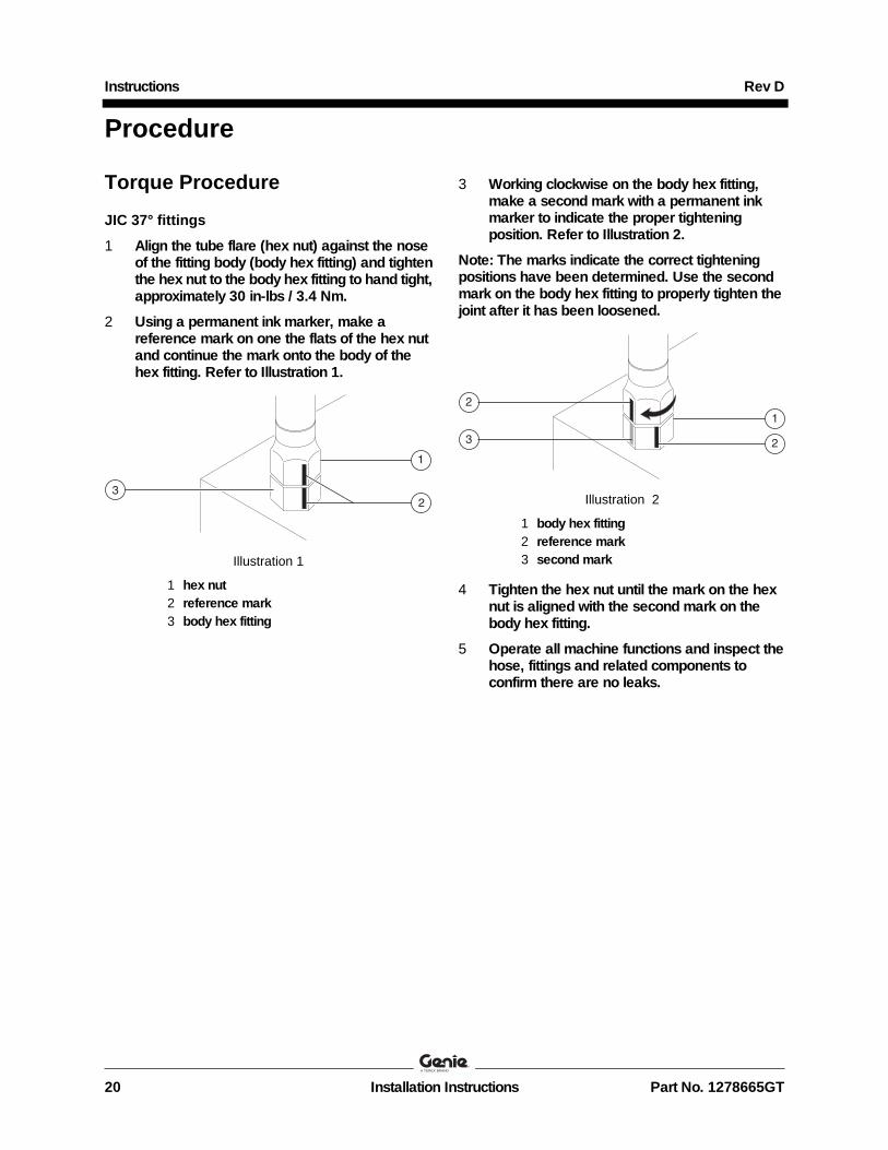
3 Working clockwise on the body hex fitting, make a second mark with a permanent ink marker to indicate the proper tightening position. Refer to Illustration 2.
Note: The marks indicate the correct tightening positions have been determined. Use the second mark on the body hex fitting to properly tighten the joint after it has been loosened.
Illustration 2
1 body hex fitting
2 reference mark
3 second mark
4 Tighten the hex nut until the mark on the hex nut is aligned with the second mark on the body hex fitting.
5 Operate all machine functions and inspect the hose, fittings and related components to confirm there are no leaks.

Safety Notice 170012
Completion Form Your signature on this form will verify that you have completed Safety Notice 170012 on the machines listed below.
Please note that this is not a Warranty Claim Form. A Warranty Claim Form must be submitted to the Terex AWP Warranty Department for reimbursement under the provisions of our standard warranty terms and conditions.
Fax to:
United States: 1 877-738-7530 France: + 33 237 260 998
Canada: 1 425-498-7530 Germany: + 49 4221 491 820
Australia: + 61 733751002 Italy: + 39 075 941 8146
All other locations: + 1-425-498-7530 Iberica: + 34 935 725 080
Scandinavia: + 46 3157 5104
Middle East: + 97 143 990 382
All other locations: + 31 165 510 826
Email to: [email protected]
Date:
Company Name:
Account # (if applicable):
Address:
(street):
(city):
(state, zip code):
Phone:
Please list the complete machine serial number (ex. SX15015H-139, SX18016H-439).).
Serial Number: Serial Number:
Print (service manager) Signature Date Instructions Part No. 1278665GT
Rev D
Installation Instructions
Wear Pad Replacement