fire fighter telephone - fire-lite alarms · firelite’s ecc-fft is a fire fighter telephone...
TRANSCRIPT
ECC-FFTFire Fighter Telephone
Fire Fighter Telephone
DF-60735:B • C-230
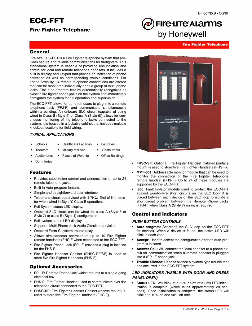
GeneralFirelite’s ECC-FFT is a Fire Fighter telephone system that pro-vides secure and reliable communications for firefighters. Thisstandalone system is capable of providing annunciation andcontrol for local and remote telephone handsets. It includes abuilt in display and keypad that provide an indication of phoneactivation as well as corresponding trouble conditions. Foradded flexibility, 24 remote telephone connections are offeredthat can be monitored individually or as a group of multi-phonejacks. The auto-program feature automatically recognizes allexisting fire fighter phone jacks on the system and immediatelyconfigures the system for full operation and supervision.
The ECC-FFT allows for up to ten users to plug in to a remotetelephone jack (FPJ-F) and communicate simultaneouslywithin a building. An onboard SLC circuit (capable of beingwired in Class B (Style 4) or Class A (Style 6)) allows for con-tinuous monitoring of the telephone jacks connected to thesystem. It is housed in a lockable cabinet that includes multipleknockout locations for field wiring.
TYPICAL APPLICATIONS
Features• Provides supervision control and annunciation of up to 24
remote telephone jacks.• Built-in Auto-program feature.• Simple and straightforward user interface.
• Telephone circuit supervised with 4.7KΩ, End of line resis-tor when wired in Style Y, Class B operation.
• Full System status LED display.• Onboard SLC circuit can be wired for class A (Style 6 or
Style 7) or class B (Style 4) configuration. • Full system status LED display.• Supports Multi-Phone Jack Audio Circuit supervision.
• Onboard Form-C system trouble relay.• Allows simultaneous operation of up to 10 Fire Fighter
remote handsets (FHS-F when connected to the ECC-FFT.• Fire Fighter Phone Jack (FPJ-F provides a plug-in location
for the FHS-F.• Fire Fighter Handset Cabinet (FHSC-RF/SF) is used to
store five Fire Fighter Handsets (FHS-F).
Optional Accessories• FPJ-F: Remote Phone Jack which mounts to a single-gang
electrical box.• FHS-F: Fire Fighter Handset used to communicate over the
telephone circuit connected to the ECC-FFT.• FHSC-RF: Fire Fighter Handset Cabinet (recess mount) is.
used to store five Fire Fighter Handsets (FHS-F).
• FHSC-SF: Optional Fire Fighter Handset Cabinet (surfacemount) is used to store five Fire Fighter Handsets (FHS-F).
• MMF-301: Addressable monitor module that can be used tomonitor the connection of the Fire Fighter Telephoneremote handset (FHS-F). Up to 24 of these modules aresupported by the ECC-FFT.
• I300: Fault Isolator module used to protect the ECC-FFTagainst wire-to-wire short circuits on the SLC loop. It isplaced between each device or the SLC loop to isolate ashort-circuit problem between the Remote Phone Jacks(FPJ-F) when Class A (Style 7) wiring is required
Control and indicators
PUSH BUTTON CONTROLS• Auto-program: Searches the SLC loop on the ECC-FFT
for devices. When a device is found, the active LED willblink in each zone.
• Accept: Used to accept the configuration after an auto-pro-gram is initiated.
• Answer Call: Will connect the local handset to a phone cir-cuit for communication when a remote handset is pluggedinto a (FPJ-F phone jack.
• Trouble Silence: Used to silence a system type trouble thathas occurred in the ECC-FFT system.
LED INDICATORS (VISIBLE WITH DOOR AND DRESSPANEL OPEN) • Status LED: Will blink at a 50% on/off rate until FFT initial-
ization is complete (which takes approximately 20 sec-onds). Once initialization is complete, the status LED willblink at a 10% on and 90% off rate.
• Schools • Healthcare Facilities • Factories
• Theaters • Military facilities • Restaurants
• Auditoriums • Places of Worship • Office Buildings
• Dormitories
DF-60735:B • 8/26/14 — Page 1 of 4
• Answer Call: When a remote handset is connected to theaudio channel, this LED will blink and the piezo will sound.The operator at the FFT then picks up the local handset andpresses the Answer button which causes the Answer CallLED to remain on steady and the piezo goes silent. Oncethe last remote handset has been disconnected from theFFT, the answer LED will go blank and the system will beback to normal.
• Power: Indicates that 24 VDC is connected to the FFT.
• Local Trouble: Will activate and blink when there is a prob-lem with the local handset.
• Remote Trouble: Will activate and blink when there is aproblem with the phone circuit.
• General Trouble: Will blink active when system troublesare detected. When the Trouble Silence button is pressed,the General Trouble LED will light steady. Once all systemtroubles have been restored, the General Trouble LED willturn off.
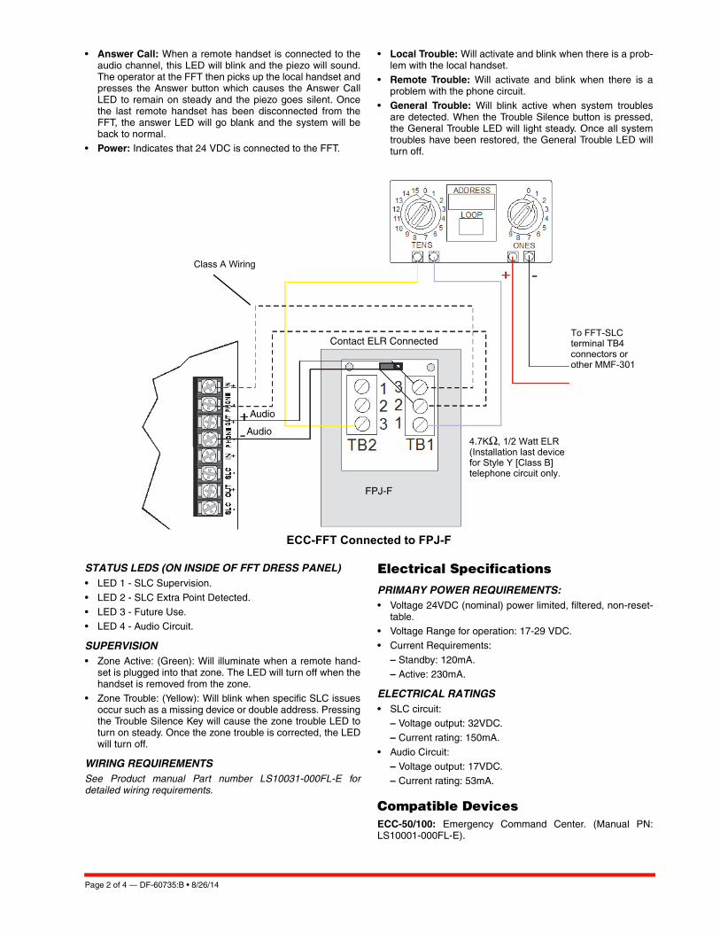
ECC-FFT Connected to FPJ-F
STATUS LEDS (ON INSIDE OF FFT DRESS PANEL)• LED 1 - SLC Supervision.
• LED 2 - SLC Extra Point Detected.• LED 3 - Future Use.• LED 4 - Audio Circuit.
SUPERVISION• Zone Active: (Green): Will illuminate when a remote hand-
set is plugged into that zone. The LED will turn off when thehandset is removed from the zone.
• Zone Trouble: (Yellow): Will blink when specific SLC issuesoccur such as a missing device or double address. Pressingthe Trouble Silence Key will cause the zone trouble LED toturn on steady. Once the zone trouble is corrected, the LEDwill turn off.
WIRING REQUIREMENTSSee Product manual Part number LS10031-000FL-E fordetailed wiring requirements.
Electrical Specifications
PRIMARY POWER REQUIREMENTS:• Voltage 24VDC (nominal) power limited, filtered, non-reset-
table.• Voltage Range for operation: 17-29 VDC.• Current Requirements:
– Standby: 120mA. – Active: 230mA.
ELECTRICAL RATINGS• SLC circuit:
– Voltage output: 32VDC.– Current rating: 150mA.
• Audio Circuit:– Voltage output: 17VDC.– Current rating: 53mA.
Compatible DevicesECC-50/100: Emergency Command Center. (Manual PN:LS10001-000FL-E).
FPJ-F
Class A Wiring
Audio
Audio
Contact ELR Connected
4.7KΩ, 1/2 Watt ELR (Installation last device for Style Y [Class B] telephone circuit only.
To FFT-SLC terminal TB4 connectors or other MMF-301
Page 2 of 4 — DF-60735:B • 8/26/14
MS-9200UDLS: Addressable Fire Alarm Control Panel (Man-ual PN: 52750).
MS-9600(UD)LS: Addressable Fire Alarm Control Panel (Man-ual PN: 52646).
FCPS-24FS6/8: Field Charger/Power Supply.(Manual PN:51883).
Product Line InformationECC-FFT: Fire Fighter Telephone System.
FPJ-F: Remote Phone Jack.
FHS-F: Fire Fighters Remote Handset.
FHSC-RF: Fire Fighters Handset Cabinet Recessed.
FHSC-SF: Fire Fighters Handset Cabinet Surface Mount.
MMF-301: Addressable Mini-Monitor Module.
I300: SLC Line Isolation Module.
TR-CE: Optional Trim Ring.
THUMBLTCH: Optional Thumb Latch. (Non UL Listed).
Total System Capacity• Total Remote telephone jacks (FPJ-F) supported: 24.• Total MMF-301 devices supported: 24.
• Total FF Handsets (FHS-F) capable of activation atonce: 10.
Cabinet SpecificationsBackbox: 19.0"(48.26cm) high x 16.65"(42.29 cm) wide x5.2"(13.23) deep.
Door: 19.26”(48.92cm)high x 16.821”(42.73cm) wide x)670”(1.707cm).
Shipping Specifications Weight: 50.6 lbs (22.95kg).
Temperature and Humidity rangesThis system meets NFPA requirements for operation at 0-49ºC/32-120º F and at a relative humidity 93% ± 2% RH (non-condensing) at 32°C ± 2°C (90°F ± 3°F). However, the usefullife of the system's standby batteries and the electronic com-ponents may be adversely affected by extreme temperatureranges and humidity. Therefore, it is recommended that thissystem and its peripherals be installed in an environment witha normal room temperature of 15-27º C/60-80º F.
Agency Listings and ApprovalsThe listings and approvals below apply to the basic ECC-FFTFire Fighter Telephone system. In some cases, certain mod-ules may not be listed by certain approval agencies or listingmay be in process. Consult factory for latest listing status.
• UL Listed: S2424.• FDNY: COA #6152.
• CSFM: 6912-0075:0028
Standards and Codes The ECC-FFT complies with the following UL Standards andwith NFPA 72 Fire Alarm system requirements.
– UL 864.
DF-60735:B • 8/26/14 — Page 3 of 4

©2014 by Honeywell International Inc. All rights reserved. Unauthorized useof this document is strictly prohibited.
Page 4 of 4 — DF-60735:B • 8/26/14
This document is not intended to be used for installation purposes. We try to keep our product information up-to-date and accurate.
We cannot cover all specific applications or anticipate all requirements. All specifications are subject to change without notice.
For more information, contact Fire•Lite Alarms. Phone: (800) 627-3473, FAX: (877) 699-4105.www.firelite.com
Made in the U.S. A.