finite element vibration analysis of laminated composite...
TRANSCRIPT
273
Finite element vibration analysis of laminatedcomposite folded plate structures
A. Guha Niyogi, M.K. Laha and P.K. Sinha∗
Department of Aerospace Engineering, IndianInstitute of Technology, Kharagpur – 721 302, India
Received 4 April 1999
Revised 22 October 1999
A nine-noded Lagrangian plate bending finite element thatincorporates first-order transverse shear deformation and ro-tary inertia is used to predict the free and forced vibra-tion response of laminated composite folded plate structures.A 6 × 6 transformation matrix is derived to transform thesystem element matrices before assembly. The usual fivedegrees-of-freedom per node is appended with an additionaldrilling degree of freedom in order to fit the transformation.The present finite element results show good agreement withthe available semi-analytical solutions and finite element re-sults. Parametric studies are conducted for free and forced vi-bration analysis for laminated folded plates, with referenceto crank angle, fibre angle and stacking sequence. The nat-ural frequencies and mode shapes, and forced vibration re-sponses furnished here may serve as a benchmark for futureinvestigations.
Keywords: Composite, finite element method, stacking se-quence, transverse shear, folded plates, crank angle, transfor-mation
1. Introduction
Folded plate structures have a wide range of engi-neering applications in aircraft fuselages, ship hulls,buildings, bridges and vehicle chassis, among otherstructures. With the advent of fiber-reinforced lam-inated composites, the applicability of folded platestructures has increased many folds due to their lowweight, high stiffness and high strength properties.Structural properties of the laminated composites canbe tailored to realize better performance by controllingthe lamination angle and stacking sequence. Literature
* Corresponding author. Tel.: +91 3222 77997; Fax: +91 322255303/55239; E-mail: [email protected]
in the field of dynamic analysis of laminated compositefolded plates is scanty and the present paper is meantto address the dynamic behaviour of composite foldedplate structures, in view of its tremendous potentials.
Historically, Goldberg and Leve [8] pioneered theexact static analysis of folded plate structures. Irie etal. [10] calculated the natural frequencies of cantileverfolded plates by Ritz method. Ohga and Shinematsu[17] applied boundary element-transfer matrix methodto solve the bending problem of folded plates. Golleyand Grice [9] and Eterovic and Godoy [7] employedfinite strip methods. Danial [4] and Danial et al. [5] in-troduced a concept entitled Spectral Element Method.Liu and Huang [12] had used a finite element-transfermatrix method to analyze one- and two-fold foldedplates. Bathe [1] and Zienkeiwicz and Taylor [21] hadpresented a method of flat shell analysis, which can bedirectly applied to folded plate structures. However, allthese works relate to isotropic folded plate structuresonly.
For the finite element analysis of laminated compos-ite plates with first and higher order shear deformationtheories (FST, HST) several works may be referred to.The works of Reddy [18], Kant et al. [11], Meimarisand Day [16], Bert and Chen [2], Chatterjee and Kulka-rni [3], Dong and Chun [6] and Maiti and Sinha [13–15] may be cited to name only a few. Recently, Sureshand Malhotra [19] conducted damped free vibrationanalysis of composite box beams using 4 noded platefinite element with five degrees of freedom (u,v,w, θxandθy) per node.
In the present analysis the FST is adopted to analyzethe laminated composite folded plates. A shear cor-rection factor of 5/6 has been assumed, which is de-rived from the Timoshenko beam concept by applyingthe energy principle. A comparative study using FSTand HST [13–15] clearly indicates that the present firstorder shear deformation theory provides excellent re-sults for moderately thick composite beams, plates andshells for all practical situations. Attention is thereforerestricted to application of FST for the development
Shock and Vibration 6 (1999) 273–283ISSN 1070-9622 / $8.00 1999, IOS Press. All rights reserved
274 A. Guha Niyogi et al. / Finite element vibration analysis of laminated composite folded plate structures
of the finite element analysis procedure for compositefolded plates.
The transformations used to generate the globalmass, stiffness and load arrays are presented. The re-sults of free vibration analysis and also transient anal-ysis of cantilever laminated folded plates, subjected tosuddenly applied step loading are presented. The tran-sient analysis is done using the Newmark’s direct in-tegration scheme [1]. Parametric studies are conductedby varying the crank angle, fibre orientation and num-ber of layers for the laminated composite folded plate.The present methodology can easily be applied to theanalysis of box beams and closed structures.
2. Theoretical formulation
In the classical thin plate theory, it is assumed thatnormals to the mid-plane before deformation remainnormal and plane after deformation. This assump-tion neglects the effect of transverse shear deforma-tion. Here Mindlin’s assumptions, as given below, areadopted to incorporate the first order transverse sheareffects:
i) The deflection of the mid-plane of the plate issmall compared to the plate thickness.
ii) The transverse normal stress is neglected.iii) Normals to the mid-plane of the plates before
deformation remain straight but not necessarilynormal after deformation.
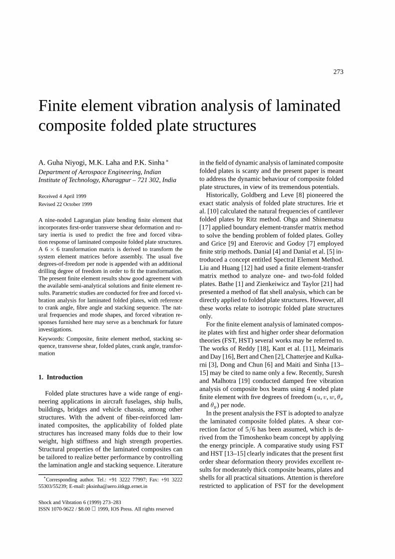
The displacements of the plate are fully describedby five components:u,v,w, θx, θy, whereu,v andware displacements along thex,y andz-directions andθx andθy are rotations abouty- andx-axes. The pos-itive sign conventions for displacements and stress re-sultants are illustrated in Fig. 1.
Fig. 1. The laminated composite plate with positive displacements,rotations and stress resultants.
2.1. Flat plate finite element formulation forcomposite plates
The displacements at a nodej of a plate element areuj, vj ,wj , θxj andθyj . The displacements at any pointwithin the element can be expressed as
uvwθxθy
=9∑j=1
Nj [I5]
ujvjwjθxjθyj
, (1)
where [I5] is a 5 × 5 identity matrix andNj areLagrangian interpolation functions [1]. For Mindlinplates the following relationship is valid:{
uvw
}=
{u0 + zθxv0 + zθyw0
}and
{θxθy
}=
∂w
∂x+ φx
∂w
∂y+ φy
, (2)
whereθx andθy are the total rotations,φx andφy arethe average shear deformations about they andx axes,andu0,v0 andw0 are the mid-plane translations alongx,y andz directions.
2.2. Stiffness matrix of plate element
The stiffness matrix of the plate element assumes theform
[K]e =
∫Ae
[B]T[D][B] dA, (3)
where
{ ε} = [B]{ δ} . (4)
Here, {ε} is the strain vector and {δ} is the nodal dis-placement vector. The strain–displacement matrix [B]is given in
[B]{ δ}
=9∑j=1
Nj,x 0 0 0 00 Nj,y 0 0 0
Nj,y Nj,x 0 0 00 0 0 Nj,x 00 0 0 0 Nj,y
0 0 0 Nj,y Nj,x
0 0 Nj,y 0 Nj0 0 Nj,x Nj 0
u0j
v0j
w0j
θxjθyj
.(5)
A. Guha Niyogi et al. / Finite element vibration analysis of laminated composite folded plate structures 275
[D] is the stiffness matrix given by
[D] =
A11 A12 A16 B11 B12 B16 0 0A12 A22 A26 B12 B22 B26 0 0A16 A26 A66 B16 B26 B66 0 0B11 B12 B16 D11 D12 D16 0 0B12 B22 B26 D12 D22 D26 0 0B16 B26 B66 D16 D26 D66 0 00 0 0 0 0 0 A44 A45
0 0 0 0 0 0 A45 A55
(6)
where
Aij ,Bij ,Dij =N∑k=1
∫ zk
zk−1
(Qij)k
(1,z, z2) dz,
i, j = 1, 2, 6 (7a)
and
Aij =N∑k=1
∫ zk
zk−1
κ(Qij)k dz,
i, j = 4, 5, κ = 5/6. (7b)
Here,Qij are the elements of off-axis stress–strain re-lations.Qkij relates stresses and strains in thekth layerby the relationσki = Qkijε
kj , i, j = 1, 2, 6, whereas
σkl = Qklmεkm, l,m = 4, 5 andκ is the shear correction
factor.Qkij for thekth layer is expressed as
{σ1
σ2
σ6
}k=
[Q11 Q12 Q16
Q12 Q22 Q26
Q16 Q26 Q66
]k{ ε1
ε2
ε6
}kand
{σ4
σ5
}k=
[Q44 Q45
Q45 Q55
]k {ε4
ε5
}k. (8)
Here,σ1,σ2,σ4,σ5, andσ6 denoteσx,σy, τyz, τzx andτxy, respectively, andε1, ε2, ε4, ε5, andε6 stands forεx, εy,γyz,γzx andγxy, respectively.
2.3. Mass matrix of plate element
In matrix form the equation of motions for theMindlin plate may be written as follows:
Nx,x +Nxy,y
Nxy,x +Ny,y
Qx,x +Qy,y + qMx,x +Mxy,y
Mxy,x +My,y
=
I 0 0 P 00 I 0 0 P0 0 I 0 0P 0 0 Q 00 P 0 0 Q
u0
v0
w0
θxθy
,
(I,P ,Q) =
∫ h/2
−h/2ρ(1,z, z2)dz
or
{F } = [ρ]{A}, (9)
where {F } is the force vector, [ρ] is the inertia matrix,and {A} is the acceleration vector. The mass matrix ofthe plate element is given by
[M ]e =
∫Ae
[N ]T[ρ][N ] dA, (10)
where [N ] are the Lagrangian interpolation functions.
2.4. Load vector
The element load vector for forced vibration analy-sis is given by∫
Ae
[N ]Tq dA, (11)
whereq is the transverse load intensity on the element.The integration in every case is carried out over thearea of the plate element. Generally, a 3-point Gaussquadrature is adopted to compute the bending stiff-ness of the elements, whereas a 2-point integrationis adopted to calculate the shear stiffness, mass ma-trix, and element force vector. A 2-point eliminates theshear locking in thin plates. It is also known that a 2-point integration for both the mass matrix and forcevector is adequate.
2.5. Transformations for folded plate
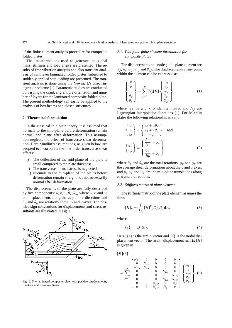
With reference to Fig. 2, the relations between localand global displacements are given as
Fig. 2. Local (unprimed) and global (primed) axes system for a typi-cal folded plate element. The least angle contained between positivex′ andx axes is denoted as (x′,x).
276 A. Guha Niyogi et al. / Finite element vibration analysis of laminated composite folded plate structuresuvwθxθyθz
=
cos(x′,x) cos(y′,x) cos(z′,x)cos(x′,y) cos(y′,y) cos(z′,y)cos(x′, z) cos(y′, z) cos(z′,z)
0 0 00 0 00 0 0
0 0 00 0 00 0 0
cos(y′,y) − cos(x′,y) cos(z′,y)− cos(y′,x) cos(x′,x) − cos(z′,x)cos(y′,z) − cos(x′,z) cos(z′, z)
u′
v′
w′
θ′xθ′yθ′z
or
{u} = [T ]{ u′} . (12)
Finally, the global stiffness, mass matrices and forcevector are expressed as
[K ′]e = [T ]T[K]e[T ], (13)
[M ′]e = [T ]T[M ]e[T ], (14)
{f ′} e = [T ]T{f } e. (15)
However, before applying the transformation, the 45×45 stiffness and mass matrices is blown up to 54× 54size, to accommodate the nineθz drilling degrees offreedom per element. The off-diagonal terms corre-sponding to theθz terms are set to zero, while a verysmall positive number is introduced at the correspond-ing leading diagonal terms. This small number is takento be 1000 times smaller than the smallest leading diag-onal term of the corresponding element matrix beforeblowing up [1]. The load vector is similarly enlargedby incorporating null terms in theθz positions.
The free vibration analysis involves the solution of
[M ′]{ x′} + [K ′]{ x′} = {0} (16)
and, the method of subspace iteration [1] is adopted toextract the eigenpairs. In the forced vibration analysis,the damping is neglected, and the force term replacesthe null vector in the right hand side of Eq. (16). New-mark’s explicit integration technique [1] is adopted forthe transient analysis.
3. Numerical results and discussion
The finite element formulation described in the ear-lier section has been used to compare the present re-sults with the published ones and also to generate nu-
merical results to study the effects of crank angle,fibre angle and number of plies used, on the non-dimensional frequencies and responses of compositefolded plates. The definitions for non-dimensionalisedfrequencies are given along with Tables 1 and 2.
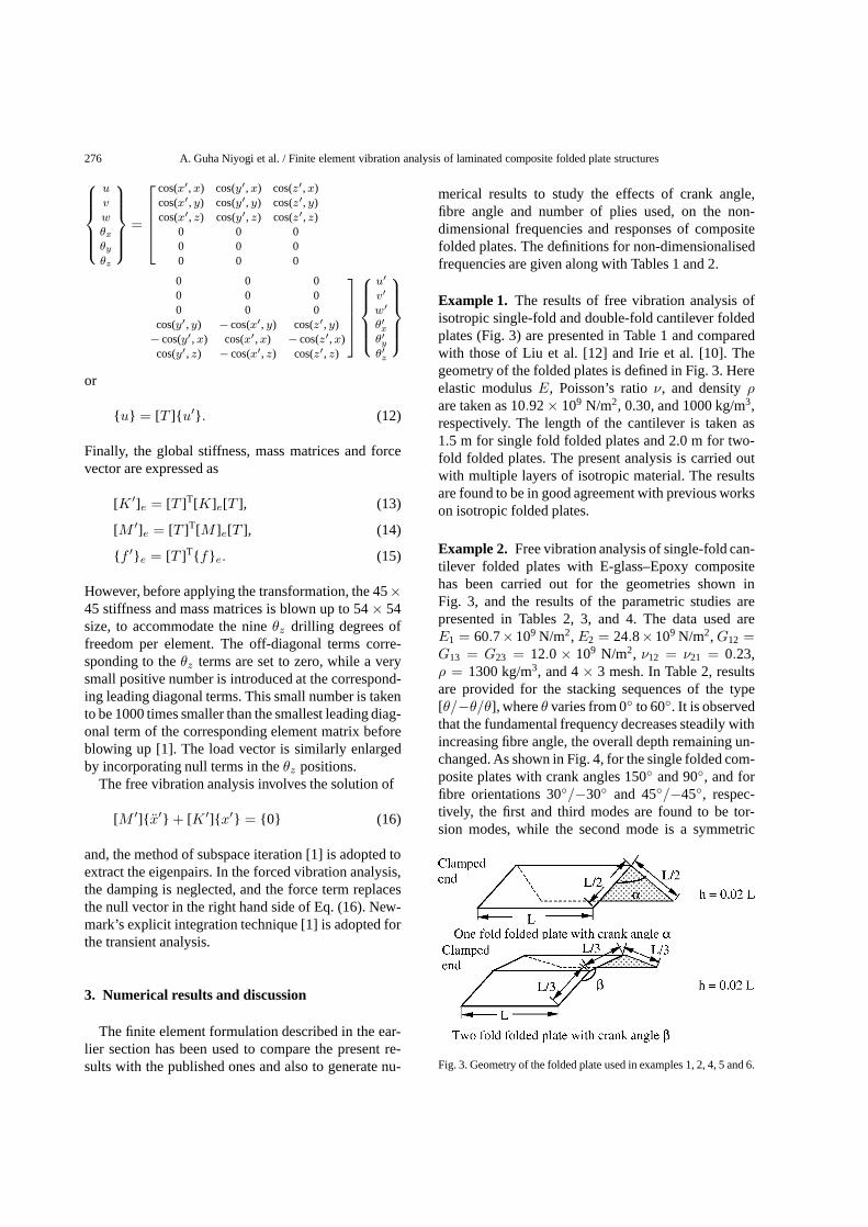
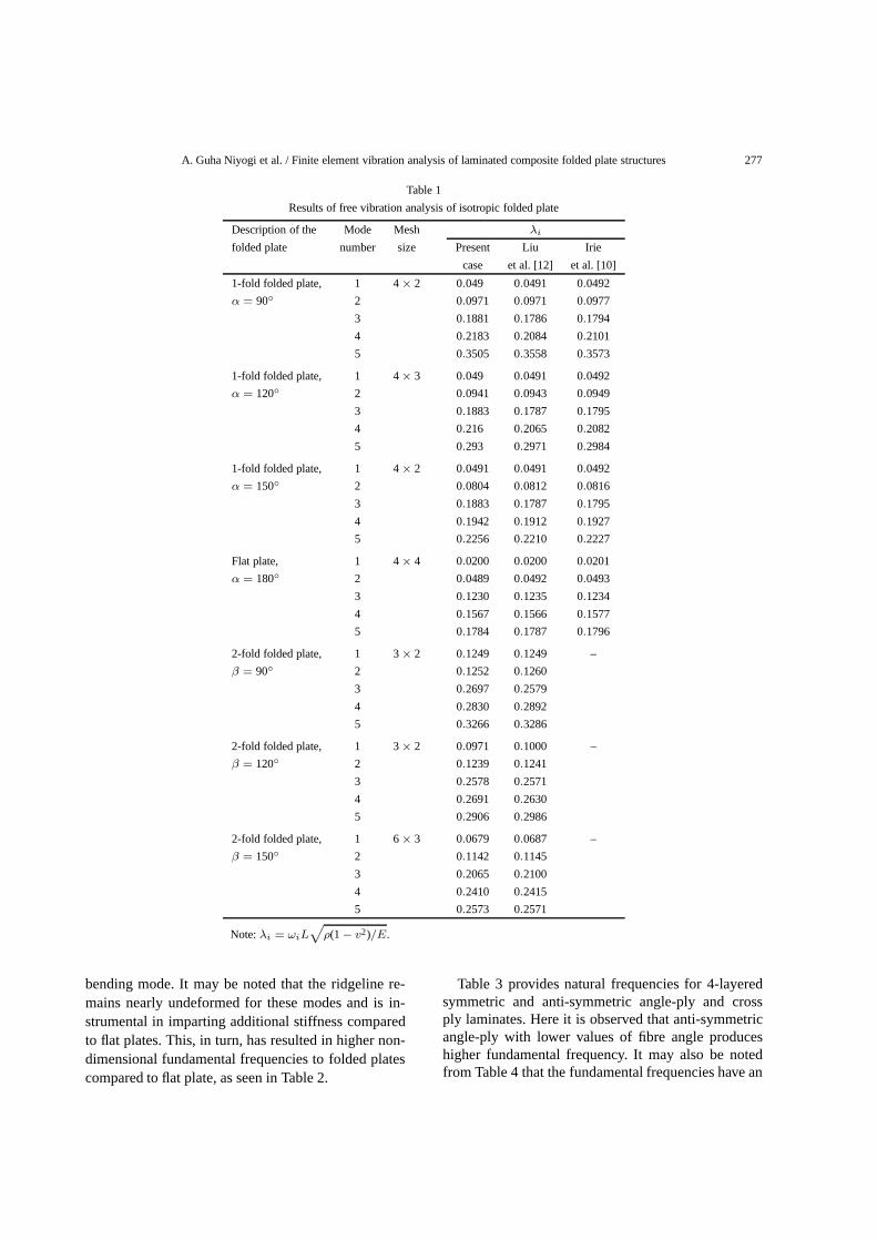
Example 1. The results of free vibration analysis ofisotropic single-fold and double-fold cantilever foldedplates (Fig. 3) are presented in Table 1 and comparedwith those of Liu et al. [12] and Irie et al. [10]. Thegeometry of the folded plates is defined in Fig. 3. Hereelastic modulusE, Poisson’s ratioν, and densityρare taken as 10.92× 10⁹ N/m2, 0.30, and 1000 kg/m3,respectively. The length of the cantilever is taken as1.5 m for single fold folded plates and 2.0 m for two-fold folded plates. The present analysis is carried outwith multiple layers of isotropic material. The resultsare found to be in good agreement with previous workson isotropic folded plates.
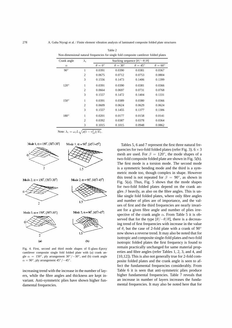
Example 2. Free vibration analysis of single-fold can-tilever folded plates with E-glass–Epoxy compositehas been carried out for the geometries shown inFig. 3, and the results of the parametric studies arepresented in Tables 2, 3, and 4. The data used areE1 = 60.7×10⁹ N/m2,E2 = 24.8×10⁹ N/m2,G12 =G13 = G23 = 12.0× 10⁹ N/m2, ν12 = ν21 = 0.23,ρ = 1300 kg/m3, and 4× 3 mesh. In Table 2, resultsare provided for the stacking sequences of the type[θ/−θ/θ], whereθ varies from 0◦ to 60◦. It is observedthat the fundamental frequency decreases steadily withincreasing fibre angle, the overall depth remaining un-changed. As shown in Fig. 4, for the single folded com-posite plates with crank angles 150◦ and 90◦, and forfibre orientations 30◦/−30◦ and 45◦/−45◦, respec-tively, the first and third modes are found to be tor-sion modes, while the second mode is a symmetric
Fig. 3. Geometry of the folded plate used in examples 1, 2, 4, 5 and 6.
A. Guha Niyogi et al. / Finite element vibration analysis of laminated composite folded plate structures 277
Table 1
Results of free vibration analysis of isotropic folded plate
Description of the Mode Mesh λi
folded plate number size Present Liu Irie
case et al. [12] et al. [10]
1-fold folded plate, 1 4× 2 0.049 0.0491 0.0492
α = 90◦ 2 0.0971 0.0971 0.0977
3 0.1881 0.1786 0.1794
4 0.2183 0.2084 0.2101
5 0.3505 0.3558 0.3573
1-fold folded plate, 1 4× 3 0.049 0.0491 0.0492
α = 120◦ 2 0.0941 0.0943 0.0949
3 0.1883 0.1787 0.1795
4 0.216 0.2065 0.2082
5 0.293 0.2971 0.2984
1-fold folded plate, 1 4× 2 0.0491 0.0491 0.0492
α = 150◦ 2 0.0804 0.0812 0.0816
3 0.1883 0.1787 0.1795
4 0.1942 0.1912 0.1927
5 0.2256 0.2210 0.2227
Flat plate, 1 4× 4 0.0200 0.0200 0.0201
α = 180◦ 2 0.0489 0.0492 0.0493
3 0.1230 0.1235 0.1234
4 0.1567 0.1566 0.1577
5 0.1784 0.1787 0.1796
2-fold folded plate, 1 3× 2 0.1249 0.1249 –
β = 90◦ 2 0.1252 0.1260
3 0.2697 0.2579
4 0.2830 0.2892
5 0.3266 0.3286
2-fold folded plate, 1 3× 2 0.0971 0.1000 –
β = 120◦ 2 0.1239 0.1241
3 0.2578 0.2571
4 0.2691 0.2630
5 0.2906 0.2986
2-fold folded plate, 1 6× 3 0.0679 0.0687 –
β = 150◦ 2 0.1142 0.1145
3 0.2065 0.2100
4 0.2410 0.2415
5 0.2573 0.2571
Note:λi = ωiL√ρ(1− v2)/E.
bending mode. It may be noted that the ridgeline re-mains nearly undeformed for these modes and is in-strumental in imparting additional stiffness comparedto flat plates. This, in turn, has resulted in higher non-dimensional fundamental frequencies to folded platescompared to flat plate, as seen in Table 2.
Table 3 provides natural frequencies for 4-layeredsymmetric and anti-symmetric angle-ply and crossply laminates. Here it is observed that anti-symmetricangle-ply with lower values of fibre angle produceshigher fundamental frequency. It may also be notedfrom Table 4 that the fundamental frequencies have an
278 A. Guha Niyogi et al. / Finite element vibration analysis of laminated composite folded plate structures
Table 2
Non-dimensional natural frequencies for single fold composite cantilever folded plates
Crank angle λi Stacking sequence [θ/−θ/θ]
α θ = 0◦ θ = 30◦ θ = 45◦ θ = 60◦
90◦ 1 0.0391 0.0390 0.0381 0.0367
2 0.0675 0.0712 0.0753 0.0804
3 0.1556 0.1473 0.1406 0.1399
120◦ 1 0.0391 0.0390 0.0381 0.0366
2 0.0664 0.0697 0.0731 0.0768
3 0.1557 0.1472 0.1404 0.1331
150◦ 1 0.0391 0.0389 0.0380 0.0366
2 0.0609 0.0624 0.0629 0.0624
3 0.1557 0.1455 0.1377 0.1306
180◦ 1 0.0201 0.0177 0.0158 0.0141
2 0.0392 0.0387 0.0378 0.0364
3 0.1015 0.1015 0.0948 0.0862
Note:λi = ωiL√ρ(1− v2
12)/E1.
Fig. 4. First, second and third mode shapes of E-glass–Epoxycantilever composite single fold folded plate with (a) crank an-gle α = 150◦, ply arrangement 30◦/−30◦, and (b) crank angleα = 90◦, ply arrangement 45◦/−45◦.
increasing trend with the increase in the number of lay-ers, while the fibre angles and thickness are kept in-variant. Anti-symmetric plies have shown higher fun-damental frequencies.
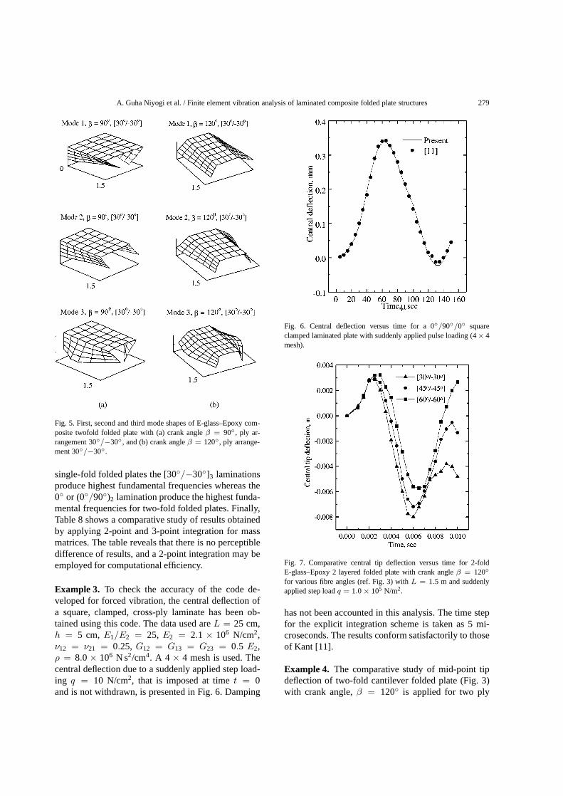
Tables 5, 6 and 7 represent the first three natural fre-quencies for two-fold folded plates (refer Fig. 3). 6×3mesh are used. Forβ = 120◦, the mode shapes of atwo-fold composite folded plate are shown in Fig. 5(b).The first mode is a torsion mode. The second modeis a symmetric bending mode and the third is a sym-metric mode too, though complex in shape. Howeverthis trend is not repeated forβ = 90◦, as shown inFig. 5(a). Thus, Fig. 5 shows that the mode shapesfor two-fold folded plates depend on the crank an-glesβ heavily, as also on the fibre angles. This is un-like single fold folded plates, where only fibre anglesand number of plies are of importance, and the val-ues of first and the third frequencies are nearly invari-ant for a given fibre angle and number of plies irre-spective of the crank angleα. From Table 5 it is ob-served that for the type [θ/−θ/θ], there is a decreas-ing trend of first frequencies with increase in the valueof θ, but the case of 2-fold plate with a crank of 90◦
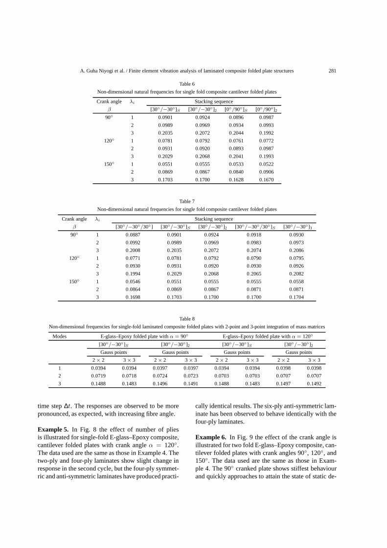
now shows a reverse trend. It may also be noted that forisotropic and composite single-fold plates and two-foldisotropic folded plates the first frequency is found toremain practically unchanged for same material prop-erties and fibre angles (refer Tables 1, 2, 3, and 4, and[10,12]). This is also not generally true for 2-fold com-posite folded plates and the crank angle is seen to af-fect the fundamental frequencies considerably. FromTable 6 it is seen that anti-symmetric plies producehigher fundamental frequencies. Table 7 reveals thatan increase in number of layers increases the funda-mental frequencies. It may also be noted here that for
A. Guha Niyogi et al. / Finite element vibration analysis of laminated composite folded plate structures 279
Fig. 5. First, second and third mode shapes of E-glass–Epoxy com-posite twofold folded plate with (a) crank angleβ = 90◦, ply ar-rangement 30◦/−30◦, and (b) crank angleβ = 120◦, ply arrange-ment 30◦/−30◦.
single-fold folded plates the [30◦/−30◦]3 laminationsproduce highest fundamental frequencies whereas the0◦ or (0◦/90◦)2 lamination produce the highest funda-mental frequencies for two-fold folded plates. Finally,Table 8 shows a comparative study of results obtainedby applying 2-point and 3-point integration for massmatrices. The table reveals that there is no perceptibledifference of results, and a 2-point integration may beemployed for computational efficiency.
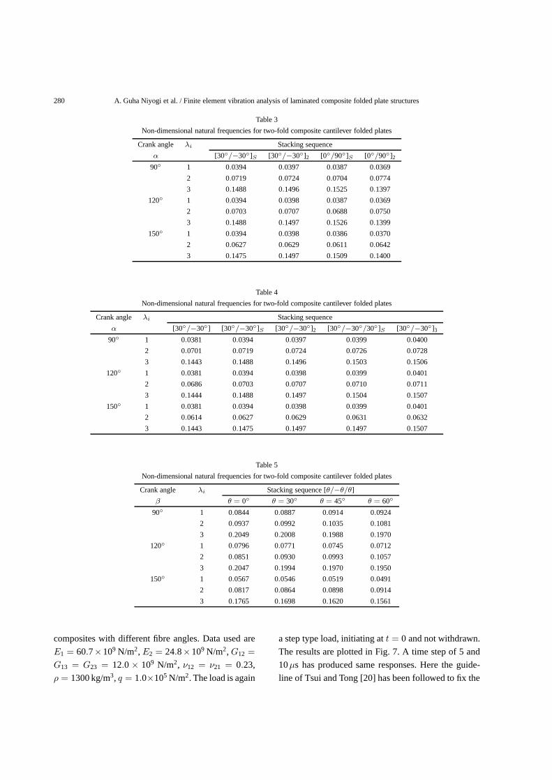
Example 3. To check the accuracy of the code de-veloped for forced vibration, the central deflection ofa square, clamped, cross-ply laminate has been ob-tained using this code. The data used areL = 25 cm,h = 5 cm,E1/E2 = 25, E2 = 2.1 × 10⁶ N/cm2,ν12 = ν21 = 0.25, G12 = G13 = G23 = 0.5 E2,ρ = 8.0× 10⁶ N s2/cm4. A 4 × 4 mesh is used. Thecentral deflection due to a suddenly applied step load-ing q = 10 N/cm2, that is imposed at timet = 0and is not withdrawn, is presented in Fig. 6. Damping
Fig. 6. Central deflection versus time for a 0◦/90◦/0◦ squareclamped laminated plate with suddenly applied pulse loading (4× 4mesh).
Fig. 7. Comparative central tip deflection versus time for 2-foldE-glass–Epoxy 2 layered folded plate with crank angleβ = 120◦
for various fibre angles (ref. Fig. 3) withL = 1.5 m and suddenlyapplied step loadq = 1.0× 10⁵ N/m2.
has not been accounted in this analysis. The time stepfor the explicit integration scheme is taken as 5 mi-croseconds. The results conform satisfactorily to thoseof Kant [11].
Example 4. The comparative study of mid-point tipdeflection of two-fold cantilever folded plate (Fig. 3)with crank angle,β = 120◦ is applied for two ply
280 A. Guha Niyogi et al. / Finite element vibration analysis of laminated composite folded plate structures
Table 3
Non-dimensional natural frequencies for two-fold composite cantilever folded plates
Crank angle λi Stacking sequence
α [30◦/−30◦]S [30◦/−30◦]2 [0◦/90◦]S [0◦/90◦]2
90◦ 1 0.0394 0.0397 0.0387 0.0369
2 0.0719 0.0724 0.0704 0.0774
3 0.1488 0.1496 0.1525 0.1397
120◦ 1 0.0394 0.0398 0.0387 0.0369
2 0.0703 0.0707 0.0688 0.0750
3 0.1488 0.1497 0.1526 0.1399
150◦ 1 0.0394 0.0398 0.0386 0.0370
2 0.0627 0.0629 0.0611 0.0642
3 0.1475 0.1497 0.1509 0.1400
Table 4
Non-dimensional natural frequencies for two-fold composite cantilever folded plates
Crank angle λi Stacking sequence
α [30◦/−30◦] [30◦/−30◦]S [30◦/−30◦]2 [30◦/−30◦/30◦]S [30◦/−30◦]3
90◦ 1 0.0381 0.0394 0.0397 0.0399 0.0400
2 0.0701 0.0719 0.0724 0.0726 0.0728
3 0.1443 0.1488 0.1496 0.1503 0.1506
120◦ 1 0.0381 0.0394 0.0398 0.0399 0.0401
2 0.0686 0.0703 0.0707 0.0710 0.0711
3 0.1444 0.1488 0.1497 0.1504 0.1507
150◦ 1 0.0381 0.0394 0.0398 0.0399 0.0401
2 0.0614 0.0627 0.0629 0.0631 0.0632
3 0.1443 0.1475 0.1497 0.1497 0.1507
Table 5
Non-dimensional natural frequencies for two-fold composite cantilever folded plates
Crank angle λi Stacking sequence [θ/−θ/θ]
β θ = 0◦ θ = 30◦ θ = 45◦ θ = 60◦
90◦ 1 0.0844 0.0887 0.0914 0.0924
2 0.0937 0.0992 0.1035 0.1081
3 0.2049 0.2008 0.1988 0.1970
120◦ 1 0.0796 0.0771 0.0745 0.0712
2 0.0851 0.0930 0.0993 0.1057
3 0.2047 0.1994 0.1970 0.1950
150◦ 1 0.0567 0.0546 0.0519 0.0491
2 0.0817 0.0864 0.0898 0.0914
3 0.1765 0.1698 0.1620 0.1561
composites with different fibre angles. Data used are
E1 = 60.7×10⁹ N/m2,E2 = 24.8×10⁹ N/m2,G12 =
G13 = G23 = 12.0× 10⁹ N/m2, ν12 = ν21 = 0.23,
ρ = 1300 kg/m3, q = 1.0×10⁵ N/m2. The load is again
a step type load, initiating att = 0 and not withdrawn.
The results are plotted in Fig. 7. A time step of 5 and
10µs has produced same responses. Here the guide-
line of Tsui and Tong [20] has been followed to fix the
A. Guha Niyogi et al. / Finite element vibration analysis of laminated composite folded plate structures 281
Table 6
Non-dimensional natural frequencies for single fold composite cantilever folded plates
Crank angle λi Stacking sequence
β [30◦/−30◦]S [30◦/−30◦]2 [0◦/90◦]S [0◦/90o]2
90◦ 1 0.0901 0.0924 0.0896 0.0987
2 0.0989 0.0969 0.0934 0.0993
3 0.2035 0.2072 0.2044 0.1992
120◦ 1 0.0781 0.0792 0.0761 0.0772
2 0.0931 0.0920 0.0893 0.0987
3 0.2029 0.2068 0.2041 0.1993
150◦ 1 0.0551 0.0555 0.0533 0.0522
2 0.0869 0.0867 0.0840 0.0906
3 0.1703 0.1700 0.1628 0.1670
Table 7
Non-dimensional natural frequencies for single fold composite cantilever folded plates
Crank angle λi Stacking sequence
β [30◦/−30◦/30◦] [30◦/−30◦]S [30◦/−30◦]2 [30◦/−30◦/30◦]S [30◦/−30◦]3
90◦ 1 0.0887 0.0901 0.0924 0.0918 0.0930
2 0.0992 0.0989 0.0969 0.0983 0.0973
3 0.2008 0.2035 0.2072 0.2074 0.2086
120◦ 1 0.0771 0.0781 0.0792 0.0790 0.0795
2 0.0930 0.0931 0.0920 0.0930 0.0926
3 0.1994 0.2029 0.2068 0.2065 0.2082
150◦ 1 0.0546 0.0551 0.0555 0.0555 0.0558
2 0.0864 0.0869 0.0867 0.0871 0.0871
3 0.1698 0.1703 0.1700 0.1700 0.1704
Table 8
Non-dimensional frequencies for single-fold laminated composite folded plates with 2-point and 3-point integration of mass matrices
Modes E-glass–Epoxy folded plate withα = 90◦ E-glass–Epoxy folded plate withα = 120◦
[30◦/−30◦]S [30◦/−30◦]2 [30◦/−30◦]S [30◦/−30◦]2
Gauss points Gauss points Gauss points Gauss points
2× 2 3× 3 2× 2 3× 3 2× 2 3× 3 2× 2 3× 3
1 0.0394 0.0394 0.0397 0.0397 0.0394 0.0394 0.0398 0.0398
2 0.0719 0.0718 0.0724 0.0723 0.0703 0.0703 0.0707 0.0707
3 0.1488 0.1483 0.1496 0.1491 0.1488 0.1483 0.1497 0.1492
time step∆t. The responses are observed to be morepronounced, as expected, with increasing fibre angle.
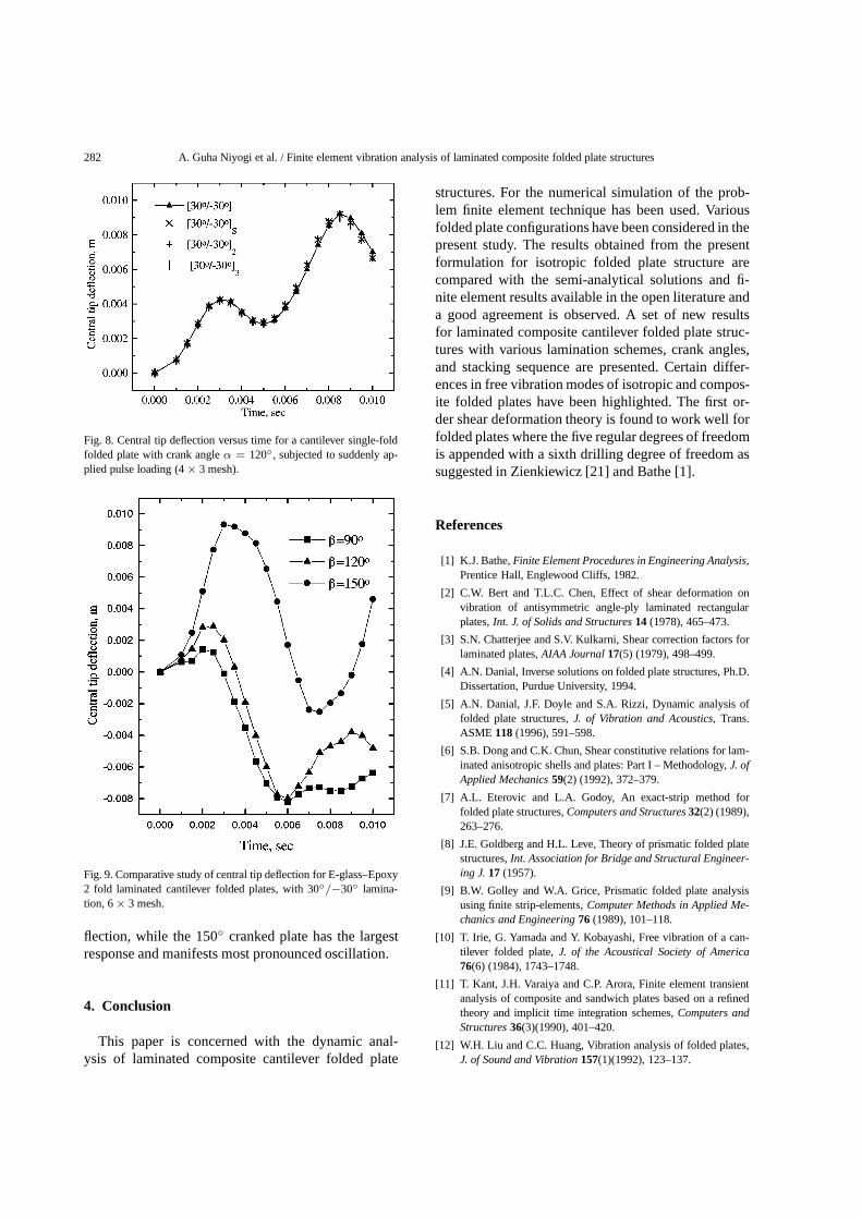
Example 5. In Fig. 8 the effect of number of pliesis illustrated for single-fold E-glass–Epoxy composite,cantilever folded plates with crank angleα = 120◦.The data used are the same as those in Example 4. Thetwo-ply and four-ply laminates show slight change inresponse in the second cycle, but the four-ply symmet-ric and anti-symmetric laminates have produced practi-
cally identical results. The six-ply anti-symmetric lam-inate has been observed to behave identically with thefour-ply laminates.
Example 6. In Fig. 9 the effect of the crank angle isillustrated for two fold E-glass–Epoxy composite, can-tilever folded plates with crank angles 90◦, 120◦, and150◦. The data used are the same as those in Exam-ple 4. The 90◦ cranked plate shows stiffest behaviourand quickly approaches to attain the state of static de-
282 A. Guha Niyogi et al. / Finite element vibration analysis of laminated composite folded plate structures
Fig. 8. Central tip deflection versus time for a cantilever single-foldfolded plate with crank angleα = 120◦, subjected to suddenly ap-plied pulse loading (4× 3 mesh).
Fig. 9. Comparative study of central tip deflection for E-glass–Epoxy2 fold laminated cantilever folded plates, with 30◦/−30◦ lamina-tion, 6× 3 mesh.
flection, while the 150◦ cranked plate has the largestresponse and manifests most pronounced oscillation.
4. Conclusion
This paper is concerned with the dynamic anal-ysis of laminated composite cantilever folded plate
structures. For the numerical simulation of the prob-lem finite element technique has been used. Variousfolded plate configurations have been considered in thepresent study. The results obtained from the presentformulation for isotropic folded plate structure arecompared with the semi-analytical solutions and fi-nite element results available in the open literature anda good agreement is observed. A set of new resultsfor laminated composite cantilever folded plate struc-tures with various lamination schemes, crank angles,and stacking sequence are presented. Certain differ-ences in free vibration modes of isotropic and compos-ite folded plates have been highlighted. The first or-der shear deformation theory is found to work well forfolded plates where the five regular degrees of freedomis appended with a sixth drilling degree of freedom assuggested in Zienkiewicz [21] and Bathe [1].
References
[1] K.J. Bathe,Finite Element Procedures in Engineering Analysis,Prentice Hall, Englewood Cliffs, 1982.
[2] C.W. Bert and T.L.C. Chen, Effect of shear deformation onvibration of antisymmetric angle-ply laminated rectangularplates,Int. J. of Solids and Structures14 (1978), 465–473.
[3] S.N. Chatterjee and S.V. Kulkarni, Shear correction factors forlaminated plates,AIAA Journal17(5) (1979), 498–499.
[4] A.N. Danial, Inverse solutions on folded plate structures, Ph.D.Dissertation, Purdue University, 1994.
[5] A.N. Danial, J.F. Doyle and S.A. Rizzi, Dynamic analysis offolded plate structures,J. of Vibration and Acoustics, Trans.ASME 118(1996), 591–598.
[6] S.B. Dong and C.K. Chun, Shear constitutive relations for lam-inated anisotropic shells and plates: Part I – Methodology,J. ofApplied Mechanics59(2) (1992), 372–379.
[7] A.L. Eterovic and L.A. Godoy, An exact-strip method forfolded plate structures,Computers and Structures32(2) (1989),263–276.
[8] J.E. Goldberg and H.L. Leve, Theory of prismatic folded platestructures,Int. Association for Bridge and Structural Engineer-ing J.17 (1957).
[9] B.W. Golley and W.A. Grice, Prismatic folded plate analysisusing finite strip-elements,Computer Methods in Applied Me-chanics and Engineering76 (1989), 101–118.
[10] T. Irie, G. Yamada and Y. Kobayashi, Free vibration of a can-tilever folded plate,J. of the Acoustical Society of America76(6) (1984), 1743–1748.
[11] T. Kant, J.H. Varaiya and C.P. Arora, Finite element transientanalysis of composite and sandwich plates based on a refinedtheory and implicit time integration schemes,Computers andStructures36(3)(1990), 401–420.
[12] W.H. Liu and C.C. Huang, Vibration analysis of folded plates,J. of Sound and Vibration157(1)(1992), 123–137.
A. Guha Niyogi et al. / Finite element vibration analysis of laminated composite folded plate structures 283
[13] D.K. Maiti and P.K. Sinha, Impact behaviour of thick lami-nated composite beams,J. of Reinforced Plastics and Compos-ites14(3) (1995), 255–279.
[14] D.K. Maiti and P.K. Sinha, Bending, free vibration and impactresponse of thick laminated composite plates,Computers andStructures59(1) (1996), 115–129.
[15] D.K. Maiti and P.K. Sinha, Impact response of doubly curvedlaminated composite shells using higher-order shear deforma-tion theories,J. of Reinforced Plastics and Composites15 (6)(1996), 575–601.
[16] C. Meimaris and J.D. Day, Dynamic response of laminatedanisotropic plates,Computers and Structures55(2) (1995),269–278.
[17] M. Ohga and T. Shigematsu, Bending analysis of plateswith variable thickness by boundary element-transfer matrixmethod,Computers and Structures28(5) (1987), 635–640.
[18] J.N. Reddy, A simple higher-order theory for laminated com-posite plates,J. of Applied Mechanics51 (1984), 745–752.
[19] R. Suresh and S.K. Malhotra, Vibration and damping analysisof thin-walled box beams,J. of Sound and Vibration215 (2)(1998), 201–210.
[20] T.Y. Tsui and P. Tong, Stability of transient solution of moder-ately thick plates by finite difference methods,AIAA Journal3(1971), 1772–1773.
[21] O.C. Zienkiewicz and R.L. Taylor,The Finite Element Method,Vol. 2, 4th edn, McGraw-Hill, 1991.

International Journal of
AerospaceEngineeringHindawi Publishing Corporationhttp://www.hindawi.com Volume 2010
RoboticsJournal of
Hindawi Publishing Corporationhttp://www.hindawi.com Volume 2014
Hindawi Publishing Corporationhttp://www.hindawi.com Volume 2014
Active and Passive Electronic Components
Control Scienceand Engineering
Journal of
Hindawi Publishing Corporationhttp://www.hindawi.com Volume 2014
International Journal of
RotatingMachinery
Hindawi Publishing Corporationhttp://www.hindawi.com Volume 2014
Hindawi Publishing Corporation http://www.hindawi.com
Journal ofEngineeringVolume 2014
Submit your manuscripts athttp://www.hindawi.com
VLSI Design
Hindawi Publishing Corporationhttp://www.hindawi.com Volume 2014
Hindawi Publishing Corporationhttp://www.hindawi.com Volume 2014
Shock and Vibration
Hindawi Publishing Corporationhttp://www.hindawi.com Volume 2014
Civil EngineeringAdvances in
Acoustics and VibrationAdvances in
Hindawi Publishing Corporationhttp://www.hindawi.com Volume 2014
Hindawi Publishing Corporationhttp://www.hindawi.com Volume 2014
Electrical and Computer Engineering
Journal of
Advances inOptoElectronics
Hindawi Publishing Corporation http://www.hindawi.com
Volume 2014
The Scientific World JournalHindawi Publishing Corporation http://www.hindawi.com Volume 2014
SensorsJournal of
Hindawi Publishing Corporationhttp://www.hindawi.com Volume 2014
Modelling & Simulation in EngineeringHindawi Publishing Corporation http://www.hindawi.com Volume 2014
Hindawi Publishing Corporationhttp://www.hindawi.com Volume 2014
Chemical EngineeringInternational Journal of Antennas and
Propagation
International Journal of
Hindawi Publishing Corporationhttp://www.hindawi.com Volume 2014
Hindawi Publishing Corporationhttp://www.hindawi.com Volume 2014
Navigation and Observation
International Journal of
Hindawi Publishing Corporationhttp://www.hindawi.com Volume 2014
DistributedSensor Networks
International Journal of