finite element investigations on the microstructure of ... · pdf fileresidual stresses can be...
TRANSCRIPT
1. IntroductionThe fabrication process of fibre-reinforced polymermatrix composite materials requires a high temper-ature curing procedure. Stresses are generated dur-ing cool-down, mainly due to the mismatchbetween the coefficients of thermal expansion(CTE) of the fibre and matrix. Residual stresseshave important effects on the thermo-mechanicalbehaviour of composite materials and, moreover,the resulting stresses are sufficient to initiate frac-ture within the matrix immediately around the fibre[1, 2]. Therefore, it is important to determine thecurrent state of the residual stresses and theireffects on the behaviour of the composite whensubsequently subjected to multi-axial mechanicalloading. After curing and cooling of the composite,the matrix is subject to a tri-axial residual stressstate [3]. The resulting thermal residual stresses are
of compressive nature in the fibre and tensile naturein the matrix [4]. For glass fibre epoxy resin com-posites, Fiedler et al. [4] showed that the thermalresidual stresses can be calculated by finite elementanalysis (FEA) using the actual temperaturedependent stiffness of the resin [4]. Asp et al. [5]showed by a FEA study that the thermal residualstress strongly reduces the ultimate strength oftransversely loaded unidirectional (UD) compos-ites. When load is applied to the fibre-reinforcedcomposite the tri-axial stresses in the matrixincrease. Both the polymer matrix and the fibrescannot behave as they would individually as bulkmaterials, and the difference in the Poisson’s ratioscauses a tri-axial stress state reducing the maxi-mum bearable load. In recent studies [5–7], it wasshown that yield criteria are applicable to glassypolymers under uniaxial, biaxial and triaxial load-
665
*Corresponding author, e-mail: [email protected]© BME-PT and GTE
Finite element investigations on the microstructure offibre-reinforced composites
A. R. Maligno*, N. A. Warrior, A. C. Long
School of Mechanical, Materials and Manufacturing Engineering, The University of Nottingham, University Park;Nottingham, NG7 2RD, UK
Received 21 June 2008; accepted in revised form 8 August 2008
Abstract. The effect of residual stress due to the curing process on damage evolution in unidirectional (UD) fibre-rein-forced polymer-matrix composites under longitudinal and transverse loading has been investigated using a three-dimen-sional micromechanical representative volume element (RVE) model with a hexagonal packing geometry and the finiteelement method. Residual stress has been determined by considering two contributions: volume shrinkage of matrix resinfrom the crosslink polymerization during isothermal curing and thermal contraction of both resin and fibre as a result ofcooling from the curing temperature to room temperature. To examine the effect of residual stress on failure, a study basedon different failure criteria and a stiffness degradation technique has been used for damage analysis of the RVE subjectedto mechanical loading after curing for a range of fibre volume fractions. Predicted damage initiation and evolution areclearly influenced by the presence of residual stress.
Keywords: damage mechanism, residual stress, failure criteria
eXPRESS Polymer Letters Vol.2, No.9 (2008) 665–676Available online at www.expresspolymlett.comDOI: 10.3144/expresspolymlett.2008.79
ing if the hydrostatic stress effect is accounted for.Also it was found that for UD composites, yieldingis suppressed while a brittle failure due to crackgrowth occurs. Fiedler et al. [4] also demonstratedthat the parabolic Mohr failure criterion is suitableto describe the experimentally observed macro-scopic yield and fracture behaviour of epoxy resin[8, 9]. The micro-residual stresses depending on thelocal fibre distribution can improve or reduce thelocal ultimate transverse strength of the composite[10]. In order to clarify the role of thermal residualstresses in composites a number of analytical mod-els have been proposed. Analytical approachesinclude methods based on the Self-ConsistentModel (SCM) of Hill [11], extension of theEshelby’s equivalent inclusion technique [12],Vanishing Fibre Diameter (VFD) model of Dvorak[13], Concentric Cylinder Models [14, 15] andAboudi’s Method of Cells [16]. The effects of ther-mal residual stresses on mechanical behaviour ofthe composite materials have also been extensivelystudied by Nimmer [17] and Wisnom [18]. Theyexamined the transverse behaviour of high temper-ature composites in the presence of thermallyinduced residual stress fields and found that thepresence of residual stresses is beneficial for thetransverse behaviour of composites with low inter-facial strength due to the generation of compressiveresidual stresses at the interface of the fibre andmatrix. Three dimensional finite element modelshave been employed to study the influence of resid-ual stresses on shear response of the composites[19, 20]. More recently, a finite element micro-mechanical based model has been developed toinvestigate the off-axis behaviour of unidirectionalcomposites [21]. This model is general and can beused for any combination of normal and shear load-ing with residual stresses. Use of FEA with peri-odic representative volume elements (RVE) is wellestablished [5, 6, 22, 23]. In most cases, the analy-sis is based on a uniform, square or hexagonal fibrearray. In this work, a 3D finite element analysis wasused to study the residual stress distribution and itseffect on transverse and longitudinal failure anddamage evolution of fibre-reinforced polymermatrix composites using a micromechanical RVEmodel. Moreover, four different fibre volume frac-tion (Vf) RVEs were investigated in order to evalu-ate their response to uniaxial loading with andwithout residual stress. The residual stress intro-
duced during curing was determined by consider-ing the contributions from both the chemicalshrinkage of resin and the thermal cooling contrac-tion of fibre and resin. Effects of residual stress ondamage evolution and failure in RVEs subjected tomechanical loading were predicted using two dif-ferent failure criteria and a post-failure stiffnessreduction technique.
2. Finite element modelling
2.1. Micromechanical model
Composite materials properties, e.g. strength andstiffness, are dependent upon the fibre volume frac-tion and individual properties of the constituentfibre and matrix materials and the estimation ofdamage and failure progression is more complexthan in conventional metallic materials. In themicromechanical approach, the constituent fibreand matrix materials and their interaction are dis-tinctively considered to predict the overall behav-iour of the composite material structure. Theadvantage of the micromechanical model is that thestresses can be associated and related to each con-stituent (fibre and matrix). Therefore, failure can beidentified in each of these constituents and theappropriate property degradation can be modelled.Also, different fibre volume fractions can be takeninto account by varying the geometry of the RVE.Here, the micromechanical model considers a RVEin which fibre and matrix are assumed to be per-fectly bonded to the fibres throughout the analysis,with fibres arranged in a hexagonal cross sectionarray by assuming the repetitive or periodic natureof the fibre and matrix materials. The RVE is athree-dimensional solid and the geometry of each
666
Maligno et al. – eXPRESS Polymer Letters Vol.2, No.9 (2008) 665–676
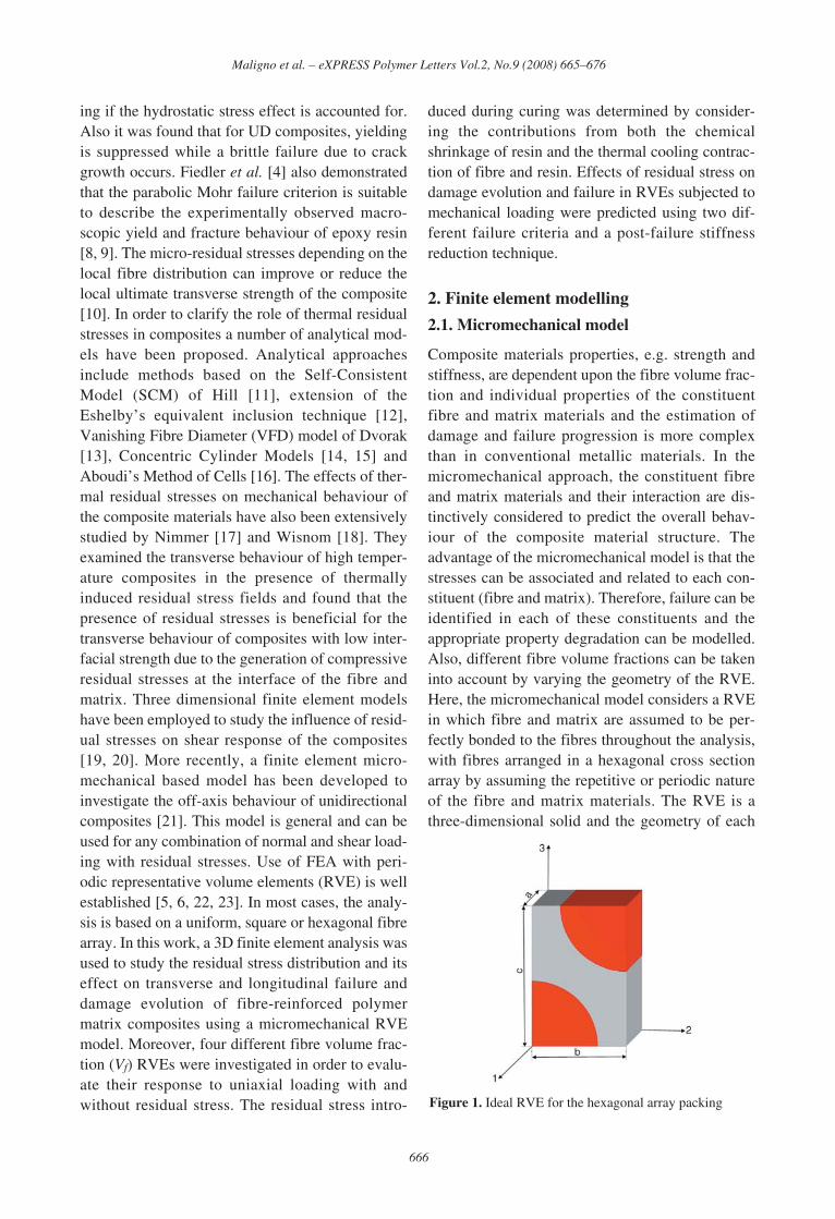
Figure 1. Ideal RVE for the hexagonal array packing
RVE depends on the fibre volume fraction [22].The RVE used in these investigations is displayedin Figure 1. The displacement constraints appliedto the finite element model displayed in Figure 1are [22]: u1 (0,2,3) = 0; u1 (a,2,3) = constant = δ1;u2 (1,0,3) = 0; u2 (1,b,3) = constant = δ2; u3 (1,2,0) =0; u3 (1,2,c) = constant = δ3; where u1 , u2 , u3
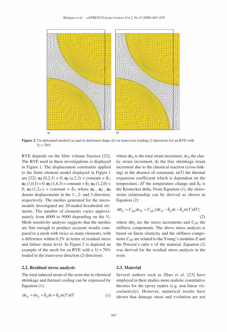
denote displacements in the 1-, 2- and 3-direction,respectively. The meshes generated for the micro-models investigated are 20-noded hexahedral ele-ments. The number of elements varies approxi-mately from 6000 to 9000 depending on the Vf.Mesh sensitivity analysis suggests that the meshesare fine enough to produce accurate results com-pared to a mesh with twice as many elements, witha difference within 0.2% in terms of residual stressand failure strain level. In Figure 2 is depicted anexample of the mesh for an RVE with a Vf = 70%loaded in the transverse direction (2-direction).
2.2. Residual stress analysis
The total induced strain of the resin due to chemicalshrinkage and thermal cooling can be expressed byEquation (1):
(1)
where dεij is the total strain increment, deij the elas-tic strain increment, ds the free shrinkage strainincrement due to the chemical reaction (cross-link-ing) in the absence of constraint, α(T) the thermalexpansion coefficient which is dependent on thetemperature, dT the temperature change and δij isthe Kronecker delta. From Equation (1), the stress-strain relationship can be derived as shown inEquation (2):
(2)where dσij are the stress increments and Cijkl thestiffness components. The above stress analysis isbased on linear elasticity and the stiffness compo-nents Cijkl are related to the Young’s modulus E andthe Poisson’s ratio ν of the material. Equation (2)was derived for the residual stress analysis in theresin.
2.3. Material
Several authors such as Zhao et al. [23] haveemployed in their studies more realistic constitutivetheories for the epoxy matrix (e.g. non linear vis-coelasticity). However, numerical results haveshown that damage onset and evolution are not
}d)(dd{dd TTsCeC ijijklijklklijklij αδ−δ−ε==σ
TTse ijijijij d)(ddd αδ+δ+=ε
667
Maligno et al. – eXPRESS Polymer Letters Vol.2, No.9 (2008) 665–676
Figure 2. Un-deformed meshed (a) and its deformed shape (b) on transverse loading (2-direction) for an RVE withVf = 70%
influenced by the stress-relaxation, induced by theviscoelastic behaviour and, the final amount ofresidual stress (after cooling) is not in general sig-nificantly affected by the viscoelastic property ofthe resin. Hence, residual stress and its effect ontransverse and longitudinal failure of UD compos-ites have been investigated considering the linear-elastic behaviour of the constituents. In particular,the materials used in this investigation are glassfibre and epoxy resin, whose properties are given in[24]. The properties of glass fibre are assumed toremain constant and independent of the tempera-ture change with Young’s modulus E = 80 GPa andPoisson’s ratio ν = 0.22, the coefficient of thermalexpansion α = 4.9·10–6/°C and the longitudinal ten-sile (σT) and compressive (σC) strength are 2150and 1450 MPa, respectively. However, for theepoxy resin, thermal transition temperatures suchas the glass transition temperature Tg stronglyaffect mechanical properties [24]. In order to repre-sent this behaviour accurately the material proper-ties of the resin are defined as a function oftemperature. The following relations are used:(a) Poisson’s ratio is assumed to be temperatureindependent (ν = 0.35).(b) To evaluate the variation of Young’s modulus Eover the temperature range from curing to roomtemperature, the total temperature range can bedivided into three regions:
– Τg – ΔΤ ≤ Τ ≤ Tg + ΔΤ, in which E variesgreatly.
– T > Tg + ΔΤ, the matrix is in liquid or rubberystate and E has a very small value.
– T < Tg – ΔΤ, the matrix is in solid state and Echanges only slightly.
For each region, the modulus is obtained using thefollowing functions given by Equations (3)–(5)[25]:
,
T < Tg – ΔΤ, (3)
,
Τg – ΔΤ ≤ Τ ≤ Tg + ΔΤ, (4)
, T > Tg + ΔΤ, (5)
with: Tg = 110°C; Tr = 23°C; ΔT = 35°C; E(Tr) =3.35 GPa; E(Tg – ΔT) = 0.7E(Tr); E(Tg + ΔT) =0.01E(Tr); k1 = 0.357; k2 = 4.249.(c) The thermal expansion coefficient α is assumedto change linearly with the temperature: α(T) =K(T – Tref) + α(Tr), with a slope given by Equa-tion (6):
(6)
where α(Tr) = 58·10–6/°C and αl = 139·10–6/°C.The longitudinal tensile (σT) and compressive (σC)strength of the resin are taken to be 80 and 120M Pa,respectively.
3. Failure criteria and damage evolutionmodel
The selection of a proper failure criterion, both formatrix and fibre, represents a very important task ofthe modelling formulation. In particular in poly-mers the yield behaviour is sensitive to hydrostaticstress and as a consequence, the yield stress in ten-sion is different from that in compression [7, 26,and 27]. Both fibre and resin are isotropic materialsand the Maximum Principal Stress theory is appli-cable to simulate damage onset and evolutionwithin the RVE (e.g. fibre/matrix debonding,matrix crack). If the stress level satisfies the failurecriterion, the fibre or matrix would crack. Final fail-ure corresponds to the rupture of the composite,which is unable to carry further load. The Maxi-mum Principal Stress failure criterion is summa-rized as shown in Equations (7) and (8):
(7)
(8)
where σmax and σmin are the Maximum and Mini-mum Principal Stresses, σt
u is the tensile strengthand σc
u is the compressive strength of the material.A modification of the von Mises criterion has alsobeen also considered to evaluate failure in thematrix. As the von Mises criterion does not predictdifferences in yield stress between tension andcompression, modifications of this criterion haveincorporated the effects of hydrostatic pressure. Ageneral form for the modified von Mises criterioncan be written as shown in Equation (9) [7]:
cuσ<σmin
tuσ<σmax
rg
rl
TT
TK
−
α−α=
)(
)(01.0)( rTETE =
⎟⎟⎠
⎞⎜⎜⎝
⎛
Δ+Δ
Δ+−−Δ−=
TT
TTTkTTETE g
g 2exp)()(
⎟⎟⎟
⎠
⎞
⎜⎜⎜
⎝
⎛
−Δ−
−−=rg
rr
TTT
TTkTETE 1exp)()(
668
Maligno et al. – eXPRESS Polymer Letters Vol.2, No.9 (2008) 665–676
(9)
It is possible to determine the constants A and B interm of the simple uniaxial tensile (σy,T) and com-pressive (σy,C) yield stresses. The modified vonMises stress criterion was suggested by Raghavaand has been shown to agree very well with experi-mental data for epoxy resin – see Equation (10) [7]:
(10)
If σy,C = σy,T this criterion reduces to the von Misescriterion. To simulate damage, it is necessary toevaluate the current stress state at each integrationpoint. Then by comparing the current stress statewith a specific failure criterion, the material proper-ties are reduced at each ‘failed’ integration point tovalues representing the particular type of damagethat has occurred [28–30]. The degradation scheme,together with the residual stress analysis was pro-grammed into a user-defined material subroutine(UMAT) interfaced with the commercial finite ele-ment code ABAQUS Standard [31]. When failureis detected the degradation is applied only on theelastic moduli by multiplying them with a discountfactor di ∈ (0, 1] (i designates the elastic modulusto which the factor is applied). Both resin and fibrewere modelled as isotropic with they the stiffnessmatrix shown in Equation (11):
(11)
The Young’s modulus E and the shear modulus Gare degraded independently by discount factor dE
and dG both initially set equal to the unity. If duringthe analysis the stress level exceed the maximumstrength allowed for matrix and/or fibre accordingto the failure criterion, the modulus E is degradedto 1% of its initial value (dE = 0.01) at the particularintegration point. The shear modulus G is reducedto 20% of the initial value (dG = 0.2) under theassumption that some shear stiffness remains due tothe friction still present on the failure plane [30].The behaviour of the matrix and the fibre wasassumed to be linear elastic until damage was pre-dicted. The response after damage occurred wasalso linear elastic but with degraded moduli.
4. Results and discussion
4.1. Residual stress
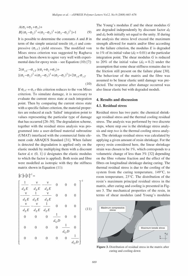
Residual stress has two parts: the chemical shrink-age residual stress and the thermal cooling residualstress. The analysis was performed by two discretesteps, where step one is the shrinkage stress analy-sis and step two is the thermal cooling stress analy-sis. The shrinkage residual stress was calculated byapplying a given amount of resin shrinkage. For theepoxy resin considered here, the linear shrinkagestrain was chosen to be 1%, which corresponds to avolumetric change of less than 3% [32] dependingon the fibre volume fraction and the effect of thefibres on longitudinal shrinkage during curing. Thethermal residual stress is due to the cooling of thesystem from the curing temperature, 149°C, toroom temperature, 23°C. The distribution of theresin’s maximum principal residual stress in thematrix, after curing and cooling is presented in Fig-ure 3. The mechanical properties of the resin, interms of shear modulus (and Young’s modulus
[ ] [ ]1
1
100000
01
0000
001
000
0001
0001
0001 −
−
⎥⎥⎥⎥⎥⎥⎥⎥⎥⎥⎥⎥⎥⎥⎥⎥⎥
⎦
⎤
⎢⎢⎢⎢⎢⎢⎢⎢⎢⎢⎢⎢⎢⎢⎢⎢⎢
⎣
⎡
ν−ν−
ν−ν−
ν−ν−
==
Dd
Dd
Dd
EdEdEd
EdEdEd
EdEdEd
SC
G
G
G
EEE
EEE
EEE
TyCy
TyCy
,,2
132
322
21
321,,
2])()()[(
))((2
σσ=σ−σ+σ−σ+σ−σ+σ+σ+σσ−σ
1])()()([
)(2
132
322
21
321
=σ−σ+σ−σ+σ−σ+σ+σ+σ
B
A
669
Maligno et al. – eXPRESS Polymer Letters Vol.2, No.9 (2008) 665–676
Figure 3. Distribution of residual stress in the matrix aftercuring and cooling-down
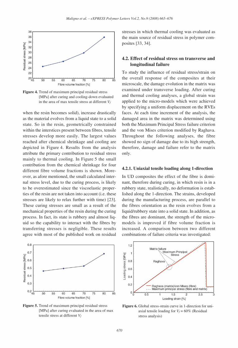
when the resin becomes solid), increase drasticallyas the material evolves from a liquid state to a solidstate. So in the resin, geometrically constrainedwithin the interstices present between fibres, tensilestresses develop more easily. The largest valuesreached after chemical shrinkage and cooling aredepicted in Figure 4. Results from the analysisattribute the primary contribution to residual stressmainly to thermal cooling. In Figure 5 the smallcontribution from the chemical shrinkage for fourdifferent fibre volume fractions is shown. More-over, as afore mentioned, the small calculated inter-nal stress level, due to the curing process, is likelyto be overestimated since the viscoelastic proper-ties of the resin are not taken into account (i.e. thesestresses are likely to relax further with time) [23].These curing stresses are small as a result of themechanical properties of the resin during the curingprocess. In fact, its state is rubbery and almost liq-uid so the capability to interact with the fibres bytransferring stresses is negligible. These resultsagree with most of the published work on residual
stresses in which thermal cooling was evaluated asthe main source of residual stress in polymer com-posites [33, 34].
4.2. Effect of residual stress on transverse andlongitudinal failure
To study the influence of residual stress/strain onthe overall response of the composites at theirmicroscale, the damage evolution in the matrix wasexamined under transverse loading. After curingand thermal cooling analyses, a global strain wasapplied to the micro-models which were achievedby specifying a uniform displacement on the RVEsfaces. At each time increment of the analysis, thedamaged area in the matrix was determined usingboth the Maximum Principal Stress failure criterionand the von Mises criterion modified by Raghava.Throughout the following analyses, the fibreshowed no sign of damage due to its high strength,therefore, damage and failure refer to the matrixonly.
4.2.1. Uniaxial tensile loading along 1-direction
In UD composites the effect of the fibre is domi-nant, therefore during curing, in which resin is in arubbery state, realistically, no deformation is estab-lished along the 1-direction. The strains, developedduring the manufacturing process, are parallel tothe fibres orientation as the resin evolves from aliquid/rubbery state into a solid state. In addition, asthe fibres are dominant, the strength of the micro-models is improved if fibre volume fraction isincreased. A comparison between two differentcombinations of failure criteria was investigated:
670
Maligno et al. – eXPRESS Polymer Letters Vol.2, No.9 (2008) 665–676
Figure 4. Trend of maximum principal residual stress[MPa] after curing and cooling-down evaluatedin the area of max tensile stress at different Vf
Figure 5. Trend of maximum principal residual stress[MPa] after curing evaluated in the area of maxtensile stress at different Vf
Figure 6. Global stress-strain curve in 1-direction for uni-axial tensile loading for Vf = 60% (Residualstress analysis)
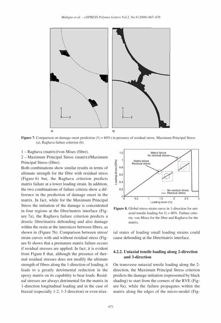
1 – Raghava (matrix)/von Mises (fibre).2 – Maximum Principal Stress (matrix)/MaximumPrincipal Stress (fibre).Both combinations show similar results in terms ofultimate strength for the fibre with residual stress(Figure 6) but, the Raghava criterion predictsmatrix failure at a lower loading strain. In addition,the two combinations of failure criteria show a dif-ference in the prediction of damage onset in thematrix. In fact, while for the Maximum PrincipalStress the initiation of the damage is concentratedin four regions at the fibre/matrix interface (Fig-ure 7a), the Raghava failure criterion predicts adrastic fibre/matrix debonding and also damagewithin the resin at the interstices between fibres, asshown in (Figure 7b). Comparison between stress/strain curves with and without residual stress (Fig-ure 8) shows that a premature matrix failure occursif residual stresses are applied. In fact, it is evidentfrom Figure 8 that, although the presence of ther-mal residual stresses does not modify the ultimatestrength of fibres along the 1-direction of loading, itleads to a greatly detrimental reduction in theepoxy matrix on its capability to bear loads. Resid-ual stresses are always detrimental for the matrix in1-direction longitudinal loading and in the case ofbiaxial (especially 1-2, 1-3 direction) or even triax-
ial states of loading small loading strains couldcause debonding at the fibre/matrix interface.
4.2.2. Uniaxial tensile loading along 2-directionand 3-direction
On transverse uniaxial tensile loading along the 2-direction, the Maximum Principal Stress criterionpredicts the damage initiation (represented by blackshading) to start from the corners of the RVE (Fig-ure 9a), while the failure propagates within thematrix along the edges of the micro-model (Fig-
671
Maligno et al. – eXPRESS Polymer Letters Vol.2, No.9 (2008) 665–676
Figure 7. Comparison on damage onset prediction (Vf = 60%) in presence of residual stress. Maximum Principal Stress(a), Raghava failure criterion (b).
Figure 8. Global stress-strain curve in 1-direction for uni-axial tensile loading for Vf = 60%. Failure crite-ria: von Mises for the fibre and Raghava for thematrix.
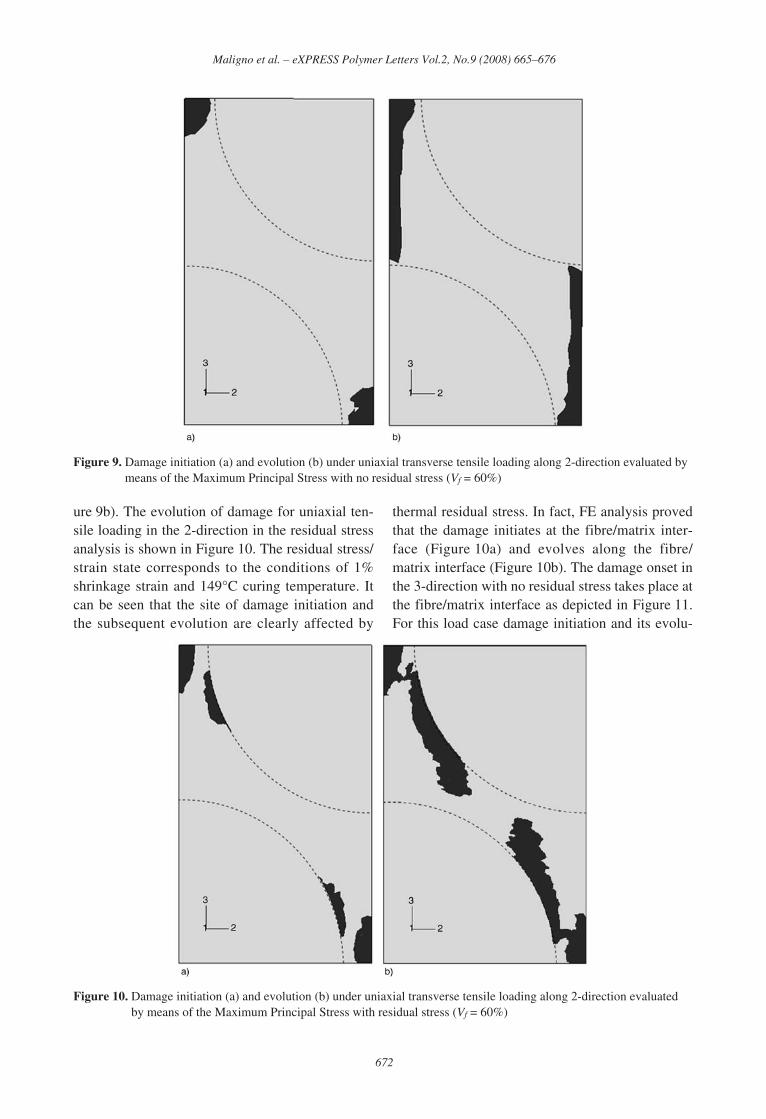
ure 9b). The evolution of damage for uniaxial ten-sile loading in the 2-direction in the residual stressanalysis is shown in Figure 10. The residual stress/strain state corresponds to the conditions of 1%shrinkage strain and 149°C curing temperature. Itcan be seen that the site of damage initiation andthe subsequent evolution are clearly affected by
thermal residual stress. In fact, FE analysis provedthat the damage initiates at the fibre/matrix inter-face (Figure 10a) and evolves along the fibre/matrix interface (Figure 10b). The damage onset inthe 3-direction with no residual stress takes place atthe fibre/matrix interface as depicted in Figure 11.For this load case damage initiation and its evolu-
672
Maligno et al. – eXPRESS Polymer Letters Vol.2, No.9 (2008) 665–676
Figure 9. Damage initiation (a) and evolution (b) under uniaxial transverse tensile loading along 2-direction evaluated bymeans of the Maximum Principal Stress with no residual stress (Vf = 60%)
Figure 10. Damage initiation (a) and evolution (b) under uniaxial transverse tensile loading along 2-direction evaluatedby means of the Maximum Principal Stress with residual stress (Vf = 60%)
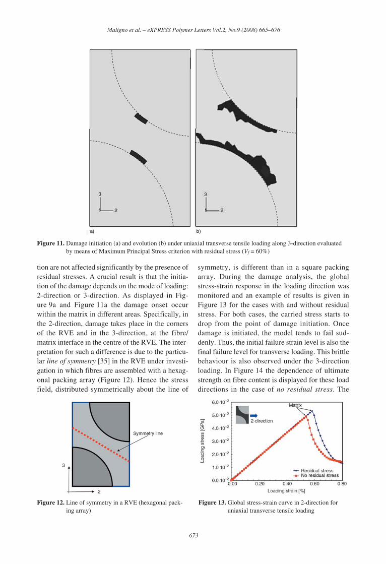
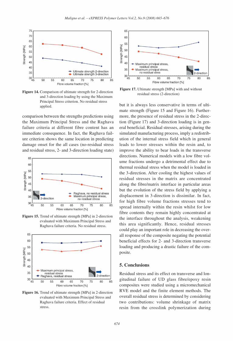
tion are not affected significantly by the presence ofresidual stresses. A crucial result is that the initia-tion of the damage depends on the mode of loading:2-direction or 3-direction. As displayed in Fig-ure 9a and Figure 11a the damage onset occurwithin the matrix in different areas. Specifically, inthe 2-direction, damage takes place in the cornersof the RVE and in the 3-direction, at the fibre/matrix interface in the centre of the RVE. The inter-pretation for such a difference is due to the particu-lar line of symmetry [35] in the RVE under investi-gation in which fibres are assembled with a hexag-onal packing array (Figure 12). Hence the stressfield, distributed symmetrically about the line of
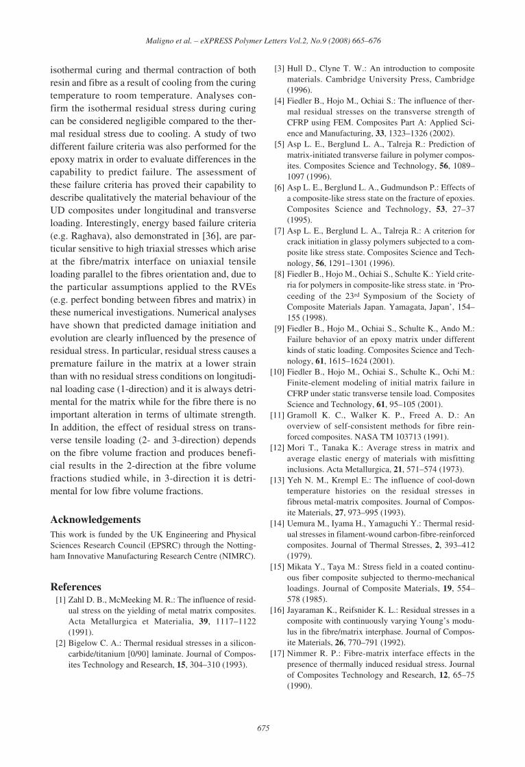
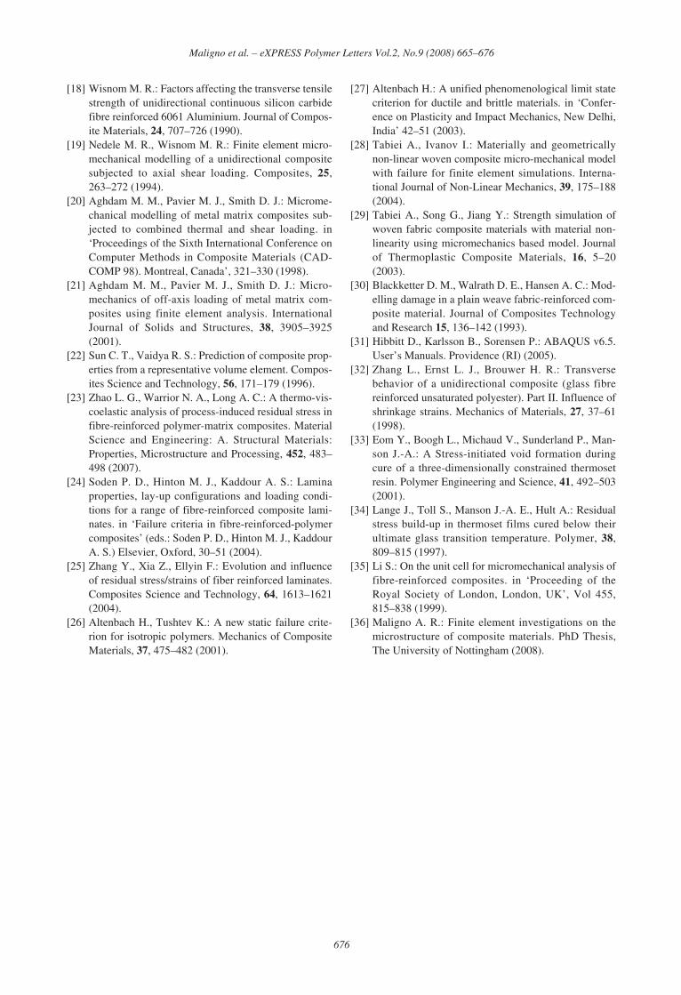
symmetry, is different than in a square packingarray. During the damage analysis, the globalstress-strain response in the loading direction wasmonitored and an example of results is given inFigure 13 for the cases with and without residualstress. For both cases, the carried stress starts todrop from the point of damage initiation. Oncedamage is initiated, the model tends to fail sud-denly. Thus, the initial failure strain level is also thefinal failure level for transverse loading. This brittlebehaviour is also observed under the 3-directionloading. In Figure 14 the dependence of ultimatestrength on fibre content is displayed for these loaddirections in the case of no residual stress. The
673
Maligno et al. – eXPRESS Polymer Letters Vol.2, No.9 (2008) 665–676
Figure 11. Damage initiation (a) and evolution (b) under uniaxial transverse tensile loading along 3-direction evaluatedby means of Maximum Principal Stress criterion with residual stress (Vf = 60%)
Figure 12. Line of symmetry in a RVE (hexagonal pack-ing array)
Figure 13. Global stress-strain curve in 2-direction foruniaxial transverse tensile loading
comparison between the strengths predictions usingthe Maximum Principal Stress and the Raghavafailure criteria at different fibre content has animmediate consequence. In fact, the Raghava fail-ure criterion shows the same location in predictingdamage onset for the all cases (no-residual stressand residual stress, 2- and 3-direction loading state)
but it is always less conservative in terms of ulti-mate strength (Figure 15 and Figure 16). Further-more, the presence of residual stress in the 2-direc-tion (Figure 17) and 3-direction loading is in gen-eral beneficial. Residual stresses, arising during thesimulated manufacturing process, imply a redistrib-ution of the internal stress field which in generalleads to lower stresses within the resin and, toimprove the ability to bear loads in the transversedirections. Numerical models with a low fibre vol-ume fractions undergo a detrimental effect due tothermal residual stress when the model is loaded inthe 3-direction. After cooling the highest values ofresidual stresses in the matrix are concentratedalong the fibre/matrix interface in particular areasbut the evolution of the stress field by applying adisplacement in 3-direction is dissimilar. In fact,for high fibre volume fractions stresses tend tospread internally within the resin whilst for lowfibre contents they remain highly concentrated atthe interface throughout the analysis, weakeningthis area significantly. Hence, residual stressescould play an important role in decreasing the over-all response of the composite negating the potentialbeneficial effects for 2- and 3-direction transverseloading and producing a drastic failure of the com-posite.
5. Conclusions
Residual stress and its effect on transverse and lon-gitudinal failure of UD glass fibre/epoxy resincomposites were studied using a micromechanicalRVE model and the finite element methods. Theoverall residual stress is determined by consideringtwo contributions: volume shrinkage of matrixresin from the crosslink polymerization during
674
Maligno et al. – eXPRESS Polymer Letters Vol.2, No.9 (2008) 665–676
Figure 14. Comparison of ultimate strength for 2-directionand 3-direction loading by using the MaximumPrincipal Stress criterion. No residual stressapplied.
Figure 15. Trend of ultimate strength [MPa] in 2-directionevaluated with Maximum Principal Stress andRaghava failure criteria. No residual stress.
Figure 16. Trend of ultimate strength [MPa] in 2-directionevaluated with Maximum Principal Stress andRaghava failure criteria. Effect of residualstress.
Figure 17. Ultimate strength [MPa] with and withoutresidual stress (2-direction)
isothermal curing and thermal contraction of bothresin and fibre as a result of cooling from the curingtemperature to room temperature. Analyses con-firm the isothermal residual stress during curingcan be considered negligible compared to the ther-mal residual stress due to cooling. A study of twodifferent failure criteria was also performed for theepoxy matrix in order to evaluate differences in thecapability to predict failure. The assessment ofthese failure criteria has proved their capability todescribe qualitatively the material behaviour of theUD composites under longitudinal and transverseloading. Interestingly, energy based failure criteria(e.g. Raghava), also demonstrated in [36], are par-ticular sensitive to high triaxial stresses which ariseat the fibre/matrix interface on uniaxial tensileloading parallel to the fibres orientation and, due tothe particular assumptions applied to the RVEs(e.g. perfect bonding between fibres and matrix) inthese numerical investigations. Numerical analyseshave shown that predicted damage initiation andevolution are clearly influenced by the presence ofresidual stress. In particular, residual stress causes apremature failure in the matrix at a lower strainthan with no residual stress conditions on longitudi-nal loading case (1-direction) and it is always detri-mental for the matrix while for the fibre there is noimportant alteration in terms of ultimate strength.In addition, the effect of residual stress on trans-verse tensile loading (2- and 3-direction) dependson the fibre volume fraction and produces benefi-cial results in the 2-direction at the fibre volumefractions studied while, in 3-direction it is detri-mental for low fibre volume fractions.
AcknowledgementsThis work is funded by the UK Engineering and PhysicalSciences Research Council (EPSRC) through the Notting-ham Innovative Manufacturing Research Centre (NIMRC).
References[1] Zahl D. B., McMeeking M. R.: The influence of resid-
ual stress on the yielding of metal matrix composites.Acta Metallurgica et Materialia, 39, 1117–1122(1991).
[2] Bigelow C. A.: Thermal residual stresses in a silicon-carbide/titanium [0/90] laminate. Journal of Compos-ites Technology and Research, 15, 304–310 (1993).
[3] Hull D., Clyne T. W.: An introduction to compositematerials. Cambridge University Press, Cambridge(1996).
[4] Fiedler B., Hojo M., Ochiai S.: The influence of ther-mal residual stresses on the transverse strength ofCFRP using FEM. Composites Part A: Applied Sci-ence and Manufacturing, 33, 1323–1326 (2002).
[5] Asp L. E., Berglund L. A., Talreja R.: Prediction ofmatrix-initiated transverse failure in polymer compos-ites. Composites Science and Technology, 56, 1089–1097 (1996).
[6] Asp L. E., Berglund L. A., Gudmundson P.: Effects ofa composite-like stress state on the fracture of epoxies.Composites Science and Technology, 53, 27–37(1995).
[7] Asp L. E., Berglund L. A., Talreja R.: A criterion forcrack initiation in glassy polymers subjected to a com-posite like stress state. Composites Science and Tech-nology, 56, 1291–1301 (1996).
[8] Fiedler B., Hojo M., Ochiai S., Schulte K.: Yield crite-ria for polymers in composite-like stress state. in ‘Pro-ceeding of the 23rd Symposium of the Society ofComposite Materials Japan. Yamagata, Japan’, 154–155 (1998).
[9] Fiedler B., Hojo M., Ochiai S., Schulte K., Ando M.:Failure behavior of an epoxy matrix under differentkinds of static loading. Composites Science and Tech-nology, 61, 1615–1624 (2001).
[10] Fiedler B., Hojo M., Ochiai S., Schulte K., Ochi M.:Finite-element modeling of initial matrix failure inCFRP under static transverse tensile load. CompositesScience and Technology, 61, 95–105 (2001).
[11] Gramoll K. C., Walker K. P., Freed A. D.: Anoverview of self-consistent methods for fibre rein-forced composites. NASA TM 103713 (1991).
[12] Mori T., Tanaka K.: Average stress in matrix andaverage elastic energy of materials with misfittinginclusions. Acta Metallurgica, 21, 571–574 (1973).
[13] Yeh N. M., Krempl E.: The influence of cool-downtemperature histories on the residual stresses infibrous metal-matrix composites. Journal of Compos-ite Materials, 27, 973–995 (1993).
[14] Uemura M., Iyama H., Yamaguchi Y.: Thermal resid-ual stresses in filament-wound carbon-fibre-reinforcedcomposites. Journal of Thermal Stresses, 2, 393–412(1979).
[15] Mikata Y., Taya M.: Stress field in a coated continu-ous fiber composite subjected to thermo-mechanicalloadings. Journal of Composite Materials, 19, 554–578 (1985).
[16] Jayaraman K., Reifsnider K. L.: Residual stresses in acomposite with continuously varying Young’s modu-lus in the fibre/matrix interphase. Journal of Compos-ite Materials, 26, 770–791 (1992).
[17] Nimmer R. P.: Fibre-matrix interface effects in thepresence of thermally induced residual stress. Journalof Composites Technology and Research, 12, 65–75(1990).
675
Maligno et al. – eXPRESS Polymer Letters Vol.2, No.9 (2008) 665–676
[18] Wisnom M. R.: Factors affecting the transverse tensilestrength of unidirectional continuous silicon carbidefibre reinforced 6061 Aluminium. Journal of Compos-ite Materials, 24, 707–726 (1990).
[19] Nedele M. R., Wisnom M. R.: Finite element micro-mechanical modelling of a unidirectional compositesubjected to axial shear loading. Composites, 25,263–272 (1994).
[20] Aghdam M. M., Pavier M. J., Smith D. J.: Microme-chanical modelling of metal matrix composites sub-jected to combined thermal and shear loading. in‘Proceedings of the Sixth International Conference onComputer Methods in Composite Materials (CAD-COMP 98). Montreal, Canada’, 321–330 (1998).
[21] Aghdam M. M., Pavier M. J., Smith D. J.: Micro-mechanics of off-axis loading of metal matrix com-posites using finite element analysis. InternationalJournal of Solids and Structures, 38, 3905–3925(2001).
[22] Sun C. T., Vaidya R. S.: Prediction of composite prop-erties from a representative volume element. Compos-ites Science and Technology, 56, 171–179 (1996).
[23] Zhao L. G., Warrior N. A., Long A. C.: A thermo-vis-coelastic analysis of process-induced residual stress infibre-reinforced polymer-matrix composites. MaterialScience and Engineering: A. Structural Materials:Properties, Microstructure and Processing, 452, 483–498 (2007).
[24] Soden P. D., Hinton M. J., Kaddour A. S.: Laminaproperties, lay-up configurations and loading condi-tions for a range of fibre-reinforced composite lami-nates. in ‘Failure criteria in fibre-reinforced-polymercomposites’ (eds.: Soden P. D., Hinton M. J., KaddourA. S.) Elsevier, Oxford, 30–51 (2004).
[25] Zhang Y., Xia Z., Ellyin F.: Evolution and influenceof residual stress/strains of fiber reinforced laminates.Composites Science and Technology, 64, 1613–1621(2004).
[26] Altenbach H., Tushtev K.: A new static failure crite-rion for isotropic polymers. Mechanics of CompositeMaterials, 37, 475–482 (2001).
[27] Altenbach H.: A unified phenomenological limit statecriterion for ductile and brittle materials. in ‘Confer-ence on Plasticity and Impact Mechanics, New Delhi,India’ 42–51 (2003).
[28] Tabiei A., Ivanov I.: Materially and geometricallynon-linear woven composite micro-mechanical modelwith failure for finite element simulations. Interna-tional Journal of Non-Linear Mechanics, 39, 175–188(2004).
[29] Tabiei A., Song G., Jiang Y.: Strength simulation ofwoven fabric composite materials with material non-linearity using micromechanics based model. Journalof Thermoplastic Composite Materials, 16, 5–20(2003).
[30] Blackketter D. M., Walrath D. E., Hansen A. C.: Mod-elling damage in a plain weave fabric-reinforced com-posite material. Journal of Composites Technologyand Research 15, 136–142 (1993).
[31] Hibbitt D., Karlsson B., Sorensen P.: ABAQUS v6.5.User’s Manuals. Providence (RI) (2005).
[32] Zhang L., Ernst L. J., Brouwer H. R.: Transversebehavior of a unidirectional composite (glass fibrereinforced unsaturated polyester). Part II. Influence ofshrinkage strains. Mechanics of Materials, 27, 37–61(1998).
[33] Eom Y., Boogh L., Michaud V., Sunderland P., Man-son J.-A.: A Stress-initiated void formation duringcure of a three-dimensionally constrained thermosetresin. Polymer Engineering and Science, 41, 492–503(2001).
[34] Lange J., Toll S., Manson J.-A. E., Hult A.: Residualstress build-up in thermoset films cured below theirultimate glass transition temperature. Polymer, 38,809–815 (1997).
[35] Li S.: On the unit cell for micromechanical analysis offibre-reinforced composites. in ‘Proceeding of theRoyal Society of London, London, UK’, Vol 455,815–838 (1999).
[36] Maligno A. R.: Finite element investigations on themicrostructure of composite materials. PhD Thesis,The University of Nottingham (2008).
676
Maligno et al. – eXPRESS Polymer Letters Vol.2, No.9 (2008) 665–676