finisher-f1/ saddle finisher-f2 service manual · finisher-f1/saddle finisher-f2 rev. 0 july 2000...
TRANSCRIPT
COPYRIGHT © 2000 CANON INC. FINISHER-F1/SADDLE FINISHER-F2 REV. 0 JULY 2000 PRINTED IN JAPAN (IMPRIME AU JAPON)
FINISHER-F1/SADDLE FINISHER-F2
SERVICEMANUALREVISION 0
JULY 2000 FY8-13GU-000

COPYRIGHT © 2000 CANON INC. FINISHER-F1/SADDLE FINISHER-F2 REV. 0 JULY 2000 PRINTED IN JAPAN (IMPRIME AU JAPON)
IMPORTANT
THE INFORMATION CONTAINED HEREIN PUBLISHED BY CANON, INC., JAPAN.SPECIFICATIONS AND OTHER INFORMATION CONTAINED HEREIN MAY DIFFER SLIGHTLYFROM ACTUAL MACHINE VALUES OR THOSE FOUND IN ADVERTISING AND OTHERPRINTED MATTER.
ANY QUESTIONS REGARDING INFORMATION CONTAINED HEREIN SHOULD BE DIRECTEDTO THE COPIER SERVICE DEPARTMENT OF THE COMPANY.
COPYRIGHT © 2000 CANON INC.
Printed in JapanImprimé au Japon
Use of this manual should be strictly super-
vised to avoid disclosure of confidential in-
formation.
Prepared by
OFFICE IMAGING PRODUCTS TECHNICAL SUPPORT DEPARTMENT 3OFFICE IMAGING PRODUCTS TECHNICAL SUPPORT DIVISION
CANON INC.
5-1, Hakusan 7-chome, Toride-shi Ibaraki, 302-8501 Japan
COPYRIGHT © 2000 CANON INC. FINISHER-F1/SADDLE FINISHER-F2 REV. 0 JULY 2000 PRINTED IN JAPAN (IMPRIME AU JAPON) i
This Service Manual contains basic data and figures for the Finisher-F1/Saddle Fin-isher-F2 needed to service the machine in the field.
This manual comprises the following chapters:
Chapter 1 “General Description” introduces the finisher’s features, specifications, andnames of parts, and shows how to operate the finisher.
Chapter 2 “Finisher Unit Basic Operation” discusses the principles of operation used forthe finisher mechanical and electrical systems. It also explains the timing atwhich these systems are operated.
Chapter 3 “Saddle Finisher Unit Basic Operation” discusses the principles of operationused for the saddle stitcher unit’s mechanical and electrical systems. It alsoexplains the timing at which these systems are operated.
Chapter 4 “Puncher (option) Unit Basic Operation” discusses the principles of operationused for the puncher unit’s mechanical and electrical systems. It also explainsthe timing at which these systems are operated.
Chapter 5 “Mechanical System” discusses how the finisher is constructed mechanically,and shows how it may be disassembled/assembled and adjusted.
Chapter 6 “Maintenance and Inspection” provides tables of periodically replaced partsand consumables and durables, together with a scheduled servicing chart.
Chapter 7 “Troubleshooting” shows how to troubleshoot possible faults and gives electri-cal parts arrangement diagrams, LED/check pin diagrams by PCB, and selfdiagnosis tables.
“Appendix” contains diagrams showing tables of signals, overall circuit dia-grams and tables of solvents/oils.
Descriptions regarding installation are not mentioned in this Service Manual as theFinisher-F1/Saddle Finisher-F2’s packing boxes contain Installation Procedures.
The descriptions in this Service Manual are subject to change without notice for prod-uct improvement or other purposes, and major changes will be communicated in the formof Service Information bulletins.
All service persons are expected to have a good understanding of the contents of thisService Manual and all relevant Service Information bulletins, and be able to identify andisolate faults in the machine.
INTRODUCTION

COPYRIGHT © 2000 CANON INC. FINISHER-F1/SADDLE FINISHER-F2 REV. 0 JULY 2000 PRINTED IN JAPAN (IMPRIME AU JAPON)i i
COPYRIGHT © 2000 CANON INC. FINISHER-F1/SADDLE FINISHER-F2 REV. 0 JULY 2000 PRINTED IN JAPAN (IMPRIME AU JAPON) i i i
CHAPTER 1 GENERAL DESCRIPTION
CONTENTS
I. FEATURES ..................................1-1II. SPECIFICATIONS .......................1-2
A. Specifications ...........................1-2B. Cross Section ...........................1-9
III. Using the Machine .................... 1-12A. Removing Paper Jams from
the Finisher Unit .....................1-12B. Supplying the Finisher Unit
with Staples ............................1-13C. Removing Staple Jams from
the Finisher Unit .....................1-15D. Removing Paper Jams from
the Saddle Stitcher Unit(Saddle Finisher-F2) ..............1-16
E. Supplying the Saddle StitcherUnit with Staples(Saddle Finisher-F2) ..............1-18
F. Removing Staple Jams fromthe Saddle Stitcher Unit(Saddle Finisher-F2) ..............1-19
G. Removing Paper Jams fromthe Puncher Unit (option) ........1-21
H. Removing Punched Scrap fromthe Puncher Unit (option) ...... 1-22
IV. MAINTENANCE BY THEUSER ........................................ 1-23
A. Maintenance by the User ...... 1-23
I. BASIC OPERATION ....................2-1A. Outline ......................................2-1B. Outline of Electrical
Circuitry ....................................2-2C. Inputs to and Outputs from the
Finisher Controller PCB............2-4II. FEED/DRIVE SYSTEM ............ 2-10
A. Outline ................................... 2-10B. Type of Delivery Paths ........... 2-15C. Feeding and Delivering.......... 2-18
D. Job Offset .............................. 2-21E. Staple Operation.................... 2-24F. Stapler Unit ............................ 2-32G. Tray Operation ....................... 2-38H. Detecting the Height of
Stack on the Tray ................... 2-40I. Shutter Operation .................. 2-42J. Buffer Path Operation ............ 2-46K. Detecting Jams ...................... 2-51
III. POWER SUPPLY SYSTEM ...... 2-56
CHAPTER 2 FINISHER UNIT BASIC OPERATION
COPYRIGHT © 2000 CANON INC. FINISHER-F1/SADDLE FINISHER-F2 REV. 0 JULY 2000 PRINTED IN JAPAN (IMPRIME AU JAPON)i v
I. BASIC OPERATION ....................3-1A. Outline ......................................3-1B. Electrical Circuitry .....................3-2C. Inputs to and Outputs from the
Saddle Stitcher ControllerPCB ..........................................3-3
II. FEEDING/DRIVE SYSTEM .........3-8A. Outline ......................................3-8
III. PAPER OUTPUTMECHANISM ............................ 3-14
A. Outline ................................... 3-14B. Controlling the Inlet
Flappers ................................. 3-17
C. Controlling the Movement ofSheets.................................... 3-21
D. Aligning the Sheets ............... 3-23E. Controlling the Phase of the
Crescent Roller .......................3-26IV. STITCHING SYSTEM ...............3-28V. FOLDING/DELIVERY
SYSTEM ................................... 3-31VI. CHECKING FOR A JAM ........... 3-38VII. POWER SUPPLY ...................... 3-43
CHAPTER 3 SADDLE STITCHER UNIT
BASIC OPERATION
I. BASIC OPERATION ....................4-1A. Outline ......................................4-1B. Inputs to and Outputs from
Punch Driver PCB ....................4-2II. PUNCH OPERATION ..................4-5
A. Outline ......................................4-5B. PUNCH OPERATION ..............4-7C. Horizontal Registration
Operation ............................... 4-11III. POWER SUPPLY SYSTEM ...... 4-14
I. FINISHER UNIT ...........................5-1A. Externals and Controls .............5-1B. FEEDING SYSTEM ..................5-8C. PCBs...................................... 5-12
II. SADDLE STITCHER UNIT ....... 5-13A. Externals and Controls .......... 5-13
B. SADDLE UNIT ....................... 5-17C. PCBs...................................... 5-27
III. PUNCHER UNIT (OPTION) ..... 5-28A. Externals and Controls .......... 5-28B. Puncher Driver System.......... 5-29C. PCBs...................................... 5-40
CHAPTER 5 MECHANICAL CONSTRUCTION
CHAPTER 4 PUNCHER UNIT (OPTION)
BASIC OPERATION
COPYRIGHT © 2000 CANON INC. FINISHER-F1/SADDLE FINISHER-F2 REV. 0 JULY 2000 PRINTED IN JAPAN (IMPRIME AU JAPON) v
I. ADJUSTMENTS ..........................7-1A. Electrical System
(finisher unit) .............................7-1B. Electrical System
(saddle stitcher unit) .................7-6C. Electrical System
(puncher unit (option)) ..............7-9II. ARRANGEMENT OF
ELECTRICAL PARTS ............... 7-11A. Finisher Unit .......................... 7-11B. Saddle Stitcher Unit ............... 7-17C. Puncher Unit (option) ............ 7-23
D. Light-Emitting Diodes (LED)and Check Pins by PCB .........7-27
III. TROUBLESHOOTING ...............7-29A. Finisher Unit ...........................7-29B. Saddle Stitcher Unit ................7-39C. Puncher Unit (option)..............7-46
IV. SELF-DIAGNOSIS.....................7-47A. Finisher Unit ...........................7-47B. Saddle Stitcher Unit ................7-49C. Puncher Unit (option)..............7-51D. Alarm ......................................7-52E. Host Machine I/O Notations ....7-54
CHAPTER 7 TROUBLESHOOTING
APPENDIX
A. FINISHER UNIT GENERALTIMING CHART .......................... A-1
B. SADDLE STITCHER UNITGENERAL TIMING CHART ........ A-2
C. PUNCHER UNIT (option)GENERAL TIMING CHART ........ A-3
D. SIGNAL ANDABBREVIATIONS ....................... A-4
E. FINISHER UNIT CIRCUITDIAGRAM ................................... A-5
F. SADDLE STITCHER UNITCIRCUIT DIAGRAM ................. A-19
G. PUNCHER UNIT (option)CIRCUIT DIAGRAM ................. A-29
H. SOLVENTS AND OILS ............. A-38
CHAPTER 6 MAINTENANCE AND INSPECTION
I. PERIODICALLY REPLACEDPARTS ..........................................6-1
A. Finisher Unit .............................6-1B. Saddle Stitcher Unit ..................6-1C. Puncher Unit (option) ...............6-1
II. CONSUMABLES ANDDURABLES..................................6-2
A. Finisher Unit .............................6-2B. Saddle Stitcher Unit ..................6-2C. Puncher Unit (option) ...............6-2
III. PERIODICAL SERVICING ..........6-2

COPYRIGHT © 2000 CANON INC. FINISHER-F1/SADDLE FINISHER-F2 REV. 0 JULY 2000 PRINTED IN JAPAN (IMPRIME AU JAPON)
CHAPTER 1
GENERAL DESCRIPTION
I. FEATURES ..................................1-1II. SPECIFICATIONS .......................1-2
A. Specifications .............................1-2B. Cross Section .............................1-9
III. Using the Machine .................... 1-12A. Removing Paper Jams from the
Finisher Unit ............................ 1-12B. Supplying the Finisher Unit with
Staples .................................... 1-13C. Removing Staple Jams from the
Finisher Unit ............................ 1-15D. Removing Paper Jams from the
Saddle Stitcher Unit(Saddle Finisher-F2) ............... 1-16
E. Supplying the Saddle Stitcher Unitwith Staples(Saddle Finisher-F2) ............... 1-18
F. Removing Staple Jams from theSaddle Stitcher Unit(Saddle Finisher-F2) ............... 1-19
G. Removing Paper Jams from thePuncher Unit (option) .............. 1-21
H. Removing Punched Scrap from thePuncher Unit (option) .............. 1-22
IV. MAINTENANCE BY THEUSER ........................................ 1-23
A. Maintenance by the User ........ 1-23

COPYRIGHT © 2000 CANON INC. FINISHER-F1/SADDLE FINISHER-F2 REV. 0 JULY 2000 PRINTED IN JAPAN (IMPRIME AU JAPON) 1-1
CHAPTER 1 GENERAL DESCRIPTION
I. FEATURES
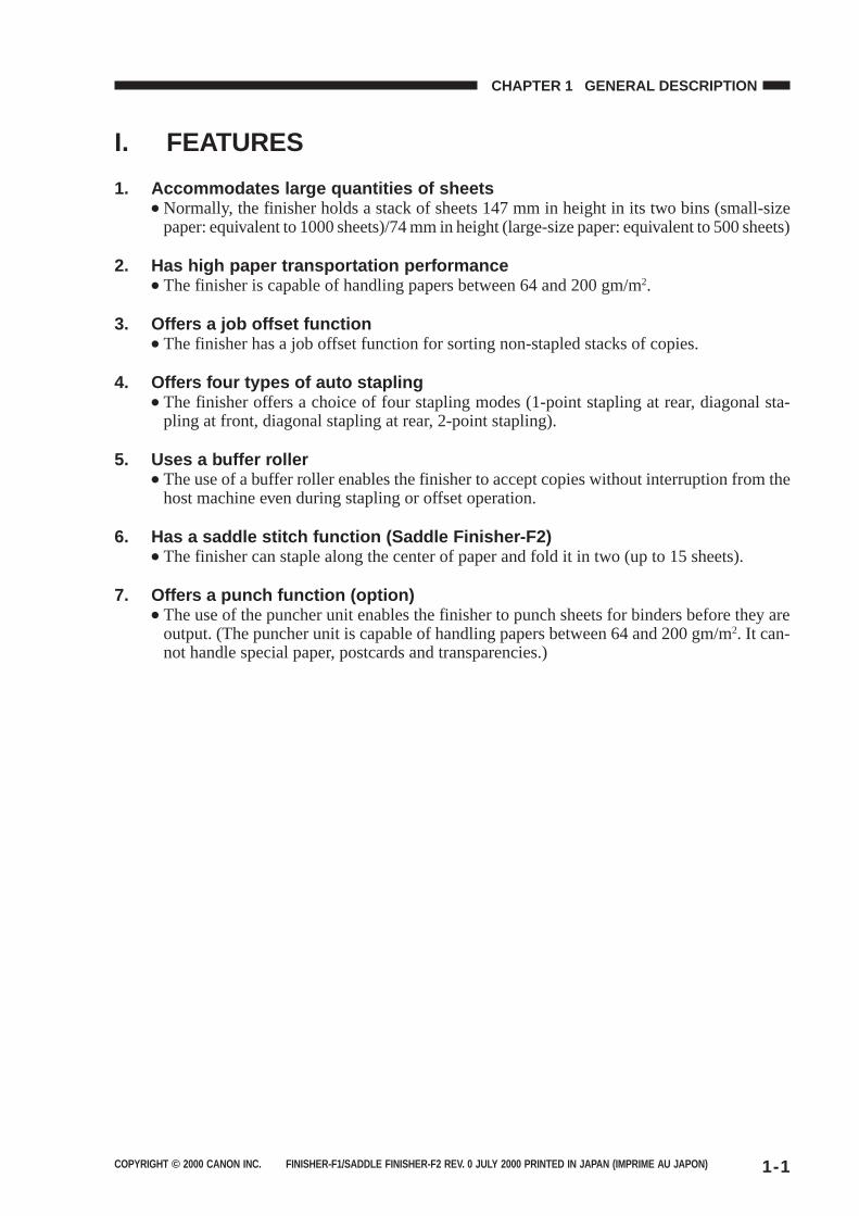
1. Accommodates large quantities of sheets● Normally, the finisher holds a stack of sheets 147 mm in height in its two bins (small-size
paper: equivalent to 1000 sheets)/74 mm in height (large-size paper: equivalent to 500 sheets)
2. Has high paper transportation performance● The finisher is capable of handling papers between 64 and 200 gm/m2.
3. Offers a job offset function● The finisher has a job offset function for sorting non-stapled stacks of copies.
4. Offers four types of auto stapling● The finisher offers a choice of four stapling modes (1-point stapling at rear, diagonal sta-
pling at front, diagonal stapling at rear, 2-point stapling).
5. Uses a buffer roller● The use of a buffer roller enables the finisher to accept copies without interruption from the
host machine even during stapling or offset operation.
6. Has a saddle stitch function (Saddle Finisher-F2)● The finisher can staple along the center of paper and fold it in two (up to 15 sheets).
7. Offers a punch function (option)● The use of the puncher unit enables the finisher to punch sheets for binders before they are
output. (The puncher unit is capable of handling papers between 64 and 200 gm/m2. It can-not handle special paper, postcards and transparencies.)
COPYRIGHT © 2000 CANON INC. FINISHER-F1/SADDLE FINISHER-F2 REV. 0 JULY 2000 PRINTED IN JAPAN (IMPRIME AU JAPON)1-2
CHAPTER 1 GENERAL DESCRIPTION
Description
Trays 1 and 2: by lifting tray
Face-downFace-up
AB: A3, A4, A4R, A5, A5R, B4, B5, B5R, postcardInch: 279 × 432 mm (11″ × 17″), LGL, LTR, LTRR, STMT, STMTR
64 to 200 g/m2
Trays 1 and 2
Non-sort: trays 1 and 2Sort: trays 1 and 2Staple: trays 1 and 2
Non staple sort Small-size Tray 1: 147 mm/5.79 in high (1000 sheets) (Note 2)
(Note 1) Tray 2: 147 mm/5.79 in high (1000 sheets) (Note 2)
Large-size Tray 1: 74 mm/2.91 in high (500 sheets)(Note 1) Tray 2: 74 mm/2.91 in high (500 sheets)
Staple sort Small-size Tray 1: 110 mm high/30 sets (750 sheets) (Note 2)
(Note 1) : 4.33 in high/30 sets (750 sheets) (Note 2)
Tray 2: 110 mm high/30 sets (750 sheets) (Note 2)
: 4.33 in high/30 sets (750 sheets) (Note 2)
Large-size Tray 1: 74 mm high/30 sets (500 sheets)(Note 1) : 2.91 in high/30 sets (500 sheets)
Tray 2: 74 mm high/30 sets (500 sheets): 2.91 in high/30 sets (500 sheets)
Size mixing: 44 mm or less (300 sheets)Stapling: 22 mm or less (150 sheets/30 sets)
Face-down/face-up
II. SPECIFICATIONS
A. Specifications
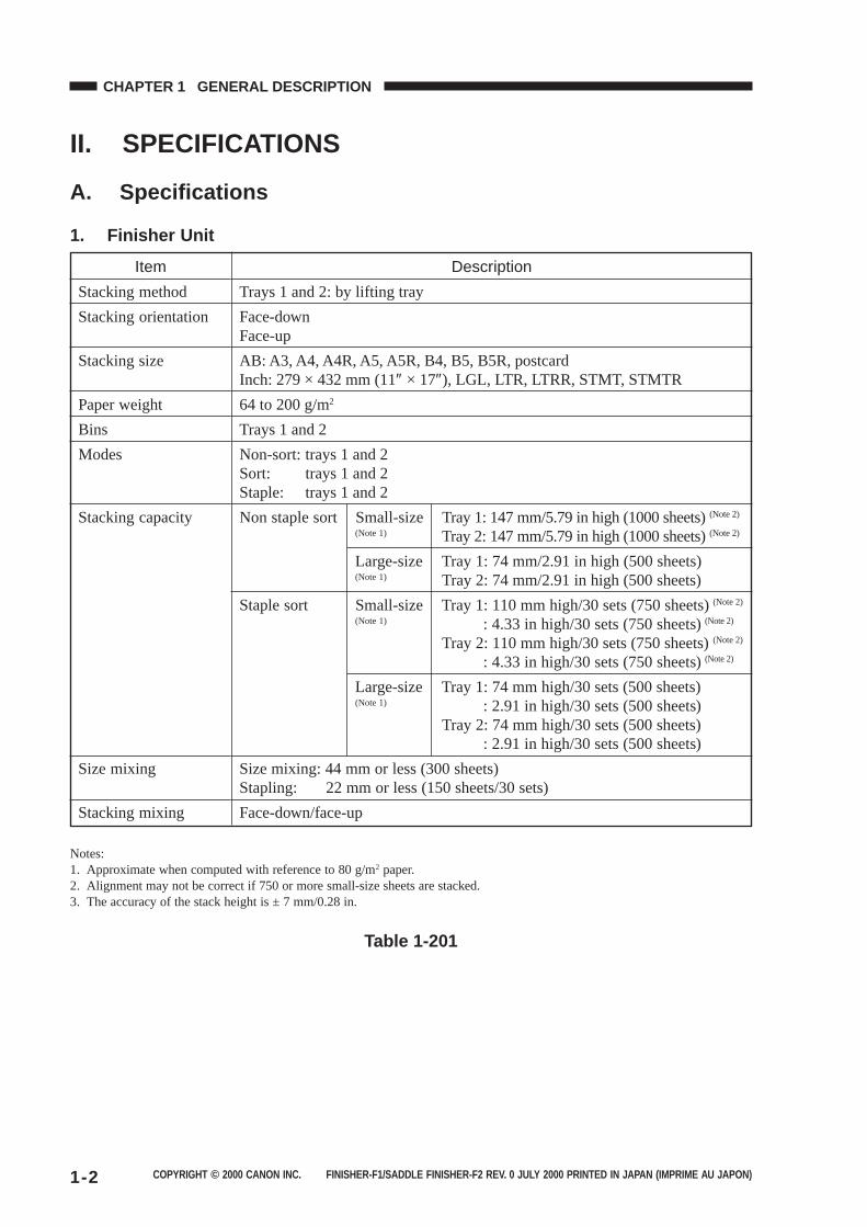
1. Finisher Unit
Item
Stacking method
Stacking orientation
Stacking size
Paper weight
Bins
Modes
Stacking capacity
Size mixing
Stacking mixing
Notes:1. Approximate when computed with reference to 80 g/m2 paper.2. Alignment may not be correct if 750 or more small-size sheets are stacked.3. The accuracy of the stack height is ± 7 mm/0.28 in.
Table 1-201
COPYRIGHT © 2000 CANON INC. FINISHER-F1/SADDLE FINISHER-F2 REV. 0 JULY 2000 PRINTED IN JAPAN (IMPRIME AU JAPON) 1-3
CHAPTER 1 GENERAL DESCRIPTION
Description
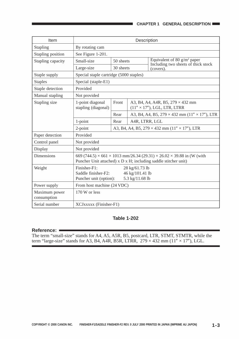
By rotating cam
See Figure 1-201.
Small-size 50 sheets
Large-size 30 sheets
Special staple cartridge (5000 staples)
Special (staple-E1)
Provided
Not provided
1-point diagonal Front A3, B4, A4, A4R, B5, 279 × 432 mmstapling (diagonal) (11″ × 17″), LGL, LTR, LTRR
Rear A3, B4, A4, B5, 279 × 432 mm (11″ × 17″), LTR
1-point Rear A4R, LTRR, LGL
2-point A3, B4, A4, B5, 279 × 432 mm (11″ × 17″), LTR
Provided
Not provided
Not provided
669 (744.5) × 661 × 1013 mm/26.34 (29.31) × 26.02 × 39.88 in (W (withPuncher Unit attached) x D x H; including saddle stitcher unit)
Finisher-F1: 28 kg/61.73 lbSaddle finisher-F2: 46 kg/101.41 lbPuncher unit (option): 5.3 kg/11.68 lb
From host machine (24 VDC)
170 W or less
XCJxxxxx (Finisher-F1)
Table 1-202
Item
Stapling
Stapling position
Stapling capacity
Staple supply
Staples
Staple detection
Manual stapling
Stapling size
Paper detection
Control panel
Display
Dimensions
Weight
Power supply
Maximum powerconsumption
Serial number
Equivalent of 80 g/m2 paperIncluding two sheets of thick stock(covers).
Reference:The term “small-size” stands for A4, A5, A5R, B5, postcard, LTR, STMT, STMTR, while theterm “large-size” stands for A3, B4, A4R, B5R, LTRR, 279 × 432 mm (11″ × 17″), LGL.
COPYRIGHT © 2000 CANON INC. FINISHER-F1/SADDLE FINISHER-F2 REV. 0 JULY 2000 PRINTED IN JAPAN (IMPRIME AU JAPON)1-4
CHAPTER 1 GENERAL DESCRIPTION
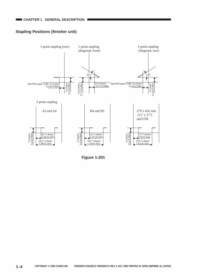
Stapling Positions (finisher unit)
1-point stapling (diagonal; front)
4.4±
2mm
/0.
17±0
.08i
n
2-point stapling
A3 and A4
82.7±4mm/3.26±0.16in
5±2m
m/
0.2±
0.08
in
202.7±4mm/7.98±0.16in
1-point stapling (rear)
5±2m
m/
0.2±
0.08
inSpecified paper width -6±2mm/-0.24±0.08in
4.4±2mm/-0.17±0.08in
30˚
1-point stapling (diagonal; rear)
4±2m
m/
0.16
±0.0
8inSpecified paper width -6±2mm/
-0.24±0.08in
30˚
B4 and B5
5±2m
m/
0.2±
0.08
in 62.7±4mm/2.47±0.16in
182.7±4mm/7.19±0.16in
279 x 432 mm (11'' x 17'') and LTR
5±2m
m/
0.2±
0.08
in 73.7±4mm/2.9±0.16in
193.7±4mm/7.63±0.16in
Figure 1-201
COPYRIGHT © 2000 CANON INC. FINISHER-F1/SADDLE FINISHER-F2 REV. 0 JULY 2000 PRINTED IN JAPAN (IMPRIME AU JAPON) 1-5
CHAPTER 1 GENERAL DESCRIPTION
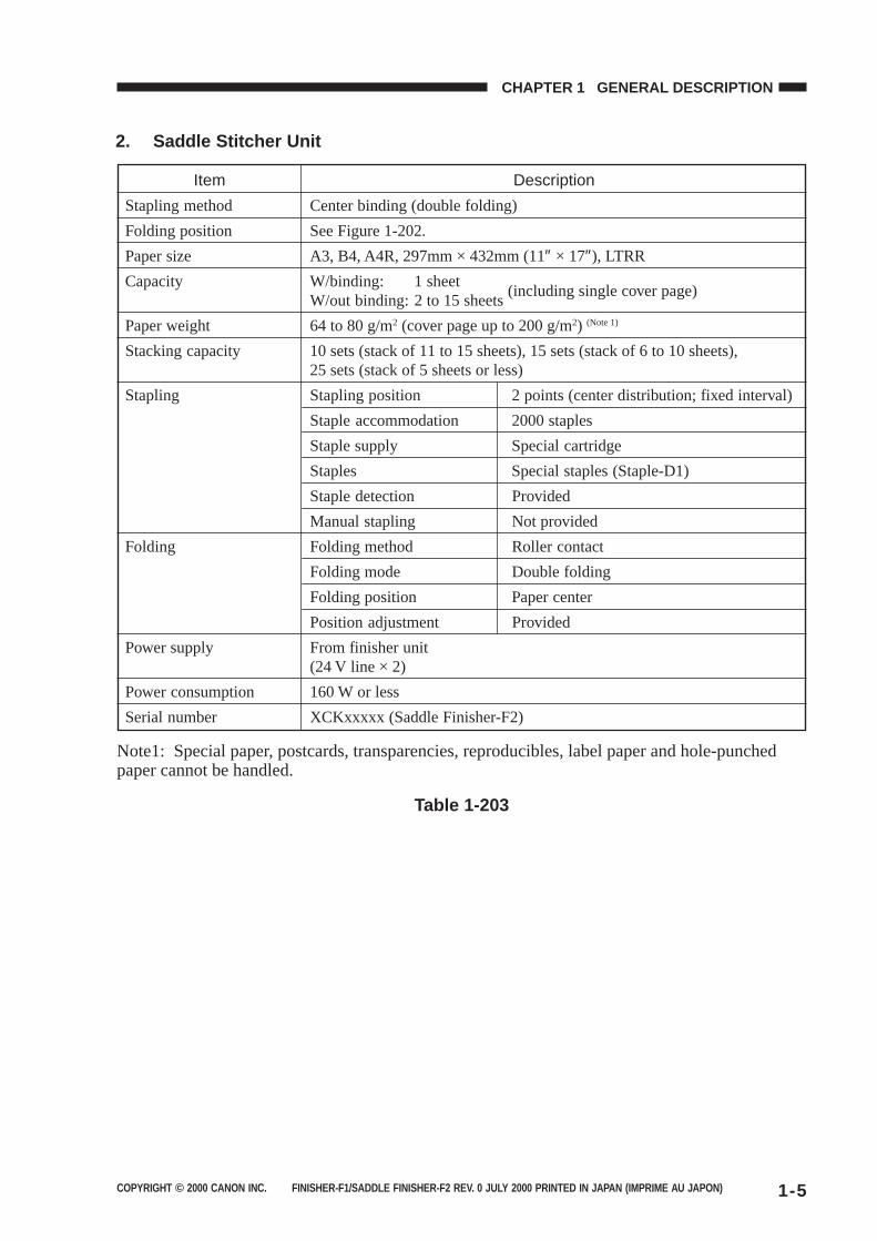
Table 1-203
Description
Center binding (double folding)
See Figure 1-202.
A3, B4, A4R, 297mm × 432mm (11″ × 17″), LTRR
W/binding: 1 sheetW/out binding: 2 to 15 sheets
(including single cover page)
64 to 80 g/m2 (cover page up to 200 g/m2) (Note 1)
10 sets (stack of 11 to 15 sheets), 15 sets (stack of 6 to 10 sheets),25 sets (stack of 5 sheets or less)
Stapling position 2 points (center distribution; fixed interval)
Staple accommodation 2000 staples
Staple supply Special cartridge
Staples Special staples (Staple-D1)
Staple detection Provided
Manual stapling Not provided
Folding method Roller contact
Folding mode Double folding
Folding position Paper center
Position adjustment Provided
From finisher unit(24 V line × 2)
160 W or less
XCKxxxxx (Saddle Finisher-F2)
Item
Stapling method
Folding position
Paper size
Capacity
Paper weight
Stacking capacity
Stapling
Folding
Power supply
Power consumption
Serial number
2. Saddle Stitcher Unit
Note1: Special paper, postcards, transparencies, reproducibles, label paper and hole-punchedpaper cannot be handled.
COPYRIGHT © 2000 CANON INC. FINISHER-F1/SADDLE FINISHER-F2 REV. 0 JULY 2000 PRINTED IN JAPAN (IMPRIME AU JAPON)1-6
CHAPTER 1 GENERAL DESCRIPTION
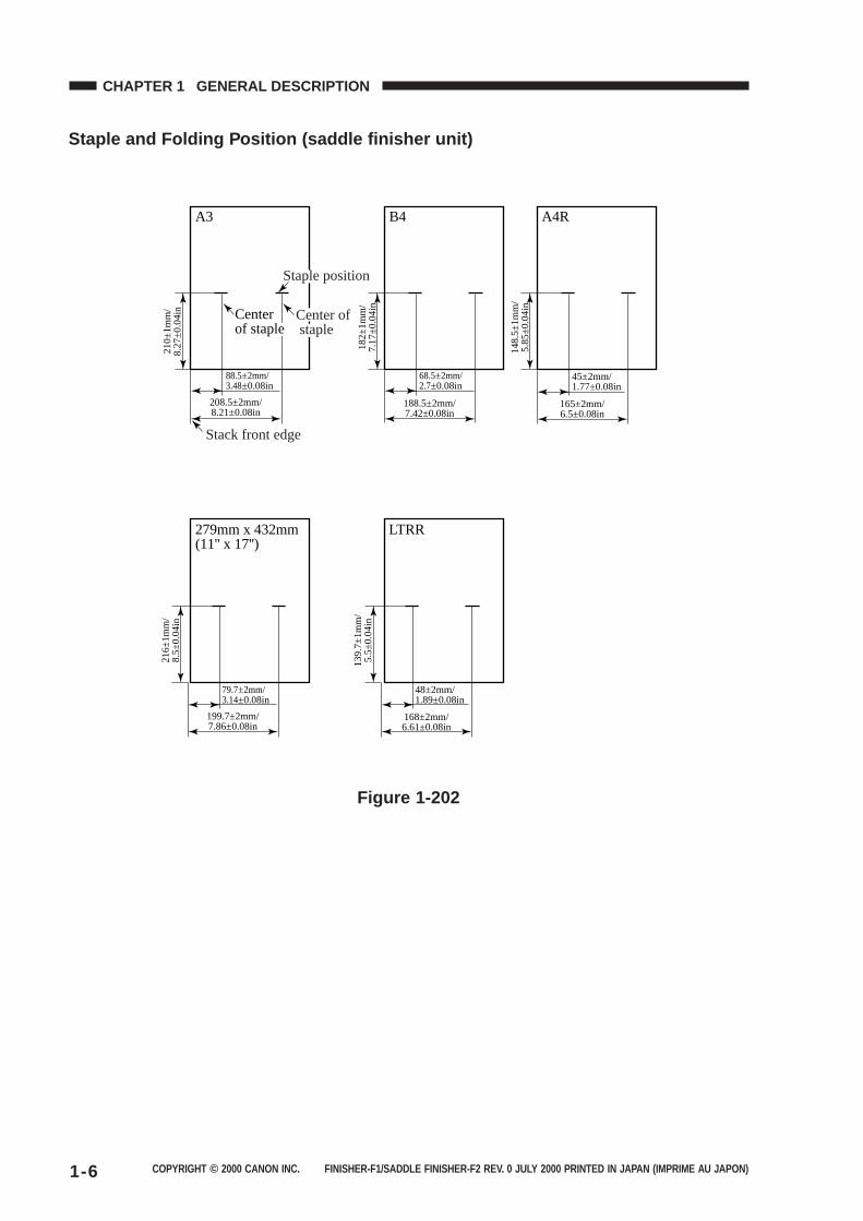
Staple and Folding Position (saddle finisher unit)
208.5±2mm/8.21±0.08in
210±
1mm
/8.
27±0
.04i
n
88.5±2mm/3.48±0.08in
Center of staple
A3
188.5±2mm/7.42±0.08in
182±
1mm
/7.
17±0
.04i
n68.5±2mm/2.7±0.08in
B4
199.7±2mm/7.86±0.08in
216±
1mm
/8.
5±0.
04in
79.7±2mm/3.14±0.08in
279mm x 432mm(11'' x 17'')
168±2mm/6.61±0.08in
139.
7±1m
m/
5.5±
0.04
in
48±2mm/1.89±0.08in
LTRR
165±2mm/6.5±0.08in
148.
5±1m
m/
5.85
±0.0
4in
45±2mm/1.77±0.08in
A4R
Staple position
Center of staple
Stack front edge
Figure 1-202
COPYRIGHT © 2000 CANON INC. FINISHER-F1/SADDLE FINISHER-F2 REV. 0 JULY 2000 PRINTED IN JAPAN (IMPRIME AU JAPON) 1-7
CHAPTER 1 GENERAL DESCRIPTION
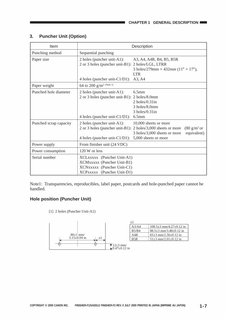
Description
Sequential punching
2 holes (puncher unit-A1): A3, A4, A4R, B4, B5, B5R2 or 3 holes (puncher unit-B1): 2 holes/LGL, LTRR
3 holes/279mm × 432mm (11″ × 17″),LTR
4 holes (puncher unit-C1/D1): A3, A4
64 to 200 g/m2 (Note 1)
2 holes (puncher unit-A1): 6.5mm2 or 3 holes (puncher unit-B1): 2 holes/8.0mm
2 holes/0.31in3 holes/8.0mm3 holes/0.31in
4 holes (puncher unit-C1/D1): 6.5mm
2 holes (puncher unit-A1): 10,000 sheets or more2 or 3 holes (puncher unit-B1): 2 holes/3,000 sheets or more (80 g/m2 or
3 holes/3,000 sheets or more equivalent)4 holes (puncher unit-C1/D1): 5,000 sheets or more
From finisher unit (24 VDC)
120 W or less
XCLxxxxx (Puncher Unit-A1)XCMxxxxx (Puncher Unit-B1)XCNxxxxx (Puncher Unit-C1)XCPxxxxx (Puncher Unit-D1)
Item
Punching method
Paper size
Paper weight
Punched hole diameter
Punched scrap capacity
Power supply
Power consumption
Serial number
3. Puncher Unit (Option)
Note1: Transparencies, reproducibles, label paper, postcards and hole-punched paper cannot behandled.
Hole position (Puncher Unit)
12±3 mm/0.47±0.12 in
80±1 mm/3.15±0.04 in x1
A3/A4 108.5±3 mm/4.27±0.12 inB5/B4 88.5±3 mm/3.48±0.12 inA4R 65±3 mm/2.56±0.12 inB5R 51±3 mm/2.01±0.12 in
x1
[1] 2 holes (Puncher Unit-A1)
COPYRIGHT © 2000 CANON INC. FINISHER-F1/SADDLE FINISHER-F2 REV. 0 JULY 2000 PRINTED IN JAPAN (IMPRIME AU JAPON)1-8
CHAPTER 1 GENERAL DESCRIPTION
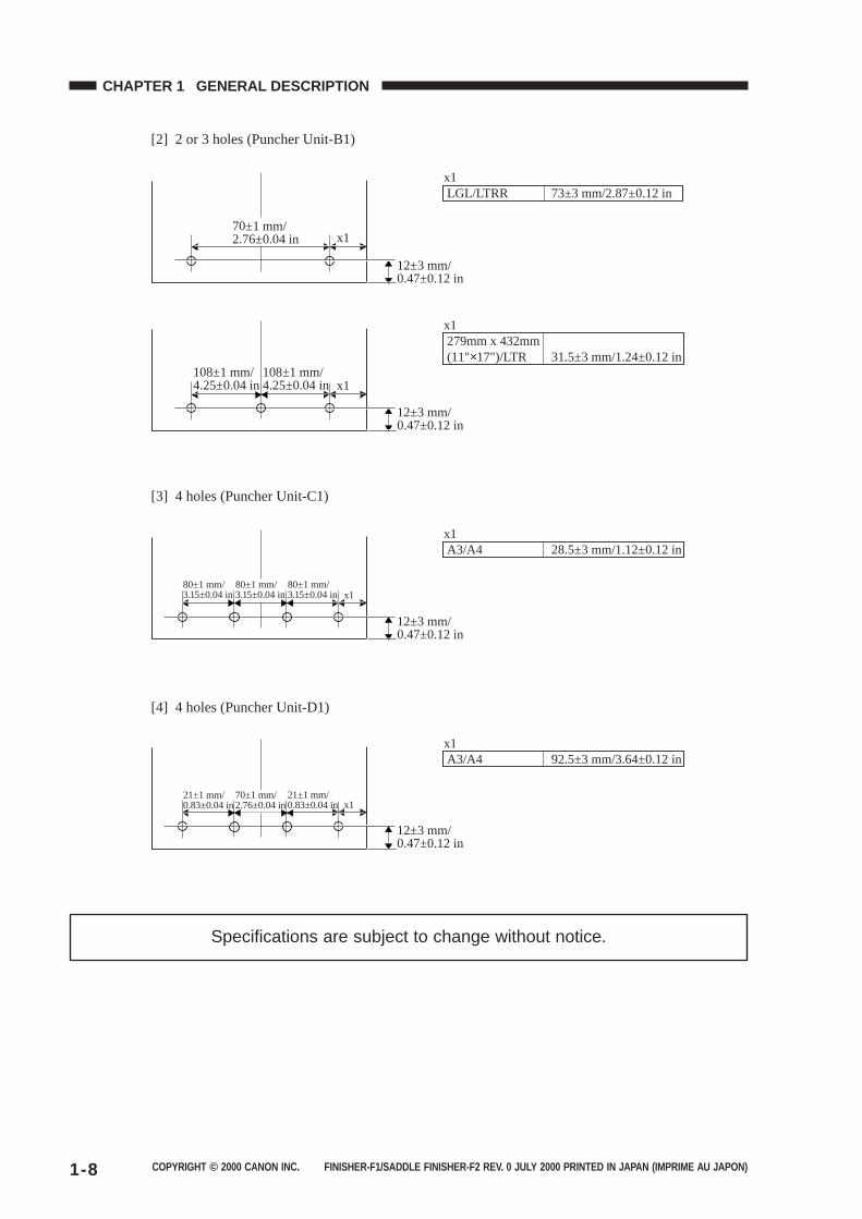
Specifications are subject to change without notice.
12±3 mm/0.47±0.12 in
70±1 mm/2.76±0.04 in x1
LGL/LTRR 73±3 mm/2.87±0.12 inx1
12±3 mm/0.47±0.12 in
108±1 mm/4.25±0.04 in x1
279mm x 432mm(11"×17")/LTR 31.5±3 mm/1.24±0.12 in
x1
108±1 mm/4.25±0.04 in
80±1 mm/3.15±0.04 in
12±3 mm/0.47±0.12 in
80±1 mm/3.15±0.04 in x1
A3/A4 28.5±3 mm/1.12±0.12 inx1
80±1 mm/3.15±0.04 in
21±1 mm/0.83±0.04 in
12±3 mm/0.47±0.12 in
70±1 mm/2.76±0.04 in x1
A3/A4 92.5±3 mm/3.64±0.12 inx1
21±1 mm/0.83±0.04 in
[2] 2 or 3 holes (Puncher Unit-B1)
[3] 4 holes (Puncher Unit-C1)
[4] 4 holes (Puncher Unit-D1)
COPYRIGHT © 2000 CANON INC. FINISHER-F1/SADDLE FINISHER-F2 REV. 0 JULY 2000 PRINTED IN JAPAN (IMPRIME AU JAPON) 1-9
CHAPTER 1 GENERAL DESCRIPTION
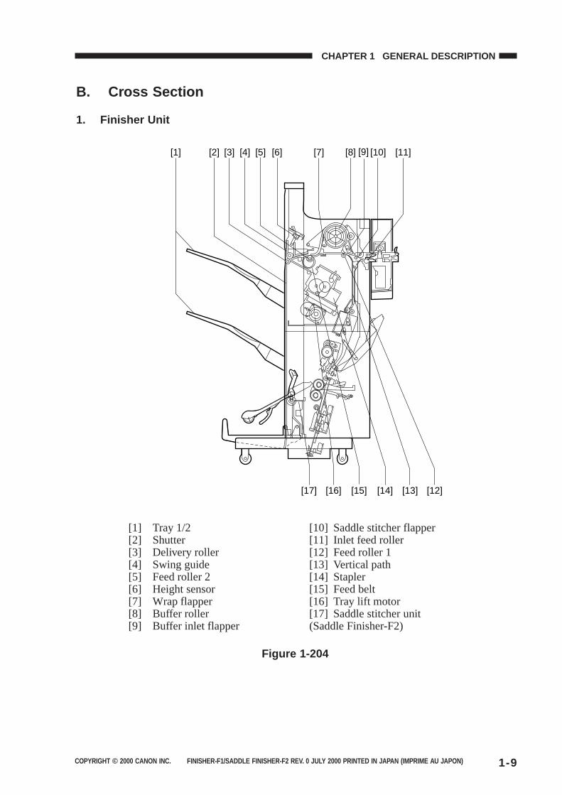
B. Cross Section
1. Finisher Unit
[17] [16] [15] [14] [13] [12]
[1] [2] [3] [4] [5] [6] [8][7] [10][9] [11]
[1] Tray 1/2[2] Shutter[3] Delivery roller[4] Swing guide[5] Feed roller 2[6] Height sensor[7] Wrap flapper[8] Buffer roller[9] Buffer inlet flapper
[10] Saddle stitcher flapper[11] Inlet feed roller[12] Feed roller 1[13] Vertical path[14] Stapler[15] Feed belt[16] Tray lift motor[17] Saddle stitcher unit(Saddle Finisher-F2)
Figure 1-204
COPYRIGHT © 2000 CANON INC. FINISHER-F1/SADDLE FINISHER-F2 REV. 0 JULY 2000 PRINTED IN JAPAN (IMPRIME AU JAPON)1-10
CHAPTER 1 GENERAL DESCRIPTION
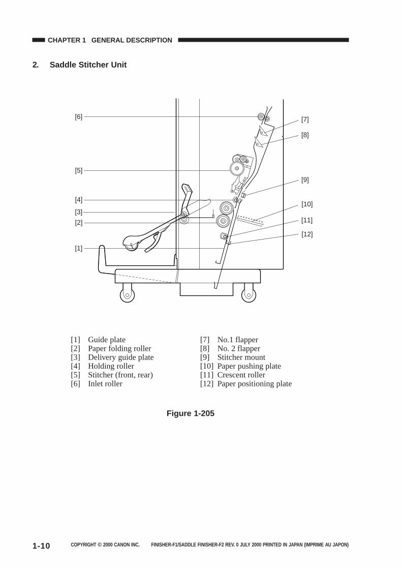
2. Saddle Stitcher Unit
[5]
[6]
[4]
[3]
[2]
[1]
[12]
[11]
[10]
[9]
[8]
[7]
[1] Guide plate[2] Paper folding roller[3] Delivery guide plate[4] Holding roller[5] Stitcher (front, rear)[6] Inlet roller
[7] No.1 flapper[8] No. 2 flapper[9] Stitcher mount[10] Paper pushing plate[11] Crescent roller[12] Paper positioning plate
Figure 1-205
COPYRIGHT © 2000 CANON INC. FINISHER-F1/SADDLE FINISHER-F2 REV. 0 JULY 2000 PRINTED IN JAPAN (IMPRIME AU JAPON) 1-11
CHAPTER 1 GENERAL DESCRIPTION
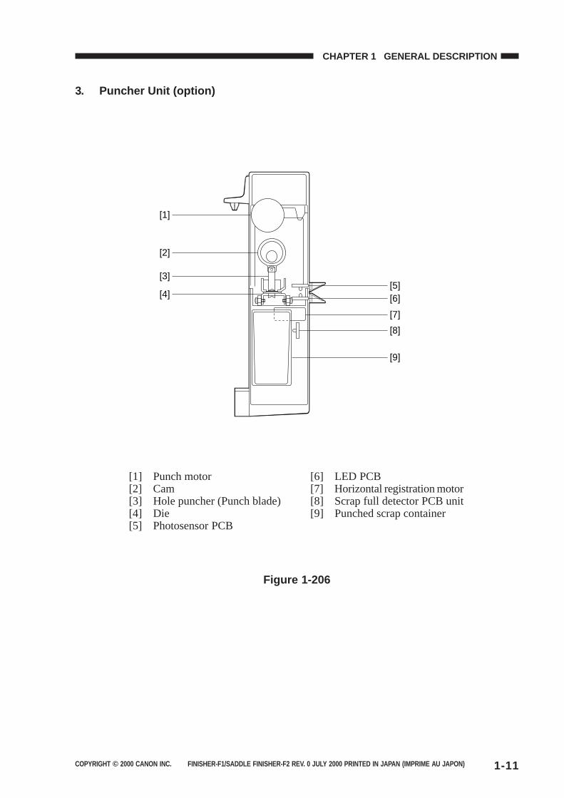
3. Puncher Unit (option)
[1] Punch motor[2] Cam[3] Hole puncher (Punch blade)[4] Die[5] Photosensor PCB
[6] LED PCB[7] Horizontal registration motor[8] Scrap full detector PCB unit[9] Punched scrap container
Figure 1-206
[1]
[2]
[3]
[4][5][6]
[7]
[8]
[9]
COPYRIGHT © 2000 CANON INC. FINISHER-F1/SADDLE FINISHER-F2 REV. 0 JULY 2000 PRINTED IN JAPAN (IMPRIME AU JAPON)1-12
CHAPTER 1 GENERAL DESCRIPTION
III. Using the Machine
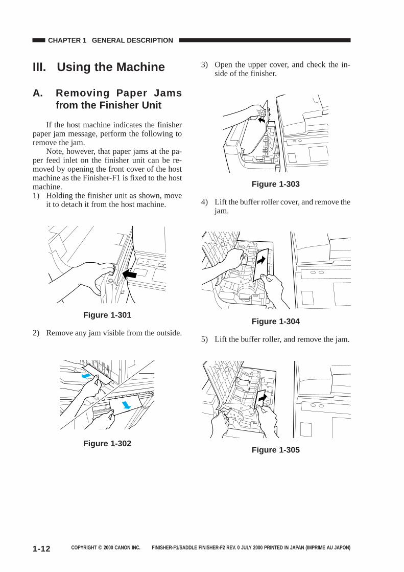
A. Removing Paper Jamsfrom the Finisher Unit
If the host machine indicates the finisherpaper jam message, perform the following toremove the jam.
Note, however, that paper jams at the pa-per feed inlet on the finisher unit can be re-moved by opening the front cover of the hostmachine as the Finisher-F1 is fixed to the hostmachine.1) Holding the finisher unit as shown, move
it to detach it from the host machine.
Figure 1-301
2) Remove any jam visible from the outside.
Figure 1-302
3) Open the upper cover, and check the in-side of the finisher.
Figure 1-303
4) Lift the buffer roller cover, and remove thejam.
Figure 1-304
5) Lift the buffer roller, and remove the jam.
Figure 1-305
COPYRIGHT © 2000 CANON INC. FINISHER-F1/SADDLE FINISHER-F2 REV. 0 JULY 2000 PRINTED IN JAPAN (IMPRIME AU JAPON) 1-13
CHAPTER 1 GENERAL DESCRIPTION
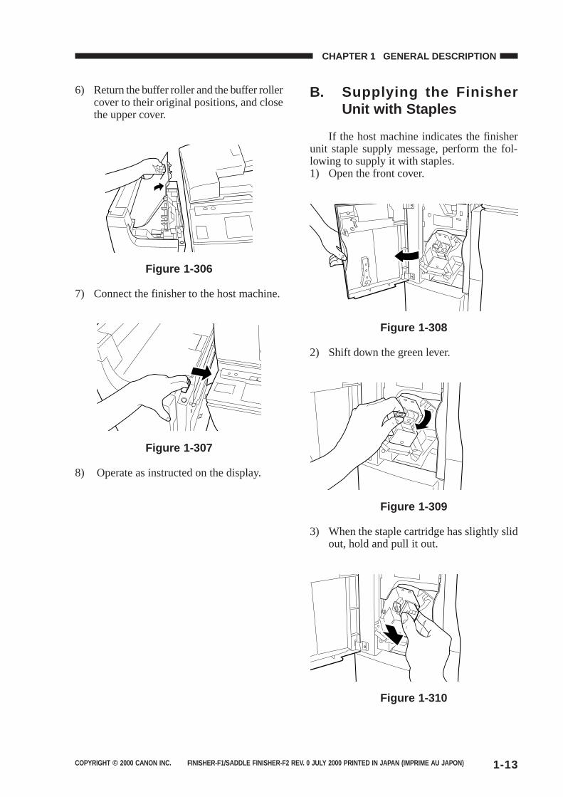
6) Return the buffer roller and the buffer rollercover to their original positions, and closethe upper cover.
Figure 1-306
7) Connect the finisher to the host machine.
Figure 1-307
8) Operate as instructed on the display.
B. Supplying the FinisherUnit with Staples
If the host machine indicates the finisherunit staple supply message, perform the fol-lowing to supply it with staples.1) Open the front cover.
Figure 1-308
2) Shift down the green lever.
Figure 1-309
3) When the staple cartridge has slightly slidout, hold and pull it out.
Figure 1-310
COPYRIGHT © 2000 CANON INC. FINISHER-F1/SADDLE FINISHER-F2 REV. 0 JULY 2000 PRINTED IN JAPAN (IMPRIME AU JAPON)1-14
CHAPTER 1 GENERAL DESCRIPTION
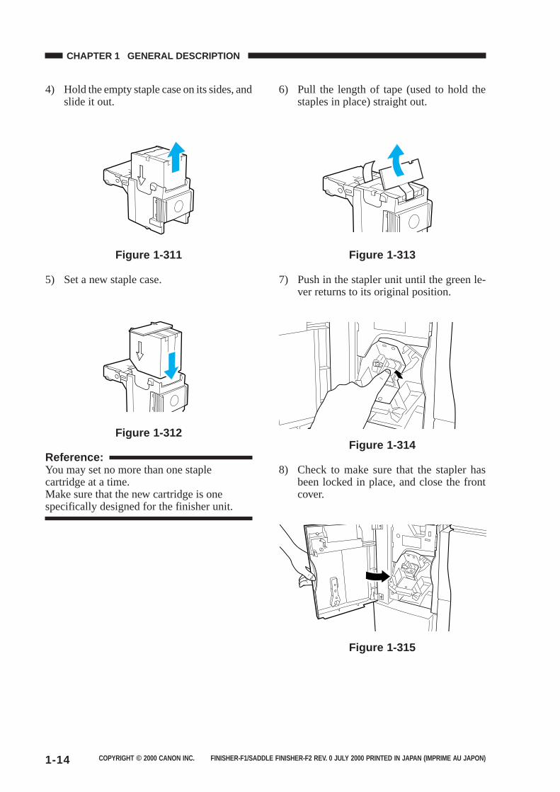
4) Hold the empty staple case on its sides, andslide it out.
Figure 1-311
5) Set a new staple case.
Figure 1-312
Reference:You may set no more than one staplecartridge at a time.Make sure that the new cartridge is onespecifically designed for the finisher unit.
6) Pull the length of tape (used to hold thestaples in place) straight out.
Figure 1-313
7) Push in the stapler unit until the green le-ver returns to its original position.
Figure 1-314
8) Check to make sure that the stapler hasbeen locked in place, and close the frontcover.
Figure 1-315
COPYRIGHT © 2000 CANON INC. FINISHER-F1/SADDLE FINISHER-F2 REV. 0 JULY 2000 PRINTED IN JAPAN (IMPRIME AU JAPON) 1-15
CHAPTER 1 GENERAL DESCRIPTION
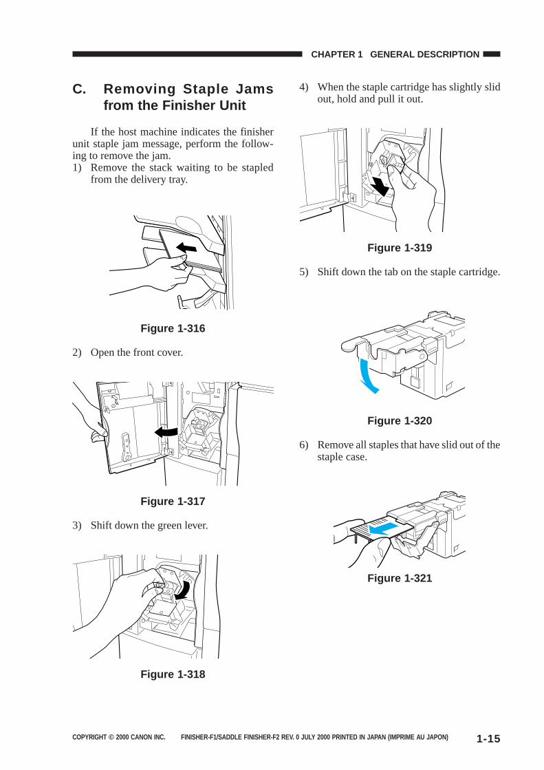
C. Removing Staple Jamsfrom the Finisher Unit
If the host machine indicates the finisherunit staple jam message, perform the follow-ing to remove the jam.1) Remove the stack waiting to be stapled
from the delivery tray.
Figure 1-316
2) Open the front cover.
Figure 1-317
3) Shift down the green lever.
Figure 1-318
4) When the staple cartridge has slightly slidout, hold and pull it out.
Figure 1-319
5) Shift down the tab on the staple cartridge.
Figure 1-320
6) Remove all staples that have slid out of thestaple case.
Figure 1-321
COPYRIGHT © 2000 CANON INC. FINISHER-F1/SADDLE FINISHER-F2 REV. 0 JULY 2000 PRINTED IN JAPAN (IMPRIME AU JAPON)1-16
CHAPTER 1 GENERAL DESCRIPTION
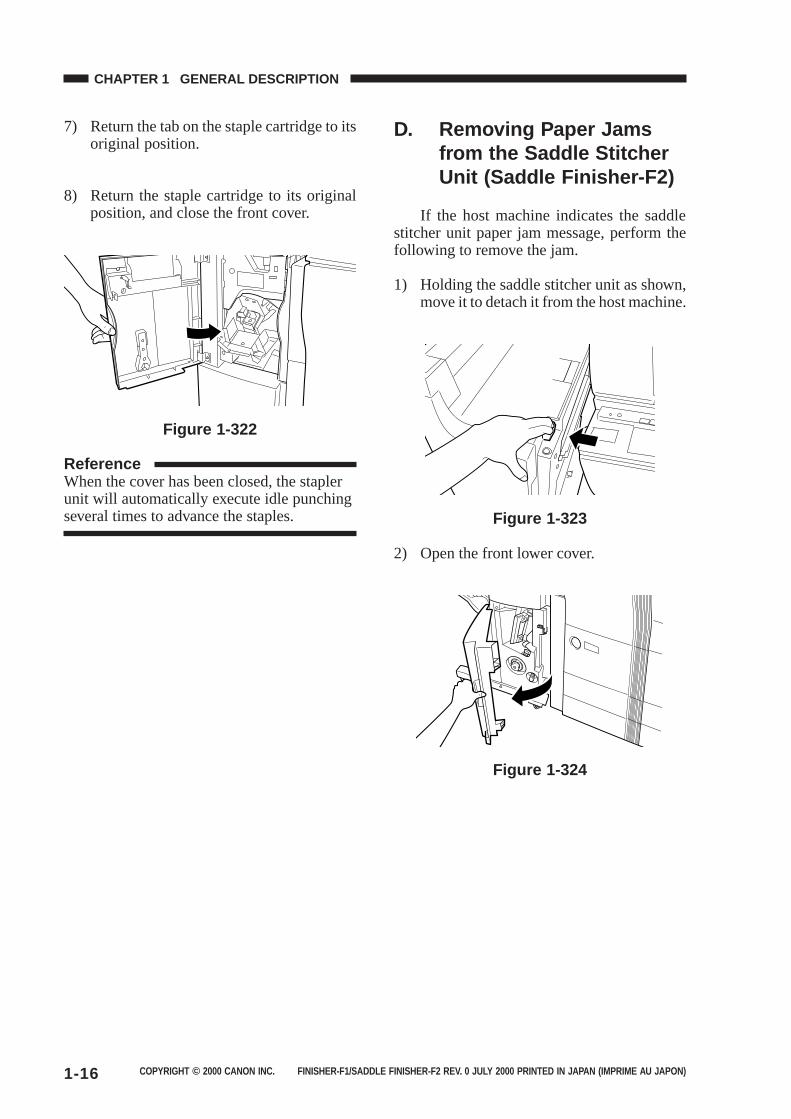
7) Return the tab on the staple cartridge to itsoriginal position.
8) Return the staple cartridge to its originalposition, and close the front cover.
Figure 1-322
ReferenceWhen the cover has been closed, the staplerunit will automatically execute idle punchingseveral times to advance the staples.
D. Removing Paper Jamsfrom the Saddle StitcherUnit (Saddle Finisher-F2)
If the host machine indicates the saddlestitcher unit paper jam message, perform thefollowing to remove the jam.
1) Holding the saddle stitcher unit as shown,move it to detach it from the host machine.
Figure 1-323
2) Open the front lower cover.
Figure 1-324
COPYRIGHT © 2000 CANON INC. FINISHER-F1/SADDLE FINISHER-F2 REV. 0 JULY 2000 PRINTED IN JAPAN (IMPRIME AU JAPON) 1-17
CHAPTER 1 GENERAL DESCRIPTION
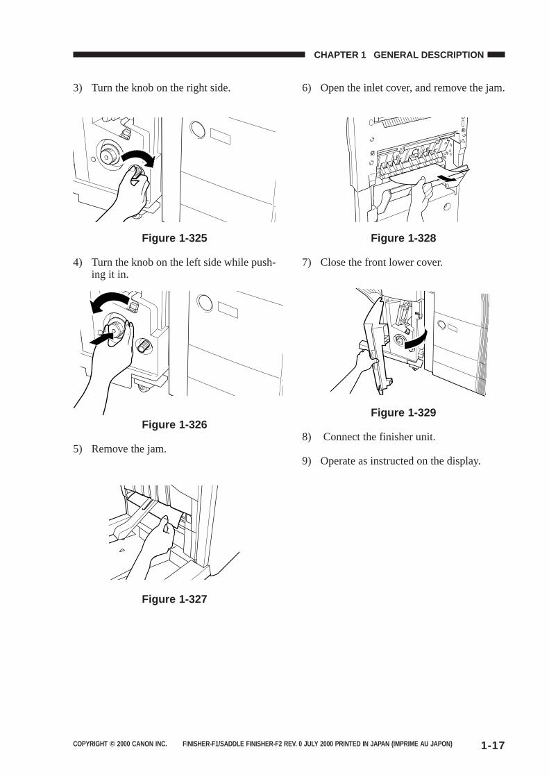
3) Turn the knob on the right side.
Figure 1-325
4) Turn the knob on the left side while push-ing it in.
Figure 1-326
5) Remove the jam.
Figure 1-327
6) Open the inlet cover, and remove the jam.
Figure 1-328
7) Close the front lower cover.
Figure 1-329
8) Connect the finisher unit.
9) Operate as instructed on the display.
COPYRIGHT © 2000 CANON INC. FINISHER-F1/SADDLE FINISHER-F2 REV. 0 JULY 2000 PRINTED IN JAPAN (IMPRIME AU JAPON)1-18
CHAPTER 1 GENERAL DESCRIPTION
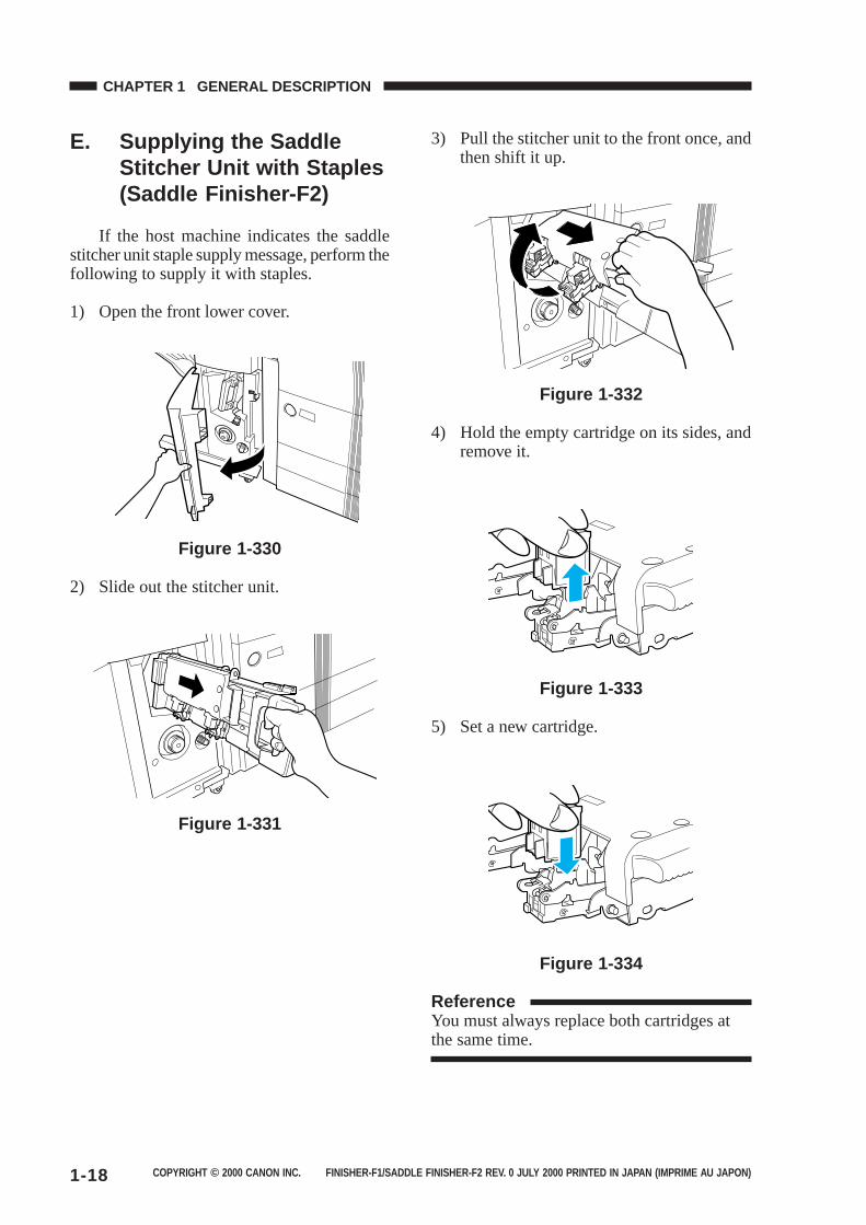
E. Supplying the SaddleStitcher Unit with Staples(Saddle Finisher-F2)
If the host machine indicates the saddlestitcher unit staple supply message, perform thefollowing to supply it with staples.
1) Open the front lower cover.
Figure 1-330
2) Slide out the stitcher unit.
Figure 1-331
3) Pull the stitcher unit to the front once, andthen shift it up.
Figure 1-332
4) Hold the empty cartridge on its sides, andremove it.
Figure 1-333
5) Set a new cartridge.
Figure 1-334
ReferenceYou must always replace both cartridges atthe same time.
COPYRIGHT © 2000 CANON INC. FINISHER-F1/SADDLE FINISHER-F2 REV. 0 JULY 2000 PRINTED IN JAPAN (IMPRIME AU JAPON) 1-19
CHAPTER 1 GENERAL DESCRIPTION
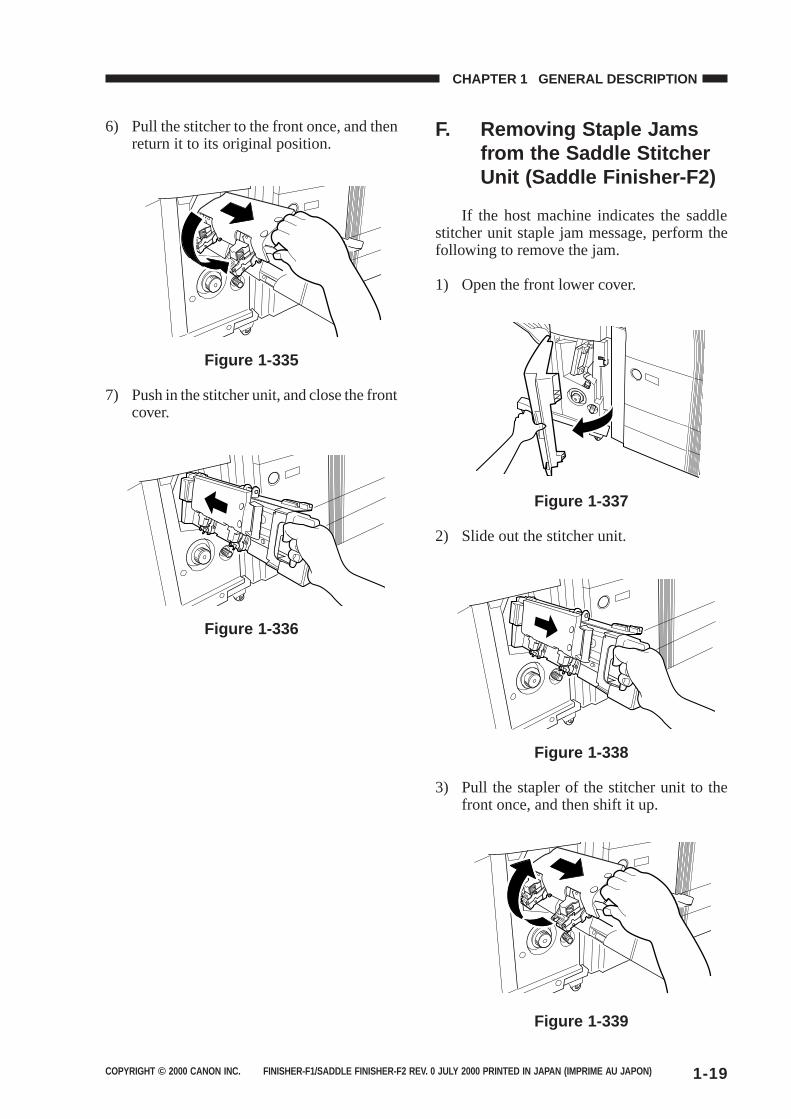
6) Pull the stitcher to the front once, and thenreturn it to its original position.
Figure 1-335
7) Push in the stitcher unit, and close the frontcover.
Figure 1-336
F. Removing Staple Jamsfrom the Saddle StitcherUnit (Saddle Finisher-F2)
If the host machine indicates the saddlestitcher unit staple jam message, perform thefollowing to remove the jam.
1) Open the front lower cover.
Figure 1-337
2) Slide out the stitcher unit.
Figure 1-338
3) Pull the stapler of the stitcher unit to thefront once, and then shift it up.
Figure 1-339
COPYRIGHT © 2000 CANON INC. FINISHER-F1/SADDLE FINISHER-F2 REV. 0 JULY 2000 PRINTED IN JAPAN (IMPRIME AU JAPON)1-20
CHAPTER 1 GENERAL DESCRIPTION
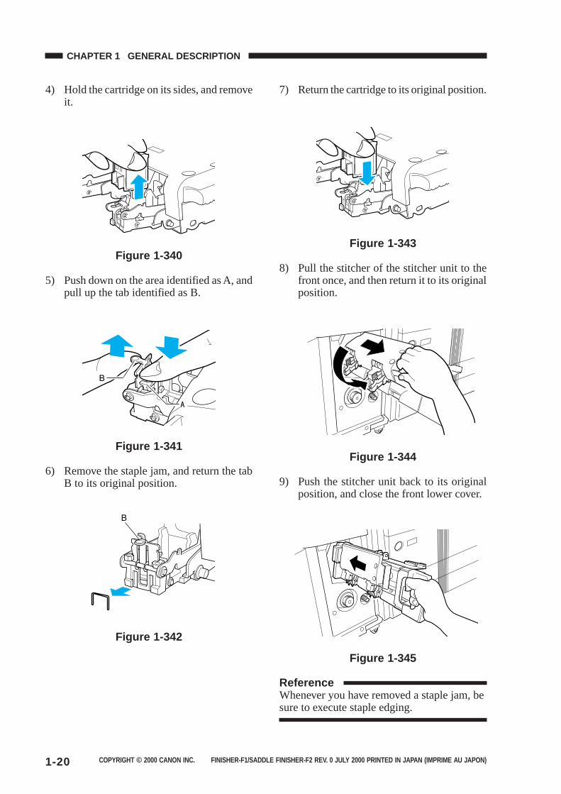
4) Hold the cartridge on its sides, and removeit.
Figure 1-340
5) Push down on the area identified as A, andpull up the tab identified as B.
Figure 1-341
6) Remove the staple jam, and return the tabB to its original position.
Figure 1-342
7) Return the cartridge to its original position.
Figure 1-343
8) Pull the stitcher of the stitcher unit to thefront once, and then return it to its originalposition.
Figure 1-344
9) Push the stitcher unit back to its originalposition, and close the front lower cover.
Figure 1-345
ReferenceWhenever you have removed a staple jam, besure to execute staple edging.
COPYRIGHT © 2000 CANON INC. FINISHER-F1/SADDLE FINISHER-F2 REV. 0 JULY 2000 PRINTED IN JAPAN (IMPRIME AU JAPON) 1-21
CHAPTER 1 GENERAL DESCRIPTION
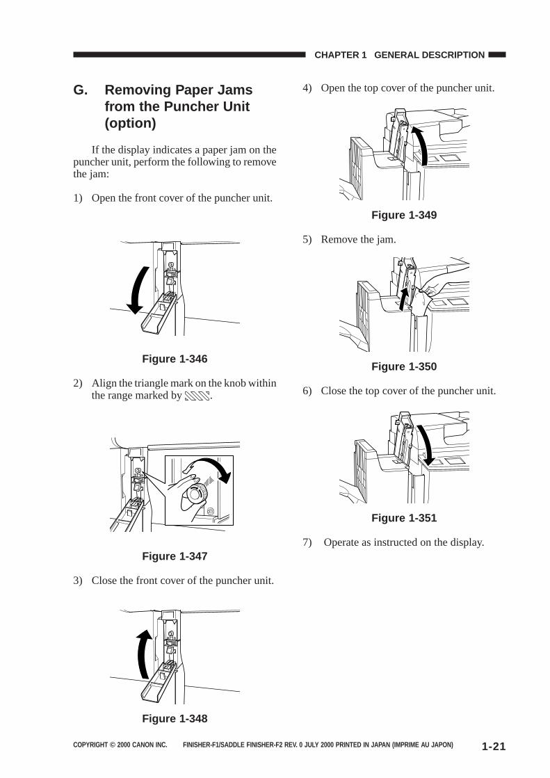
G. Removing Paper Jamsfrom the Puncher Unit(option)
If the display indicates a paper jam on thepuncher unit, perform the following to removethe jam:
1) Open the front cover of the puncher unit.
Figure 1-346
2) Align the triangle mark on the knob withinthe range marked by .
Figure 1-347
3) Close the front cover of the puncher unit.
Figure 1-348
4) Open the top cover of the puncher unit.
Figure 1-349
5) Remove the jam.
Figure 1-350
6) Close the top cover of the puncher unit.
Figure 1-351
7) Operate as instructed on the display.
COPYRIGHT © 2000 CANON INC. FINISHER-F1/SADDLE FINISHER-F2 REV. 0 JULY 2000 PRINTED IN JAPAN (IMPRIME AU JAPON)1-22
CHAPTER 1 GENERAL DESCRIPTION
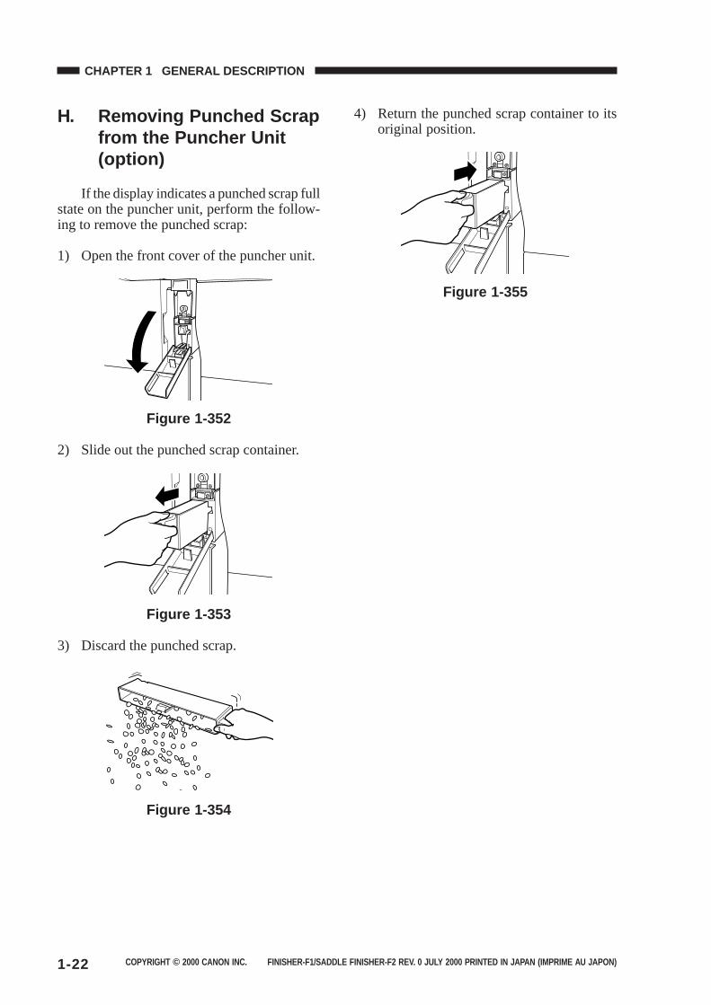
H. Removing Punched Scrapfrom the Puncher Unit(option)
If the display indicates a punched scrap fullstate on the puncher unit, perform the follow-ing to remove the punched scrap:
1) Open the front cover of the puncher unit.
Figure 1-352
2) Slide out the punched scrap container.
Figure 1-353
3) Discard the punched scrap.
Figure 1-354
4) Return the punched scrap container to itsoriginal position.
Figure 1-355
COPYRIGHT © 2000 CANON INC. FINISHER-F1/SADDLE FINISHER-F2 REV. 0 JULY 2000 PRINTED IN JAPAN (IMPRIME AU JAPON) 1-23
CHAPTER 1 GENERAL DESCRIPTION
IV. MAINTENANCE BY THE USER
A. Maintenance by the User
As of June 2000
Timing
When the appropriate indication is made onthe host machine’s display.
Item
Replacing the staple cartridge (finisher unit)
Replacing the staple cartridge (saddle stitcherunit)
Caution:The finisher unit and the saddle stitcher unit use different cartridge types. Be sure that theappropriate type is used for each.
Table 1-401
No.
1
2

COPYRIGHT © 2000 CANON INC. FINISHER-F1/SADDLE FINISHER-F2 REV. 0 JULY 2000 PRINTED IN JAPAN (IMPRIME AU JAPON)
CHAPTER 2
FINISHER UNIT BASIC OPERATION
I. BASIC OPERATION...................2-1A. Outline ..................................2-1B. Outline of Electrical
Circuitry ................................2-2C. Inputs to and Outputs from the
Finisher Controller PCB .......2-4II. FEED/DRIVE SYSTEM ........... 2-10
A. Outline ............................... 2-10B. Type of Delivery Paths....... 2-15C. Feeding and Delivering ..... 2-18
D. Job Offset .......................... 2-21E. Staple Operation ............... 2-24F. Stapler Unit ........................ 2-32G. Tray Operation ................... 2-38H. Detecting the Height of
Stack on the Tray ............... 2-40I. Shutter Operation .............. 2-42J. Buffer Path Operation ........ 2-46K. Detecting Jams .................. 2-51
III. POWER SUPPLY SYSTEM .... 2-56
1. This chapter discusses the purpose and role of each of the finisher’s functions, and the prin-ciples of operation used for the finisher mechanical and electrical systems. It also explains thetiming at which these systems are operated.The symbol in drawings indicates transmissionof mechanical drive, and signals marked by together with the signal name indicates theflow of electrical signals.
2. In descriptions of digital circuits on the finisher, “1” indicates a high signal voltage level, while“0” indicates a low signal voltage level. Voltage values differ according to circuit.
A microprocessor is used on the finisher. A description of microprocessor operation is omittedin this chapter as it is practically impossible to check internal operation of the microprocessor.
Descriptions in this chapter also assume that PCBs will not be repaired at user sites. For thisreason, descriptions of circuits on PCBs is limited to block diagrams. Two types of block dia-grams are provided for separate functions: diagrams indicating details from sensors up to inputsections of major PCBs, and diagrams indicating details from the output sections of majorPCBs up the loads.

COPYRIGHT © 2000 CANON INC. FINISHER-F1/SADDLE FINISHER-F2 REV. 0 JULY 2000 PRINTED IN JAPAN (IMPRIME AU JAPON) 2-1
CHAPTER 2 FINISHER UNIT BASIC OPERATION
I. BASIC OPERATION
A. Outline
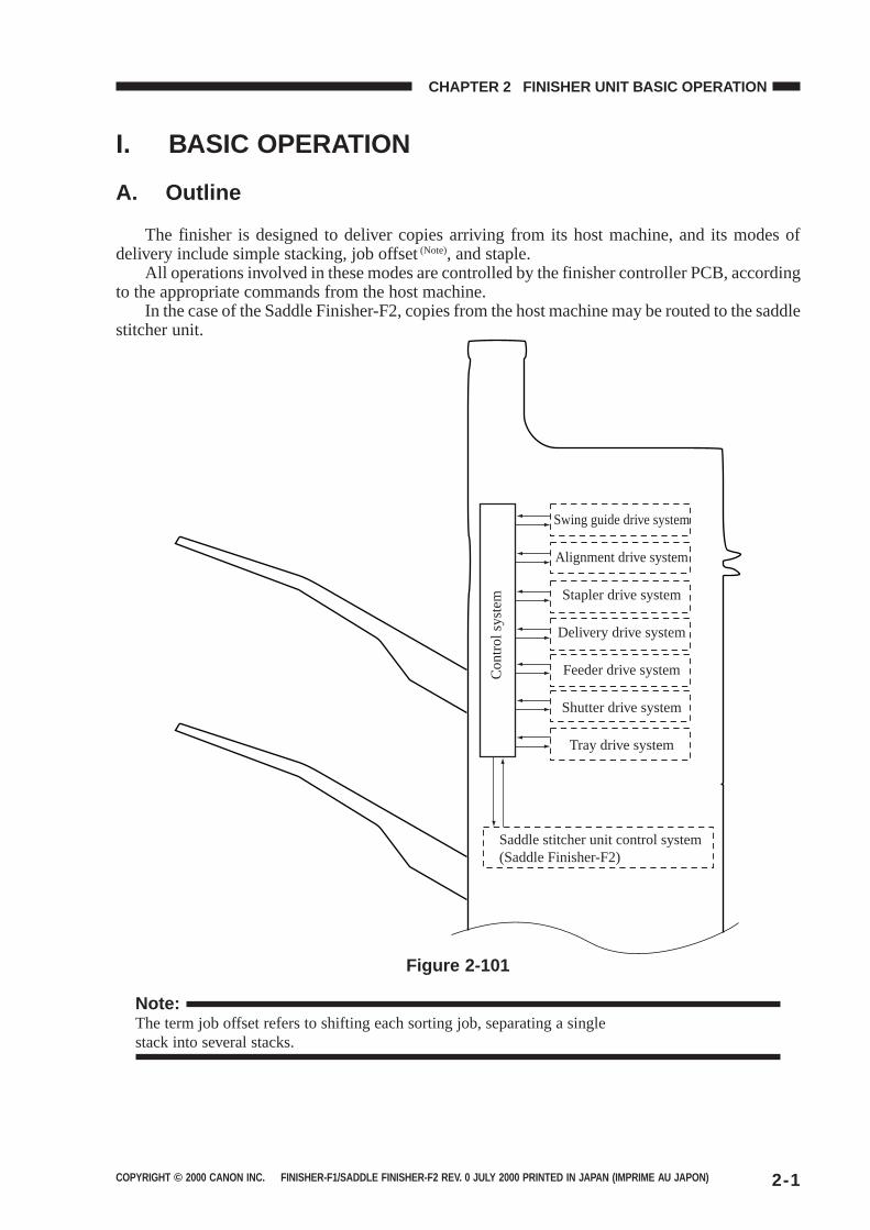
The finisher is designed to deliver copies arriving from its host machine, and its modes ofdelivery include simple stacking, job offset (Note), and staple.
All operations involved in these modes are controlled by the finisher controller PCB, accordingto the appropriate commands from the host machine.
In the case of the Saddle Finisher-F2, copies from the host machine may be routed to the saddlestitcher unit.
Swing guide drive system
Alignment drive system
Stapler drive system
Delivery drive system
Feeder drive system
Shutter drive system
Tray drive system
Saddle stitcher unit control system(Saddle Finisher-F2)
Con
trol
sys
tem
Figure 2-101
Note:The term job offset refers to shifting each sorting job, separating a singlestack into several stacks.
COPYRIGHT © 2000 CANON INC. FINISHER-F1/SADDLE FINISHER-F2 REV. 0 JULY 2000 PRINTED IN JAPAN (IMPRIME AU JAPON)2-2
CHAPTER 2 FINISHER UNIT BASIC OPERATION
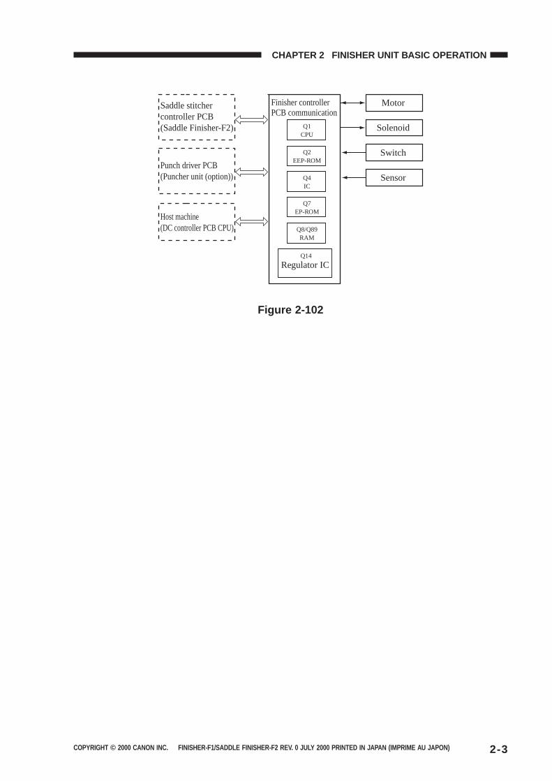
B. Outline of Electrical Circuitry
The finisher’s sequence of operation is controlled by the finisher controller PCB. The finishercontroller PCB is a 16-bit microprocessor (CPU), and is used for communication with the hostmachine (serial) in addition to controlling the finisher’s sequence of operations.
The finisher controller PCB responds to the various commands coming from the host machinethrough a serial communications line to drive solenoids, motors, and other loads. In addition, itcommunicates the finisher’s various states (information on sensors and switches) to the host ma-chine through a serial communications circuit.
In the case of the Saddle Finisher-F2, the finisher controller PCB not only communicates withthe saddle stitcher controller PCB but also communicates the saddle stitcher unit’s various states(information on sensors and switches) to the host machine.
The ICs used on the finisher controller PCB are designed for the following:● Q1 (CPU)
Controls sequence of operations.● Q2 (EP-ROM)
Backs up adjustment values.● Q7
Contains sequence programs.● Q8/Q89 (RAM)
Backs up initial setting data.● Q4 (communications IC)
Communicates with the host machine and the saddle stitcher unit.● Q14 (regulator IC)
Generates 5V.
Figure 2-102 shows the flow of signals between the finisher and the options controller.
COPYRIGHT © 2000 CANON INC. FINISHER-F1/SADDLE FINISHER-F2 REV. 0 JULY 2000 PRINTED IN JAPAN (IMPRIME AU JAPON) 2-3
CHAPTER 2 FINISHER UNIT BASIC OPERATION
Q1CPU
Q2EEP-ROM
Q4IC
Q7EP-ROM
Q8/Q89RAM
Q14
Saddle stitcher controller PCB(Saddle Finisher-F2)
Punch driver PCB(Puncher unit (option))
Host machine(DC controller PCB CPU)
Finisher controller PCB communication
Regulator IC
Motor
Solenoid
Switch
Sensor
Figure 2-102
COPYRIGHT © 2000 CANON INC. FINISHER-F1/SADDLE FINISHER-F2 REV. 0 JULY 2000 PRINTED IN JAPAN (IMPRIME AU JAPON)2-4
CHAPTER 2 FINISHER UNIT BASIC OPERATION
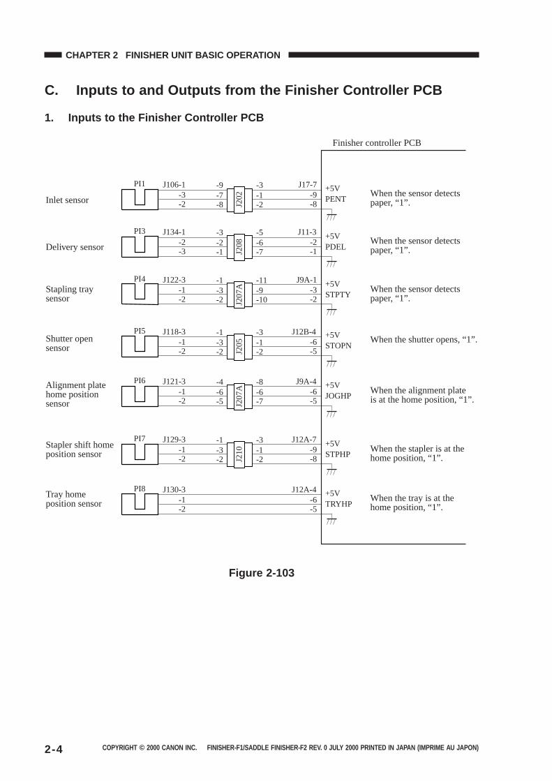
C. Inputs to and Outputs from the Finisher Controller PCB
1. Inputs to the Finisher Controller PCB
PI8
J210
J130-3-1-2
PI7 J129-3-1-2
J12A-7-9-8
J12A-4-6-5
-3-1
-2-1-3
-2
J207
A
PI6 J121-3-1-2
J9A-4-6-5
-6-4
-5-6-8
-7
J205
PI5 J118-3-1-2
J12B-4-6-5
-3-1
-2-1-3
-2
J207
A
PI4 J122-3-1-2
J9A-1-3-2
-3-1
-2-9-11
-10
J208
PI3 J134-1-2-3
J11-3-2-1
-2-3
-1-6-5
-7
J202
PI1 J106-1-3-2
J17-7 +5VPENT
+5VPDEL
+5VSTOPN
+5VJOGHP
+5VSTPHP
+5VTRYHP
+5VSTPTY
-9-8
-7-9
-8-1-3
-2Inlet sensor
Delivery sensor
Stapling tray sensor
Shutter open sensor
Alignment platehome positionsensor
Stapler shift home position sensor
Tray home position sensor
Finisher controller PCB
When the sensor detects paper, “1”.
When the sensor detects paper, “1”.
When the sensor detects paper, “1”.
When the shutter opens, “1”.
When the alignment plateis at the home position, “1”.
When the stapler is at the home position, “1”.
When the tray is at the home position, “1”.
Figure 2-103
COPYRIGHT © 2000 CANON INC. FINISHER-F1/SADDLE FINISHER-F2 REV. 0 JULY 2000 PRINTED IN JAPAN (IMPRIME AU JAPON) 2-5
CHAPTER 2 FINISHER UNIT BASIC OPERATION
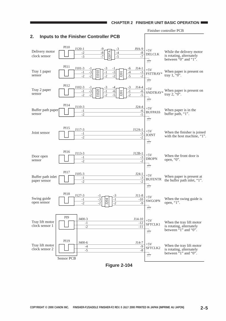
2. Inputs to the Finisher Controller PCB
PI10 J120-1-2-3
-9-8-7
-3-4-5
J9A-9 +5VDELCLK-8
-7J207
A
PI11 J101-3-1-2
-1-3-2
-3-1-2
J14-1 +5VFSTTRAY*-3
-2J101
0
PI12 J102-3-1-2
-1-3-2
-3-1-2
J14-4 +5VSNDTRAY*-6
-5J102
0
-1-3-2
-6-4-5J2
01
-4-6-5
-3-1-2J2
01
PI14 J110-3-1-2
J24-4 +5VBUFPASS-6
-5
PI15 J117-3-1-2
J12A-1 +5VJOINT-3
-2
PI16 J113-3-1-2
J12B-1 +5VDROPN-3
-2
PI17 J105-3-1-2
J24-1 +5VBUFENTR-3
-2
PI18 J127-3-1-2
-1-3-2
-3-1-2
J11-8 +5VSWGOPN-10
-9J204
PI9 J400-3-1-2
J14-10 +5VSFTCLK1-12
-11
PI19 J400-6-4-5
J14-7 +5VSFTCLK2-9
-8
Delivery motor clock sensor
Tray 1 paper sensor
Tray 2 paper sensor
Buffer path paper sensor
Joint sensor
Door open sensor
Buffer path inlet paper sensor
Swing guide open sensor
Tray lift motor clock sensor 1
Tray lift motor clock sensor 2
Sensor PCB
Finisher controller PCB
While the delivery motor is rotating, alternately between “0” and “1”.
When paper is present on tray 1, “0”.
When paper is present on tray 2, “0”.
When paper is in the buffer path, “1”.
When the finisher is joined with the host machine, “1”.
When the front door is open, “0”.
When paper is present at the buffer path inlet, “1”.
When the swing guide is open, “1”.
When the tray lift motor is rotating, alternately between “1” and “0”.
When the tray lift motor is rotating, alternately between “1” and “0”.
Figure 2-104
COPYRIGHT © 2000 CANON INC. FINISHER-F1/SADDLE FINISHER-F2 REV. 0 JULY 2000 PRINTED IN JAPAN (IMPRIME AU JAPON)2-6
CHAPTER 2 FINISHER UNIT BASIC OPERATION
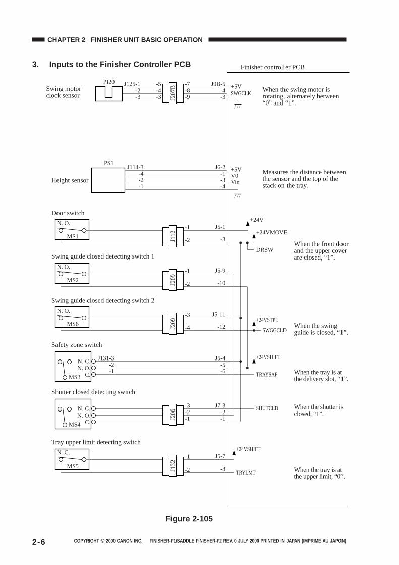
3. Inputs to the Finisher Controller PCB
MS3
N. C.N. O.
C.
MS1
N. O. +24V
+24VSHIFT
+24VSHIFT
+24VSTPL
+24VMOVE
DRSW
TRAYSAF
SHUTCLD
TRYLMT
SWGGCLD
PI20
PS1
-3
J5-1
SWGCLK+5VJ9B-5
-4-3
J125-1
J207
B
-2-3
+5VV0Vin
J6-2-1-3
J114-3-4-2
-4-1
-5-4-3
-7-8-9
J5-4-5-6
J131-3-2-1
J112
-1
-2
MS2
N. O.
-10
J5-9
J209
-1
-2
MS6
MS4
N. C.N. O.
C.
J7-3-2-1J2
06
-3-2-1
N. O.
-12
J5-11
J209
-3
-4
MS5
N. C.
-8
J5-7
J132
-1
-2
Swing motor clock sensor
Height sensor
Door switch
Swing guide closed detecting switch 1
Swing guide closed detecting switch 2
Safety zone switch
Shutter closed detecting switch
Tray upper limit detecting switch
Finisher controller PCB
When the swing motor is rotating, alternately between “0” and “1”.
Measures the distance between the sensor and the top of the stack on the tray.
When the front door and the upper cover are closed, “1”.
When the swing guide is closed, “1”.
When the tray is at the delivery slot, “1”.
When the shutter is closed, “1”.
When the tray is at the upper limit, “0”.
Figure 2-105
COPYRIGHT © 2000 CANON INC. FINISHER-F1/SADDLE FINISHER-F2 REV. 0 JULY 2000 PRINTED IN JAPAN (IMPRIME AU JAPON) 2-7
CHAPTER 2 FINISHER UNIT BASIC OPERATION
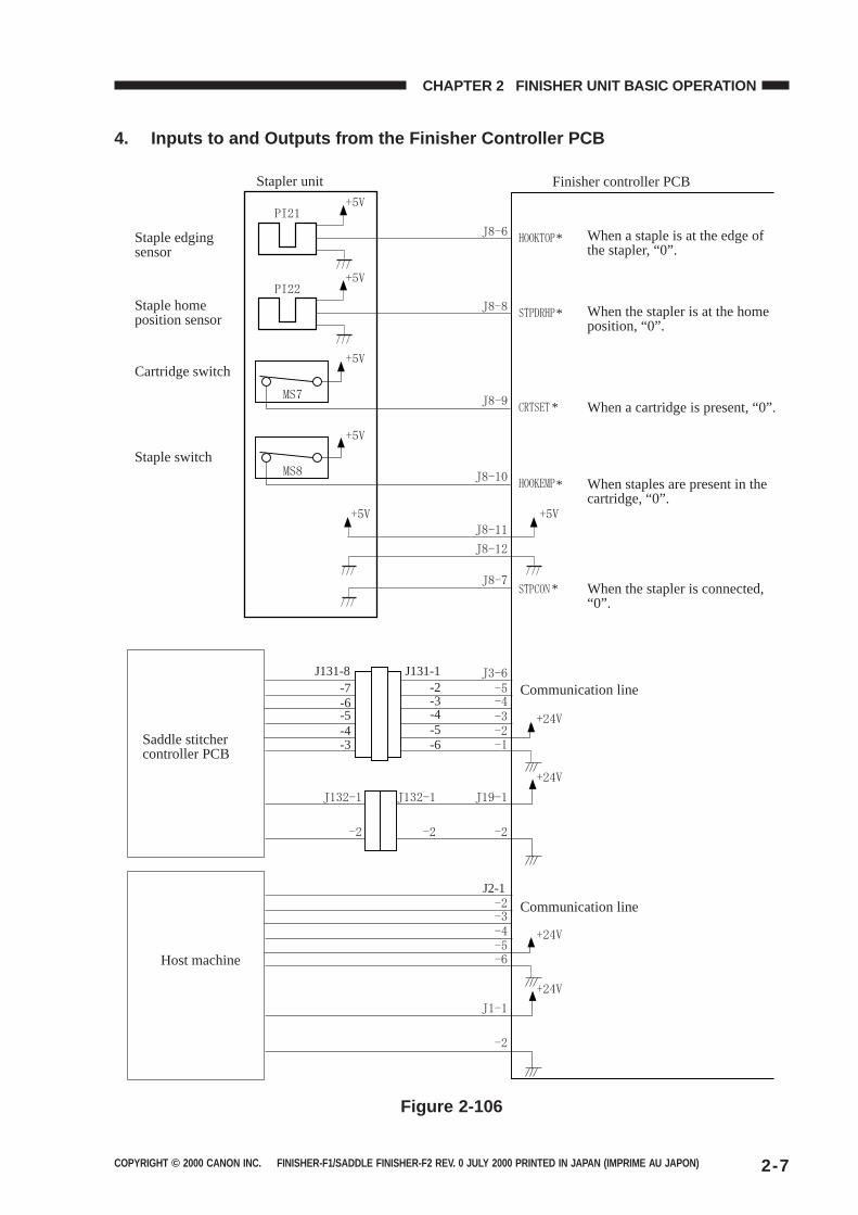
4. Inputs to and Outputs from the Finisher Controller PCB
J131-8 J131-1
J2-1
-7-6-5-4-3
-2-3-4-5-6
*
*
*
*
*
Stapler unit
Staple edging sensor
Staple home position sensor
Cartridge switch
Staple switch
Saddle stitcher controller PCB
Host machine
Finisher controller PCB
When a staple is at the edge of the stapler, “0”.
When the stapler is at the home position, “0”.
When a cartridge is present, “0”.
When staples are present in the cartridge, “0”.
When the stapler is connected, “0”.
Communication line
Communication line
Figure 2-106
COPYRIGHT © 2000 CANON INC. FINISHER-F1/SADDLE FINISHER-F2 REV. 0 JULY 2000 PRINTED IN JAPAN (IMPRIME AU JAPON)2-8
CHAPTER 2 FINISHER UNIT BASIC OPERATION
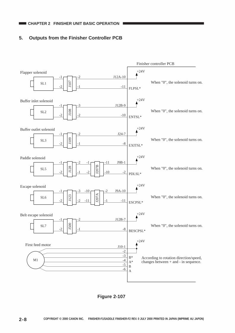
5. Outputs from the Finisher Controller PCB
SL1
J107
-1 -2
+24V
FLPSL*-2
J12A-10
-11-1
SL2
J108
-1 -3
+24V
ENTSL*-2
J12B-9
-10-2
SL3
J109
-1 -2
+24V
EXITSL*-2
J24-7
-8-1
SL5
J128
-1 -2
+24V
PDLSL*-2
J9B-1
-2-1
SL6
J123
-1 -3
+24V
ESCPSL*-2
J9A-10
-11-2
J207
B
-1 -11
-2 -10
J207
A
-10 -2
-11 -1
SL7
J500
-1 -2
+24V
BESCPSL*-2
J12B-7
-8
+24V
J10-1-2
B*-3
A*-4
B-5
A-6
-1
M1
Flapper solenoid
Buffer inlet solenoid
Buffer outlet solenoid
Paddle solenoid
Escape solenoid
Belt escape solenoid
First feed motor
Finisher controller PCB
When "0", the solenoid turns on.
When "0", the solenoid turns on.
When "0", the solenoid turns on.
When "0", the solenoid turns on.
When "0", the solenoid turns on.
When "0", the solenoid turns on.
According to rotation direction/speed, changes between + and - in sequence.
Figure 2-107
COPYRIGHT © 2000 CANON INC. FINISHER-F1/SADDLE FINISHER-F2 REV. 0 JULY 2000 PRINTED IN JAPAN (IMPRIME AU JAPON) 2-9
CHAPTER 2 FINISHER UNIT BASIC OPERATION
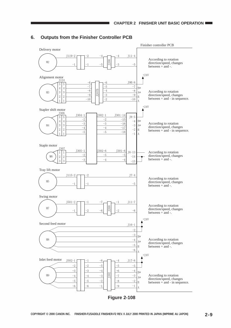
6. Outputs from the Finisher Controller PCB
Delivery motor
Alignment motor
Stapler shift motor
Staple motor
Tray lift motor
Swing motor
Second feed motor
Inlet feed motor
Finisher controller PCB
According to rotation direction/speed, changes between + and -.
According to rotation direction/speed, changes between + and - in sequence.
According to rotation direction/speed, changes between + and - in sequence.
According to rotation direction/speed, changes between + and -.
According to rotation direction/speed, changes between + and -.
According to rotation direction/speed, changes between + and -.
According to rotation direction/speed, changes between + and - in sequence.
According to rotation direction/speed, changes between + and -.
Figure 2-108
COPYRIGHT © 2000 CANON INC. FINISHER-F1/SADDLE FINISHER-F2 REV. 0 JULY 2000 PRINTED IN JAPAN (IMPRIME AU JAPON)2-10
CHAPTER 2 FINISHER UNIT BASIC OPERATION
II. FEED/DRIVE SYSTEM
A. Outline
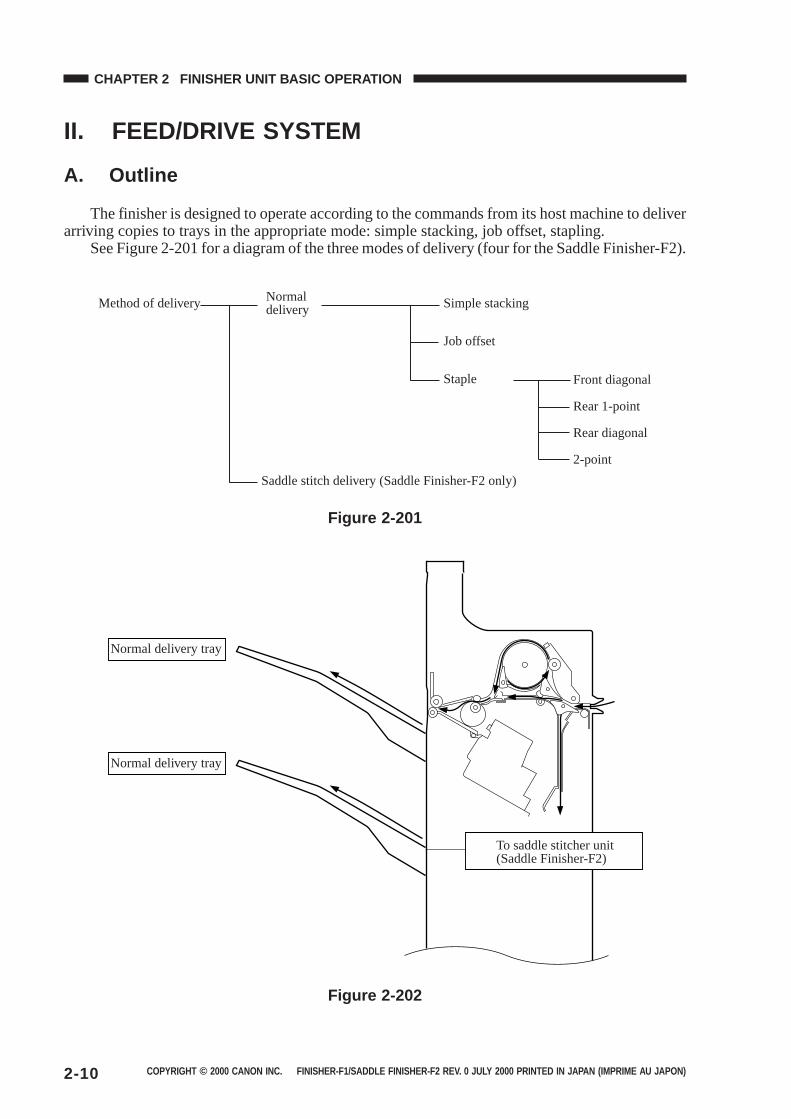
The finisher is designed to operate according to the commands from its host machine to deliverarriving copies to trays in the appropriate mode: simple stacking, job offset, stapling.
See Figure 2-201 for a diagram of the three modes of delivery (four for the Saddle Finisher-F2).
Method of delivery Normal delivery Simple stacking
Job offset
Staple Front diagonal
Rear 1-point
Rear diagonal
2-point
Saddle stitch delivery (Saddle Finisher-F2 only)
Figure 2-201
Normal delivery tray
Normal delivery tray
To saddle stitcher unit(Saddle Finisher-F2)
Figure 2-202

COPYRIGHT © 2000 CANON INC. FINISHER-F1/SADDLE FINISHER-F2 REV. 0 JULY 2000 PRINTED IN JAPAN (IMPRIME AU JAPON) 2-11
CHAPTER 2 FINISHER UNIT BASIC OPERATION
1. Normal Deliverya. Simple Stacking
The finisher delivers copies directly to the tray.
Tray Tray
CopiesCopies
Delivery roller
Feed roller 2
Feed roller 1
Figure 2-203

COPYRIGHT © 2000 CANON INC. FINISHER-F1/SADDLE FINISHER-F2 REV. 0 JULY 2000 PRINTED IN JAPAN (IMPRIME AU JAPON)2-12
CHAPTER 2 FINISHER UNIT BASIC OPERATION
b. Job OffsetThe finisher forwards all copies of each sort job to the stapling tray. The first sort job on the
stapling tray is delivered with a shift to the front of about 30 mm, and the second sort job is deliv-ered without being shifted. Whether the first copy or the last copy of a sort job should be shifted isdetermined by the host machine.
Tray
Each sort job is stacked alternately.
Figure 2-204
Swing guide
Stapling tray
Delivery roller
Stopper
Feed roller 1
Figure 2-205
Results of Delivering 4 Sets
Direction of delivery
Copies handled by job offset
Figure 2-206
COPYRIGHT © 2000 CANON INC. FINISHER-F1/SADDLE FINISHER-F2 REV. 0 JULY 2000 PRINTED IN JAPAN (IMPRIME AU JAPON) 2-13
CHAPTER 2 FINISHER UNIT BASIC OPERATION
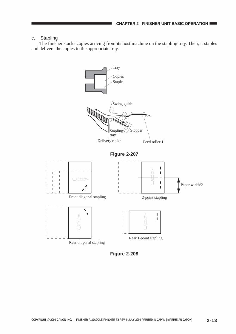
c. StaplingThe finisher stacks copies arriving from its host machine on the stapling tray. Then, it staples
and delivers the copies to the appropriate tray.
Tray
CopiesStaple
Swing guide
Delivery roller
Stapling tray
Stopper
Feed roller 1
Figure 2-207
Front diagonal stapling
Rear diagonal stapling
2-point stapling
Paper width/2
Rear 1-point stapling
Figure 2-208
COPYRIGHT © 2000 CANON INC. FINISHER-F1/SADDLE FINISHER-F2 REV. 0 JULY 2000 PRINTED IN JAPAN (IMPRIME AU JAPON)2-14
CHAPTER 2 FINISHER UNIT BASIC OPERATION
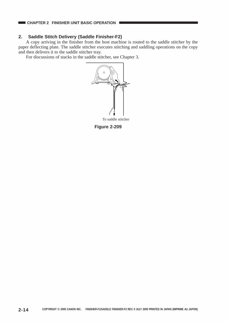
2. Saddle Stitch Delivery (Saddle Finisher-F2)A copy arriving in the finisher from the host machine is routed to the saddle stitcher by the
paper deflecting plate. The saddle stitcher executes stitching and saddling operations on the copyand then delivers it to the saddle stitcher tray.
For discussions of stacks in the saddle stitcher, see Chapter 3.
To saddle stitcher
Figure 2-209
COPYRIGHT © 2000 CANON INC. FINISHER-F1/SADDLE FINISHER-F2 REV. 0 JULY 2000 PRINTED IN JAPAN (IMPRIME AU JAPON) 2-15
CHAPTER 2 FINISHER UNIT BASIC OPERATION
B. Type of Delivery Paths
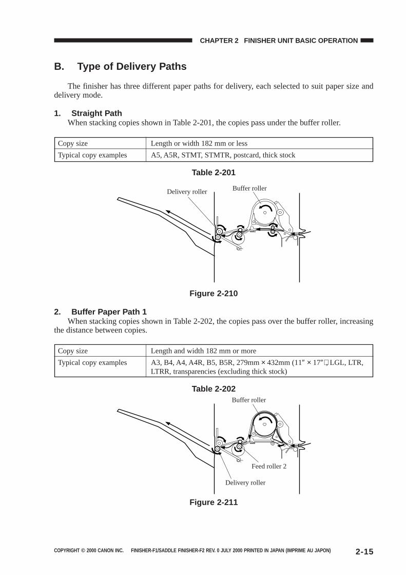
The finisher has three different paper paths for delivery, each selected to suit paper size anddelivery mode.
1. Straight PathWhen stacking copies shown in Table 2-201, the copies pass under the buffer roller.
Copy size Length or width 182 mm or less
Typical copy examples A5, A5R, STMT, STMTR, postcard, thick stock
Table 2-201
Delivery roller Buffer roller
Figure 2-210
2. Buffer Paper Path 1When stacking copies shown in Table 2-202, the copies pass over the buffer roller, increasing
the distance between copies.
Copy size Length and width 182 mm or more
Typical copy examples A3, B4, A4, A4R, B5, B5R, 279mm × 432mm (11″ × 17″), LGL, LTR,LTRR, transparencies (excluding thick stock)
Table 2-202Buffer roller
Feed roller 2
Delivery roller
Figure 2-211
COPYRIGHT © 2000 CANON INC. FINISHER-F1/SADDLE FINISHER-F2 REV. 0 JULY 2000 PRINTED IN JAPAN (IMPRIME AU JAPON)2-16
CHAPTER 2 FINISHER UNIT BASIC OPERATION
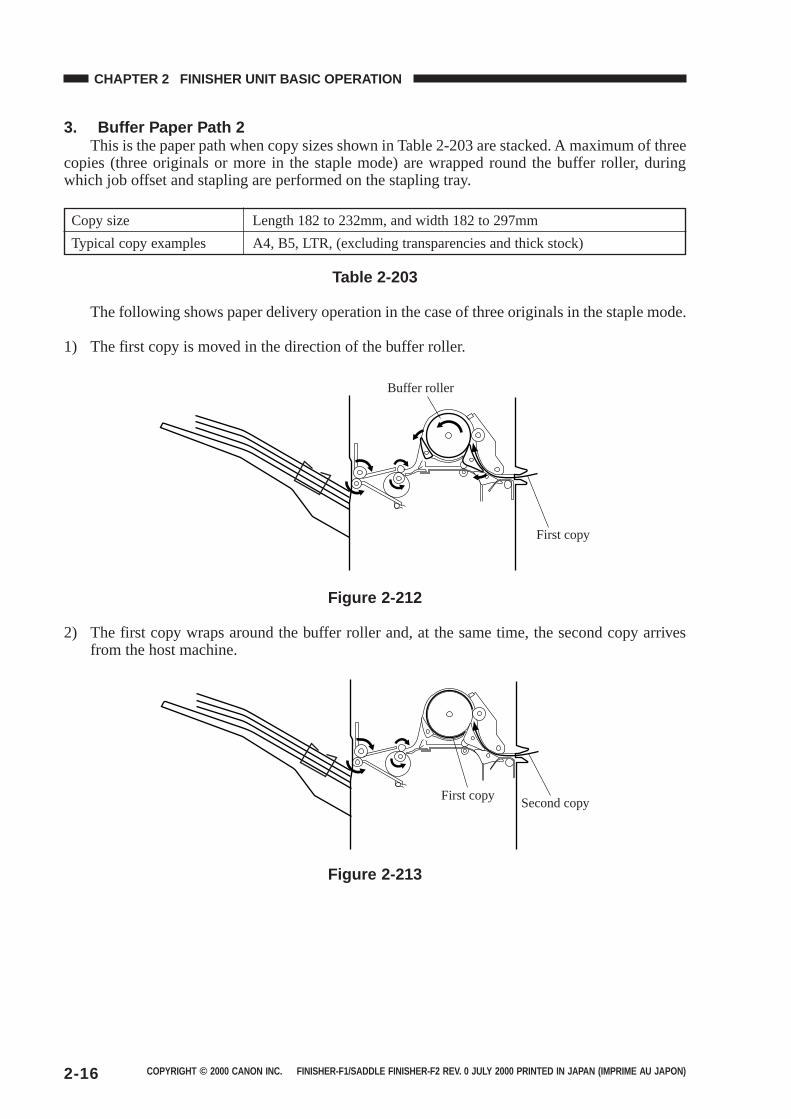
3. Buffer Paper Path 2This is the paper path when copy sizes shown in Table 2-203 are stacked. A maximum of three
copies (three originals or more in the staple mode) are wrapped round the buffer roller, duringwhich job offset and stapling are performed on the stapling tray.
Copy size Length 182 to 232mm, and width 182 to 297mm
Typical copy examples A4, B5, LTR, (excluding transparencies and thick stock)
Table 2-203
The following shows paper delivery operation in the case of three originals in the staple mode.
1) The first copy is moved in the direction of the buffer roller.
Buffer roller
First copy
Figure 2-212
2) The first copy wraps around the buffer roller and, at the same time, the second copy arrivesfrom the host machine.
First copySecond copy
Figure 2-213
COPYRIGHT © 2000 CANON INC. FINISHER-F1/SADDLE FINISHER-F2 REV. 0 JULY 2000 PRINTED IN JAPAN (IMPRIME AU JAPON) 2-17
CHAPTER 2 FINISHER UNIT BASIC OPERATION
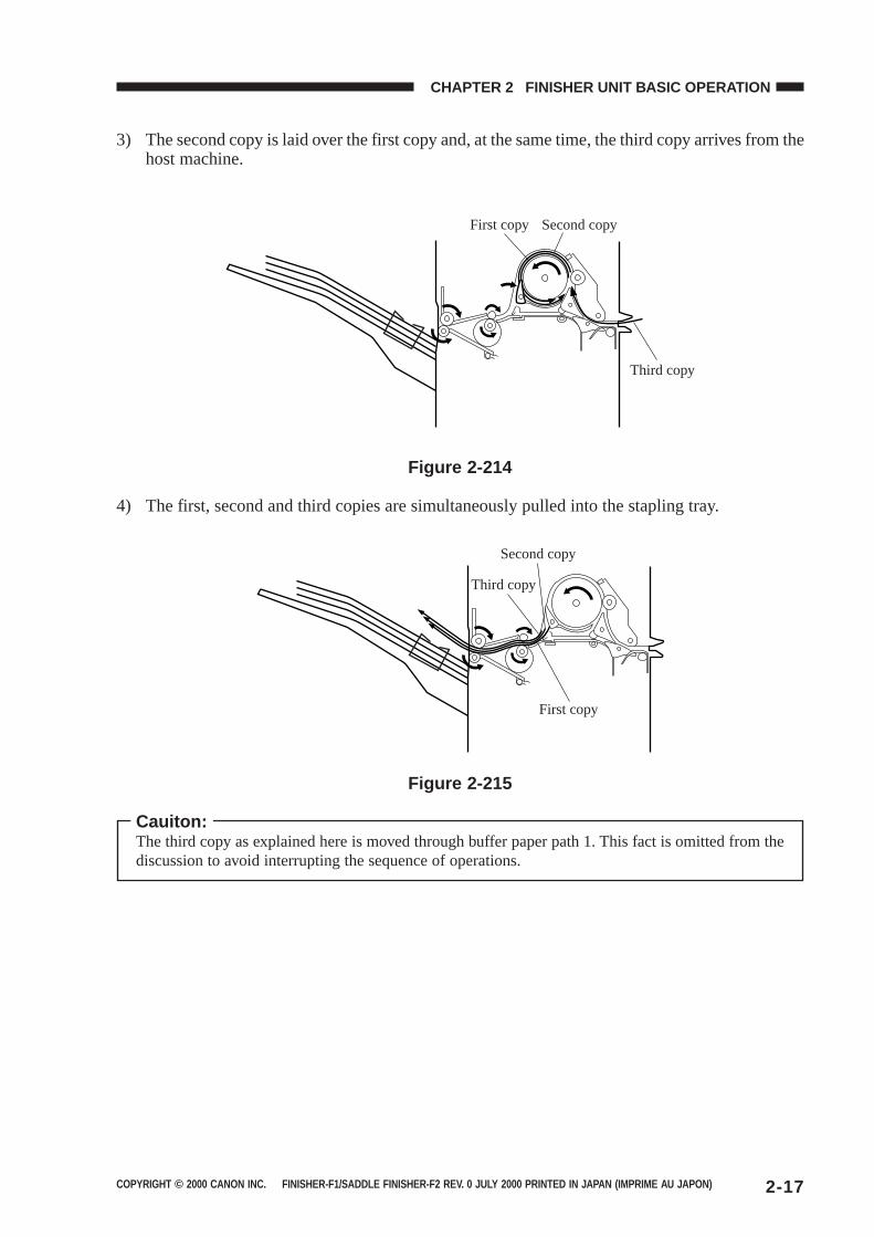
3) The second copy is laid over the first copy and, at the same time, the third copy arrives from thehost machine.
First copy Second copy
Third copy
Figure 2-214
4) The first, second and third copies are simultaneously pulled into the stapling tray.
Second copy
Third copy
First copy
Figure 2-215
Cauiton:The third copy as explained here is moved through buffer paper path 1. This fact is omitted from thediscussion to avoid interrupting the sequence of operations.
COPYRIGHT © 2000 CANON INC. FINISHER-F1/SADDLE FINISHER-F2 REV. 0 JULY 2000 PRINTED IN JAPAN (IMPRIME AU JAPON)2-18
CHAPTER 2 FINISHER UNIT BASIC OPERATION
C. Feeding and Delivering
1. OutlineThe finisher moves copies arriving from the host machine to the delivery tray, stapling tray, or
the saddle stitcher unit (Saddle Finisher-F2) according to the mode of delivery. On the stapling tray,the copies are subjected to job offset or stapling as instructed by the host machine.
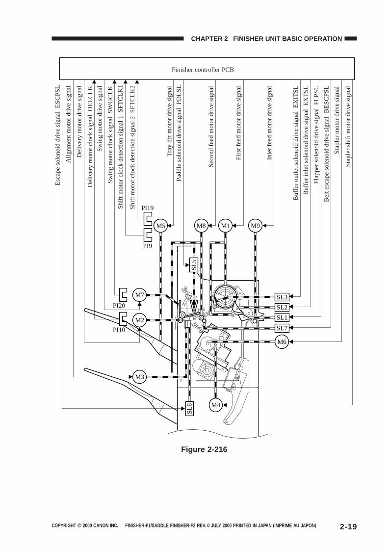
The first feed motor (M1), second feed motor (M8) and inlet feed motor (M9) are steppingmotors, and delivery motor (M2) is a DC motor. These motors are controlled by the microprocessor(CPU) on the finisher controller PCB, and rotate either clockwise or counterclockwise.
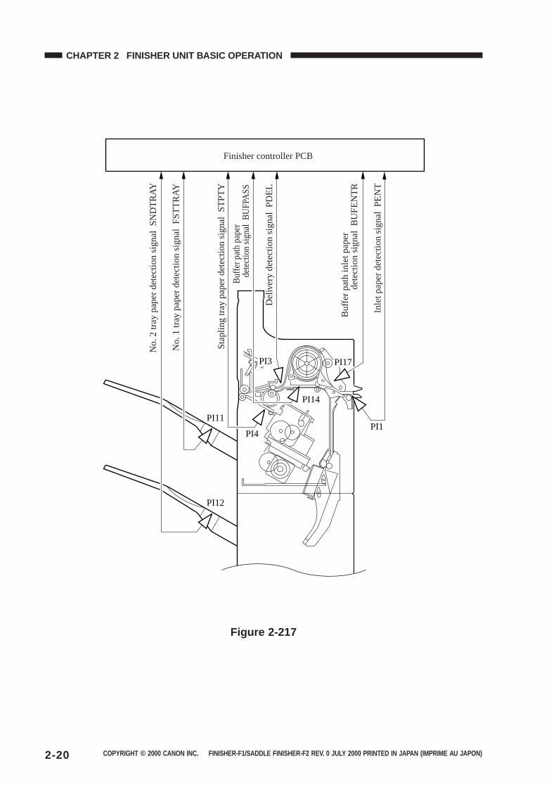
The paper paths are equipped with the following four sensors for detection of paper (arrival,passage):
● Inlet sensor (PI1)● Delivery sensor (PI3)● Stapling tray sensor (PI4)● Buffer path paper sensor (PI14)
In addition, each delivery tray is equipped with a sensor designed to detect the presence/ab-sence of paper on it.
● No.1 tray paper sensor (PI11)● No.2 tray paper sensor (PI12)
If a copy fails to reach or move past each sensor within a specific period of time, the finishercontroller PCB identifies the condition as a jam, and stops the ongoing operation, and at the sametime, informs the host machine of the condition. When all doors are closed after the paper jam isremoved, the buffer path inlet paper sensor (PI17) checks whether or not copies are being detectedin addition to the above four sensors (inlet sensor, delivery sensor, stapling tray sensor and bufferpath paper sensor). If the sensors detect a copy, the finisher unit judges that paper jams have notcompletely been removed, and sends the paper jam removal signal to the host machine again.
COPYRIGHT © 2000 CANON INC. FINISHER-F1/SADDLE FINISHER-F2 REV. 0 JULY 2000 PRINTED IN JAPAN (IMPRIME AU JAPON) 2-19
CHAPTER 2 FINISHER UNIT BASIC OPERATION
Tra
y lif
t mot
or d
rive
sign
al
SL3
SL2
SL1
SL7
M6
M2
M7
PI20
SL6 M4
PI10
PI9
PI19
M1M8 M9
M3
SL5
M5
Esc
ape
sole
noid
driv
e si
gnal
ES
CP
SL
Alig
nmen
t mot
or d
rive
sign
al
Del
iver
y m
otor
driv
e si
gnal
Del
iver
y m
otor
clo
ck s
igna
l D
ELC
LK
Sw
ing
mot
or d
rive
sign
al
Sw
ing
mot
or c
lock
sig
nal
SW
GC
LK
Shi
ft m
otor
clo
ck d
etec
tion
sign
al 1
SF
TC
LK1
Shi
ft m
otor
clo
ck d
etec
tion
sign
al 2
SF
TC
LK2
Pad
dle
sole
noid
driv
e si
gnal
PD
LSL
Sec
ond
feed
mot
or d
rive
sign
al
Firs
t fee
d m
otor
driv
e si
gnal
Inle
t fee
d m
otor
driv
e si
gnal
Buf
fer
outle
t sol
enoi
d dr
ive
sign
al E
XIT
SL
Buf
fer
inle
t sol
enoi
d dr
ive
sign
al E
XT
SL
Fla
pper
sol
enoi
d dr
ive
sign
al F
LPS
L
Bel
t esc
ape
sole
noid
driv
e si
gnal
BE
SC
PS
L
Sta
pler
mot
or d
rive
sign
al
Sta
pler
shi
ft m
otor
driv
e si
gnal
Finisher controller PCB
Figure 2-216
COPYRIGHT © 2000 CANON INC. FINISHER-F1/SADDLE FINISHER-F2 REV. 0 JULY 2000 PRINTED IN JAPAN (IMPRIME AU JAPON)2-20
CHAPTER 2 FINISHER UNIT BASIC OPERATION
PI1
PI14
PI17
PI4
PI3
PI11
PI12
No.
2 tr
ay p
aper
det
ectio
n si
gnal
SN
DT
RA
Y
No.
1 tr
ay p
aper
det
ectio
n si
gnal
FS
TT
RA
Y
Sta
plin
g tr
ay p
aper
det
ectio
n si
gnal
ST
PT
Y
Buf
fer p
ath
pape
r
de
tect
ion
sign
al B
UFP
AS
S
Del
iver
y de
tect
ion
sign
al P
DE
L
Buf
fer
path
inle
t pap
er
dete
ctio
n si
gnal
BU
FE
NT
R
Inle
t pap
er d
etec
tion
sign
al P
EN
T
Finisher controller PCB
Figure 2-217
COPYRIGHT © 2000 CANON INC. FINISHER-F1/SADDLE FINISHER-F2 REV. 0 JULY 2000 PRINTED IN JAPAN (IMPRIME AU JAPON) 2-21
CHAPTER 2 FINISHER UNIT BASIC OPERATION
D. Job Offset
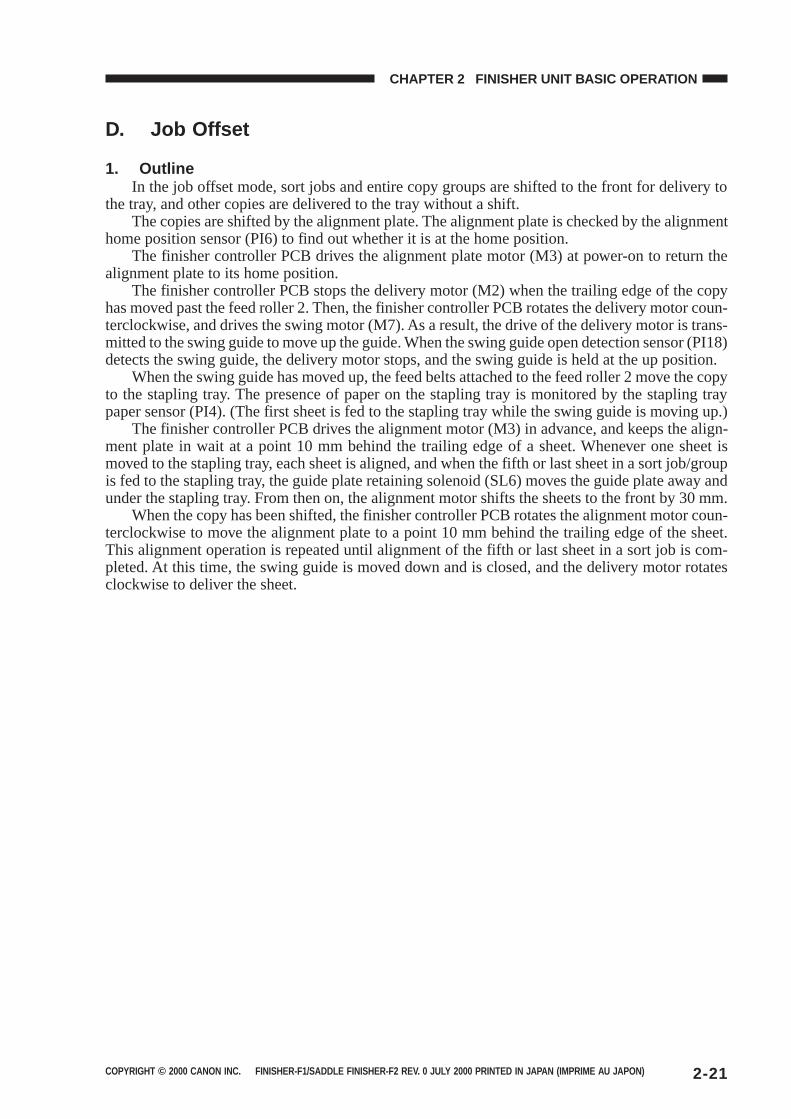
1. OutlineIn the job offset mode, sort jobs and entire copy groups are shifted to the front for delivery to
the tray, and other copies are delivered to the tray without a shift.The copies are shifted by the alignment plate. The alignment plate is checked by the alignment
home position sensor (PI6) to find out whether it is at the home position.The finisher controller PCB drives the alignment plate motor (M3) at power-on to return the
alignment plate to its home position.The finisher controller PCB stops the delivery motor (M2) when the trailing edge of the copy
has moved past the feed roller 2. Then, the finisher controller PCB rotates the delivery motor coun-terclockwise, and drives the swing motor (M7). As a result, the drive of the delivery motor is trans-mitted to the swing guide to move up the guide. When the swing guide open detection sensor (PI18)detects the swing guide, the delivery motor stops, and the swing guide is held at the up position.
When the swing guide has moved up, the feed belts attached to the feed roller 2 move the copyto the stapling tray. The presence of paper on the stapling tray is monitored by the stapling traypaper sensor (PI4). (The first sheet is fed to the stapling tray while the swing guide is moving up.)
The finisher controller PCB drives the alignment motor (M3) in advance, and keeps the align-ment plate in wait at a point 10 mm behind the trailing edge of a sheet. Whenever one sheet ismoved to the stapling tray, each sheet is aligned, and when the fifth or last sheet in a sort job/groupis fed to the stapling tray, the guide plate retaining solenoid (SL6) moves the guide plate away andunder the stapling tray. From then on, the alignment motor shifts the sheets to the front by 30 mm.
When the copy has been shifted, the finisher controller PCB rotates the alignment motor coun-terclockwise to move the alignment plate to a point 10 mm behind the trailing edge of the sheet.This alignment operation is repeated until alignment of the fifth or last sheet in a sort job is com-pleted. At this time, the swing guide is moved down and is closed, and the delivery motor rotatesclockwise to deliver the sheet.
COPYRIGHT © 2000 CANON INC. FINISHER-F1/SADDLE FINISHER-F2 REV. 0 JULY 2000 PRINTED IN JAPAN (IMPRIME AU JAPON)2-22
CHAPTER 2 FINISHER UNIT BASIC OPERATION
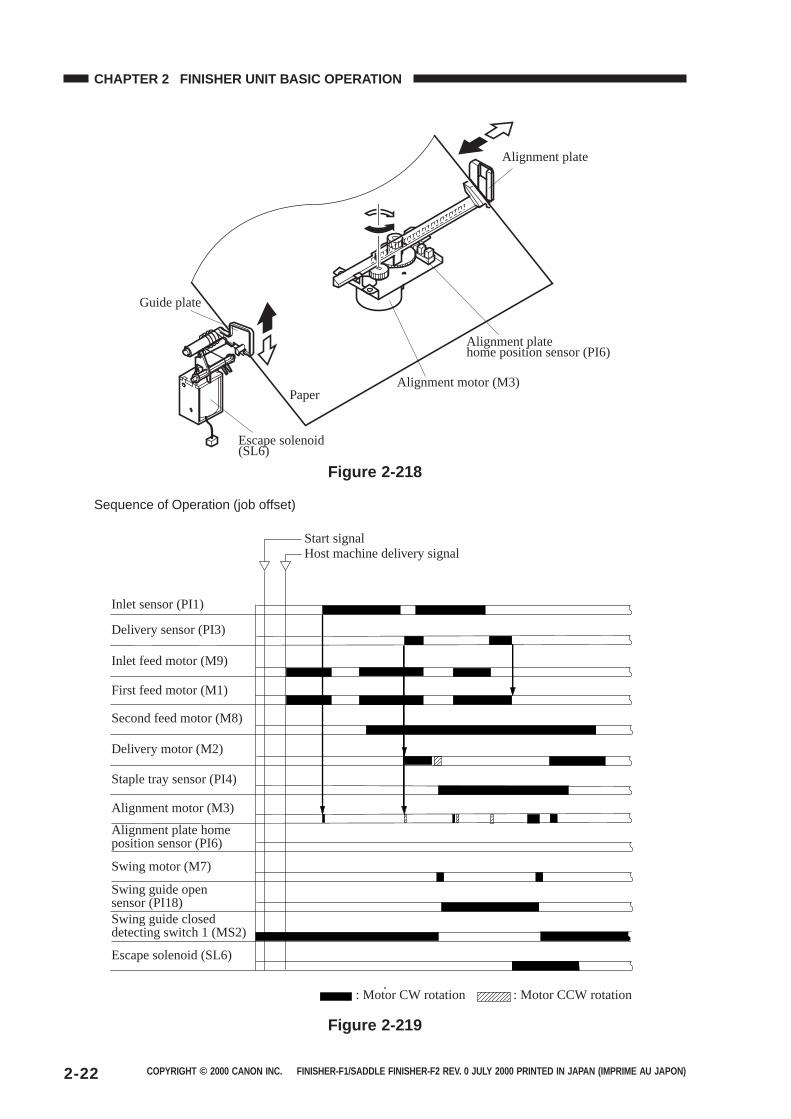
Guide plate
Escape solenoid(SL6)
Paper
Alignment plate
Alignment plate home position sensor (PI6)
Alignment motor (M3)
Figure 2-218
Sequence of Operation (job offset)
Delivery motor (M2)
First feed motor (M1)
Inlet sensor (PI1)
Start signalHost machine delivery signal
Delivery sensor (PI3)
Staple tray sensor (PI4)
Second feed motor (M8)
Alignment motor (M3)
Alignment plate home position sensor (PI6)
Swing guide open sensor (PI18)Swing guide closed detecting switch 1 (MS2)
Swing motor (M7)
Inlet feed motor (M9)
Escape solenoid (SL6)
: Motor CW rotation : Motor CCW rotation
Figure 2-219
COPYRIGHT © 2000 CANON INC. FINISHER-F1/SADDLE FINISHER-F2 REV. 0 JULY 2000 PRINTED IN JAPAN (IMPRIME AU JAPON) 2-23
CHAPTER 2 FINISHER UNIT BASIC OPERATION
2. Flow of Job Offset Operations
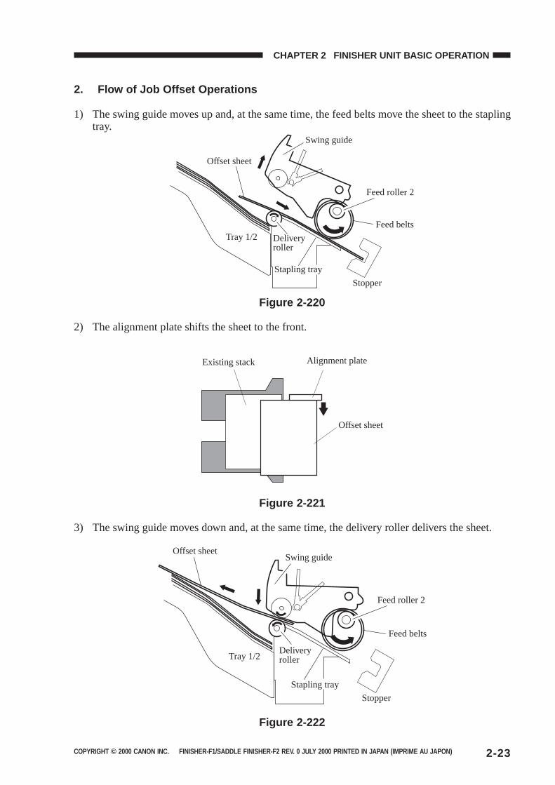
1) The swing guide moves up and, at the same time, the feed belts move the sheet to the staplingtray.
Offset sheet
Swing guide
Tray 1/2 Delivery roller
Stapling tray
Feed roller 2
Feed belts
Stopper
Figure 2-220
2) The alignment plate shifts the sheet to the front.
Existing stack Alignment plate
Offset sheet
Figure 2-221
3) The swing guide moves down and, at the same time, the delivery roller delivers the sheet.
Offset sheetSwing guide
Feed roller 2
Feed belts
Tray 1/2Delivery roller
Stapling tray
Stopper
Figure 2-222
COPYRIGHT © 2000 CANON INC. FINISHER-F1/SADDLE FINISHER-F2 REV. 0 JULY 2000 PRINTED IN JAPAN (IMPRIME AU JAPON)2-24
CHAPTER 2 FINISHER UNIT BASIC OPERATION
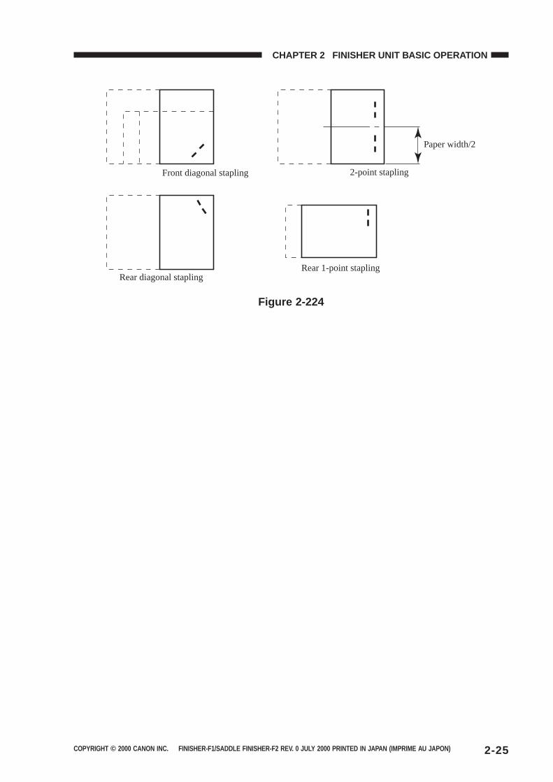
E. Staple Operation
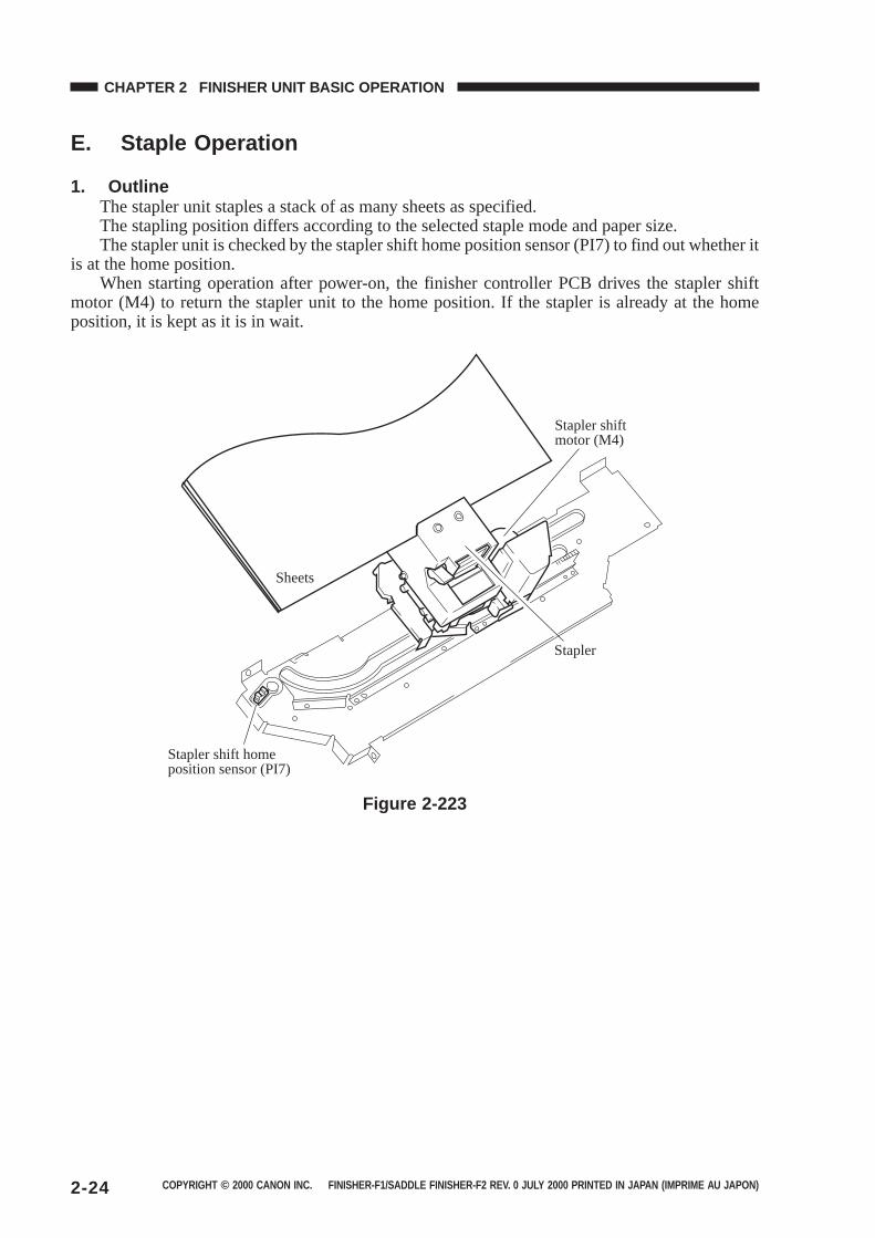
1. OutlineThe stapler unit staples a stack of as many sheets as specified.The stapling position differs according to the selected staple mode and paper size.The stapler unit is checked by the stapler shift home position sensor (PI7) to find out whether it
is at the home position.When starting operation after power-on, the finisher controller PCB drives the stapler shift
motor (M4) to return the stapler unit to the home position. If the stapler is already at the homeposition, it is kept as it is in wait.
Sheets
Stapler shift home position sensor (PI7)
Stapler shift motor (M4)
Stapler
Figure 2-223
COPYRIGHT © 2000 CANON INC. FINISHER-F1/SADDLE FINISHER-F2 REV. 0 JULY 2000 PRINTED IN JAPAN (IMPRIME AU JAPON) 2-25
CHAPTER 2 FINISHER UNIT BASIC OPERATION
Front diagonal stapling 2-point stapling
Paper width/2
Rear diagonal staplingRear 1-point stapling
Figure 2-224
COPYRIGHT © 2000 CANON INC. FINISHER-F1/SADDLE FINISHER-F2 REV. 0 JULY 2000 PRINTED IN JAPAN (IMPRIME AU JAPON)2-26
CHAPTER 2 FINISHER UNIT BASIC OPERATION
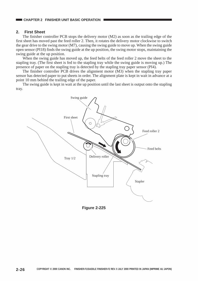
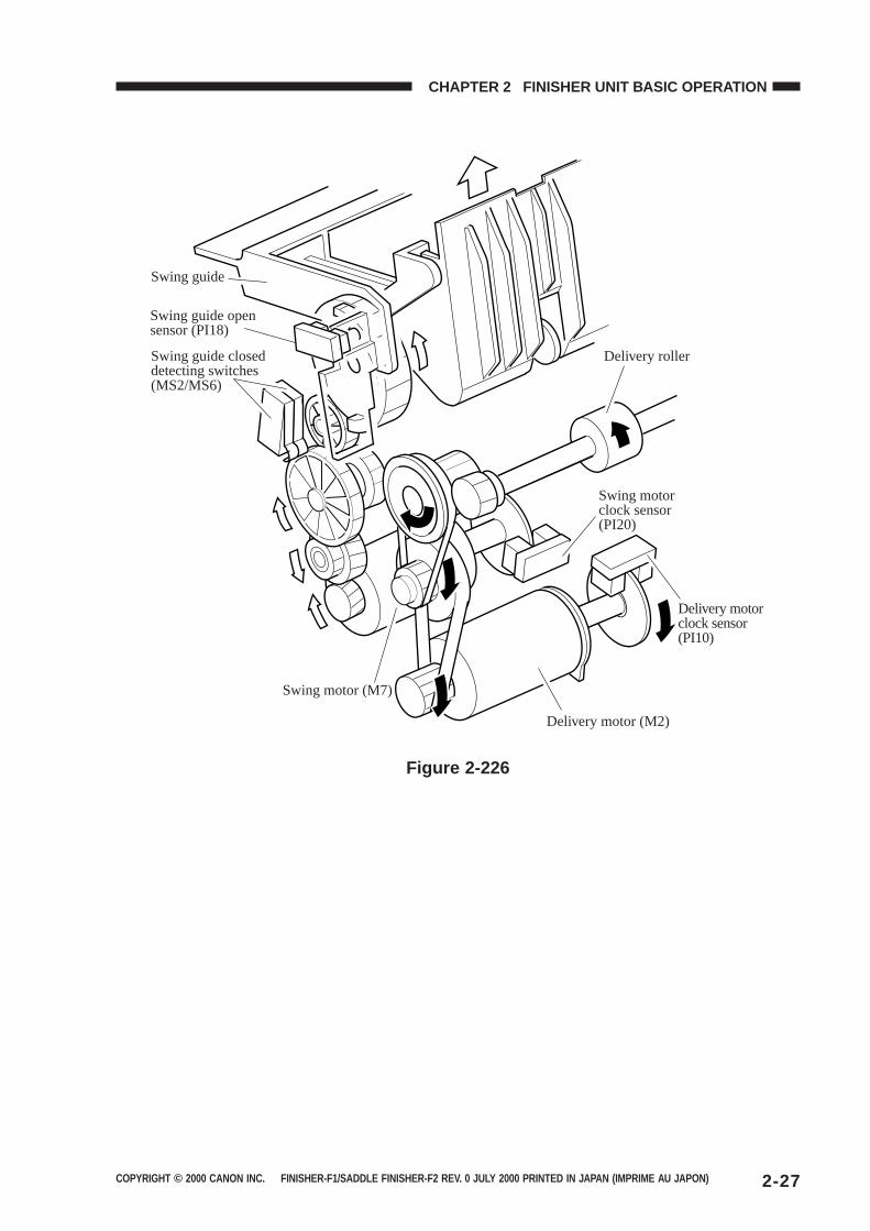
2. First SheetThe finisher controller PCB stops the delivery motor (M2) as soon as the trailing edge of the
first sheet has moved past the feed roller 2. Then, it rotates the delivery motor clockwise to switchthe gear drive to the swing motor (M7), causing the swing guide to move up. When the swing guideopen sensor (PI18) finds the swing guide at the up position, the swing motor stops, maintaining theswing guide at the up position.
When the swing guide has moved up, the feed belts of the feed roller 2 move the sheet to thestapling tray. (The first sheet is fed to the stapling tray while the swing guide is moving up.) Thepresence of paper on the stapling tray is detected by the stapling tray paper sensor (PI4).
The finisher controller PCB drives the alignment motor (M3) when the stapling tray papersensor has detected paper to put sheets in order. The alignment plate is kept in wait in advance at apoint 10 mm behind the trailing edge of the paper.
The swing guide is kept in wait at the up position until the last sheet is output onto the staplingtray.
Swing guide
First sheet
Tray 1/2 Delivery roller
Stapling tray
Feed roller 2
Feed belts
Stapler
Figure 2-225
COPYRIGHT © 2000 CANON INC. FINISHER-F1/SADDLE FINISHER-F2 REV. 0 JULY 2000 PRINTED IN JAPAN (IMPRIME AU JAPON) 2-27
CHAPTER 2 FINISHER UNIT BASIC OPERATION
Swing guide
Swing guide open sensor (PI18)
Swing guide closed detecting switches (MS2/MS6)
Delivery roller
Swing motor clock sensor (PI20)
Delivery motor clock sensor (PI10)
Delivery motor (M2)
Swing motor (M7)
Figure 2-226
COPYRIGHT © 2000 CANON INC. FINISHER-F1/SADDLE FINISHER-F2 REV. 0 JULY 2000 PRINTED IN JAPAN (IMPRIME AU JAPON)2-28
CHAPTER 2 FINISHER UNIT BASIC OPERATION
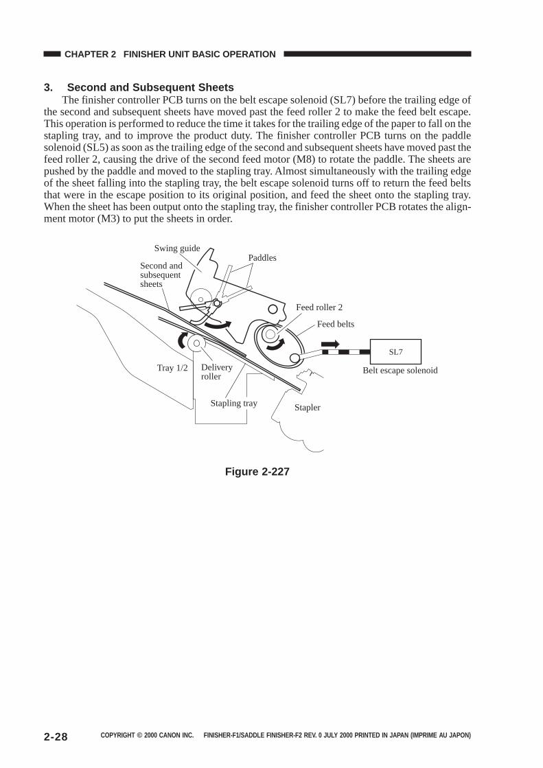
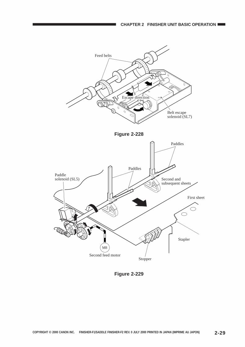
3. Second and Subsequent SheetsThe finisher controller PCB turns on the belt escape solenoid (SL7) before the trailing edge of
the second and subsequent sheets have moved past the feed roller 2 to make the feed belt escape.This operation is performed to reduce the time it takes for the trailing edge of the paper to fall on thestapling tray, and to improve the product duty. The finisher controller PCB turns on the paddlesolenoid (SL5) as soon as the trailing edge of the second and subsequent sheets have moved past thefeed roller 2, causing the drive of the second feed motor (M8) to rotate the paddle. The sheets arepushed by the paddle and moved to the stapling tray. Almost simultaneously with the trailing edgeof the sheet falling into the stapling tray, the belt escape solenoid turns off to return the feed beltsthat were in the escape position to its original position, and feed the sheet onto the stapling tray.When the sheet has been output onto the stapling tray, the finisher controller PCB rotates the align-ment motor (M3) to put the sheets in order.
SL7
Swing guide
Second and subsequent sheets
Paddles
Feed roller 2
Feed belts
Belt escape solenoidTray 1/2 Delivery roller
Stapling tray Stapler
Figure 2-227
COPYRIGHT © 2000 CANON INC. FINISHER-F1/SADDLE FINISHER-F2 REV. 0 JULY 2000 PRINTED IN JAPAN (IMPRIME AU JAPON) 2-29
CHAPTER 2 FINISHER UNIT BASIC OPERATION
Feed belts
Escape direction
Belt escape solenoid (SL7)
Figure 2-228
M8
Paddles
Paddles
Paddle solenoid (SL5) Second and
subsequent sheets
First sheet
Stapler
StopperSecond feed motor
Figure 2-229

COPYRIGHT © 2000 CANON INC. FINISHER-F1/SADDLE FINISHER-F2 REV. 0 JULY 2000 PRINTED IN JAPAN (IMPRIME AU JAPON)2-30
CHAPTER 2 FINISHER UNIT BASIC OPERATION
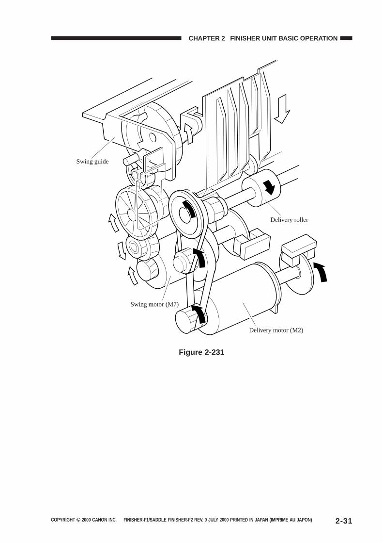
4. Last SheetWhen the last sheet has been put in order, the finisher controller PCB turns on the alignment
motor (M3) to move the alignment plate to the alignment position (to butt the plate against thestack). Then, the finisher controller PCB rotates the swing motor (M7) counterclockwise to movedown the swing guide.
The finisher controller PCB moves the stapler according to the staple mode for stapling.From then on, it rotates the delivery motor (M2) clockwise to deliver the stack to the tray.
Swing guide
Sheets
Tray 1/2 Delivery roller
Stapling tray
Feed roller 2
Feed belts
Stapler
Figure 2-230
COPYRIGHT © 2000 CANON INC. FINISHER-F1/SADDLE FINISHER-F2 REV. 0 JULY 2000 PRINTED IN JAPAN (IMPRIME AU JAPON) 2-31
CHAPTER 2 FINISHER UNIT BASIC OPERATION
Swing guide
Swing motor (M7)
Delivery motor (M2)
Delivery roller
Figure 2-231
COPYRIGHT © 2000 CANON INC. FINISHER-F1/SADDLE FINISHER-F2 REV. 0 JULY 2000 PRINTED IN JAPAN (IMPRIME AU JAPON)2-32
CHAPTER 2 FINISHER UNIT BASIC OPERATION
F. Stapler Unit
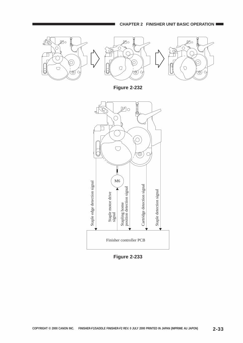
Stapling is executed by the stapler motor (M6). A single rotation of the cam by the motorresults in one stapling operation.
The cam is checked by the stapling home position sensor (PI22) to find out whether it is at thehome position.
The stapler motor is controlled by the microprocessor (Q1) on the finisher controller so that itis rotated clockwise or counterclockwise.
When the stapling home position sensor is off, the finisher controller PCB rotates the staplermotor clockwise until the sensor turns on so as to return the stapling cam to its initial state.
The presence/absence of the staple cartridge is detected by the staple cartridge switch (MS8).The presence/absence of staples inside the staple cartridge is detected by the staple detecting switch(MS9). The staple edge sensor (PI21) is used to find out whether a staple has been edged out to theend of the cartridge.
The finisher controller PCB does not drive the stapler motor (M6) unless the swing guideclosed detecting switch 2 (MS6) is on (i.e., the swing guide is closed). This is to protect againstinjuries that could occur when a finger is stuck inside the stapler.
COPYRIGHT © 2000 CANON INC. FINISHER-F1/SADDLE FINISHER-F2 REV. 0 JULY 2000 PRINTED IN JAPAN (IMPRIME AU JAPON) 2-33
CHAPTER 2 FINISHER UNIT BASIC OPERATION
Figure 2-232S
tapl
e ed
ge d
etec
tion
sign
al
Sta
ple
mot
or d
rive
sign
al
Sta
plin
g ho
me
posi
tion
dete
ctio
n si
gnal
Car
trid
ge d
etec
tion
sign
al
Sta
ple
dete
ctio
n si
gnal
Finisher controller PCB
M6
Figure 2-233
COPYRIGHT © 2000 CANON INC. FINISHER-F1/SADDLE FINISHER-F2 REV. 0 JULY 2000 PRINTED IN JAPAN (IMPRIME AU JAPON)2-34
CHAPTER 2 FINISHER UNIT BASIC OPERATION
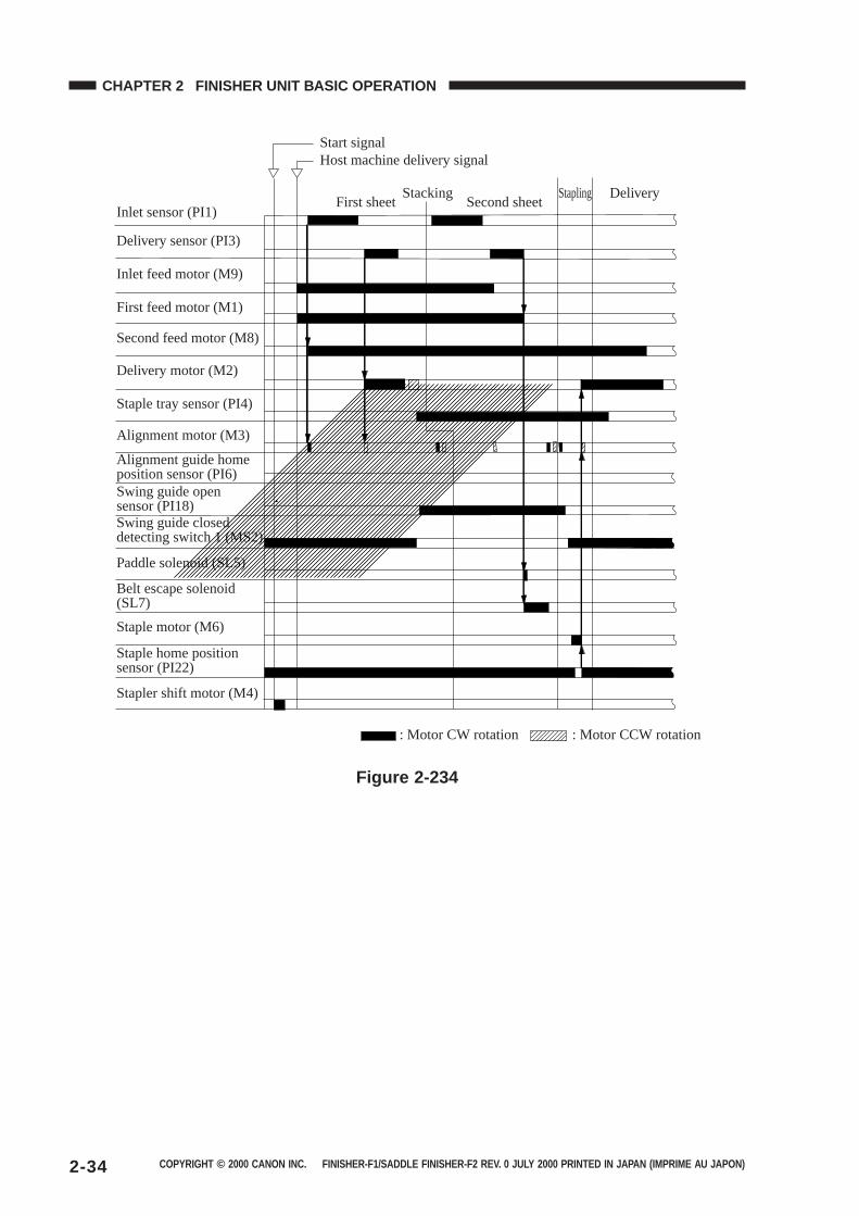
Start signalHost machine delivery signal
First sheetStacking
Second sheetStapling Delivery
Delivery motor (M2)
First feed motor (M1)
Inlet feed motor (M9)
Second feed motor (M8)
Inlet sensor (PI1)
Delivery sensor (PI3)
Alignment motor (M3)
Alignment guide home position sensor (PI6)Swing guide open sensor (PI18)
Staple tray sensor (PI4)
Swing guide closed detecting switch 1 (MS2)
Paddle solenoid (SL5)
Stapler shift motor (M4)
Staple motor (M6)
Belt escape solenoid (SL7)
Staple home positionsensor (PI22)
: Motor CW rotation : Motor CCW rotation
Figure 2-234
COPYRIGHT © 2000 CANON INC. FINISHER-F1/SADDLE FINISHER-F2 REV. 0 JULY 2000 PRINTED IN JAPAN (IMPRIME AU JAPON) 2-35
CHAPTER 2 FINISHER UNIT BASIC OPERATION
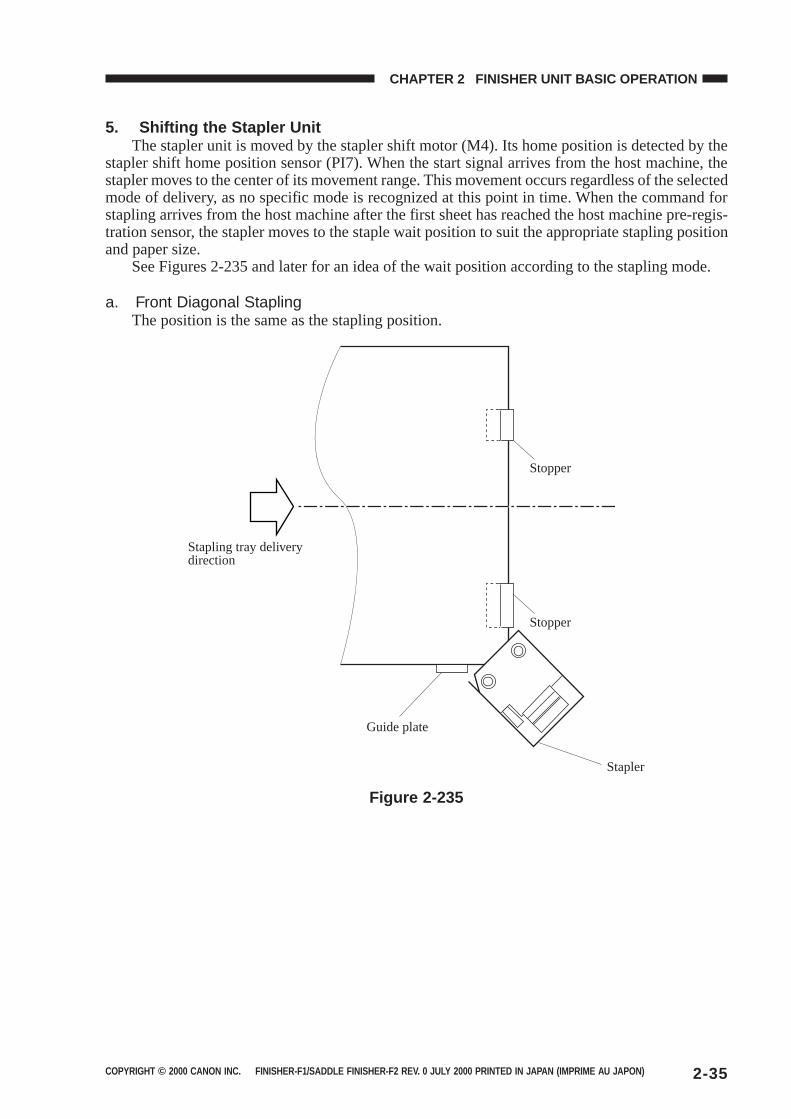
5. Shifting the Stapler UnitThe stapler unit is moved by the stapler shift motor (M4). Its home position is detected by the
stapler shift home position sensor (PI7). When the start signal arrives from the host machine, thestapler moves to the center of its movement range. This movement occurs regardless of the selectedmode of delivery, as no specific mode is recognized at this point in time. When the command forstapling arrives from the host machine after the first sheet has reached the host machine pre-regis-tration sensor, the stapler moves to the staple wait position to suit the appropriate stapling positionand paper size.
See Figures 2-235 and later for an idea of the wait position according to the stapling mode.
a. Front Diagonal StaplingThe position is the same as the stapling position.
Stapling tray delivery direction
Stopper
Stopper
Guide plate
Stapler
Figure 2-235
COPYRIGHT © 2000 CANON INC. FINISHER-F1/SADDLE FINISHER-F2 REV. 0 JULY 2000 PRINTED IN JAPAN (IMPRIME AU JAPON)2-36
CHAPTER 2 FINISHER UNIT BASIC OPERATION
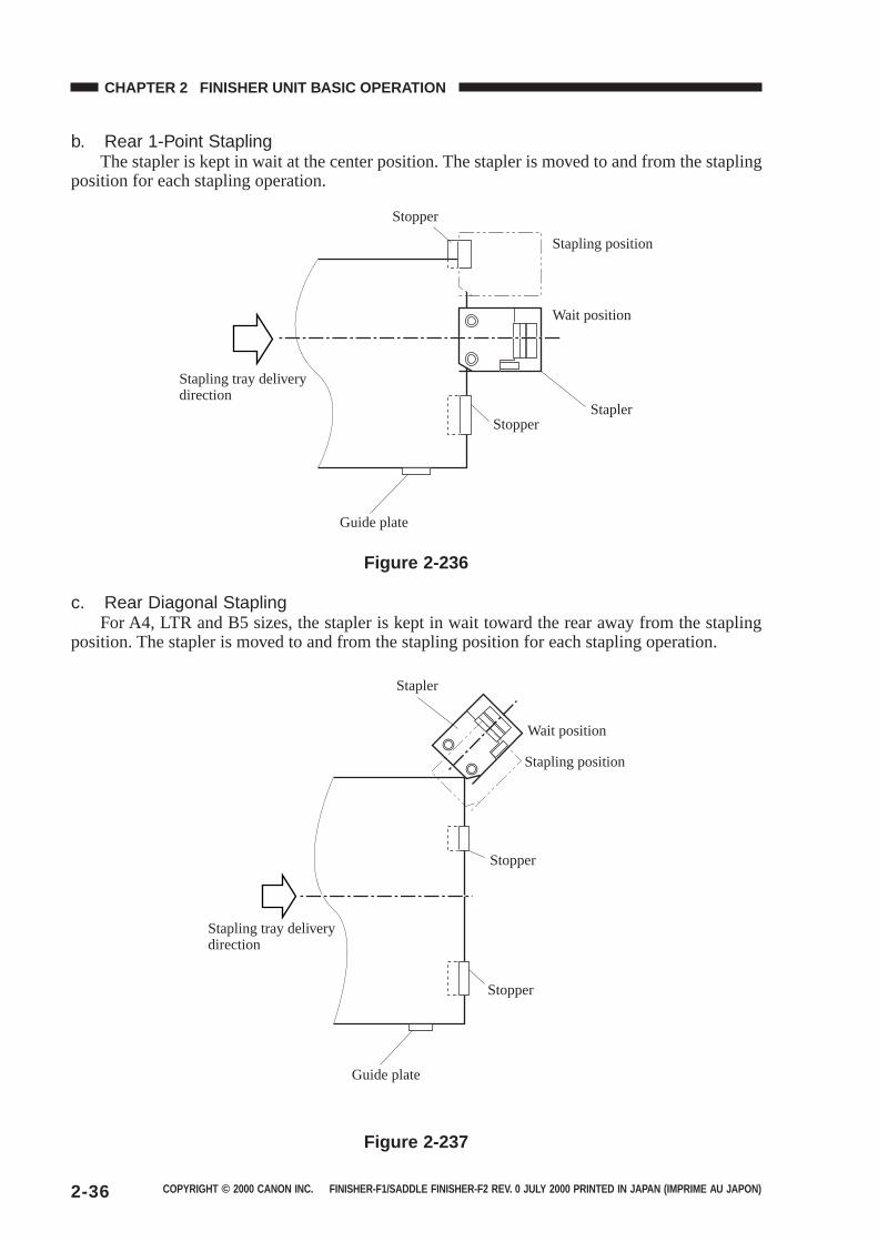
b. Rear 1-Point StaplingThe stapler is kept in wait at the center position. The stapler is moved to and from the stapling
position for each stapling operation.
Stopper
Stapling position
Wait position
StaplerStopper
Guide plate
Stapling tray delivery direction
Figure 2-236
c. Rear Diagonal StaplingFor A4, LTR and B5 sizes, the stapler is kept in wait toward the rear away from the stapling
position. The stapler is moved to and from the stapling position for each stapling operation.
Stapler
Wait position
Stapling position
Stopper
Stopper
Guide plate
Stapling tray delivery direction
Figure 2-237
COPYRIGHT © 2000 CANON INC. FINISHER-F1/SADDLE FINISHER-F2 REV. 0 JULY 2000 PRINTED IN JAPAN (IMPRIME AU JAPON) 2-37
CHAPTER 2 FINISHER UNIT BASIC OPERATION
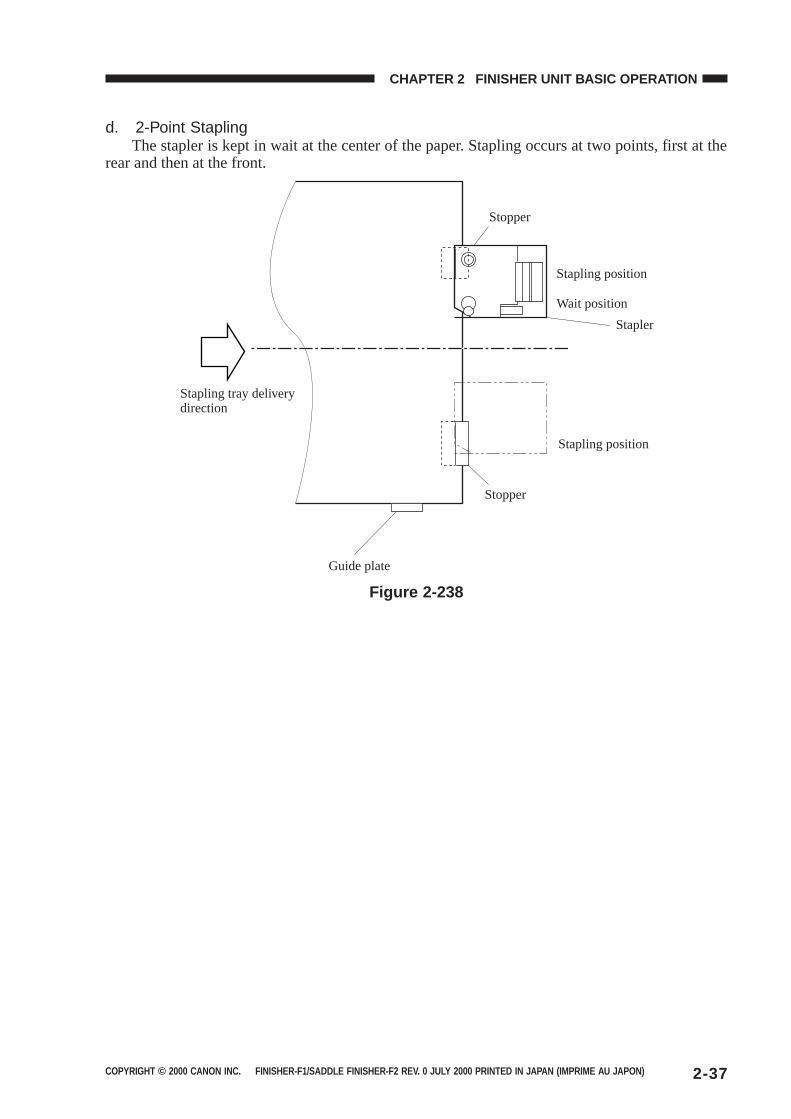
d. 2-Point StaplingThe stapler is kept in wait at the center of the paper. Stapling occurs at two points, first at the
rear and then at the front.
Stapling tray delivery direction
Stopper
Stapling position
Wait position
Stapler
Stapling position
Stopper
Guide plate
Figure 2-238
COPYRIGHT © 2000 CANON INC. FINISHER-F1/SADDLE FINISHER-F2 REV. 0 JULY 2000 PRINTED IN JAPAN (IMPRIME AU JAPON)2-38
CHAPTER 2 FINISHER UNIT BASIC OPERATION
G. Tray Operation
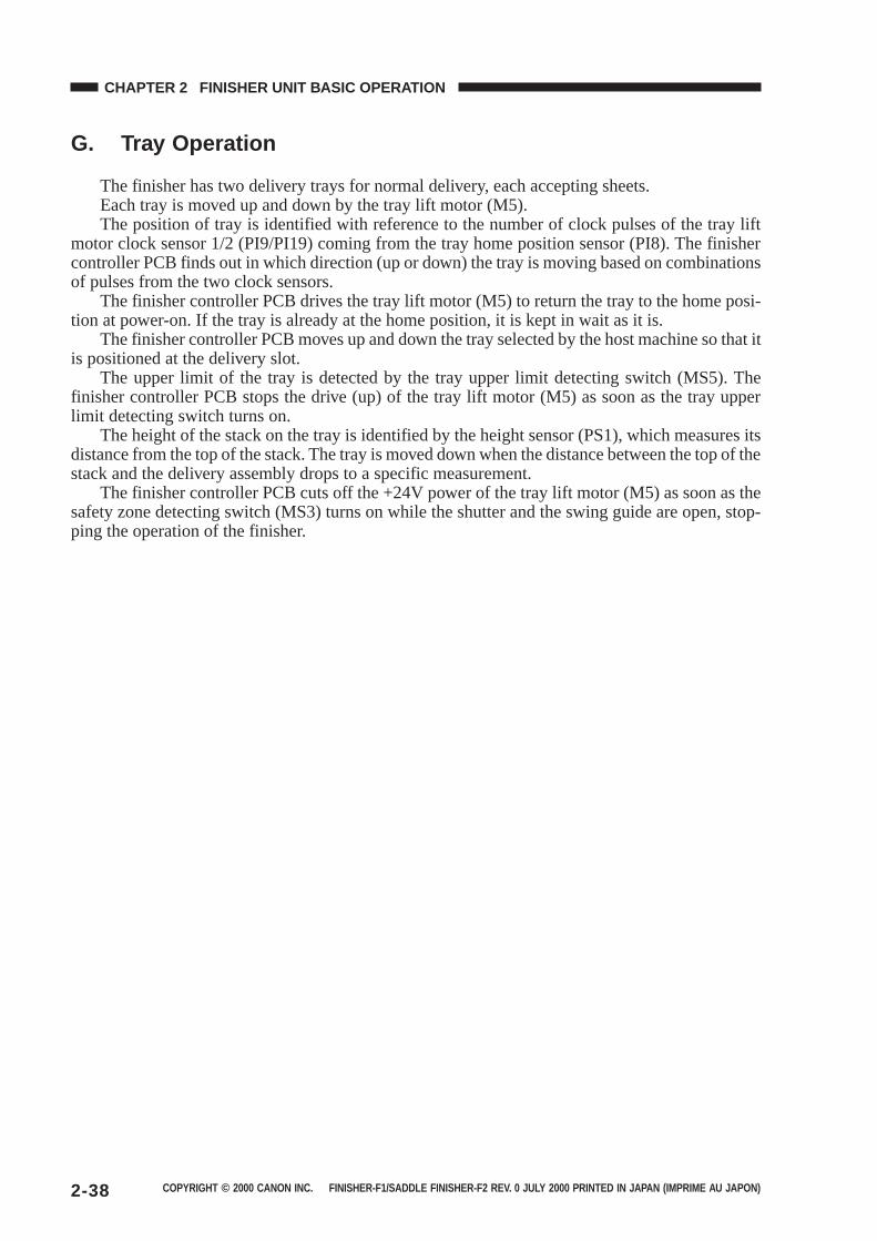
The finisher has two delivery trays for normal delivery, each accepting sheets.Each tray is moved up and down by the tray lift motor (M5).The position of tray is identified with reference to the number of clock pulses of the tray lift
motor clock sensor 1/2 (PI9/PI19) coming from the tray home position sensor (PI8). The finishercontroller PCB finds out in which direction (up or down) the tray is moving based on combinationsof pulses from the two clock sensors.
The finisher controller PCB drives the tray lift motor (M5) to return the tray to the home posi-tion at power-on. If the tray is already at the home position, it is kept in wait as it is.
The finisher controller PCB moves up and down the tray selected by the host machine so that itis positioned at the delivery slot.
The upper limit of the tray is detected by the tray upper limit detecting switch (MS5). Thefinisher controller PCB stops the drive (up) of the tray lift motor (M5) as soon as the tray upperlimit detecting switch turns on.
The height of the stack on the tray is identified by the height sensor (PS1), which measures itsdistance from the top of the stack. The tray is moved down when the distance between the top of thestack and the delivery assembly drops to a specific measurement.
The finisher controller PCB cuts off the +24V power of the tray lift motor (M5) as soon as thesafety zone detecting switch (MS3) turns on while the shutter and the swing guide are open, stop-ping the operation of the finisher.

COPYRIGHT © 2000 CANON INC. FINISHER-F1/SADDLE FINISHER-F2 REV. 0 JULY 2000 PRINTED IN JAPAN (IMPRIME AU JAPON) 2-39
CHAPTER 2 FINISHER UNIT BASIC OPERATION
Tray 1
Tray 2
Tray guide
Tray upper limit detecting switch (MS5)
Encoder
Tray lift motor clock sensor 2 (PI19)
Tray lift motor clock sensor 1 (PI19)
Safety zone switch (MS3)
Tray home position sensor (PI8)Tray lift motor (M5)
Figure 2-239
COPYRIGHT © 2000 CANON INC. FINISHER-F1/SADDLE FINISHER-F2 REV. 0 JULY 2000 PRINTED IN JAPAN (IMPRIME AU JAPON)2-40
CHAPTER 2 FINISHER UNIT BASIC OPERATION
H. Detecting the Height of Stack on the Tray
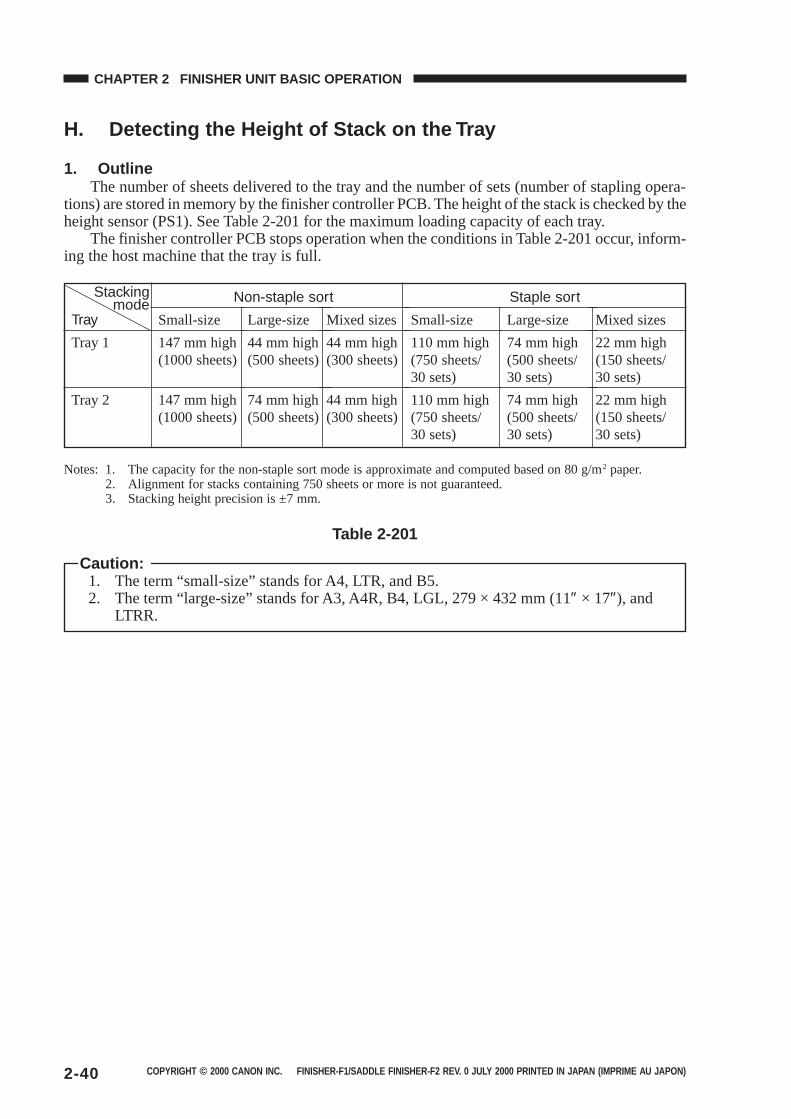
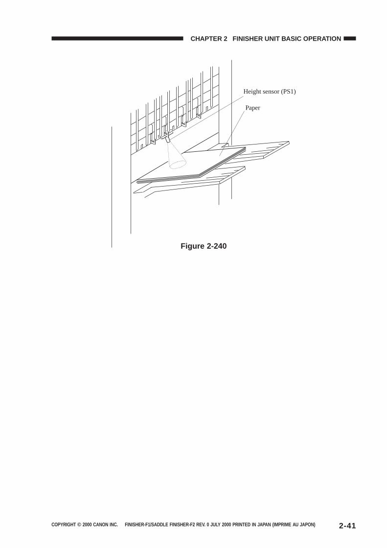
1. OutlineThe number of sheets delivered to the tray and the number of sets (number of stapling opera-
tions) are stored in memory by the finisher controller PCB. The height of the stack is checked by theheight sensor (PS1). See Table 2-201 for the maximum loading capacity of each tray.
The finisher controller PCB stops operation when the conditions in Table 2-201 occur, inform-ing the host machine that the tray is full.
Notes: 1. The capacity for the non-staple sort mode is approximate and computed based on 80 g/m2 paper.2. Alignment for stacks containing 750 sheets or more is not guaranteed.3. Stacking height precision is ±7 mm.
Caution:1. The term “small-size” stands for A4, LTR, and B5.2. The term “large-size” stands for A3, A4R, B4, LGL, 279 × 432 mm (11″ × 17″), and
LTRR.
Table 2-201
Tray
Tray 1
Tray 2
Small-size
147 mm high(1000 sheets)
147 mm high(1000 sheets)
Large-size
44 mm high(500 sheets)
74 mm high(500 sheets)
Small-size
110 mm high(750 sheets/30 sets)
110 mm high(750 sheets/30 sets)
Non-staple sort Staple sort
Mixed sizes
44 mm high(300 sheets)
44 mm high(300 sheets)
Large-size
74 mm high(500 sheets/30 sets)
74 mm high(500 sheets/30 sets)
Mixed sizes
22 mm high(150 sheets/30 sets)
22 mm high(150 sheets/30 sets)
Stackingmode
COPYRIGHT © 2000 CANON INC. FINISHER-F1/SADDLE FINISHER-F2 REV. 0 JULY 2000 PRINTED IN JAPAN (IMPRIME AU JAPON) 2-41
CHAPTER 2 FINISHER UNIT BASIC OPERATION
Height sensor (PS1)
Paper
Figure 2-240
COPYRIGHT © 2000 CANON INC. FINISHER-F1/SADDLE FINISHER-F2 REV. 0 JULY 2000 PRINTED IN JAPAN (IMPRIME AU JAPON)2-42
CHAPTER 2 FINISHER UNIT BASIC OPERATION
I. Shutter Operation
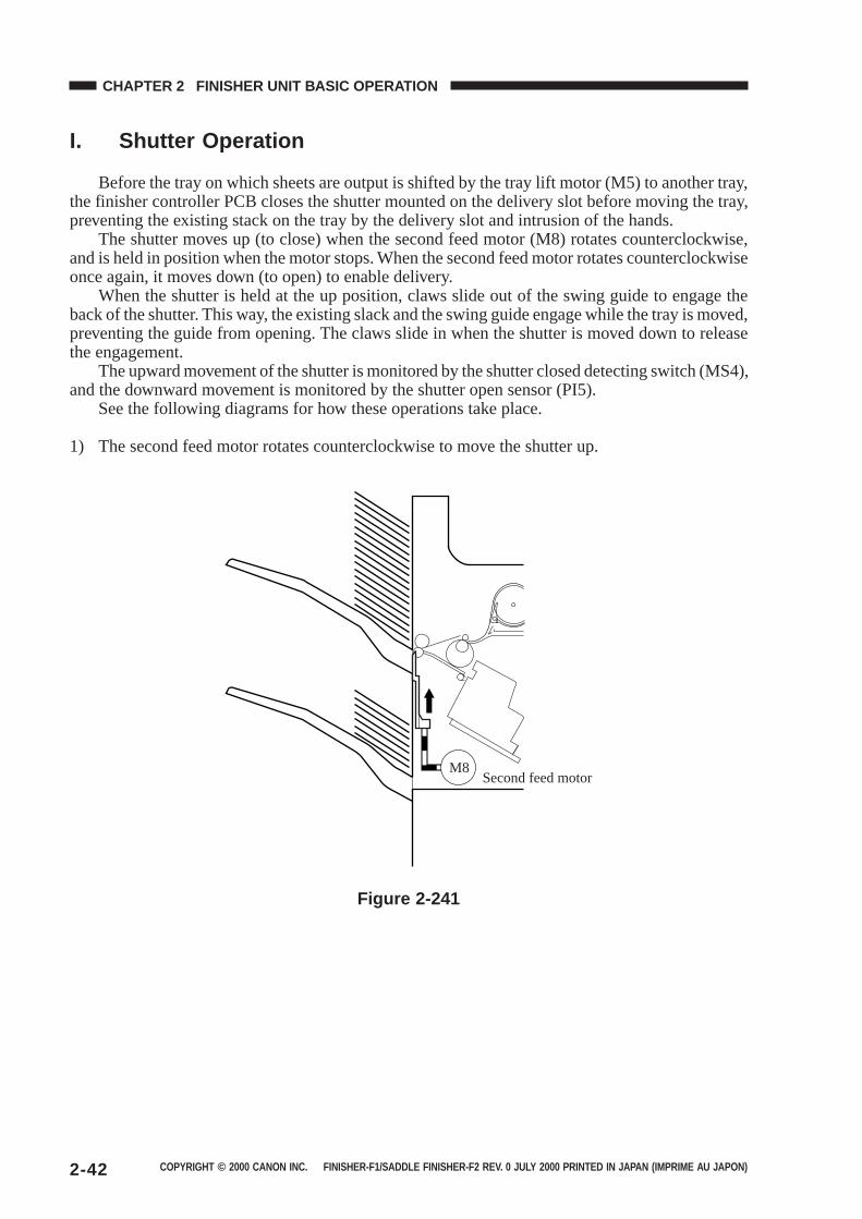
Before the tray on which sheets are output is shifted by the tray lift motor (M5) to another tray,the finisher controller PCB closes the shutter mounted on the delivery slot before moving the tray,preventing the existing stack on the tray by the delivery slot and intrusion of the hands.
The shutter moves up (to close) when the second feed motor (M8) rotates counterclockwise,and is held in position when the motor stops. When the second feed motor rotates counterclockwiseonce again, it moves down (to open) to enable delivery.
When the shutter is held at the up position, claws slide out of the swing guide to engage theback of the shutter. This way, the existing slack and the swing guide engage while the tray is moved,preventing the guide from opening. The claws slide in when the shutter is moved down to releasethe engagement.
The upward movement of the shutter is monitored by the shutter closed detecting switch (MS4),and the downward movement is monitored by the shutter open sensor (PI5).
See the following diagrams for how these operations take place.
1) The second feed motor rotates counterclockwise to move the shutter up.
M8Second feed motor
Figure 2-241
COPYRIGHT © 2000 CANON INC. FINISHER-F1/SADDLE FINISHER-F2 REV. 0 JULY 2000 PRINTED IN JAPAN (IMPRIME AU JAPON) 2-43
CHAPTER 2 FINISHER UNIT BASIC OPERATION
2) The tray lift motor rotates, and the new tray moves to the stacking lower limit. The distance ofmovement is detected by the tray lift motor clock sensor 1/2 (PI9/19).
Tray lift motor
M5
Figure 2-242
3) The second feed motor rotates counterclockwise, and the shutter moves down.
MM8 Second feed motor
Figure 2-243
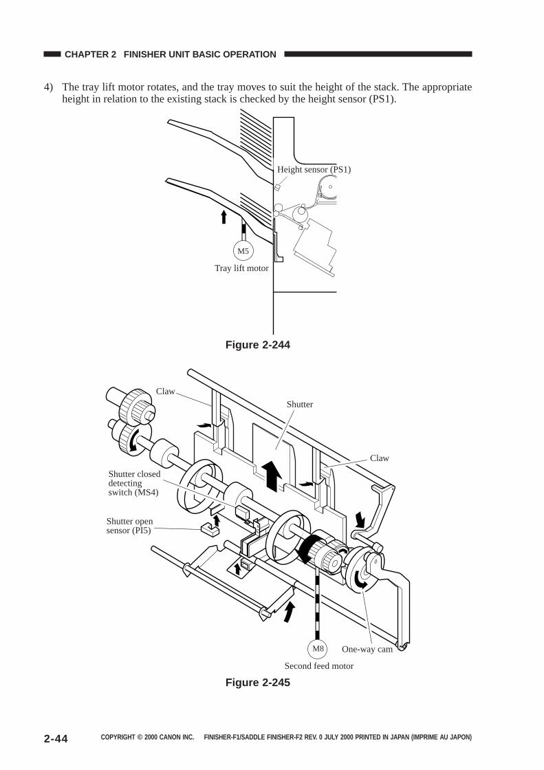
COPYRIGHT © 2000 CANON INC. FINISHER-F1/SADDLE FINISHER-F2 REV. 0 JULY 2000 PRINTED IN JAPAN (IMPRIME AU JAPON)2-44
CHAPTER 2 FINISHER UNIT BASIC OPERATION
4) The tray lift motor rotates, and the tray moves to suit the height of the stack. The appropriateheight in relation to the existing stack is checked by the height sensor (PS1).
Tray lift motor
Height sensor (PS1)
M5
Figure 2-244
M8
Claw
Shutter closed detecting switch (MS4)
Shutter open sensor (PI5)
Shutter
Claw
One-way cam
Second feed motor
Figure 2-245
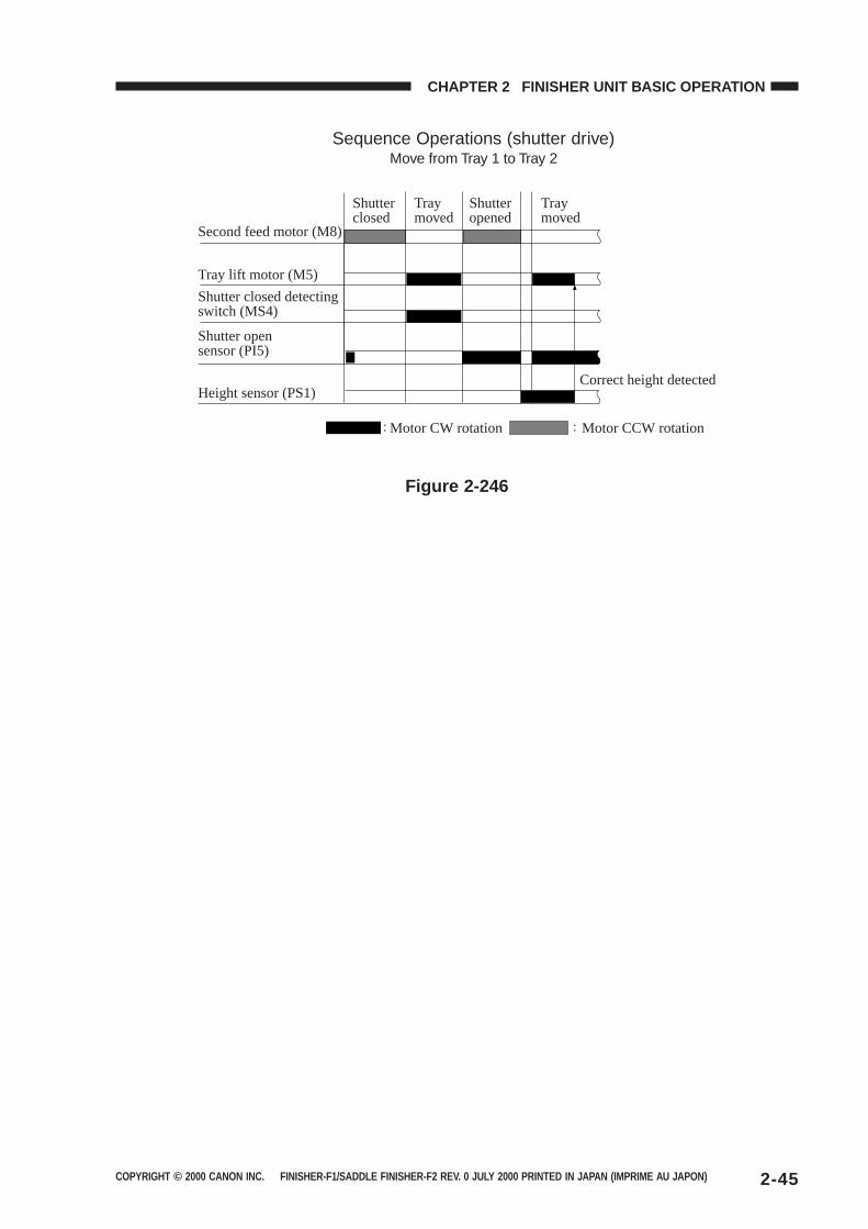
COPYRIGHT © 2000 CANON INC. FINISHER-F1/SADDLE FINISHER-F2 REV. 0 JULY 2000 PRINTED IN JAPAN (IMPRIME AU JAPON) 2-45
CHAPTER 2 FINISHER UNIT BASIC OPERATION
Sequence Operations (shutter drive)Move from Tray 1 to Tray 2
Second feed motor (M8)
Shutter closed
Tray moved
Shutter opened
Tray moved
Tray lift motor (M5)
Shutter closed detecting switch (MS4)
Shutter open sensor (PI5)
Height sensor (PS1)Correct height detected
Motor CW rotation Motor CCW rotation
Figure 2-246
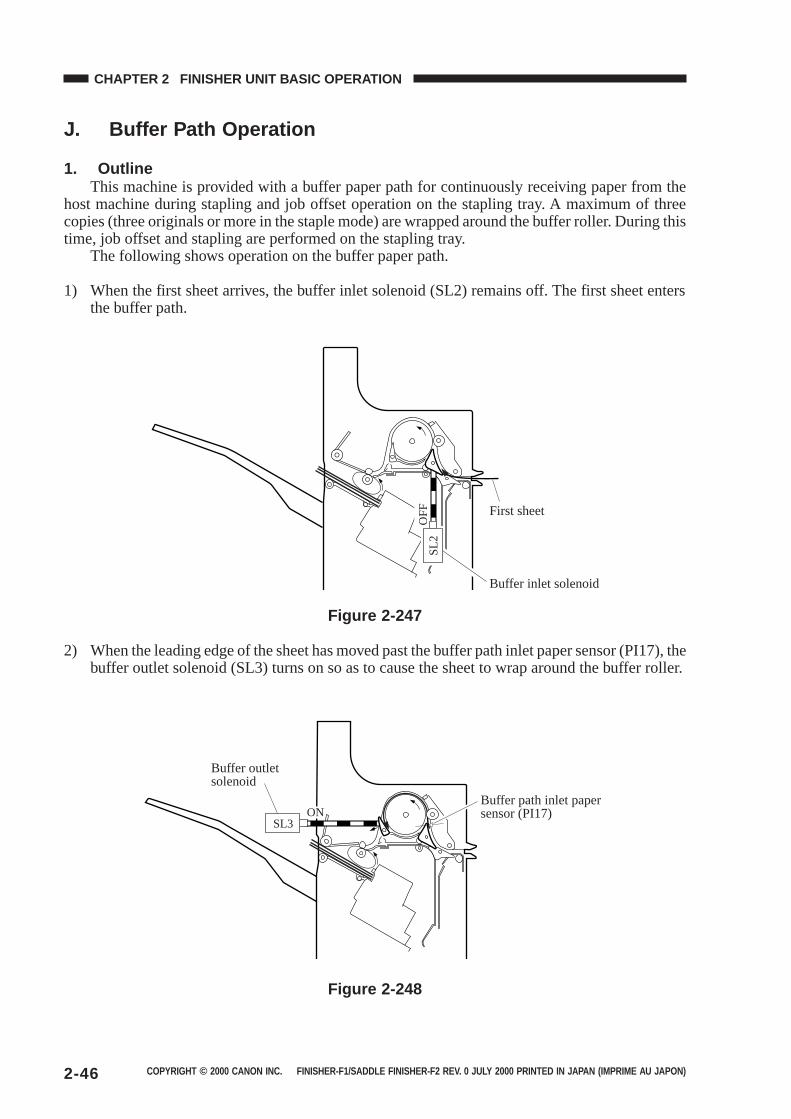
COPYRIGHT © 2000 CANON INC. FINISHER-F1/SADDLE FINISHER-F2 REV. 0 JULY 2000 PRINTED IN JAPAN (IMPRIME AU JAPON)2-46
CHAPTER 2 FINISHER UNIT BASIC OPERATION
J. Buffer Path Operation
1. OutlineThis machine is provided with a buffer paper path for continuously receiving paper from the
host machine during stapling and job offset operation on the stapling tray. A maximum of threecopies (three originals or more in the staple mode) are wrapped around the buffer roller. During thistime, job offset and stapling are performed on the stapling tray.
The following shows operation on the buffer paper path.
1) When the first sheet arrives, the buffer inlet solenoid (SL2) remains off. The first sheet entersthe buffer path.
OF
FS
L2
First sheet
Buffer inlet solenoid
Figure 2-247
2) When the leading edge of the sheet has moved past the buffer path inlet paper sensor (PI17), thebuffer outlet solenoid (SL3) turns on so as to cause the sheet to wrap around the buffer roller.
ONSL3
Buffer outlet solenoid
Buffer path inlet paper sensor (PI17)
Figure 2-248
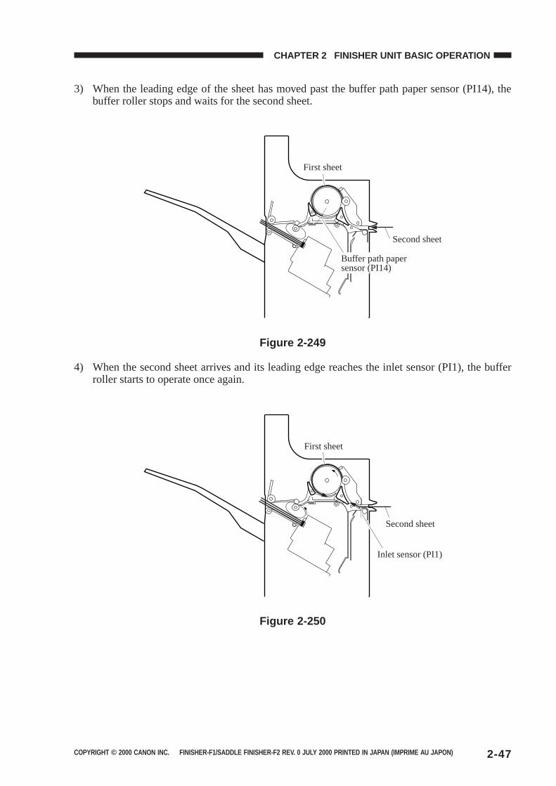
COPYRIGHT © 2000 CANON INC. FINISHER-F1/SADDLE FINISHER-F2 REV. 0 JULY 2000 PRINTED IN JAPAN (IMPRIME AU JAPON) 2-47
CHAPTER 2 FINISHER UNIT BASIC OPERATION
3) When the leading edge of the sheet has moved past the buffer path paper sensor (PI14), thebuffer roller stops and waits for the second sheet.
First sheet
Second sheet
Buffer path paper sensor (PI14)
Figure 2-249
4) When the second sheet arrives and its leading edge reaches the inlet sensor (PI1), the bufferroller starts to operate once again.
Second sheet
Inlet sensor (PI1)
First sheet
Figure 2-250
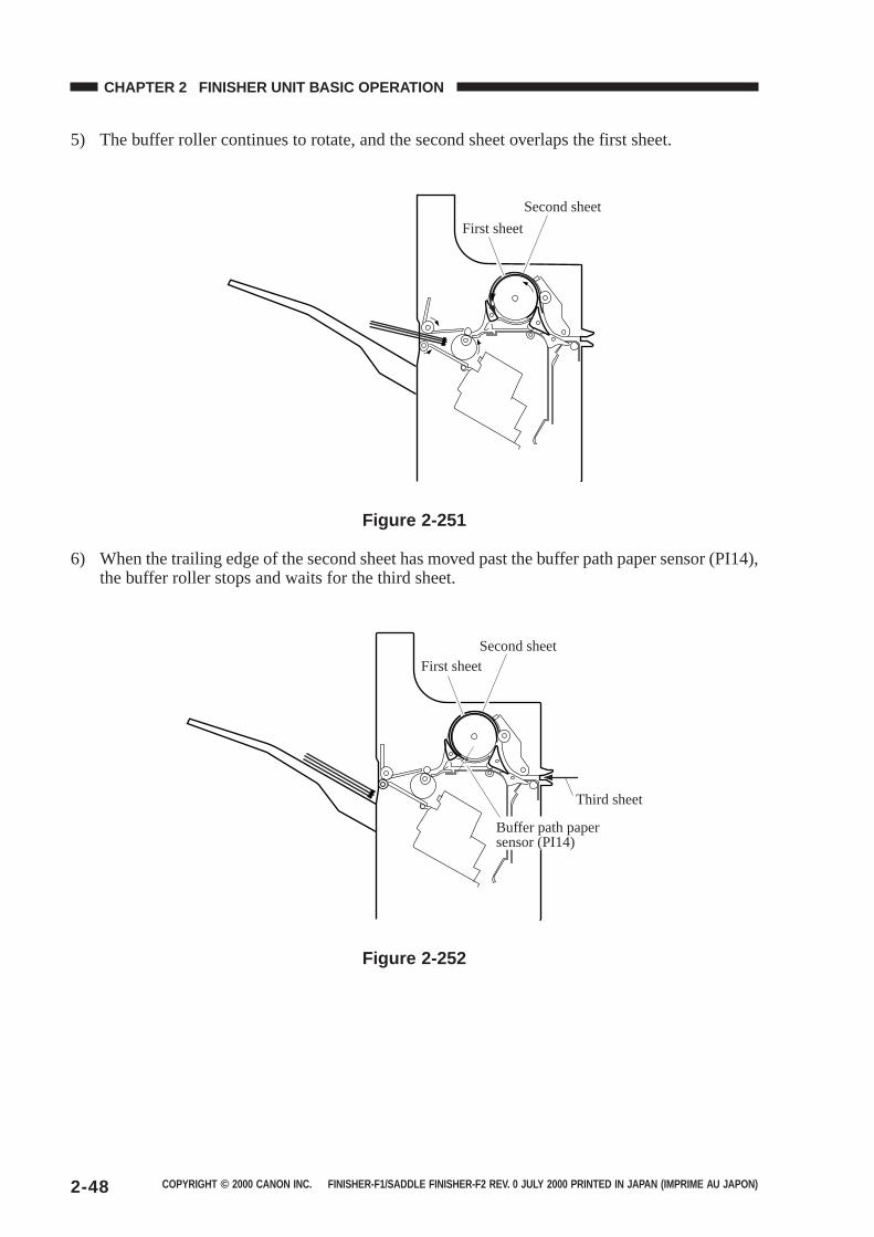
COPYRIGHT © 2000 CANON INC. FINISHER-F1/SADDLE FINISHER-F2 REV. 0 JULY 2000 PRINTED IN JAPAN (IMPRIME AU JAPON)2-48
CHAPTER 2 FINISHER UNIT BASIC OPERATION
5) The buffer roller continues to rotate, and the second sheet overlaps the first sheet.
First sheet
Second sheet
Figure 2-251
6) When the trailing edge of the second sheet has moved past the buffer path paper sensor (PI14),the buffer roller stops and waits for the third sheet.
First sheetSecond sheet
Third sheet
Buffer path paper sensor (PI14)
Figure 2-252
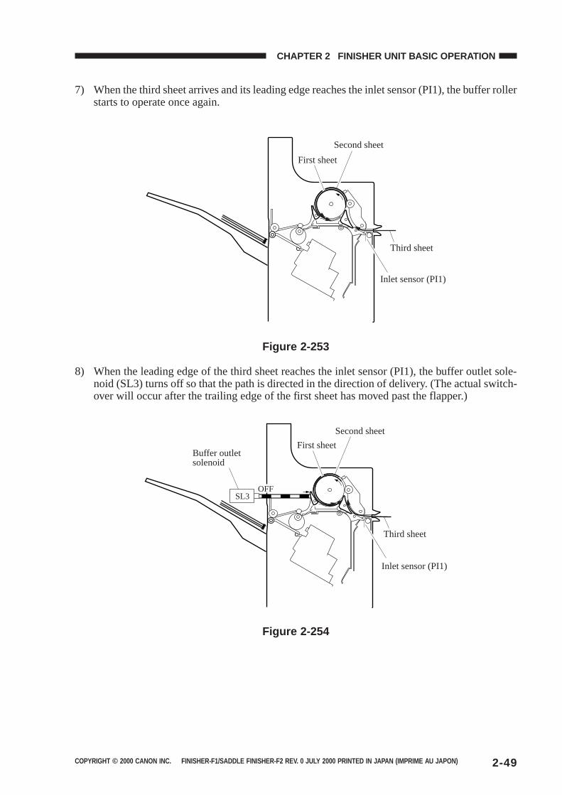
COPYRIGHT © 2000 CANON INC. FINISHER-F1/SADDLE FINISHER-F2 REV. 0 JULY 2000 PRINTED IN JAPAN (IMPRIME AU JAPON) 2-49
CHAPTER 2 FINISHER UNIT BASIC OPERATION
7) When the third sheet arrives and its leading edge reaches the inlet sensor (PI1), the buffer rollerstarts to operate once again.
First sheet
Second sheet
Third sheet
Inlet sensor (PI1)
Figure 2-253
8) When the leading edge of the third sheet reaches the inlet sensor (PI1), the buffer outlet sole-noid (SL3) turns off so that the path is directed in the direction of delivery. (The actual switch-over will occur after the trailing edge of the first sheet has moved past the flapper.)
OFFSL3
Buffer outlet solenoid
First sheet
Second sheet
Third sheet
Inlet sensor (PI1)
Figure 2-254
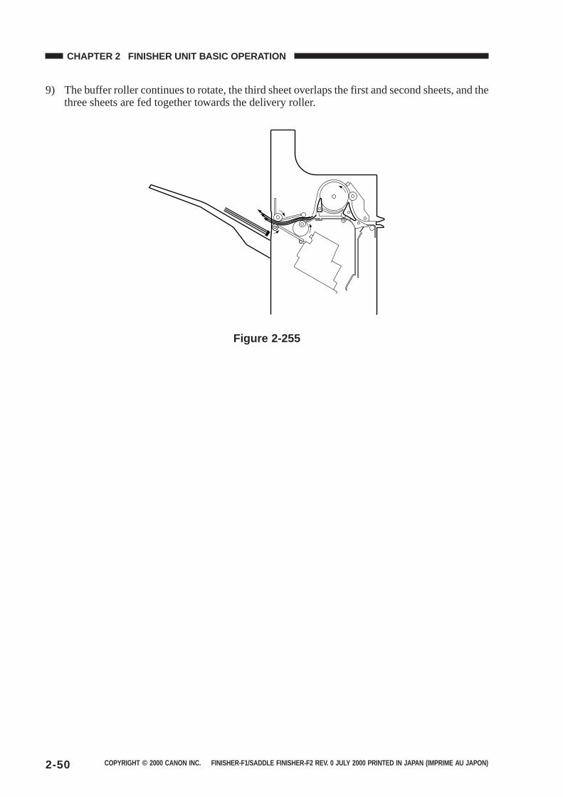
COPYRIGHT © 2000 CANON INC. FINISHER-F1/SADDLE FINISHER-F2 REV. 0 JULY 2000 PRINTED IN JAPAN (IMPRIME AU JAPON)2-50
CHAPTER 2 FINISHER UNIT BASIC OPERATION
9) The buffer roller continues to rotate, the third sheet overlaps the first and second sheets, and thethree sheets are fed together towards the delivery roller.
Figure 2-255
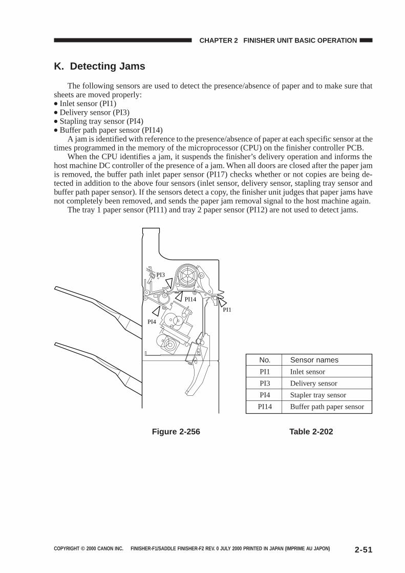
COPYRIGHT © 2000 CANON INC. FINISHER-F1/SADDLE FINISHER-F2 REV. 0 JULY 2000 PRINTED IN JAPAN (IMPRIME AU JAPON) 2-51
CHAPTER 2 FINISHER UNIT BASIC OPERATION
K. Detecting Jams
The following sensors are used to detect the presence/absence of paper and to make sure thatsheets are moved properly:● Inlet sensor (PI1)● Delivery sensor (PI3)● Stapling tray sensor (PI4)● Buffer path paper sensor (PI14)
A jam is identified with reference to the presence/absence of paper at each specific sensor at thetimes programmed in the memory of the microprocessor (CPU) on the finisher controller PCB.
When the CPU identifies a jam, it suspends the finisher’s delivery operation and informs thehost machine DC controller of the presence of a jam. When all doors are closed after the paper jamis removed, the buffer path inlet paper sensor (PI17) checks whether or not copies are being de-tected in addition to the above four sensors (inlet sensor, delivery sensor, stapling tray sensor andbuffer path paper sensor). If the sensors detect a copy, the finisher unit judges that paper jams havenot completely been removed, and sends the paper jam removal signal to the host machine again.
The tray 1 paper sensor (PI11) and tray 2 paper sensor (PI12) are not used to detect jams.
PI1
PI14
PI4
PI3
Figure 2-256 Table 2-202
No. Sensor names
PI1 Inlet sensor
PI3 Delivery sensor
PI4 Stapler tray sensor
PI14 Buffer path paper sensor
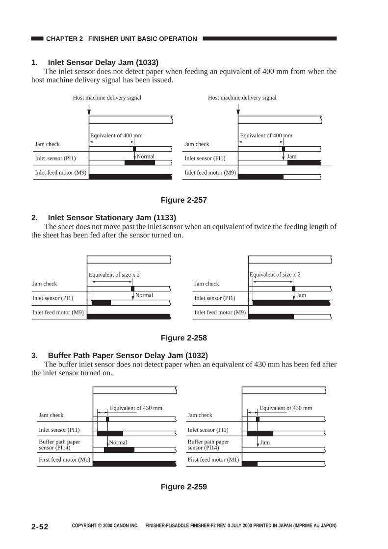
COPYRIGHT © 2000 CANON INC. FINISHER-F1/SADDLE FINISHER-F2 REV. 0 JULY 2000 PRINTED IN JAPAN (IMPRIME AU JAPON)2-52
CHAPTER 2 FINISHER UNIT BASIC OPERATION
1. Inlet Sensor Delay Jam (1033)The inlet sensor does not detect paper when feeding an equivalent of 400 mm from when the
host machine delivery signal has been issued.
Host machine delivery signal Host machine delivery signal
Jam check
Equivalent of 400 mm
Inlet sensor (PI1) Normal
Inlet feed motor (M9)
Jam check
Inlet sensor (PI1)
Inlet feed motor (M9)
Jam
Equivalent of 400 mm
Figure 2-257
2. Inlet Sensor Stationary Jam (1133)The sheet does not move past the inlet sensor when an equivalent of twice the feeding length of
the sheet has been fed after the sensor turned on.
Jam check
Equivalent of size x 2
Inlet sensor (PI1) Normal
Inlet feed motor (M9)
Jam check
Equivalent of size x 2
Inlet sensor (PI1) Jam
Inlet feed motor (M9)
Figure 2-258
3. Buffer Path Paper Sensor Delay Jam (1032)The buffer inlet sensor does not detect paper when an equivalent of 430 mm has been fed after
the inlet sensor turned on.
Jam checkEquivalent of 430 mmEquivalent of 430 mm
Inlet sensor (PI1)
Buffer path paper sensor (PI14)
Normal
First feed motor (M1)
Jam check
Inlet sensor (PI1)
Buffer path paper sensor (PI14)
First feed motor (M1)
Jam
Figure 2-259
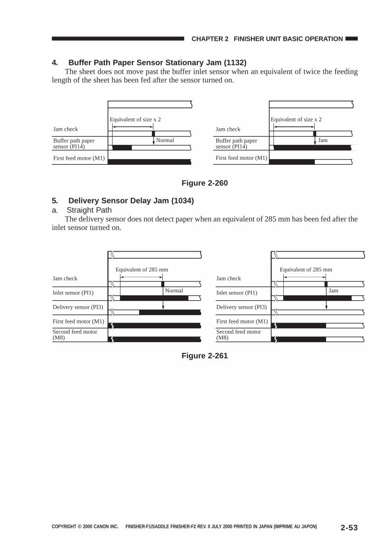
COPYRIGHT © 2000 CANON INC. FINISHER-F1/SADDLE FINISHER-F2 REV. 0 JULY 2000 PRINTED IN JAPAN (IMPRIME AU JAPON) 2-53
CHAPTER 2 FINISHER UNIT BASIC OPERATION
4. Buffer Path Paper Sensor Stationary Jam (1132)The sheet does not move past the buffer inlet sensor when an equivalent of twice the feeding
length of the sheet has been fed after the sensor turned on.
Jam check
Equivalent of size x 2
Buffer path paper sensor (PI14)
Normal
First feed motor (M1)
Jam check
Equivalent of size x 2
Buffer path paper sensor (PI14)
Jam
First feed motor (M1)
Figure 2-260
5. Delivery Sensor Delay Jam (1034)a. Straight Path
The delivery sensor does not detect paper when an equivalent of 285 mm has been fed after theinlet sensor turned on.
Jam check
Equivalent of 285 mm
Inlet sensor (PI1) Normal
Delivery sensor (PI3)
First feed motor (M1)
Second feed motor (M8)
Jam check
Inlet sensor (PI1)
Delivery sensor (PI3)
First feed motor (M1)
Second feed motor (M8)
Equivalent of 285 mm
Jam
Figure 2-261
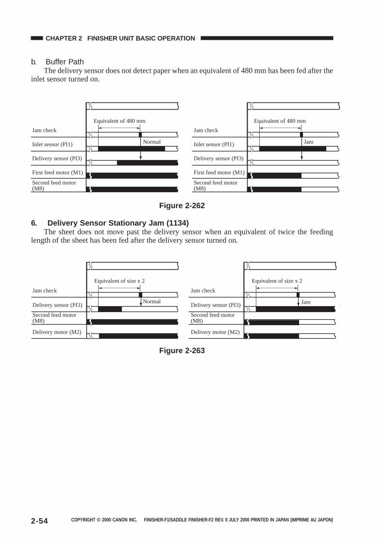
COPYRIGHT © 2000 CANON INC. FINISHER-F1/SADDLE FINISHER-F2 REV. 0 JULY 2000 PRINTED IN JAPAN (IMPRIME AU JAPON)2-54
CHAPTER 2 FINISHER UNIT BASIC OPERATION
b. Buffer PathThe delivery sensor does not detect paper when an equivalent of 480 mm has been fed after the
inlet sensor turned on.
Jam check
Equivalent of 480 mm Equivalent of 480 mm
Inlet sensor (PI1) Normal
Delivery sensor (PI3)
First feed motor (M1)
Second feed motor (M8)
Jam check
Inlet sensor (PI1)
Delivery sensor (PI3)
First feed motor (M1)
Second feed motor (M8)
Jam
Figure 2-262
6. Delivery Sensor Stationary Jam (1134)The sheet does not move past the delivery sensor when an equivalent of twice the feeding
length of the sheet has been fed after the delivery sensor turned on.
Jam check
Equivalent of size x 2 Equivalent of size x 2
Delivery sensor (PI3)Normal
Second feed motor (M8)
Delivery motor (M2)
Jam check
Delivery sensor (PI3)
Second feed motor (M8)
Delivery motor (M2)
Jam
Figure 2-263
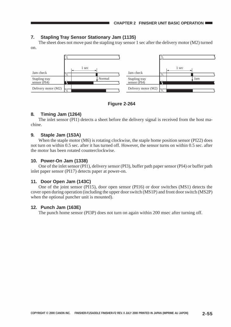
COPYRIGHT © 2000 CANON INC. FINISHER-F1/SADDLE FINISHER-F2 REV. 0 JULY 2000 PRINTED IN JAPAN (IMPRIME AU JAPON) 2-55
CHAPTER 2 FINISHER UNIT BASIC OPERATION
7. Stapling Tray Sensor Stationary Jam (1135)The sheet does not move past the stapling tray sensor 1 sec after the delivery motor (M2) turned
on.
Jam check
1 sec 1 sec
Stapling tray sensor (PI4)
Normal
Delivery motor (M2)
Jam check
Stapling tray sensor (PI4)
Delivery motor (M2)
Jam
Figure 2-264
8. Timing Jam (1264)The inlet sensor (PI1) detects a sheet before the delivery signal is received from the host ma-
chine.
9. Staple Jam (153A)When the staple motor (M6) is rotating clockwise, the staple home position sensor (PI22) does
not turn on within 0.5 sec. after it has turned off. However, the sensor turns on within 0.5 sec. afterthe motor has been rotated counterclockwise.
10. Power-On Jam (1338)One of the inlet sensor (PI1), delivery sensor (PI3), buffer path paper sensor (PI4) or buffer path
inlet paper sensor (PI17) detects paper at power-on.
11. Door Open Jam (143C)One of the joint sensor (PI15), door open sensor (PI16) or door switches (MS1) detects the
cover open during operation (including the upper door switch (MS1P) and front door switch (MS2P)when the optional puncher unit is mounted).
12. Punch Jam (163E)The punch home sensor (PI3P) does not turn on again within 200 msec after turning off.
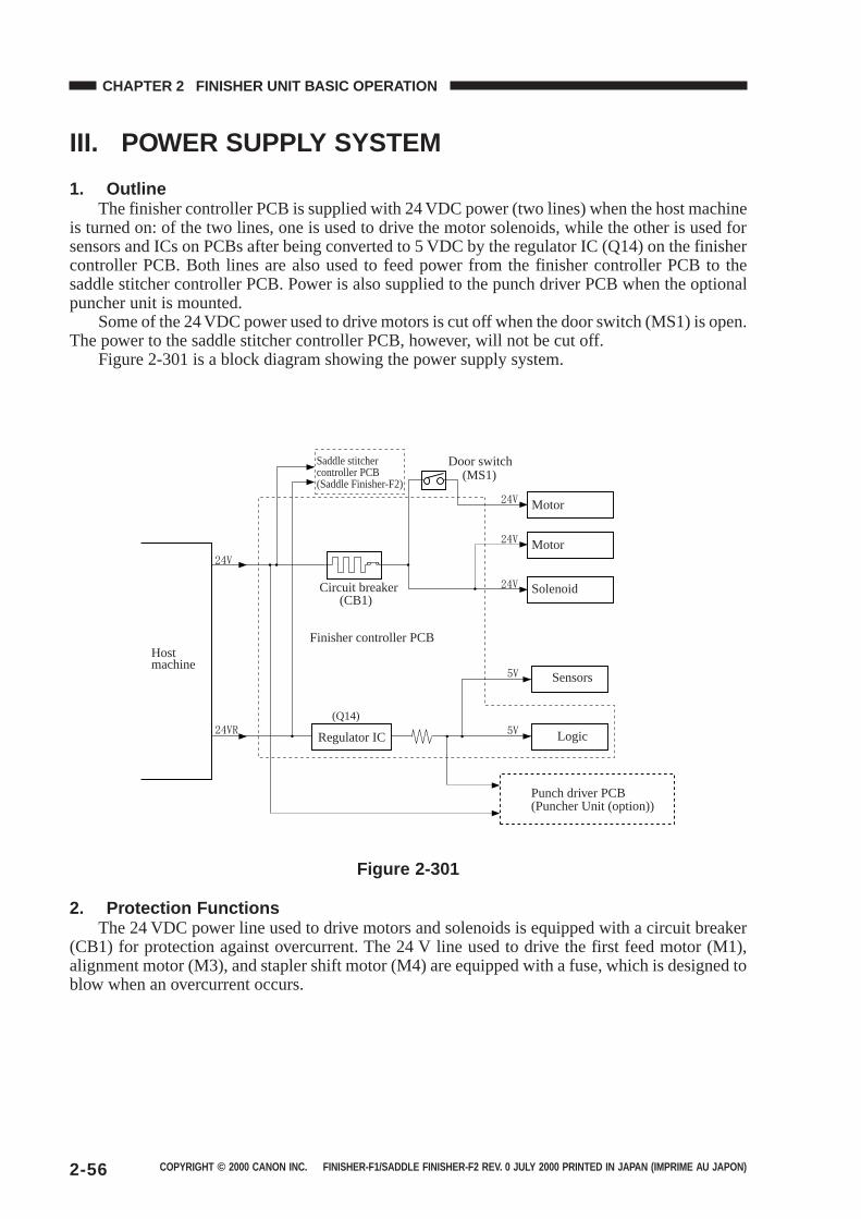
COPYRIGHT © 2000 CANON INC. FINISHER-F1/SADDLE FINISHER-F2 REV. 0 JULY 2000 PRINTED IN JAPAN (IMPRIME AU JAPON)2-56
CHAPTER 2 FINISHER UNIT BASIC OPERATION
III. POWER SUPPLY SYSTEM
1. OutlineThe finisher controller PCB is supplied with 24 VDC power (two lines) when the host machine
is turned on: of the two lines, one is used to drive the motor solenoids, while the other is used forsensors and ICs on PCBs after being converted to 5 VDC by the regulator IC (Q14) on the finishercontroller PCB. Both lines are also used to feed power from the finisher controller PCB to thesaddle stitcher controller PCB. Power is also supplied to the punch driver PCB when the optionalpuncher unit is mounted.
Some of the 24 VDC power used to drive motors is cut off when the door switch (MS1) is open.The power to the saddle stitcher controller PCB, however, will not be cut off.
Figure 2-301 is a block diagram showing the power supply system.
(Q14)
Saddle stitcher controller PCB (Saddle Finisher-F2)
Door switch
Circuit breaker
Motor
Motor
Solenoid
Host machine
Finisher controller PCB
Regulator IC
Sensors
Logic
Punch driver PCB(Puncher Unit (option))
(CB1)
(MS1)
Figure 2-301
2. Protection FunctionsThe 24 VDC power line used to drive motors and solenoids is equipped with a circuit breaker
(CB1) for protection against overcurrent. The 24 V line used to drive the first feed motor (M1),alignment motor (M3), and stapler shift motor (M4) are equipped with a fuse, which is designed toblow when an overcurrent occurs.
COPYRIGHT © 2000 CANON INC. FINISHER-C1/SADDLE FINISHER-C2 REV. 0 JULY 2000 PRINTED IN JAPAN (IMPRIME AU JAPON)
CHAPTER 3
SADDLE STITCHER UNITBASIC OPERATION
I. BASIC OPERATION...................3-1A. Outline ..................................3-1B. Electrical Circuitry ................3-2C. Inputs to and Outputs from the
Saddle Stitcher ControllerPCB ......................................3-3
II. FEEDING/DRIVE SYSTEM .......3-8A. Outline ..................................3-8
III. PAPER OUTPUTMECHANISM .......................... 3-14A. Outline ............................... 3-14B. Controlling the Inlet
Flappers ............................ 3-17
C. Controlling the Movement ofSheets ............................... 3-21
D. Aligning the Sheets ........... 3-23E. Controlling the Phase of the
Crescent Roller.................. 3-26IV. STITCHING SYSTEM ............. 3-28V. FOLDING/DELIVERY
SYSTEM.................................. 3-31VI. CHECKING FOR A JAM ......... 3-38
VII. POWER SUPPLY .................... 3-43
1. This chapter discusses the purpose and role of each of the stitcher’s functions, and the prin-ciples of operation used for the stitcher mechanical and electrical systems. It also explains thetiming at which these systems are operated.
The symbol in drawings indicates transmission of mechanical drive, and signals markedby together with the signal name indicates the flow of electrical signals.
2. In descriptions of digital circuits on the stitcher, “1” indicates a high signal voltage level, while“0” indicates a low signal voltage level. Voltage values differ according to circuit.
A microprocessor is used on the stitcher. A description of microprocessor operation is omittedin this chapter as it is practically impossible to check internal operation of the microprocessor.
Descriptions in this chapter also assume that PCBs will not be repaired at user sites. For thisreason, descriptions of circuits on PCBs is limited to block diagrams. Two types of block dia-grams are provided for separate functions: diagrams indicating details from sensors up to inputsections of major PCBs, and diagrams indicating details from the output sections of majorPCBs up the loads.

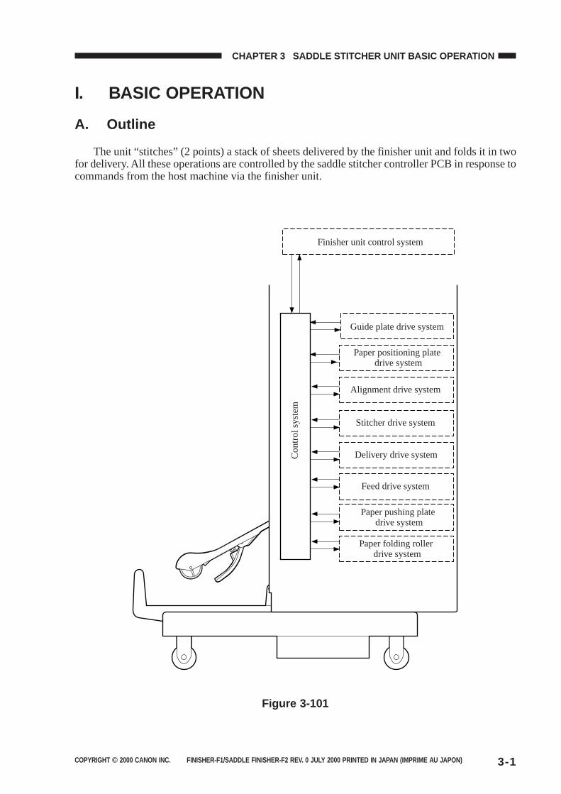
COPYRIGHT © 2000 CANON INC. FINISHER-F1/SADDLE FINISHER-F2 REV. 0 JULY 2000 PRINTED IN JAPAN (IMPRIME AU JAPON) 3-1
CHAPTER 3 SADDLE STITCHER UNIT BASIC OPERATION
I. BASIC OPERATION
A. Outline
The unit “stitches” (2 points) a stack of sheets delivered by the finisher unit and folds it in twofor delivery. All these operations are controlled by the saddle stitcher controller PCB in response tocommands from the host machine via the finisher unit.
Finisher unit control system
Con
trol
sys
tem
Guide plate drive system
Paper positioning plate drive system
Alignment drive system
Stitcher drive system
Delivery drive system
Feed drive system
Paper pushing plate drive system
Paper folding roller drive system
Figure 3-101
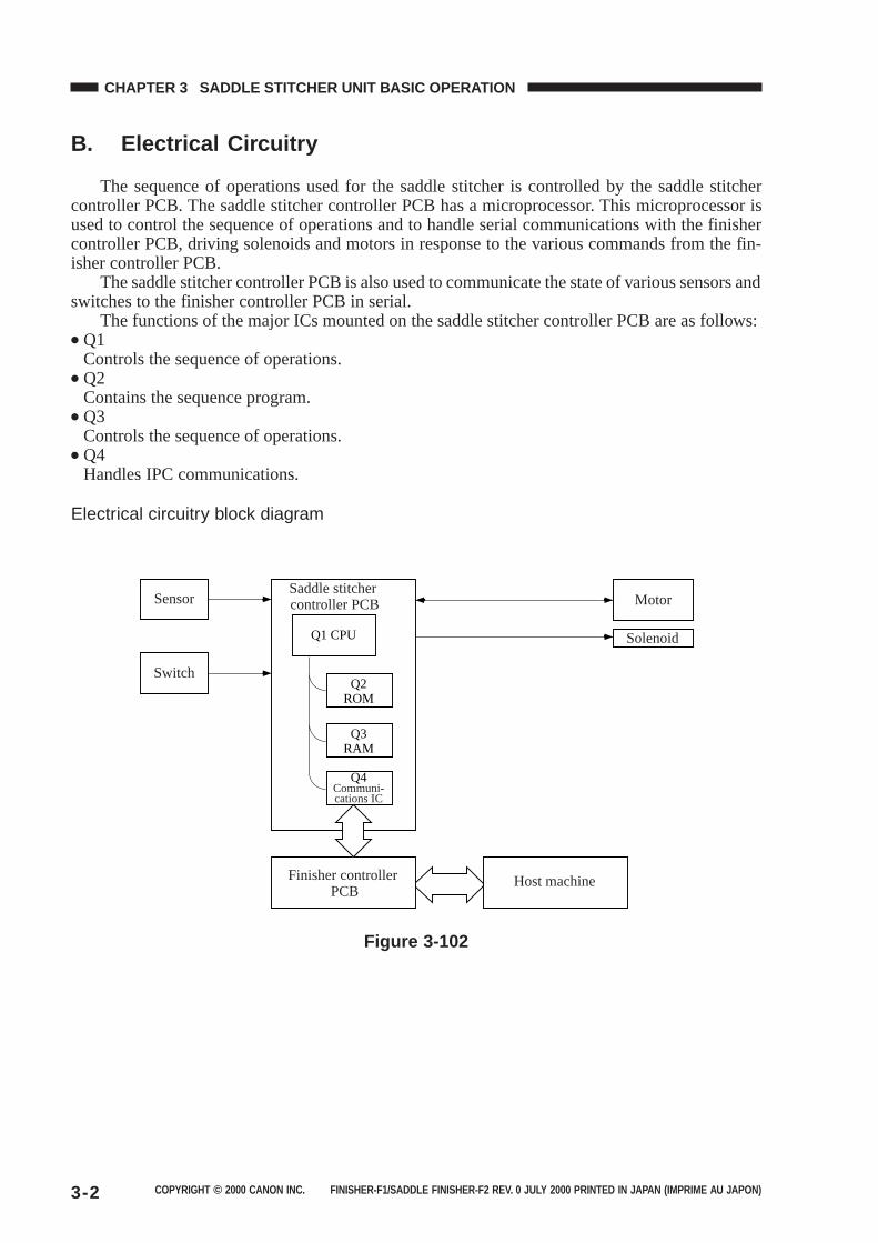
COPYRIGHT © 2000 CANON INC. FINISHER-F1/SADDLE FINISHER-F2 REV. 0 JULY 2000 PRINTED IN JAPAN (IMPRIME AU JAPON)3-2
CHAPTER 3 SADDLE STITCHER UNIT BASIC OPERATION
B. Electrical Circuitry
The sequence of operations used for the saddle stitcher is controlled by the saddle stitchercontroller PCB. The saddle stitcher controller PCB has a microprocessor. This microprocessor isused to control the sequence of operations and to handle serial communications with the finishercontroller PCB, driving solenoids and motors in response to the various commands from the fin-isher controller PCB.
The saddle stitcher controller PCB is also used to communicate the state of various sensors andswitches to the finisher controller PCB in serial.
The functions of the major ICs mounted on the saddle stitcher controller PCB are as follows:● Q1
Controls the sequence of operations.● Q2
Contains the sequence program.● Q3
Controls the sequence of operations.● Q4
Handles IPC communications.
Electrical circuitry block diagram
Sensor
Switch
Q1 CPU
Q2ROM
Q3RAM
Q4Communi-cations IC
Saddle stitcher controller PCB Motor
Solenoid
Host machineFinisher controller PCB
Figure 3-102
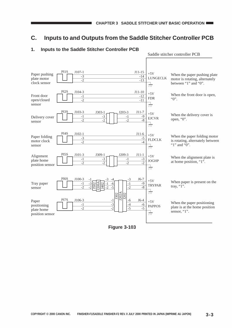
COPYRIGHT © 2000 CANON INC. FINISHER-F1/SADDLE FINISHER-F2 REV. 0 JULY 2000 PRINTED IN JAPAN (IMPRIME AU JAPON) 3-3
CHAPTER 3 SADDLE STITCHER UNIT BASIC OPERATION
C. Inputs to and Outputs from the Saddle Stitcher Controller PCB
1. Inputs to the Saddle Stitcher Controller PCB
Paper folding motor clock sensor
Alignment plate home position sensor
Paper positioning plate home position sensor
Tray paper sensor
PI7S
J209
AJ4
02
J502
J106-3-1-2
PI6S J100-3-1-2
J6-7-9-8
J6-4-6-5
-3-1
-2-1-3
-2
J202
AJ3
02
J202
-6-4
-5-1-3
-2
-3-1
-2-4-6
-5
PI5S J101-3-1-2
J11-1-3-2
PI4S J102-1-3-2
J11-6-5-4
PI3S J103-3-1-2
J11-7-9-8
-3J303-1
-2-1
J203-3
-2
-3J309-1
-2-1
J209-3
-2
PI2S J104-3-1-2
J11-10-12-11
PI1S J107-1-3-2
J11-15
Saddle stitcher controller PCB
When the paper pushing plate motor is rotating, alternately between “1” and “0”.
+5VLUNGECLK
When the front door is open, “0”.
+5VFDR
When the paper folding motor is rotating, alternately between “1” and “0”.
+5VFLDCLK
When the alignment plate is at home position, “1”.
+5VJOGHP
When paper is present on the tray, “1”.
+5VTRYPAR
When the paper positioning plate is at the home position sensor, “1”.
+5VPAPPOS
When the delivery cover is open, “0”.
+5VEJCVR
-14-13
Paper pushing plate motor clock sensor
Front door open/closed sensor
Delivery cover sensor
Figure 3-103
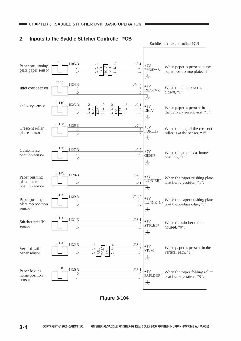
COPYRIGHT © 2000 CANON INC. FINISHER-F1/SADDLE FINISHER-F2 REV. 0 JULY 2000 PRINTED IN JAPAN (IMPRIME AU JAPON)3-4
CHAPTER 3 SADDLE STITCHER UNIT BASIC OPERATION
2. Inputs to the Saddle Stitcher Controller PCB
PI8S J105-3-1-2
-1-3-2
-3-1-2
J6-1 +5V When paper is present at the paper positioning plate, “1”.PPOSPAR-3
-2J201
AJ3
01
J201
PI9S J124-3-1-2
J10-6 +5V When the inlet cover is closed, “1”. INLTCVR-8
-7
PI11S J525-3-1-2
-2-4-3
-3-1-2
J9-1 +5V When paper is present in the delivery sensor unit, “1”. DELV-3
-2J425
J325
-2-4-3
-3-1-2J2
25J1
25PI12S J126-3
-1-2
J9-4 +5V When the flag of the crescent roller is at the sensor, “1”.FDRLHP-6
-5
PI13S J127-3-1-2
J9-7 +5V When the guide is at home position, “1”.GIDHP-9
-8
PI14S J128-3-1-2
J9-10 +5V When the paper pushing plate is at home position, “1”.LUNGEHP-12
-11
PI15S J129-3-1-2
J9-13 +5V When the paper pushing plate is at the leading edge, “1”.LUNGETOP-15
-14
PI16S J131-3-1-2
J13-1 +5V When the stitcher unit is housed, “0”.STPLHP*-3
-2
PI17S J132-3-1-2
-1-3-2
-4-2-3
J13-4 +5V When paper is present in the vertical path, “1”.
When the paper folding roller is at home position, “0”.
VPJM-6-5J2
08A
J308
J208
PI21S J130-3-2-1
J18-1 +5VPAFLDHP*-2
-3
Saddle stitcher controller PCB
Paper positioning plate paper sensor
Inlet cover sensor
Delivery sensor
Crescent roller phase sensor
Guide home position sensor
Paper pushing plate home position sensor
Paper pushing plate top position sensor
Stitcher unit IN sensor
Vertical path paper sensor
Paper folding home position sensor
Figure 3-104
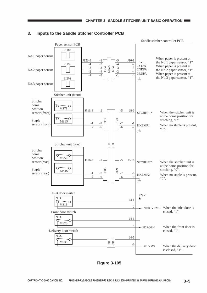
COPYRIGHT © 2000 CANON INC. FINISHER-F1/SADDLE FINISHER-F2 REV. 0 JULY 2000 PRINTED IN JAPAN (IMPRIME AU JAPON) 3-5
CHAPTER 3 SADDLE STITCHER UNIT BASIC OPERATION
3. Inputs to the Saddle Stitcher Controller PCB
Saddle stitcher controller PCB
When paper is present at the No.1 paper sensor, “1”.When paper is present at the No.2 paper sensor, “1”.When paper is present at the No.3 paper sensor, “1”.
When the stitcher unit is at the home position for stitching, “0”.
When no staple is present, “0”.
When the stitcher unit is at the home position for stitching, “0”.
When no staple is present, “0”.
PI18S
Paper sensor PCB
Stitcher unit (front)
PI19S
PI20S
MS6S
MS7S
-2-3-4
J123-5 +5V1STPA
STCHHP1*
HKEMP1
2NDPA3RDPA-1
-4-3-2
J10-1
-5-4-3-2-1
-5-2-3-4-5
-1
J204
AJ3
04
J204
-1
J315-3
-2-1
J8-3
-2-7
-5
-6-7
-5
-6
No.1 paper sensor
No.2 paper sensor
No.3 paper sensor
Stitcher home position sensor (front)
Staple sensor (front)
Stitcher home position sensor (rear)
Staple sensor (rear)
When the inlet door is closed, “1”.
When the front door is closed, “1”.
When the delivery door is closed, “1”.
Stitcher unit (rear)
MS4S
MS5S
Inlet door switch
MS1S
N.O.+24V
STCHHP2*
HKEMP2
INLTCVRMS
FDROPN
-1
J316-3
-2-8
-2
J8-10
J4-1
Front door switch
MS2S
N.O.
-4
J4-3
-9-7
-5
-6-7
-5
-6
DELVMS
Delivery door switch
MS3S
N.O.
-6
J4-5
J305
J205
JD2
JD1
J306
J121
J305
J120
Figure 3-105
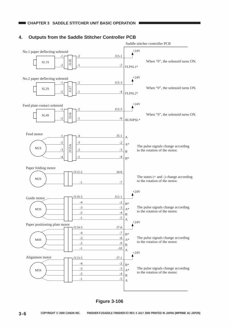
COPYRIGHT © 2000 CANON INC. FINISHER-F1/SADDLE FINISHER-F2 REV. 0 JULY 2000 PRINTED IN JAPAN (IMPRIME AU JAPON)3-6
CHAPTER 3 SADDLE STITCHER UNIT BASIC OPERATION
4. Outputs from the Saddle Stitcher Controller PCB
SL1S
J118
-1 -2
+24V
FLPSL1*
When “0”, the solenoid turns ON.
Saddle stitcher controller PCB
-2
J15-1
-2-1
SL2S
J117
-1 -2
+24V
FLPSL2*
When “0”, the solenoid turns ON.-2
J15-3
-4-1
SL4S
J116
-1 -2
+24V
RLNIPSL*
When “0”, the solenoid turns ON.-2
J15-5
-6-1
-1 -4
-4 -1
-3 -2
-2 -3
+24V
The pulse signals change according to the rotation of the motor.
J7-1
-2
A*
B*-3
B-4
A-5
J113-5
-4
-3
-2
-1
M5S
The pulse signals change according to the rotation of the motor.
J5-1
A*
A
-2
B-3
B*-4
M1S
+24V
The pulse signals change according to the rotation of the motor.
J7-6
-7
A*
B*-8
B-9
A-10
J114-5
-4
-3
-2
-1
M4S
+24V
The pulse signals change according to the rotation of the motor.
J12-1
-2
A*
B*-3
B-4
A-5
J119-5
-4
-3
-2
-1
M3S
The states (+ and -) change according to the rotation of the motor.
J4-8
-7
J112-2
-1M2S
J115
A
No.1 paper deflecting solenoid
No.2 paper deflecting solenoid
Feed plate contact solenoid
Feed motor
Paper folding motor
Guide motor
Paper positioning plate motor
Alignment motor
Figure 3-106
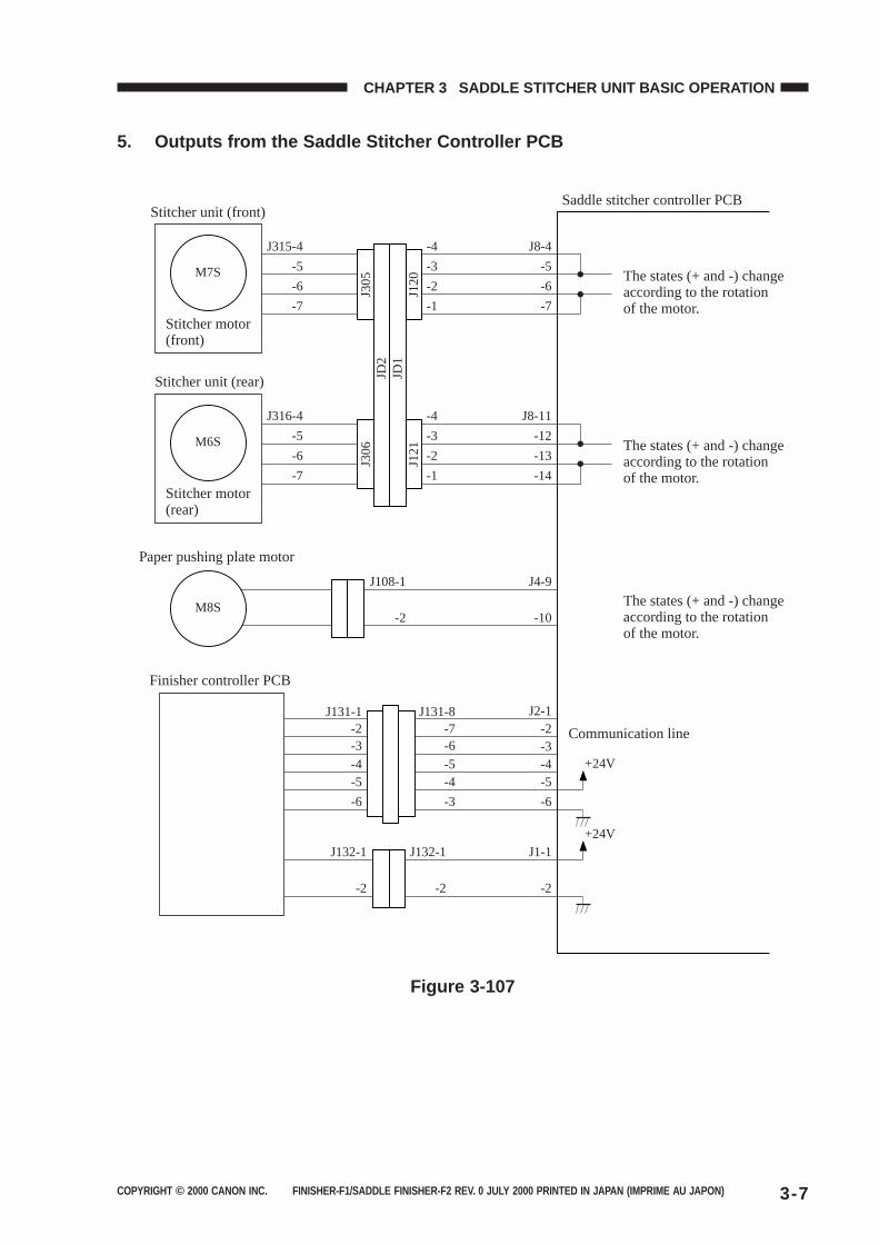
COPYRIGHT © 2000 CANON INC. FINISHER-F1/SADDLE FINISHER-F2 REV. 0 JULY 2000 PRINTED IN JAPAN (IMPRIME AU JAPON) 3-7
CHAPTER 3 SADDLE STITCHER UNIT BASIC OPERATION
5. Outputs from the Saddle Stitcher Controller PCB
Saddle stitcher controller PCB
The states (+ and -) change according to the rotation of the motor.
Stitcher unit (front)
Stitcher motor(front)
Finisher controller PCB
M7S
J315-4 J8-4
J2-1-2-3-4-5
Paper pushing plate motor
M8S
J108-1
-2
J4-9
-10
-4
-5 -5-3
-6 -6-2
-7 -7-1
J131-1 J131-8-2 -7-3 -6
-5 -4-4 -5
J132-1
-2
J132-1
-2
J1-1
-2
Communication line
+24V
+24V
-6-6 -3
J305
J120
The states (+ and -) change according to the rotation of the motor.
The states (+ and -) change according to the rotation of the motor.
Stitcher unit (rear)
Stitcher motor (rear)
M6S
J316-4 J8-11-4
-5 -12-3
-6 -13-2
-7 -14-1
J306
J121
JD1
JD2
Figure 3-107
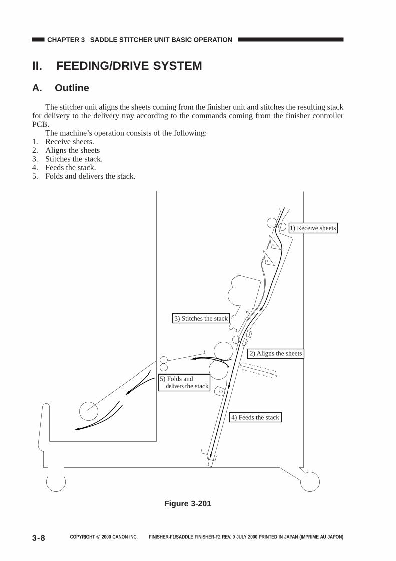
COPYRIGHT © 2000 CANON INC. FINISHER-F1/SADDLE FINISHER-F2 REV. 0 JULY 2000 PRINTED IN JAPAN (IMPRIME AU JAPON)3-8
CHAPTER 3 SADDLE STITCHER UNIT BASIC OPERATION
II. FEEDING/DRIVE SYSTEM
A. Outline
The stitcher unit aligns the sheets coming from the finisher unit and stitches the resulting stackfor delivery to the delivery tray according to the commands coming from the finisher controllerPCB.
The machine’s operation consists of the following:1. Receive sheets.2. Aligns the sheets3. Stitches the stack.4. Feeds the stack.5. Folds and delivers the stack.
1) Receive sheets
4) Feeds the stack
3) Stitches the stack
5) Folds and delivers the stack
2) Aligns the sheets
Figure 3-201
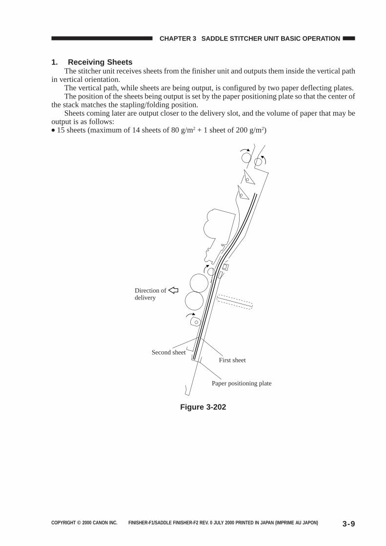
COPYRIGHT © 2000 CANON INC. FINISHER-F1/SADDLE FINISHER-F2 REV. 0 JULY 2000 PRINTED IN JAPAN (IMPRIME AU JAPON) 3-9
CHAPTER 3 SADDLE STITCHER UNIT BASIC OPERATION
1. Receiving SheetsThe stitcher unit receives sheets from the finisher unit and outputs them inside the vertical path
in vertical orientation.The vertical path, while sheets are being output, is configured by two paper deflecting plates.The position of the sheets being output is set by the paper positioning plate so that the center of
the stack matches the stapling/folding position.Sheets coming later are output closer to the delivery slot, and the volume of paper that may be
output is as follows:● 15 sheets (maximum of 14 sheets of 80 g/m2 + 1 sheet of 200 g/m2)
Paper positioning plate
First sheetSecond sheet
Direction of delivery
Figure 3-202
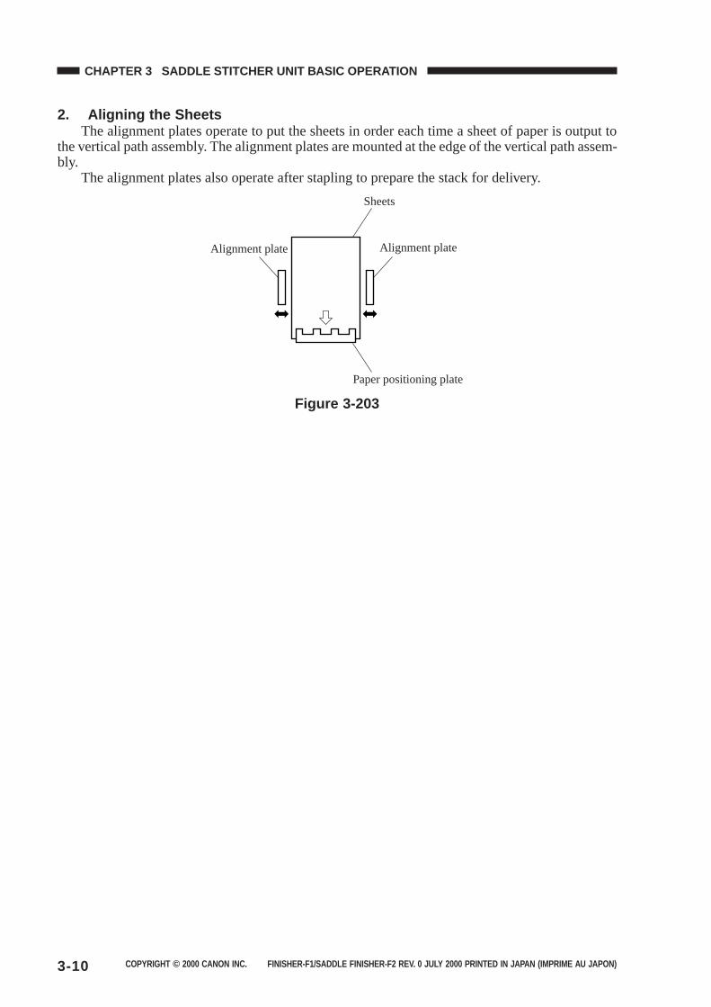
COPYRIGHT © 2000 CANON INC. FINISHER-F1/SADDLE FINISHER-F2 REV. 0 JULY 2000 PRINTED IN JAPAN (IMPRIME AU JAPON)3-10
CHAPTER 3 SADDLE STITCHER UNIT BASIC OPERATION
2. Aligning the SheetsThe alignment plates operate to put the sheets in order each time a sheet of paper is output to
the vertical path assembly. The alignment plates are mounted at the edge of the vertical path assem-bly.
The alignment plates also operate after stapling to prepare the stack for delivery.
Sheets
Paper positioning plate
Alignment plateAlignment plate
Figure 3-203
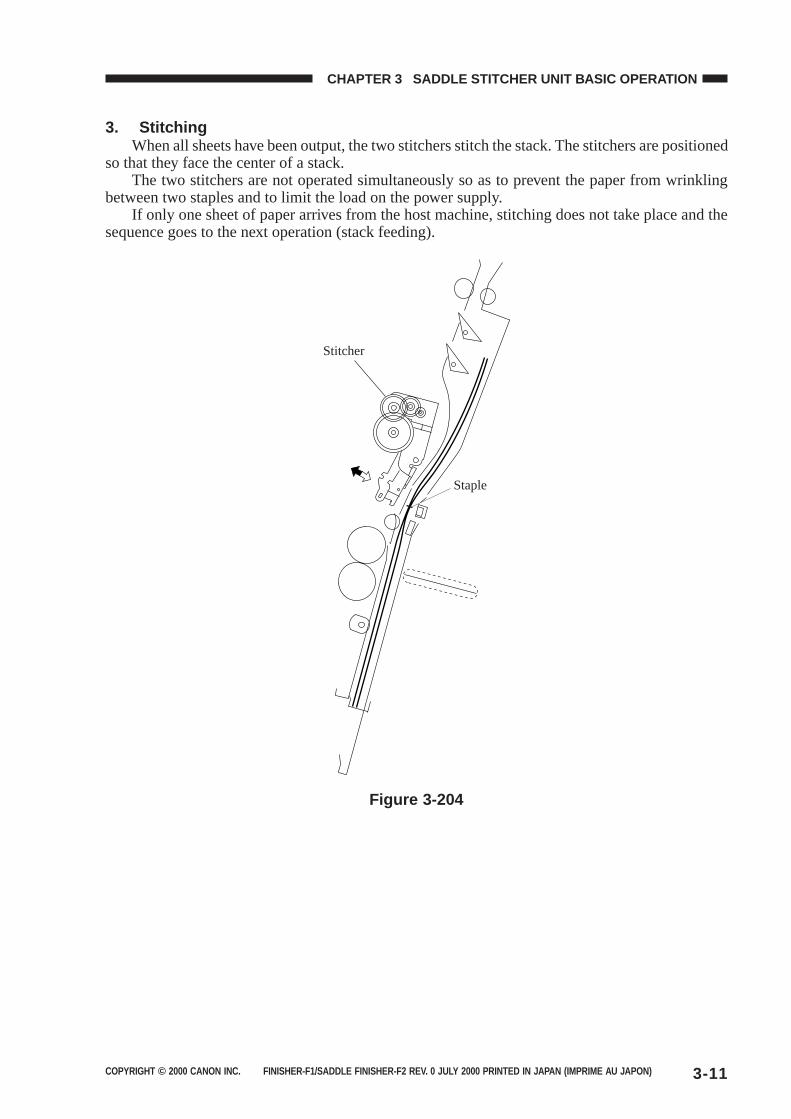
COPYRIGHT © 2000 CANON INC. FINISHER-F1/SADDLE FINISHER-F2 REV. 0 JULY 2000 PRINTED IN JAPAN (IMPRIME AU JAPON) 3-11
CHAPTER 3 SADDLE STITCHER UNIT BASIC OPERATION
3. StitchingWhen all sheets have been output, the two stitchers stitch the stack. The stitchers are positioned
so that they face the center of a stack.The two stitchers are not operated simultaneously so as to prevent the paper from wrinkling
between two staples and to limit the load on the power supply.If only one sheet of paper arrives from the host machine, stitching does not take place and the
sequence goes to the next operation (stack feeding).
Stitcher
Staple
Figure 3-204
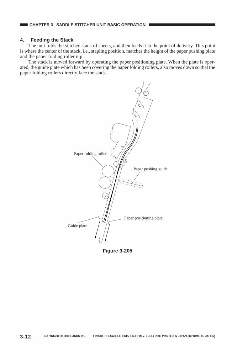
COPYRIGHT © 2000 CANON INC. FINISHER-F1/SADDLE FINISHER-F2 REV. 0 JULY 2000 PRINTED IN JAPAN (IMPRIME AU JAPON)3-12
CHAPTER 3 SADDLE STITCHER UNIT BASIC OPERATION
4. Feeding the StackThe unit folds the stitched stack of sheets, and then feeds it to the point of delivery. This point
is where the center of the stack, i.e., stapling position, matches the height of the paper pushing plateand the paper folding roller nip.
The stack is moved forward by operating the paper positioning plate. When the plate is oper-ated, the guide plate which has been covering the paper folding rollers, also moves down so that thepaper folding rollers directly face the stack.
Paper folding roller
Guide plate
Paper positioning plate
Paper pushing guide
Figure 3-205
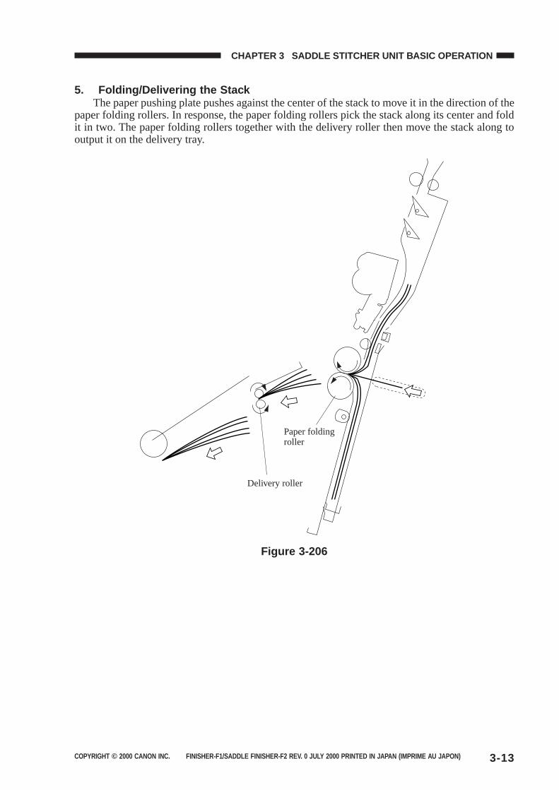
COPYRIGHT © 2000 CANON INC. FINISHER-F1/SADDLE FINISHER-F2 REV. 0 JULY 2000 PRINTED IN JAPAN (IMPRIME AU JAPON) 3-13
CHAPTER 3 SADDLE STITCHER UNIT BASIC OPERATION
5. Folding/Delivering the StackThe paper pushing plate pushes against the center of the stack to move it in the direction of the
paper folding rollers. In response, the paper folding rollers pick the stack along its center and foldit in two. The paper folding rollers together with the delivery roller then move the stack along tooutput it on the delivery tray.
Delivery roller
Paper folding roller
Figure 3-206
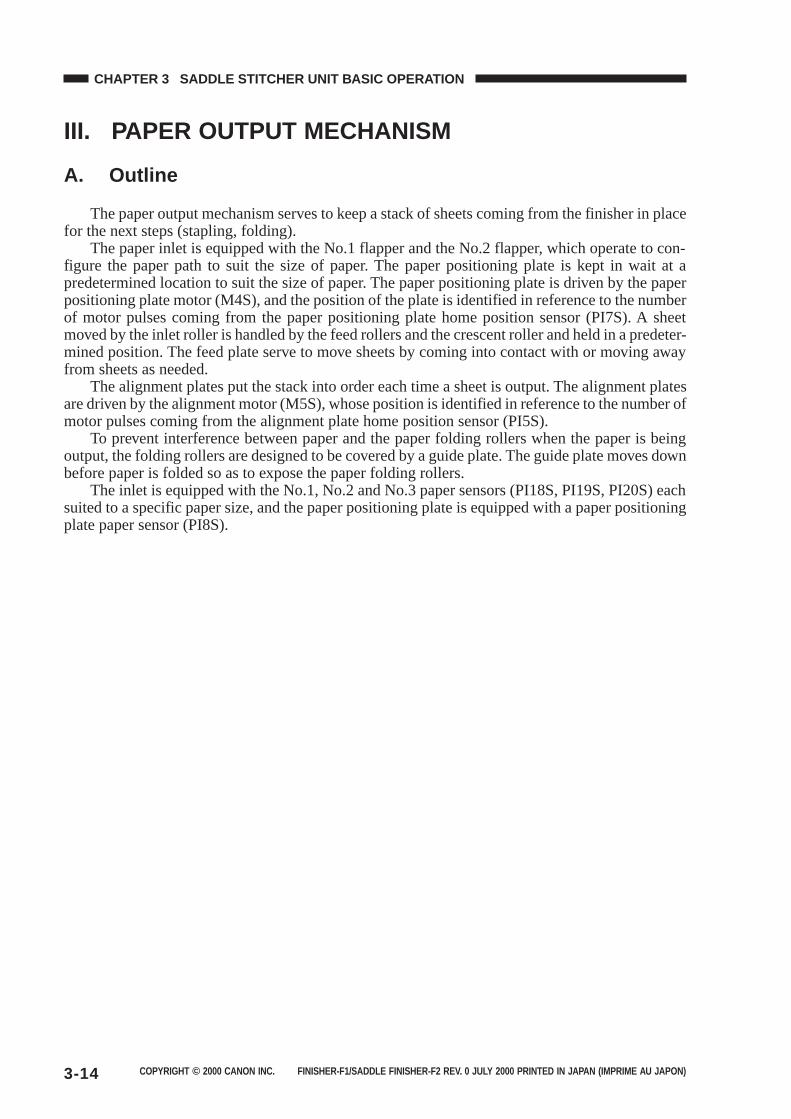
COPYRIGHT © 2000 CANON INC. FINISHER-F1/SADDLE FINISHER-F2 REV. 0 JULY 2000 PRINTED IN JAPAN (IMPRIME AU JAPON)3-14
CHAPTER 3 SADDLE STITCHER UNIT BASIC OPERATION
III. PAPER OUTPUT MECHANISM
A. Outline
The paper output mechanism serves to keep a stack of sheets coming from the finisher in placefor the next steps (stapling, folding).
The paper inlet is equipped with the No.1 flapper and the No.2 flapper, which operate to con-figure the paper path to suit the size of paper. The paper positioning plate is kept in wait at apredetermined location to suit the size of paper. The paper positioning plate is driven by the paperpositioning plate motor (M4S), and the position of the plate is identified in reference to the numberof motor pulses coming from the paper positioning plate home position sensor (PI7S). A sheetmoved by the inlet roller is handled by the feed rollers and the crescent roller and held in a predeter-mined position. The feed plate serve to move sheets by coming into contact with or moving awayfrom sheets as needed.
The alignment plates put the stack into order each time a sheet is output. The alignment platesare driven by the alignment motor (M5S), whose position is identified in reference to the number ofmotor pulses coming from the alignment plate home position sensor (PI5S).
To prevent interference between paper and the paper folding rollers when the paper is beingoutput, the folding rollers are designed to be covered by a guide plate. The guide plate moves downbefore paper is folded so as to expose the paper folding rollers.
The inlet is equipped with the No.1, No.2 and No.3 paper sensors (PI18S, PI19S, PI20S) eachsuited to a specific paper size, and the paper positioning plate is equipped with a paper positioningplate paper sensor (PI8S).
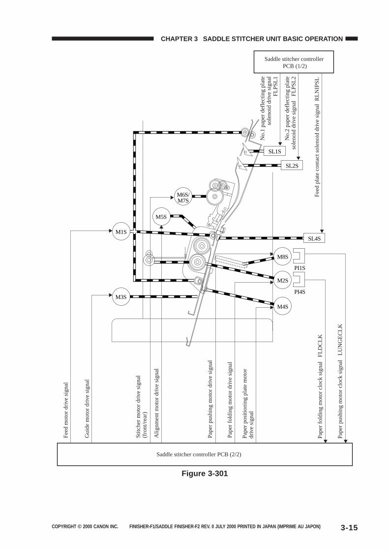
COPYRIGHT © 2000 CANON INC. FINISHER-F1/SADDLE FINISHER-F2 REV. 0 JULY 2000 PRINTED IN JAPAN (IMPRIME AU JAPON) 3-15
CHAPTER 3 SADDLE STITCHER UNIT BASIC OPERATION
SL1S
SL4S
SL2S
M8S
M6S/M7S
M1S
M5S
M3S
PI1S
M2S
M4S
PI4S
Fee
d m
otor
driv
e si
gnal
Gui
de m
otor
driv
e si
gnal
Stit
cher
mot
or d
rive
sign
al
(fro
nt/r
ear)
Pap
er p
ushi
ng m
otor
driv
e si
gnal
Alig
nmen
t mot
or d
rive
sign
al
Pap
er p
ushi
ng m
otor
clo
ck s
igna
l L
UN
GE
CLK
No.
1 pa
per
defle
ctin
g pl
ate
sole
noid
driv
e si
gnal
FLP
SL1
No.
2 pa
per
defle
ctin
g pl
ate
sole
noid
driv
e si
gnal
F
LPS
L2
Fee
d pl
ate
cont
act s
olen
oid
driv
e si
gnal
RLN
IPS
LP
aper
fold
ing
mot
or c
lock
sig
nal
FLD
CLK
Pap
er fo
ldin
g m
otor
driv
e si
gnal
Pap
er p
ositi
onin
g pl
ate
mot
or
driv
e si
gnal
Saddle stitcher controller PCB (1/2)
Saddle stitcher controller PCB (2/2)
Figure 3-301
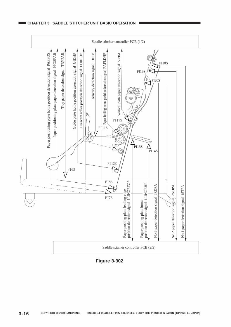
COPYRIGHT © 2000 CANON INC. FINISHER-F1/SADDLE FINISHER-F2 REV. 0 JULY 2000 PRINTED IN JAPAN (IMPRIME AU JAPON)3-16
CHAPTER 3 SADDLE STITCHER UNIT BASIC OPERATION
Saddle stitcher controller PCB (2/2)
Saddle stitcher controller PCB (1/2)
PI19S
PI18S
PI20S
PI15SPI14S
Pap
er p
ushi
ng p
late
lead
ing
edge
po
sitio
n de
tect
ion
sign
al L
UN
GE
TO
P
Pap
er p
ushi
ng p
late
hom
e po
sitio
n de
tect
ion
sign
al L
UN
GE
HP
No.
3 pa
per
dete
ctio
n si
gnal
3R
DP
A
No.
2 pa
per
dete
ctio
n si
gnal
2N
DP
A
No.
1 pa
per
dete
ctio
n si
gnal
1S
TP
A
PI21S
Pap
er p
ositi
onin
g pl
ate
hom
e po
sitio
n de
tect
ion
sign
al P
AP
PO
S
Pap
er p
ositi
onin
g pl
ate
pape
r de
tect
ion
sign
al
PP
OS
PA
R
Tra
y pa
per
dete
ctio
n si
gnal
TR
YP
AR
Gui
de p
late
hom
e po
sitio
n de
tect
ion
sign
al G
IDH
P
Cre
scen
t rol
ler
posi
tion
dete
ctio
n si
gnal
FD
RLH
P
Del
iver
y de
tect
ion
sign
al D
EIV
Pape
r fol
ding
hom
e po
sitio
n de
tect
ion
sign
al P
AF
LDH
P
Vert
ical
pat
h pa
per
dete
ctio
n si
gnal
V
PJM
Figure 3-302
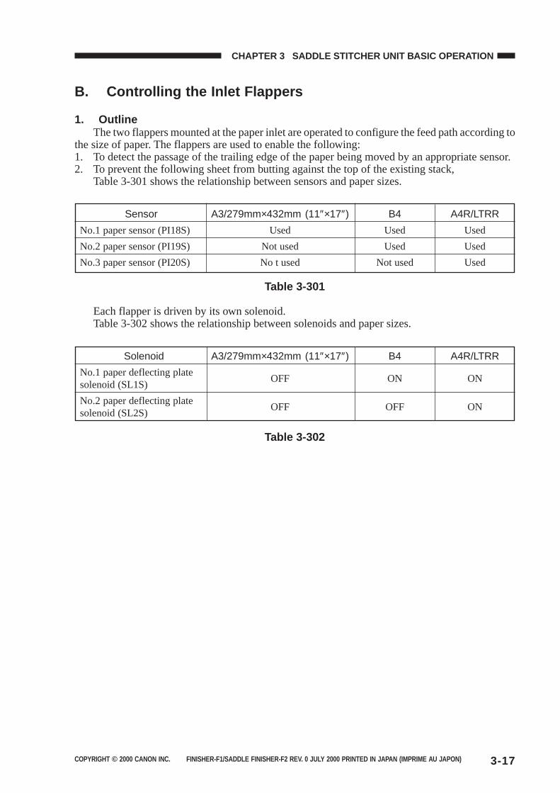
COPYRIGHT © 2000 CANON INC. FINISHER-F1/SADDLE FINISHER-F2 REV. 0 JULY 2000 PRINTED IN JAPAN (IMPRIME AU JAPON) 3-17
CHAPTER 3 SADDLE STITCHER UNIT BASIC OPERATION
B. Controlling the Inlet Flappers
1. OutlineThe two flappers mounted at the paper inlet are operated to configure the feed path according to
the size of paper. The flappers are used to enable the following:1. To detect the passage of the trailing edge of the paper being moved by an appropriate sensor.2. To prevent the following sheet from butting against the top of the existing stack,
Table 3-301 shows the relationship between sensors and paper sizes.
Sensor A3/279mm×432mm (11″×17″) B4 A4R/LTRR
No.1 paper sensor (PI18S) Used Used Used
No.2 paper sensor (PI19S) Not used Used Used
No.3 paper sensor (PI20S) No t used Not used Used
Table 3-301
Each flapper is driven by its own solenoid.Table 3-302 shows the relationship between solenoids and paper sizes.
Solenoid A3/279mm×432mm (11″×17″) B4 A4R/LTRR
No.1 paper deflecting plateOFF ON ON
solenoid (SL1S)
No.2 paper deflecting plateOFF OFF ON
solenoid (SL2S)
Table 3-302
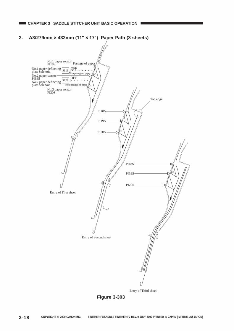
COPYRIGHT © 2000 CANON INC. FINISHER-F1/SADDLE FINISHER-F2 REV. 0 JULY 2000 PRINTED IN JAPAN (IMPRIME AU JAPON)3-18
CHAPTER 3 SADDLE STITCHER UNIT BASIC OPERATION
2. A3/279mm ××××× 432mm (11 ″″″″″ ××××× 17″″″″″) Paper Path (3 sheets)
SL1S
SL2S
OFF
OFF
No.1 paper sensorPI18S
PI19S
PI20S
No.2 paper sensor
No.3 paper sensor
No.1 paper deflecting plate solenoid
No.2 paper deflecting plate solenoid
Passage of paper
Non-passage of paper
Non-passage of paper
Entry of First sheet
PI18S
PI19S
PI20S
Top edge
Entry of Second sheet
PI18S
PI19S
PI20S
Entry of Third sheet
Figure 3-303
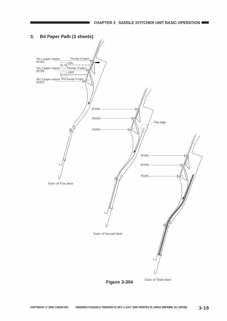
COPYRIGHT © 2000 CANON INC. FINISHER-F1/SADDLE FINISHER-F2 REV. 0 JULY 2000 PRINTED IN JAPAN (IMPRIME AU JAPON) 3-19
CHAPTER 3 SADDLE STITCHER UNIT BASIC OPERATION
3. B4 Paper Path (3 sheets)
SL1S
SL2S
ON
OFF
No.1 paper sensorPI18S
PI19S
PI20S
No.2 paper sensor
No.3 paper sensor
Passage of paper
Passage of paper
Non-passage of paper
Entry of First sheet
PI18S
PI19S
PI20S
Entry of Second sheet
PI18S
PI19S
PI20S
Entry of Third sheet
Top edge
Figure 3-304
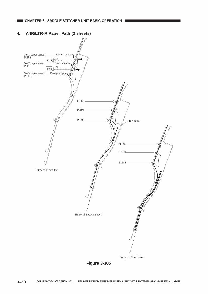
COPYRIGHT © 2000 CANON INC. FINISHER-F1/SADDLE FINISHER-F2 REV. 0 JULY 2000 PRINTED IN JAPAN (IMPRIME AU JAPON)3-20
CHAPTER 3 SADDLE STITCHER UNIT BASIC OPERATION
4. A4R/LTR-R Paper Path (3 sheets)
SL1S
SL2S
ON
ON
No.1 paper sensorPI18S
PI19S
PI20S
No.2 paper sensor
No.3 paper sensor
Passage of paper
Passage of paper
Passage of paper
Entry of First sheet
PI18S
PI19S
PI20S
Entry of Second sheet
PI18S
PI19S
PI20S
Entry of Third sheet
Top edge
Figure 3-305
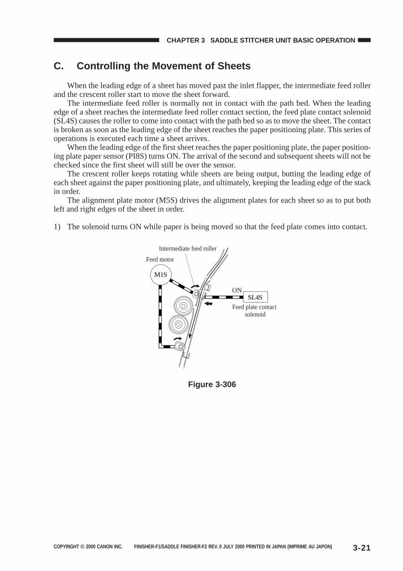
COPYRIGHT © 2000 CANON INC. FINISHER-F1/SADDLE FINISHER-F2 REV. 0 JULY 2000 PRINTED IN JAPAN (IMPRIME AU JAPON) 3-21
CHAPTER 3 SADDLE STITCHER UNIT BASIC OPERATION
C. Controlling the Movement of Sheets
When the leading edge of a sheet has moved past the inlet flapper, the intermediate feed rollerand the crescent roller start to move the sheet forward.
The intermediate feed roller is normally not in contact with the path bed. When the leadingedge of a sheet reaches the intermediate feed roller contact section, the feed plate contact solenoid(SL4S) causes the roller to come into contact with the path bed so as to move the sheet. The contactis broken as soon as the leading edge of the sheet reaches the paper positioning plate. This series ofoperations is executed each time a sheet arrives.
When the leading edge of the first sheet reaches the paper positioning plate, the paper position-ing plate paper sensor (PI8S) turns ON. The arrival of the second and subsequent sheets will not bechecked since the first sheet will still be over the sensor.
The crescent roller keeps rotating while sheets are being output, butting the leading edge ofeach sheet against the paper positioning plate, and ultimately, keeping the leading edge of the stackin order.
The alignment plate motor (M5S) drives the alignment plates for each sheet so as to put bothleft and right edges of the sheet in order.
1) The solenoid turns ON while paper is being moved so that the feed plate comes into contact.
SL4S
Feed plate contact solenoid
ON
Feed motor
Intermediate feed roller
M1S
Figure 3-306
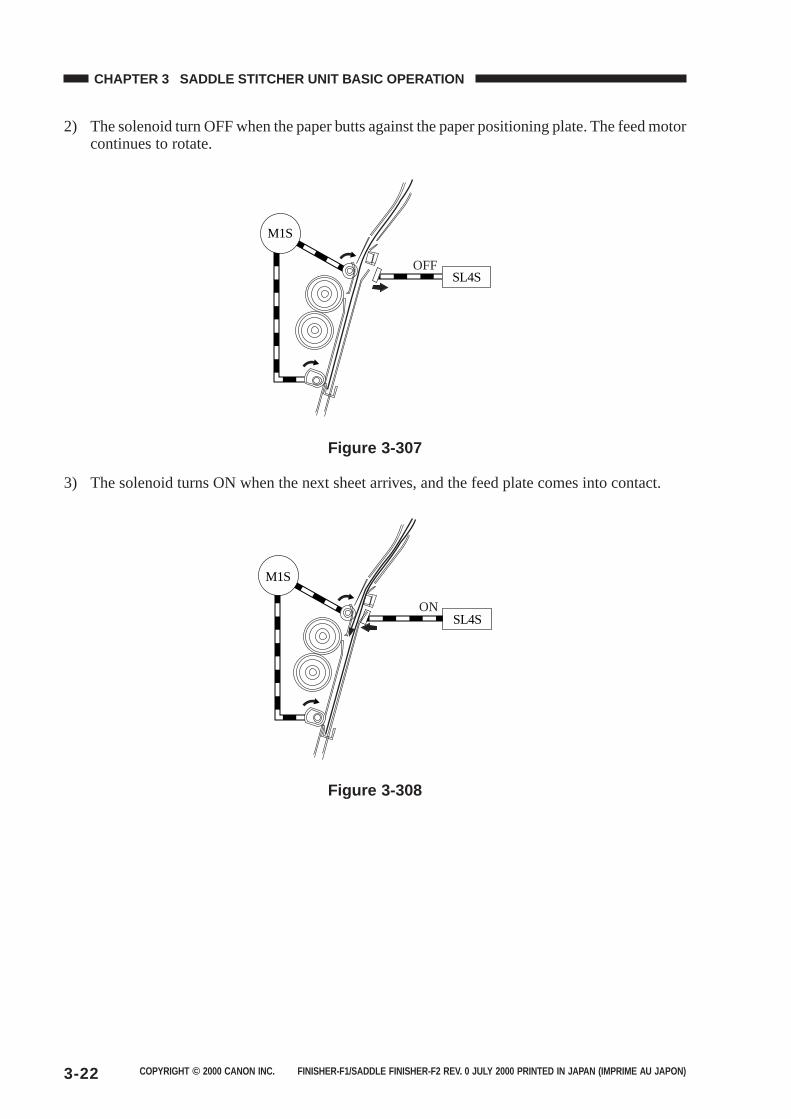
COPYRIGHT © 2000 CANON INC. FINISHER-F1/SADDLE FINISHER-F2 REV. 0 JULY 2000 PRINTED IN JAPAN (IMPRIME AU JAPON)3-22
CHAPTER 3 SADDLE STITCHER UNIT BASIC OPERATION
2) The solenoid turn OFF when the paper butts against the paper positioning plate. The feed motorcontinues to rotate.
SL4SOFF
M1S
Figure 3-307
3) The solenoid turns ON when the next sheet arrives, and the feed plate comes into contact.
SL4SON
M1S
Figure 3-308
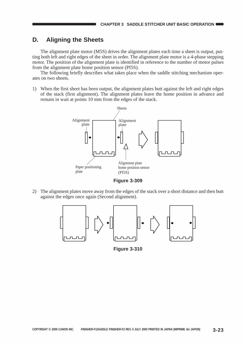
COPYRIGHT © 2000 CANON INC. FINISHER-F1/SADDLE FINISHER-F2 REV. 0 JULY 2000 PRINTED IN JAPAN (IMPRIME AU JAPON) 3-23
CHAPTER 3 SADDLE STITCHER UNIT BASIC OPERATION
D. Aligning the Sheets
The alignment plate motor (M5S) drives the alignment plates each time a sheet is output, put-ting both left and right edges of the sheet in order. The alignment plate motor is a 4-phase steppingmotor. The position of the alignment plate is identified in reference to the number of motor pulsesfrom the alignment plate home position sensor (PI5S).
The following briefly describes what takes place when the saddle stitching mechanism oper-ates on two sheets.
1) When the first sheet has been output, the alignment plates butt against the left and right edgesof the stack (first alignment). The alignment plates leave the home position in advance andremain in wait at points 10 mm from the edges of the stack.
Sheets
Paper positioning plate
Alignmentplate
Alignmentplate
Alignment plate home position sensor(PI5S)
Figure 3-309
2) The alignment plates move away from the edges of the stack over a short distance and then buttagainst the edges once again (Second alignment).
Figure 3-310
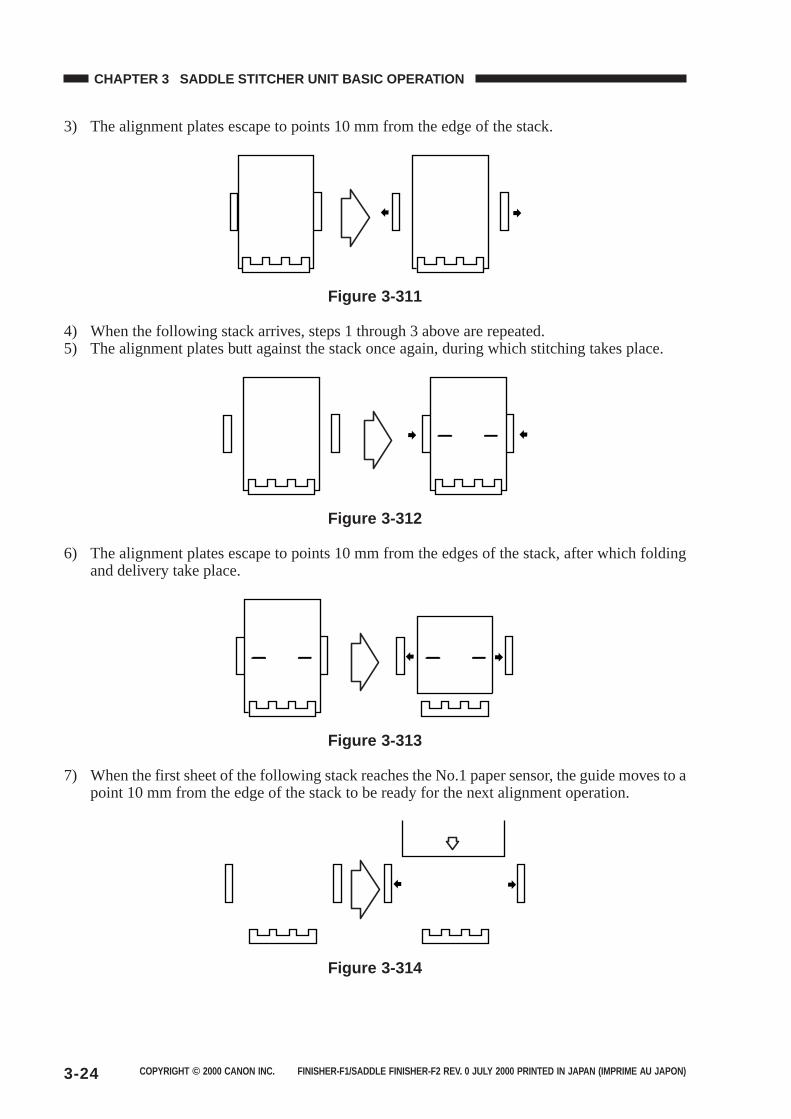
COPYRIGHT © 2000 CANON INC. FINISHER-F1/SADDLE FINISHER-F2 REV. 0 JULY 2000 PRINTED IN JAPAN (IMPRIME AU JAPON)3-24
CHAPTER 3 SADDLE STITCHER UNIT BASIC OPERATION
3) The alignment plates escape to points 10 mm from the edge of the stack.
Figure 3-311
4) When the following stack arrives, steps 1 through 3 above are repeated.5) The alignment plates butt against the stack once again, during which stitching takes place.
Figure 3-312
6) The alignment plates escape to points 10 mm from the edges of the stack, after which foldingand delivery take place.
Figure 3-313
7) When the first sheet of the following stack reaches the No.1 paper sensor, the guide moves to apoint 10 mm from the edge of the stack to be ready for the next alignment operation.
Figure 3-314
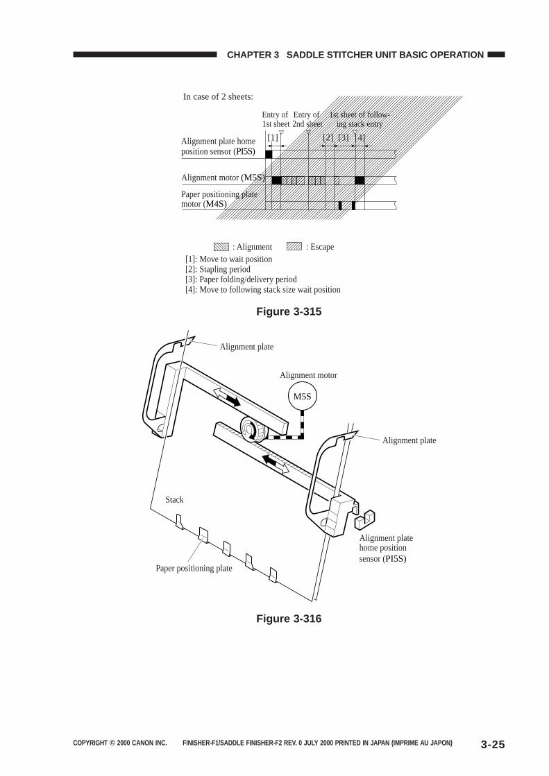
COPYRIGHT © 2000 CANON INC. FINISHER-F1/SADDLE FINISHER-F2 REV. 0 JULY 2000 PRINTED IN JAPAN (IMPRIME AU JAPON) 3-25
CHAPTER 3 SADDLE STITCHER UNIT BASIC OPERATION
Alignment plate home position sensor (PI5S)
Paper positioning plate motor (M4S)
Alignment motor (M5S)
: Alignment : Escape
Entry of 1st sheet
Entry of 2nd sheet
1st sheet of follow-ing stack entry
In case of 2 sheets:
[1]: Move to wait position[2]: Stapling period[3]: Paper folding/delivery period[4]: Move to following stack size wait position
[1] [2] [3] [4]
Figure 3-315
M5S
Alignment motor
Alignment plate
Alignment plate
Alignment plate home position sensor (PI5S)
Stack
Paper positioning plate
Figure 3-316
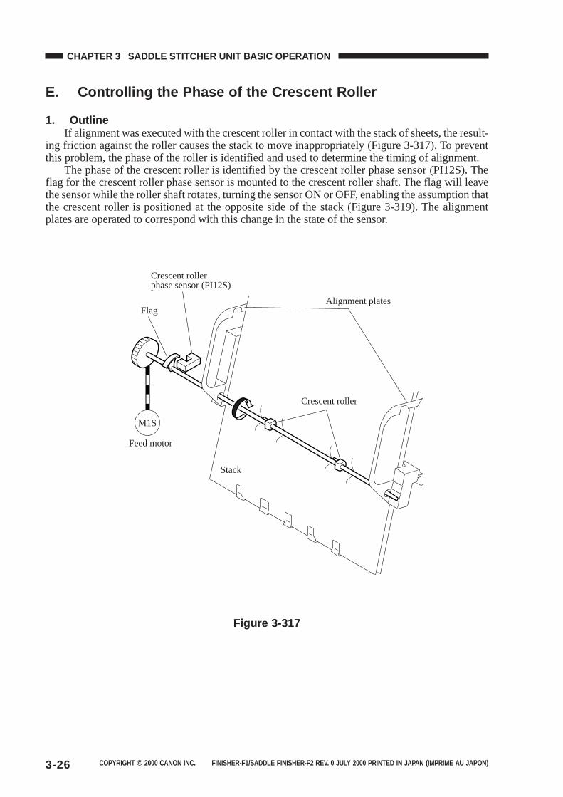
COPYRIGHT © 2000 CANON INC. FINISHER-F1/SADDLE FINISHER-F2 REV. 0 JULY 2000 PRINTED IN JAPAN (IMPRIME AU JAPON)3-26
CHAPTER 3 SADDLE STITCHER UNIT BASIC OPERATION
E. Controlling the Phase of the Crescent Roller
1. OutlineIf alignment was executed with the crescent roller in contact with the stack of sheets, the result-
ing friction against the roller causes the stack to move inappropriately (Figure 3-317). To preventthis problem, the phase of the roller is identified and used to determine the timing of alignment.
The phase of the crescent roller is identified by the crescent roller phase sensor (PI12S). Theflag for the crescent roller phase sensor is mounted to the crescent roller shaft. The flag will leavethe sensor while the roller shaft rotates, turning the sensor ON or OFF, enabling the assumption thatthe crescent roller is positioned at the opposite side of the stack (Figure 3-319). The alignmentplates are operated to correspond with this change in the state of the sensor.
Crescent roller phase sensor (PI12S)
Flag
Feed motor
Stack
Crescent roller
Alignment plates
M1S
Figure 3-317
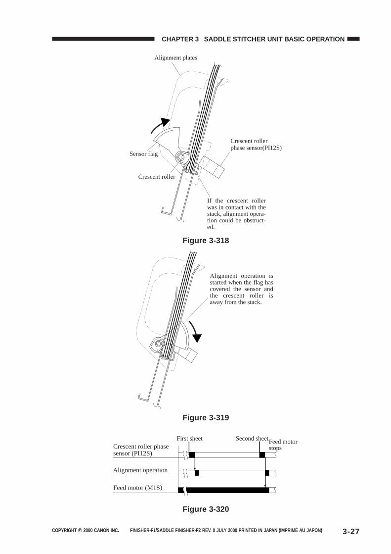
COPYRIGHT © 2000 CANON INC. FINISHER-F1/SADDLE FINISHER-F2 REV. 0 JULY 2000 PRINTED IN JAPAN (IMPRIME AU JAPON) 3-27
CHAPTER 3 SADDLE STITCHER UNIT BASIC OPERATION
Alignment plates
Crescent roller phase sensor(PI12S)
If the crescent roller was in contact with the stack, alignment opera-tion could be obstruct-ed.
Sensor flag
Crescent roller
Figure 3-318
Alignment operation is started when the flag has covered the sensor and the crescent roller is away from the stack.
Figure 3-319
Crescent roller phase sensor (PI12S)
First sheet Second sheetFeed motor stops
Alignment operation
Feed motor (M1S)
Figure 3-320
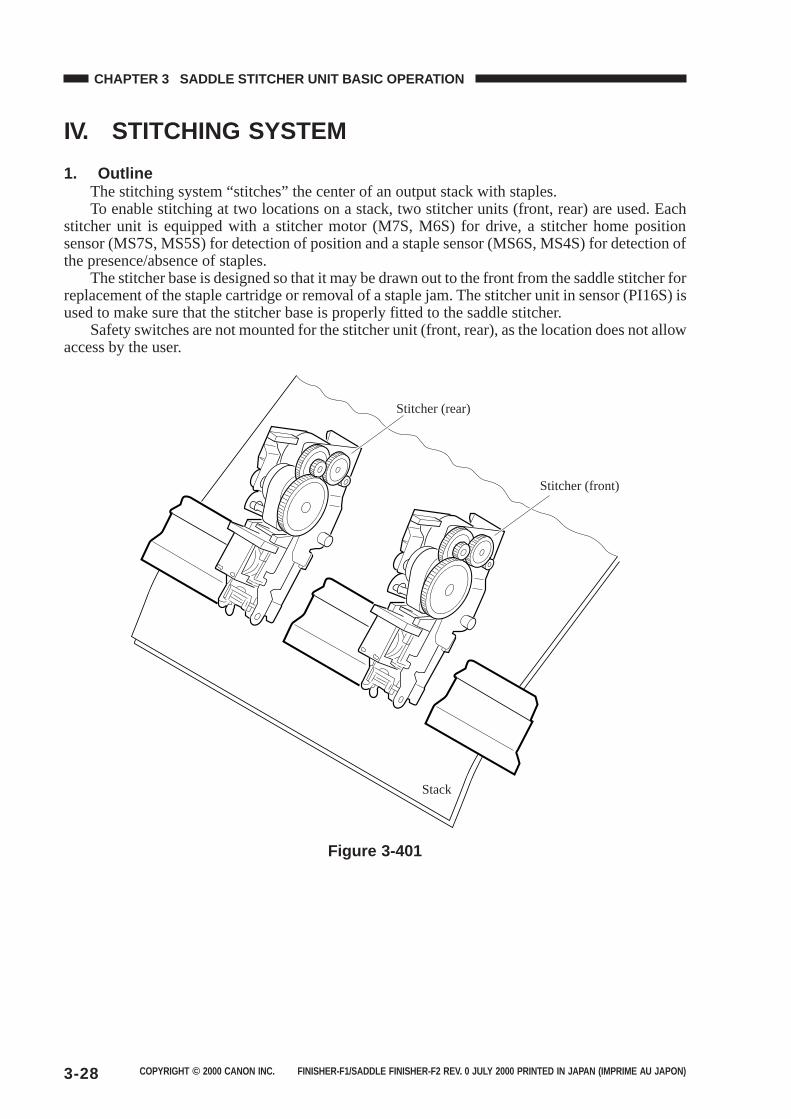
COPYRIGHT © 2000 CANON INC. FINISHER-F1/SADDLE FINISHER-F2 REV. 0 JULY 2000 PRINTED IN JAPAN (IMPRIME AU JAPON)3-28
CHAPTER 3 SADDLE STITCHER UNIT BASIC OPERATION
IV. STITCHING SYSTEM
1. OutlineThe stitching system “stitches” the center of an output stack with staples.To enable stitching at two locations on a stack, two stitcher units (front, rear) are used. Each
stitcher unit is equipped with a stitcher motor (M7S, M6S) for drive, a stitcher home positionsensor (MS7S, MS5S) for detection of position and a staple sensor (MS6S, MS4S) for detection ofthe presence/absence of staples.
The stitcher base is designed so that it may be drawn out to the front from the saddle stitcher forreplacement of the staple cartridge or removal of a staple jam. The stitcher unit in sensor (PI16S) isused to make sure that the stitcher base is properly fitted to the saddle stitcher.
Safety switches are not mounted for the stitcher unit (front, rear), as the location does not allowaccess by the user.
Stitcher (rear)
Stitcher (front)
Stack
Figure 3-401
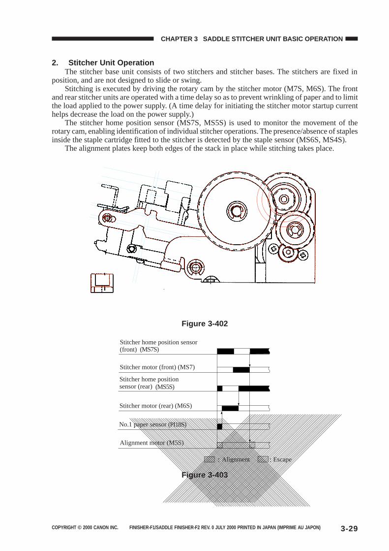
COPYRIGHT © 2000 CANON INC. FINISHER-F1/SADDLE FINISHER-F2 REV. 0 JULY 2000 PRINTED IN JAPAN (IMPRIME AU JAPON) 3-29
CHAPTER 3 SADDLE STITCHER UNIT BASIC OPERATION
2. Stitcher Unit OperationThe stitcher base unit consists of two stitchers and stitcher bases. The stitchers are fixed in
position, and are not designed to slide or swing.Stitching is executed by driving the rotary cam by the stitcher motor (M7S, M6S). The front
and rear stitcher units are operated with a time delay so as to prevent wrinkling of paper and to limitthe load applied to the power supply. (A time delay for initiating the stitcher motor startup currenthelps decrease the load on the power supply.)
The stitcher home position sensor (MS7S, MS5S) is used to monitor the movement of therotary cam, enabling identification of individual stitcher operations. The presence/absence of staplesinside the staple cartridge fitted to the stitcher is detected by the staple sensor (MS6S, MS4S).
The alignment plates keep both edges of the stack in place while stitching takes place.
Figure 3-402
(MS7S)
(MS5S)
(PI18S)
Stitcher home position sensor (front)
Stitcher motor (front) (MS7)
Stitcher motor (rear) (M6S)
Stitcher home position sensor (rear)
No.1 paper sensor
Alignment motor (M5S)
Alignment Escape
Figure 3-403
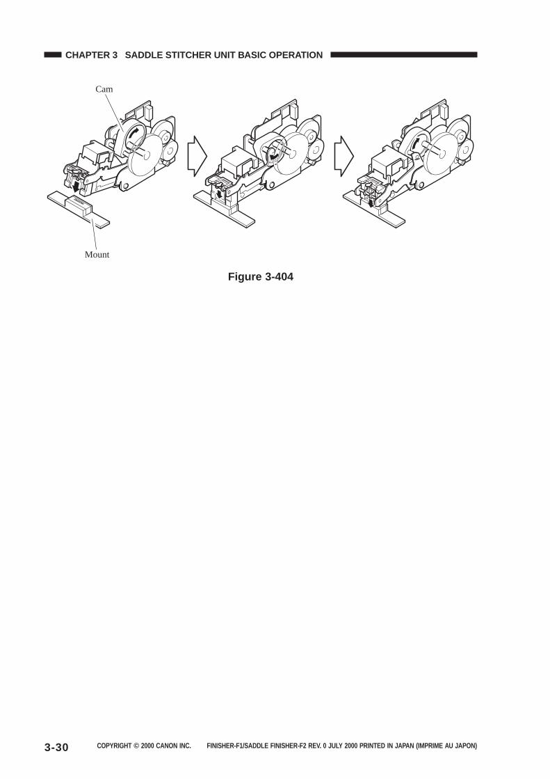
COPYRIGHT © 2000 CANON INC. FINISHER-F1/SADDLE FINISHER-F2 REV. 0 JULY 2000 PRINTED IN JAPAN (IMPRIME AU JAPON)3-30
CHAPTER 3 SADDLE STITCHER UNIT BASIC OPERATION
Cam
Mount
Figure 3-404

COPYRIGHT © 2000 CANON INC. FINISHER-F1/SADDLE FINISHER-F2 REV. 0 JULY 2000 PRINTED IN JAPAN (IMPRIME AU JAPON) 3-31
CHAPTER 3 SADDLE STITCHER UNIT BASIC OPERATION
V. FOLDING/DELIVERY SYSTEM
1. OutlineThe paper folding mechanism consists of a guide plate, paper folding rollers, paper pushing
plate, and paper positioning plate.The guide plate is used to cover the folding rollers while sheets are output so as to prevent
sheets from coming into contact with the folding rollers during output. Before the stack is folded,the guide plate moves down to enable the folding rollers to operate.
The folding rollers are driven by the paper folding motor (M2S), and the drive of the motor ismonitored by the paper folding motor clock sensor (PI4S). The mechanism is also equipped with apaper folding home position sensor (PI21S) for detecting the position of the paper folding rollers.
The paper pushing plate is driven by the paper pushing plate motor (M8S), and the drive of thepaper pushing plate motor is monitored by the paper pushing plate motor clock sensor (PI1S). Thepaper pushing plate home position sensor (PI14S) and the paper pushing plate top position sensor(PI15S) are used to detect the position of the paper pushing plate.
After being folded into two by the paper folding rollers, a stack is moved ahead by the deliveryroller for delivery. The delivery roller is driven by the paper folding motor. The delivery sensor(PI11S) is mounted to the delivery assembly to detect delivery of paper. The tray paper sensor(PI6S) is used to detect the presence/absence of paper on the tray, but does not detect jams. Thevertical path paper sensor (PI17S) serves to detect the presence of paper after jam removal.
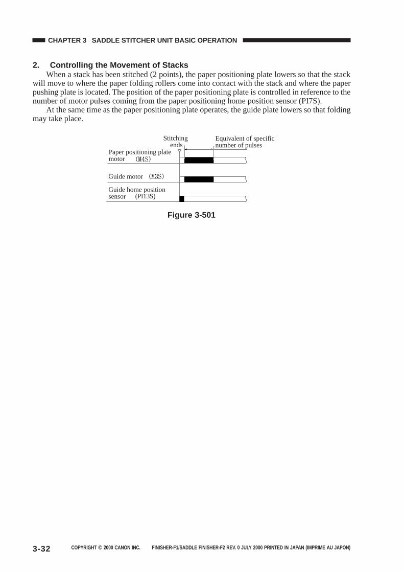
COPYRIGHT © 2000 CANON INC. FINISHER-F1/SADDLE FINISHER-F2 REV. 0 JULY 2000 PRINTED IN JAPAN (IMPRIME AU JAPON)3-32
CHAPTER 3 SADDLE STITCHER UNIT BASIC OPERATION
2. Controlling the Movement of StacksWhen a stack has been stitched (2 points), the paper positioning plate lowers so that the stack
will move to where the paper folding rollers come into contact with the stack and where the paperpushing plate is located. The position of the paper positioning plate is controlled in reference to thenumber of motor pulses coming from the paper positioning home position sensor (PI7S).
At the same time as the paper positioning plate operates, the guide plate lowers so that foldingmay take place.
(PI13S)
Stitching ends
Equivalent of specific number of pulses
Paper positioning plate motor
Guide motor
Guide home position sensor
Figure 3-501
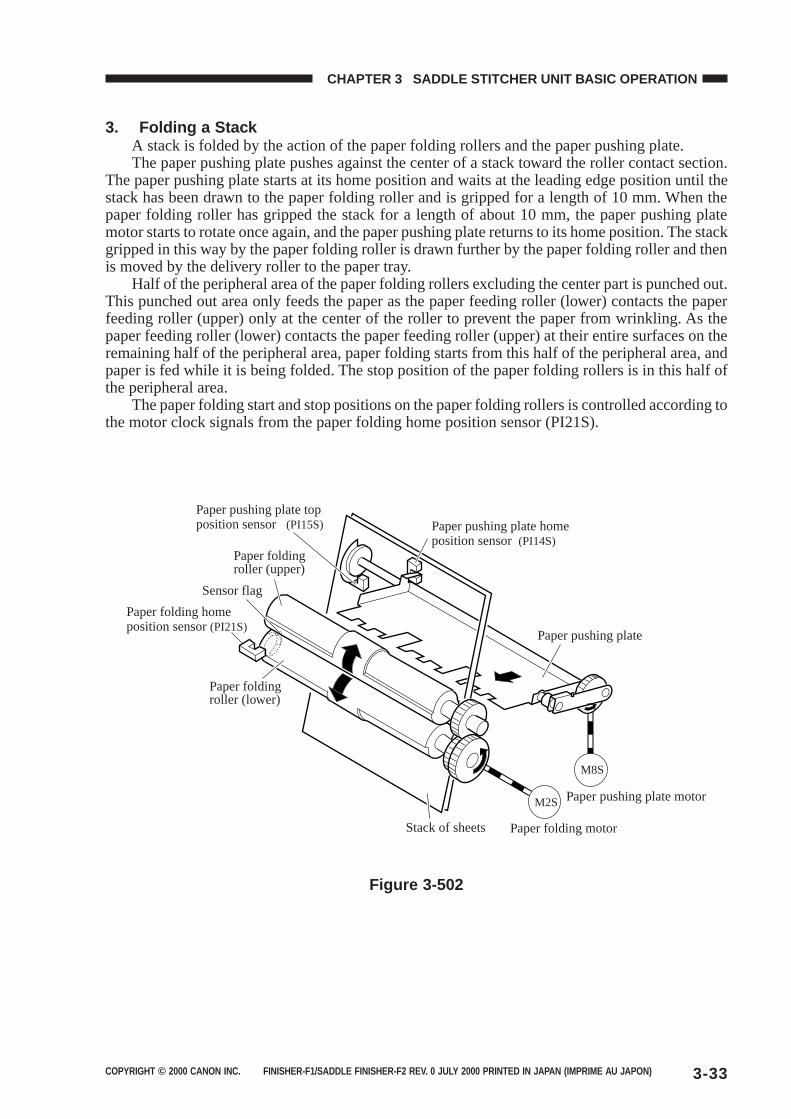
COPYRIGHT © 2000 CANON INC. FINISHER-F1/SADDLE FINISHER-F2 REV. 0 JULY 2000 PRINTED IN JAPAN (IMPRIME AU JAPON) 3-33
CHAPTER 3 SADDLE STITCHER UNIT BASIC OPERATION
3. Folding a StackA stack is folded by the action of the paper folding rollers and the paper pushing plate.The paper pushing plate pushes against the center of a stack toward the roller contact section.
The paper pushing plate starts at its home position and waits at the leading edge position until thestack has been drawn to the paper folding roller and is gripped for a length of 10 mm. When thepaper folding roller has gripped the stack for a length of about 10 mm, the paper pushing platemotor starts to rotate once again, and the paper pushing plate returns to its home position. The stackgripped in this way by the paper folding roller is drawn further by the paper folding roller and thenis moved by the delivery roller to the paper tray.
Half of the peripheral area of the paper folding rollers excluding the center part is punched out.This punched out area only feeds the paper as the paper feeding roller (lower) contacts the paperfeeding roller (upper) only at the center of the roller to prevent the paper from wrinkling. As thepaper feeding roller (lower) contacts the paper feeding roller (upper) at their entire surfaces on theremaining half of the peripheral area, paper folding starts from this half of the peripheral area, andpaper is fed while it is being folded. The stop position of the paper folding rollers is in this half ofthe peripheral area.
The paper folding start and stop positions on the paper folding rollers is controlled according tothe motor clock signals from the paper folding home position sensor (PI21S).
Paper folding roller (lower)
Paper folding roller (upper)
Sensor flag
Paper folding home position sensor (PI21S)
Paper pushing plate top position sensor (PI15S) Paper pushing plate home
position sensor (PI14S)
Paper pushing plate
Paper pushing plate motor
Paper folding motor
M2S
M8S
Stack of sheets
Figure 3-502
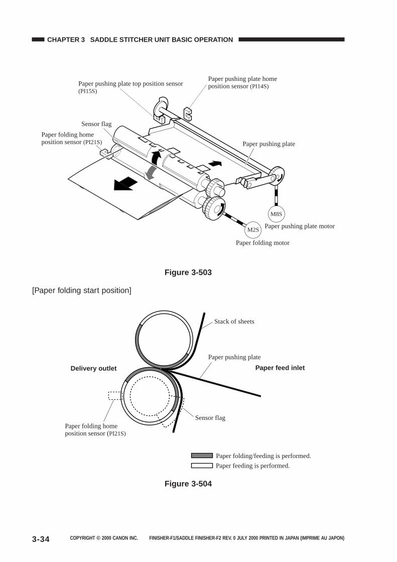
COPYRIGHT © 2000 CANON INC. FINISHER-F1/SADDLE FINISHER-F2 REV. 0 JULY 2000 PRINTED IN JAPAN (IMPRIME AU JAPON)3-34
CHAPTER 3 SADDLE STITCHER UNIT BASIC OPERATION
Sensor flag
Paper folding home position sensor (PI21S)
Paper pushing plate top position sensor(PI15S)
Paper pushing plate home position sensor (PI14S)
Paper pushing plate
Paper pushing plate motor
Paper folding motor
M2S
M8S
Figure 3-503
[Paper folding start position]
Paper folding/feeding is performed.
Paper feeding is performed.
Paper folding home position sensor (PI21S)
Sensor flag
Delivery outlet Paper feed inlet
Paper pushing plate
Stack of sheets
Figure 3-504
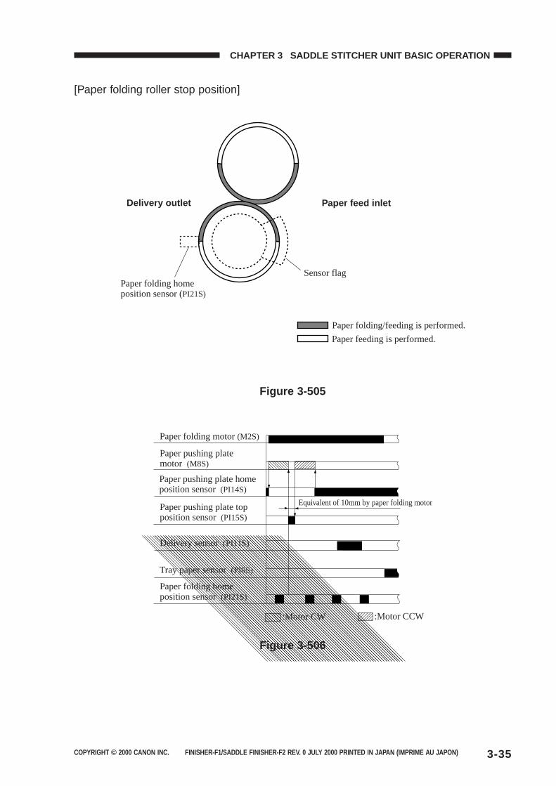
COPYRIGHT © 2000 CANON INC. FINISHER-F1/SADDLE FINISHER-F2 REV. 0 JULY 2000 PRINTED IN JAPAN (IMPRIME AU JAPON) 3-35
CHAPTER 3 SADDLE STITCHER UNIT BASIC OPERATION
[Paper folding roller stop position]
Paper folding/feeding is performed.
Paper feeding is performed.
Paper folding home position sensor (PI21S)
Sensor flag
Delivery outlet Paper feed inlet
Figure 3-505
Paper folding motor (M2S)
Paper pushing plate motor (M8S)
Paper pushing plate home position sensor (PI14S)
Paper pushing plate top position sensor (PI15S)
Delivery sensor (PI11S)
Tray paper sensor (PI6S)
:Motor CW :Motor CCW
Paper folding home position sensor (PI21S)
Equivalent of 10mm by paper folding motor
Figure 3-506
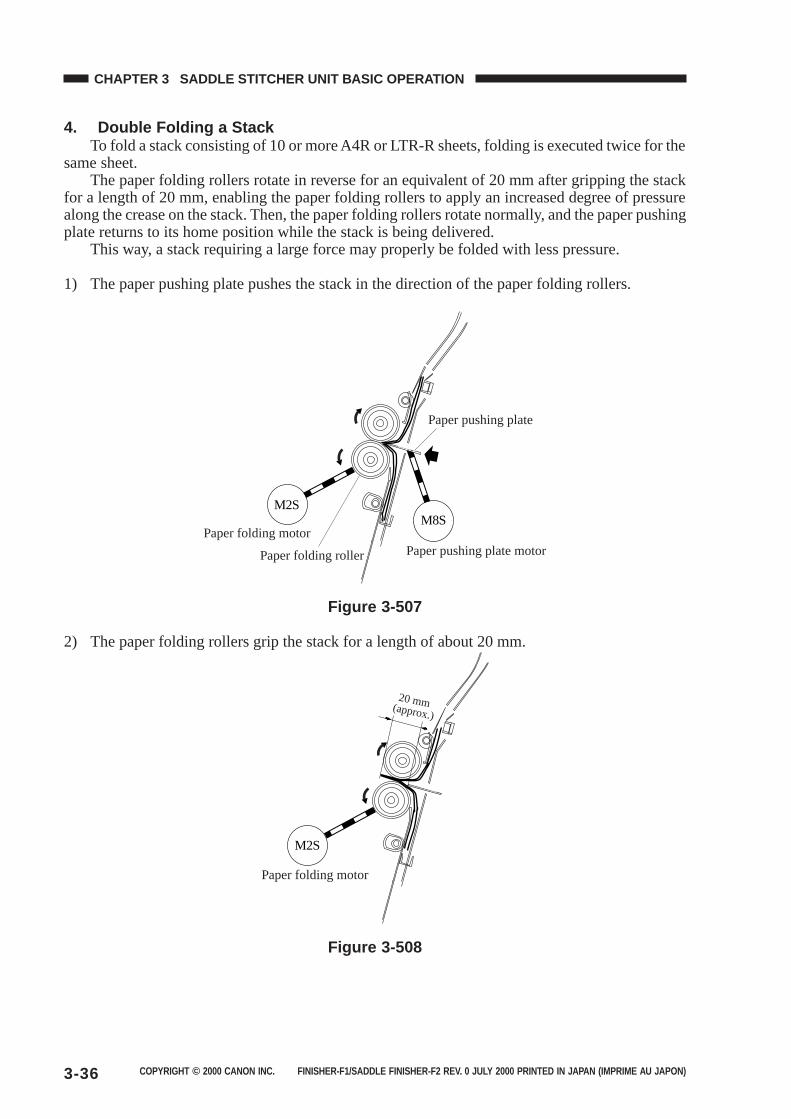
COPYRIGHT © 2000 CANON INC. FINISHER-F1/SADDLE FINISHER-F2 REV. 0 JULY 2000 PRINTED IN JAPAN (IMPRIME AU JAPON)3-36
CHAPTER 3 SADDLE STITCHER UNIT BASIC OPERATION
4. Double Folding a StackTo fold a stack consisting of 10 or more A4R or LTR-R sheets, folding is executed twice for the
same sheet.The paper folding rollers rotate in reverse for an equivalent of 20 mm after gripping the stack
for a length of 20 mm, enabling the paper folding rollers to apply an increased degree of pressurealong the crease on the stack. Then, the paper folding rollers rotate normally, and the paper pushingplate returns to its home position while the stack is being delivered.
This way, a stack requiring a large force may properly be folded with less pressure.
1) The paper pushing plate pushes the stack in the direction of the paper folding rollers.
M2S
Paper folding motorM8S
Paper pushing plate motor
Paper pushing plate
Paper folding roller
Figure 3-507
2) The paper folding rollers grip the stack for a length of about 20 mm.
M2S
Paper folding motor
20 mm (approx.)
Figure 3-508
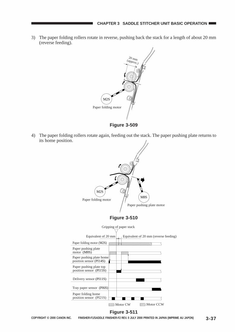
COPYRIGHT © 2000 CANON INC. FINISHER-F1/SADDLE FINISHER-F2 REV. 0 JULY 2000 PRINTED IN JAPAN (IMPRIME AU JAPON) 3-37
CHAPTER 3 SADDLE STITCHER UNIT BASIC OPERATION
3) The paper folding rollers rotate in reverse, pushing back the stack for a length of about 20 mm(reverse feeding).
M2S
Paper folding motor
20 mm (approx.)
Figure 3-509
4) The paper folding rollers rotate again, feeding out the stack. The paper pushing plate returns toits home position.
M2S
Paper folding motorM8S
Paper pushing plate motor
Figure 3-510
Paper folding motor (M2S)
Paper pushing plate motor (M8S)
Delivery sensor (PI11S)
Paper pushing plate top position sensor (PI15S)
Paper pushing plate home position sensor (PI14S)
Tray paper sensor (PI6S)
Equivalent of 20 mm Equivalent of 20 mm (reverse feeding)
Gripping of paper stack
:Motor CW :Motor CCW
Paper folding home position sensor (PI21S)
Figure 3-511
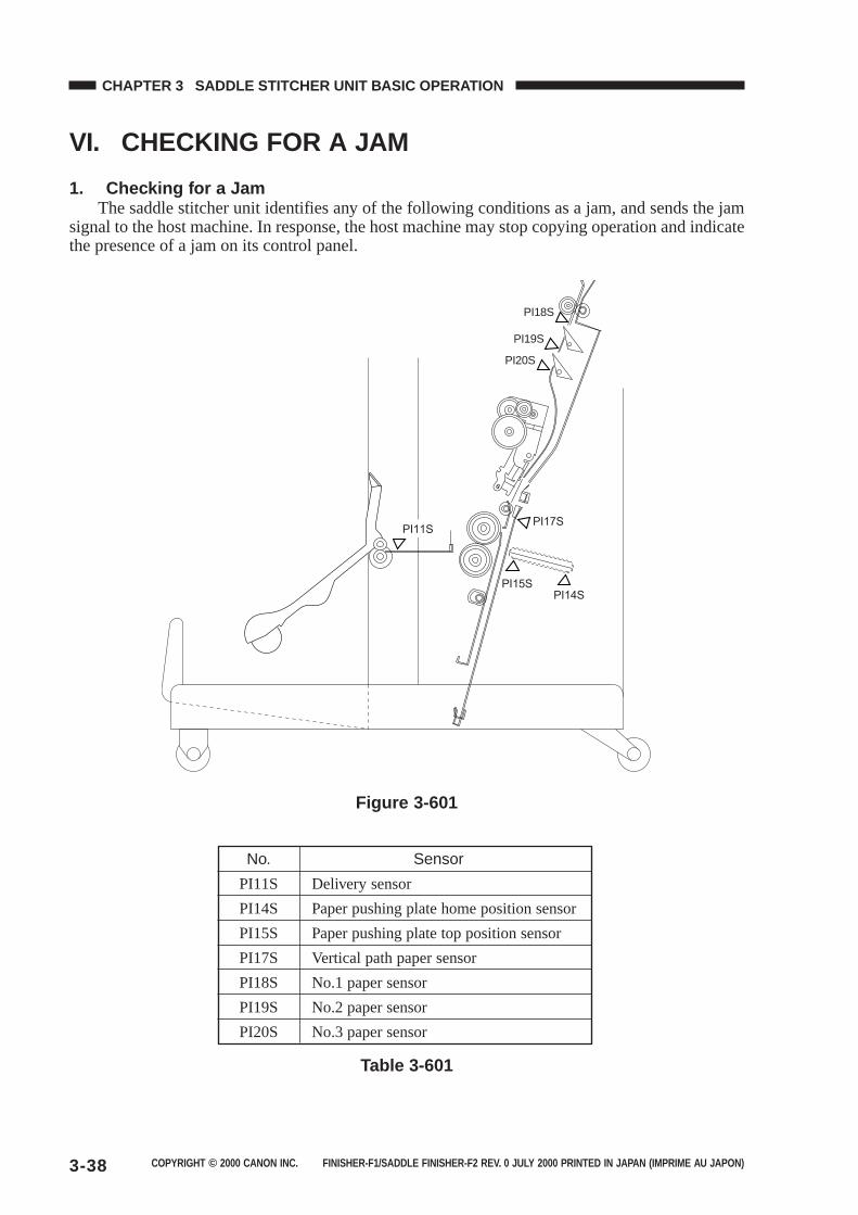
COPYRIGHT © 2000 CANON INC. FINISHER-F1/SADDLE FINISHER-F2 REV. 0 JULY 2000 PRINTED IN JAPAN (IMPRIME AU JAPON)3-38
CHAPTER 3 SADDLE STITCHER UNIT BASIC OPERATION
VI. CHECKING FOR A JAM
1. Checking for a JamThe saddle stitcher unit identifies any of the following conditions as a jam, and sends the jam
signal to the host machine. In response, the host machine may stop copying operation and indicatethe presence of a jam on its control panel.
PI18S
PI19S
PI20S
Figure 3-601
Table 3-601
No. Sensor
PI11S Delivery sensor
PI14S Paper pushing plate home position sensor
PI15S Paper pushing plate top position sensor
PI17S Vertical path paper sensor
PI18S No.1 paper sensor
PI19S No.2 paper sensor
PI20S No.3 paper sensor
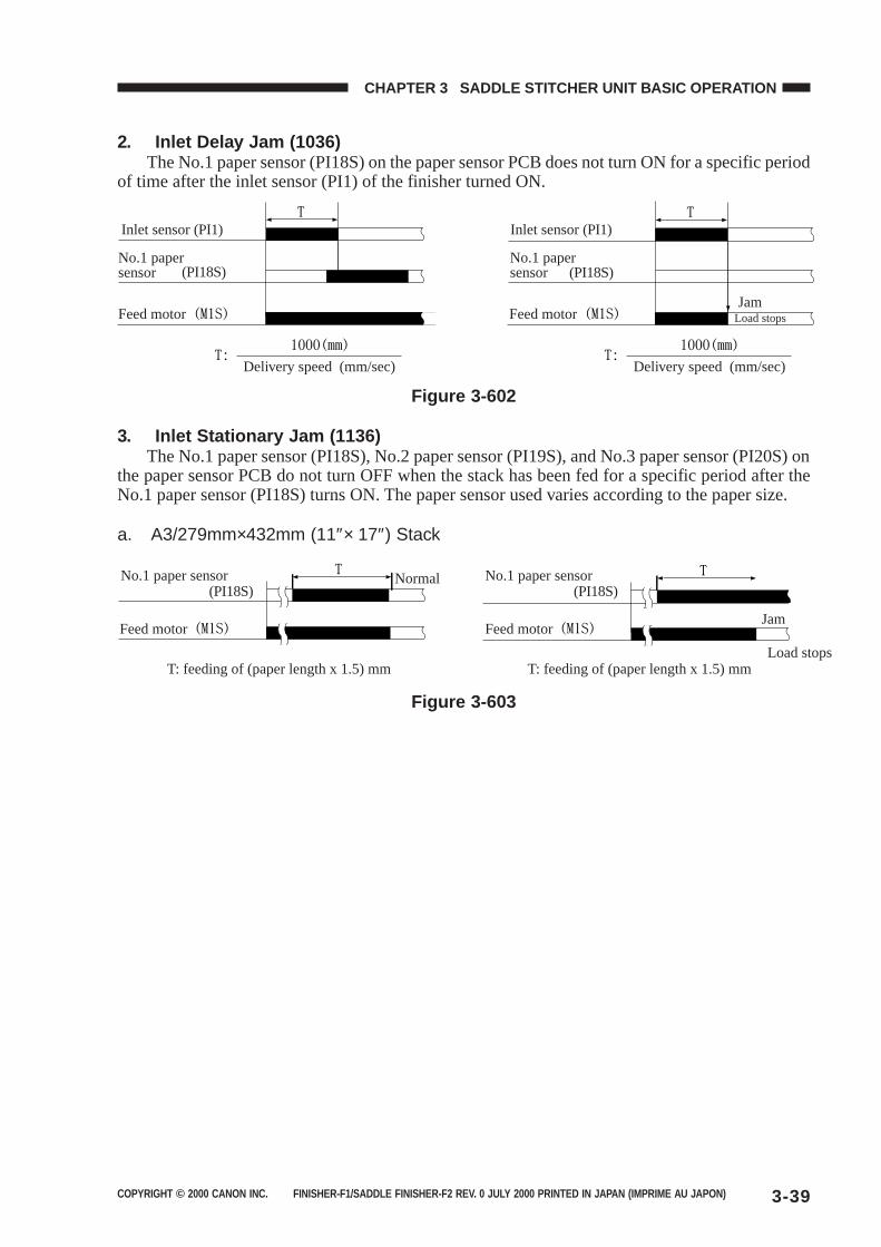
COPYRIGHT © 2000 CANON INC. FINISHER-F1/SADDLE FINISHER-F2 REV. 0 JULY 2000 PRINTED IN JAPAN (IMPRIME AU JAPON) 3-39
CHAPTER 3 SADDLE STITCHER UNIT BASIC OPERATION
2. Inlet Delay Jam (1036)The No.1 paper sensor (PI18S) on the paper sensor PCB does not turn ON for a specific period
of time after the inlet sensor (PI1) of the finisher turned ON.
Inlet sensor (PI1) Inlet sensor (PI1)
(PI18S) (PI18S)No.1 paper sensor
No.1 paper sensor
Feed motor Feed motor
Delivery speed (mm/sec) Delivery speed (mm/sec)
JamLoad stops
Figure 3-602
3. Inlet Stationary Jam (1136)The No.1 paper sensor (PI18S), No.2 paper sensor (PI19S), and No.3 paper sensor (PI20S) on
the paper sensor PCB do not turn OFF when the stack has been fed for a specific period after theNo.1 paper sensor (PI18S) turns ON. The paper sensor used varies according to the paper size.
a. A3/279mm×432mm (11″× 17″) Stack
(PI18S) (PI18S)No.1 paper sensor No.1 paper sensor
Feed motor Feed motor
Normal
Jam
Load stopsT: feeding of (paper length x 1.5) mm T: feeding of (paper length x 1.5) mm
Figure 3-603
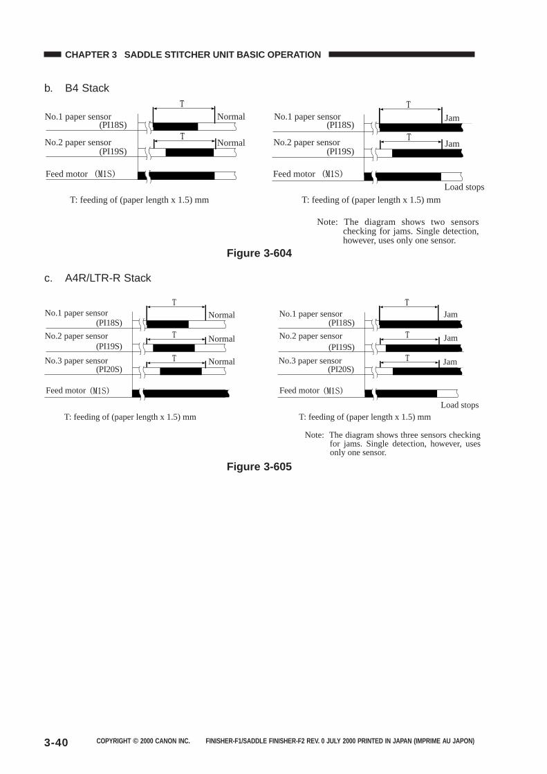
COPYRIGHT © 2000 CANON INC. FINISHER-F1/SADDLE FINISHER-F2 REV. 0 JULY 2000 PRINTED IN JAPAN (IMPRIME AU JAPON)3-40
CHAPTER 3 SADDLE STITCHER UNIT BASIC OPERATION
b. B4 Stack
(PI18S)
(PI19S)
(PI18S)
(PI19S)
No.1 paper sensor No.1 paper sensor
No.2 paper sensor No.2 paper sensor
Feed motor Feed motor
T: feeding of (paper length x 1.5) mm T: feeding of (paper length x 1.5) mm
Normal
Normal
Jam
Jam
Load stops
Note: The diagram shows two sensors checking for jams. Single detection, however, uses only one sensor.
Figure 3-604
c. A4R/LTR-R Stack
(PI18S)
(PI19S)
(PI20S)
(PI18S)
(PI19S)
Note: The diagram shows three sensors checking for jams. Single detection, however, uses only one sensor.
No.1 paper sensor No.1 paper sensor
No.2 paper sensor
No.3 paper sensor(PI20S)
No.3 paper sensor
No.2 paper sensor
Feed motorFeed motor
Jam
Jam
Jam
T: feeding of (paper length x 1.5) mm T: feeding of (paper length x 1.5) mmLoad stops
Normal
Normal
Normal
Figure 3-605
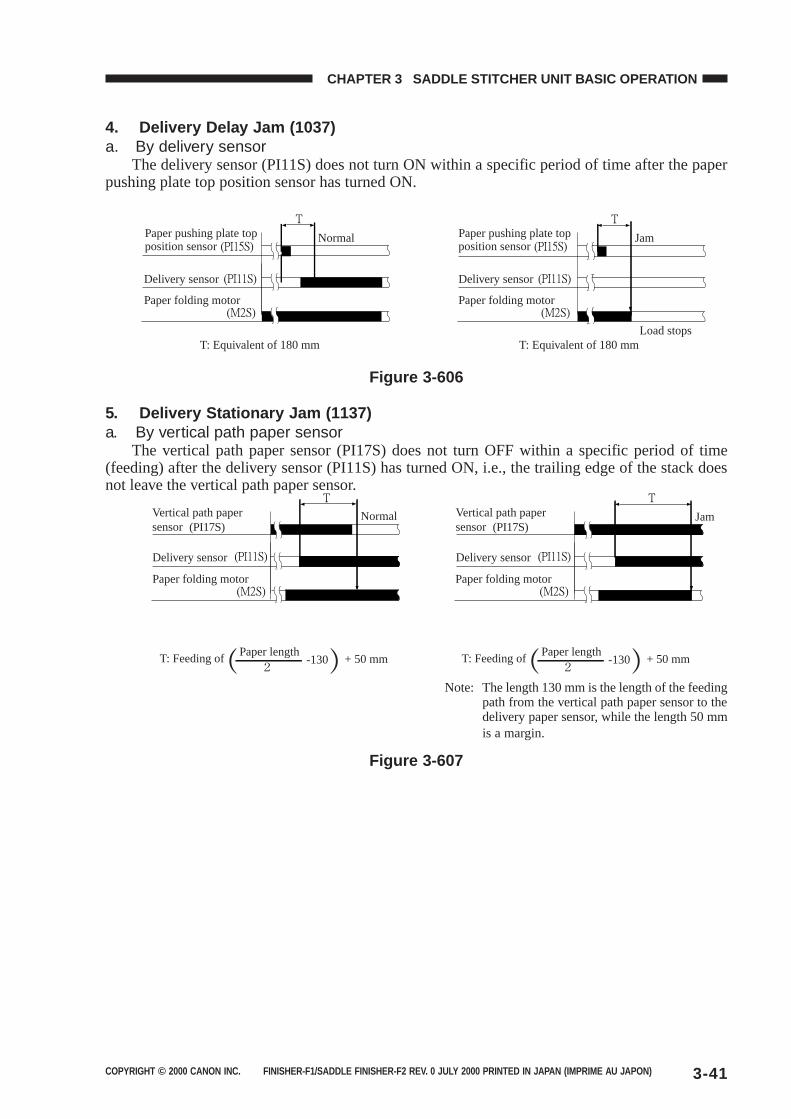
COPYRIGHT © 2000 CANON INC. FINISHER-F1/SADDLE FINISHER-F2 REV. 0 JULY 2000 PRINTED IN JAPAN (IMPRIME AU JAPON) 3-41
CHAPTER 3 SADDLE STITCHER UNIT BASIC OPERATION
4. Delivery Delay Jam (1037)a. By delivery sensor
The delivery sensor (PI11S) does not turn ON within a specific period of time after the paperpushing plate top position sensor has turned ON.
Paper pushing plate top position sensor
Paper pushing plate top position sensor
Delivery sensor Delivery sensor
Paper folding motor Paper folding motor
T: Equivalent of 180 mm T: Equivalent of 180 mmLoad stops
Normal Jam
Figure 3-606
5. Delivery Stationary Jam (1137)a. By vertical path paper sensor
The vertical path paper sensor (PI17S) does not turn OFF within a specific period of time(feeding) after the delivery sensor (PI11S) has turned ON, i.e., the trailing edge of the stack doesnot leave the vertical path paper sensor.
(PI17S)Vertical path paper sensor (PI17S)
Vertical path paper sensor
Normal Jam
Delivery sensor Delivery sensor
Paper folding motor Paper folding motor
T: Feeding ofPaper length
-130 + 50 mm T: Feeding ofPaper length
-130 + 50 mm
Note: The length 130 mm is the length of the feedingpath from the vertical path paper sensor to thedelivery paper sensor, while the length 50 mmis a margin.
Figure 3-607
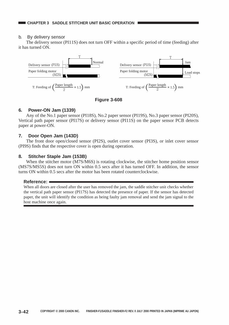
COPYRIGHT © 2000 CANON INC. FINISHER-F1/SADDLE FINISHER-F2 REV. 0 JULY 2000 PRINTED IN JAPAN (IMPRIME AU JAPON)3-42
CHAPTER 3 SADDLE STITCHER UNIT BASIC OPERATION
b. By delivery sensorThe delivery sensor (PI11S) does not turn OFF within a specific period of time (feeding) after
it has turned ON.
Delivery sensor Delivery sensorNormal Jam
Load stopsPaper folding motor Paper folding motor
T: Feeding ofPaper length
× 1.5 mm T: Feeding ofPaper length
× 1.5 mm
Figure 3-608
6. Power-ON Jam (1339)Any of the No.1 paper sensor (PI18S), No.2 paper sensor (PI19S), No.3 paper sensor (PI20S),
Vertical path paper sensor (PI17S) or delivery sensor (PI11S) on the paper sensor PCB detectspaper at power-ON.
7. Door Open Jam (143D)The front door open/closed sensor (PI2S), outlet cover sensor (PI3S), or inlet cover sensor
(PI9S) finds that the respective cover is open during operation.
8. Stitcher Staple Jam (153B)When the stitcher motor (M7S/M6S) is rotating clockwise, the stitcher home position sensor
(MS7S/MS5S) does not turn ON within 0.5 secs after it has turned OFF. In addition, the sensorturns ON within 0.5 secs after the motor has been rotated counterclockwise.
Reference:When all doors are closed after the user has removed the jam, the saddle stitcher unit checks whetherthe vertical path paper sensor (PI17S) has detected the presence of paper. If the sensor has detectedpaper, the unit will identify the condition as being faulty jam removal and send the jam signal to thehost machine once again.
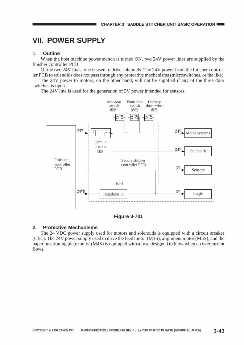
COPYRIGHT © 2000 CANON INC. FINISHER-F1/SADDLE FINISHER-F2 REV. 0 JULY 2000 PRINTED IN JAPAN (IMPRIME AU JAPON) 3-43
CHAPTER 3 SADDLE STITCHER UNIT BASIC OPERATION
VII. POWER SUPPLY
1. OutlineWhen the host machine power switch is turned ON, two 24V power lines are supplied by the
finisher controller PCB.Of the two 24V lines, one is used to drive solenoids. The 24V power from the finisher control-
ler PCB to solenoids does not pass through any protective mechanisms (microswitches, or the like).The 24V power to motors, on the other hand, will not be supplied if any of the three door
switches is open.The 24V line is used for the generation of 5V power intended for sensors.
Inlet door switch
Front door switch
Delivery door switch
Finisher controller PCB
Circuit breaker
Saddle stitcher controller PCB
Motor systems
Solenoids
Sensors
LogicRegulator IC
Figure 3-701
2. Protective MechanismsThe 24 VDC power supply used for motors and solenoids is equipped with a circuit breaker
(CB1). The 24V power supply used to drive the feed motor (M1S), alignment motor (M5S), and thepaper positioning plate motor (M4S) is equipped with a fuse designed to blow when an overcurrentflows.

COPYRIGHT © 2000 CANON INC. FINISHER-C1/SADDLE FINISHER-C2 REV. 0 JULY 2000 PRINTED IN JAPAN (IMPRIME AU JAPON)
CHAPTER 4
PUNCHER UNIT (OPTION)BASIC OPERATION
I. BASIC OPERATION...................4-1A. Outline .................................4-1B. Inputs to and Outputs from
Punch Driver PCB ................4-2II. PUNCH OPERATION .................4-5
A. Outline ..................................4-5B. PUNCH OPERATION...........4-7C. Horizontal Registration
Operation ........................... 4-11III. POWER SUPPLY SYSTEM .... 4-14
1. This chapter discusses the purpose and role of each of the puncher unit’s functions, and theprinciples of operation used for the puncher unit mechanical and electrical systems. It alsoexplains the timing at which these systems are operated.
The symbol in drawings indicates transmission of mechanical drive, and signals markedby together with the signal name indicates the flow of electrical signals.
2. In descriptions of digital circuits on the puncher unit, “1” indicates a high signal voltage level,while “0” indicates a low signal voltage level. Voltage values differ according to circuit.
Descriptions in this chapter also assume that PCBs will not be repaired at user sites. For thisreason, descriptions of circuits on PCBs is limited to block diagrams. Two types of block dia-grams are provided for separate functions: diagrams indicating details from sensors up to inputsections of major PCBs, and diagrams indicating details from the output sections of majorPCBs up the loads.

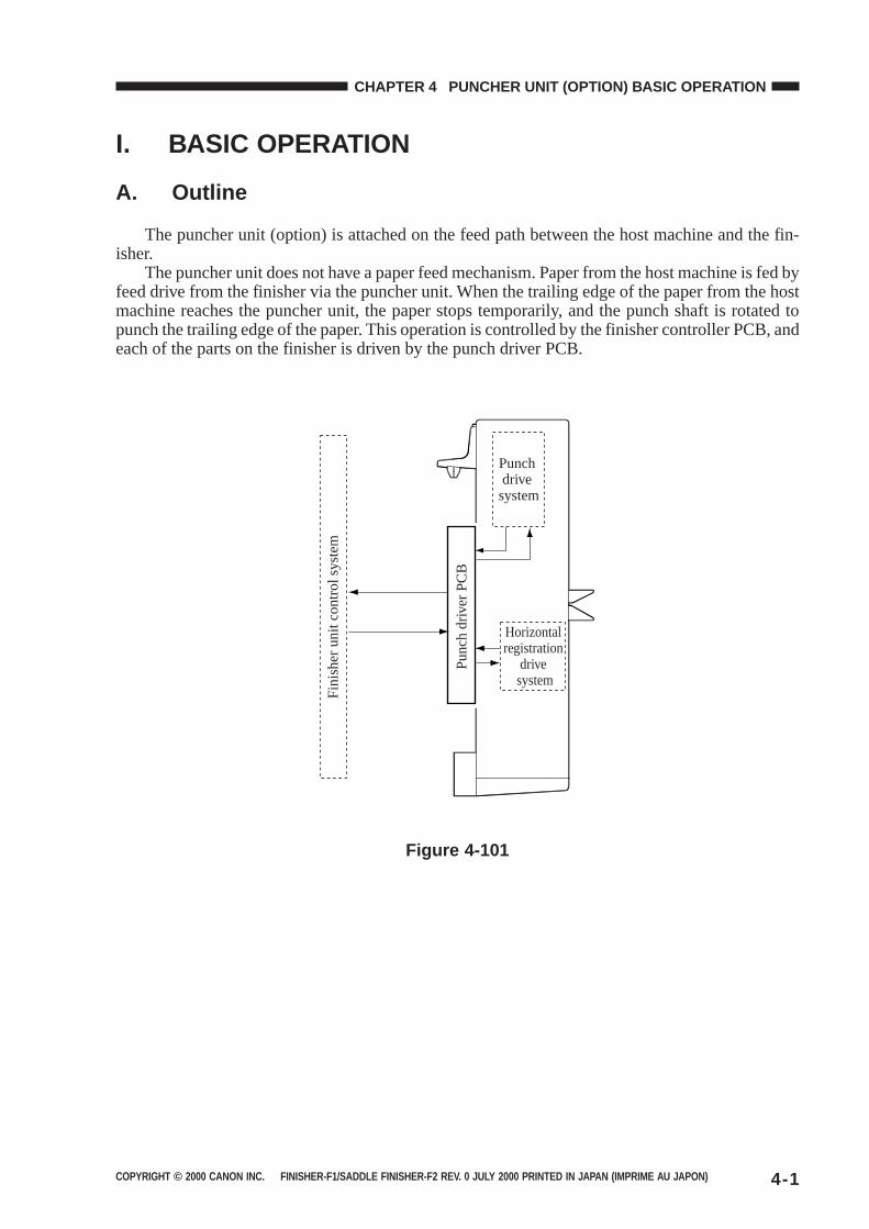
COPYRIGHT © 2000 CANON INC. FINISHER-F1/SADDLE FINISHER-F2 REV. 0 JULY 2000 PRINTED IN JAPAN (IMPRIME AU JAPON) 4-1
CHAPTER 4 PUNCHER UNIT (OPTION) BASIC OPERATION
I. BASIC OPERATION
A. Outline
The puncher unit (option) is attached on the feed path between the host machine and the fin-isher.
The puncher unit does not have a paper feed mechanism. Paper from the host machine is fed byfeed drive from the finisher via the puncher unit. When the trailing edge of the paper from the hostmachine reaches the puncher unit, the paper stops temporarily, and the punch shaft is rotated topunch the trailing edge of the paper. This operation is controlled by the finisher controller PCB, andeach of the parts on the finisher is driven by the punch driver PCB.
Fin
ishe
r un
it co
ntro
l sys
tem
Pun
ch d
river
PC
BPunch drive system
Horizontal registration
drive system
Figure 4-101
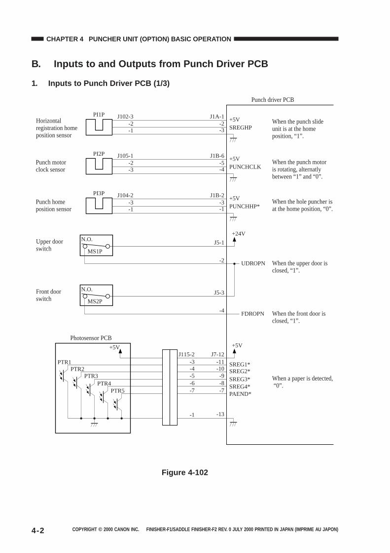
COPYRIGHT © 2000 CANON INC. FINISHER-F1/SADDLE FINISHER-F2 REV. 0 JULY 2000 PRINTED IN JAPAN (IMPRIME AU JAPON)4-2
CHAPTER 4 PUNCHER UNIT (OPTION) BASIC OPERATION
B. Inputs to and Outputs from Punch Driver PCB
1. Inputs to Punch Driver PCB (1/3)
Punch driver PCB
PI1P
-2J102-3 +5V
SREGHP-1-2
J1A-1
-3
SREG1*SREG2*SREG3*
-9-10-11
J7-12
-13
-5
SREG4*-8-6
PAEND*-7-7
-4-3
J115-2
-1
Horizontal registration home position sensor
PI3P
MS1P
MS2P
-3J104-2 +5V
PUNCHHP*-1-3
J1B-2
-1
Upper door switch
N.O.+24V
+5V+5V
PTR1PTR2
PTR3PTR4
PTR5
UDROPN
FDROPN
When the upper door is closed, “1”.
When the hole puncher is at the home position, “0”.
When the punch slide unit is at the home position, “1”.
When the front door is closed, “1”.
When a paper is detected, “0”.
-2
J5-1
Front door switch
Photosensor PCB
N.O.
-4
J5-3
Punch home position sensor
PI2P
-2J105-1 +5V
PUNCHCLK-3-5
J1B-6
-4When the punch motor is rotating, alternatly between “1” and “0”.
Punch motor clock sensor
Figure 4-102
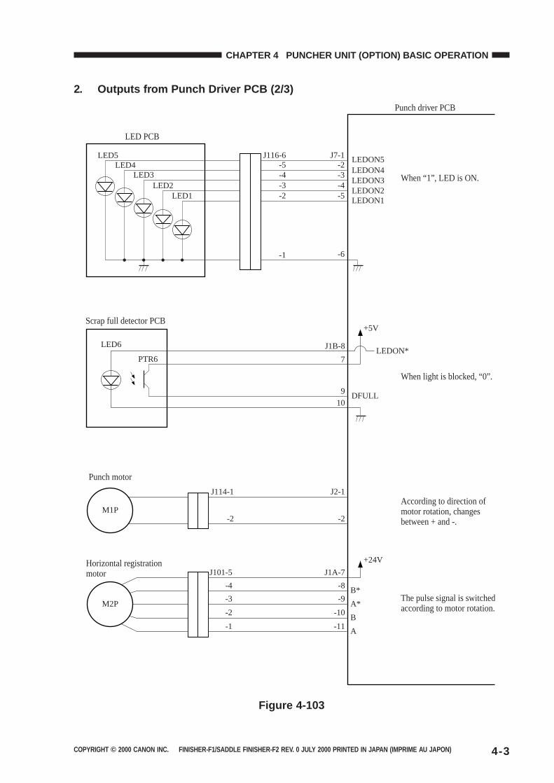
COPYRIGHT © 2000 CANON INC. FINISHER-F1/SADDLE FINISHER-F2 REV. 0 JULY 2000 PRINTED IN JAPAN (IMPRIME AU JAPON) 4-3
CHAPTER 4 PUNCHER UNIT (OPTION) BASIC OPERATION
2. Outputs from Punch Driver PCB (2/3)
Punch driver PCB
M2P
Horizontal registration motor
+24V
+5V
DFULL
LEDON*
According to direction of motor rotation, changes between + and -.
When light is blocked, “0”.
When “1”, LED is ON.
The pulse signal is switched according to motor rotation.
B*
A*
B
A
J1A-7
-8
-9
-10
-11
J101-5
-4
-3
-2
-1
M1P
Punch motor
Scrap full detector PCB
J2-1
J1B-8
7
9
10
-2
J114-1
-2
LEDON5LEDON4LEDON3LEDON2LEDON1
-3-2
J7-1
-6
-4-4-3-5-2
-5J116-6
-1
LED5LED4
LED3LED2
LED1
LED PCB
PTR6
LED6
Figure 4-103
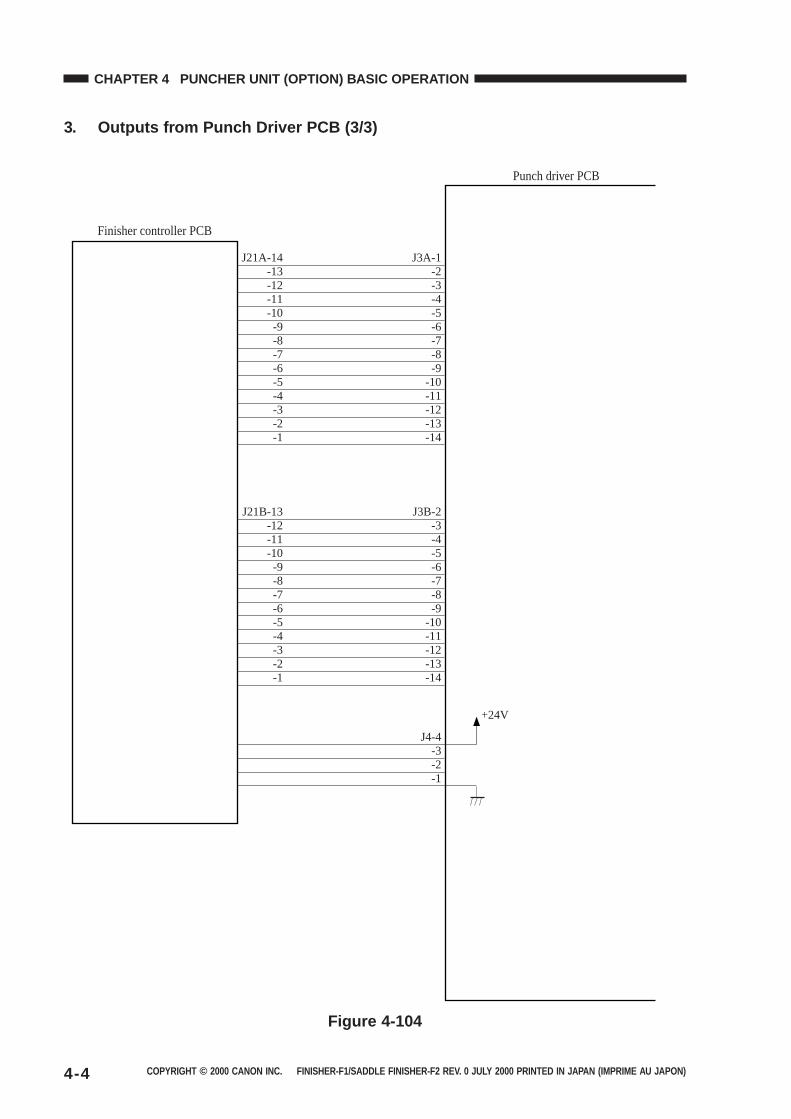
COPYRIGHT © 2000 CANON INC. FINISHER-F1/SADDLE FINISHER-F2 REV. 0 JULY 2000 PRINTED IN JAPAN (IMPRIME AU JAPON)4-4
CHAPTER 4 PUNCHER UNIT (OPTION) BASIC OPERATION
3. Outputs from Punch Driver PCB (3/3)
Punch driver PCB
+24V
J3A-1J21A-14-2-13-3-12-4
J4-4-3-2-1
-11-5-10-6-9-7-8-8-7-9-6
-10-5-11-4-12-3-13-2-14-1
J3B-2J21B-13-3-12-4-11-5-10-6-9-7-8-8-7-9-6
-10-5-11-4-12-3-13-2-14-1
Finisher controller PCB
Figure 4-104
COPYRIGHT © 2000 CANON INC. FINISHER-F1/SADDLE FINISHER-F2 REV. 0 JULY 2000 PRINTED IN JAPAN (IMPRIME AU JAPON) 4-5
CHAPTER 4 PUNCHER UNIT (OPTION) BASIC OPERATION
II. PUNCH OPERATION
A. Outline
The puncher unit is located on the feed path between the host machine and the finisher, andsuccessively punches holes when the paper stops temporarily. When the trailing edge of the paperreaches the puncher unit, the inlet roller of the finisher unit temporarily stops the paper and holesare punched on the trailing edge of the paper.
The puncher unit consists of a die and hole puncher (punch blade).The hole puncher is driven by the punch motor (M1P). The hole puncher is attached to the
eccentric cam of the punch shaft, and rotary action of the punch shaft is converted to reciprocalmotion to perform punching.
Punch motor (M1P) is a DC motor. The home position of the punch shaft is detected by punchhome position sensor (PI3P). To stop the DC punch motor accurately at its home position, thepunch motor clock sensor (PI2P) counts a predetermined number of clock pulses to stop the punchmotor. A single punch operation is performed by rotating the punch shaft 180° from its homeposition.
Five light sensors (photosensor PCB) are located at the upper side of the inlet paper feed path ofthe puncher unit and a set of five LEDs (LED PCB) are located at the lower side. These sensors andLEDs function as five sensors. The frontmost sensor (LED5, PTR5) are the trailing edge sensor andare used for detecting the trailing edge of the paper. The remaining sensors (LED1 to LED4, PTR1to PTR4) are horizontal registration sensors, and are used for detecting the inner position of thepaper for determining the hole punching position.
The punch motor, puncher unit and above sensors comprise the punch slide unit. This unitmoves backwards and forwards according to the size of the paper. Backward and forward move-ment is driven by the horizontal registration motor (M2P). The home position of the punch slideunit is detected by the horizontal registration home position sensor (PI1P). The horizontal registra-tion motor (M2P) is a 2-phase stepping motor.
The punch motor and horizontal registration motor is driven by the punch driver PCB accord-ing to control signals from the finisher controller PCB.
Punch scraps caused by punching are stored in the punched scrap container. Scrap full detec-tion is performed by a reflective sensor (LED6 and PTR6 on the scrap full detector PCB unit).
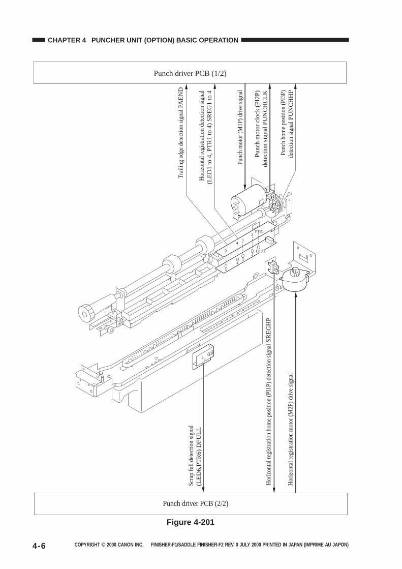
COPYRIGHT © 2000 CANON INC. FINISHER-F1/SADDLE FINISHER-F2 REV. 0 JULY 2000 PRINTED IN JAPAN (IMPRIME AU JAPON)4-6
CHAPTER 4 PUNCHER UNIT (OPTION) BASIC OPERATION
Hor
izon
tal r
egis
tratio
n m
otor
(M2P
) driv
e si
gnal
Pun
ch m
otor
(M1P
) driv
e si
gnal
Punch driver PCB (1/2)
Scr
ap fu
ll de
tect
ion
sign
al(L
ED
6,P
TR
6) D
FU
LL
Trai
ling
edge
det
ectio
n si
gnal P
AE
ND
Hor
izon
tal r
egis
tratio
n de
tect
ion
sign
al(L
ED
1 to
4, P
TR
1 to
4)
SR
EG
1 to
4
Pun
ch h
ome
posi
tion
(PI3
P)
dete
ctio
n si
gnal P
UN
CH
HP
Hor
izon
tal r
egis
tratio
n ho
me
posi
tion
(PI1
P) d
etec
tion
sign
al S
RE
GH
P
Punch driver PCB (2/2)
Pun
ch m
otor
clo
ck (
PI2
P)
dete
ctio
n si
gnal
PU
NC
HC
LK
PTR1
LED12
34
5
2
34
5
Figure 4-201
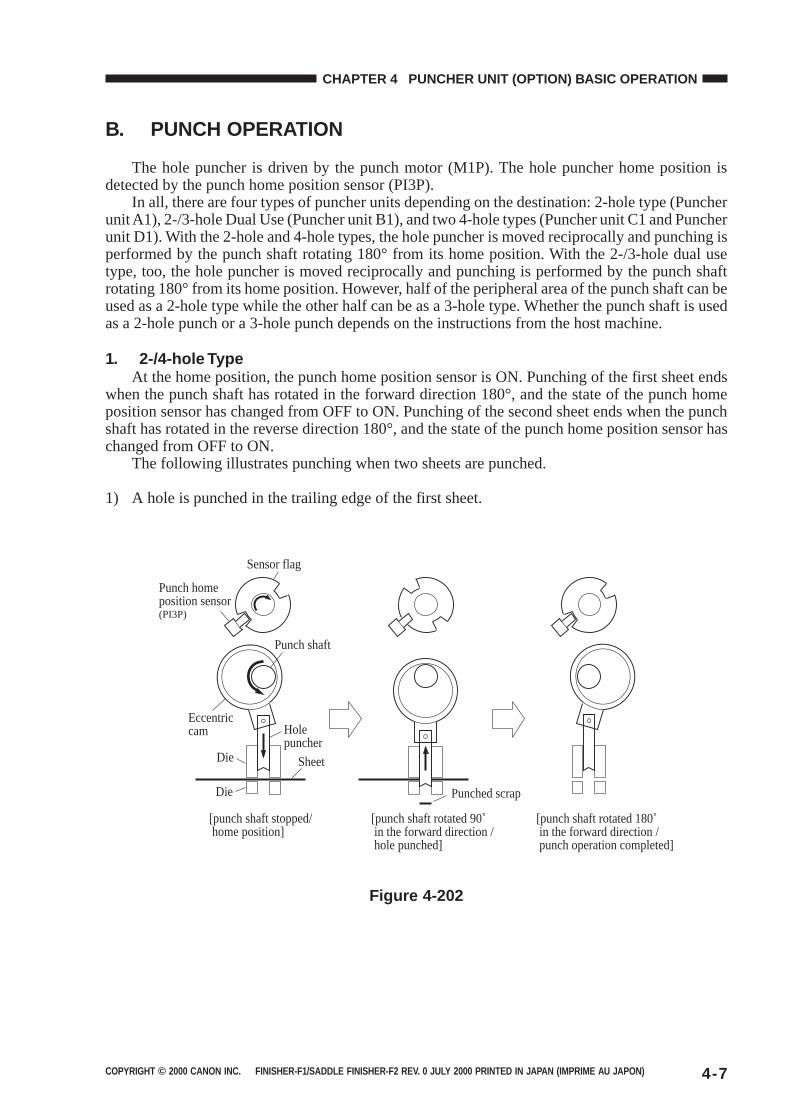
COPYRIGHT © 2000 CANON INC. FINISHER-F1/SADDLE FINISHER-F2 REV. 0 JULY 2000 PRINTED IN JAPAN (IMPRIME AU JAPON) 4-7
CHAPTER 4 PUNCHER UNIT (OPTION) BASIC OPERATION
B. PUNCH OPERATION
The hole puncher is driven by the punch motor (M1P). The hole puncher home position isdetected by the punch home position sensor (PI3P).
In all, there are four types of puncher units depending on the destination: 2-hole type (Puncherunit A1), 2-/3-hole Dual Use (Puncher unit B1), and two 4-hole types (Puncher unit C1 and Puncherunit D1). With the 2-hole and 4-hole types, the hole puncher is moved reciprocally and punching isperformed by the punch shaft rotating 180° from its home position. With the 2-/3-hole dual usetype, too, the hole puncher is moved reciprocally and punching is performed by the punch shaftrotating 180° from its home position. However, half of the peripheral area of the punch shaft can beused as a 2-hole type while the other half can be as a 3-hole type. Whether the punch shaft is usedas a 2-hole punch or a 3-hole punch depends on the instructions from the host machine.
1. 2-/4-hole TypeAt the home position, the punch home position sensor is ON. Punching of the first sheet ends
when the punch shaft has rotated in the forward direction 180°, and the state of the punch homeposition sensor has changed from OFF to ON. Punching of the second sheet ends when the punchshaft has rotated in the reverse direction 180°, and the state of the punch home position sensor haschanged from OFF to ON.
The following illustrates punching when two sheets are punched.
1) A hole is punched in the trailing edge of the first sheet.
[punch shaft stopped/ home position]
[punch shaft rotated 90˚ in the forward direction / hole punched]
[punch shaft rotated 180˚ in the forward direction / punch operation completed]
Sensor flag
Punch home position sensor(PI3P)
Punch shaft
Eccentric cam Hole
puncherDie
Die
Sheet
Punched scrap
Figure 4-202
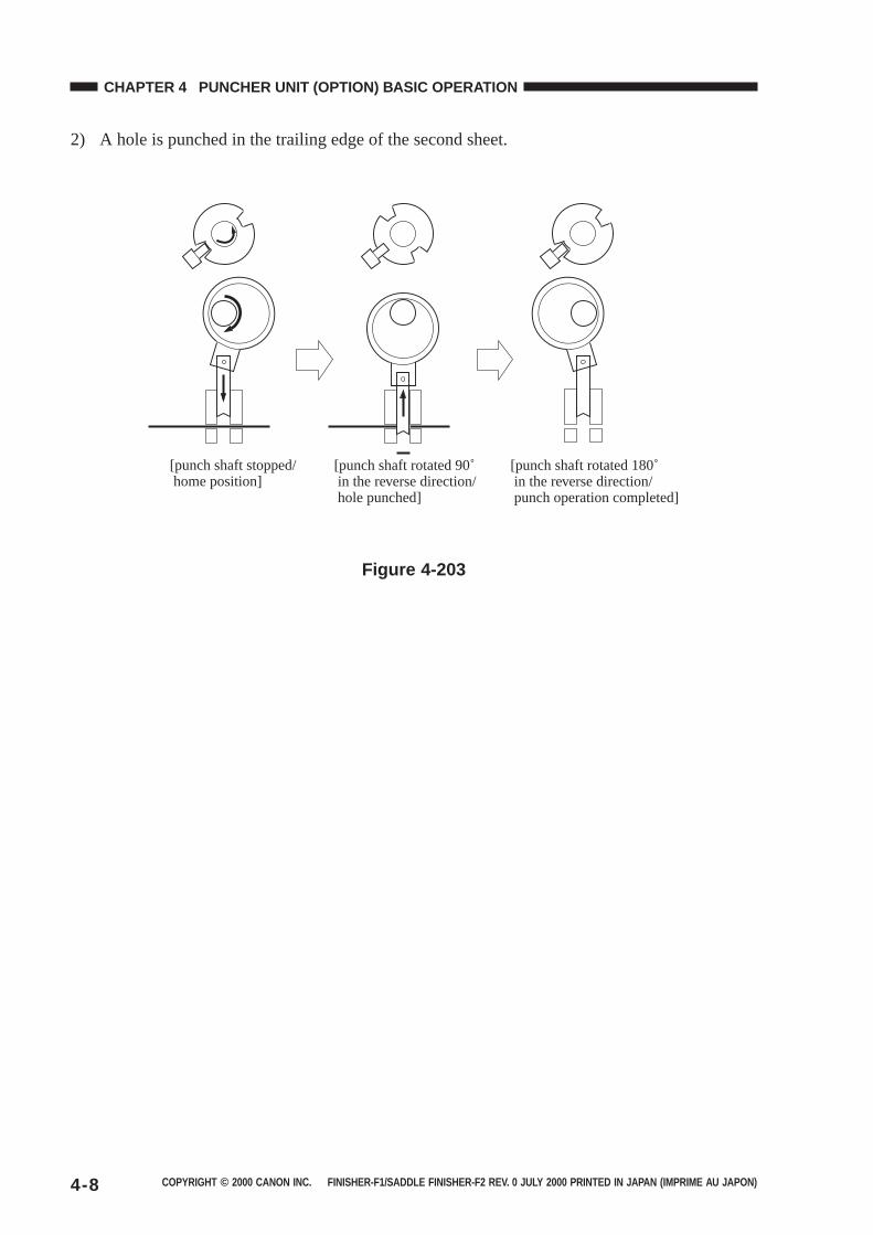
COPYRIGHT © 2000 CANON INC. FINISHER-F1/SADDLE FINISHER-F2 REV. 0 JULY 2000 PRINTED IN JAPAN (IMPRIME AU JAPON)4-8
CHAPTER 4 PUNCHER UNIT (OPTION) BASIC OPERATION
2) A hole is punched in the trailing edge of the second sheet.
[punch shaft stopped/ home position]
[punch shaft rotated 90˚ in the reverse direction/ hole punched]
[punch shaft rotated 180˚ in the reverse direction/ punch operation completed]
Figure 4-203
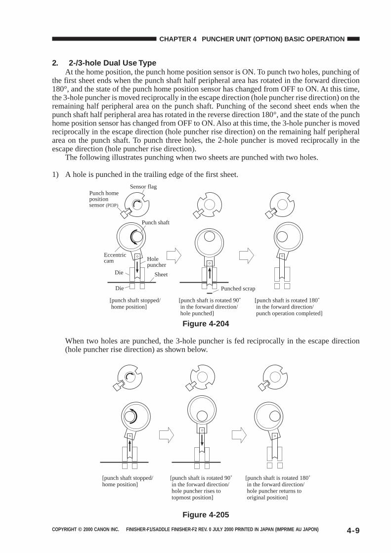
COPYRIGHT © 2000 CANON INC. FINISHER-F1/SADDLE FINISHER-F2 REV. 0 JULY 2000 PRINTED IN JAPAN (IMPRIME AU JAPON) 4-9
CHAPTER 4 PUNCHER UNIT (OPTION) BASIC OPERATION
2. 2-/3-hole Dual Use TypeAt the home position, the punch home position sensor is ON. To punch two holes, punching of
the first sheet ends when the punch shaft half peripheral area has rotated in the forward direction180°, and the state of the punch home position sensor has changed from OFF to ON. At this time,the 3-hole puncher is moved reciprocally in the escape direction (hole puncher rise direction) on theremaining half peripheral area on the punch shaft. Punching of the second sheet ends when thepunch shaft half peripheral area has rotated in the reverse direction 180°, and the state of the punchhome position sensor has changed from OFF to ON. Also at this time, the 3-hole puncher is movedreciprocally in the escape direction (hole puncher rise direction) on the remaining half peripheralarea on the punch shaft. To punch three holes, the 2-hole puncher is moved reciprocally in theescape direction (hole puncher rise direction).
The following illustrates punching when two sheets are punched with two holes.
1) A hole is punched in the trailing edge of the first sheet.
[punch shaft stopped/ home position]
[punch shaft is rotated 90˚ in the forward direction/ hole punched]
[punch shaft is rotated 180˚ in the forward direction/ punch operation completed]
Sensor flagPunch home position sensor (PI3P)
Punch shaft
Eccentric cam Hole
puncherDie
Die
Sheet
Punched scrap
Figure 4-204
When two holes are punched, the 3-hole puncher is fed reciprocally in the escape direction(hole puncher rise direction) as shown below.
[punch shaft stopped/home position]
[punch shaft is rotated 90˚ in the forward direction/ hole puncher rises to topmost position]
[punch shaft is rotated 180˚ in the forward direction/ hole puncher returns to original position]
Figure 4-205
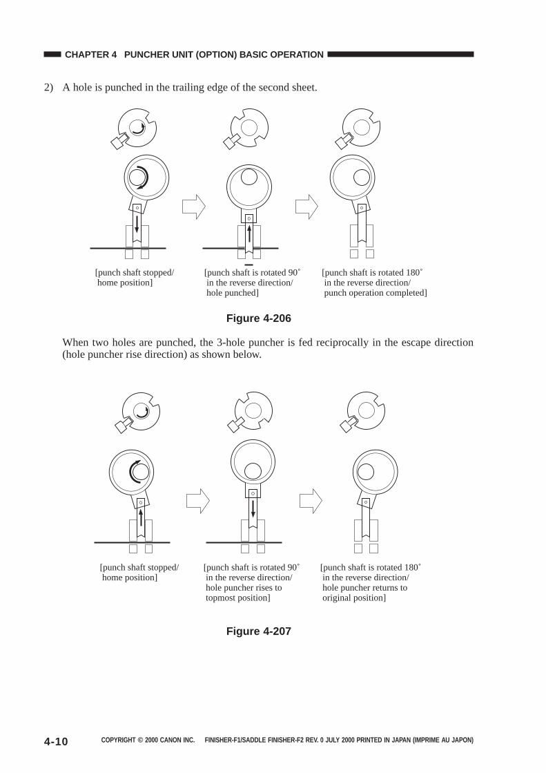
COPYRIGHT © 2000 CANON INC. FINISHER-F1/SADDLE FINISHER-F2 REV. 0 JULY 2000 PRINTED IN JAPAN (IMPRIME AU JAPON)4-10
CHAPTER 4 PUNCHER UNIT (OPTION) BASIC OPERATION
2) A hole is punched in the trailing edge of the second sheet.
[punch shaft stopped/ home position]
[punch shaft is rotated 90˚ in the reverse direction/ hole punched]
[punch shaft is rotated 180˚ in the reverse direction/ punch operation completed]
Figure 4-206
When two holes are punched, the 3-hole puncher is fed reciprocally in the escape direction(hole puncher rise direction) as shown below.
[punch shaft is rotated 90˚ in the reverse direction/ hole puncher rises to topmost position]
[punch shaft is rotated 180˚ in the reverse direction/ hole puncher returns to original position]
[punch shaft stopped/ home position]
Figure 4-207
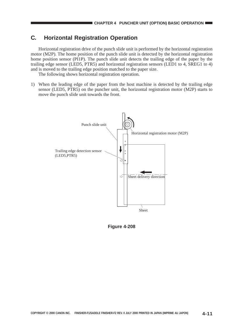
COPYRIGHT © 2000 CANON INC. FINISHER-F1/SADDLE FINISHER-F2 REV. 0 JULY 2000 PRINTED IN JAPAN (IMPRIME AU JAPON) 4-11
CHAPTER 4 PUNCHER UNIT (OPTION) BASIC OPERATION
C. Horizontal Registration Operation
Horizontal registration drive of the punch slide unit is performed by the horizontal registrationmotor (M2P). The home position of the punch slide unit is detected by the horizontal registrationhome position sensor (PI1P). The punch slide unit detects the trailing edge of the paper by thetrailing edge sensor (LED5, PTR5) and horizontal registration sensors (LED1 to 4, SREG1 to 4)and is moved to the trailing edge position matched to the paper size.
The following shows horizontal registration operation.
1) When the leading edge of the paper from the host machine is detected by the trailing edgesensor (LED5, PTR5) on the puncher unit, the horizontal registration motor (M2P) starts tomove the punch slide unit towards the front.
Horizontal registration motor (M2P)
Sheet delivery direction
Punch slide unit
Trailing edge detection sensor(LED5,PTR5)
Sheet
Figure 4-208
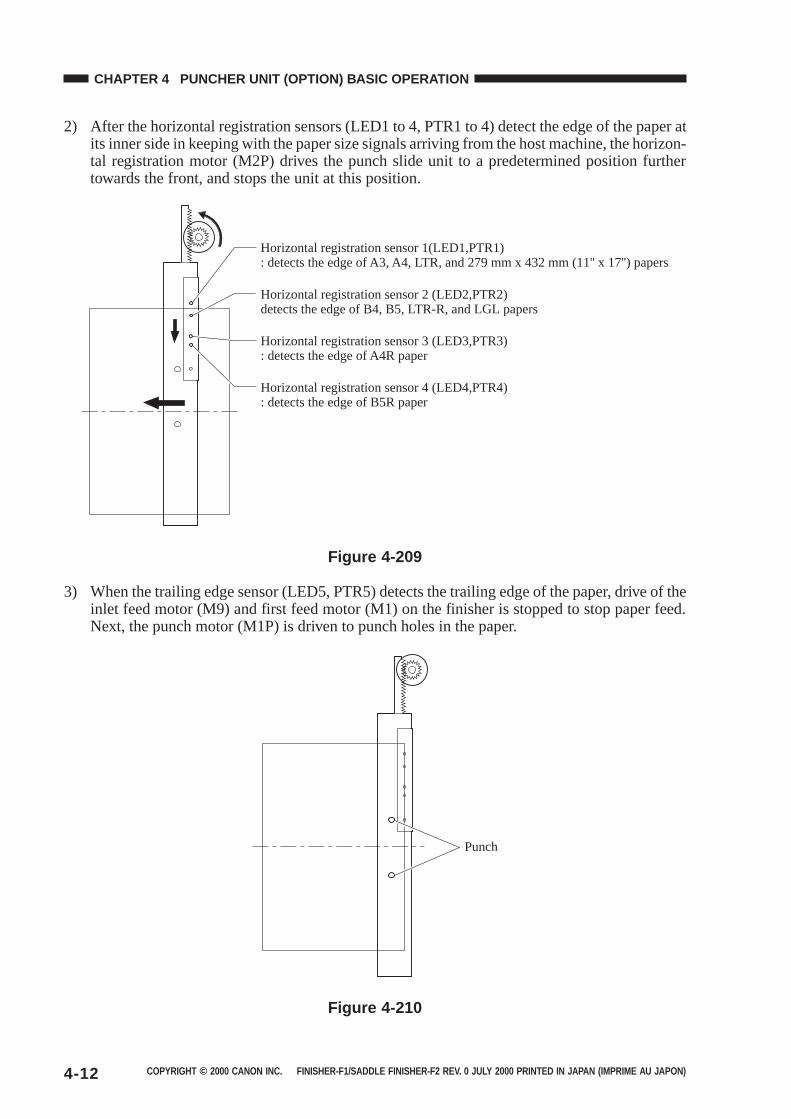
COPYRIGHT © 2000 CANON INC. FINISHER-F1/SADDLE FINISHER-F2 REV. 0 JULY 2000 PRINTED IN JAPAN (IMPRIME AU JAPON)4-12
CHAPTER 4 PUNCHER UNIT (OPTION) BASIC OPERATION
2) After the horizontal registration sensors (LED1 to 4, PTR1 to 4) detect the edge of the paper atits inner side in keeping with the paper size signals arriving from the host machine, the horizon-tal registration motor (M2P) drives the punch slide unit to a predetermined position furthertowards the front, and stops the unit at this position.
Horizontal registration sensor 1(LED1,PTR1): detects the edge of A3, A4, LTR, and 279 mm x 432 mm (11'' x 17'') papers
Horizontal registration sensor 2 (LED2,PTR2)detects the edge of B4, B5, LTR-R, and LGL papers
Horizontal registration sensor 3 (LED3,PTR3): detects the edge of A4R paper
Horizontal registration sensor 4 (LED4,PTR4): detects the edge of B5R paper
Figure 4-209
3) When the trailing edge sensor (LED5, PTR5) detects the trailing edge of the paper, drive of theinlet feed motor (M9) and first feed motor (M1) on the finisher is stopped to stop paper feed.Next, the punch motor (M1P) is driven to punch holes in the paper.
Punch
Figure 4-210
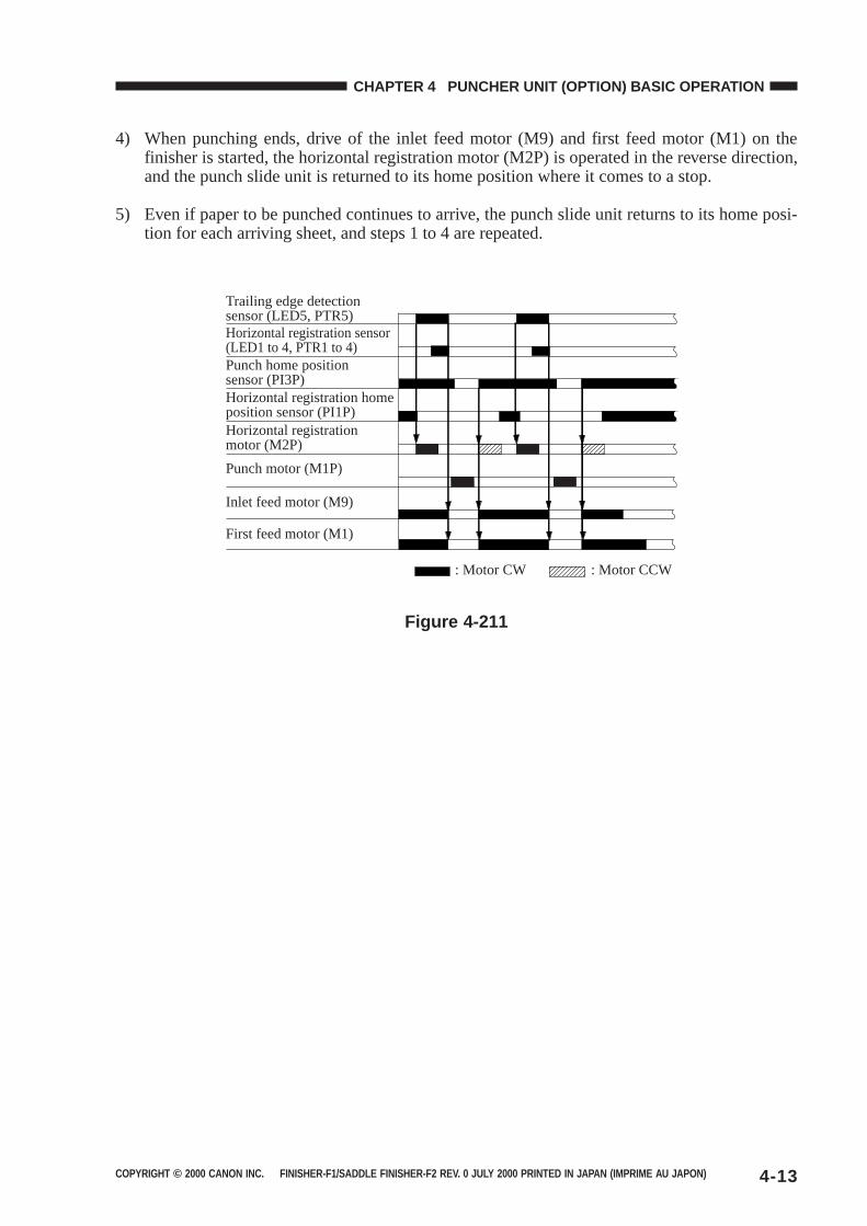
COPYRIGHT © 2000 CANON INC. FINISHER-F1/SADDLE FINISHER-F2 REV. 0 JULY 2000 PRINTED IN JAPAN (IMPRIME AU JAPON) 4-13
CHAPTER 4 PUNCHER UNIT (OPTION) BASIC OPERATION
4) When punching ends, drive of the inlet feed motor (M9) and first feed motor (M1) on thefinisher is started, the horizontal registration motor (M2P) is operated in the reverse direction,and the punch slide unit is returned to its home position where it comes to a stop.
5) Even if paper to be punched continues to arrive, the punch slide unit returns to its home posi-tion for each arriving sheet, and steps 1 to 4 are repeated.
Punch motor (M1P)
Inlet feed motor (M9)
First feed motor (M1)
Trailing edge detection sensor (LED5, PTR5)Horizontal registration sensor (LED1 to 4, PTR1 to 4)
: Motor CW : Motor CCW
Horizontal registration motor (M2P)
Horizontal registration home position sensor (PI1P)
Punch home position sensor (PI3P)
Figure 4-211
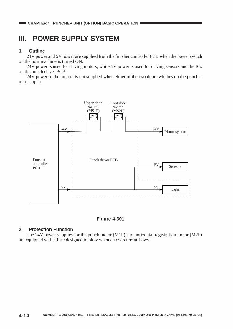
COPYRIGHT © 2000 CANON INC. FINISHER-F1/SADDLE FINISHER-F2 REV. 0 JULY 2000 PRINTED IN JAPAN (IMPRIME AU JAPON)4-14
CHAPTER 4 PUNCHER UNIT (OPTION) BASIC OPERATION
III. POWER SUPPLY SYSTEM
1. Outline24V power and 5V power are supplied from the finisher controller PCB when the power switch
on the host machine is turned ON.24V power is used for driving motors, while 5V power is used for driving sensors and the ICs
on the punch driver PCB.24V power to the motors is not supplied when either of the two door switches on the puncher
unit is open.
Upper door switch
(MS1P)
Front door switch
(MS2P)
24V
5V
Finisher controller PCB
24V
5V
5VPunch driver PCB
Motor system
Sensors
Logic
Figure 4-301
2. Protection FunctionThe 24V power supplies for the punch motor (M1P) and horizontal registration motor (M2P)
are equipped with a fuse designed to blow when an overcurrent flows.
COPYRIGHT © 2000 CANON INC. FINISHER-C1/SADDLE FINISHER-C2 REV. 0 JULY 2000 PRINTED IN JAPAN (IMPRIME AU JAPON)
CHAPTER 5
MECHANICAL CONSTRUCTION
I. FINISHER UNIT .........................5-1A. Externals and Controls .........5-1B. FEEDING SYSTEM .............5-8C. PCBs ................................. 5-12
II. SADDLE STITCHER UNIT ..... 5-13A. Externals and Controls ...... 5-13
B. SADDLE UNIT................... 5-17C. PCBs ................................. 5-27
III. PUNCHER UNIT (OPTION) .... 5-28A. Externals and Controls ...... 5-28B. Puncher Driver System ..... 5-29C. PCBs ................................. 5-40
This chapter describes the mechanical features and operations, and disassembly and assemblyprocedures.
Be sure to observe the following points when disassembling and assembling the machine:
1. Before performing disassembly and assembly, be sure to unplug the power plug for safety’ssake.
2. Assemble parts by following the disassembly procedure in reverse unless otherwise mentioned.
3. Assemble screws, etc., making sure that their type (length and diameter) and location of use arecorrect.
4. In principle, do not operate the machine with any parts removed.

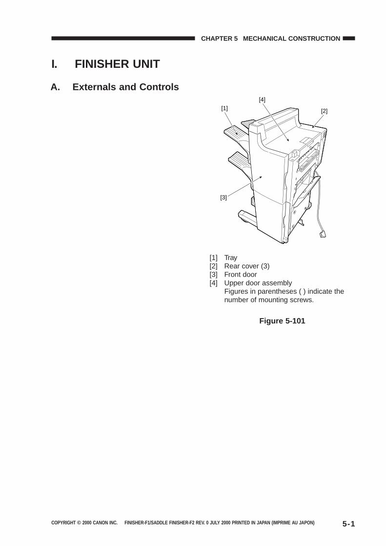
COPYRIGHT © 2000 CANON INC. FINISHER-F1/SADDLE FINISHER-F2 REV. 0 JULY 2000 PRINTED IN JAPAN (IMPRIME AU JAPON) 5-1
CHAPTER 5 MECHANICAL CONSTRUCTION
I. FINISHER UNIT
[4]
[2]
[3]
[1]
Figure 5-101
[1] Tray[2] Rear cover (3)[3] Front door[4] Upper door assembly
Figures in parentheses ( ) indicate thenumber of mounting screws.
A. Externals and Controls
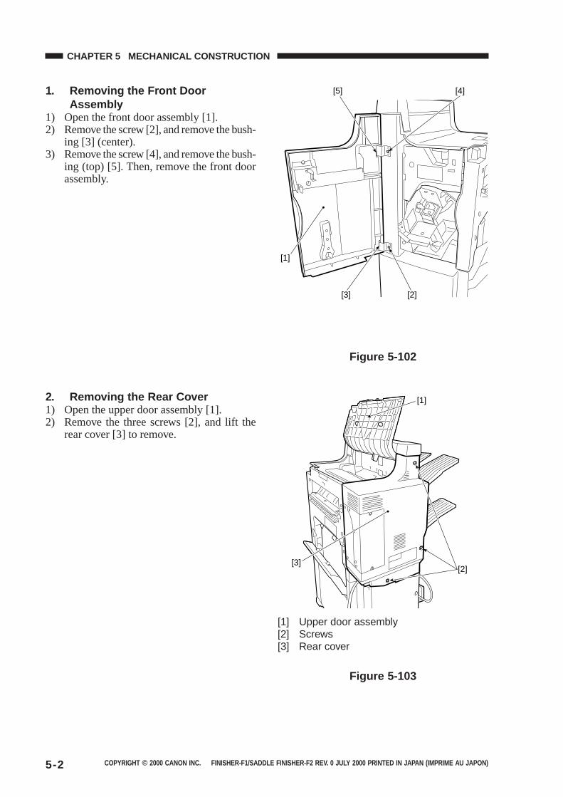
COPYRIGHT © 2000 CANON INC. FINISHER-F1/SADDLE FINISHER-F2 REV. 0 JULY 2000 PRINTED IN JAPAN (IMPRIME AU JAPON)5-2
CHAPTER 5 MECHANICAL CONSTRUCTION
1. Removing the Front DoorAssembly
1) Open the front door assembly [1].2) Remove the screw [2], and remove the bush-
ing [3] (center).3) Remove the screw [4], and remove the bush-
ing (top) [5]. Then, remove the front doorassembly.
[4][5]
[1]
[3] [2]
Figure 5-102
2. Removing the Rear Cover1) Open the upper door assembly [1].2) Remove the three screws [2], and lift the
rear cover [3] to remove.
[1] Upper door assembly[2] Screws[3] Rear cover
Figure 5-103
[3][2]
[1]

COPYRIGHT © 2000 CANON INC. FINISHER-F1/SADDLE FINISHER-F2 REV. 0 JULY 2000 PRINTED IN JAPAN (IMPRIME AU JAPON) 5-3
CHAPTER 5 MECHANICAL CONSTRUCTION
3. Removing the Upper DoorAssembly
1) Open the upper door assembly [1].2) Remove the two claws [2], and remove the
upper door assembly.
Figure 5-104
4. Removing the Front Cover1) Open the front door assembly [1].2) Remove the screw [2], and remove the front
cover [3].
Figure 5-105
[1]
[2]
[1]
[3][2]
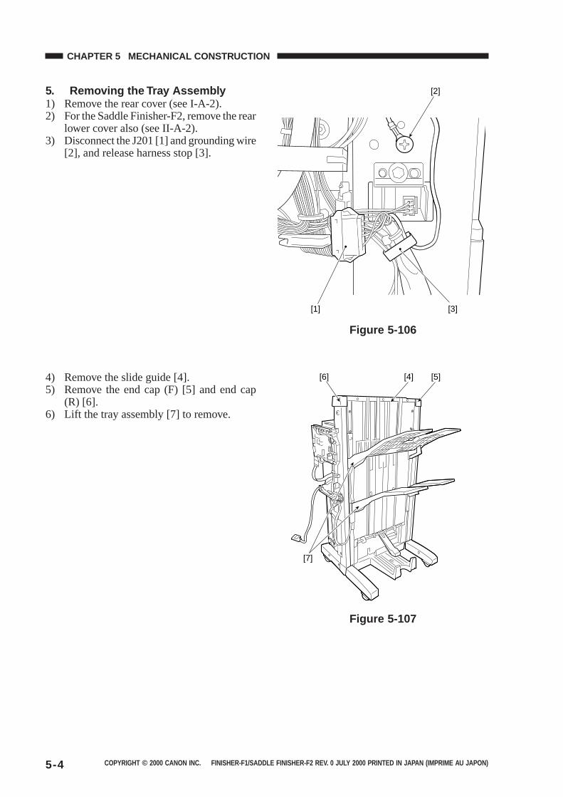
COPYRIGHT © 2000 CANON INC. FINISHER-F1/SADDLE FINISHER-F2 REV. 0 JULY 2000 PRINTED IN JAPAN (IMPRIME AU JAPON)5-4
CHAPTER 5 MECHANICAL CONSTRUCTION
4) Remove the slide guide [4].5) Remove the end cap (F) [5] and end cap
(R) [6].6) Lift the tray assembly [7] to remove.
Figure 5-107
5. Removing the Tray Assembly1) Remove the rear cover (see I-A-2).2) For the Saddle Finisher-F2, remove the rear
lower cover also (see II-A-2).3) Disconnect the J201 [1] and grounding wire
[2], and release harness stop [3].
Figure 5-106
[2]
[1] [3]
[5][6] [4]
[7]
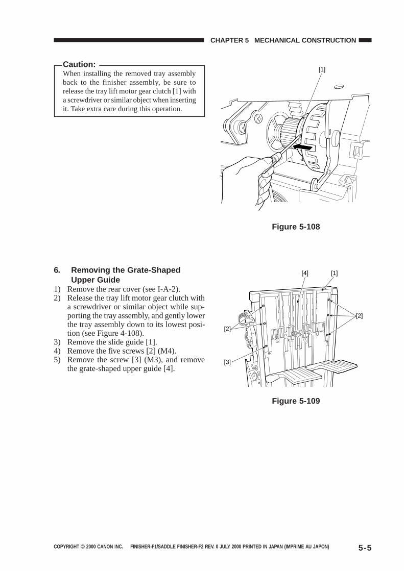
COPYRIGHT © 2000 CANON INC. FINISHER-F1/SADDLE FINISHER-F2 REV. 0 JULY 2000 PRINTED IN JAPAN (IMPRIME AU JAPON) 5-5
CHAPTER 5 MECHANICAL CONSTRUCTION
Figure 5-109
Figure 5-108
Caution:When installing the removed tray assemblyback to the finisher assembly, be sure torelease the tray lift motor gear clutch [1] witha screwdriver or similar object when insertingit. Take extra care during this operation.
6. Removing the Grate-ShapedUpper Guide
1) Remove the rear cover (see I-A-2).2) Release the tray lift motor gear clutch with
a screwdriver or similar object while sup-porting the tray assembly, and gently lowerthe tray assembly down to its lowest posi-tion (see Figure 4-108).
3) Remove the slide guide [1].4) Remove the five screws [2] (M4).5) Remove the screw [3] (M3), and remove
the grate-shaped upper guide [4].
[1]
[1][4]
[2]
[3]
[2]
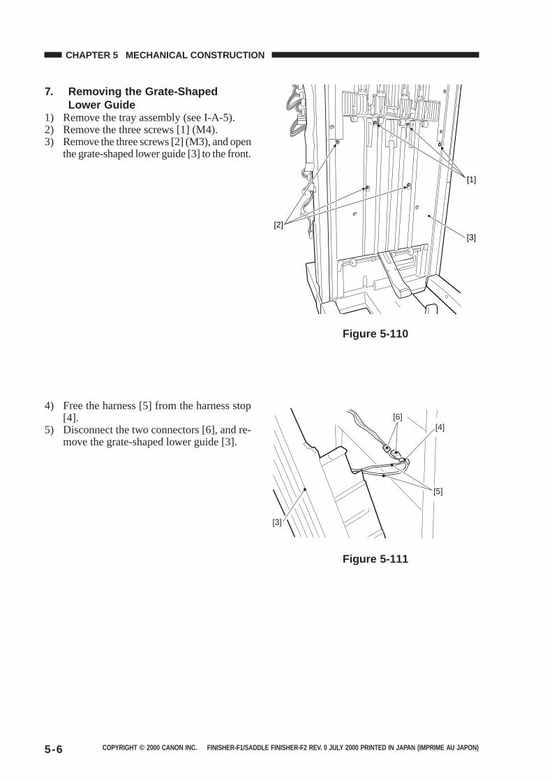
COPYRIGHT © 2000 CANON INC. FINISHER-F1/SADDLE FINISHER-F2 REV. 0 JULY 2000 PRINTED IN JAPAN (IMPRIME AU JAPON)5-6
CHAPTER 5 MECHANICAL CONSTRUCTION
7. Removing the Grate-ShapedLower Guide
1) Remove the tray assembly (see I-A-5).2) Remove the three screws [1] (M4).3) Remove the three screws [2] (M3), and open
the grate-shaped lower guide [3] to the front.
Figure 5-110
4) Free the harness [5] from the harness stop[4].
5) Disconnect the two connectors [6], and re-move the grate-shaped lower guide [3].
Figure 5-111
[1]
[2]
[3]
[4][6]
[5]
[3]
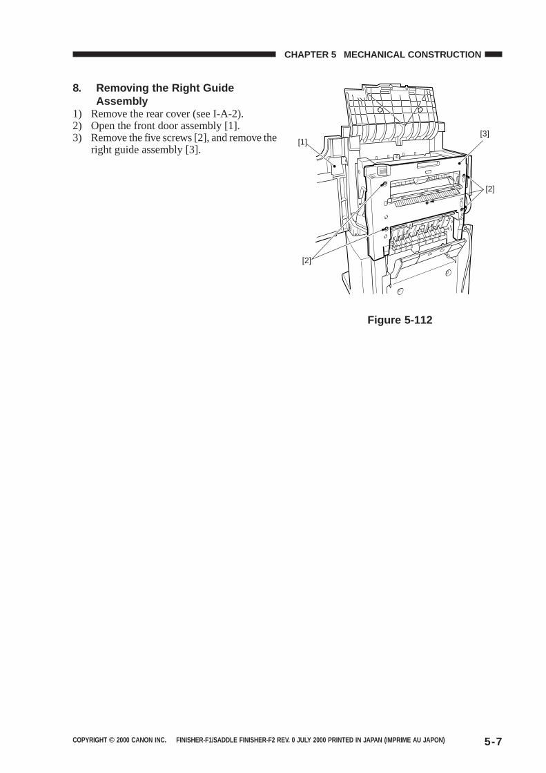
COPYRIGHT © 2000 CANON INC. FINISHER-F1/SADDLE FINISHER-F2 REV. 0 JULY 2000 PRINTED IN JAPAN (IMPRIME AU JAPON) 5-7
CHAPTER 5 MECHANICAL CONSTRUCTION
8. Removing the Right GuideAssembly
1) Remove the rear cover (see I-A-2).2) Open the front door assembly [1].3) Remove the five screws [2], and remove the
right guide assembly [3].
Figure 5-112
[3]
[2]
[2]
[1]
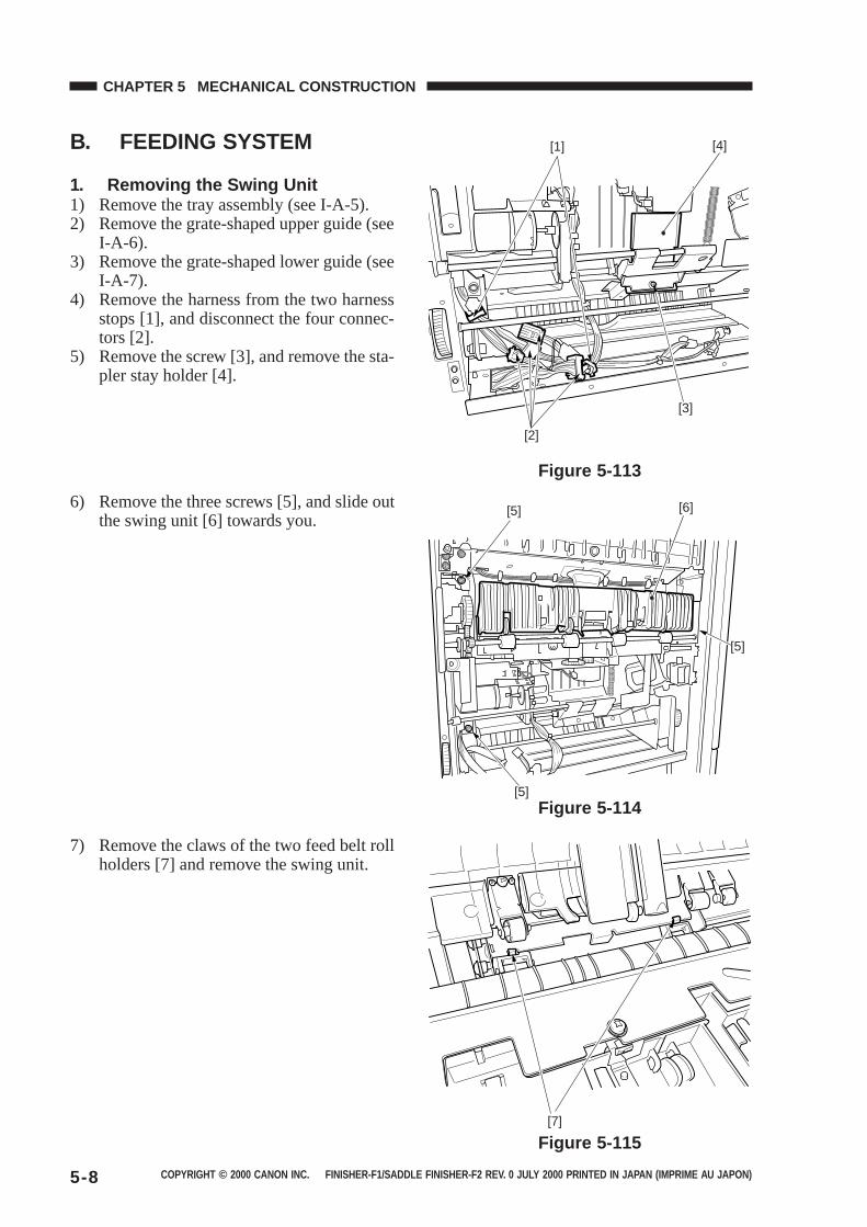
COPYRIGHT © 2000 CANON INC. FINISHER-F1/SADDLE FINISHER-F2 REV. 0 JULY 2000 PRINTED IN JAPAN (IMPRIME AU JAPON)5-8
CHAPTER 5 MECHANICAL CONSTRUCTION
B. FEEDING SYSTEM
1. Removing the Swing Unit1) Remove the tray assembly (see I-A-5).2) Remove the grate-shaped upper guide (see
I-A-6).3) Remove the grate-shaped lower guide (see
I-A-7).4) Remove the harness from the two harness
stops [1], and disconnect the four connec-tors [2].
5) Remove the screw [3], and remove the sta-pler stay holder [4].
Figure 5-113
6) Remove the three screws [5], and slide outthe swing unit [6] towards you.
Figure 5-114
7) Remove the claws of the two feed belt rollholders [7] and remove the swing unit.
Figure 5-115
[3]
[4]
[2]
[1]
[6][5]
[5]
[5]
[7]

COPYRIGHT © 2000 CANON INC. FINISHER-F1/SADDLE FINISHER-F2 REV. 0 JULY 2000 PRINTED IN JAPAN (IMPRIME AU JAPON) 5-9
CHAPTER 5 MECHANICAL CONSTRUCTION
2. Removing the Feed Drive Unit1) Remove the finisher controller PCB (see I-
C-1).2) Remove the harness leads [2] from the two
harness stops [1] at the PCB base, and dis-connect the two connectors [3].
Figure 5-116
3) Remove the ground lead [4] and the threescrews [5], and pull down PCB base [6] to-wards you.
Figure 5-117
4) Remove the harness leads [8] from the twoedge saddles [7], and remove the PCB base.
Figure 5-118
[3]
[1] [2] [1]
[4]
[5]
[6]
[5]
[8]
[7][7]
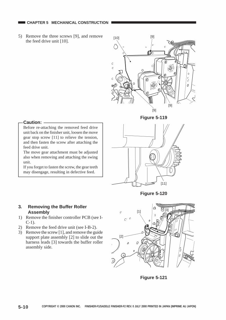
COPYRIGHT © 2000 CANON INC. FINISHER-F1/SADDLE FINISHER-F2 REV. 0 JULY 2000 PRINTED IN JAPAN (IMPRIME AU JAPON)5-10
CHAPTER 5 MECHANICAL CONSTRUCTION
5) Remove the three screws [9], and removethe feed drive unit [10].
Figure 5-119
Figure 5-120
3. Removing the Buffer RollerAssembly
1) Remove the finisher controller PCB (see I-C-1).
2) Remove the feed drive unit (see I-B-2).3) Remove the screw [1], and remove the guide
support plate assembly [2] to slide out theharness leads [3] towards the buffer rollerassembly side.
Figure 5-121
Caution:Before re-attaching the removed feed driveunit back on the finisher unit, loosen the movegear stop screw [11] to relieve the tension,and then fasten the screw after attaching thefeed drive unit.The move gear attachment must be adjustedalso when removing and attaching the swingunit.If you forget to fasten the screw, the gear teethmay disengage, resulting in defective feed.
[9]
[9][9]
[10]
[11]
[1]
[2]
[3]
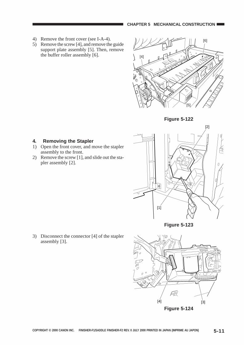
COPYRIGHT © 2000 CANON INC. FINISHER-F1/SADDLE FINISHER-F2 REV. 0 JULY 2000 PRINTED IN JAPAN (IMPRIME AU JAPON) 5-11
CHAPTER 5 MECHANICAL CONSTRUCTION
4) Remove the front cover (see I-A-4).5) Remove the screw [4], and remove the guide
support plate assembly [5]. Then, removethe buffer roller assembly [6].
Figure 5-122
Figure 5-123
Figure 5-124
4. Removing the Stapler1) Open the front cover, and move the stapler
assembly to the front.2) Remove the screw [1], and slide out the sta-
pler assembly [2].
3) Disconnect the connector [4] of the staplerassembly [3].
[6]
[5]
[4]
[2]
[1]
[4] [3]
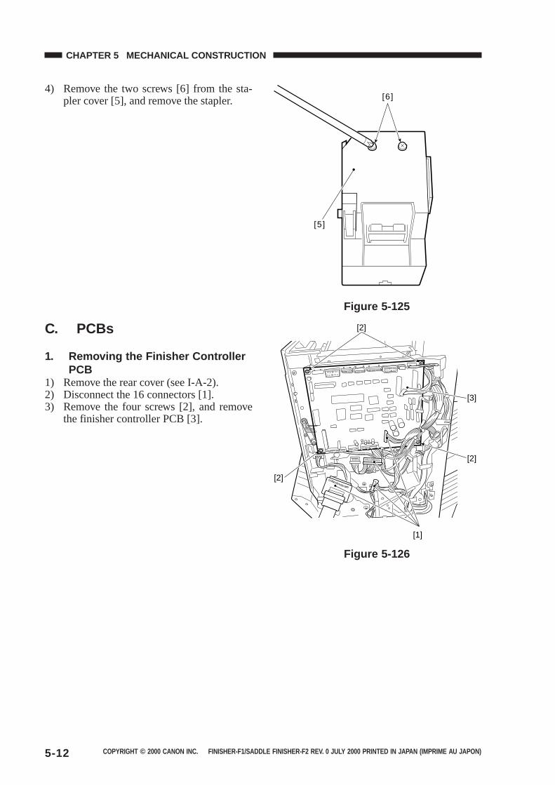
COPYRIGHT © 2000 CANON INC. FINISHER-F1/SADDLE FINISHER-F2 REV. 0 JULY 2000 PRINTED IN JAPAN (IMPRIME AU JAPON)5-12
CHAPTER 5 MECHANICAL CONSTRUCTION
4) Remove the two screws [6] from the sta-pler cover [5], and remove the stapler.
Figure 5-125
C. PCBs
1. Removing the Finisher ControllerPCB
1) Remove the rear cover (see I-A-2).2) Disconnect the 16 connectors [1].3) Remove the four screws [2], and remove
the finisher controller PCB [3].
Figure 5-126
[5]
[6]
[2]
[1]
[3]
[2]
[2]
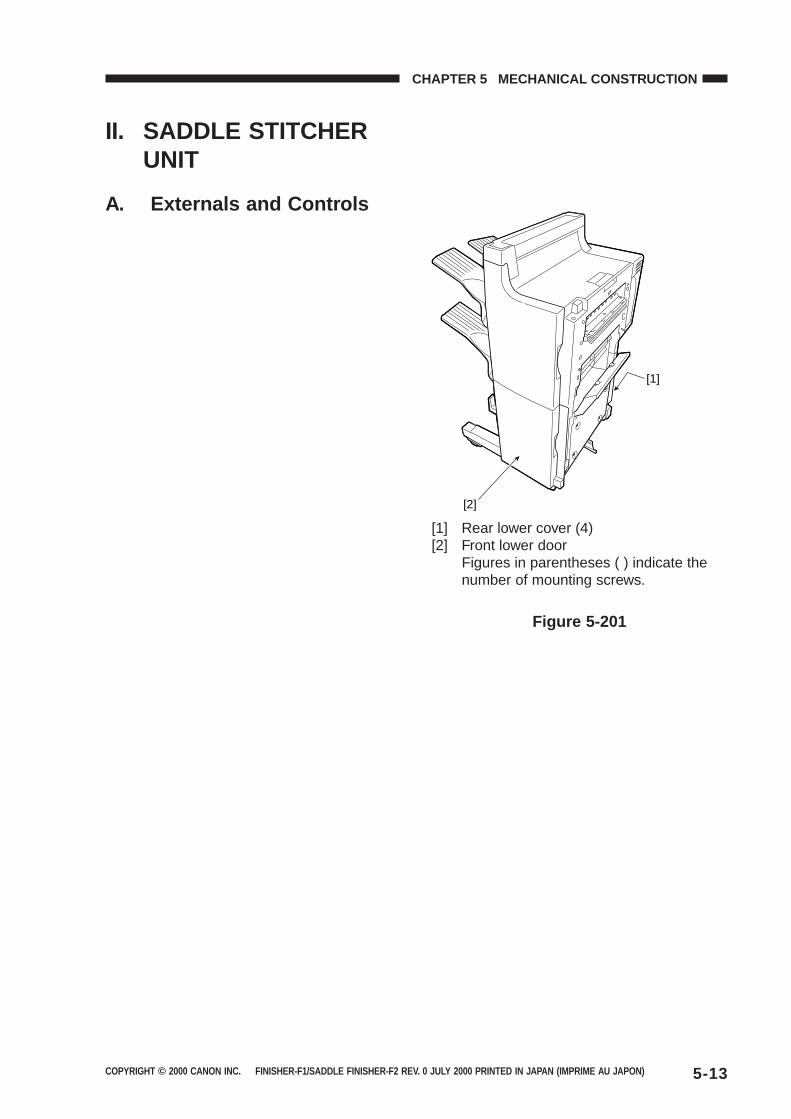
COPYRIGHT © 2000 CANON INC. FINISHER-F1/SADDLE FINISHER-F2 REV. 0 JULY 2000 PRINTED IN JAPAN (IMPRIME AU JAPON) 5-13
CHAPTER 5 MECHANICAL CONSTRUCTION
II. SADDLE STITCHERUNIT
A. Externals and Controls
[1] Rear lower cover (4)[2] Front lower door
Figures in parentheses ( ) indicate thenumber of mounting screws.
Figure 5-201
[2]
[1]
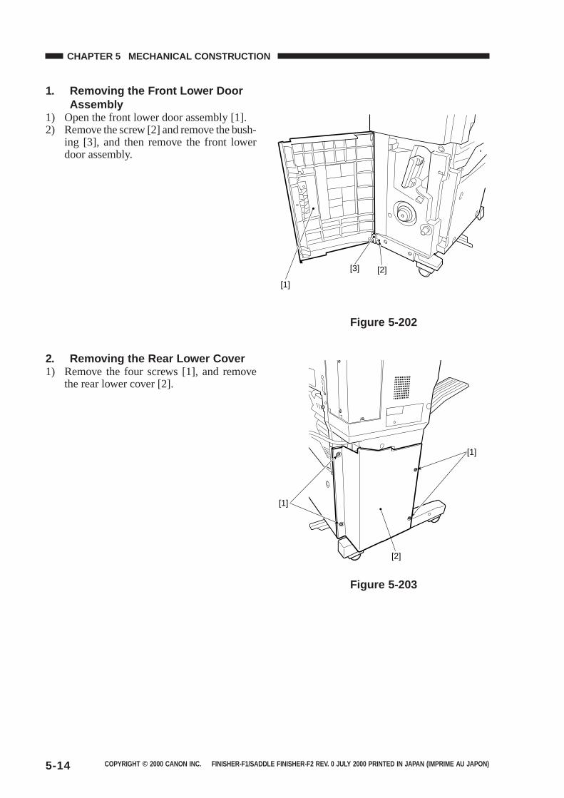
COPYRIGHT © 2000 CANON INC. FINISHER-F1/SADDLE FINISHER-F2 REV. 0 JULY 2000 PRINTED IN JAPAN (IMPRIME AU JAPON)5-14
CHAPTER 5 MECHANICAL CONSTRUCTION
1. Removing the Front Lower DoorAssembly
1) Open the front lower door assembly [1].2) Remove the screw [2] and remove the bush-
ing [3], and then remove the front lowerdoor assembly.
Figure 5-202
2. Removing the Rear Lower Cover1) Remove the four screws [1], and remove
the rear lower cover [2].
Figure 5-203
[1]
[3] [2]
[1]
[2]
[1]
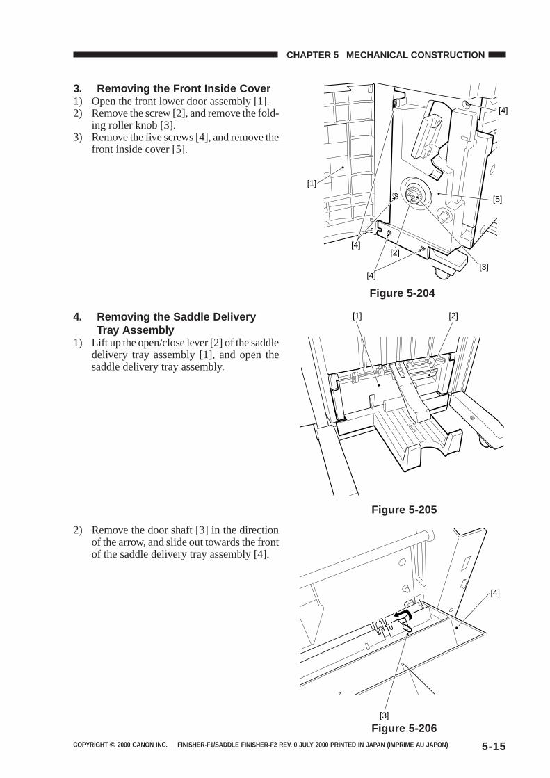
COPYRIGHT © 2000 CANON INC. FINISHER-F1/SADDLE FINISHER-F2 REV. 0 JULY 2000 PRINTED IN JAPAN (IMPRIME AU JAPON) 5-15
CHAPTER 5 MECHANICAL CONSTRUCTION
3. Removing the Front Inside Cover1) Open the front lower door assembly [1].2) Remove the screw [2], and remove the fold-
ing roller knob [3].3) Remove the five screws [4], and remove the
front inside cover [5].
Figure 5-204
4. Removing the Saddle DeliveryTray Assembly
1) Lift up the open/close lever [2] of the saddledelivery tray assembly [1], and open thesaddle delivery tray assembly.
Figure 5-205
2) Remove the door shaft [3] in the directionof the arrow, and slide out towards the frontof the saddle delivery tray assembly [4].
Figure 5-206
[1]
[4]
[4][3]
[5]
[4]
[2]
[1] [2]
[3]
[4]
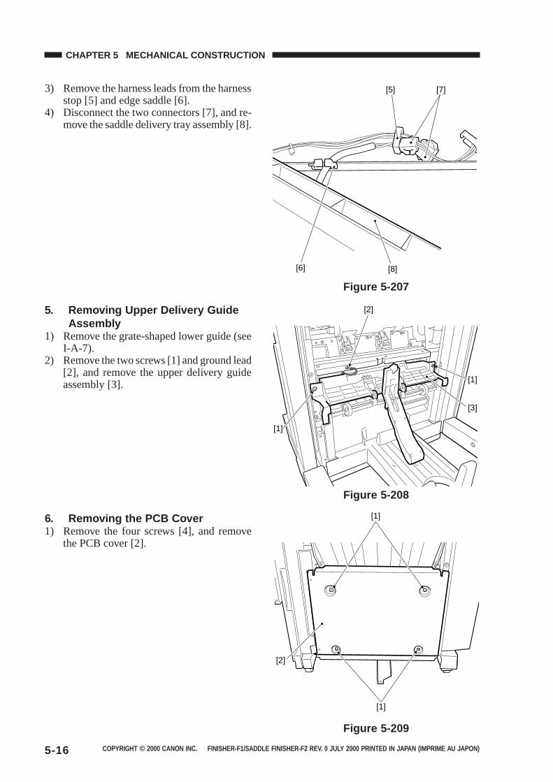
COPYRIGHT © 2000 CANON INC. FINISHER-F1/SADDLE FINISHER-F2 REV. 0 JULY 2000 PRINTED IN JAPAN (IMPRIME AU JAPON)5-16
CHAPTER 5 MECHANICAL CONSTRUCTION
3) Remove the harness leads from the harnessstop [5] and edge saddle [6].
4) Disconnect the two connectors [7], and re-move the saddle delivery tray assembly [8].
Figure 5-207
Figure 5-208
5. Removing Upper Delivery GuideAssembly
1) Remove the grate-shaped lower guide (seeI-A-7).
2) Remove the two screws [1] and ground lead[2], and remove the upper delivery guideassembly [3].
6. Removing the PCB Cover1) Remove the four screws [4], and remove
the PCB cover [2].
Figure 5-209
[7][5]
[6] [8]
[1]
[3]
[2]
[1]
[1]
[2]
[1]
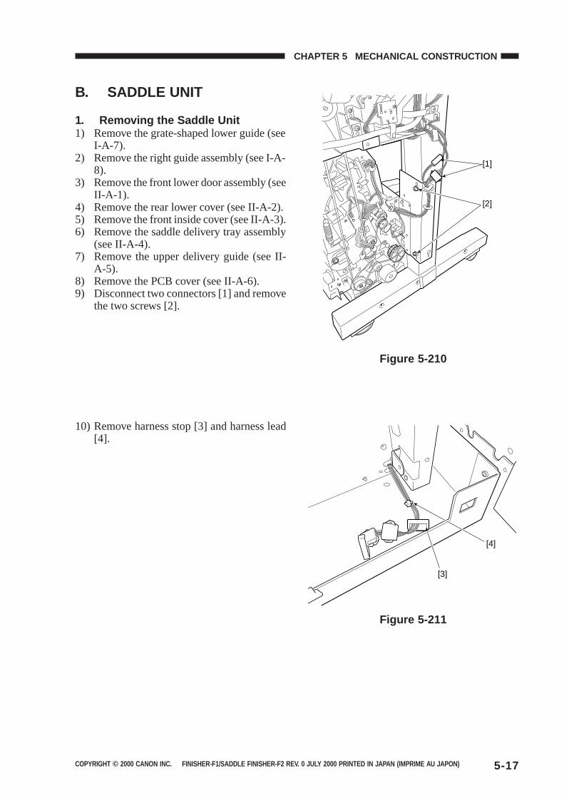
COPYRIGHT © 2000 CANON INC. FINISHER-F1/SADDLE FINISHER-F2 REV. 0 JULY 2000 PRINTED IN JAPAN (IMPRIME AU JAPON) 5-17
CHAPTER 5 MECHANICAL CONSTRUCTION
B. SADDLE UNIT
1. Removing the Saddle Unit1) Remove the grate-shaped lower guide (see
I-A-7).2) Remove the right guide assembly (see I-A-
8).3) Remove the front lower door assembly (see
II-A-1).4) Remove the rear lower cover (see II-A-2).5) Remove the front inside cover (see II-A-3).6) Remove the saddle delivery tray assembly
(see II-A-4).7) Remove the upper delivery guide (see II-
A-5).8) Remove the PCB cover (see II-A-6).9) Disconnect two connectors [1] and remove
the two screws [2].
Figure 5-210
Figure 5-211
10) Remove harness stop [3] and harness lead[4].
[1]
[2]
[3]
[4]
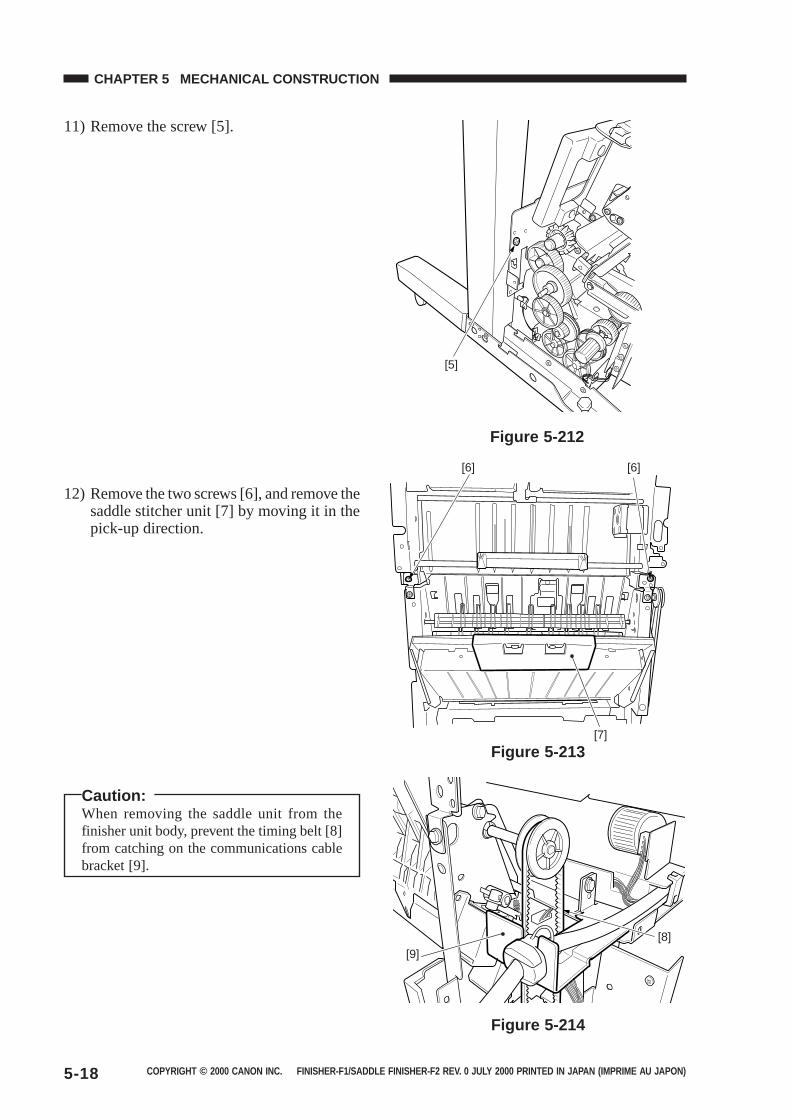
COPYRIGHT © 2000 CANON INC. FINISHER-F1/SADDLE FINISHER-F2 REV. 0 JULY 2000 PRINTED IN JAPAN (IMPRIME AU JAPON)5-18
CHAPTER 5 MECHANICAL CONSTRUCTION
11) Remove the screw [5].
12) Remove the two screws [6], and remove thesaddle stitcher unit [7] by moving it in thepick-up direction.
Figure 5-212
Figure 5-213
Figure 5-214
Caution:When removing the saddle unit from thefinisher unit body, prevent the timing belt [8]from catching on the communications cablebracket [9].
[5]
[6][6]
[7]
[9][8]
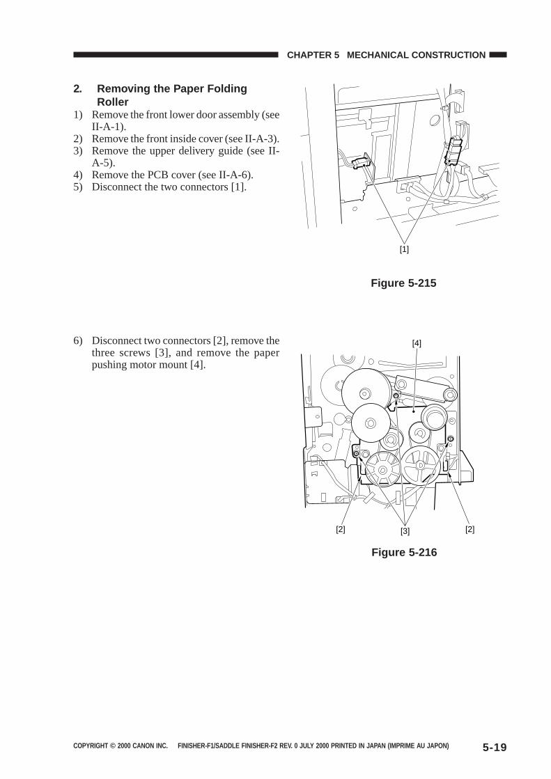
COPYRIGHT © 2000 CANON INC. FINISHER-F1/SADDLE FINISHER-F2 REV. 0 JULY 2000 PRINTED IN JAPAN (IMPRIME AU JAPON) 5-19
CHAPTER 5 MECHANICAL CONSTRUCTION
2. Removing the Paper FoldingRoller
1) Remove the front lower door assembly (seeII-A-1).
2) Remove the front inside cover (see II-A-3).3) Remove the upper delivery guide (see II-
A-5).4) Remove the PCB cover (see II-A-6).5) Disconnect the two connectors [1].
6) Disconnect two connectors [2], remove thethree screws [3], and remove the paperpushing motor mount [4].
Figure 5-215
Figure 5-216
[1]
[2] [2][3]
[4]
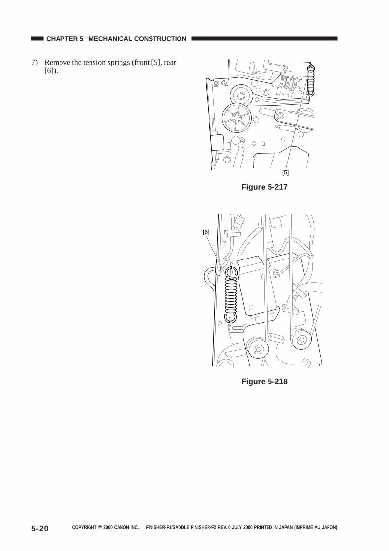
COPYRIGHT © 2000 CANON INC. FINISHER-F1/SADDLE FINISHER-F2 REV. 0 JULY 2000 PRINTED IN JAPAN (IMPRIME AU JAPON)5-20
CHAPTER 5 MECHANICAL CONSTRUCTION
7) Remove the tension springs (front [5], rear[6]).
Figure 5-217
Figure 5-218
[5]
[6]
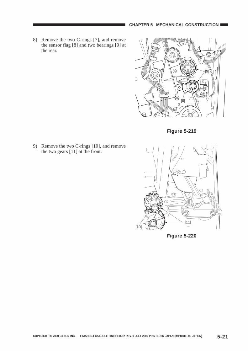
COPYRIGHT © 2000 CANON INC. FINISHER-F1/SADDLE FINISHER-F2 REV. 0 JULY 2000 PRINTED IN JAPAN (IMPRIME AU JAPON) 5-21
CHAPTER 5 MECHANICAL CONSTRUCTION
8) Remove the two C-rings [7], and removethe sensor flag [8] and two bearings [9] atthe rear.
Figure 5-219
9) Remove the two C-rings [10], and removethe two gears [11] at the front.
Figure 5-220
[9]
[7]
[8]
[11][10]
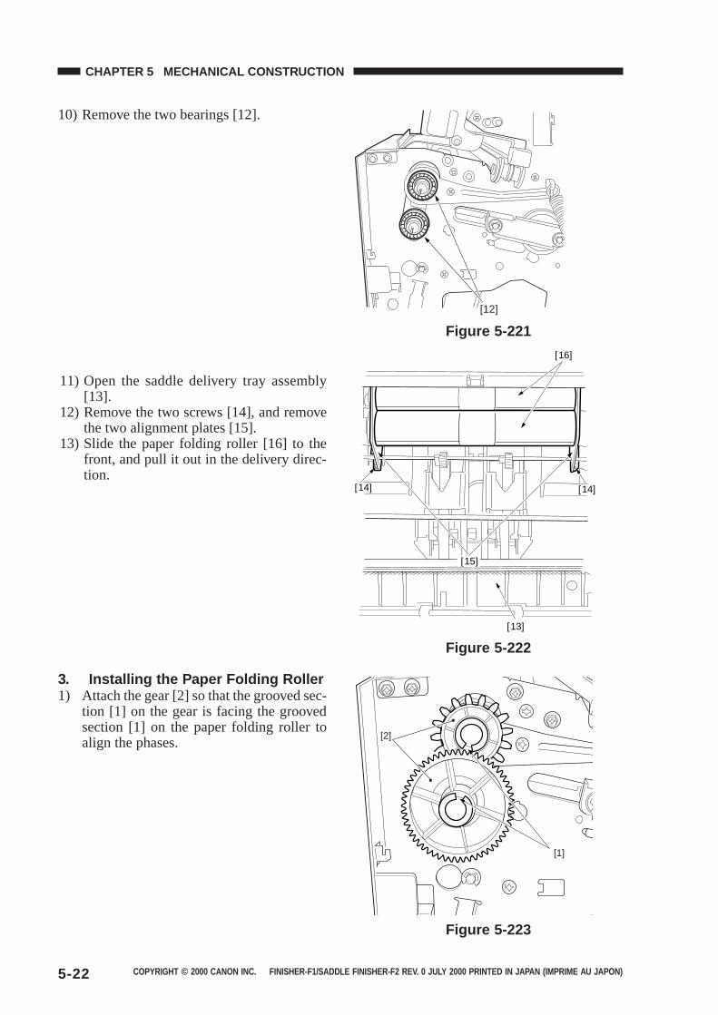
COPYRIGHT © 2000 CANON INC. FINISHER-F1/SADDLE FINISHER-F2 REV. 0 JULY 2000 PRINTED IN JAPAN (IMPRIME AU JAPON)5-22
CHAPTER 5 MECHANICAL CONSTRUCTION
10) Remove the two bearings [12].
11) Open the saddle delivery tray assembly[13].
12) Remove the two screws [14], and removethe two alignment plates [15].
13) Slide the paper folding roller [16] to thefront, and pull it out in the delivery direc-tion.
Figure 5-221
Figure 5-222
3. Installing the Paper Folding Roller1) Attach the gear [2] so that the grooved sec-
tion [1] on the gear is facing the groovedsection [1] on the paper folding roller toalign the phases.
Figure 5-223
[12]
[13]
[15]
[14] [14]
[16]
[2]
[1]
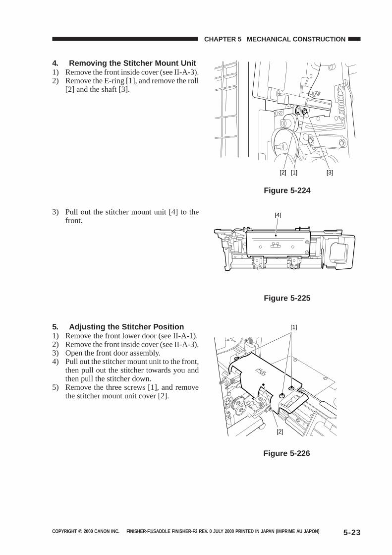
COPYRIGHT © 2000 CANON INC. FINISHER-F1/SADDLE FINISHER-F2 REV. 0 JULY 2000 PRINTED IN JAPAN (IMPRIME AU JAPON) 5-23
CHAPTER 5 MECHANICAL CONSTRUCTION
4. Removing the Stitcher Mount Unit1) Remove the front inside cover (see II-A-3).2) Remove the E-ring [1], and remove the roll
[2] and the shaft [3].
Figure 5-224
Figure 5-226
3) Pull out the stitcher mount unit [4] to thefront.
Figure 5-225
5. Adjusting the Stitcher Position1) Remove the front lower door (see II-A-1).2) Remove the front inside cover (see II-A-3).3) Open the front door assembly.4) Pull out the stitcher mount unit to the front,
then pull out the stitcher towards you andthen pull the stitcher down.
5) Remove the three screws [1], and removethe stitcher mount unit cover [2].
[1][2] [3]
[4]
[1]
[2]
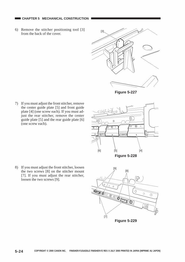
COPYRIGHT © 2000 CANON INC. FINISHER-F1/SADDLE FINISHER-F2 REV. 0 JULY 2000 PRINTED IN JAPAN (IMPRIME AU JAPON)5-24
CHAPTER 5 MECHANICAL CONSTRUCTION
6) Remove the stitcher positioning tool [3]from the back of the cover.
Figure 5-227
7) If you must adjust the front stitcher, removethe center guide plate [5] and front guideplate [4] (one screw each). If you must ad-just the rear stitcher, remove the centerguide plate [5] and the rear guide plate [6](one screw each).
Figure 5-228
8) If you must adjust the front stitcher, loosenthe two screws [8] on the stitcher mount[7]. If you must adjust the rear stitcher,loosen the two screws [9].
Figure 5-229
[3]
[6] [5] [4]
[9][8]
[7]

COPYRIGHT © 2000 CANON INC. FINISHER-F1/SADDLE FINISHER-F2 REV. 0 JULY 2000 PRINTED IN JAPAN (IMPRIME AU JAPON) 5-25
CHAPTER 5 MECHANICAL CONSTRUCTION
9) Insert the tool [10] into the staple slot ofthe stitcher [9].
Figure 5-230
10) Shift down the stitcher, and turn the stitchergear so that the boss on the tool [11] andthe recess of the mount match. Then, tightenthe screws [12] on the mount to fix the twoin place.
Figure 5-231
6. Removing the Positioning PlateUnit
1) Remove the saddle stitcher controller PCB(see II-C-1).
2) Disconnect the two connectors [1], removethe three harness stops [2], and remove theharness leads [3] from the two edge saddles[4].
3) Remove the two screws [5], slide the posi-tioning plate unit [6] once towards the frontand remove from the rear side.
Figure 5-232
[9][10]
[11]
[12]
[1]
[2][3]
[6]
[5] [4]
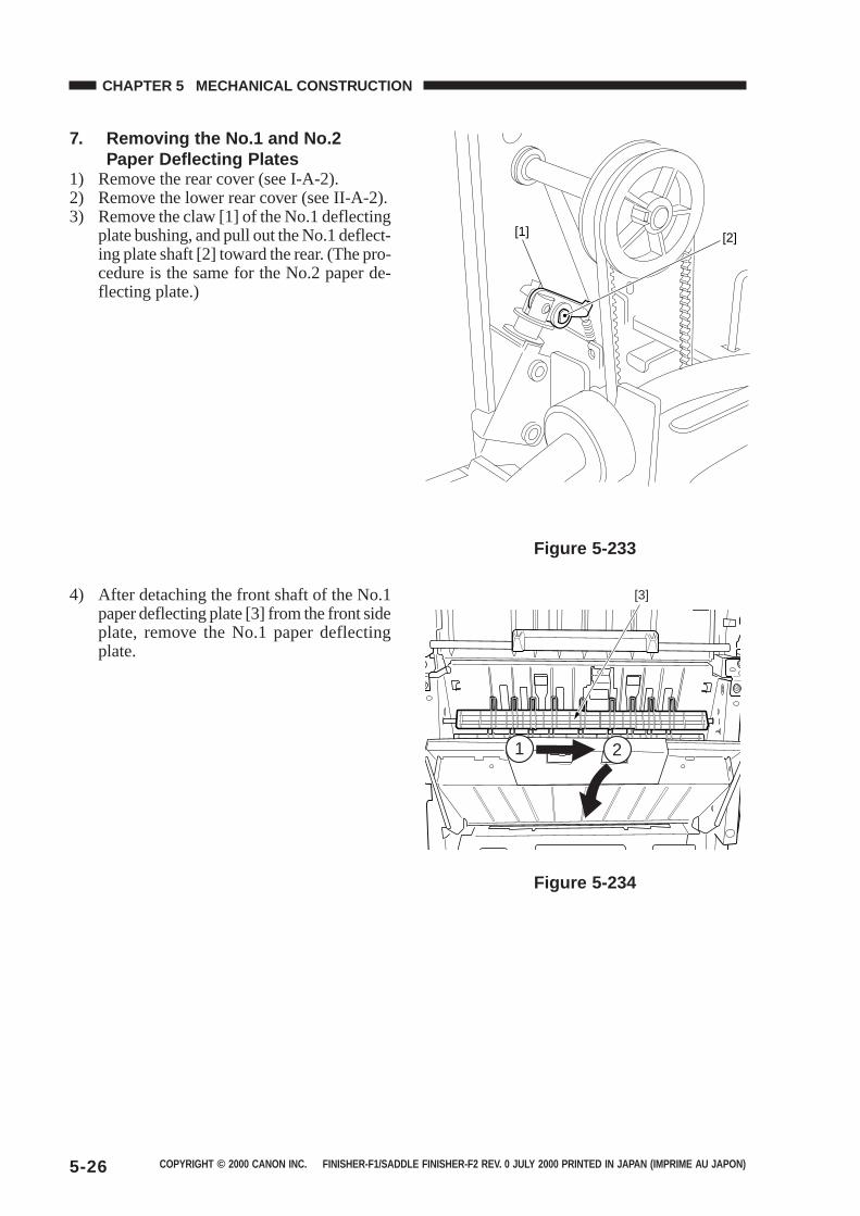
COPYRIGHT © 2000 CANON INC. FINISHER-F1/SADDLE FINISHER-F2 REV. 0 JULY 2000 PRINTED IN JAPAN (IMPRIME AU JAPON)5-26
CHAPTER 5 MECHANICAL CONSTRUCTION
7. Removing the No.1 and No.2Paper Deflecting Plates
1) Remove the rear cover (see I-A-2).2) Remove the lower rear cover (see II-A-2).3) Remove the claw [1] of the No.1 deflecting
plate bushing, and pull out the No.1 deflect-ing plate shaft [2] toward the rear. (The pro-cedure is the same for the No.2 paper de-flecting plate.)
Figure 5-234
Figure 5-233
4) After detaching the front shaft of the No.1paper deflecting plate [3] from the front sideplate, remove the No.1 paper deflectingplate.
[1] [2]
[3]
1 2
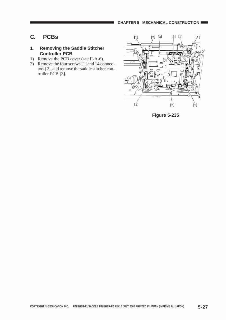
COPYRIGHT © 2000 CANON INC. FINISHER-F1/SADDLE FINISHER-F2 REV. 0 JULY 2000 PRINTED IN JAPAN (IMPRIME AU JAPON) 5-27
CHAPTER 5 MECHANICAL CONSTRUCTION
C. PCBs
1. Removing the Saddle StitcherController PCB
1) Remove the PCB cover (see II-A-6).2) Remove the four screws [1] and 14 connec-
tors [2], and remove the saddle stitcher con-troller PCB [3].
Figure 5-235
[1] [1]
[1][1]
[2] [3] [2] [2]
[2]
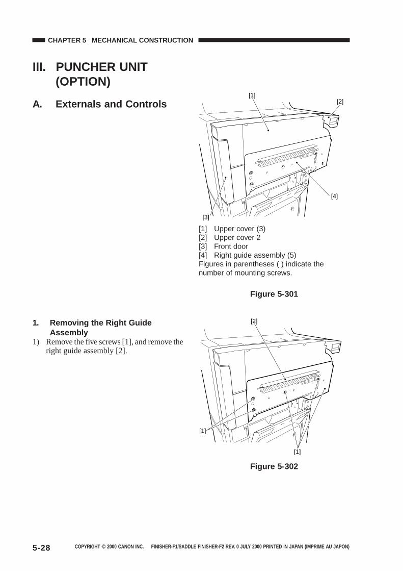
COPYRIGHT © 2000 CANON INC. FINISHER-F1/SADDLE FINISHER-F2 REV. 0 JULY 2000 PRINTED IN JAPAN (IMPRIME AU JAPON)5-28
CHAPTER 5 MECHANICAL CONSTRUCTION
III. PUNCHER UNIT(OPTION)
A. Externals and Controls
[1] Upper cover (3)[2] Upper cover 2[3] Front door[4] Right guide assembly (5)Figures in parentheses ( ) indicate thenumber of mounting screws.
Figure 5-301
Figure 5-302
1. Removing the Right GuideAssembly
1) Remove the five screws [1], and remove theright guide assembly [2].
[1][2]
[4]
[3]
[2]
[1]
[1]
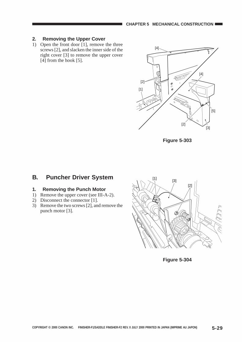
COPYRIGHT © 2000 CANON INC. FINISHER-F1/SADDLE FINISHER-F2 REV. 0 JULY 2000 PRINTED IN JAPAN (IMPRIME AU JAPON) 5-29
CHAPTER 5 MECHANICAL CONSTRUCTION
2. Removing the Upper Cover1) Open the front door [1], remove the three
screws [2], and slacken the inner side of theright cover [3] to remove the upper cover[4] from the hook [5].
Figure 5-303
Figure 5-304
B. Puncher Driver System
1. Removing the Punch Motor1) Remove the upper cover (see III-A-2).2) Disconnect the connector [1].3) Remove the two screws [2], and remove the
punch motor [3].
[2]
[2]
[4]
[4]
[3]
[5]
[1]
[3][1]
[2]
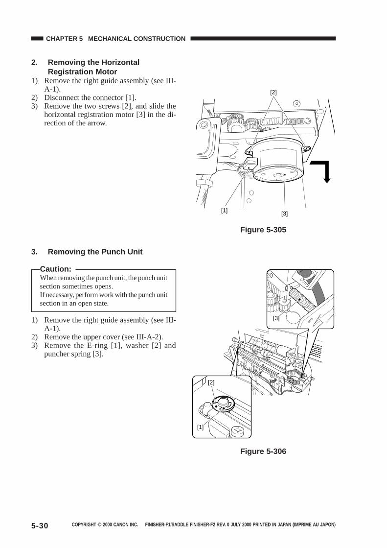
COPYRIGHT © 2000 CANON INC. FINISHER-F1/SADDLE FINISHER-F2 REV. 0 JULY 2000 PRINTED IN JAPAN (IMPRIME AU JAPON)5-30
CHAPTER 5 MECHANICAL CONSTRUCTION
2. Removing the HorizontalRegistration Motor
1) Remove the right guide assembly (see III-A-1).
2) Disconnect the connector [1].3) Remove the two screws [2], and slide the
horizontal registration motor [3] in the di-rection of the arrow.
Figure 5-305
3. Removing the Punch Unit
Caution:When removing the punch unit, the punch unitsection sometimes opens.If necessary, perform work with the punch unitsection in an open state.
1) Remove the right guide assembly (see III-A-1).
2) Remove the upper cover (see III-A-2).3) Remove the E-ring [1], washer [2] and
puncher spring [3].
Figure 5-306
[2]
[1] [3]
[3]
[1]
[2]
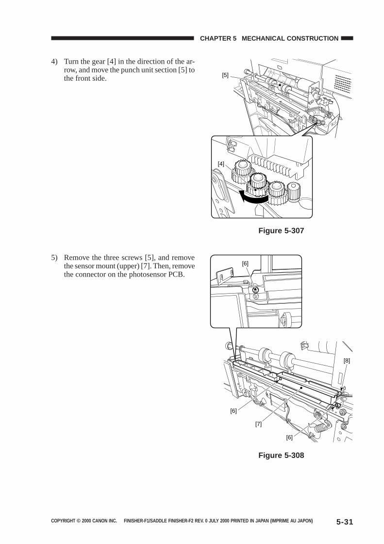
COPYRIGHT © 2000 CANON INC. FINISHER-F1/SADDLE FINISHER-F2 REV. 0 JULY 2000 PRINTED IN JAPAN (IMPRIME AU JAPON) 5-31
CHAPTER 5 MECHANICAL CONSTRUCTION
Figure 5-307
Figure 5-308
[5]
[4]
[7]
[6]
[8]
[6]
[6]
4) Turn the gear [4] in the direction of the ar-row, and move the punch unit section [5] tothe front side.
5) Remove the three screws [5], and removethe sensor mount (upper) [7]. Then, removethe connector on the photosensor PCB.
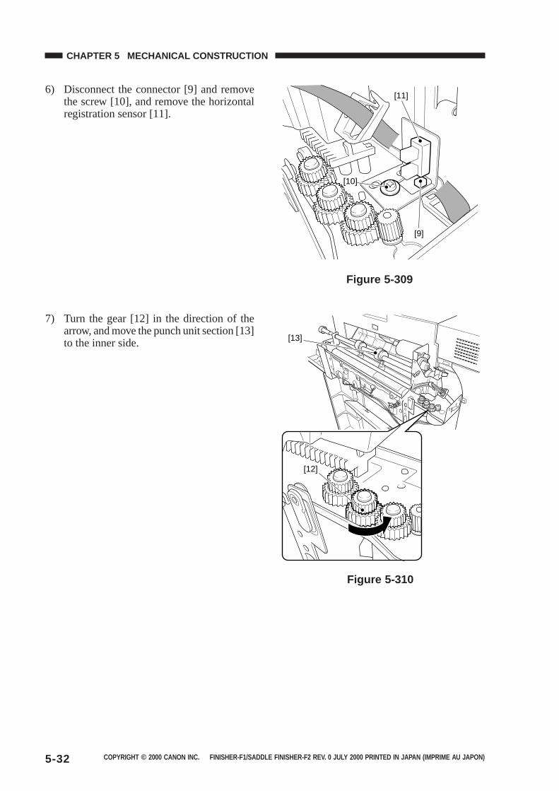
COPYRIGHT © 2000 CANON INC. FINISHER-F1/SADDLE FINISHER-F2 REV. 0 JULY 2000 PRINTED IN JAPAN (IMPRIME AU JAPON)5-32
CHAPTER 5 MECHANICAL CONSTRUCTION
Figure 5-309
Figure 5-310
[10]
[9]
[11]
[13]
[12]
7) Turn the gear [12] in the direction of thearrow, and move the punch unit section [13]to the inner side.
6) Disconnect the connector [9] and removethe screw [10], and remove the horizontalregistration sensor [11].
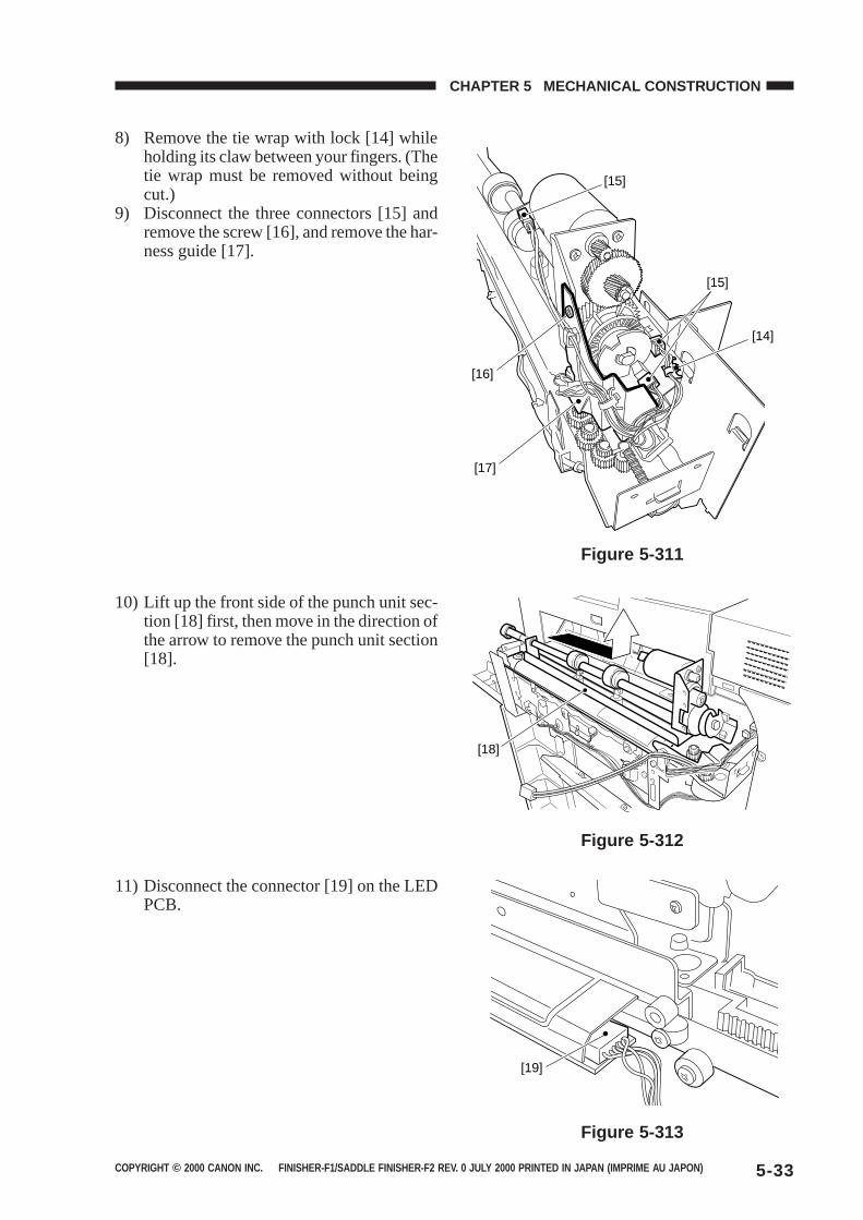
COPYRIGHT © 2000 CANON INC. FINISHER-F1/SADDLE FINISHER-F2 REV. 0 JULY 2000 PRINTED IN JAPAN (IMPRIME AU JAPON) 5-33
CHAPTER 5 MECHANICAL CONSTRUCTION
11) Disconnect the connector [19] on the LEDPCB.
Figure 5-311
Figure 5-312
Figure 5-313
[15]
[14]
[15]
[17]
[16]
10) Lift up the front side of the punch unit sec-tion [18] first, then move in the direction ofthe arrow to remove the punch unit section[18].
8) Remove the tie wrap with lock [14] whileholding its claw between your fingers. (Thetie wrap must be removed without beingcut.)
9) Disconnect the three connectors [15] andremove the screw [16], and remove the har-ness guide [17].
[18]
[19]
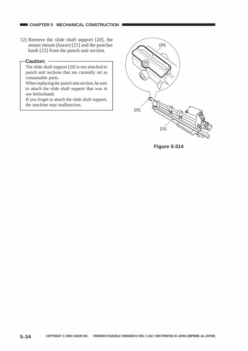
COPYRIGHT © 2000 CANON INC. FINISHER-F1/SADDLE FINISHER-F2 REV. 0 JULY 2000 PRINTED IN JAPAN (IMPRIME AU JAPON)5-34
CHAPTER 5 MECHANICAL CONSTRUCTION
12) Remove the slide shaft support [20], thesensor mount (lower) [21] and the puncherknob [22] from the punch unit section.
Caution:The slide shaft support [20] is not attached topunch unit sections that are currently set asconsumable parts.When replacing the punch unit section, be sureto attach the slide shaft support that was inuse beforehand.If you forget to attach the slide shaft support,the machine may malfunction.
Figure 5-314
[20]
[22]
[21]

COPYRIGHT © 2000 CANON INC. FINISHER-F1/SADDLE FINISHER-F2 REV. 0 JULY 2000 PRINTED IN JAPAN (IMPRIME AU JAPON) 5-35
CHAPTER 5 MECHANICAL CONSTRUCTION
4. Removing the Punch Unit Harness
Caution:When removing the punch unit, the punch unitsection sometimes opens.If necessary, perform work with the punch unitsection in an open state.
1) Remove the punch unit from the finisherassembly.
2) Remove the right guide assembly (see III-A-1).
3) Remove the upper cover (see III-A-2).4) Disconnect the four connectors [2] on the
punch driver PCB [1].
Figure 5-315
Figure 5-316
[1]
[2]
[2]
5) Remove the two tie wraps with lock [14]while holding its claw between your fin-gers. (The tie wraps must be removed with-out being cut.)
6) Disconnect the three connectors [4].7) Free the harness [6] from the three harness
stops [5].
[4]
[3]
[4]
[5]
[5]
[3]
[5]
[6]
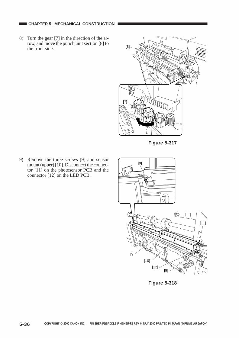
COPYRIGHT © 2000 CANON INC. FINISHER-F1/SADDLE FINISHER-F2 REV. 0 JULY 2000 PRINTED IN JAPAN (IMPRIME AU JAPON)5-36
CHAPTER 5 MECHANICAL CONSTRUCTION
Figure 5-317
Figure 5-318
8) Turn the gear [7] in the direction of the ar-row, and move the punch unit section [8] tothe front side.
9) Remove the three screws [9] and sensormount (upper) [10]. Disconnect the connec-tor [11] on the photosensor PCB and theconnector [12] on the LED PCB.
[8]
[7]
[10]
[12][9]
[9]
[11]
[9]
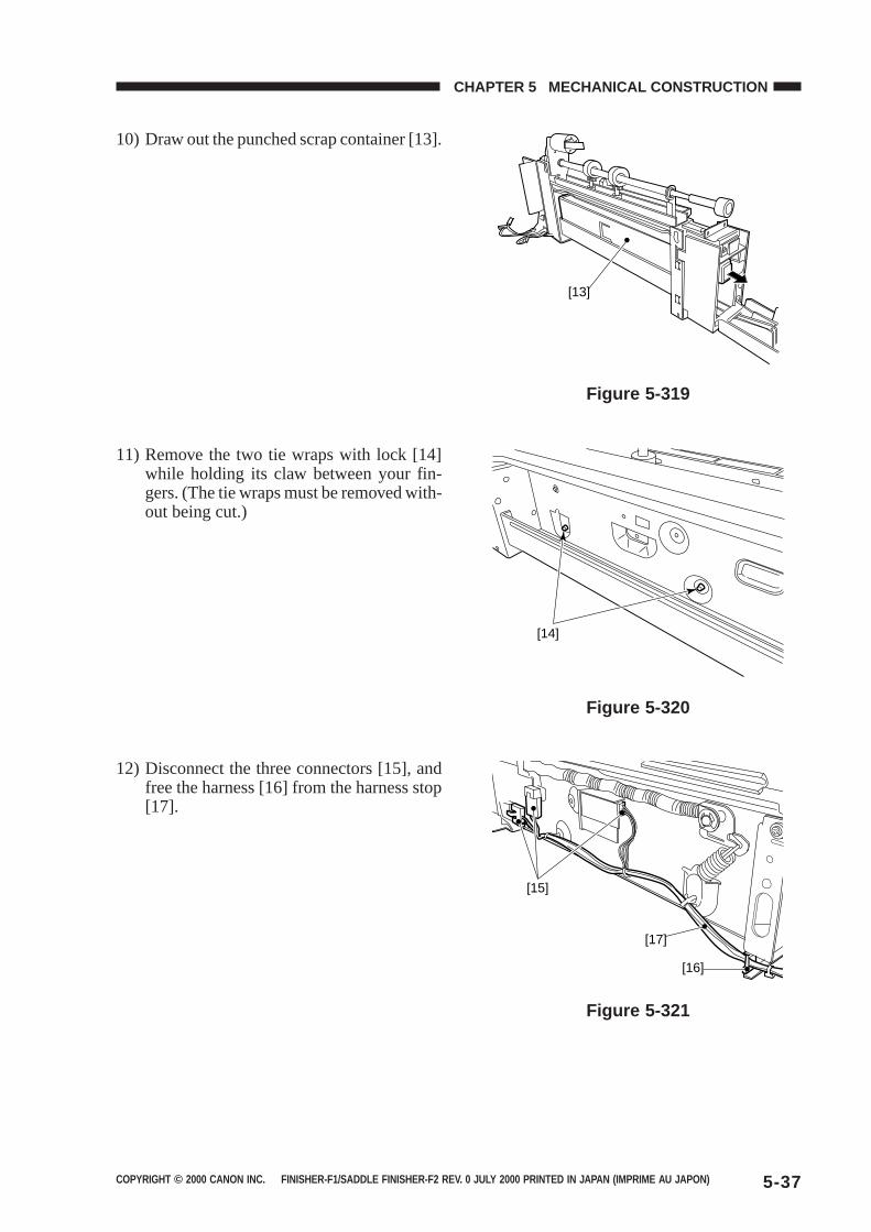
COPYRIGHT © 2000 CANON INC. FINISHER-F1/SADDLE FINISHER-F2 REV. 0 JULY 2000 PRINTED IN JAPAN (IMPRIME AU JAPON) 5-37
CHAPTER 5 MECHANICAL CONSTRUCTION
Figure 5-319
10) Draw out the punched scrap container [13].
Figure 5-321
12) Disconnect the three connectors [15], andfree the harness [16] from the harness stop[17].
Figure 5-320
11) Remove the two tie wraps with lock [14]while holding its claw between your fin-gers. (The tie wraps must be removed with-out being cut.)
[13]
[14]
[15]
[17]
[16]
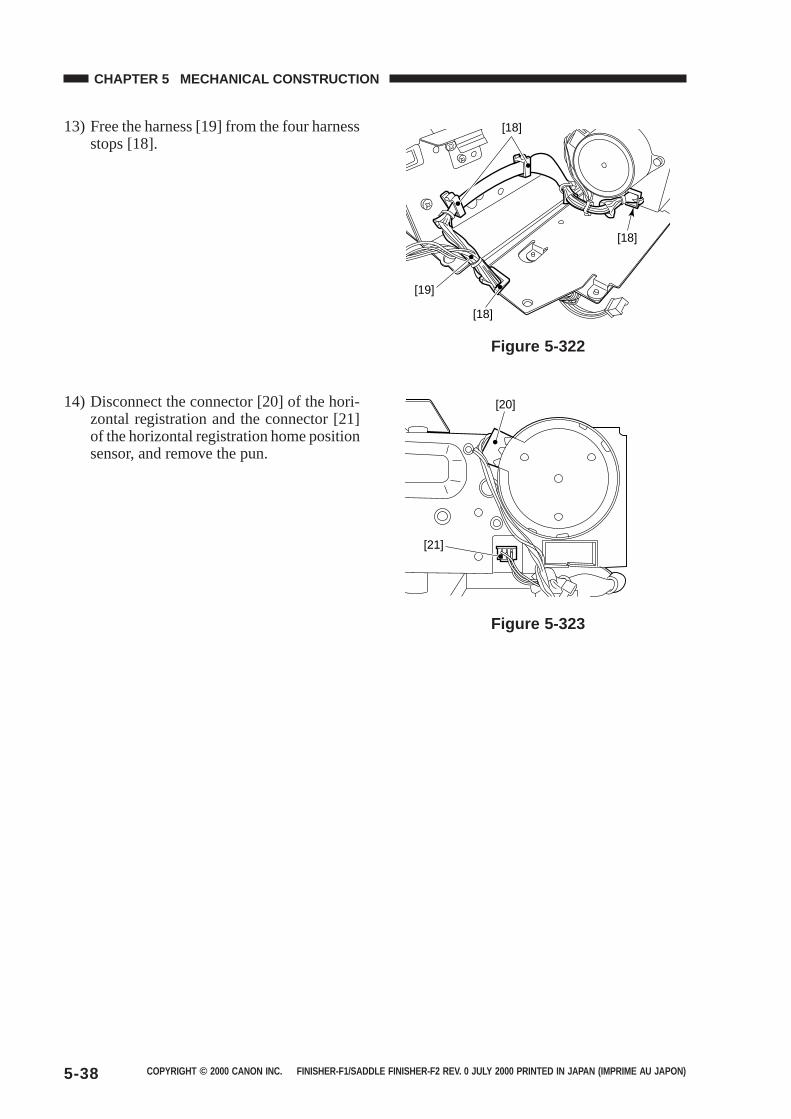
COPYRIGHT © 2000 CANON INC. FINISHER-F1/SADDLE FINISHER-F2 REV. 0 JULY 2000 PRINTED IN JAPAN (IMPRIME AU JAPON)5-38
CHAPTER 5 MECHANICAL CONSTRUCTION
Figure 5-322
13) Free the harness [19] from the four harnessstops [18].
Figure 5-323
14) Disconnect the connector [20] of the hori-zontal registration and the connector [21]of the horizontal registration home positionsensor, and remove the pun.
[19]
[18]
[18]
[18]
[21]
[20]
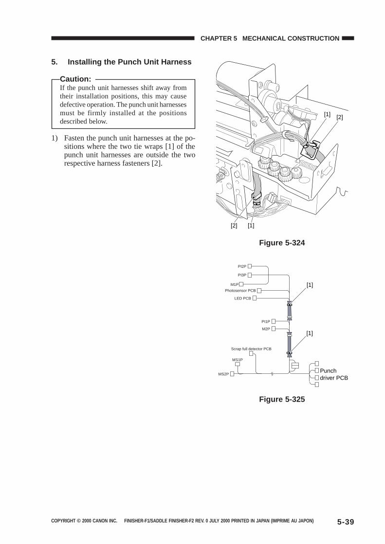
COPYRIGHT © 2000 CANON INC. FINISHER-F1/SADDLE FINISHER-F2 REV. 0 JULY 2000 PRINTED IN JAPAN (IMPRIME AU JAPON) 5-39
CHAPTER 5 MECHANICAL CONSTRUCTION
Figure 5-324
5. Installing the Punch Unit Harness
Caution:If the punch unit harnesses shift away fromtheir installation positions, this may causedefective operation. The punch unit harnessesmust be firmly installed at the positionsdescribed below.
1) Fasten the punch unit harnesses at the po-sitions where the two tie wraps [1] of thepunch unit harnesses are outside the tworespective harness fasteners [2].
Figure 5-325
[2][1]
[2] [1]
[1]
PI2P
PI3P
M1P
Photosensor PCB
LED PCB
PI1P
M2P
Scrap full detector PCB
MS1P
MS2P
[1]
Punch driver PCB
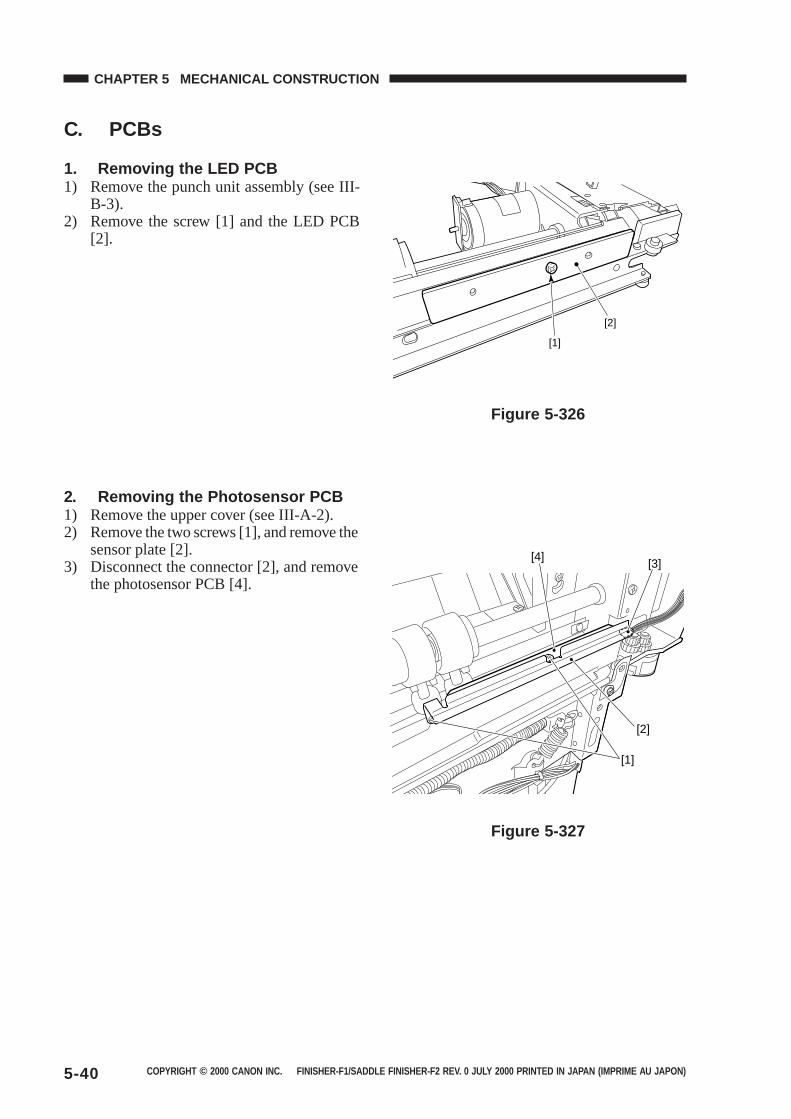
COPYRIGHT © 2000 CANON INC. FINISHER-F1/SADDLE FINISHER-F2 REV. 0 JULY 2000 PRINTED IN JAPAN (IMPRIME AU JAPON)5-40
CHAPTER 5 MECHANICAL CONSTRUCTION
C. PCBs
1. Removing the LED PCB1) Remove the punch unit assembly (see III-
B-3).2) Remove the screw [1] and the LED PCB
[2].
Figure 5-326
2. Removing the Photosensor PCB1) Remove the upper cover (see III-A-2).2) Remove the two screws [1], and remove the
sensor plate [2].3) Disconnect the connector [2], and remove
the photosensor PCB [4].
Figure 5-327
[2]
[1]
[1]
[2]
[3][4]
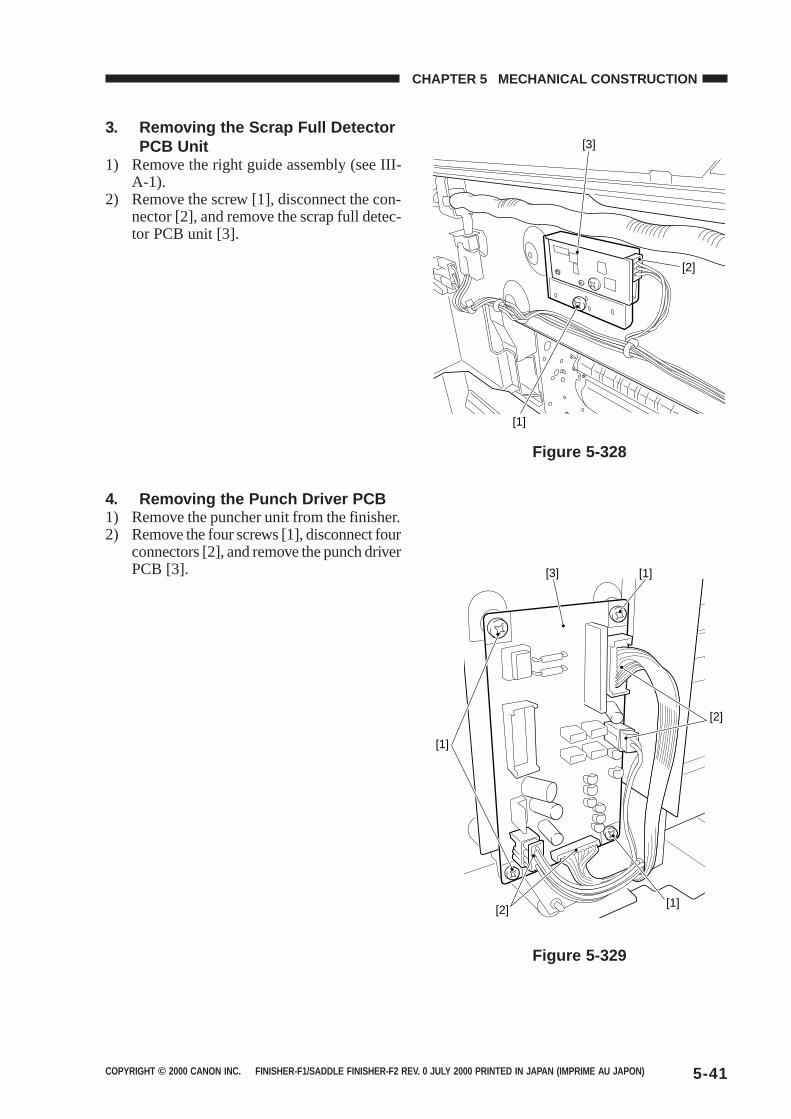
COPYRIGHT © 2000 CANON INC. FINISHER-F1/SADDLE FINISHER-F2 REV. 0 JULY 2000 PRINTED IN JAPAN (IMPRIME AU JAPON) 5-41
CHAPTER 5 MECHANICAL CONSTRUCTION
3. Removing the Scrap Full DetectorPCB Unit
1) Remove the right guide assembly (see III-A-1).
2) Remove the screw [1], disconnect the con-nector [2], and remove the scrap full detec-tor PCB unit [3].
4. Removing the Punch Driver PCB1) Remove the puncher unit from the finisher.2) Remove the four screws [1], disconnect four
connectors [2], and remove the punch driverPCB [3].
Figure 5-328
Figure 5-329
[3]
[2]
[1]
[3] [1]
[1]
[2]
[1]
[2]

COPYRIGHT © 2000 CANON INC. FINISHER-F1/SADDLE FINISHER-F2 REV. 0 JULY 2000 PRINTED IN JAPAN (IMPRIME AU JAPON)
CHAPTER 6
MAINTENANCE AND INSPECTION
I. PERIODICALLY REPLACEDPARTS ........................................6-1A. Finisher Unit .........................6-1B. Saddle Stitcher Unit .............6-1C. Puncher Unit (option) ...........6-1
II. CONSUMABLES ANDDURABLES ................................6-2A. Finisher Unit .........................6-2B. Saddle Stitcher Unit .............6-2C. Puncher Unit (option) ...........6-2
III. PERIODICAL SERVICING.........6-2

COPYRIGHT © 2000 CANON INC. FINISHER-F1/SADDLE FINISHER-F2 REV. 0 JULY 2000 PRINTED IN JAPAN (IMPRIME AU JAPON) 6-1
CHAPTER 6 MAINTENANCE AND INSPECTION
I. PERIODICALLY REPLACED PARTS
A. Finisher Unit
The finisher unit does not have parts that must be replaced on a periodical basis.
B. Saddle Stitcher Unit
The saddle stitcher unit does not have parts that must be replaced on a periodical basis.
C. Puncher Unit (option)
The puncher unit does not have parts that must be replaced on a periodical basis.
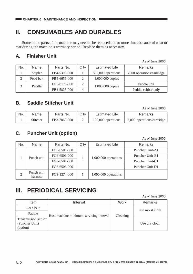
COPYRIGHT © 2000 CANON INC. FINISHER-F1/SADDLE FINISHER-F2 REV. 0 JULY 2000 PRINTED IN JAPAN (IMPRIME AU JAPON)6-2
CHAPTER 6 MAINTENANCE AND INSPECTION
II. CONSUMABLES AND DURABLES
Some of the parts of the machine may need to be replaced one or more times because of wear ortear during the machine’s warranty period. Replace them as necessary.
A. Finisher UnitAs of June 2000
No. Name Parts No. Q’ty Estimated Life Remarks
1 Stapler FB4-5390-000 1 500,000 operations 5,000 operations/cartridge
2 Feed belt FB4-6656-000 2 1,000,000 copies
3 PaddleFG5-8178-000 2
1,000,000 copiesPaddle unit
FB4-5825-000 4 Paddle rubber only
B. Saddle Stitcher UnitAs of June 2000
No. Name Parts No. Q’ty Estimated Life Remarks
1 Stitcher FB3-7860-000 2 100,000 operations 2,000 operations/cartridge
C. Puncher Unit (option)As of June 2000
No. Name Parts No. Q’ty Estimated Life Remarks
FG6-6500-000 Puncher Unit-A1
1 Punch unitFG6-6501-000
1 1,000,000 operationsPuncher Unit-B1
FG6-6502-000 Puncher Unit-C1
FG6-6503-000 Puncher Unit-D1
2Punch unit
FG3-1374-000 1 1,000,000 operationsharness
III. PERIODICAL SERVICINGAs of June 2000
Item Interval Work Remarks
Feed beltUse moist cloth
PaddleHost machine minimum servicing interval Cleaning
Transmission sensor(Puncher Unit) Use dry cloth(option)
COPYRIGHT © 2000 CANON INC. FINISHER-F1/SADDLE FINISHER-F2 REV. 0 JULY 2000 PRINTED IN JAPAN (IMPRIME AU JAPON)
CHAPTER 7
TROUBLESHOOTING
I. ADJUSTMENTS .........................7-1A. Electrical System
(finisher unit) .........................7-1B. Electrical System
(saddle stitcher unit) .............7-6C. Electrical System
(puncher unit (option)) ..........7-9II. ARRANGEMENT OF
ELECTRICAL PARTS.............. 7-11A. Finisher Unit ...................... 7-11B. Saddle Stitcher Unit .......... 7-17C. Puncher Unit (option) ........ 7-23D. Light-Emitting Diodes (LED)
and Check Pins by PCB .... 7-27
III. TROUBLESHOOTING ............ 7-29A. Finisher Unit ...................... 7-29B. Saddle Stitcher Unit .......... 7-39C. Puncher Unit (option) ........ 7-46
IV. SELF-DIAGNOSIS .................. 7-47A. Finisher Unit ...................... 7-47B. Saddle Stitcher Unit .......... 7-49C. Puncher Unit (option) ........ 7-51D. Alarm ................................. 7-52E. Host Machine I/O
Notations ........................... 7-54

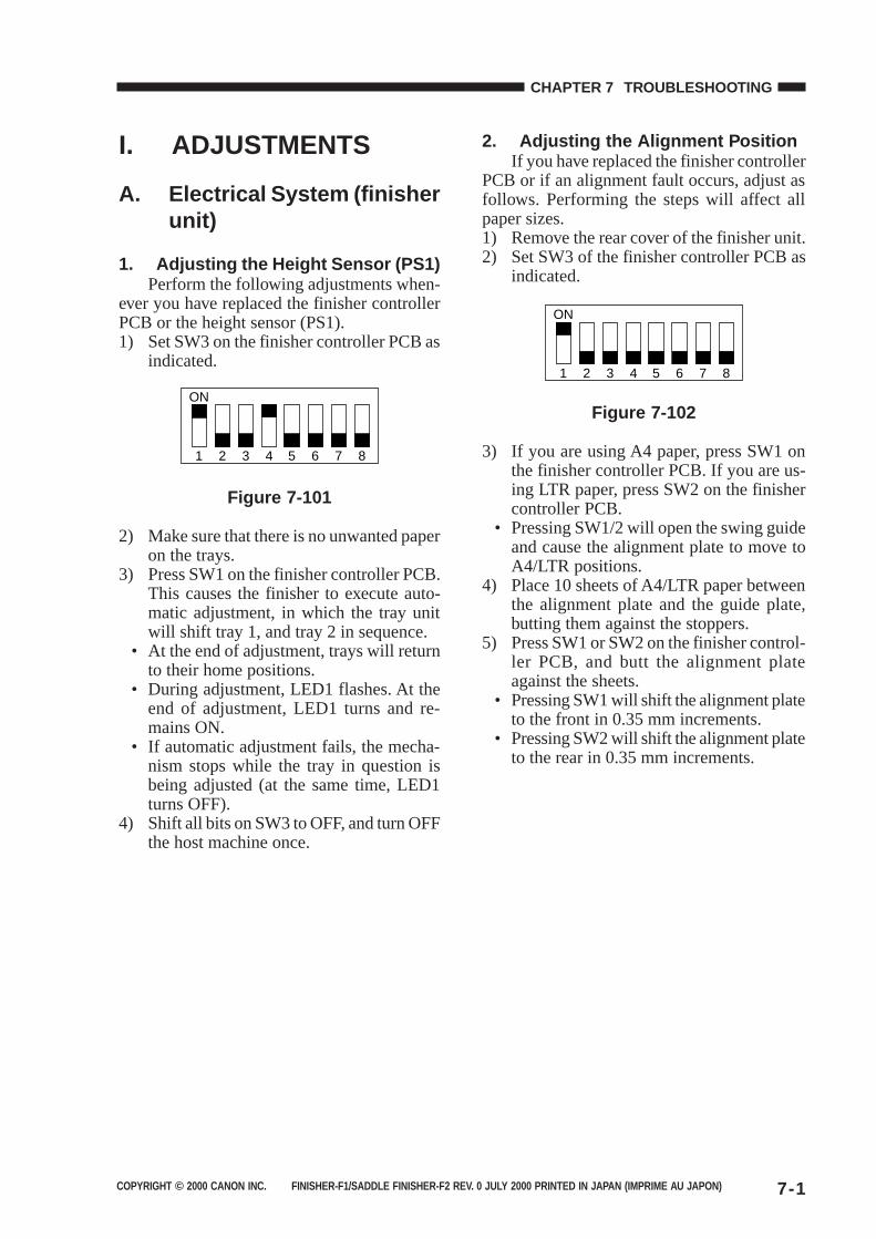
COPYRIGHT © 2000 CANON INC. FINISHER-F1/SADDLE FINISHER-F2 REV. 0 JULY 2000 PRINTED IN JAPAN (IMPRIME AU JAPON) 7-1
CHAPTER 7 TROUBLESHOOTING
I. ADJUSTMENTS
A. Electrical System (finisherunit)
1. Adjusting the Height Sensor (PS1)Perform the following adjustments when-
ever you have replaced the finisher controllerPCB or the height sensor (PS1).1) Set SW3 on the finisher controller PCB as
indicated.
ON
1 2 3 4 5 6 7 8
Figure 7-101
2) Make sure that there is no unwanted paperon the trays.
3) Press SW1 on the finisher controller PCB.This causes the finisher to execute auto-matic adjustment, in which the tray unitwill shift tray 1, and tray 2 in sequence.
• At the end of adjustment, trays will returnto their home positions.
• During adjustment, LED1 flashes. At theend of adjustment, LED1 turns and re-mains ON.
• If automatic adjustment fails, the mecha-nism stops while the tray in question isbeing adjusted (at the same time, LED1turns OFF).
4) Shift all bits on SW3 to OFF, and turn OFFthe host machine once.
2. Adjusting the Alignment PositionIf you have replaced the finisher controller
PCB or if an alignment fault occurs, adjust asfollows. Performing the steps will affect allpaper sizes.1) Remove the rear cover of the finisher unit.2) Set SW3 of the finisher controller PCB as
indicated.
ON
1 2 3 4 5 6 7 8
Figure 7-102
3) If you are using A4 paper, press SW1 onthe finisher controller PCB. If you are us-ing LTR paper, press SW2 on the finishercontroller PCB.
• Pressing SW1/2 will open the swing guideand cause the alignment plate to move toA4/LTR positions.
4) Place 10 sheets of A4/LTR paper betweenthe alignment plate and the guide plate,butting them against the stoppers.
5) Press SW1 or SW2 on the finisher control-ler PCB, and butt the alignment plateagainst the sheets.
• Pressing SW1 will shift the alignment plateto the front in 0.35 mm increments.
• Pressing SW2 will shift the alignment plateto the rear in 0.35 mm increments.
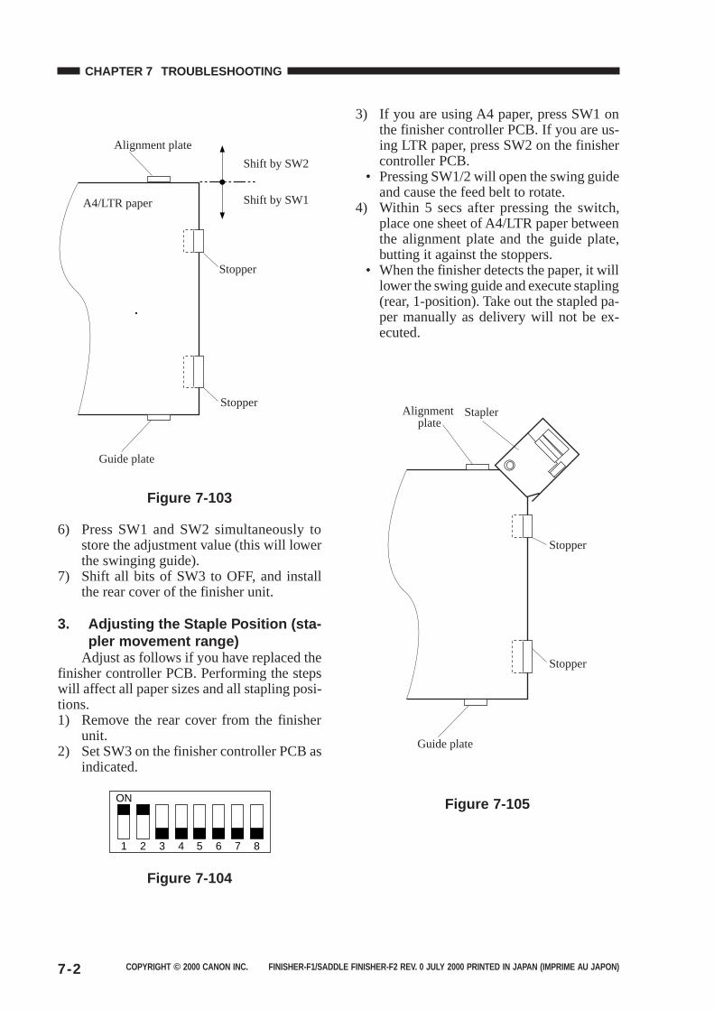
COPYRIGHT © 2000 CANON INC. FINISHER-F1/SADDLE FINISHER-F2 REV. 0 JULY 2000 PRINTED IN JAPAN (IMPRIME AU JAPON)7-2
CHAPTER 7 TROUBLESHOOTING
Stopper
Stopper
Guide plate
Alignment plate
A4/LTR paper
Shift by SW2
Shift by SW1
Figure 7-103
6) Press SW1 and SW2 simultaneously tostore the adjustment value (this will lowerthe swinging guide).
7) Shift all bits of SW3 to OFF, and installthe rear cover of the finisher unit.
3. Adjusting the Staple Position (sta-pler movement range)
Adjust as follows if you have replaced thefinisher controller PCB. Performing the stepswill affect all paper sizes and all stapling posi-tions.1) Remove the rear cover from the finisher
unit.2) Set SW3 on the finisher controller PCB as
indicated.
ON
1 2 3 4 5 6 7 8
Figure 7-104
3) If you are using A4 paper, press SW1 onthe finisher controller PCB. If you are us-ing LTR paper, press SW2 on the finishercontroller PCB.
• Pressing SW1/2 will open the swing guideand cause the feed belt to rotate.
4) Within 5 secs after pressing the switch,place one sheet of A4/LTR paper betweenthe alignment plate and the guide plate,butting it against the stoppers.
• When the finisher detects the paper, it willlower the swing guide and execute stapling(rear, 1-position). Take out the stapled pa-per manually as delivery will not be ex-ecuted.
Stopper
Guide plate
Alignment plate
Stopper
Stapler
Figure 7-105
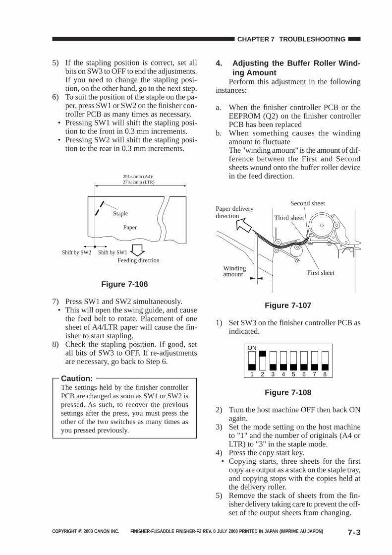
COPYRIGHT © 2000 CANON INC. FINISHER-F1/SADDLE FINISHER-F2 REV. 0 JULY 2000 PRINTED IN JAPAN (IMPRIME AU JAPON) 7-3
CHAPTER 7 TROUBLESHOOTING
5) If the stapling position is correct, set allbits on SW3 to OFF to end the adjustments.If you need to change the stapling posi-tion, on the other hand, go to the next step.
6) To suit the position of the staple on the pa-per, press SW1 or SW2 on the finisher con-troller PCB as many times as necessary.
• Pressing SW1 will shift the stapling posi-tion to the front in 0.3 mm increments.
• Pressing SW2 will shift the stapling posi-tion to the rear in 0.3 mm increments.
Shift by SW2 Shift by SW1Feeding direction
Staple
Paper
291±2mm (A4)/273±2mm (LTR)
Figure 7-106
7) Press SW1 and SW2 simultaneously.• This will open the swing guide, and cause
the feed belt to rotate. Placement of onesheet of A4/LTR paper will cause the fin-isher to start stapling.
8) Check the stapling position. If good, setall bits of SW3 to OFF. If re-adjustmentsare necessary, go back to Step 6.
Caution:The settings held by the finisher controllerPCB are changed as soon as SW1 or SW2 ispressed. As such, to recover the previoussettings after the press, you must press theother of the two switches as many times asyou pressed previously.
4. Adjusting the Buffer Roller Wind-ing Amount
Perform this adjustment in the followinginstances:
a. When the finisher controller PCB or theEEPROM (Q2) on the finisher controllerPCB has been replaced
b. When something causes the windingamount to fluctuateThe "winding amount" is the amount of dif-ference between the First and Secondsheets wound onto the buffer roller devicein the feed direction.
Paper delivery direction
First sheet
Second sheet
Third sheet
Windingamount
Figure 7-107
1) Set SW3 on the finisher controller PCB asindicated.
ON
1 2 3 4 5 6 7 8
Figure 7-108
2) Turn the host machine OFF then back ONagain.
3) Set the mode setting on the host machineto "1" and the number of originals (A4 orLTR) to "3" in the staple mode.
4) Press the copy start key.• Copying starts, three sheets for the first
copy are output as a stack on the staple tray,and copying stops with the copies held atthe delivery roller.
5) Remove the stack of sheets from the fin-isher delivery taking care to prevent the off-set of the output sheets from changing.
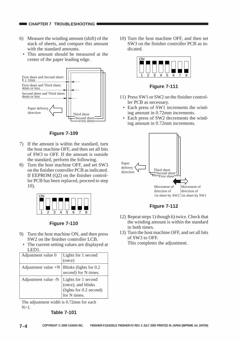
COPYRIGHT © 2000 CANON INC. FINISHER-F1/SADDLE FINISHER-F2 REV. 0 JULY 2000 PRINTED IN JAPAN (IMPRIME AU JAPON)7-4
CHAPTER 7 TROUBLESHOOTING
6) Measure the winding amount (shift) of thestack of sheets, and compare this amountwith the standard amounts.
• This amount should be measured at thecenter of the paper leading edge.
Third sheet
First sheetSecond sheet
Paper delivery direction
First sheet and Second sheet: 0 ± 1mm
First sheet and Third sheet: 4mm or less
Second sheet and Third sheet: 4mm or less
Figure 7-109
7) If the amount is within the standard, turnthe host machine OFF, and then set all bitsof SW3 to OFF. If the amount is outsidethe standard, perform the following.
8) Turn the host machine OFF, and set SW3on the finisher controller PCB as indicated.If EEPROM (Q2) on the finisher control-ler PCB has been replaced, proceed to step10).
ON
1 2 3 4 5 6 7 8
Figure 7-110
9) Turn the host machine ON, and then pressSW2 on the finisher controller LCB.
• The current setting values are displayed atLED1.
Adjustment value 0 Lights for 1 second(once)
Adjustment value +N Blinks (lights for 0.2second) for N times.
Adjustment value -N Lights for 1 second(once), and blinks(lights for 0.2 second)for N times.
The adjustment width is 0.72mm for eachN=1.
Table 7-101
10) Turn the host machine OFF, and then setSW3 on the finisher controller PCB as in-dicated.
ON
1 2 3 4 5 6 7 8
Figure 7-111
11) Press SW1 or SW2 on the finisher control-ler PCB as necessary.
• Each press of SW1 increments the wind-ing amount in 0.72mm increments.
• Each press of SW2 decrements the wind-ing amount in 0.72mm increments.
Third sheet
First sheetSecond sheet
Paperdeliverydirection
Movement ofdirection of1st sheet by SW1
Movement ofdirection of1st sheet by SW2
Figure 7-112
12) Repeat steps 1) though 6) twice. Check thatthe winding amount is within the standardin both times.
13) Turn the host machine OFF, and set all bitsof SW3 to OFF.This completes the adjustment.
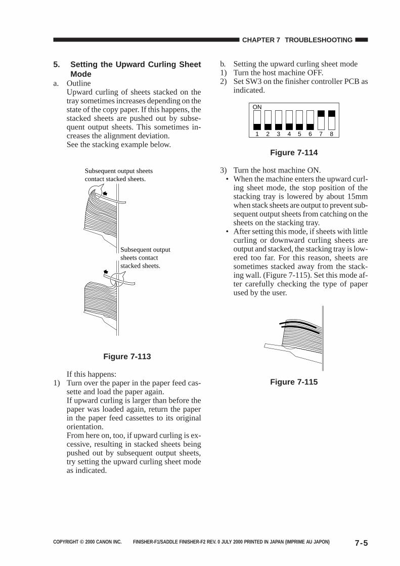
COPYRIGHT © 2000 CANON INC. FINISHER-F1/SADDLE FINISHER-F2 REV. 0 JULY 2000 PRINTED IN JAPAN (IMPRIME AU JAPON) 7-5
CHAPTER 7 TROUBLESHOOTING
5. Setting the Upward Curling SheetMode
a. OutlineUpward curling of sheets stacked on thetray sometimes increases depending on thestate of the copy paper. If this happens, thestacked sheets are pushed out by subse-quent output sheets. This sometimes in-creases the alignment deviation.See the stacking example below.
Subsequent output sheetscontact stacked sheets.
Subsequent outputsheets contactstacked sheets.
Figure 7-113
If this happens:1) Turn over the paper in the paper feed cas-
sette and load the paper again.If upward curling is larger than before thepaper was loaded again, return the paperin the paper feed cassettes to its originalorientation.From here on, too, if upward curling is ex-cessive, resulting in stacked sheets beingpushed out by subsequent output sheets,try setting the upward curling sheet modeas indicated.
b. Setting the upward curling sheet mode1) Turn the host machine OFF.2) Set SW3 on the finisher controller PCB as
indicated.
ON
1 2 3 4 5 6 7 8
Figure 7-114
3) Turn the host machine ON.• When the machine enters the upward curl-
ing sheet mode, the stop position of thestacking tray is lowered by about 15mmwhen stack sheets are output to prevent sub-sequent output sheets from catching on thesheets on the stacking tray.
• After setting this mode, if sheets with littlecurling or downward curling sheets areoutput and stacked, the stacking tray is low-ered too far. For this reason, sheets aresometimes stacked away from the stack-ing wall. (Figure 7-115). Set this mode af-ter carefully checking the type of paperused by the user.
Figure 7-115
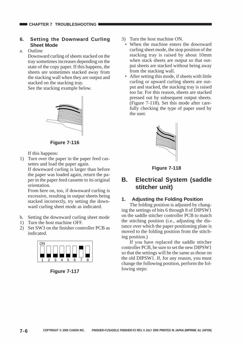
COPYRIGHT © 2000 CANON INC. FINISHER-F1/SADDLE FINISHER-F2 REV. 0 JULY 2000 PRINTED IN JAPAN (IMPRIME AU JAPON)7-6
CHAPTER 7 TROUBLESHOOTING
6. Setting the Downward CurlingSheet Mode
a. OutlineDownward curling of sheets stacked on thetray sometimes increases depending on thestate of the copy paper. If this happens, thesheets are sometimes stacked away fromthe stacking wall when they are output andstacked on the stacking tray.See the stacking example below.
Figure 7-116
If this happens:1) Turn over the paper in the paper feed cas-
settes and load the paper again.If downward curling is larger than beforethe paper was loaded again, return the pa-per in the paper feed cassette to its originalorientation.From here on, too, if downward curling isexcessive, resulting in output sheets beingstacked incorrectly, try setting the down-ward curling sheet mode as indicated.
b. Setting the downward curling sheet mode1) Turn the host machine OFF.2) Set SW3 on the finisher controller PCB as
indicated.
ON
1 2 3 4 5 6 7 8
Figure 7-117
3) Turn the host machine ON.• When the machine enters the downward
curling sheet mode, the stop position of thestacking tray is raised by about 10mmwhen stack sheets are output so that out-put sheets are stacked without being awayfrom the stacking wall.
• After setting this mode, if sheets with littlecurling or upward curling sheets are out-put and stacked, the stacking tray is raisedtoo far. For this reason, sheets are stackedpressed out by subsequent output sheets.(Figure 7-118). Set this mode after care-fully checking the type of paper used bythe user.
Figure 7-118
B. Electrical System (saddlestitcher unit)
1. Adjusting the Folding PositionThe folding position is adjusted by chang-
ing the settings of bits 6 through 8 of DIPSW1on the saddle stitcher controller PCB to matchthe stitching position (i.e., adjusting the dis-tance over which the paper positioning plate ismoved to the folding position from the stitch-ing position.)
If you have replaced the saddle stitchercontroller PCB, be sure to set the new DIPSW1so that the settings will be the same as those onthe old DIPSW1. If, for any reason, you mustchange the following position, perform the fol-lowing steps:
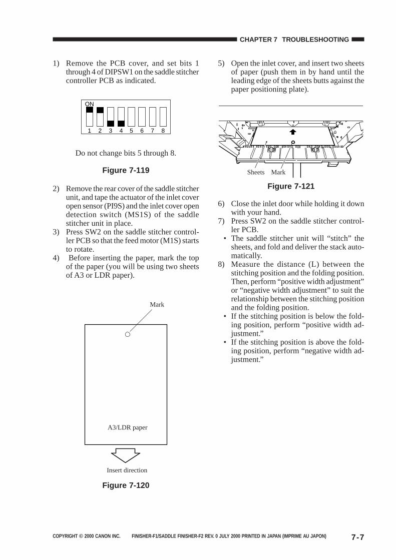
COPYRIGHT © 2000 CANON INC. FINISHER-F1/SADDLE FINISHER-F2 REV. 0 JULY 2000 PRINTED IN JAPAN (IMPRIME AU JAPON) 7-7
CHAPTER 7 TROUBLESHOOTING
1) Remove the PCB cover, and set bits 1through 4 of DIPSW1 on the saddle stitchercontroller PCB as indicated.
ON
1 2 3 4 5 6 7 8
Do not change bits 5 through 8.
Figure 7-119
2) Remove the rear cover of the saddle stitcherunit, and tape the actuator of the inlet coveropen sensor (PI9S) and the inlet cover opendetection switch (MS1S) of the saddlestitcher unit in place.
3) Press SW2 on the saddle stitcher control-ler PCB so that the feed motor (M1S) startsto rotate.
4) Before inserting the paper, mark the topof the paper (you will be using two sheetsof A3 or LDR paper).
Mark
A3/LDR paper
Insert direction
Figure 7-120
5) Open the inlet cover, and insert two sheetsof paper (push them in by hand until theleading edge of the sheets butts against thepaper positioning plate).
Sheets Mark
Figure 7-121
6) Close the inlet door while holding it downwith your hand.
7) Press SW2 on the saddle stitcher control-ler PCB.
• The saddle stitcher unit will “stitch” thesheets, and fold and deliver the stack auto-matically.
8) Measure the distance (L) between thestitching position and the folding position.Then, perform “positive width adjustment”or “negative width adjustment” to suit therelationship between the stitching positionand the folding position.
• If the stitching position is below the fold-ing position, perform “positive width ad-justment.”
• If the stitching position is above the fold-ing position, perform “negative width ad-justment.”
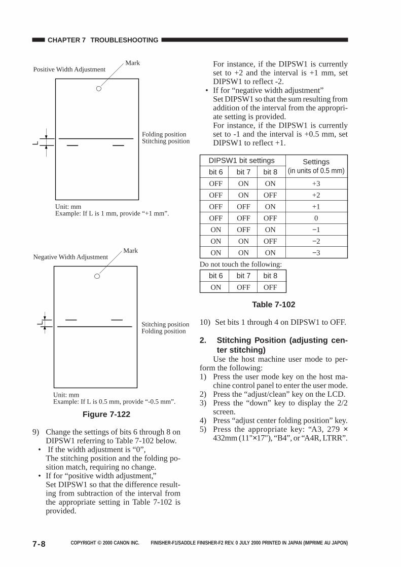
COPYRIGHT © 2000 CANON INC. FINISHER-F1/SADDLE FINISHER-F2 REV. 0 JULY 2000 PRINTED IN JAPAN (IMPRIME AU JAPON)7-8
CHAPTER 7 TROUBLESHOOTING
Mark
Mark
Folding positionStitching position
Stitching positionFolding position
Positive Width Adjustment
Negative Width Adjustment
Unit: mmExample: If L is 1 mm, provide “+1 mm”.
Unit: mmExample: If L is 0.5 mm, provide “-0.5 mm”.
Figure 7-122
9) Change the settings of bits 6 through 8 onDIPSW1 referring to Table 7-102 below.
• If the width adjustment is “0”,The stitching position and the folding po-sition match, requiring no change.
• If for “positive width adjustment,”Set DIPSW1 so that the difference result-ing from subtraction of the interval fromthe appropriate setting in Table 7-102 isprovided.
For instance, if the DIPSW1 is currentlyset to +2 and the interval is +1 mm, setDIPSW1 to reflect -2.
• If for “negative width adjustment”Set DIPSW1 so that the sum resulting fromaddition of the interval from the appropri-ate setting is provided.For instance, if the DIPSW1 is currentlyset to -1 and the interval is +0.5 mm, setDIPSW1 to reflect +1.
DIPSW1 bit settings Settingsbit 6 bit 7 bit 8 (in units of 0.5 mm)
OFF ON ON +3
OFF ON OFF +2
OFF OFF ON +1
OFF OFF OFF 0
ON OFF ON −1
ON ON OFF −2
ON ON ON −3
Do not touch the following:
bit 6 bit 7 bit 8
ON OFF OFF
Table 7-102
10) Set bits 1 through 4 on DIPSW1 to OFF.
2. Stitching Position (adjusting cen-ter stitching)
Use the host machine user mode to per-form the following:1) Press the user mode key on the host ma-
chine control panel to enter the user mode.2) Press the “adjust/clean” key on the LCD.3) Press the “down” key to display the 2/2
screen.4) Press “adjust center folding position” key.5) Press the appropriate key: “A3, 279 ×
432mm (11"×17"), “B4”, or “A4R, LTRR”.
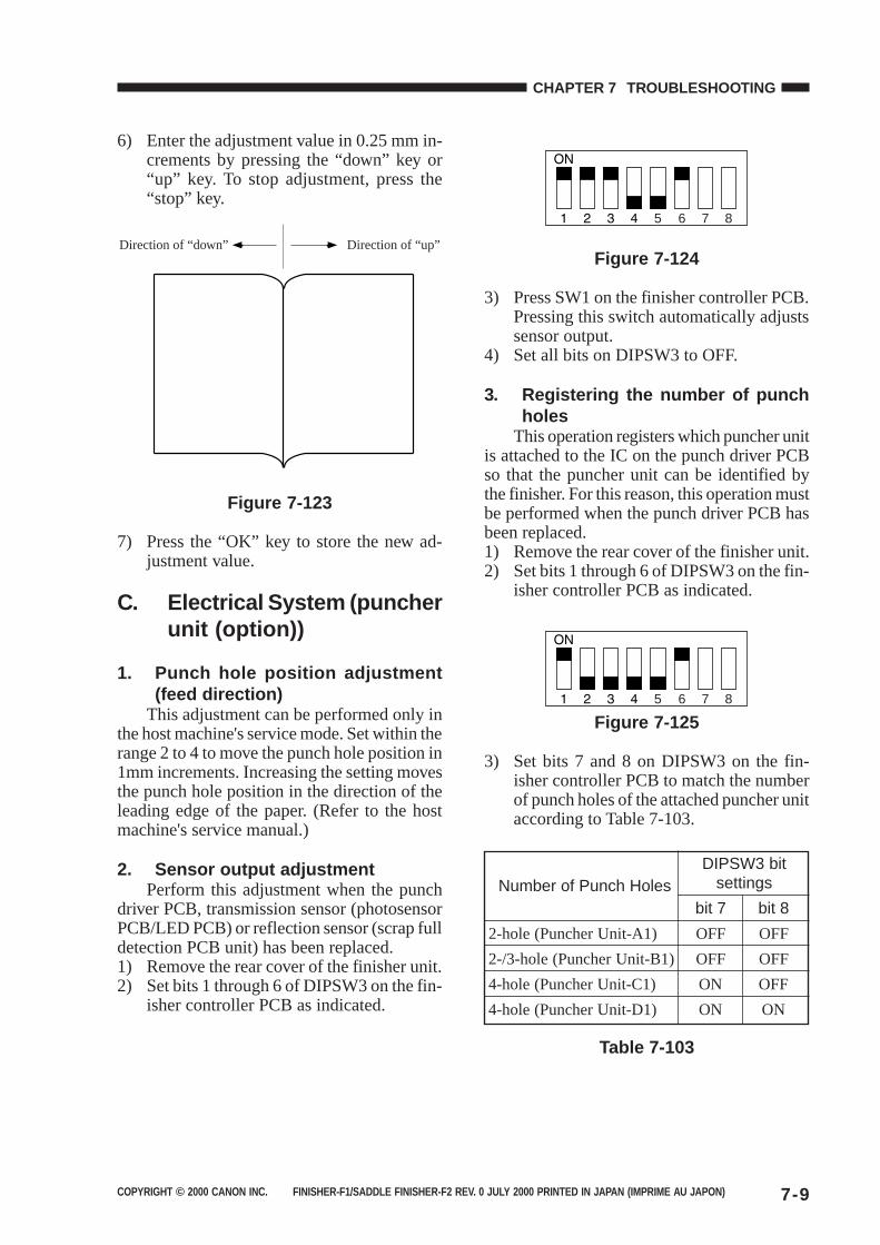
COPYRIGHT © 2000 CANON INC. FINISHER-F1/SADDLE FINISHER-F2 REV. 0 JULY 2000 PRINTED IN JAPAN (IMPRIME AU JAPON) 7-9
CHAPTER 7 TROUBLESHOOTING
6) Enter the adjustment value in 0.25 mm in-crements by pressing the “down” key or“up” key. To stop adjustment, press the“stop” key.
Direction of “up”Direction of “down”
Figure 7-123
7) Press the “OK” key to store the new ad-justment value.
C. Electrical System (puncherunit (option))
1. Punch hole position adjustment(feed direction)
This adjustment can be performed only inthe host machine's service mode. Set within therange 2 to 4 to move the punch hole position in1mm increments. Increasing the setting movesthe punch hole position in the direction of theleading edge of the paper. (Refer to the hostmachine's service manual.)
2. Sensor output adjustmentPerform this adjustment when the punch
driver PCB, transmission sensor (photosensorPCB/LED PCB) or reflection sensor (scrap fulldetection PCB unit) has been replaced.1) Remove the rear cover of the finisher unit.2) Set bits 1 through 6 of DIPSW3 on the fin-
isher controller PCB as indicated.
5 6 7 8
Figure 7-124
3) Press SW1 on the finisher controller PCB.Pressing this switch automatically adjustssensor output.
4) Set all bits on DIPSW3 to OFF.
3. Registering the number of punchholes
This operation registers which puncher unitis attached to the IC on the punch driver PCBso that the puncher unit can be identified bythe finisher. For this reason, this operation mustbe performed when the punch driver PCB hasbeen replaced.1) Remove the rear cover of the finisher unit.2) Set bits 1 through 6 of DIPSW3 on the fin-
isher controller PCB as indicated.
5 6 7 8
Figure 7-125
3) Set bits 7 and 8 on DIPSW3 on the fin-isher controller PCB to match the numberof punch holes of the attached puncher unitaccording to Table 7-103.
DIPSW3 bitNumber of Punch Holes settings
bit 7 bit 8
2-hole (Puncher Unit-A1) OFF OFF
2-/3-hole (Puncher Unit-B1) OFF OFF
4-hole (Puncher Unit-C1) ON OFF
4-hole (Puncher Unit-D1) ON ON
Table 7-103
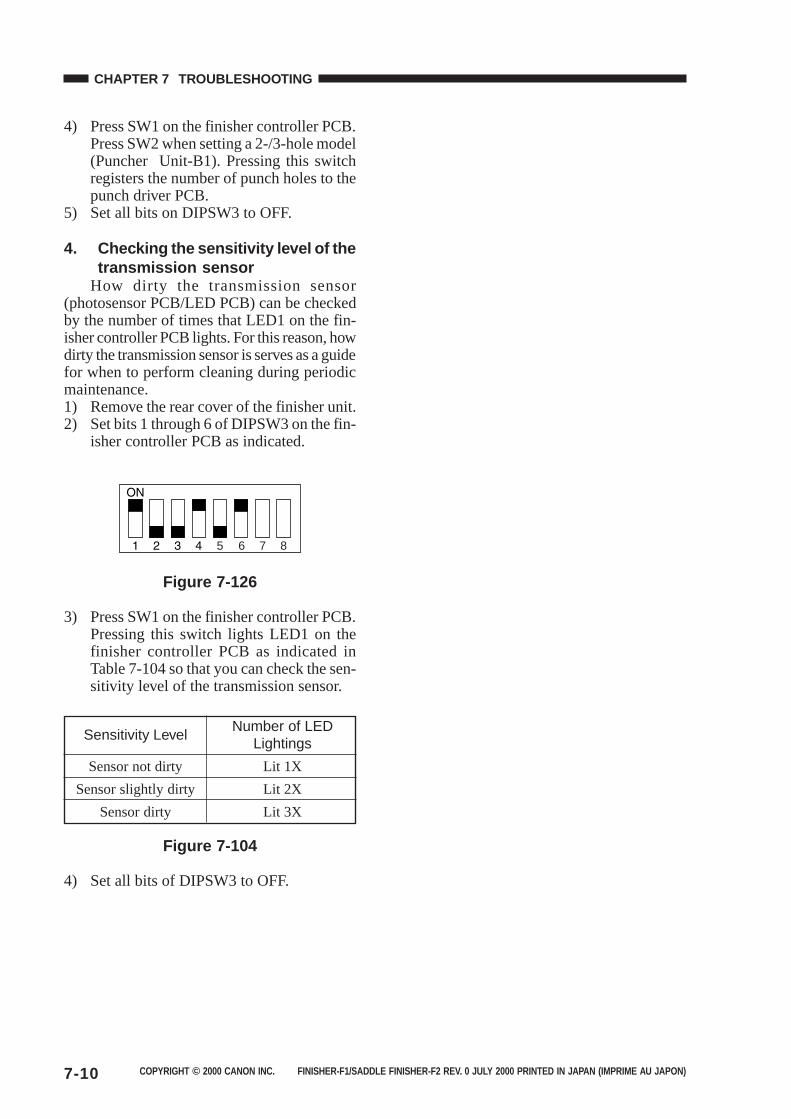
COPYRIGHT © 2000 CANON INC. FINISHER-F1/SADDLE FINISHER-F2 REV. 0 JULY 2000 PRINTED IN JAPAN (IMPRIME AU JAPON)7-10
CHAPTER 7 TROUBLESHOOTING
4) Press SW1 on the finisher controller PCB.Press SW2 when setting a 2-/3-hole model(Puncher Unit-B1). Pressing this switchregisters the number of punch holes to thepunch driver PCB.
5) Set all bits on DIPSW3 to OFF.
4. Checking the sensitivity level of thetransmission sensor
How dirty the transmission sensor(photosensor PCB/LED PCB) can be checkedby the number of times that LED1 on the fin-isher controller PCB lights. For this reason, howdirty the transmission sensor is serves as a guidefor when to perform cleaning during periodicmaintenance.1) Remove the rear cover of the finisher unit.2) Set bits 1 through 6 of DIPSW3 on the fin-
isher controller PCB as indicated.
5 6 7 8
Figure 7-126
3) Press SW1 on the finisher controller PCB.Pressing this switch lights LED1 on thefinisher controller PCB as indicated inTable 7-104 so that you can check the sen-sitivity level of the transmission sensor.
Sensitivity LevelNumber of LED
Lightings
Sensor not dirty Lit 1X
Sensor slightly dirty Lit 2X
Sensor dirty Lit 3X
Figure 7-104
4) Set all bits of DIPSW3 to OFF.
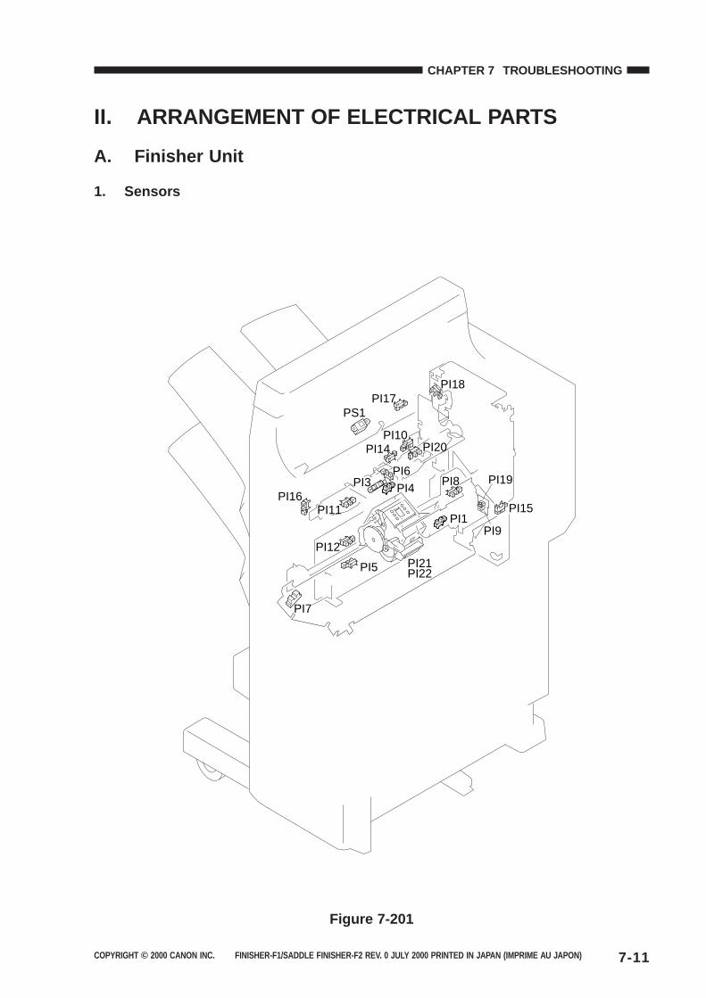
COPYRIGHT © 2000 CANON INC. FINISHER-F1/SADDLE FINISHER-F2 REV. 0 JULY 2000 PRINTED IN JAPAN (IMPRIME AU JAPON) 7-11
CHAPTER 7 TROUBLESHOOTING
II. ARRANGEMENT OF ELECTRICAL PARTS
A. Finisher Unit
1. Sensors
PI11
PS1PI17
PI1
PI18
PI10PI20PI14
PI6
PI4PI3PI16
PI12
PI5
PI7
PI15
PI19
PI9
PI8
PI21PI22
Figure 7-201
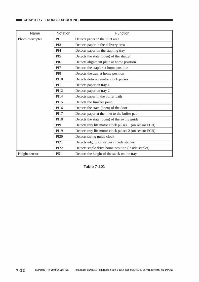
COPYRIGHT © 2000 CANON INC. FINISHER-F1/SADDLE FINISHER-F2 REV. 0 JULY 2000 PRINTED IN JAPAN (IMPRIME AU JAPON)7-12
CHAPTER 7 TROUBLESHOOTING
Name Notation Function
Photointerrupter PI1 Detects paper in the inlet area
PI3 Detects paper in the delivery area
PI4 Detects paper on the stapling tray
PI5 Detects the state (open) of the shutter
PI6 Detects alignment plate at home position
PI7 Detects the stapler at home position
PI8 Detects the tray at home position
PI10 Detects delivery motor clock pulses
PI11 Detects paper on tray 1
PI12 Detects paper on tray 2
PI14 Detects paper in the buffer path
PI15 Detects the finisher joint
PI16 Detects the state (open) of the door
PI17 Detects paper at the inlet to the buffer path
PI18 Detects the state (open) of the swing guide
PI9 Detects tray lift motor clock pulses 1 (on sensor PCB)
PI19 Detects tray lift motor clock pulses 2 (on sensor PCB)
PI20 Detects swing guide clock
PI21 Detects edging of staples (inside stapler)
PI22 Detects staple drive home position (inside stapler)
Height sensor PS1 Detects the height of the stack on the tray
Table 7-201
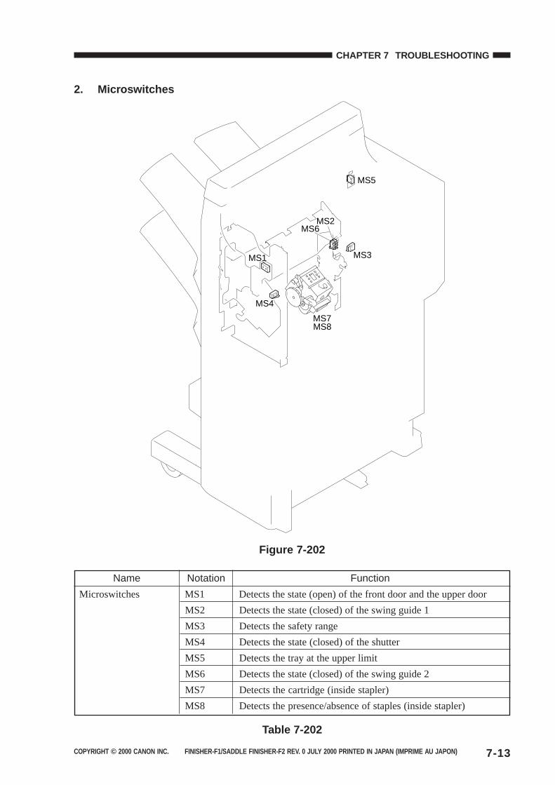
COPYRIGHT © 2000 CANON INC. FINISHER-F1/SADDLE FINISHER-F2 REV. 0 JULY 2000 PRINTED IN JAPAN (IMPRIME AU JAPON) 7-13
CHAPTER 7 TROUBLESHOOTING
2. Microswitches
MS1
MS4
MS3
MS5
MS6MS2
MS7MS8
Figure 7-202
Name Notation Function
Microswitches MS1 Detects the state (open) of the front door and the upper door
MS2 Detects the state (closed) of the swing guide 1
MS3 Detects the safety range
MS4 Detects the state (closed) of the shutter
MS5 Detects the tray at the upper limit
MS6 Detects the state (closed) of the swing guide 2
MS7 Detects the cartridge (inside stapler)
MS8 Detects the presence/absence of staples (inside stapler)
Table 7-202
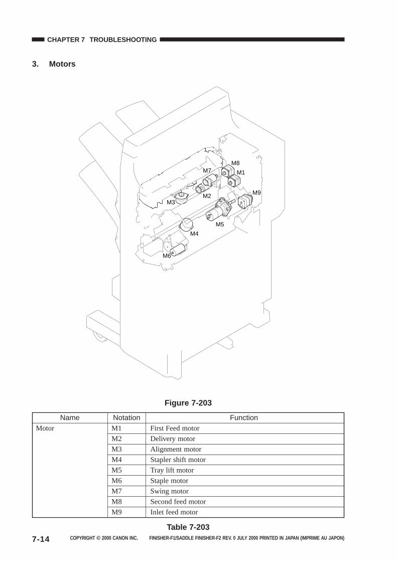
COPYRIGHT © 2000 CANON INC. FINISHER-F1/SADDLE FINISHER-F2 REV. 0 JULY 2000 PRINTED IN JAPAN (IMPRIME AU JAPON)7-14
CHAPTER 7 TROUBLESHOOTING
3. Motors
M1
M9
M8
M2
M7
M3
M4
M5
M6
Figure 7-203
Name Notation FunctionMotor M1 First Feed motor
M2 Delivery motor
M3 Alignment motor
M4 Stapler shift motor
M5 Tray lift motor
M6 Staple motor
M7 Swing motor
M8 Second feed motor
M9 Inlet feed motor
Table 7-203
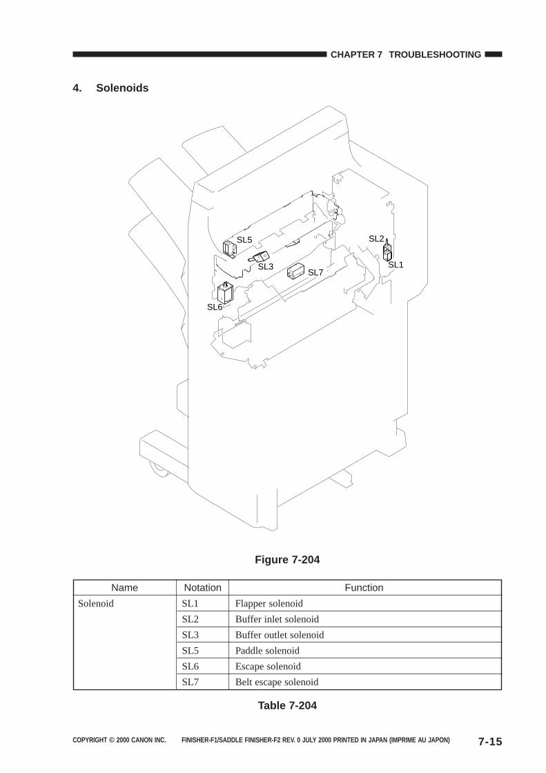
COPYRIGHT © 2000 CANON INC. FINISHER-F1/SADDLE FINISHER-F2 REV. 0 JULY 2000 PRINTED IN JAPAN (IMPRIME AU JAPON) 7-15
CHAPTER 7 TROUBLESHOOTING
4. Solenoids
SL2
SL3 SL1
SL6
SL5
SL7
Figure 7-204
Name Notation Function
Solenoid SL1 Flapper solenoid
SL2 Buffer inlet solenoid
SL3 Buffer outlet solenoid
SL5 Paddle solenoid
SL6 Escape solenoid
SL7 Belt escape solenoid
Table 7-204
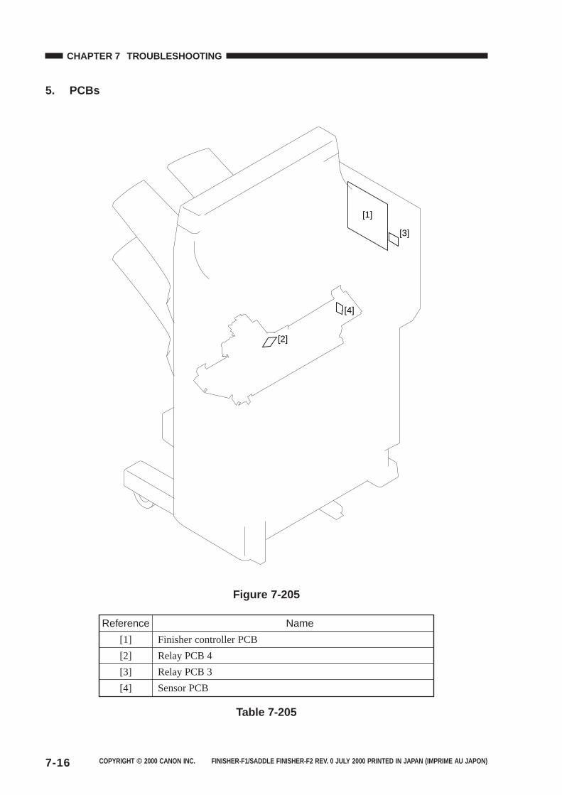
COPYRIGHT © 2000 CANON INC. FINISHER-F1/SADDLE FINISHER-F2 REV. 0 JULY 2000 PRINTED IN JAPAN (IMPRIME AU JAPON)7-16
CHAPTER 7 TROUBLESHOOTING
5. PCBs
[1]
[3]
[2]
[4]
Figure 7-205
Reference Name
[1] Finisher controller PCB
[2] Relay PCB 4
[3] Relay PCB 3
[4] Sensor PCB
Table 7-205
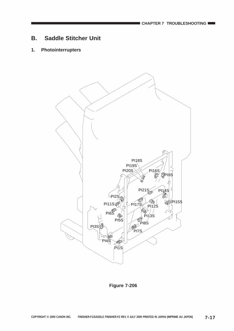
COPYRIGHT © 2000 CANON INC. FINISHER-F1/SADDLE FINISHER-F2 REV. 0 JULY 2000 PRINTED IN JAPAN (IMPRIME AU JAPON) 7-17
CHAPTER 7 TROUBLESHOOTING
B. Saddle Stitcher Unit
1. Photointerrupters
PI11S
PI9S
PI8S
PI7S
PI6SPI13S
PI4S
PI3S
PI2S
PI18SPI19S
PI20S
PI1S
PI12S
PI5S
PI14S
PI15S
PI16S
PI17S
PI21S
Figure 7-206
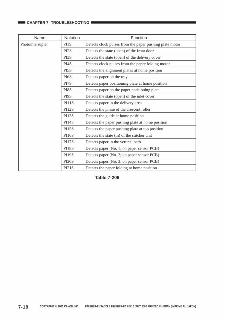
COPYRIGHT © 2000 CANON INC. FINISHER-F1/SADDLE FINISHER-F2 REV. 0 JULY 2000 PRINTED IN JAPAN (IMPRIME AU JAPON)7-18
CHAPTER 7 TROUBLESHOOTING
Name Notation Function
Photointerrupter PI1S Detects clock pulses from the paper pushing plate motor
PI2S Detects the state (open) of the front door
PI3S Detects the state (open) of the delivery cover
PI4S Detects clock pulses from the paper folding motor
PI5S Detects the alignment plates at home position
PI6S Detects paper on the tray
PI7S Detects paper positioning plate at home position
PI8S Detects paper on the paper positioning plate
PI9S Detects the state (open) of the inlet cover
PI11S Detects paper in the delivery area
PI12S Detects the phase of the crescent roller
PI13S Detects the guide at home position
PI14S Detects the paper pushing plate at home position
PI15S Detects the paper pushing plate at top position
PI16S Detects the state (in) of the stitcher unit
PI17S Detects paper in the vertical path
PI18S Detects paper (No. 1; on paper sensor PCB)
PI19S Detects paper (No. 2; on paper sensor PCB)
PI20S Detects paper (No. 3; on paper sensor PCB)
PI21S Detects the paper folding at home position
Table 7-206
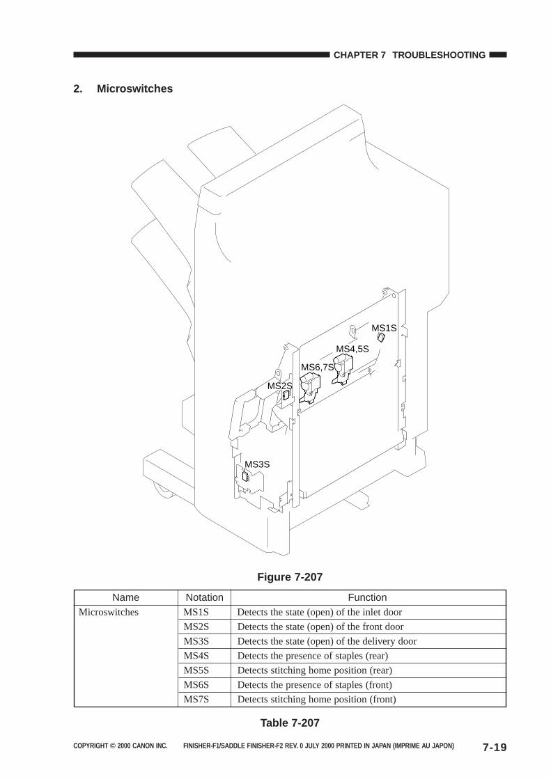
COPYRIGHT © 2000 CANON INC. FINISHER-F1/SADDLE FINISHER-F2 REV. 0 JULY 2000 PRINTED IN JAPAN (IMPRIME AU JAPON) 7-19
CHAPTER 7 TROUBLESHOOTING
2. Microswitches
MS2S
MS1S
MS3S
MS4,5S
MS6,7S
Figure 7-207
Name Notation FunctionMicroswitches MS1S Detects the state (open) of the inlet door
MS2S Detects the state (open) of the front door
MS3S Detects the state (open) of the delivery door
MS4S Detects the presence of staples (rear)
MS5S Detects stitching home position (rear)
MS6S Detects the presence of staples (front)
MS7S Detects stitching home position (front)
Table 7-207
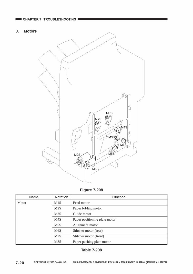
COPYRIGHT © 2000 CANON INC. FINISHER-F1/SADDLE FINISHER-F2 REV. 0 JULY 2000 PRINTED IN JAPAN (IMPRIME AU JAPON)7-20
CHAPTER 7 TROUBLESHOOTING
3. Motors
M7S
M8S
M2S
M1S
M4S
M5S
M3S
M6S
Figure 7-208
Name Notation Function
Motor M1S Feed motor
M2S Paper folding motor
M3S Guide motor
M4S Paper positioning plate motor
M5S Alignment motor
M6S Stitcher motor (rear)
M7S Stitcher motor (front)
M8S Paper pushing plate motor
Table 7-208
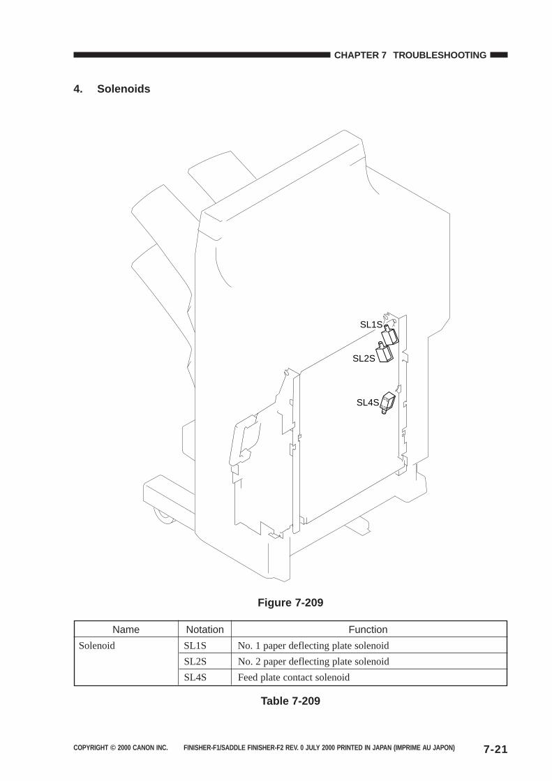
COPYRIGHT © 2000 CANON INC. FINISHER-F1/SADDLE FINISHER-F2 REV. 0 JULY 2000 PRINTED IN JAPAN (IMPRIME AU JAPON) 7-21
CHAPTER 7 TROUBLESHOOTING
4. Solenoids
SL1S
SL2S
SL4S
Figure 7-209
Name Notation Function
Solenoid SL1S No. 1 paper deflecting plate solenoid
SL2S No. 2 paper deflecting plate solenoid
SL4S Feed plate contact solenoid
Table 7-209
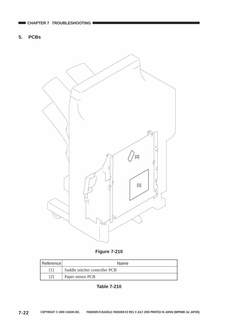
COPYRIGHT © 2000 CANON INC. FINISHER-F1/SADDLE FINISHER-F2 REV. 0 JULY 2000 PRINTED IN JAPAN (IMPRIME AU JAPON)7-22
CHAPTER 7 TROUBLESHOOTING
5. PCBs
[1]
[2]
Figure 7-210
Reference Name
[1] Saddle stitcher controller PCB
[2] Paper sensor PCB
Table 7-210
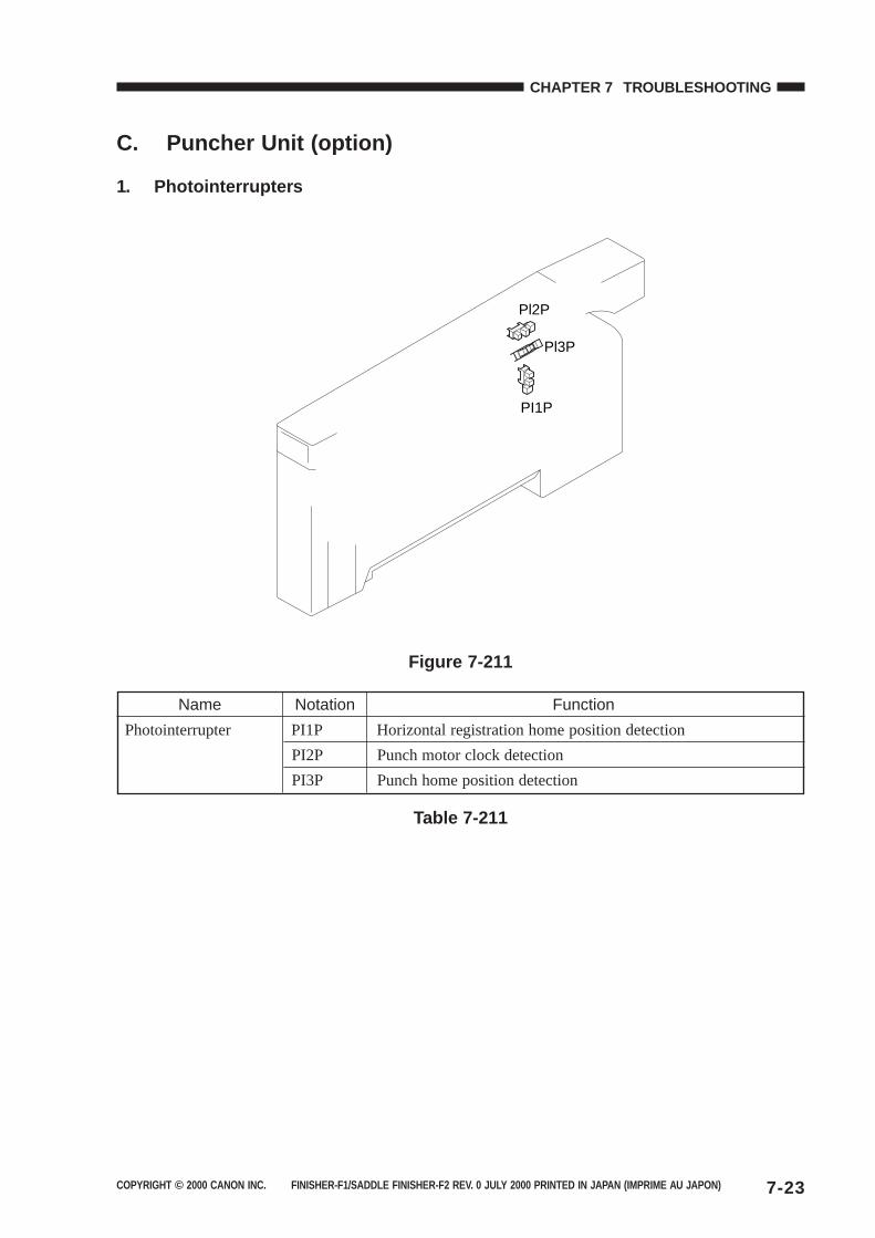
COPYRIGHT © 2000 CANON INC. FINISHER-F1/SADDLE FINISHER-F2 REV. 0 JULY 2000 PRINTED IN JAPAN (IMPRIME AU JAPON) 7-23
CHAPTER 7 TROUBLESHOOTING
C. Puncher Unit (option)
1. Photointerrupters
PI1P
Pl2P
Pl3P
Figure 7-211
Name Notation Function
Photointerrupter PI1P Horizontal registration home position detection
PI2P Punch motor clock detection
PI3P Punch home position detection
Table 7-211
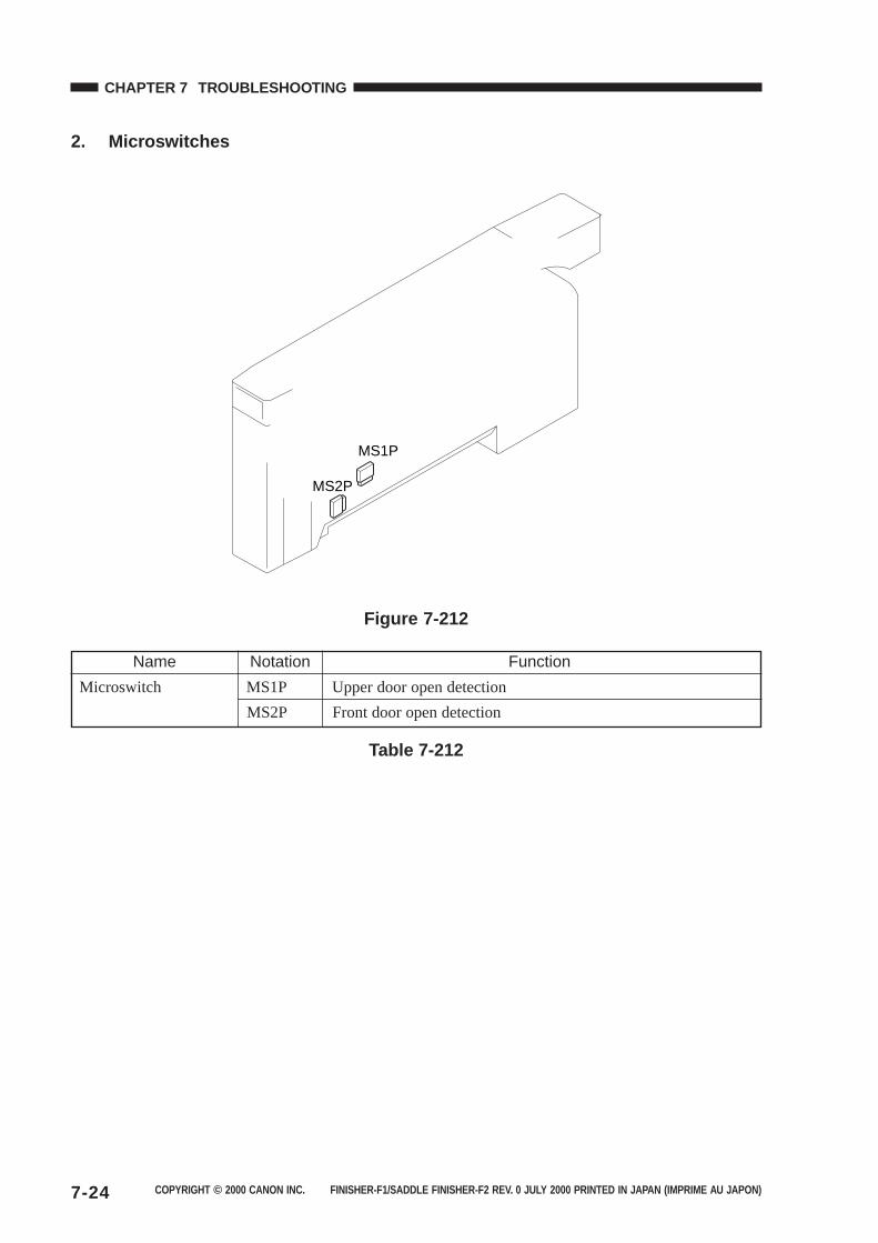
COPYRIGHT © 2000 CANON INC. FINISHER-F1/SADDLE FINISHER-F2 REV. 0 JULY 2000 PRINTED IN JAPAN (IMPRIME AU JAPON)7-24
CHAPTER 7 TROUBLESHOOTING
2. Microswitches
MS1P
MS2P
Figure 7-212
Name Notation Function
Microswitch MS1P Upper door open detection
MS2P Front door open detection
Table 7-212
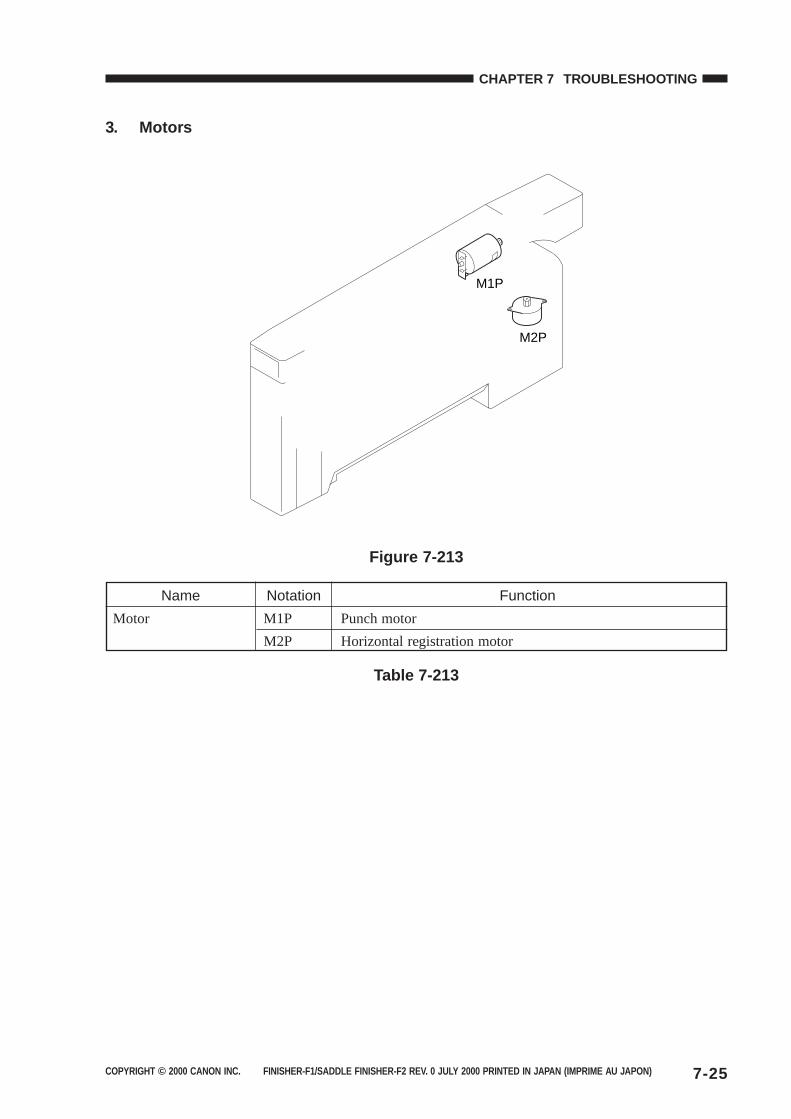
COPYRIGHT © 2000 CANON INC. FINISHER-F1/SADDLE FINISHER-F2 REV. 0 JULY 2000 PRINTED IN JAPAN (IMPRIME AU JAPON) 7-25
CHAPTER 7 TROUBLESHOOTING
3. Motors
M1P
M2P
Figure 7-213
Name Notation Function
Motor M1P Punch motor
M2P Horizontal registration motor
Table 7-213
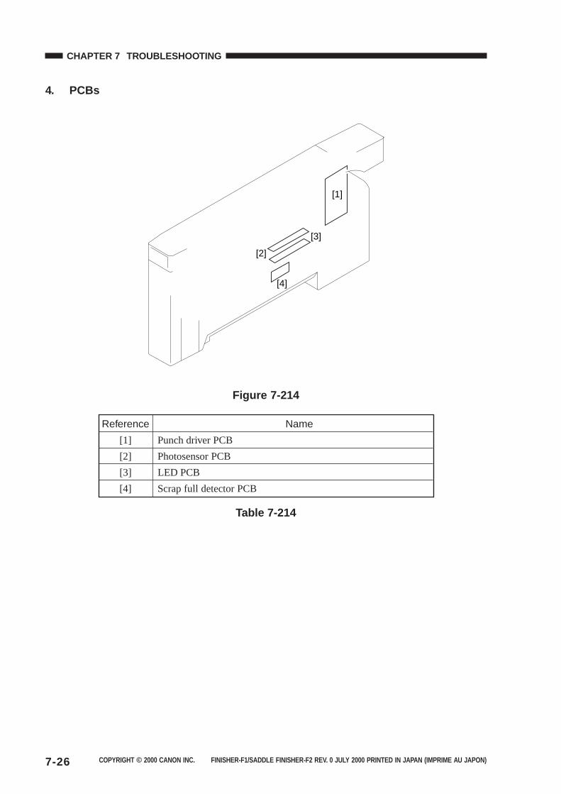
COPYRIGHT © 2000 CANON INC. FINISHER-F1/SADDLE FINISHER-F2 REV. 0 JULY 2000 PRINTED IN JAPAN (IMPRIME AU JAPON)7-26
CHAPTER 7 TROUBLESHOOTING
4. PCBs
[1]
[3]
[2]
[4]
Figure 7-214
Reference Name
[1] Punch driver PCB
[2] Photosensor PCB
[3] LED PCB
[4] Scrap full detector PCB
Table 7-214
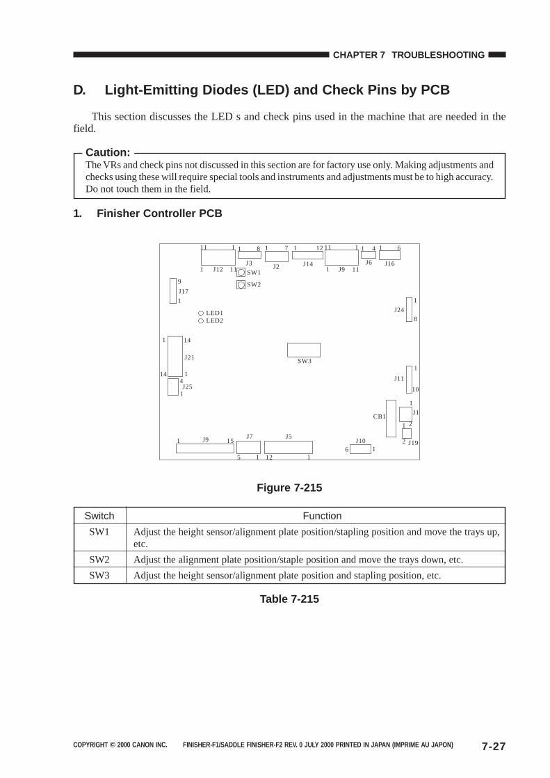
COPYRIGHT © 2000 CANON INC. FINISHER-F1/SADDLE FINISHER-F2 REV. 0 JULY 2000 PRINTED IN JAPAN (IMPRIME AU JAPON) 7-27
CHAPTER 7 TROUBLESHOOTING
D. Light-Emitting Diodes (LED) and Check Pins by PCB
This section discusses the LED s and check pins used in the machine that are needed in thefield.
Caution:The VRs and check pins not discussed in this section are for factory use only. Making adjustments andchecks using these will require special tools and instruments and adjustments must be to high accuracy.Do not touch them in the field.
1. Finisher Controller PCB
J12 J9
SW3
1
1
111
11J3
8 11
1J6
4 1 6
1
J24
8
J16
1 11
11J14
121
J2
7
1
1
J1
J19
2
216
J10J5J7
1 J9
J25
J21
1
J17
LED1
SW1
SW2
LED2
9
1
1
1
414
14
15
125 11
CB11
J11
10
Figure 7-215
Switch Function
SW1 Adjust the height sensor/alignment plate position/stapling position and move the trays up,etc.
SW2 Adjust the alignment plate position/staple position and move the trays down, etc.
SW3 Adjust the height sensor/alignment plate position and stapling position, etc.
Table 7-215
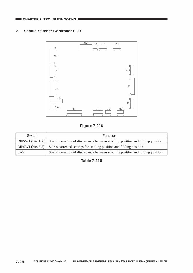
COPYRIGHT © 2000 CANON INC. FINISHER-F1/SADDLE FINISHER-F2 REV. 0 JULY 2000 PRINTED IN JAPAN (IMPRIME AU JAPON)7-28
CHAPTER 7 TROUBLESHOOTING
2. Saddle Stitcher Controller PCB
15
1
J11
10
1
10
1
114
J8
18
J15
14
J5
1
1
9
5
J12
J6
1
1 6
8
J10
J2
1 7
J13
1 3
J18SW1
1
15
J9
2
CB1
1J1
J7
J4
Figure 7-216
Switch Function
DIPSW1 (bits 1-2) Starts correction of discrepancy between stitching position and folding position.
DIPSW1 (bits 6-8) Stores corrected settings for stapling position and folding position.
SW2 Starts correction of discrepancy between stitching position and folding position.
Table 7-216
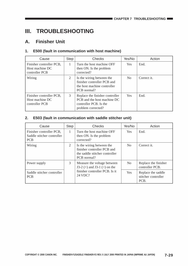
COPYRIGHT © 2000 CANON INC. FINISHER-F1/SADDLE FINISHER-F2 REV. 0 JULY 2000 PRINTED IN JAPAN (IMPRIME AU JAPON) 7-29
CHAPTER 7 TROUBLESHOOTING
III. TROUBLESHOOTING
A. Finisher Unit
1. E500 (fault in communication with host machine)
2. E503 (fault in communication with saddle stitcher unit)
Checks
Turn the host machine OFFthen ON. Is the problemcorrected?
Is the wiring between thefinisher controller PCB andthe host machine controllerPCB normal?
Replace the finisher controllerPCB and the host machine DCcontroller PCB. Is theproblem corrected?
Cause
Finisher controller PCB,Host machine DCcontroller PCB
Wiring
Finisher controller PCB,Host machine DCcontroller PCB
Step
1
2
3
Yes/No
Yes
No
Yes
Action
End.
Correct it.
End.
Checks
Turn the host machine OFFthen ON. Is the problemcorrected?
Is the wiring between thefinisher controller PCB andthe saddle stitcher controllerPCB normal?
Measure the voltage betweenJ3-2 (+) and J3-1 (−) on thefinisher controller PCB. Is it24 VDC?
Cause
Finisher controller PCB,Saddle stitcher controllerPCB
Wiring
Power supply
Saddle stitcher controllerPCB
Step
1
2
3
Yes/No
Yes
No
No
Yes
Action
End.
Correct it.
Replace the finishercontroller PCB.
Replace the saddlestitcher controllerPCB.
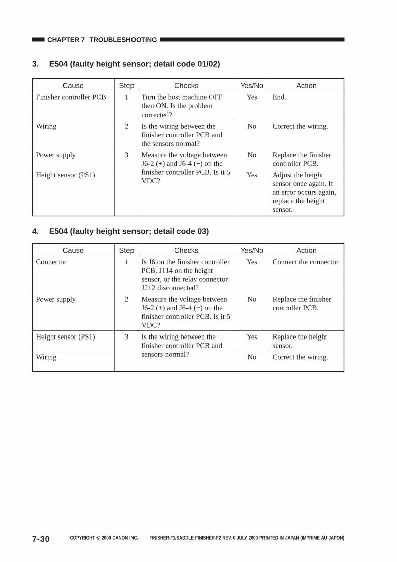
COPYRIGHT © 2000 CANON INC. FINISHER-F1/SADDLE FINISHER-F2 REV. 0 JULY 2000 PRINTED IN JAPAN (IMPRIME AU JAPON)7-30
CHAPTER 7 TROUBLESHOOTING
3. E504 (faulty height sensor; detail code 01/02)
4. E504 (faulty height sensor; detail code 03)
Checks
Is J6 on the finisher controllerPCB, J114 on the heightsensor, or the relay connectorJ212 disconnected?
Measure the voltage betweenJ6-2 (+) and J6-4 (−) on thefinisher controller PCB. Is it 5VDC?
Is the wiring between thefinisher controller PCB andsensors normal?
Cause
Connector
Power supply
Height sensor (PS1)
Wiring
Step
1
2
3
Yes/No
Yes
No
Yes
No
Action
Connect the connector.
Replace the finishercontroller PCB.
Replace the heightsensor.
Correct the wiring.
Checks
Turn the host machine OFFthen ON. Is the problemcorrected?
Is the wiring between thefinisher controller PCB andthe sensors normal?
Measure the voltage betweenJ6-2 (+) and J6-4 (−) on thefinisher controller PCB. Is it 5VDC?
Cause
Finisher controller PCB
Wiring
Power supply
Height sensor (PS1)
Step
1
2
3
Yes/No
Yes
No
No
Yes
Action
End.
Correct the wiring.
Replace the finishercontroller PCB.
Adjust the heightsensor once again. Ifan error occurs again,replace the heightsensor.
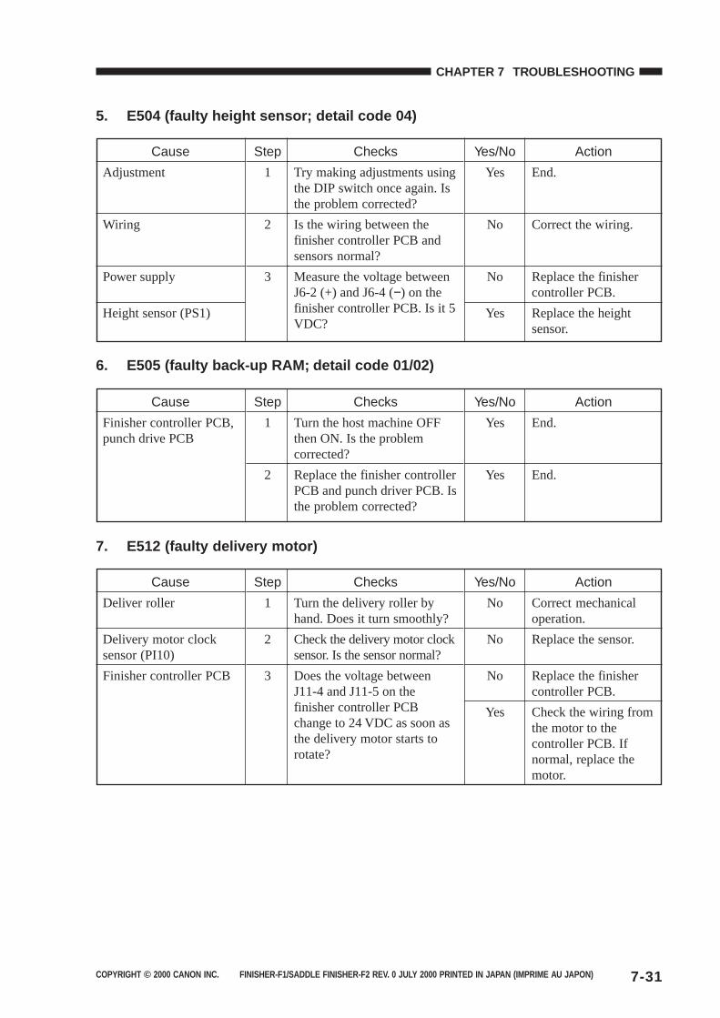
COPYRIGHT © 2000 CANON INC. FINISHER-F1/SADDLE FINISHER-F2 REV. 0 JULY 2000 PRINTED IN JAPAN (IMPRIME AU JAPON) 7-31
CHAPTER 7 TROUBLESHOOTING
5. E504 (faulty height sensor; detail code 04)
6. E505 (faulty back-up RAM; detail code 01/02)
7. E512 (faulty delivery motor)
Checks
Try making adjustments usingthe DIP switch once again. Isthe problem corrected?
Is the wiring between thefinisher controller PCB andsensors normal?
Measure the voltage betweenJ6-2 (+) and J6-4 (−) on thefinisher controller PCB. Is it 5VDC?
Cause
Adjustment
Wiring
Power supply
Height sensor (PS1)
Step
1
2
3
Yes/No
Yes
No
No
Yes
Action
End.
Correct the wiring.
Replace the finishercontroller PCB.
Replace the heightsensor.
Checks
Turn the delivery roller byhand. Does it turn smoothly?
Check the delivery motor clocksensor. Is the sensor normal?
Does the voltage betweenJ11-4 and J11-5 on thefinisher controller PCBchange to 24 VDC as soon asthe delivery motor starts torotate?
Cause
Deliver roller
Delivery motor clocksensor (PI10)
Finisher controller PCB
Step
1
2
3
Yes/No
No
No
No
Yes
Action
Correct mechanicaloperation.
Replace the sensor.
Replace the finishercontroller PCB.
Check the wiring fromthe motor to thecontroller PCB. Ifnormal, replace themotor.
Checks
Turn the host machine OFFthen ON. Is the problemcorrected?
Replace the finisher controllerPCB and punch driver PCB. Isthe problem corrected?
Cause
Finisher controller PCB,punch drive PCB
Step
1
2
Yes/No
Yes
Yes
Action
End.
End.
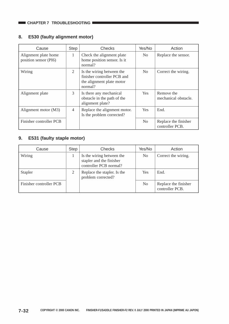
COPYRIGHT © 2000 CANON INC. FINISHER-F1/SADDLE FINISHER-F2 REV. 0 JULY 2000 PRINTED IN JAPAN (IMPRIME AU JAPON)7-32
CHAPTER 7 TROUBLESHOOTING
8. E530 (faulty alignment motor)
9. E531 (faulty staple motor)
Checks
Is the wiring between thestapler and the finishercontroller PCB normal?
Replace the stapler. Is theproblem corrected?
Cause
Wiring
Stapler
Finisher controller PCB
Step
1
2
Yes/No
No
Yes
No
Action
Correct the wiring.
End.
Replace the finishercontroller PCB.
Checks
Check the alignment platehome position sensor. Is itnormal?
Is the wiring between thefinisher controller PCB andthe alignment plate motornormal?
Is there any mechanicalobstacle in the path of thealignment plate?
Replace the alignment motor.Is the problem corrected?
Cause
Alignment plate homeposition sensor (PI6)
Wiring
Alignment plate
Alignment motor (M3)
Finisher controller PCB
Step
1
2
3
4
Yes/No
No
No
Yes
Yes
No
Action
Replace the sensor.
Correct the wiring.
Remove themechanical obstacle.
End.
Replace the finishercontroller PCB.
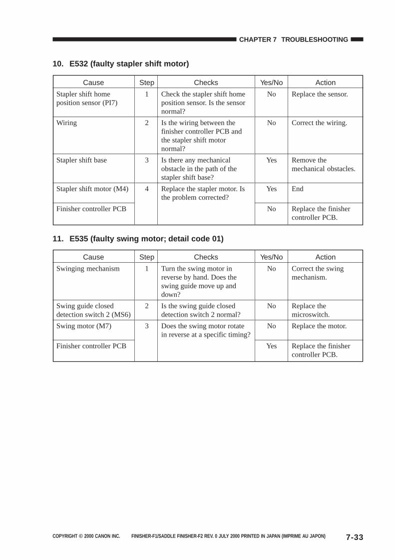
COPYRIGHT © 2000 CANON INC. FINISHER-F1/SADDLE FINISHER-F2 REV. 0 JULY 2000 PRINTED IN JAPAN (IMPRIME AU JAPON) 7-33
CHAPTER 7 TROUBLESHOOTING
10. E532 (faulty stapler shift motor)
11. E535 (faulty swing motor; detail code 01)
Checks
Check the stapler shift homeposition sensor. Is the sensornormal?
Is the wiring between thefinisher controller PCB andthe stapler shift motornormal?
Is there any mechanicalobstacle in the path of thestapler shift base?
Replace the stapler motor. Isthe problem corrected?
Cause
Stapler shift homeposition sensor (PI7)
Wiring
Stapler shift base
Stapler shift motor (M4)
Finisher controller PCB
Step
1
2
3
4
Yes/No
No
No
Yes
Yes
No
Action
Replace the sensor.
Correct the wiring.
Remove themechanical obstacles.
End
Replace the finishercontroller PCB.
Checks
Turn the swing motor inreverse by hand. Does theswing guide move up anddown?
Is the swing guide closeddetection switch 2 normal?
Does the swing motor rotatein reverse at a specific timing?
Cause
Swinging mechanism
Swing guide closeddetection switch 2 (MS6)
Swing motor (M7)
Finisher controller PCB
Step
1
2
3
Yes/No
No
No
No
Yes
Action
Correct the swingmechanism.
Replace themicroswitch.
Replace the motor.
Replace the finishercontroller PCB.
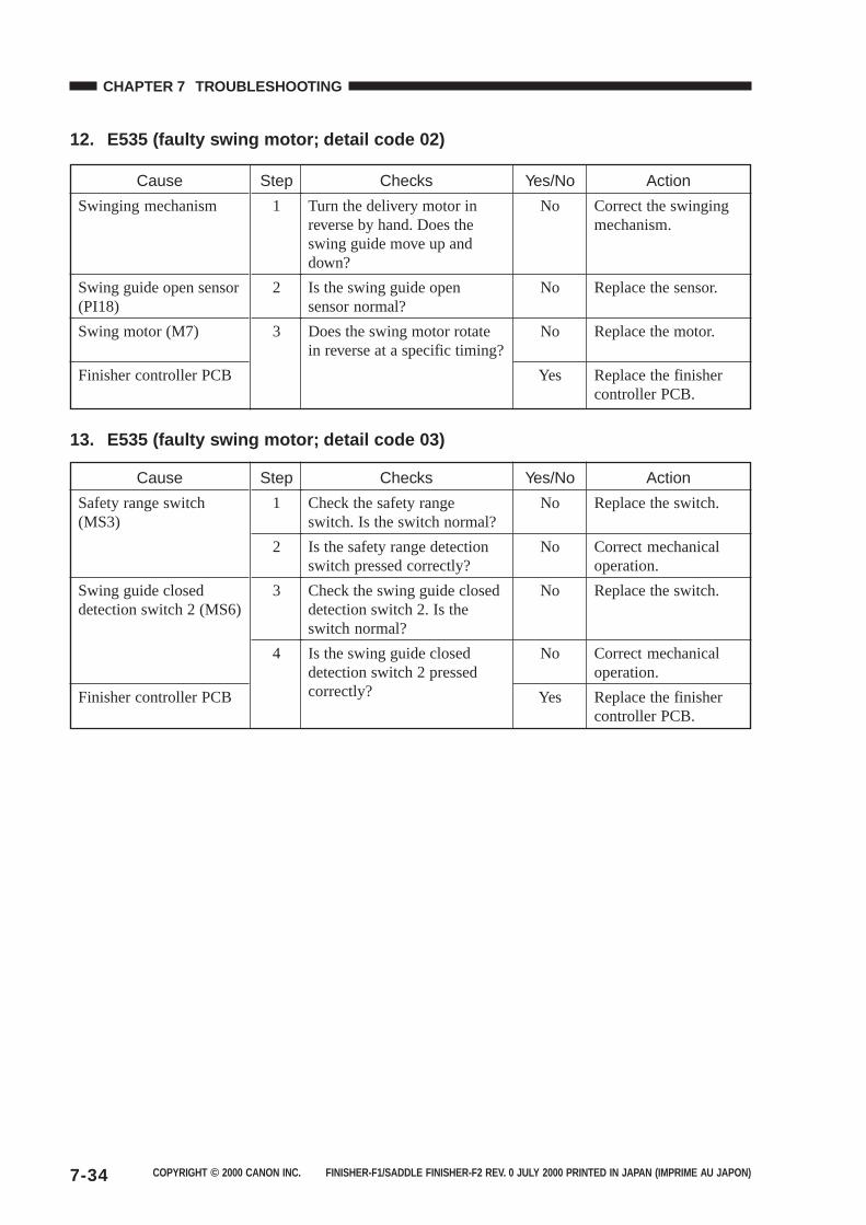
COPYRIGHT © 2000 CANON INC. FINISHER-F1/SADDLE FINISHER-F2 REV. 0 JULY 2000 PRINTED IN JAPAN (IMPRIME AU JAPON)7-34
CHAPTER 7 TROUBLESHOOTING
12. E535 (faulty swing motor; detail code 02)
13. E535 (faulty swing motor; detail code 03)
Checks
Turn the delivery motor inreverse by hand. Does theswing guide move up anddown?
Is the swing guide opensensor normal?
Does the swing motor rotatein reverse at a specific timing?
Cause
Swinging mechanism
Swing guide open sensor(PI18)
Swing motor (M7)
Finisher controller PCB
Step
1
2
3
Yes/No
No
No
No
Yes
Action
Correct the swingingmechanism.
Replace the sensor.
Replace the motor.
Replace the finishercontroller PCB.
Checks
Check the safety rangeswitch. Is the switch normal?
Is the safety range detectionswitch pressed correctly?
Check the swing guide closeddetection switch 2. Is theswitch normal?
Is the swing guide closeddetection switch 2 pressedcorrectly?
Cause
Safety range switch(MS3)
Swing guide closeddetection switch 2 (MS6)
Finisher controller PCB
Step
1
2
3
4
Yes/No
No
No
No
No
Yes
Action
Replace the switch.
Correct mechanicaloperation.
Replace the switch.
Correct mechanicaloperation.
Replace the finishercontroller PCB.
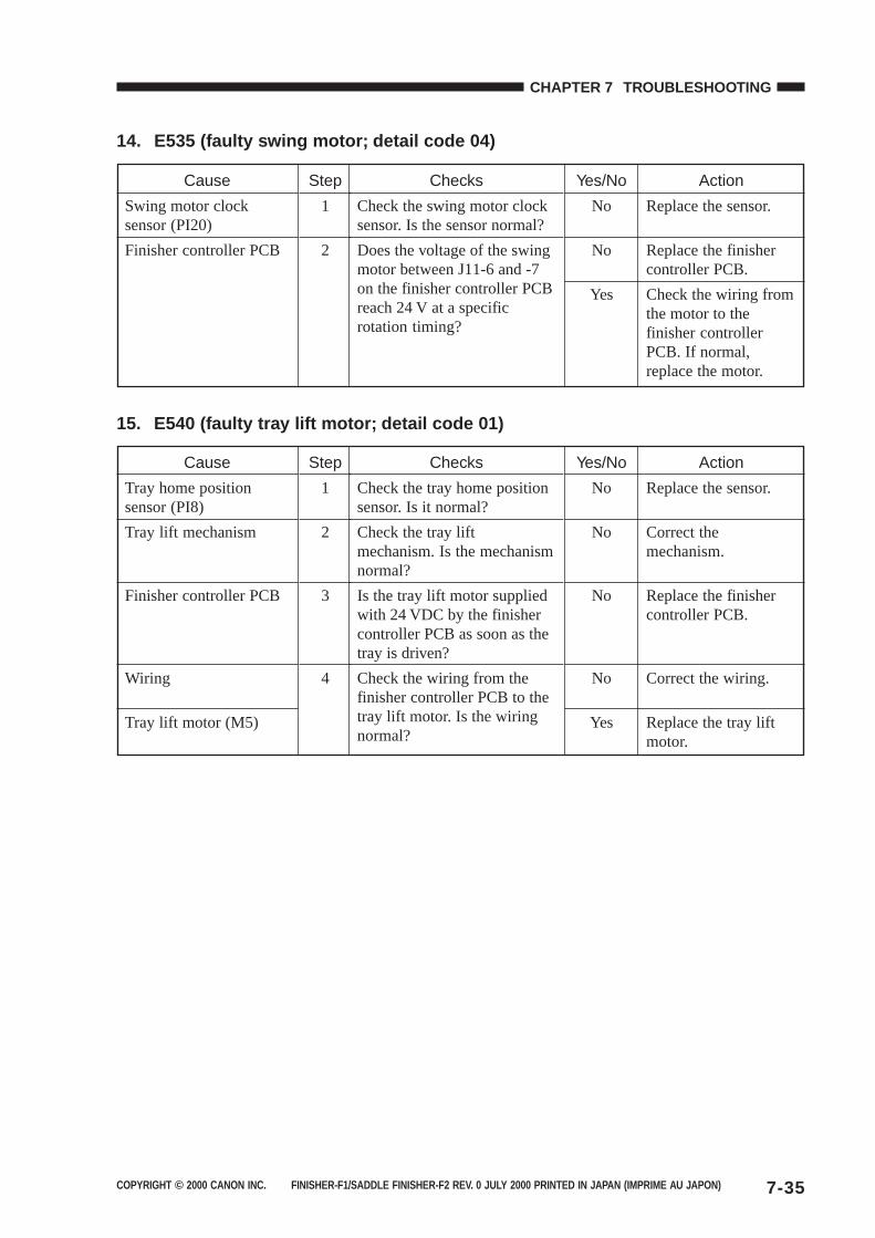
COPYRIGHT © 2000 CANON INC. FINISHER-F1/SADDLE FINISHER-F2 REV. 0 JULY 2000 PRINTED IN JAPAN (IMPRIME AU JAPON) 7-35
CHAPTER 7 TROUBLESHOOTING
14. E535 (faulty swing motor; detail code 04)
15. E540 (faulty tray lift motor; detail code 01)
Checks
Check the swing motor clocksensor. Is the sensor normal?
Does the voltage of the swingmotor between J11-6 and -7on the finisher controller PCBreach 24 V at a specificrotation timing?
Cause
Swing motor clocksensor (PI20)
Finisher controller PCB
Step
1
2
Yes/No
No
No
Yes
Action
Replace the sensor.
Replace the finishercontroller PCB.
Check the wiring fromthe motor to thefinisher controllerPCB. If normal,replace the motor.
Checks
Check the tray home positionsensor. Is it normal?
Check the tray liftmechanism. Is the mechanismnormal?
Is the tray lift motor suppliedwith 24 VDC by the finishercontroller PCB as soon as thetray is driven?
Check the wiring from thefinisher controller PCB to thetray lift motor. Is the wiringnormal?
Cause
Tray home positionsensor (PI8)
Tray lift mechanism
Finisher controller PCB
Wiring
Tray lift motor (M5)
Step
1
2
3
4
Yes/No
No
No
No
No
Yes
Action
Replace the sensor.
Correct themechanism.
Replace the finishercontroller PCB.
Correct the wiring.
Replace the tray liftmotor.
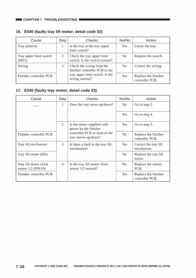
COPYRIGHT © 2000 CANON INC. FINISHER-F1/SADDLE FINISHER-F2 REV. 0 JULY 2000 PRINTED IN JAPAN (IMPRIME AU JAPON)7-36
CHAPTER 7 TROUBLESHOOTING
16. E540 (faulty tray lift motor; detail code 02)
17. E540 (faulty tray motor; detail code 03)
Checks
Is the tray at the tray upperlimit switch?
Check the tray upper limitswitch. Is the switch normal?
Check the wiring from thefinisher controller PCB to thetray upper limit switch. Is thewiring normal?
Cause
Tray position
Tray upper limit switch(MS5)
Wiring
Finisher controller PCB
Step
1
2
3
Yes/No
Yes
No
No
Yes
Action
Lower the tray.
Replace the switch.
Correct the wiring.
Replace the finishercontroller PCB.
Checks
Does the tray move up/down?
Is the motor supplied withpower by the finishercontroller PCB as soon as thetray moves up/down?
Is there a fault in the tray liftmechanism?
Is the tray lift motor clocksensor 1/2 normal?
Cause
___
Finisher controller PCB
Tray lift mechanism
Tray lift motor (M5)
Tray lift motor clocksensor 1/2 (PI9/19)
Finisher controller PCB
Step
1
2
3
4
Yes/No
No
Yes
Yes
No
Yes
No
No
Yes
Action
Go to step 2.
Go to step 4.
Go to step 3.
Replace the finishercontroller PCB.
Correct the tray liftmechanism.
Replace the tray liftmotor.
Replace the sensorPCB.
Replace the finishercontroller PCB.
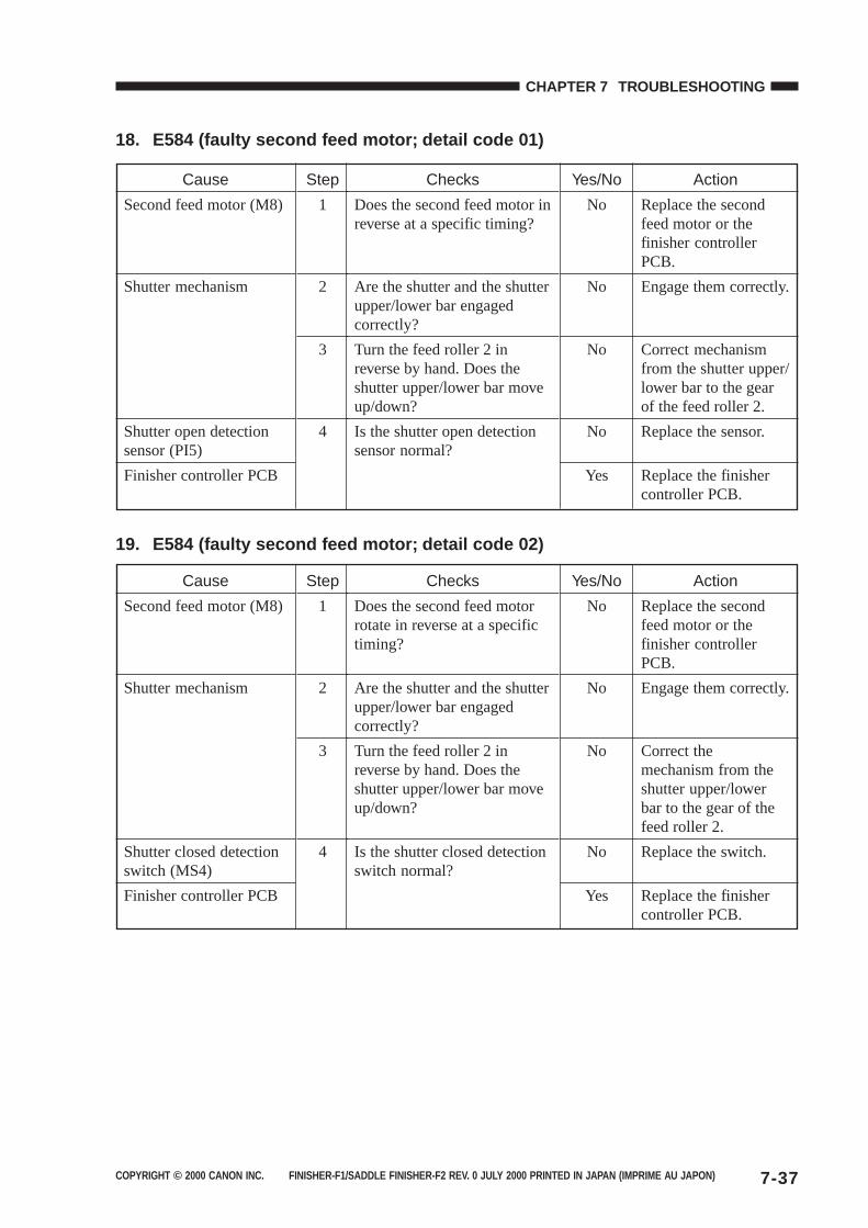
COPYRIGHT © 2000 CANON INC. FINISHER-F1/SADDLE FINISHER-F2 REV. 0 JULY 2000 PRINTED IN JAPAN (IMPRIME AU JAPON) 7-37
CHAPTER 7 TROUBLESHOOTING
18. E584 (faulty second feed motor; detail code 01)
19. E584 (faulty second feed motor; detail code 02)
Checks
Does the second feed motor inreverse at a specific timing?
Are the shutter and the shutterupper/lower bar engagedcorrectly?
Turn the feed roller 2 inreverse by hand. Does theshutter upper/lower bar moveup/down?
Is the shutter open detectionsensor normal?
Cause
Second feed motor (M8)
Shutter mechanism
Shutter open detectionsensor (PI5)
Finisher controller PCB
Step
1
2
3
4
Yes/No
No
No
No
No
Yes
Action
Replace the secondfeed motor or thefinisher controllerPCB.
Engage them correctly.
Correct mechanismfrom the shutter upper/lower bar to the gearof the feed roller 2.
Replace the sensor.
Replace the finishercontroller PCB.
Checks
Does the second feed motorrotate in reverse at a specifictiming?
Are the shutter and the shutterupper/lower bar engagedcorrectly?
Turn the feed roller 2 inreverse by hand. Does theshutter upper/lower bar moveup/down?
Is the shutter closed detectionswitch normal?
Cause
Second feed motor (M8)
Shutter mechanism
Shutter closed detectionswitch (MS4)
Finisher controller PCB
Step
1
2
3
4
Yes/No
No
No
No
No
Yes
Action
Replace the secondfeed motor or thefinisher controllerPCB.
Engage them correctly.
Correct themechanism from theshutter upper/lowerbar to the gear of thefeed roller 2.
Replace the switch.
Replace the finishercontroller PCB.
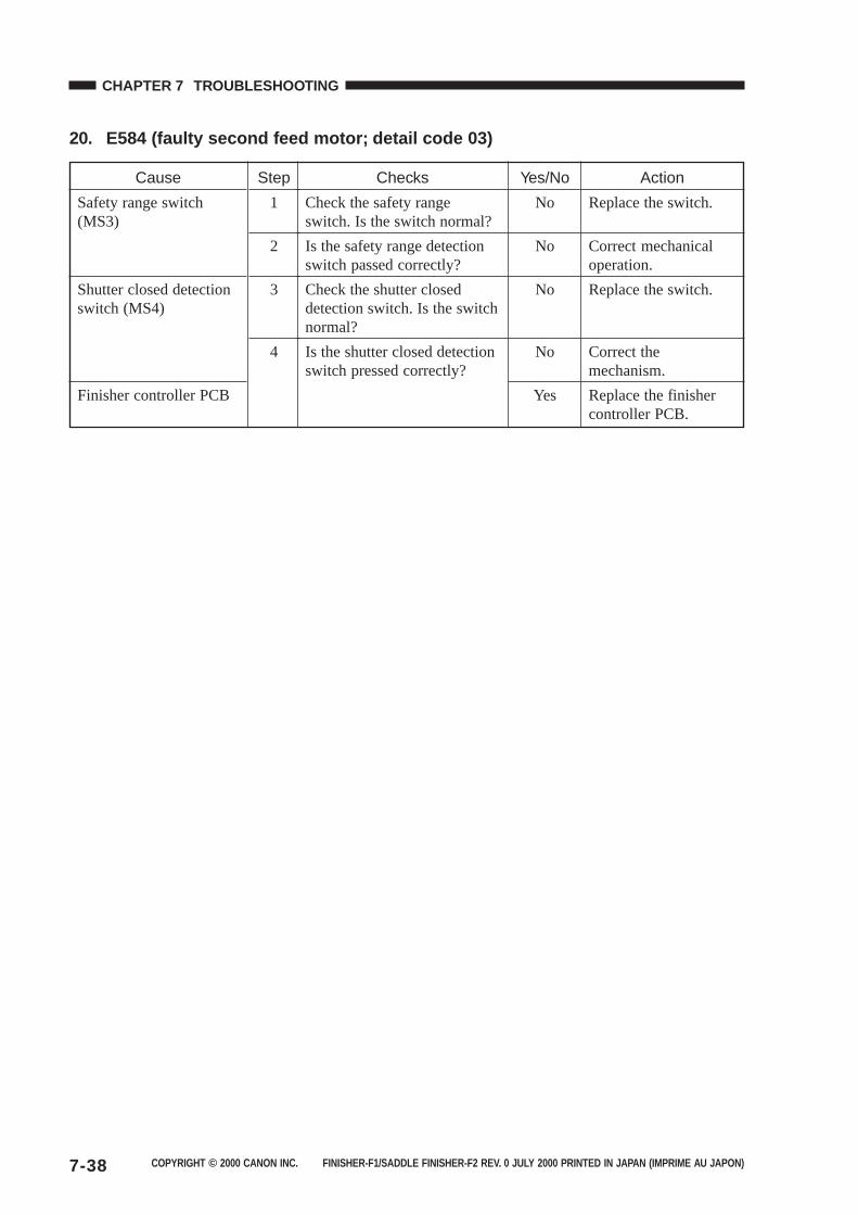
COPYRIGHT © 2000 CANON INC. FINISHER-F1/SADDLE FINISHER-F2 REV. 0 JULY 2000 PRINTED IN JAPAN (IMPRIME AU JAPON)7-38
CHAPTER 7 TROUBLESHOOTING
20. E584 (faulty second feed motor; detail code 03)
Checks
Check the safety rangeswitch. Is the switch normal?
Is the safety range detectionswitch passed correctly?
Check the shutter closeddetection switch. Is the switchnormal?
Is the shutter closed detectionswitch pressed correctly?
Cause
Safety range switch(MS3)
Shutter closed detectionswitch (MS4)
Finisher controller PCB
Step
1
2
3
4
Yes/No
No
No
No
No
Yes
Action
Replace the switch.
Correct mechanicaloperation.
Replace the switch.
Correct themechanism.
Replace the finishercontroller PCB.

COPYRIGHT © 2000 CANON INC. FINISHER-F1/SADDLE FINISHER-F2 REV. 0 JULY 2000 PRINTED IN JAPAN (IMPRIME AU JAPON) 7-39
CHAPTER 7 TROUBLESHOOTING
B. Saddle Stitcher Unit
1. E5F0 (faulty paper positioning plate; detail code 01/02)
2. E5F1 (faulty paper folding motor; detail code 01/02)
Checks
Check the paper positioningplate home position sensor. Isthe sensor normal?
Do the paper positioningplates operate at a specifictiming?
Replace the paper positioningplate motor. Is the problemcorrected?
Cause
Paper positioning platehome position sensor(PI7S)
Saddle stitcher controllerPCB
Paper positioning platemotor (M4S)
Saddle stitcher controllerPCB
Step
1
2
3
Yes/No
No
Yes
No
Yes
No
Action
Replace the sensor.
Replace the saddlestitcher controllerPCB.
Check the positioningplate drivemechanism. If a faultis found, correct it.Otherwise, go to step3.
End.
Replace the saddlestitcher controllerPCB.
Checks
Check the paper foldingmotor clock sensor. Is thesensor normal?
Check the paper folding homeposition sensor. Is the sensornormal?
Does the paper folding motoroperate at a specific timing?
Replace the paper foldingmotor. Is the problemcorrected?
Cause
Paper folding motorclock sensor (PI4S)
Paper folding homeposition sensor (PI21S)
Saddle stitcher controllerPCB
Paper folding motor(M2S)
Saddle stitcher controllerPCB
Step
1
2
3
4
Yes/No
No
No
Yes
No
Yes
No
Action
Replace the sensor.
Replace the sensor.
Replace the saddlestitcher controllerPCB.
Check the paperfolding roller drivemechanism. If a faultis found, correct it.Otherwise, go to step4.
End.
Replace the saddlestitcher controllerPCB.

COPYRIGHT © 2000 CANON INC. FINISHER-F1/SADDLE FINISHER-F2 REV. 0 JULY 2000 PRINTED IN JAPAN (IMPRIME AU JAPON)7-40
CHAPTER 7 TROUBLESHOOTING
3. E5F2 (faulty guide motor; detail code 01/02)
4. E5F3 (faulty alignment motor; detail code 01/02)
Checks
Check the guide homeposition sensor. Is the sensornormal?
Does the guide motor operateat a specific timing?
Replace the guide motor. Isthe problem corrected?
Cause
Guide home positionsensor (PI13S)
Saddle stitcher controllerPCB
Guide motor (M3S)
Saddle stitcher controllerPCB
Step
1
2
3
Yes/No
No
Yes
No
Yes
No
Action
Replace the sensor.
Replace the saddlestitcher controllerPCB.
Check the guide platedrive mechanism. If afault is found, correctit. Otherwise, go tostep 3.
End.
Replace the saddlestitcher controllerPCB.
Checks
Check the alignment platehome position sensor. Is thesensor normal?
Does the alignment motoroperate at a specific timing?
Replace the alignment motor.Is the problem corrected?
Cause
Alignment plate homeposition sensor (PI5S)
Saddle stitcher controllerPCB
Alignment motor (M5S)
Saddle stitcher controllerPCB
Step
1
2
3
Yes/No
No
Yes
No
Yes
No
Action
Replace the sensor.
Replace the saddlestitcher controllerPCB.
Check the alignmentplate drivemechanism. If a faultis found, correct it.Otherwise, go to step3.
End.
Replace the saddlestitcher controllerPCB.
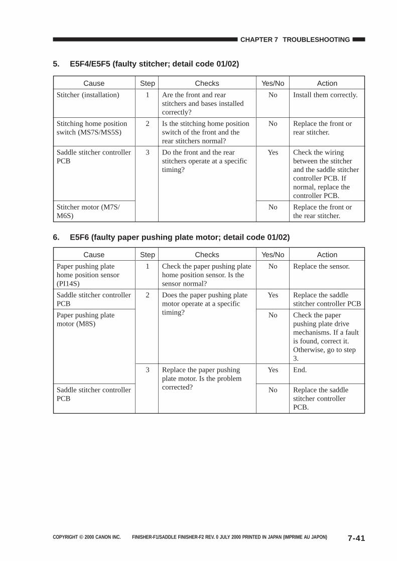
COPYRIGHT © 2000 CANON INC. FINISHER-F1/SADDLE FINISHER-F2 REV. 0 JULY 2000 PRINTED IN JAPAN (IMPRIME AU JAPON) 7-41
CHAPTER 7 TROUBLESHOOTING
5. E5F4/E5F5 (faulty stitcher; detail code 01/02)
6. E5F6 (faulty paper pushing plate motor; detail code 01/02)
Checks
Are the front and rearstitchers and bases installedcorrectly?
Is the stitching home positionswitch of the front and therear stitchers normal?
Do the front and the rearstitchers operate at a specifictiming?
Cause
Stitcher (installation)
Stitching home positionswitch (MS7S/MS5S)
Saddle stitcher controllerPCB
Stitcher motor (M7S/M6S)
Step
1
2
3
Yes/No
No
No
Yes
No
Action
Install them correctly.
Replace the front orrear stitcher.
Check the wiringbetween the stitcherand the saddle stitchercontroller PCB. Ifnormal, replace thecontroller PCB.
Replace the front orthe rear stitcher.
Checks
Check the paper pushing platehome position sensor. Is thesensor normal?
Does the paper pushing platemotor operate at a specifictiming?
Replace the paper pushingplate motor. Is the problemcorrected?
Cause
Paper pushing platehome position sensor(PI14S)
Saddle stitcher controllerPCB
Paper pushing platemotor (M8S)
Saddle stitcher controllerPCB
Step
1
2
3
Yes/No
No
Yes
No
Yes
No
Action
Replace the sensor.
Replace the saddlestitcher controller PCB
Check the paperpushing plate drivemechanisms. If a faultis found, correct it.Otherwise, go to step3.
End.
Replace the saddlestitcher controllerPCB.
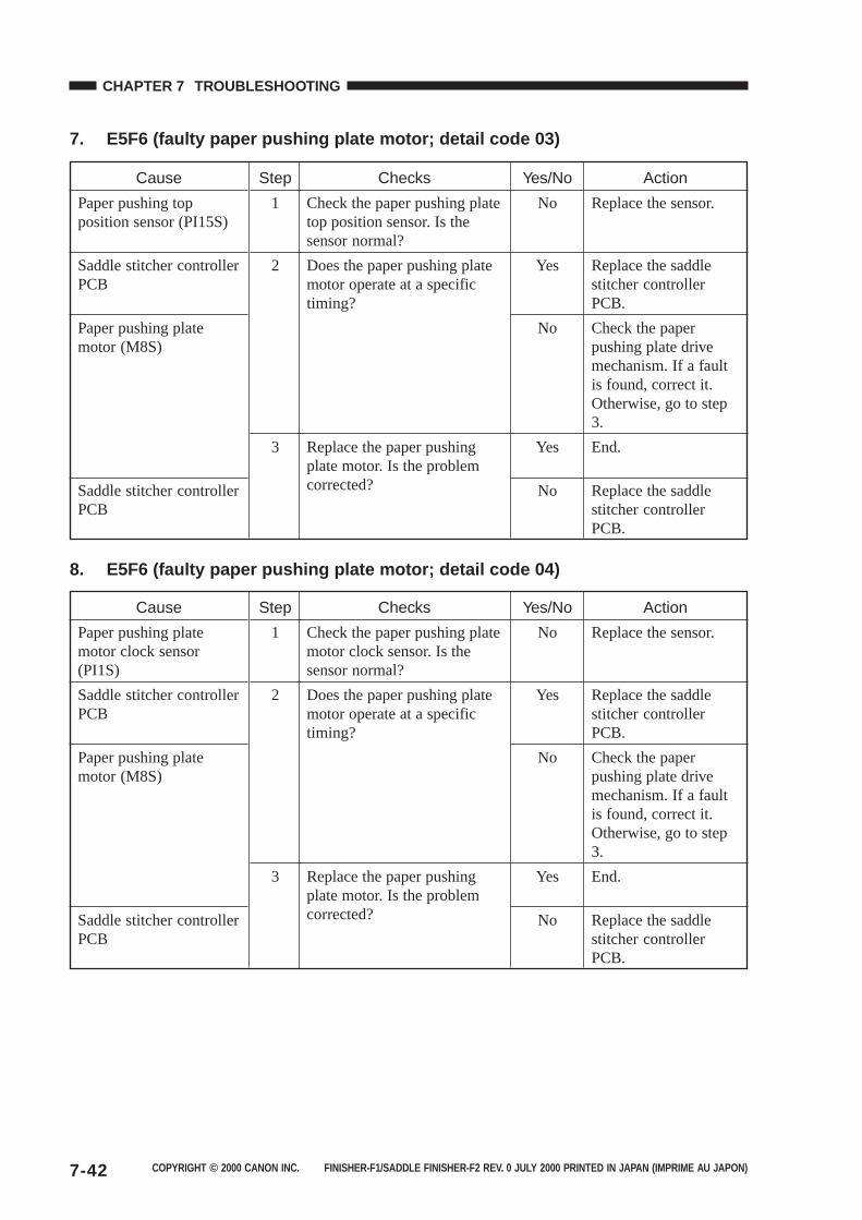
COPYRIGHT © 2000 CANON INC. FINISHER-F1/SADDLE FINISHER-F2 REV. 0 JULY 2000 PRINTED IN JAPAN (IMPRIME AU JAPON)7-42
CHAPTER 7 TROUBLESHOOTING
7. E5F6 (faulty paper pushing plate motor; detail code 03)
8. E5F6 (faulty paper pushing plate motor; detail code 04)
Checks
Check the paper pushing platetop position sensor. Is thesensor normal?
Does the paper pushing platemotor operate at a specifictiming?
Replace the paper pushingplate motor. Is the problemcorrected?
Cause
Paper pushing topposition sensor (PI15S)
Saddle stitcher controllerPCB
Paper pushing platemotor (M8S)
Saddle stitcher controllerPCB
Step
1
2
3
Yes/No
No
Yes
No
Yes
No
Action
Replace the sensor.
Replace the saddlestitcher controllerPCB.
Check the paperpushing plate drivemechanism. If a faultis found, correct it.Otherwise, go to step3.
End.
Replace the saddlestitcher controllerPCB.
Checks
Check the paper pushing platemotor clock sensor. Is thesensor normal?
Does the paper pushing platemotor operate at a specifictiming?
Replace the paper pushingplate motor. Is the problemcorrected?
Cause
Paper pushing platemotor clock sensor(PI1S)
Saddle stitcher controllerPCB
Paper pushing platemotor (M8S)
Saddle stitcher controllerPCB
Step
1
2
3
Yes/No
No
Yes
No
Yes
No
Action
Replace the sensor.
Replace the saddlestitcher controllerPCB.
Check the paperpushing plate drivemechanism. If a faultis found, correct it.Otherwise, go to step3.
End.
Replace the saddlestitcher controllerPCB.
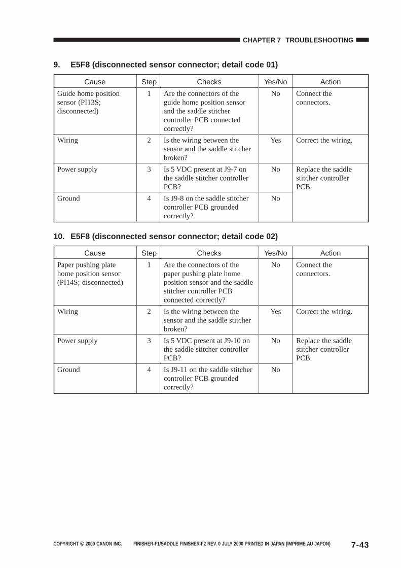
COPYRIGHT © 2000 CANON INC. FINISHER-F1/SADDLE FINISHER-F2 REV. 0 JULY 2000 PRINTED IN JAPAN (IMPRIME AU JAPON) 7-43
CHAPTER 7 TROUBLESHOOTING
9. E5F8 (disconnected sensor connector; detail code 01)
10. E5F8 (disconnected sensor connector; detail code 02)
Checks
Are the connectors of theguide home position sensorand the saddle stitchercontroller PCB connectedcorrectly?
Is the wiring between thesensor and the saddle stitcherbroken?
Is 5 VDC present at J9-7 onthe saddle stitcher controllerPCB?
Is J9-8 on the saddle stitchercontroller PCB groundedcorrectly?
Cause
Guide home positionsensor (PI13S;disconnected)
Wiring
Power supply
Ground
Step
1
2
3
4
Yes/No
No
Yes
No
No
Action
Connect theconnectors.
Correct the wiring.
Replace the saddlestitcher controllerPCB.
Checks
Are the connectors of thepaper pushing plate homeposition sensor and the saddlestitcher controller PCBconnected correctly?
Is the wiring between thesensor and the saddle stitcherbroken?
Is 5 VDC present at J9-10 onthe saddle stitcher controllerPCB?
Is J9-11 on the saddle stitchercontroller PCB groundedcorrectly?
Cause
Paper pushing platehome position sensor(PI14S; disconnected)
Wiring
Power supply
Ground
Step
1
2
3
4
Yes/No
No
Yes
No
No
Action
Connect theconnectors.
Correct the wiring.
Replace the saddlestitcher controllerPCB.
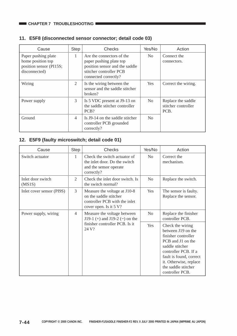
COPYRIGHT © 2000 CANON INC. FINISHER-F1/SADDLE FINISHER-F2 REV. 0 JULY 2000 PRINTED IN JAPAN (IMPRIME AU JAPON)7-44
CHAPTER 7 TROUBLESHOOTING
11. E5F8 (disconnected sensor connector; detail code 03)
12. E5F9 (faulty microswitch; detail code 01)
Checks
Are the connectors of thepaper pushing plate topposition sensor and the saddlestitcher controller PCBconnected correctly?
Is the wiring between thesensor and the saddle stitcherbroken?
Is 5 VDC present at J9-13 onthe saddle stitcher controllerPCB?
Is J9-14 on the saddle stitchercontroller PCB groundedcorrectly?
Cause
Paper pushing platehome position topposition sensor (PI15S;disconnected)
Wiring
Power supply
Ground
Step
1
2
3
4
Yes/No
No
Yes
No
No
Action
Connect theconnectors.
Correct the wiring.
Replace the saddlestitcher controllerPCB.
Checks
Check the switch actuator ofthe inlet door. Do the switchand the sensor operatecorrectly?
Check the inlet door switch. Isthe switch normal?
Measure the voltage at J10-8on the saddle stitchercontroller PCB with the inletcover open. Is it 5 V?
Measure the voltage betweenJ19-1 (+) and J19-2 (−) on thefinisher controller PCB. Is it24 V?
Cause
Switch actuator
Inlet door switch(MS1S)
Inlet cover sensor (PI9S)
Power supply, wiring
Step
1
2
3
4
Yes/No
No
No
Yes
No
Yes
Action
Correct themechanism.
Replace the switch.
The sensor is faulty.Replace the sensor.
Replace the finishercontroller PCB.
Check the wiringbetween J19 on thefinisher controllerPCB and J1 on thesaddle stitchercontroller PCB. If afault is found, correctit. Otherwise, replacethe saddle stitchercontroller PCB.
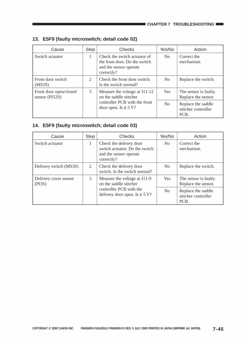
COPYRIGHT © 2000 CANON INC. FINISHER-F1/SADDLE FINISHER-F2 REV. 0 JULY 2000 PRINTED IN JAPAN (IMPRIME AU JAPON) 7-45
CHAPTER 7 TROUBLESHOOTING
13. E5F9 (faulty microswitch; detail code 02)
14. E5F9 (faulty microswitch; detail code 03)
Checks
Check the switch actuator ofthe front door. Do the switchand the sensor operatecorrectly?
Check the front door switch.Is the switch normal?
Measure the voltage at J11-12on the saddle stitchercontroller PCB with the frontdoor open. Is it 5 V?
Cause
Switch actuator
Front door switch(MS2S)
Front door open/closedsensor (PI12S)
Step
1
2
3
Yes/No
No
No
Yes
No
Action
Correct themechanism.
Replace the switch.
The sensor is faulty.Replace the sensor.
Replace the saddlestitcher controllerPCB.
Checks
Check the delivery doorswitch actuator. Do the switchand the sensor operatecorrectly?
Check the delivery doorswitch. Is the switch normal?
Measure the voltage at J11-9on the saddle stitchercontroller PCB with thedelivery door open. Is it 5 V?
Cause
Switch actuator
Delivery switch (MS3S)
Delivery cover sensor(PI3S)
Step
1
2
3
Yes/No
No
No
Yes
No
Action
Correct themechanism.
Replace the switch.
The sensor is faulty.Replace the sensor.
Replace the saddlestitcher controllerPCB.
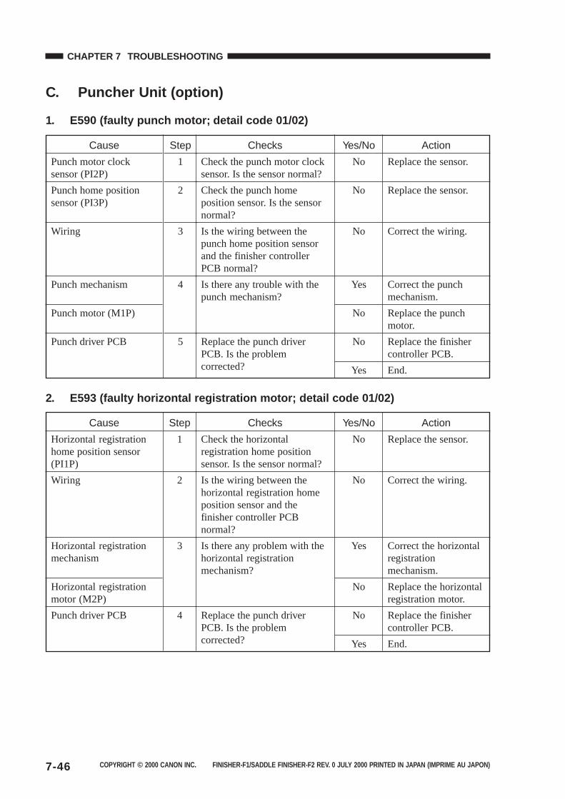
COPYRIGHT © 2000 CANON INC. FINISHER-F1/SADDLE FINISHER-F2 REV. 0 JULY 2000 PRINTED IN JAPAN (IMPRIME AU JAPON)7-46
CHAPTER 7 TROUBLESHOOTING
C. Puncher Unit (option)
1. E590 (faulty punch motor; detail code 01/02)
2. E593 (faulty horizontal registration motor; detail code 01/02)
Checks
Check the horizontalregistration home positionsensor. Is the sensor normal?
Is the wiring between thehorizontal registration homeposition sensor and thefinisher controller PCBnormal?
Is there any problem with thehorizontal registrationmechanism?
Replace the punch driverPCB. Is the problemcorrected?
Cause
Horizontal registrationhome position sensor(PI1P)
Wiring
Horizontal registrationmechanism
Horizontal registrationmotor (M2P)
Punch driver PCB
Step
1
2
3
4
Yes/No
No
No
Yes
No
No
Yes
Action
Replace the sensor.
Correct the wiring.
Correct the horizontalregistrationmechanism.
Replace the horizontalregistration motor.
Replace the finishercontroller PCB.
End.
Checks
Check the punch motor clocksensor. Is the sensor normal?
Check the punch homeposition sensor. Is the sensornormal?
Is the wiring between thepunch home position sensorand the finisher controllerPCB normal?
Is there any trouble with thepunch mechanism?
Replace the punch driverPCB. Is the problemcorrected?
Cause
Punch motor clocksensor (PI2P)
Punch home positionsensor (PI3P)
Wiring
Punch mechanism
Punch motor (M1P)
Punch driver PCB
Step
1
2
3
4
5
Yes/No
No
No
No
Yes
No
No
Yes
Action
Replace the sensor.
Replace the sensor.
Correct the wiring.
Correct the punchmechanism.
Replace the punchmotor.
Replace the finishercontroller PCB.
End.
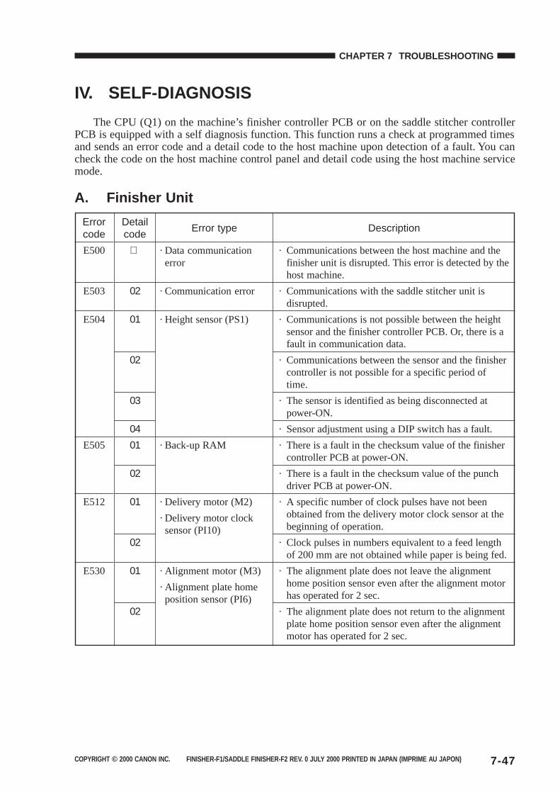
COPYRIGHT © 2000 CANON INC. FINISHER-F1/SADDLE FINISHER-F2 REV. 0 JULY 2000 PRINTED IN JAPAN (IMPRIME AU JAPON) 7-47
CHAPTER 7 TROUBLESHOOTING
IV. SELF-DIAGNOSIS
The CPU (Q1) on the machine’s finisher controller PCB or on the saddle stitcher controllerPCB is equipped with a self diagnosis function. This function runs a check at programmed timesand sends an error code and a detail code to the host machine upon detection of a fault. You cancheck the code on the host machine control panel and detail code using the host machine servicemode.
A. Finisher Unit
Errorcode
E500
E503
E504
E505
E512
E530
Detailcode
02
01
02
03
0401
02
01
02
01
02
Error type
· Data communicationerror
· Communication error
· Height sensor (PS1)
· Back-up RAM
· Delivery motor (M2)
· Delivery motor clocksensor (PI10)
· Alignment motor (M3)
· Alignment plate homeposition sensor (PI6)
Description
· Communications between the host machine and thefinisher unit is disrupted. This error is detected by thehost machine.
· Communications with the saddle stitcher unit isdisrupted.
· Communications is not possible between the heightsensor and the finisher controller PCB. Or, there is afault in communication data.
· Communications between the sensor and the finishercontroller is not possible for a specific period oftime.
· The sensor is identified as being disconnected atpower-ON.
· Sensor adjustment using a DIP switch has a fault.
· There is a fault in the checksum value of the finishercontroller PCB at power-ON.
· There is a fault in the checksum value of the punchdriver PCB at power-ON.
· A specific number of clock pulses have not beenobtained from the delivery motor clock sensor at thebeginning of operation.
· Clock pulses in numbers equivalent to a feed lengthof 200 mm are not obtained while paper is being fed.
· The alignment plate does not leave the alignmenthome position sensor even after the alignment motorhas operated for 2 sec.
· The alignment plate does not return to the alignmentplate home position sensor even after the alignmentmotor has operated for 2 sec.
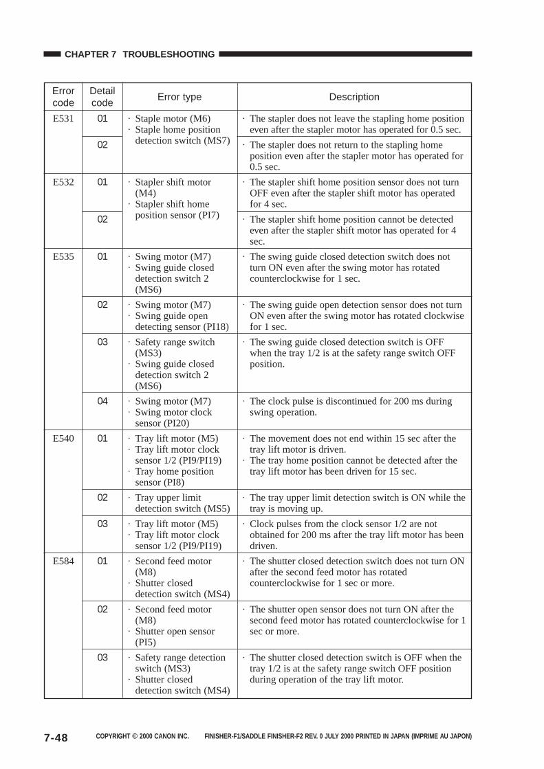
COPYRIGHT © 2000 CANON INC. FINISHER-F1/SADDLE FINISHER-F2 REV. 0 JULY 2000 PRINTED IN JAPAN (IMPRIME AU JAPON)7-48
CHAPTER 7 TROUBLESHOOTING
Errorcode
E531
E532
E535
E540
E584
Detailcode
01
02
01
02
01
02
03
04
01
02
03
01
02
03
Error type
· Staple motor (M6)· Staple home position
detection switch (MS7)
· Stapler shift motor(M4)
· Stapler shift homeposition sensor (PI7)
· Swing motor (M7)· Swing guide closed
detection switch 2(MS6)
· Swing motor (M7)· Swing guide open
detecting sensor (PI18)
· Safety range switch(MS3)
· Swing guide closeddetection switch 2(MS6)
· Swing motor (M7)· Swing motor clock
sensor (PI20)
· Tray lift motor (M5)· Tray lift motor clock
sensor 1/2 (PI9/PI19)· Tray home position
sensor (PI8)
· Tray upper limitdetection switch (MS5)
· Tray lift motor (M5)· Tray lift motor clock
sensor 1/2 (PI9/PI19)
· Second feed motor(M8)
· Shutter closeddetection switch (MS4)
· Second feed motor(M8)
· Shutter open sensor(PI5)
· Safety range detectionswitch (MS3)
· Shutter closeddetection switch (MS4)
Description
· The stapler does not leave the stapling home positioneven after the stapler motor has operated for 0.5 sec.
· The stapler does not return to the stapling homeposition even after the stapler motor has operated for0.5 sec.
· The stapler shift home position sensor does not turnOFF even after the stapler shift motor has operatedfor 4 sec.
· The stapler shift home position cannot be detectedeven after the stapler shift motor has operated for 4sec.
· The swing guide closed detection switch does notturn ON even after the swing motor has rotatedcounterclockwise for 1 sec.
· The swing guide open detection sensor does not turnON even after the swing motor has rotated clockwisefor 1 sec.
· The swing guide closed detection switch is OFFwhen the tray 1/2 is at the safety range switch OFFposition.
· The clock pulse is discontinued for 200 ms duringswing operation.
· The movement does not end within 15 sec after thetray lift motor is driven.
· The tray home position cannot be detected after thetray lift motor has been driven for 15 sec.
· The tray upper limit detection switch is ON while thetray is moving up.
· Clock pulses from the clock sensor 1/2 are notobtained for 200 ms after the tray lift motor has beendriven.
· The shutter closed detection switch does not turn ONafter the second feed motor has rotatedcounterclockwise for 1 sec or more.
· The shutter open sensor does not turn ON after thesecond feed motor has rotated counterclockwise for 1sec or more.
· The shutter closed detection switch is OFF when thetray 1/2 is at the safety range switch OFF positionduring operation of the tray lift motor.
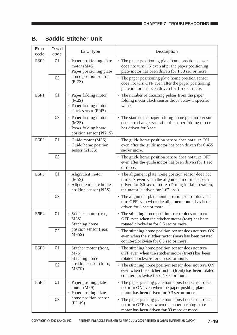
COPYRIGHT © 2000 CANON INC. FINISHER-F1/SADDLE FINISHER-F2 REV. 0 JULY 2000 PRINTED IN JAPAN (IMPRIME AU JAPON) 7-49
CHAPTER 7 TROUBLESHOOTING
B. Saddle Stitcher Unit
Errorcode
E5F0
E5F1
E5F2
E5F3
E5F4
E5F5
E5F6
Detailcode
01
02
01
02
01
02
01
02
01
02
01
02
01
02
Error type
· Paper positioning platemotor (M4S)
· Paper positioning platehome position sensor(PI7S)
· Paper folding motor(M2S)
· Paper folding motorclock sensor (PI4S)
· Paper folding motor(M2S)
· Paper folding homeposition sensor (PI21S)
· Guide motor (M3S)· Guide home position
sensor (PI13S)
· Alignment motor(M5S)
· Alignment plate homeposition sensor (PI5S)
· Stitcher motor (rear,M6S)
· Stitching homeposition sensor (rear,MS5S)
· Stitcher motor (front,M7S)
· Stitching homeposition sensor (front,MS7S)
· Paper pushing platemotor (M8S)
· Paper pushing platehome position sensor(PI14S)
Description
· The paper positioning plate home position sensordoes not turn ON even after the paper positioningplate motor has been driven for 1.33 sec or more.
· The paper positioning plate home position sensordoes not turn OFF even after the paper positioningplate motor has been driven for 1 sec or more.
· The number of detecting pulses from the paperfolding motor clock sensor drops below a specificvalue.
· The state of the paper folding home position sensordoes not change even after the paper folding motorhas driven for 3 sec.
· The guide home position sensor does not turn ONeven after the guide motor has been driven for 0.455sec or more.
· The guide home position sensor does not turn OFFeven after the guide motor has been driven for 1 secor more.
· The alignment plate home position sensor does notturn ON even when the alignment motor has beendriven for 0.5 sec or more. (During initial operation,the motor is driven for 1.67 sec.)
· The alignment plate home position sensor does notturn OFF even when the alignment motor has beendriven for 1 sec or more.
· The stitching home position sensor does not turnOFF even when the stitcher motor (rear) has beenrotated clockwise for 0.5 sec or more.
· The stitching home position sensor does not turn ONeven when the stitcher motor (rear) has been rotatedcounterclockwise for 0.5 sec or more.
· The stitching home position sensor does not turnOFF even when the stitcher motor (front) has beenrotated clockwise for 0.5 sec or more.
· The stitching home position sensor does not turn ONeven when the stitcher motor (front) has been rotatedcounterclockwise for 0.5 sec or more.
· The paper pushing plate home position sensor doesnot turn ON even when the paper pushing platemotor has been driven for 0.3 sec or more.
· The paper pushing plate home position sensor doesnot turn OFF even when the paper pushing platemotor has been driven for 80 msec or more.
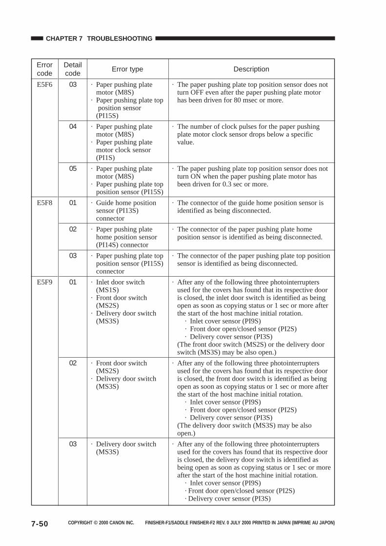
COPYRIGHT © 2000 CANON INC. FINISHER-F1/SADDLE FINISHER-F2 REV. 0 JULY 2000 PRINTED IN JAPAN (IMPRIME AU JAPON)7-50
CHAPTER 7 TROUBLESHOOTING
Errorcode
E5F6
E5F8
E5F9
Detailcode
03
04
05
01
02
03
01
02
03
Error type
· Paper pushing platemotor (M8S)
· Paper pushing plate top position sensor(PI15S)
· Paper pushing platemotor (M8S)
· Paper pushing platemotor clock sensor(PI1S)
· Paper pushing platemotor (M8S)
· Paper pushing plate topposition sensor (PI15S)
· Guide home positionsensor (PI13S)connector
· Paper pushing platehome position sensor(PI14S) connector
· Paper pushing plate topposition sensor (PI15S)connector
· Inlet door switch(MS1S)
· Front door switch(MS2S)
· Delivery door switch(MS3S)
· Front door switch(MS2S)
· Delivery door switch(MS3S)
· Delivery door switch(MS3S)
Description
· The paper pushing plate top position sensor does notturn OFF even after the paper pushing plate motorhas been driven for 80 msec or more.
· The number of clock pulses for the paper pushingplate motor clock sensor drops below a specificvalue.
· The paper pushing plate top position sensor does notturn ON when the paper pushing plate motor hasbeen driven for 0.3 sec or more.
· The connector of the guide home position sensor isidentified as being disconnected.
· The connector of the paper pushing plate homeposition sensor is identified as being disconnected.
· The connector of the paper pushing plate top positionsensor is identified as being disconnected.
· After any of the following three photointerruptersused for the covers has found that its respective dooris closed, the inlet door switch is identified as beingopen as soon as copying status or 1 sec or more afterthe start of the host machine initial rotation. · Inlet cover sensor (PI9S) · Front door open/closed sensor (PI2S) · Delivery cover sensor (PI3S)(The front door switch (MS2S) or the delivery doorswitch (MS3S) may be also open.)
· After any of the following three photointerruptersused for the covers has found that its respective dooris closed, the front door switch is identified as beingopen as soon as copying status or 1 sec or more afterthe start of the host machine initial rotation. · Inlet cover sensor (PI9S) · Front door open/closed sensor (PI2S) · Delivery cover sensor (PI3S)(The delivery door switch (MS3S) may be alsoopen.)
· After any of the following three photointerruptersused for the covers has found that its respective dooris closed, the delivery door switch is identified asbeing open as soon as copying status or 1 sec or moreafter the start of the host machine initial rotation. · Inlet cover sensor (PI9S) · Front door open/closed sensor (PI2S) · Delivery cover sensor (PI3S)
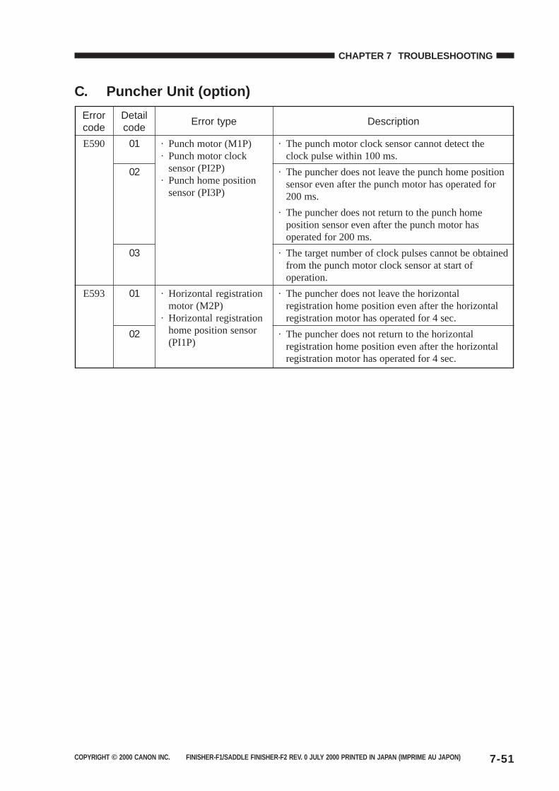
COPYRIGHT © 2000 CANON INC. FINISHER-F1/SADDLE FINISHER-F2 REV. 0 JULY 2000 PRINTED IN JAPAN (IMPRIME AU JAPON) 7-51
CHAPTER 7 TROUBLESHOOTING
C. Puncher Unit (option)
Errorcode
E590
E593
Detailcode
01
02
03
01
02
Error type
· Punch motor (M1P)· Punch motor clock
sensor (PI2P)· Punch home position
sensor (PI3P)
· Horizontal registrationmotor (M2P)
· Horizontal registrationhome position sensor(PI1P)
Description
· The punch motor clock sensor cannot detect theclock pulse within 100 ms.
· The puncher does not leave the punch home positionsensor even after the punch motor has operated for200 ms.
· The puncher does not return to the punch homeposition sensor even after the punch motor hasoperated for 200 ms.
· The target number of clock pulses cannot be obtainedfrom the punch motor clock sensor at start ofoperation.
· The puncher does not leave the horizontalregistration home position even after the horizontalregistration motor has operated for 4 sec.
· The puncher does not return to the horizontalregistration home position even after the horizontalregistration motor has operated for 4 sec.
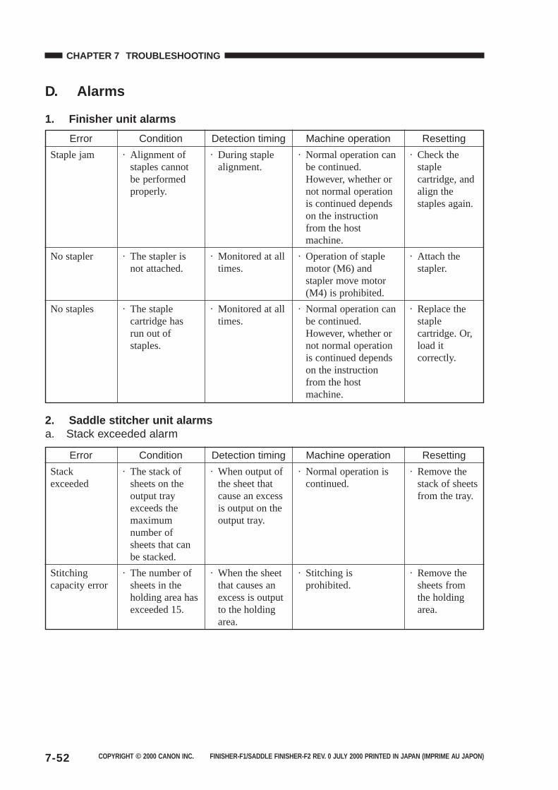
COPYRIGHT © 2000 CANON INC. FINISHER-F1/SADDLE FINISHER-F2 REV. 0 JULY 2000 PRINTED IN JAPAN (IMPRIME AU JAPON)7-52
CHAPTER 7 TROUBLESHOOTING
D. Alarms
1. Finisher unit alarms
2. Saddle stitcher unit alarmsa. Stack exceeded alarm
Error
Staple jam
No stapler
No staples
Condition
· Alignment ofstaples cannotbe performedproperly.
· The stapler isnot attached.
· The staplecartridge hasrun out ofstaples.
Detection timing
· During staplealignment.
· Monitored at alltimes.
· Monitored at alltimes.
Machine operation
· Normal operation canbe continued.However, whether ornot normal operationis continued dependson the instructionfrom the hostmachine.
· Operation of staplemotor (M6) andstapler move motor(M4) is prohibited.
· Normal operation canbe continued.However, whether ornot normal operationis continued dependson the instructionfrom the hostmachine.
Resetting
· Check thestaplecartridge, andalign thestaples again.
· Attach thestapler.
· Replace thestaplecartridge. Or,load itcorrectly.
Error
Stackexceeded
Stitchingcapacity error
Condition
· The stack ofsheets on theoutput trayexceeds themaximumnumber ofsheets that canbe stacked.
· The number ofsheets in theholding area hasexceeded 15.
Detection timing
· When output ofthe sheet thatcause an excessis output on theoutput tray.
· When the sheetthat causes anexcess is outputto the holdingarea.
Machine operation
· Normal operation iscontinued.
· Stitching isprohibited.
Resetting
· Remove thestack of sheetsfrom the tray.
· Remove thesheets fromthe holdingarea.
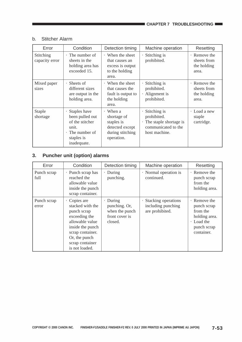
COPYRIGHT © 2000 CANON INC. FINISHER-F1/SADDLE FINISHER-F2 REV. 0 JULY 2000 PRINTED IN JAPAN (IMPRIME AU JAPON) 7-53
CHAPTER 7 TROUBLESHOOTING
b. Stitcher Alarm
3. Puncher unit (option) alarms
Error
Stitchingcapacity error
Mixed papersizes
Stapleshortage
Condition
· The number ofsheets in theholding area hasexceeded 15.
· Sheets ofdifferent sizesare output in theholding area.
· Staples havebeen pulled outof the stitcherunit.
· The number ofstaples isinadequate.
Detection timing
· When the sheetthat causes anexcess is outputto the holdingarea.
· When the sheetthat causes thefault is output tothe holdingarea.
· When ashortage ofstaples isdetected exceptduring stitchingoperation.
Machine operation
· Stitching isprohibited.
· Stitching isprohibited.
· Alignment isprohibited.
· Stitching isprohibited.
· The staple shortage iscommunicated to thehost machine.
Resetting
· Remove thesheets fromthe holdingarea.
· Remove thesheets fromthe holdingarea.
· Load a newstaplecartridge.
Error
Punch scrapfull
Punch scraperror
Condition
· Punch scrap hasreached theallowable valueinside the punchscrap container.
· Copies arestacked with thepunch scrapexceeding theallowable valueinside the punchscrap container.Or, the punchscrap containeris not loaded.
Detection timing
· Duringpunching.
· Duringpunching. Or,when the punchfront cover isclosed.
Machine operation
· Normal operation iscontinued.
· Stacking operationsincluding punchingare prohibited.
Resetting
· Remove thepunch scrapfrom theholding area.
· Remove thepunch scrapfrom theholding area.
· Load thepunch scrapcontainer.
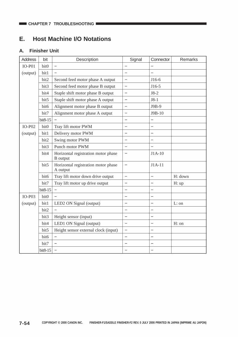
COPYRIGHT © 2000 CANON INC. FINISHER-F1/SADDLE FINISHER-F2 REV. 0 JULY 2000 PRINTED IN JAPAN (IMPRIME AU JAPON)7-54
CHAPTER 7 TROUBLESHOOTING
E. Host Machine I/O Notations
A. Finisher Unit
Address
IO-P01
(output)
IO-P02
(output)
IO-P03
(output)
bit
bit0
bit1
bit2
bit3
bit4
bit5
bit6
bit7
bit8-15
bit0
bit1
bit2
bit3
bit4
bit5
bit6
bit7
bit8-15
bit0
bit1
bit2
bit3
bit4
bit5
bit6
bit7
bit8-15
Description
−−Second feed motor phase A output
Second feed motor phase B output
Staple shift motor phase B output
Staple shift motor phase A output
Alignment motor phase B output
Alignment motor phase A output
−Tray lift motor PWM
Delivery motor PWM
Swing motor PWM
Punch motor PWM
Horizontal registration motor phaseB output
Horizontal registration motor phaseA output
Tray lift motor down drive output
Tray lift motor up drive output
−−LED2 ON Signal (output)
−Height sensor (input)
LED1 ON Signal (output)
Height sensor external clock (input)
−−−
Signal
−−−−−−−−−−−−−−
−
−−−−−−−−−−−−
Connector
−−J16-6
J16-5
J8-2
J8-1
J9B-9
J9B-10
−−−−−J1A-10
J1A-11
−−−−−−−−−−−−
Remarks
H: down
H: up
L: on
H: on
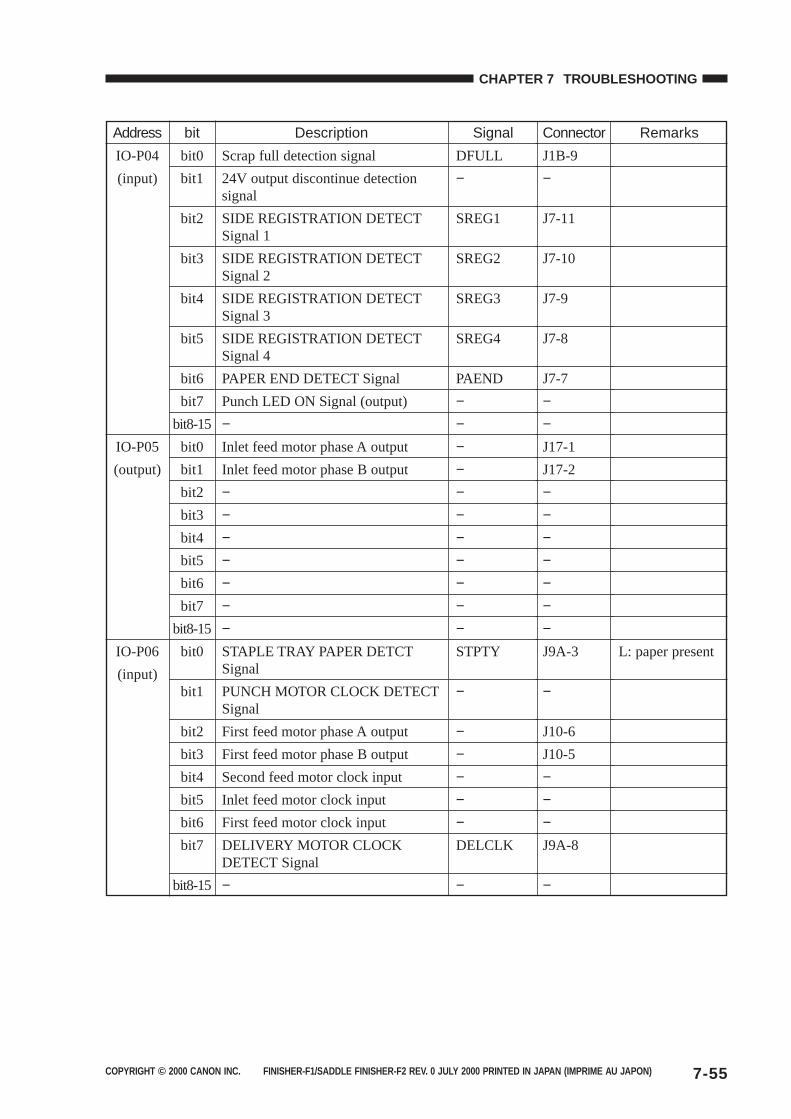
COPYRIGHT © 2000 CANON INC. FINISHER-F1/SADDLE FINISHER-F2 REV. 0 JULY 2000 PRINTED IN JAPAN (IMPRIME AU JAPON) 7-55
CHAPTER 7 TROUBLESHOOTING
Address
IO-P04
(input)
IO-P05
(output)
IO-P06
(input)
bit
bit0
bit1
bit2
bit3
bit4
bit5
bit6
bit7
bit8-15
bit0
bit1
bit2
bit3
bit4
bit5
bit6
bit7
bit8-15
bit0
bit1
bit2
bit3
bit4
bit5
bit6
bit7
bit8-15
Description
Scrap full detection signal
24V output discontinue detectionsignal
SIDE REGISTRATION DETECTSignal 1
SIDE REGISTRATION DETECTSignal 2
SIDE REGISTRATION DETECTSignal 3
SIDE REGISTRATION DETECTSignal 4
PAPER END DETECT Signal
Punch LED ON Signal (output)
−Inlet feed motor phase A output
Inlet feed motor phase B output
−−−−−−−STAPLE TRAY PAPER DETCTSignal
PUNCH MOTOR CLOCK DETECTSignal
First feed motor phase A output
First feed motor phase B output
Second feed motor clock input
Inlet feed motor clock input
First feed motor clock input
DELIVERY MOTOR CLOCKDETECT Signal
−
Signal
DFULL
−
SREG1
SREG2
SREG3
SREG4
PAEND
−−−−−−−−−−−STPTY
−
−−−−−DELCLK
−
Connector
J1B-9
−
J7-11
J7-10
J7-9
J7-8
J7-7
−−J17-1
J17-2
−−−−−−−J9A-3
−
J10-6
J10-5
−−−J9A-8
−
Remarks
L: paper present
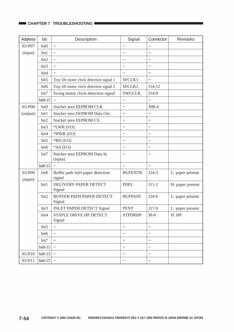
COPYRIGHT © 2000 CANON INC. FINISHER-F1/SADDLE FINISHER-F2 REV. 0 JULY 2000 PRINTED IN JAPAN (IMPRIME AU JAPON)7-56
CHAPTER 7 TROUBLESHOOTING
Address
IO-P07
(input)
IO-P08
(output)
IO-P09
(input)
IO-P10
IO-P11
bit
bit0
bit1
bit2
bit3
bit4
bit5
bit6
bit7
bit8-15
bit0
bit1
bit2
bit3
bit4
bit5
bit6
bit7
bit8-15
bit0
bit1
bit2
bit3
bit4
bit5
bit6
bit7
bit8-15
bit0-15
bit0-15
Description
−−−−−Tray lift motor clock detection signal 1
Tray lift motor clock detection signal 2
Swing motor clock detection signal
−Stacker area EEPROM CLK
Stacker area EEPROM Data Out
Stacker area EEPROM CS
*LWR (I/O)
*HWR (I/O)
*RD (I/O)
*AS (I/O)
Stacker area EEPROM Data In(input)
−Buffer path inlet paper detectionsignal
DELIVERY PAPER DETECTSignal
BUFFER PATH PAPER DETECTSignal
INLET PAPER DETECT Signal
STAPLE DRIVE HP DETECTSignal
−−−−−−
Signal
−−−−−SFCLK1
SFCLK2
SWGCLK
−−−−−−−−−
−BUFENTR
PDEL
BUFPASS
PENT
STPDRHP
−−−−−−
Connector
−−−−−−J14-12
J14-9
−J9B-4
−−−−−−−
−J24-3
J11-2
J24-6
J17-9
J8-8
−−−−−−
Remarks
L: paper present
H: paper present
L: paper present
L: paper present
H: HP
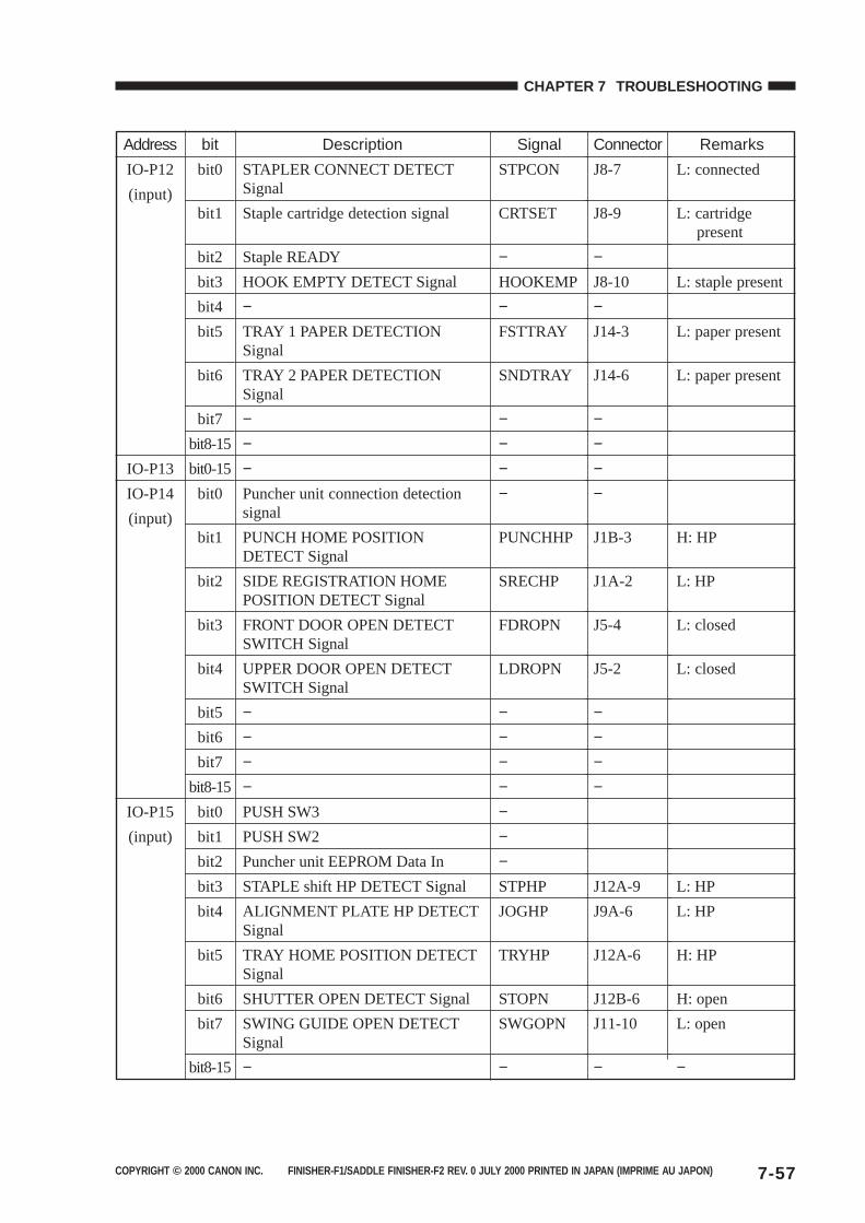
COPYRIGHT © 2000 CANON INC. FINISHER-F1/SADDLE FINISHER-F2 REV. 0 JULY 2000 PRINTED IN JAPAN (IMPRIME AU JAPON) 7-57
CHAPTER 7 TROUBLESHOOTING
Address
IO-P12
(input)
IO-P13
IO-P14
(input)
IO-P15
(input)
bit
bit0
bit1
bit2
bit3
bit4
bit5
bit6
bit7
bit8-15
bit0-15
bit0
bit1
bit2
bit3
bit4
bit5
bit6
bit7
bit8-15
bit0
bit1
bit2
bit3
bit4
bit5
bit6
bit7
bit8-15
Description
STAPLER CONNECT DETECTSignal
Staple cartridge detection signal
Staple READY
HOOK EMPTY DETECT Signal
−TRAY 1 PAPER DETECTIONSignal
TRAY 2 PAPER DETECTIONSignal
−−−Puncher unit connection detectionsignal
PUNCH HOME POSITIONDETECT Signal
SIDE REGISTRATION HOMEPOSITION DETECT Signal
FRONT DOOR OPEN DETECTSWITCH Signal
UPPER DOOR OPEN DETECTSWITCH Signal
−−−−PUSH SW3
PUSH SW2
Puncher unit EEPROM Data In
STAPLE shift HP DETECT Signal
ALIGNMENT PLATE HP DETECTSignal
TRAY HOME POSITION DETECTSignal
SHUTTER OPEN DETECT Signal
SWING GUIDE OPEN DETECTSignal
−
Signal
STPCON
CRTSET
−HOOKEMP
−FSTTRAY
SNDTRAY
−−−−
PUNCHHP
SRECHP
FDROPN
LDROPN
−−−−−−−STPHP
JOGHP
TRYHP
STOPN
SWGOPN
−
Connector
J8-7
J8-9
−J8-10
−J14-3
J14-6
−−−−
J1B-3
J1A-2
J5-4
J5-2
−−−−
J12A-9
J9A-6
J12A-6
J12B-6
J11-10
−
Remarks
L: connected
L: cartridge present
L: staple present
L: paper present
L: paper present
H: HP
L: HP
L: closed
L: closed
L: HP
L: HP
H: HP
H: open
L: open
−
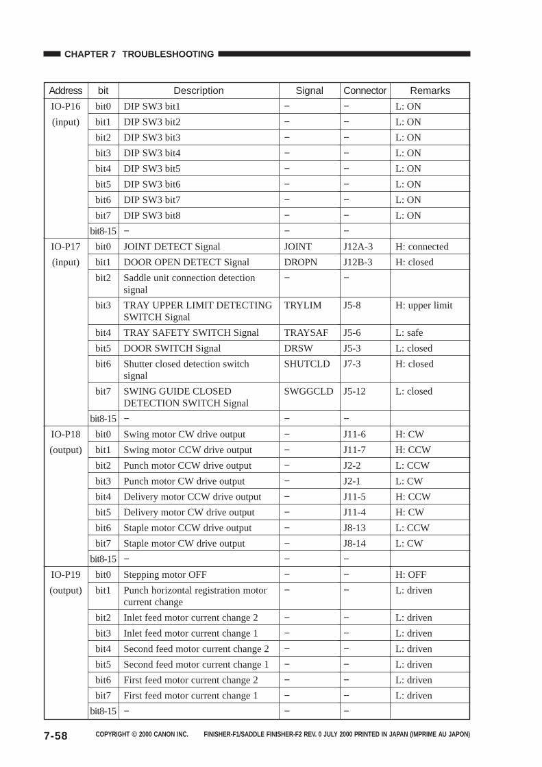
COPYRIGHT © 2000 CANON INC. FINISHER-F1/SADDLE FINISHER-F2 REV. 0 JULY 2000 PRINTED IN JAPAN (IMPRIME AU JAPON)7-58
CHAPTER 7 TROUBLESHOOTING
Address
IO-P16
(input)
IO-P17
(input)
IO-P18
(output)
IO-P19
(output)
bit
bit0
bit1
bit2
bit3
bit4
bit5
bit6
bit7
bit8-15
bit0
bit1
bit2
bit3
bit4
bit5
bit6
bit7
bit8-15
bit0
bit1
bit2
bit3
bit4
bit5
bit6
bit7
bit8-15
bit0
bit1
bit2
bit3
bit4
bit5
bit6
bit7
bit8-15
Description
DIP SW3 bit1
DIP SW3 bit2
DIP SW3 bit3
DIP SW3 bit4
DIP SW3 bit5
DIP SW3 bit6
DIP SW3 bit7
DIP SW3 bit8
−JOINT DETECT Signal
DOOR OPEN DETECT Signal
Saddle unit connection detectionsignal
TRAY UPPER LIMIT DETECTINGSWITCH Signal
TRAY SAFETY SWITCH Signal
DOOR SWITCH Signal
Shutter closed detection switchsignal
SWING GUIDE CLOSEDDETECTION SWITCH Signal
−Swing motor CW drive output
Swing motor CCW drive output
Punch motor CCW drive output
Punch motor CW drive output
Delivery motor CCW drive output
Delivery motor CW drive output
Staple motor CCW drive output
Staple motor CW drive output
−Stepping motor OFF
Punch horizontal registration motorcurrent change
Inlet feed motor current change 2
Inlet feed motor current change 1
Second feed motor current change 2
Second feed motor current change 1
First feed motor current change 2
First feed motor current change 1
−
Signal
−−−−−−−−−JOINT
DROPN
−
TRYLIM
TRAYSAF
DRSW
SHUTCLD
SWGGCLD
−−−−−−−−−−−−
−−−−−−−
Connector
−−−−−−−−−J12A-3
J12B-3
−
J5-8
J5-6
J5-3
J7-3
J5-12
−J11-6
J11-7
J2-2
J2-1
J11-5
J11-4
J8-13
J8-14
−−−
−−−−−−−
Remarks
L: ON
L: ON
L: ON
L: ON
L: ON
L: ON
L: ON
L: ON
H: connected
H: closed
H: upper limit
L: safe
L: closed
H: closed
L: closed
H: CW
H: CCW
L: CCW
L: CW
H: CCW
H: CW
L: CCW
L: CW
H: OFF
L: driven
L: driven
L: driven
L: driven
L: driven
L: driven
L: driven
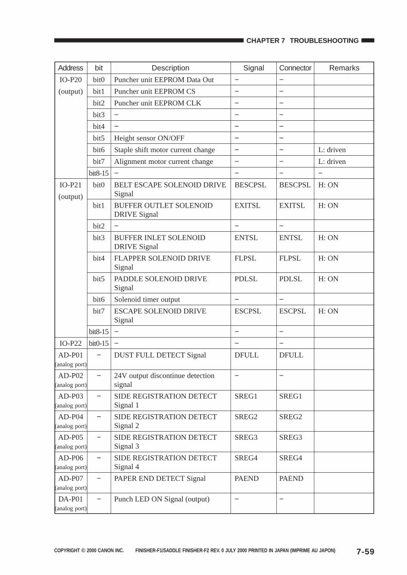
COPYRIGHT © 2000 CANON INC. FINISHER-F1/SADDLE FINISHER-F2 REV. 0 JULY 2000 PRINTED IN JAPAN (IMPRIME AU JAPON) 7-59
CHAPTER 7 TROUBLESHOOTING
Address
IO-P20
(output)
IO-P21
(output)
IO-P22
AD-P01(analog port)
AD-P02(analog port)
AD-P03(analog port)
AD-P04(analog port)
AD-P05(analog port)
AD-P06(analog port)
AD-P07(analog port)
DA-P01(analog port)
bit
bit0
bit1
bit2
bit3
bit4
bit5
bit6
bit7
bit8-15
bit0
bit1
bit2
bit3
bit4
bit5
bit6
bit7
bit8-15
bit0-15
−
−
−
−
−
−
−
−
Description
Puncher unit EEPROM Data Out
Puncher unit EEPROM CS
Puncher unit EEPROM CLK
−−Height sensor ON/OFF
Staple shift motor current change
Alignment motor current change
−BELT ESCAPE SOLENOID DRIVESignal
BUFFER OUTLET SOLENOIDDRIVE Signal
−BUFFER INLET SOLENOIDDRIVE Signal
FLAPPER SOLENOID DRIVESignal
PADDLE SOLENOID DRIVESignal
Solenoid timer output
ESCAPE SOLENOID DRIVESignal
−−DUST FULL DETECT Signal
24V output discontinue detectionsignal
SIDE REGISTRATION DETECTSignal 1
SIDE REGISTRATION DETECTSignal 2
SIDE REGISTRATION DETECTSignal 3
SIDE REGISTRATION DETECTSignal 4
PAPER END DETECT Signal
Punch LED ON Signal (output)
Signal
−−−−−−−−−BESCPSL
EXITSL
−ENTSL
FLPSL
PDLSL
−ESCPSL
−−DFULL
−
SREG1
SREG2
SREG3
SREG4
PAEND
−
Connector
−−−−−−−−−BESCPSL
EXITSL
−ENTSL
FLPSL
PDLSL
−ESCPSL
−−DFULL
−
SREG1
SREG2
SREG3
SREG4
PAEND
−
Remarks
L: driven
L: driven
−H: ON
H: ON
H: ON
H: ON
H: ON
H: ON
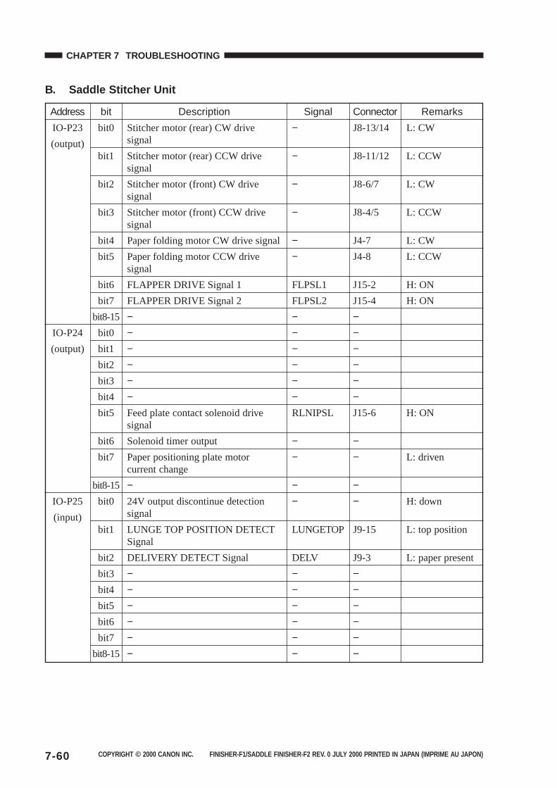
COPYRIGHT © 2000 CANON INC. FINISHER-F1/SADDLE FINISHER-F2 REV. 0 JULY 2000 PRINTED IN JAPAN (IMPRIME AU JAPON)7-60
CHAPTER 7 TROUBLESHOOTING
B. Saddle Stitcher Unit
Address
IO-P23
(output)
IO-P24
(output)
IO-P25
(input)
bit
bit0
bit1
bit2
bit3
bit4
bit5
bit6
bit7
bit8-15
bit0
bit1
bit2
bit3
bit4
bit5
bit6
bit7
bit8-15
bit0
bit1
bit2
bit3
bit4
bit5
bit6
bit7
bit8-15
Description
Stitcher motor (rear) CW drivesignal
Stitcher motor (rear) CCW drivesignal
Stitcher motor (front) CW drivesignal
Stitcher motor (front) CCW drivesignal
Paper folding motor CW drive signal
Paper folding motor CCW drivesignal
FLAPPER DRIVE Signal 1
FLAPPER DRIVE Signal 2
−−−−−−Feed plate contact solenoid drivesignal
Solenoid timer output
Paper positioning plate motorcurrent change
−24V output discontinue detectionsignal
LUNGE TOP POSITION DETECTSignal
DELIVERY DETECT Signal
−−−−−−
Signal
−
−
−
−
−−
FLPSL1
FLPSL2
−−−−−−RLNIPSL
−−
−−
LUNGETOP
DELV
−−−−−−
Connector
J8-13/14
J8-11/12
J8-6/7
J8-4/5
J4-7
J4-8
J15-2
J15-4
−−−−−−J15-6
−−
−−
J9-15
J9-3
−−−−−−
Remarks
L: CW
L: CCW
L: CW
L: CCW
L: CW
L: CCW
H: ON
H: ON
H: ON
L: driven
H: down
L: top position
L: paper present
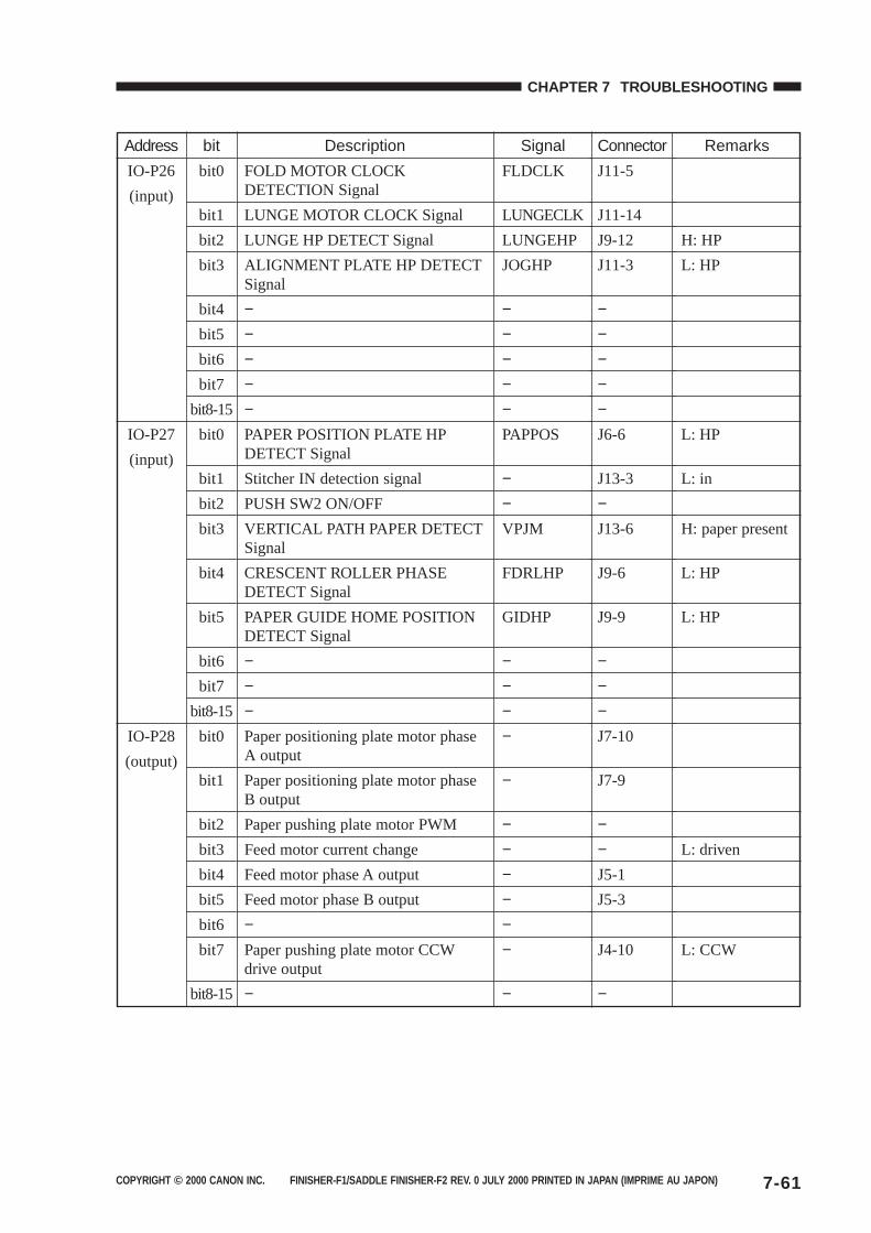
COPYRIGHT © 2000 CANON INC. FINISHER-F1/SADDLE FINISHER-F2 REV. 0 JULY 2000 PRINTED IN JAPAN (IMPRIME AU JAPON) 7-61
CHAPTER 7 TROUBLESHOOTING
Address
IO-P26
(input)
IO-P27
(input)
IO-P28
(output)
bit
bit0
bit1
bit2
bit3
bit4
bit5
bit6
bit7
bit8-15
bit0
bit1
bit2
bit3
bit4
bit5
bit6
bit7
bit8-15
bit0
bit1
bit2
bit3
bit4
bit5
bit6
bit7
bit8-15
Description
FOLD MOTOR CLOCKDETECTION Signal
LUNGE MOTOR CLOCK Signal
LUNGE HP DETECT Signal
ALIGNMENT PLATE HP DETECTSignal
−−−−−PAPER POSITION PLATE HPDETECT Signal
Stitcher IN detection signal
PUSH SW2 ON/OFF
VERTICAL PATH PAPER DETECTSignal
CRESCENT ROLLER PHASEDETECT Signal
PAPER GUIDE HOME POSITIONDETECT Signal
−−−Paper positioning plate motor phaseA output
Paper positioning plate motor phaseB output
Paper pushing plate motor PWM
Feed motor current change
Feed motor phase A output
Feed motor phase B output
−Paper pushing plate motor CCWdrive output
−
Signal
FLDCLK
LUNGECLK
LUNGEHP
JOGHP
−−−−−PAPPOS
−−VPJM
FDRLHP
GIDHP
−−−−
−
−−−−−−
−
Connector
J11-5
J11-14
J9-12
J11-3
−−−−−J6-6
J13-3
−J13-6
J9-6
J9-9
−−−J7-10
J7-9
−−J5-1
J5-3
J4-10
−
Remarks
H: HP
L: HP
L: HP
L: in
H: paper present
L: HP
L: HP
L: driven
L: CCW
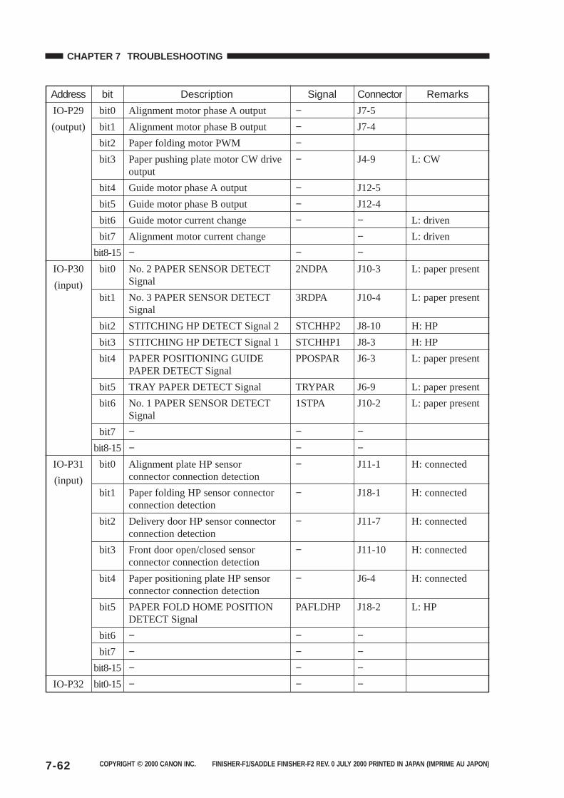
COPYRIGHT © 2000 CANON INC. FINISHER-F1/SADDLE FINISHER-F2 REV. 0 JULY 2000 PRINTED IN JAPAN (IMPRIME AU JAPON)7-62
CHAPTER 7 TROUBLESHOOTING
Address
IO-P29
(output)
IO-P30
(input)
IO-P31
(input)
IO-P32
bit
bit0
bit1
bit2
bit3
bit4
bit5
bit6
bit7
bit8-15
bit0
bit1
bit2
bit3
bit4
bit5
bit6
bit7
bit8-15
bit0
bit1
bit2
bit3
bit4
bit5
bit6
bit7
bit8-15
bit0-15
Description
Alignment motor phase A output
Alignment motor phase B output
Paper folding motor PWM
Paper pushing plate motor CW driveoutput
Guide motor phase A output
Guide motor phase B output
Guide motor current change
Alignment motor current change
−No. 2 PAPER SENSOR DETECTSignal
No. 3 PAPER SENSOR DETECTSignal
STITCHING HP DETECT Signal 2
STITCHING HP DETECT Signal 1
PAPER POSITIONING GUIDEPAPER DETECT Signal
TRAY PAPER DETECT Signal
No. 1 PAPER SENSOR DETECTSignal
−−Alignment plate HP sensorconnector connection detection
Paper folding HP sensor connectorconnection detection
Delivery door HP sensor connectorconnection detection
Front door open/closed sensorconnector connection detection
Paper positioning plate HP sensorconnector connection detection
PAPER FOLD HOME POSITIONDETECT Signal
−−−−
Signal
−−−−
−−−
−2NDPA
3RDPA
STCHHP2
STCHHP1
PPOSPAR
TRYPAR
1STPA
−−−
−
−
−
−
PAFLDHP
−−−−
Connector
J7-5
J7-4
J4-9
J12-5
J12-4
−−−J10-3
J10-4
J8-10
J8-3
J6-3
J6-9
J10-2
−−J11-1
J18-1
J11-7
J11-10
J6-4
J18-2
−−−−
Remarks
L: CW
L: driven
L: driven
L: paper present
L: paper present
H: HP
H: HP
L: paper present
L: paper present
L: paper present
H: connected
H: connected
H: connected
H: connected
H: connected
L: HP
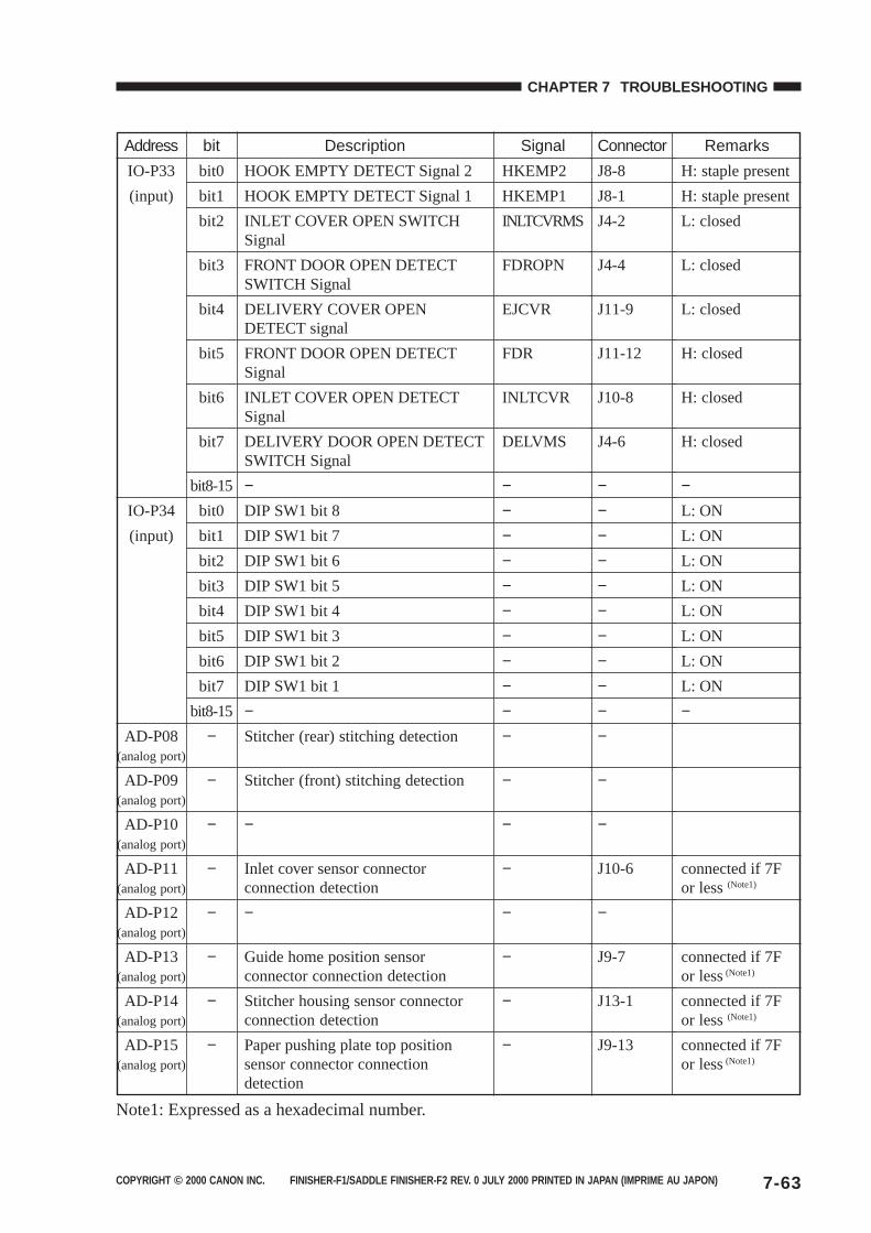
COPYRIGHT © 2000 CANON INC. FINISHER-F1/SADDLE FINISHER-F2 REV. 0 JULY 2000 PRINTED IN JAPAN (IMPRIME AU JAPON) 7-63
CHAPTER 7 TROUBLESHOOTING
Note1: Expressed as a hexadecimal number.
Address
IO-P33
(input)
IO-P34
(input)
AD-P08(analog port)
AD-P09(analog port)
AD-P10(analog port)
AD-P11(analog port)
AD-P12(analog port)
AD-P13(analog port)
AD-P14(analog port)
AD-P15(analog port)
bit
bit0
bit1
bit2
bit3
bit4
bit5
bit6
bit7
bit8-15
bit0
bit1
bit2
bit3
bit4
bit5
bit6
bit7
bit8-15
−
−
−
−
−
−
−
−
Description
HOOK EMPTY DETECT Signal 2
HOOK EMPTY DETECT Signal 1
INLET COVER OPEN SWITCHSignal
FRONT DOOR OPEN DETECTSWITCH Signal
DELIVERY COVER OPENDETECT signal
FRONT DOOR OPEN DETECTSignal
INLET COVER OPEN DETECTSignal
DELIVERY DOOR OPEN DETECTSWITCH Signal
−DIP SW1 bit 8
DIP SW1 bit 7
DIP SW1 bit 6
DIP SW1 bit 5
DIP SW1 bit 4
DIP SW1 bit 3
DIP SW1 bit 2
DIP SW1 bit 1
−Stitcher (rear) stitching detection
Stitcher (front) stitching detection
−
Inlet cover sensor connectorconnection detection
−
Guide home position sensorconnector connection detection
Stitcher housing sensor connectorconnection detection
Paper pushing plate top positionsensor connector connectiondetection
Signal
HKEMP2
HKEMP1
INLTCVRMS
FDROPN
EJCVR
FDR
INLTCVR
DELVMS
−−−−−−−−−−−
−
−
−
−
−
−
−
Connector
J8-8
J8-1
J4-2
J4-4
J11-9
J11-12
J10-8
J4-6
−−−−−−−−−−−
−
−
J10-6
−
J9-7
J13-1
J9-13
Remarks
H: staple present
H: staple present
L: closed
L: closed
L: closed
H: closed
H: closed
H: closed
−L: ON
L: ON
L: ON
L: ON
L: ON
L: ON
L: ON
L: ON
−
connected if 7For less (Note1)
connected if 7For less (Note1)
connected if 7For less (Note1)
connected if 7For less (Note1)


COPYRIGHT © 2000 CANON INC. FINISHER-F1/SADDLE FINISHER-F2 REV. 0 JULY 2000 PRINTED IN JAPAN (IMPRIME AU JAPON)
APPENDIX
A. FINISHER UNIT GENERALTIMING CHART ........................ A-1
B. SADDLE STITCHER UNITGENERAL TIMING CHART ...... A-2
C. PUNCHER UNIT (opiton)GENERAL TIMING CHART ...... A-3
D. SIGNAL ANDABBREVIATIONS ...................... A-4
E. FINISHER UNIT CIRCUITDIAGRAM .................................. A-5
F. SADDLE STITCHER UNITCIRCUIT DIAGRAM ................ A-19
G. PUNCHER UNIT (opiton)CIRCUIT DIAGRAM ................ A-29
H. SOLVENTS AND OILS............ A-38

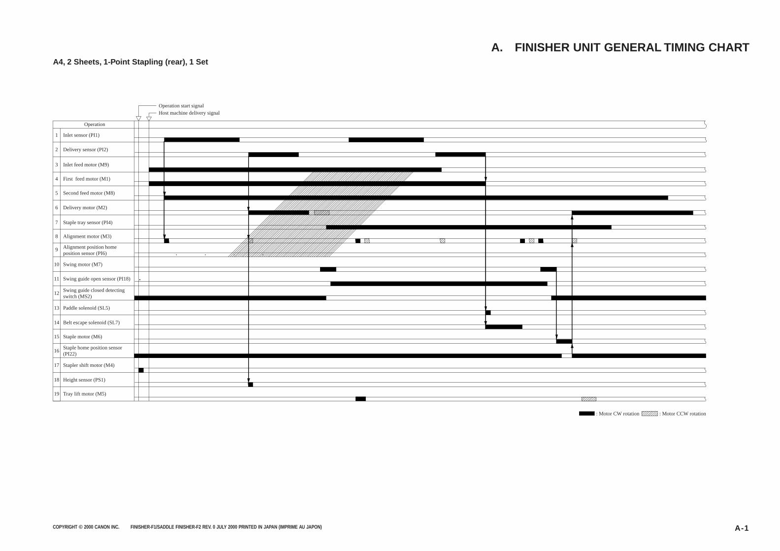
COPYRIGHT © 2000 CANON INC. FINISHER-F1/SADDLE FINISHER-F2 REV. 0 JULY 2000 PRINTED IN JAPAN (IMPRIME AU JAPON) A-1
A4, 2 Sheets, 1-Point Stapling (rear), 1 Set
A. FINISHER UNIT GENERAL TIMING CHART
1
2
4
3
5
6
8
7
9
10
12
11
13
14
16
15
17
18
19
Operation
Inlet sensor (PI1)
Delivery sensor (PI2)
Inlet feed motor (M9)
First feed motor (M1)
Second feed motor (M8)
Delivery motor (M2)
Staple tray sensor (PI4)
Alignment motor (M3)
Alignment position home position sensor (PI6)
Swing motor (M7)
Swing guide open sensor (PI18)
Swing guide closed detecting switch (MS2)
Paddle solenoid (SL5)
Belt escape solenoid (SL7)
Staple motor (M6)
Staple home position sensor (PI22)
Stapler shift motor (M4)
Height sensor (PS1)
Tray lift motor (M5)
Operation start signalHost machine delivery signal
: Motor CW rotation : Motor CCW rotation
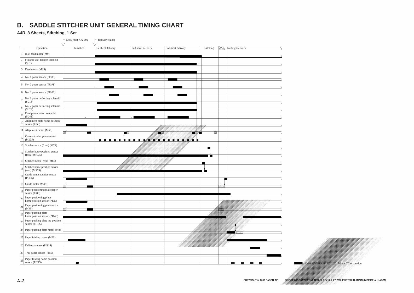
COPYRIGHT © 2000 CANON INC. FINISHER-F1/SADDLE FINISHER-F2 REV. 0 JULY 2000 PRINTED IN JAPAN (IMPRIME AU JAPON)A-2
A4R, 3 Sheets, Stitching, 1 Set
B. SADDLE STITCHER UNIT GENERAL TIMING CHART
1
2
4
3
5
6
8
7
9
10
12
11
13
14
16
15
17
18
20
19
21
22
24
23
25
26
27
28
Operation
Inlet feed motor (M9)
Finisher unit flapper solenoid (SL1)
Feed motor (M1S)
No. 1 paper sensor (PI18S)
No. 2 paper sensor (PI19S)
No. 3 paper sensor (PI20S)
No. 1 paper deflecting solenoid (SL1S)
No. 2 paper deflecting solenoid (SL2S)
Feed plate contact solenoid (SL4S)
Alignment plate home position sensor (PI5S)
Alignment motor (M5S)
Crescent roller phase sensor (PI12S)
Stitcher motor (front) (M7S)
Stitcher home position sensor (front) (MS7S)
Stitcher motor (rear) (M6S)
Stitcher home position sensor (rear) (MS5S)
Guide home position sensor (PI13S)
Guide motor (M3S)
Paper positioning plate paper sensor (PI8S)
Paper positioning plate home position sensor (PI7S)
Paper positioning plate motor (M4S)
Paper pushing plate home position sensor (PI14S)
Paper pushing plate top position sensor (PI15S)
Paper pushing plate motor (M8S)
Paper folding motor (M2S)
Delivery sensor (PI11S)
Tray paper sensor (PI6S)
Paper folding home position sensor (PI21S)
Copy Start Key ON
Initialize
Delivery signal
1st sheet delivery 2nd sheet delivery 3rd sheet delivery StitchingStack feeding Folding,/delivery
: Motor CW rotation : Motor CCW rotation
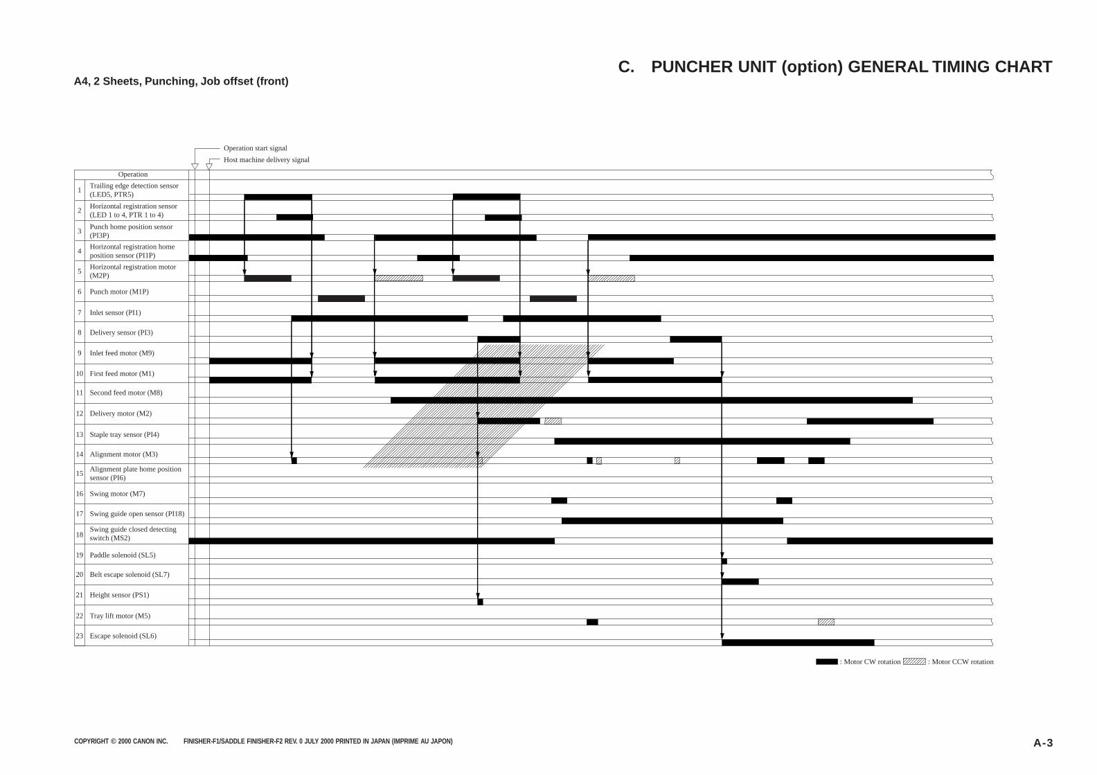
COPYRIGHT © 2000 CANON INC. FINISHER-F1/SADDLE FINISHER-F2 REV. 0 JULY 2000 PRINTED IN JAPAN (IMPRIME AU JAPON) A-3
A4, 2 Sheets, Punching, Job offset (front)C. PUNCHER UNIT (option) GENERAL TIMING CHART
1
2
4
3
5
6
8
7
9
10
12
11
13
14
16
15
17
18
19
20
21
22
23
Operation
Trailing edge detection sensor (LED5, PTR5)
Horizontal registration sensor (LED 1 to 4, PTR 1 to 4)
Punch home position sensor (PI3P)
Horizontal registration home position sensor (PI1P)
Horizontal registration motor (M2P)
Punch motor (M1P)
Inlet sensor (PI1)
Delivery sensor (PI3)
Inlet feed motor (M9)
First feed motor (M1)
Second feed motor (M8)
Delivery motor (M2)
Staple tray sensor (PI4)
Alignment motor (M3)
Alignment plate home position sensor (PI6)
Swing motor (M7)
Swing guide open sensor (PI18)
Swing guide closed detecting switch (MS2)
Paddle solenoid (SL5)
Belt escape solenoid (SL7)
Height sensor (PS1)
Tray lift motor (M5)
Escape solenoid (SL6)
Operation start signal
Host machine delivery signal
: Motor CW rotation : Motor CCW rotation
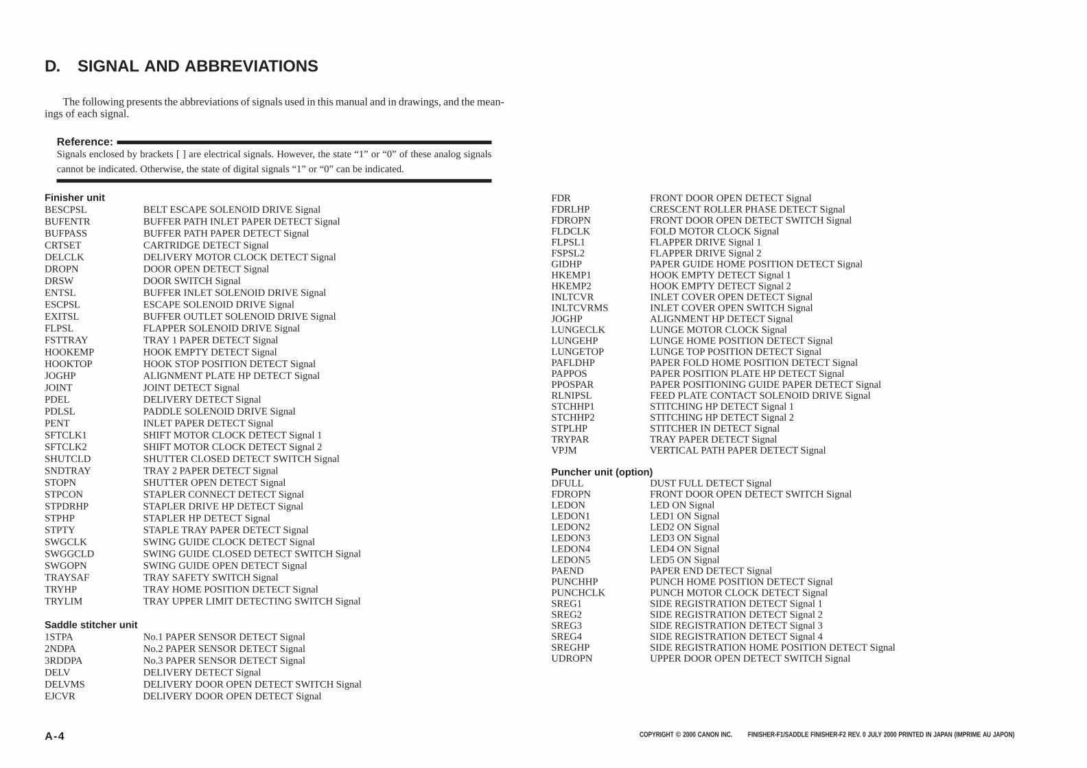
COPYRIGHT © 2000 CANON INC. FINISHER-F1/SADDLE FINISHER-F2 REV. 0 JULY 2000 PRINTED IN JAPAN (IMPRIME AU JAPON)A-4
D. SIGNAL AND ABBREVIATIONS
Finisher unitBESCPSL BELT ESCAPE SOLENOID DRIVE SignalBUFENTR BUFFER PATH INLET PAPER DETECT SignalBUFPASS BUFFER PATH PAPER DETECT SignalCRTSET CARTRIDGE DETECT SignalDELCLK DELIVERY MOTOR CLOCK DETECT SignalDROPN DOOR OPEN DETECT SignalDRSW DOOR SWITCH SignalENTSL BUFFER INLET SOLENOID DRIVE SignalESCPSL ESCAPE SOLENOID DRIVE SignalEXITSL BUFFER OUTLET SOLENOID DRIVE SignalFLPSL FLAPPER SOLENOID DRIVE SignalFSTTRAY TRAY 1 PAPER DETECT SignalHOOKEMP HOOK EMPTY DETECT SignalHOOKTOP HOOK STOP POSITION DETECT SignalJOGHP ALIGNMENT PLATE HP DETECT SignalJOINT JOINT DETECT SignalPDEL DELIVERY DETECT SignalPDLSL PADDLE SOLENOID DRIVE SignalPENT INLET PAPER DETECT SignalSFTCLK1 SHIFT MOTOR CLOCK DETECT Signal 1SFTCLK2 SHIFT MOTOR CLOCK DETECT Signal 2SHUTCLD SHUTTER CLOSED DETECT SWITCH SignalSNDTRAY TRAY 2 PAPER DETECT SignalSTOPN SHUTTER OPEN DETECT SignalSTPCON STAPLER CONNECT DETECT SignalSTPDRHP STAPLER DRIVE HP DETECT SignalSTPHP STAPLER HP DETECT SignalSTPTY STAPLE TRAY PAPER DETECT SignalSWGCLK SWING GUIDE CLOCK DETECT SignalSWGGCLD SWING GUIDE CLOSED DETECT SWITCH SignalSWGOPN SWING GUIDE OPEN DETECT SignalTRAYSAF TRAY SAFETY SWITCH SignalTRYHP TRAY HOME POSITION DETECT SignalTRYLIM TRAY UPPER LIMIT DETECTING SWITCH Signal
Saddle stitcher unit1STPA No.1 PAPER SENSOR DETECT Signal2NDPA No.2 PAPER SENSOR DETECT Signal3RDDPA No.3 PAPER SENSOR DETECT SignalDELV DELIVERY DETECT SignalDELVMS DELIVERY DOOR OPEN DETECT SWITCH SignalEJCVR DELIVERY DOOR OPEN DETECT Signal
The following presents the abbreviations of signals used in this manual and in drawings, and the mean-ings of each signal.
Reference:Signals enclosed by brackets [ ] are electrical signals. However, the state “1” or “0” of these analog signals
cannot be indicated. Otherwise, the state of digital signals “1” or “0” can be indicated.
FDR FRONT DOOR OPEN DETECT SignalFDRLHP CRESCENT ROLLER PHASE DETECT SignalFDROPN FRONT DOOR OPEN DETECT SWITCH SignalFLDCLK FOLD MOTOR CLOCK SignalFLPSL1 FLAPPER DRIVE Signal 1FSPSL2 FLAPPER DRIVE Signal 2GIDHP PAPER GUIDE HOME POSITION DETECT SignalHKEMP1 HOOK EMPTY DETECT Signal 1HKEMP2 HOOK EMPTY DETECT Signal 2INLTCVR INLET COVER OPEN DETECT SignalINLTCVRMS INLET COVER OPEN SWITCH SignalJOGHP ALIGNMENT HP DETECT SignalLUNGECLK LUNGE MOTOR CLOCK SignalLUNGEHP LUNGE HOME POSITION DETECT SignalLUNGETOP LUNGE TOP POSITION DETECT SignalPAFLDHP PAPER FOLD HOME POSITION DETECT SignalPAPPOS PAPER POSITION PLATE HP DETECT SignalPPOSPAR PAPER POSITIONING GUIDE PAPER DETECT SignalRLNIPSL FEED PLATE CONTACT SOLENOID DRIVE SignalSTCHHP1 STITCHING HP DETECT Signal 1STCHHP2 STITCHING HP DETECT Signal 2STPLHP STITCHER IN DETECT SignalTRYPAR TRAY PAPER DETECT SignalVPJM VERTICAL PATH PAPER DETECT Signal
Puncher unit (option)DFULL DUST FULL DETECT SignalFDROPN FRONT DOOR OPEN DETECT SWITCH SignalLEDON LED ON SignalLEDON1 LED1 ON SignalLEDON2 LED2 ON SignalLEDON3 LED3 ON SignalLEDON4 LED4 ON SignalLEDON5 LED5 ON SignalPAEND PAPER END DETECT SignalPUNCHHP PUNCH HOME POSITION DETECT SignalPUNCHCLK PUNCH MOTOR CLOCK DETECT SignalSREG1 SIDE REGISTRATION DETECT Signal 1SREG2 SIDE REGISTRATION DETECT Signal 2SREG3 SIDE REGISTRATION DETECT Signal 3SREG4 SIDE REGISTRATION DETECT Signal 4SREGHP SIDE REGISTRATION HOME POSITION DETECT SignalUDROPN UPPER DOOR OPEN DETECT SWITCH Signal
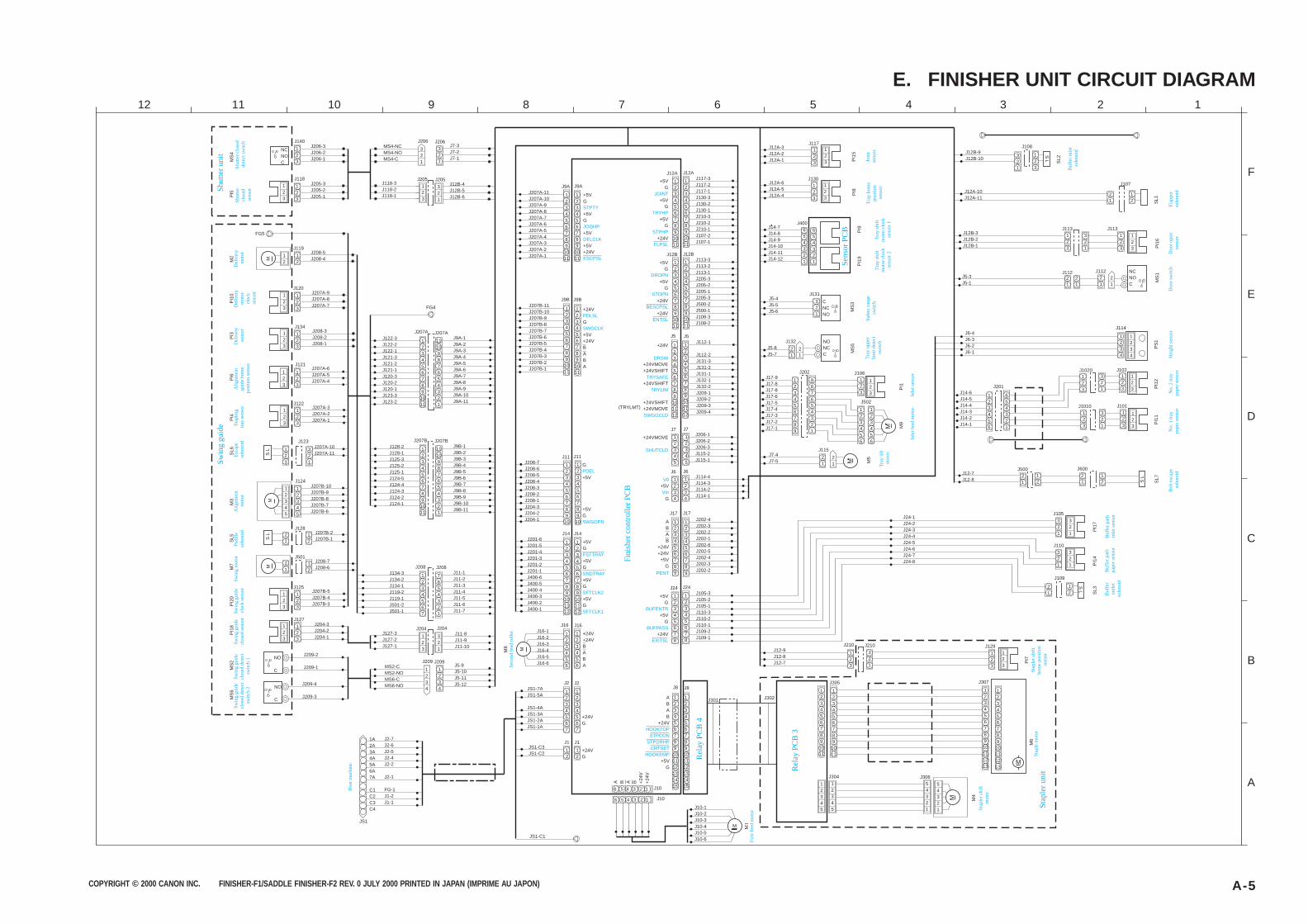
COPYRIGHT © 2000 CANON INC. FINISHER-F1/SADDLE FINISHER-F2 REV. 0 JULY 2000 PRINTED IN JAPAN (IMPRIME AU JAPON) A-5
E. FINISHER UNIT CIRCUIT DIAGRAM
PI1
7
PI7
PI1
2P
I11
PS
1
PI1
4S
L3
SL1
SL2
J10-1J10-2J10-3J10-4J10-5J10-6
M
12345
12345
54321
54321
M
123456789
10111213
123456789
10111213
123
123
321
123
J210 J129
J1020 J102
12
21
J114
123
321
123
123
321
123
123
123
1234
1234
654321
123456
J101J1010
J6-4J6-3J6-2J6-1
J201
J12A-10J12A-11
321
123
21
12
321
321
321
321
J24-1J24-2J24-3J24-4J24-5J24-6J24-7J24-8
J12B-9J12B-10
M4
M6
PI1
6M
S1
MS
3M
S5
M5
PI8
PI1
5P
I9P
I19
J14-6J14-5J14-4J14-3J14-2J14-1
123
123
J12A-3J12A-2J12A-1
J12A-6J12A-5J12A-4
123
123
J14-7J14-8J14-9J14-10J14-11J14-12
654321
654321
J400
J117
J130
J12B-3J12B-2J12B-1
123
321
123
123
J113 J113
J5-3J5-1
21
21
21
NCNOC
J5-4J5-5J5-6
321
CNCNO
J5-8J5-7
21
21
NONCC
J7-4J7-5
21
21
M
M
J12-9J12-8J12-7
123456789
1011
123456789
1011
J302J301123456789
101112131415
123456789
101112131415
J304
J305
J306
M
J307
J132
J115
J131
21
J112 J112
J12-7J12-8
12
21
J50012
21
J600
123456789
1011
123456789
1011
J117-3J117-2J117-1J130-3J130-2J130-1J210-3J210-2J210-1J107-2J107-1
123456789
101112
123456789
101112
J112-1
J112-2J131-3J131-2J131-1J132-1J132-2J209-1J209-2J209-3J209-4
12345
12345
J206-1J206-2J206-3J115-2J115-1
123456789
123456789
J202-4J202-3J202-2J202-1J202-6J202-5J202-4J202-3J202-2
1234567
6 5 4 3 2 1
6 5 4 3 2 1 J10
1234567
J2
J1
12
12
J14
123456789
101112
12345678
123456789
10
123456789
1011
123456789
1011
J9A
123456789
1011
J9B
123456789
1011
J24
123456789
10
12345678
J11
123456789
101112
J207A-11J207A-10J207A-9J207A-8J207A-7J207A-6J207A-5J207A-4J207A-3J207A-2J207A-1
J207B-11J207B-10J207B-9J207B-8J207B-7J207B-6J207B-5J207B-4J207B-3J207B-2J207B-1
J105-3J105-2J105-1J110-3J110-2J110-1J109-2J109-1
J9A-1J9A-2J9A-3J9A-4J9A-5J9A-6J9A-7J9A-8J9A-9J9A-10J9A-11
J9B-1J9B-2J9B-3J9B-4J9B-5J9B-6J9B-7J9B-8J9B-9J9B-10J9B-11
123456789
1011
1110987654321
123456789
1011
1110987654321
J207AJ207A
J208-7J208-6J208-5J208-4J208-3J208-2J208-1J204-3J204-2J204-1
J207B J207BJ128-2J128-1J125-3J125-2J125-1J124-5J124-4J124-3J124-2J124-1
J11-1J11-2J11-3J11-4J11-5J11-6J11-7
1234567
7654321
J208 J208J134-3J134-2J134-1J119-2J119-1J501-2J501-1
J122-3J122-2J122-1J121-3J121-2J121-1J120-3J120-2J120-1J123-3J123-2
J7-3J7-2J7-1
J12B-4J12B-5J12B-6
321
123
321
321
J118-3J118-2J118-1
MS4-NCMS4-NOMS4-C
J205J205
J206 J206J206-3J206-2J206-1
J205-3J205-2J205-1
123
123
NCNOC
FG5
FG4
J208-5J208-4
12
12
123
123
123
123
123
123
123
123
123
12345
321
J207A-9J207A-8J207A-7
J208-3J208-2J208-1
J207A-6J207A-5J207A-4
J207A-3J207A-2J207A-1
J207A-10J207A-11
J118
123
J140
J119
J120
J134
J121
J122
J123
J124J207B-10J207B-9J207B-8J207B-7J207B-6
12345
J128J207B-2J207B-1
12
J501J208-7J208-6
12
21
123
123
J127J204-3J204-2J204-1
1A2A3A4A5A6A7A
C1C2C3C4
J2-7J2-6J2-5J2-4J2-2
J2-1
FG-1J1-2J1-1
J11-8J11-9J11-10
321
123
J204J204J127-3J127-2J127-1
1234
1234
J5-9J5-10J5-11J5-12
MS2-CMS2-NOMS6-CMS6-NO
J209J209
J201-6J201-5J201-4J201-3J201-2J201-1J400-6J400-5J400-4J400-3J400-2J400-1
J16-1J16-2J16-3J16-4J16-5J16-6
JS1-7AJS1-5A
JS1-4AJS1-3AJS1-2AJS1-1A
JS1-C3JS1-C2
123456
123456
J16
JS1
MS
4P
I18
M3
M2
SL5
PI4
123
123
J207B-5J207B-4J207B-3
J125
PI2
0P
I6S
L6P
I3P
I10
PI5
MS
2M
S6
M
21M
7 M
J12A
J5
J7
J17
J8
1234
1234
J114-4J114-3J114-2J114-1
J6
123456789
1011
123456789
1011
J113-3J113-2J113-1J205-3J205-2J205-1J205-3J500-2J500-1J108-3J108-2
J12B
J109
J107
J110
J105
J108
S L
S L
SL7S L
S L
M
M8 M
S L
M9
PI1
123
123
987654321
123456789
J106
123456
123456
J502
J202J17-9J17-8J17-8J17-6J17-5J17-4J17-3J17-2J17-1
J210
JS1-C1
J209-2
J209-1
J209-4
J209-3
NO
C
NO
C
J10
ABAB
+24V
+5VG
A B A B +24
V+
24V
J2
J1
J14
+5VG
+5VG
+5VG
+5VG
+24V+24VBABA
J9A
J9B
J24
J11
+24VG
+24VG
+5VG
+5VG
+24V
+24V
G
+5V+24VBABA
+5VG
+5VG
+5V
+5V+24V
J16
J12A
J5
J7
J17
J8
ABAB
+24V+24V
+5VG
+5V
G
+24VMOVE
J6
+24V
+24VMOVE+24VSHIFT
+24VSHIFT
+24VSHIFT+24VMOVE
+5VG
+5VG
+5VG
+24V
J12B
+5VG
+5VG
+24V
+24V
(TRYLMT)
G
+5V
+5VG
M1
Sen
sor
PC
B
Sw
ing
guid
e cl
osed
det
ect
switc
h 2
Sw
ing
guid
e cl
osed
det
ect
switc
h 1
Sw
ing
guid
e cl
osed
sen
sorS
win
g gu
ide
cloc
k se
nsor
Sw
ing
mot
orP
addl
e so
leno
idA
lignm
ent
mot
or
Sw
ing
guid
e
Esc
ape
sole
noid
Sta
plin
g tr
ay s
enso
rA
lignm
ent
guid
e ho
me
posi
tion
sens
or
Del
iver
y se
nsor
Del
iver
y m
otor
cl
ock
sens
or
Del
iver
y m
otor
Shu
tter
unit
Shu
tter
clos
ed
sens
or
Shu
tter
clos
ed
dete
ct s
witc
h
Sec
ond
feed
rol
ler
Rel
ay P
CB
4
Firs
t fee
d m
otor S
tapl
er s
hift
mot
or
Sta
pler
uni
tS
tapl
e m
otor
Sta
pler
shi
ft ho
me
posi
tion
sens
or
Tra
y lif
t m
otor
Inle
t fee
d m
otor
Inle
t sen
sor
Tra
y up
per
limit
dete
ct
switc
h
Saf
ety
rang
e sw
itch
Tra
y sh
ift
mot
or c
lock
se
nsor
2
Tra
y sh
ift
mot
or c
lock
se
nsor
1
Tra
y ho
me
posi
tion
sens
or
Join
t se
nsor
Buf
fer
outle
t so
leno
id
Buf
fer
path
pa
per
sens
orB
uffe
r pa
th
inle
t sen
sor
Bel
t esc
ape
sole
noid
No.
1 tr
ay
pape
r se
nsor
No.
2 tr
ay
pape
r se
nsor
Hei
ght s
enso
rD
oor
switc
hD
oor
open
se
nsor
Fla
pper
so
leno
id
Buf
fer
inle
t so
leno
id
Hos
t mac
hine
Fin
ishe
r co
ntro
ller
PC
B
STPTY
JOGHP
DELCLK
ESCPSL
JOINT
TRYHP
STPHP
FLPSL
PDLSL
SWGCLK
DROPN
STOPN
BESCPSL
ENTSL
DRSW
TRYSAFE
TRYLIM
SWGGCLD
SHUTCLD
PDEL
SWGOPN
FSTTRAY
SNDTRAY
SFTCLK2
SFTCLK1
PENT
BUFENTR
BUFPASS
EXITSL
HOOKTOPSTPCON
STPDRHPCRTSET
HOOKEMP
Rel
ay P
CB
3
V0
Vin
A
B
C
D
E
F
123456789101112
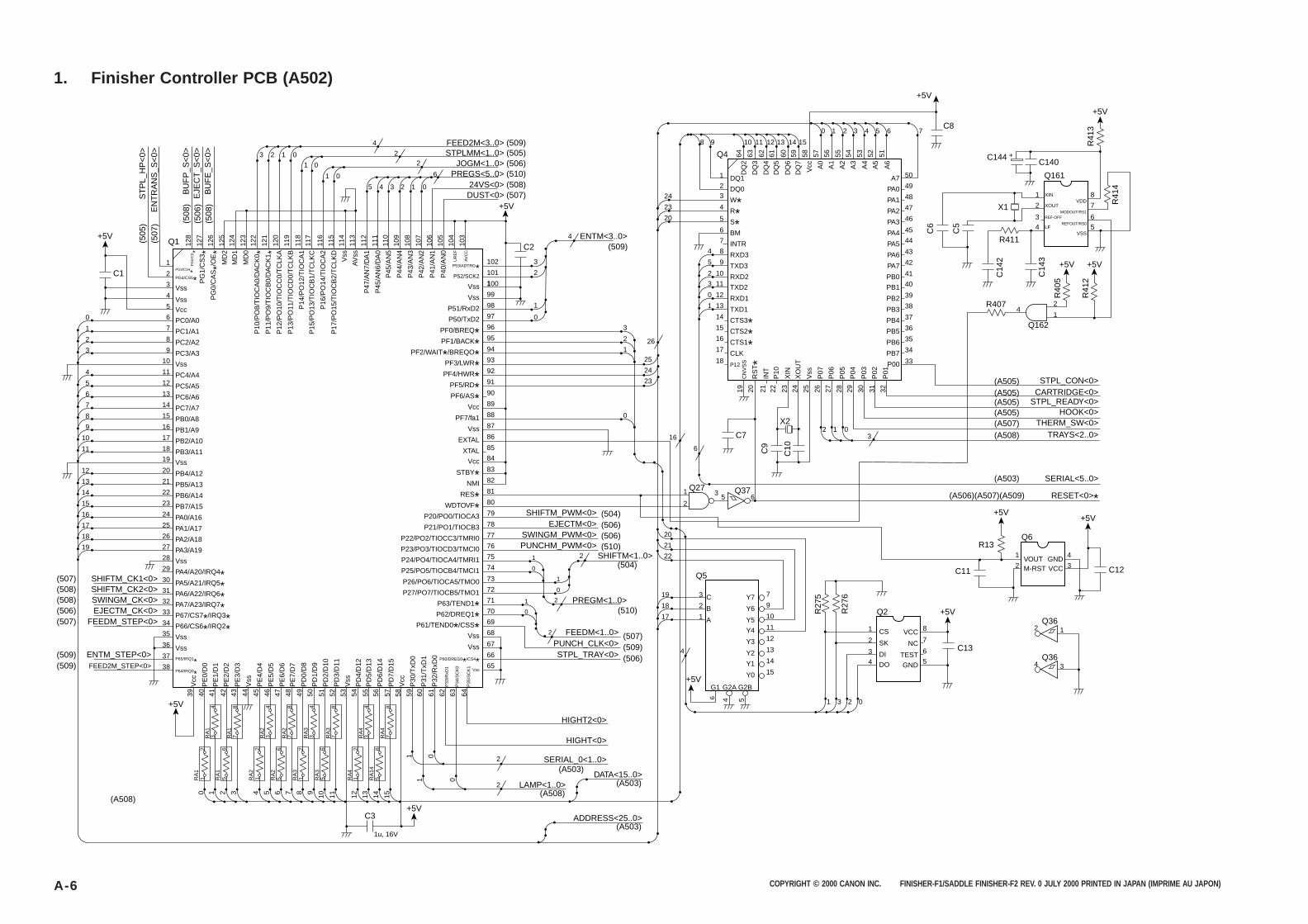
COPYRIGHT © 2000 CANON INC. FINISHER-F1/SADDLE FINISHER-F2 REV. 0 JULY 2000 PRINTED IN JAPAN (IMPRIME AU JAPON)A-6
1. Finisher Controller PCB (A502)
1PG3/CS4
*2PG4/CS5*3
128
PG
0/C
D*
127
ST
PL_
HP
<0>
BU
FP
_S<
0>E
JEC
T_S
<0>
BU
FE
_S<
0>
(508
)(5
06)
(508
)
(505
)(5
07)
EN
TR
AN
S_S
<0>
PG
1/C
S3 *
126
PG
0/C
AS*/O
E*
125
MD
212
4M
D1
123
122
MD
0
P10
/PO
8/T
IOC
A0/
DA
CK
0 *
114
Vss
113
AV
ss
4
5
0
3
4
22
+5V
C2ENTM<3..0>
(509)
FEED2M<3..0> (509)STPLMM<1..0> (505)
JOGM<1..0> (506)PREGS<5..0> (510)
24VS<0> (508)DUST<0> (507)
6
121
P11
/PO
9/T
IOC
B0/
DA
CK
1 *
2
120
P12
/PO
10/T
IOC
C0/
TC
LKA
1
119
P13
/PO
11/T
IOC
D0/
TC
LKB
0
118
P14
/PO
12/T
IOC
A1
1
117
116
P15
/PO
13/T
IOC
B1/
TC
LKC
0
P16
/PO
14/T
IOC
A2
115
P17
/PO
15/T
IOC
B2/
TC
LKD
112
P47
/AN
7/D
A1
111
P45
/AN
6/D
A0
110
P45
/AN
510
9P
44/A
N4
108
P43
/AN
310
7P
42/A
N2
106
P41
/AN
110
5P
40/A
N0
104
UR
EF
103
AV
CC
1
5 4 3 2 1 0
0
VccVss
Vss
6 PC0/A01 7 PC1/A12 8 PC2/A23
19 Y7
Y6
Y5
C
STPL_CON<0>(A505)CARTRIDGE<0>(A505)
STPL_READY<0>(A505)HOOK<0>(A505)
THERM_SW<0>(A507)TRAYS<2..0>(A508)
SERIAL<5..0>(A503)
RESET<0>*(A506)(A507)(A509)
B
A
CS
VOUTM-RST
GNDVCC
SK
DI
DO
1
2
1
2
2 1
4
3
3
4
VCC
NC
TEST
GND
8
7
6
5
1 3 2 0
Y4
Y3
Y2
Y1
Y0
4
G1+5V
+5V
+5V
+5V
+5V
G2A G2B
9
10
11
12
13
14
15
4 56
7
18
17
3
Q5
Q2
R13Q6
Q36
4 3Q36
C12
C3
1u, 16V
2
1
9 PC3/A3
4 11 PC4/A45 12 PC5/A56 13 PC6/A67 14 PC7/A78 15 PB0/A89 16 PB1/A9
10 17 PB2/A1011 18 PB3/A11
12 20 PB4/A1213 21 PB5/A1314 22 PB6/A1415 23 PB7/A1516 24 PA0/A1617 25 PA1/A1718 26 PA2/A1819 27 PA3/A19
10 Vss
19 Vss
DQ1
W*R*S*BM
INTR
RXD3
TXD3
RXD2
RXD1
TXD1
CTS3*CTS2*CTS1*CLK
P12
DQ0
TXD2
28 Vss29 PA4/A20/IRQ4*30SHIFTM_CK1<0>
SHIFTM_CK2<0>
EJECTM_CK<0>FEEDM_STEP<0>
ENTM_STEP<0>FEED2M_STEP<0>
SWINGM_CK<0>
(507)(508)
(506)(507)
(509)(509)
(A508)
(508)
PA5/A21/IRQ5*31 PA6/A22/IRQ6*32 PA7/A23/IRQ7*33 P67/CS7*/IRQ3*34 P66/CS6*/IRQ2*
37 P65/IRQ1*38
+5V
P64/IRQ0*
35 Vss36 Vss
P53/ADTRG*102
4
P52/SCK2 101
Vss 1100
Vss 99
P51/RxD2 98 1
0
2
3
2
1
24
23
20
4 8
7
6
5
4
32
1
Q4
5
1098
9
2 10
3 11
0 12
1 13
14
15
16
17
18
1
0
1
0
2
2
1
0
0
3
222
21
20
25
26
16
6
1 35 6
Q27
C7
C13
X2
C9
C10
R27
5
R27
6
Q37
C11
2
24
23
P50/TxD2 97
A7
+5V
C8
C140
+5V
+5V
+5V
C144
Q161
Q162
X1
R407
R411
C6
C5
C14
2
C14
3
R40
5
R41
2
R41
4
R41
3
+
41
XIN
XOUT
REF-OFF
LF
VDD
MODOUT/RS1
REFOUT/RS0
VSS
1
2
34
8
7
65
2
50
49
48
47
46
45
44
43
42
41
40
39
38
37
36
35
34
33
PA1
PA2
PA3
PA4
PA5
PA6
PA7
PB0
PB2
PB3
PB4
PB5
PB6
PB7
P00
PA0
PB1
CN
VS
S
RS
T*
INT
21
P10
22
XIN
23
XO
UT
24
Vss
25
P07
262019
PF0/BREQ*96
PF1/BACK*95
PF2/WAIT*/BREQO*94
PF4/HWR*92
PF5/RD*91
PF6/AS*90
Vcc 89
PF7/fa1 88
Vss 87
EXTAL 86
XTAL 85
STBY*83
NMI 82
RES*81
WDTOVF*80
P20/PO0/TIOCA3 79 (504)SHIFTM_PWM<0>
(506)STPL_TRAY<0>(509)PUNCH_CLK<0>(507)FEEDM<1..0>
(506)EJECTM<0>(506)SWINGM_PWM<0>(510)
(504)
(510)
PUNCHM_PWM<0>SHIFTM<1..0>
PREGM<1..0>
P21/PO1/TIOCB3 78
P22/PO2/TIOCC3/TMRI0 77
P23/PO3/TIOCD3/TMCI0 76
PF3/LWR*93
Vcc 84
P24/PO4/TIOCA4/TMRI1 75
P25/PO5/TIOCB4/TMCI1 74
P26/PO6/TIOCA5/TMO0 73
P27/PO7/TIOCB5/TMO1 72
P63/TEND1*71
P62/DREQ1*70
P61/TEND0*/CSS*69
P60/DREG0*/CS4*66
Vss
2
HIGHT2<0>
HIGHT<0>
SERIAL_0<1..0>
LAMP<1..0>
(A503)
(A508)
DATA<15..0>(A503)
ADDRESS<25..0>(A503)
2
65
Vss 68
Vss 67
2R
A1
10
39V
cc
PE
0/D
0
PE
1/D
1
PE
2/D
2
PE
3/D
3
Vss
PE
4/D
4
PE
5/D
5
PE
6/D
6
PE
7/D
7
PD
0/D
8
PD
1/D
9
PD
2/D
10
PD
3/D
11
Vss
PD
4/D
12
PD
5/D
13
PD
6/D
14
PD
7/D
15
Vcc
P30
/TxD
0
P31
/TxD
1
P32
/RxD
0
P33
/RxD
1
P34
/SC
K0
P35
/SC
K1
40 41 42 43 44 45 46 47 48 49 50 51 52 53 54 55 56 57 58 591 0
1 0
60 61 62 63 64
6R
A1
52
2R
A2
14
6R
A2
56
2R
A3
18
6R
A3
510
2R
A4
112
6R
A14
514 15
8R
A4
RA
4
RA
3
RA
3
RA
2
RA
2
RA
1
RA
1
7
118
7
94
3
78
7
54
3
38
7
14
3
134
3
2
P06
27
1
P05
P04
P03
P02
P01
64
11
63
12
62
13
61
14
60
15
59
0
5758
1
56
2
55
3
54
4
53
5
52
6 7
51
DQ
2
DQ
3
DQ
4
DQ
5
DQ
6
DQ
7
Vcc A0
A1
A2
A3
A4
A5
A6
28 29 30 31 32
03
+5V
C1
Q1
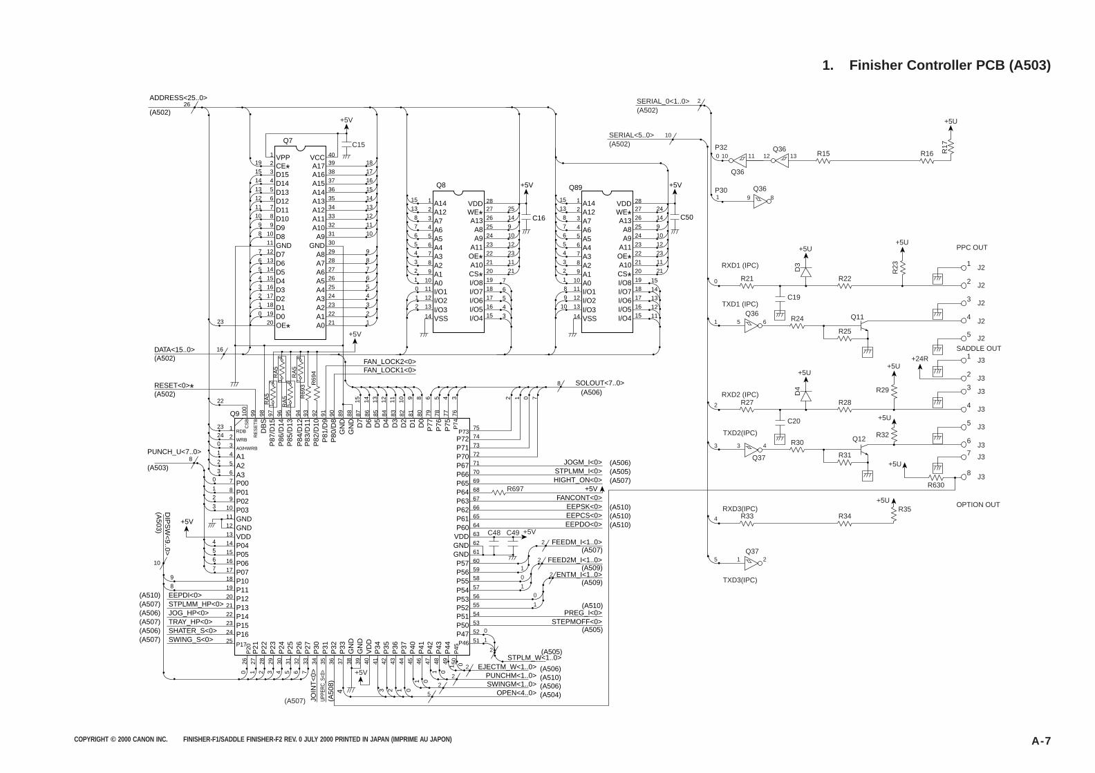
COPYRIGHT © 2000 CANON INC. FINISHER-F1/SADDLE FINISHER-F2 REV. 0 JULY 2000 PRINTED IN JAPAN (IMPRIME AU JAPON) A-7
1. Finisher Controller PCB (A503)
15
19
26
3 D15
2 CE*1 VPP
Q7
ADDRESS<25..0>
(A502)
14 4 D1413 5 D1312 6 D1211 7 D1110 8 D10
9 9 D98 10 D8
11 GND7 12 D76 13 D65 14 D54 15 D43 16 D32 17 D21 18 D10 19 D0
20 21 1
22 2
23 3
75P73
74P7273P7172P7071 JOGM_I<0> (A506)
SOLOUT<7..0>
FAN_LOCK2<0>FAN_LOCK1<0>
8
(A506)
P6770 STPLMM_I<0> (A505)P6669 HIGHT_ON<0> (A507)P6568 +5VP6467 FANCONT<0>P6366 EEPSK<0> (A510)P6265 EEPCS<0> (A510)P6164 EEPDO<0>
FEEDM_I<1..0>
(A510)
(A507)
PREG_I<0>(A510)
FEED2M_I<1..0>(A509)
ENTM_I<1..0>(A509)
P60
P57P56P55
63VDD
54P51STEPMOFF<0>
(A505)
STPLM_W<1..0>EJECTM_W<1..0>
(A505)
(A506)PUNCHM<1..0> (A510)SWINGM<1..0> (A506)
OPEN<4..0> (A504)
53P5052P4751P46
62
59
58
P54 57
P53 56
P52 55
GND61
60GND
24 4
25 5
26 6
27 7
28 8
29 9
30
31 10
32 11
33 12
34 13
35 14
36 15
37 16
38 17
3940
18
OE*23
16
22
23RDB1
Q9
PUNCH_U<7..0>
RESET<0>*(A502)
DATA<15..0>(A502)
(A503)
24WRB
RA
51 5
2 6
97P
87/D
15
RA
5
RA
5
95P
85/D
13
34
96P
86/D
14
RA
57
894
P84
/D12
R69
393
P83
/D11
R69
492
P82
/D10
91P
81/D
990
P80
/D8
89G
ND
88G
ND
8715 14 13 12 11 10 9 8 6 5 4 3 2 1 0 7
D7
86D
685
D5
84D
483
D3
82D
281
D1
80D
079
P77
78P
7677
P75
76P
74
98D
BS
99R
ES
ET
B
100
CS
B
20
A0/HWRB31
A142
A253
A360
P007
8
1P018
2P029
3
+5V
DIP
SW
<9..0>
(A503)
P0310
4P0414
5P0515
6P0616
7P0717
8P1119
9
10
76P
25P
26P
27P
30JO
INT
<0>
P31
UPPE
RC_S
<0>
P32
(A50
8)
P33
41P
3442
34 2 1 0
1 0
P35
43P
3644
P37
45P
4046
P41
147
P42
048
P43
149 050
P44
P45GN
DG
ND
4035 36 37 38 393431 32 33302926 27 28
VD
D
5P
244
P23
3P
222
P21
1P
200
P1018
VDD13GND12GND11
P1725SWING_S<0>(A507)
P1624SHATER_S<0>(A506)P1523TRAY_HP<0>(A507)P1422JOG_HP<0>(A506)P1321STPLMM_HP<0>(A507)P1220EEPDI<0>(A510)
A16A17
VCC
A15A14A13A12A11A10
A9GND
A8A7A6A5A4A3A2A1A0
213 A12
115
Q8
A14
38 A747 A656 A565 A474 A383 A292 A1
101 A0
1 12 I/O2I/O3VSS
2
0 11 I/O1
13
14
18
20 21
21 11
22 23
23 12
24 10
25 9
26 14
2728
25
C16
+5V
A13WE*VDD
A8A9
A11OE*A10CS*I/O7
19 7
617I/O6 516I/O5 415I/O4 3
I/O8
213 A12
115
Q89
A14
38 A747 A656 A565 A474 A383 A292 A1
101 A0
9 12 I/O2I/O3VSS
10
8 11 I/O1
13
14
18
20 21
21 11
22 23
23 12
24 10
25 9
26 14
2728
24
C50
+5V
A13WE*VDD
A8A9
A11OE*A10CS*I/O7
19 15
1417I/O6 1316I/O5 1215I/O4 11
I/O8
(A507)
+5V
J2
PPC OUT
SADDLE OUT
1
J22
J2
J2
3
J2
+24R
5
J31
J32
4
P32
P30
100
1
2
10
11
Q36
9 8
Q36
12 13 R16
+5U
R17
R15Q36
SERIAL_0<1..0>
SERIAL<5..0>(A502)
(A502)
R22
+5U+5U
R21
TXD1 (IPC)
RXD1 (IPC)
R23D3
C19
Q11
R25
R24
0
1 5 6Q36
J3
OPTION OUT
3
J34
J3
J3
5
J3+5U
J38
6
R28
R32
R29
R35
+5U+5U
R27
TXD2(IPC)
RXD2 (IPC)
+5U
D4
C20
Q12
R31
R30
2
R34R33RXD3(IPC)
TXD3(IPC)
4
3 3 4
5 1 2Q37
Q37
R630
+5U
+5V
+5V
C15
R697
+5VC48 C492
2
2
2
2
2
2
5
1
0
0
1
1
0
1
7
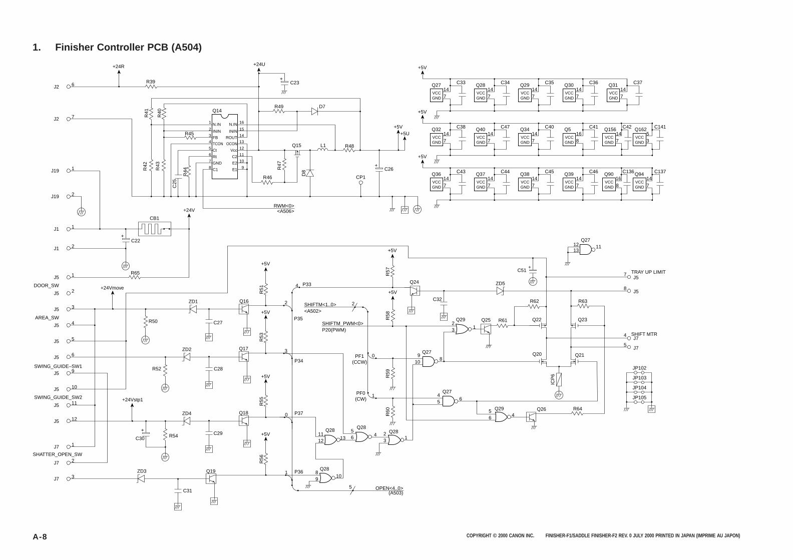
COPYRIGHT © 2000 CANON INC. FINISHER-F1/SADDLE FINISHER-F2 REV. 0 JULY 2000 PRINTED IN JAPAN (IMPRIME AU JAPON)A-8
1. Finisher Controller PCB (A504)
+
+
6
R41
R42
R44
C25
R43
R40
R39
R45
1 16N.IN N.IN2 15ININ ININ3 14FB ROUT4 13TCON OCON5 12Ct Vcc6 11Rt C27 10GND E28 9C1 E1
Q14
+24R +24U
R49
L1
D7
C26
Q15 R48
CP1R46
RWM<0><A506>
R47
D8
C23J2
7
1J19
2J19
1J1
2C22
R65
+24Vmove
+24V
CB1
J1
1J5
2J5
DOOR_SW
AREA_SW
SWING_GUIDE–SW1
SWING_GUIDE_SW2
SHATTER_OPEN_SW
3J5
4J5
5J5
6J5
9J5
10J5
11J5
12J5
1J7
2J7
3J7
+
+5V
+5V
+5V
+
+5V
JP102
J7
Q26Q29
Q27
Q27
4
J75
56 4
45
6
90
2
1
108
J58
J5TRAY UP LIMIT
SHIFT MTR
7
JP103
JP104
JP105
+
+5V+5U
+5V
VCCGND
Q27
714
C33
VCCGND
Q28
714
C34
VCCGND
Q29
714
C35
VCCGND
Q30
714
C36
VCCGND
Q31
714
C37
+5V
VCCGND
Q32
714
C38
VCCGND
Q40
714
C47
VCCGND
Q34
714
C40
VCCGND
Q5
816
C41
VCCGND
Q162
35
C141
VCCGND
Q156
714
C42
+5V
VCCGND
Q36
714
C43
VCCGND
Q37
714
C44
VCCGND
Q38
714
C45
VCCGND
Q39
Q27
714
12
C51
1113
C46
VCCGND
Q94
714
C137
VCCGND
R63
R64
R62
Q22 Q23
Q20 Q21
ICP
6
R61
ZD5
R59
R58
R57
R60
Q282
PF0(CW)
PF1(CCW)
3 1
Q29 Q25
Q24P33
Q16
R51
R53
+5V
R55
+5V
Q19
Q18
Q17
ZD3
ZD4
+24Vstp1
C31
C30 R54
ZD2
ZD1
R52
R50
C29
P37
P36
P34
0
1
5 OPEN<4..0>(A503)
C28
C27
R56
P35
2
3
4
SHIFTM<1..0><A502>
SHIFTM_PWM<0>P20(PWM)
2
C32
3 1
Q2856 4
Q281112 13
Q2889
10
Q90
816
C136
J2
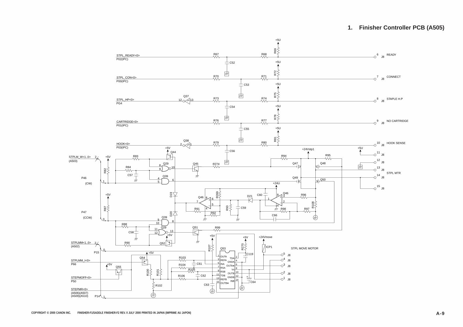
COPYRIGHT © 2000 CANON INC. FINISHER-F1/SADDLE FINISHER-F2 REV. 0 JULY 2000 PRINTED IN JAPAN (IMPRIME AU JAPON) A-9
1. Finisher Controller PCB (A505)
+5U
45
6
89
10
R69
Q29 Q45
Q44
Q39
C52
STPL_READY<0>P02(IPC)
12 13Q37
2 1Q38
6J8
READYR67 R68
+5U
R72
C53
STPL_CON<0>P00(IPC)
7J8
CONNECTR70 R71
+5U
R75
C54
STPL_HP<0>PG4
8J8
STAPLE H.PR73 R74
+5U
R78
C55
CARTRIDGE<0>P01(IPC)
9J8
NO CARTRIDGER76
R95
R77
+5U
+5U+24Vstp1
R81
C56
HOOK<0>P03(IPC)
10J8
11J8
12J8
13J8
14J8
15J8
HOOK SENSE
STPL MTR
STPL MOVE MOTOR
R79
+24U
R80
R94
Q47
Q49Q50
8
4
13
2
+
–
8
4
7
Q46Q46
6
5
+
–
Q48
C60D21
C66
C59
C58
R96
R97R98R91
+5V
+5V
+5V
R102
D19
D20
R10
8
R93
R26
9R92
R83
+5V
+5V
R84
1
0
2
P46
(CW)
P47
STPLMM<1..0>(A502)
STPLMM_I<0>P66
STEPMOFF<0>P50
STEPMR<0>(A506)(A507)(A509)(A510)
(CCW)
STPLM_W<1..0>(A503)
C57
R82
+5V
R87
R99
910
8
1112
13Q29
Q52
Q54
Q55
Q51
P14
Q39
R88
R90
R10
0
R10
1
C61
C62
C63C64
R103
R104
R105
1
3
5
7
9
11
13
15
2
4
6
8
10
12
14
OUTA
REFA
INA
RSA
RSB
TDB
REFB
TDA
GNDA
OUTA*Vs
OUTB
GNDB
INBOUTB*
R106
+5V
R10
7
+ 1 J8
2 J8
3 J8
5 J84 J8
+5V +24Vmove
R27
0
C119
Q53 ICP12
0
1
P15
R274
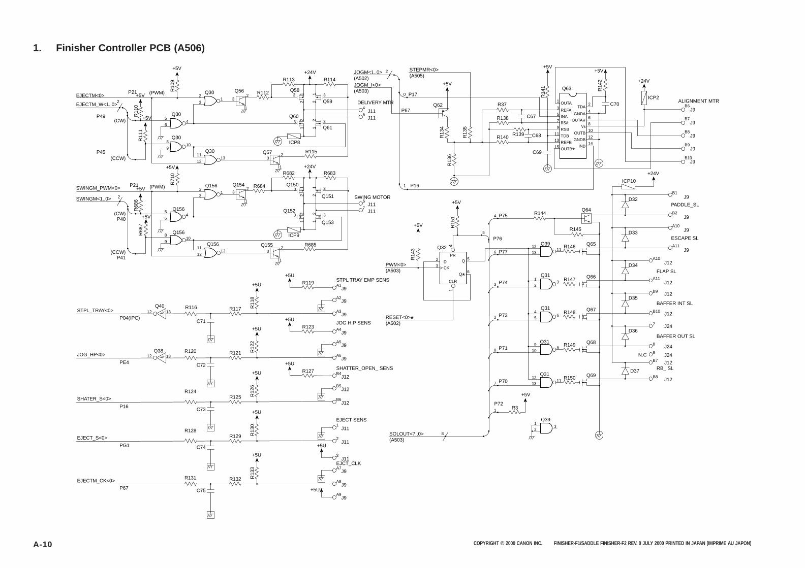
COPYRIGHT © 2000 CANON INC. FINISHER-F1/SADDLE FINISHER-F2 REV. 0 JULY 2000 PRINTED IN JAPAN (IMPRIME AU JAPON)A-10
1. Finisher Controller PCB (A506)
+5V
+5V
+5V
+5V
+5V
+5VQ30
1 3
3
2
1
3
3
3
2
1
32
1
32
1
2
3
Q304
5
6
Q3013
11
12
Q156
Q156
12
3
45
6
Q15610
8
9 Q156
+5U
+5U
1311
12
Q3010
8
9
Q56
EJECTM_W<1..0>
SWINGM_PWM<0>
SWINGM<1..0>
P49
P21 (PWM)
P21
R11
0
R10
9R
710
R11
1R
686
R68
7
(CW)
(CW)P40
(CCW)P41
(CCW)
2
(PWM)
2
P45
EJECTM<0>
Q57
Q154
Q155
R113
Q583
21
Q60
ICP8
Q593
3
J11
JOGM<1..0>(A502)JOGM_I<0>(A503)
STEPMR<0>(A505)
4
P17
+5V
+5V+5V
+24V
P67
DELIVERY MTR
2
0
J115
J116
SWING MOTOR
J117
J9A1STPL TRAY EMP SENS
JOG H.P SENS
SHATTER_OPEN_ SENS
SOLOUT<7..0>(A503)
RESET<0>*(A502)
PWM<0>(A503)
8
EJECT SENS
EJCT_CLK
J9A2
J9A3
Q6112
21
12
R112
R114
R115
R682
+24V
+24V
ICP9
Q150
2
Q152
Q151
3
Q1531
21
12
R119
R117R11612 13
13
Q40STPL_TRAY<0>
P04(IPC)
PE4
P16
PG1
P67
R11
8
R684
R685
R683
12OUTA
J9B6
J9B7
J9B8
J9B9
J9B10
TDA34REFA
GNDA56INA
OUTA*78RSA
Vs9
C70
10RSBOUTB11
12TDBGNDB13
14REFBINB15 OUTB*
Q63
ICP2ALIGNMENT MTR
R14
2
R14
1
R13
4
R15
14
R14
3
R13
6
R13
5
R37
R140
R138
R139 C68
C67
C69
Q62
C71
C72
C73
C74
C75
+5U
+5UJ9
A4
J9A5
J9A6
R123
R121R12012
Q38JOG_HP<0>
R12
2
+5U
+5UJ12
B4
J12B5
J12B6
R127
R125R124
SHATER_S<0>
R12
6
+5U
J111
J112R129
R128
EJECT_S<0>
R13
0
+5U
+5U
+5UJ11
3
J9A7
J9A8
J9A9
R132R131EJECTM_CK<0>
R13
3
ICP10
+24V
B1J9
PADDLE_SL
ESCAPE SL
FLAP SL
BAFFER INT SL
BAFFER OUT SL
RB_ SL
A10J9
A11J9
B2J9
D32
D33
R144Q64
Q65R146
Q66R147
Q67R148
Q68R149
Q69R150
R145
Q39
A10J12
A11J12
J12
J12
J12
J12
J24
J24
D34
Q31
B9
B10
D35
Q31
7
8
J24N.C 9
D36
Q31
Q31
B7
B8D37
+5V
R3
3
11
8
1
1
7
2
12
13
9
10
6
3
11
4
5
1
2
12
13
P72
P70
0 P71
2 P73
3 P74
6
2
3
P77
4
Q32
+5V
+5V
PR
CLR
P75
P76
5
5
P161
D
CK
1
Q
Q*6
Q39
1 3
2
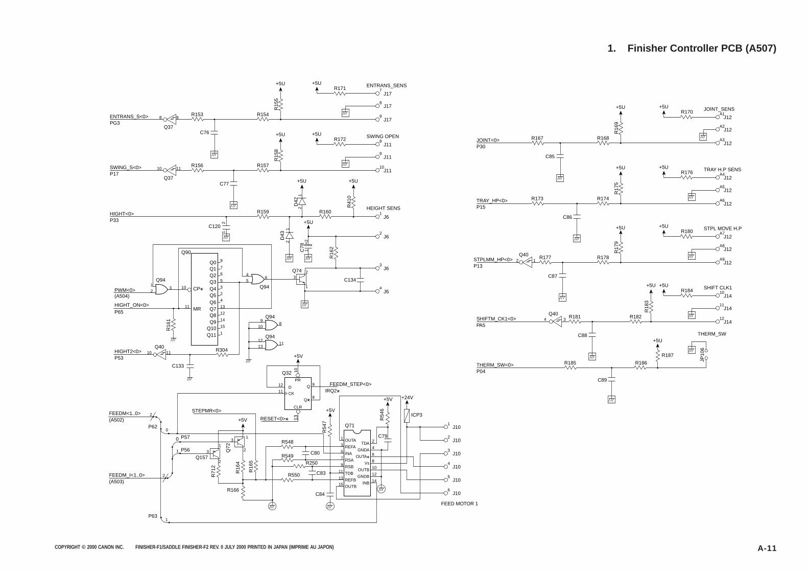
COPYRIGHT © 2000 CANON INC. FINISHER-F1/SADDLE FINISHER-F2 REV. 0 JULY 2000 PRINTED IN JAPAN (IMPRIME AU JAPON) A-11
1. Finisher Controller PCB (A507)
+5U
Q94
Q743
4
Q0Q1Q2Q3Q4Q5Q6Q7Q8Q9
Q10Q11
5
26
9
PWM<0>(A504)
HIGHT_ON<0>
HIGHT2<0>
P65
P53
FEEDM<1..0>(A502)
FEEDM_I<1..0>(A503)
7
6
5
3
2
Q94
CP*
MR
4
13
12
14
15
1
9
108
1
+5V
Q94
12
1311
1
210
11
3
Q94
C76
R153 R154
R171 7J17
9J17
8J17
ENTRANS_SENS
R15
5
8 9ENTRANS_S<0>PG3
Q37
+5U
+5U
C85
R167 R168
R170 A1J12
A3J12
A2J12
JOINT_SENS
R16
9
JOINT<0>P30
2 1Q40
+5U
+5U
+5U
C86
R173 R174
R176 A4J12
A6J12
A5J12
TRAY H.P SENS
R17
5
TRAY_HP<0>P15
+5U
C87
R177
Q40
R178
R180 A7J12
A9J12
A8J12
STPL MOVE H.P
R17
9
STPLMM_HP<0>P13
+5U
C88
4 3R181 R182
R184 10J14
12J14
JP10
6
11J14
SHIFT CLK1
R18
3
SHIFTM_CK1<0>PA5
+5U+5U
C89
R185 R186
R187
THERM_SW
THERM_SW<0>P04
+5U
+5U
C77
C120
Q90
C133
R156 R157
R172 8J11
10J11
9J11
SWING OPEN
HEIGHT SENS
R15
8
+5U
R41
0
R16
2
+5U
D42
2
1+
2
1
D43
2
1
1
2
R16
1
C78
10 11SWING_S<0>P17
R159
+5U
C134
R160 1J6
2J6
3J6
4J6
HIGHT<0>P33
Q37
+5U
10 11Q40
10
12
11
Q32PR
CLR
9 FEEDM_STEP<0>IRQ2*
D
CK
13
Q
Q*8
+5V
R548
R550 C83
C84
2TDA4
1J10
2J10
3J10
4J10
5J10
6J10
FEED MOTOR 1
GNDA6OUTA* 8Vs10OUTB12GNDB14
1
Q71
3
5
7
9
11
13
15 INB
OUTA
OUTB
REFA
INA
RSA
RSB
TDB
REFB
R549R250
C80
C79
Q157
R166
31
2
31
2
R71
2
Q72
R16
4
R16
5
2
0
0
1
1
2
P62
P63
P57
STEPMR<0>
RESET<0>*
P56
+5V
+5V +24V
R54
7
R54
6
ICP3
R304
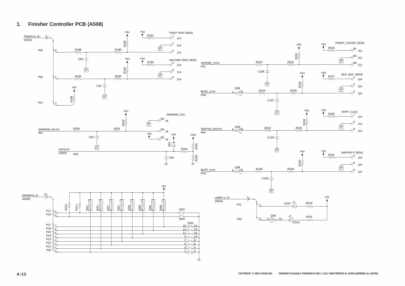
COPYRIGHT © 2000 CANON INC. FINISHER-F1/SADDLE FINISHER-F2 REV. 0 JULY 2000 PRINTED IN JAPAN (IMPRIME AU JAPON)A-12
1. Finisher Controller PCB (A508)
+5U
C106
B3J12
B2J12
B1
+5UR223
R220
R22
2
R221
J12
FRONT_COVER_SENS
UPPERC_S<0>P31
+5U
C90
3J14
2J14
1FIRST TRAY SENS
SECOND TRAY SENS
+5UR191
R188
R19
0
R189
J14
+5U
C91
2
1
0
3
6J14
5J14
4
+5UR195
R192
R19
4
R193
J14
+5U
C93
C94
B4J9
B3J9
B5
SWINGM_CLK
+5U
R200
R20
2
+5V
D64
+24U
R20
5R
206
R201
J9
TRAYS<2..0>
SWINGM_CK<0>PA7
24VS<0>(A502) AN1
DIPSW<9..0>(A503)
P05
P06
P07
+5U
C107
3J24
2J24
1
+5UR227
R224
R22
6
R225
J24
BUFE_S<0>PG0
+5U
C109
C108
9J14
8J14
7
+5UR235
R232
R23
4
R233
J14
SHIFT_CLK2
BAFFER P SENS
BUF_ENT_SENS
SHIFTM_CK2<0>PA6
+5U
6J24
5J24
4
+5UR231
R228
R23
0
R229
J24
BUFP_S<0>PG2
+5V
LED2
LED1
LAMP<1..0>(A503)
4 3Q38
8 9Q38
6 5Q38
R240
R24111 100
1
2
P31
P33Q38
+5V
R19
8
R204
210P20431P21652P22873P231094P2412115P2514136P2616157P27
9P10
SW1
SW3
+5V
RA
82
1RA
84
3RA
86
5RA
88
7RA
72
1RA
74
3RA
76
5RA
78
7R21
1
R21
0
SW2
8P11
10
(A502)
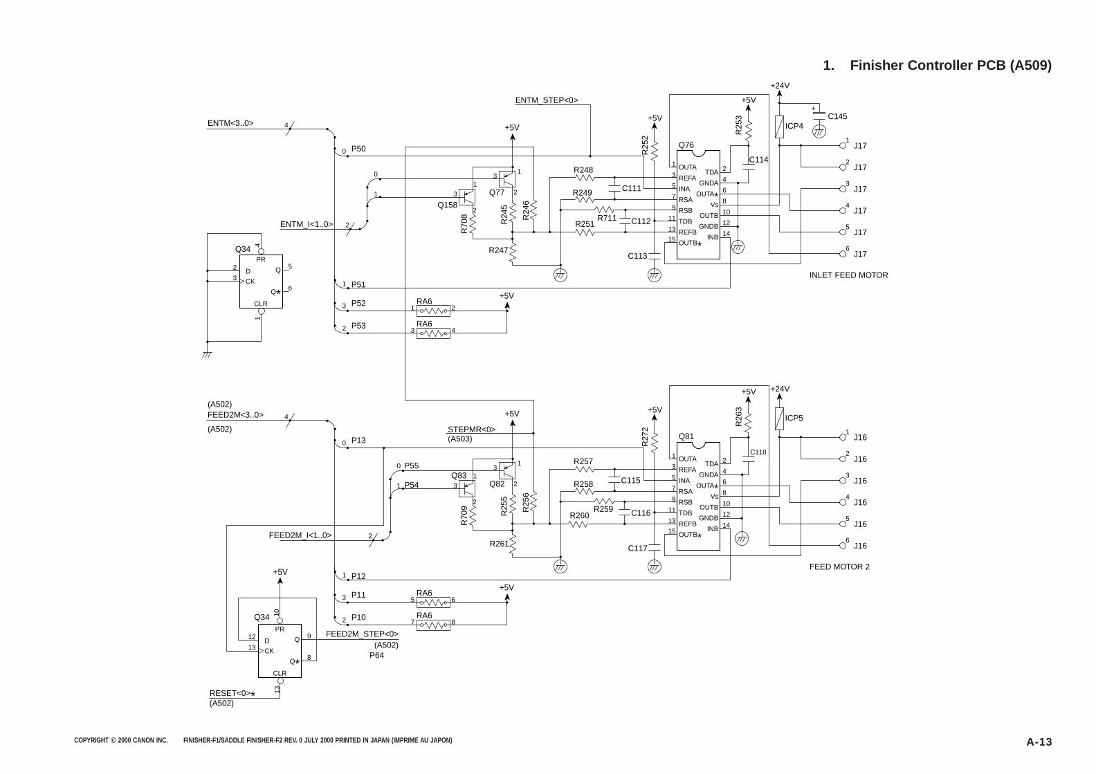
COPYRIGHT © 2000 CANON INC. FINISHER-F1/SADDLE FINISHER-F2 REV. 0 JULY 2000 PRINTED IN JAPAN (IMPRIME AU JAPON) A-13
1. Finisher Controller PCB (A509)
ENTM<3..0>
ENTM_I<1..0>
4
2
3
Q34PR
CLR
D5
6CK
1
Q
Q*
+5V
+5V
R248
R251 C112
C113
2TDA4
1
+
J17
2J17
3J17
4J17
5J17
6J17
GNDA6OUTA* 8Vs10OUTB12GNDB14
1
Q76
ENTM_STEP<0>
3
5
7
9
11
13
15 INB
OUTA
OUTB*
REFA
INA
RSA
RSB
TDB
REFB
R249
R711
C111
C114
Q158
R247
31
2
31
2
R70
8
Q77
R24
5
R24
6
2
0
1
0
1 2
3 4
RA6
4
P50
3
1
P52
P51
RA62 P53
+5V
+5V
+24V
R25
2
R25
3
ICP4C145
INLET FEED MOTOR
FEED2M<3..0>
FEED2M_I<1..0>
(A502)
(A502)
RESET<0>*(A502)
FEED2M_STEP<0>(A502)
P64
10
12
13
Q34PR
CLR
D9
8CK
13
Q
Q*
+5V
+5V
R257
R260 C116
C117
2TDA4
1J16
2J16
3J16
4J16
5J16
6J16
GNDA6OUTA* 8Vs10OUTB12GNDB14
1
Q81
3
5
7
9
11
13
15 INB
OUTA
OUTB*
REFA
INA
RSA
RSB
TDB
REFB
R258
R259
C115
C118
Q83
R261
31
2
31
2
R70
9
Q82
STEPMR<0>(A503)
R25
5
R25
62
0
1
0
5 6
7 8
RA6
4
P13
3
1
P11
P12+5V
RA62 P10
P55
P54
+5V
+5V +24V
R27
2
R26
3
ICP5
FEED MOTOR 2
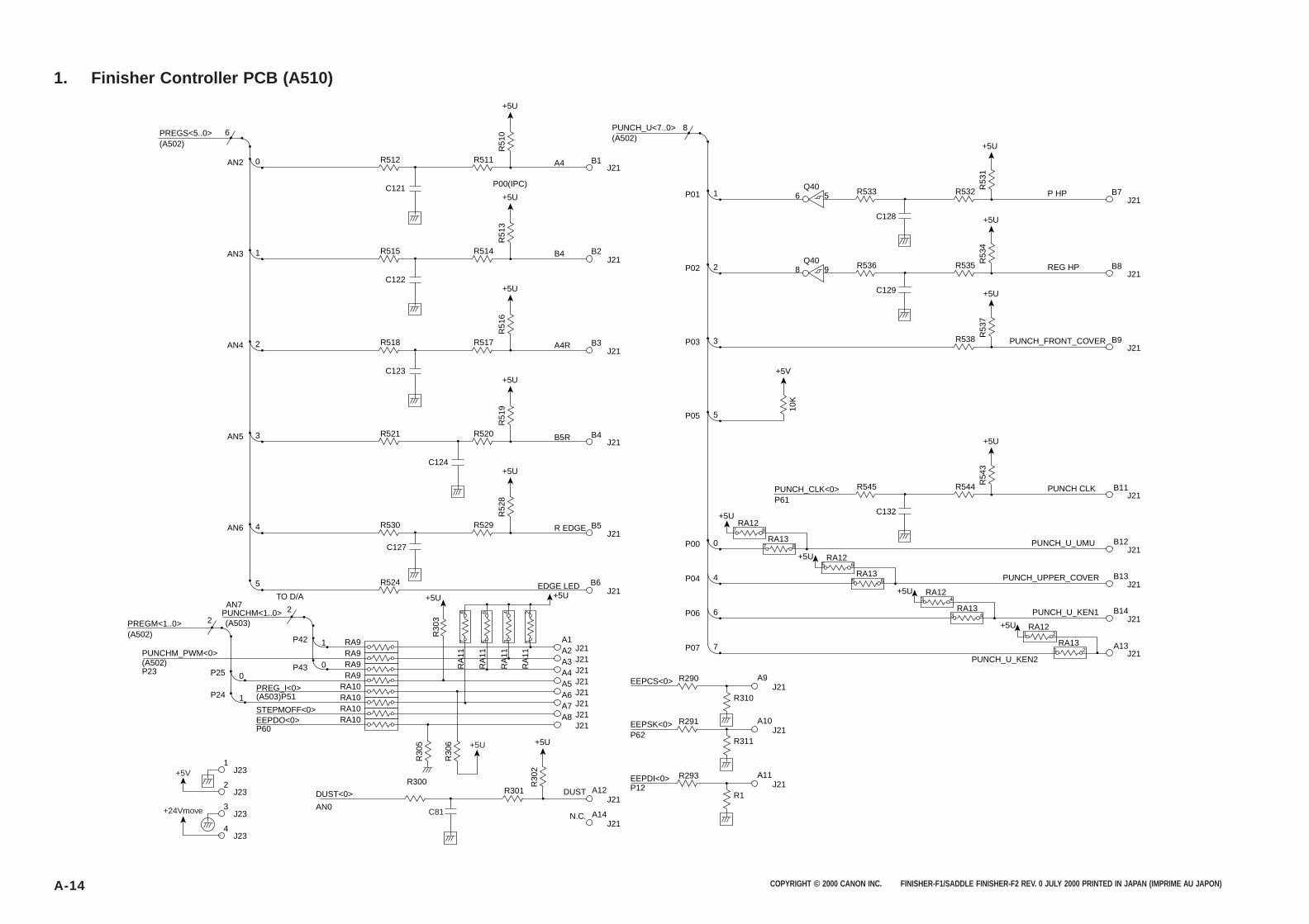
COPYRIGHT © 2000 CANON INC. FINISHER-F1/SADDLE FINISHER-F2 REV. 0 JULY 2000 PRINTED IN JAPAN (IMPRIME AU JAPON)A-14
1. Finisher Controller PCB (A510)
+5U
R51
0
R512 R511
5
1
0
6
C121
PREGS<5..0>(A502)
PREGM<1..0>
PREG_I<0>(A503)P51
EEPDO<0>STEPMOFF<0>
P60
(A502)(A503)
AN7TO D/A
PUNCHM_PWM<0>
PUNCHM<1..0>
(A502)P23
AN2
+5U
J21B7
B8
B9
P HPR533 R53
1
R5321
8
C128
P01+5U
P00(IPC)
J21
J21B1A4
B2B4
B3A4R
B4B5R
B5R EDGE
EDGE LED
PUNCH_U<7..0>(A502)
R51
3
R515 R5141
C122
AN3
+5U
J21
R51
6
R518 R5172
C123
AN4
+5U
J21
R51
9
R521 R520
+5U
J21A12DUST
J21A14N.C.
R30
2
R301R300
3
C124
AN5
+5U
+5U+5U
J21
R52
8
R30
5
J21EEPCS<0> A9R290
R310
J21EEPSK<0>P62
P12
A10R291
R311
J21EEPDI<0> A11R293
R1
R30
6
R530 R5294
C127
AN6
J21B6
J21A1
R524
21
43
65
87
RA
11
RA
11
RA
11
RA
11
RA9
87RA12
87RA13
+5U
P42
J21A2RA9
0J21
A3RA9P430
J21A4RA9P25
J21A5RA10
1J21
A6RA10P24
J21A7RA10
J21A8RA10
J23
DUST<0>
AN0
1
J232
R30
322
+5U
+5V
J233
J234
+24Vmove C81
6 5Q40
+5U
J21REG HPR536 R
534
R5352
C129
P02 8 9Q40
+5U
J21PUNCH_FRONT_COVER
R53
7
R5383P03
5P05
+5U
J21PUNCH CLKR545 R
543
R544
C132
J21PUNCH_U_UMU0P00
65RA12
65RA13
+5U
J21PUNCH_UPPER_COVER4P04
43RA12
RA1343
PUNCH_CLK<0>P61
+5U
J21PUNCH_U_KEN16P06
21RA12
21RA13
+5U
J21A13
B14
B13
B12
B11
PUNCH_U_KEN2
7P07
+5V
10K

COPYRIGHT © 2000 CANON INC. FINISHER-F1/SADDLE FINISHER-F2 REV. 0 JULY 2000 PRINTED IN JAPAN (IMPRIME AU JAPON) A-15
APPENDIX
2. Sensor PCB
6J400
5J400
4J400
3J400
2J400
1J400
PI19
PI9

COPYRIGHT © 2000 CANON INC. FINISHER-F1/SADDLE FINISHER-F2 REV. 0 JULY 2000 PRINTED IN JAPAN (IMPRIME AU JAPON)A-16
APPENDIX
3. Relay PCB 3
5 18J304 J302
4 17J304 J302
3 16J304 J302
2 15J304 J302
1 14J304 J302
13 J302
12 J302
11 11J305 J302
10 10J305 J302
9 9J305 J302
8 8J305 J302
7 7J305 J302
6 6J305 J302
5 5J305 J302
4 4J305 J302
3 3J305 J302
2 2J305 J302
1 1J305 J302
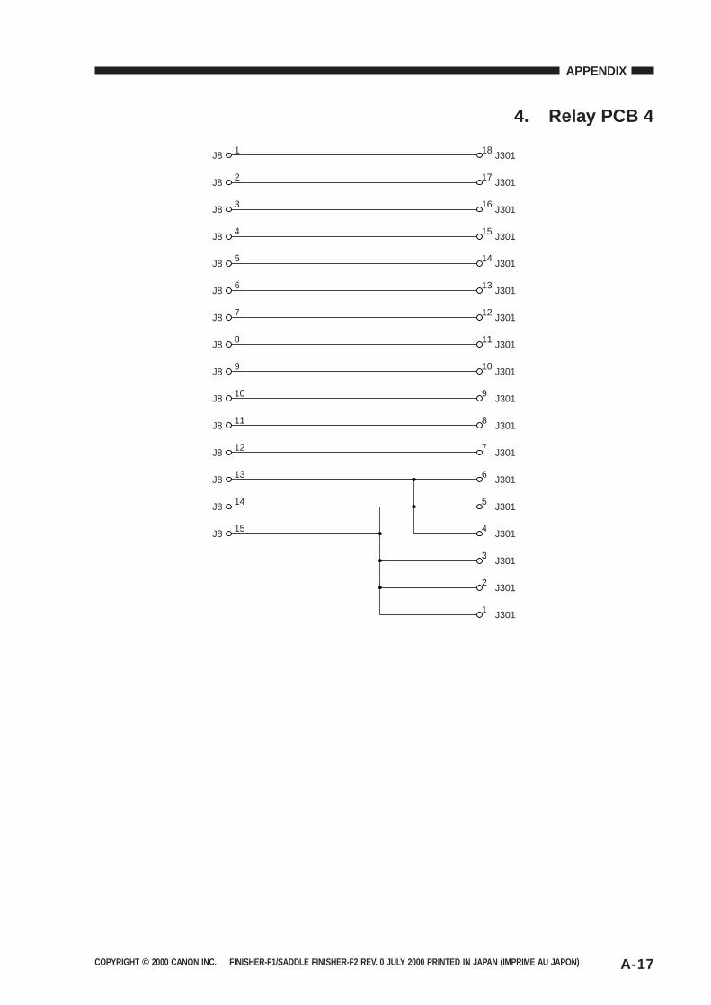
COPYRIGHT © 2000 CANON INC. FINISHER-F1/SADDLE FINISHER-F2 REV. 0 JULY 2000 PRINTED IN JAPAN (IMPRIME AU JAPON) A-17
APPENDIX
4. Relay PCB 4
1 18J8 J301
2 17J8 J301
3 16J8 J301
4 15J8 J301
5 14J8
6J8
7J8
J301
13 J301
12 J301
8 11J8 J301
9 10J8 J301
10 9J8 J301
11 8J8 J301
12 7J8 J301
13 6J8 J301
14 5J8 J301
15 4J8 J301
3 J301
2 J301
1 J301

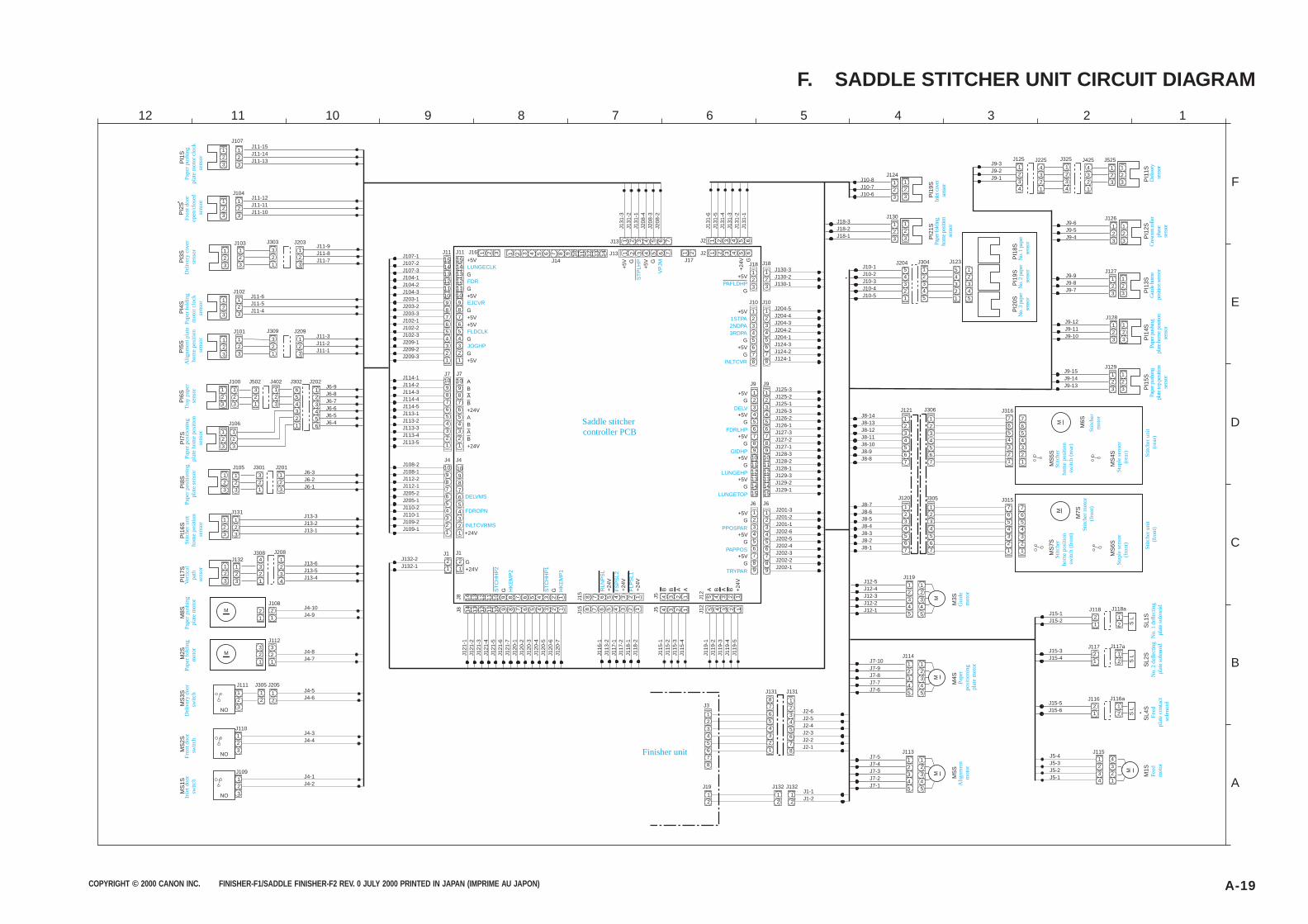
COPYRIGHT © 2000 CANON INC. FINISHER-F1/SADDLE FINISHER-F2 REV. 0 JULY 2000 PRINTED IN JAPAN (IMPRIME AU JAPON) A-19
F. SADDLE STITCHER UNIT CIRCUIT DIAGRAM
J102
J303
J11-15J11-14J11-13
J11-12J11-11J11-10
123
PI1
S 123
123
123
123
J6-9J6-8J6-7J6-6J6-5J6-4
123456
654321
J107
J104
123
123
J103321
J203
J309
123
321
J209
J11-9J11-8J11-7
123
123
J11-6J11-5J11-4
J101
123
123
J11-3J11-2J11-1
J100
123
123
J402
321
123
J502 J302 J202
123
123
J106
123
123
123
J105 J301 J201J6-3J6-2J6-1
J131J13-3J13-2J13-1
123
123
123
123
4321
1234
J132J308 J208
J13-6J13-5J13-4
M 21
21
J4-10J4-9
J108
M
J112
J4-8J4-7
321
321
J111 J305 J205J4-5J4-6
J110
123
123
12
12
J4-3J4-4
J109123
J4-1J4-2
J108-2J108-1J112-2J112-1J205-2J205-1J110-2J110-1J109-2J109-1
10987654321
10987654321
J4
J1
21
21
J132-2J132-1
10987654321
10987654321
J7
J11
J114-1J114-2J114-3J114-4J114-5J113-1J113-2J113-3J113-4J113-5
151413121110987654321
151413121110987654321
J107-1J107-2J107-3J104-1J104-2J104-3J203-1J203-2J203-3J102-1J102-2J102-3J209-1J209-2J209-3
14 13 12 11 10 9 8 7 6 5 4 3 2 1
14 13 12 11 10 9 8 7 6 5 4 3 2 1
J121
-1J1
21-2
J121
-3J1
21-4
J121
-5J1
21-6
J121
-7J1
20-1
J120
-2J1
20-3
J120
-4J1
20-5
J120
-6J1
20-7
8 7 6 5 4 3 2 1
J116
-1J1
13-2
J117
-1J1
17-2
J118
-1J1
18-2
8 7 6 5 4 3 2 1
J15
J8
J115
-1J1
15-2
J115
-3J1
15-4
4 3 2 1
4 3 2 1J5
J119
-1J1
19-2
J119
-3J1
19-4
J119
-5
5 4 3 2 1
5 4 3 2 1J12
12345678
12345678
J10J204-5J204-4J204-3J204-2J204-1J124-3J124-2J124-1
123
123
J18J130-3J130-2J130-1
J9
123456789
101112131415
123456789
101112131415
J125-3J125-2J125-1J126-3J126-2J126-1J127-3J127-2J127-1J128-3J128-2J128-1J129-3J129-2J129-1
J6
123456789
123456789
J201-3J201-2J201-1J202-6J202-5J202-4J202-3J202-2J202-1
J10-8J10-7J10-6
123
123
J124
J10-1J10-2J10-3J10-4J10-5
54321
12345
J204 J304
54321
12345
J123
J9-3J9-2J9-1
4321
123
123
J5251234
J325 J4254321
1234
J125 J225
J9-6J9-5J9-4
J9-9J9-8J9-7
123
123
123
123
J126
J127
J9-12J9-11J9-10
123
123
J128
J9-15J9-14J9-13
123
123
J129
J8-14J8-13J8-12J8-11J8-10J8-9J8-8
1234567
J121
1234567
J306
7654321
7654321
J8-7J8-6J8-5J8-4J8-3J8-2J8-1
1234567
J120
1234567
J305
7654321
7654321
J12-5J12-4J12-3J12-2J12-1
12345
J119
12
21
12345 J15-1
J15-2
12
21
J15-3J15-4
J118
J117
J118a
J117a
12
21
J15-5J15-6
J116 J116a
S L
S L
S L
1234
J5-4J5-3J5-2J5-1
J115
M
4321
12345
J7-10J7-9J7-8J7-7J7-6
J114
MM
M
12345
12345
J7-5J7-4J7-3J7-2J7-1
J113
12345
J131
12345678
J3
12345678
J131
87654321
J2-6J2-5J2-4J2-3J2-2J2-1
J132
12
J132
12
J19
12
J1-1J1-2
J131
-6J1
31-5
J131
-4J1
31-3
J131
-2J1
31-1
1 2 3 4 5 6
1 2 3 4 5 6
J2
1 21 2 3
J131
-3J1
31-2
J131
-1J2
08-4
J208
-3J2
08-2
1 2 3 4 5 6 7
1 2 3 4 5 6 7
J13
1 2 3 4 5 6 7 8 9 10 11 12 13 14
PI2
SP
I3S
PI4
SP
I5S
PI6
SP
I7S
PI8
SP
I16S
PI1
7SM
8SM
2SM
S1S
MS
2SM
S3S
M4S
M5S M1S
SL4
SS
L2S
SL1
S
M3S
MS
7SM
MS
5S
MS
6SM
S4S
M
M6S
M7S
PI1
5SP
I14S
PI1
3SP
I12S
PI1
1S
PI1
9S
J18-3J18-2J18-1
123
123
J130
PI2
1S
PI1
8SP
I19S
PI2
0S
J316
J315
321
NO
NO
NO
J4
J1
J7
J11 J16
J15
J8 J5 J12
J10
J18
J9
J6
J2J17
J13J14+5V
G
G+5V
G+5V+5V
G
G+5V
ABAB+24VABAB+24V
+24V
G G
+5V
G+5V
G
+24
V G
G+24V
+24
V
+24
V
+24
V
+5VG
+5VG
+5VG
+5VG
+5VG
+5VG
+5VG
+5VG
B B A A A B A B +24
V
+5V G
+5V G
+5V
G
Del
iver
y do
or
switc
hP
aper
fold
ing
mot
orP
aper
pus
hing
pl
ate
mot
orVe
rtic
al
path
se
nsor
Stit
cher
uni
t ho
me
posi
tion
sens
or
Pap
er p
ositi
onin
g pl
ate
sens
orP
aper
pos
ition
ing
plat
e ho
me
posi
tion
sens
or
Tra
y pa
per
sens
orA
lignm
ent p
late
ho
me
posi
tion
sens
or
Pap
er fo
ldin
g m
otor
clo
ck
sens
or
Del
iver
y co
ver
sens
orF
ront
doo
r op
en/c
lose
d se
nsor
Pap
er p
ushi
ng
plat
e m
otor
clo
ck
sens
or
Saddle stitcher controller PCB
Finisher unit
Alig
nmen
t m
otor
Gui
de
mot
or
Fee
d m
otor
Fee
d pl
ate
cont
act
sole
noid
No.
2 d
efle
ctin
g pl
ate
sole
noid
No.
1 d
efle
ctin
g pl
ate
sole
noid
Stit
cher
ho
me
posi
tion
switc
h (f
ront
)
Sta
ple
sens
or(f
ront
)
Stit
cher
mot
or
(fro
nt)
Stit
cher
uni
t (f
ront
)
Stit
cher
ho
me
posi
tion
switc
h (r
ear)
Sta
ple
sens
or(r
ear)
Stit
cher
mot
or
Stit
cher
uni
t (r
ear)
No.
3 p
aper
se
nsor
No.
2 p
aper
se
nsor
No.
1 p
aper
se
nsorPap
er fo
ldin
g ho
me
posi
tion
sens
or
Inle
t cov
er
sens
or
Pap
er p
ushi
ng
plat
e to
p po
sitio
n se
nsor
Pap
er p
ushi
ng
plat
e ho
me
posi
tion
sens
or
Gui
de h
ome
posi
tion
sens
orC
resc
ent r
olle
r ph
ase
sens
or
Del
iver
y se
nsor
Pap
er
posi
tioni
ng
plat
e m
otor
LUNGECLK
FDR
EJCVR
FLDCLK
JOGHP
DELVMS
FDROPN
INLTCVRMS
ST
CH
HP
2
HK
EM
P2
ST
CH
HP
1
HK
EM
P1
RLN
PS
L
FS
PS
L2
FLP
SL1
PPOSPAR
PAPPOS
TRYPAR
DELV
FDRLHP
GIDHP
LUNGEHP
LUNGETOP
1STPA2NDPA3RDPA
INLTCVR
PAFLDHP
ST
PLH
P
VP
JM
Inle
t doo
r sw
itch
Fro
nt d
oor
switc
h
A
B
C
D
E
F
123456789101112
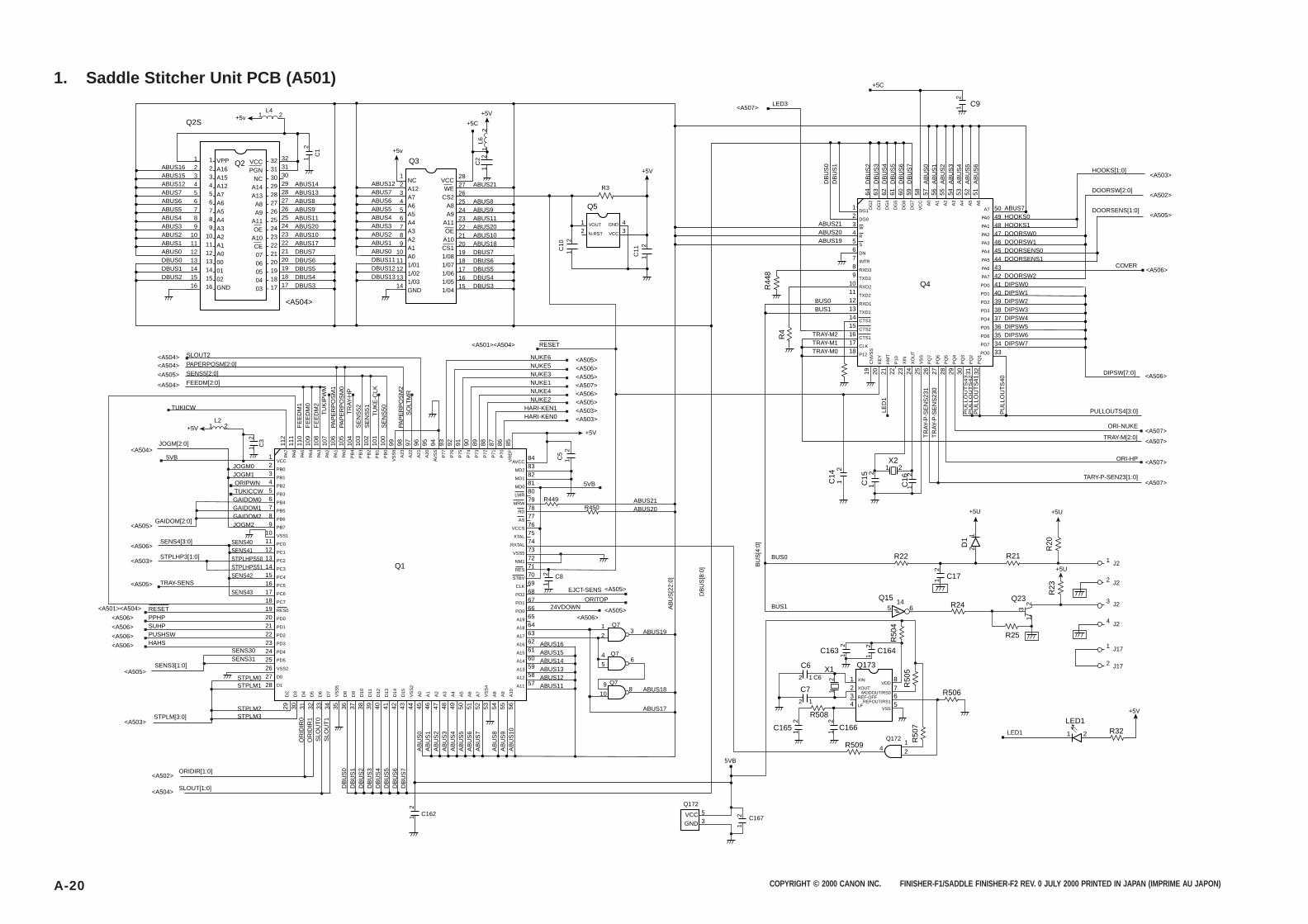
COPYRIGHT © 2000 CANON INC. FINISHER-F1/SADDLE FINISHER-F2 REV. 0 JULY 2000 PRINTED IN JAPAN (IMPRIME AU JAPON)A-20
1. Saddle Stitcher Unit PCB (A501)
+5v
+5v
1 2
1
2
1
21
2
L4
Q2S
Q3Q2ABUS16ABUS15ABUS12ABUS7ABUS6ABUS5ABUS4ABUS3ABUS2ABUS1ABUS0DBUS0DBUS1DBUS2
ABUS14ABUS13ABUS8ABUS9ABUS11ABUS20ABUS10ABUS17DBUS7DBUS6DBUS5DBUS4DBUS3
ABUS21
ABUS8ABUS9ABUS11ABUS20ABUS10ABUS18DBUS7DBUS6DBUS5DBUS4DBUS3
ABUS12ABUS7ABUS6ABUS5ABUS4ABUS3ABUS2ABUS1ABUS0DBUS11DBUS12DBUS13
123456789
10111213141516
123456789
10111213141516
123456789
1011121314
2827262524232221201918171615
VPPA16A15A12A7A6A5A4A3A2A1A0000102GND
NCA12A7A6A5A4A3A2A1A01/011/021/03GND
VCCPGN
NCA14A13
A8A9
A11OE
A10CE0706050403
VCCWE
CS2A8A9
A11OE
A10CS11/081/071/061/051/04
32313029282726252423222120191817
32313029282726252423222120191817
C1
C2
L6
<A504>
<A504><A504>
<A505>
<A504>
<A504>
<A505>
<A506>
<A503>
<A505>
+5C
+5V
R3
Q5
12
43
VOUT
N-RST
GND
VCC
C10
1
2
1
2C
11
+5V
SLOUT2
PAPERPOSM[2:0]
SENS5[2:0]
FEEDM[2:0]
TUKICW
JOGM[2:0]
GAIDOM[2:0]
5VB
+5VL2
1 2
JOGM0JOGM1 ORIPWN TUKICCWGAIDOM0GAIDOM1GAIDOM2JOGM2
123456789
10111213141516171819202122232425262728
84838281807978777675747372717069686766656463626160595857
Q1
ABUS16ABUS15ABUS14ABUS13ABUS12ABUS11
VCCGND
<A501><A504> RESET
NUKE6NUKE5NUKE3NUKE1NUKE4NUKE2
HARI-KEN1HARI-KEN0
<A505><A506><A505><A507><A506><A505><A503><A503>
+5V
5VB
R449R450
ABUS21ABUS20
C8
2 1
2 1
C6
1
2
1
2
1
2
<A505>
<A505><A506>
EJCT-SENS
ORITOP24VDOWN
ABUS19
ABUS18
ABUS17
5VB
LED1
4 65
1 32
9 810
SENS4[3:0]
STPLHP3[1:0]
TRAY-SENS
SENS40SENS41STPLHPS50STPLHPS51SENS42
SENS43
<A501><A504>
<A506>
<A506>
<A506>
<A506>
RESETPPHPSUHPPUSHSWHAHS
<A505>
<A503>
<A502>
<A504>
SENS3[1:0]
SENS30SENS31
STPLM0STPLM1
STPLM2STPLM3STPLM[3:0]
ORIDIR[1:0]
SLOUT[1:0]
C162
C5
1
2
1
2
C167
1
2
C3
1
2
1
2
VCC
PB0
PB1
PB2
PB3
PB4
PB5
PB6
PB7
VSS1
PC0
PC1
PC2
PC3
PC4
PC5
PC6
PC7
RES0
PD0
PD1
PD2
PD3
PD4
PD5
VSS2
D0
D1
AVCC
MD2
MD1
MD0
LWR
MRW
RD
AS
VCCS
XTAL
RXTAL
VSS5
NM1
RES
STBV
CLK
PO2
PO1
PO0
A19
A18
A17
A16
A15
A14
A13
A12
A11
<A507>LED3
+5C
C9
123456789
101112131415161718
504948474645444342414039383736353433
Q4
ABUS21ABUS20ABUS19
BUS0BUS1
TRAY-M2TRAY-M1TRAY-M0
ABUS7HOOKS0HOOKS1DOORSW0DOORSW1DOORSENS0DOORSENS1
DOORSW2DIPSW0DIPSW1DIPSW2DIPSW3DIPSW4DIPSW5DIPSW6DIPSW7
HOOKS[1:0]
DOORSW[2:0]
DOORSENS[1:0]
COVER
DIPSW[7:0]
<A503>
<A502>
<A505>
<A506>
<A506>
<A507>
<A507>
<A507>
<A507>
X21 2
1
2
1
2
1
2
1 3 2
2
1
1
2C
14
C15
C16
1
2
R22
R509
R506
R508
R21
D1
R20
R23
R24
Q173
C17
X1
C163
C6
C7
C164
C165 1
2
C166
R25
Q23
R32LED1
+5U +5U
+5U
+5V
Q155
14 6
1 2
R44
8
R4
R50
4
R50
5R
507
A7
PA0
PA1
PA2
PA3
PA4
PA5
PA6
PA7
PD0
PD1
PD2
PD3
PD4
PD5
PD6
PD7
PO0
DG1
DG0
W
R
S
DN
INTR
RXD3
TXD3
RXD2
TXD2
RXD1
TXD1
CTS3
CTS2
CTS1
CLK
P12
29 30 31 32 33 34 35 36 37 38 39 40 41 42 43 44 45 46 47 48 49 50 51 52 53 54 55 56
OR
IDIR
0O
RID
IR1
SLO
UT
0S
LOU
T1
DB
US
0D
BU
S1
DB
US
2D
BU
S3
DB
US
4D
BU
S5
DB
US
6D
BU
S7
AB
US
0A
BU
S1
AB
US
2A
BU
S3
AB
US
4A
BU
S5
AB
US
6A
BU
S7
AB
US
8A
BU
S9
AB
US
10
D2
D3
D4
D5
D6
D7
VS
S5
D8
D9
D10
D11
D12
D13
D14
D15
VS
S2
A0
A1
A2
A3
A4
A5
A6
A7
VS
S4
A8
A9
A10
PA7
PA6
PA5
PA4
PA3
PA2
PA1
PA0
PB
4
PB
3
PB
2
PB
1
PB
0
VS
S6
A23
A22
A21
A20
AV
SS
P77
P76
P75
P74
P73
P72
P71
P70
VR
EF
112
111
110
109
108
107
106
105
104
103
102
101
100
99 98 97 96 95 94 93 92 91 90 89 88 87 86 85
FE
ED
M1
FE
ED
M0
FE
ED
M2
PAP
ER
PO
SM
1PA
PE
RP
OS
M0
SE
NS
52S
EN
S51
SE
NS
50
PAP
ER
PO
SM
2
TU
KIP
WM
TR
AY-H
P
TU
KE
-CLK
SO
LTM
R
LED
1
19 20 21 22 23 24 25 26 27 28 29 30 31 32
TR
AY-P
-SE
NS
231
TR
AY-P
-SE
NS
230
PU
LL
OU
TS
43
PU
LL
OU
TS
42
PU
LLO
UT
S41
PU
LLO
UT
S40
CN
VS
S
KE
Y
HM
T
P10
XIN
XO
UT
VS
S
PQ
7
PQ
6
PQ
5
PQ
4
PQ
3
PQ
2
PQ
1
DG
2
DG
3
DG
4
DG
5
DG
6
DG
7
VC
C A0
A1
A2
A3
A4
A5
A6
64 63 62 61 60 59 58 57 56 55 54 53 52 51
1
2
DB
US
0D
BU
S1
DB
US
2D
BU
S3
DB
US
4D
BU
S5
DB
US
6D
BU
S7
AB
US
0A
BU
S1
AB
US
2A
BU
S3
AB
US
4A
BU
S5
AB
US
6
AB
US
[22:
0]
DB
US
[8:0
] BU
S[4
:0]
PULLOUTS4[3:0]
ORI-NUKE
TRAY-M[2:0]
ORI-HP
TARY-P-SEN23[1:0]
1 J2
2 J2
3 J2
4 J2
1 J17
2 J17
BUS0
BUS1
Q7
1
24
Q172
Q7
Q7
Q17253
81234
XIN
XOUT
LF
765
REF-OFF
VDD
MODOUT/RS0
REFOUT/RS1
VSS

COPYRIGHT © 2000 CANON INC. FINISHER-F1/SADDLE FINISHER-F2 REV. 0 JULY 2000 PRINTED IN JAPAN (IMPRIME AU JAPON) A-21
1. Saddle Stitcher Unit PCB (A502)
J2
J2
5
6
R33
R40
L8
Q7 Q8Q1102
Q1274
Q1308
Q12
D3
D4
C65
R44
R42
R35
R37
R36
R34
R39
C22
1
2
C19
R38
R41
R43
ICP5
R52
C157
Q28 Q29
Q31Q8
Q168
Q117
Q32
Q30
R51
R50 C158
C27R56
R57
R53
R58
R55
C29
Q9
C20
R207
+24R
+24V
+5V
+5V
+5V
+5V+5U
+5U +5U+5V +5V +5V
Q6
SOLPWM<A504>
1
2
3
4
5
6
7
8
16
15
14
13
12
11
10
9
N.ININ.
ININ1
FB
TCON
CT
RT
GND
C1
IN2
ININ2
ROUT
OCON
VCC
C2
E2
E1
Q25
CP1CP2
L1
2 1
2
1
1
2
1
+2
1
2
1
+2
1
1
1 21
3
2
JNT1
ETH2
J1
J1
J4
J4
J4
J4
1
2
1
2
3
4
J4 5
J4 6
1 2
FRONT DOOR
DELIVERY COVER
INLET DOOR
J
E
1
2
1
2
3
14
7 C66
1
214
7 C67
1
214
7 C69
1
214
7 C70
1
214
7
VCC
GND
VCC
GND
VCC
GND
VCC
GND
VCC
GND
Q16 Q117 Q15 Q17 Q168
C71
1
214
7
12 1113
12 1113
C12
01
214
7 C72
1
214
7 C74
1
214
7 C14
8
2
1
2
1
14
7
2
35
6VCC
GND
VCC
GND
VCC
GND
VCC
GND
VCC
GND
Q13 Q7
4
PRD
KQ
Q
CLR
1 2
1 2 1 2
FOLDING MTRJ4J4
7
8
31
23
1
2
3
3
4
8
4
8
3
1
2
1
2
1
2
1
2
3
3
2
+
-+
-
5
6
1
2
+24R
+5V
7
ETH3
E
23 1
1112 13
11
10
13 12
Q11710 11
13 12
R61
R63
R62
ORIDIROP44<CW>
D52 1
ORIPWM
PB2
PA3
PA2
Q9D6D7
2 11 2
Q8
ORIDIRI
1
2
R60
C28
R64
Q168 Q33
1
23
Q27
1
23
Q26
1
23
Q118
24S<503>
ZD2
ZD3
1 2
1 2
ZD4
1 2
1
2
CB1
C211
+2
R35
9R
46R
48
C12
21
2C
231
2
1
+ 2
C25
+5V
R45
DOORSW1
R358
DOORSW0
DOORSW2
DOORSW[2:0]
+24U
+5V
R47
PA7
P45<CCW>
ORIDIR[1:0]
C26
1
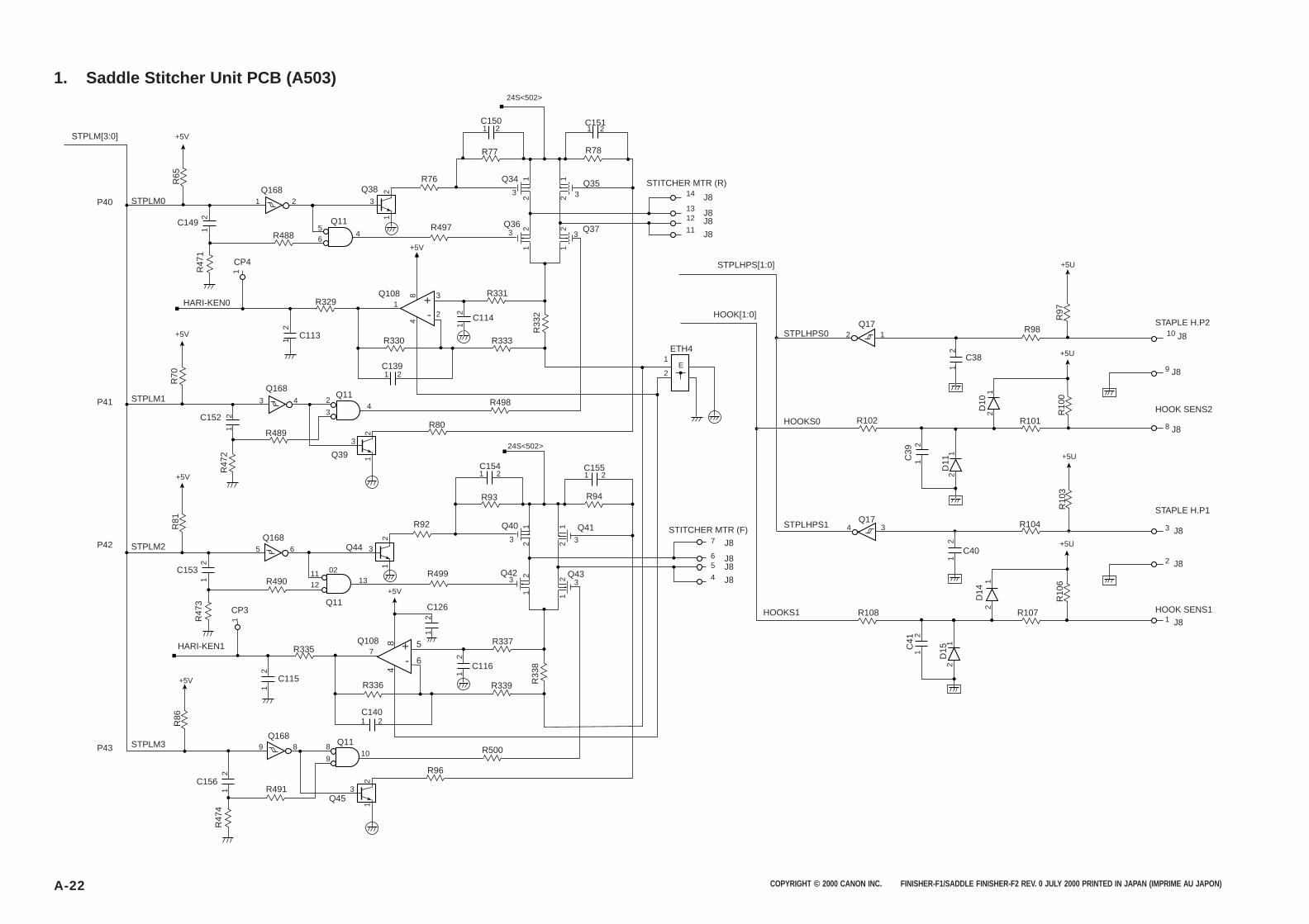
COPYRIGHT © 2000 CANON INC. FINISHER-F1/SADDLE FINISHER-F2 REV. 0 JULY 2000 PRINTED IN JAPAN (IMPRIME AU JAPON)A-22
1. Saddle Stitcher Unit PCB (A503)
STPLM[3:0]
STPLM0
STPLM1
STPLM2
STPLM3
+5V
+5V
+5V
+5V
+5V
R65
R70
R81
R86
R329
R102
R108
R98
R101
R104
R107
R489
R498
R80
R500
R96
R490
R335
R491
R488
R331
R333R330
R76
R497C149
C152
C150
R77 R78
C113
C114
C139
1
2
11
2
1 2
1 2
R336
C1401 2
C1511 2
1
2
2
1
2
1
4
8
1
2
1
2
1
2
C38
1
2
C40
1
2
1
2
1
2
Q168Q34 Q35
Q37Q36Q11
Q11
Q383
1
2
Q39
Q44
3
1
2
Q453
1
2
1
2
3
56
4
2
34
Q11
1112
0213
Q118
910
CP4
CP3
1
2
Q172
1
Q174
3
Q1683
4
Q1685
6
Q1689
8
+ -
P40
P41
P42
P43
R47
1
R47
2
1
2
1
2
1 R47
3
1
2R
474
24S<502>
24S<502>
3
3 3
3
Q108
R33
2 R97
R10
0R
103
R10
6
C39
1
2C
41
2
1
2
1
D10
2
1D
14
D11
2
1
D15
R337
R339
C116
1
2
R33
8
3
21
1
2
4
8 +
-
Q108 5
6
HARI-KEN0
HARI-KEN1
J8
J8J8
J8
14
1312
11
10 J8
9 J8
8 J8
3 J8
2 J8
1 J8
J8
J8J8
J8
7
65
4
1 2C154
R93
1 2C155
R94
Q40 Q41
Q42 Q43
R92
R499
C126
2
1
2
1
3 3
3
1
2
1
23C153
C115
C156
7
+5V
E
STPLHPS[1:0]
STITCHER MTR (R)
STITCHER MTR (F)
HOOK[1:0]
ETH4
STPLHPS0
HOOKS0
HOOKS1
+5U
+5U
+5U
+5U
HOOK SENS1
HOOK SENS2
STAPLE H.P1
STAPLE H.P2
STPLHPS1
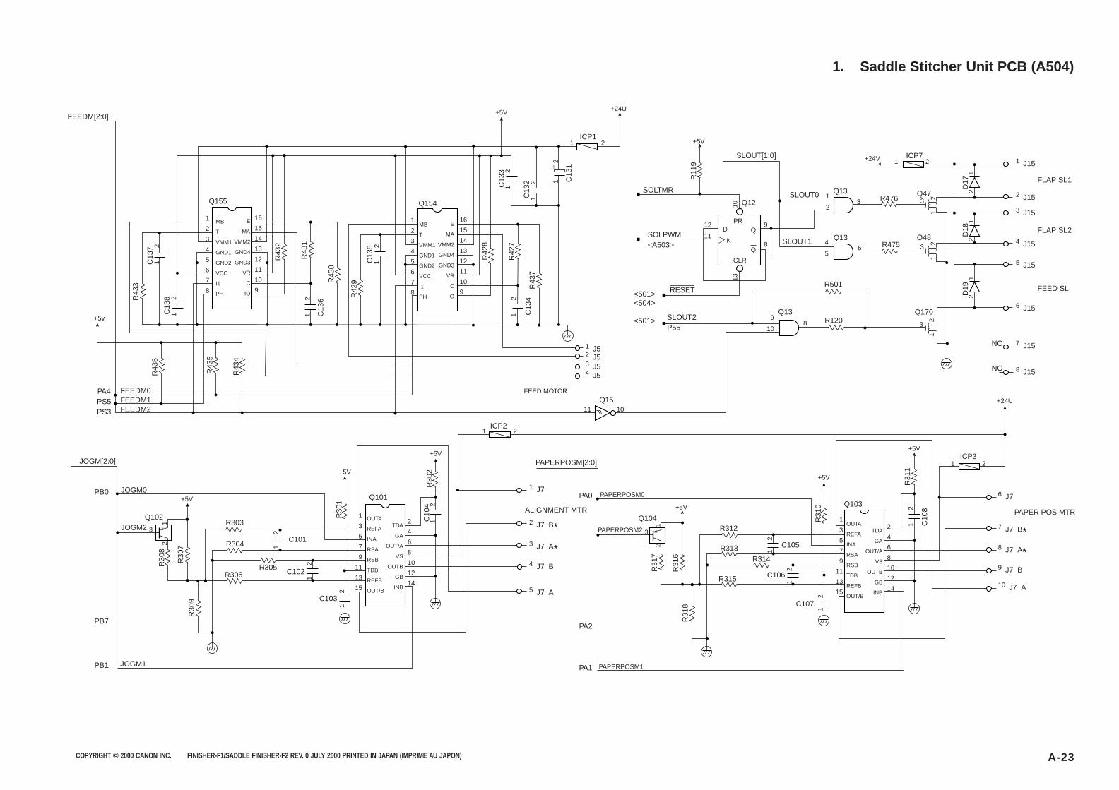
COPYRIGHT © 2000 CANON INC. FINISHER-F1/SADDLE FINISHER-F2 REV. 0 JULY 2000 PRINTED IN JAPAN (IMPRIME AU JAPON) A-23
1. Saddle Stitcher Unit PCB (A504)
C13
7
C13
6
C13
5
C13
4
C13
3
C13
2 C13
1
1
2
C13
81
2
1
2
1
2
1
2
1
2
1
2 1
+
2
C10
41
21 2
1 2
ICP1
ICP2
1 2
ICP71 2
R475
R476
R501
R120
R303R312
R313
R314
R315
R304
R305R306
D17
2
13
Q101
1
2
3
4
5
6
7
8
16
15
14
13
12
11
10
9
E
MA
VMM2
GND4
GND3
VR
C
IO
E
MA
VMM2
GND4
GND3
VR
C
IO
1
2
3
4
5
6
7
8
16
15
14
13
12
11
10
9
MB
T
VMM1
GND1
GND2
VCC
I1
PH
MB
T
VMM1
GND1
GND2
VCC
I1
PH
1
3
5
7
9
11
13
15
2
4
6
8
10
12
14
OUTA
REFA
INA
RSA
RSB
TDB
REFB
OUT/B
TDA
GA
OUT/A
VS
OUTB
GB
INB
1 32
Q13 Q47
Q48
Q170
4 65
Q13
9 810
Q13
Q12
12
11
9
8
13
10
PRD
K
Q
Q
CLR
R42
9
R30
8
R30
7
R30
9
R30
2
R31
7
R31
6R
318
R30
1
R43
6
R43
5
R43
4
R43
3
R43
2
R43
1
R42
8
R42
7
R11
9
R43
0
R43
7
1
2
2
1
D18
2
1
D19
2
1
3
1
23
1
23
1
2
C102
C103
C101
1
2
1
2
1
2
1 J15
2 J15
3 J15
4 J15
5 J15
6 J15
7 J15
8 J15
1 J52 J5
1 J7
2 J7 B*3 J7 A*4 J7 B
5 J7 A
3 J54 J5
+5v
Q155 Q154
+5V
+5V
+24U
SOLTMR
SOLPWM<A503>
SLOUT[1:0]
RESET
SLOUT1
SLOUT2P55
<501><504>
<501>
SLOUT0
+24V
FLAP SL1
FLAP SL2
FEED SL
NC
NC
FEED MOTOR
FEEDM[2:0]
JOGM[2:0]
JOGM0
JOGM2
JOGM1
PA4PS5PS3
FEEDM0FEEDM1FEEDM2
Q102
2
13
Q104
PB7
PB0
PB1
+5V+5V
+5V
+5V
ALIGNMENT MTR
C10
8
1
2
ICP3
Q103
1
3
5
7
9
11
13
15
2
4
6
8
10
12
14
OUTA
REFA
INA
RSA
RSB
TDB
REFB
OUT/B
TDA
GA
OUT/A
VS
OUTB
GB
INB
R31
1
R31
0
C106
C107
C105
1
2
1
2
6 J7
7 J7 B*8 J7 A*9 J7 B
10 J7 A
+5V
+24U
+5V
PAPER POS MTR
PA0
PA2
PA1
PAPERPOSM[2:0]
PAPERPOSM0
PAPERPOSM2
PAPERPOSM1
Q1511
10
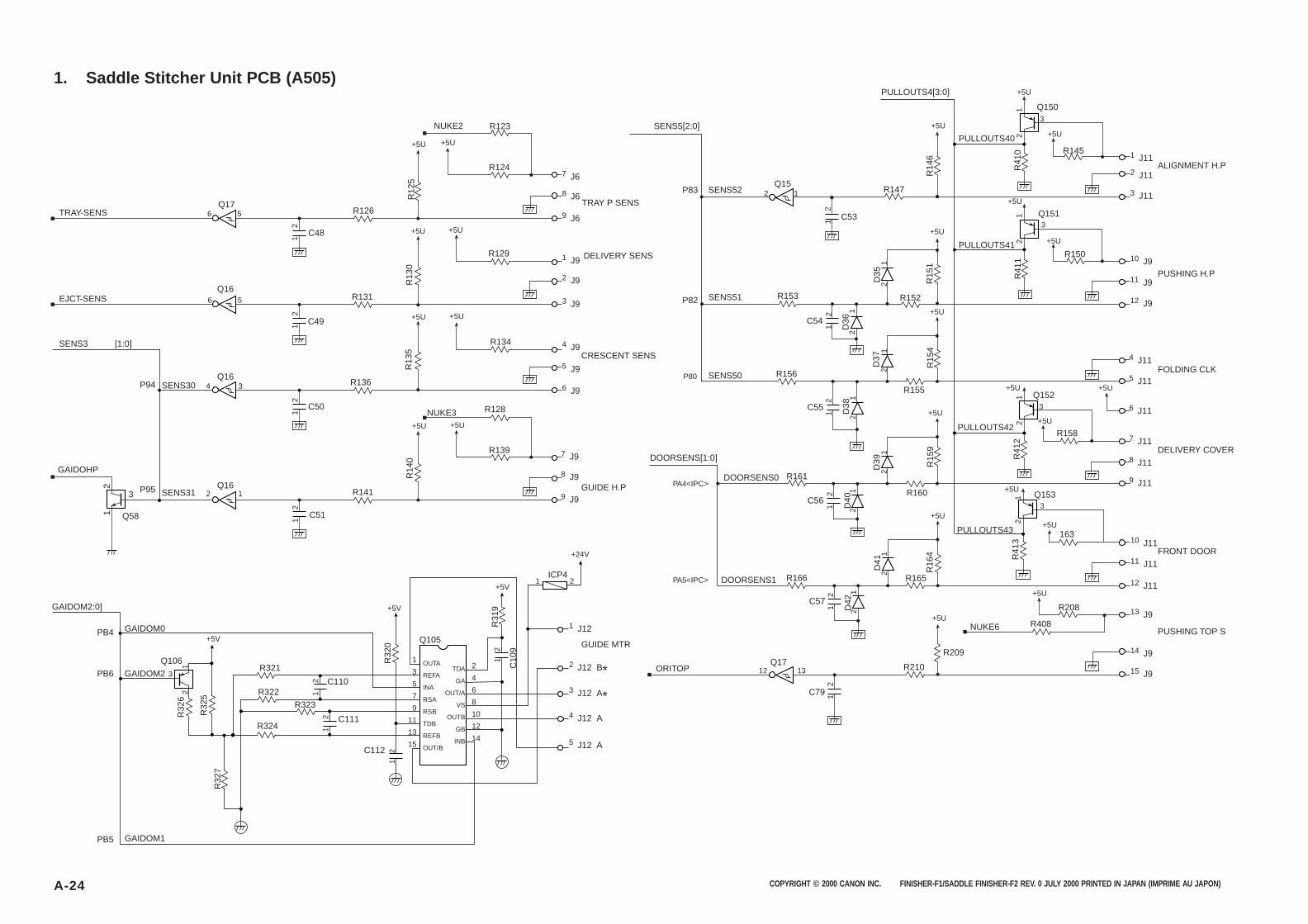
COPYRIGHT © 2000 CANON INC. FINISHER-F1/SADDLE FINISHER-F2 REV. 0 JULY 2000 PRINTED IN JAPAN (IMPRIME AU JAPON)A-24
1. Saddle Stitcher Unit PCB (A505)
R12
5
R126
R124
R129
R123
C48
R13
0
R131
C49
R13
5
R136
R134
C50R
140
R141
R139
R128
C511
2
1
21
2
1
21
2
Q17
Q58
3
Q150
Q151
3
3
2
12
1
2
12
1
Q1523
Q1533
6 5
6 5
R14
6R
151
R15
4R
159
R209
R16
4 R41
3R
412
R41
1R
410
R147
R152
R155
R160
R165
R408
R208
163
R158
R150
R145
R210
R161
R166
R156
R153
C531
2
C54
1
2
C79 1
2
Q15
Q16
4 3
2
1
12
13
Q16
2 1
Q16
Q17
2
1
D41
2
1
D35
2
1
D37
2
1
D39
2
1
D36
C55
1
2
2
1
D38
1
2
2
1
D40
C57
C56
1
2
2
1
D42
C10
9
1 2
1 2ICP4
R321
R322
R323
R324
2
1
3
Q105
1
3
5
7
9
11
13
15
2
4
6
8
10
12
14
OUTA
REFA
INA
RSA
RSB
TDB
REFB
OUT/B
TDA
GA
OUT/A
VS
OUTB
GB
INB
R32
6
R32
5
R32
7
R31
9
R32
0
1
2
C112
C110
C111
1
2
1 2
1 J12
7 J6
1 J11
2 J11
3 J11
10 J9
11 J9
12 J9
4 J11
5 J11
6 J11
7 J11
8 J11
9 J11
10 J11
11 J11
12 J11
13 J9
14 J9
15 J9
8 J6
9 J6
1 J9
2 J9
3 J9
4 J9
5 J9
6 J9
2 J12 B*3 J12 A*4 J12 A
5 J12 A
GAIDOM2:0]
GAIDOM0
GAIDOM2
GAIDOM1
Q106
PB4
PB5
PB6
+5V
+5V
+24V
+5V
SENS5[2:0]
DOORSENS[1:0]
PULLOUTS4[3:0]
PULLOUTS40
PULLOUTS41
PULLOUTS42
PULLOUTS43
DOORSENS0
DOORSENS1
TRAY-SENS
EJCT-SENS
SENS3 [1:0]
P94
P95
SENS30
SENS31
GAIDOHP
+5U
+5U
+5U
+5U
+5U
+5U
+5U
+5U
+5U
+5U
+5U
+5U
+5U
+5U
+5U
+5U
+5U
+5U+5U
+5U +5U
+5U
+5U
+5U
NUKE3
TRAY P SENS
DELIVERY SENS
CRESCENT SENS
7 J9
8 J9
9 J9GUIDE H.P
GUIDE MTR
P80
P83
P82
SENS52
SENS51
SENS50
ALIGNMENT H.P
PUSHING H.P
FOLDING CLK
DELIVERY COVER
PA4<IPC>
PA5<IPC>
ORITOP
NUKE6
NUKE2
PUSHING TOP S
FRONT DOOR
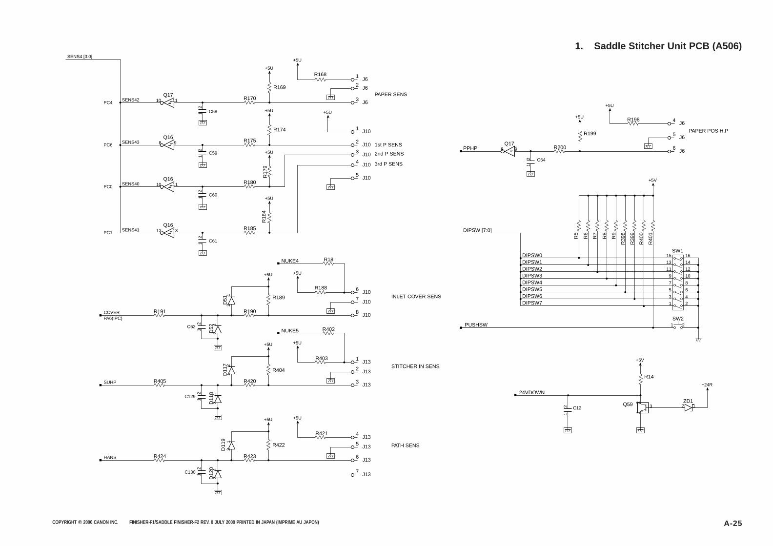
COPYRIGHT © 2000 CANON INC. FINISHER-F1/SADDLE FINISHER-F2 REV. 0 JULY 2000 PRINTED IN JAPAN (IMPRIME AU JAPON) A-25
1. Saddle Stitcher Unit PCB (A506)
J63
J61
J6PAPER SENS
INLET COVER SENS
STITCHER IN SENS
PATH SENS
1st P SENS
2nd P SENS
3rd P SENS
2
J105
J135
R170
R169
+5U
R422
+5U
+5U
Q1710
11
1
2 3Q59
D11
92
1
D12
02
1
R168
J134
+5U
R421
J101
+5U1 2 C58
SENS42
SENS4 [3:0]
PC4
J102R175
J136
J137
R423R424
R174
+5U
Q16
J66
J6PAPER POS H.P
5
J64
R200
R198
R199
+5U
R14
+5V
+24R
R5
R6
R7
R8
R9
R39
8
R39
9
R40
0
R40
1
+5V
+5U
Q178
9
1 2 C64
1
2 C12
PPHP8
9
1 2 C59
SENS43PC6
J103
R180
R17
9
+5U
Q1610
11
1 2 C60
SENS40PC0
J104
R185
R18
4
+5U
Q1612
13
1 2 C61
SENS41
COVERPA6(IPC)
SUHP
HANS
PC1
1 2C130
J132R404
+5U
D11
71
2
D11
82
1
J131
NUKE5
+5U
R403
J133R420R405
R402
1 2C129
J107R189
+5U
D51
2
1
D52
2
1
J106
NUKE4
+5U
R188
J108R190R191
R18
1 2C62
DIPSW0
DIPSW [7:0]
DIPSW1DIPSW2DIPSW3DIPSW4DIPSW5DIPSW6DIPSW7
SW21 2
SW1
PUSHSW
24VDOWN
ZD12 1
1
3
5
7
9
11
13
15
2
4
6
8
10
12
14
16
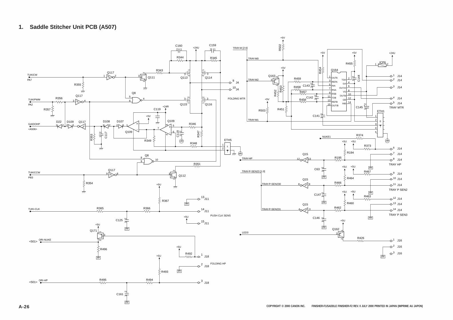
COPYRIGHT © 2000 CANON INC. FINISHER-F1/SADDLE FINISHER-F2 REV. 0 JULY 2000 PRINTED IN JAPAN (IMPRIME AU JAPON)A-26
1. Saddle Stitcher Unit PCB (A507)
912
3
Q8
Q8
Q117
R355
TUKICW
PA7
TRAY-HP
TRAY-P-SEN23 [1:0]
TRAY-P-SEN230
TRAY-M1
TRAY-M2
TRAY-M0
TRAY-M [2:0]
FOLDING MTR
TRAY-P-SEN231
LED3
NUKE1
R343
Q113 Q114
Q116Q115
R344
C160
2
1
2
1
2 1
R345
C1592 1
3 3
+24U
J4
J4
13J11
3J18
1J18
2J18
14J11
15J11
Q117
C119
R346
R349
R367
Q112C
118
Q109
Q111
1
23
+
-+
-
+24R
+5U
R493
+5U
+5U
+5U
+5U
+5V
ETH5
3 4
1 2
Q117
4
8
1
2
9 8
R357
D1092 1
D221 2
Q109
D108 D1072 1 1
4
7
3 3
E
10
10
6
5
1 2
1
2
1
2
1
2
R35
3
C11
7
1 2C125
1
2
R354
Q117
R351
R34
7
R348
GAIDOHP
<A506>
TUKICCW
PB3
TUKI-CLK
PUSH CLK SENS
FOLDING HP
ORI-NUKE
TUKIPWM
PA2
R356
Q171
2
1
3
R365 R366
<501>
ORI-HP<501>
R496
R494R495
R492
R374
R194
1 2
C63
1 2
C14
4
1 2
C142
C141
1 2
C143 1 2
R455 ICP6
C145
+5U
R503
+5V
+5V
+5V
+5V +5V +24U
+5U
Q164
1 +
2
ETH1
E
1
2
3
4
5
OUTA
REFA
INA
RSA
RSB
TDB
REFB
OUT/B
TDA
GA
OUT/A
VS
OUTB
GB
INB
1
3
5
7
9
11
15
13
2
4
6
8
10
14
12
R451
R45
2
R50
2R
453
TRAY HP
J147
J1410
J162
J141
J142
J143
J144
J14
TRAY MTR
5
J148
J146R373
+5U
J149
R456
R457
R458
R459
R45
4
1
2
3
Q163
Q15
12 13 R195
J161
J163
R426
R464
C147
1 2
+5U
TRAY P SEN2
J1411
Q15
8 9 R466
J1413
+5U
J1412
R460
C146
1 2
+5U
+5U
TRAY P SEN3
J1414
Q15
4 3 R462
R463
R467
Q162
2
1
3
1 2
C161
5
6
12
89
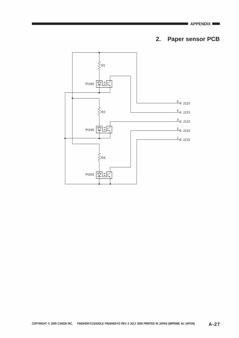
COPYRIGHT © 2000 CANON INC. FINISHER-F1/SADDLE FINISHER-F2 REV. 0 JULY 2000 PRINTED IN JAPAN (IMPRIME AU JAPON) A-27
APPENDIX
2. Paper sensor PCB
5 J123
PI18S
PI19S
R1
R2
PI20S
R3
4 J123
3 J123
2 J123
1 J123

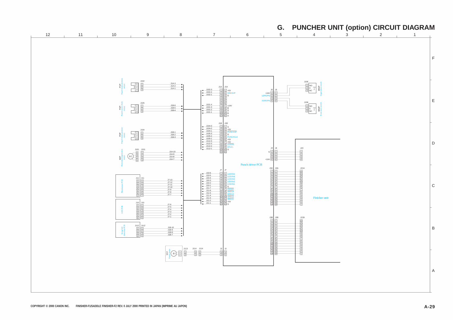
COPYRIGHT © 2000 CANON INC. FINISHER-F1/SADDLE FINISHER-F2 REV. 0 JULY 2000 PRINTED IN JAPAN (IMPRIME AU JAPON) A-29
G. PUNCHER UNIT (option) CIRCUIT DIAGRAM
123
NOCNC
123456789
1011121314
123456789
1011121314
J106
123
NOCNC
J106
J2
12
12
J114J114
12
12
123456789
1011
J1A
123456789
1011
J102-3J102-2J102-1
J101-4J101-3J101-2J101-1
123456789
1011
J1B
123456789
1011
J104-3J104-2J104-1J105-3J105-2J105-1J112-4J112-3J112-2J112-1
123456789
10111213
J7
123456789
10111213
J10-6J10-5J10-4J10-3J10-2J10-1J11-7J11-6J11-5J11-4J11-3J11-2J11-1
12
12
123
123
1234
4321
J1A-3J1A-2J1A-1
J113
J102
J101J101J1A-10J1A-9J1A-8J1A-7
1234567
1234567
J11J11J7-13J7-12J7-11J7-10J7-9J7-8J7-7
123456
123456
J10J10J7-6J7-5J7-4J7-3J7-2J7-1
1234
1234
J112J112J1B-10J1B-9J1B-8J1B-7
M2P
PI1
P
123
123
J1B-6J1B-5J1B-4
J105
PI2
P
123
123
J1B-1J1B-2J1B-3
J104
PI3
P
M
J3B
1413121110987654321
J21B
123456789
1011121314
123456789
1011121314
J3A
1413121110987654321
J21A
1234
1234
J4
1234
1234
J5
1234
J23
M
J2
J1A
+5V
G
+24VBABA
J1B
J7
J3B
J3A
J4
J5
G+5V
G
+5V+5V
G
G
+5VG
G
+24V
+24V
M1P
MS
1PM
S2P
LED
PC
BP
hoto
sens
or P
CB
Hor
izon
tal r
egis
trat
ion
mot
orP
unch
mot
or c
lock
se
nsor
Pun
ch h
ome
posi
tion
sens
orP
unch
hom
e po
sitio
n se
nsor
Pun
ch m
otor
Punch driver PCB
Upp
er d
oor
switc
hF
ront
doo
r sw
itch
Finisher unit
Scr
ap fu
ll de
tect
ion
PC
B
LEDON5LEDON4LEDON3LEDON2LEDON1
PAENDSREG4SREG3SREG2SREG1
PUNCHHP
PUNCHCLK
LEDONDFULL
SREGHPUDROPN
FDROPN
A
B
C
D
E
F
123456789101112
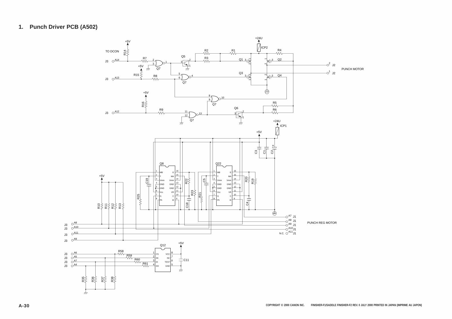
COPYRIGHT © 2000 CANON INC. FINISHER-F1/SADDLE FINISHER-F2 REV. 0 JULY 2000 PRINTED IN JAPAN (IMPRIME AU JAPON)A-30
1. Punch Driver PCB (A502)
R4
J2
+24U
ICP2
R7
R2
R3
R1
Q5Q1 Q2
Q4
J3
TO DCON
PUNCH REG MOTOR
PUNCH MOTOR
A14 2
31 3
2 3 1
+5V
R15 R8Q3
R9
Q7
R6
R5
Q6A12 11
1213 3
2
1
1Q7
8
910
Q7
Q7J3
J3
A13
5
64 3
32
J21
322
1
12
21
+5V
R16
+5V
R14
J3
C11
+5V
R35
R36
R37
R38
A6 R58
J3 A5 R59
J3 A7 R60
J3 A4 R61 4
3
2
1
5
6
7
8
GND
TEST
NC
VCC
DO
DI
SK
CS
Q12
+24U
ICP1
+5V
C3
C1
C2
+
Q8 Q22
R25
R13
R12
R11
R10
R22
R21R
23
C19
C18
C5
R20
R19
C4
MB
T
Vmm
GND
GND
Vcc
I1
Ph
E
MA
Vmm
GND
GND
VR
C
I0
MB
T
Vmm
GND
GND
Vcc
I1
Ph
E
MA
Vmm
GND
GND
VR
C
I0
1
2
3
4
5
6
7
8
16
15
14
13
12
11
10
9
1
2
3
4
5
6
7
8
16
15
14
13
12
11
10
9
+5V
A8
A7
A8
A9
A10
A11
A10
A11
A9
J3J3
J3
J3
J1J1J1J1J1N.C.
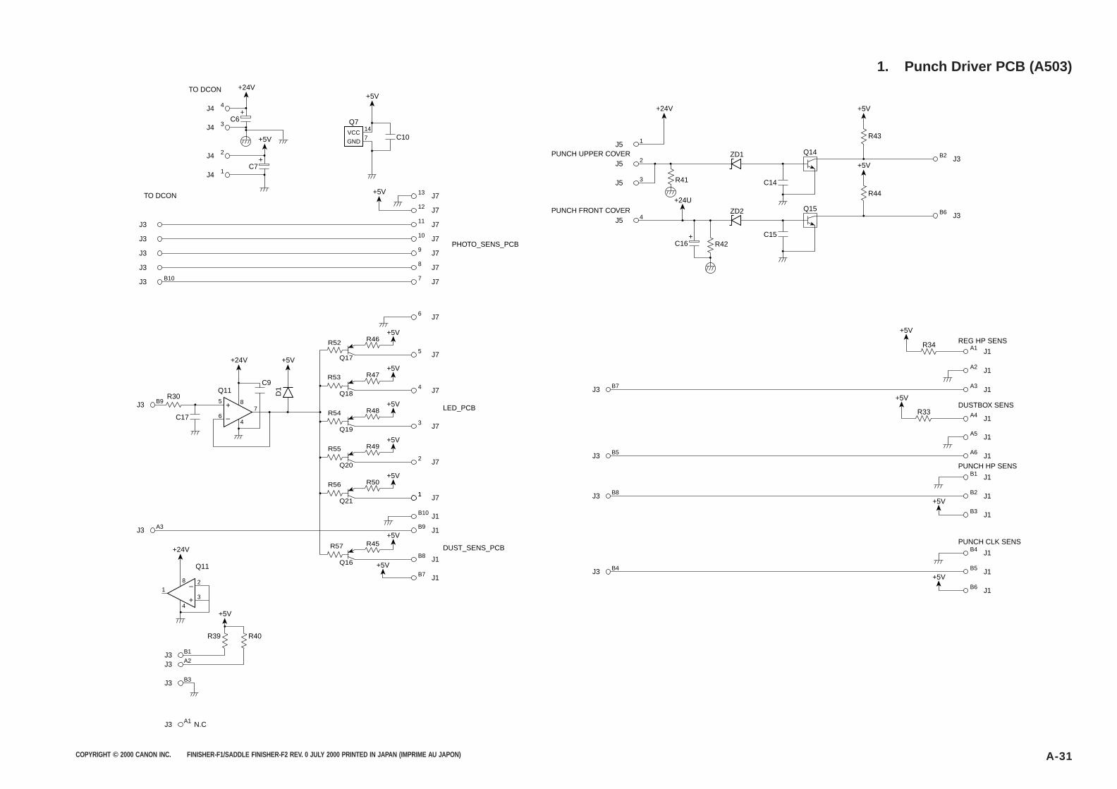
COPYRIGHT © 2000 CANON INC. FINISHER-F1/SADDLE FINISHER-F2 REV. 0 JULY 2000 PRINTED IN JAPAN (IMPRIME AU JAPON) A-31
1. Punch Driver PCB (A503)
4
VCC
GND
Q7
J4
314
7
J4
TO DCON
11J3 J7
B2 J3
10J3 J7
13 J7
6 J7
5 J7
+5V
12 J7
9J3 J78J3 J7
B10 7J3 J7
TO DCON
PHOTO_SENS_PCB
C6+
C10
+5V
+5V
+24V
2J4
1J4
B97
8
4
5
6
J3
A3J3
1J5
2J5PUNCH UPPER COVER
3J5
C7+
+5V
R30
R46
Q17
R52
4 J7
LED_PCB
DUST_SENS_PCB
+5VR47
Q18
R53
3 J7
+5VR48
Q19
R54
2 J7
+5VR49
Q20
R55
11
B10
B9
J7
J1
J1
+5VR50
Q21
R56
B8 J1
B7 J1
+5V
+5V
R45
Q16
R57
B7J3
DUSTBOX SENS
PUNCH HP SENS
REG HP SENS
A2
A3
J1
J1
B5J3 A6 J1
A4 J1
A5 J1
B8J3 B2 J1
B1 J1
A1 J1
+5V
B3 J1
+5V
PUNCH CLK SENS
B4J3 B5 J1
B4 J1
B6 J1
+5V
+5V
R33
R34
D1
C17
C9Q11
+24V
B1J3A2J3
B3J3
A1J3 N.C
R40R39
+5V
R43
+5V+24V
+24U
R41
1
8
4
2
3
Q11
+24V
+5V
ZD1 Q14
C14
B6 J34J5PUNCH FRONT COVER
R44
+5V
R42
ZD2 Q15
C15C16
+

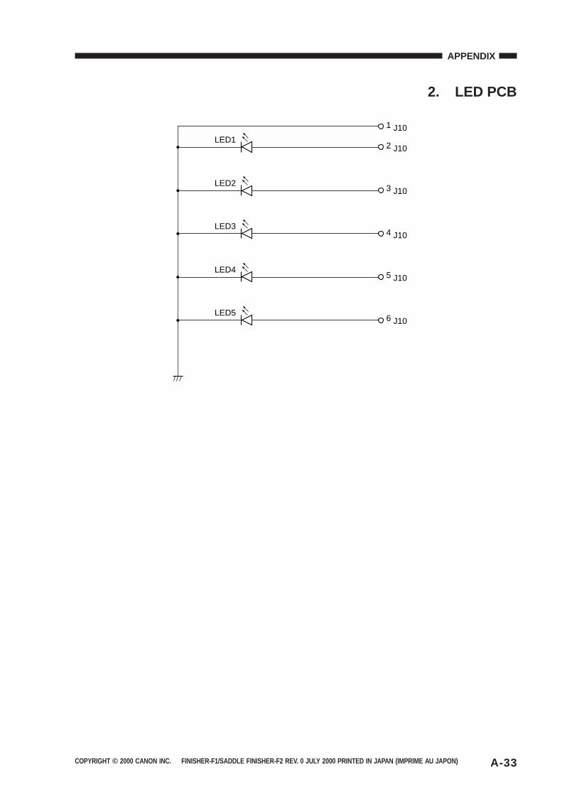
COPYRIGHT © 2000 CANON INC. FINISHER-F1/SADDLE FINISHER-F2 REV. 0 JULY 2000 PRINTED IN JAPAN (IMPRIME AU JAPON) A-33
APPENDIX
2. LED PCB
1 J10
2 J10
3 J10
4 J10
5 J10
6 J10
LED2
LED3
LED4
LED5
LED1

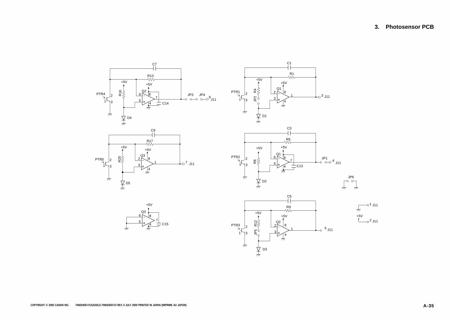
COPYRIGHT © 2000 CANON INC. FINISHER-F1/SADDLE FINISHER-F2 REV. 0 JULY 2000 PRINTED IN JAPAN (IMPRIME AU JAPON) A-35
3. Photosensor PCB
C7
C14
R13
Q2
+5V+5V
PTR4 2
31
2
31
6
5
JP3 JP46-
+
D4R
16
C9
R17
Q3
+5V+5V
PTR5 2
3
8
4
1 J11
J11
7-
+
D5
R20
C1
R1
Q1
+5V+5V
2
32
31
1
J113-
+
D1
R4
JP2
C3
C13
R5
Q1
+5V+5V
PTR2 2
3
6
5
JP1
JP6
1 J11
2 J11
4-
+
D2
R8
C5
R9
Q2
+5V+5V
PTR3 2
31
2
3
8
4
1 5 J11-
+
D3
R12
JP5
C15
Q3
+5V
6
5
8 74
-
+
J11
+5V
87
4
8
4
1
8
4
7
PTR1

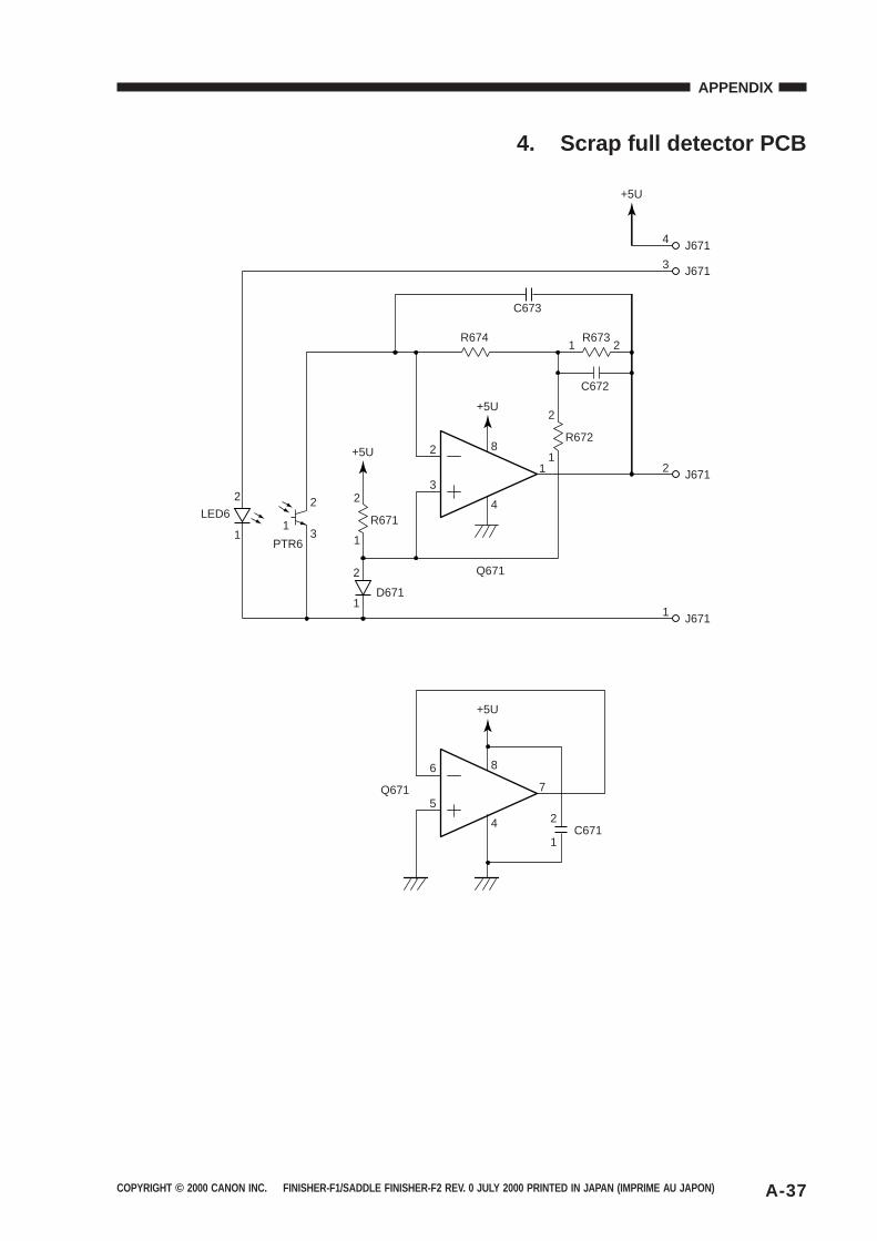
COPYRIGHT © 2000 CANON INC. FINISHER-F1/SADDLE FINISHER-F2 REV. 0 JULY 2000 PRINTED IN JAPAN (IMPRIME AU JAPON) A-37
APPENDIX
4. Scrap full detector PCB
LED6
PTR6
2
2
1
2
1
3
D671
R671
2
1
21
8
4
3
R672
Q671
Q671
R673R674
C672
2 J671
1 J671
3 J671
4 J671
+5U
+5U
+5U
+5U
2
1
2
1
11
2
6
57
8
4C671
C673
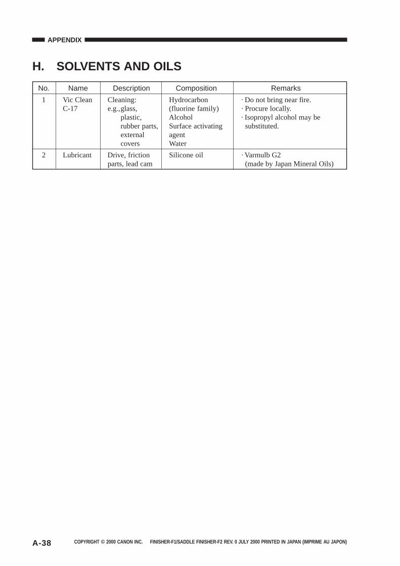
COPYRIGHT © 2000 CANON INC. FINISHER-F1/SADDLE FINISHER-F2 REV. 0 JULY 2000 PRINTED IN JAPAN (IMPRIME AU JAPON)A-38
APPENDIX
H. SOLVENTS AND OILS
No. Name Description Composition Remarks
1 Vic Clean Cleaning: Hydrocarbon · Do not bring near fire.C-17 e.g.,glass, (fluorine family) · Procure locally.
plastic, Alcohol · Isopropyl alcohol may berubber parts, Surface activating substituted.external agentcovers Water
2 Lubricant Drive, friction Silicone oil · Varmulb G2parts, lead cam (made by Japan Mineral Oils)

Prepared byOffice Imaging Products Technical Support Dept. 3Office Imaging Produce Quality Assurance Center.
CANON INCPrinted in Japan
REVISION 0 (JULY 2000)(01073)
5-1, Hakusan 7-chome, Toride-shi Ibaraki, 302-8501 Japan

This publication is printed on 70% reprocessed paper.
PRINTED IN JAPAN (IMPRIME AU JAPON) 0800AB1.05-1