final year building project presentation
DESCRIPTION
Building project presentationTRANSCRIPT

TRIBHUWAN UNIVERSITYKATHMANDU ENGINEERING COLLEGE
KALIMATI, KATHMANDU
PREPARED BY: SUBMITTED TO: DEPARTMENT OF CIVIL
ENGINEERINGKATHMANDU ENGINEERING
COLLEGE
SHREEJAL UPRETY BCE 68102SONIK PRADHAN BCE 68104
SUDEEN SHRESTHA BCE 68106SUJAN BIKRAM SHAHI BCE 68108 UMESH RAI BCE 68119YADAV RANA BCE 68121
SEISMIC RESISTANT DESIGN OF RCC FRAMED COMMERCIAL BUILDING
INTRODUCTION
RCC FRAMED MULTIPURPOSE BUILDING:
Essential due to limitation of availability of land in urbanized areas. Proper earthquake consideration essential in case of Kathmandu valley
(as it falls under zone V most severe one).
OBJECTIVES
•Structural analysis and design of various members using Limit State Method.
•Build structurally seismic safe building.
•Resist all predictable forces throughout its life, so that the building does not
become unserviceable prior to its life.
SCOPE OF THE PROJECT
•Application of course of study in real field basically on structural analysis and design of R.C.C. structures by limit state method of design.
•Application of various tools and software for designing seismic resistant structure.
•Detail design of cost effective and safe structural member such as slab, column, staircase, footing etc.
•Application of course of study in real field basically on structural analysis and design of R.C.C. structures by limit state method of design.
DESCRIPTION OF PROPOSED BUILDING
•Building Type: Multistoried RCC Framed Commercial
Building
•Structure System: RCC framed structure
•Plinth Area: 819.504 sq. m
•No. of Storey: 8
•Method of Analysis: Limit State Method of Design
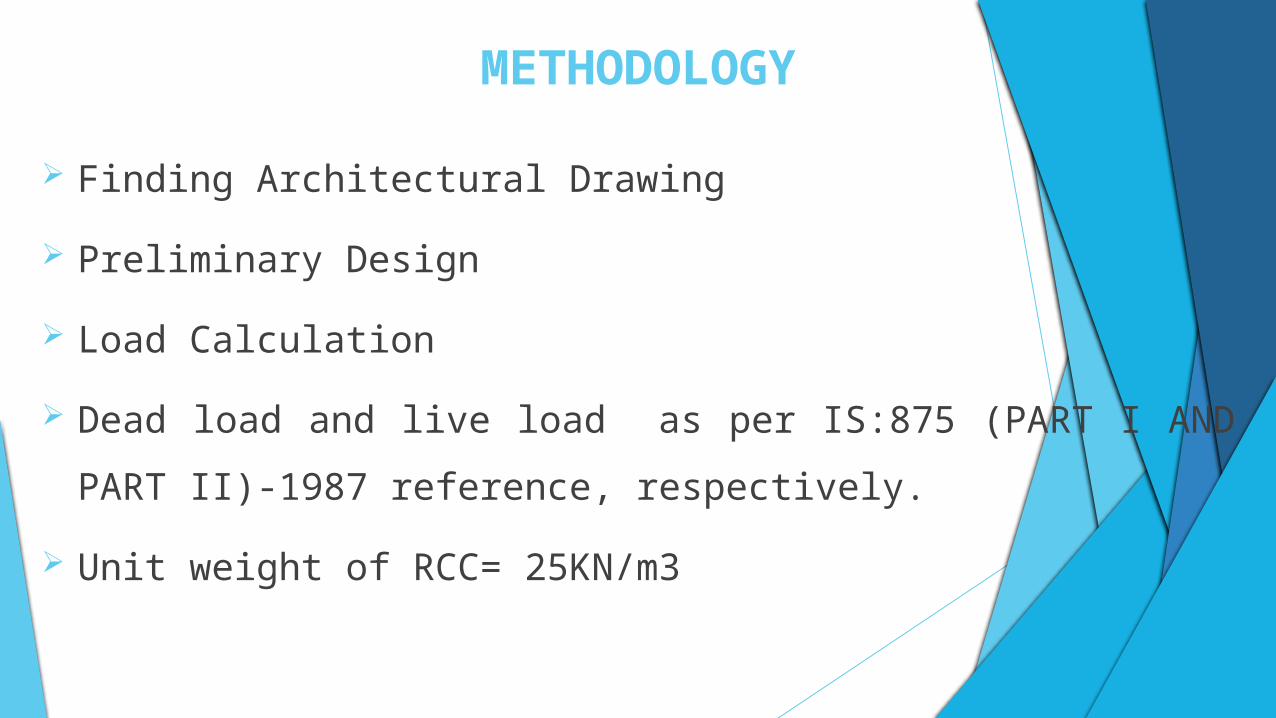
METHODOLOGY
Finding Architectural Drawing
Preliminary Design
Load Calculation
Dead load and live load as per IS:875 (PART I AND PART II)-1987
reference, respectively.
Unit weight of RCC= 25KN/m3
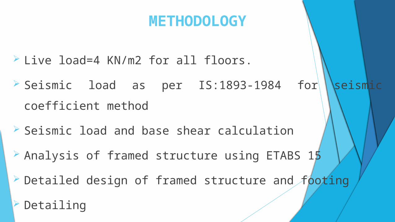
METHODOLOGY
Live load=4 KN/m2 for all floors.
Seismic load as per IS:1893-1984 for seismic coefficient method
Seismic load and base shear calculation
Analysis of framed structure using ETABS 15
Detailed design of framed structure and footing
Detailing
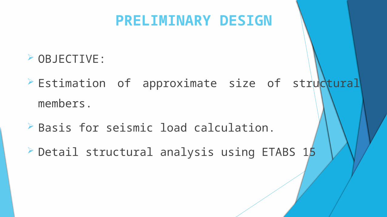
PRELIMINARY DESIGN
OBJECTIVE:
Estimation of approximate size of structural members.
Basis for seismic load calculation.
Detail structural analysis using ETABS 15
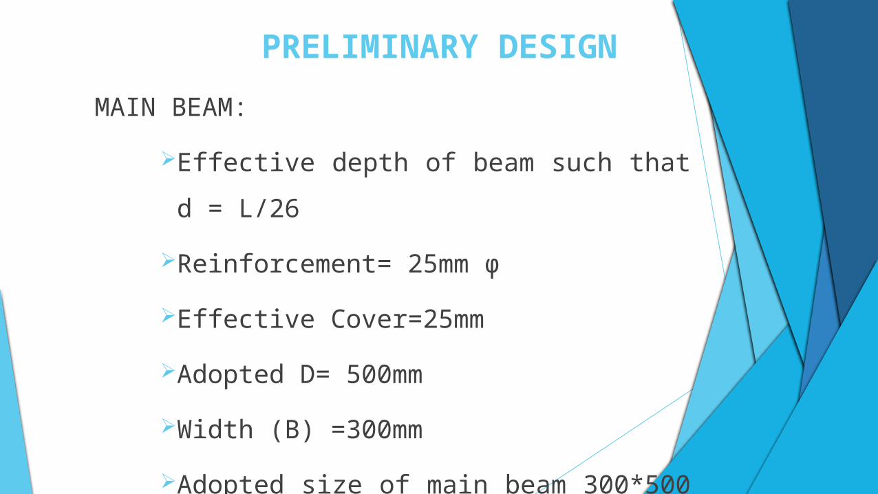
PRELIMINARY DESIGN
MAIN BEAM:
Effective depth of beam such that d = L/26
Reinforcement= 25mm ϕ
Effective Cover=25mm
Adopted D= 500mm
Width (B) =300mm
Adopted size of main beam 300*500 mm.
PRELIMINARY DESIGN
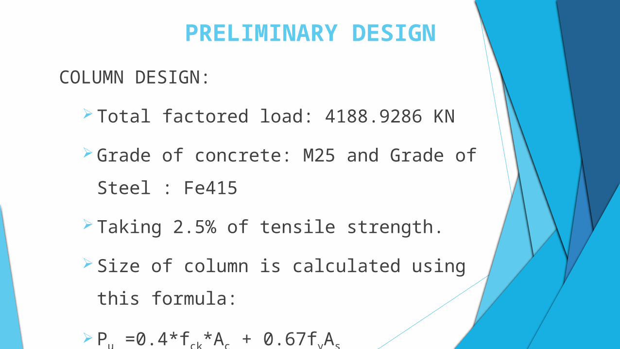
COLUMN DESIGN:
Total factored load: 4188.9286 KN
Grade of concrete: M25 and Grade of Steel : Fe415
Taking 2.5% of tensile strength.
Size of column is calculated using this formula:
Pu =0.4*fck*Ac + 0.67fyAs
Size of column adopted: 600 mm * 600 mm
PRELIMINARY DESIGN
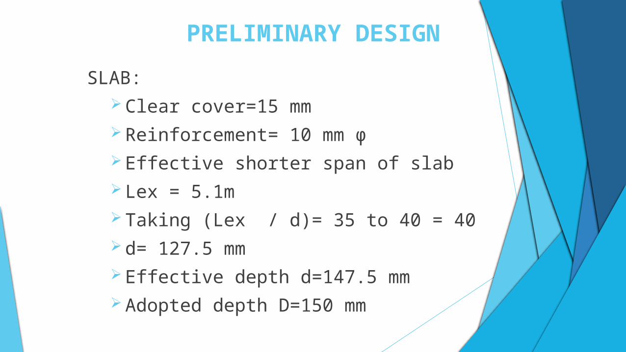
SLAB: Clear cover=15 mm Reinforcement= 10 mm ϕ Effective shorter span of slab Lex = 5.1m Taking (Lex / d)= 35 to 40 = 40 d= 127.5 mm Effective depth d=147.5 mm Adopted depth D=150 mm
SEISMIC LOAD AND BASE SHEAR CALCULATION
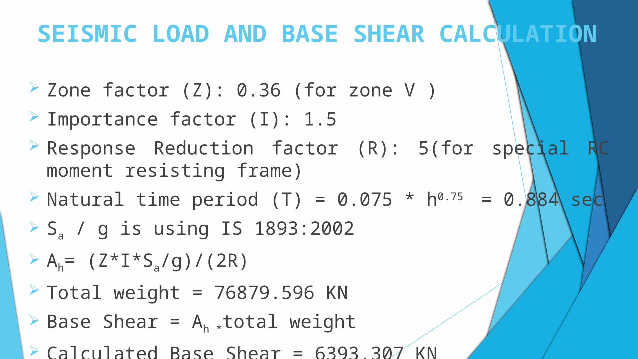
Zone factor (Z): 0.36 (for zone V ) Importance factor (I): 1.5 Response Reduction factor (R): 5(for special RC moment resisting frame) Natural time period (T) = 0.075 * h0.75 = 0.884 sec
Sa / g is using IS 1893:2002
Ah= (Z*I*Sa/g)/(2R)
Total weight = 76879.596 KN
Base Shear = Ah *total weight
Calculated Base Shear = 6393.307 KN
CALCULATION OF SEISMIC LOAD
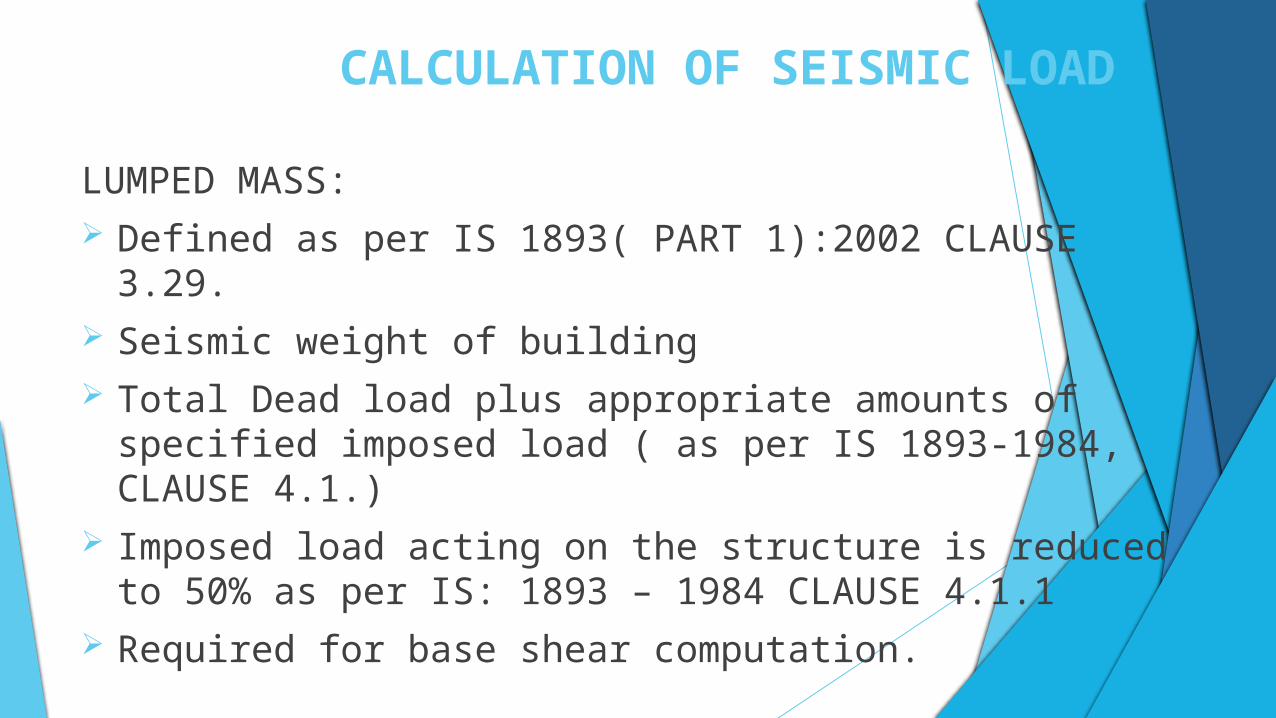
LUMPED MASS: Defined as per IS 1893( PART 1):2002 CLAUSE 3.29. Seismic weight of building Total Dead load plus appropriate amounts of specified imposed load ( as
per IS 1893-1984, CLAUSE 4.1.) Imposed load acting on the structure is reduced to 50% as per IS: 1893 –
1984 CLAUSE 4.1.1 Required for base shear computation.
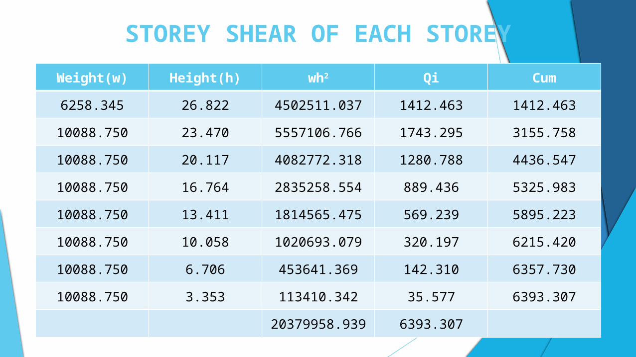
STOREY SHEAR OF EACH STOREY
Weight(w) Height(h) wh2 Qi Cum
6258.345 26.822 4502511.037 1412.463 1412.463
10088.750 23.470 5557106.766 1743.295 3155.758
10088.750 20.117 4082772.318 1280.788 4436.547
10088.750 16.764 2835258.554 889.436 5325.983
10088.750 13.411 1814565.475 569.239 5895.223
10088.750 10.058 1020693.079 320.197 6215.420
10088.750 6.706 453641.369 142.310 6357.730
10088.750 3.353 113410.342 35.577 6393.307
20379958.939 6393.307
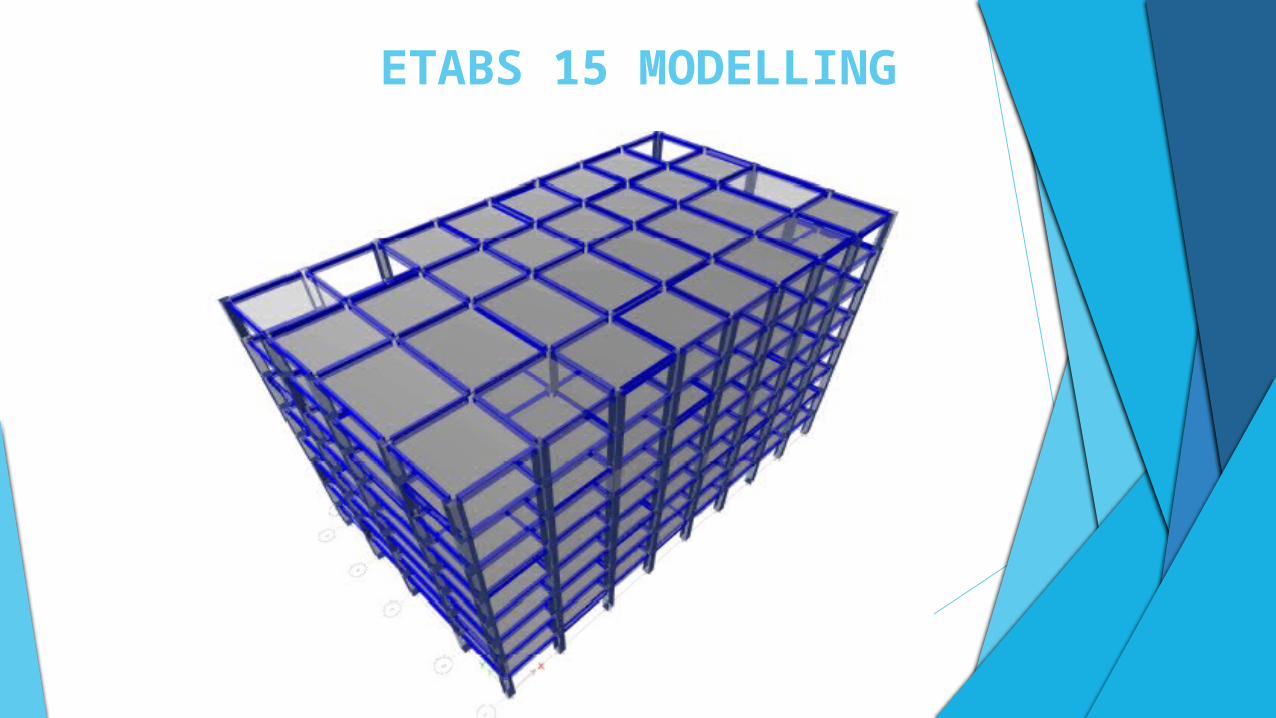
ETABS 15 MODELLING
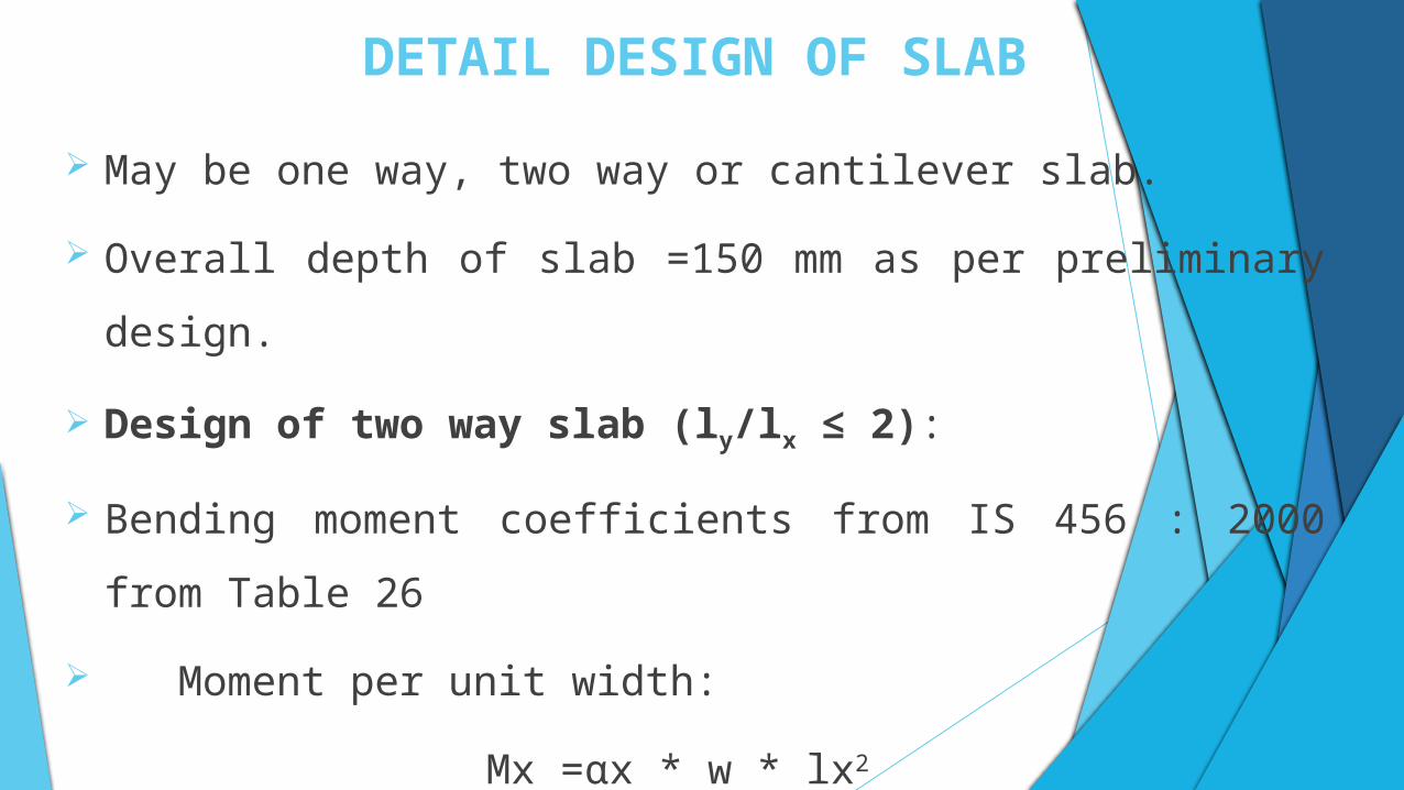
DETAIL DESIGN OF SLAB
May be one way, two way or cantilever slab.
Overall depth of slab =150 mm as per preliminary design.
Design of two way slab (ly/lx ≤ 2):
Bending moment coefficients from IS 456 : 2000 from Table 26
Moment per unit width:
Mx =αx * w * lx2
My =αy * w * lx2
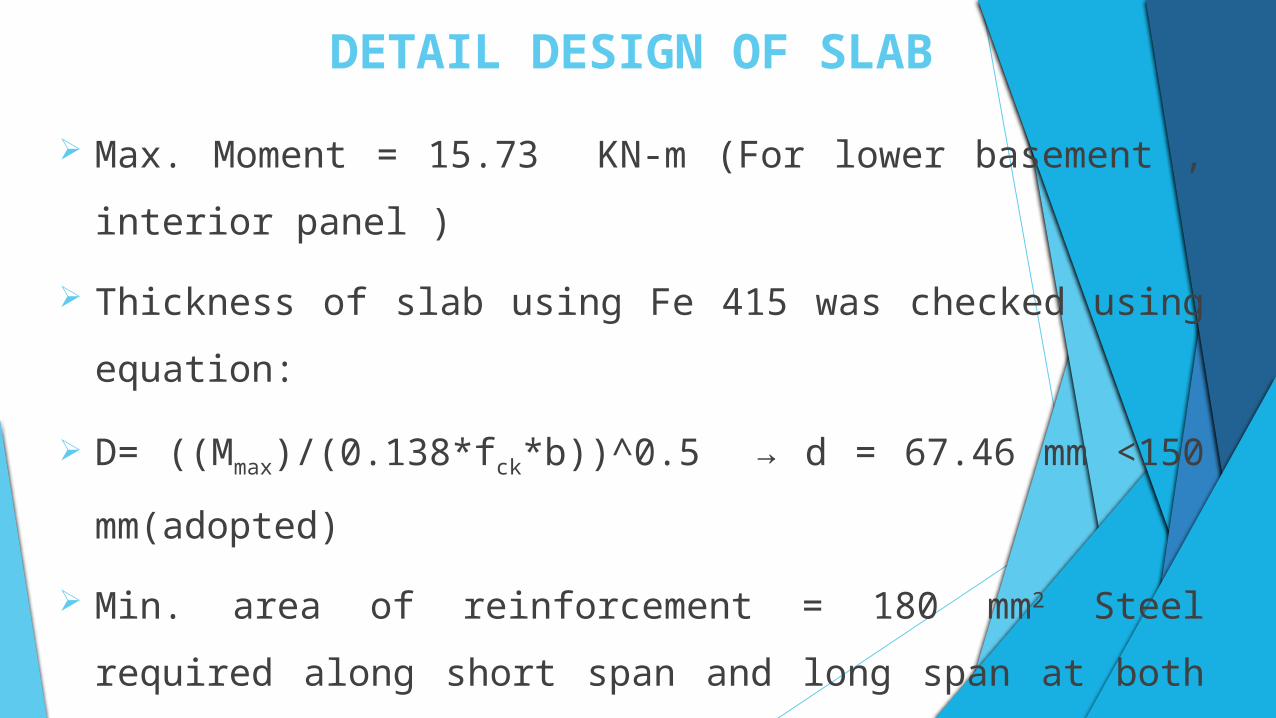
DETAIL DESIGN OF SLAB
Max. Moment = 15.73 KN-m (For lower basement , interior panel )
Thickness of slab using Fe 415 was checked using equation:
D= ((Mmax)/(0.138*fck*b))^0.5 → d = 67.46 mm <150 mm(adopted)
Min. area of reinforcement = 180 mm2 Steel required along short span and
long span at both support and mid span was determined using the
equation:
B.M.=0.87*fy*Ast*(d-fy*Ast/fck*b)
DETAIL DESIGN OF SLAB
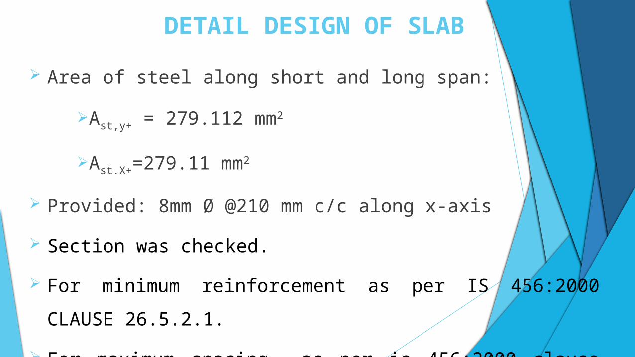
Area of steel along short and long span:
Ast,y+ = 279.112 mm2
Ast.X+=279.11 mm2
Provided: 8mm Ø @210 mm c/c along x-axis
Section was checked.
For minimum reinforcement as per IS 456:2000 CLAUSE 26.5.2.1.
For maximum spacing as per is 456:2000 clause 26.3.3.B.1
DETAIL DESIGN OF SLAB
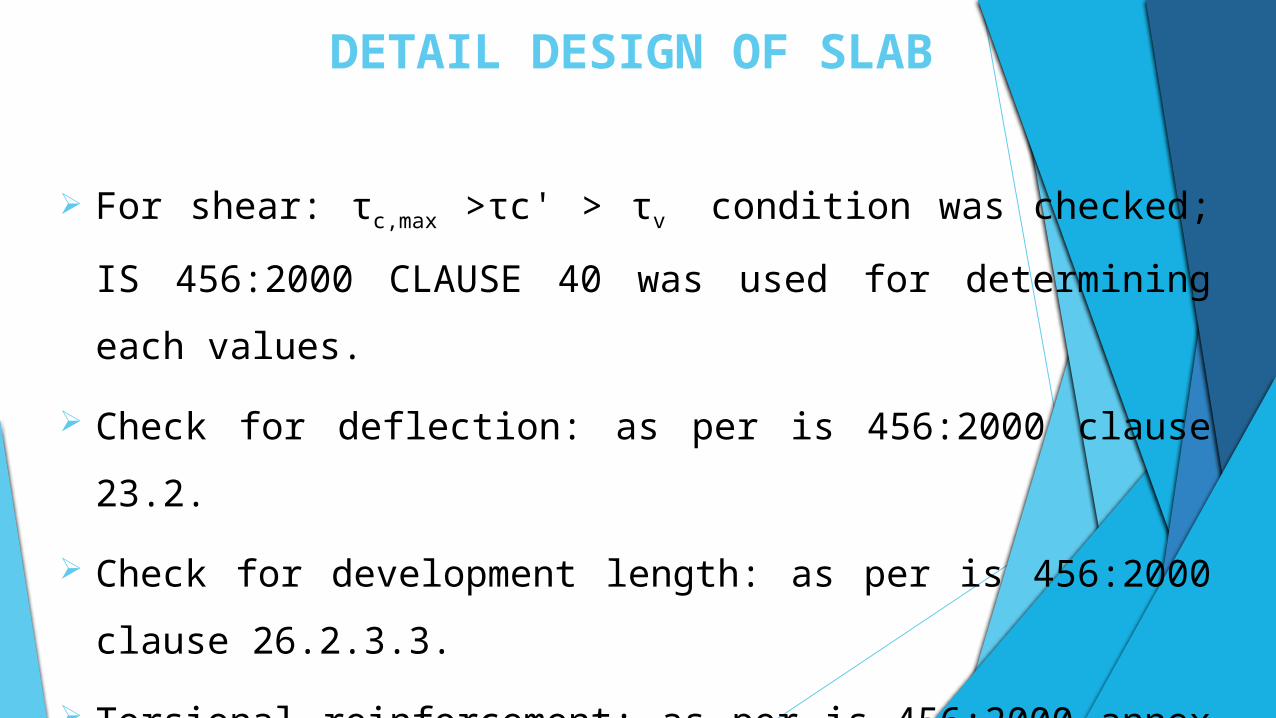
For shear: τc,max >τc' > τv condition was checked; IS 456:2000 CLAUSE
40 was used for determining each values.
Check for deflection: as per is 456:2000 clause 23.2.
Check for development length: as per is 456:2000 clause 26.2.3.3.
Torsional reinforcement: as per is 456:2000 annex d (d-1.8).
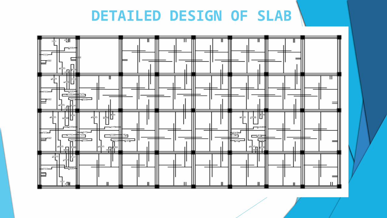
DETAILED DESIGN OF SLAB
DETAIL DESIGN OF BEAM
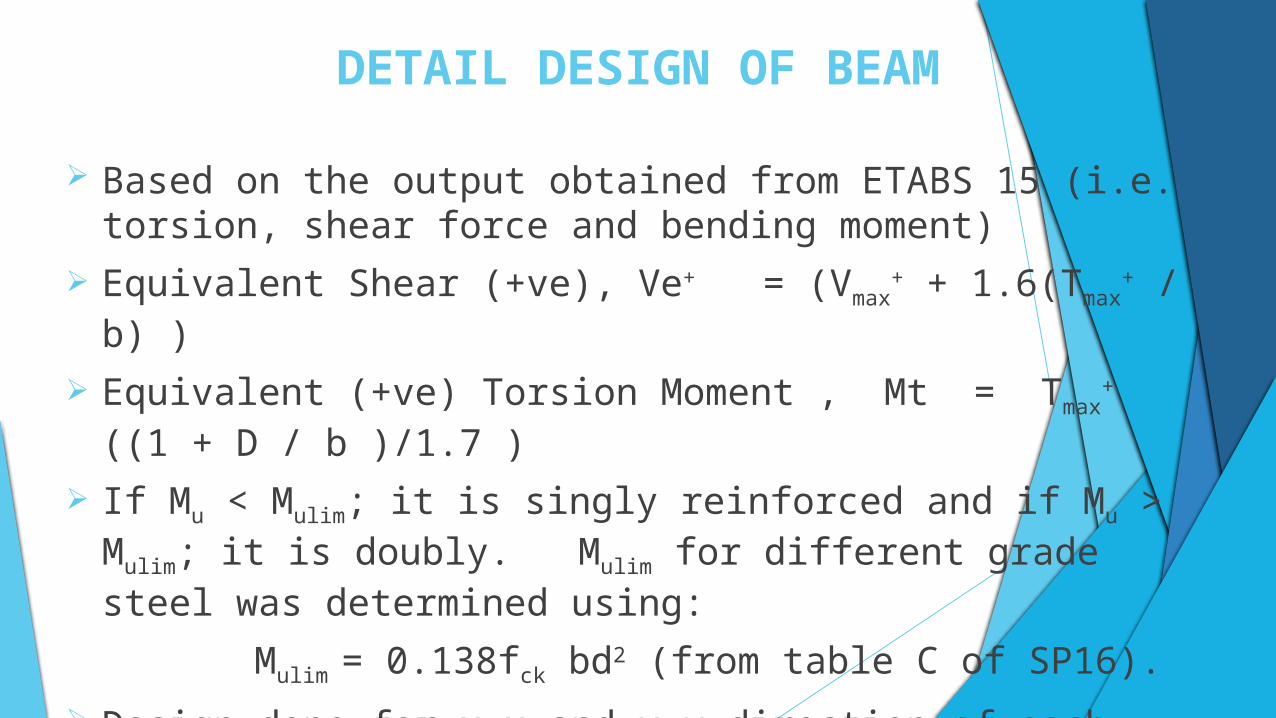
Based on the output obtained from ETABS 15 (i.e. torsion, shear force and bending moment)
Equivalent Shear (+ve), Ve+ = (Vmax+ + 1.6(Tmax
+ / b) )
Equivalent (+ve) Torsion Moment , Mt = Tmax+ ((1 + D / b )/1.7 )
If Mu < Mulim; it is singly reinforced and if Mu > Mulim; it is doubly. Mulim for different grade steel was determined using:
Mulim = 0.138fck bd2 (from table C of SP16).
Design done for x-x and y-y direction of each floor beam.
DETAIL DESIGN OF BEAM
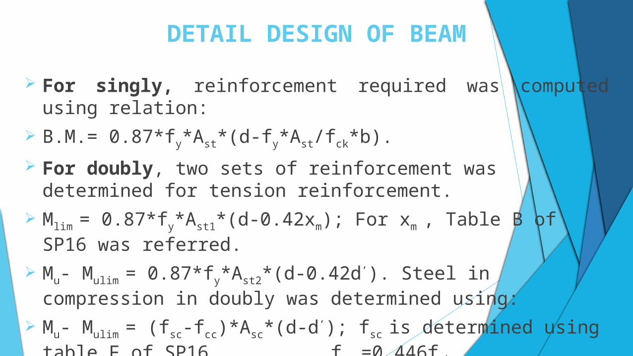
For singly, reinforcement required was computed using relation:
B.M.= 0.87*fy*Ast*(d-fy*Ast/fck*b).
For doubly, two sets of reinforcement was determined for tension reinforcement.
Mlim = 0.87*fy*Ast1*(d-0.42xm); For xm , Table B of SP16 was referred.
Mu- Mulim = 0.87*fy*Ast2*(d-0.42d’). Steel in compression in doubly was determined using:
Mu- Mulim = (fsc-fcc)*Asc*(d-d’); fsc is determined using table F of SP16, fcc
=0.446fck
DETAIL DESIGN OF BEAM
The section so designed was checked for minimum reinforcement and
maximum reinforcement as per IS 456:2000 clause 26.5.1.
At least 2 nos. Reinforcement was made run through out beam for ductility.
Check for development length as per IS 456:2000 clause 26.2.3.3.
DETAIL DESIGN OF BEAM
Check for shear reinforcement:
As per IS 456:2000 clause 40.
Minimum shear reinforcement as per IS 456:2000 clause 26.5.1.6.
Maximum spacing as per IS 456:2000 clause 26.5.1.5 (0.75d or 300 mm).
For ductility, maximum spacing of stirrup is d/4 or 8ϕ over 2d at either
end.
Check for deflection as per IS 456:2000 clause 23.2.1.
DETAILED DESIGN OF BEAM
Member
SectionSteel
Reinforcement Area Bars Area
PositionPosition Required
ProvidedProvided
Ar (mm2) Ap (mm2)
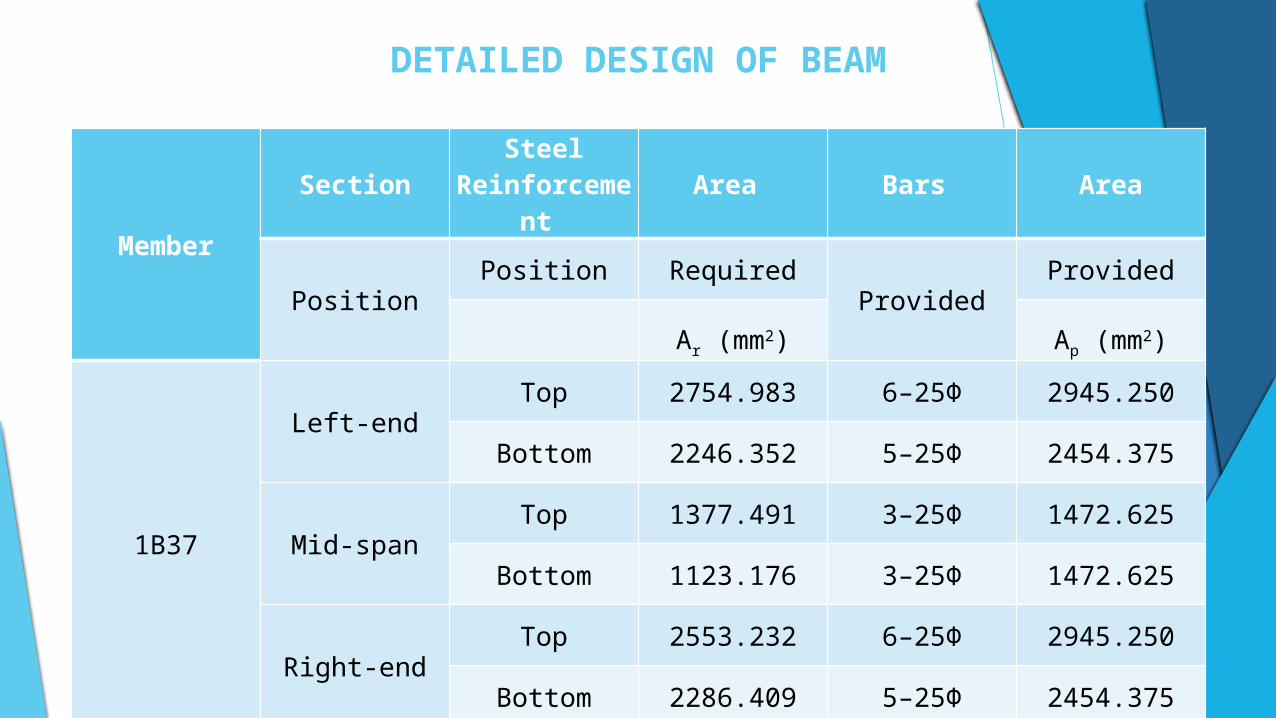
1B37
Left-endTop 2754.983 6–25Φ 2945.250
Bottom 2246.352 5–25Φ 2454.375
Mid-spanTop 1377.491 3–25Φ 1472.625
Bottom 1123.176 3–25Φ 1472.625
Right-endTop 2553.232 6–25Φ 2945.250
Bottom 2286.409 5–25Φ 2454.375

DETAILED DESIGN OF BEAM
Member
SectionSteel
Reinforcement Area Bars Area
PositionPosition Required
ProvidedProvided
Ar (mm2) Ap (mm2)
1B41
Left-endTop 2580.061 6–25Φ 2945.250
Bottom 2134.903 5–25Φ 2454.375
Mid-spanTop 1290.031 3–25Φ 1472.625
Bottom 1067.452 3–25Φ 1472.625
Right-endTop 2485.868 6–25Φ 2945.250
Bottom 2227.545 5–25Φ 2454.375
DETAILED DESIGN OF COLUMN
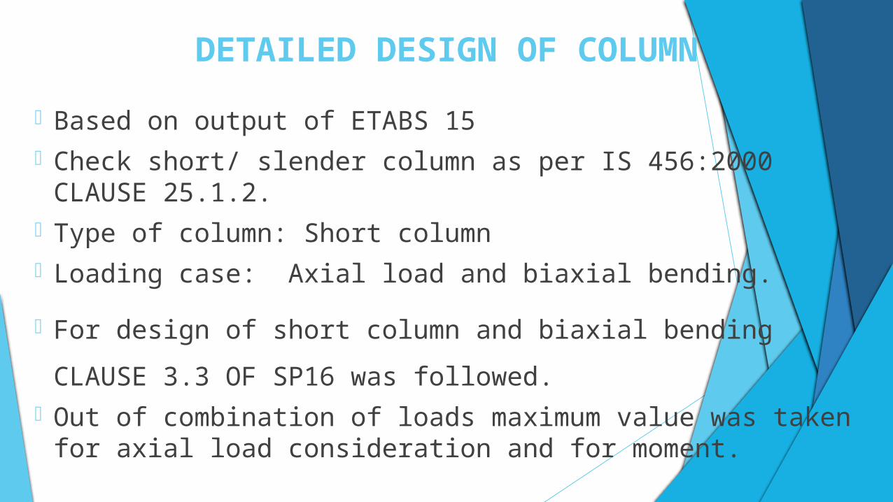
• Based on output of ETABS 15• Check short/ slender column as per IS 456:2000 CLAUSE 25.1.2.• Type of column: Short column• Loading case: Axial load and biaxial bending.
• For design of short column and biaxial bending CLAUSE 3.3 OF SP16 was
followed.• Out of combination of loads maximum value was taken for axial load
consideration and for moment.
DETAILED DESIGN OF COLUMN CONTINUED..
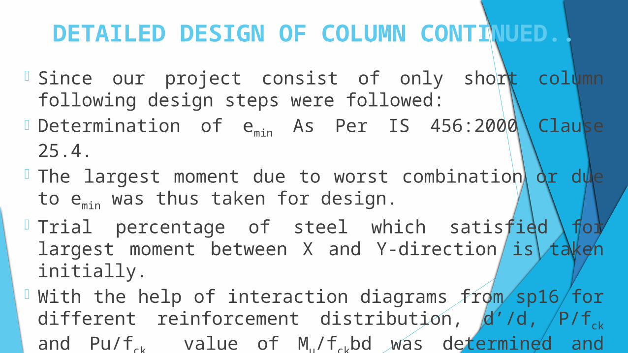
• Since our project consist of only short column following design steps were followed:
• Determination of emin As Per IS 456:2000 Clause 25.4.
• The largest moment due to worst combination or due to emin was thus taken for design.
• Trial percentage of steel which satisfied for largest moment between X and Y-direction is taken initially.
• With the help of interaction diagrams from sp16 for different reinforcement distribution, d’/d, P/fck and Pu/fck value of Mu/fckbd was determined and clause 39.6 of is 456:2000 was checked.
DETAILED DESIGN OF COLUMN CONTINUED..
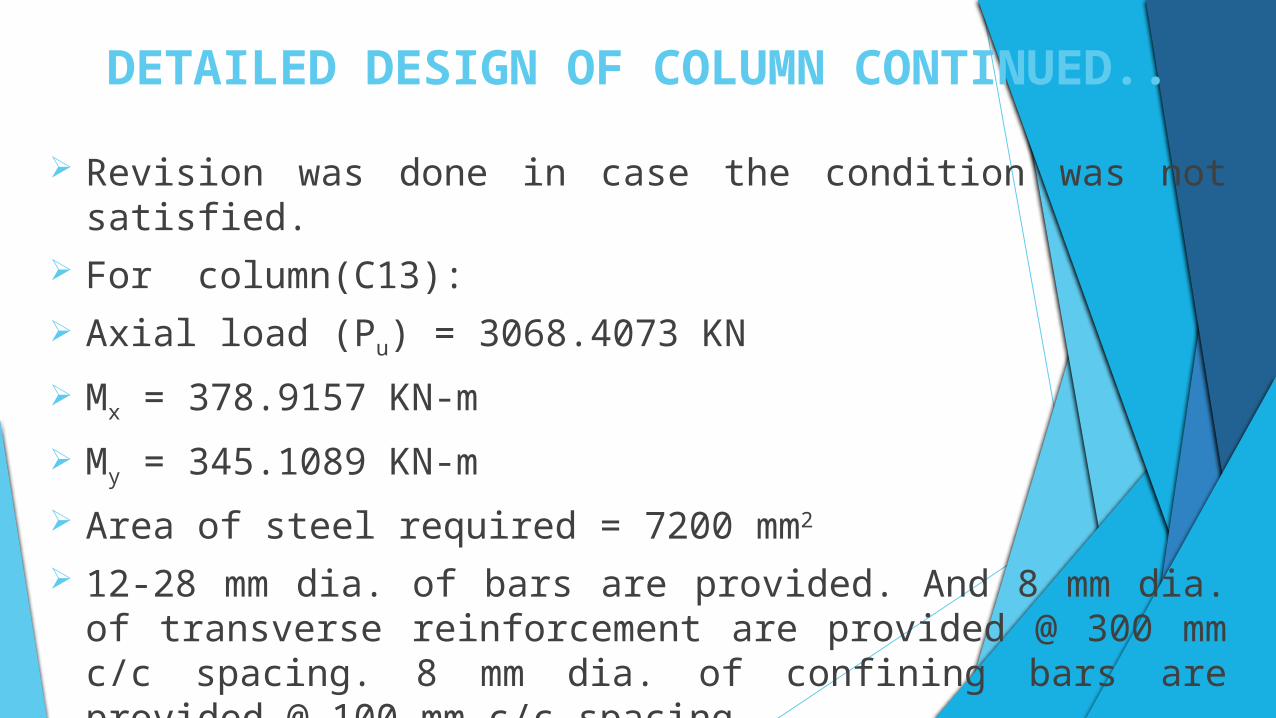
Revision was done in case the condition was not satisfied. For column(C13):
Axial load (Pu) = 3068.4073 KN
Mx = 378.9157 KN-m
My = 345.1089 KN-m
Area of steel required = 7200 mm2 12-28 mm dia. of bars are provided. And 8 mm dia. of transverse
reinforcement are provided @ 300 mm c/c spacing. 8 mm dia. of confining bars are provided @ 100 mm c/c spacing.
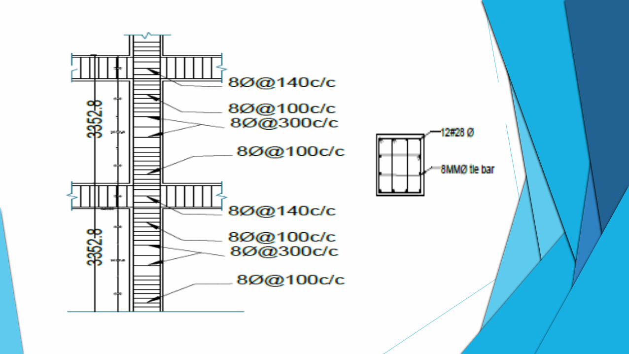
DETAILED DESIGN OF COLUMN CONTD…
DETAIL DESIGN OF FOUNDATION
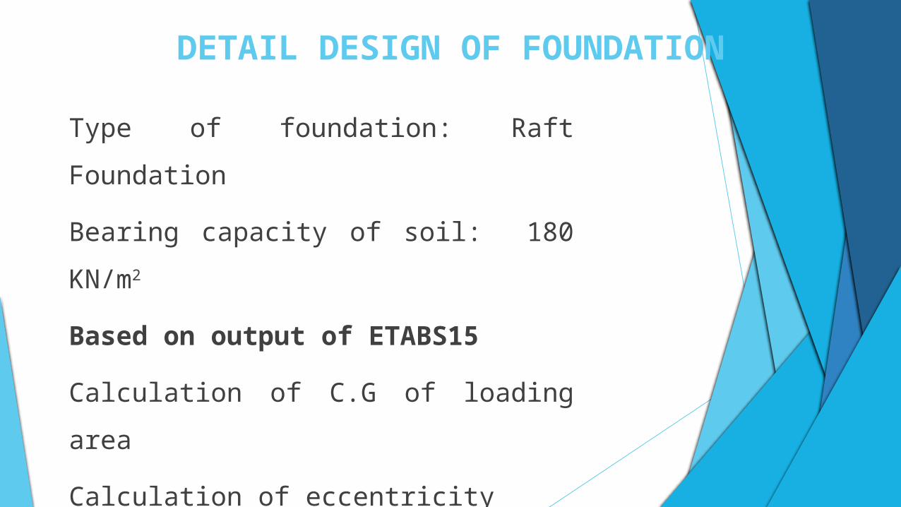
Type of foundation: Raft Foundation
Bearing capacity of soil: 180 KN/m2
Based on output of ETABS15
Calculation of C.G of loading area
Calculation of eccentricity
ex=-0.011 m & ey=0.362 m
DETAIL DESIGN OF FOUNDATION
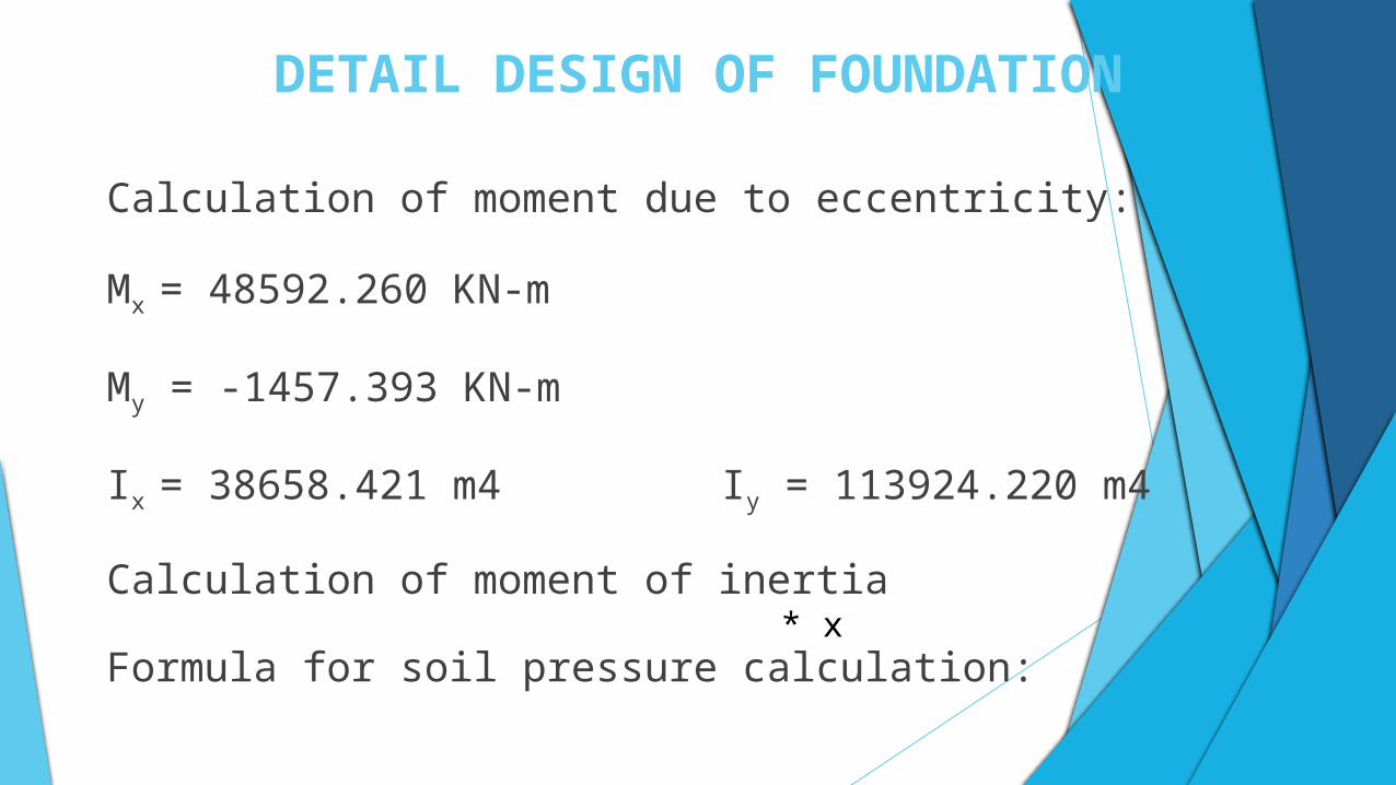
Calculation of moment due to eccentricity:
Mx = 48592.260 KN-m
My = -1457.393 KN-m
Ix = 38658.421 m4 Iy = 113924.220 m4
Calculation of moment of inertia
Formula for soil pressure calculation: * x
DETAIL DESIGN OF FOUNDATION
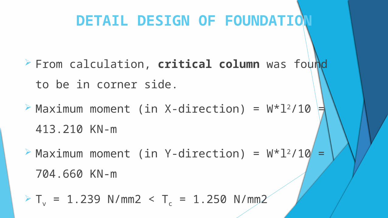
From calculation, critical column was found to be in corner side.
Maximum moment (in X-direction) = W*l2/10 = 413.210 KN-m
Maximum moment (in Y-direction) = W*l2/10 = 704.660 KN-m
Tv = 1.239 N/mm2 < Tc = 1.250 N/mm2
DETAIL DESIGN OF FOUNDATION
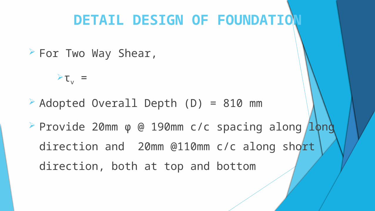
For Two Way Shear,
τv =
Adopted Overall Depth (D) = 810 mm
Provide 20mm φ @ 190mm c/c spacing along long direction and
20mm @110mm c/c along short direction, both at top and bottom
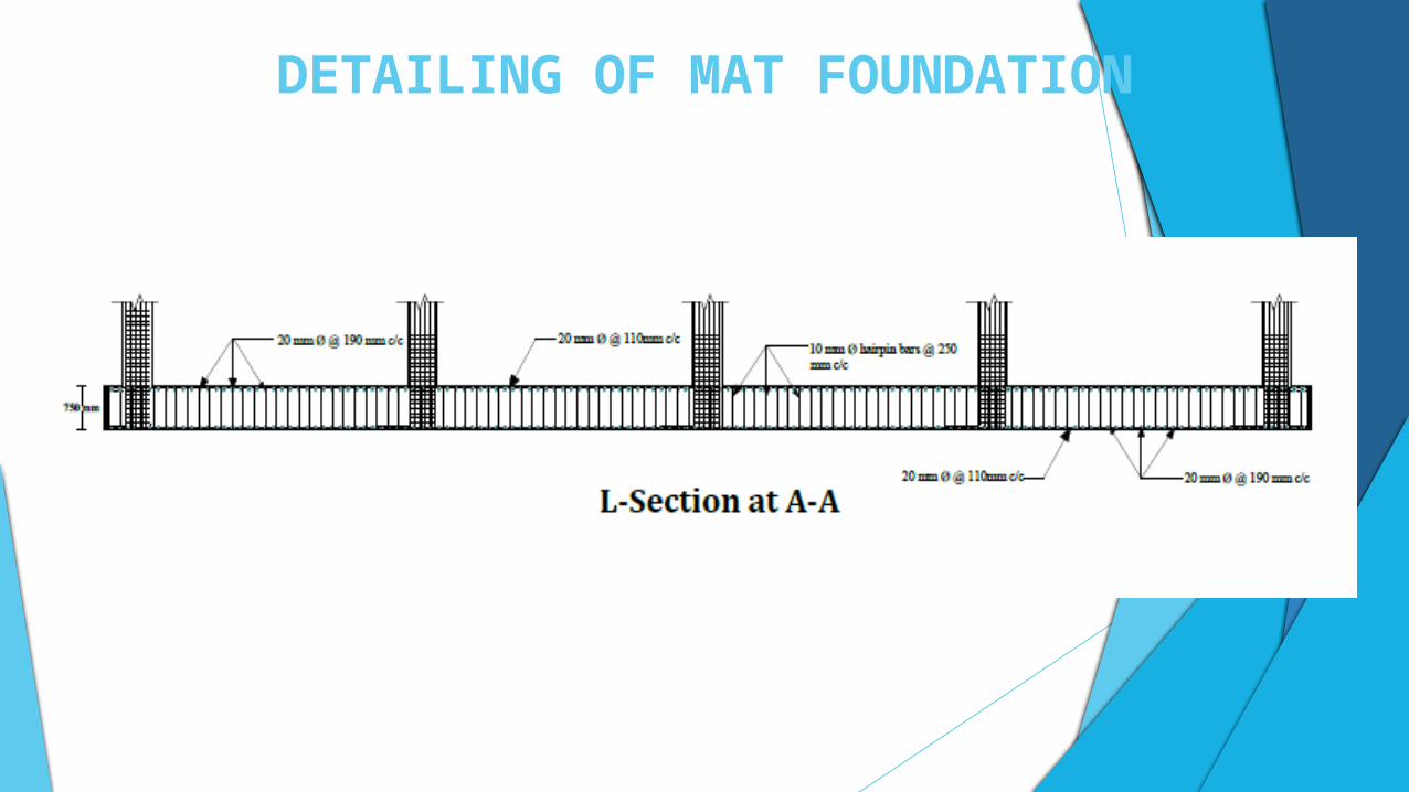
DETAILING OF MAT FOUNDATION
DETAILED DESIGN OF STAIRCASE
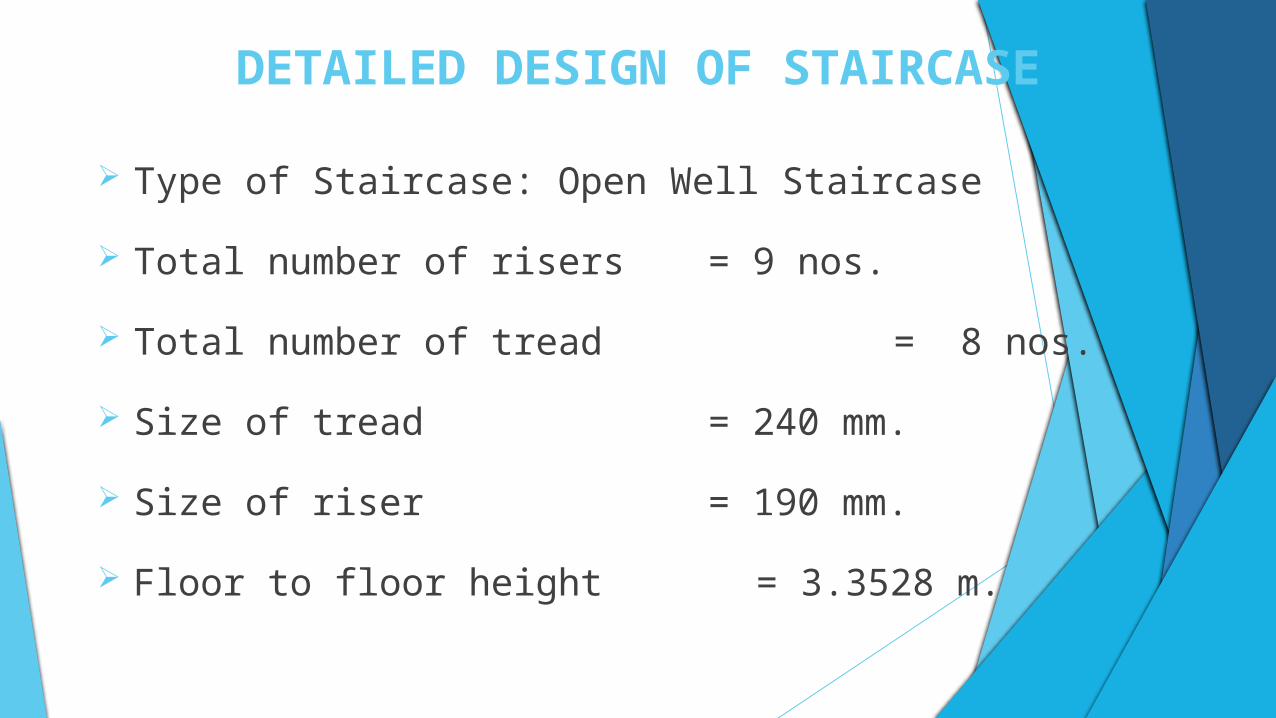
Type of Staircase: Open Well Staircase
Total number of risers = 9 nos.
Total number of tread = 8 nos.
Size of tread = 240 mm.
Size of riser = 190 mm.
Floor to floor height = 3.3528 m.
DETAILED DESIGN OF STAIRCASE
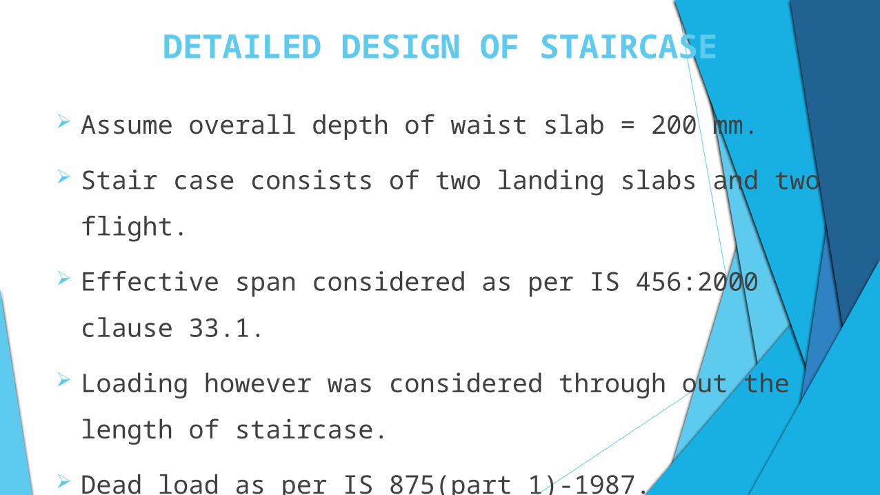
Assume overall depth of waist slab = 200 mm.
Stair case consists of two landing slabs and two flight.
Effective span considered as per IS 456:2000 clause 33.1.
Loading however was considered through out the length of staircase.
Dead load as per IS 875(part 1)-1987.
Live load as per IS 875(part 2)-5 KN/m2
DETAILED DESIGN OF STAIRCASE
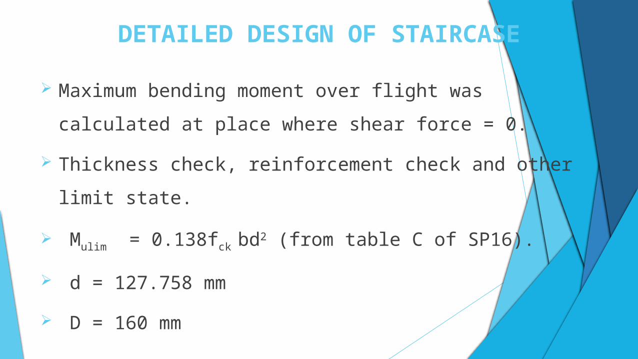
Maximum bending moment over flight was calculated at place where
shear force = 0.
Thickness check, reinforcement check and other limit state.
Mulim = 0.138fck bd2 (from table C of SP16).
d = 127.758 mm
D = 160 mm
DETAILED DESIGN OF STAIRCASE
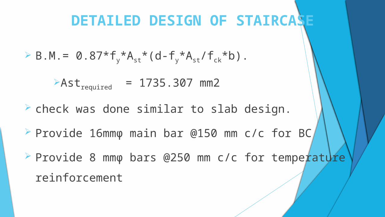
B.M.= 0.87*fy*Ast*(d-fy*Ast/fck*b).
Astrequired = 1735.307 mm2
check was done similar to slab design.
Provide 16mmϕ main bar @150 mm c/c for BC
Provide 8 mmϕ bars @250 mm c/c for temperature reinforcement
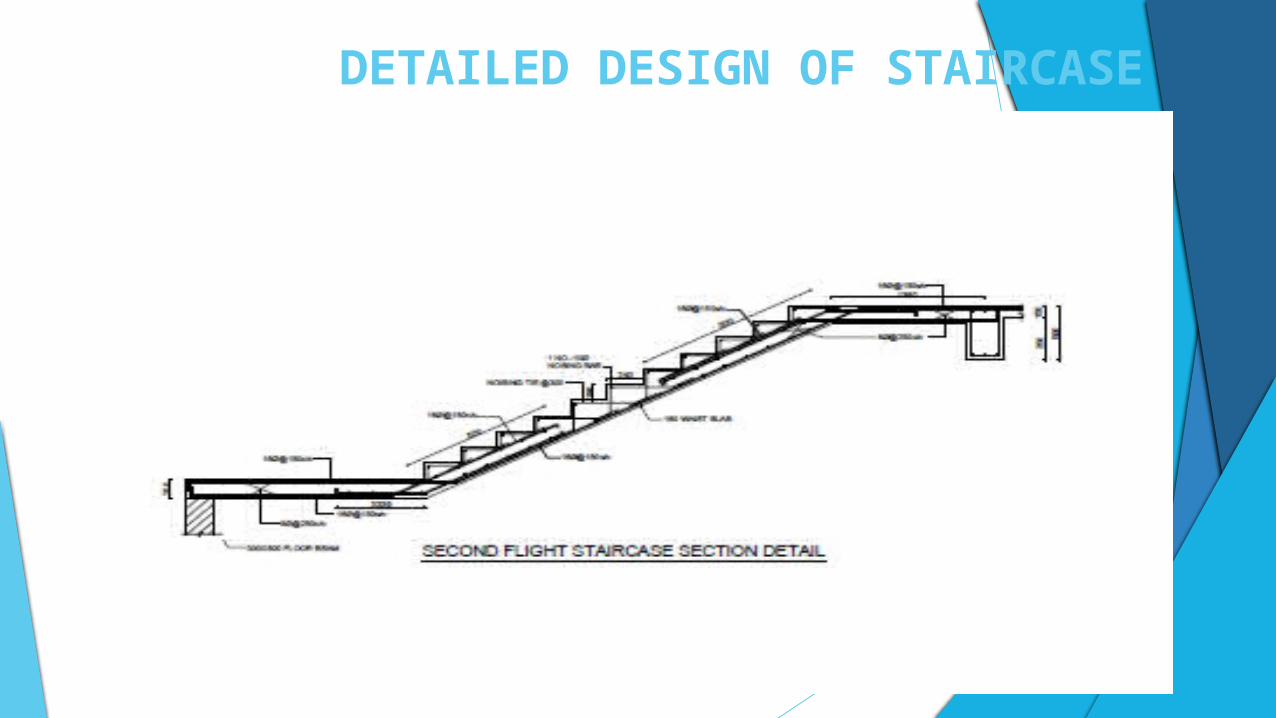
DETAILED DESIGN OF STAIRCASE
RESULT
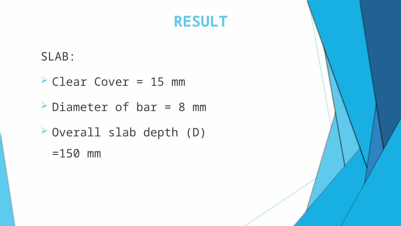
SLAB:
Clear Cover = 15 mm
Diameter of bar = 8 mm
Overall slab depth (D) =150 mm
RESULT
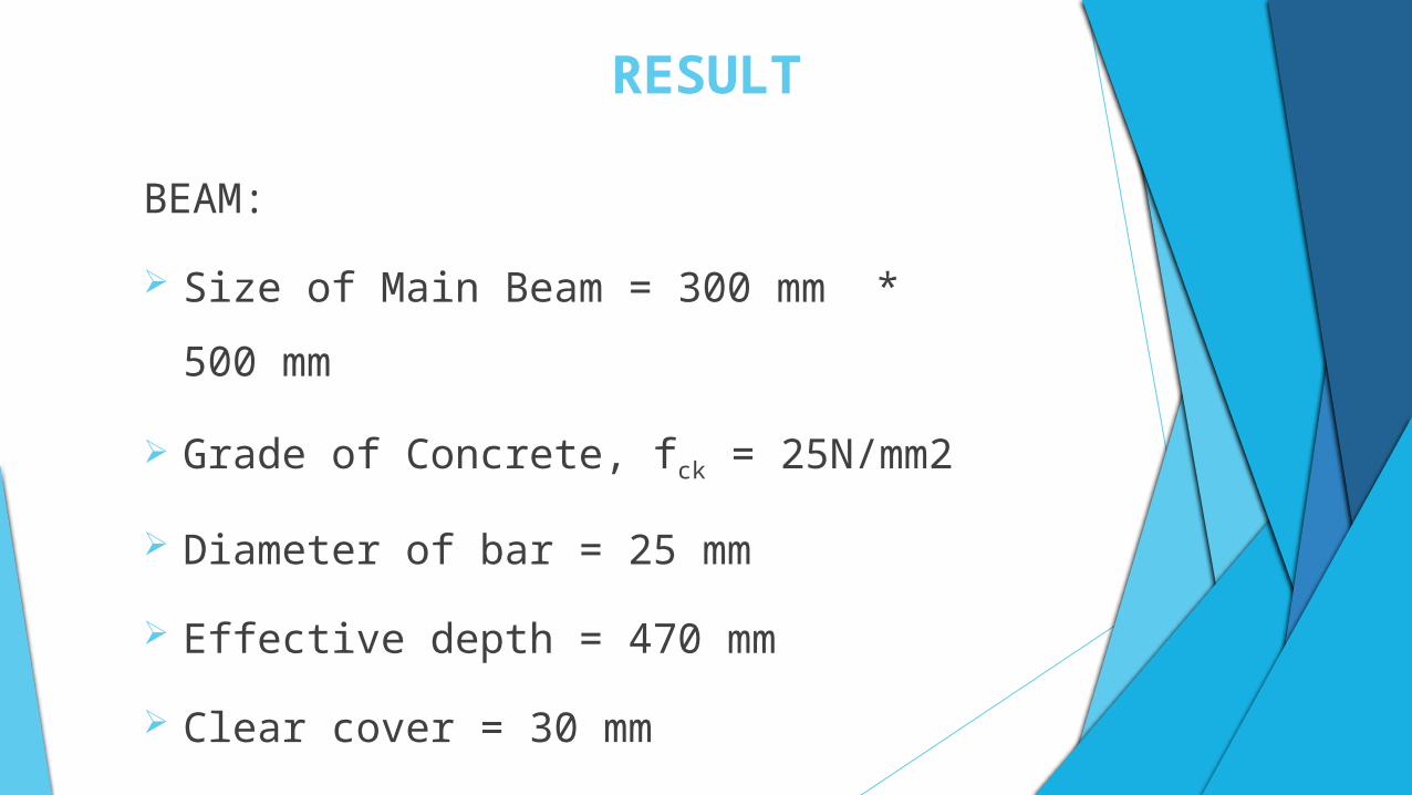
BEAM:
Size of Main Beam = 300 mm * 500 mm
Grade of Concrete, fck = 25N/mm2
Diameter of bar = 25 mm
Effective depth = 470 mm
Clear cover = 30 mm
RESULT
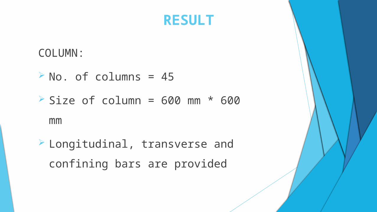
COLUMN:
No. of columns = 45
Size of column = 600 mm * 600 mm
Longitudinal, transverse and confining bars are
provided
RESULT
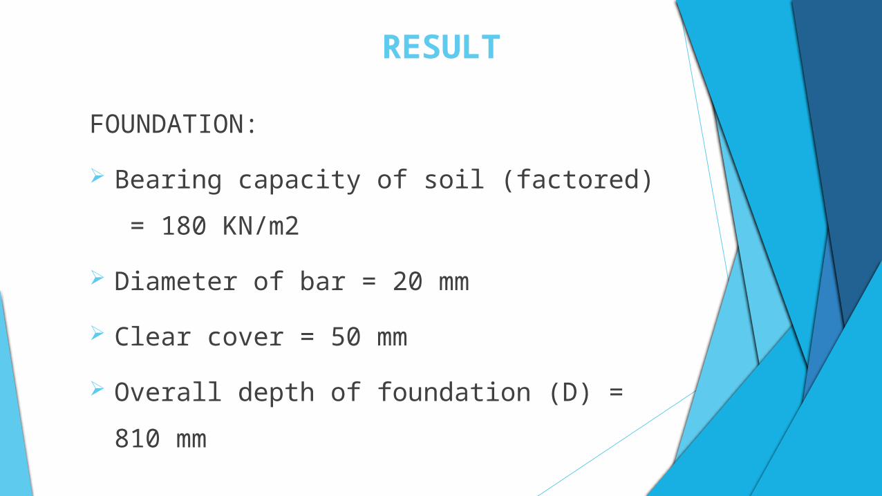
FOUNDATION:
Bearing capacity of soil (factored) = 180 KN/m2
Diameter of bar = 20 mm
Clear cover = 50 mm
Overall depth of foundation (D) = 810 mm
RESULT
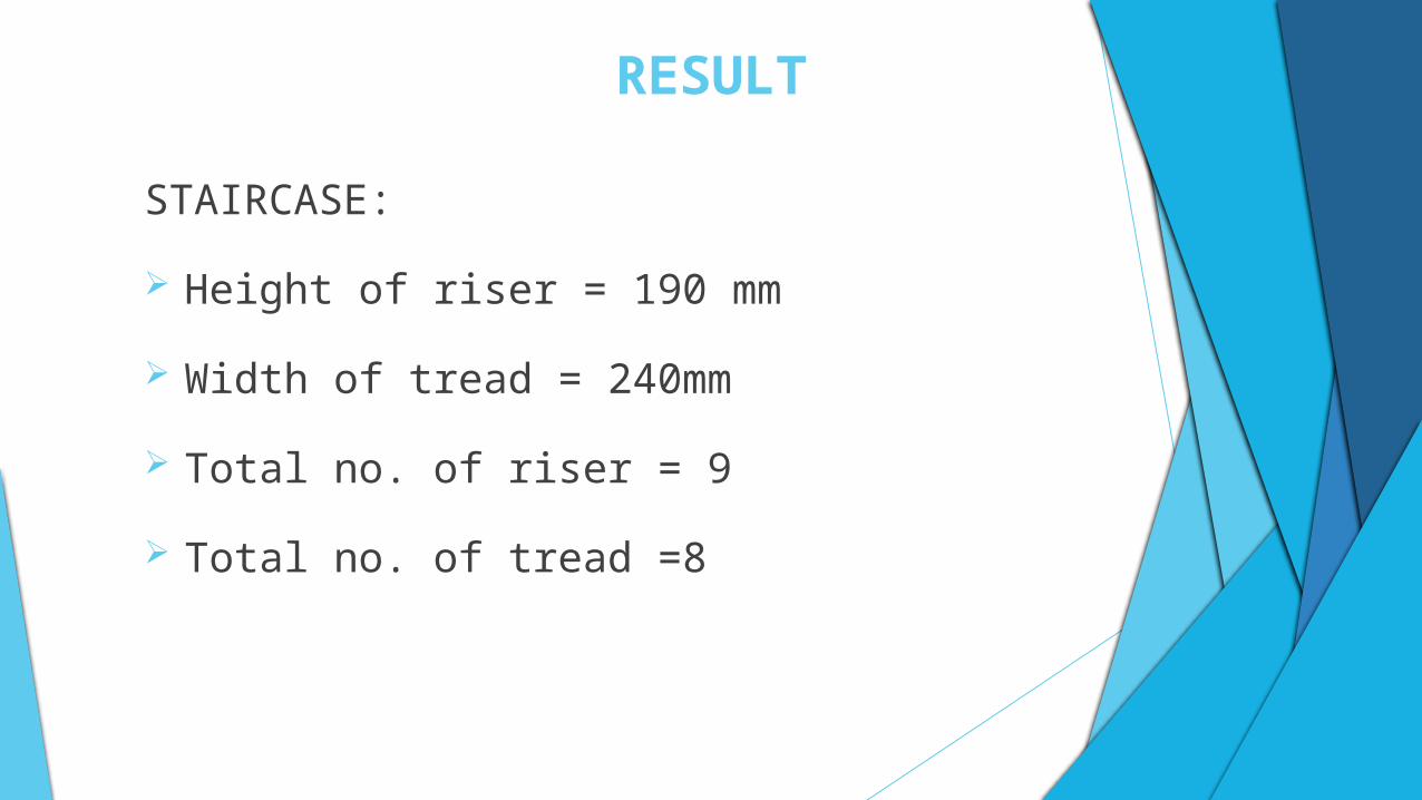
STAIRCASE:
Height of riser = 190 mm
Width of tread = 240mm
Total no. of riser = 9
Total no. of tread =8
CONCLUSION
The purpose of this project, was purely academic oriented, we have
made every effort to make it feasible for the real construction.
Structural analysis and design of eight storied building was done.
From this project work, we gained the opportunity to acquire
knowledge of using professional software called ETABS 15 for the
analysis and design of the structure.
CONCLUSION
This project work also enables us to use different design codes
whenever required in the design procedure.
This project work has provided the opportunity to learn the theory of
ductile detailing, which is one of the significant part of seismic
structural design.
After completion of this project work, our team member individually
could design the similar type of structure an structural elements.

THANK YOU..