final report on 3d modelling of cormorant helicopter for
TRANSCRIPT
FINAL REPORT ON 3D MODELLING OF
CORMORANT HELICOPTER
FOR THE 3D DATA ACQUISITION AND
MODELLING SERVICES PROJECT
by:
Ray M. Obidowski
Array Systems Computing Inc. 1120 Finch Avenue West 7th Floor
Toronto, ON M3J 3H7
Project Manager: Rajesh Jha
(416) 736-0900 x269
PWGSC Contract No.: W7711-017752/001/TOR Call-Up No.: 7752-04
Report No.: ASC_DAMS_006
On behalf of Defense R&D Canada
DRDC Toronto Scientific Authority Pierre Meunier
Simulation and Modeling in Acquisition, Rehearsal and Training (SMART) Section
(416) 635-2093
October 20, 2003
The scientific or technical validity of this Contract Report is entirely the responsibility of the contractor and the contents do not necessarily have the approval or endorsement of Defence R&D Canada.
DRDC Toronto Contractor Report
DRDC Toronto CR 2003-148
2003-10-20
FINAL REPORT ON 3D MODELLING OF
CORMORANT HELICOPTER
FOR THE 3D DATA ACQUISITION AND
MODELLING SERVICES PROJECT
Author: ________________________ ______________ Ray M. Obidowski Date Project Manager: ________________________ ______________ Rajesh Jha Date
© Her Majesty the Queen as represented by the Minister of National Defence, 2003
© Sa majesté la reine, représentée par le ministre de la Défense nationale, 2003

FINAL REPORT ON 3D MODELLING OF
CORMORANT HELICOPTER
FOR THE 3D DATA ACQUISITION AND
MODELLING SERVICES PROJECT
Revision History
Version Date Revised By Description 1.0
October 20, 2003
RO Initial release.

THIS PAGE INTENTIONALLY LEFT BLANK

Abstract This report describes the production of three graphics models of the Cormorant helicopter processed from laser scan data for both the helicopter exterior and cockpit interior. These Polygon and Non-Rational Uniform B-Spline (NURBS) surface models are scalable, and logically arranged in groups and/or layers. They also represent graphically the range of motions in the cockpit of the cyclics, collectives, pedals, and seats.
An external mean accuracy of less than 1 millimetre (mm), and standard error of 4-6 mm for modelled areas of interest was verified with respect to the original data. An interior mean accuracy of less than 1 mm and standard error of 2-3 mm for modelled areas of interest was similarly verified. This accuracy is consistent and compatible with the accuracy of the laser scanners and their data.

THIS PAGE INTENTIONALLY LEFT BLANK
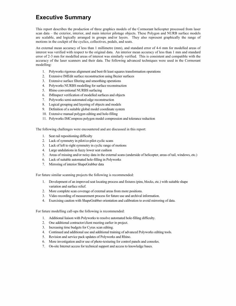
Executive Summary
This report describes the production of three graphics models of the Cormorant helicopter processed from laser scan data – the exterior, interior, and main interior pilotage objects. These Polygon and NURB surface models are scalable, and logically arranged in groups and/or layers. They also represent graphically the range of motions in the cockpit of the cyclics, collectives, pedals, and seats.
An external mean accuracy of less than 1 millimetre (mm), and standard error of 4-6 mm for modelled areas of interest was verified with respect to the original data. An interior mean accuracy of less than 1 mm and standard error of 2-3 mm for modelled areas of interest was similarly verified. This is consistent and compatible with the accuracy of the laser scanners and their data. The following advanced techniques were used in the Cormorant modelling:
1. Polyworks rigorous alignment and best-fit least squares transformation operations 2. Extensive IMEdit surface reconstruction using Bezier surfaces 3. Extensive surface filtering and smoothing operations 4. Polyworks NURBS modelling for surface reconstruction 5. Rhino conventional NURBS surfacing 6. IMInspect verification of modelled surfaces and objects 7. Polyworks semi-automated edge reconstruction 8. Logical grouping and layering of objects and models 9. Definition of a suitable global model coordinate system 10. Extensive manual polygon editing and hole-filling 11. Polyworks IMCompress polygon model compression and tolerance reduction
The following challenges were encountered and are discussed in this report:
1. Seat rail repositioning difficulty 2. Lack of symmetry in pilot/co-pilot cyclic scans 3. Lack of left to right symmetry in cyclic range of motions 4. Large undulations in fuzzy lower seat cushion 5. Areas of missing and/or noisy data in the external scans (underside of helicopter, areas of tail, windows, etc.) 6. Lack of suitable automated hole-filling in Polyworks 7. Mirroring of interior ShapeGrabber data
For future similar scanning projects the following is recommended:
1. Development of an improved seat locating process and fixtures (pins, blocks, etc.) with suitable shape variation and surface relief.
2. More complete scan coverage of external areas from more positions. 3. Video recording of measurement process for future use and archival information. 4. Exercising caution with ShapeGrabber orientation and calibration to avoid mirroring of data.
For future modelling call-ups the following is recommended:
1. Additional liaison with Polyworks to resolve automated hole-filling difficulty. 2. One additional contractor/client meeting earlier in project. 3. Increasing time budgets for Cyrax scan editing. 4. Continued and additional use and additional training of advanced Polyworks editing tools. 5. Revision and service pack updates of Polyworks and Rhino. 6. More investigation and/or use of photo-texturing for control panels and consoles. 7. On-site Internet access for technical support and access to knowledge bases.
Final Report on 3D Modeling of Cormorant Helicopter Standing Offer Call-Up #4
ASC_DAMS_006, Version 1.0, October 20, 2003
Array Systems Computing Inc.
Printed on October 20, 2003 Page ii
Table of Contents 1 INTRODUCTION AND BACKGROUND......................................................................................................... 1
2 DETAILS AND RESULTS OF INDIVIDUAL TASKS.................................................................................... 3
2.1 Interior Graphics Modelling of Cormorant Helicopter....................................................................... 3 2.1.1 Alignment and Polygonization of Data............................................................................................... 3 2.1.2 Transformation of Data to Global Model Coordinate System ........................................................... 5 2.1.3 Alignment of Seats and Seat Rails In Cockpit.................................................................................... 7 2.1.4 Interior Surfacing and Range of Motion of Key Objects Using Rhino.............................................. 8 2.1.4.1 Consoles and Control Panels ............................................................................................................... 9 2.1.4.2 Pedals ................................................................................................................................................. 10 2.1.4.3 Collectives and Cyclics (Control Sticks) .......................................................................................... 11 2.1.4.4 Seats and Seat Cushions .................................................................................................................... 13 2.1.5 Verification of Interior Objects ......................................................................................................... 14 2.1.5.1 Consoles and Control Panels ............................................................................................................. 15 2.1.5.2 Pedals ................................................................................................................................................. 16 2.1.5.3 Collectives ......................................................................................................................................... 17 2.1.5.4 Cyclics................................................................................................................................................ 18 2.1.5.5 Seats and Seat Cushions .................................................................................................................... 19 2.1.5.6 Other Control Panels ......................................................................................................................... 20 2.2 Exterior Graphics Modelling of Cormorant Helicopter.................................................................... 22 2.2.1 Alignment and Polygonization of Data............................................................................................. 22 2.2.2 Advanced Polygon Editing and Reconstruction ............................................................................... 23 2.2.2.1 Edge Reconstruction.......................................................................................................................... 24 2.2.2.2 NURBS Modelling In Polyworks ..................................................................................................... 25 2.2.2.3 Filtering and Smoothing of Data, Hole Filling ................................................................................. 25 2.2.2.4 Modelling of External Fixtures and Objects ..................................................................................... 26 2.2.3 Transformation to Global Model Coordinate System....................................................................... 26 2.2.4 Verification of External Model and Fixtures .................................................................................... 28
3 FINAL MODEL AND DELIVERABLES ........................................................................................................ 33
3.1 Exterior Polygon Model .................................................................................................................... 33 3.2 Interior Polygon Model ..................................................................................................................... 34 3.3 Interior Rhino NURBS Model .......................................................................................................... 34
4 SUMMARY OF FINDINGS AND RECOMMENDATIONS ........................................................................ 36
Final Report on 3D Modeling of Cormorant Helicopter Standing Offer Call-Up #4
ASC_DAMS_006, Version 1.0, October 20, 2003
Array Systems Computing Inc.
Printed on October 20, 2003 Page iii
List of Figures Figure 1. Exterior Image of Cormorant Helicopter ......................................................................................................... 1 Figure 2. Interior of Cormorant Helicopter...................................................................................................................... 2 Figure 3. Point Cloud Scans of Aircraft Cockpit Interior ............................................................................................... 3 Figure 4. Confirmation of Mirroring of Data from ShapeGrabber Scanner ................................................................... 4 Figure 5. Polygon Representation and Functional Groups for Aircraft Cockpit Interior ............................................... 5 Figure 6. Definition of Global Model Coordinate System.............................................................................................. 6 Figure 7. Detail of Seat and Seat Rail Positioning on Cockpit Floor.............................................................................. 8 Figure 8. Console and Control Panel Objects.................................................................................................................. 9 Figure 9. Control Pedal Objects ..................................................................................................................................... 10 Figure 10. Cyclic Stick Objects ..................................................................................................................................... 11 Figure 11. Asymmetrical Cyclic Range of Motion Noted ............................................................................................ 12 Figure 12. Seat and Seat Cushion Objects ..................................................................................................................... 13 Figure 13. Lower Seat Cushion Irregular Shape ........................................................................................................... 14 Figure 14. Error Map of Console and Control Panels (mm) ......................................................................................... 15 Figure 15. Error Maps of Control Pedals (mm)............................................................................................................. 16 Figure 16. Error Maps of Collectives (Point Clouds) (mm).......................................................................................... 17 Figure 17. Error Maps of Cyclics (mm)......................................................................................................................... 18 Figure 18. Error Maps of Seats and Seat Cushions (mm) ............................................................................................. 19 Figure 19. Error Map for Upper Control Panel and Consoles (mm)............................................................................. 20 Figure 20. Error Map for Back Control Panels (mm).................................................................................................... 21 Figure 21. Point Cloud Scan Model of Shell ................................................................................................................. 22 Figure 22. Unedited Polygon Model of Exterior Shell.................................................................................................. 23 Figure 23. Example of Polyworks Edge Reconstruction Using IMEdit’s Tools.......................................................... 24 Figure 24. Example of Polyworks NURBS Curve Network and Patch Mesh.............................................................. 25 Figure 25. Models of External Fixtures of Aircraft....................................................................................................... 26 Figure 26. Error Map of Exterior to Interior Alignment ............................................................................................... 27 Figure 27. Error Maps of Hull (mm) (cont’d on next page).......................................................................................... 28 Figure 28. Error Maps of Hull (mm).............................................................................................................................. 29 Figure 29. Error Map of Wheels (mm) .......................................................................................................................... 30 Figure 30. Error Map of Winch (mm)............................................................................................................................ 31 Figure 31. Error Map of Other External Fixtures (mm) ................................................................................................ 32 Figure 32. Final Edited Polygon Model of Helicopter Exterior.................................................................................... 33 Figure 33. Final Edited Polygon Model of Cockpit Interior ......................................................................................... 34 Figure 34. Final Rhino NURBS Model of Key Interior Objects and Controls............................................................. 35
Final Report on Cormorant Helicopter Modelling Standing Offer Call-Up #4
ASC_DAMS_006, Version 1.0, October 20, 2003
Array Systems Computing Inc.
Printed on October 20, 2003 Page 1
1 INTRODUCTION AND BACKGROUND [1] In previous call-ups of Array’s standing offer for three-dimensional (3D) graphics modelling,
detailed graphic models of two Canadian Forces (CF) helicopters were created or modified for Defense Research & Development Canada-Toronto (DRDC-Toronto) – the Griffon helicopter, and the Sea King helicopter. These models were produced from DRDC supplied laser scanner data, previously collected using Cyrax and ShapeGrabber laser scanners. These 3D graphics models are used for simulation, rehearsal and training including conducting interior reach studies of pilot and seat positions for aircraft.
[2] In the previous call-up, a method for integrating laser scanning and photogrammetry was investigated and proposed for future scanning applications.
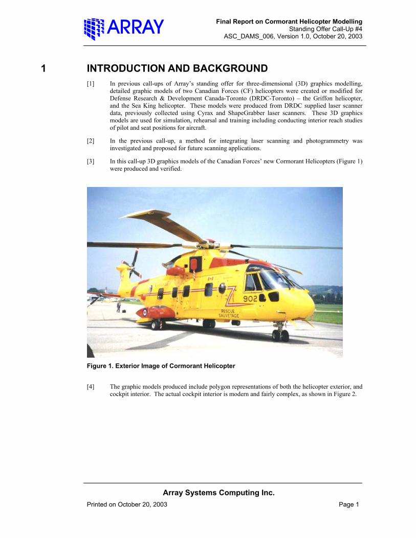
[3] In this call-up 3D graphics models of the Canadian Forces’ new Cormorant Helicopters (Figure 1) were produced and verified.
Figure 1. Exterior Image of Cormorant Helicopter
[4] The graphic models produced include polygon representations of both the helicopter exterior, and cockpit interior. The actual cockpit interior is modern and fairly complex, as shown in Figure 2.
Final Report on Cormorant Helicopter Modelling Standing Offer Call-Up #4
ASC_DAMS_006, Version 1.0, October 20, 2003
Array Systems Computing Inc.
Printed on October 20, 2003 Page 2
Figure 2. Interior of Cormorant Helicopter
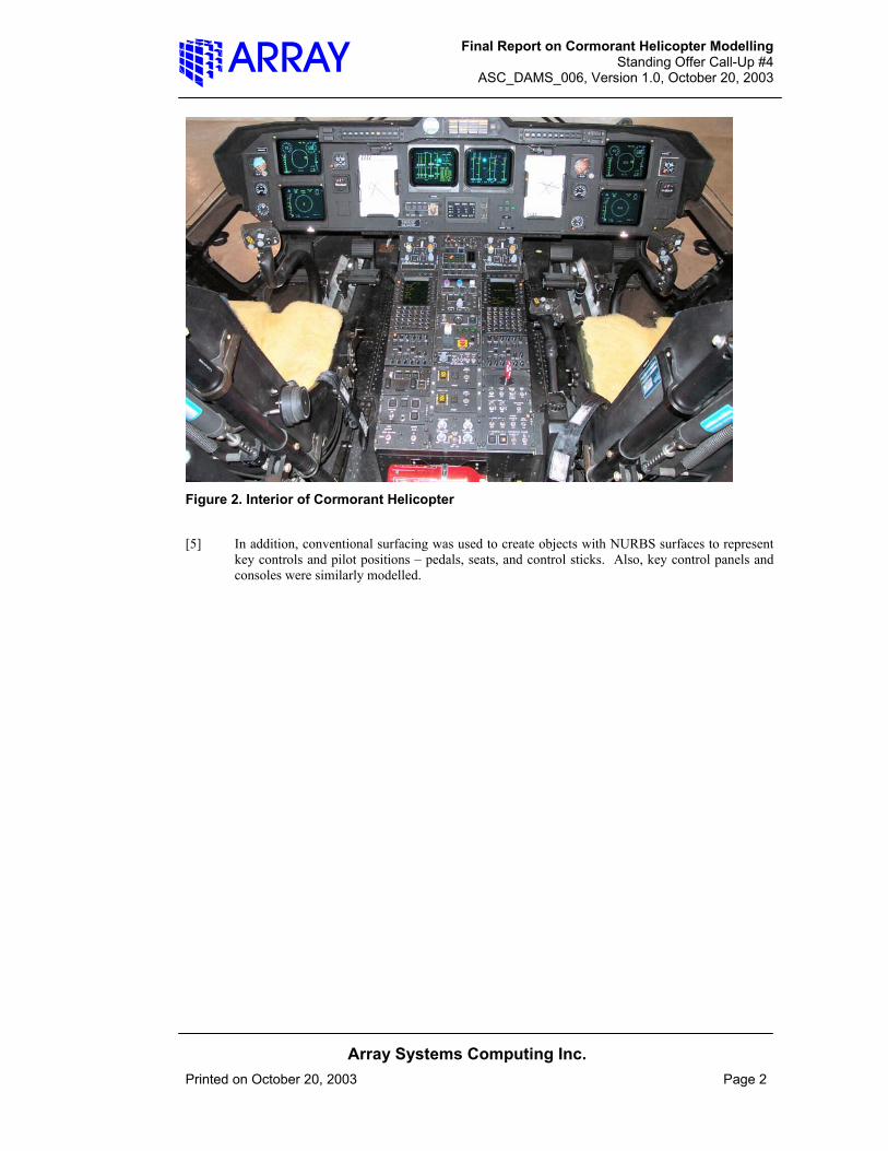
[5] In addition, conventional surfacing was used to create objects with NURBS surfaces to represent key controls and pilot positions – pedals, seats, and control sticks. Also, key control panels and consoles were similarly modelled.

Final Report on Cormorant Helicopter Modelling Standing Offer Call-Up #4
ASC_DAMS_006, Version 1.0, October 20, 2003
Array Systems Computing Inc.
Printed on October 20, 2003 Page 3
2 DETAILS AND RESULTS OF INDIVIDUAL TASKS
2.1 Interior Graphics Modelling of Cormorant Helicopter [1] The interior model of the Cormorant cockpit was produced in two forms: a detailed polygon
based representation from the laser scan data supplied by DRDC-Toronto, and a NURBS surface model for key objects derived from the polygon model.
[2] The NURBS surface model is space efficient, scalable, and convenient to work with. It is mainly used for representing critical control objects (sticks, pedals), seat positions and range of motions.
2.1.1 Alignment and Polygonization of Data [1] DRDC-Toronto’s contractor Innovision Inc. scanned the interior of the Cormorant cockpit in late
2001 using a ShapeGrabber Laser Scanner. The cockpit data consisted of 71 images, with standard deviations of 200-600 microns. These raw scans were aligned and processed using Innovemetric’s Polyworks/Modeler software.
[2] Polywork’s IMAlign was used to align scans with respect to each other. The average mean standard error for the scan alignments was 500 microns, with a point scan density interpolated to a 1 mm grid. Figure 3 shows the aligned point clouds in IMAlign.
Figure 3. Point Cloud Scans of Aircraft Cockpit Interior

Final Report on Cormorant Helicopter Modelling Standing Offer Call-Up #4
ASC_DAMS_006, Version 1.0, October 20, 2003
Array Systems Computing Inc.
Printed on October 20, 2003 Page 4
[3] Following notice from DRDC-Toronto, it was confirmed that the raw data from the ShapeGrabber scanner was mirrored from left to right for the cockpit interior, which was the result of operating the ShapeGrabber in an inverted position. The effect was confirmed by comparing the aligned scan data to digital images of non-symmetric control panel regions, as shown in Figure 4.
Note shift in this object in image below
Figure 4. Confirmation of Mirroring of Data from ShapeGrabber Scanner
[4] This mirror effect was corrected in the transformed polygon model, by mirroring the entire cockpit ShapeGrabber data along an axis parallel to the longitudinal axis of the helicopter.
[5] After the alignment was completed and verified, scan overlap was reduced using IMAlign. Next the scanner point clouds were merged and polygonized using IMMerge. The following
Final Report on Cormorant Helicopter Modelling Standing Offer Call-Up #4
ASC_DAMS_006, Version 1.0, October 20, 2003
Array Systems Computing Inc.
Printed on October 20, 2003 Page 5
parameters were used for the merging, based on the standard deviation of the point cloud alignment averaging 0.5 mm:
a. Maximum Distance: 5mm b. Sample Grid 1 mm c. Smoothing Radius 3 mm d. Smoothing Tolerance 1.5 mm e. Overall tolerance reduction 0.050 mm.
[6] This merging resulted in an initial polygon model of 3.4 million Polygons. To work with this data efficiently, it was further reduced to 0.5 mm tolerance using IMCompress. The reduced interior polygon model contains approximately 773000 Polygons.
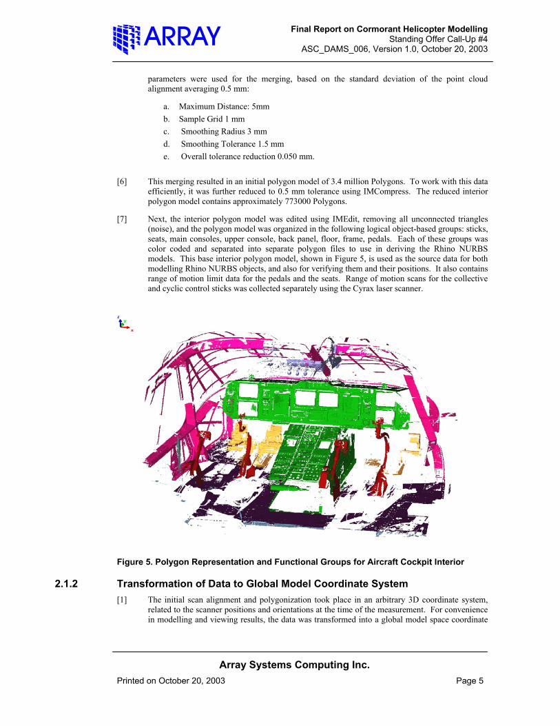
[7] Next, the interior polygon model was edited using IMEdit, removing all unconnected triangles (noise), and the polygon model was organized in the following logical object-based groups: sticks, seats, main consoles, upper console, back panel, floor, frame, pedals. Each of these groups was color coded and separated into separate polygon files to use in deriving the Rhino NURBS models. This base interior polygon model, shown in Figure 5, is used as the source data for both modelling Rhino NURBS objects, and also for verifying them and their positions. It also contains range of motion limit data for the pedals and the seats. Range of motion scans for the collective and cyclic control sticks was collected separately using the Cyrax laser scanner.
Figure 5. Polygon Representation and Functional Groups for Aircraft Cockpit Interior
2.1.2 Transformation of Data to Global Model Coordinate System [1] The initial scan alignment and polygonization took place in an arbitrary 3D coordinate system,
related to the scanner positions and orientations at the time of the measurement. For convenience in modelling and viewing results, the data was transformed into a global model space coordinate

Final Report on Cormorant Helicopter Modelling Standing Offer Call-Up #4
ASC_DAMS_006, Version 1.0, October 20, 2003
Array Systems Computing Inc.
Printed on October 20, 2003 Page 6
system, related to the logical construction of the helicopter. This datum definition and transformation was defined using IMInspect, part of the Polyworks\Inspector software.
[2] The datum was defined as follows: planes were fit to both the floor of the cockpit, and the back wall of the cockpit. These planes were intersected to a line that then lies approximately perpendicular to the longitudinal (symmetry) axis of the aircraft, on the floor surface. Another plane is then constructed by rotating the floor plane 90 degrees around this intersection line. This creates a plane perpendicular to the floor across the cockpit, also approximately perpendicular to the aircraft longitudinal axis. The origin is chosen on the line of rotation outside the cockpit area. The origin point, intersection line, and rotated plane enable a point, line, plane (123) transform to this new datum. This relates all primary coordinate planes to the aircraft cockpit floor (the zero Z datum), the longitudinal axis (Y axis), and a mutually perpendicular X axis, transverse across the back of the cockpit. Figure 6 shows this datum definition and construction.
Figure 6. Definition of Global Model Coordinate System
[3] Finally, the entire interior polygon model was mirrored about the YZ axis to correct the previously noted ShapeGrabber mirror of the scan data. This global model coordinate system, or datum, is used for the rest of the project, including aligning the exterior shell to this system, described later in this report.

Final Report on Cormorant Helicopter Modelling Standing Offer Call-Up #4
ASC_DAMS_006, Version 1.0, October 20, 2003
Array Systems Computing Inc.
Printed on October 20, 2003 Page 7
2.1.3 Alignment of Seats and Seat Rails In Cockpit [1] One significant challenge encountered during the Cormorant modelling consisted of accurately
relocating the seats and seat rails on the floor of the cockpit. To scan the Interior of the cockpit, due to space restrictions, the seats and rail assembly were removed from the cockpit and scanned separately in an alternate location.
[2] Prior to repositioning the seat in the cockpit, one seat and rail assembly was aligned, merged and edited separately from the interior model. Also, a second seat in the extreme positions was aligned using the fixed base rail to resolve the range of motion seat travel and limits. It was noted that the seats have both translational and rotational degrees of freedom. Modelling notes indicated that three tilt (or rotation) positions are possible in the Cormorant seats. However, one seat tilt was found inappropriate for pilot use and banned by the CF. Scan data defining the limits for all range of motion translations was found, but data for only one rotation position of one seat at a single translation position could be located. Based on the scan data and the known pivot point location, it was determined that this seat tilt was scanned in the upper-forward position. An important assumption (as corroborated by DRDC Toronto) was made that both translations and rotations of the pilot and co-pilot seats are identical.
[3] For the model production, the seats and rails were required to be accurately repositioned on the cockpit floor. The lower seat rail is held in position using bolts on flanges attached to the rails. The location of the seat rail bolt holes on the floor should accurately enable the repositioning of the seat rails. However, the laser scanning of holes was subject to significant edge effects and noise. Data alignment, processing, and polygonization of the laser scan data further affects the hole shape and definition, though its location should remain constant. Also, the dark color and lack of vertical relief in the floor caused difficulty in Polyworks shape defined alignment of objects. Since there is no vertical relief on the floor to position the seats (e.g. locating pins or blocks), repositioning the seat was tedious and difficult, and could not be achieved automatically. Using automatic techniques, considerable slippage would occur resulting in unacceptable errors. However, using a manual process under high magnification, the locations were determined and seats were realigned. An additional constraint of the rails and flanges on the floor surface was introduced to assist the repositioning process. Figure 7 shows a sample seat rail flange and locating floor bolt hole/pad.

Final Report on Cormorant Helicopter Modelling Standing Offer Call-Up #4
ASC_DAMS_006, Version 1.0, October 20, 2003
Array Systems Computing Inc.
Printed on October 20, 2003 Page 8
Flange and bolt-holes for centering seat rails (1 of 4)
Figure 7. Detail of Seat and Seat Rail Positioning on Cockpit Floor [4] A further drawback of this repositioning method is that it was not possible to verify the location of
seat repositioning with redundant scan data. However, as two operators, both the author and DRDC specialist Rob Mertens independently performed this manual seat rail location; results were cross-checked for operator bias in positioning. This check confirmed consistent locating of the seats to within 1 mm (mean error), 2.5 mm (standard error) of each other between operators.
[5] For future seat and rail scanning, we recommend using an alternate relocating technique, such as mounting locating pins or blocks in the mating rail and floor locations that can be automatically aligned to each other using shape based techniques built into Polyworks.
2.1.4 Interior Surfacing and Range of Motion of Key Objects Using Rhino [1] Key objects and control surfaces inside the cockpit were modelled using conventional NURBS
surfaces with the Rhino software package. These objects were modelled from the interior polygon data, and the main movable control objects were also modelled in extra positions at their extreme limits of range of motion.
[2] These Rhino NURBS objects may be conveniently used in reach and accommodation studies. Rhino can export these objects to a variety of NURBS or polygon formats to use with other software packages like Safework.
Final Report on Cormorant Helicopter Modelling Standing Offer Call-Up #4
ASC_DAMS_006, Version 1.0, October 20, 2003
Array Systems Computing Inc.
Printed on October 20, 2003 Page 9
2.1.4.1 Consoles and Control Panels [1] The main surfaces of the following control panels were surfaced in Rhino: the front control panel,
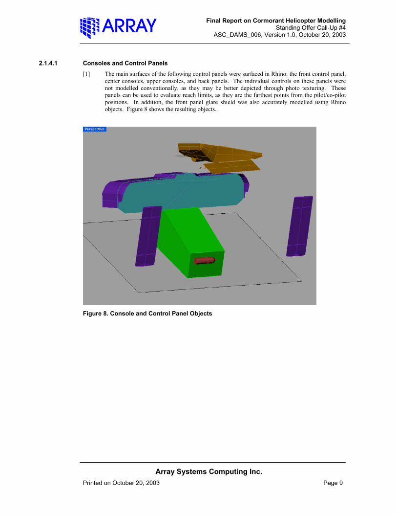
center consoles, upper consoles, and back panels. The individual controls on these panels were not modelled conventionally, as they may be better depicted through photo texturing. These panels can be used to evaluate reach limits, as they are the farthest points from the pilot/co-pilot positions. In addition, the front panel glare shield was also accurately modelled using Rhino objects. Figure 8 shows the resulting objects.
Figure 8. Console and Control Panel Objects
Final Report on Cormorant Helicopter Modelling Standing Offer Call-Up #4
ASC_DAMS_006, Version 1.0, October 20, 2003
Array Systems Computing Inc.
Printed on October 20, 2003 Page 10
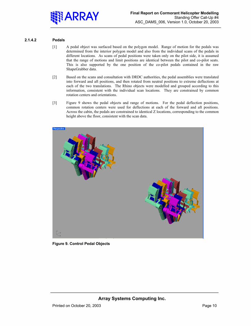
2.1.4.2 Pedals [1] A pedal object was surfaced based on the polygon model. Range of motion for the pedals was
determined from the interior polygon model and also from the individual scans of the pedals in different locations. As scans of pedal positions were taken only on the pilot side, it is assumed that the range of motions and limit positions are identical between the pilot and co-pilot seats. This is also supported by the one position of the co-pilot pedals contained in the raw ShapeGrabber data.
[2] Based on the scans and consultation with DRDC authorities, the pedal assemblies were translated into forward and aft positions, and then rotated from neutral positions to extreme deflections at each of the two translations. The Rhino objects were modelled and grouped according to this information, consistent with the individual scan locations. They are constrained by common rotation centers and orientations.
[3] Figure 9 shows the pedal objects and range of motions. For the pedal deflection positions, common rotation centers were used for deflections at each of the forward and aft positions. Across the cabin, the pedals are constrained to identical Z locations, corresponding to the common height above the floor, consistent with the scan data.
Figure 9. Control Pedal Objects
Final Report on Cormorant Helicopter Modelling Standing Offer Call-Up #4
ASC_DAMS_006, Version 1.0, October 20, 2003
Array Systems Computing Inc.
Printed on October 20, 2003 Page 11
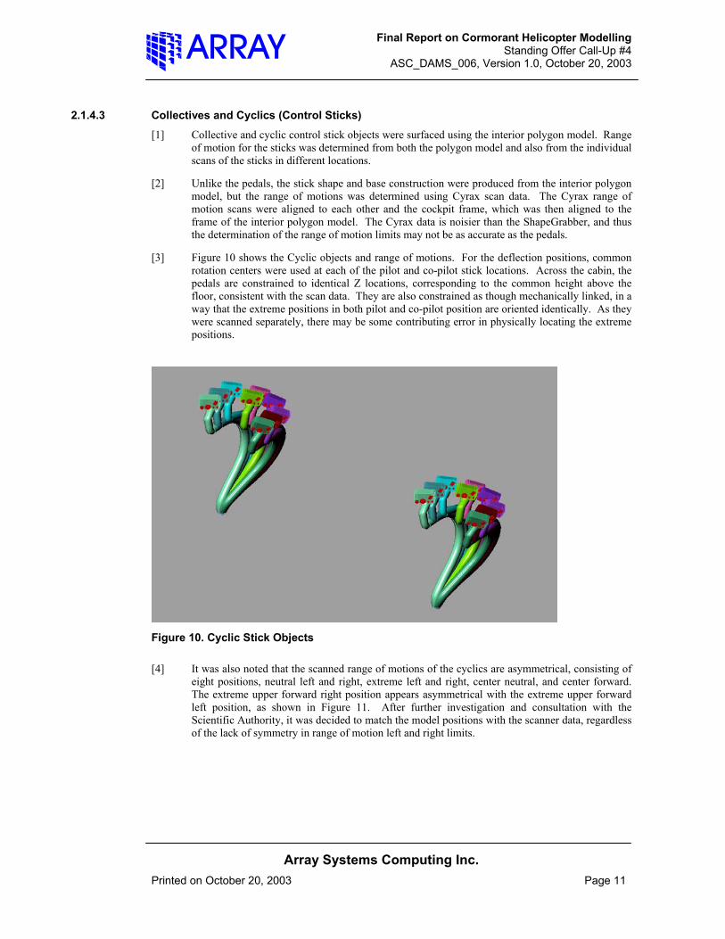
2.1.4.3 Collectives and Cyclics (Control Sticks) [1] Collective and cyclic control stick objects were surfaced using the interior polygon model. Range
of motion for the sticks was determined from both the polygon model and also from the individual scans of the sticks in different locations.
[2] Unlike the pedals, the stick shape and base construction were produced from the interior polygon model, but the range of motions was determined using Cyrax scan data. The Cyrax range of motion scans were aligned to each other and the cockpit frame, which was then aligned to the frame of the interior polygon model. The Cyrax data is noisier than the ShapeGrabber, and thus the determination of the range of motion limits may not be as accurate as the pedals.
[3] Figure 10 shows the Cyclic objects and range of motions. For the deflection positions, common rotation centers were used at each of the pilot and co-pilot stick locations. Across the cabin, the pedals are constrained to identical Z locations, corresponding to the common height above the floor, consistent with the scan data. They are also constrained as though mechanically linked, in a way that the extreme positions in both pilot and co-pilot position are oriented identically. As they were scanned separately, there may be some contributing error in physically locating the extreme positions.
Figure 10. Cyclic Stick Objects [4] It was also noted that the scanned range of motions of the cyclics are asymmetrical, consisting of
eight positions, neutral left and right, extreme left and right, center neutral, and center forward. The extreme upper forward right position appears asymmetrical with the extreme upper forward left position, as shown in Figure 11. After further investigation and consultation with the Scientific Authority, it was decided to match the model positions with the scanner data, regardless of the lack of symmetry in range of motion left and right limits.

Final Report on Cormorant Helicopter Modelling Standing Offer Call-Up #4
ASC_DAMS_006, Version 1.0, October 20, 2003
Array Systems Computing Inc.
Printed on October 20, 2003 Page 12
Note left and right forward positions not symmetrical.
Figure 11. Asymmetrical Cyclic Range of Motion Noted
[5] The collective range of motion modelling is similar to that used with the cyclic, but there are only two positions, extreme forward and back, being rotations about a common center. As scan data for both extreme positions was only clear on the pilot’s side, the co-pilot collective is assumed to have the same range of motion as the pilot. This is logical, as the two are mechanically connected, as with the cyclic. It is also consistent with the scan data, showing the co-pilot collective in a single position.
Final Report on Cormorant Helicopter Modelling Standing Offer Call-Up #4
ASC_DAMS_006, Version 1.0, October 20, 2003
Array Systems Computing Inc.
Printed on October 20, 2003 Page 13
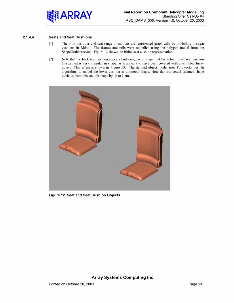
2.1.4.4 Seats and Seat Cushions [1] The pilot positions and seat range of motions are represented graphically by modelling the seat
cushions in Rhino. The frames and rails were modelled using the polygon model from the ShapeGrabber scans. Figure 12 shows the Rhino seat cushion representation.
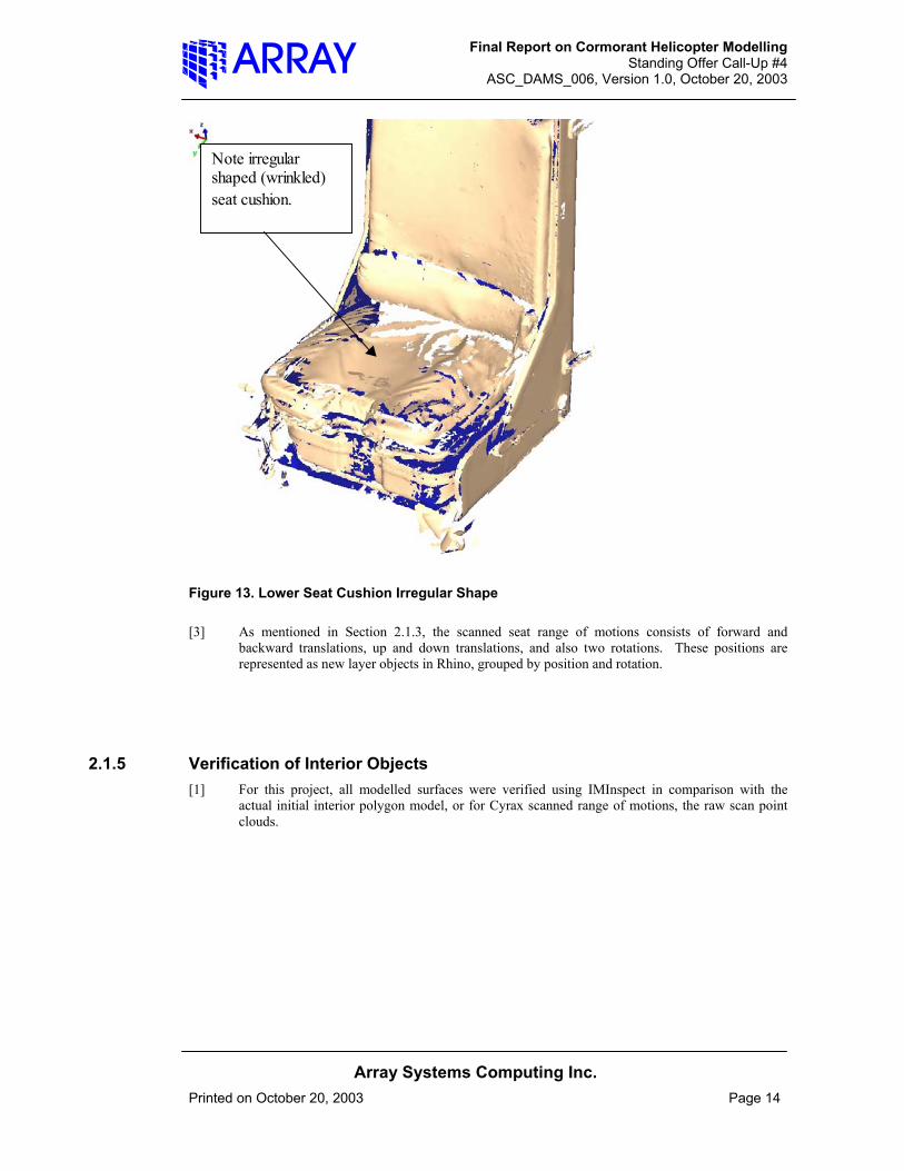
[2] Note that the back seat cushion appears fairly regular in shape, but the actual lower seat cushion as scanned is very irregular in shape, as it appears to have been covered with a wrinkled fuzzy cover. This effect is shown in Figure 13. The derived object model uses Polyworks best-fit algorithms to model the lower cushion as a smooth shape. Note that the actual scanned shape deviates from this smooth shape by up to 2 cm.
Figure 12. Seat and Seat Cushion Objects
Final Report on Cormorant Helicopter Modelling Standing Offer Call-Up #4
ASC_DAMS_006, Version 1.0, October 20, 2003
Array Systems Computing Inc.
Printed on October 20, 2003 Page 14
Note irregular shaped (wrinkled) seat cushion.
Figure 13. Lower Seat Cushion Irregular Shape [3] As mentioned in Section 2.1.3, the scanned seat range of motions consists of forward and
backward translations, up and down translations, and also two rotations. These positions are represented as new layer objects in Rhino, grouped by position and rotation.
2.1.5 Verification of Interior Objects [1] For this project, all modelled surfaces were verified using IMInspect in comparison with the
actual initial interior polygon model, or for Cyrax scanned range of motions, the raw scan point clouds.
Final Report on Cormorant Helicopter Modelling Standing Offer Call-Up #4
ASC_DAMS_006, Version 1.0, October 20, 2003
Array Systems Computing Inc.
Printed on October 20, 2003 Page 15
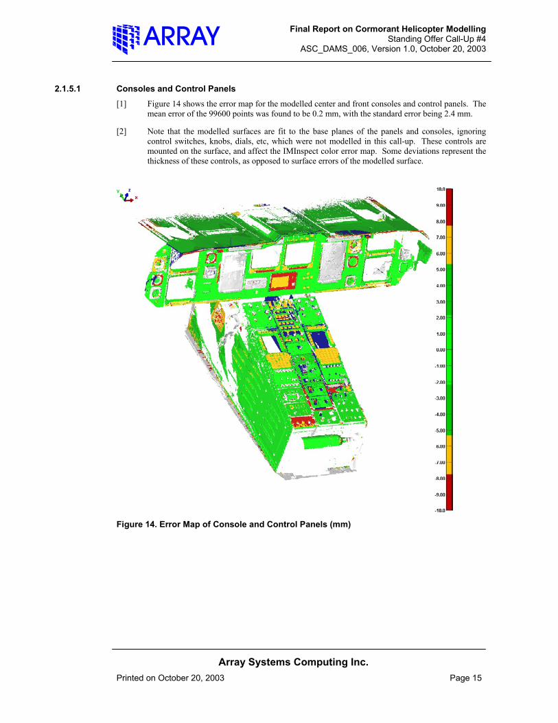
2.1.5.1 Consoles and Control Panels [1] Figure 14 shows the error map for the modelled center and front consoles and control panels. The
mean error of the 99600 points was found to be 0.2 mm, with the standard error being 2.4 mm.
[2] Note that the modelled surfaces are fit to the base planes of the panels and consoles, ignoring control switches, knobs, dials, etc, which were not modelled in this call-up. These controls are mounted on the surface, and affect the IMInspect color error map. Some deviations represent the thickness of these controls, as opposed to surface errors of the modelled surface.
Figure 14. Error Map of Console and Control Panels (mm)
Final Report on Cormorant Helicopter Modelling Standing Offer Call-Up #4
ASC_DAMS_006, Version 1.0, October 20, 2003
Array Systems Computing Inc.
Printed on October 20, 2003 Page 16
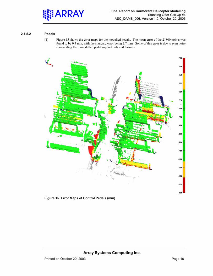
2.1.5.2 Pedals [1] Figure 15 shows the error maps for the modelled pedals. The mean error of the 21800 points was
found to be 0.3 mm, with the standard error being 2.7 mm. Some of this error is due to scan noise surrounding the unmodelled pedal support rails and fixtures.
Figure 15. Error Maps of Control Pedals (mm)
Final Report on Cormorant Helicopter Modelling Standing Offer Call-Up #4
ASC_DAMS_006, Version 1.0, October 20, 2003
Array Systems Computing Inc.
Printed on October 20, 2003 Page 17
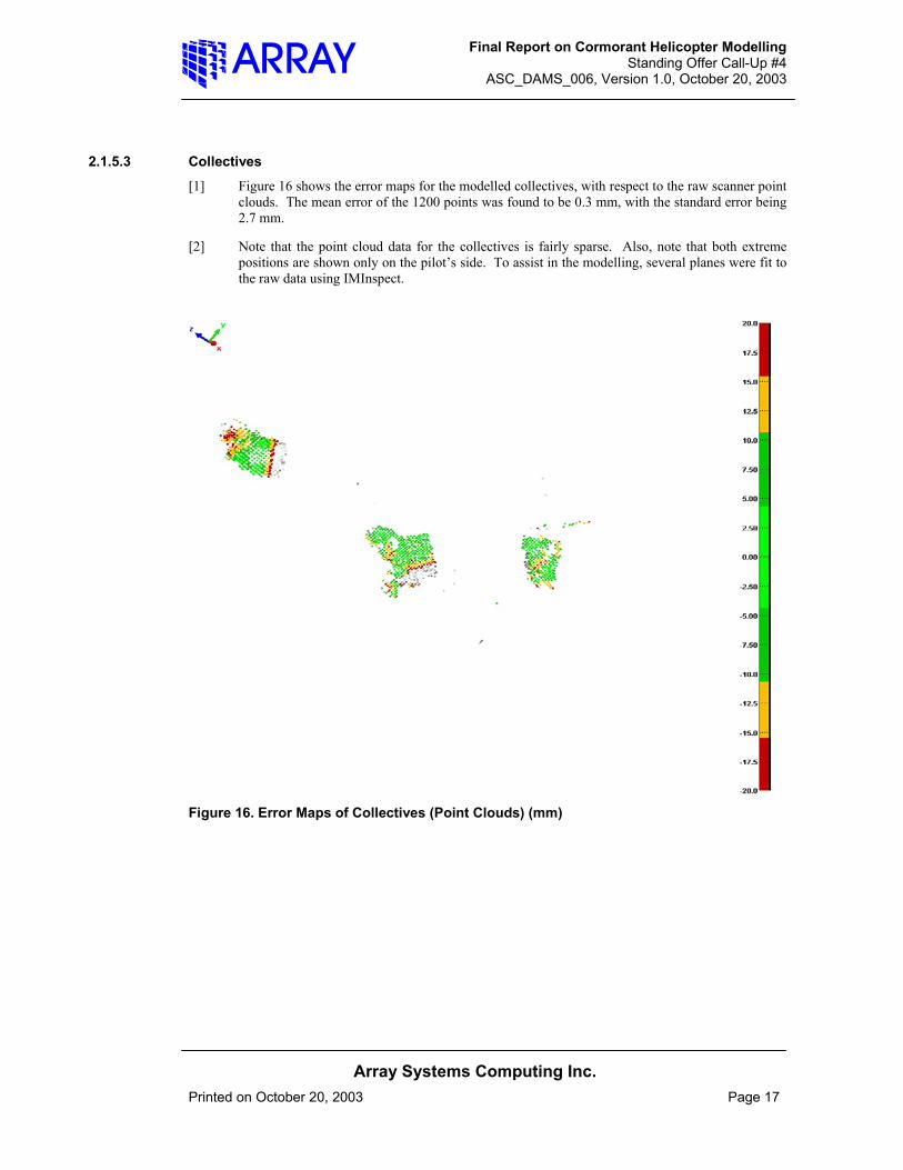
2.1.5.3 Collectives [1] Figure 16 shows the error maps for the modelled collectives, with respect to the raw scanner point
clouds. The mean error of the 1200 points was found to be 0.3 mm, with the standard error being 2.7 mm.
[2] Note that the point cloud data for the collectives is fairly sparse. Also, note that both extreme positions are shown only on the pilot’s side. To assist in the modelling, several planes were fit to the raw data using IMInspect.
Figure 16. Error Maps of Collectives (Point Clouds) (mm)
Final Report on Cormorant Helicopter Modelling Standing Offer Call-Up #4
ASC_DAMS_006, Version 1.0, October 20, 2003
Array Systems Computing Inc.
Printed on October 20, 2003 Page 18
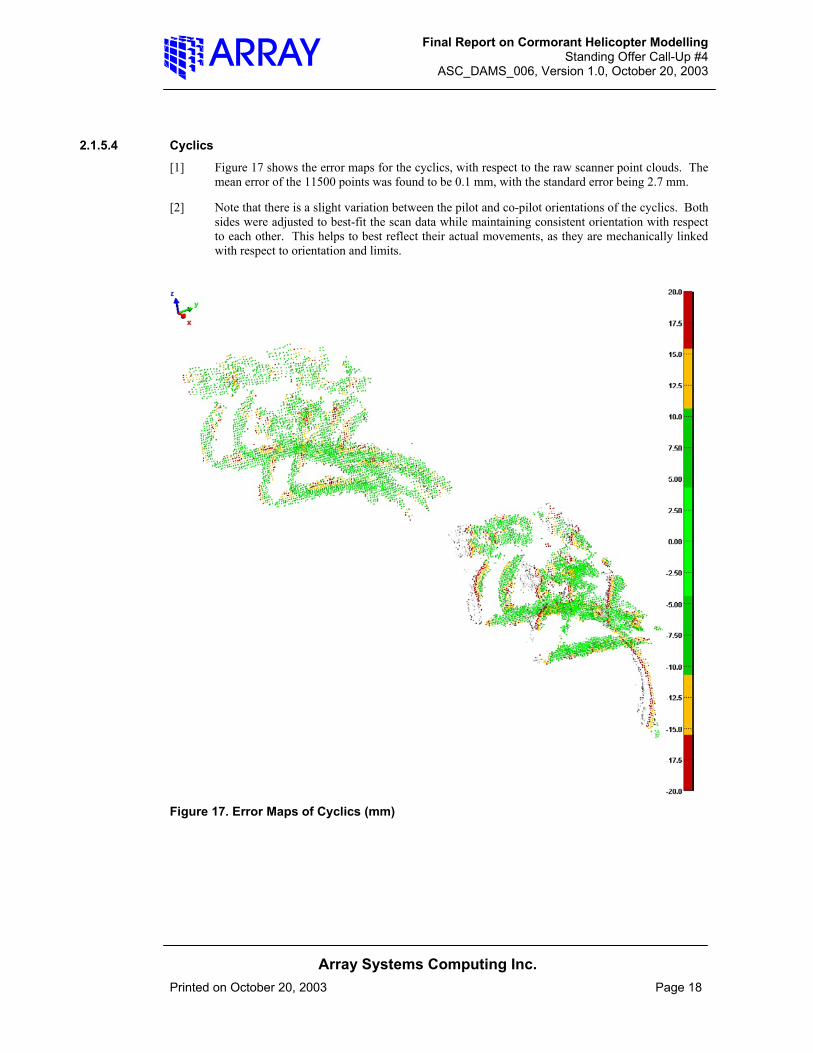
2.1.5.4 Cyclics [1] Figure 17 shows the error maps for the cyclics, with respect to the raw scanner point clouds. The
mean error of the 11500 points was found to be 0.1 mm, with the standard error being 2.7 mm.
[2] Note that there is a slight variation between the pilot and co-pilot orientations of the cyclics. Both sides were adjusted to best-fit the scan data while maintaining consistent orientation with respect to each other. This helps to best reflect their actual movements, as they are mechanically linked with respect to orientation and limits.
Figure 17. Error Maps of Cyclics (mm)
Final Report on Cormorant Helicopter Modelling Standing Offer Call-Up #4
ASC_DAMS_006, Version 1.0, October 20, 2003
Array Systems Computing Inc.
Printed on October 20, 2003 Page 19
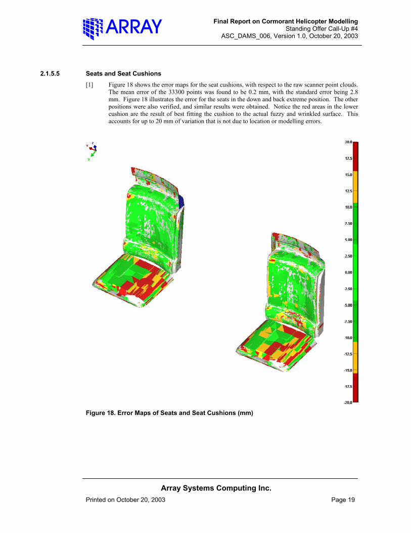
2.1.5.5 Seats and Seat Cushions [1] Figure 18 shows the error maps for the seat cushions, with respect to the raw scanner point clouds.
The mean error of the 33300 points was found to be 0.2 mm, with the standard error being 2.8 mm. Figure 18 illustrates the error for the seats in the down and back extreme position. The other positions were also verified, and similar results were obtained. Notice the red areas in the lower cushion are the result of best fitting the cushion to the actual fuzzy and wrinkled surface. This accounts for up to 20 mm of variation that is not due to location or modelling errors.
Figure 18. Error Maps of Seats and Seat Cushions (mm)
Final Report on Cormorant Helicopter Modelling Standing Offer Call-Up #4
ASC_DAMS_006, Version 1.0, October 20, 2003
Array Systems Computing Inc.
Printed on October 20, 2003 Page 20
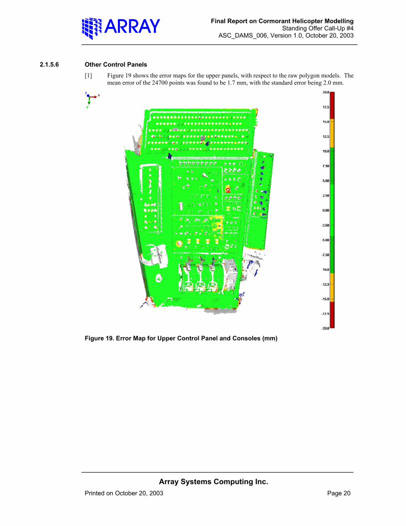
2.1.5.6 Other Control Panels [1] Figure 19 shows the error maps for the upper panels, with respect to the raw polygon models. The
mean error of the 24700 points was found to be 1.7 mm, with the standard error being 2.0 mm.
Figure 19. Error Map for Upper Control Panel and Consoles (mm)

Final Report on Cormorant Helicopter Modelling Standing Offer Call-Up #4
ASC_DAMS_006, Version 1.0, October 20, 2003
Array Systems Computing Inc.
Printed on October 20, 2003 Page 21
[2] Figure 20 shows the error maps for the back panels, with respect to the raw polygon models. The
mean error of the 9300 points was found to be 0.8 mm, with the standard error being 2.4 mm.
Figure 20. Error Map for Back Control Panels (mm)
Final Report on Cormorant Helicopter Modelling Standing Offer Call-Up #4
ASC_DAMS_006, Version 1.0, October 20, 2003
Array Systems Computing Inc.
Printed on October 20, 2003 Page 22
2.2 Exterior Graphics Modelling of Cormorant Helicopter [1] In this call-up, considerable time and effort was spent processing and modelling the exterior shell,
windows, and other exterior fixtures.
2.2.1 Alignment and Polygonization of Data [1] The exterior of the Cormorant was previously scanned using DRDC-Toronto’s Cyrax laser
scanner, with measurement accuracy of 3-6 mm. The Scientific Authority for this call-up provided this data.
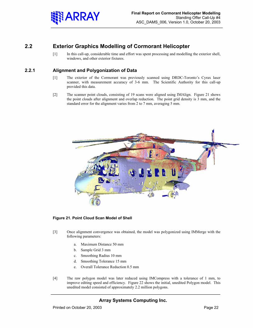
[2] The scanner point clouds, consisting of 19 scans were aligned using IMAlign. Figure 21 shows the point clouds after alignment and overlap reduction. The point grid density is 3 mm, and the standard error for the alignment varies from 2 to 7 mm, averaging 5 mm.
Figure 21. Point Cloud Scan Model of Shell
[3] Once alignment convergence was obtained, the model was polygonized using IMMerge with the following parameters:
a. Maximum Distance 50 mm b. Sample Grid 3 mm c. Smoothing Radius 10 mm d. Smoothing Tolerance 15 mm e. Overall Tolerance Reduction 0.5 mm
[4] The raw polygon model was later reduced using IMCompress with a tolerance of 1 mm, to improve editing speed and efficiency. Figure 22 shows the initial, unedited Polygon model. This unedited model consisted of approximately 2.2 million polygons.

Final Report on Cormorant Helicopter Modelling Standing Offer Call-Up #4
ASC_DAMS_006, Version 1.0, October 20, 2003
Array Systems Computing Inc.
Printed on October 20, 2003 Page 23
[5] The original scans were taken using metres as the measurement unit. For compatibility with ShapeGrabber data, the model was scaled to convert the units to millimeters. Also, polygons were logically divided into appropriate groups such as hull, rotors, landing gear, fixtures, etc.
Figure 22. Unedited Polygon Model of Exterior Shell
2.2.2 Advanced Polygon Editing and Reconstruction [1] The raw polygon model of the Cormorant Exterior required considerable polygon editing and
reconstruction for the following reasons:
• Some scanned areas were obscured by features on the exterior, causing shadows. These are areas with no scan data, or partial data. This is an unavoidable consequence of scanning the upper areas of the helicopter from an elevated lift. This effect is most noticeable at the back of the helicopter, where large areas were obscured by the tail rotor.
• Areas such as windows did not reflect the Cyrax laser; instead, it penetrated into the interior. This has two effects: no surface data on the windows, and significant noise inside the model.
• There are noticeable multipath errors and noise around the edges of features such as windows, intake openings, and other fixtures.
• Due to access, line-of-sight, and minimum stand-off considerations, the bottom of the helicopter was not scanned.
• The surface scan data itself is subject to measurement errors of 3-6 mm. This causes considerable noise and bumpiness that must be smoothed in the processing.
• Helicopter surface color variations, especially black areas like logos, flags, text, etc., cause poor laser return signals resulting in missing data and/or noisy data around these areas.
[2] Other, smaller sources of potential error are site-specific refraction, vibration of sensor and or object, dust, lighting effects, temperature variations, etc.

Final Report on Cormorant Helicopter Modelling Standing Offer Call-Up #4
ASC_DAMS_006, Version 1.0, October 20, 2003
Array Systems Computing Inc.
Printed on October 20, 2003 Page 24
[3] Polyworks’s IMEdit program provides extensive tools for surface editing, reconstruction, smoothing and filtering. However, to achieve effective results, considerable time was required, approximately 4/9 of the total time budget for this project. Some of the advanced techniques used are briefly described below.
2.2.2.1 Edge Reconstruction [1] Polyworks\Modeler V8 contains a number of existing and new tools for edge reconstruction.
These tools enabled the typical edge effects and noise caused by effects such as multipath to be removed in a semi-automated process.
[2] Figure 23 shows a sample area before and after successful edge reconstruction. Approximately 22 edges were reconstructed using this technique.
Edge to be reconstructed
Reconstructed Edge
Figure 23. Example of Polyworks Edge Reconstruction Using IMEdit’s Tools

Final Report on Cormorant Helicopter Modelling Standing Offer Call-Up #4
ASC_DAMS_006, Version 1.0, October 20, 2003
Array Systems Computing Inc.
Printed on October 20, 2003 Page 25
2.2.2.2 NURBS Modelling In Polyworks [1] Polyworks V8 has very recently added tools for fitting curve networks and NURBS surfaces as a
modelling aid. These surfaces are typically used in rapid-surfacing objects. Practical uses include reconstructing areas, smoothing underlying polygon meshes, rapid surfacing objects, etc.
[2] For this project, this new feature was useful in constructing windows. Window areas were cleaned of noise and degenerate polygons, surrounded by optimized curves, and fit with curve networks and NURBS surfaces. This enabled accurate and rapid reconstruction of window surfaces. Once the NURBS were defined and fit, they were inserted into the mesh and triangulated. The edges of the windows were then defined using curves fit to the original polygon model. The windows themselves are stored in a separate group, which contains translucent material, tinted appropriately.
[3] Figure 24 shows an example of the curve network used to reconstruct a missing window.
C ur v e /P a t c h N e t wo r k f o r N U R B S sur f a c e s
Figure 24. Example of Polyworks NURBS Curve Network and Patch Mesh
2.2.2.3 Filtering and Smoothing of Data, Hole Filling [1] The majority of time spent in the exterior polygon editing was spent smoothing, filtering surfaces,
and filling holes. Although IMEdit’s v8 has an improved hole-filling routine, it was found to not provide the desired results, and had some unsatisfactory side-effects, namely creating new holes. This side effect has been reported to Innovemetric for future action. As a result, most holes were filled manually using triangulation and manual selection of polygons/vertexes.

Final Report on Cormorant Helicopter Modelling Standing Offer Call-Up #4
ASC_DAMS_006, Version 1.0, October 20, 2003
Array Systems Computing Inc.
Printed on October 20, 2003 Page 26
[2] Over 200 Bezier surfaces were fit to the model for use in smoothing and reconstruction. Also, global filtering, smoothing, and mesh optimizing were used to improve the model. The most challenging areas to edit/reconstruct were located along sharp edges with high curvature. These areas contained considerable noise and/or degenerate triangles. Also, the edge areas were most subject to data voids from shadow effects.
2.2.2.4 Modelling of External Fixtures and Objects [1] In addition to the hull and window editing and smoothing, there were a number of external
fixtures on the helicopter surface including – rotors, landing gear and wheels, exterior railings, windshield wipers, struts, antenna, a winch, and a spot-light. Each of these fixtures contained partial scan data, some of it fairly noisy. Rhino conventional NURBS surfacing was used to reconstruct these fixtures. The Rhino surfaces were then polygonized and re-imported into the exterior polygon model. Figure 25 shows these fixtures in the final exterior model.
Figure 25. Models of External Fixtures of Aircraft
2.2.3 Transformation to Global Model Coordinate System [1] After the exterior modelling and reconstruction was completed locally, the entire exterior shell
and fixtures were aligned with respect to the previously edited interior model, into the Global Model coordinate system.

Final Report on Cormorant Helicopter Modelling Standing Offer Call-Up #4
ASC_DAMS_006, Version 1.0, October 20, 2003
Array Systems Computing Inc.
Printed on October 20, 2003 Page 27
[2] The primary common feature to enable this alignment is the adhesive tape that was applied to the exterior of the cockpit windows prior to scanning. This window tape was well captured using the ShapeGrabber from the inside, and could be fit to the reconstructed cockpit windows.
[3] In addition, parts of the cockpit window frames could be used for the initial rough alignment. The alignment of exterior to interior is verified by comparing the fitting errors to this window tape, with the resulting color error map shown in Figure 26. The mean error of this fit is 0.3 mm, and standard error is 11.7 mm. Most of this standard error is due to the significant scanner noise occurring around the window frame, and also is affected by minor surface variations that were not modelled in order to reduce the total polygon count.
Figure 26. Error Map of Exterior to Interior Alignment

Final Report on Cormorant Helicopter Modelling Standing Offer Call-Up #4
ASC_DAMS_006, Version 1.0, October 20, 2003
Array Systems Computing Inc.
Printed on October 20, 2003 Page 28
2.2.4 Verification of External Model and Fixtures [1] After editing and transformation of the shell were completed, the modelled surfaces and objects
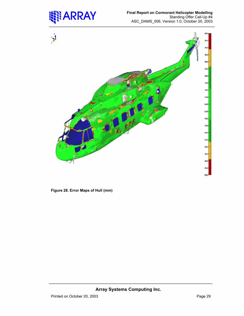
were compared to the original polygon model using IMInspect. Note that the final model is compared to the original data including its noise and edge effects. In the color maps below, certain areas may appear to contain large variations from the modelled surface, these are also side-effects of extraneous noise, and do not represent model errors. Other areas that appear as grey are the result of comparison to areas that have no data, due to effects such as shadowing.
[2] Figure 27 shows the color error map of the hull with respect to its original data. The mean error of this comparison is 0.1 mm and the standard error is 4.2 mm.
Figure 27. Error Maps of Hull (mm) (cont’d on next page)
Final Report on Cormorant Helicopter Modelling Standing Offer Call-Up #4
ASC_DAMS_006, Version 1.0, October 20, 2003
Array Systems Computing Inc.
Printed on October 20, 2003 Page 29
Figure 28. Error Maps of Hull (mm)
Final Report on Cormorant Helicopter Modelling Standing Offer Call-Up #4
ASC_DAMS_006, Version 1.0, October 20, 2003
Array Systems Computing Inc.
Printed on October 20, 2003 Page 30
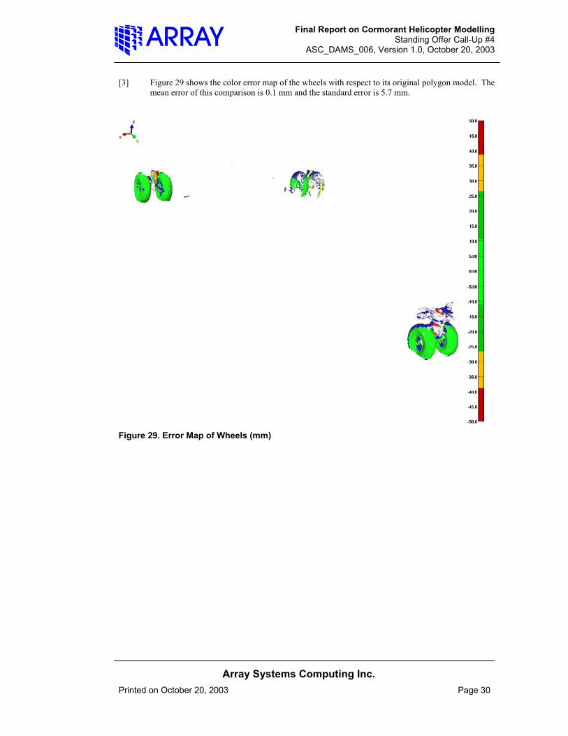
[3] Figure 29 shows the color error map of the wheels with respect to its original polygon model. The mean error of this comparison is 0.1 mm and the standard error is 5.7 mm.
Figure 29. Error Map of Wheels (mm)
Final Report on Cormorant Helicopter Modelling Standing Offer Call-Up #4
ASC_DAMS_006, Version 1.0, October 20, 2003
Array Systems Computing Inc.
Printed on October 20, 2003 Page 31
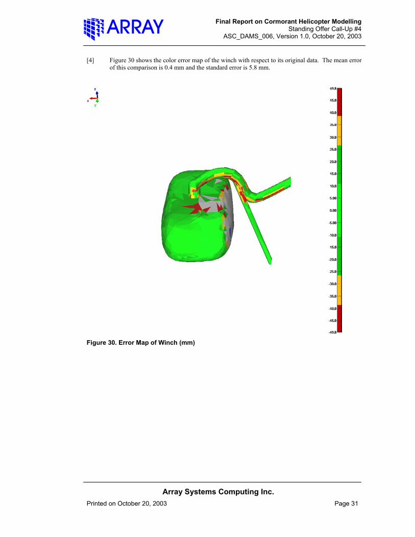
[4] Figure 30 shows the color error map of the winch with respect to its original data. The mean error of this comparison is 0.4 mm and the standard error is 5.8 mm.
Figure 30. Error Map of Winch (mm)

Final Report on Cormorant Helicopter Modelling Standing Offer Call-Up #4
ASC_DAMS_006, Version 1.0, October 20, 2003
Array Systems Computing Inc.
Printed on October 20, 2003 Page 32
[5] Figure 31 shows the color error map of the remaining exterior fixtures with respect to their original data. The mean error of this comparison is 0.8 mm and the standard error is 5.6 mm.
Figure 31. Error Map of Other External Fixtures (mm)

Final Report on Cormorant Helicopter Modelling Standing Offer Call-Up #4
ASC_DAMS_006, Version 1.0, October 20, 2003
Array Systems Computing Inc.
Printed on October 20, 2003 Page 33
3 FINAL MODEL AND DELIVERABLES [1] In addition to this report, there are three primary deliverables from this project.
3.1 Exterior Polygon Model [1] This file, named cormorant_ext_final.pol contains approximately 202946 Polygons, the result of
tolerance reduction to 1 mm. It also contains 13 logical polygon groups for various objects and areas like hull, windows, wheels, etc. One view of this model is presented in Figure 32.
Figure 32. Final Edited Polygon Model of Helicopter Exterior
Final Report on Cormorant Helicopter Modelling Standing Offer Call-Up #4
ASC_DAMS_006, Version 1.0, October 20, 2003
Array Systems Computing Inc.
Printed on October 20, 2003 Page 34
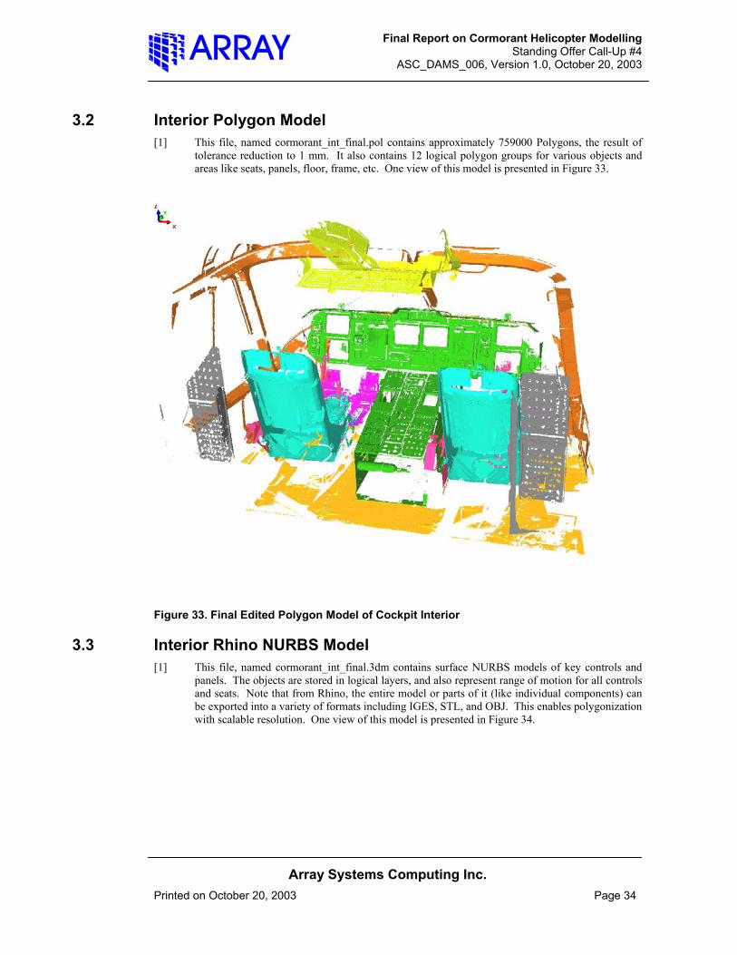
3.2 Interior Polygon Model [1] This file, named cormorant_int_final.pol contains approximately 759000 Polygons, the result of
tolerance reduction to 1 mm. It also contains 12 logical polygon groups for various objects and areas like seats, panels, floor, frame, etc. One view of this model is presented in Figure 33.
Figure 33. Final Edited Polygon Model of Cockpit Interior
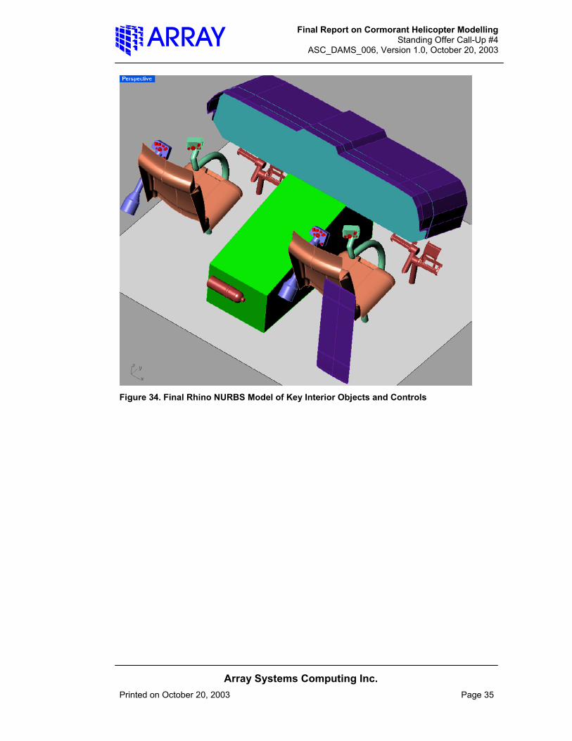
3.3 Interior Rhino NURBS Model [1] This file, named cormorant_int_final.3dm contains surface NURBS models of key controls and
panels. The objects are stored in logical layers, and also represent range of motion for all controls and seats. Note that from Rhino, the entire model or parts of it (like individual components) can be exported into a variety of formats including IGES, STL, and OBJ. This enables polygonization with scalable resolution. One view of this model is presented in Figure 34.
Final Report on Cormorant Helicopter Modelling Standing Offer Call-Up #4
ASC_DAMS_006, Version 1.0, October 20, 2003
Array Systems Computing Inc.
Printed on October 20, 2003 Page 35
Figure 34. Final Rhino NURBS Model of Key Interior Objects and Controls

Final Report on Cormorant Helicopter Modelling Standing Offer Call-Up #4
ASC_DAMS_006, Version 1.0, October 20, 2003
Array Systems Computing Inc.
Printed on October 20, 2003 Page 36
4 SUMMARY OF FINDINGS AND RECOMMENDATIONS [1] Three graphics models of the Cormorant helicopter were delivered for this call-up – the exterior,
interior, and key interior pilotage objects. These Polygon and NURBS surface models are scalable, and logically arranged in groups and/or layers. They also represent graphically the range of motions in the cockpit of the cyclics, collectives, pedals, and seats.
[2] An external mean accuracy of less than 1 millimetre (mm), and standard error of 4-6 mm for modelled areas of interest was verified with respect to the original data. An interior mean accuracy of less than 1 mm and standard error of 2-3 mm for modelled areas of interest was similarly verified. This is consistent and compatible with the accuracy of the laser scanners and their data.
[3] The following advanced techniques were used in the Cormorant modelling:
1. Polyworks rigorous alignment and best-fit least squares transformation operations 2. Extensive IMEdit surface reconstruction using Bezier surfaces 3. Extensive surface filtering and smoothing operations 4. Polyworks NURBS modelling for surface reconstruction 5. Rhino conventional NURBS surfacing 6. IMInspect verification of modelled surfaces and objects 7. Polyworks semi-automated edge reconstruction 8. Logical grouping and layering of objects and models 9. Definition of a suitable global model coordinate system 10. Extensive manual polygon editing and hole-filling 11. Polyworks IMCompress polygon model compression and tolerance reduction
[4] The following challenges were encountered and are discussed in this report:
1. Seat rail repositioning difficulty 2. Lack of symmetry in pilot/co-pilot cyclic scans 3. Lack of left to right symmetry in cyclic range of motions 4. Large undulations in fuzzy lower seat cushion 5. Areas of missing and/or noisy data in the external scans (underside of helicopter, areas of tail,
windows, etc.) 6. Lack of suitable automated hole-filling in Polyworks 7. Mirroring of interior ShapeGrabber data
[5] For future similar scanning projects the following is recommended:
1. Development of an improved seat locating process and fixtures (pins, blocks, etc.) with suitable shape variation and surface relief.
2. More complete scan coverage of external areas from more positions. 3. Video recording of measurement process for future use and archival information. 4. Exercising caution with ShapeGrabber orientation and calibration to avoid mirroring of data.
[6] For future modelling call-ups the following is recommended:
1. Additional liaison with Polyworks to resolve automated hole-filling difficulty. 2. One additional contractor/client meeting earlier in project.
Final Report on Cormorant Helicopter Modelling Standing Offer Call-Up #4
ASC_DAMS_006, Version 1.0, October 20, 2003
Array Systems Computing Inc.
Printed on October 20, 2003 Page 37
3. Increasing time budgets for Cyrax scan editing. 4. Continued and additional use and additional training of advanced Polyworks editing tools. 5. Revision and service pack updates of Polyworks and Rhino. 6. More investigation and/or use of photo-texturing for control panels and consoles. 7. On-site Internet access for technical support and access to knowledge bases.
DOCUMENT CONTROL DATA SHEET
1a. PERFORMING AGENCY Array Systems Computing, 1120 Finch Ave West, 7th floor, Toronto, Ontario, M3J3H7
2. SECURITY CLASSIFICATION
UNCLASSIFIED -
1b. PUBLISHING AGENCY DRDC Toronto
3. TITLE
(U) Final report on 3D modelling of the Cormorant helicopter
4. AUTHORS
Ray M. Obidowski
5. DATE OF PUBLICATION
October 24 , 2003
6. NO. OF PAGES
36
7. DESCRIPTIVE NOTES
8. SPONSORING/MONITORING/CONTRACTING/TASKING AGENCY Sponsoring Agency:Monitoring Agency:Contracting Agency : DRDC TorontoTasking Agency:
9. ORIGINATORS DOCUMENT NO.
Contract Report CR 2003-148
10. CONTRACT GRANT AND/OR PROJECT NO.
16ke12
11. OTHER DOCUMENT NOS.
12. DOCUMENT RELEASABILITY
Unlimited distribution
13. DOCUMENT ANNOUNCEMENT
Unlimited announcement
14. ABSTRACT
(U) This report describes the production of three graphics models of the Cormorant helicopter processed from laser scan data for both the helicopter exterior and cockpit interior. These Polygon and Non-Rational Uniform B-Spline (NURBS) surface models are scalable, and logically arranged in groups and/or layers. They also represent graphically the range of motions in the cockpit of the cyclics, collectives, pedals, and seats. An external mean accuracy of less than 1 millimetre (mm), and standard error of 4-6 mm for modelled areas of interest was verified with respect to the original data. An interior mean accuracy of less than 1 mm and standard error of 2-3 mm for modelled areas of interest was similarly verified. This accuracy is consistent and compatible with the accuracy of the laser scanners and their data.
(U) Le présent rapport décrit la production de trois modèles graphiques de l’hélicoptère Cormorant à partir de données obtenues par lecteur laser tant pour l’intérieur que pour l’extérieur de l’hélicoptère. Ces modèles de surface polygonaux et à B-spline non rationnelle uniforme (NURBS) sont vectorisés et organisés logiquement en groupes ou couches, ou les deux. Ils représentent aussi graphiquement la gamme des déplacements des manches cycliques, des leviers de pas collectif, des pédales et des sièges dans le poste de pilotage. Une précision moyenne à l’extérieur inférieure au millimètre (mm) et un écart-type compris entre 4 et 6 mm pour les zones modélisées dignes d’intérêt ont été obtenus à partir des données d’origine. Une précision moyenne à l’intérieur inférieure au milimètre et un écart-type compris entre 2 et 3 mm pour les zones modélisées dignes d’intérêt ont été obtenus de la même façon. Cette précision correspond à la précision des lecteurs laser et de leurs données et est compatible avec ceux-ci.
15. KEYWORDS, DESCRIPTORS or IDENTIFIERS
(U) 3D modelling, cormorant, helicopter