final binder - connection design briefs-compressed
DESCRIPTION
Final BinderTRANSCRIPT
PART-1-GENERAL TYPES
CONNECTION DESIGN BRIEFS CONFORMING TO BS-5950-1:2000
REVISION DATE MADE BY CHECKED BY APPROVED BY 0 JAN-05 MS SM MY
1

Client : Project : Estimate no : Contract no : Sheet no : TEMPLATE INDEX / 2
Date : DEC-05Calc'd by : MSChecked by : MY
---- 85C05/C2 - Conventional splice connection using flange and web plates
---- 81C05/C1 - Cap and base type connection
COLUMN SPLICE CONNECTIONS
---- 74C04/C2 - Base plate connection-Free stand analysis using MS-Excel and design using Master Series & Ms-Excel.
---- 69C04/C1 - Base plate connection design using mathcad
BASE PLATE CONNECTIONS
---- 62C03/C2 - Beam to beam end plate connection with UC plan brace
---- 53C03/C1 - RSA brace connecting with incoming beams using dragon-tie detail
HORIZONTAL BRACING CONNECTIONS
---- 42C02/C7 - Combined beam & vertical bracing connection - Gussets connected only with beam
---- 34C02/C6 - Combined beam & vertical bracing connection using wing plates
---- 27C02/C5 - Combined beam & vertical bracing connection
---- 22C02/C4 - UC Bracing bar with plates
---- 17C02/C3 - UC Bracing bar, flanges stripped and lapped on
---- 12C02/C2 - CHS/SHS Bracing bar with spade plate slotted into section - Cover plate detail
---- 7C02/C1 - CHS/SHS Bracing bar with spade plate slotted into section - Lapped on detail
REFERENCE PAGE NO.
VERTICAL BRACING CONNECTIONS
TEMPLATES FOR DESIGN / DESIGN BRIEF CONFORMING TO BS 5950-1:2000
Variation no: Rev date Description
2

Client : Project : Estimate no : Contract no : Sheet no : TEMPLATE INDEX / 3
Date : DEC-05Calc'd by : MSChecked by : MY
(MS-output Link)
---- 171C06/C11-Apex beam connection with horizontal bracings together with incoming beams
(PROKON output link)
---- 163C06/C10-Beam to column web moment connection using toe plate
---- 156C06/C9 - Beam to beam moment connection (Mz & My) with toe plate considering local eccentricities
---- 149C06/C8 - Moment connection with a haunch analysed using a couple force. Column stiffened
(MS-output link)
---- 134C06/C7 - Moment connection with a haunch analysed using rotation about centre line of flange. Column stiffened
---- 127C06/C6 - Moment connection without a haunch analysed using couple force. Column stiffened
---- 119C06/C5 - Moment connection without a haunch analysed using rotation about centre line of flange. Column stiffened
---- 112C06/C4 - Moment connection with a haunch analysed using a couple force. column unstiffened
(MS-output link)
---- 103C06/C3 - Moment connection with a haunch analysed using rotation about centre line of flange. Column unstiffened
---- 98C06/C2 - Moment connection without a haunch analysed using couple force. column unstiffened
(MS-output link)
---- 91C06/C1 - Moment connection without a haunch analysed using rotation about centre line of flange. Column unstiffened
REFERENCE PAGE NO.
MOMENT CONNECTIONS
Variation no: Rev date Description
3

Client : Project : Estimate no : Contract no : Sheet no : TEMPLATE INDEX / 4
Date : DEC-05Calc'd by : MSChecked by : MY
---- 227C09/C1 - Beam to RHS connection using PFC / welded plates
MISCELLANEOUS CONNECTIONS
---- 221C08/C6 - Beam to beam connection using toe plate with glut stiffener
---- 215C08/C5 - Beam to beam connection using toe plate
(PROKON output Link)
---- 208C08/C4 - Beam to beam connection using fin plate (Single sided)
---- 202C08/C3 - Beam to beam connection using end plate (Single sided & double sided)
---- 196C08/C2 - Beam to stiffened column web connection using fin plate (Single sided)
---- 189C08/C1 - Beam to stiffened column web connection using end plate (Single sided)
REFERENCE PAGE NO.SIMPLE CONNECTIONS USING e JOINT
C07/C1 - Beam to column flange connection using end plate ---- 182
C07/C2 - Beam to beam connection using end plate ---- 183
C07/C3 - Beam to column flange connection using fin plate ---- 184
C07/C4 - Beam to column web connection using fin plate ---- 185
C07/C5 - Beam to CHS column connection using fin plate ---- 186
C07/C6 - Beam to beam connection using fin plate ---- 187
C07/C7 - Beam to beam connection using welded tee plates ---- 188
SIMPLE CONNECTIONS USING MATHCAD
Variation no: Rev date Description
4
Client : Project : Estimate no : Contract no : Sheet no : TEMPLATE INDEX / 5
Date : DEC-05Calc'd by : MSChecked by : MY
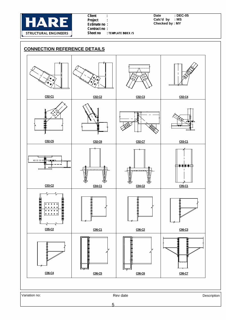
C02-C1 C02-C2 C02-C3 C02-C4
C02-C5 C02-C6 C02-C7 C03-C1
C03-C2 C04-C1 C04-C2 C05-C1
C05-C2 C06-C1 C06-C2 C06-C3
C06-C7C06-C6C06-C5C06-C4
CONNECTION REFERENCE DETAILS
Variation no: Rev date Description
5
Client : Project : Estimate no : Contract no : Sheet no : TEMPLATE INDEX / 6
Date : DEC-05Calc'd by : MSChecked by : MY
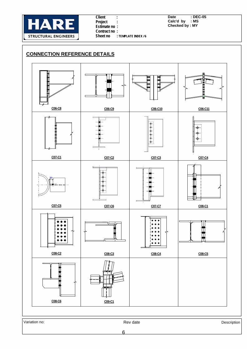
C06-C8 C06-C9 C06-C10 C06-C11
C07-C1 C07-C2 C07-C3 C07-C4
C07-C5 C07-C6 C07-C7 C08-C1
C08-C2 C08-C3 C08-C4 C08-C5
C09-C1C08-C6
CONNECTION REFERENCE DETAILS
Variation no: Rev date Description
6

Client : Project : Estimate no : Contract no : Sheet no : C02-C1/1
Date : DEC-05Calc'd by : MSChecked by : KP
CONNECTION -C02-C1 ( CHS/SHS Bracing bar with spade plate slotted into section - Lapped on detail )
BRACE CHS 219.1x8.0 F 200kN:=
219.1x8.0 CHS
250x15 THK SPADE PLATE
200kN
31°103kN
171.4kN15 THK
GUSSET PLATE
110
4070
40
350(MAX)
220
10
290(
MIN
)
UB
914
x305
x253
140(MIN)
NOTES:-
All bolts are M20, grade 8.8,
All welds are 6 mm CFW
All beams & fittings are grade S275
Variation no: Rev date Description
7

Client : Project : Estimate no : Contract no : Sheet no : C02-C1/2
Date : DEC-05Calc'd by : MSChecked by : KP
Material Properties
Design strength of S275 materialup to & including 16 mm thk
py275 275N
mm2⋅:=
Design strength of S275 materialbeyond 16 mm thk and up to and including 40mm thk
py265 265N
mm2⋅:=
Design strength of weld pw 220N
mm2⋅:=
Bracing
Diameter of brace bar Db 219.1 mm⋅:=
Thickness of brace bar tb 8 mm⋅:=
Diameter of bolt d 20mm:=
Diameter of hole Dh 22 mm=
No.of bolt rows nr 2:=
No of bolt columns nc 2:=
Total no. of bolts n 4=
Thickness of spade plate ts 15mm:=
Width of the spade plate ws 250mm:=
End distance local to free end ofspade plate
e1 40mm:=
Pitch p 70mm:=
Gauge g 110mm:=
Length of slot ls 220mm:=
Net area coefficient Ke 1.2:=
Check for Bolts
Check for shear capacity
Shear capacity of bolt Ps 91.9kN:=
Shear per bolt FsFn
:= Fs 50.00 kN=
Ps (91.9 kN) > Fs (50 kN): Therefore O.k
Variation no: Rev date Description
8
Client : Project : Estimate no : Contract no : Sheet no : C02-C1/3
Date : DEC-05Calc'd by : MSChecked by : KP
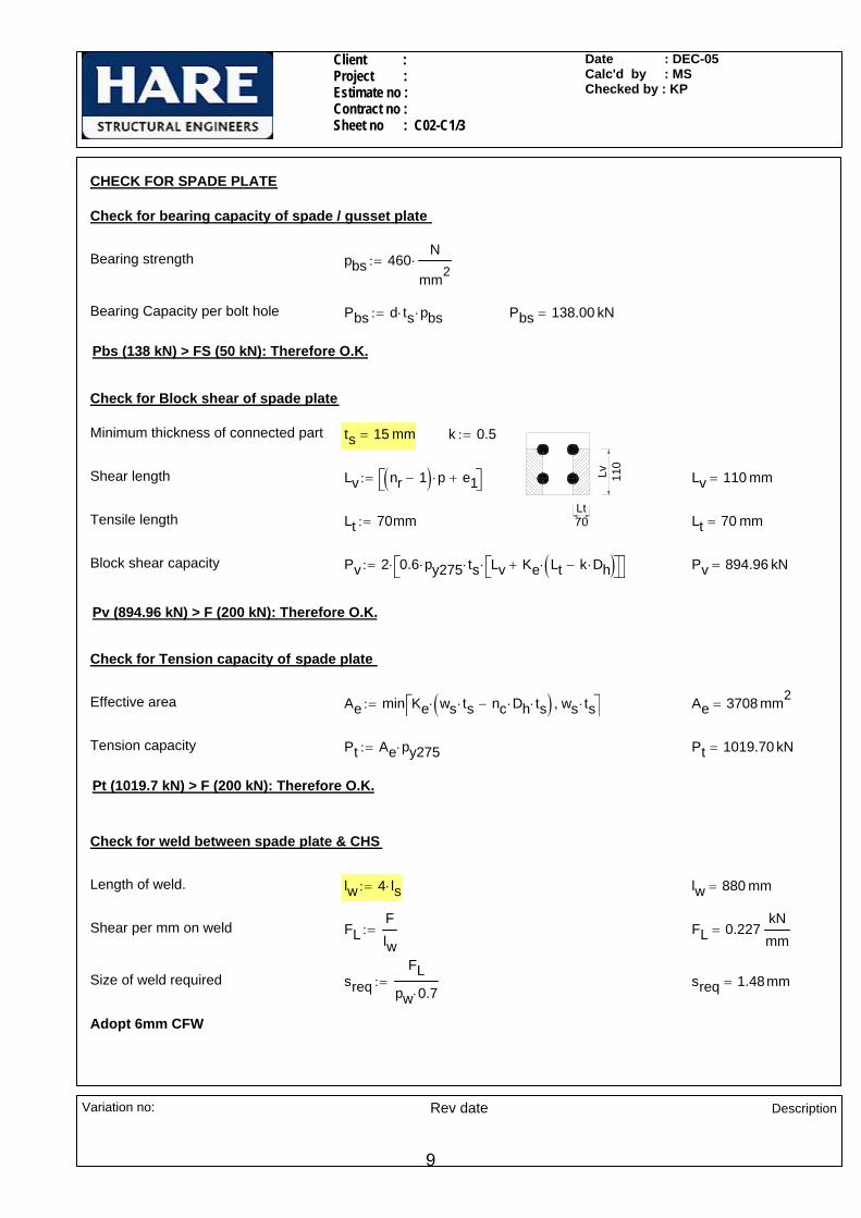
CHECK FOR SPADE PLATE
Check for bearing capacity of spade / gusset plate
Bearing strength pbs 460N
mm2⋅:=
Bearing Capacity per bolt hole Pbs d ts⋅ pbs⋅:= Pbs 138.00 kN=
Pbs (138 kN) > FS (50 kN): Therefore O.K.
Check for Block shear of spade plate
Lt
Lv 110
Minimum thickness of connected part ts 15 mm= k 0.5:=
Shear length Lv nr 1−( ) p⋅ e1+⎡⎣ ⎤⎦:= Lv 110 mm=
Tensile length Lt 70mm:= Lt 70 mm=
Block shear capacity Pv 2 0.6 py275⋅ ts⋅ Lv Ke Lt k Dh⋅−( )⋅+⎡⎣ ⎤⎦⋅⎡⎣ ⎤⎦⋅:= Pv 894.96 kN=
Pv (894.96 kN) > F (200 kN): Therefore O.K.
Check for Tension capacity of spade plate
Effective area Ae min Ke ws ts⋅ nc Dh⋅ ts⋅−( )⋅ ws ts⋅,⎡⎣ ⎤⎦:= Ae 3708 mm2=
Tension capacity Pt Ae py275⋅:= Pt 1019.70 kN=
Pt (1019.7 kN) > F (200 kN): Therefore O.K.
Check for weld between spade plate & CHS
Length of weld. lw 4 ls⋅:= lw 880 mm=
Shear per mm on weld FLFlw
:= FL 0.227kNmm
=
Size of weld required sreqFL
pw 0.7⋅:= sreq 1.48mm=
Adopt 6mm CFW
Variation no: Rev date Description
9
Client : Project : Estimate no : Contract no : Sheet no : C02-C1/4
Date : DEC-05Calc'd by : MSChecked by : KP
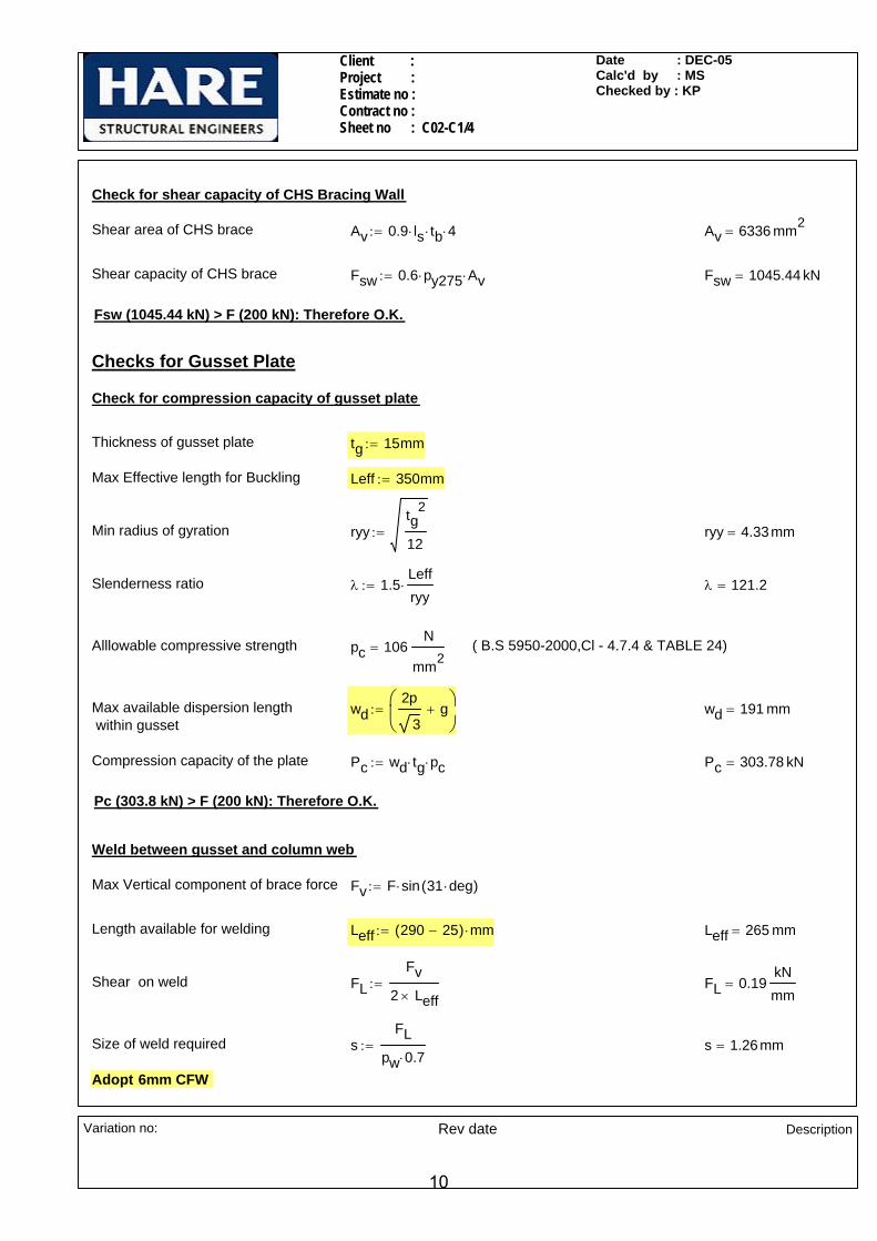
Check for shear capacity of CHS Bracing Wall
Shear area of CHS brace Av 0.9 ls⋅ tb⋅ 4⋅:= Av 6336 mm2=
Shear capacity of CHS brace Fsw 0.6 py275⋅ Av⋅:= Fsw 1045.44 kN=
Fsw (1045.44 kN) > F (200 kN): Therefore O.K.
Checks for Gusset Plate
Check for compression capacity of gusset plate
Thickness of gusset plate tg 15mm:=
Max Effective length for Buckling Leff 350mm:=
Min radius of gyration ryytg
2
12:= ryy 4.33mm=
Slenderness ratio λ 1.5Leffryy
⋅:= λ 121.2=
Alllowable compressive strength pc 106N
mm2= ( B.S 5950-2000,Cl - 4.7.4 & TABLE 24)
Max available dispersion length within gusset
wd2p
3g+
⎛⎜⎝
⎞⎠
:= wd 191 mm=
Compression capacity of the plate Pc wd tg⋅ pc⋅:= Pc 303.78 kN=
Pc (303.8 kN) > F (200 kN): Therefore O.K.
Weld between gusset and column web
Max Vertical component of brace force Fv F sin 31 deg⋅( )⋅:=
Length available for welding Leff 290 25−( ) mm⋅:= Leff 265 mm=
Shear on weld FLFv
2 Leff×:= FL 0.19
kNmm
=
Size of weld required sFL
pw 0.7⋅:= s 1.26mm=
Adopt 6mm CFW
Variation no: Rev date Description
10

Client : Project : Estimate no : Contract no : Sheet no : C02-C1/5
Date : DEC-05Calc'd by : MSChecked by : KP
Weld between gusset plate and baseplate
Max Horizontal component of brace force
Fh F cos 31 deg⋅( )⋅:= Fh 171.43 kN=
Length available for welding Leff 140mm 25mm−:= Leff 115 mm=
Shear on weld FLFh
2 Leff×:= FL 0.745
kNmm
=
Size of weld required sFL
pw 0.7⋅:= s 4.84mm=
Adopt 6mm CFW
Variation no: Rev date Description
11

Client : Project : Estimate no : Contract no : Sheet no : C02-C2/1
Date : DEC-05Calc'd by : MSChecked by : KP
CONNECTION -C02-C2 ( CHS/SHS Bracing bar with spade plate slotted into section - Using cover plates )
BRACE CHS 219.1x8.0 F 200kN:=
10
250x15 THK SPADE PLATE
15 THK GUSSET PLATE
40 40
4040
110
31°
200kN
171.4kN
103kN
2 NOS 250 X 10 THK COVER PLATE
CHS 219.1 X 8
250(
MIN
)
UB
914
x305
x253
300(MAX)
10
140(MIN)
220
NOTES:-
All bolts are M20, grade 8.8,
All welds are 6 mm CFW
All beams & fittings are grade S275
Variation no: Rev date Description
12

Client : Project : Estimate no : Contract no : Sheet no : C02-C2/2
Date : DEC-05Calc'd by : MSChecked by : KP
Material Properties
Design strength of S275 materialup to & including 16 mm thk
py275 275N
mm2⋅:=
Design strength of S275 materialbeyond 16 mm thk and up to and including 40mm thk
py265 265N
mm2⋅:=
Design strength of weld pw 220N
mm2⋅:=
Bracing
Diameter of brace bar Db 219.1 mm⋅:=
Thickness of brace bar tb 8 mm⋅:=
Diameter of bolt d 20mm:=
Diameter of hole Dh 22 mm=
No.of bolt rows nr 1:=
No of bolt columns nc 2:=
Total no. of bolts n 2=
Width of the spade / cover plate ws 250mm:=
Thickness of spade plate ts 15mm:=
Thickness of cover plate tc 10mm:=
End distance local to free end ofspade plate
e1 40mm:=
Gauge g 110mm:=
Length of slot ls 220mm:=
Net area coefficient Ke 1.2:=
Check for Bolts
Check for shear capacity
Shear capacity of bolt Ps 91.9kN:= Ps 91.90 kN=
Shear per bolt on double plane FsF
2 n⋅:= Fs 50 kN=
Ps (91.9 kN) > Fs (50 kN): Therefore O.k
Variation no: Rev date Description
13

Client : Project : Estimate no : Contract no : Sheet no : C02-C2/3
Date : DEC-05Calc'd by : MSChecked by : KP
Check for bearing capacity of spade / gusset / cover plate
Bearing strength pbs 460N
mm2⋅:=
Bearing Capacity per bolt hole Pbs d ts⋅ pbs⋅:= Pbs 138.00 kN=
Pbs (138 kN) > FS (50 kN): Therefore O.K.
Check for Tension capacity of spade plate
Effective area Ae min Ke ws ts⋅ nc Dh⋅ ts⋅−( )⋅ ws ts⋅,⎡⎣ ⎤⎦:= Ae 3708 mm2=
Tension capacity Pt Ae py275⋅:= Pt 1019.70 kN=
Pt (1019.7 kN) > F (200 kN): Therefore O.K.
Check for weld between spade plate & CHS
Length of weld. lw 4 ls⋅:= lw 880 mm=
Shear per mm on weld FLFlw
:= FL 0.227kNmm
=
Size of weld required sreqFL
pw 0.7⋅:= sreq 1.48mm=
Adopt 6mm CFW
Check for compression capacity of cover plate
110
40 40 40 40
10
90
Thickness of cover plate tc 10 mm=
Max Effective length for Buckling Leff 90mm:=
Min radius of gyration ryytc
2
12:= ryy 2.89mm=
Slenderness ratio λ 1.5Leffryy
⋅:= λ 46.8=
Alllowable compressive strength pc 241N
mm2= ( B.S 5950-2000,Cl - 4.7.4 & TABLE 24)
Max available dispersion length wd 110mm:=
Compression capacity of cover plates Pc 2wd tc⋅ pc⋅:= Pc 530.62 kN=
Pc (530.6 kN) > F (200 kN): Therefore O.K.
Therefore adopt 2Nos 10 thk cover plate
Variation no: Rev date Description
14

Client : Project : Estimate no : Contract no : Sheet no : C02-C2/4
Date : DEC-05Calc'd by : MSChecked by : KP
Check for shear capacity of CHS Bracing Wall
Shear area of CHS brace Av 0.9 ls⋅ tb⋅ 4⋅:= Av 6336 mm2=
Shear capacity of CHS brace Fsw 0.6 py275⋅ Av⋅:= Fsw 1045.44 kN=
Fsw (1045.44 kN) > F (200 kN): Therefore O.K.
Checks for Gusset Plate
Check for compression capacity of gusset plate
Thickness of gusset plate tg 15mm:=
Max Effective length for Buckling Leff 300mm:=
Min radius of gyration ryytg
2
12:= ryy 4.33mm=
Slenderness ratio λ 1.5Leffryy
⋅:= λ 103.9=
Alllowable compressive strength pc 134N
mm2= ( B.S 5950-2000,Cl - 4.7.4 & TABLE 24)
Max available dispersion length within gusset
wd 110mm:=
Compression capacity of the plate Pc wd tg⋅ pc⋅:= Pc 220.43 kN=
Pc (220.4 kN) > F (200 kN): Therefore O.K.
Weld between gusset and column web
Max Vertical component of brace force Fv F sin 31 deg⋅( )⋅:= Fv 103.01 kN=
Length available for welding Leff 250 25−( ) mm⋅:= Leff 225 mm=
Shear on weld FLFv
2 Leff×:= FL 0.23
kNmm
=
Size of weld required sFL
pw 0.7⋅:= s 1.49mm=
Adopt 6mm CFW
Variation no: Rev date Description
15

Client : Project : Estimate no : Contract no : Sheet no : C02-C2/5
Date : DEC-05Calc'd by : MSChecked by : KP
Weld between gusset plate and baseplate
Max Horizontal component of brace force
Fh F cos 31 deg⋅( )⋅:= Fh 171.43 kN=
Length available for welding Leff 140mm 25mm−:= Leff 115 mm=
Shear on weld FLFh
2 Leff×:= FL 0.745
kNmm
=
Size of weld required sFL
pw 0.7⋅:= s 4.84mm=
Adopt 6mm CFW
Variation no: Rev date Description
16

Client : Project : Estimate no : Contract no : Sheet no : C02-C3 / 1
Date : DEC-05Calc'd by : SSKChecked by : KP
CONNECTION - C02-C3 (UC bracing bar,flanges stripped and lapped on)
Axial force in brace member F 286kN:=
(TYP
)
320(
MAX
)
115
(TYP
)
(TYP
)
W.P
10
40
(MIN
)20
20 THK. GUSSET PLATE
HE24
0A(T
YP.)
HE 240 A
OF HE240A(TYP.)STRIP FLANGES N/S
7070
40
600(MIN)
90(TYP)
ANGLE B/W 38 ° 225 kN(MAX)
(TYP)
(TYP)AND 62 °
253 kN(MAX)
286 kN (TYP)
NOTES:-
All bolts are M20. Grade 8.8.
All welds are 6mm CFW
All main steel & fittings are S275
Variation no: Rev date Description
17

Client : Project : Estimate no : Contract no : Sheet no : C02-C3 / 2
Date : DEC-05Calc'd by : SSKChecked by : KP
Sectional Properties
Bracing HE 240A w 240 mm⋅:= tf 12mm:= tw 7.5 mm⋅:= D 230mm:= rb 21mm:= Abr 7680mm2:=
Material Properties
Design strength of S275 materialup to and including 16 thk
py275 275N
mm2⋅:=
Design strength of S275 materialbeyond 16thk, up to and including 40mm thk
py265 265N
mm2⋅:=
Design strength of weld pw 220N
mm2⋅:=
Diameter of bolt db 20mm:=
Diameter of hole Dh 22 mm=
Shear capacity of bolt Ps 91.9kN:=
End distance et 40mm:=
Pitch p 70mm:=
Gauge g 90mm:=
No of bolt rows nr 3:=
No of bolt columns nc 2:=
Total no of bolts n 6=
Check for bolts
Shear load on each Bolt FsFn
:= Fs 47.7kN=
Ps (91.9 kN) > Fs (47.67 kN): Therefore O.K.
Check for bearing
Minimum thickness of connected ply tw 7.5 mm=
Bearing strength pbs 460N
mm2⋅:=
Bearing Capacity Pbs db tw⋅ pbs⋅ n⋅:= Pbs 414 kN=
Pbs (414 kN) > F (286 kN): Therefore O.K.
Variation no: Rev date Description
18

Client : Project : Estimate no : Contract no : Sheet no : C02-C3 / 3
Date : DEC-05Calc'd by : SSKChecked by : KP
Check for brace bar
et
p
p
g
Block shear capacity of brace bar
Net area coefficient for S275
ke 1.2:= k 1:=
Lv et nr 1−( ) p⋅+:= Lv 180 mm=Shear length
Lt g:= Lt 90 mm=Tensile length
Block Shear capacity Pr 0.6 py275⋅ tw⋅ 2Lv ke Lt k Dh⋅−( )⋅+⎡⎣ ⎤⎦⋅:= Pr 546.5 kN=
Pr (546.5 kN) > F (286 kN): Therefore O.K.
Reduced tension capacity of brace bar
Area - root radius Ar2.rb( )2 π rb
2⋅−
4:= Ar 94.6mm2
=
Reduced gross area Ag Abr 2 w tw−( ) 0.5⋅⎡⎣ ⎤⎦⋅ tf⋅− 2Ar−:= Ag 4700.7 mm2=
Net area An Ag 2 Dh⋅ tw⋅−( ) ke⋅:= An 5244.9 mm2=
Effective area Ae min Ag An,( ):= Ae 4700.7 mm2=
a2 Ag D tw⋅−:= a2 2975.7 mm2=
Tension capacity PT py275 Ae 0.5 a2⋅−( )⋅:= PT 883.5 kN=
PT (883.5 kN) > F (286 kN): Therefore O.K.
Check for gusset
Check for compression capacity of gusset plate
Thickness of gusset plate tg 20mm:=
Max Effective length for Buckling Leff 320mm:=
Min radius of gyration ryytg
2
12:= ryy 5.8 mm=
Variation no: Rev date Description
19
Client : Project : Estimate no : Contract no : Sheet no : C02-C3 / 4
Date : DEC-05Calc'd by : SSKChecked by : KP
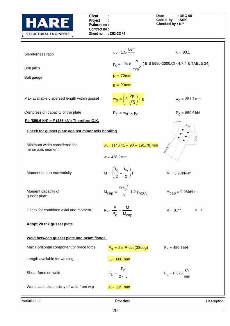
λ 1.5Leffryy
⋅:= λ 83.1=Slenderness ratio
pc 170.8N
mm2= ( B.S 5950-2000,Cl - 4.7.4 & TABLE 24)
Bolt pitch
p 70mm:=Bolt gauge
g 90mm:=
Max available dispersed length within gusset wd 22p
3⋅
⎛⎜⎝
⎞⎠
g+:= wd 251.7 mm=
Compression capacity of the plate Pc wd tg⋅ pc⋅:= Pc 859.6 kN=
Pc (859.6 kN) > F (286 kN): Therefore O.K.
HE24
0A(T
YP.)
146.41
90.00
191.
78
Check for gusset plate against minor axis bending
Minimum width considered for minor axis moment
w 146.41 90+ 191.78+( )mm:=
w 428.2 mm=
Moment due to eccentricity Mtg2
tw2
+⎛⎜⎝
⎞
⎠F⋅:= M 3.93kN m⋅=
Moment capacity of gusset plate
Mcapw tg
2⋅
61.2⋅ py265⋅:= Mcap 9.08kN m⋅=
Check for combined axial and moment RF
Pc
MMcap
+:= R 0.77= < 1
Adopt 20 thk gusset plate
Weld between gusset plate and beam flange
Max Horizontal component of brace force Fh 2 F× cos 38deg( )⋅:= Fh 450.7 kN=
Length available for welding L 600 mm⋅:=
Shear force on weld FLFh
2 L×:= FL 0.376
kNmm
=
Worst case eccentricity of weld from w.p e 115 mm⋅:=
Variation no: Rev date Description
20

Client : Project : Estimate no : Contract no : Sheet no : C02-C3 / 5
Date : DEC-05Calc'd by : SSKChecked by : KP
Moment due to eccentricity M Fh e⋅:= M 51.8kN m⋅=
FTM 6⋅
2 L2⋅
:= FT 0.432kNmm
=Tensile force on weld
Resultant force on weld RFT
1.25
⎛⎜⎝
⎞
⎠
2
FL2
+:= R 0.51kNmm
=
Size of weld required sR
pw 0.7⋅:= s 3.314 mm=
Adopt 6mm CFW
Variation no: Rev date Description
21

Client : Project : Estimate no : Contract no : Sheet no : C02-C4 / 1
Date : DEC-05Calc'd by : MSChecked by : KP
4070
7090
7040
70
60
10
UC 152X
152X
30
167.4 kN
230.
4 kN
266 k
N
ANGLE VARIES FROM 51 TO 60
OO
(MAX
)
(MAX)
UC 2
54X2
54X7
3
GUSSET 15 THK
(PACK PLATES TO SUIT)2 Nos. 120 X 10 THK COVER PLATES
W.P.
250(M
AX)
400(
MIN
)
SNIPES 10X10
20(MIN)
140(MIN)
A
A
CONNECTION -C02-C4 ( UC bracing bar,with cover plates )
Axial force in brace member F 266kN:=
PACKS TO SUIT
SECTION A-A
152 UC 30 WEB
GUSSET
NOTES:-
All bolts are M20. Grade 8.8.
All welds are 6 CFW.
All main steel & fittings are S275.
Variation no: Rev date Description
22

Client : Project : Estimate no : Contract no : Sheet no : C02-C4 / 2
Date : DEC-05Calc'd by : MSChecked by : KP
Sectional Properties
Bracing UC 152 X 152 X 30
Dbr 157.6mm:= Wbr 152.9 mm⋅:= tbr 6.5mm:= Tbr 9.4 mm⋅:= rbr 7.6 mm⋅:= Abr 3830mm2:=
Material Properties
Design strength of S275 materialup to and including 16 thk
py275 275N
mm2⋅:=
Design strength of S275 materialbeyond 16thk, up to and including 40mm thk
py265 265N
mm2⋅:=
Bearing Strength of S275 material pbs 460
N
mm2:=
Design strength of weld pw 220N
mm2⋅:=
Bolt properties in brace bar
Bolt Diameter d 20 mm⋅:=
Diameter of hole Dh 22mm:=
No of bolt rows nr 3:=
No of bolt columns nc 2:=
Total no. of bolts n 6=
End distance et 40mm:=
Edge distance e2 30mm:=
Gauge g 60mm:=
Pitch p 70mm:=
Shear capacity of M20 bolt Ps 91.9kN:=
Tension capacity of M20 bolt Pnom 110kN:=
Variation no: Rev date Description
23
Client : Project : Estimate no : Contract no : Sheet no : C02-C4 / 3
Date : DEC-05Calc'd by : MSChecked by : KP
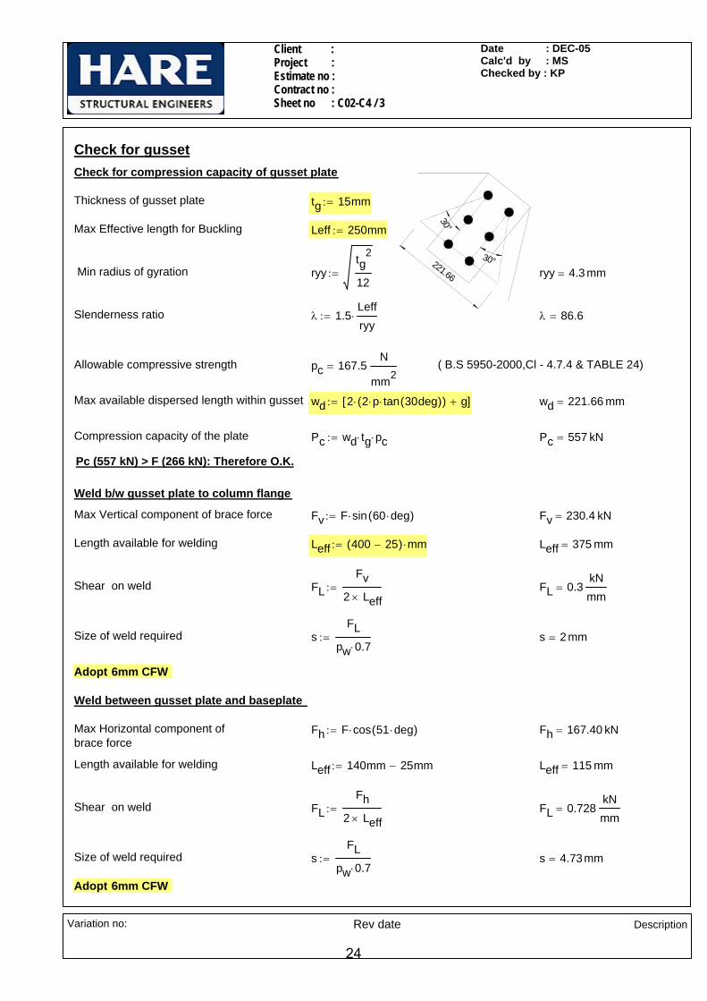
Check for gusset
30°30°221.66
Check for compression capacity of gusset plate
Thickness of gusset plate tg 15mm:=
Max Effective length for Buckling Leff 250mm:=
Min radius of gyration ryytg
2
12:= ryy 4.3 mm=
Slenderness ratio λ 1.5Leffryy
⋅:= λ 86.6=
Allowable compressive strength pc 167.5N
mm2= ( B.S 5950-2000,Cl - 4.7.4 & TABLE 24)
Max available dispersed length within gusset wd 2 2 p⋅ tan 30deg( )⋅( )⋅ g+[ ]:= wd 221.66 mm=
Compression capacity of the plate Pc wd tg⋅ pc⋅:= Pc 557 kN=
Pc (557 kN) > F (266 kN): Therefore O.K.
Weld b/w gusset plate to column flange
Max Vertical component of brace force Fv F sin 60 deg⋅( )⋅:= Fv 230.4 kN=
Length available for welding Leff 400 25−( ) mm⋅:= Leff 375 mm=
Shear on weld FLFv
2 Leff×:= FL 0.3
kNmm
=
Size of weld required sFL
pw 0.7⋅:= s 2 mm=
Adopt 6mm CFW
Weld between gusset plate and baseplate
Max Horizontal component of brace force
Fh F cos 51 deg⋅( )⋅:= Fh 167.40 kN=
Length available for welding Leff 140mm 25mm−:= Leff 115 mm=
Shear on weld FLFh
2 Leff×:= FL 0.728
kNmm
=
Size of weld required sFL
pw 0.7⋅:= s 4.73mm=
Adopt 6mm CFW
Variation no: Rev date Description
24

Client : Project : Estimate no : Contract no : Sheet no : C02-C4 / 4
Date : DEC-05Calc'd by : MSChecked by : KP
Check for brace bar (UC 152x152x30)
Check for bolts between brace and gusset
Shear load on each bolt per shear plane FsF2n
:= Fs 22.2kN=Ps (91.9 kN) > Fs (22.17 kN): Therefore O.K.
Check for bolts in bearing
Minimum thickness of connected part tbr 6.5 mm=
Bearing Capacity Pbs d tbr⋅ pbs⋅ n⋅:= Pbs 358.8 kN=Pbs (358.8 kN) > F (266 kN): Therefore O.K.
et
p
p
e2gBlock shear capacity of web cover plate/brace bar
Pattern 1:
Net area coefficient for S275
ke 1.2:= k 2.5:=
Web cover plate thickness twp 10mm:=
Shear length Lv et nr 1−( ) p⋅+:= Lv 180 mm=
Lt g e2+:= Lt 90 mm=Tensile length
Block Shear capacity Pr 2 0.6 py275⋅ twp⋅⋅ Lv ke Lt k Dh⋅−( )⋅+⎡⎣ ⎤⎦⋅:= Pr 732.6 kN=
Pr (732.6 kN) > F (266 kN): Therefore O.K.
et
p
p
gPattern 2:
Net area coefficient for S275
ke 1.2:= k 1:=
Lv 2 et nr 1−( ) p⋅+⎡⎣ ⎤⎦⋅:= Lv 360 mm=Shear length
Lt g:= Lt 60 mm=Tensile length
Block Shear capacity Pr 0.6 py275⋅ tbr⋅ Lv ke Lt k Dh⋅−( )⋅+⎡⎣ ⎤⎦⋅:= Pr 435 kN=
Pr (435 kN) > F (266 kN): Therefore O.K.
Variation no: Rev date Description
25
Client : Project : Estimate no : Contract no : Sheet no : C02-C4 / 5
Date : DEC-05Calc'd by : MSChecked by : KP
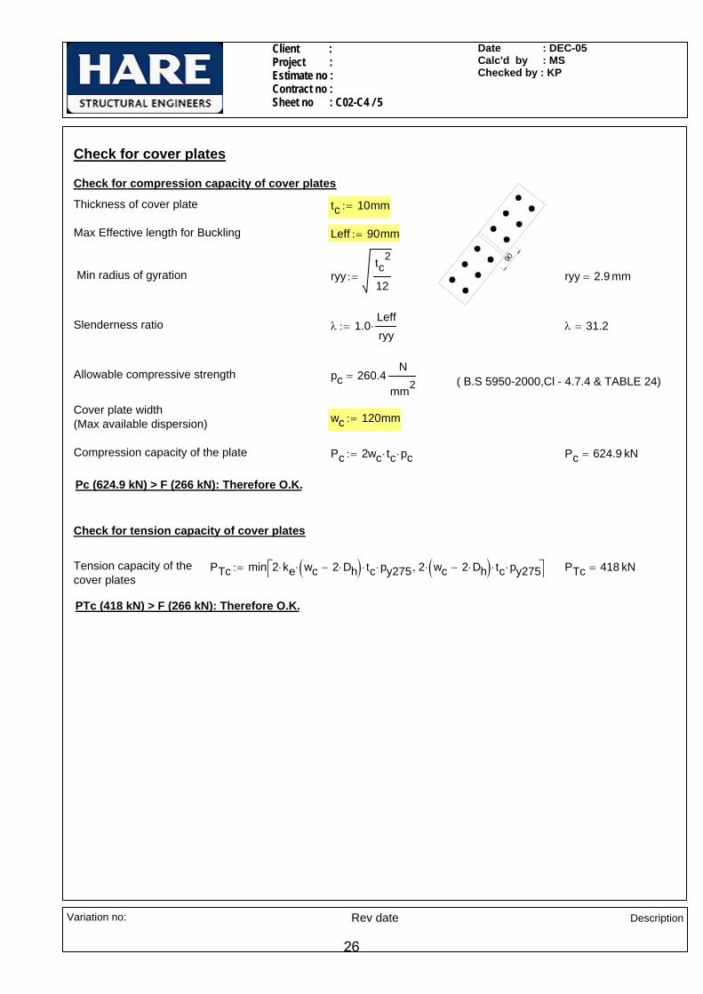
Check for cover plates
90
Check for compression capacity of cover plates
Thickness of cover plate tc 10mm:=
Max Effective length for Buckling Leff 90mm:=
Min radius of gyration ryytc
2
12:= ryy 2.9 mm=
Slenderness ratio λ 1.0Leffryy
⋅:= λ 31.2=
Allowable compressive strength pc 260.4N
mm2= ( B.S 5950-2000,Cl - 4.7.4 & TABLE 24)
Cover plate width(Max available dispersion) wc 120mm:=
Compression capacity of the plate Pc 2wc tc⋅ pc⋅:= Pc 624.9 kN=
Pc (624.9 kN) > F (266 kN): Therefore O.K.
Check for tension capacity of cover plates
Tension capacity of the cover plates
PTc min 2 ke wc 2 Dh⋅−( )⋅ tc⋅⋅ py275⋅ 2 wc 2 Dh⋅−( ) tc⋅⋅ py275⋅,⎡⎣ ⎤⎦:= PTc 418 kN=
PTc (418 kN) > F (266 kN): Therefore O.K.
Variation no: Rev date Description
26
Client : Project : Estimate no : Contract no : Sheet no : C02-C5 / 1
Date : DEC-05Calc'd by : SSKChecked by : KP
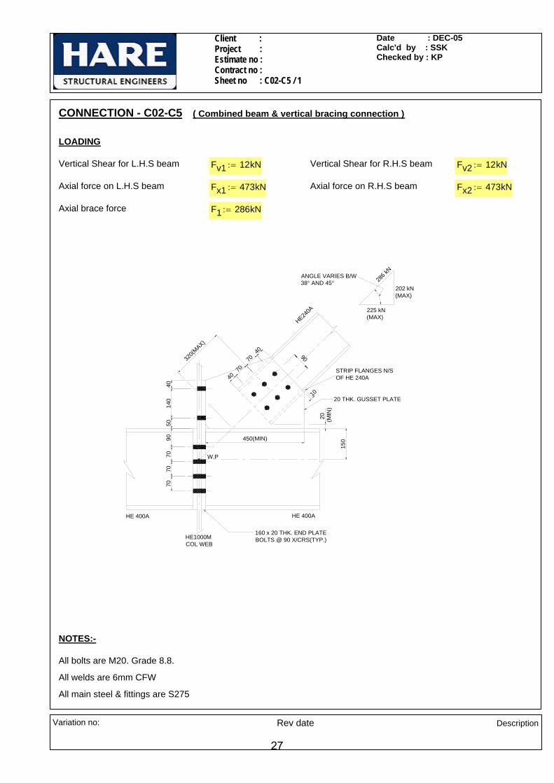
CONNECTION - C02-C5 ( Combined beam & vertical bracing connection )
LOADING
Vertical Shear for L.H.S beam Fv1 12kN:= Vertical Shear for R.H.S beam Fv2 12kN:=
Axial force on L.H.S beam Fx1 473kN:= Axial force on R.H.S beam Fx2 473kN:=
Axial brace force F1 286kN:=
W.P
10
HE240A
286 k
N
20 THK. GUSSET PLATE
160 x 20 THK. END PLATEBOLTS @ 90 X/CRS(TYP.)
HE 400AHE 400A
4050
40
70
70
40
7070
7090
140
HE1000MCOL WEB
(MIN
)20
150
STRIP FLANGES N/SOF HE 240A
450(MIN)
320(M
AX)
ANGLE VARIES B/W 38° AND 45°
202 kN(MAX)
225 kN(MAX)
90
NOTES:-
All bolts are M20. Grade 8.8.
All welds are 6mm CFW
All main steel & fittings are S275
Variation no: Rev date Description
27
Client : Project : Estimate no : Contract no : Sheet no : C02-C5 / 2
Date : DEC-05Calc'd by : SSKChecked by : KP
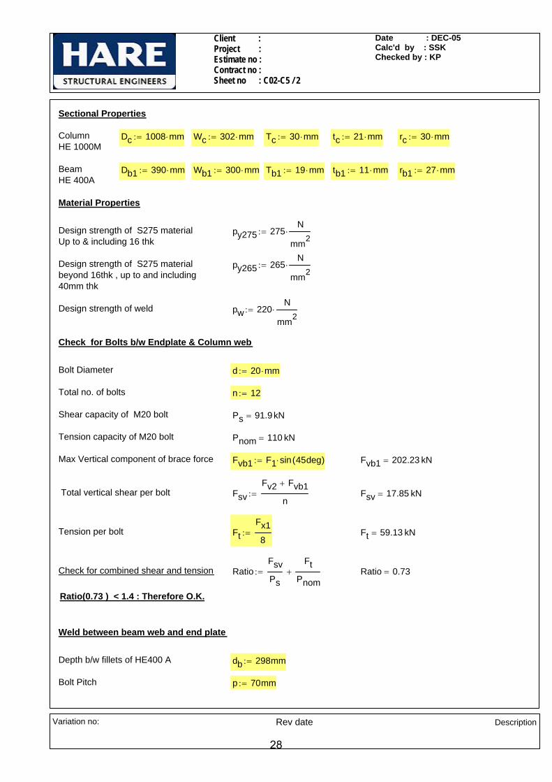
Sectional Properties
Column HE 1000M
Dc 1008 mm⋅:= Wc 302 mm⋅:= Tc 30 mm⋅:= tc 21 mm⋅:= rc 30 mm⋅:=
Beam HE 400A
Db1 390 mm⋅:= Wb1 300 mm⋅:= Tb1 19 mm⋅:= tb1 11 mm⋅:= rb1 27 mm⋅:=
Material Properties
Design strength of S275 materialUp to & including 16 thk
py275 275N
mm2⋅:=
Design strength of S275 materialbeyond 16thk , up to and including 40mm thk
py265 265N
mm2⋅:=
Design strength of weld pw 220N
mm2⋅:=
Check for Bolts b/w Endplate & Column web
Bolt Diameter d 20 mm⋅:=
Total no. of bolts n 12:=
Shear capacity of M20 bolt Ps 91.9kN=
Tension capacity of M20 bolt Pnom 110 kN=
Max Vertical component of brace force Fvb1 F1 sin 45deg( )⋅:= Fvb1 202.23 kN=
Total vertical shear per bolt FsvFv2 Fvb1+
n:= Fsv 17.85 kN=
Tension per bolt FtFx18
:= Ft 59.13 kN=
Check for combined shear and tension RatioFsvPs
FtPnom
+:= Ratio 0.73=
Ratio(0.73 ) < 1.4 : Therefore O.K.
Weld between beam web and end plate
Depth b/w fillets of HE400 A db 298mm:=
Bolt Pitch p 70mm:=
Variation no: Rev date Description
28
Client : Project : Estimate no : Contract no : Sheet no : C02-C5 / 3
Date : DEC-05Calc'd by : SSKChecked by : KP
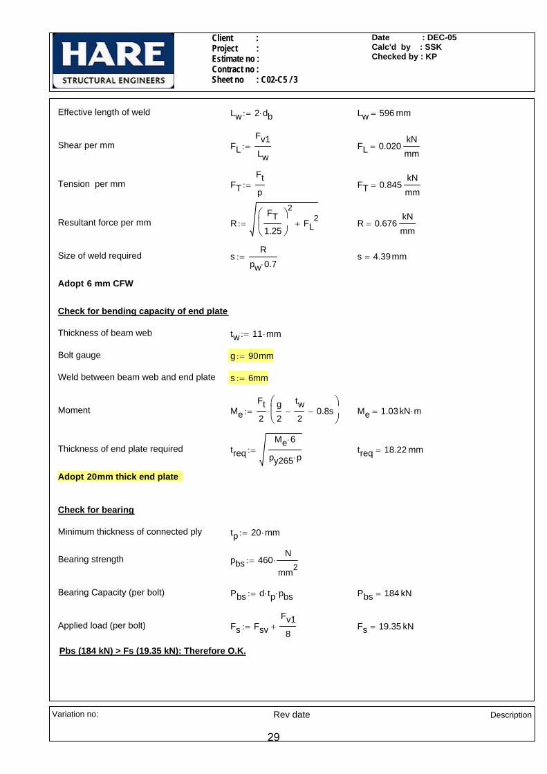
Effective length of weld Lw 2 db⋅:= Lw 596 mm=
Shear per mm FLFv1Lw
:= FL 0.020kNmm
=
Tension per mm FTFtp
:= FT 0.845kNmm
=
Resultant force per mm RFT
1.25
⎛⎜⎝
⎞
⎠
2
FL2
+:= R 0.676kNmm
=
Size of weld required sR
pw 0.7⋅:= s 4.39mm=
Adopt 6 mm CFW
Check for bending capacity of end plate
Thickness of beam web tw 11 mm⋅:=
Bolt gauge g 90mm:=
Weld between beam web and end plate s 6mm:=
Moment MeFt2
g2
tw2
− 0.8s−⎛⎜⎝
⎞
⎠⋅:= Me 1.03kN m⋅=
Thickness of end plate required treqMe 6⋅
py265 p⋅:= treq 18.22 mm=
Adopt 20mm thick end plate
Check for bearing
Minimum thickness of connected ply tp 20 mm⋅:=
Bearing strength pbs 460N
mm2⋅:=
Bearing Capacity (per bolt) Pbs d tp⋅ pbs⋅:= Pbs 184 kN=
Applied load (per bolt) Fs FsvFv18
+:= Fs 19.35 kN=
Pbs (184 kN) > Fs (19.35 kN): Therefore O.K.
Variation no: Rev date Description
29
Client : Project : Estimate no : Contract no : Sheet no : C02-C5 / 4
Date : DEC-05Calc'd by : SSKChecked by : KP
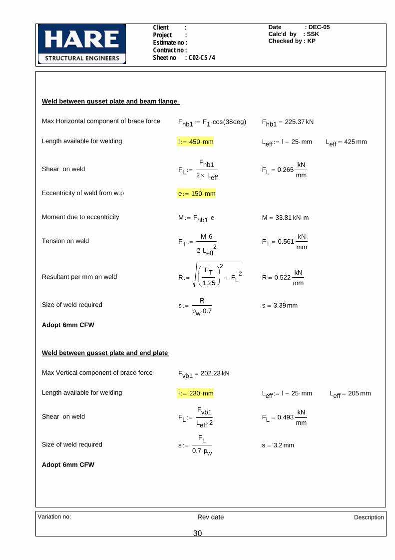
Weld between gusset plate and beam flange
Max Horizontal component of brace force Fhb1 F1 cos 38deg( )⋅:= Fhb1 225.37 kN=
Length available for welding l 450 mm⋅:= Leff l 25 mm⋅−:= Leff 425 mm=
Shear on weld FLFhb1
2 Leff×:= FL 0.265
kNmm
=
Eccentricity of weld from w.p e 150 mm⋅:=
Moment due to eccentricity M Fhb1 e⋅:= M 33.81 kN m⋅=
Tension on weld FTM 6⋅
2 Leff2
⋅:= FT 0.561
kNmm
=
Resultant per mm on weld RFT
1.25
⎛⎜⎝
⎞
⎠
2
FL2
+:= R 0.522kNmm
=
Size of weld required sR
pw 0.7⋅:= s 3.39mm=
Adopt 6mm CFW
Weld between gusset plate and end plate
Max Vertical component of brace force Fvb1 202.23 kN=
Length available for welding l 230 mm⋅:= Leff l 25 mm⋅−:= Leff 205 mm=
Shear on weld FLFvb1Leff 2⋅
:= FL 0.493kNmm
=
Size of weld required sFL
0.7 pw⋅:= s 3.2 mm=
Adopt 6mm CFW
Variation no: Rev date Description
30

Client : Project : Estimate no : Contract no : Sheet no : C02-C5 / 5
Date : DEC-05Calc'd by : SSKChecked by : KP
Check for compression capacity of gusset plate
Thickness of gusset plate tg 20mm:=
Max Effective length for Buckling Leff 320mm:=
Min radius of gyration ryytg
2
12:= ryy 5.77mm=
Slenderness ratio λ 1.5Leffryy
⋅:= λ 83.14=
Allowable compressive strength pc 170.78N
mm2= ( B.S 5950-2000,Cl - 4.7.4 & TABLE 24)
Bolt pitch in brace bar p 70mm:=
Bolt gauge in brace barg 90mm:=
Max available dispersed length within gusset wd 22p
3⋅
⎛⎜⎝
⎞⎠
g+:= wd 251.66 mm=
Compressive strength of the plate Pc wd tg⋅ pc⋅:= Pc 859.57 kN=
Pc (859.57 kN) > F1 (286 kN): Therefore O.K.
139.47
90.00
177.75
Check for gusset plate against minor axis bending
Minimum width considered forminor axis moment
w 139.47 90+ 177.75+( )mm:=
w 407.22 mm=
Minimum thickness of connected ply tw 7.5mm:=
( Web thickness of HE 240A )
Moment due to eccentricity Mtg2
tw2
+⎛⎜⎝
⎞
⎠F1⋅:=
M 3.93kN m⋅=
Moment capacity of gusset plate
Mcapw tg
2⋅
61.2⋅ py265⋅:= Mcap 8.63kN m⋅=
Check for combined axial and moment RF1Pc
MMcap
+:= R 0.79= < 1
Adopt 20 thk gusset plate
Variation no: Rev date Description
31

Client : Project : Estimate no : Contract no : Sheet no : C02-C5 / 6
Date : DEC-05Calc'd by : SSKChecked by : KP
Check for brace bar
Sectional Properties
Bracing HE 240A w 240 mm⋅:= tf 12mm:= tw 7.5 mm⋅:= D 230mm:= rb 21mm:= Abr 7680mm2:=
Diameter of bolt db 20mm:=
Diameter of hole Dh 22mm:=
No of bolt rows nr 3:=
No of bolt columns nc 2:=
Total no of bolts n 6:=
End distance et 40mm:=
Check for bolts
Shear load on each Bolt FsF1n
:= Fs 47.67 kN=
Ps (91.88 kN) > Fs (47.67 kN): Therefore O.K.
Check for bearing
Minimum thickness of connected ply tw 7.5 mm=
Bearing strength pbs 460N
mm2⋅:=
Bearing Capacity Pbs db tw⋅ pbs⋅ n⋅:= Pbs 414 kN=
et
p
p
gPbs (414 kN) > F1 (286 kN): Therefore O.K.
Block shear capacity of brace bar
Net area coefficient for S275 ke 1.2:= k 1:=
Lv et nr 1−( ) p⋅+:= Lv 180 mm=Shear length
Tensile length Lt g:= Lt 90 mm=
Block Shear capacity Pr 0.6 py275⋅ tw⋅ 2Lv ke Lt k Dh⋅−( )⋅+⎡⎣ ⎤⎦⋅:= Pr 526.61 kN=
Pr (526.6 kN) > F1 (286 kN): Therefore O.K.
Variation no: Rev date Description
32
Client : Project : Estimate no : Contract no : Sheet no : C02-C5 / 7
Date : DEC-05Calc'd by : SSKChecked by : KP
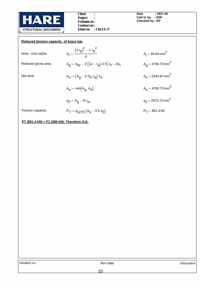
Reduced tension capacity of brace bar
Area - root radius Ar2.rb( )2 π rb
2⋅−
4:= Ar 94.64 mm2
=
Reduced gross area Ag Abr 2 w tw−( ) 0.5⋅⎡⎣ ⎤⎦⋅ tf⋅− 2Ar−:= Ag 4700.72 mm2=
Net area An Ag 2 Dh⋅ tw⋅−( ) ke⋅:= An 5244.87 mm2=
Ae min Ag An,( ):= Ae 4700.72 mm2=
a2 Ag D tw⋅−:= a2 2975.72 mm2=
Tension capacity PT py275 Ae 0.5 a2⋅−( )⋅:= PT 851.4 kN=
PT (851.4 kN) > F1 (286 kN): Therefore O.K.
Variation no: Rev date Description
33

Client : Project : Estimate no : Contract no : Sheet no :C02-C6/ 1
Date : DEC-05Calc'd by : MRChecked by : SM
15 THK GUSSET PLATE
W.P
254UC73
254UC89COL WEB
EL 6.600EL 6.575
END PLATE 160x15THKBOLTS @ 90x/CRS
(TYP)
203UC46
4070
5090
90
152UC30
NOTCH FLANGES TO SUIT
60°
118.5kN
205.
2kN 237kN
20(MIN)
240(MIN)
40
4070
4010
7040
4 NOS 60x10 THKFLANGE COVER PLATE(TYP)
2 NOS 150x10 THKWING PLATE
SLOTTED INTO GUSSET(TYP)
250(MAX)
A
A
B
B
65
30
SECTION A-A
15
SECTION B-B
60 60
909030
(MIN)(MIN)
CONNECTION NO - C02-C6
LOADS:
Brace 152UC30 F 237 kN⋅:=
LHS Beam 203UC46 Fx1 72 kN⋅:= Fv1 11kN:= Fh1 2kN:=
RHS Beam 254UC73 Fx2 127 kN⋅:= Fv2 96kN:= Fh2 25kN:=
Notes
All bolts are M20 ,Gr.8.8
All weld sizes are 6mm CFW
All main steel & fittings are S275
Variation no: Rev date Description
34

Client : Project : Estimate no : Contract no : Sheet no :C02-C6/ 2
Date : DEC-05Calc'd by : MRChecked by : SM
Sectional Properties
Column 254UC89
Dc 260.3 mm⋅:= wc 256.3 mm⋅:= Tc 17.3 mm⋅:= tc 10.3 mm⋅:= rc 12.7 mm⋅:=
LHS Beam 203UC46
Db1 203.2 mm⋅:= wb1 203.6mm:= Tb1 11 mm⋅:= tb1 7.2 mm⋅:= rb1 10.2 mm⋅:=
RHS Beam 254UC73
Db2 254.1 mm⋅:= wb2 254.6mm:= Tb2 14.2 mm⋅:= tb2 8.6 mm⋅:= rb2 12.7 mm⋅:=
Bracing152UC30
Dbr 157.6mm:= wbr 152.9 mm⋅:= Tbr 9.4mm:= tbr 6.5 mm⋅:= rbr 7.6mm:=
Material PropertiesAbr 3830mm2
:=
Design strength of S275 materialUp to & including 16 thk
py275 275N
mm2⋅:=
Design strength of S275 materialbeyond 16thk , up to and including 40mm thk
py265 265N
mm2⋅:=
Design strength of fillet weld pw 220N
mm2⋅:=
Checks for bolts for 203UC46 beam to column web (worst case)
Bolt Diameter d 20 mm⋅:=
Total no. of bolts n 8:=
Bolt pitch p 90mm:=
Bolt gauge g 90mm:=
Shear Capacity of bolt Ps 91.9kN:=
Tension Capacity of bolt Pnom 110kN:=
Vertical component of brace force Fvb1 F sin 60deg( )⋅:= Fvb1 205.2 kN=
Horizontal component of brace force Fhb1 F cos 60deg( )⋅:= Fhb1 118.5 kN=
Total vertical shear per bolt FsvFv1 Fvb1+
n:= Fsv 27.03 kN=
Hor. shear per bolt FshFh1
4:= Fsh 0.5 kN=
Variation no: Rev date Description
35

Client : Project : Estimate no : Contract no : Sheet no :C02-C6/ 3
Date : DEC-05Calc'd by : MRChecked by : SM
Resultant shear per bolt Fs Fsv2 Fsh
2+:= Fs 27.04 kN=
Tension per bolt(conservatively)
Ftmin max Fx1 Fhb1,( )( ) Fx2,⎡⎣ ⎤⎦
4:= Ft 29.63 kN=
Check for combined shear and tension RatioFsPs
FtPnom
+:= Ratio 0.56=
Ratio(0.56 ) < 1.4 : Therefore O.K.
63
108.
1092
.2
Check for weld between beam web and end plate
Tension per bolt Ft 29.63 kN=
Dispersion length on weld( for bottom bolt)
Ld 92.2 63+( )mm:= Ld 155.2 mm=
Dispersion on web Lw 92.2mm:=
Tension on web FtwFt Lw⋅
Ld:= Ftw 17.60 kN=
Tension per mm on web weld FTFtwLw
:= FT 0.191kNmm
=
Vertical shear per mm FLFv2
2 Db2 2 Tb2⋅− 2 rb2⋅−( )⋅:= FL 0.240
kNmm
=
Resultant force per mm R1FT
1.25
⎛⎜⎝
⎞
⎠
2
FL2
+:= R1 0.284kNmm
=
Size of fillet weld required sreqR1
0.7 pw⋅:=
63
108.
1092
.2
sreq 1.85mm=
Adopt 6mm CFW
Check for end plate
Weld b/w beam web & endplate s 6 mm⋅:=
Moment due to bolt force MFt2
g2
tb22
− 0.8 s⋅−⎛⎜⎝
⎞
⎠⋅:= M 0.532 kN m⋅=
Dispersion length Ld 155.2 mm= (worst case)
Thickness of plate required treqdM 6⋅
py275 Ld⋅:= treqd 8.65mm=
Adopt 15mm thk end plate
Variation no: Rev date Description
36

Client : Project : Estimate no : Contract no : Sheet no :C02-C6/ 4
Date : DEC-05Calc'd by : MRChecked by : SM
Check for bearing
Minimum thickness of connected ply tc 10.3mm=
Bearing strength pbs 460N
mm2⋅:=
Bearing Capacity (per bolt) Pbs d tc⋅ pbs⋅:= Pbs 94.76 kN=
Applied load (per bolt) FsbFv24
Fsv+⎛⎜⎝
⎞
⎠
2 Fh24
Fsh+⎛⎜⎝
⎞
⎠
2
+:= Fsb 51.48 kN=
Pbs (94.76 kN) > Fsb (51.48 kN): Therefore O.K.
Check for brace bar (152UC30)
Bolt properties in brace bar ( Each flange plate)
Bolt Diameter d2 20 mm⋅:=
Diameter of hole Dh2 22mm:=
No of bolt rows on each side nr2 2:=
No of bolt columns nc2 1:=
Total no. of bolts n2 2=
End distance et2 40mm:=
Pitch p2 70mm:=
Check for bolts in shear
FfpF4
:= Ffp 59.25 kN=Force on each flange plate
Shear capacity of bolt Fs2Ffpn2
:= Fs2 29.63 kN=
Ps (91.9 kN) > Fs2(29.62 kN): Therefore O.K.
Check for bolts in bearing
Minimum thickness of connected part Tbr 9.4 mm=
Bearing Capacity Pbs2 d2 Tbr⋅ pbs⋅ n2⋅( ):= Pbs2 172.96 kN=
Pbs2 (172.96 kN) > Ffp(59.25 kN): Therefore O.K.
Variation no: Rev date Description
37
Client : Project : Estimate no : Contract no : Sheet no :C02-C6/ 5
Date : DEC-05Calc'd by : MRChecked by : SM
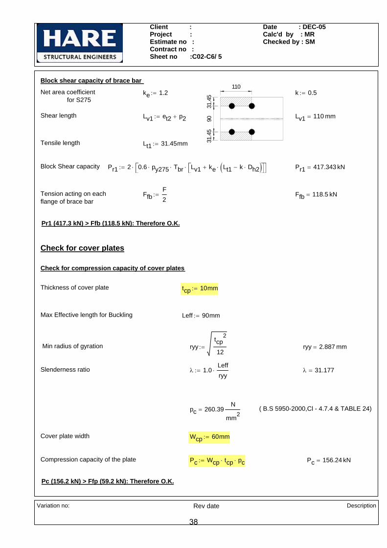
Block shear capacity of brace bar
9031
.45
31.4
5
110Net area coefficient for S275
ke 1.2:= k 0.5:=
Shear length Lv1 et2 p2+:= Lv1 110 mm=
Tensile length Lt1 31.45mm:=
Block Shear capacity Pr1 2 0.6 py275⋅ Tbr⋅ Lv1 ke Lt1 k Dh2⋅−( )⋅+⎡⎣ ⎤⎦⋅⎡⎣ ⎤⎦⋅:= Pr1 417.343 kN=
Tension acting on each flange of brace bar
FfbF2
:= Ffb 118.5 kN=
Pr1 (417.3 kN) > Ffb (118.5 kN): Therefore O.K.
Check for cover plates
Check for compression capacity of cover plates
Thickness of cover plate tcp 10mm:=
Max Effective length for Buckling Leff 90mm:=
Min radius of gyration ryytcp
2
12:= ryy 2.887 mm=
Slenderness ratio λ 1.0Leffryy
⋅:= λ 31.177=
pc 260.39N
mm2= ( B.S 5950-2000,Cl - 4.7.4 & TABLE 24)
Cover plate width Wcp 60mm:=
Compression capacity of the plate Pc Wcp tcp⋅ pc⋅:= Pc 156.24 kN=
Pc (156.2 kN) > Ffp (59.2 kN): Therefore O.K.
Variation no: Rev date Description
38

Client : Project : Estimate no : Contract no : Sheet no :C02-C6/ 6
Date : DEC-05Calc'd by : MRChecked by : SM
Check for tension capacity of cover plates
Width of cover plate Wcp 60 mm=
Tension capacity of the cover plates PTc Wcp Dh2−( ) ke⋅ tcp⋅ py275⋅:= PTc 125.4 kN=
PTc (125.4 kN) > Ffp (59.2 kN): Therefore O.K.
Check for wing plates
15
60
9030
(MIN)Eccentricity between force from bolts to C/L of gusset
ef 45mm:=
Moment induced on wing plate M Ffp ef⋅:= M 2666.25 kN mm⋅=
Thickness of wing plate twp 10mm:=
Depth of wing plate reqd. Dwp6 M⋅
1.2 twp⋅ py275⋅:= Dwp 69.626 mm=
Adopt 150 mm depth wing plate For practical reasons( )
Shear capacity of wing plate
Shear area of wing plate As 2 0.9⋅ Dwp twp⋅( )⋅:= As 1253.261 mm2=
Shear capacity of wing plate Fwp 0.6 As⋅ py275⋅:= Fwp 206.788 kN=
Force on wing plate Pwp 2 Ffp⋅:= Pwp 118.5 kN=
Fwp (206.8 kN) > Pwp (118.5 kN): Therefore O.K.
Weld between wing plate and gusset
Length available for weld Lw 2 p2 2 et2⋅+( )⋅:= Lw 300 mm=
Longitudinal force acting on weld per mm FvwFfpLw
:= Fvw 0.197kNmm
=
Size of fillet weld sFvw
0.7 pw⋅:= s 1.28mm=
Adopt 6 mm CFW
Variation no: Rev date Description
39

Client : Project : Estimate no : Contract no : Sheet no :C02-C6/ 7
Date : DEC-05Calc'd by : MRChecked by : SM
Check for Compression Capacity of Gusset Plate
Thickness of gusset plate tg 15mm:=
Dispersed width(Conservatively)
weff Dbr:= weff 157.6 mm=
Maximum effective length for buckling Leff 250mm:=
Minimum radius of gyration of gusset ryytg
2
12:= ryy 4.33mm=
Slenderness ratio λ1.5Leff
ryy:= λ 86.603=
Allowable compressive strength pc 163.92N
mm2=
Compression capacity Pc weff tg⋅ pc⋅:= Pc 387.51 kN=
Pc (387.51 kN) > F (237 kN): Therefore O.K.
Weld between gusset plate and beam flange
Horizontal component of brace force Fhb1 118.5 kN=
Length available for welding l 240 mm⋅:= Leff l 25 mm⋅−:= Leff 215 mm=
e=10
1.6Shear per mm on weld FL
Fhb12 Leff×
:= FL 0.276kNmm
=
Eccentricity of weld from w.p e 101.6 mm⋅:=
M Fhb1 e⋅:= M 12.04 kN m⋅=Moment due to eccentricity
Tension per mm on weld FTM 6⋅
2 Leff2
⋅:= FT 0.781
kNmm
=
Resultant force per mm on weld RFT
1.25
⎛⎜⎝
⎞
⎠
2
FL2
+:= R 0.683kNmm
=
Size of fillet weld required sR
pw 0.7⋅:= s 4.44mm=
Adopt 6mm CFW
Variation no: Rev date Description
40
Client : Project : Estimate no : Contract no : Sheet no :C02-C6/ 8
Date : DEC-05Calc'd by : MRChecked by : SM
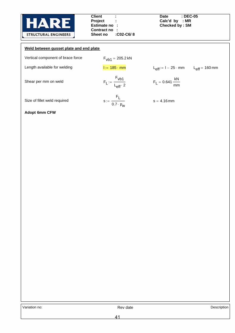
Weld between gusset plate and end plate
Vertical component of brace force Fvb1 205.2 kN=
Length available for welding l 185 mm⋅:= Leff l 25 mm⋅−:= Leff 160 mm=
Shear per mm on weld FLFvb1
Leff 2⋅:= FL 0.641
kNmm
=
Size of fillet weld required sFL
0.7 pw⋅:= s 4.16mm=
Adopt 6mm CFW
Variation no: Rev date Description
41
Client : Project : Estimate no : Contract no : Sheet no :C02-C7/ 1
Date : DEC-05Calc'd by : MSChecked by : SM
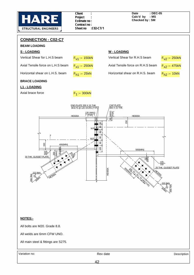
CONNECTION - C02-C7BEAM LOADING
S - LOADING W - LOADING
Vertical Shear for L.H.S beam Fv1 150kN:= Vertical Shear for R.H.S beam Fv2 250kN:=
Axial Tensile force on L.H.S beam Fx1 250kN:= Axial Tensile force on R.H.S beam Fx2 475kN:=
Horizontal shear on L.H.S. beam Fh1 25kN:= Horizontal shear on R.H.S. beam Fh2 10kN:=
BRACE LOADING
L1 - LOADING
Axial brace force F1 300kN:=
8080
8080
100
55135 (MAX)
20(M
IN)
350(MAX)
500(MIN)
150
HE40
0A
HE600AHE500A
42°
222.9kN
200.
7kN
300kN
7040
4070
70
CAP PLATE 300 X 15 THK
W.P.
10
50
(TYP) (MAX
)(T
YP)
10
HE200A
END PLATE 200 X 15 THK BOLTS @ 120 X/CRS (TYP)
25 THK. GUSSET PLATE
W.P.
42°
222.9kN
200.
7kN
300kN
70
HE200A
150 400(MIN)
200
(MAX
)
(TYP)
(TYP)
20(M
IN)
1010
20 THK. GUSSET PLATE
NOTES:-
All bolts are M20. Grade 8.8.
All welds are 6mm CFW UNO.
All main steel & fittings are S275.
Variation no: Rev date Description
42
Client : Project : Estimate no : Contract no : Sheet no :C02-C7/ 2
Date : DEC-05Calc'd by : MSChecked by : SM
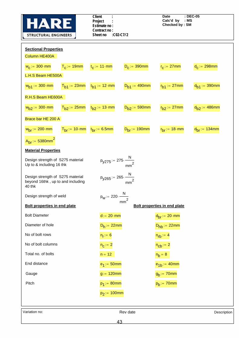
Sectional Properties
Column HE400A
wc 300 mm⋅:= Tc 19mm:= tc 11 mm⋅:= Dc 390mm:= rc 27mm:= dc 298mm:=
L.H.S Beam HE500A
wb1 300 mm⋅:= Tb1 23mm:= tb1 12 mm⋅:= Db1 490mm:= rb1 27mm:= db1 390mm:=
R.H.S Beam HE600A
wb2 300 mm⋅:= Tb2 25mm:= tb2 13 mm⋅:= Db2 590mm:= rb2 27mm:= db2 486mm:=
Brace bar HE 200 A
wbr 200 mm⋅:= Tbr 10 mm⋅:= tbr 6.5mm:= Dbr 190mm:= rbr 18 mm⋅:= dbr 134mm:=
Abr 5380mm2:=
Material Properties
Design strength of S275 materialUp to & including 16 thk
py275 275N
mm2⋅:=
Design strength of S275 materialbeyond 16thk , up to and including 40 thk
py265 265N
mm2⋅:=
Design strength of weld pw 220N
mm2⋅:=
Bolt properties in end plate Bolt properties in end plate
Bolt Diameter d 20 mm⋅:= dbr 20 mm⋅:=
Diameter of hole Dh 22mm:= Dhb 22mm:=
No of bolt rows nr 6:= nrb 4:=
No of bolt columns nc 2:= ncb 2:=
Total no. of bolts n 12= nb 8=
End distance e1 50mm:= e1b 40mm:=
Gauge g 120mm:= gb 70mm:=
Pitch p1 80mm:= pb 70mm:=
p2 100mm:=
Variation no: Rev date Description
43
Client : Project : Estimate no : Contract no : Sheet no :C02-C7/ 3
Date : DEC-05Calc'd by : MSChecked by : SM
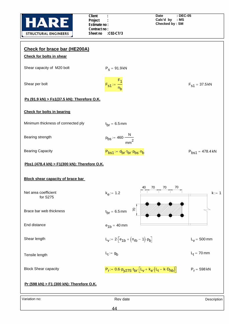
Check for brace bar (HE200A)Check for bolts in shear
Shear capacity of M20 bolt Ps 91.9kN=
Shear per bolt Fs1F1nb
:= Fs1 37.5kN=
Ps (91.9 kN) > Fs1(37.5 kN): Therefore O.K.
Check for bolts in bearing
Minimum thickness of connected ply tbr 6.5 mm=
Bearing strength pbs 460N
mm2⋅:=
Bearing Capacity Pbs1 dbr tbr⋅ pbs⋅ nb⋅:= Pbs1 478.4 kN=
Pbs1 (478.4 kN) > F1(300 kN): Therefore O.K.
Block shear capacity of brace bar
70
70 70 7040Net area coefficient for S275
ke 1.2:= k 1:=
Brace bar web thickness tbr 6.5 mm=
End distance e1b 40 mm=
Shear length Lv 2 e1b nrb 1−( ) pb⋅+⎡⎣ ⎤⎦⋅:= Lv 500 mm=
Lt gb:= Lt 70 mm=Tensile length
Block Shear capacity Pr 0.6 py275⋅ tbr⋅ Lv ke Lt k Dhb⋅−( )⋅+⎡⎣ ⎤⎦⋅:= Pr 598 kN=
Pr (598 kN) > F1 (300 kN): Therefore O.K.
Variation no: Rev date Description
44
Client : Project : Estimate no : Contract no : Sheet no :C02-C7/ 4
Date : DEC-05Calc'd by : MSChecked by : SM
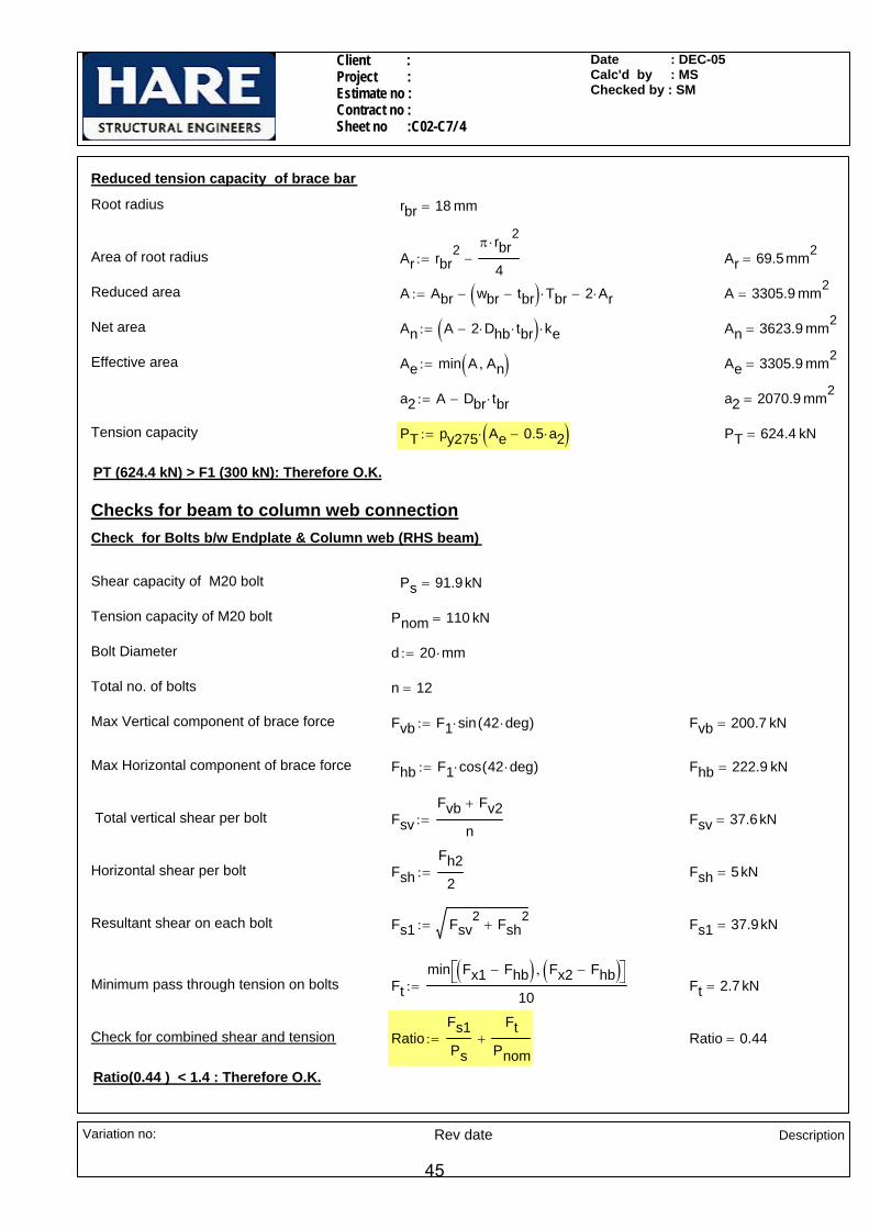
Reduced tension capacity of brace bar
Root radius rbr 18 mm=
Area of root radius Ar rbr2 π rbr
2⋅
4−:= Ar 69.5mm2
=
Reduced area A Abr wbr tbr−( ) Tbr⋅− 2 Ar⋅−:= A 3305.9 mm2=
Net area An A 2 Dhb⋅ tbr⋅−( ) ke⋅:= An 3623.9 mm2=
Effective area Ae min A An,( ):= Ae 3305.9 mm2=
a2 A Dbr tbr⋅−:= a2 2070.9 mm2=
Tension capacity PT py275 Ae 0.5 a2⋅−( )⋅:= PT 624.4 kN=
PT (624.4 kN) > F1 (300 kN): Therefore O.K.
Checks for beam to column web connectionCheck for Bolts b/w Endplate & Column web (RHS beam)
Shear capacity of M20 bolt Ps 91.9kN=
Tension capacity of M20 bolt Pnom 110 kN=
Bolt Diameter d 20 mm⋅:=
Total no. of bolts n 12=
Max Vertical component of brace force Fvb F1 sin 42 deg⋅( )⋅:= Fvb 200.7 kN=
Max Horizontal component of brace force Fhb F1 cos 42 deg⋅( )⋅:= Fhb 222.9 kN=
Total vertical shear per bolt FsvFvb Fv2+
n:= Fsv 37.6kN=
Horizontal shear per bolt FshFh2
2:= Fsh 5kN=
Resultant shear on each bolt Fs1 Fsv2 Fsh
2+:= Fs1 37.9kN=
Minimum pass through tension on bolts Ftmin Fx1 Fhb−( ) Fx2 Fhb−( ),⎡⎣ ⎤⎦
10:= Ft 2.7 kN=
Check for combined shear and tension RatioFs1Ps
FtPnom
+:= Ratio 0.44=
Ratio(0.44 ) < 1.4 : Therefore O.K.
Variation no: Rev date Description
45

Client : Project : Estimate no : Contract no : Sheet no :C02-C7/ 5
Date : DEC-05Calc'd by : MSChecked by : SM
Weld between beam web and end plate
(Worst case - RHS beam)
Depth b/w fillets of HE600A db2 486 mm=
Dispersion length for tension Ldw p1:= Ldw 80 mm=
Effective length of weld Lw 2 db2⋅:= Lw 972 mm=
Shear per mm FLFv2 Fvb+
Lw:= FL 0.464
kNmm
=
Tension per mm FTFt
Ldw:= FT 0.034
kNmm
=
Resultant force per mm RwFT
1.25
⎛⎜⎝
⎞
⎠
2
FL2
+:= Rw 0.465kNmm
=
Size of weld required sRw
pw 0.7⋅:= s 3.02mm=
Adopt 6 mm CFW.
Bending capacity of end plates 8mm:=(Worst case : LHS beam)
Dispersion length for tension Ld Ldw:= Ld 80 mm=
Moment induced on end plate MFt2
g2
tb12
− 0.8s−⎛⎜⎝
⎞
⎠⋅:= M 64.4kN mm⋅=
Thickness of end plate reqd. treqM 6⋅
py265 Ld⋅:= treq 4.27mm=
Adopt 15 thk end plate
Check for bearing capacity of end plate / column web
Vertical shear per bolt on L.H.S. beam Fsv2Fv110
:= Fsv2 15 kN=
Horizontal shear per bolt on L.H.S. beam Fsh2Fh1
2:= Fsh2 12.5kN=
Variation no: Rev date Description
46

Client : Project : Estimate no : Contract no : Sheet no :C02-C7/ 6
Date : DEC-05Calc'd by : MSChecked by : SM
Resultant shear on each bolt Fsb Fsv Fsv2+( )2 Fsh Fsh2+( )2+:= Fsb 55.4kN=
Minimum thickness of connected ply tc 11 mm=
Bearing strength pbs 460N
mm2⋅:=
Bearing Capacity of connected ply Pbs d tc⋅ pbs⋅:= Pbs 101.2 kN=
Pbs (101.2 kN) > Fsb (55.4 kN): Therefore O.K.
Check for compression capacity of gusset plate (RHS)
Thickness of gusset plate tg 25mm:=
Max Effective length for Buckling Leff 350mm:=
Min radius of gyration ryytg
2
12:= ryy 7.2 mm=
Slenderness ratio λ 1.5Leffryy
⋅:= λ 72.7=
pc 191.1N
mm2= ( B.S 5950-2000,Cl - 4.7.4 & TABLE 24)
Max available dispersed length within gusset wd Dbr:= wd 190 mm=
conservatively( )
Compressive strength of the plate Pc wd tg⋅ pc⋅:= Pc 907.7 kN=
70
60
225.4Pc (907.7 kN) > F1 (300 kN): Therefore O.K.
Check for gusset plate against minor axis bending (RHS)
Minimum width considered forminor axis moment
w 225.4 70+ 60+( )mm:=
w 355.4 mm=
Variation no: Rev date Description
47

Client : Project : Estimate no : Contract no : Sheet no :C02-C7/ 7
Date : DEC-05Calc'd by : MSChecked by : SM
Moment due to eccentricity Mtg2
tbr2
+⎛⎜⎝
⎞
⎠F1⋅:= M 4.7 kN m⋅=
Moment capacity of gusset plate
Mcapw tg
2⋅
61.2⋅ py265⋅:= Mcap 11.8kN m⋅=
Check for combined axial and moment RF1Pc
MMcap
+:= R 0.73= < 1
Adopt 25 thk gusset plate
Weld between gusset plate and beam bottom flange (RHS)
Max Horizontal component of brace force Fhb F1 cos 42deg( )⋅:= Fhb 222.9 kN=
Length available for welding L 500 mm⋅:=
Shear force per mm on weld FLFhb2 L×
:= FL 0.223kNmm
=
C.G.
W.P.
ev=4
40
eh=175
Max vertical component of brace force Fvb 200.7 kN=
Eccentricity b/w W.P & C.G. of weld ev 440mm:=
Eccentricity b/w Line of action & C.G. of weld eh 175mm:=
Moment due to vertical component Mv Fvb eh⋅:= Mv 35.1kN m⋅=
Moment due to horizontal component Mh Fhb ev⋅:= Mh 98.1kN m⋅=
Total moment due to components M Mh Mv+:= M 133.2 kN m⋅=Conservatively( )
FTM 6⋅
2 L2⋅
Fvb2 L⋅
+:= FT 1.799kNmm
=Tensile force on weld
Resultant force on weld RFT
1.25
⎛⎜⎝
⎞
⎠
2
FL2
+:= R 1.457kNmm
=
Variation no: Rev date Description
48

Client : Project : Estimate no : Contract no : Sheet no :C02-C7/ 8
Date : DEC-05Calc'd by : MSChecked by : SM
Size of weld required sR
pw 0.7⋅:= s 9.46mm=
tb1
dn=(
Db1-
dcn-
Tb1)
Tb1
Wb1
Adopt 10mm CFW
Check for Shear & Bending interaction at the Notch for L.H.S. beam
Depth of notch dcn 55mm:=
Length of notch c 135mm:=
Thickness of end plate tp 15mm:=
Depth of web of notched section Dn1 Db1 dcn− Tb1−:= Dn1 412 mm=
C.G. of notched section from top end of notch
yt1
tb1 Dn1⋅Dn1
2⋅
⎛⎜⎝
⎞
⎠wb1 Tb1⋅ Dn1
Tb12
+⎛⎜⎝
⎞
⎠⋅
⎡⎢⎣
⎤⎥⎦
+
tb1 Dn1⋅ wb1 Tb1⋅+:= yt1 332.7 mm=
Ymax1 max Db1 dcn− yt1− yt1,( ):= Ymax1 332.7 mm=
Taking second moment of area about N.A of notched beam
Ixx1tb1 Dn1
3⋅
12tb1 Dn1⋅ yt1
Dn12
−⎛⎜⎝
⎞
⎠
2
⋅
⎡⎢⎢⎣
⎤⎥⎥⎦
+
⎡⎢⎢⎣
⎤⎥⎥⎦
wb1 Tb13
⋅
12
⎛⎜⎜⎝
⎞
⎠wb1 Tb1⋅ Dn1
Tb12
+ yt1−⎛⎜⎝
⎞
⎠
2
⋅+
⎡⎢⎢⎣
⎤⎥⎥⎦
+:=
Ixx1 206492206.04 mm4=
Iyy1Tb1 wb1
3⋅
12
Dn1 tb13
⋅
12+:= Iyy1 51809328 mm4
=
Section modulus of reduced section about xx axis
Zxx1Ixx1
Ymax1:= Zxx1 620637.7 mm3
=
Major axis bending capacity Mcx1 Zxx1 py265⋅:= Mcx1 164.5 kN m⋅=
Moment due to vertical shear Mx1 Fv1 c tp+( )⋅:= Mx1 22.5kN m⋅=
Section modulus of reduced section about yy axis
Zyy1Iyy1wb1
2
:= Zyy1 345395.5 mm3=
Minor axis bending capacity Mcy1 Zyy1 py265⋅:= Mcy1 91.5kN m⋅=
Variation no: Rev date Description
49

Client : Project : Estimate no : Contract no : Sheet no :C02-C7/ 9
Date : DEC-05Calc'd by : MSChecked by : SM
Moment due to horizontal shear My1 Fh1 c tp+( )⋅:= My1 3.8 kN m⋅=
Axial capacity of notched beam Pt1 Dn1 tb1⋅ wb1 Tb1⋅+( ) py265⋅:= Pt1 3138.7 kN=
Interaction ratio RMx1Mcx1
My1Mcy1
+Fx1Pt1
+:= R 0.26=
1.0 > R (0.26 ): Therefore O.K.
Check for Shear & Bending interaction at the Notch for R.H.S. beam
Depth of notched section Dn2 Db2 dcn− Tb2−:= Dn2 510 mm=
C.G. of notched section from top
yt2
tb2 Dn2⋅Dn2
2⋅
⎛⎜⎝
⎞
⎠wb2 Tb2⋅ Dn2
Tb22
+⎛⎜⎝
⎞
⎠⋅
⎡⎢⎣
⎤⎥⎦
+
tb2 Dn2⋅ wb2 Tb2⋅+:= yt2 397 mm=
Ymax2 max Db2 dcn− yt2− yt2,( ):= Ymax2 397 mm=
Taking second moment of area about top of notched beam
Ixx2tb2 Dn2
3⋅
12tb2 Dn2⋅ yt2
Dn22
−⎛⎜⎝
⎞
⎠
2
⋅
⎡⎢⎢⎣
⎤⎥⎥⎦
+
⎡⎢⎢⎣
⎤⎥⎥⎦
wb2 Tb23
⋅
12
⎛⎜⎜⎝
⎞
⎠wb2 Tb2⋅ Dn2
Tb22
+ yt2−⎛⎜⎝
⎞
⎠
2
⋅+
⎡⎢⎢⎣
⎤⎥⎥⎦
+:=
Ixx2 395910066.88 mm4=
Iyy2Tb2 wb2
3⋅
12
Dn2 tb23
⋅
12+:= Iyy2 56343372.5 mm4
=
Section modulus of reduced section about xx axis
Zxx2Ixx2
Ymax2:= Zxx2 997291.9 mm3
=
Major axis bending capacity Mcx2 Zxx2 py265⋅:= Mcx2 264.3 kN m⋅=
Moment due to vertical shear Mx2 Fv2 c tp+( )⋅:= Mx2 37.5kN m⋅=
Section modulus of reduced section about yy axis
Zyy2Iyy2wb2
2
:= Zyy2 375622.5 mm3=
Minor axis bending capacity Mcy2 Zyy2 py265⋅:= Mcy2 99.5kN m⋅=
Moment due to horizontal shear My2 Fh2 c tp+( )⋅:= My2 1.5 kN m⋅=
Variation no: Rev date Description
50

Client : Project : Estimate no : Contract no : Sheet no :C02-C7/ 10
Date : DEC-05Calc'd by : MSChecked by : SM
Axial capacity of notched beam Pt2 Dn2 tb2⋅ wb2 Tb2⋅+( ) py265⋅:= Pt2 3744.5 kN=
Interaction ratio RMx2Mcx2
My2Mcy2
+Fx2Pt2
+:= R 0.28=
1.0 > R (0.28 ): Therefore O.K.
200
(MAX
)
170.18 170.18
Check for compression capacity of gusset plate (LHS)
Thickness of gusset plate tg 20mm:=
Max Effective length for Buckling Leff 200mm:=
Min radius of gyration ryytg
2
12:= ryy 5.8 mm=
Slenderness ratio λ 1.5Leffryy
⋅:= λ 52=
pc 226N
mm2= ( B.S 5950-2000,Cl - 4.7.4 & TABLE 24)
Max available dispersed width within gusset(conservatively)
wd 2 170.18mm( )⋅:= wd 340.4 mm=
Compressive strength of the plate Pc wd tg⋅ pc⋅:=
Pc 1538.1 kN=
Pc1 (1538.11 kN) > Fvb (200.74 kN): Therefore O.K.
Check for gusset plate for combined axial & moment (LHS)
200
(MAX
)
400(MIN)
243.19
130
Minimum width considered forminor axis moment
w 243.19mm 130mm+( ):=
(Conservatively)w 373.2 mm=
Minor axis moment due to vertical component eccentricity
Mytg2
tbr2
+⎛⎜⎝
⎞
⎠Fvb⋅:=
My 2.7 kN m⋅=
Minor axis moment capacity of gusset plate
Mcapyw tg
2⋅
61.2⋅ py265⋅:= Mcapy 7.9 kN m⋅=
Variation no: Rev date Description
51
Client : Project : Estimate no : Contract no : Sheet no :C02-C7/ 11
Date : DEC-05Calc'd by : MSChecked by : SM
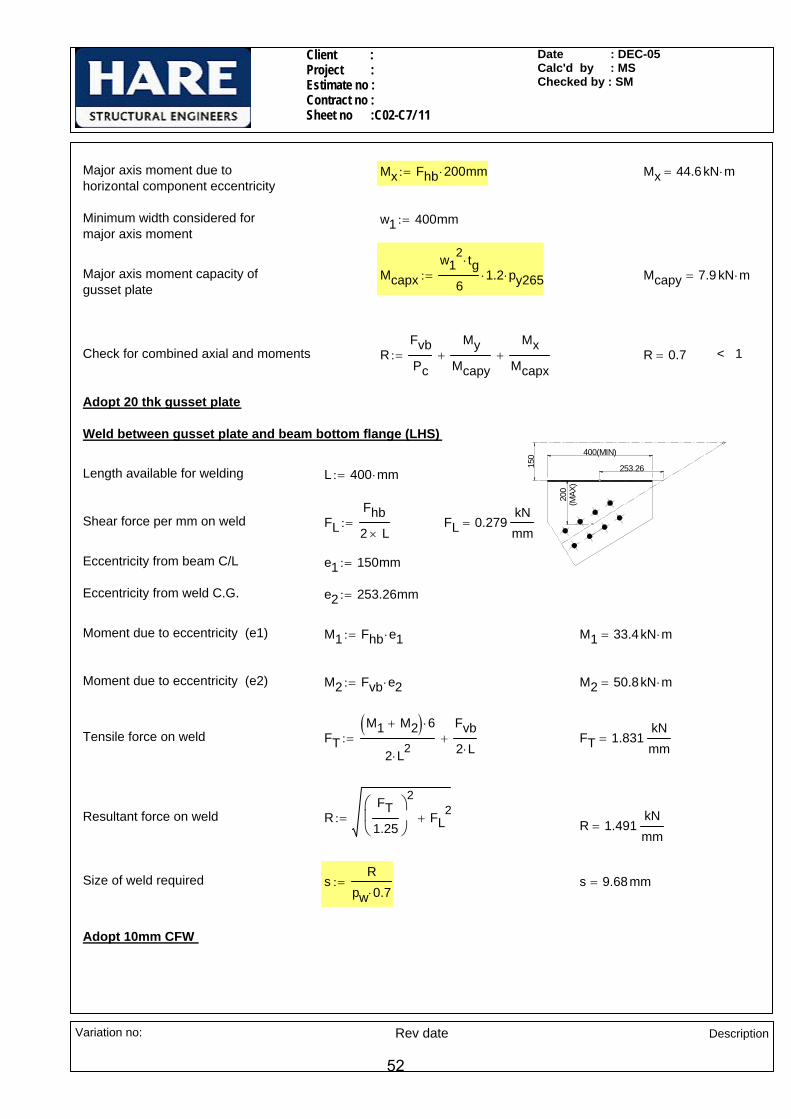
Major axis moment due to horizontal component eccentricity
Mx Fhb 200⋅ mm:= Mx 44.6kN m⋅=
Minimum width considered formajor axis moment
w1 400mm:=
Major axis moment capacity of gusset plate
Mcapxw1
2 tg⋅
61.2⋅ py265⋅:= Mcapy 7.9 kN m⋅=
Check for combined axial and moments RFvbPc
MyMcapy
+Mx
Mcapx+:= R 0.7= < 1
Adopt 20 thk gusset plate
Weld between gusset plate and beam bottom flange (LHS)
200
(MAX
)
400(MIN)
253.26150
Length available for welding L 400 mm⋅:=
Shear force per mm on weld FLFhb2 L×
:= FL 0.279kNmm
=
Eccentricity from beam C/L e1 150mm:=
Eccentricity from weld C.G. e2 253.26mm:=
Moment due to eccentricity (e1) M1 Fhb e1⋅:= M1 33.4kN m⋅=
Moment due to eccentricity (e2) M2 Fvb e2⋅:= M2 50.8kN m⋅=
Tensile force on weld FTM1 M2+( ) 6⋅
2 L2⋅
Fvb2 L⋅
+:= FT 1.831kNmm
=
Resultant force on weld RFT
1.25
⎛⎜⎝
⎞
⎠
2
FL2
+:= R 1.491kNmm
=
Size of weld required sR
pw 0.7⋅:= s 9.68mm=
Adopt 10mm CFW
Variation no: Rev date Description
52

Client : Project : Estimate no: Contract no: Sheet no : C03-C1/ 1
Date : DEC - 05Calc'd by : JLChecked by : SM
CONNECTION NO - C03-C1
Load on UC 152x152x30 Fy 10kN:= Fx 50kN:= Fh 5kN:=
Load on UB 203x133x25 Fy1 15 kN⋅:= Fx1 15 kN⋅:=
Load on Plan brace F 15 kN⋅:=
152x152x30UC
AA
SECTION A-A
(TYP
)
254x
254x
73UC
72(T
YP)
40
5070
254x254x73UC
40280(MAX)
33.69
°
40
50 7012.48 kN
15 kN
8.32 k
N
RSA 90x90x8
15 THK CONNECTIONPLATE (TYP)
B
110
40(M
IN)
152x
152x
30UC
6060
2870
28
203x133x25UB
130x15 THK END PLATE (TYP)
200x15 THK END PLATE
40 (TYP)50
203x133x25UBB
110
130x15 THK END PLATE (TYP)
200x15 THK END PLATE
NOTES:-
All bolts are M20, Grade 8.8
All welds are 6mm CFW
All main steel & fittings are S275
Variation no : Rev date Description
53

Client : Project : Estimate no: Contract no: Sheet no : C03-C1/ 2
Date : DEC - 05Calc'd by : JLChecked by : SM
Sectional propertiesColumn UC254x254x73
Dc 254.1mm:= wc 254.6mm:= Tc 14.2mm:= tc 8.6mm:= rc 12.7mm:= dc 200.3mm:= Ac 9310mm2:=
Beam UB203x133x25
Db1 203.2mm:= wb1 133.2mm:= Tb1 7.8mm:= tb1 5.7mm:= rb1 7.6mm:= db1 172.4mm:= Ab1 3200mm2:=
Beam UC152x152x30
Db2 157.6mm:= wb2 152.9mm:= Tb2 9.4mm:= tb2 6.5mm:= rb2 7.6mm:= db2 123.6mm:= Ab2 3830mm2:=
Bracing
RSA90x90x8 Dbr 90mm:= wbr 90 mm⋅:= tbr 8mm:= Abr 1390mm2:=
MATERIAL PROPERTIES
Design strength of S275 material - up to & including 16thk.
py275 275N
mm2⋅:= Design strength of fillet -
weld for S275 material pw 220
N
mm2⋅:=
Design strength of S275 material - beyond 16thk. and including 40thk.
py265 265N
mm2⋅:=
Bearing strength of S275 - material
pbs275 460N
mm2:=
Checks for brace memberCheck for bolts between brace and gusset
Bolt Diameter d 20 mm⋅:=
Diameter of hole Dh 22mm:=
No .of bolt rows nr 2:=
No of bolt columns nc 1:=
Total no. of bolts n 2=
Shear capacity of M20 bolt Ps 91.9kN=
Shear load on each Bolt FsFn
:= Fs 7.5 kN=
Ps (91.9 kN) > Fs (7.5 kN): Therefore O.K.
Check for bearing capacity of brace bar / gusset plate
Bearing Capacity of brace bar per bolt hole Pbs d tbr⋅ pbs275⋅:= Pbs 73.6kN=
Pbs (73.6 kN) > Fs (7.5 kN): Therefore O.K.
Variation no : Rev date Description
54

Client : Project : Estimate no: Contract no: Sheet no : C03-C1/ 3
Date : DEC - 05Calc'd by : JLChecked by : SM
Block shear capacity of brace bar
Net area coefficient for grade S275 ke275 1.2:=
Pitch p 70mm:=
End distance et 40mm:=
Shear length Lv et nr 1−( ) p⋅+:= Lv 110 mm=
Tensile length Lt 40mm:=
Block Shear capacity Pr 0.6 py275⋅ tbr⋅ Lv ke275 Lt 0.5 Dh⋅−( )⋅+⎡⎣ ⎤⎦⋅:= Pr 191.1 kN=
Pr (191.1 kN) > F (15 kN): Therefore O.K.
Tension capacity of brace bar
Net area An Abr 1 Dh⋅ tbr⋅−( ) ke275⋅:= An 1456.8 mm2=
Effective area As min An Abr,( ):= As 1390 mm2=
Tension capacity PT py275 As( )⋅:= PT 382.3 kN=
PT (382.2 kN) > F (15 kN): Therefore O.K.
Check for UB 203x133x25
Tensile capacity of M20 bolt Pnom 110kN:=
Total tension per bolt FtFx16
:= Ft 2.5 kN= < 110kN
Vertical Shear per bolt FsFy16
:= Fs 2.5 kN= < 91.9kN
Combined Ratio RatioFsPs
FtPnom
+:= Ratio 0.05=
Ratio (0.05 ) < 1.4 , Therefore O.K.
6054
.60
56.15Check for weld between beam web and end plate
Min Dispersion length on weld Ld2 110.75 mm⋅:=
Dispersion on web Lw 54.60 mm⋅:=
Tension on web(conservatively) FtwFt Lw⋅
Ld2:= Ftw 1.233 kN=
Variation no : Rev date Description
55
Client : Project : Estimate no: Contract no: Sheet no : C03-C1/ 4
Date : DEC - 05Calc'd by : JLChecked by : SM
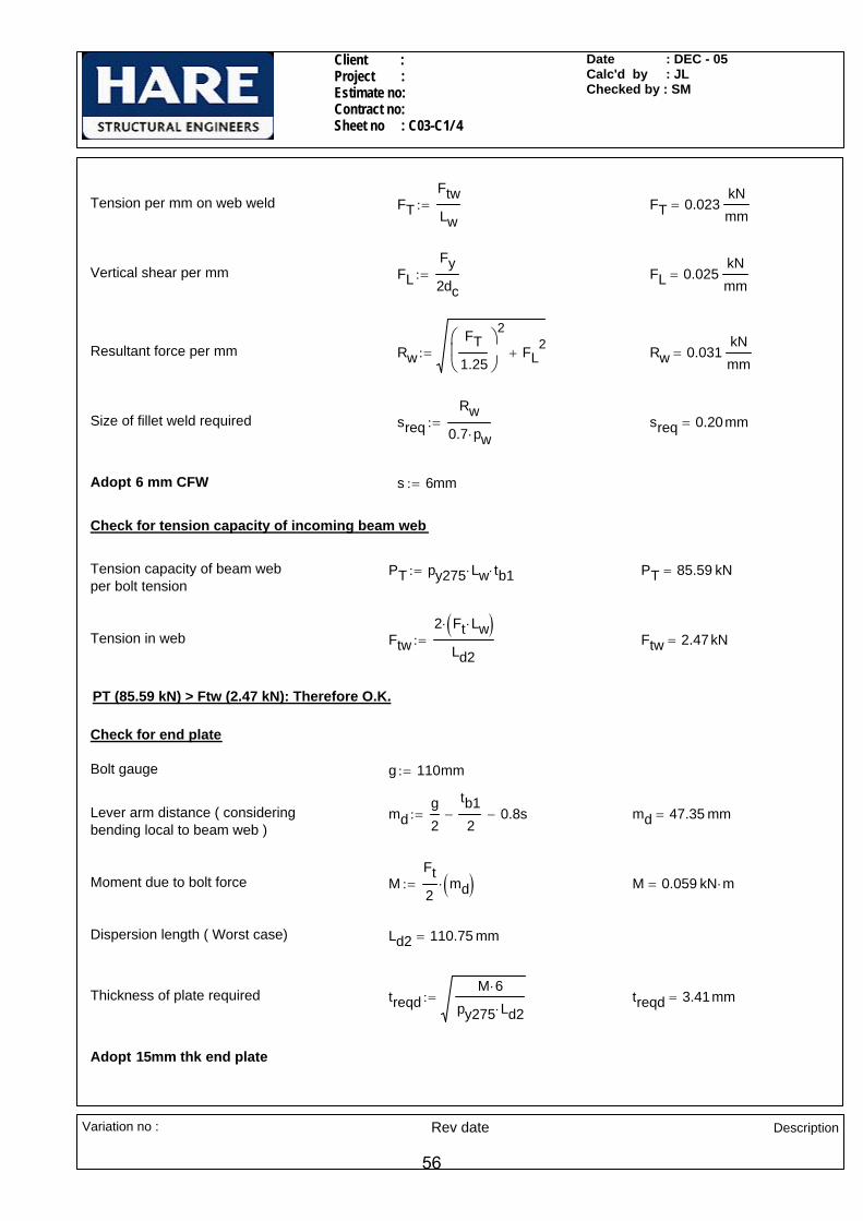
Tension per mm on web weld FTFtwLw
:= FT 0.023kNmm
=
Vertical shear per mm FLFy2dc
:= FL 0.025kNmm
=
Resultant force per mm RwFT
1.25
⎛⎜⎝
⎞
⎠
2
FL2
+:= Rw 0.031kNmm
=
Size of fillet weld required sreqRw
0.7 pw⋅:= sreq 0.20mm=
Adopt 6 mm CFW s 6mm:=
Check for tension capacity of incoming beam web
Tension capacity of beam web per bolt tension
PT py275 Lw⋅ tb1⋅:= PT 85.59 kN=
Tension in web Ftw2 Ft Lw⋅( )⋅
Ld2:= Ftw 2.47kN=
PT (85.59 kN) > Ftw (2.47 kN): Therefore O.K.
Check for end plate
Bolt gauge g 110mm:=
Lever arm distance ( considering bending local to beam web )
mdg2
tb12
− 0.8s−:= md 47.35 mm=
Moment due to bolt force MFt2
md( )⋅:= M 0.059 kN m⋅=
Dispersion length ( Worst case) Ld2 110.75 mm=
Thickness of plate required treqdM 6⋅
py275 Ld2⋅:= treqd 3.41mm=
Adopt 15mm thk end plate
Variation no : Rev date Description
56

Client : Project : Estimate no: Contract no: Sheet no : C03-C1/ 5
Date : DEC - 05Calc'd by : JLChecked by : SM
Check for bolts & end plate for UC 152x152x30
Dia of bolt d 20mm:=
No of bolt rows nr 4:=
No of bolt columns nc 2:=
Total no of bolts n 8=
Bolt gauge g 110mm:=
Shear capacity of M20 bolt Ps 91.9kN:=
Tension capacity of M20 bolt Pnom 110kN:=
Tension per bolt Ft1Fx4
:= Ft1 12.5kN= < 110 kN
Total horizontal shear per bolt FhsFh4
:= Fhs 1.25kN=
Total vertical shear per bolt FsvFyn
:= Fsv 1.25kN= < 91.9kN
Resultant shear per Bolt Fs Fhs2 Fsv
2+:= Fs 1.77kN=
Combined shear and tension RatioFsPs
Ft1Pnom
+⎛⎜⎜⎝
⎞
⎠:= Ratio 0.13=
Ratio ( 0.13 ) < 1.4 : Therefore O.K.
11065.60
55.60
Weld between beam web and end plate
Depth b/w fillet db 123.6 mm⋅:=
Dispersion length Lt 121.20 mm⋅:=
Dispersion along web Lw 55.60mm:=
Tensile force on web Ftw Ft1LwLt
⋅:= Ftw 5.73kN=
Tension per mm FTFtwLw
:= FT 0.103kNmm
=
Variation no : Rev date Description
57
Client : Project : Estimate no: Contract no: Sheet no : C03-C1/ 6
Date : DEC - 05Calc'd by : JLChecked by : SM
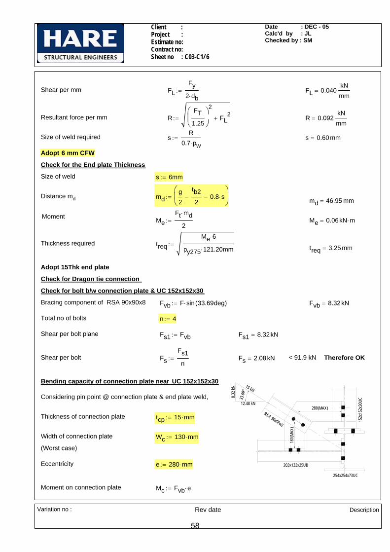
Shear per mm FLFy
2 db⋅:= FL 0.040
kNmm
=
Resultant force per mm RFT
1.25
⎛⎜⎝
⎞
⎠
2
FL2
+:= R 0.092kNmm
=
Size of weld required sR
0.7 pw⋅:= s 0.60mm=
Adopt 6 mm CFW
Check for the End plate Thickness
Size of weld s 6mm:=
Distance md mdg2
tb22
− 0.8 s⋅−⎛⎜⎝
⎞
⎠:= md 46.95 mm=
Moment MeFt md⋅
2:= Me 0.06kN m⋅=
Thickness required treqMe 6⋅
py275 121.20⋅ mm:= treq 3.25mm=
Adopt 15Thk end plate
Check for Dragon tie connection
Check for bolt b/w connection plate & UC 152x152x30
Bracing component of RSA 90x90x8 Fvb F sin 33.69deg( )⋅:= Fvb 8.32kN=
Total no of bolts n 4:=
Shear per bolt plane Fs1 Fvb:= Fs1 8.32kN=
Shear per bolt FsFs1n
:= Fs 2.08kN= < 91.9 kN Therefore OK
203x133x25UB
254x254x73UC
RSA 90x90x8
280(MAX)
152x
152x
30UC
180(
MAX)
12.48 kN
15 kN
8.32 k
N
33.69
°
Bending capacity of connection plate near UC 152x152x30
Considering pin point @ connection plate & end plate weld,
Thickness of connection plate tcp 15 mm⋅:=
Width of connection plate Wc 130 mm⋅:=
(Worst case)
Eccentricity e 280 mm⋅:=
Moment on connection plate Mc Fvb e⋅:=
Variation no : Rev date Description
58
Client : Project : Estimate no: Contract no: Sheet no : C03-C1/ 7
Date : DEC - 05Calc'd by : JLChecked by : SM
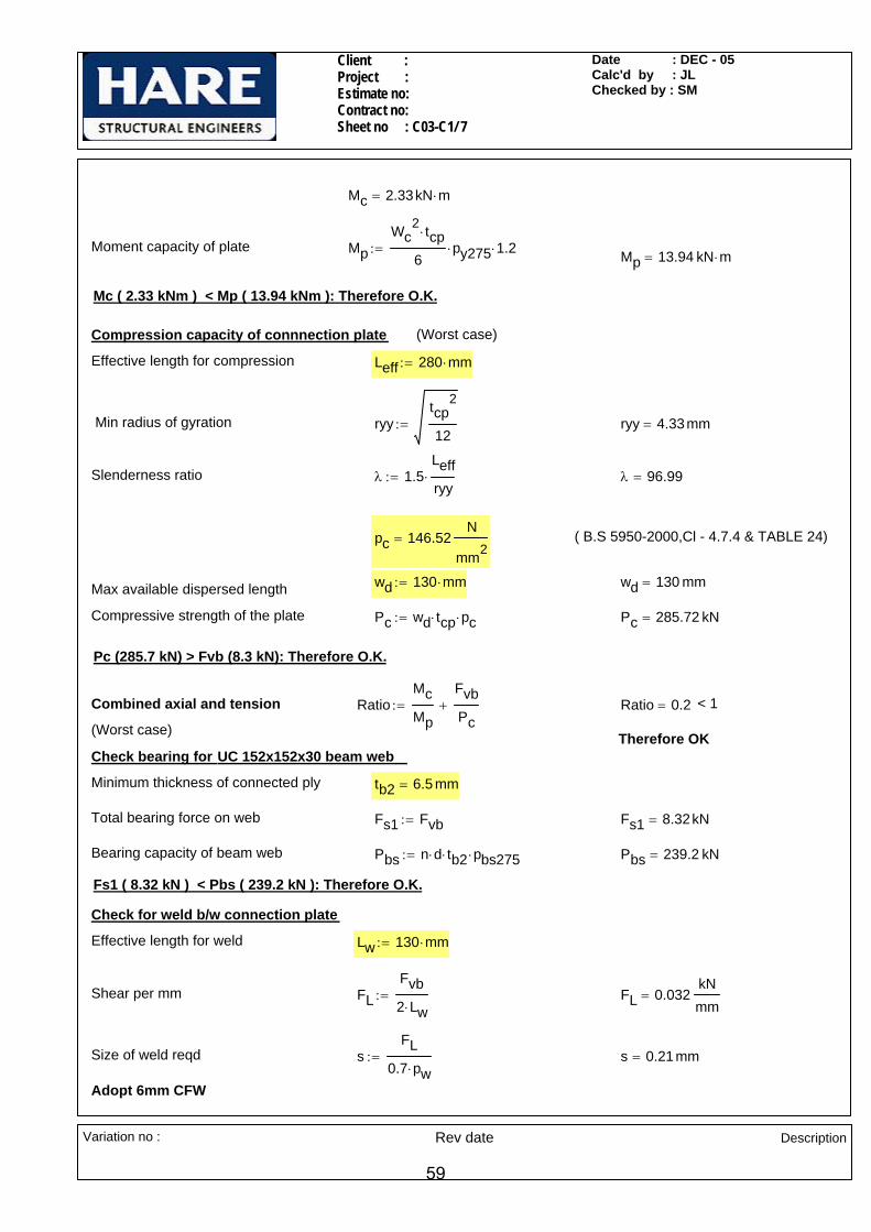
Mc 2.33kN m⋅=
Moment capacity of plate MpWc
2 tcp⋅
6py275⋅ 1.2⋅:= Mp 13.94 kN m⋅=
Mc ( 2.33 kNm ) < Mp ( 13.94 kNm ): Therefore O.K.
Compression capacity of connnection plate (Worst case)
Effective length for compression Leff 280 mm⋅:=
Min radius of gyration ryytcp
2
12:= ryy 4.33mm=
Slenderness ratio λ 1.5Leffryy
⋅:= λ 96.99=
pc 146.52N
mm2= ( B.S 5950-2000,Cl - 4.7.4 & TABLE 24)
wd 130 mm⋅:= wd 130 mm=Max available dispersed length
Compressive strength of the plate Pc wd tcp⋅ pc⋅:= Pc 285.72 kN=
Pc (285.7 kN) > Fvb (8.3 kN): Therefore O.K.
Combined axial and tension RatioMcMp
FvbPc
+:= Ratio 0.2= < 1
(Worst case) Therefore OK Check bearing for UC 152x152x30 beam web
Minimum thickness of connected ply tb2 6.5 mm=
Total bearing force on web Fs1 Fvb:= Fs1 8.32kN=
Bearing capacity of beam web Pbs n d⋅ tb2⋅ pbs275⋅:= Pbs 239.2 kN=
Fs1 ( 8.32 kN ) < Pbs ( 239.2 kN ): Therefore O.K.
Check for weld b/w connection plate
Effective length for weld Lw 130 mm⋅:=
Shear per mm FLFvb2 Lw⋅
:= FL 0.032kNmm
=
Size of weld reqd sFL
0.7 pw⋅:= s 0.21mm=
Adopt 6mm CFW
Variation no : Rev date Description
59

Client : Project : Estimate no: Contract no: Sheet no : C03-C1/ 8
Date : DEC - 05Calc'd by : JLChecked by : SM
Check for bolt b/w connection plate & UB 203x133x25
Bracing component of RSA 90x90x8 Fhb F cos 33.69deg( )⋅:= Fhb 12.48 kN=
Total no of bolts n 4:=
Shear per bolt plane Fs2 Fhb:= Fs2 12.48 kN=
Shear per bolt Fs3Fs2n
:= Fs3 3.12kN= < 91.9 kN
Bending capacity of connection plate near UB 203x133x25 Therefore OK
203x133x25UB
254x254x73UC
RSA 90x90x8
280(MAX)
152x
152x
30UC
180(
MAX)
12.48 kN
15 kN
8.32 k
N
33.69
°Considering pin point @ connection plate & end plate weld,
Eccentricity e1 180 mm⋅:=
Moment on connection plate Mc1 Fhb e1⋅:=
Mc1 2.25kN m⋅=
Mc1 ( 2.25 kNm ) < Mp ( 13.94 kNm ): Therefore O.K.
Compression capacity of connnection plate
Effective length for compression Leff1 e1:=
Slenderness ratio λ1 1.5Leffryy
⋅:= λ1 96.99=
pc1 146.52N
mm2= ( B.S 5950-2000,Cl - 4.7.4 & TABLE 24)
Compressive strength of the plate Pc1 wd tcp⋅ pc⋅:= Pc1 285.72 kN=
Pc (285.7 kN) > Fvb (8.3 kN): Therefore O.K.
Combined axial and tension RatioMc1Mp
FhbPc1
+:= Ratio 0.2= < 1
(Worst case) Therefore OK
Check bearing for UB 203x133x25 beam web
Minimum thickness of connected ply tb1 5.7 mm=
Total bearing force on web Fs1 Fhb:= Fs1 12.48 kN=
Bearing capacity of beam web Pbs n d⋅ tb1⋅ pbs275⋅:= Pbs 209.76 kN=
Fs1 ( 12.48 kN ) < Pbs ( 209.76 kN ): Therefore O.K.
Variation no : Rev date Description
60

Client : Project : Estimate no: Contract no: Sheet no : C03-C1/ 9
Date : DEC - 05Calc'd by : JLChecked by : SM
Check for weld b/w connection plate
Shear per mm FL1Fhb2 Lw⋅
:= FL1 0.048kNmm
=
Size of weld reqd s1FL1
0.7 pw⋅:= s1 0.31mm=
Adopt 6mm CFW
Variation no : Rev date Description
61

Client : Project : Estimate no : Contract no : Sheet no : C03-C2 / 1
Date : DEC-05Calc'd by : MSChecked by : SM
CONNECTION - C03-C2
Vertical shear in UC 203X203X46 Fv1 105kN:= Vertical shear in UC 152X152X30 Fv2 2kN:=
Horizontal shear in UC 203X203X46 Fh1 37kN:= Axial force in UC 152X152X30 Fx2 71kN:=
Axial force in UC 203X203X46 Fx1 119kN:= Axial force in brace member F 89kN:=
(TYP)
62kN44
64kN
89kN
°
90
115 70
°89kN
64kN
44 62kN
°
89kN
64kN
4462kN
90(TY
P)GUSSET 15 THK.
350(MAX)(TYP)
200(MIN)
UC 152X152X30 UC 203X203X46
UC 305X305X118
4040(TYP)
20(M
IN)
(TYP
)
A A
SECTION A-A
GUSSET 15 THK.
160(MAX)(TYP) 35
(MAX
)(T
YP)
BOTTOM FLANGE TRIMMED TO MISS BOLTS
END PLATE 250 X 15 THK BOLTS @ 120 X/CRS
W.P.
UC 152X152X30(TYP)
100
UC 203X203X46
UC 152X152X30
20(M
IN)
(TYP)
BRACE BAR NOT SHOWN FOR CLARITY
NOTES:-
All bolts are M20. Grade 8.8.
All welds are 6 CFW.
All main steel & fittings are S275.
Variation no: Rev date Description
62

Client : Project : Estimate no : Contract no : Sheet no : C03-C2 / 2
Date : DEC-05Calc'd by : MSChecked by : SM
Sectional Properties
Brace bar UC 152 X 152 X 30
Dbr 157.6mm:= Wbr 152.9 mm⋅:= tbr 6.5mm:= Tbr 9.4 mm⋅:= rbr 7.6 mm⋅:= Abr 3830mm2:= dbr 123.6mm:=
L.H.S. Beam UC 152 X 152 X 30
Db1 157.6mm:= Wb1 152.9 mm⋅:= tb1 6.5mm:= Tb1 9.4 mm⋅:= rb1 7.6 mm⋅:= Ab1 3830mm2:= db1 123.6mm:=
R.H.S. Beam UC 203 X 203 X 46
Db2 203.2mm:= Wb2 203.6 mm⋅:= tb2 7.2mm:= Tb2 11 mm⋅:= rb2 10.2 mm⋅:= Ab2 5870mm2:= db2 160.8mm:=
Material Properties
Design strength of S275 materialUp to and including 16 thk
py275 275N
mm2⋅:=
Design strength of S275 materialbeyond 16thk, Up to and including 40mm thk
py265 265N
mm2⋅:=
Bearing Strength of S275 material pbs 460
N
mm2:=
Design strength of weld pw 220N
mm2⋅:=
Bolt properties in brace bar Bolt properties in end plate
Bolt Diameter d 20 mm⋅:= d 20 mm⋅:=
Diameter of bolt hole Dh 22mm:= Dh 22mm:=
No of bolt rows nrb 1:= nr 2:=
No of bolt columns ncb 2:= nc 2:=
Total no. of bolts nb 2= n 4=
End distance etb 40mm:= et 35mm:=
Gauge gb 90mm:= g 120mm:=
Shear capacity of M20 bolt Ps 91.9kN:= Pitch p 90mm:=
Tension capacity of M20 bolt Pnom 110kN:=
Variation no: Rev date Description
63

Client : Project : Estimate no : Contract no : Sheet no : C03-C2 / 3
Date : DEC-05Calc'd by : MSChecked by : SM
Check for brace bar (UC 152X152X30)
Check for bolts between brace and gusset
Shear force on each bolt FsFnb
:= Fs 44.5kN=
Ps (91.9 kN) > Fs (44.5 kN): Therefore O.K.
Check for bolts in bearing
Minimum thickness of connected part Tbr 9.4 mm=
Bearing Capacity Pbs d Tbr⋅ pbs⋅ nb⋅:= Pbs 172.96 kN=
Pbs (172.96 kN) > F (89 kN): Therefore O.K.
Block shear capacity of brace bar
40
31.45
Net area coefficient for S275
ke 1.2:= k 0.5:=
Thickness of flange of brace bar Tbr 9.4 mm=
Shear length Lv etb:= Lv 40 mm=
LtWbr gb−
2:= Lt 31.45 mm=Tensile length
Block Shear capacityPr 2 0.6 py275⋅ Tbr⋅ Lv ke Lt k Dh⋅−( )⋅+⎡⎣ ⎤⎦⋅⎡⎣ ⎤⎦⋅:= Pr 200.20 kN=
Pr (200.2 kN) > F (89 kN): Therefore O.K.
Check for gussetCheck for compression capacity of gusset plate
Thickness of gusset plate tg 15mm:=
Max Effective length for Buckling Leff 350mm:=
Min radius of gyration ryytg
2
12:= ryy 4.33mm=
Slenderness ratio λ 1.5Leffryy
⋅:= λ 121.24=
pc 106.13N
mm2= ( B.S 5950-2000,Cl - 4.7.4 & TABLE 24)
Variation no: Rev date Description
64

Client : Project : Estimate no : Contract no : Sheet no : C03-C2 / 4
Date : DEC-05Calc'd by : MSChecked by : SM
Max available dispersed length within gusset wd gb:= wd 90 mm=
Compression capacity of the plate Pc wd tg⋅ pc⋅:= Pc 143.27 kN=
Pc (143.27 kN) > F (89 kN): Therefore O.K.
Check for weld between end plate and gusset
(Worst case)
Length of the weld b/w end plate and gusset Lw
250mm tb2−
2
⎛⎜⎝
⎞
⎠25mm−:= Lw 96.4mm=
Shear force per mm on weldFLe
F sin 44deg( )⋅
2 Lw⋅:= FLe 0.321
kNmm
=
Size of weld required for gusset and end plate s
FLe0.7 pw⋅
:= s 2.08mm=
Adopt 6mm CFW
7011
515
e=7.
50
Checks for beam to beam connection
Check for bolts
Eccentricity between C.G of thebolt group to C/L of Gusset plate ec 70mm
p2
+⎛⎜⎝
⎞⎠
115mmtg2
−⎛⎜⎝
⎞
⎠−:= ec 7.5 mm=
Torsional moment due to component of brace
Mt 2 F⋅ sin 44deg( )⋅ ec⋅:= Mt 0.93kN m⋅=(Worst case)
Inertia of the bolt group Ibg np2
⎛⎜⎝
⎞⎠
2⋅ n
g2
⎛⎜⎝
⎞⎠
2⋅+:= Ibg 22500 mm2
=
Vertical shear on the outermost boltdue to torsion Fvt
Mtg2
⎛⎜⎝
⎞⎠
⋅
Ibg:= Fvt 2.47kN=
Total vertical shear force on outermost bolt
FsvFv1n
Fvt+:= Fsv 28.72 kN=(Worst case)
Horizontal shear on the outermostbolt due to torsion Fht
Mtp2
⎛⎜⎝
⎞⎠
⋅
Ibg:= Fht 1.85kN=
Total horizontal shear force on outermost bolt
FshFh1
2Fht+:= Fsh 20.35 kN=(Worst case)
Variation no: Rev date Description
65
Client : Project : Estimate no : Contract no : Sheet no : C03-C2 / 5
Date : DEC-05Calc'd by : MSChecked by : SM
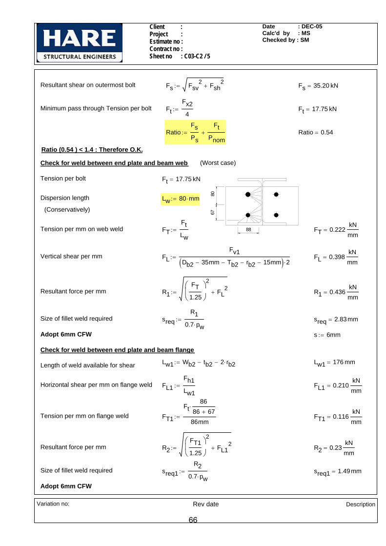
Resultant shear on outermost bolt Fs Fsv2 Fsh
2+:= Fs 35.20 kN=
Minimum pass through Tension per bolt FtFx24
:= Ft 17.75 kN=
RatioFsPs
FtPnom
+:= Ratio 0.54=
Ratio (0.54 ) < 1.4 : Therefore O.K.
Check for weld between end plate and beam web (Worst case)
88
6780
Tension per bolt Ft 17.75 kN=
Dispersion length Lw 80 mm⋅:=
(Conservatively)
Tension per mm on web weld FTFtLw
:= FT 0.222kNmm
=
Vertical shear per mm FLFv1
Db2 35mm− Tb2− rb2− 15mm−( ) 2⋅:= FL 0.398
kNmm
=
Resultant force per mm R1FT
1.25
⎛⎜⎝
⎞
⎠
2
FL2
+:= R1 0.436kNmm
=
Size of fillet weld required sreqR1
0.7 pw⋅:= sreq 2.83mm=
Adopt 6mm CFW s 6mm:=
Check for weld between end plate and beam flange
Lw1 Wb2 tb2− 2 rb2⋅−:= Lw1 176 mm=Length of weld available for shear
Horizontal shear per mm on flange weld FL1Fh1Lw1
:= FL1 0.210kNmm
=
Tension per mm on flange weld FT1
Ft86
86 67+⋅
86mm:= FT1 0.116
kNmm
=
Resultant force per mm R2FT11.25
⎛⎜⎝
⎞
⎠
2
FL12
+:= R2 0.23kNmm
=
Size of fillet weld required sreq1R2
0.7 pw⋅:= sreq1 1.49mm=
Adopt 6mm CFW
Variation no: Rev date Description
66
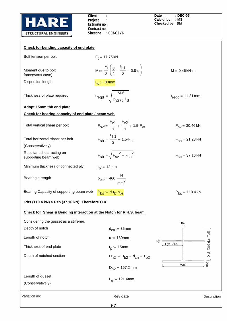
Client : Project : Estimate no : Contract no : Sheet no : C03-C2 / 6
Date : DEC-05Calc'd by : MSChecked by : SM
Check for bending capacity of end plate
Bolt tension per bolt Ft 17.75 kN=
Moment due to boltforce(worst case)
MFt2
g2
tb12
− 0.8 s⋅−⎛⎜⎝
⎞
⎠⋅:= M 0.46kN m⋅=
Dispersion length Ld 80mm:=
Thickness of plate required treqdM 6⋅
py275 Ld⋅:= treqd 11.21 mm=
Adopt 15mm thk end plate
Check for bearing capacity of end plate / beam web
Total vertical shear per bolt FsvFv1n
Fv2n
+ 1.5 Fvt⋅+:= Fsv 30.46 kN=
Total horizontal shear per bolt FshFh1
21.5 Fht⋅+:= Fsh 21.28 kN=
(Conservatively)
Resultant shear acting on supporting beam web Fsb Fsv
2 Fsh2
+:= Fsb 37.16 kN=
Minimum thickness of connected ply tb 12mm:=
Bearing strength pbs 460N
mm2⋅:=
Bearing Capacity of supporting beam web Pbs d tb⋅ pbs⋅:= Pbs 110.4 kN=
Pbs (110.4 kN) > Fsb (37.16 kN): Therefore O.K.
Check for Shear & Bending interaction at the Notch for R.H.S. beam
tb2
Dn2=
(Db2
-dcn
-Tb2
)Tb
2Wb2
tg
Lg=121.4
Considering the gusset as a stiffener,
Depth of notch dcn 35mm:=
Length of notch c 160mm:=
Thickness of end plate tp 15mm:=
Depth of notched section Dn2 Db2 dcn− Tb2−:=
Dn2 157.2 mm=
Length of gussetLg 121.4mm:=
(Conservatively)
Variation no: Rev date Description
67
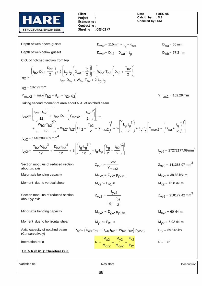
Client : Project : Estimate no : Contract no : Sheet no : C03-C2 / 7
Date : DEC-05Calc'd by : MSChecked by : SM
Depth of web above gusset Dwa 115mm tg− dcn−:= Dwa 65 mm=
Depth of web below gusset Dwb Dn2 Dwa− tg−:= Dwb 77.2mm=
C.G. of notched section from top
yt2
tb2 Dn2⋅Dn2
2⋅
⎛⎜⎝
⎞
⎠2 Lg tg⋅ Dwa
tg2
+⎛⎜⎝
⎞
⎠⋅
⎡⎢⎣
⎤⎥⎦
⋅+ Wb2 Tb2⋅ Dn2Tb2
2+
⎛⎜⎝
⎞
⎠⋅
⎡⎢⎣
⎤⎥⎦
+
tb2 Dn2⋅ Wb2 Tb2⋅+ 2 Lg⋅ tg⋅+:=
yt2 102.29 mm=
Ymax2 max Db2 dcn− yt2− yt2,( ):= Ymax2 102.29 mm=
Taking second moment of area about N.A. of notched beam
Ixx2tb2 Dn2
3⋅
12tb2 Dn2⋅ Ymax2
Dn22
−⎛⎜⎝
⎞
⎠
2
⋅
⎡⎢⎢⎣
⎤⎥⎥⎦
+
⎡⎢⎢⎣
⎤⎥⎥⎦
Wb2 Tb23
⋅
12
⎛⎜⎜⎝
⎞
⎠Wb2 Tb2⋅ Dn2
Tb22
+ Ymax2−⎛⎜⎝
⎞
⎠
2
⋅+ 2Lg tg
3⋅
12
⎛⎜⎜⎝
⎞
⎠Lg tg⋅ Ymax2 Dwa
tg2
+⎛⎜⎝
⎞
⎠−
⎡⎢⎣
⎤⎥⎦
2
⋅+
⎡⎢⎢⎣
⎤⎥⎥⎦
⋅++
...:=
Ixx2 14462093.89 mm4=
Iyy2Tb2 Wb2
3⋅
12
Dn2 tb23
⋅
12+ 2
tg Lg3
⋅
12
⎛⎜⎜⎝
⎞
⎠tg Lg⋅
Lg2
tb22
+⎛⎜⎝
⎞
⎠
2
⋅+
⎡⎢⎢⎣
⎤⎥⎥⎦
⋅+:= Iyy2 27272177.09 mm4=
Section modulus of reduced section about xx axis
Zxx2Ixx2
Ymax2:= Zxx2 141386.07 mm3
=
Major axis bending capacity Mcx2 Zxx2 py275⋅:= Mcx2 38.88 kN m⋅=
Moment due to vertical shear Mx2 Fv1 c⋅:= Mx2 16.8kN m⋅=
Section modulus of reduced section about yy axis
Zyy2Iyy2
Lgtb22
+
:= Zyy2 218177.42 mm3=
Minor axis bending capacity Mcy2 Zyy2 py275⋅:= Mcy2 60 kN m⋅=
Moment due to horizontal shear My2 Fh1 c⋅:= My2 5.92kN m⋅=
Axial capacity of notched beam(Conservatively)
Pt2 Dwa tb2⋅ Dwb tb2⋅+ Wb2 Tb2⋅+( ) py275⋅:= Pt2 897.45 kN=
Interaction ratio RMx2Mcx2
My2Mcy2
+Fx2Pt2
+:= R 0.61=
1.0 > R (0.61 ): Therefore O.K.
Variation no: Rev date Description
68

Client : Project : Estimate no : Contract no : Sheet no :C04-C1/ 1
Date : DEC-05 Calc'd by : MS Checked by : SM
CONNECTION NO - C04-C1
LOADS:
305X305X118 UC
Compression Fc 900 kN⋅:=
Major axis moment Mz 300 kN⋅ m⋅:=
650
550 7575 305X
305X
118
UC
150
200
150
300
BASE PLATE 700X650X60 THK30 THK NON-CEMENTITIOUS
NON-SHRINK GROUT
GROUT HOLES 50 DIA (TYP)
6A A
SECTION A-A
WASHER PLATE 120X120X20THK120
(TYP)(TYP)
(TYP
)
NOTES:-
All bolts are M24 grade 8.8 holding down bolts in 30mm dia holes.
All main steels & fittings are S355.
Variation no:
Rev date
Description
69
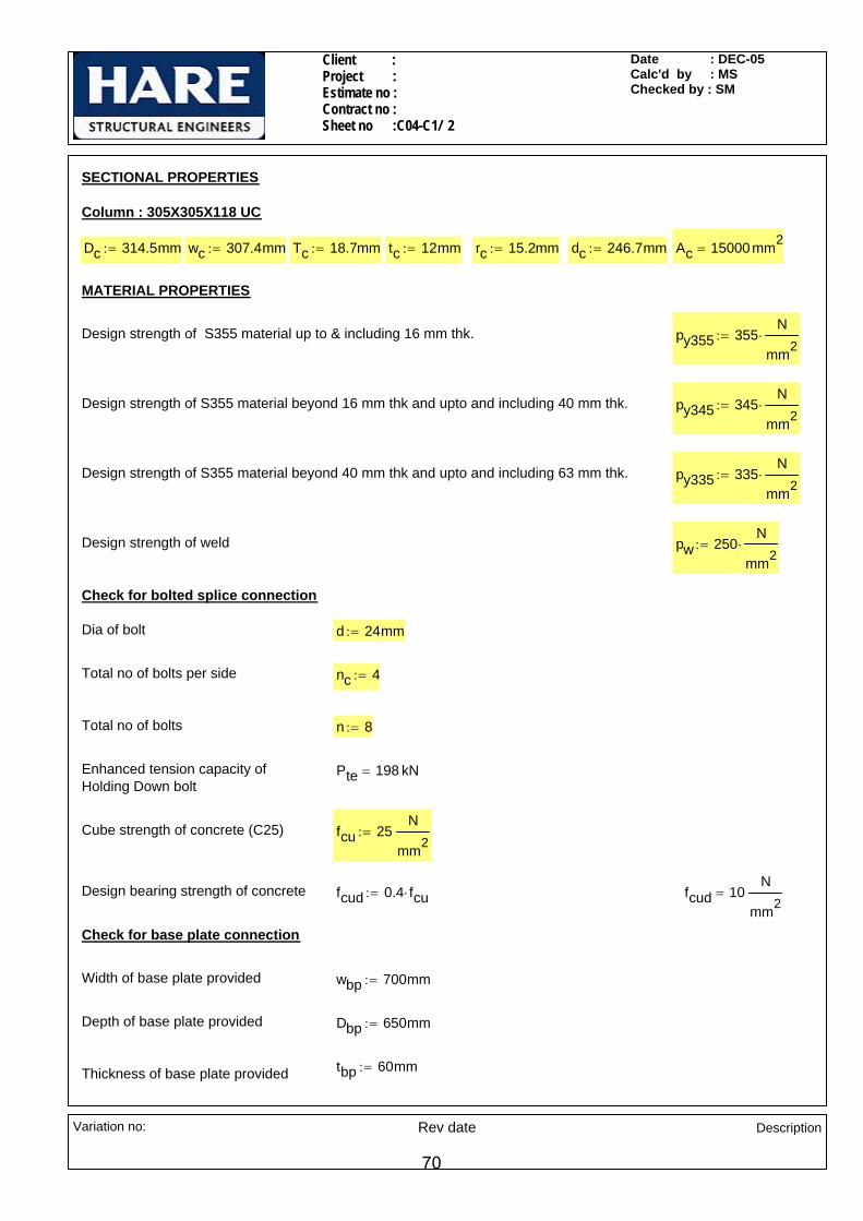
Client : Project : Estimate no : Contract no : Sheet no :C04-C1/ 2
Date : DEC-05 Calc'd by : MS Checked by : SM
SECTIONAL PROPERTIES
Column : 305X305X118 UC
Dc 314.5mm:= wc 307.4mm:= Tc 18.7mm:= tc 12mm:= rc 15.2mm:= dc 246.7mm:= Ac 15000 mm2=
MATERIAL PROPERTIES
Design strength of S355 material up to & including 16 mm thk. py355 355N
mm2⋅:=
Design strength of S355 material beyond 16 mm thk and upto and including 40 mm thk. py345 345N
mm2⋅:=
Design strength of S355 material beyond 40 mm thk and upto and including 63 mm thk. py335 335N
mm2⋅:=
Design strength of weld pw 250N
mm2⋅:=
Check for bolted splice connection
Dia of bolt d 24mm:=
Total no of bolts per side nc 4:=
Total no of bolts n 8:=
Enhanced tension capacity of Holding Down bolt
Pte 198 kN=
Cube strength of concrete (C25) fcu 25N
mm2:=
Design bearing strength of concrete fcud 0.4 fcu⋅:= fcud 10N
mm2=
Check for base plate connection
Width of base plate provided wbp 700mm:=
Depth of base plate provided Dbp 650mm:=
tbp 60mm:=Thickness of base plate provided
Variation no:
Rev date
Description
70
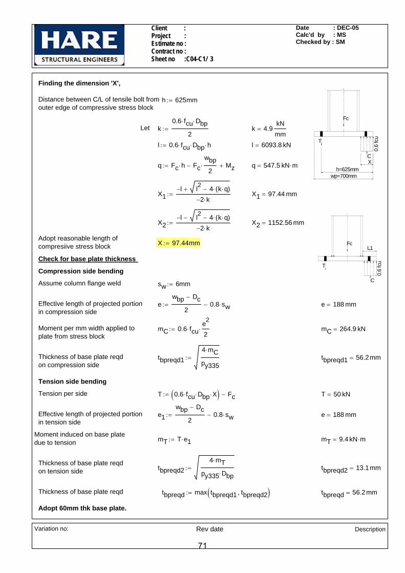
Client : Project : Estimate no : Contract no : Sheet no :C04-C1/ 3
Date : DEC-05 Calc'd by : MS Checked by : SM
Finding the dimension 'X',
0.6
fcu
C
T
Fc
h=625mmwp=700mm
X
Distance between C/L of tensile bolt from outer edge of compressive stress block
h 625mm:=
Let k0.6 fcu⋅ Dbp⋅
2:= k 4.9
kNmm
=
l 0.6 fcu⋅ Dbp⋅ h⋅:= l 6093.8 kN=
q Fc h⋅ Fcwbp
2⋅− Mz+:= q 547.5 kN m⋅=
X1l− l2 4 k q⋅( )⋅−+
2− k⋅:= X1 97.44 mm=
0.6
fcu
C
T
FcL1
X2l− l2 4 k q⋅( )⋅−−
2− k⋅:= X2 1152.56 mm=
Adopt reasonable length of compresiive stress block X 97.44mm:=
Check for base plate thickness
Compression side bending
Assume column flange weld sw 6mm:=
Effective length of projected portionin compression side
ewbp Dc−
20.8 sw⋅−:= e 188 mm=
Moment per mm width applied to plate from stress block
mC 0.6 fcu⋅e2
2⋅:= mC 264.9 kN=
Thickness of base plate reqdon compression side
tbpreqd14 mC⋅
py335:= tbpreqd1 56.2mm=
Tension side bending
Tension per side T 0.6 fcu⋅ Dbp⋅ X⋅( ) Fc−:= T 50 kN=
Effective length of projected portionin tension side
e1wbp Dc−
20.8 sw⋅−:= e 188 mm=
Moment induced on base plate due to tension mT T e1⋅:= mT 9.4 kN m⋅=
Thickness of base plate reqdon tension side tbpreqd2
4 mT⋅
py335 Dbp⋅:= tbpreqd2 13.1mm=
Thickness of base plate reqd tbpreqd max tbpreqd1 tbpreqd2,( ):= tbpreqd 56.2mm=
Adopt 60mm thk base plate.
Variation no:
Rev date
Description
71

Client : Project : Estimate no : Contract no : Sheet no :C04-C1/ 4
Date : DEC-05 Calc'd by : MS Checked by : SM
Check for holding down bolts
Tension acting each bolt FtTnc
:= Ft 12.5kN=
Ft (12.51 kN) < Pte (198 kN): Therefore O.K.
Check for conical pull out of tension bolts
(From steel designer's manual, P.No.796, Table 27.2)Surface area of conical pull-out Acp 525800mm2
:=
Surface stress due to conical pull-out vcpFt
Acp:= vcp 0.02
N
mm2=
(From BS8110-1:1997,P.No.32,table 3.8)vc 0.34
N
mm2:=Design shear stress of concrete
vcp (0.02 N/mm^2) < vc (0.34 N/mm^2): Therefore O.K.
Check for punching shear of concrete section
Anchorage length of holding down bolts provided L 300mm:=
Washer plate width bap 120mm:=
Washer plate length lap 120mm:=
Washer plate thickness tap 20mm:=
Washer plate perimeters overlap.
Perimeter around the anchor plate Lp 2 120mm bap+( )⋅ 2 3 L⋅( )⋅+ 2 3 L⋅( )⋅+:= Lp 4080 mm=
Average shear stress over effective depth
fvT
Lp L⋅:= fv 0.04
N
mm2=
fv (0.04 N/mm^2) < vc (0.34 N/mm^2): Therefore O.K.
Check for washer plate bearing on concrete
ø of tube=50
ø of bolt=24B
72.85
120
120
60
Awp bap lap⋅:= Awp 14400 mm2=Area of washer plate
Diameter of tube Dtb 50mm:=
Area of tube Atbπ Dtb
2⋅
4:= Atb 1963.5 mm2
=
Bearing area of concrete @ washer plate location
Abcw Awp Atb−:= Abcw 12436.5 mm2=
Variation no:
Rev date
Description
72

Client : Project : Estimate no : Contract no : Sheet no :C04-C1/ 5
Date : DEC-05 Calc'd by : MS Checked by : SM
Bearing stress on concrete @ washer plate location fcbw
FtAbcw
:= fcbw 1.01N
mm2=
fcbw (1.01 N/mm^2) < fcud (10 N/mm^2): Therefore O.K.
ø of tube=50
ø of bolt=24B
72.85
120
120
60
Check for washer plate bending
Max length of bending lbw 60mm( )2bap2
⎛⎜⎝
⎞
⎠
2
+d2
−:= lbw 72.85 mm=
Length of loading llw lbwDtb d−
2
⎛⎜⎝
⎞
⎠−:= llw 59.9mm=
Moment acting @ B per mm Mwp fcbw llw⋅ lbw llw−( )llw2
+⎡⎢⎣
⎤⎥⎦
⋅:= Mwp 2.6kN mm⋅
mm=
Moment capacity of washer plate per mm
Mcwptap
2
6py345⋅:= Mcwp 23
kN mm⋅
mm=
Mwp (2.58 kNmm/mm) < Mcwp(23 kNmm/mm): Therefore O.K.
Weld between column flange and base plate
Length available for weld Lweld 2 wc⋅ tc− 2 rc⋅−:= Lweld 572.4 mm=
Net force acting in the column flange FwMz
Dc Tc−Fc
wc Tc⋅
Ac⋅−:= Fw 669.3 kN=
Fcf wc Tc⋅ py345⋅:= Fcf 1983.2 kN=Capacity of column flange
Force acting on the flange weld per mm
FTmin Fw Fcf,( )
Lweld:= FT 1.2
kNmm
=
Size of weld required swFT
1.25 0.7⋅ pw⋅:= sw 5.35mm=
Adopt 6mm CFW allround.
Variation no:
Rev date
Description
73

© MasterKey Joints - Project Title C:\Documents and Settings\SENTHIL\Desktop\C04-2005
25125William Hare LimitedBrandlesholme House, Brandlesholme RoadBury, Manchester BL8 1JJwww.williamhare.comTel: 0161 6090000 Fax: 0161 6090409
Job RefSheetMade byDateCheckedApproved
: : C04-C2 / 001: SSK: December, 2005 / Ver. 2004.10: SM:
© Civil and Structural Computer Services Limited, 1 Circular Road, Newtownabbey, Co. Antrim BT37 0RA, Tel: 028 9036 5950 Fax: 028 9036 5102
C04 - C2 - BASE PLATE CONNECTIONBase-Plate Connection
8fw8fw
600
200
200
200
200
600
75 75
Base-Plate 600 x 600 x 50 mm (141 kg)With 6 No. 36 mm holesFor 30 mm Grade 8.8 Bolts.
25 grout
700
203x203 UC 52 [S 275]
Washers 120 x 120 x 25 mm thick with 50 mm VoidAll Plates S 275. All Welds Grade 42 (direct bearing assumed.)
Loading Case 01Basic Data
Applied Forces at Interface - - Case 01Resultant Forces M, Fv, F Moment +40.0 kNm, Shear +0.0 kN, Axial +0.0 kN
(Left side in tension, Axial Compression)
Basic DimensionsColumn: 203x203 UC 52 [28] D=206.2, B=204.3, T=12.5, t=7.9, r=10.2, py=275Data grout, Fcu, Fcv, Py, Slope 25 N/mm², 25 N/mm², 0.35 N/mm², 255 N/mm², 45 deg to verticalDesign to BS 5950-1: 2000 and the SCI Green Book:
Joints in Steel Construction : Moment Connections: SCI-P-207/95Column Capacities Mc, Fvc, Fc 156.0 kN.m, 268.8 kN, 1822.7 kN Mc = 156.0 kN.m OK
Summary of Results (Unity Ratios)Concrete Pressure (under axial only) 0.00 OKBase-Plate thickness in Compression (under axial only) 0.00 OKBolt Tension 0.10 OKBase-Plate thickness in Compression 0.48 OKPlate Tension Bending 0.31 0.31 OKConcrete Embedment 0.13 OKWasher Bending & Shear 0.00, 0.04 0.04 OKPullout Cones 0.03, 0.07 0.07 OKFlange & Web Welds 0.36 0.36 OK
74

© MasterKey Joints - Project Title C:\Documents and Settings\SENTHIL\Desktop\C04-2005
25125William Hare LimitedBrandlesholme House, Brandlesholme RoadBury, Manchester BL8 1JJwww.williamhare.comTel: 0161 6090000 Fax: 0161 6090409
Job RefSheetMade byDateCheckedApproved
: : C04/C2 / 002: SSK: December, 2005 / Ver. 2004.10: SM:
© Civil and Structural Computer Services Limited, 1 Circular Road, Newtownabbey, Co. Antrim BT37 0RA, Tel: 028 9036 5950 Fax: 028 9036 5102
Loading Case 02Basic Data
Applied Forces at Interface - - Case 02Resultant Forces M, Fv, F Moment +0.0 kNm, Shear +268.0 kN, Axial +1425.0 kN
(Axial Compression)Column Capacities Mc, Fvc, Fc 156.0 kN.m, 268.8 kN, 1822.7 kN Fvc = 268.8 kN OK
Summary of Results (Unity Ratios)Concrete Pressure 0.40 OKBase-Plate thickness in Compression 0.85 OKHorizontal Shear 0.22 OKFlange & Web Welds 0.66 0.66 OK
75

© MasterKey Joints - Project Title C:\Documents and Settings\SENTHIL\Desktop\C04-2005
25125William Hare LimitedBrandlesholme House, Brandlesholme RoadBury, Manchester BL8 1JJwww.williamhare.comTel: 0161 6090000 Fax: 0161 6090409
Job RefSheetMade byDateCheckedApproved
: : C04/C2 / 003: SSK: December, 2005 / Ver. 2004.10: SM:
© Civil and Structural Computer Services Limited, 1 Circular Road, Newtownabbey, Co. Antrim BT37 0RA, Tel: 028 9036 5950 Fax: 028 9036 5102
Loading Case 03Basic Data
Applied Forces at Interface - - Case 03Resultant Forces M, Fv, F Moment +0.0 kNm, Shear +0.0 kN, Axial -1225.0 kN
(Axial Up-Lift)Column Capacities Mc, Fvc, Fc 156.0 kN.m, 268.8 kN, 1822.7 kN Fc = 1822.7 kN OK
Summary of Results (Unity Ratios)Bolt Tension 0.81 OKPlate Tension Bending 0.89 0.89 OKConcrete Embedment 0.76 OKWasher Bending & Shear 0.00, 0.36 0.36 OKPullout Cones 0.23, 0.54, 0.85 0.85 OKFlange & Web Welds 0.83, 0.53 0.83 OK
76
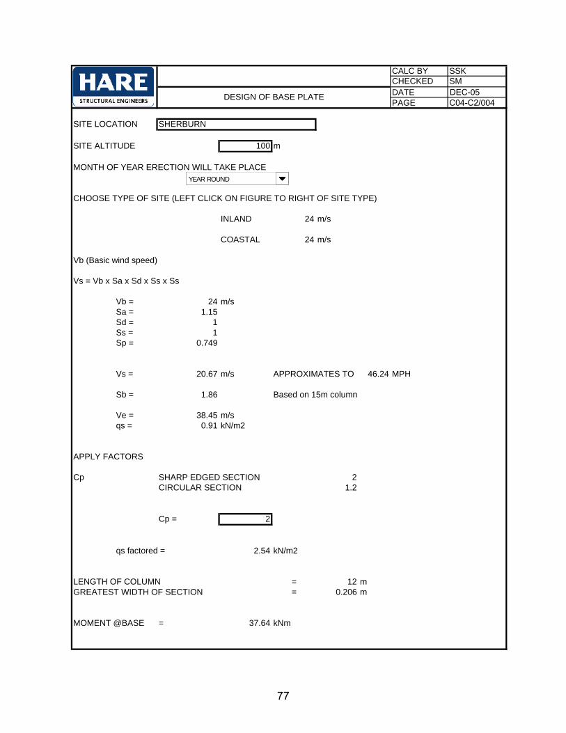
CALC BY SSKCHECKED SMDATE DEC-05PAGE C04-C2/004
SITE LOCATION SHERBURN
SITE ALTITUDE 100 m
MONTH OF YEAR ERECTION WILL TAKE PLACE
CHOOSE TYPE OF SITE (LEFT CLICK ON FIGURE TO RIGHT OF SITE TYPE)
INLAND 24 m/s
COASTAL 24 m/s
Vb (Basic wind speed)
Vs = Vb x Sa x Sd x Ss x Ss
Vb = 24 m/sSa = 1.15Sd = 1Ss = 1Sp = 0.749
Vs = 20.67 m/s APPROXIMATES TO 46.24 MPH
Sb = 1.86 Based on 15m column
Ve = 38.45 m/sqs = 0.91 kN/m2
APPLY FACTORS
Cp SHARP EDGED SECTION 2CIRCULAR SECTION 1.2
Cp = 2
qs factored = 2.54 kN/m2
LENGTH OF COLUMN = 12 mGREATEST WIDTH OF SECTION = 0.206 m
MOMENT @BASE = 37.64 kNm
BRITISH GYPSUM - DSG BUILDING
DESIGN OF BASE PLATE
YEAR ROUND
77

CALC BY SSKCHECKED SMDATE DEC'05PAGE C04-C2/005
BRITISH GYPSUM - DSG BUILDING
DESIGN OF BASE PLATE
BASE DIMENSIONS
TENSION/BOLT X-X = 27.88 kN=
TENSION/BOLT Y-Y 47.05 kN
HOLDING DOWN BOLT DIAMETER = 30 mm=
HOLDING DOWN BOLT GRADE 8.8
TENSILE CAPACITY = 314 kN/ BOLT
X-X AXIS BOLTS OK
Y-Y AXIS BOLTS OK
BEARING OF WEDGES ON CONCRETE
WIDTH OF WEDGE = 100 mm Note: Wedge minimum 100mm
BEARING LENGTH = 100 mm
COMPRESSIVE FORCE ACTING ON WEDGE/PACK ( X-X AXIS) = 83.64 kN
COMPRESSIVE FORCE ACTING ON WEDGE/PACK (Y-Y AXIS) = 94.10 kN
BEARING ON CONCRETE X-X = 8.36 N/mm2
BEARING ON CONCRETE Y-Y = 9.41 N/mm2
CONCRETE GRADE = 25 N/mm2
600
200
200
200
200
600
75 75450
78

CALC BY SSKCHECKED SMDATE DEC'05PAGE C04-C2/006
BRITISH GYPSUM - DSG BUILDING
DESIGN OF BASE PLATE
ALLOWABLE STRESS TO CONCRETE = 10 N/mm2
X-X AXIS BEARING TO CONCRETE OK
Y-Y AXIS BEARING TO CONCRETE OK
BASE PLATE BENDING
X-X AXIS
la = 67.10 mm
DISPERSAL LENGTH = 102.15 mm
THICKNESS OF BASE PLATE = 50 mm
THICKNESS OF BASE PLATE REQUIRED = 15.18 mm
BASEPLATE OK
WASHER PLATE BEARING ON CONCRETE
THICKNESS OF WASHER PLATE= 25 mmMINIMUM RECOMMENDED THICKNESS = 25
GRADE OF WASHER PLATE = 265 N/mm2
WIDTH OF WASHER PLATE = 120
LENGTH OF WASHER PLATE = 120 mm
AREA OF WASHER PLATE = 14400 mm2
DIAMETER OF CONE/TUBE = 50 mm AT INTERFACE WITH WASHER PACK
AREA OF CONE/TUBE = 1963.50 mm2
AREA BEARING ON CONCRETE = 12436.50 mm2
ALLOWABLE STRESS TO CONCRETE = 10 N/mm2
BEARING ON CONCRETE X-X = 2.24 N/mm2
BEARING ON CONCRETE Y-Y = 3.78 N/mm2
X-X AXIS BEARING TO CONCRETE OK
Y-Y AXIS BEARING TO CONCRETE OK
79

CALC BY SSKCHECKED SMDATE DEC'05PAGE C04-C2/007
BRITISH GYPSUM - DSG BUILDING
DESIGN OF BASE PLATE
WASHER PLATE BENDING
WORST CASE CANTILEVER = 63.64 mm
LOADED LENGTH = 53.64 mm
MAXIMUM MOMENT = 7471.85 Nmm
MOMENT CAPACITY OF PLATE = 27604.17 Nmm OK
CONCRETE PULLOUT
CONICAL SURFACE AREA = 24297 cm2 FROM STEEL DESIGNERS MANUALFIFTH EDITION PAGE 796 TABLE 27.2
NOTE; IF VALUE IS TO THE RIGHT OF HEAVY ZIG-ZAG LINE, DOUBLE EFFECTIVE CONICAL SURFACE AREA
SURFACE STRESS = 0.15 N/mm2
ALLOWABLE CONCRETE SHEAR STRESS = 0.34 N/mm2 OK
PUNCHING SHEAR
EMBEDMENT LENGTH = = 700 mm
P = (12 X L) + Pap
Pap = 480 mm
P = 8880 mm
AVERAGE SHEAR STRESS = 0.008 N/mm2 OK
80
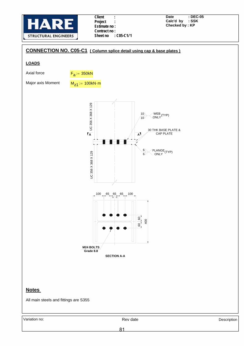
Client : Project : Estimate no : Contract no : Sheet no : C05-C1/ 1
Date : DEC-05Calc'd by : SSKChecked by : KP
CONNECTION NO. C05-C1 ( Column splice detail using cap & base plates )
LOADS
Axial force Fa 350kN:=
Major axis Moment Mz1 100kN m⋅:=
M24 BOLTSGrade 8.8
SECTION A-A
100 10065 6565
6060
30 THK BASE PLATE & CAP PLATEAA
UC
356
X 3
68 X
129
= =
400
(TYP)1010 WEB
ONLY
UC
356
X 3
68 X
129
66
FLANGE ONLY
(TYP)
Notes
All main steels and fittings are S355
Variation no: Rev date
Description
81

Client : Project : Estimate no : Contract no : Sheet no : C05-C1/ 2
Date : DEC-05Calc'd by : SSKChecked by : KP
Sectional properties
ColumnUC 356 x 368 x 129 Dc1 355.6mm:= Wc1 368.6mm:= Tc1 17.5mm:= tc1 10.4mm:= rc1 15.2mm:=
Ac1 16400mm2:=
Material Properties
Design strength of S355 materialUp to & including 16 thk
py355 355N
mm2⋅:=
Design strength of S345 materialbeyond 16thk and up to & including40mm thk
py345 345N
mm2⋅:=
Bearing Strength of S355 material pbs355 550N
mm2:=
Design strength of fillet weld for S355 material
pw 250N
mm2⋅:=
Check for bolts
Bolt diameter d 24mm:=
Diameter of hole Dh 26mm:=
Total number of bolts n 8:=
Shear Capacity of bolt Ps 132kN:=
Tensile Capacity of bolt Pnom 158kN:=
Bolt lever arm distance( Taking rotation about c/l of column flanges )
Rr 71.55 136.55 201.55 266.55( ) mm⋅:=
Sectional modulus of bolt group Zbg1 20
3
n
Rr0 n,⎛⎝
⎞⎠
2∑=
Rr0 3,
⋅:= Zbg1 1016.22 mm=
Tension per bolt due to major axis moment
Ftm1Mz1Zbg1
:= Ftm1 98.40 kN=
Variation no: Rev date
Description
82

Client : Project : Estimate no : Contract no : Sheet no : C05-C1/ 3
Date : DEC-05Calc'd by : SSKChecked by : KP
Tension per bolt due to moment Ftt Ftm1:= Ftt 98.40 kN=
Tension per bolt due to axial FatFan
:= Fat 43.75 kN=
Total tension per bolt due to moment & axial
Ft Ftt Fat+:= Ft 142.15 kN= > Pnom 158kN:=
Therefore OK
80.10
146.
37
Check for weld b/w column flanges to base plate
Check for tension
Maximum tension on bolt Ft 142.15 kN=
Tension on column flange FtfFt 146.37⋅ mm⋅
146.37 80.10+( ) mm⋅:= Ftf 91.88 kN=
Tension per mm on weld FTFtf
146.37 mm⋅:= FT 0.628
kNmm
=
Size of fillet weld required sreqdFT
0.7 pw⋅ 1.25⋅:= sreqd 2.87mm=
Check for compression
Compressive force on columnflange due to axial
FcaWc1 Tc1⋅
Ac1Fa⋅:= Fca 137.7 kN=
Max. compression in flangeof column due to moment and axial
Fc
2 Ftt⋅
0
3
n
Rr0 n,∑=
⎛⎜⎜⎝
⎞
⎠
⋅
Rr0 3,
Fca+:= Fc 636.9 kN=
Compression per mm FTcFc
2 Wc1⋅ 2 rc1⋅− tc1−:= FTc 0.91
kNmm
=
Size of fillet weld required sreqdFTc
0.7 pw⋅ 1.25⋅:= sreqd 4.18mm=
Adopt 6mm CFW
Variation no: Rev date
Description
83

Client : Project : Estimate no : Contract no : Sheet no : C05-C1/ 4
Date : DEC-05Calc'd by : SSKChecked by : KP
Weld b/w column web to base plate
Dispersion length Lweld 65 mm⋅:=
Tension acting on 2nd bolt row Ft2 Ftm1
Rr0 2,
Rr0 3,
⋅ Fat+:= Ft2 118.16 kN=
Tension per mm on weld FTFt2
Lweld:= FT 1.818
kNmm
=
Size of weld required sreqdFT
0.7 pw⋅ 1.25⋅:= sreqd 8.31mm=
Adopt 10mm CFW
Check for base/cap plate
65
46.8
Moment due to bolt force MFt2
46.8 mm⋅( )⋅:= M 3.326 kN m⋅=
Dispersion length Ld 65mm:=
Thickness of plate required treqdM 6⋅
py345 Ld⋅:= treqd 29.83 mm=
Adopt 30mm thk base/cap plate
Variation no: Rev date
Description
84
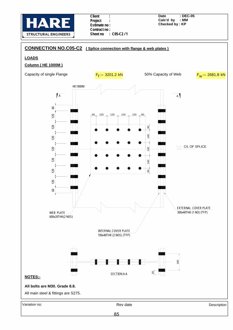
Client : Project : Estimate no : Contract no : Sheet no : C05-C2 / 1
Date : DEC-05Calc'd by : MMChecked by : KP
6014
014
0
120
120
WEB PLATE600x20THK(2 NOS)
SECTION A-A
INTERNAL COVER PLATE
120
60
100x40THK (2 NOS) (TYP)
140
60
50
120
120
120
120
60
HE1000M
A
120 120 120 120 6060
EXTERNAL COVER PLATE300x40THK (1 NO) (TYP)
180
C/L OF SPLICE
CONNECTION NO.C05-C2 ( Splice connection with flange & web plates )
LOADS
Column ( HE 1000M )
Capacity of single Flange Ff 3201.2 kN⋅:= 50% Capacity of Web Fw 2681.8 kN⋅:=
NOTES:-
All bolts are M30. Grade 8.8.
All main steel & fittings are S275.
Variation no: Rev date Description
85
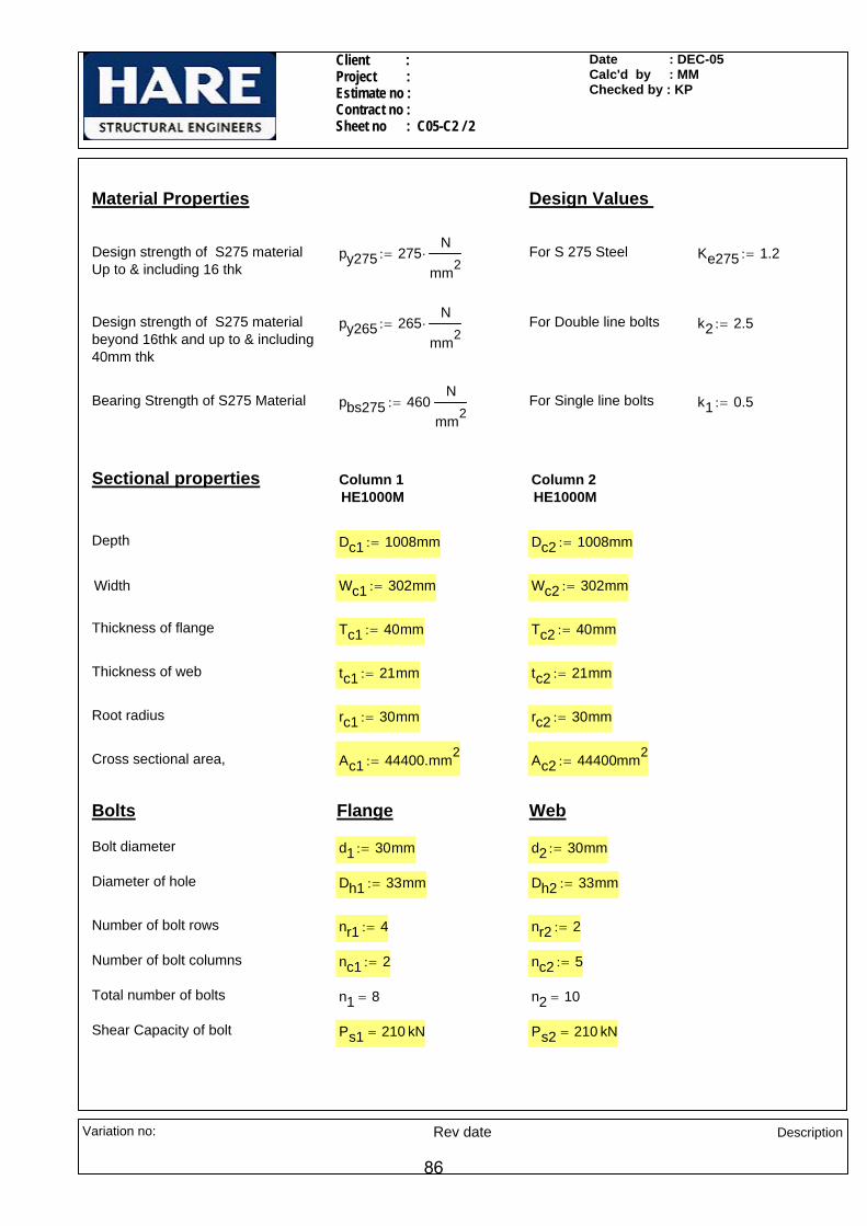
Client : Project : Estimate no : Contract no : Sheet no : C05-C2 / 2
Date : DEC-05Calc'd by : MMChecked by : KP
Material Properties Design Values
Design strength of S275 materialUp to & including 16 thk
py275 275N
mm2⋅:= For S 275 Steel Ke275 1.2:=
Design strength of S275 materialbeyond 16thk and up to & including40mm thk
py265 265N
mm2⋅:= For Double line bolts k2 2.5:=
Bearing Strength of S275 Material pbs275 460N
mm2:= For Single line bolts k1 0.5:=
Sectional properties Column 1HE1000M
Column 2HE1000M
Depth Dc1 1008mm:= Dc2 1008mm:=
Width Wc1 302mm:= Wc2 302mm:=
Thickness of flange Tc1 40mm:= Tc2 40mm:=
Thickness of web tc1 21mm:= tc2 21mm:=
Root radius rc1 30mm:= rc2 30mm:=
Cross sectional area, Ac1 44400.mm2:= Ac2 44400mm2
:=
Bolts Flange Web
Bolt diameter d1 30mm:= d2 30mm:=
Diameter of hole Dh1 33mm:= Dh2 33mm:=
Number of bolt rows nr1 4:= nr2 2:=
Number of bolt columns nc1 2:= nc2 5:=
Total number of bolts n1 8= n2 10=
Shear Capacity of bolt Ps1 210 kN= Ps2 210 kN=
Variation no: Rev date Description
86
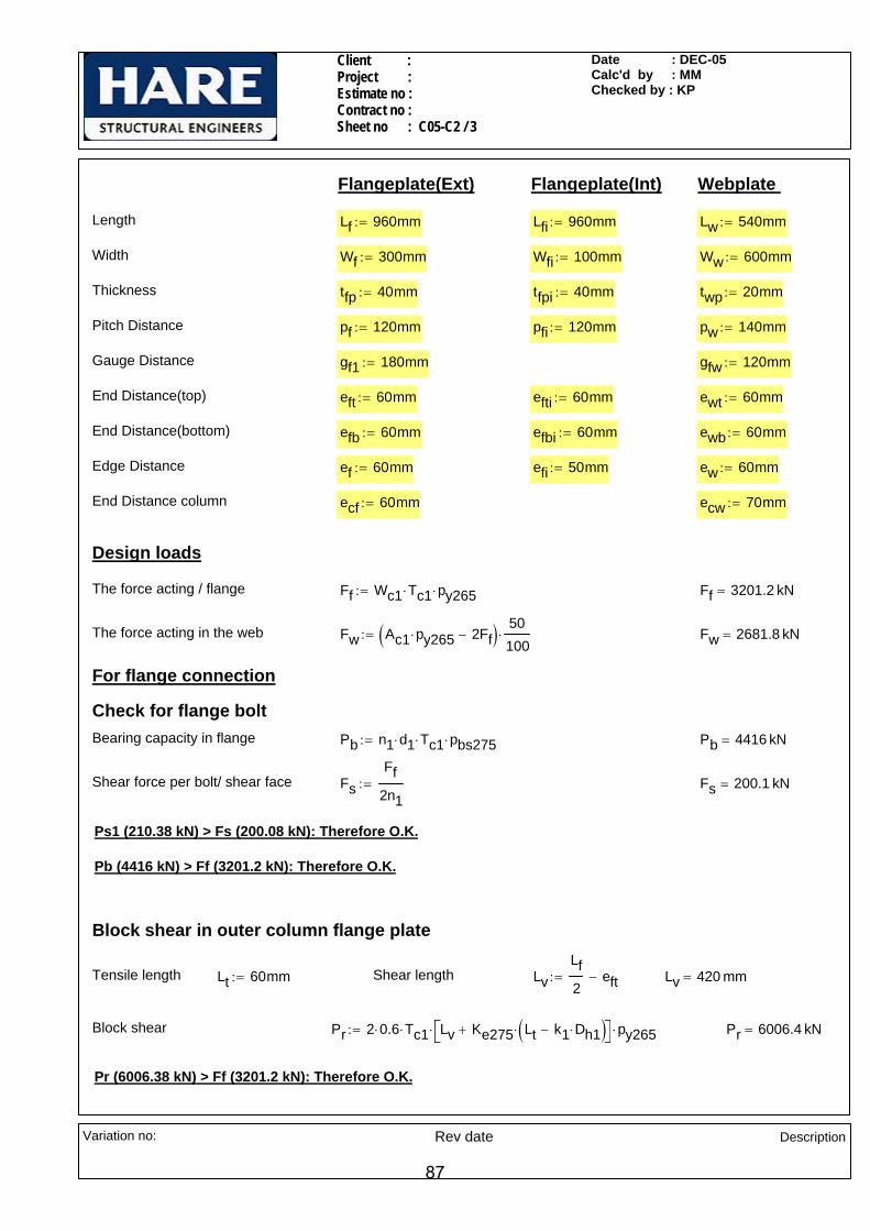
Client : Project : Estimate no : Contract no : Sheet no : C05-C2 / 3
Date : DEC-05Calc'd by : MMChecked by : KP
Flangeplate(Ext) Flangeplate(Int) Webplate
Length Lf 960mm:= Lfi 960mm:= Lw 540mm:=
Width Wf 300mm:= Wfi 100mm:= Ww 600mm:=
Thickness tfp 40mm:= tfpi 40mm:= twp 20mm:=
Pitch Distance pf 120mm:= pfi 120mm:= pw 140mm:=
Gauge Distance gf1 180mm:= gfw 120mm:=
End Distance(top) eft 60mm:= efti 60mm:= ewt 60mm:=
End Distance(bottom) efb 60mm:= efbi 60mm:= ewb 60mm:=
Edge Distance ef 60mm:= efi 50mm:= ew 60mm:=
End Distance column ecf 60mm:= ecw 70mm:=
Design loads
The force acting / flange Ff Wc1 Tc1⋅ py265⋅:= Ff 3201.2 kN=
The force acting in the web Fw Ac1 py265⋅ 2Ff−( ) 50100⋅:= Fw 2681.8 kN=
For flange connection
Check for flange boltBearing capacity in flange Pb n1 d1⋅ Tc1⋅ pbs275⋅:= Pb 4416 kN=
Shear force per bolt/ shear face FsFf
2n1:= Fs 200.1 kN=
Ps1 (210.38 kN) > Fs (200.08 kN): Therefore O.K.
Pb (4416 kN) > Ff (3201.2 kN): Therefore O.K.
Block shear in outer column flange plate
Tensile length Lt 60mm:= Shear length LvLf2
eft−:= Lv 420 mm=
Block shear Pr 2 0.6⋅ Tc1⋅ Lv Ke275 Lt k1 Dh1⋅−( )⋅+⎡⎣ ⎤⎦⋅ py265⋅:= Pr 6006.4 kN=
Pr (6006.38 kN) > Ff (3201.2 kN): Therefore O.K.
Variation no: Rev date Description
87
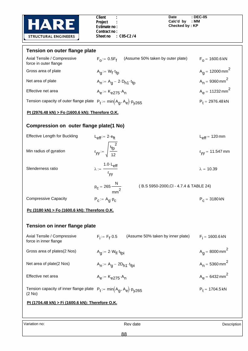
Client : Project : Estimate no : Contract no : Sheet no : C05-C2 / 4
Date : DEC-05Calc'd by : MMChecked by : KP
Tension on outer flange plateAxial Tensile / Compressive force in outer flange
Fo 0.5Ff:= (Assume 50% taken by outer plate) Fo 1600.6 kN=
Gross area of plate Ag Wf tfp⋅:= Ag 12000 mm2=
Net area of plate An Ag 2 Dh1⋅ tfp⋅−:= An 9360 mm2=
Effective net area Ae Ke275 An⋅:= Ae 11232 mm2=
Tension capacity of outer flange plate Pt min Ag Ae,( ) py265⋅:= Pt 2976.48 kN=
Pt (2976.48 kN) > Fo (1600.6 kN): Therefore O.K.
Compression on outer flange plate(1 No)
Effective Length for Buckling Leff 2 eft⋅:= Leff 120 mm=
Min radius of gyration ryytfp
2
12:= ryy 11.547 mm=
Slenderness ratio λ1.0 Leff⋅
ryy:= λ 10.39=
pc 265N
mm2= ( B.S 5950-2000,Cl - 4.7.4 & TABLE 24)
Compressive Capacity Pc Ag pc⋅:= Pc 3180 kN=
Pc (3180 kN) > Fo (1600.6 kN): Therefore O.K.
Tension on inner flange plate
Axial Tensile / Compressive force in inner flange
Fi Ff 0.5⋅:= (Assume 50% taken by inner plate) Fi 1600.6 kN=
Gross area of plates(2 Nos) Ag 2 Wfi⋅ tfpi⋅:= Ag 8000 mm2=
Net area of plate(2 Nos) An Ag 2Dh1 tfpi⋅−:= An 5360 mm2=
Effective net area Ae Ke275 An⋅:= Ae 6432 mm2=
Tension capacity of inner flange plate(2 No)
Pt min Ag Ae,( ) py265⋅:= Pt 1704.5 kN=
Pt (1704.48 kN) > Fi (1600.6 kN): Therefore O.K.
Variation no: Rev date Description
88

Client : Project : Estimate no : Contract no : Sheet no : C05-C2 / 5
Date : DEC-05Calc'd by : MMChecked by : KP
Compression on inner flange plate
Effective Length for Buckling Leff 2 efti⋅:= Leff 120 mm=
Min radius of gyration (ryy) ryytfpi
2
12:= ryy 11.547 mm=
Slenderness ratio ( λ) λ1.0 Leff⋅
ryy:= λ 10.39=
pc 265N
mm2= ( B.S 5950-2000,Cl - 4.7.4 & TABLE 24)
Compressive Capacity ( Pc) Pc Ag pc⋅:= Pc 2120 kN=
Pc (2120 kN) > Fi (1600.6 kN): Therefore O.K.
For web connection
Check for web bolt
Bearing capacity Pb n2 d2⋅ tc1⋅ pbs275⋅:= Pb 2898 kN=
Shear force per bolt/ shear face FsFw2n2
:= Fs 134.1 kN=
Pb (2898 kN) > Fw (2681.8 kN): Therefore O.K.
Ps2 (210.38 kN) > Fs (134.09 kN): Therefore O.K.
Block shear in column web
Shear length Lv 2 pw ecw+( ):= Lv 420 mm= k 4:=
Tensile length Lt nc2 1−( )gfw:= Lt 480 mm=
Block shear Pr 0.6 tc1⋅ Lv Ke275 Lt k Dh2⋅−( )⋅+⎡⎣ ⎤⎦⋅ py265⋅:= Pr 2796.75 kN=
Pr (2796.75 kN) > Fw (2681.8 kN): Therefore O.K.
Variation no: Rev date Description
89

Client : Project : Estimate no : Contract no : Sheet no : C05-C2 / 6
Date : DEC-05Calc'd by : MMChecked by : KP
Tension capacity of web plateAxial Tensile / Compressive force in web
Fw 2681.8 kN=
Gross area of plate Ag 2Ww twp⋅:= Ag 24000 mm2=
Net area of plate An Ag nc2 Dh2⋅ twp⋅−:= An 20700 mm2=
Effective net area Ae Ke275 An⋅:= Ae 24840 mm2=
Tension capacity of web Pt min Ag Ae,( ) py265⋅:= Pt 6360 kN=
Pt (6360 kN) > Fw (2681.8 kN): Therefore O.K.
Compression capacity of web plate
Effective Length for Buckling Leff 2 70⋅ mm:= Leff 140 mm=
Min radius of gyration (ryy) ryytwp
2
12:= ryy 5.774 mm=
Slenderness ratio ( λ) λ1.0 Leff⋅
ryy:= λ 24.25=
pc 258.4N
mm2= ( B.S 5950-2000,Cl - 4.7.4 & TABLE 24)
Compressive Capacity ( Pc) Pc Ag pc⋅:= Pc 6201.1 kN=
Pc (6201.07 kN) > Fw (2681.8 kN): Therefore O.K.
Variation no: Rev date Description
90

© MasterKey Joints
25125William Hare LimitedBrandlesholme House, Brandlesholme RoadBury, Manchester BL8 1JJwww.williamhare.comTel: 0161 6090000 Fax: 0161 6090409
Job RefSheetMade byDateCheckedApproved
: : C06 -C1 / 001: SM: DEC-05: KP:
© Civil and Structural Computer Services Limited, 1 Circular Road, Newtownabbey, Co. Antrim BT37 0RA, Tel: 028 9036 5950 Fax: 028 9036 5102
Connection-C06-C1Beam to Column Flange End-Plated Moment Connection
fpbw
8fw
6fw
110
110
110
110
140
110
110
200990
10
End-Plate 1000 x 300 x 25 mm (59 kg)14 No. M20 8.8 Bolts in 22 mm holes
120
Welds grd 42 Plates S 275Beam HE 1000 A 272.27 [S 275]Column HE 500 A 155.06 [S 275]Top 0 above top flange
Right Hand Side - Loading Case 01Basic Data
Applied Forces at Column/Right Rafter InterfaceResultant Forces M, Fv, F +400.0 kNm, +900.0 kN, +150.0 kNLoad directions Top of Joint in Tension, Rafter moving Down and in Compression.Design to BS 5950-1: 2000 and the SCI Green Book:
Joints in Steel Construction : Moment Connections: SCI-P-207/95
Basic DimensionsColumn-HE 500 A 155.06 [28] D=490, B=300, T=23, t=12, r=27.0, py=265Beam-HE 1000 A 272.27 [28] D=990, B=300, T=31, t=16.5, r=30.0, py=275Rafter Capacities Mc, Fvc, Fc 3526.7 kN.m, 2695.3 kN, 9538.1 kN Fvc = 2695.3 kN OK
Summary of Results (Unity Ratios)Moment Capacity 516.0 kNm (for 3 rows of bolts) 0.64 OKMoment Capacity 417.9 kNm (for the 2 rows of bolts required in the tension zone) 0.79 OKShear Capacity 0.87 OKFlange Welds 1.00, 0.63 1.00 OKWeb Welds 0.68, 0.80 0.80 OK
91

© MasterKey Joints
25125William Hare LimitedBrandlesholme House, Brandlesholme RoadBury, Manchester BL8 1JJwww.williamhare.comTel: 0161 6090000 Fax: 0161 6090409
Job RefSheetMade byDate DEC-05CheckedApproved
: : C06 -C1 / 002: SM:: KP:
© Civil and Structural Computer Services Limited, 1 Circular Road, Newtownabbey, Co. Antrim BT37 0RA, Tel: 028 9036 5950 Fax: 028 9036 5102
Right Hand Side - Loading Case 02Basic Data
Applied Forces at Column/Right Rafter InterfaceResultant Forces M, Fv, F +400.0 kNm, +900.0 kN, -150.0 kNLoad directions Top of Joint in Tension, Rafter moving Down and in Tension.Design to BS 5950-1: 2000 and the SCI Green Book:
Joints in Steel Construction : Moment Connections: SCI-P-207/95Rafter Capacities Mc, Fvc, Fc 3526.7 kN.m, 2695.3 kN, 9538.1 kN Fvc = 2695.3 kN OK
Summary of Results (Unity Ratios)Moment Capacity 656.1 kNm (for 5 rows of bolts) 0.72 OKMoment Capacity 549.8 kNm (for the 3 rows of bolts required in the tension zone) 0.86 OKShear Capacity 0.97 OKFlange Welds 1.00, 0.53 1.00 OKWeb Welds 0.72, 0.98 0.98 OK
92

© MasterKey Joints
25125William Hare LimitedBrandlesholme House, Brandlesholme RoadBury, Manchester BL8 1JJwww.williamhare.comTel: 0161 6090000 Fax: 0161 6090409
Job RefSheetMade byDateCheckedApproved
: : C06 -C1 / 003: SM: DEC-05: KP:
© Civil and Structural Computer Services Limited, 1 Circular Road, Newtownabbey, Co. Antrim BT37 0RA, Tel: 028 9036 5950 Fax: 028 9036 5102
Right Hand Side - Loading Case 03Basic Data
Applied Forces at Column/Right Rafter InterfaceResultant Forces M, Fv, F -100.0 kNm, +900.0 kN, +150.0 kNLoad directions Bottom of Joint in Tension, Rafter moving Down and in Compression.Design to BS 5950-1: 2000 and the SCI Green Book:
Joints in Steel Construction : Moment Connections: SCI-P-207/95Rafter Capacities Mc, Fvc, Fc 3526.7 kN.m, 2695.3 kN, 9538.1 kN Fvc = 2695.3 kN OK
Summary of Results (Unity Ratios)Moment Capacity 133.5 kNm (for 1 rows of bolts) 0.21 OKShear Capacity 0.79 OKFlange Welds 0.04, 1.00 1.00 OKWeb Welds 0.26, 0.70 0.70 OK
93

© MasterKey Joints
25125William Hare LimitedBrandlesholme House, Brandlesholme RoadBury, Manchester BL8 1JJwww.williamhare.comTel: 0161 6090000 Fax: 0161 6090409
Job RefSheetMade byDateCheckedApproved
:: C06 -C1/ 004: SM: DEC-05:KP:
© Civil and Structural Computer Services Limited, 1 Circular Road, Newtownabbey, Co. Antrim BT37 0RA, Tel: 028 9036 5950 Fax: 028 9036 5102
Right Hand Side - Loading Case 04Basic Data
Applied Forces at Column/Right Rafter InterfaceResultant Forces M, Fv, F -100.0 kNm, +900.0 kN, -150.0 kNLoad directions Bottom of Joint in Tension, Rafter moving Down and in Tension.Design to BS 5950-1: 2000 and the SCI Green Book:
Joints in Steel Construction : Moment Connections: SCI-P-207/95Rafter Capacities Mc, Fvc, Fc 3526.7 kN.m, 2695.3 kN, 9538.1 kN Fvc = 2695.3 kN OK
Summary of Results (Unity Ratios)Moment Capacity 366.6 kNm (for 2 rows of bolts) 0.47 OKMoment Capacity 231.7 kNm (for the 1 rows of bolts required in the tension zone) 0.74 OKShear Capacity 0.79 OKFlange Welds 0.23, 1.00 1.00 OKWeb Welds 0.46, 0.70 0.70 OK
94

Client : Project : Estimate no : Contract no : Sheet no : C06-C1/5
Date : DEC-05Calc'd by : SMChecked by : KP
LOADS
Moment Mz 400kN m⋅:= For reversal Mz1 100kN m⋅:=
Vertical shear Fv 900kN:= Axial force Fa 150kN:=
Check for compression welds between beam flanges and end plate
Sectional properties
Column HE 500A
Dc 490 mm⋅:= Wc 300 mm⋅:= Tc 23 mm⋅:= tc 12 mm⋅:= rc 27 mm⋅:=
Beam HE 1000A
Db1 990 mm⋅:= Wb1 300 mm⋅:= Tb1 31 mm⋅:= tb1 16.5 mm⋅:= rb1 30 mm⋅:= Ab1 34700mm2:=
Bolts
Bolt diameter d 20mm:=
Diameter of hole Dh 22mm:=
Number of bolt rows nr 7:=
Number of bolt columns nc 2:=
Total number of bolts n 14:=
Shear Capacity of bolt Ps 91.9kN:=
Tension Capacity of bolt Pnom 110kN:=
Weld
Design Strength of Weld pw 220N
mm2:=
Distribution of loads for weld check
Taking rotation about centre of beam bottom flange
R 114.5 224.5 334.5 534.5 644.5 754.5 864.5( )mm:=
Section modulus of bolt group Zp
2
0
6
n
R0 n,( )2∑=
⋅⎡⎢⎢⎣
⎤⎥⎥⎦
R0 6,:= Zp 5074 mm=
Max.Tensile Force in topmost boltdue to moment
FttMzZp
:= Ftt 78.8kN=
Variation no:
Rev date Description
95

Client : Project : Estimate no : Contract no : Sheet no : C06-C1/6
Date : DEC-05Calc'd by : SMChecked by : KP
For reversal load
Taking rotation about centre of beam top flange
R1 94.5 204.5 314.5 424.5 624.5 734.5 844.5( )mm:=
Section modulus of bolt group Zn
2
0
6
n
R10 n,⎛⎝
⎞⎠
2∑=
⋅⎡⎢⎢⎣
⎤⎥⎥⎦
R10 6,
:= Zn 4671.5 mm=
Max.Tension in bottommost boltdue to moment
FtbMz1Zn
:= Ftb 21.4kN=
Thickness of end plate (From M.S output)
tp 25mm:=
Stiff bearing width at top & bottom flange b1 tc 1.6 rc⋅+ 2 Tc⋅+ 5 tp⋅+:= b1 226.2 mm=
Area of beam section within stiff bearing width
Ab Ab1 2Tb1 Wb1 b1−( )⋅⎡⎣ ⎤⎦−:= Ab 30124.4 mm2=
Compressive force on beam top flange due to axial in beam
Fcab1 Tb1⋅
AbFa⋅:= Fca 34.9kN=
Compressive force on beam bottomflange due to axial in beam
Fca1b1 Tb1⋅
AbFa⋅:= Fca1 34.9kN=
Max. compression in top flangeof beam due to moment and axial Fct
2 Ftb⋅
0
6
n
R10 n,∑=
⎛⎜⎜⎝
⎞
⎠
⋅
R10 6,
Fca+:= Fct 199.2 kN=
Max.compression in beam bottomflange due to moment and axial Fcb
2 Ftt⋅
0
6
n
R0 n,∑=
⎛⎜⎜⎝
⎞
⎠
⋅
R0 6,Fca1+:= Fcb 668.1 kN=
Variation no:
Rev date Description
96

Client : Project : Estimate no : Contract no : Sheet no : C06-C1/7
Date : DEC-05Calc'd by : SMChecked by : KP
Check for compression welds
Weld between beam top flange to endplate
Design strength py265 265N
mm2:=
Effective length of weld Lw b1:= Lw 226.2 mm=
Compression per mm due to momentand axial
FTbwFctLw
:= FTbw 0.881kNmm
=
Size of PPBW weld required sreqd maxFTbwpy265
3mm+ 2 25 mm 3mm+,⎛⎜⎜⎝
⎞
⎠:= sreqd 13.00 mm=
Adopt 13prep PPBW
Weld between beam bottom flange to endplate
Effective length of weld Lw1 2b1:= Lw1 452.4 mm=
Compression per mm due to momentand axial
FTbw1FcbLw1
:= FTbw1 1.477kNmm
=
Size of weld required sreqdFTbw1
0.7 pw⋅ 1.25⋅:= sreqd 7.67mm=
Adopt 8mm CFW
Variation no:
Rev date Description
97

Client : Project : Estimate no : Contract no : Sheet no : C06-C2/1
Date : DEC-05Calc'd by : SMChecked by : KP
140
220 x 20 THK END PLATEBOLTS @ 120 X/CRS
140
140
HE 1000AHE 500A
140
140
140
12mm PREP.PPBW
CONNECTION C06-C2 ( Moment connection analysed using a couple force)
LOADS
Moment Mz 275kN m⋅:=
Vertical shear Fv 900kN:=
Axial force Fa 150kN:=
NOTES:-
All bolts are M30. Grade 8.8.
All welds are 6mm CFW,UNO
All main steel & fittings are S275.
Variation no:
Rev date Description
98
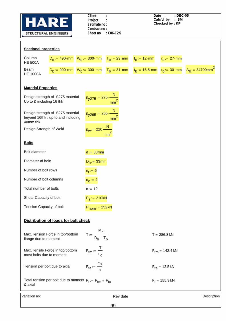
Client : Project : Estimate no : Contract no : Sheet no : C06-C2/2
Date : DEC-05Calc'd by : SMChecked by : KP
Sectional properties
Column HE 500A
Dc 490 mm⋅:= Wc 300 mm⋅:= Tc 23 mm⋅:= tc 12 mm⋅:= rc 27 mm⋅:=
Beam HE 1000A
Db 990 mm⋅:= Wb 300 mm⋅:= Tb 31 mm⋅:= tb 16.5 mm⋅:= rb 30 mm⋅:= Ab 34700mm2:=
Material Properties
Design strength of S275 materialUp to & including 16 thk
py275 275N
mm2⋅:=
Design strength of S275 materialbeyond 16thk , up to and including 40mm thk
py265 265N
mm2⋅:=
Design Strength of Weld pw 220N
mm2:=
Bolts
Bolt diameter d 30mm:=
Diameter of hole Dh 33mm:=
Number of bolt rows nr 6:=
Number of bolt columns nc 2:=
Total number of bolts n 12:=
Shear Capacity of bolt Ps 210kN:=
Tension Capacity of bolt Pnom 252kN:=
Distribution of loads for bolt check
Max.Tension Force in top/bottom flange due to moment
TMz
Db Tb−:= T 286.8 kN=
Max.Tensile Force in top/bottommost bolts due to moment
FtmTnc
:= Ftm 143.4 kN=
Tension per bolt due to axial FtaFan
:= Fta 12.5kN=
Total tension per bolt due to moment& axial
Ft Ftm Fta+:= Ft 155.9 kN=
Variation no:
Rev date Description
99

Client : Project : Estimate no : Contract no : Sheet no : C06-C2/3
Date : DEC-05Calc'd by : SMChecked by : KP
Vertical Shear per bolt FsFvn
:= Fs 75 kN=
Combined tension and shear RatioFsPs
FtPnom
+:= Ratio 0.98=
Ratio(0.98 ) < 1.4 : Therefore O.K.
Weld between beam web and end plate
7970
111.8Available length of weld Lw 2 Db 2 Tb⋅− 2 rb⋅−( )⋅:= Lw 1736 mm=
Shear per mm FLFvLw
:= FL 0.518kNmm
=
Dispersion length Ld 260.8mm:=
Tension per mm FTFtLd
:= FT 0.598kNmm
=
Resultant force per mm RFT
1.25
⎛⎜⎝
⎞
⎠
2
FL2
+:= R 0.705kNmm
=
Size of weld required sR
pw 0.7⋅:= s 4.58mm=
Adopt 6 mm CFW
Check for bending capacity of end plate
Bolt gauge g 120mm:=
Weld between beam web & end plate s 6mm:=
Moment MeFt2
g2
tb2
− 0.8s−⎛⎜⎝
⎞
⎠⋅:= Me 3.7 kN m⋅=
Thickness of end plate required treqMe 6⋅
py265 Ld⋅:= treq 17.8mm=
Adopt 20mm thick end plate
Variation no:
Rev date Description
100
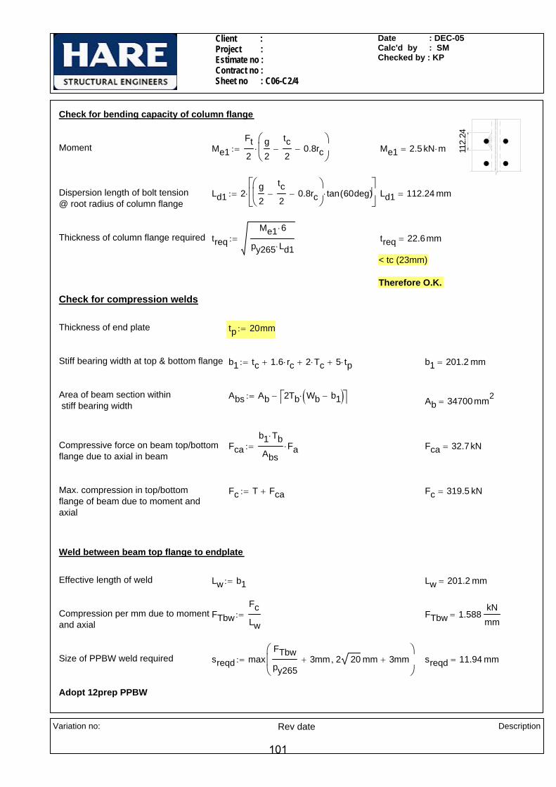
Client : Project : Estimate no : Contract no : Sheet no : C06-C2/4
Date : DEC-05Calc'd by : SMChecked by : KP
Check for bending capacity of column flange
112.
24
Moment Me1Ft2
g2
tc2
− 0.8rc−⎛⎜⎝
⎞
⎠⋅:= Me1 2.5 kN m⋅=
Dispersion length of bolt tension @ root radius of column flange
Ld1 2g2
tc2
− 0.8rc−⎛⎜⎝
⎞
⎠tan 60deg( )⋅
⎡⎢⎣
⎤⎥⎦
⋅:= Ld1 112.24 mm=
Thickness of column flange required treqMe1 6⋅
py265 Ld1⋅:= treq 22.6mm=
< tc (23mm)
Therefore O.K.
Check for compression welds
Thickness of end plate tp 20mm:=
Stiff bearing width at top & bottom flange b1 tc 1.6 rc⋅+ 2 Tc⋅+ 5 tp⋅+:= b1 201.2 mm=
Area of beam section within stiff bearing width
Abs Ab 2Tb Wb b1−( )⋅⎡⎣ ⎤⎦−:= Ab 34700 mm2=
Compressive force on beam top/bottomflange due to axial in beam
Fcab1 Tb⋅
AbsFa⋅:= Fca 32.7kN=
Max. compression in top/bottomflange of beam due to moment andaxial
Fc T Fca+:= Fc 319.5 kN=
Weld between beam top flange to endplate
Effective length of weld Lw b1:= Lw 201.2 mm=
Compression per mm due to momentand axial
FTbwFcLw
:= FTbw 1.588kNmm
=
Size of PPBW weld required sreqd maxFTbwpy265
3mm+ 2 20 mm 3mm+,⎛⎜⎜⎝
⎞
⎠:= sreqd 11.94 mm=
Adopt 12prep PPBW
Variation no:
Rev date Description
101
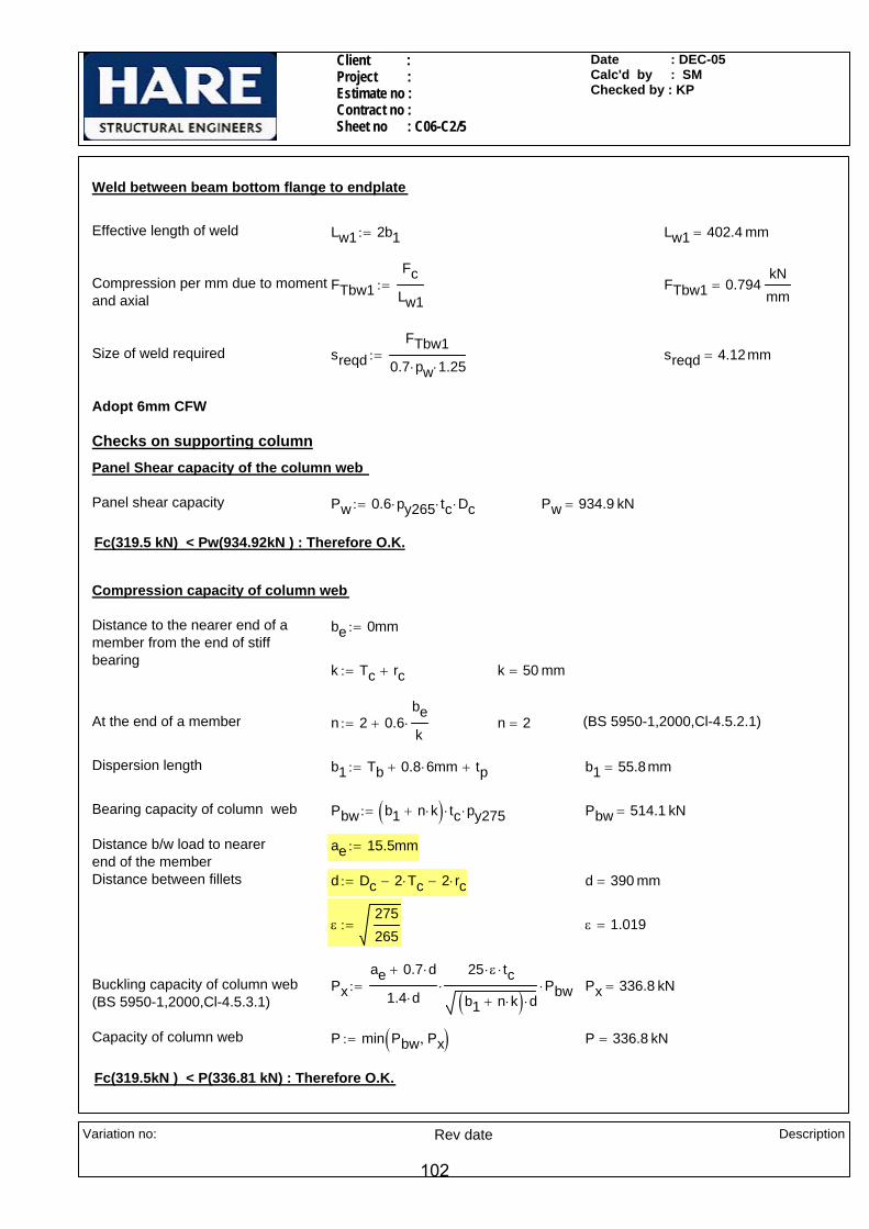
Client : Project : Estimate no : Contract no : Sheet no : C06-C2/5
Date : DEC-05Calc'd by : SMChecked by : KP
Weld between beam bottom flange to endplate
Effective length of weld Lw1 2b1:= Lw1 402.4 mm=
Compression per mm due to momentand axial
FTbw1Fc
Lw1:= FTbw1 0.794
kNmm
=
Size of weld required sreqdFTbw1
0.7 pw⋅ 1.25⋅:= sreqd 4.12mm=
Adopt 6mm CFW
Checks on supporting columnPanel Shear capacity of the column web
Panel shear capacity Pw 0.6 py265⋅ tc⋅ Dc⋅:= Pw 934.9 kN=
Fc(319.5 kN) < Pw(934.92kN ) : Therefore O.K.
Compression capacity of column web
Distance to the nearer end of a member from the end of stiffbearing
be 0mm:=
k Tc rc+:= k 50 mm=
At the end of a member n 2 0.6bek
⋅+:= n 2= (BS 5950-1,2000,Cl-4.5.2.1)
Dispersion length b1 Tb 0.8 6⋅ mm+ tp+:= b1 55.8mm=
Bearing capacity of column web Pbw b1 n k⋅+( ) tc⋅ py275⋅:= Pbw 514.1 kN=
Distance b/w load to nearer end of the member
ae 15.5mm:=
Distance between fillets d Dc 2 Tc⋅− 2 rc⋅−:= d 390 mm=
ε275265
:= ε 1.019=
Buckling capacity of column web(BS 5950-1,2000,Cl-4.5.3.1)
Pxae 0.7 d⋅+
1.4 d⋅
25 ε⋅ tc⋅
b1 n k⋅+( ) d⋅⋅ Pbw⋅:= Px 336.8 kN=
Capacity of column web P min Pbw Px,( ):= P 336.8 kN=
Fc(319.5kN ) < P(336.81 kN) : Therefore O.K.
Variation no:
Rev date Description
102

© MasterKey Joints
25125William Hare LimitedBrandlesholme House, Brandlesholme RoadBury, Manchester BL8 1JJwww.williamhare.comTel: 0161 6090000 Fax: 0161 6090409
Job RefSheetMade byDateCheckedApproved
: : C06-C3/ 001: SM: DEC-05: KP:
© Civil and Structural Computer Services Limited, 1 Circular Road, Newtownabbey, Co. Antrim BT37 0RA, Tel: 028 9036 5950 Fax: 028 9036 5102
Connection-C06-C3Beam to Column Flange Moment Connection with Haunch
6fw 6fw
11fw
pbw
6fw
6fw
507090
110
110
115
140
140
140 950
15
End-Plate 965 x 300 x 25 mm (57 kg)16 No. M20 8.8 Bolts in 22 mm holes
120
Welds grd 42 Plates S 275Beam HE 500 A 155.06 [S 275]Haunch HE 500 A 155.06 [S 275]Column HE 400 A 124.79 [S 275]Top 0 above top flange
800
Right Hand Side - Loading Case 01Basic Data
Applied Forces at Column/Right Rafter InterfaceResultant Forces M, Fv, F +450.0 kNm, +400.0 kN, +150.0 kNLoad directions Top of Joint in Tension, Rafter moving Down and in Compression.Design to BS 5950-1: 2000 and the SCI Green Book:
Joints in Steel Construction : Moment Connections: SCI-P-207/95
Basic DimensionsColumn-HE 400 A 124.79 [28] D=390, B=300, T=19, t=11, r=27.0, py=265Beam-HE 500 A 155.06 [28] D=490, B=300, T=23, t=12, r=27.0, py=265Haunch-HE 500 A 155.06 [28] D=490, B=300, T=23, t=12, r=27.0, py=265Rafter Capacities Mc, Fvc, Fc 2418.7 kN.m, 1812.6 kN, 6697.3 kN Fvc = 1812.6 kN OK
Summary of Results (Unity Ratios)Moment Capacity 515.1 kNm (for 3 rows of bolts) 0.67 OKMoment Capacity 396.0 kNm (for the 2 rows of bolts required in the tension zone) 0.87 OKShear Capacity 0.33 OKFlange Welds 1.00, 0.47 1.00 OKWeb Welds 0.73, 0.32 0.73 OKHaunch Welds 0.19, 0.59, 0.58 0.59 OKEnd of Haunch Compression Zone 0.16, 0.18 0.18 OK
103

© MasterKey Joints
25125William Hare LimitedBrandlesholme House, Brandlesholme RoadBury, Manchester BL8 1JJwww.williamhare.comTel: 0161 6090000 Fax: 0161 6090409
Job RefSheetMade byDateCheckedApproved
: : C06-C3/ 002: SM: DEC-05: KP:
© Civil and Structural Computer Services Limited, 1 Circular Road, Newtownabbey, Co. Antrim BT37 0RA, Tel: 028 9036 5950 Fax: 028 9036 5102
Right Hand Side - Loading Case 02Basic Data
Applied Forces at Column/Right Rafter InterfaceResultant Forces M, Fv, F +450.0 kNm, +400.0 kN, -150.0 kNLoad directions Top of Joint in Tension, Rafter moving Down and in Tension.Design to BS 5950-1: 2000 and the SCI Green Book:
Joints in Steel Construction : Moment Connections: SCI-P-207/95Rafter Capacities Mc, Fvc, Fc 2418.7 kN.m, 1812.6 kN, 6697.3 kN Fvc = 1812.6 kN OK
Summary of Results (Unity Ratios)Moment Capacity 555.8 kNm (for 4 rows of bolts) 1.00 OKShear Capacity 0.40 OKFlange Welds 1.00, 0.45 1.00 OKWeb Welds 0.59, 0.45 0.59 OKHaunch Welds 0.19, 0.59, 0.58 0.59 OKEnd of Haunch Compression Zone 0.16, 0.18 0.18 OK
104

© MasterKey Joints
25125William Hare LimitedBrandlesholme House, Brandlesholme RoadBury, Manchester BL8 1JJwww.williamhare.comTel: 0161 6090000 Fax: 0161 6090409
Job RefSheetMade byDateCheckedApproved
: : C06-C3/ 003: SM: DEC-05: KP:
© Civil and Structural Computer Services Limited, 1 Circular Road, Newtownabbey, Co. Antrim BT37 0RA, Tel: 028 9036 5950 Fax: 028 9036 5102
Right Hand Side - Loading Case 03Basic Data
Applied Forces at Column/Right Rafter InterfaceResultant Forces M, Fv, F -100.0 kNm, +400.0 kN, +150.0 kNLoad directions Bottom of Joint in Tension, Rafter moving Down and in Compression.Design to BS 5950-1: 2000 and the SCI Green Book:
Joints in Steel Construction : Moment Connections: SCI-P-207/95Rafter Capacities Mc, Fvc, Fc 2418.7 kN.m, 1812.6 kN, 6697.3 kN Fvc = 1812.6 kN OK
Summary of Results (Unity Ratios)Moment Capacity (for 1 rows of bolts) 0.00 OKShear Capacity 0.31 OKFlange Welds 0.00, 1.00 1.00 OKWeb Welds 0.21, 0.31 0.31 OKHaunch Welds 0.34 0.34 OK
105
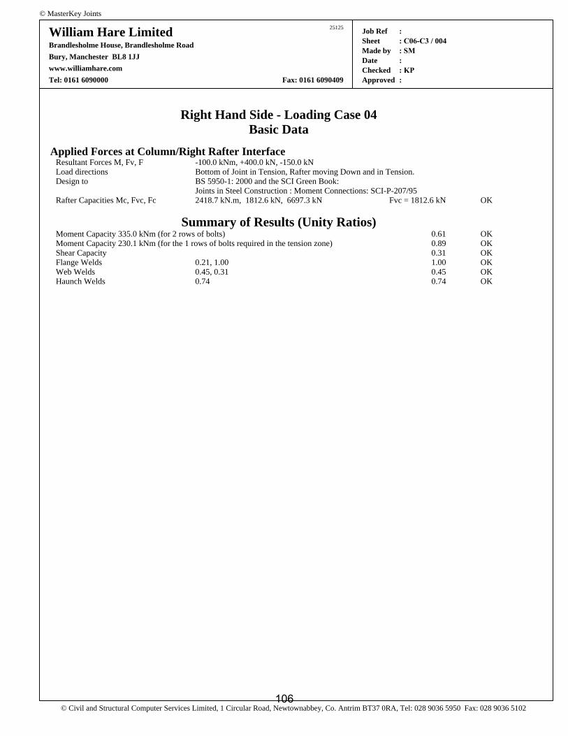
© MasterKey Joints
25125William Hare LimitedBrandlesholme House, Brandlesholme RoadBury, Manchester BL8 1JJwww.williamhare.comTel: 0161 6090000 Fax: 0161 6090409
Job RefSheetMade byDateCheckedApproved
: : C06-C3 / 004: SM: : KP:
© Civil and Structural Computer Services Limited, 1 Circular Road, Newtownabbey, Co. Antrim BT37 0RA, Tel: 028 9036 5950 Fax: 028 9036 5102
Right Hand Side - Loading Case 04Basic Data
Applied Forces at Column/Right Rafter InterfaceResultant Forces M, Fv, F -100.0 kNm, +400.0 kN, -150.0 kNLoad directions Bottom of Joint in Tension, Rafter moving Down and in Tension.Design to BS 5950-1: 2000 and the SCI Green Book:
Joints in Steel Construction : Moment Connections: SCI-P-207/95Rafter Capacities Mc, Fvc, Fc 2418.7 kN.m, 1812.6 kN, 6697.3 kN Fvc = 1812.6 kN OK
Summary of Results (Unity Ratios)Moment Capacity 335.0 kNm (for 2 rows of bolts) 0.61 OKMoment Capacity 230.1 kNm (for the 1 rows of bolts required in the tension zone) 0.89 OKShear Capacity 0.31 OKFlange Welds 0.21, 1.00 1.00 OKWeb Welds 0.45, 0.31 0.45 OKHaunch Welds 0.74 0.74 OK
106
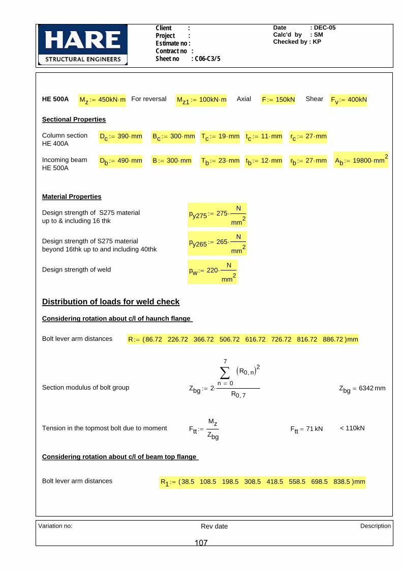
Client : Project : Estimate no : Contract no :Sheet no : C06-C3/ 5
Date : DEC-05Calc'd by : SMChecked by : KP
HE 500A Mz 450kN m⋅:= For reversal Mz1 100kN m⋅:= Axial F 150kN:= Shear Fv 400kN:=
Sectional Properties
Column sectionHE 400A
Dc 390 mm⋅:= Bc 300 mm⋅:= Tc 19 mm⋅:= tc 11 mm⋅:= rc 27 mm⋅:=
Incoming beamHE 500A
Db 490 mm⋅:= B 300 mm⋅:= Tb 23 mm⋅:= tb 12 mm⋅:= rb 27 mm⋅:= Ab 19800 mm2⋅:=
Material Properties
Design strength of S275 materialup to & including 16 thk
py275 275N
mm2⋅:=
Design strength of S275 materialbeyond 16thk up to and including 40thk
py265 265N
mm2⋅:=
Design strength of weld pw 220N
mm2⋅:=
Distribution of loads for weld check
Considering rotation about c/l of haunch flange
Bolt lever arm distances R 86.72 226.72 366.72 506.72 616.72 726.72 816.72 886.72( )mm:=
Section modulus of bolt group Zbg 20
7
n
R0 n,( )2∑=
R0 7,⋅:= Zbg 6342 mm=
Tension in the topmost bolt due to moment FttMzZbg
:= Ftt 71 kN= < 110kN
Considering rotation about c/l of beam top flange
Bolt lever arm distances R1 38.5 108.5 198.5 308.5 418.5 558.5 698.5 838.5( )mm:=
Variation no:
Rev date Description
107
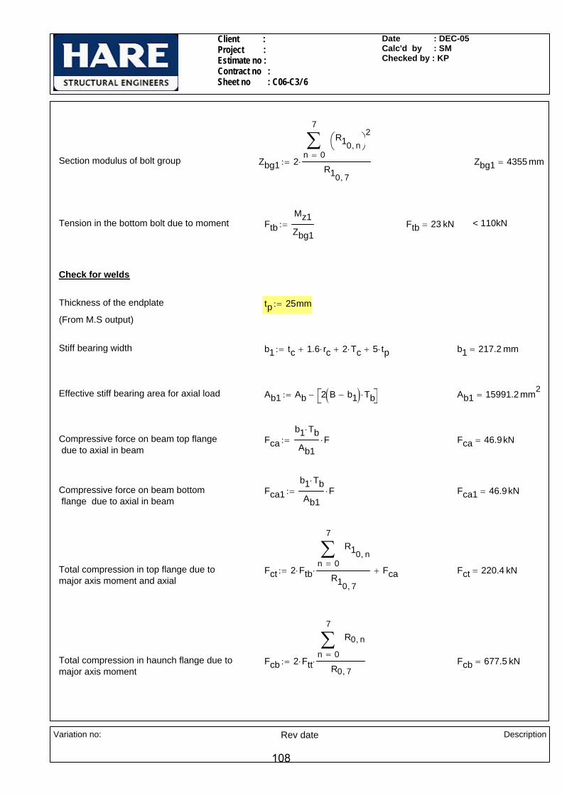
Client : Project : Estimate no : Contract no :Sheet no : C06-C3/ 6
Date : DEC-05Calc'd by : SMChecked by : KP
Section modulus of bolt group Zbg1 20
7
n
R10 n,⎛⎝
⎞⎠
2∑=
R10 7,
⋅:= Zbg1 4355 mm=
Tension in the bottom bolt due to moment FtbMz1Zbg1
:= Ftb 23 kN= < 110kN
Check for welds
Thickness of the endplate tp 25mm:=
(From M.S output)
Stiff bearing width b1 tc 1.6 rc⋅+ 2 Tc⋅+ 5 tp⋅+:= b1 217.2 mm=
Effective stiff bearing area for axial load Ab1 Ab 2 B b1−( ) Tb⋅⎡⎣ ⎤⎦−:= Ab1 15991.2 mm2=
Compressive force on beam top flange due to axial in beam
Fcab1 Tb⋅
Ab1F⋅:= Fca 46.9kN=
Compressive force on beam bottom flange due to axial in beam
Fca1b1 Tb⋅
Ab1F⋅:= Fca1 46.9kN=
Total compression in top flange due to major axis moment and axial
Fct 2 Ftb⋅0
7
n
R10 n,∑=
R10 7,
⋅ Fca+:= Fct 220.4 kN=
Total compression in haunch flange due to major axis moment
Fcb 2 Ftt⋅0
7
n
R0 n,∑=
R0 7,⋅:= Fcb 677.5 kN=
Variation no:
Rev date Description
108

Client : Project : Estimate no : Contract no :Sheet no : C06-C3/ 7
Date : DEC-05Calc'd by : SMChecked by : KP
Weld between top flange and end plate
Length available for weld Lweld b1:= Lweld 217.2 mm=
Max Compression per mm FTFct
Lweld:= FT 1.015
kNmm
=
Size of PPBW weld required s max 2 23⋅ 3+( )mmFT
py2653mm+
⎛⎜⎜⎝
⎞
⎠,
⎡⎢⎢⎣
⎤⎥⎥⎦
:= s 12.6mm=
Adopt 13mm prep PPBW
Weld between haunch flange to endplate
Haunch slope from horizontal θ 30deg:=
Max. compression CFcb
cos θ( ):= C 782.35 kN=
Stiff bearing width for weld b1 217.2 mm=
Effective length of the weld Lweld 2 b1⋅:= Lweld 434.4 mm=
Angle taken conservatively, betweenforce & throat of the welds θ1 90deg θ−( )
90deg θ−
2−:= θ1 30 deg=
K 1.251.5
1 cos θ1( )2+⋅:= K 1.16=
Compression per mm FThwC
Lweld:= FThw 1.801
kNmm
=
Size of weld required sFThw
0.7 pw⋅ K⋅:= s 10.11 mm=
Adopt 11mm CFW
Variation no:
Rev date Description
109

Client : Project : Estimate no : Contract no :Sheet no : C06-C3/ 8
Date : DEC-05Calc'd by : SMChecked by : KP
433 320
Weld between haunch web to u/s of Beam
L1 320mm:= L2 433mm:=
Compression at haunch flange C 782.35 kN=
Shear on the web portion F2 C cos θ( )⋅:= F2 677.5 kN=
Compression at beam bottom flange Fw C sin θ( )⋅:= Fw 391.2 kN=
Size of weld b/w haunch flange to u/s of beam s1 6mm:= (Assumed)
Stiff bearing area Asb L1 tb⋅ tb 1.6 rb⋅+ 5 Tb⋅+( ) 0.8⋅ s1⋅+:= Asb 4656.96 mm2=
Compressive force per mm FT
L1 tb⋅
AsbFw⋅
2 L1⋅:= FT 0.504
kNmm
=
Shear force on weld FLF2
2 L2 L1+( )⋅:= FL 0.45
kNmm
=
Resultant force on weldR
FT1.25
⎛⎜⎝
⎞
⎠
2
FL2
+:= R 0.604kNmm
=
Size of fillet weld reqd sR
0.7 pw⋅:= s 3.92mm=
Adopt 6mm CFW
Weld between Haunch flange to U/s of Beam
Compressive force per mm FTc
0.8 s1⋅ tb 1.6 rb⋅+ 5 Tb⋅+( )⋅
AsbFw⋅
tb 1.6 rb⋅+ 5 Tb⋅+:= FTc 0.403
kNmm
=
Variation no:
Rev date Description
110

Client : Project : Estimate no : Contract no :Sheet no : C06-C3/ 9
Date : DEC-05Calc'd by : SMChecked by : KP
30°
60°Angle of inclination of beam w.r.t horizontal α 0deg:=
Angle between force FTc & throat of the weld θ2 θ90 deg⋅ θ−
2+
α
2+:= θ2 60 deg=
K 1.251.5
1 cos θ2( )2+⋅:= K 1.37=
Size of fillet weld reqd sFTc
0.7 pw⋅ K⋅:= s 1.91mm=
Adopt 6mm CFW
Variation no:
Rev date Description
111

Client : Project : Estimate no : Contract no : Sheet no : C06-C4/1
Date : DEC-05Calc'd by : SSKChecked by : KP
CONNECTION C06-C4 ( Moment connection with haunch analysed using a couple force )
LOADS
Moment Mz 180kN m⋅:=
Vertical shear Fv 900kN:=
Axial force Fa 150kN:=
HE 500A
HAUNCH O/O HE 500A
800
220 x 20 THK END PLATEBOLTS @ 120 X/CRS
140
140
140
140
140
110
HE
500
A
950
12mm PREP.PPBW
NOTES:-
All bolts are M24. Grade 8.8.
All welds are 6mm CFW,UNO
Variation no:
Rev date Description
112
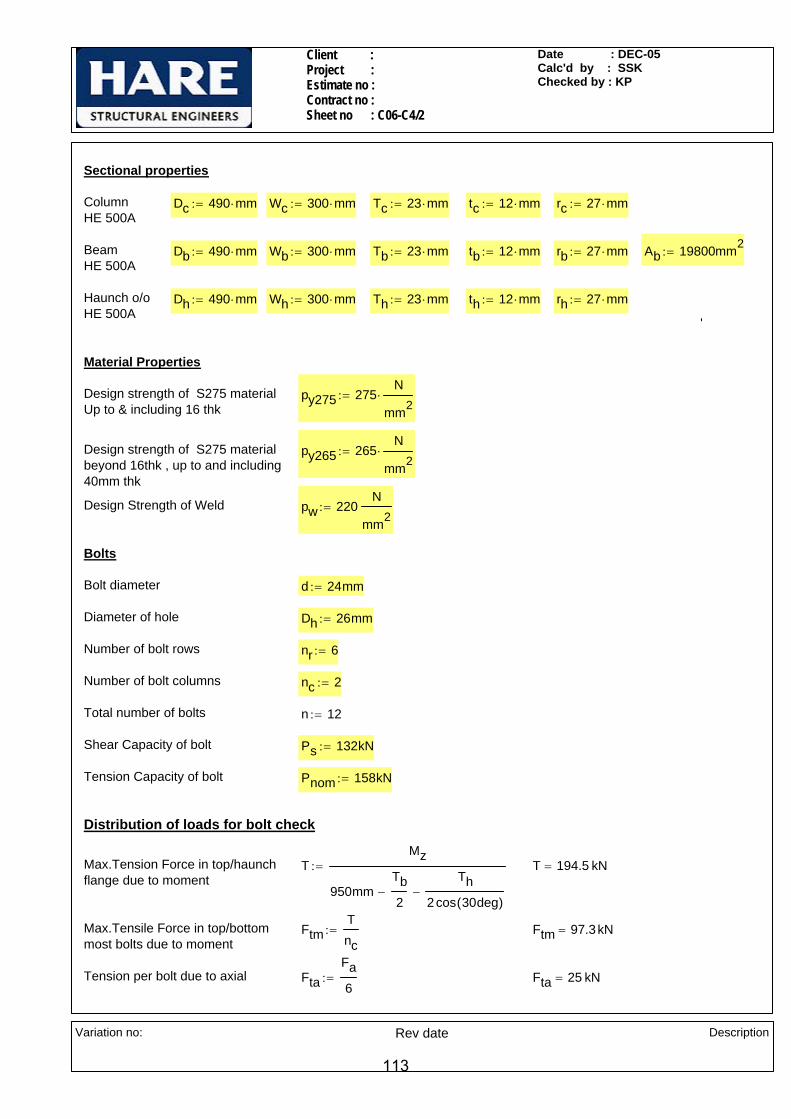
Client : Project : Estimate no : Contract no : Sheet no : C06-C4/2
Date : DEC-05Calc'd by : SSKChecked by : KP
Sectional properties
Column HE 500A
Dc 490 mm⋅:= Wc 300 mm⋅:= Tc 23 mm⋅:= tc 12 mm⋅:= rc 27 mm⋅:=
Beam HE 500A
Db 490 mm⋅:= Wb 300 mm⋅:= Tb 23 mm⋅:= tb 12 mm⋅:= rb 27 mm⋅:= Ab 19800mm2:=
Haunch o/oHE 500A
Dh 490 mm⋅:= Wh 300 mm⋅:= Th 23 mm⋅:= th 12 mm⋅:= rh 27 mm⋅:=
'
Material Properties
Design strength of S275 materialUp to & including 16 thk
py275 275N
mm2⋅:=
Design strength of S275 materialbeyond 16thk , up to and including 40mm thk
py265 265N
mm2⋅:=
Design Strength of Weld pw 220N
mm2:=
Bolts
Bolt diameter d 24mm:=
Diameter of hole Dh 26mm:=
Number of bolt rows nr 6:=
Number of bolt columns nc 2:=
Total number of bolts n 12:=
Shear Capacity of bolt Ps 132kN:=
Tension Capacity of bolt Pnom 158kN:=
Distribution of loads for bolt check
Max.Tension Force in top/haunch flange due to moment
TMz
950mmTb2
−Th
2cos 30deg( )−
:= T 194.5 kN=
Max.Tensile Force in top/bottommost bolts due to moment
FtmTnc
:= Ftm 97.3kN=
Tension per bolt due to axial FtaFa6
:= Fta 25 kN=
Variation no:
Rev date Description
113
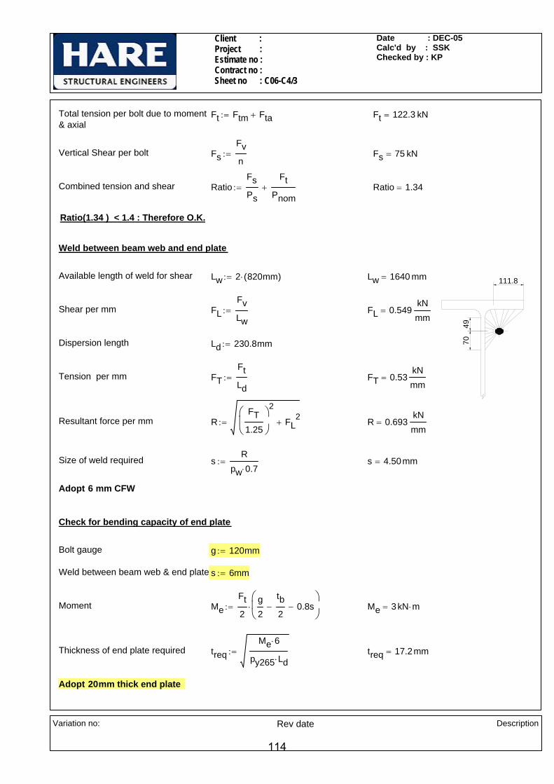
Client : Project : Estimate no : Contract no : Sheet no : C06-C4/3
Date : DEC-05Calc'd by : SSKChecked by : KP
Total tension per bolt due to moment& axial
Ft Ftm Fta+:= Ft 122.3 kN=
Vertical Shear per bolt FsFvn
:= Fs 75 kN=
Combined tension and shear RatioFsPs
FtPnom
+:= Ratio 1.34=
Ratio(1.34 ) < 1.4 : Therefore O.K.
Weld between beam web and end plate
70
111.8
49
Available length of weld for shear Lw 2 820mm( )⋅:= Lw 1640 mm=
Shear per mm FLFvLw
:= FL 0.549kNmm
=
Dispersion length Ld 230.8mm:=
Tension per mm FTFtLd
:= FT 0.53kNmm
=
Resultant force per mm RFT
1.25
⎛⎜⎝
⎞
⎠
2
FL2
+:= R 0.693kNmm
=
Size of weld required sR
pw 0.7⋅:= s 4.50mm=
Adopt 6 mm CFW
Check for bending capacity of end plate
Bolt gauge g 120mm:=
Weld between beam web & end plate s 6mm:=
Moment MeFt2
g2
tb2
− 0.8s−⎛⎜⎝
⎞
⎠⋅:= Me 3 kN m⋅=
Thickness of end plate required treqMe 6⋅
py265 Ld⋅:= treq 17.2mm=
Adopt 20mm thick end plate
Variation no:
Rev date Description
114
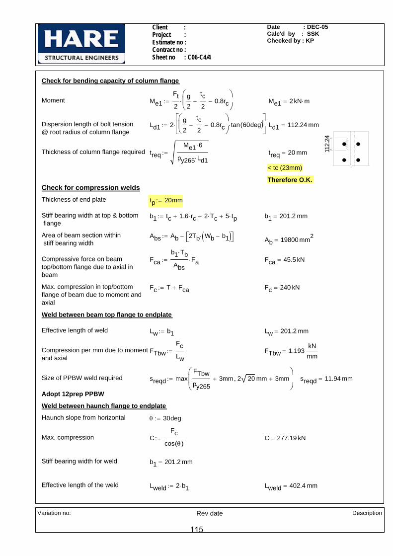
Client : Project : Estimate no : Contract no : Sheet no : C06-C4/4
Date : DEC-05Calc'd by : SSKChecked by : KP
Check for bending capacity of column flange
Moment Me1Ft2
g2
tc2
− 0.8rc−⎛⎜⎝
⎞
⎠⋅:= Me1 2 kN m⋅=
Dispersion length of bolt tension @ root radius of column flange
Ld1 2g2
tc2
− 0.8rc−⎛⎜⎝
⎞
⎠tan 60deg( )⋅
⎡⎢⎣
⎤⎥⎦
⋅:= Ld1 112.24 mm=
112.
24
Thickness of column flange required treqMe1 6⋅
py265 Ld1⋅:= treq 20 mm=
< tc (23mm)
Therefore O.K.Check for compression weldsThickness of end plate tp 20mm:=
Stiff bearing width at top & bottom flange
b1 tc 1.6 rc⋅+ 2 Tc⋅+ 5 tp⋅+:= b1 201.2 mm=
Area of beam section within stiff bearing width
Abs Ab 2Tb Wb b1−( )⋅⎡⎣ ⎤⎦−:= Ab 19800 mm2=
Compressive force on beam top/bottom flange due to axial inbeam
Fcab1 Tb⋅
AbsFa⋅:= Fca 45.5kN=
Max. compression in top/bottomflange of beam due to moment andaxial
Fc T Fca+:= Fc 240 kN=
Weld between beam top flange to endplate
Effective length of weld Lw b1:= Lw 201.2 mm=
Compression per mm due to momentand axial
FTbwFcLw
:= FTbw 1.193kNmm
=
Size of PPBW weld required sreqd maxFTbwpy265
3mm+ 2 20 mm 3mm+,⎛⎜⎜⎝
⎞
⎠:= sreqd 11.94 mm=
Adopt 12prep PPBW
Weld between haunch flange to endplate
Haunch slope from horizontal θ 30deg:=
Max. compression CFc
cos θ( ):= C 277.19 kN=
Stiff bearing width for weld b1 201.2 mm=
Effective length of the weld Lweld 2 b1⋅:= Lweld 402.4 mm=
Variation no:
Rev date Description
115

Client : Project : Estimate no : Contract no : Sheet no : C06-C4/5
Date : DEC-05Calc'd by : SSKChecked by : KP
Angle taken conservatively, betweenforce & throat of the welds
θ1 90deg θ−( )90deg θ−
2−:= θ1 30 deg=
K 1.251.5
1 cos θ1( )2+⋅:= K 1.16=
Compression per mm FThwC
Lweld:= FThw 0.689
kNmm
=
Size of weld required sFThw
0.7 pw⋅ K⋅:= s 3.87mm=
Adopt 6mm CFW
431.1 315.6Weld between haunch web to u/s of Beam
L1 315.6mm:= L2 431.1mm:=
Compression at haunch flange C 277.19 kN=
Shear on the web portion F2 C cos θ( )⋅:= F2 240 kN=
Compression at beam bottom flange Fw C sin θ( )⋅:= Fw 138.6 kN=
Size of weld b/w haunch flange & u/s of beam s1 6mm:= (Assumed)
Stiff bearing area Asb L1 tb⋅ tb 1.6 rb⋅+ 5 Tb⋅+( ) 0.8⋅ s1⋅+:= Asb 4604.16 mm2=
Compressive force per mm FT
L1 tb⋅
AsbFw⋅
2 L1⋅:= FT 0.181
kNmm
=
Shear force on weld FLF2
2 L2 L1+( )⋅:= FL 0.161
kNmm
=
Resultant force on weldR
FT1.25
⎛⎜⎝
⎞
⎠
2
FL2
+:= R 0.216kNmm
=
Size of fillet weld reqd sR
0.7 pw⋅:= s 1.4 mm=
Adopt 6mm CFW
Variation no:
Rev date Description
116

Client : Project : Estimate no : Contract no : Sheet no : C06-C4/6
Date : DEC-05Calc'd by : SSKChecked by : KP
Weld between Haunch flange to U/s of Beam
Compressive force per mm FTc
0.8 s1⋅ tb 1.6 rb⋅+ 5 Tb⋅+( )⋅
AsbFw⋅
tb 1.6 rb⋅+ 5 Tb⋅+:= FTc 0.144
kNmm
=
30°
60°
Angle of inclination of beam w.r.t horizontal α 0deg:=
Angle between force & throat of the weld θ2 θ90 deg⋅ θ−
2+
α
2+:= θ2 60 deg=
K 1.251.5
1 cos θ2( )2+⋅:= K 1.37=
Size of fillet weld reqd sFTc
0.7 pw⋅ K⋅:= s 0.69mm=
431.1 315.6
158
863 A
A
Adopt 6mm CFW
Compression capacity of haunch
Dispersion length dp 158mm:=
Length of haunch Lh 863mm:=
Area of haunch @Section A-A A Wh Th⋅ dp th⋅+:= A 8796 mm2=
C.g of T-section about X-X axis Cx
Wh Th2
⋅
2dp th⋅ Th
dp2
+⎛⎜⎝
⎞
⎠⋅+
Wh Th⋅ dp th⋅+:= Cx 31.01 mm=
Moment of inertia about XX axis,
IxxWh Th
3⋅
12Wh Th⋅ Cx
Th2
−⎛⎜⎝
⎞
⎠
2
⋅+dp
3 th⋅
12+ dp th⋅ Cx Th−
dp2
−⎛⎜⎝
⎞
⎠
2
⋅+:= Ixx 16429947.5 mm4=
Moment of inertia IyyWh
3 Th⋅
12
dp th3
⋅
12+:= Iyy 51772752 mm4
=
Min. Radius of gyration rymin Iyy Ixx,( )
A:= ry 43.2mm=
Variation no:
Rev date Description
117
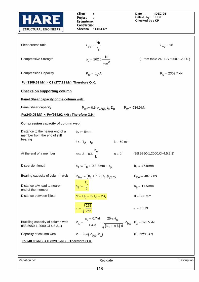
Client : Project : Estimate no : Contract no : Sheet no : C06-C4/7
Date : DEC-05Calc'd by : SSKChecked by : KP
Slenderness ratio λyyLhry
:= λyy 20=
Compressive Strength pc 262.6N
mm2= ( From table 24 , BS 5950-1-2000 )
Compression Capacity Pc pc A⋅:= Pc 2309.7 kN=
Pc (2309.69 kN) > C1 (277.19 kN), Therefore O.K.
Checks on supporting column
Panel Shear capacity of the column web
Panel shear capacity Pw 0.6 py265⋅ tc⋅ Dc⋅:= Pw 934.9 kN=
Fc(240.05 kN) < Pw(934.92 kN) : Therefore O.K.
Compression capacity of column web
Distance to the nearer end of a member from the end of stiffbearing
be 0mm:=
k Tc rc+:= k 50 mm=
At the end of a member n 2 0.6bek
⋅+:= n 2= (BS 5950-1,2000,Cl-4.5.2.1)
Dispersion length b1 Tb 0.8 6⋅ mm+ tp+:= b1 47.8mm=
Bearing capacity of column web Pbw b1 n k⋅+( ) tc⋅ py275⋅:= Pbw 487.7 kN=
Distance b/w load to nearer end of the member
aeTc2
:= ae 11.5mm=
Distance between fillets d Dc 2 Tc⋅− 2 rc⋅−:= d 390 mm=
ε275265
:= ε 1.019=
Buckling capacity of column web(BS 5950-1,2000,Cl-4.5.3.1)
Pxae 0.7 d⋅+
1.4 d⋅
25 ε⋅ tc⋅
b1 n k⋅+( ) d⋅⋅ Pbw⋅:= Px 323.5 kN=
Capacity of column web P min Pbw Px,( ):= P 323.5 kN=
Fc(240.05kN ) < P (323.5kN ) : Therefore O.K.
Variation no:
Rev date Description
118
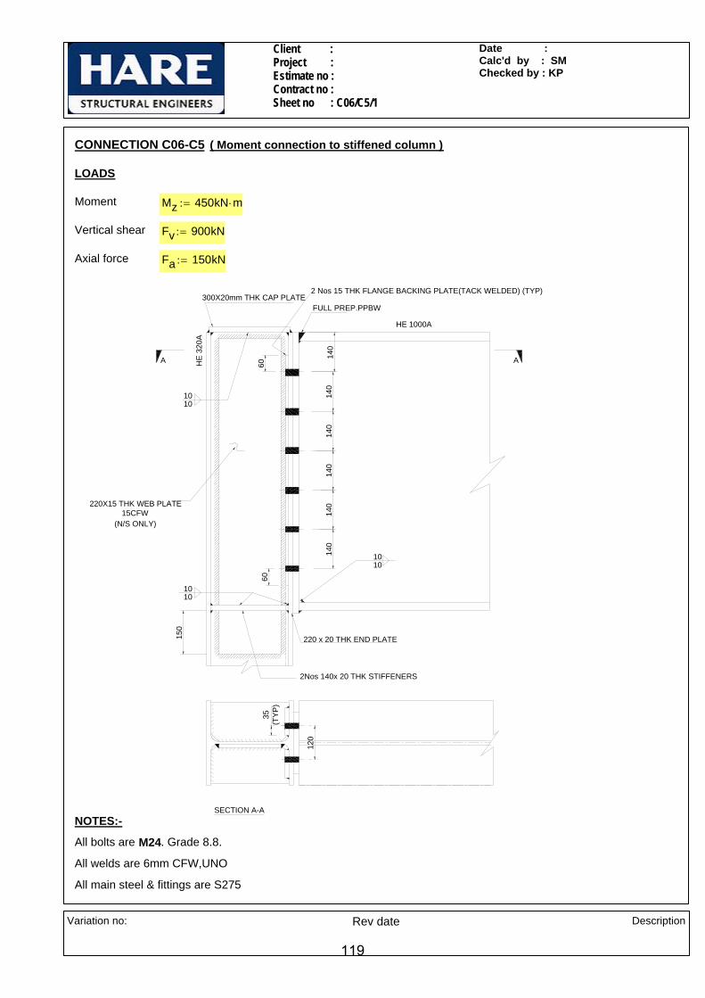
Client : Project : Estimate no : Contract no : Sheet no : C06/C5/1
Date : Calc'd by : SMChecked by : KP
220 x 20 THK END PLATE
FULL PREP.PPBW
HE 1000A
HE
320A
2 Nos 15 THK FLANGE BACKING PLATE(TACK WELDED) (TYP)
220X15 THK WEB PLATE15CFW
(N/S ONLY)
150
6060
1010
1010
SECTION A-A
A A
35(T
YP)
120
140
140
140
140
140
140
300X20mm THK CAP PLATE
1010
2Nos 140x 20 THK STIFFENERS
CONNECTION C06-C5 ( Moment connection to stiffened column )
LOADS
Moment Mz 450kN m⋅:=
Vertical shear Fv 900kN:=
Axial force Fa 150kN:=
NOTES:-
All bolts are M24. Grade 8.8.
All welds are 6mm CFW,UNO
All main steel & fittings are S275
Variation no:
Rev date Description
119

Client : Project : Estimate no : Contract no : Sheet no : C06/C5/2
Date : Calc'd by : SMChecked by : KP
Sectional properties
Column HE 320A
Dc 310 mm⋅:= Wc 300 mm⋅:= Tc 15.5 mm⋅:= tc 9mm:= dc 225mm:= rc 27 mm⋅:=
Beam HE 1000A
Db 990 mm⋅:= Wb 300 mm⋅:= Tb 31 mm⋅:= tb 16.5 mm⋅:= rb 30 mm⋅:= Ab 34700mm2:=
Material Properties
Design strength of S275 materialUp to & including 16 thk
py275 275N
mm2⋅:=
Design strength of S275 materialbeyond 16thk , up to and including 40mm thk
py265 265N
mm2⋅:=
Design Strength of Weld pw 220N
mm2:=
Bolts
Bolt diameter d 24mm:=
Diameter of hole Dh 26mm:=
Number of bolt rows nr 6:=
Number of bolt columns nc 2:=
Total number of bolts n 12:=
Bolt pitch p 140mm:=
Bolt gauge g 120mm:=
Shear Capacity of bolt Ps 132kN:=
Tension Capacity of bolt Pnom 158kN:=
Distribution of loads for bolt check
Taking rotation about centre of beam bottom flange
R 134.5 274.5 414.5 554.5 694.5 834.5( )mm:=
Section modulus of bolt group Zp
2
0
5
n
R0 n,( )2∑=
⋅⎡⎢⎢⎣
⎤⎥⎥⎦
R0 5,:= Zp 4198 mm=
Max.Tensile Force in topmost boltdue to moment
FttMzZp
:= Ftt 107.2 kN=
Variation no:
Rev date Description
120

Client : Project : Estimate no : Contract no : Sheet no : C06/C5/3
Date : Calc'd by : SMChecked by : KP
For reversal load
Taking rotation about centre of beam top flange
R1 124.5 264.5 404.5 544.5 684.5 824.5( )mm:=
Section modulus of bolt group Zn
2
0
5
n
R10 n,⎛⎝
⎞⎠
2∑=
⋅⎡⎢⎢⎣
⎤⎥⎥⎦
R10 5,
:= Zn 4108.9 mm=
Max.Tensile Force in bottommostbolt due to moment
FtbMzZn
:= Ftb 109.5 kN=
Max.Tensile Force on Singlebolt due to moment
Ftm max Ftt Ftb,( ):= Ftm 109.5 kN= < 158 kN
Tension per bolt due to axial FtaFan
:= Fta 12.5kN=
Total tension per bolt due to moment& axial
Ft Ftm Fta+:= Ft 122 kN=
Vertical Shear per bolt FsFvn
:= Fs 75 kN=
Combined tension and shear RatioFsPs
FtPnom
+:= Ratio 1.34=
Ratio(1.34 ) < 1.4 : Therefore O.K.
Weld between beam web and end plate
Available length of weld Lw 2 Db 2 Tb⋅− 2 rb⋅−( )⋅:= Lw 1736 mm=
Shear per mm FLFvLw
:= FL 0.518kNmm
=
Tension in 5th bolt row from top Ft5Ftb
R10 5,
R10 4,⋅ Fta+:= Ft5 103.4 kN=
Dispersion length Ld 2g2
tb2
−⎛⎜⎝
⎞
⎠⋅ tan 60 deg⋅( )⋅:= Ld 179.3 mm=
Tension per mm FTFt5Ld
:= FT 0.577kNmm
=
Variation no:
Rev date Description
121

Client : Project : Estimate no : Contract no : Sheet no : C06/C5/4
Date : Calc'd by : SMChecked by : KP
Resultant force per mm RFT
1.25
⎛⎜⎝
⎞
⎠
2
FL2
+:= R 0.694kNmm
=
Size of weld required sR
pw 0.7⋅:= s 4.507 mm=
Adopt 6 mm CFW
Check for bending capacity of end plate
Bolt gauge g 120mm:=
Weld between beam web & end plate s 6mm:=
Moment MeFt2
g2
tb2
− 0.8s−⎛⎜⎝
⎞
⎠⋅:= Me 2.9 kN m⋅=
Thickness of end plate required treqMe 6⋅
py265 Ld⋅:= treq 19 mm=
Adopt 20mm thick end plate
Thickness of end plate tp 20mm:=
Stiffbearing width at top/bottom flangeb1 Wb:= b1 300 mm=
Area of beam section within stiff bearing width
Abs Ab 2Tb Wb b1−( )⋅⎡⎣ ⎤⎦−:= Ab 34700 mm2=
Compressive force on top/bottomflange of beam due to axial in beam
Fcab1 Tb⋅
AbsFa⋅:= Fca 40.2kN=
Maxcompression in top/bottom flangeof beam due to moment and axial(worst case)
Fct
2 Ftb⋅
0
5
n
R10 n,∑=
⎛⎜⎜⎝
⎞
⎠
⋅
R10 5,
Fca+:= Fct 796.5 kN=
Max. compression in top/bottomflange of beam due to moment andaxial
Fc Fct Fca+:= Fc 836.7 kN=
Checks on supporting columnCheck for bending capacity of column flange
Moment Me1Ft2
g2
tc2
− rc−⎛⎜⎝
⎞
⎠⋅:= Me1 1.7 kN m⋅=
98.7
3
Dispersion length Ld1 2g2
tc2
− rc−⎛⎜⎝
⎞
⎠⋅ tan 60 deg⋅( )⋅:= Ld1 98.73 mm=
Thickness of end plate required treqMe1 6⋅
py265 Ld1⋅:= treq 19.97 mm=
Tc(19.97mm ) < treq(15.5mm ) : Therefore FAILS
Variation no:
Rev date Description
122

Client : Project : Estimate no : Contract no : Sheet no : C06/C5/5
Date : Calc'd by : SMChecked by : KP
Thickness of flange plate required Tfp treq2 Tc
2−:= Tfp 12.6mm=
Provide 15 thk flange backing plate
Panel Shear capacity of the column web
Panel shear capacity Pw 0.6 py265⋅ tc⋅ Dc⋅:= Pw 443.6 kN=
Pw(443.61kN ) < Fc(836.73kN ) : Therefore FAILS
Thickness pf web plate twp 15mm:=
Width of web plate bs 220mm:=
Panel shear capacity with 10 thksupplymentary web plate
Pw 0.6 py265⋅ tc⋅ Dc⋅( ) 0.6 py265⋅ bs⋅ twp⋅( )+:= Pw 968.3 kN=
Fc(836.73 kN) < Pw(968.31 kN) : Therefore O.K.
Hence adopt 15 thk web plate
Compression capacity of column web
Distance to the nearer end of a member from the end of stiffbearing
be 0mm:=
k Tc rc+:= k 42.5mm=
At the end of a member n 2 0.6bek
⋅+:= n 2= (BS 5950-1,2000,Cl-4.5.2.1)
Dispersion length b1 Tb 0.8 6⋅ mm+ tp+:= b1 55.8mm=
Bearing capacity of column web Pbw b1 n k⋅+( ) tc⋅ py275⋅:= Pbw 348.5 kN=
Distance b/w load to nearer end of the member
aeTb2
:= ae 15.5mm=
Distance between fillets d Dc 2 Tc⋅− 2 rc⋅−:= d 225 mm=
ε275265
:= ε 1.019=
Buckling capacity of column web(BS 5950-1,2000,Cl-4.5.3.1)
Pxae 0.7 d⋅+
1.4 d⋅
25 ε⋅ tc⋅
b1 n k⋅+( ) d⋅⋅ Pbw⋅:= Px 246.5 kN=
Variation no:
Rev date Description
123

Client : Project : Estimate no : Contract no : Sheet no : C06/C5/6
Date : Calc'd by : SMChecked by : KP
Capacity of column web P min Pbw Px,( ):= P 246.5 kN=
P(246.46 kN)< Fc(836.73kN ) : Therefore FAILS
Provide 300 x 20 thk cap plate & 2Nos 140x20 thk stiffeners in column web in line with bottom flange
Check for column web buckling with cap plate
Thickness of cap plate ts 20mm:=
Width of cap plate Wcp 300mm:=
Length of column web resisting compression buckling
Lo 15 tc×:= Lo 135 mm=
Moment of inertia of the section
( 15t
c )
y
y
ts
tc
Wcp
IyyWcp ts
3×
12
Lo tc3
×
12+
⎛⎜⎜⎝
⎞
⎠:=
Iyy 208201.3 mm4=
A Wcp ts× Lo tc⋅+( ):=
A 7215 mm2=
Min radius of gyration ryyIyyA
:= ryy 5.4 mm=
λ0.7 dc( )⋅
ryy:=
λ 29.32=
pc 262.4N
mm2= From Table-24,Strut Curve c, B.S-5950-1(2000)
Buckling capacity Px A pc⋅:= Px 1893.4 kN=
Fc(836.73kN ) < Px(1893.4kN ) : Therefore cap plate thickness is O.K.
Check for compression weldsThickness of end plate tp 20mm:=
Stiffbearing width at top/bottom flange b1 220mm:= b1 220 mm=
Area of beam section within stiff bearing width
Abs Ab 2Tb Wb b1−( )⋅⎡⎣ ⎤⎦−:= Ab 34700 mm2=
Compressive force on top/bottomflange of beam due to axial in beam
Fcab1 Tb⋅
AbsFa⋅:= Fca 34.4kN=
Variation no:
Rev date Description
124

Client : Project : Estimate no : Contract no : Sheet no : C06/C5/7
Date : Calc'd by : SMChecked by : KP
Maxcompression in top flangeof beam due to moment and axial(worst case)
Fct
2 Ftb⋅
0
5
n
R10 n,∑=
⎛⎜⎜⎝
⎞
⎠
⋅
R10 5,
Fca+:= Fct 790.7 kN=
Maxcompression in bottom flangeof beam due to moment and axial(worst case)
Fcb
2 Ftt⋅
0
5
n
R0 n,∑=
⎛⎜⎜⎝
⎞
⎠
⋅
R0 5,Fca+:= Fcb 781.3 kN=
Weld between beam top flange to endplate
Effective length of weld for PPBW Lw b1:= Lw 220 mm=
Capacity of full prep.PPBW Fctp min Tc tp,( ) 3mm−( ) b1⋅ py265⋅:= Fctp 728.8 kN=
Compression acting on fillet weld Fctf Fct Fctp−:= Fctf 62 kN=
Effective length of weld for CFW Lwf b1 tb− 2 rb⋅−:= Lwf 143.5 mm=
Compression per mm on fillet welddue to moment and axial
FTbwFctfLwf
:= FTbw 0.432kNmm
=
Size of CFW required sreqdFTbw
0.7 pw⋅ 1.25⋅:= sreqd 2.24mm=
Adopt full prep., PPBW @ top side & 6mm CFW @ bottom side.
Weld between beam bottom flange to endplate
Effective length of weld Lw1 2b1:= Lw1 440 mm=
Compression per mm due to momentand axial
FTbw1FcbLw1
:= FTbw1 1.776kNmm
=
Size of weld required sreqdFTbw1
0.7 pw⋅ 1.25⋅:= sreqd 9.22mm=
Adopt 10mm CFW
Weld between cap plate and column flange
Compression resisted by stiffener Fcs Fc P−:= Fcs 590.3 kN=
Length of weld available Lweld 2 Wcp⋅ 2tc−:= Lweld 582 mm=
Variation no:
Rev date Description
125
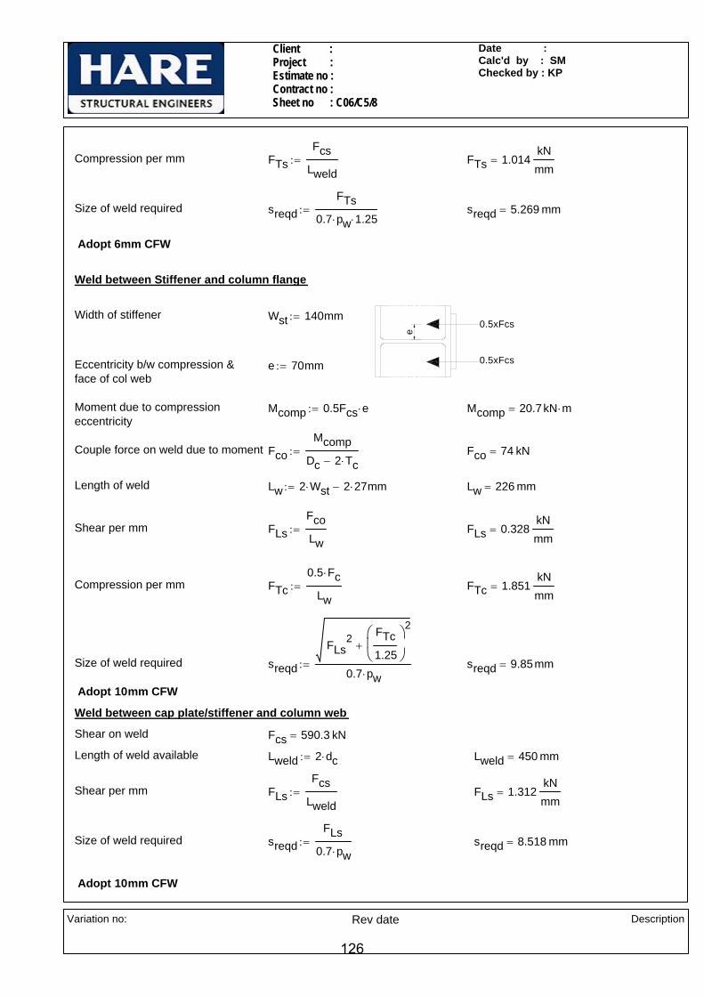
Client : Project : Estimate no : Contract no : Sheet no : C06/C5/8
Date : Calc'd by : SMChecked by : KP
Compression per mm FTsFcs
Lweld:= FTs 1.014
kNmm
=
Size of weld required sreqdFTs
0.7 pw⋅ 1.25⋅:= sreqd 5.269 mm=
Adopt 6mm CFW
Weld between Stiffener and column flange
e
0.5xFcs
0.5xFcs
Width of stiffener Wst 140mm:=
Eccentricity b/w compression & face of col web
e 70mm:=
Moment due to compression eccentricity
Mcomp 0.5Fcs e⋅:= Mcomp 20.7kN m⋅=
Couple force on weld due to moment FcoMcomp
Dc 2 Tc⋅−:= Fco 74 kN=
Length of weld Lw 2 Wst⋅ 2 27⋅ mm−:= Lw 226 mm=
Shear per mm FLsFcoLw
:= FLs 0.328kNmm
=
Compression per mm FTc0.5 Fc⋅
Lw:= FTc 1.851
kNmm
=
Size of weld required sreqd
FLs2 FTc
1.25
⎛⎜⎝
⎞
⎠
2
+
0.7 pw⋅:= sreqd 9.85mm=
Adopt 10mm CFW
Weld between cap plate/stiffener and column web
Shear on weld Fcs 590.3 kN=
Length of weld available Lweld 2 dc⋅:= Lweld 450 mm=
Shear per mm FLsFcs
Lweld:= FLs 1.312
kNmm
=
Size of weld required sreqdFLs
0.7 pw⋅:= sreqd 8.518 mm=
Adopt 10mm CFW
Variation no:
Rev date Description
126

Client : Project : Estimate no : Contract no : Sheet no : C06-C6/1
Date : DEC-05Calc'd by : SMChecked by : KP
2 Nos 100X25 THK FLANGE BACKING PLATES(TACK WELDED) (TYP)
2Nos 140 x 20 THK STIFFENERS
13mm PREP.PPBW
220 x 25 THK END PLATE
SECTION A-A
A70
7070
70
(N/S ONLY)
10 THK WEB PLATE10CFW
20mm THK CAP PLATE
140
140
140
HE 3
20A
140
140
140
A
HE 1000A
120
150
42(T
YP)
CONNECTION C06-C6 ( Moment connection to stiffened column analysed using a couple force )
LOADS
Moment Mz 450kN m⋅:=
Vertical shear Fv 900kN:=
Axial force Fa 150kN:=
NOTES:-
All bolts are M30. Grade 8.8.
All welds are 6mm CFW,UNO
All main steel & fittings are S275.
Variation no:
Rev date Description
127
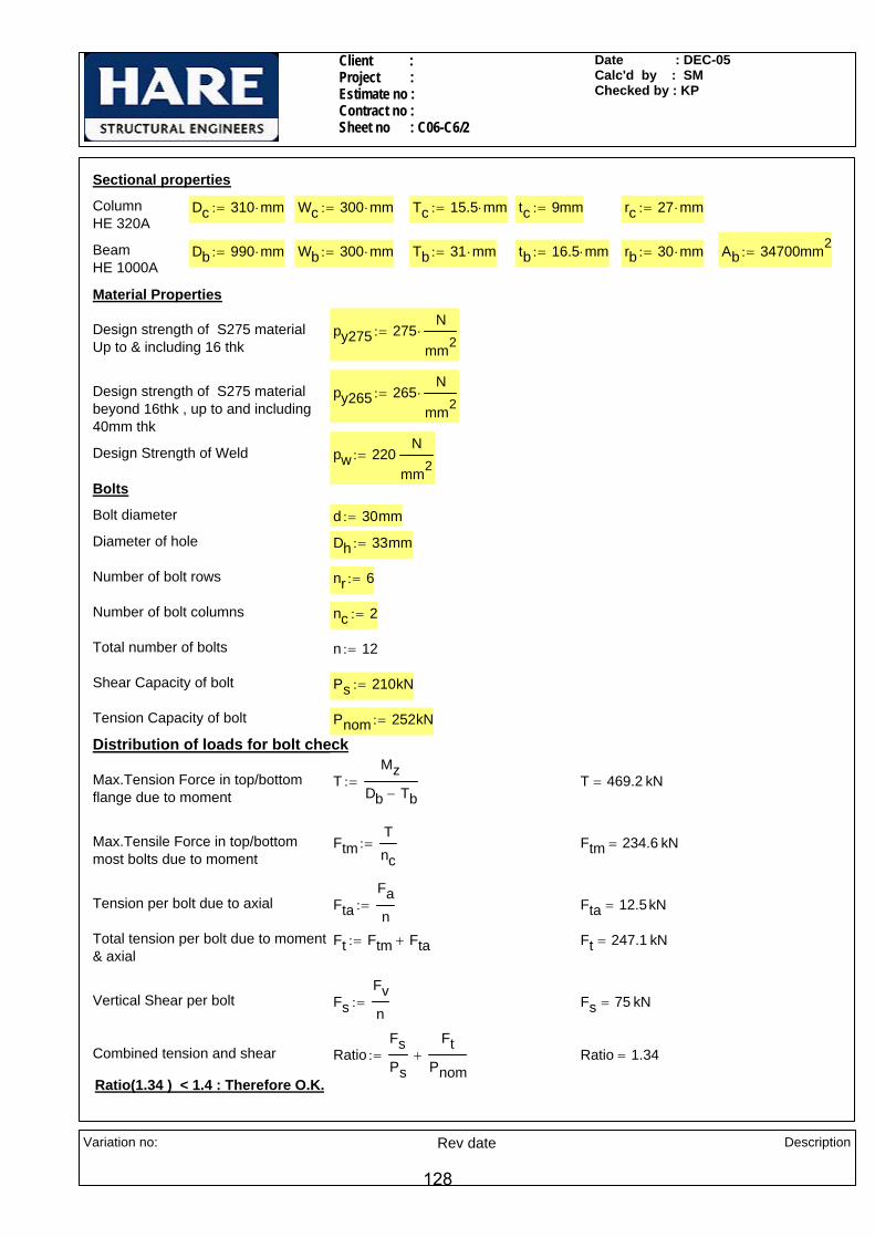
Client : Project : Estimate no : Contract no : Sheet no : C06-C6/2
Date : DEC-05Calc'd by : SMChecked by : KP
Sectional properties
Column HE 320A
Dc 310 mm⋅:= Wc 300 mm⋅:= Tc 15.5 mm⋅:= tc 9mm:= rc 27 mm⋅:=
Beam HE 1000A
Db 990 mm⋅:= Wb 300 mm⋅:= Tb 31 mm⋅:= tb 16.5 mm⋅:= rb 30 mm⋅:= Ab 34700mm2:=
Material Properties
Design strength of S275 materialUp to & including 16 thk
py275 275N
mm2⋅:=
Design strength of S275 materialbeyond 16thk , up to and including 40mm thk
py265 265N
mm2⋅:=
Design Strength of Weld pw 220N
mm2:=
Bolts
Bolt diameter d 30mm:=
Diameter of hole Dh 33mm:=
Number of bolt rows nr 6:=
Number of bolt columns nc 2:=
Total number of bolts n 12:=
Shear Capacity of bolt Ps 210kN:=
Tension Capacity of bolt Pnom 252kN:=
Distribution of loads for bolt check
Max.Tension Force in top/bottom flange due to moment
TMz
Db Tb−:= T 469.2 kN=
Max.Tensile Force in top/bottommost bolts due to moment
FtmTnc
:= Ftm 234.6 kN=
Tension per bolt due to axial FtaFan
:= Fta 12.5kN=
Total tension per bolt due to moment& axial
Ft Ftm Fta+:= Ft 247.1 kN=
Vertical Shear per bolt FsFvn
:= Fs 75 kN=
Combined tension and shear RatioFsPs
FtPnom
+:= Ratio 1.34=
Ratio(1.34 ) < 1.4 : Therefore O.K.
Variation no:
Rev date Description
128
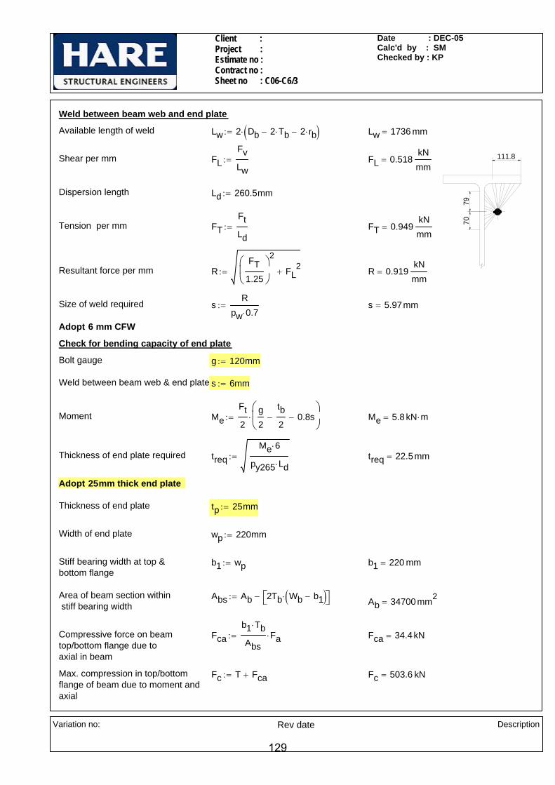
Client : Project : Estimate no : Contract no : Sheet no : C06-C6/3
Date : DEC-05Calc'd by : SMChecked by : KP
Weld between beam web and end plate
Available length of weld Lw 2 Db 2 Tb⋅− 2 rb⋅−( )⋅:= Lw 1736 mm=
7970
111.8Shear per mm FLFvLw
:= FL 0.518kNmm
=
Dispersion length Ld 260.5mm:=
Tension per mm FTFtLd
:= FT 0.949kNmm
=
Resultant force per mm RFT
1.25
⎛⎜⎝
⎞
⎠
2
FL2
+:= R 0.919kNmm
=
Size of weld required sR
pw 0.7⋅:= s 5.97mm=
Adopt 6 mm CFW
Check for bending capacity of end plate
Bolt gauge g 120mm:=
Weld between beam web & end plate s 6mm:=
Moment MeFt2
g2
tb2
− 0.8s−⎛⎜⎝
⎞
⎠⋅:= Me 5.8 kN m⋅=
Thickness of end plate required treqMe 6⋅
py265 Ld⋅:= treq 22.5mm=
Adopt 25mm thick end plate
Thickness of end plate tp 25mm:=
Width of end plate wp 220mm:=
Stiff bearing width at top & bottom flange
b1 wp:= b1 220 mm=
Area of beam section within stiff bearing width
Abs Ab 2Tb Wb b1−( )⋅⎡⎣ ⎤⎦−:= Ab 34700 mm2=
Compressive force on beam top/bottom flange due to axial in beam
Fcab1 Tb⋅
AbsFa⋅:= Fca 34.4kN=
Max. compression in top/bottomflange of beam due to moment andaxial
Fc T Fca+:= Fc 503.6 kN=
Variation no:
Rev date Description
129
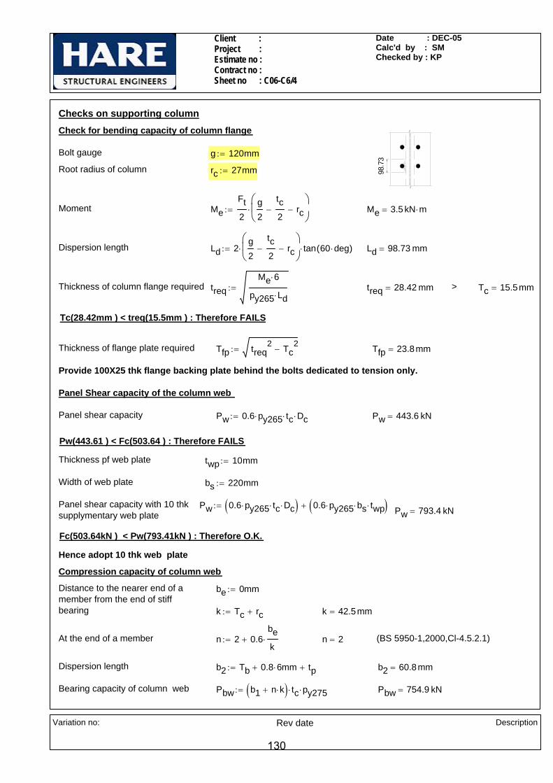
Client : Project : Estimate no : Contract no : Sheet no : C06-C6/4
Date : DEC-05Calc'd by : SMChecked by : KP
Checks on supporting column
98.7
3
Check for bending capacity of column flange
Bolt gauge g 120mm:=
Root radius of column rc 27mm:=
Moment MeFt2
g2
tc2
− rc−⎛⎜⎝
⎞
⎠⋅:= Me 3.5 kN m⋅=
Dispersion length Ld 2g2
tc2
− rc−⎛⎜⎝
⎞
⎠⋅ tan 60 deg⋅( )⋅:= Ld 98.73 mm=
Thickness of column flange required treqMe 6⋅
py265 Ld⋅:= treq 28.42 mm= > Tc 15.5mm=
Tc(28.42mm ) < treq(15.5mm ) : Therefore FAILS
Thickness of flange plate required Tfp treq2 Tc
2−:= Tfp 23.8mm=
Provide 100X25 thk flange backing plate behind the bolts dedicated to tension only.
Panel Shear capacity of the column web
Panel shear capacity Pw 0.6 py265⋅ tc⋅ Dc⋅:= Pw 443.6 kN=
Pw(443.61 ) < Fc(503.64 ) : Therefore FAILS
Thickness pf web plate twp 10mm:=
Width of web plate bs 220mm:=
Panel shear capacity with 10 thksupplymentary web plate
Pw 0.6 py265⋅ tc⋅ Dc⋅( ) 0.6 py265⋅ bs⋅ twp⋅( )+:= Pw 793.4 kN=
Fc(503.64kN ) < Pw(793.41kN ) : Therefore O.K.
Hence adopt 10 thk web plate
Compression capacity of column web
Distance to the nearer end of a member from the end of stiffbearing
be 0mm:=
k Tc rc+:= k 42.5mm=
At the end of a member n 2 0.6bek
⋅+:= n 2= (BS 5950-1,2000,Cl-4.5.2.1)
Dispersion length b2 Tb 0.8 6⋅ mm+ tp+:= b2 60.8mm=
Bearing capacity of column web Pbw b1 n k⋅+( ) tc⋅ py275⋅:= Pbw 754.9 kN=
Variation no:
Rev date Description
130

Client : Project : Estimate no : Contract no : Sheet no : C06-C6/5
Date : DEC-05Calc'd by : SMChecked by : KP
Distance b/w load to nearer end of the member
aeTb2
:= ae 15.5mm=
Distance between fillets d Dc 2 Tc⋅− 2 rc⋅−:= d 225 mm=
ε275265
:= ε 1.019=
Buckling capacity of column web(BS 5950-1,2000,Cl-4.5.3.1)
Pxae 0.7 d⋅+
1.4 d⋅
25 ε⋅ tc⋅
b1 n k⋅+( ) d⋅⋅ Pbw⋅:= Px 362.7 kN=
Capacity of column web P min Pbw Px,( ):= P 362.74 kN=
P(362.74 kN)< Fc(503.64kN ) : Therefore FAILS
Provide 300 x 20 thk cap plate & 2Nos 140x20 thk stiffeners in column web in line with bottom flange.
Check for column web buckling with cap plate
Thickness of cap plate ts 20mm:=
Width of cap plate Wcp 300mm:=
Length of column web resisting compression buckling
Lo 15 tc×:= Lo 135 mm=
Moment of inertia of the section
( 15t
c )
y
y
ts
tc
WcpIyy
Wcp ts3
×
12
Lo tc3
×
12+
⎛⎜⎜⎝
⎞
⎠:=
Iyy 208201.3 mm4=
A Wcp ts× Lo tc⋅+( ):=
A 7215 mm2=
Min radius of gyration ryyIyyA
:= ryy 5.4 mm=
λ0.7 Dc 2 Tc⋅− 2 rc⋅−( )⋅
ryy:= λ 29.32=
pc 262.4N
mm2= From Table-24,Strut Curve c, B.S-5950-1(2000)
Buckling capacity Px A pc⋅:= Px 1893.4 kN=
Fc(503.64kN ) < Px(1893.4kN ) : Therefore cap plate thickness is O.K.
Variation no:
Rev date Description
131

Client : Project : Estimate no : Contract no : Sheet no : C06-C6/6
Date : DEC-05Calc'd by : SMChecked by : KP
Check for compression weldsThickness of end plate tp 25 mm=
Weld between beam top flange to endplate
Effective length of weld for PPBW Lw b1:= Lw 220 mm=
Max Compression per mm FTFcLw
:= FT 2.289kNmm
=
Size of PPBW weld required s max 2 25⋅ 3+( )mmFT
py2653mm+
⎛⎜⎜⎝
⎞
⎠,
⎡⎢⎢⎣
⎤⎥⎥⎦
:= s 13 mm=
Adopt 13 prep., PPBW.
Weld between beam bottom flange to endplate
Effective length of weld Lw1 2b1:= Lw1 440 mm=
Compression per mm due to momentand axial
FTbw1Fc
Lw1:= FTbw1 1.145
kNmm
=
Size of weld required sreqdFTbw1
0.7 pw⋅ 1.25⋅:= sreqd 5.95mm=
Adopt 6mm CFW
Weld between cap plate and column flange
Compression to be resisted by stiffener
Fcs Fc P−:= Fcs 140.9 kN=
Length of weld available Lweld 2 Wcp⋅ 2tc−:= Lweld 582 mm=
Compression per mm FTsFcs
Lweld:= FTs 0.242
kNmm
=
Size of weld required sreqdFTs
0.7 pw⋅ 1.25⋅:= sreqd 1.26mm=
e
0.5xFcs
0.5xFcs
Adopt 6mm CFW
Weld between Stiffener and column flange
Width of stiffener Wst 140mm:=
Eccentricity b/w compression & face of col web
e 70mm:=
Moment due to compression eccentricity
Mcomp 0.5Fcs e⋅:= Mcomp 4.9 kN m⋅=
Variation no:
Rev date Description
132
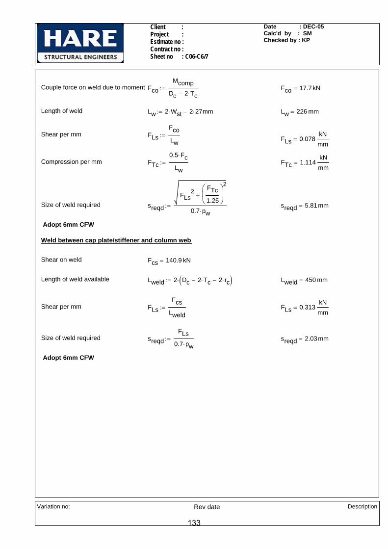
Client : Project : Estimate no : Contract no : Sheet no : C06-C6/7
Date : DEC-05Calc'd by : SMChecked by : KP
Couple force on weld due to moment FcoMcomp
Dc 2 Tc⋅−:= Fco 17.7kN=
Length of weld Lw 2 Wst⋅ 2 27⋅ mm−:= Lw 226 mm=
Shear per mm FLsFcoLw
:= FLs 0.078kNmm
=
Compression per mm FTc0.5 Fc⋅
Lw:= FTc 1.114
kNmm
=
Size of weld required sreqd
FLs2 FTc
1.25
⎛⎜⎝
⎞
⎠
2
+
0.7 pw⋅:= sreqd 5.81mm=
Adopt 6mm CFW
Weld between cap plate/stiffener and column web
Shear on weld Fcs 140.9 kN=
Length of weld available Lweld 2 Dc 2 Tc⋅− 2 rc⋅−( )⋅:= Lweld 450 mm=
Shear per mm FLsFcs
Lweld:= FLs 0.313
kNmm
=
Size of weld required sreqdFLs
0.7 pw⋅:= sreqd 2.03mm=
Adopt 6mm CFW
Variation no:
Rev date Description
133

Client : Project : Estimate no : Contract no :Sheet no : C06-C7 /1
Date : DEC-05Calc'd by : MSChecked by : SM
Connection - C06-C7 (Moment connection with haunch to stiffened column )
IPE 450 Mz 440kN m⋅:= My 5kN m⋅:= Axial Ax 370kN:= Shear Sv 120kN:= Sh 15kN:=
1100
7011
011
011
011
590
9014
0
570
2Nos 15 THK STIFFENERSSNIPES 15X15
(TYP)
(TYP)
15 THK WEB PLATE 15 CFW ALLROUND (N/S ONLY)
780
(TYP
)
280
(TYP
)
15 THK CAP PLATE
15 15
FLANGES ONLY(TYP)
(TYP
)55
220x30THK (TYP)END PLATE
IPE 450 IPE 450
HAUNCH O/O IPE 450
(TYP)
1616
FLANGES ONLY(TYP)
FLANGE BACKING PLATE90x10 THK (TYP)
A A
SECTION A-A
HE45
0A
35(T
YP)
88(TYP)
Notes All bolts are M24 Grade 8.8.
All welds are 6mm CFW UNO
All main steel & fittings are S275
Variation no:
Rev date Description
134

© MasterKey Joints - C:\Documents and Settings\MSELVAN\Desktop\C06-7NEW
25125William Hare LimitedBrandlesholme House, Brandlesholme RoadBury, Manchester BL8 1JJwww.williamhare.comTel: 0161 6090000 Fax: 0161 6090409
Job RefSheetMade byDateCheckedApproved
: : C06-C7/ 2: MS: DEC-05 / Ver. 2004.10: SM:
© Civil and Structural Computer Services Limited, 1 Circular Road, Newtownabbey, Co. Antrim BT37 0RA, Tel: 028 9036 5950 Fax: 028 9036 5102
Connection-C06-C7Double Beam to Column Flange End-Plated Connection
70110110110
50140
9090
115
15
780
90
End-Plate 885 x 220 x 30 mm (46 kg)16 No. M24 8.8 Bolts in 27 mm holesEnd-Plate WeldsTop Flange 15 FWHaunch Flange 16 FWWeb 6 FWHaunch WeldsHaunch Web to Beam Flange 8 FWEnd of Haunch to Beam Flange 6 FW
140
15 tk 6 fw
15 tk 6 fw
Welds grd 42 Plates S 275Shear Stiffener 15 tk x 1400 ln 15 fwL. Beam IPE 450 77.57 [S 275]L. Haunch IPE 450 77.57 [S 275]Column HE 450 A 139.75 [S 275]Top 15 above top left flange
820
140140
70110110110
501409090115
15
780
90
End-Plate 885 x 220 x 30 mm (46 kg)16 No. M24 8.8 Bolts in 26 mm holesEnd-Plate WeldsTop Flange 15 FWHaunch Flange 16 FWWeb 6 FWHaunch WeldsHaunch Web to Beam Flange 8 FWEnd of Haunch to Beam Flange 6 FW
140
15 tk 6 fw
15 tk 6 fw
R. Beam IPE 450 77.57 [S 275]R. Haunch IPE 450 77.57 [S 275]
820
140140
Left Hand Side - Loading Case 01Basic Data
Applied Forces at Column/Left Rafter InterfaceResultant Forces M, Fv, F +440.0 kNm, +120.0 kN, +370.0 kNLoad directions Top of Joint in Tension, Rafter moving Down and in Compression.Design to BS 5950-1: 2000 and the SCI Green Book:
Joints in Steel Construction : Moment Connections: SCI-P-207/95
Left Side Basic DimensionsColumn-HE 450 A 139.75 [28] D=440, B=300, T=21, t=11.5, r=27.0, py=265Beam-IPE 450 77.57 [28] D=450, B=190, T=14.6, t=9.4, r=21.0, py=275Haunch-IPE 450 77.57 [28] D=450, B=190, T=14.6, t=9.4, r=21.0, py=275Rafter Capacities Mc, Fvc, Fc 986.8 kN.m, 1209.8 kN, 3570.6 kN Mc = 986.8 kN.m OK
Summary of Results (Unity Ratios)Moment Capacity 614.9 kNm (for 5 rows of bolts) 0.41 OKMoment Capacity 406.7 kNm (for the 2 rows of bolts required in the tension zone) 0.63 OKShear Capacity 0.07 OKColumn Tension Stiffener at row 0 0.05, 0.20, 0.03, 0.10, 0.35 0.35 OKBeam Tension Stiffener at row 4 0.00, 0.23, 0.14, 0.20, 0.41 0.41 OKFlange Welds 0.47, 0.68 0.68 OKWeb Welds 0.68, 0.14 0.68 OKHaunch Welds 0.28, 0.99, 0.88 0.99 OKColumn Compression stiff Web Weld 0.61 0.61 OKEnd of Haunch Compression Zone 0.31, 0.36 0.36 OK
Right Hand Side - Loading Case 01Basic Data
Applied Forces at Column/Right Rafter InterfaceResultant Forces M, Fv, F +440.0 kNm, +120.0 kN, +370.0 kNLoad directions Top of Joint in Tension, Rafter moving Down and in Compression.Design to BS 5950-1: 2000 and the SCI Green Book:
Joints in Steel Construction : Moment Connections: SCI-P-207/95
135
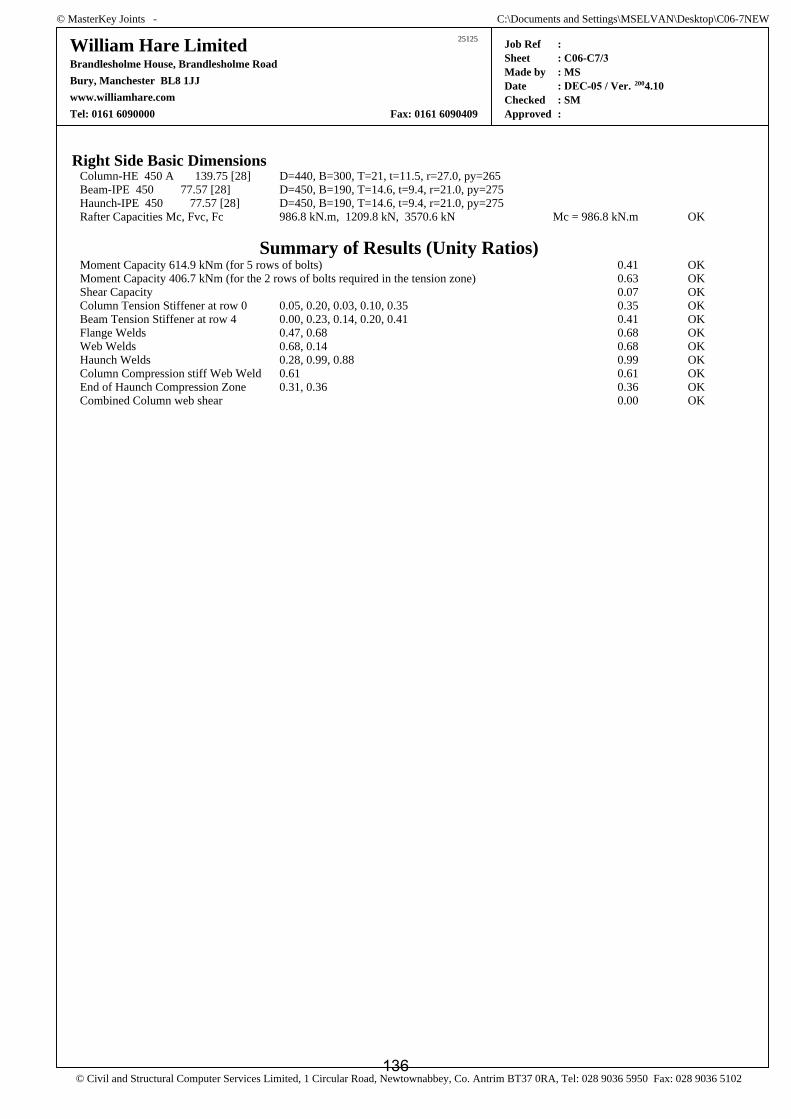
© MasterKey Joints - C:\Documents and Settings\MSELVAN\Desktop\C06-7NEW
25125William Hare LimitedBrandlesholme House, Brandlesholme RoadBury, Manchester BL8 1JJwww.williamhare.comTel: 0161 6090000 Fax: 0161 6090409
Job RefSheetMade byDateCheckedApproved
: : C06-C7/3: MS: DEC-05 / Ver. 2004.10: SM:
© Civil and Structural Computer Services Limited, 1 Circular Road, Newtownabbey, Co. Antrim BT37 0RA, Tel: 028 9036 5950 Fax: 028 9036 5102
Right Side Basic DimensionsColumn-HE 450 A 139.75 [28] D=440, B=300, T=21, t=11.5, r=27.0, py=265Beam-IPE 450 77.57 [28] D=450, B=190, T=14.6, t=9.4, r=21.0, py=275Haunch-IPE 450 77.57 [28] D=450, B=190, T=14.6, t=9.4, r=21.0, py=275Rafter Capacities Mc, Fvc, Fc 986.8 kN.m, 1209.8 kN, 3570.6 kN Mc = 986.8 kN.m OK
Summary of Results (Unity Ratios)Moment Capacity 614.9 kNm (for 5 rows of bolts) 0.41 OKMoment Capacity 406.7 kNm (for the 2 rows of bolts required in the tension zone) 0.63 OKShear Capacity 0.07 OKColumn Tension Stiffener at row 0 0.05, 0.20, 0.03, 0.10, 0.35 0.35 OKBeam Tension Stiffener at row 4 0.00, 0.23, 0.14, 0.20, 0.41 0.41 OKFlange Welds 0.47, 0.68 0.68 OKWeb Welds 0.68, 0.14 0.68 OKHaunch Welds 0.28, 0.99, 0.88 0.99 OKColumn Compression stiff Web Weld 0.61 0.61 OKEnd of Haunch Compression Zone 0.31, 0.36 0.36 OKCombined Column web shear 0.00 OK
136

© MasterKey Joints - C:\Documents and Settings\MSELVAN\Desktop\C06-7NEW
25125William Hare LimitedBrandlesholme House, Brandlesholme RoadBury, Manchester BL8 1JJwww.williamhare.comTel: 0161 6090000 Fax: 0161 6090409
Job RefSheetMade byDateCheckedApproved
: : C06-C7/4: MS: DEC-05, 2006 / Ver. 2004.10: SM:
© Civil and Structural Computer Services Limited, 1 Circular Road, Newtownabbey, Co. Antrim BT37 0RA, Tel: 028 9036 5950 Fax: 028 9036 5102
Left Hand Side - Loading Case 02Basic Data
Applied Forces at Column/Left Rafter InterfaceResultant Forces M, Fv, F +440.0 kNm, +120.0 kN, -370.0 kNLoad directions Top of Joint in Tension, Rafter moving Down and in Tension.Design to BS 5950-1: 2000 and the SCI Green Book:
Joints in Steel Construction : Moment Connections: SCI-P-207/95Rafter Capacities Mc, Fvc, Fc 986.8 kN.m, 1209.8 kN, 3570.6 kN Mc = 986.8 kN.m OK
Summary of Results (Unity Ratios)Moment Capacity 710.4 kNm (for 7 rows of bolts) 0.90 OKMoment Capacity 648.9 kNm (for the 4 rows of bolts required in the tension zone) 0.99 OKShear Capacity 0.08 OKColumn Tension Stiffener at row 0 0.05, 0.20, 0.03, 0.10, 0.35 0.35 OKBeam Tension Stiffener at row 4 0.00, 0.28, 0.17, 0.24, 0.49 0.49 OKFlange Welds 0.75, 0.68 0.75 OKWeb Welds 0.69, 0.27 0.69 OKHaunch Welds 0.28, 0.99, 0.88 0.99 OKColumn Compression stiff Web Weld 0.58 0.58 OKEnd of Haunch Compression Zone 0.31, 0.36 0.36 OK
Right Hand Side - Loading Case 02Basic Data
Applied Forces at Column/Right Rafter InterfaceResultant Forces M, Fv, F +440.0 kNm, +120.0 kN, -370.0 kNLoad directions Top of Joint in Tension, Rafter moving Down and in Tension.Design to BS 5950-1: 2000 and the SCI Green Book:
Joints in Steel Construction : Moment Connections: SCI-P-207/95Rafter Capacities Mc, Fvc, Fc 986.8 kN.m, 1209.8 kN, 3570.6 kN Mc = 986.8 kN.m OK
Summary of Results (Unity Ratios)Moment Capacity 710.4 kNm (for 7 rows of bolts) 0.90 OKMoment Capacity 648.9 kNm (for the 4 rows of bolts required in the tension zone) 0.99 OKShear Capacity 0.08 OKColumn Tension Stiffener at row 0 0.05, 0.20, 0.03, 0.10, 0.35 0.35 OKBeam Tension Stiffener at row 4 0.00, 0.28, 0.17, 0.24, 0.49 0.49 OKFlange Welds 0.75, 0.68 0.75 OKWeb Welds 0.69, 0.27 0.69 OKHaunch Welds 0.28, 0.99, 0.88 0.99 OKColumn Compression stiff Web Weld 0.58 0.58 OKEnd of Haunch Compression Zone 0.31, 0.36 0.36 OKCombined Column web shear 0.00 OK
137

© MasterKey Joints - C:\Documents and Settings\MSELVAN\Desktop\C06-7NEW
25125William Hare LimitedBrandlesholme House, Brandlesholme RoadBury, Manchester BL8 1JJwww.williamhare.comTel: 0161 6090000 Fax: 0161 6090409
Job RefSheetMade byDateCheckedApproved
: : C06-C7/5: MS: DEC-05 / Ver. 2004.10: SM:
© Civil and Structural Computer Services Limited, 1 Circular Road, Newtownabbey, Co. Antrim BT37 0RA, Tel: 028 9036 5950 Fax: 028 9036 5102
Left Hand Side - Loading Case 03Basic Data
Applied Forces at Column/Left Rafter InterfaceResultant Forces M, Fv, F -440.0 kNm, +120.0 kN, +370.0 kNLoad directions Bottom of Joint in Tension, Rafter moving Down and in Compression.Design to BS 5950-1: 2000 and the SCI Green Book:
Joints in Steel Construction : Moment Connections: SCI-P-207/95Rafter Capacities Mc, Fvc, Fc 986.8 kN.m, 1209.8 kN, 3570.6 kN Mc = 986.8 kN.m OK
Summary of Results (Unity Ratios)Moment Capacity 687.9 kNm (for 4 rows of bolts) 0.36 OKMoment Capacity 296.7 kNm (for the 1 rows of bolts required in the tension zone) 0.84 OKShear Capacity 0.06 OKColumn Tension Stiffener at row 1 0.00, 0.31, 0.04, 0.15, 0.55 0.55 OKBeam Tension Stiffener at row 4 0.00, 0.07, 0.04, 0.06, 0.12 0.12 OKFlange Welds 0.35, 0.73 0.73 OKWeb Welds 0.00, 0.09 0.09 OKHaunch Welds 0.28, 0.99, 0.88 0.99 OKColumn Compression stiff Web Weld 0.54 0.54 OK
Right Hand Side - Loading Case 03Basic Data
Applied Forces at Column/Right Rafter InterfaceResultant Forces M, Fv, F -440.0 kNm, +120.0 kN, +370.0 kNLoad directions Bottom of Joint in Tension, Rafter moving Down and in Compression.Design to BS 5950-1: 2000 and the SCI Green Book:
Joints in Steel Construction : Moment Connections: SCI-P-207/95Rafter Capacities Mc, Fvc, Fc 986.8 kN.m, 1209.8 kN, 3570.6 kN Mc = 986.8 kN.m OK
Summary of Results (Unity Ratios)Moment Capacity 687.9 kNm (for 4 rows of bolts) 0.36 OKMoment Capacity 296.7 kNm (for the 1 rows of bolts required in the tension zone) 0.84 OKShear Capacity 0.06 OKColumn Tension Stiffener at row 1 0.00, 0.31, 0.04, 0.15, 0.55 0.55 OKBeam Tension Stiffener at row 4 0.00, 0.07, 0.04, 0.06, 0.12 0.12 OKFlange Welds 0.35, 0.73 0.73 OKWeb Welds 0.00, 0.09 0.09 OKHaunch Welds 0.28, 0.99, 0.88 0.99 OKColumn Compression stiff Web Weld 0.54 0.54 OKCombined Column web shear 0.00 OK
138
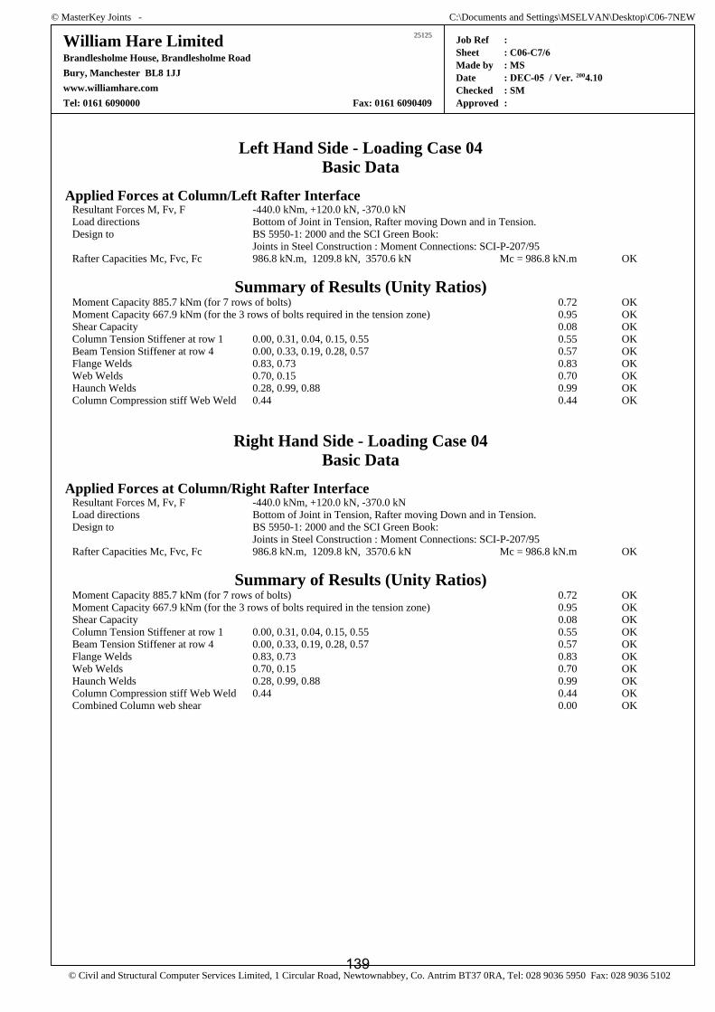
© MasterKey Joints - C:\Documents and Settings\MSELVAN\Desktop\C06-7NEW
25125William Hare LimitedBrandlesholme House, Brandlesholme RoadBury, Manchester BL8 1JJwww.williamhare.comTel: 0161 6090000 Fax: 0161 6090409
Job RefSheetMade byDateCheckedApproved
: : C06-C7/6: MS: DEC-05 / Ver. 2004.10: SM:
© Civil and Structural Computer Services Limited, 1 Circular Road, Newtownabbey, Co. Antrim BT37 0RA, Tel: 028 9036 5950 Fax: 028 9036 5102
Left Hand Side - Loading Case 04Basic Data
Applied Forces at Column/Left Rafter InterfaceResultant Forces M, Fv, F -440.0 kNm, +120.0 kN, -370.0 kNLoad directions Bottom of Joint in Tension, Rafter moving Down and in Tension.Design to BS 5950-1: 2000 and the SCI Green Book:
Joints in Steel Construction : Moment Connections: SCI-P-207/95Rafter Capacities Mc, Fvc, Fc 986.8 kN.m, 1209.8 kN, 3570.6 kN Mc = 986.8 kN.m OK
Summary of Results (Unity Ratios)Moment Capacity 885.7 kNm (for 7 rows of bolts) 0.72 OKMoment Capacity 667.9 kNm (for the 3 rows of bolts required in the tension zone) 0.95 OKShear Capacity 0.08 OKColumn Tension Stiffener at row 1 0.00, 0.31, 0.04, 0.15, 0.55 0.55 OKBeam Tension Stiffener at row 4 0.00, 0.33, 0.19, 0.28, 0.57 0.57 OKFlange Welds 0.83, 0.73 0.83 OKWeb Welds 0.70, 0.15 0.70 OKHaunch Welds 0.28, 0.99, 0.88 0.99 OKColumn Compression stiff Web Weld 0.44 0.44 OK
Right Hand Side - Loading Case 04Basic Data
Applied Forces at Column/Right Rafter InterfaceResultant Forces M, Fv, F -440.0 kNm, +120.0 kN, -370.0 kNLoad directions Bottom of Joint in Tension, Rafter moving Down and in Tension.Design to BS 5950-1: 2000 and the SCI Green Book:
Joints in Steel Construction : Moment Connections: SCI-P-207/95Rafter Capacities Mc, Fvc, Fc 986.8 kN.m, 1209.8 kN, 3570.6 kN Mc = 986.8 kN.m OK
Summary of Results (Unity Ratios)Moment Capacity 885.7 kNm (for 7 rows of bolts) 0.72 OKMoment Capacity 667.9 kNm (for the 3 rows of bolts required in the tension zone) 0.95 OKShear Capacity 0.08 OKColumn Tension Stiffener at row 1 0.00, 0.31, 0.04, 0.15, 0.55 0.55 OKBeam Tension Stiffener at row 4 0.00, 0.33, 0.19, 0.28, 0.57 0.57 OKFlange Welds 0.83, 0.73 0.83 OKWeb Welds 0.70, 0.15 0.70 OKHaunch Welds 0.28, 0.99, 0.88 0.99 OKColumn Compression stiff Web Weld 0.44 0.44 OKCombined Column web shear 0.00 OK
139

© MasterKey Joints - C:\Documents and Settings\MSELVAN\Desktop\C06-7NEW
25125William Hare LimitedBrandlesholme House, Brandlesholme RoadBury, Manchester BL8 1JJwww.williamhare.comTel: 0161 6090000 Fax: 0161 6090409
Job RefSheetMade byDateCheckedApproved
: : C06-C7/ 7: MS: DEC-05 / Ver. 2004.10: SM:
© Civil and Structural Computer Services Limited, 1 Circular Road, Newtownabbey, Co. Antrim BT37 0RA, Tel: 028 9036 5950 Fax: 028 9036 5102
Left Hand Side - Loading Case 05Basic Data
Applied Forces at Column/Left Rafter InterfaceResultant Forces M, Fv, F +440.0 kNm, +120.0 kN, +370.0 kNLoad directions Top of Joint in Tension, Rafter moving Down and in Compression.Design to BS 5950-1: 2000 and the SCI Green Book:
Joints in Steel Construction : Moment Connections: SCI-P-207/95Rafter Capacities Mc, Fvc, Fc 986.8 kN.m, 1209.8 kN, 3570.6 kN Mc = 986.8 kN.m OK
Summary of Results (Unity Ratios)Moment Capacity 614.9 kNm (for 5 rows of bolts) 0.41 OKMoment Capacity 406.7 kNm (for the 2 rows of bolts required in the tension zone) 0.63 OKShear Capacity 0.07 OKColumn Tension Stiffener at row 0 0.05, 0.20, 0.03, 0.10, 0.35, 0.05, 0.13 0.35 OKBeam Tension Stiffener at row 4 0.00, 0.23, 0.14, 0.20, 0.41, 0.23, 0.26 0.41 OKFlange Welds 0.47, 0.68 0.68 OKWeb Welds 0.68, 0.14 0.68 OKHaunch Welds 0.28, 0.99, 0.88 0.99 OKColumn Compression stiff Web Weld 0.61 0.61 OKEnd of Haunch Compression Zone 0.31, 0.36 0.36 OK
Right Hand Side - Loading Case 05Basic Data
Applied Forces at Column/Right Rafter InterfaceResultant Forces M, Fv, F -440.0 kNm, +120.0 kN, +370.0 kNLoad directions Bottom of Joint in Tension, Rafter moving Down and in Compression.Design to BS 5950-1: 2000 and the SCI Green Book:
Joints in Steel Construction : Moment Connections: SCI-P-207/95Rafter Capacities Mc, Fvc, Fc 986.8 kN.m, 1209.8 kN, 3570.6 kN Mc = 986.8 kN.m OKColumn Forces M, Fv, F 0.9 x 880 kN.m, 0 kN, 240 kNColumn Capacities Mc, Fvc, Fc 852.2 kN.m, 804.5 kN, 4717.5 kN Mc = 852.2 kN.m OK
Summary of Results (Unity Ratios)Moment Capacity 687.9 kNm (for 4 rows of bolts) 0.36 OKMoment Capacity 296.7 kNm (for the 1 rows of bolts required in the tension zone) 0.84 OKShear Capacity 0.06 OKColumn Tension Stiffener at row 1 0.00, 0.31, 0.04, 0.15, 0.55, 0.07, 0.20 0.55 OKBeam Tension Stiffener at row 4 0.00, 0.07, 0.04, 0.06, 0.12, 0.07, 0.08 0.12 OKFlange Welds 0.35, 0.73 0.73 OKWeb Welds 0.00, 0.09 0.09 OKHaunch Welds 0.28, 0.99, 0.88 0.99 OKColumn Compression stiff Web Weld 0.54 0.54 OKCombined Column web shear 0.78 OK
140

Client : Project : Estimate no : Contract no :Sheet no : C06-C7 / 8
Date : DEC-05Calc'd by : MSChecked by : SM
Sectional Properties
Column sectionHE450A
Dc 440 mm⋅:= Bc 300 mm⋅:= Tc 21 mm⋅:= tc 11.5 mm⋅:= rc 27 mm⋅:=
Incoming beamIPE 450
Db 450 mm⋅:= B 190 mm⋅:= Tb 14.6 mm⋅:= tb 9.4 mm⋅:= rb 21 mm⋅:= Ab 9880 mm2⋅:=
Material Properties
Design strength of S275 materialup to & including 16 thk
py275 275N
mm2⋅:=
Design strength of S275 materialbeyond 16thk up to and including 40thk
py265 265N
mm2⋅:=
Design strength of weld pw 220N
mm2⋅:=
Check for bolts
Dia of bolt d 24mm:=
No of bolts n 16:=
Shear capacity of bolt Ps 132kN:=
Tension capacity of bolt Pnom 158kN:=
Gauge distanceg1 140mm:=
Vertical shear per bolt FvSvn
:= Fv 7.5 kN=
Horizontal shear per boltFh
Sh10
:=Fh 1.5 kN=
Resultant shear per bolt Fs Fv2 Fh
2+:= Fs 7.6 kN=
Tension per bolt due to major axis moment
(From M.S output ,LC 2,ratio:0.90)
Ft1 0.90 Pnom⋅:= Ft1 142.2 kN=
Variation no:
Rev date Description
141

Client : Project : Estimate no : Contract no :Sheet no : C06-C7 / 9
Date : DEC-05Calc'd by : MSChecked by : SM
Tension per bolt due to minor axis moment Ft2My5g1
:= Ft2 7.1 kN=
Total tension per bolt Ft Ft1 Ft2+:= Ft 149.3 kN= < 158kN
Combined tension and shearFsPs
FtPnom
+ 1= < 1.4 Therefore ,OK.
Check for end plate
Considering rotation about c/l of haunch flange
Bolt lever arm distances R 91.56 181.56 271.56 386.56 496.56 606.56 716.56( )mm:=
Considering rotation about c/l of beam top flange
Bolt lever arm distances R1 47.7 157.7 267.7 377.7 492.7 582.7 672.7 812.7( )mm:=
Tension in the second row bolts Fr2R0 5,
R0 6,Ft1⋅:= Fr2 120.4 kN=
Tension in bottommost row bolts(From M.S output,LC 4,ratio:0.72)
Fr8 0.72Pnom Ft2+:= Fr8 120.9 kN=
Dispersion for bottommost row bolts dl2B2
:= dl2 95 mm=
Dispersion for second row bolts dl1 110mm:=
Weld b/w beam web to end plate s1 6mm:=
Distance b/w c/l of bolt to edge of web weld (For second row) m1g12
tb2
− 0.8 6⋅ mm−:= m1 60.5mm=
Weld b/w haunch flange to end plate s2 15mm:= (Assumed)
Distance b/w c/l of bolt to edge of haunch flange weld (For bottommost row)
m2 40mm 0.8 s2⋅−:= m2 28 mm=
Variation no:
Rev date Description
142

Client : Project : Estimate no : Contract no :Sheet no : C06-C7 / 10
Date : DEC-05Calc'd by : MSChecked by : SM
Moment induced on end plate (For second row) M1 Fr2m12
⋅:= M1 3.64kN m⋅=
Moment induced on end plate (For bottommost row) M2 Fr8m22
⋅:= M2 1.69kN m⋅=
Thickness of end plate required (For second row) tp1M1 6⋅
dl1 py265⋅:= tp1 27.4mm=
Thickness of end plate required (For bottommost row) tp2M2 6⋅
dl2 py265⋅:= tp2 20.1mm=
Adopt 30thk end plate
Check for column flange bending
Distance b/w c/l of bolt to root m3g12
tc2
− rc−:= m3 37.3mm=
Moment induced on column flange (For second row) M Fr2m32
⋅:= M 2.24kN m⋅=
Thickness of flange required tp1M 6⋅
dl1 py275⋅:= tp1 21.1mm= > 21mm
Provide flange backing plates
Thickness of flange backing plates required tbp tp12 Tc
2−:= tbp 1.9 mm=
Adopt 10thk flange backing plates.
Distribution of loads for weld check
Considering rotation about c/l of haunch flange
Section modulus of bolt group Zbg 20
6
n
R0 n,( )2∑=
R0 6,⋅:= Zbg 3887 mm=
Tension in the topmost bolt due tomajor axis moment
FttMzZbg
:= Ftt 113.2 kN= < 158kN
Variation no:
Rev date Description
143
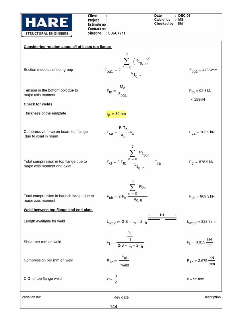
Client : Project : Estimate no : Contract no :Sheet no : C06-C7 / 11
Date : DEC-05Calc'd by : MSChecked by : SM
Considering rotation about c/l of beam top flange
Section modulus of bolt group Zbg1 20
7
n
R10 n,⎛⎝
⎞⎠
2∑=
R10 7,
⋅:= Zbg1 4766 mm=
Tension in the bottom bolt due to major axis moment
FtbMz
Zbg1:= Ftb 92.3kN=
< 158kNCheck for welds
Thickness of the endplate tp 30mm:=
Compressive force on beam top flange due to axial in beam
FcaB Tb⋅
AbAx⋅:= Fca 103.9 kN=
Total compression in top flange due to major axis moment and axial
Fct 2 Ftb⋅0
7
n
R10 n,∑=
R10 7,
⋅ Fca+:= Fct 878.9 kN=
Total compression in haunch flange due to major axis moment
Fcb 2 Ftt⋅0
6
n
R0 n,∑=
R0 6,⋅:= Fcb 869.3 kN=
Weld between top flange and end plateb1
Length available for weld Lweld 2 B⋅ tb− 2 rb⋅−:= Lweld 328.6 mm=
Shear per mm on weld FL
Sh
3
2 B⋅ tb− 2 rb⋅−:= FL 0.015
kNmm
=
Compression per mm on weld FTcFct
Lweld:= FTc 2.675
kNmm
=
C.G. of top flange weld xB2
:= x 95 mm=
Variation no:
Rev date Description
144

Client : Project : Estimate no : Contract no :Sheet no : C06-C7 / 12
Date : DEC-05Calc'd by : MSChecked by : SM
Length of weld on bottom side of beam top flange (each side)
ltB 2 rb⋅− tb−
2:= lt 69.3mm=
Section modulus of weld Zw
B3
122
lt3
12lt
B lt−
2
⎛⎜⎝
⎞
⎠
2
⋅+
⎡⎢⎢⎣
⎤⎥⎥⎦
⋅+
x:= Zw 11914.2 mm2
=
Compression per mm on weld due to minor axis moment
FTw
My
3
Zw:= FTw 0.140
kNmm
=
Total compression on weld per mm FT FTc FTw+:= FTc 2.675kNmm
=
Resultant shear per mm on weld RsFT
1.25
⎛⎜⎝
⎞
⎠
2
FL2
+:= Rs 2.252kNmm
=
Size of weld required sRs
0.7 pw⋅:= s 14.6mm=
9584
.4
90.3
Adopt 15mm CFW
Weld between beam bottom flange to endplate
Tension on beam bottom flange due to 4th bolt row from top due to major axis moment & axial
Ft4R0 3,
R0 6,Ftt⋅
Ax8
+:= Ft4 107.3 kN=
Tension on beam bottom flange due to 5th bolt row from top due to major axis moment
Ft5R0 2,
R0 6,Ftt⋅:= Ft5 42.9kN=
Tension per mm on weld due to majoa axis moment & axial
FTb
2 Ft4⋅69.3
69.3 84.4+⋅
69.3mm 69.3mm+
2 Ft5⋅90.3
90.3 95+⋅
90.3mm 90.3mm++:=
190
69.30 69.30FTb 0.93
kNmm
=
Length available for weld Lweld1 2 190⋅ mm tb− 2 rb⋅−:= Lweld1 328.6 mm=
Shear per mm on weld FL1
Sh
3
2 190⋅ mm tb− 2 rb⋅−:= FL1 0.015
kNmm
=
Variation no:
Rev date Description
145
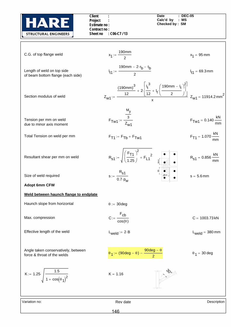
Client : Project : Estimate no : Contract no :Sheet no : C06-C7 / 13
Date : DEC-05Calc'd by : MSChecked by : SM
C.G. of top flange weld x1190mm
2:= x1 95 mm=
Length of weld on top side of beam bottom flange (each side)
lt1190mm 2 rb⋅− tb−
2:= lt1 69.3mm=
Section modulus of weld Zw1
190mm( )3
122
lt3
12lt
190mm lt−
2
⎛⎜⎝
⎞
⎠
2
⋅+
⎡⎢⎢⎣
⎤⎥⎥⎦
⋅+
x:= Zw1 11914.2 mm2
=
Tension per mm on weld due to minor axis moment
FTw1
My
3
Zw1:= FTw1 0.140
kNmm
=
Total Tension on weld per mm FT1 FTb FTw1+:= FT1 1.070kNmm
=
9584
.4
90.3
Resultant shear per mm on weld Rs1FT11.25
⎛⎜⎝
⎞
⎠
2
FL12
+:= Rs1 0.856kNmm
=
Size of weld required sRs1
0.7 pw⋅:= s 5.6 mm=
Adopt 6mm CFW
Weld between haunch flange to endplate
Haunch slope from horizontal θ 30deg:=
Max. compression CFcb
cos θ( ):= C 1003.73 kN=
Effective length of the weld Lweld 2 B⋅:= Lweld 380 mm=
Angle taken conservatively, betweenforce & throat of the welds θ1 90deg θ−( )
90deg θ−
2−:= θ1 30 deg=
K 1.251.5
1 cos θ1( )2+⋅:= K 1.16=
Variation no:
Rev date Description
146

Client : Project : Estimate no : Contract no :Sheet no : C06-C7 / 14
Date : DEC-05Calc'd by : MSChecked by : SM
Compression per mm FThwC
Lweld
My3Zw
+:= FThw 2.781kNmm
=
Shear per mm FL
Sh
3
2B tb− 2rb−:= FL 0.015
kNmm
=
Resultant force per mm FR FL2 FThw
K
⎛⎜⎝
⎞
⎠
2
+:= FR 2.403kNmm
=
Size of weld required sFR
0.7 pw⋅:= s 15.61 mm=
Adopt 16mm CFW
Weld between haunch web to u/s of Beam
313 209
L1 209mm:= L2 313mm:=
Compression at haunch flange C 1003.73 kN=
Shear on the web portion F2 C cos θ( )⋅:= F2 869.3 kN=
Compression at beam bottom flange Fw C sin θ( )⋅:= Fw 501.9 kN=
Size of weld b/w haunch flange to u/s of beam s1 6mm:= (Assumed)
Stiff bearing area Asb L1 tb⋅ tb 1.6 rb⋅+ 5 Tb⋅+( ) 0.8⋅ s1⋅+:= Asb 2521.4 mm2=
Compressive force per mm FT
L1 tb⋅
AsbFw⋅
2 L1⋅:= FT 0.935
kNmm
=
Shear force on weld FLF2
2 L2 L1+( )⋅:= FL 0.833
kNmm
=
Variation no:
Rev date Description
147
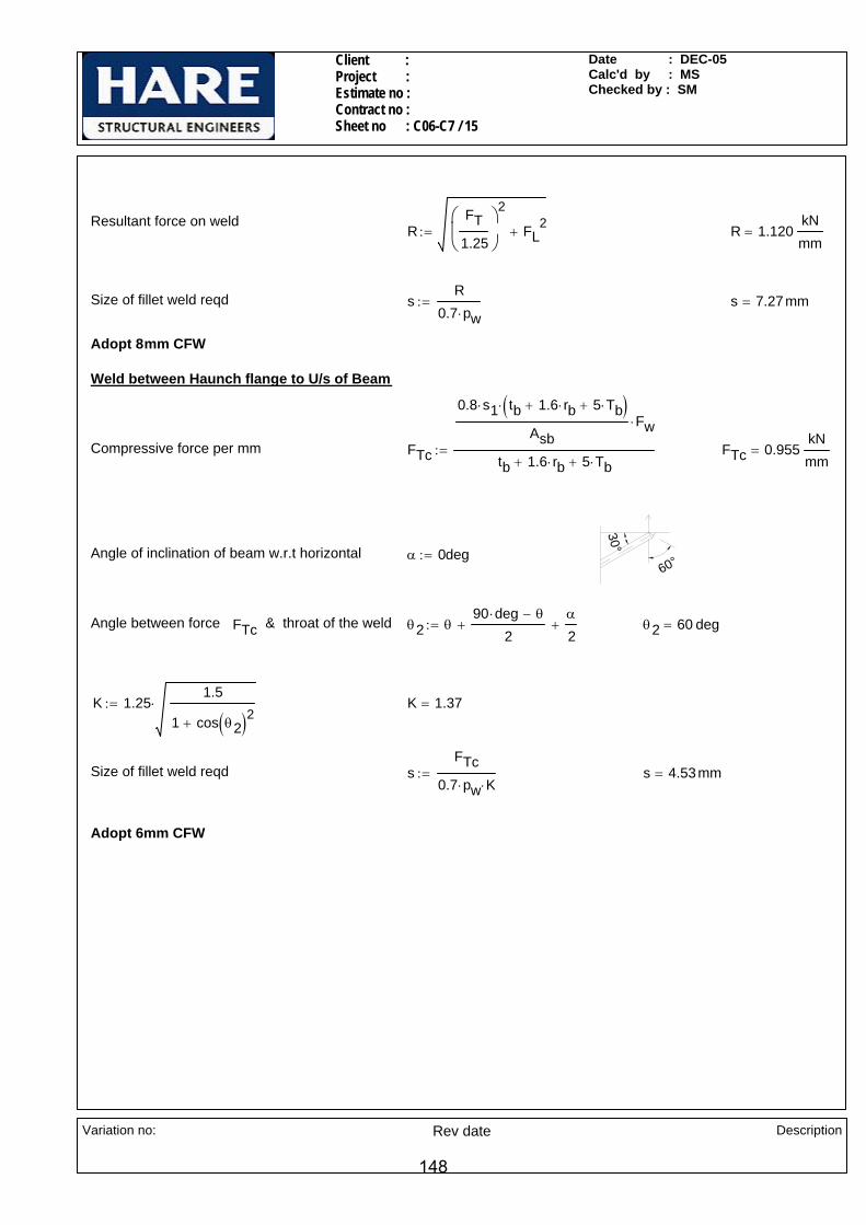
Client : Project : Estimate no : Contract no :Sheet no : C06-C7 / 15
Date : DEC-05Calc'd by : MSChecked by : SM
Resultant force on weldR
FT1.25
⎛⎜⎝
⎞
⎠
2
FL2
+:= R 1.120kNmm
=
Size of fillet weld reqd sR
0.7 pw⋅:= s 7.27mm=
Adopt 8mm CFW
Weld between Haunch flange to U/s of Beam
Compressive force per mm FTc
0.8 s1⋅ tb 1.6 rb⋅+ 5 Tb⋅+( )⋅
AsbFw⋅
tb 1.6 rb⋅+ 5 Tb⋅+:= FTc 0.955
kNmm
=
30°
60°Angle of inclination of beam w.r.t horizontal α 0deg:=
Angle between force FTc & throat of the weld θ2 θ90 deg⋅ θ−
2+
α
2+:= θ2 60 deg=
K 1.251.5
1 cos θ2( )2+⋅:= K 1.37=
Size of fillet weld reqd sFTc
0.7 pw⋅ K⋅:= s 4.53mm=
Adopt 6mm CFW
Variation no:
Rev date Description
148

Client : Project : Estimate no : Contract no : Sheet no : C06-C8/1
Date : DEC-05Calc'd by : SMChecked by : KP
CONNECTION C06-C8 (Moment connection with haunch to stiffened column, analysed using a couple force)
LOADS
Moment Mz 380kN m⋅:=
300x10 THK CAP PLATE
220X10 THK WEB PLATE(10CFW)
2 Nos 140x20 THK STIFFENERS
SECTION A-A
A
150
N/S ONLY
7070
7070
HE 3
20A
15mm PREP.PPBW
88
220 x 25 THK END PLATEBOLTS @ 120 X/CRS
A
HAUNCH O/O HE 500A
HE 500A
2 Nos 25 THK FLANGE BACKING PLATES (TACK WELDED)
110
140
140
140
140
140
120
42(T
YP)
950
800
Vertical shear Fv 900kN:=
Axial force Fa 110kN:=
NOTES:-
All bolts are M30 Grade 8.8.
All welds are 6mm CFW,UNO
All main steel & fittings are S275
Variation no:
Rev date Description
149

Client : Project : Estimate no : Contract no : Sheet no : C06-C8/2
Date : DEC-05Calc'd by : SMChecked by : KP
Design Strength of Weld pw 220N
mm2:=
Bolts
Bolt diameter d 30mm:=
Diameter of hole Dh 33mm:=
Number of bolt rows nr 6:=
Number of bolt columns nc 2:=
Total number of bolts n 12:=
Shear Capacity of bolt Ps 210kN:=
Tension Capacity of bolt Pnom 252kN:=
Distribution of loads for bolt check
Max.Tension Force in top/haunch flange due to moment
TMz
950mmTb2
−Th
2cos 30deg( )−
⎛⎜⎝
⎞
⎠
:= T 410.7 kN=
Max.Tensile Force in top/bottom most bolts due to moment
FtmTnc
:= Ftm 205.4 kN=
Tension per bolt due to axial FtaFan
:= Fta 9.2 kN=
Sectional properties
Column HE 320A
Dc 310 mm⋅:= Wc 300 mm⋅:= Tc 15.5 mm⋅:= tc 9 mm⋅:= dc 225mm:= rc 27 mm⋅:=
Beam HE 500A
Db 490 mm⋅:= Wb 300 mm⋅:= Tb 23 mm⋅:= tb 12 mm⋅:= rb 27 mm⋅:= Ab 19800mm2:=
Haunch o/oHE 500A
Dh 490 mm⋅:= Wh 300 mm⋅:= Th 23 mm⋅:= th 12 mm⋅:= rh 27 mm⋅:=
'
Material Properties
Design strength of S275 materialup to & including 16 thk
py275 275N
mm2⋅:=
Design strength of S275 materialbeyond 16thk , up to and including 40mm thk
py265 265N
mm2⋅:=
Variation no:
Rev date Description
150

Client : Project : Estimate no : Contract no : Sheet no : C06-C8/3
Date : DEC-05Calc'd by : SMChecked by : KP
FTFtLd
:= FT 1.124kNmm
=
Resultant force per mm RFT
1.25
⎛⎜⎝
⎞
⎠
2
FL2
+:= R 1.069kNmm
=
Size of weld required sR
pw 0.7⋅:= s 6.94mm=
Adopt 8 mm CFW
Check for bending capacity of end plate
Bolt gauge g 120mm:=
Weld between beam web & end plate s 8mm:=
Moment MeFt2
g2
tb2
− 0.8s−⎛⎜⎝
⎞
⎠⋅:= Me 5.1 kN m⋅=
Thickness of end plate required treqMe 6⋅
py265 Ld⋅:= treq 24.61 mm=
Adopt 25mm thick end plate
Total tension per bolt due to moment& axial
Ft Ftm Fta+:= Ft 214.5 kN=
Vertical Shear per bolt FsFvn
:= Fs 75 kN=
Combined tension and shear RatioFsPs
FtPnom
+:= Ratio 1.21=
Ratio(1.21 ) < 1.4 : Therefore O.K.
Weld between beam web and end plate
7049
71.8
Available length of weld for shear Lw 2 780mm( )⋅:= Lw 1560 mm=
Shear per mm FLFvLw
:= FL 0.577kNmm
=
Dispersion length Ld 190.8mm:=
Tension per mm
Variation no:
Rev date Description
151
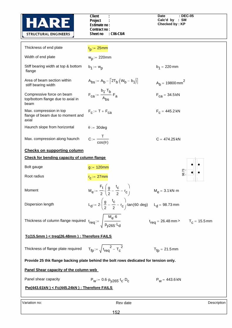
Client : Project : Estimate no : Contract no : Sheet no : C06-C8/4
Date : DEC-05Calc'd by : SMChecked by : KP
g 120mm:=
Root radius rc 27mm:=
Moment MeFt2
g2
tc2
− rc−⎛⎜⎝
⎞
⎠⋅:= Me 3.1 kN m⋅=
Dispersion length Ld 2g2
tc2
− rc−⎛⎜⎝
⎞
⎠⋅ tan 60 deg⋅( )⋅:= Ld 98.73 mm=
Thickness of column flange required treqMe 6⋅
py265 Ld⋅:= treq 26.48 mm= > Tc 15.5mm=
Tc(15.5mm ) < treq(26.48mm ) : Therefore FAILS
Thickness of flange plate required Tfp treq2 Tc
2−:= Tfp 21.5mm=
Provide 25 thk flange backing plate behind the bolt rows dedicated for tension only.
Panel Shear capacity of the column web
Panel shear capacity Pw 0.6 py265⋅ tc⋅ Dc⋅:= Pw 443.6 kN=
Pw(443.61kN ) < Fc(445.24kN ) : Therefore FAILS
Thickness of end plate tp 25mm:=
Width of end plate wp 220mm:=
Stiff bearing width at top & bottom flange
b1 wp:= b1 220 mm=
Area of beam section within stiff bearing width
Abs Ab 2Tb Wb b1−( )⋅⎡⎣ ⎤⎦−:= Ab 19800 mm2=
Compressive force on beam top/bottom flange due to axial in beam
Fcab1 Tb⋅
AbsFa⋅:= Fca 34.5kN=
Max. compression in topflange of beam due to moment andaxial
Fc T Fca+:= Fc 445.2 kN=
Haunch slope from horizontal θ 30deg:=
Max. compression along haunch CT
cos θ( ):= C 474.25 kN=
Checks on supporting column
98.7
3
Check for bending capacity of column flange
Bolt gauge
Variation no:
Rev date Description
152

Client : Project : Estimate no : Contract no : Sheet no : C06-C8/5
Date : DEC-05Calc'd by : SMChecked by : KP
Distance b/w load to nearer end of the member
aeTb2
:= ae 11.5mm=
Distance between fillets dc 225 mm=
ε275265
:= ε 1.019=
Buckling capacity of column web(BS 5950-1,2000,Cl-4.5.3.1)
Pxae 0.7 dc⋅+
1.4 dc⋅
25 ε⋅ tc⋅
b1 n k⋅+( ) dc⋅⋅ Pbw⋅:= Px 238.2 kN=
Capacity of column web P min Pbw Px,( ):= P 238.2 kN=
P(238.18 kN)< Fc(445.24kN ) : Therefore FAILS
Provide 300 x 10 thk cap plate at top & 2Nos 140x20 thk stiffeners in line with haunch flange
( 15t
c )
y
y
ts
tc
WcpCheck for column web buckling with cap plate/stiffener
Thickness of cap plate ts 10mm:=
Width of cap plate Wcp 300mm:=
Length of column web resisting compression buckling
Lo 15 tc×:= Lo 135 mm=
Thickness of web plate twp 10mm:=
Width of web plate bs 220mm:=
Panel shear capacity with 10 thksupplymentary web plate
Pw 0.6 py265⋅ tc⋅ Dc⋅( ) 0.6 py265⋅ bs⋅ twp⋅( )+:= Pw 793.4 kN=
Fc(445.24kN ) < Pw(793.41kN ) : Therefore O.K.
Hence adopt 10 thk web plate
Compression capacity of column web
Distance to the nearer end of a member from the end of stiff bearing
be 0mm:=
k Tc rc+:= k 42.5mm=
At the end of a member n 2 0.6bek
⋅+:= n 2= (BS 5950-1,2000,Cl-4.5.2.1)
Dispersion length b1 Tb 0.8 6⋅ mm+ tp+:= b1 52.8mm=
Bearing capacity of column web Pbw b1 n k⋅+( ) tc⋅ py275⋅:= Pbw 341.1 kN=
Variation no:
Rev date Description
153

Client : Project : Estimate no : Contract no : Sheet no : C06-C8/6
Date : DEC-05Calc'd by : SMChecked by : KP
Lweld 600 mm=
Compression per mm FTsFcs
Lweld:= FTs 0.345
kNmm
=
Size of weld required sreqdFTs
0.7 pw⋅ 1.25⋅:= sreqd 1.79mm=
Adopt 6mm CFW
Weld between Stiffener and column flange
e
0.5xFcs
0.5xFcs
Width of stiffener Wst 140mm:=
Eccentricity b/w compression & face of col web
e 70mm:=
Moment due to compression eccentricity
Mcomp 0.5Fcs e⋅:= Mcomp 7.2 kN m⋅=
Couple force on weld due to moment FcoMcomp
Dc 2 Tc⋅−( ):= Fco 26 kN=
Length of weld Lw 2 Wst⋅ 2 27⋅ mm−:= Lw 226 mm=
Moment of inertia of the section IyyWcp ts
3×
12
Lo tc3
×
12+
⎛⎜⎜⎝
⎞
⎠:= Iyy 33201.3 mm4
=
A Wcp ts× Lo tc⋅+( ):= A 4215 mm2=
Min radius of gyration ryyIyyA
:= ryy 2.8 mm=
λ0.7 dc⋅
ryy:= λ 56.12=
pc 227.1N
mm2= From Table-24,Strut Curve c, BS-5950-1(2000)
Buckling capacity Px A pc⋅:= Px 957.2 kN=
Fc(445.24kN ) < Px(957.22 kN) : Therefore cap plate thickness is O.K.
Weld between cap plate and column flange
Compression to be resisted by stiffener
Fcs Fc P−:= Fcs 207.1 kN=
Length of weld available Lweld 2 Wcp⋅:=
Variation no:
Rev date Description
154
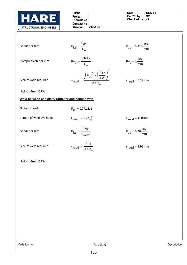
Client : Project : Estimate no : Contract no : Sheet no : C06-C8/7
Date : DEC-05Calc'd by : SMChecked by : KP
Adopt 6mm CFW
sreqd 2.99mm=sreqdFLs
0.7 pw⋅:=Size of weld required
FLs 0.46kNmm
=FLsFcs
Lweld:=Shear per mm
Lweld 450 mm=Lweld 2 dc( )⋅:=Length of weld available
Fcs 207.1 kN=Shear on weld
Weld between cap plate/ Stiffener and column web
Adopt 6mm CFW
sreqd 5.17mm=sreqd
FLs2 FTc
1.25
⎛⎜⎝
⎞
⎠
2
+
0.7 pw⋅:=Size of weld required
FTc 1kNmm
=FTc0.5 Fc⋅
Lw:=Compression per mm
FLs 0.115kNmm
=FLsFcoLw
:=Shear per mm
Variation no:
Rev date Description
155
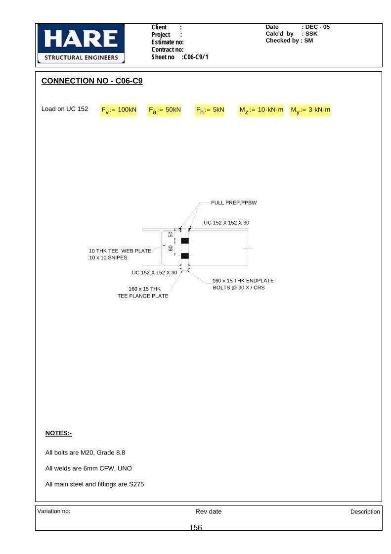
Client : Project : Estimate no: Contract no: Sheet no :C06-C9/ 1
Date : DEC - 05Calc'd by : SSKChecked by : SM
CONNECTION NO - C06-C9
Load on UC 152 Fv 100kN:= Fa 50kN:= Fh 5kN:= Mz 10 kN⋅ m⋅:= My 3 kN⋅ m⋅:=
UC 152 X 152 X 30
10 x 10 SNIPES10 THK TEE WEB PLATE
160 x 15 THK BOLTS @ 90 X / CRS
6050
UC 152 X 152 X 30
FULL PREP.PPBW
TEE FLANGE PLATE
160 x 15 THK ENDPLATE
NOTES:-
All bolts are M20, Grade 8.8
All welds are 6mm CFW, UNO
All main steel and fittings are S275
Variation no: Rev date Description
156
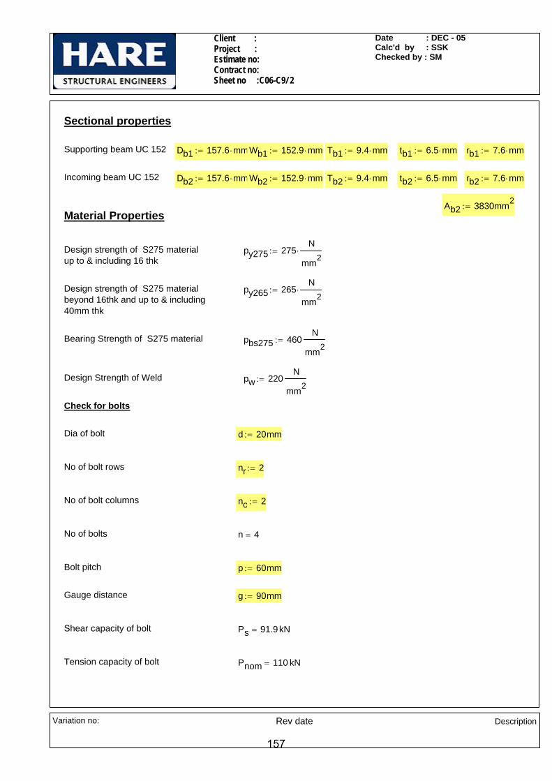
Client : Project : Estimate no: Contract no: Sheet no :C06-C9/ 2
Date : DEC - 05Calc'd by : SSKChecked by : SM
Sectional properties
Supporting beam UC 152 Db1 157.6 mm⋅:= Wb1 152.9 mm⋅:= Tb1 9.4 mm⋅:= tb1 6.5 mm⋅:= rb1 7.6 mm⋅:=
Incoming beam UC 152 Db2 157.6 mm⋅:= Wb2 152.9 mm⋅:= Tb2 9.4 mm⋅:= tb2 6.5 mm⋅:= rb2 7.6 mm⋅:=
Ab2 3830mm2:=
Material Properties
Design strength of S275 materialup to & including 16 thk
py275 275N
mm2⋅:=
Design strength of S275 materialbeyond 16thk and up to & including 40mm thk
py265 265N
mm2⋅:=
Bearing Strength of S275 material pbs275 460N
mm2:=
Design Strength of Weld pw 220N
mm2:=
Check for bolts
Dia of bolt d 20mm:=
No of bolt rows nr 2:=
No of bolt columns nc 2:=
No of bolts n 4=
Bolt pitch p 60mm:=
Gauge distance g 90mm:=
Shear capacity of bolt Ps 91.9kN=
Tension capacity of bolt Pnom 110 kN=
Variation no: Rev date Description
157

Client : Project : Estimate no: Contract no: Sheet no :C06-C9/ 3
Date : DEC - 05Calc'd by : SSKChecked by : SM
Clockwise moment
Taking rotation about centre of beam bottom flange
Rc 42.9 102.9( )mm:=
Section modulus of bolt group( major axis)
Zp
2
0
1
n
Rc0 n,⎛⎝
⎞⎠
2∑=
⋅⎡⎢⎢⎣
⎤⎥⎥⎦
Rc0 1,
:= Zp 241.57 mm=
Tensile force on Single boltdue to Mz
FttMzZp
:= Ftt 41.4kN=
Reversal moment
Taking rotation about centre of beam top flange
Rr 45.3 105.3( )mm:=
Section modulus of bolt group( major axis)
Zn
2
0
1
n
Rr0 n,⎛⎝
⎞⎠
2∑=
⋅⎡⎢⎢⎣
⎤⎥⎥⎦
Rr0 1,
:= Zn 249.58 mm=
Tensile force on Single boltdue to Mz
FtbMzZn
:= Ftb 40.1kN=
Section modulus of bolt group( minor axis)
Zp1 2 g⋅:= Zp1 180 mm=
Tensile force on Single boltdue to My
FtmMyZp1
:= Ftm 16.7kN=
Tension per bolt due to axial force &moments
FtFan
max Ftt Ftb,( )+ Ftm+:= Ft 70.56 kN=
C .G of bolt group from top bolt y 30mm:= y 30 mm=
xg2
:= x 45 mm=
Eccentricity of c/l of beam top flange from c.g of bolt group
e1 75.3mm:=
Moment due to hor. shear eccentricity
Mt Fh e1⋅:= Mt 0.38kN m⋅=
Inertia of bolt group Ibg 4 452⋅ 4 302
⋅+( ) mm2⋅:= Ibg 11700 mm2
=
Variation no: Rev date Description
158
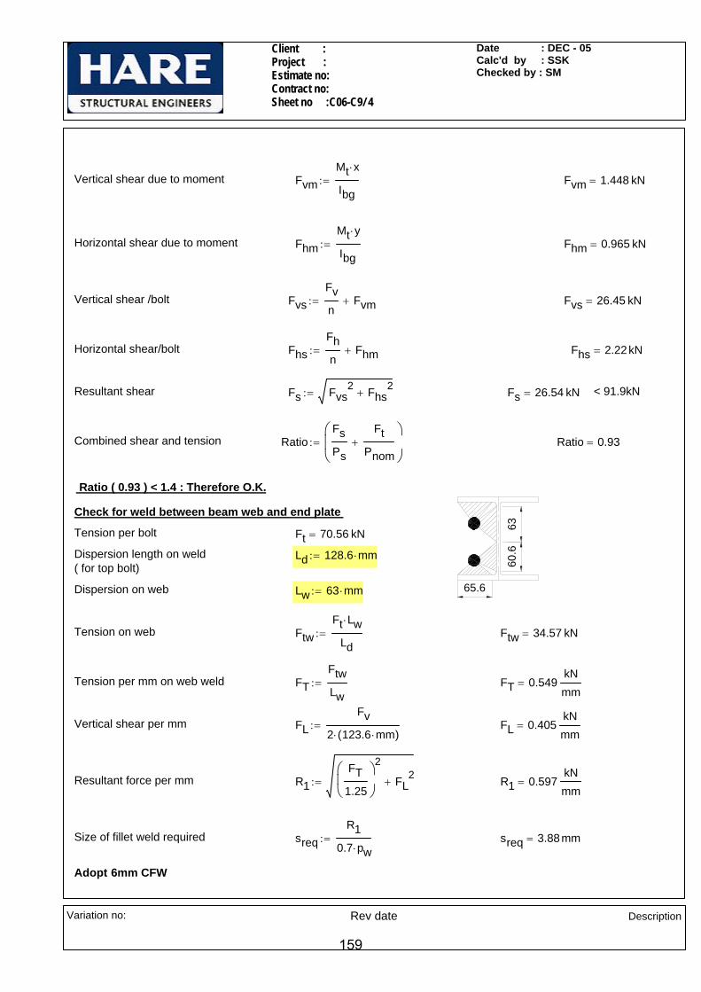
Client : Project : Estimate no: Contract no: Sheet no :C06-C9/ 4
Date : DEC - 05Calc'd by : SSKChecked by : SM
Vertical shear due to moment FvmMt x⋅
Ibg:= Fvm 1.448 kN=
Horizontal shear due to moment FhmMt y⋅
Ibg:= Fhm 0.965 kN=
Vertical shear /bolt FvsFvn
Fvm+:= Fvs 26.45 kN=
Horizontal shear/bolt FhsFhn
Fhm+:= Fhs 2.22kN=
Resultant shear Fs Fvs2 Fhs
2+:= Fs 26.54 kN= < 91.9kN
Combined shear and tension RatioFsPs
FtPnom
+⎛⎜⎜⎝
⎞
⎠:= Ratio 0.93=
Ratio ( 0.93 ) < 1.4 : Therefore O.K.
63
65.6
60.6
Check for weld between beam web and end plate
Tension per bolt Ft 70.56 kN=
Dispersion length on weld( for top bolt)
Ld 128.6 mm⋅:=
Dispersion on web Lw 63 mm⋅:=
Tension on web FtwFt Lw⋅
Ld:= Ftw 34.57 kN=
Tension per mm on web weld FTFtwLw
:= FT 0.549kNmm
=
Vertical shear per mm FLFv
2 123.6 mm⋅( )⋅:= FL 0.405
kNmm
=
Resultant force per mm R1FT
1.25
⎛⎜⎝
⎞
⎠
2
FL2
+:= R1 0.597kNmm
=
Size of fillet weld required sreqR1
0.7 pw⋅:= sreq 3.88mm=
Adopt 6mm CFW
Variation no: Rev date Description
159
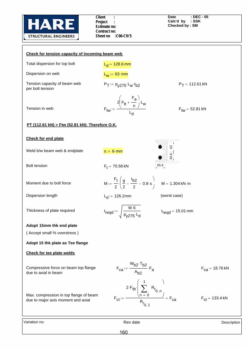
Client : Project : Estimate no: Contract no: Sheet no :C06-C9/ 5
Date : DEC - 05Calc'd by : SSKChecked by : SM
Check for tension capacity of incoming beam web
Total dispersion for top bolt Ld 128.6 mm=
Dispersion on web Lw 63 mm⋅:=
Tension capacity of beam web per bolt tension
PT py275 Lw⋅ tb2⋅:= PT 112.61 kN=
Tension in web Ftw
2 FttFan
+⎛⎜⎝
⎞
⎠Lw⋅
Ld:= Ftw 52.81 kN=
PT (112.61 kN) > Ftw (52.81 kN): Therefore O.K.
63
65.6
60.6
Check for end plate
Weld b/w beam web & endplate s 6 mm⋅:=
Bolt tension Ft 70.56 kN=
Moment due to bolt force MFt2
g2
tb22
− 0.8 s⋅−⎛⎜⎝
⎞
⎠⋅:= M 1.304 kN m⋅=
Dispersion length Ld 126.2mm:= (worst case)
Thickness of plate required treqdM 6⋅
py275 Ld⋅:= treqd 15.01 mm=
Adopt 15mm thk end plate
( Accept small % overstress )
Adopt 15 thk plate as Tee flange
Check for tee plate welds
Compressive force on beam top flange due to axial in beam
FcaWb2 Tb2⋅
Ab2Fa⋅:= Fca 18.76 kN=
Max. compression in top flange of beam due to major axis moment and axial Fct
2 Ftb⋅
0
1
n
Rr0 n,∑=
⎛⎜⎜⎝
⎞
⎠
⋅
Rr0 1,
Fca+:= Fct 133.4 kN=
Variation no: Rev date Description
160

Client : Project : Estimate no: Contract no: Sheet no :C06-C9/ 6
Date : DEC - 05Calc'd by : SSKChecked by : SM
Max.compression in bottom flange of beamdue to major axis moment and axial Fcb
2 Ftt⋅
0
1
n
Rc0 n,⎛⎝
⎞⎠∑
=
⎡⎢⎢⎣
⎤⎥⎥⎦
⋅
Rc0 1,
Fca+:= Fcb 136.1 kN=
Weld between end plate/toe plate and UC 152 top flange
Stiff bearing length b1 Wb2:= b1 152.9 mm=
Length available for weld Lweld b1:= Lweld 152.9 mm=
Shear per mm on weld FLFh
Lweld:= FL 0.03
kNmm
=
Section modulus of weld ZwLweld
2
6:= Zw 3896.4 mm2
=
Max Compression per mm FTFct
Lweld
My
2
Zw+:= FT 1.257
kNmm
=
Resultant shear per mm on weld RFL0.6
⎛⎜⎝
⎞
⎠
2
FT2
+:=
Size of PPBW required s max 2 9.4⋅ 3+( )mmR
py2753mm+
⎛⎜⎝
⎞
⎠,
⎡⎢⎣
⎤⎥⎦
:= s 9.13mm=
152.90
65.60
21.70
43.65Adopt full prep.PPBW
Weld between bottom flange and end plate/toe plate
Length available for weld Lweld 2b1 tb2− 2rb2−:= Lweld 284.1 mm=
Section modulus of weld Zw
Wb13
122
65.6 mm⋅( )3
1265.6 mm⋅ 43.65 mm⋅( )2⋅+
⎡⎢⎣
⎤⎥⎦
⋅+
Wb1
2
:=
Zw 7781.66 mm2=
Max Compression per mm FTbFcb
Lweld
My
2
Zw+:= FTb 0.672
kNmm
=
Size of FW required sFTb
0.7 1.25⋅ pw⋅:= s 3.49mm=
Adopt 6mm CFW
Variation no: Rev date Description
161

Client : Project : Estimate no: Contract no: Sheet no :C06-C9/ 7
Date : DEC - 05Calc'd by : SSKChecked by : SM
Weld between tee web and UC 152 flange
38.2
0
44.78 kN
2 x 26.14 kN
2 x 14.17 kN6040
.60
63.2Tension dispersed to TEE web platefrom tension in first row of bolt
Ft0
Fan
Ftt+⎛⎜⎝
⎞
⎠70.6⋅ mm⋅
70.6 mm⋅ 75 mm⋅+:= Ft0 26.13 kN=
ension dispersed to TEE web platefrom tension in second row of bolt
Ft1
Fan
FttRc0 1,
Rc0 0,⋅+
⎛⎜⎜⎝
⎞
⎠68.2⋅ mm⋅
68.2 mm⋅ 75 mm⋅+:= Ft1 14.17 kN=
Max shear on the weld/side Fmax2 Ft0 98.20⋅ mm Ft1 38.20⋅ mm+( )
38.20 60+ 40.60+( )mm:= Fmax 44.78 kN=
Length available for weld/side( using 10 x 10 snipes)
Lweld 73.2mm 10mm−:=75.0
70.6
68.2
38.2
75.0
40.6
60.0
Lweld 63.2mm=
Shear per mm FLFmax
2Lweld:= FL 0.354
kNmm
=
Size of fillet weld required sreqFL
0.7 pw⋅:= sreq 2.30mm=
Adopt 6mm CFW
Weld between UC 152 beam web and tee web
Vertical shear per mm FLFv
2 123.6 mm⋅( )⋅:= FL 0.405
kNmm
=
Size of fillet weld required sreqFL
0.7 pw⋅:= sreq 2.63mm=
Adopt 6mm CFW
Check for tee web plate
Width of web plate w 63.2mm:=
Thickness of plate required in shear treqFmax
0.6 0.9⋅ w⋅ py275⋅:= treq 4.77mm=
Adopt 10 thk plate as Tee web
Variation no: Rev date Description
162
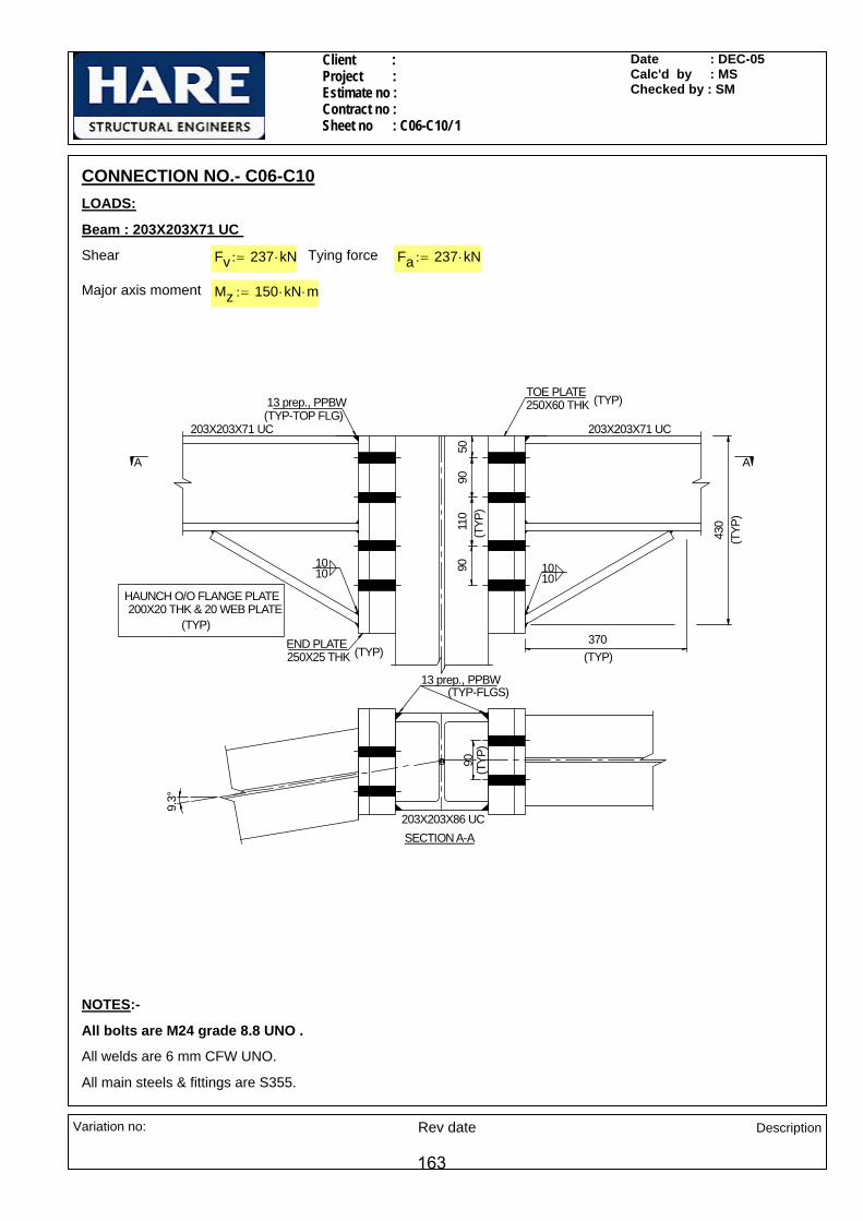
Client : Project :Estimate no : Contract no : Sheet no : C06-C10/ 1
Date : DEC-05 Calc'd by : MS Checked by : SM
CONNECTION NO.- C06-C10LOADS:
Beam : 203X203X71 UC
Shear Fv 237 kN⋅:= Tying force Fa 237 kN⋅:=
Major axis moment Mz 150 kN⋅ m⋅:=
5090
110
90(T
YP)
370
430
(TYP)
(TYP
)
90(T
YP)
13 prep., PPBW(TYP-TOP FLG)
END PLATE 250X25 THK (TYP)
TOE PLATE 250X60 THK (TYP)
203X203X71 UC 203X203X71 UC
HAUNCH O/O FLANGE PLATE 200X20 THK & 20 WEB PLATE
(TYP)
10
203X203X86 UC
9.3°
A A
SECTION A-A
101010
13 prep., PPBW(TYP-FLGS)
NOTES:-
All bolts are M24 grade 8.8 UNO .
All welds are 6 mm CFW UNO.
All main steels & fittings are S355.
Variation no: Rev date Description
163

Client : Project :Estimate no : Contract no : Sheet no : C06-C10/ 2
Date : DEC-05 Calc'd by : MS Checked by : SM
SECTIONAL PROPERTIES
Supporting column : 203X203X86
Dc 222.2mm:= wc 209.1mm:= Tc 20.5mm:= tc 12.7mm:= rc 10.2mm:= Ac 11000 mm2=
Supported beam : 203X203X71
Db 215.8mm:= wb 206.4mm:= Tb 17.3mm:= tb 10mm:= rb 10.2mm:= db 160.8mm:= Ab 9040 mm2=
MATERIAL PROPERTIES
Design strength of S355 material up to & including 16 mm thk. py355 355N
mm2⋅:=
Design strength of S355 material beyond 16 mm thk and including 40 mm thk. py345 345N
mm2⋅:=
Design strength of S355 material beyond 40 mm thk and including 60 mm thk. py335 335N
mm2⋅:=
Design Ultimate strength of S355 material pu 392N
mm2⋅:=
Design strength of weld pw 250N
mm2⋅:=
Check for bolts b/w end plate & beam web (Worst case)
Dia of bolt d 24mm:=
No of bolt rows nr 4:=
No of bolt columns nc 2:=
Total no of bolts n 8=
Pitch p 90mm:=
Shear capacity of bolt Ps 132 kN=
Tension capacity of bolt Pnom 158 kN=
Check for bolts
Considering rotation about c/l of haunch flange
Bolt lever arm distances Rt 78.45 168.45 278.45 368.45( )mm:=
Section modulus of bolt group Zbg 20
3
n
Rt0 n,⎛⎝
⎞⎠
2∑=
Rt0 3,
⋅:= Zbg 1345.20 mm=
Variation no: Rev date Description
164

Client : Project :Estimate no : Contract no : Sheet no : C06-C10/ 3
Date : DEC-05 Calc'd by : MS Checked by : SM
Tension in the top most bolt due to major axis moment
FttMzZbg
:= Ftt 111.51 kN=
Considering rotation about c/l of beam top flange
Bolt lever arm distances Rt1 41.35 131.35 241.35 331.35( )mm:=
Section modulus of bolt group Zbg 20
3
n
Rt10 n,⎛⎝
⎞⎠
2∑=
Rt10 3,
⋅:= Zbg 1128.75 mm=
Moment induced on end plate & toe plateinterface due to eccentricity
Mz1 Fv 64.55⋅ mm:= Mz1 15.3kN m⋅=
Tension in the top most bolt due to major axis moment
FtbMz Mz1+
Zbg:= Ftb 146.44 kN= < 158kN
203X203X86 UC
64.55
Vertical shear per bolt FsFvn
:= Fs 29.6kN=
Max. tension per bolt Ft max Ftt Ftb,( ):= Ft 146.44 kN=
< 158kN
Combined shear & tension RatioFsPs
FttPnom
+:= Ratio 0.93=
Ratio (0.93 ) < 1.4 : Therefore O.K.
Tension per bolt due to tie force Ft1Fa4
:= Ft1 59.25 kN=
Ft1 (59.25kN)< 158kN Therefore O.K.
90
90
111.
89
Check for weld between end plate and beam web
Eff. shear length for weld Ls db 190.09mm+:= Ls 350.9 mm=
Shear per mm FLFv
2 Ls⋅:= FL 0.338
kNmm
=
Tension per mm due to tie force FT
Ft111.89201.89
⎛⎜⎝
⎞⎠
⋅
111.89mm:= FT 0.725
kNmm
=
Size of the weld for shear & tension due to induced moment
sw
FL2 FT
1.25
⎛⎜⎝
⎞
⎠
2
+
pw 0.7⋅:= sw 3.84mm=
sw 6mm:=Adopt 6mm CFW
Variation no: Rev date Description
165

Client : Project :Estimate no : Contract no : Sheet no : C06-C10/ 4
Date : DEC-05 Calc'd by : MS Checked by : SM
Check for end plate
Moment induced on end plate M1Ft2
90mmtb2
− 0.8 sw⋅−⎛⎜⎝
⎞
⎠⋅:= M1 5.9 kN m⋅=
Thickness of end plate required tpreqd6 M1⋅
py345 201.89⋅ mm:= tpreqd 22.49 mm=
Adopt 25mm thk end plate.tp 25mm:=
222.
20
187.
55
Check for toe plate (worst case-for compression)
Total compression in haunch flange dueto major axis moment
Fcb 2 Ftt⋅0
3
n
Rt0 n,∑=
Rt0 3,
⋅:= Fcb 541 kN=
222.
20A
B18
7.55
3.51
kN/m
m
Total compression in top flange due tomajor axis moment
Fct 2 Ftb⋅0
3
n
Rt10 n,∑=
Rt10 3,
⋅:= Fct 658.9 kN=
Compression acting on top flange per mm
CwFct
187.55mm:= Cw 3.51
kNmm
=
Max BM acting on toe plate due to compression
M2 20.6kN m⋅:= (Refer PROKON output)
Assume thickness of toe plate ttp 60mm:=
Assume beam top flange weld sw2 13mm:=
Stiff bearing width @ centre of toe plate
Ld1 sw2 tp+ 2.5ttp2
⋅+:= Ld1 113 mm=
Ld1 113.00 mm=
Thickness of toe plate required for compression
tpreqd6 M2⋅
py335 Ld1⋅:= tpreqd 57.14 mm=
Adopt 60mm Thk toe plate
Check for weld b/w toe plate & column flange ( worst case-for compression)
Compression acting on each weld per mm
FTcw
Fct
2
Ld1:= FTcw 2.9
kNmm
=
Size of PPBW weld required swc max 2 20.5 3+( ) mm⋅FTcwpy345
3 mm⋅+,⎡⎢⎢⎣
⎤⎥⎥⎦
:= swc 12.06 mm=
Adopt 13 prep., PPBW.
Variation no: Rev date Description
166

Client : Project :Estimate no : Contract no : Sheet no : C06-C10/ 5
Date : DEC-05 Calc'd by : MS Checked by : SM
90
111.
8967
.5
86.44Check for tension capacity of incoming beam web
Max tension on 1st row of bolt dispersed on beam web
Ftw Ftt67.5
67.5 86.44+⋅:= Ftw 48.9kN=
Total tension acting on beam web FtW 2 Ftw⋅:= FtW 97.8kN=
Tension capacity of incoming beam web Ptw 67.5mm pu⋅ tb⋅:= Ptw 264.6 kN=
FtW ( 97.79 kN ) < Ptw ( 264.6 kN ): Therefore O.K.
Check for haunch section (Compression capacity)
191.
09
191.09 138.99
45°
69.64
381.40
Depth of Haunch dh 191.09 mm⋅:=
Effective depth of haunch web dhw 69.64 mm⋅:=
Thickness of haunch web th 20 mm⋅:=
Width of haunch flange wh 200 mm⋅:=
Thickness of haunch flange Th 20 mm⋅:=
Use 200 x 20 thk. haunch flange plate & 20 thk. haunch web plate
Area of effective haunch section Ah dhw th⋅ wh Th⋅+:= Ah 5392.8 mm2=
Max. compression CFcb
cos 30 deg⋅( ):= C 624.69 kN=
C.g of T-section about X-X axis Cx
wh Th2
⋅
2dhw th⋅ Th
dhw2
+⎛⎜⎝
⎞
⎠⋅+
wh Th⋅ dhw th⋅+:= Cx 21.58 mm=
Moment of inertia about XX axis,
Ixxwh Th
3⋅
12wh Th⋅ Cx
Th2
−⎛⎜⎝
⎞
⎠
2
⋅+dhw
3 th⋅
12+ dhw th⋅ Cx Th−
dhw2
−⎛⎜⎝
⎞
⎠
2
⋅+:= Ixx 2771512.2 mm4=
Moment of inertia Iyywh
3 Th⋅
12
dhw th3
⋅
12+:= Iyy 13379760 mm4
=
Min. Radius of gyration rymin Iyy Ixx,( )
Ah:= ry 22.7mm=
Length of haunch L 381.4 mm⋅:=
Variation no: Rev date Description
167

Client : Project :Estimate no : Contract no : Sheet no : C06-C10/ 6
Date : DEC-05 Calc'd by : MS Checked by : SM
k 1:=
Slenderness ratio λk L⋅ry
:=λ 16.8=
Unit compressive resisistace fc 355N
mm2:=
Factored compressive resistance Cr fc Ah⋅:= Cr 1914.4 kN=
Cr (1914.44 kN) > C (624.69 kN): Therefore O.K.
Weld between haunch flange and end plate
Stiff bearing width b1 wb:= b1 206.4 mm=
Length available for weld Lweld 2 wh⋅ th−:= Lweld 380 mm=
Compression per mm on weld FTc1C
Lweld:= FTc1 1.644
kNmm
=
Angle taken conservatively, betweenforce & throat of the welds θ1 30deg:=
K 1.251.5
1 cos θ1( )2+⋅:= K 1.16=
Size of weld required sw1FTc1
0.7 K⋅ pw⋅:= sw1 8.12mm=
Adopt 10mm CFW sw1 10mm:=
Weld between top flange and end plate
Length available for weld Lweld b1:= Lweld 206.4 mm=
Compression per mm on weld FTcFct
Lweld:= FTc 3.192
kNmm
=
Size of PPBW weld required sw2 max 2 17.3 3+( ) mm⋅FTc
py3453 mm⋅+,
⎡⎢⎢⎣
⎤⎥⎥⎦
:= sw2 12.25 mm=
Adopt 13 prep., PPBW. sw2 13mm:=
Weld between haunch web to u/s of Beam
191.
09
191.09 138.99
45°
L1 138.99mm:= L2 191.09mm:=
Compression at haunch flange C 624.69 kN=
Shear on the web portion F2 C cos θ1( )⋅:= F2 541 kN=
Compression at beam bottom flange Fw C sin θ1( )⋅:= Fw 312.3 kN=
Size of weld ( Assumed) sw4 6mm:=
Stiff bearing area Asb L1 tb⋅ tb 1.6 rb⋅+ 5 Tb⋅+( ) 0.8⋅ sw4⋅+:= Asb 1931.44 mm2=
Variation no: Rev date Description
168

Client : Project :Estimate no : Contract no : Sheet no : C06-C10/ 7
Date : DEC-05 Calc'd by : MS Checked by : SM
Compressive force per mm FT4
L1 tb⋅
AsbFw⋅
2 L1⋅:= FT4 0.809
kNmm
=
Shear force on weld FL3F2
2 L2 L1+( )⋅:= FL3 0.819
kNmm
=
Resultant force on weld RFT41.25
⎛⎜⎝
⎞
⎠
2
FL32
+:= R 1.044kNmm
=
Size of fillet weld reqd sw3R
0.7 pw⋅:= sw3 5.97mm=
Adopt 6mm CFW
Weld between Haunch flange to U/s of Beam
Compressive force per mm FTc
0.8 sw4⋅ tb 1.6 rb⋅+ 5 Tb⋅+( )⋅
AsbFw⋅
tb 1.6 rb⋅+ 5 Tb⋅+:= FTc 0.776
kNmm
=
Angle between force FTc & throat of the weld θ2 θ190 deg⋅ θ1−
2+:=
θ2 60.00 deg=
K 1.251.5
1 cos θ2( )2+⋅:= K 1.37=
Size of fillet weld reqd sw4FTc
0.7 pw⋅ K⋅:= sw4 3.24mm=
Adopt 6mm CFWsw4 6mm:=
191.
09
191.09 138.99
45°
381.4
Weld b/w haunch flange to haunch web
Shear acting on weld per mm FL4C
2 381.4⋅ mm:= FL4 0.8
kNmm
=
Size of fillet weld reqd sw5FL4
0.7 pw⋅:= sw5 4.68mm=
Adopt 6mm CFW
Variation no: Rev date Description
169

SheetJob Number
Job Title
Client
Calcs by MS Checked by SM Date DEC-05
Software Consultants (Pty) LtdInternet: http://www.prokon.comE-Mail : [email protected]
C06-C10/8MACEMS KP DEC-05
A11Single Span Beam : Untitled
Input Tables
Section DesignationIPE100 I1
Beam Data Length (m)Fixity leftFixity right I (m4) E (kPa)
0.2222PinnedPinned
1.710E-6206E6
LoadsW left(kN/m)
W right(kN/m)
a(m)
b(m)
P(kN)
a(m)
M(kNm)
a(m)
3510 3510 0 0.1875
Moment, Shear and Deflections
0.19
3510.0
I = 1.71E-6 m^4 E = 206E6 kPa
0.03
I = 1.71E-6 m^4 E = 206E6 kPa
DEFLECTIONS D max = -.298mm @ .110m
-.300-.280-.260-.240-.220-.200-.180-.160-.140-.120-.100-.080-.060-.040-.020
.010
.020
.030
.040
.050
.060
.070
.080
.090
.100
.110
.120
.130
.140
.150
.160
.170
.180
.190
.200
.210
.220
SHEAR FORCE V max = 380 kN @ 0.00m
-250-200-150-100
-50.0
50.0100 150 200 250 300 350 400
.010
.020
.030
.040
.050
.060
.070
.080
.090
.100
.110
.120
.130
.140
.150
.160
.170
.180
.190
.200
.210
.220
BENDING MOMENT M max = 20.6kNm @ .110m
20.019.018.017.016.015.014.013.012.011.010.09.008.007.006.005.004.003.002.001.00
.010
.020
.030
.040
.050
.060
.070
.080
.090
.100
.110
.120
.130
.140
.150
.160
.170
.180
.190
.200
.210
.220
170

Client : Project : Estimate no : Contract no : Sheet no : C06-C11 / 1
Date : DEC-05Calc'd by : SMChecked by : MS
All main steel & fittings are S275
All weld sizes are 6mm CFW U.N.O
All bolts are M20 ,Grade 8.8 U.N.O
NOTES:-
SECTION A-A
8 deg
HE 1000A
A
HE 1000A
8 deg
(typ flanges)
(typ flanges)
A
End plate300 x 40thk
Fin plateAs opp.side
IPE 300
B
75
IPE 300
B 175
(typ)
110
110
110
110
220220
HE 1000A
SECTION B-B
IPE 300
228.8 kN286 kN
171.6 kN
53.1
3°
IPE 300
171.6 kN
228.8 kN286 k
N53.13°28
6 kN
171.6 kN
228.8 kN
53.13°
228.8 kN
286 kN
53.1
3°
171.6 kN
HE 24
0A (T
YP)
(TYP
)
Gusset15 thk (typ)
4070
40
90 (typ)
300
(min
)(ty
p)
120
5011
011
014
016
0
20 (min)(typ)
40 5040
250 (max)
(typ)
5090
7070
80
20 Nos M24 BOLTS
1515
1515
Fv1 30kN:=Vertical shear
F2 286kN:=Axial BRACES HE 240A(K-LOADING)
Fa 155kN:=Axial INCOMING BEAMS IPE300(G-LOADING)
Fh 25kN:=Horizontal shearFv 72kN:=Vertical shearF 384kN:=Axial
Mv 942kN m⋅:=Moment RAFTER HE 1000A
LOADS ( B & D TYPE LOADING)
CONNECTION NO - C06-C11
Variation no: Rev date Description
171

© MasterKey Joints - KAZAKHSTAN C:\Documents and Settings\MURALI.WHILDESIGN\Desktop\2002
25125William Hare LimitedBrandlesholme House, Brandlesholme RoadBury, Manchester BL8 1JJwww.williamhare.comTel: 0161 6090000 Fax: 0161 6090409
Job RefSheetMade byDateCheckedApproved
: : C06-C11 / 002: SM: December, 2005/ Ver. 2003.12: MS:
© Civil and Structural Computer Services Limited, 1 Circular Road, Newtownabbey, Co. Antrim BT37 0RA, Tel: 028 9036 5950 Fax: 028 9036 5102
Connection-C06-C11Beam to Beam End-Plated Connection
15fw
15fw
6fw
50140
140
110110110
50160
110110
110•
100
999•
101
End-Plate 1200 x 300 x 40 mm20 No. M24 8.8 Bolts in 26 mm holes
120
Welds grd 42 Plates S 275Beam HE 1000 A 272.27 [S 275]
8 deg
Left Hand Side - Loading Case 01Basic Data
Applied Forces at End-plate InterfaceLeft Rafter Forces M, Fvr, Fr +942.0 kNm, +72.0 kN, +384.0 kNResultant Forces M, Fv, F +942.0 kNm, +17.9 kN, +390.3 kNLoad directions Top of Joint in Tension, Rafter moving Down and in Compression.Design to BS 5950-1: 2000 and the SCI Green Book:
Joints in Steel Construction : Moment Connections: SCI-P-207/95
Basic DimensionsRafter-HE 1000 A 272.27 [28] D=990, B=300, T=31, t=16.5, r=30.0, py=265Rafter Capacities Mc, Fvc, Fc 3443.3 kN.m, 2622.8 kN, 9233.9 kN Mc = 3443.3 kN.m OK
Summary of Results (Unity Ratios)Moment Capacity(for 9 rows of bolts) 0.57 OKMoment Capacity(for the 3 rows of bolts required in the tension zone) 0.81 OKShear Capacity 0.01 OKFlange Welds 0.60, 0.89 0.89 OKWeb Welds 0.73, 0.02 0.73 OK
172

© MasterKey Joints - KAZAKHSTAN C:\Documents and Settings\MURALI.WHILDESIGN\Desktop\2002
25125William Hare LimitedBrandlesholme House, Brandlesholme RoadBury, Manchester BL8 1JJwww.williamhare.comTel: 0161 6090000 Fax: 0161 6090409
Job RefSheetMade byDateCheckedApproved
: : C06-C11/ 003: SM: December, 2005 / Ver. 2003.12: MS:
© Civil and Structural Computer Services Limited, 1 Circular Road, Newtownabbey, Co. Antrim BT37 0RA, Tel: 028 9036 5950 Fax: 028 9036 5102
Left Hand Side - Loading Case 02Basic Data
Applied Forces at End-plate InterfaceLeft Rafter Forces M, Fvr, Fr -942.0 kNm, +72.0 kN, +384.0 kNResultant Forces M, Fv, F -942.0 kNm, +17.9 kN, +390.3 kNLoad directions Bottom of Joint in Tension, Rafter moving Down and in Compression.Design to BS 5950-1: 2000 and the SCI Green Book:
Joints in Steel Construction : Moment Connections: SCI-P-207/95Rafter Capacities Mc, Fvc, Fc 3443.3 kN.m, 2622.8 kN, 9233.9 kN Mc = 3443.3 kN.m OK
Summary of Results (Unity Ratios)Moment Capacity(for 9 rows of bolts) 0.56 OKMoment Capacity(for the 3 rows of bolts required in the tension zone) 0.81 OKShear Capacity 0.01 OKFlange Welds 0.61, 0.89 0.89 OKWeb Welds 0.81, 0.02 0.81 OK
173

© MasterKey Joints - KAZAKHSTAN C:\Documents and Settings\MURALI.WHILDESIGN\Desktop\2002
25125William Hare LimitedBrandlesholme House, Brandlesholme RoadBury, Manchester BL8 1JJwww.williamhare.comTel: 0161 6090000 Fax: 0161 6090409
Job RefSheetMade byDateCheckedApproved
: : C06-C11 / 004: SM: December, 2005 / Ver. 2003.12: MS:
© Civil and Structural Computer Services Limited, 1 Circular Road, Newtownabbey, Co. Antrim BT37 0RA, Tel: 028 9036 5950 Fax: 028 9036 5102
Left Hand Side - Loading Case 03Basic Data
Applied Forces at End-plate InterfaceLeft Rafter Forces M, Fvr, Fr +942.0 kNm, +72.0 kN, -384.0 kNResultant Forces M, Fv, F +942.0 kNm, +124.7 kN, -370.2 kNLoad directions Top of Joint in Tension, Rafter moving Down and in Tension.Design to BS 5950-1: 2000 and the SCI Green Book:
Joints in Steel Construction : Moment Connections: SCI-P-207/95Rafter Capacities Mc, Fvc, Fc 3443.3 kN.m, 2622.8 kN, 9233.9 kN Mc = 3443.3 kN.m OK
Summary of Results (Unity Ratios)Moment Capacity(for 9 rows of bolts) 0.85 OKMoment Capacity(for the 5 rows of bolts required in the tension zone) 0.93 OKShear Capacity 0.07 OKFlange Welds 0.75, 0.74 0.75 OKWeb Welds 0.80, 0.18 0.80 OK
174

© MasterKey Joints - KAZAKHSTAN C:\Documents and Settings\MURALI.WHILDESIGN\Desktop\2002
25125William Hare LimitedBrandlesholme House, Brandlesholme RoadBury, Manchester BL8 1JJwww.williamhare.comTel: 0161 6090000 Fax: 0161 6090409
Job RefSheetMade byDateCheckedApproved
: : C06-C11 / 005: SM: December, 2005 / Ver. 2003.12: MS:
© Civil and Structural Computer Services Limited, 1 Circular Road, Newtownabbey, Co. Antrim BT37 0RA, Tel: 028 9036 5950 Fax: 028 9036 5102
Left Hand Side - Loading Case 04Basic Data
Applied Forces at End-plate InterfaceLeft Rafter Forces M, Fvr, Fr -942.0 kNm, +72.0 kN, -384.0 kNResultant Forces M, Fv, F -942.0 kNm, +124.7 kN, -370.2 kNLoad directions Bottom of Joint in Tension, Rafter moving Down and in Tension.Design to BS 5950-1: 2000 and the SCI Green Book:
Joints in Steel Construction : Moment Connections: SCI-P-207/95Rafter Capacities Mc, Fvc, Fc 3443.3 kN.m, 2622.8 kN, 9233.9 kN Mc = 3443.3 kN.m OK
Summary of Results (Unity Ratios)Moment Capacity(for 9 rows of bolts) 0.84 OKMoment Capacity(for the 5 rows of bolts required in the tension zone) 0.93 OKShear Capacity 0.07 OKFlange Welds 0.75, 0.74 0.75 OKWeb Welds 0.85, 0.17 0.85 OK
175
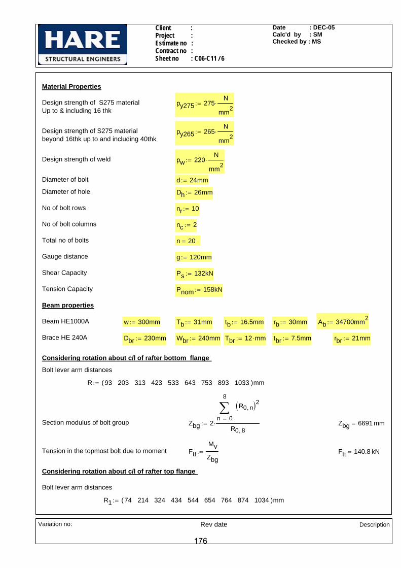
Client : Project : Estimate no : Contract no : Sheet no : C06-C11 / 6
Date : DEC-05Calc'd by : SMChecked by : MS
Beam HE1000A w 300mm:= Tb 31mm:= tb 16.5mm:= rb 30mm:= Ab 34700mm2:=
Brace HE 240A Dbr 230mm:= Wbr 240mm:= Tbr 12 mm⋅:= tbr 7.5mm:= rbr 21mm:=
Considering rotation about c/l of rafter bottom flange
Bolt lever arm distances
R 93 203 313 423 533 643 753 893 1033( )mm:=
Section modulus of bolt group Zbg 20
8
n
R0 n,( )2∑=
R0 8,⋅:= Zbg 6691 mm=
Tension in the topmost bolt due to moment FttMvZbg
:= Ftt 140.8 kN=
Considering rotation about c/l of rafter top flange
Bolt lever arm distances
R1 74 214 324 434 544 654 764 874 1034( )mm:=
Material Properties
Design strength of S275 materialUp to & including 16 thk
py275 275N
mm2⋅:=
Design strength of S275 materialbeyond 16thk up to and including 40thk
py265 265N
mm2⋅:=
Design strength of weld pw 220N
mm2⋅:=
Diameter of bolt d 24mm:=
Diameter of hole Dh 26mm:=
No of bolt rows nr 10:=
No of bolt columns nc 2:=
Total no of bolts n 20=
Gauge distance g 120mm:=
Shear Capacity Ps 132kN:=
Tension Capacity Pnom 158kN:=
Beam properties
Variation no: Rev date Description
176
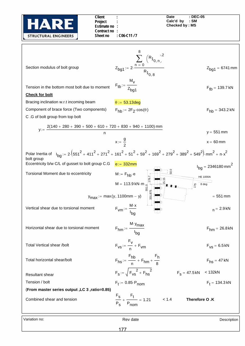
Client : Project : Estimate no : Contract no : Sheet no : C06-C11 / 7
Date : DEC-05Calc'd by : SMChecked by : MS
ymax 551 mm=
Vertical shear due to torsional moment FvmM x⋅Ibg
:= Fvm 2.9 kN=
Horizontal shear due to torsional moment FhmM ymax⋅
Ibg:= Fhm 26.8kN=
Total Vertical shear /bolt FvsFvn
Fvm+:= Fvs 6.5 kN=
Total horizontal shear/bolt FhsFhb
nFhm+
Fh8
+:= Fhs 47 kN=
Fs Fvs2 Fhs
2+:= Fs 47.5kN= < 132kNResultant shear
Tension / bolt Ft 0.85 Pnom⋅:= Ft 134.3 kN=
(From master series output ,LC 3 ,ratio=0.85)
Combined shear and tensionFsPs
FtPnom
+ 1.21= < 1.4 Therefore O .K
Section modulus of bolt group Zbg1 20
8
n
R10 n,⎛⎝
⎞⎠
2∑=
R10 8,
⋅:= Zbg1 6741 mm=
FtbMv
Zbg1:=Tension in the bottom most bolt due to moment Ftb 139.7 kN=
Check for bolt
Bracing inclination w.r.t incoming beam θ 53.13deg:=
Component of brace force (Two components) Fhb 2F2 cos θ( )⋅:= Fhb 343.2 kN=
C .G of bolt group from top bolt
y2 140 280+ 390+ 500+ 610+ 720+ 830+ 940+ 1100+( ) mm
n:= y 551 mm=
xg2
:= x 60 mm=
Polar Inertia of bolt group
Ibg 2 5512 4112+ 2712
+ 1612+ 512
+ 592+ 1692
+ 2792+ 3892
+ 5492+( )⋅ mm2
⋅ n x2⋅+:=
HE 1000A
8 deg
551.
033
1.87
5
50.0
176.
7
15.1
5
175
Eccentricity b/w C/L of gusset to bolt group C.G e 332mm:= Ibg 2346180 mm2=
Torsional Moment due to eccentricity M Fhb e⋅:=
M 113.9 kN m⋅=
ymax max y 1100mm y−,( ):=
Variation no: Rev date Description
177

Client : Project : Estimate no : Contract no : Sheet no : C06-C11 / 8
Date : DEC-05Calc'd by : SMChecked by : MS
Rs1 FL2 FTt
1.25
⎛⎜⎝
⎞
⎠
2
+:= Rs1 2.187kNmm
=
Weld size required sreqdRs1
0.7 pw⋅:= sreqd 14.20 mm=
Provide 15mm CFW between beam top flange and end plate
Weld between bottom flange and end plate
Max Compression per mm FTbC1
Lweld:= FTb 2.739
kNmm
=
Shear per mm on weld FL
Fh
2
Lweld:= FL 0.024
kNmm
=
Resultant force per mm on weld Rs2 FL2 FTb
1.25
⎛⎜⎝
⎞
⎠
2
+:= Rs2 2.192kNmm
=
Weld size required sreqdRs2
0.7 pw⋅:= sreqd 14.23 mm=
Provide 15mm CFW between beam bottom flange and end plate
Check for welds
Compression due to axial force on rafter flange
Cb1Tb w⋅
AbF⋅:= Cb1 102.9 kN=
Total compression in top flange due to major axis moment and axial
C 2 Ftb⋅0
8
n
R10 n,∑=
⎛⎜⎜⎝
⎞
⎠R10 8,
⋅ Cb1 cos 8deg( )⋅+:= C 1430.7 kN=
Total compression in bottom flange due to major axis moment and axial
C1 2 Ftt⋅0
8
n
R0 n,∑=
⎛⎜⎜⎝
⎞
⎠R0 8,
⋅ Cb1 cos 8 deg⋅( )⋅+:= C1 1434 kN=
Length available for weld Lweld 2w tb− 2 rb⋅−:= Lweld 523.5 mm=
Weld between top flange and end plate
Max Compression per mm FTtC
Lweld:= FTt 2.733
kNmm
=
Shear per mm on weld FL
Fh
2
Lweld:= FL 0.024
kNmm
=
Resultant force per mm on weld
Variation no: Rev date Description
178

Client : Project : Estimate no : Contract no : Sheet no : C06-C11 / 9
Date : DEC-05Calc'd by : SMChecked by : MS
FhsfFa6
Fhmf+:= Fhs 47 kN=
Fsf Fvsf2 Fhsf
2+:= Fsf 49.6kN= < 91.9kNResultant shear
Therefore O .K
Check for bearing capacity of incoming beam web (IPE 300)
Thickness of web twi 7.1mm:=
Dia of bolt used dbf 20mm:=
No of bolts used to connect finplate andincoming beam
nbi 6:=
Bearing strength pb275 460N
mm2:=
Shear / bolt due to incoming beam axial FsiFanbi
:= Fsi 25.8kN=
Bearing capacity of incoming beam web Pbi dbf twi⋅ pb275⋅:= Pbi 65.3kN= > 25.8kN Therefore o.k.
Checks for Finplate /End plate connection
C .G of bolt group from top bolt
y2 70 140+( ) mm
6:= y 70 mm=
x50mm
2:= x 25 mm=
Polar Inertia of bolt group
Ibgf 4 702⋅ 6 252
⋅+( ) mm2⋅:= Ibgf 23350 mm2
=
Eccentricity b/w C/L of end plate to fin/end plate bolt group C.G
ef 245mm:=
Torsional Moment due to eccentricity Mf Fv1 ef⋅:= Mf 7.4 kN m⋅=
Vertical shear due to torsional moment FvmfMf x⋅
Ibgf:= Fvmf 7.9 kN=
Horizontal shear due to torsional moment FhmfMf y⋅
Ibgf:= Fhmf 22 kN=
Total Vertical shear /bolt FvsfFv16
Fvmf+:= Fvsf 12.9kN=
Total horizontal shear/bolt
Variation no: Rev date Description
179
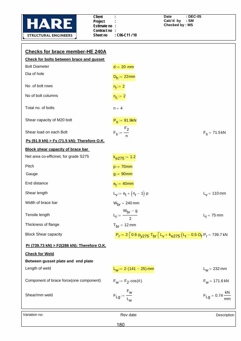
Client : Project : Estimate no : Contract no : Sheet no : C06-C11 / 10
Date : DEC-05Calc'd by : SMChecked by : MS
et 40mm:=
Shear length Lv et nr 1−( ) p⋅+:= Lv 110 mm=
Width of brace bar Wbr 240 mm=
Tensile length LtWbr g−
2:= Lt 75 mm=
Thickness of flange Tbr 12 mm=
Block Shear capacity Pr 2 0.6 py275⋅ Tbr⋅ Lv ke275 Lt 0.5 Dh⋅−( )⋅+⎡⎣ ⎤⎦⋅⎡⎣ ⎤⎦⋅:= Pr 739.7 kN=
Pr (739.73 kN) > F2(286 kN): Therefore O.K.
Check for Weld
Between gusset plate and end plate
Length of weld Lw 2 141 25−( )⋅ mm:= Lw 232 mm=
Component of brace force(one component) Fw F2 cos θ( )⋅:= Fw 171.6 kN=
Shear/mm weld FLgFwLw
:= FLg 0.74kNmm
=
Checks for brace member-HE 240ACheck for bolts between brace and gusset
Bolt Diameter d 20 mm⋅:=
Dia of holeDh 22mm:=
No .of bolt rows nr 2:=
No of bolt columns nc 2:=
Total no. of bolts n 4=
Shear capacity of M20 bolt Ps 91.9kN:=
Shear load on each Bolt FsF2n
:= Fs 71.5kN=
Ps (91.9 kN) > Fs (71.5 kN): Therefore O.K.
Block shear capacity of brace bar
Net area co-efficinet, for grade S275 ke275 1.2:=
Pitch p 70mm:=
Gauge g 90mm:=
End distance
Variation no: Rev date Description
180

Client : Project : Estimate no : Contract no : Sheet no : C06-C11 / 11
Date : DEC-05Calc'd by : SMChecked by : MS
Therefore O.K
> 286 kNPc 429.3 kN=Pc wd tg⋅ pc⋅:=Compression capacity of the plate
( B.S 5950-2000,Cl - 4.7.4 & TABLE 24)pc 167.5N
mm2=
λyy 86.6=λyy 1.5Leffryy
⋅:=Slenderness ratio
ryy 4.33mm=ryytg
2
12:=Min radius of gyration
Leff 250mm:=Max Effective length for Buckling
wd 170.8 mm=wd 2p tan 30deg( )⋅ g+:=Dispersion width
p 70mm:=Pitch
g 90mm:=Gauge
tg 15mm:=Thickness of gusset plate
Check for Gusset
By inspection ,6CFW is o.k
Between gusset plate and rafter web
Adopt 6mm CFW
s 4.8 mm=sFLg
0.7 pw⋅:=Size of weld required
Variation no: Rev date Description
181
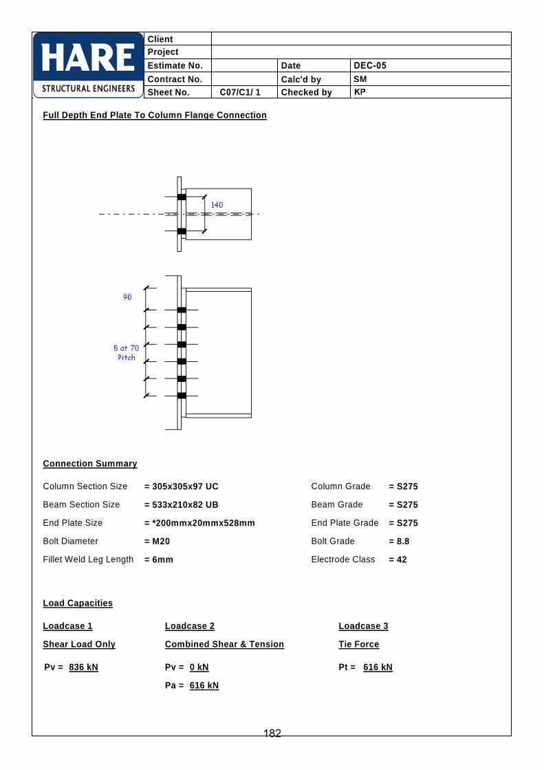
= 8.8
ClientProjectEstimate No.Contract No.Sheet No.
Date DEC-05Calc'd byChecked by C07/C1/ 1
SM
Full Depth End Plate To Column Flange Connection
Connection Summary
Column Section Size
Beam Section Size
End Plate Size
Bolt GradeBolt Diameter
Fillet Weld Leg Length
Column Grade
Beam Grade
End Plate Grade
Electrode Class
= 305x305x97 UC
= M20
= *200mmx20mmx528mm
= 533x210x82 UB
= 6mm = 42
= S275
= S275
= S275
Load Capacities
Shear Load Only Combined Shear & Tension Tie Force
836 kNPv = 0 kNPv =
616 kNPa =
616 kNPt =
Loadcase 1 Loadcase 2 Loadcase 3
182

= 8.8
ClientProjectEstimate No.Contract No.Sheet No.
Date DEC-05Calc'd byChecked by C07/C2/ 1
SM
Partial Depth End Plate To Beam Connection
Connection Summary
Support Beam Section Size
Incoming Beam Section Size
End Plate Size
Bolt GradeBolt Diameter
Fillet Weld Leg Length
Support Beam Grade
Incoming Beam Grade
End Plate Grade
Electrode Class
= 533x210x82 UB
= M20
= 160mmx20mmx360mm
= 457x191x67 UB
= 6mm = 42
= S275
= S275
= S275
Load Capacities
Shear Load Only Combined Shear & Tension Tie Force
454 kNPv = 0 kNPv =
51 kNPa =
60 kNPt =
Loadcase 1 Loadcase 2 Loadcase 3
183

ClientProjectEstimate No.Contract No.Sheet No.
Date DEC-05Calc'd byChecked by C07/C3/ 1
SM
Fin Plate To Column Flange Connection
Connection Summary
Column Section Size
Beam Section Size
Fin Plate Size
Bolt Grade = 8.8Bolt Diameter
Fillet Weld Leg Length
Column Grade
Beam Grade
Fin Plate Grade
Electrode Class
= 305x305x97 UC
= M20
= *100mmx10mm
= 533x210x82 UB
= 6mm = 42
= S275
= S275
= S275
Load Capacities
Shear Load Only Combined Shear & Tension Tie Force
451 kNPv = 0 kNPv =
529 kNPa =
529 kNPt =
Loadcase 1 Loadcase 2 Loadcase 3
x430mm Lg
184

ClientProjectEstimate No.Contract No.Sheet No.
Date DEC-05Calc'd byChecked by C07/C4/ 1
SM
Fin Plate To Column Web Connection
Connection Summary
Column Section Size
Beam Section Size
Fin Plate Size
Bolt Grade = 8.8Bolt Diameter
Fillet Weld Leg Length
Column Grade
Beam Grade
Fin Plate Grade
Electrode Class
= 533x210x82 UB
= M20
= *100mmx10mm
= 305x305x97 UC
= 6mm = 42
= S275
= S275
= S275
Load Capacities
Shear Load Only Combined Shear & Tension Tie Force
186 kNPv = 0 kNPv =
49 kNPa =
59 kNPt =
Loadcase 1 Loadcase 2 Loadcase 3
x220mm Lg
185
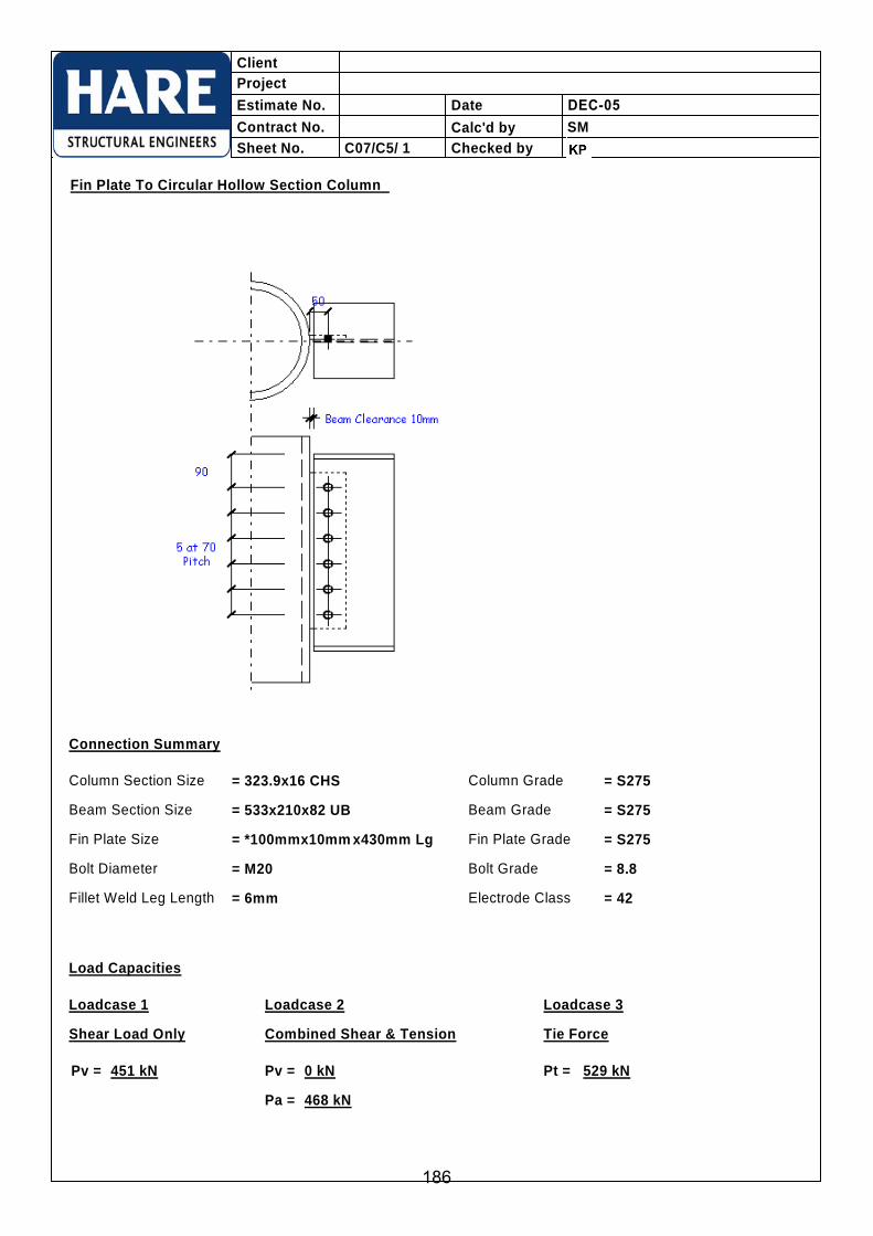
ClientProjectEstimate No.Contract No.Sheet No.
Date DEC-05Calc'd byChecked byC07/C5/ 1
SM
Fin Plate To Circular Hollow Section Column
Connection Summary
Column Section Size
Beam Section Size
Fin Plate Size
Bolt Grade = 8.8Bolt Diameter
Fillet Weld Leg Length
Column Grade
Beam Grade
Fin Plate Grade
Electrode Class
= 323.9x16 CHS
= M20
= *100mmx10mm
= 533x210x82 UB
= 6mm = 42
= S275
= S275
= S275
Load Capacities
Shear Load Only Combined Shear & Tension Tie Force
451 kNPv = 0 kNPv =
468 kNPa =
529 kNPt =
Loadcase 1 Loadcase 2 Loadcase 3
x430mm Lg
186

= 8.8
ClientProjectEstimate No.Contract No.Sheet No.
Date DEC-05Calc'd byChecked byC07/C6/ 1
SM
Fin Plate Beam To Beam Connection
Connection Summary
Support Beam Section Size
Incoming Beam Section Size
Fin Plate Size
Bolt GradeBolt Diameter
Fillet Weld Leg Length
Support Beam Grade
Incoming Beam Grade
Fin Plate Grade
Electrode Class
= 533x210x82 UB
= M20
= *100mmx10mmx360mm Lg
= 457x191x67 UB
= 6mm = 42
= S275
= S275
= S275
Load Capacities
Shear Load Only Combined Shear & Tension Tie Force
318 kNPv = 0 kNPv =
167 kNPa =
199kNPt =
Loadcase 1 Loadcase 2 Loadcase 3
Skew Angle of Beam on Plan = 90°
187

= 8.8
ClientProjectEstimate No.Contract No.Sheet No.
Date DEC-05Calc'd byChecked byC07/C7/ 1
SM
Welded Tee Beam To Beam Connection
Connection Summary
Support Beam Section Size
Incoming Beam Section Size
End Plate Size
Bolt GradeBolt Diameter
End Plate F. W. Leg Length
Support Beam Grade
Incoming Beam Grade
End Plate Grade
Electrode Class
= 533x210x82 UB
= M20
= 160mmx20mm × 453mm Lg
= 457x191x67 UB
= 6mm = 42
= S275
= S275
= S275
Load Capacities
Shear Load Only Combined Shear & Tension Tie Force
459 kNPv = 0 kNPv =
549 kNPa =
654kNPt =
Loadcase 1 Loadcase 2 Loadcase 3
Slope of Beam from Vertical = 90°
Toe Plate Size = 160mmx20mm × 501mm Lg Toe/Spade Plate Grade = S275
= *120mmx10mm × 501mm LgSpade Plate °/of
Tee Bracket F. W. Leg Length = 6mm
188

Client : Project : Estimate no: Contract no: Sheet no :C08-C1 / 1
Date : DEC-05Calc'd by : KPChecked by : SM
All main steel and fittings are S275.
All welds are 6mm CFW.
All bolts are M20. Grade 8.8.
NOTES:-
UB 254x146x37UB
254x
146x
37
8 THK PLATE WELDED TO WEB
70 x 15 THK STIFFENER PLATES (10 x10 SNIPES)
5080
80
20(M
IN)
(8 CFW)
220 x 15 THK END PLATEBOLTS @ 120 X / CRS
Mv 10kN m⋅:=Major axis moment
Fx 10kN:=Axial force
Fh 10kN:=Horizontal Shear
Fv 35kN:=Vertical Shear
LOADS :-
UB 254x146x37INCOMING BEAM
CONNECTION - C08-C1
Variation no: Rev date
Description
189

Client : Project : Estimate no: Contract no: Sheet no :C08-C1 / 2
Date : DEC-05Calc'd by : KPChecked by : SM
Dh 22mm:=
No of bolt rows nr 3:=
No of bolt columns nc 2:=
Total no of bolts n 6:=
Bolt pitch p 80mm:=
Gauge distance g 120mm:=
Shear Capacity of bolt Ps 91.9kN:=
Tension Capacity of bolt Pnom 110kN:=
Considering rotation about c/l of beam bottom flange
R 40.5 120.5 200.5( )mm:=Bolt lever arm distances
Section modulus of bolt group Zbg 20
2
n
R0 n,( )2∑=
R0 2,⋅:= Zbg 562 mm=
Tension in the topmost bolt due to moment FttMvZbg
:= Ftt 17.79 kN=
Section properties
Stub UB 254x146x37 Dc 256mm:= wc 146.4mm:= Tc 10.9mm:= tc 6.3mm:= rc 7.6mm:=
Beam UB 254x146x37 Db 256mm:= wb 146.4mm:= Tb 10.9mm:= tb 6.3mm:= rb 7.6mm:= Ab 4720mm2:=
Material Properties
Design strength of S275 materialUp to & including 16 thk
py275 275N
mm2⋅:=
Design strength of S275 materialbeyond 16thk up to and including 40thk
py265 265N
mm2⋅:=
Design strength of weld pw 220N
mm2⋅:=
Check for bolt b/w end plate and stub web
Diameter of bolt d 20mm:=
Diameter of hole
Variation no: Rev date
Description
190
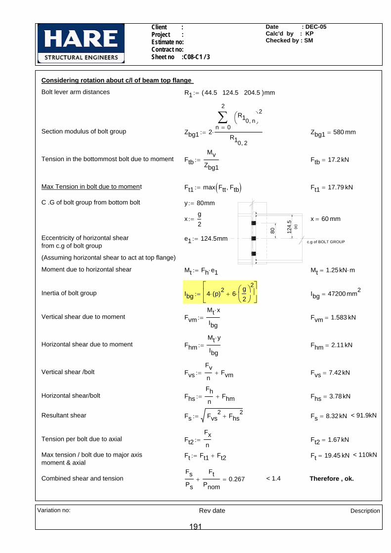
Client : Project : Estimate no: Contract no: Sheet no :C08-C1 / 3
Date : DEC-05Calc'd by : KPChecked by : SM
FvmMt x⋅
Ibg:= Fvm 1.583 kN=
Horizontal shear due to moment FhmMt y⋅
Ibg:= Fhm 2.11kN=
Vertical shear /bolt FvsFvn
Fvm+:= Fvs 7.42kN=
Horizontal shear/bolt FhsFhn
Fhm+:= Fhs 3.78kN=
Resultant shear Fs Fvs2 Fhs
2+:= Fs 8.32kN= < 91.9kN
Tension per bolt due to axial Ft2Fxn
:= Ft2 1.67kN=
Max tension / bolt due to major axis moment & axial
Ft Ft1 Ft2+:= Ft 19.45 kN= < 110kN
Combined shear and tensionFsPs
FtPnom
+ 0.267= < 1.4 Therefore , ok.
Considering rotation about c/l of beam top flange
Bolt lever arm distances R1 44.5 124.5 204.5( )mm:=
Section modulus of bolt group Zbg1 20
2
n
R10 n,⎛⎝
⎞⎠
2∑=
R10 2,
⋅:= Zbg1 580 mm=
Tension in the bottommost bolt due to moment FtbMv
Zbg1:= Ftb 17.2kN=
Max Tension in bolt due to moment Ft1 max Ftt Ftb,( ):= Ft1 17.79 kN=
124.
5
c.g of BOLT GROUP
80
(e)
C .G of bolt group from bottom bolt y 80mm:=
xg2
:= x 60 mm=
Eccentricity of horizontal shearfrom c.g of bolt group
e1 124.5mm:=
(Assuming horizontal shear to act at top flange)
Moment due to horizontal shear Mt Fh e1⋅:= Mt 1.25kN m⋅=
Inertia of bolt group Ibg 4 p( )2⋅ 6g2
⎛⎜⎝
⎞⎠
2⋅+
⎡⎢⎣
⎤⎥⎦
:= Ibg 47200 mm2=
Vertical shear due to moment
Variation no: Rev date
Description
191

Client : Project : Estimate no: Contract no: Sheet no :C08-C1 / 4
Date : DEC-05Calc'd by : KPChecked by : SM
Ft2 12.36 kN=
Moment due to bolt force MFt22
g2
tb2
− 0.8 sw⋅−⎛⎜⎝
⎞
⎠⋅:= M 0.322 kN m⋅=
Dispersion length ld p:=
Thickness of plate required treqdM 6⋅
py275 ld⋅:= treqd 9.37mm=
Adopt 15mm thk end plate
Check for weld between beam flanges and end plate
Max. compression in bottom flangeof beam due to moment Fc 2 Ftt⋅
0
2
n
R0 n,( )∑=
⎡⎢⎢⎣
⎤⎥⎥⎦
R0 2,⋅:= Fc 64.14 kN=
Effective width of beam flange b1 wb:= b1 146.4 mm=
Effective C/S area of beam Abeff Ab:= Abeff 4720 mm2=
Compressive force on beam top flange due to axial in beam
Fcab1 Tb⋅
AbeffFx⋅:= Fca 3.38kN=
Total compression in top flange C Fc Fca+:= C 67.52 kN=
Check for weld between beam web and end plate
Tension in second row of bolt Ft2Fxn
FttR0 2,
R0 1,⋅+:= Ft2 12.36 kN=
Dispersion length on weld Ld p:= Ld 80 mm=
Length of weld Lweld Ld:=
Tension per mm on weld FTFt2
Lweld:= FT 0.154
kNmm
=
Vertical shear per mm FLFv
2 Db 2 Tb⋅− 2 rb⋅−( )⋅:= FL 0.080
kNmm
=
Resultant force per mm R1FT
1.25
⎛⎜⎝
⎞
⎠
2
FL2
+:= R1 0.147kNmm
=
Size of fillet weld required sreqR1
0.7 pw⋅:= sreq 0.96mm=
Adopt 6mm CFW sw 6mm:=
Check for end plate (Worst case)
Bolt tension
Variation no: Rev date
Description
192
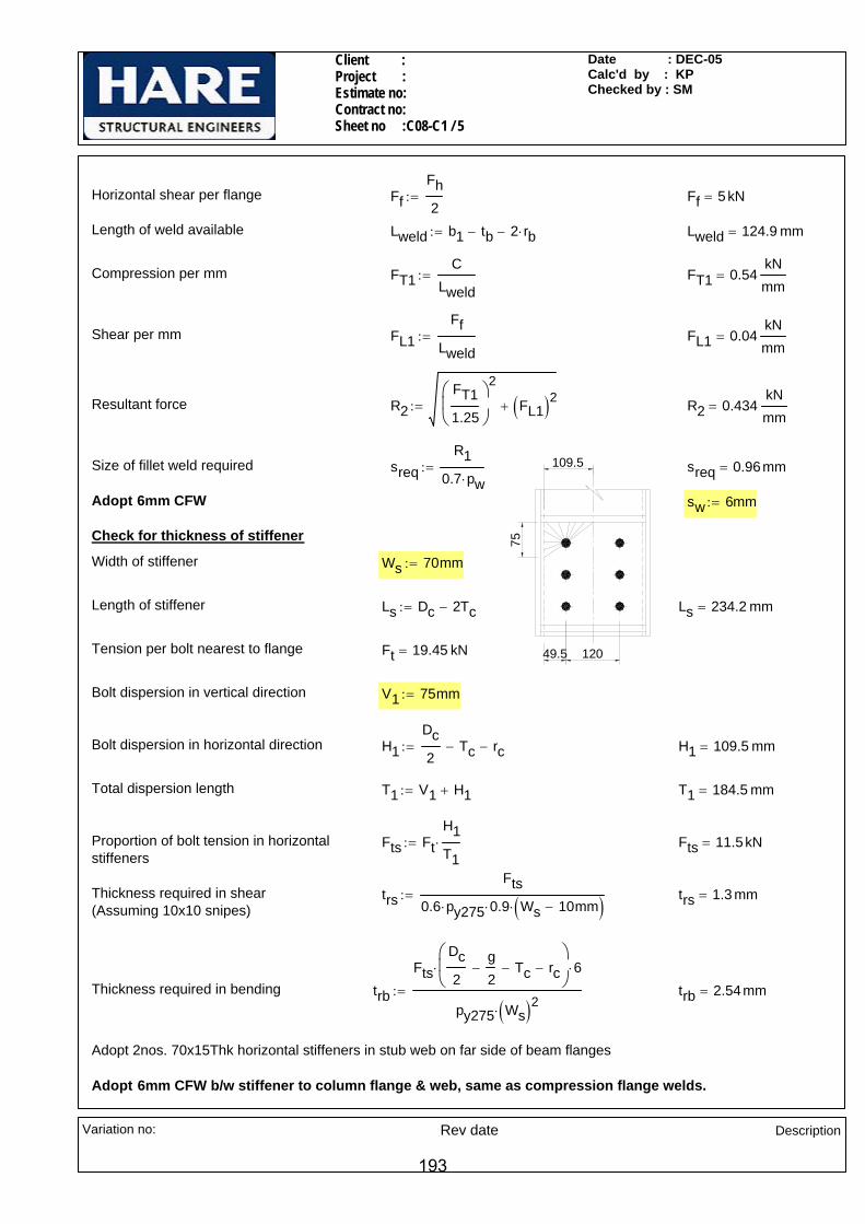
Client : Project : Estimate no: Contract no: Sheet no :C08-C1 / 5
Date : DEC-05Calc'd by : KPChecked by : SM
Ls Dc 2Tc−:= Ls 234.2 mm=
Tension per bolt nearest to flange Ft 19.45 kN=
Bolt dispersion in vertical direction V1 75mm:=
Bolt dispersion in horizontal direction H1Dc2
Tc− rc−:= H1 109.5 mm=
Total dispersion length T1 V1 H1+:= T1 184.5 mm=
Proportion of bolt tension in horizontal stiffeners
Fts FtH1T1⋅:= Fts 11.5kN=
Thickness required in shear trsFts
0.6 py275⋅ 0.9⋅ Ws 10mm−( )⋅:= trs 1.3 mm=
(Assuming 10x10 snipes)
Thickness required in bending trb
FtsDc2
g2
− Tc− rc−⎛⎜⎝
⎞
⎠⋅ 6⋅
py275 Ws( )2⋅:= trb 2.54mm=
Adopt 2nos. 70x15Thk horizontal stiffeners in stub web on far side of beam flanges
Adopt 6mm CFW b/w stiffener to column flange & web, same as compression flange welds.
Horizontal shear per flange FfFh2
:= Ff 5 kN=
Length of weld available Lweld b1 tb− 2 rb⋅−:= Lweld 124.9 mm=
Compression per mm FT1C
Lweld:= FT1 0.54
kNmm
=
Shear per mm FL1Ff
Lweld:= FL1 0.04
kNmm
=
Resultant force R2FT11.25
⎛⎜⎝
⎞
⎠
2
FL1( )2+:= R2 0.434kNmm
=
12049.5
75
109.5Size of fillet weld required sreqR1
0.7 pw⋅:= sreq 0.96mm=
Adopt 6mm CFW sw 6mm:=
Check for thickness of stiffener
Width of stiffener Ws 70mm:=
Length of stiffener
Variation no: Rev date
Description
193
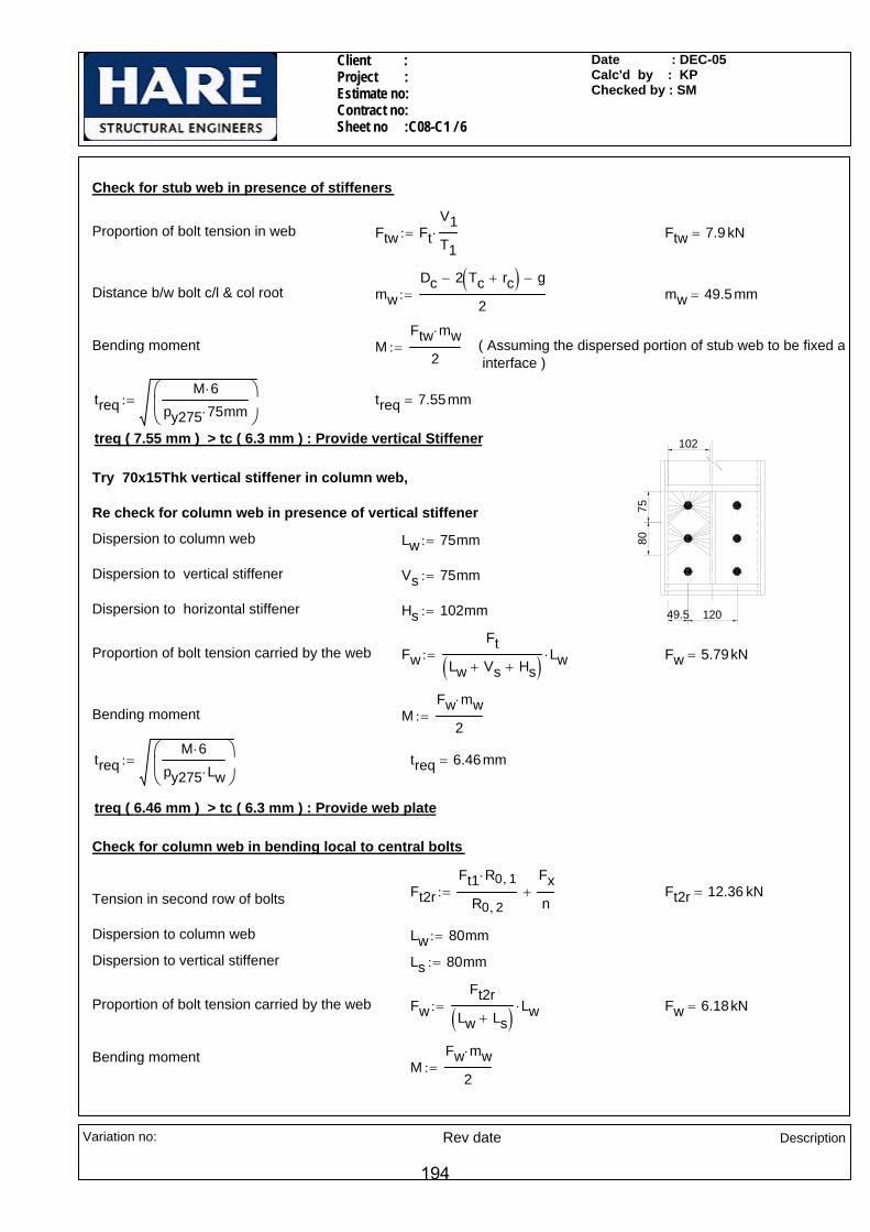
Client : Project : Estimate no: Contract no: Sheet no :C08-C1 / 6
Date : DEC-05Calc'd by : KPChecked by : SM
Proportion of bolt tension carried by the web FwFt
Lw Vs+ Hs+( ) Lw⋅:= Fw 5.79kN=
Bending moment MFw mw⋅
2:=
treqM 6⋅
py275 Lw⋅⎛⎜⎝
⎞
⎠:= treq 6.46mm=
treq ( 6.46 mm ) > tc ( 6.3 mm ) : Provide web plate
Check for column web in bending local to central bolts
Ft2rFt1 R0 1,⋅
R0 2,
Fxn
+:= Ft2r 12.36 kN=Tension in second row of bolts
Dispersion to column web Lw 80mm:=
Dispersion to vertical stiffener Ls 80mm:=
Proportion of bolt tension carried by the web FwFt2r
Lw Ls+( ) Lw⋅:= Fw 6.18kN=
Bending momentM
Fw mw⋅
2:=
Check for stub web in presence of stiffeners
Proportion of bolt tension in web Ftw FtV1T1⋅:= Ftw 7.9 kN=
Distance b/w bolt c/l & col root mwDc 2 Tc rc+( )− g−
2:= mw 49.5mm=
Bending moment MFtw mw⋅
2:= ( Assuming the dispersed portion of stub web to be fixed a
interface )
treqM 6⋅
py275 75⋅ mm⎛⎜⎝
⎞
⎠:= treq 7.55mm=
treq ( 7.55 mm ) > tc ( 6.3 mm ) : Provide vertical Stiffener 102
75
12049.5
80
Try 70x15Thk vertical stiffener in column web,
Re check for column web in presence of vertical stiffener
Dispersion to column web Lw 75mm:=
Dispersion to vertical stiffener Vs 75mm:=
Dispersion to horizontal stiffener Hs 102mm:=
Variation no: Rev date
Description
194

Client : Project : Estimate no: Contract no: Sheet no :C08-C1 / 7
Date : DEC-05Calc'd by : KPChecked by : SM
Adopt 8mm thick web plate
twp 6.61mm=twp treq2 tc
2−:=Thickness of web plate required
treq 9.13mm=treqM 6⋅
py275 80⋅ mm⎛⎜⎝
⎞
⎠:=
MFt2r mw⋅
2:=Bending moment
mw 49.5mm=Bending lever arm
Ft2r 12.36 kN=Proportion of bolt tension in web local to second bolt row
Recheck for column web (with web plate & without vertical stiffener)
Adopt 8Thk web plate in column web, O.K by inspection
twebplate 1.42mm=twebplate treq2 tc
2−:=Minimum thickness of web plate required
treq ( 6.46 mm ) > tc ( 6.3 mm ) : Provide web plate
treq 6.46mm=treqM 6⋅
py275 Lw⋅⎛⎜⎝
⎞
⎠:=
Variation no: Rev date
Description
195
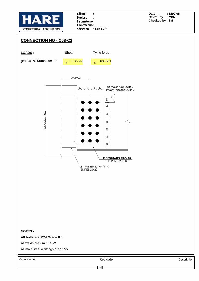
Client : Project : Estimate no : Contract no : Sheet no : C08-C2/ 1
Date : DEC-05 Calc'd by : YDN Checked by : SM
CONNECTION NO - C08-C2
LOADS : Shear Tying force
(B113) PG 600x220x106 Fv 600 kN⋅:= Fa 600 kN⋅:=
100
8080
8080
8060
60
75 75 6060 PG 600x220x81 <B111>/PG 600x220x106 <B113>
18 NOS M24 BOLTS Gr 8.8FIN PLATE 20THK
305(MAX)
305X
305X
97 U
C
STIFFENER 10THK (TYP)SNIPES 20X20
10
NOTES:-
All bolts are M24 Grade 8.8.
All welds are 6mm CFW
All main steel & fittings are S355
Variation no: Rev date Description
196

Client : Project : Estimate no : Contract no : Sheet no : C08-C2/ 2
Date : DEC-05 Calc'd by : YDN Checked by : SM
Total no of bolts n 18=
Shear capacity of bolt Ps 132kN:=
Eccentricity b/w bolt group C.G. and supporting beam web edge e 305mm:=
Torsional moment induced on bolt group due to vertical shear
MT Fv e⋅:= MT 183 kN m⋅=
Bolt group modulus Ibg 6 402⋅ 6 1202
⋅+ 6 2002⋅+ 12 752
⋅+( )mm2:= Ibg 403500 mm2
=
Max. horizontal shear on extreme bolt FhvMT 200⋅ mm
Ibg:= Fhv 90.7kN=
Max. vertical shear on extreme bolt FvvMT 75⋅ mm
Ibg
Fvn
+:= Fvv 67.3kN=
Resultant shear per bolt Fs Fhv2 Fvv
2+:= Fs 112.98 kN=
Fs ( 112.98 kN ) < Ps ( 132 kN ): Therefore O.K.
For tie force
Horizontal shear per bolt due to tie force
FhtFan
:= Fht 33.3kN=
Fht ( 33.33 kN ) < Ps ( 132 kN ): Therefore O.K.
SECTIONAL PROPERTIES
Beam (B111) PG 600x220x81
Db 600mm:= wb 220mm:= Tb 10mm:= tb 10mm:=
Column 305X305X97 UC (Worst case)
Dc 307.9mm:= wc 305.3mm:= tc 9.9mm:= Tc 15.4mm:= dc 246.7mm:=
Beam to column web connection
Check for bolt b/w fin plate to Beam web
Bolt diameter d 24 mm⋅:=
Hole diameter Dh 26 mm⋅:=
Bolt pitch p 80 mm⋅:=
Gauge g1 75mm:=
Number of bolt rows nr 6:=
Number of bolt columns nc 3:=
Variation no: Rev date Description
197

Client : Project : Estimate no : Contract no : Sheet no : C08-C2/ 3
Date : DEC-05 Calc'd by : YDN Checked by : SM
Avnet Av nr Dh⋅ tf⋅−:= Avnet 6240 mm2=
Design strength pyf 345N
mm2=
Plain shear capacity Pv 0.7 pyf⋅ Avnet⋅ Ke355⋅ Avnet0.85 Av⋅
Ke355≤if
0.6 pyf⋅ Av⋅ otherwise
:= Pv 1657.7 kN=
210
460
Block Shear capacity
Coefficient k1 if nc 1= 0.5, 1.5,( ):= kk10.6
nc 2=if
k1 1+
0.6nc 3=if
k1 nc 1=if
:= k 4.17=
Shear length Lv 460 mm⋅:=
Tensile length Lt 210 mm⋅:=
Block Shear capacity Pr1 0.6 pyf⋅ tf⋅ Lv Ke355 Lt k Dh⋅−( )⋅+⎡⎣ ⎤⎦⋅:= Pr1 2367.4 kN=
Shear capacity of fin plate Pvmin min Pv Pr1,( ):= Pvmin 1657.7 kN=
Fv ( 600 kN ) < Pvmin ( 1657.66 kN ): Therefore O.K.
Check for bearing of beam web / fin plate
Bearing strength of S355 - material
pbs355 550N
mm2:=
Thickness of fin plate tf 20mm:=
Min edge distance emin 60mm:=
Minimum thickness of connected ply t min tf tb,( ):= t 10 mm=
Bearing capacity Pbs1 min d t⋅ pbs355⋅ 0.5 emin⋅ t⋅ pbs355⋅,( ):= Pbs1 132 kN=
Fs ( 112.98 kN ) < Pbs1 ( 132 kN ): Therefore O.K.
Checks for Fin plate
For shear
Plain shear capacity
Design coefficient for S355 Ke355 1.1:=
Depth of fin plate Df 520mm:=
Area of fin plate Av 0.9Df tf⋅:= Av 9360 mm2=
Net area of fin plate
Variation no: Rev date Description
198

Client : Project : Estimate no : Contract no : Sheet no : C08-C2/ 4
Date : DEC-05 Calc'd by : YDN Checked by : SM
tf 20 mm=
tf/0.15 ( 133.33 mm ) > e ( 70 mm ) : No check needed for Long fin plate
Check for shear & bending interaction of incoming beam web section
Db 600 mm=Depth of beam
Av Db tb⋅:= Av 6000 mm2=Area of beam
Avnet Av nr Dh⋅ tb⋅−:= Avnet 4440 mm2=Net area of beam
pyb 355N
mm2=Design strength
Plain shear capacity Pvb 0.7 pyb⋅ Avnet⋅ Ke355⋅ Avnet0.85 Av⋅
Ke355≤if
0.6 pyb⋅ Av⋅ otherwise
:= Pvb 1213.7 kN=
Check for weld b/w column web to fin plate
Design strength of fillet - weld for S355 material
pw 250N
mm2⋅:=
For Bending
Distance from column web to firstline of bolt group
a 230mm:=
Eccentricity from column web to CG of bolt group
e a nc 1−( )g12
⋅+:= e 305 mm=
Moment due to eccentricity Mx Fv e⋅:= Mx 183 kN m⋅=
Section modulus of the section Zxxtf Df
2⋅
6:= Zxx 901333 mm3
=
Moment capacity in the presence of shear
McN pyf Zxx⋅ Fv 0.75 Pvmin⋅≤if
1.5 pyf⋅ Zxx⋅ 1Fv
Pvmin
⎛⎜⎜⎝
⎞
⎠
2
−
⎡⎢⎢⎣
⎤⎥⎥⎦
0.5
⋅ otherwise
:= McN 311 kN m⋅=
McN (310.96 kN) > Mx (183 kN): Therefore O.K.
For Lateral torsional buckling
Distance b/w nearest point of fixity and first column of bolt
ef 70mm:=
Thickness of fin plate
Variation no: Rev date Description
199
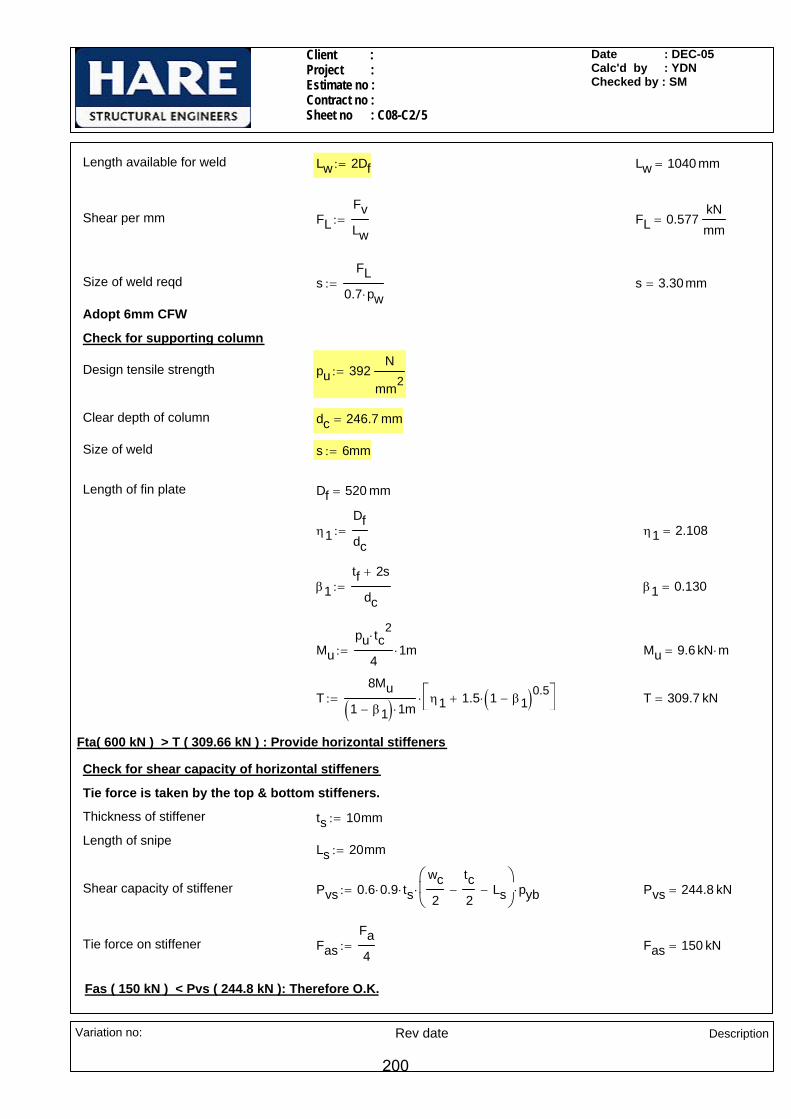
Client : Project : Estimate no : Contract no : Sheet no : C08-C2/ 5
Date : DEC-05 Calc'd by : YDN Checked by : SM
β1tf 2s+
dc:= β1 0.130=
Mupu tc
2⋅
41⋅ m:= Mu 9.6 kN m⋅=
T8Mu
1 β1−( ) 1⋅ mη1 1.5 1 β1−( )0.5
⋅+⎡⎣
⎤⎦⋅:= T 309.7 kN=
Fta( 600 kN ) > T ( 309.66 kN ) : Provide horizontal stiffeners
Check for shear capacity of horizontal stiffeners
Tie force is taken by the top & bottom stiffeners.
Thickness of stiffener ts 10mm:=
Length of snipeLs 20mm:=
Shear capacity of stiffener Pvs 0.6 0.9⋅ ts⋅wc2
tc2
− Ls−⎛⎜⎝
⎞
⎠⋅ pyb⋅:= Pvs 244.8 kN=
Tie force on stiffener FasFa4
:= Fas 150 kN=
Fas ( 150 kN ) < Pvs ( 244.8 kN ): Therefore O.K.
Length available for weld Lw 2Df:= Lw 1040 mm=
Shear per mm FLFvLw
:= FL 0.577kNmm
=
Size of weld reqd sFL
0.7 pw⋅:= s 3.30mm=
Adopt 6mm CFW
Check for supporting column
Design tensile strength pu 392N
mm2:=
Clear depth of column dc 246.7 mm=
Size of weld s 6mm:=
Length of fin plate Df 520 mm=
η1Dfdc
:= η1 2.108=
Variation no: Rev date Description
200

Client : Project : Estimate no : Contract no : Sheet no : C08-C2/ 6
Date : DEC-05 Calc'd by : YDN Checked by : SM
Check for weld b/w horizontal stiffeners & column flange
Length available for weld Lwwc2
tc2
− Ls−:= Lw 127.7 mm=
FLFas2 Lw⋅
:=Shear per mm on weld FL 0.587kNmm
=
Size of weld reqd swFL
0.7 pw⋅:= sw 3.4 mm=
Adopt 6mm CFW allround..
Variation no: Rev date Description
201
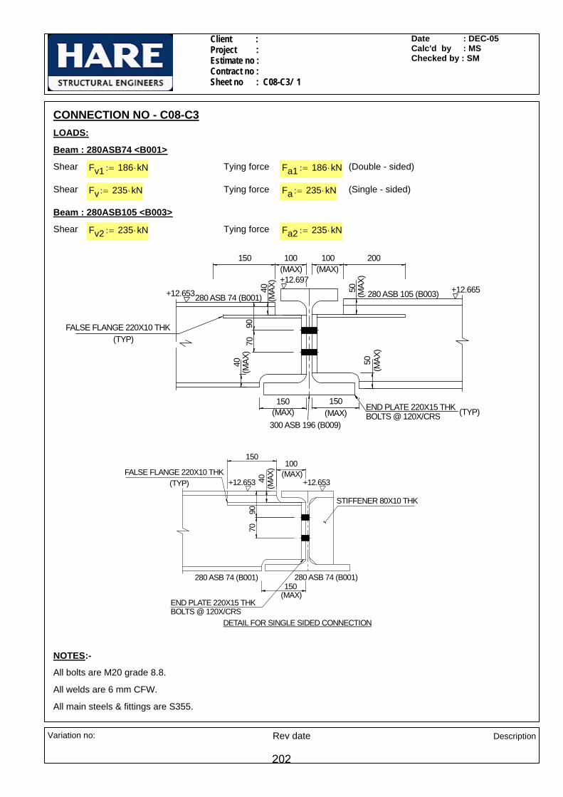
Client : Project : Estimate no : Contract no : Sheet no : C08-C3/ 1
Date : DEC-05 Calc'd by : MS Checked by : SM
All main steels & fittings are S355.
All welds are 6 mm CFW.
All bolts are M20 grade 8.8.
NOTES:-
150
40(M
AX)
9070
100
280 ASB 74 (B001) 280 ASB 74 (B001)
+12.653
END PLATE 220X15 THK BOLTS @ 120X/CRS
DETAIL FOR SINGLE SIDED CONNECTION
(MAX)
(MAX)
+12.653FALSE FLANGE 220X10 THK (TYP)
150
STIFFENER 80X10 THK
150 150(MAX)
40
9070
50 (MAX
)
100
280 ASB 105 (B003)280 ASB 74 (B001)
FALSE FLANGE 220X10 THK (TYP)
300 ASB 196 (B009)
END PLATE 220X15 THK BOLTS @ 120X/CRS (TYP)
+12.653 +12.665+12.697
40(M
AX)
(MAX
)
50(M
AX)
(MAX)
150(MAX)
100 200(MAX)
Fa2 235 kN⋅:=Tying forceFv2 235 kN⋅:=Shear
Beam : 280ASB105 <B003>
(Single - sided)Fa 235 kN⋅:=Tying forceFv 235 kN⋅:=Shear
(Double - sided)Fa1 186 kN⋅:=Tying forceFv1 186 kN⋅:=Shear
Beam : 280ASB74 <B001>
LOADS:
CONNECTION NO - C08-C3
Variation no: Rev date Description
202

Client : Project : Estimate no : Contract no : Sheet no : C08-C3/ 2
Date : DEC-05 Calc'd by : MS Checked by : SM
Ultimate tensile strength of S355 materialpu355 392
N
mm2⋅:=
Check for bolts b/w end plate & beam web for vertical shear (Worst case)
Dia of bolt d 20mm:=
No of bolt rows nr 2:=
No of bolt columns nc 2:=
Total no of bolts n 4=
Gauge distance g 120mm:=
Shear capacity of bolt Ps 91.9kN=
Tension capacity of bolt Pnom 110 kN=
Vertical shear /bolt FsFv2n
:= Fs 58.75 kN=
Ps (91.9 kN) > Fs (58.75 kN): Therefore O.K.
Check for bolts b/w end plate & beam web for tying force
Minimum pass through tension per bolt FtFa1
n:= Ft 46.5kN=
(Double sided connection)
SECTIONAL PROPERTIES
Supported beam :280ASB74(B001)
Db1 272mm:= wbt1 175mm:= wbb1 285mm:= Tb1 14mm:= tb1 10mm:= rb1 24mm:= db1 196mm:=
Ab1 9370 mm2=
Supported beam :280ASB105(B003)
Db2 288mm:= wbt2 176mm:= wbb2 286mm:= Tb2 22mm:= tb2 11mm:= rb2 24mm:= db2 196mm:=
Ab2 13340 mm2=
MATERIAL PROPERTIES
Design strength of S355 material up to & including 16 mm thk. py355 355N
mm2⋅:=
Design strength of S355 material beyond 16 mm thk and including 40 mm thk. py345 345N
mm2⋅:=
Design strength of weld pw 250N
mm2⋅:=
Variation no: Rev date Description
203

Client : Project : Estimate no : Contract no : Sheet no : C08-C3/ 3
Date : DEC-05 Calc'd by : MS Checked by : SM
Ftw 2 Ft⋅:= Ftw 93 kN=
Ptc(435.51 kN) > Ftw (93 kN): Therefore O.K.
Check for shear capacity
Shear capacity of 280 ASB 74 PvN1 0.9 0.6⋅ py355⋅ 192⋅ mm tb1⋅:= PvN1 368.06 kN=
Shear capacity of 280 ASB 105 PvN2 0.9 0.6⋅ py345⋅ 188⋅ mm tb2⋅:= PvN2 385.27 kN=
PvN2 (385.27 kN) > Fv2 (235 kN): Therefore O.K.
Check for bending capacity @ the notch 280 ASB 105 (Worst case)
Depth of web above false flange dbw 188mm:=
C.G. of notched section from top,
ytdbw
2:= yt 94 mm=
Taking second moment of area about top of false flange @ top of 280 ASB 105,
Ixn1tb2 dbw
3⋅
12:= Ixn1 6090949.33 mm4
=
Section modulus ZN1Ixn1yt
:= ZN1 64797.33 mm3=
Minimum pass through tension per bolt Ft1Fan
:= Ft1 58.75 kN=(Single sided connection)
Pnom (110 kN) > Ft1 (58.75 kN): Therefore O.K.
Check for bearing capacity of supporting beam web
Supporting beam web thickness tb 20mm:=
Bearing strength of beam web pbs 550N
mm2:=
101
107
75
105
104.5087
Bearing capacity of beam web Fb pbs d⋅ tb⋅:= Fb 220 kN=
Bearing capacity of bolts FbsFv1n
Fv2n
+:= Fbs 105.3 kN=
Fb (220 kN) > Fbs (105.25 kN): Therefore O.K.
Check for tension capacity of incoming beam web (Worst case)
Tension capacity of incoming beam web Ptc pu355 tb2⋅ 101⋅ mm:= Ptc 435.5 kN=
280 ASB 105
Tension acting on incoming beam web
Variation no: Rev date Description
204

Client : Project : Estimate no : Contract no : Sheet no : C08-C3/ 4
Date : DEC-05 Calc'd by : MS Checked by : SM
ZN1Ixn1ymax
:= ZN1 103376.71 mm3=
101
107
75
105
104.50
87
Moment capacity of the beam at the notch in the presence of shear
McN1 py345 ZN1⋅:= McN1 35.66 kN m⋅=
Moment due to shear M Fv2 150mm( )⋅:= M 35.25 kN m⋅=
(Worst case moment)
M (35.25 kN) < McN1 (35.66 kN): Therefore O.K.
Check for weld between beam web and end plate (Worst case)
Eff. shear length for weld Ls 188mm:= Ls 188 mm=
Shear per mm FLFv22 Ls⋅
:= FL 0.625kNmm
=
107Tension per mm FT
Ft1107mm
:= FT 0.549kNmm
=
Moment capacity McN ZN1 py345⋅:= McN 22.36 kN m⋅=
Moment due to shear M Fv2 100mm( )⋅:= M 23.50 kN m⋅=
McN (22.36 kN) < M (23.5 kN): Therefore FAILS
Depth of web above false flange dbw 178mm:=
Width of false flange Wf 220mm:=
Thickness of false flange tf 10mm:=
C.G. of notched section from top
178
10
11
220
yt
dbw tb2⋅dbw
2tf+
⎛⎜⎝
⎞
⎠⋅
⎡⎢⎣
⎤⎥⎦
tf Wf⋅tf2
⎛⎜⎝
⎞
⎠⋅+
dbw tb2⋅ Wf tf⋅+:= yt 49.3mm=
ymax 188mm yt−:= ymax 138.7 mm=
Taking second moment of area about top of false flange @ top of ASB 280,
Ixn1tb2 dbw
3⋅
12dbw tb2⋅
dbw2
tf+⎛⎜⎝
⎞
⎠yt−
⎡⎢⎣
⎤⎥⎦
2
⋅
⎡⎢⎢⎣
⎤⎥⎥⎦
+Wf tf
3⋅
12
⎛⎜⎜⎝
⎞
⎠+ Wf tf⋅ yt
tf2
⎛⎜⎝
⎞
⎠−
⎡⎢⎣
⎤⎥⎦
2
⋅+:= Ixn1 14342014.99 mm4=
Section modulus
Variation no: Rev date Description
205
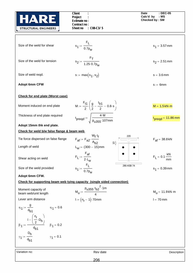
Client : Project : Estimate no : Contract no : Sheet no : C08-C3/ 5
Date : DEC-05 Calc'd by : MS Checked by : SM
Faf 38.8kN=
Length of weld Lw 300 15−( )mm:=
FLFaf
2 Lw⋅:= FL 0.1
kNmm
=Shear acting on weld
Size of the weld provided s1FL
0.7pw:= s1 0.39mm=
Adopt 6mm CFW.
Check for supporting beam web tying capacity (single sided connection)
Moment capacity of beam web/unit length Mu
pu355 tb22
⋅ 1⋅ m
4:= Mu 11.9kN m⋅=
Lever arm distance l nr 1−( ) 70⋅ mm:= l 70 mm=
η1g
db1:= η1 0.6=
β1
lnr2
Dh⋅⎛⎜⎝
⎞
⎠−
db1:= β1 0.2=
γ1Dhdb1
:= γ1 0.1=
Size of the weld for shear s1FL
0.7pw:= s1 3.57mm=
Size of the weld for tension s2FT
1.25 0.7⋅ pw:= s2 2.51mm=
Size of weld reqd. s max s1 s2,( ):= s 3.6 mm=
Adopt 6mm CFW s 6mm:=
Check for end plate (Worst case)
Moment induced on end plate MFt12
g2
tb12
− 0.8 s⋅−⎛⎜⎝
⎞
⎠⋅:= M 1.5 kN m⋅=
Thickness of end plate requiredtpreqd
4 M⋅pu355 107mm⋅
:= tpreqd 11.86 mm=
Adopt 15mm thk end plate.
Check for weld b/w false flange & beam web
10
220
280 ASB 74
Tie force dispersed on false flange Faf Fa2Wf tf⋅
Ab2⋅:=
Variation no: Rev date Description
206
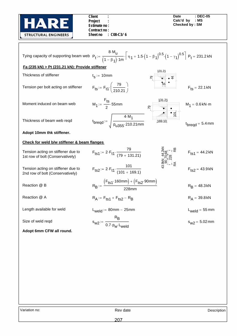
Client : Project : Estimate no : Contract no : Sheet no : C08-C3/ 6
Date : DEC-05 Calc'd by : MS Checked by : SM
Tension acting on stiffener due to 1st row of bolt (Conservatively)
Fts1 2 Ft1⋅79
79 131.21+( )⋅:= Fts1 44.2kN=
Tension acting on stiffener due to 2nd row of bolt (Conservatively)
Fts2 2 Ft1⋅101
101 169.1+( )⋅:= Fts2 43.9kN=
Reaction @ B RBFts1 160⋅ mm( ) Fts2 90⋅ mm( )+
228mm:= RB 48.3kN=
Reaction @ A RA Fts1 Fts2+ RB−:= RA 39.8kN=
Length available for weld Lweld 80mm 25mm−:= Lweld 55 mm=
Size of weld reqd sw2RB
0.7 pw⋅ Lweld⋅:= sw2 5.02mm=
Adopt 6mm CFW all round.
Tying capacity of supporting beam web Pt8 Mu⋅
1 β1−( ) 1⋅ mη1 1.5 1 β1−( )0.5
⋅ 1 γ1−( )0.5⋅+⎡
⎣⎤⎦⋅:= Pt 231.2 kN=
Fa (235 kN) > Pt (231.21 kN): Provide stiffener
79
131.21
44
55
Thickness of stiffener ts 10mm:=
Tension per bolt acting on stiffener Fts Ft179
210.21⎛⎜⎝
⎞⎠
⋅:= Fts 22.1kN=
79
131.21
101
169.10
Moment induced on beam web M1Fts2
55⋅ mm:= M1 0.6 kN m⋅=
Thickness of beam web reqd tbreqd4 M1⋅
pu355 210.21⋅ mm:= tbreqd 5.4 mm=
Adopt 10mm thk stiffener.
Check for weld b/w stiffener & beam flanges
RB
RA22
844.2
kN43
.9kN
6870
90
Variation no: Rev date Description
207
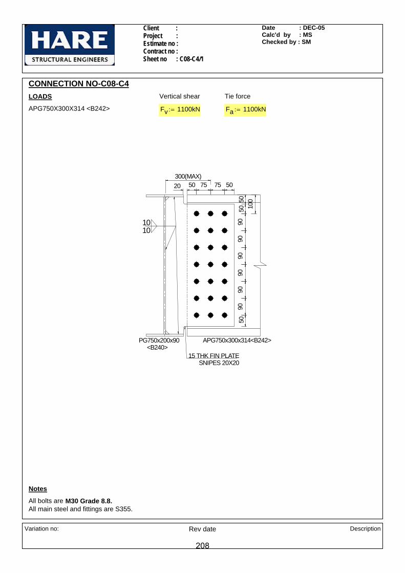
Client : Project : Estimate no : Contract no : Sheet no : C08-C4/1
Date : DEC-05Calc'd by : MSChecked by : SM
CONNECTION NO-C08-C4LOADS Vertical shear Tie force
APG750X300X314 <B242> Fv 1100kN:= Fa 1100kN:=
50 75 75 50
9090
9090
9090
15 THK FIN PLATESNIPES 20X20
APG750x300x314<B242>
20
100
PG750x200x90 <B240>
300(MAX)
5050
50
1010
Notes
All bolts are M30 Grade 8.8.All main steel and fittings are S355.
Variation no: Rev date Description
208
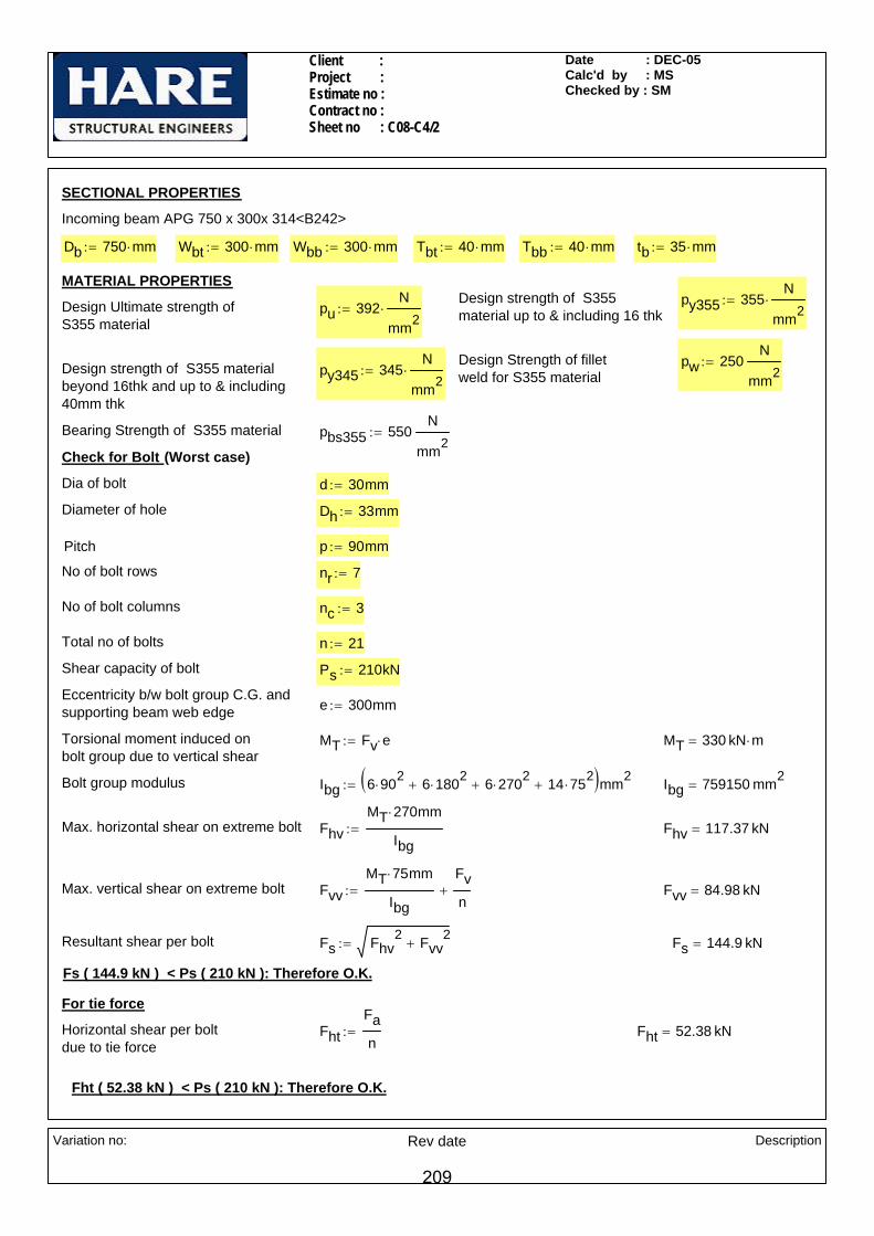
Client : Project : Estimate no : Contract no : Sheet no : C08-C4/2
Date : DEC-05Calc'd by : MSChecked by : SM
nc 3:=
Total no of bolts n 21:=
Shear capacity of bolt Ps 210kN:=
Eccentricity b/w bolt group C.G. and supporting beam web edge e 300mm:=
Torsional moment induced on bolt group due to vertical shear
MT Fv e⋅:= MT 330 kN m⋅=
Bolt group modulus Ibg 6 902⋅ 6 1802
⋅+ 6 2702⋅+ 14 752
⋅+( )mm2:= Ibg 759150 mm2
=
Max. horizontal shear on extreme bolt FhvMT 270⋅ mm
Ibg:= Fhv 117.37 kN=
Max. vertical shear on extreme bolt FvvMT 75⋅ mm
Ibg
Fvn
+:= Fvv 84.98 kN=
Resultant shear per bolt Fs Fhv2 Fvv
2+:= Fs 144.9 kN=
Fs ( 144.9 kN ) < Ps ( 210 kN ): Therefore O.K.
For tie force
Horizontal shear per bolt due to tie force
FhtFan
:= Fht 52.38 kN=
Fht ( 52.38 kN ) < Ps ( 210 kN ): Therefore O.K.
SECTIONAL PROPERTIES
Incoming beam APG 750 x 300x 314<B242>
Db 750 mm⋅:= Wbt 300 mm⋅:= Wbb 300 mm⋅:= Tbt 40 mm⋅:= Tbb 40 mm⋅:= tb 35 mm⋅:=
MATERIAL PROPERTIES Design strength of S355material up to & including 16 thk
py355 355N
mm2⋅:=Design Ultimate strength of
S355 material pu 392
N
mm2⋅:=
Design Strength of fillet weld for S355 material
pw 250N
mm2:=Design strength of S355 material
beyond 16thk and up to & including 40mm thk
py345 345N
mm2⋅:=
Bearing Strength of S355 material pbs355 550N
mm2:=
Check for Bolt (Worst case)
Dia of bolt d 30mm:=
Diameter of hole Dh 33mm:=
Pitch p 90mm:=
No of bolt rows nr 7:=
No of bolt columns
Variation no: Rev date Description
209

Client : Project : Estimate no : Contract no : Sheet no : C08-C4/3
Date : DEC-05Calc'd by : MSChecked by : SM
Pv 1340.78 kN=
Fv ( 1100 kN ) < Pv ( 1340.78 kN ): Therefore O.K.
600
200
Check for Fin plate Block Shear
For vertical shear
Shear length Lv 600 mm⋅:=
k 4.17=
Tensile length Lt 200 mm⋅:=
Block Shear Pr1 0.6 py355⋅ tf⋅ Lv Ke355 Lt k Dh⋅−( )⋅+⎡⎣ ⎤⎦⋅:= Pr1 2136.66 kN=
550
200
Fv ( 1100 kN ) < Pr1 ( 2136.66 kN ): Therefore O.K.
For tie force
Shear length Lv1 200 mm⋅:=
k1 10:=
Tensile length Lt1 550 mm⋅:=
Block Shear Pr2 0.6 py355⋅ tf⋅ 2 Lv1⋅ Ke355 Lt1 k1 Dh⋅−( )⋅+⎡⎣ ⎤⎦⋅:= Pr2 2051.19 kN=
Fa ( 1100 kN ) < Pr2 ( 2051.19 kN ): Therefore O.K.
Check for bearing of beam web / fin plate
Thickness of fin plate tf 15mm:=
Minimum end distance e 50mm:=
Minimum thickness of connected ply t min tf tb,( ):= t 15 mm=
Bearing capacity Pbs1 min d t⋅ pbs355⋅ 0.5 e⋅ t⋅ pbs355⋅,( ):= Pbs1 206.25 kN=
Fvv ( 84.98 kN ) < Pbs1 ( 206.25 kN ): Therefore O.K.
Check for Fin plate Plain Shear capacity
Design coefficient for S355 Ke355 1.1:=
Depth of fin plate Dwf 620mm:=
Area of fin plate Av 0.9Dwf tf⋅:= Av 8370 mm2=
Net area of fin plate Avnet Av nr Dh⋅ tf⋅−:= Avnet 4905 mm2=
Plain shear capacity Pv 0.7 py355⋅ Avnet⋅ Ke355⋅ Avnet0.85 Av⋅
Ke355≤if
0.6 py355⋅ Av⋅ otherwise
:=
Variation no: Rev date Description
210

Client : Project : Estimate no : Contract no : Sheet no : C08-C4/4
Date : DEC-05Calc'd by : MSChecked by : SM
Shear per mm on weld FLFv
2 Lweld⋅:= FL 0.797
kNmm
=
Size of fillet weld required sreqdFL
0.7 pw⋅:= sreqd 4.55mm=
Check for weld b/w fin plate and supporting beam (For tie force)
Adopt 10mm CFW allround. (Refer PROKON output)
Check for supporting beam web
Clear depth of beam dc 714mm:=
Thickness of supporting beam web tb1 10mm:=
Size of weld s 10mm:=
Length of fin plate Df 690mm:=
η1tfdc
:= η1 0.021=
Shear and bending interaction of fin plate
Eccentricity from beam web to centre line first row bolt a 225mm:=
Moment due to eccentricity Mx Fv a⋅:= Mx 247.50 kN m⋅=
Shear capacity of fin plate Pvmin min Pv Pr1,( ):= Pvmin 1340.78 kN=
Section modulus of the section Zxxtf Dwf
2⋅
6:= Zxx 961000 mm3
=
Moment capacity in the presence of shear
McN py355 Zxx⋅ Fv 0.75 Pvmin⋅≤if
1.5 py355⋅ Zxx⋅ 1Fv
Pvmin
⎛⎜⎜⎝
⎞
⎠
2
−
⎡⎢⎢⎣
⎤⎥⎥⎦
0.5
⋅ otherwise
:= McN 292.59 kN m⋅=
McN (292.59 kN) > Mx (247.5 kN): Therefore O.K.
Fin plate is connected with supporting beam flanges also. It is assumed that the tie force was taken up by the supporting beam flanges & web together through the weld group.
Weld b/w fin plate to supporting beam web (For vertical shear)
Length available for weld Lweld 690mm:=
Variation no: Rev date Description
211
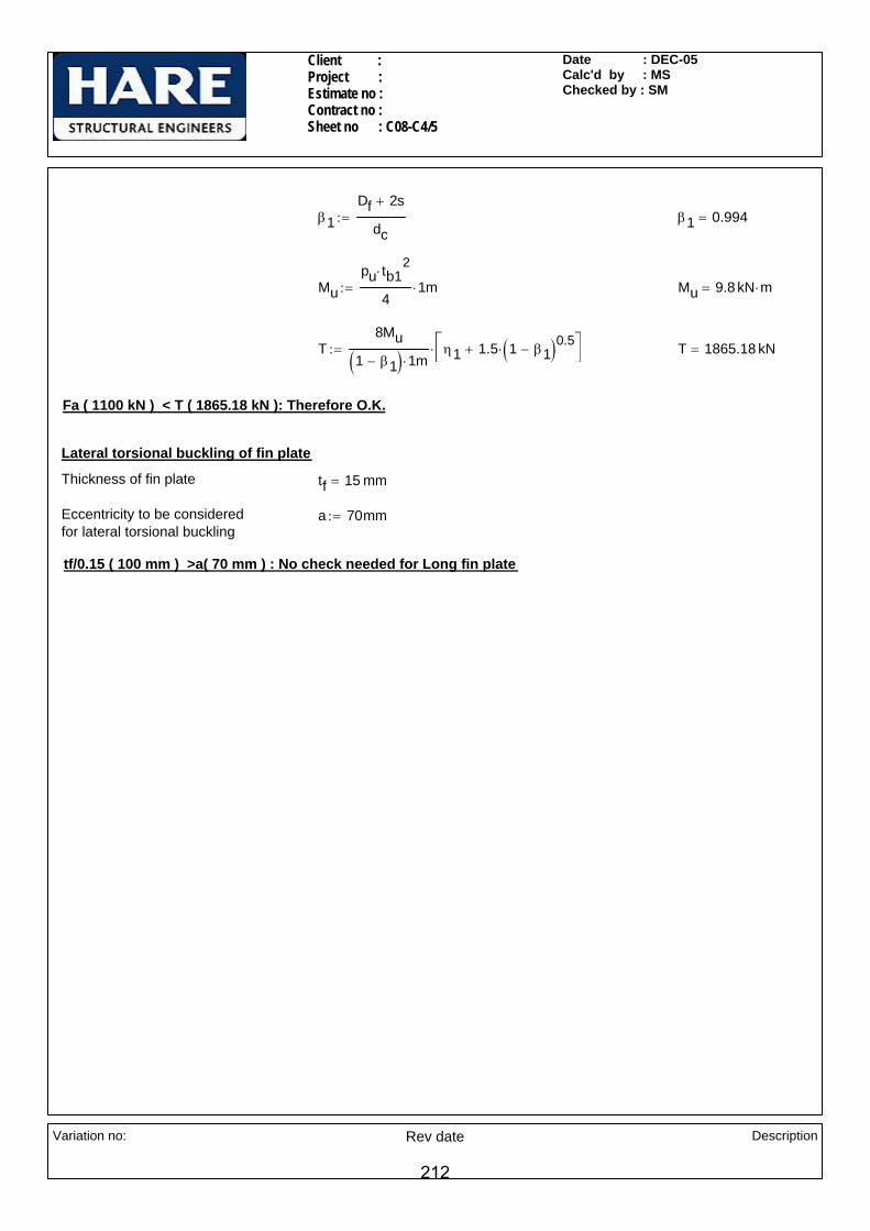
Client : Project : Estimate no : Contract no : Sheet no : C08-C4/5
Date : DEC-05Calc'd by : MSChecked by : SM
β1Df 2s+
dc:= β1 0.994=
Mupu tb1
2⋅
41⋅ m:= Mu 9.8 kN m⋅=
T8Mu
1 β1−( ) 1⋅ mη1 1.5 1 β1−( )0.5
⋅+⎡⎣
⎤⎦⋅:= T 1865.18 kN=
Fa ( 1100 kN ) < T ( 1865.18 kN ): Therefore O.K.
Lateral torsional buckling of fin plate
Thickness of fin plate tf 15 mm=
Eccentricity to be considered for lateral torsional buckling
a 70mm:=
tf/0.15 ( 100 mm ) >a( 70 mm ) : No check needed for Long fin plate
Variation no: Rev date Description
212

SheetJob Number
Job Title
Client
Calcs by Checked by SM Date
Software Consultants (Pty) LtdInternet: http://www.prokon.comE-Mail : [email protected]
C08-C4-06
MS DEC-05
Weld Group Shear Analysis Ver W2.0.00 - 05 Aug 2003 S16
InputAnalysis MethodWeld Metal Ultimate Strength (MPa)Parent Metal Ultimate Strength (MPa)Parent Metal Yield Strength (MPa)Applied ULS Force (kN)Force Angle (°)Horizontal Force Position (mm)Vertical Force Position (mm)
Linear42049035511001800345
Title : Default Connection Created: 1/3/06 9:23:39 AM
Weld Input
Code X / Radius(mm)
Y / Angle(mm)
Size(mm)
+ 0 0 10 75 0 -0 690 -75 -0
1100 kN
Since unit values are used for the length and size of the weld, the capacity of this layout is given in MPaThe capacity, Ps is the lesser of Ps1 and Ps2 : Table 36
Capacity = 1.47 kN/mm of a 10 mm weld
213

SheetJob Number
Job Title
Client
Calcs by Checked by SM Date
Software Consultants (Pty) LtdInternet: http://www.prokon.comE-Mail : [email protected]
C08-C4/07
MS DEC-05The Polar Moment of Inertia for the group = 454730826 mm^4
The Moment = -0 kNm
The Largest force on any part of the weld = 1.31 kN/mm
The maximum resistance of the Weld Group is: 1237.5 kN
The Applied ULS Force = 1100 kN
Weld is Safe
Weld Forces for Applied Load
0
1.5
3.0
4.5
6.0
7.5kN/mm
214

Client : Project : Estimate no : Contract no : Sheet no :C08-C5/ 1
Date : DEC-05Calc'd by : KPChecked by : SM
CONNECTION NO - C08-C5
LOADS: T-LOADING
HE 300A
Vertical shear Fv 150kN:=
Axial Force F 310kN:=
Horizontal shear Fh 44kN:=
160X25 THK END PLATE BOLTS @ 90 X/CRS
170
88
BO L TS @ 90 X/C R S
BO L T S @ 90 X/ CR S
1 60 X2 5 TH K EN D P LA TEB OL T S @ 9 0 X /CR S
160X20 THK TEE FLANGE PLATE
9070
70
HE300A
20 THK WEB PLATE
BOLTS @ 90 X/CRS
HE300A
Full prep., PPBW
NOTES:-
All bolts are M20, Grade 8.8
All welds are 6mm CFW U.N.O
All main steel & fittings are S275.
Variation no: Rev date Description
215
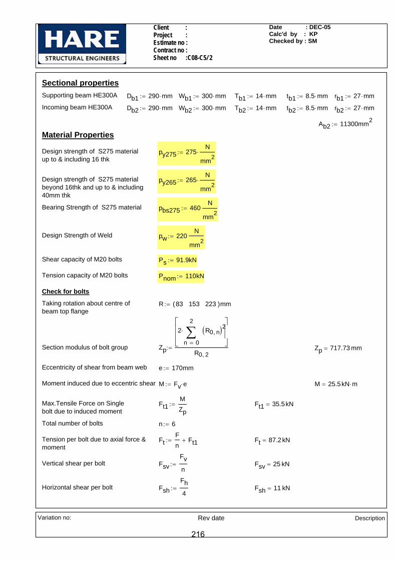
Client : Project : Estimate no : Contract no : Sheet no :C08-C5/ 2
Date : DEC-05Calc'd by : KPChecked by : SM
Sectional propertiesSupporting beam HE300A Db1 290 mm⋅:= Wb1 300 mm⋅:= Tb1 14 mm⋅:= tb1 8.5 mm⋅:= rb1 27 mm⋅:=
Incoming beam HE300A Db2 290 mm⋅:= Wb2 300 mm⋅:= Tb2 14 mm⋅:= tb2 8.5 mm⋅:= rb2 27 mm⋅:=
Ab2 11300mm2:=
Material Properties
Design strength of S275 materialup to & including 16 thk
py275 275N
mm2⋅:=
Design strength of S275 materialbeyond 16thk and up to & including 40mm thk
py265 265N
mm2⋅:=
Bearing Strength of S275 material pbs275 460N
mm2:=
Design Strength of Weld pw 220N
mm2:=
Shear capacity of M20 bolts Ps 91.9kN:=
Tension capacity of M20 bolts Pnom 110kN:=
Check for bolts
Taking rotation about centre of beam top flange
R 83 153 223( )mm:=
Section modulus of bolt group Zp
2
0
2
n
R0 n,( )2∑=
⋅⎡⎢⎢⎣
⎤⎥⎥⎦
R0 2,:= Zp 717.73 mm=
Eccentricity of shear from beam web e 170mm:=
Moment induced due to eccentric shear M Fv e⋅:= M 25.5kN m⋅=
Max.Tensile Force on Singlebolt due to induced moment
Ft1MZp
:= Ft1 35.5kN=
Total number of bolts n 6:=
Tension per bolt due to axial force &moment
FtFn
Ft1+:= Ft 87.2kN=
Vertical shear per bolt FsvFvn
:= Fsv 25 kN=
Horizontal shear per bolt FshFh4
:= Fsh 11 kN=
Variation no: Rev date Description
216
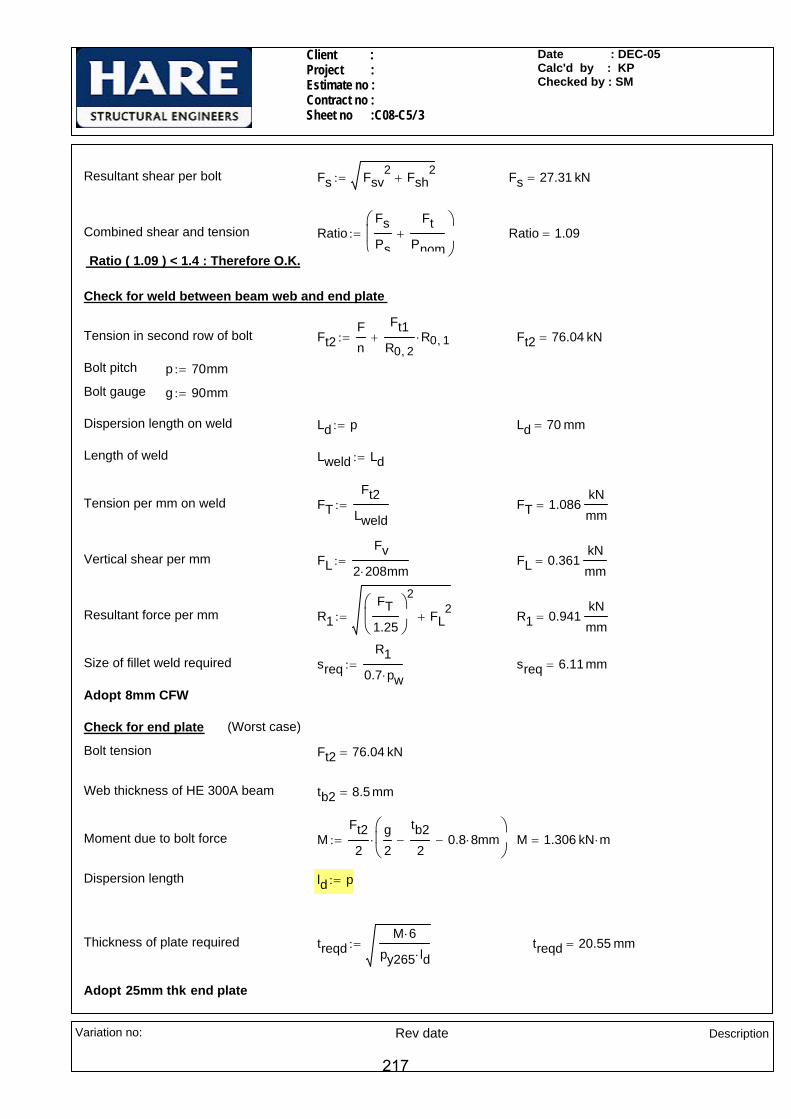
Client : Project : Estimate no : Contract no : Sheet no :C08-C5/ 3
Date : DEC-05Calc'd by : KPChecked by : SM
Resultant shear per bolt Fs Fsv2 Fsh
2+:= Fs 27.31 kN=
Combined shear and tension RatioFsPs
FtPnom
+⎛⎜⎜⎝
⎞
⎠:= Ratio 1.09=
Ratio ( 1.09 ) < 1.4 : Therefore O.K.
Check for weld between beam web and end plate
Tension in second row of bolt Ft2Fn
Ft1R0 2,
R0 1,⋅+:= Ft2 76.04 kN=
Bolt pitch p 70mm:=
Bolt gauge g 90mm:=
Dispersion length on weld Ld p:= Ld 70 mm=
Length of weld Lweld Ld:=
Tension per mm on weld FTFt2
Lweld:= FT 1.086
kNmm
=
Vertical shear per mm FLFv
2 208⋅ mm:= FL 0.361
kNmm
=
Resultant force per mm R1FT
1.25
⎛⎜⎝
⎞
⎠
2
FL2
+:= R1 0.941kNmm
=
Size of fillet weld required sreqR1
0.7 pw⋅:= sreq 6.11mm=
Adopt 8mm CFW
Check for end plate (Worst case)
Bolt tension Ft2 76.04 kN=
Web thickness of HE 300A beam tb2 8.5 mm=
Moment due to bolt force MFt22
g2
tb22
− 0.8 8⋅ mm−⎛⎜⎝
⎞
⎠⋅:= M 1.306 kN m⋅=
Dispersion length ld p:=
Thickness of plate required treqdM 6⋅
py265 ld⋅:= treqd 20.55 mm=
Adopt 25mm thk end plate
Variation no: Rev date Description
217

Client : Project : Estimate no : Contract no : Sheet no :C08-C5/ 4
Date : DEC-05Calc'd by : KPChecked by : SM
Check for tee flange plate (Worst case)
Thickness of Tee web plate ts 20mm:=
Moment due to bolt force MFt22
g2
ts2
− 0.8 8⋅ mm−⎛⎜⎝
⎞
⎠⋅:= M 1.087 kN m⋅=
Dispersion length ld p:=
Thickness of plate required treqdM 6⋅
py265 ld⋅:= treqd 18.75 mm=
Adopt 20mm thk tee flange plate
Check for tension capacity of incoming beam web
Tension capacity of beam web/ bolt tension PT py275 p⋅ tb2⋅:= PT 163.63 kN=
Tension in web Ftw 2 Ft2⋅:= Ftw 152.09 kN=
PT (163.62 kN) > Ftw (152.09 kN): Therefore O.K.
b1
Check for tee plate welds
Weld between tee flange/ end plate and HE300A top flange
Max. compression in top flangeof beam due to moment
Fc 2 Ft⋅0
2
n
R0 n,( )∑=
⎡⎢⎢⎣
⎤⎥⎥⎦
R0 2,⋅:= Fc 358.95 kN=
Width of end plate/tee flange plate wp 160mm:=
Effective width of beam flange b1 wp:= b1 160 mm=
Effective C/S area of beam Abeff Ab2 2 Wb2 b1−( ) Tb2⋅⎡⎣ ⎤⎦⋅−:= Abeff 7380 mm2=
Compressive force on beam top flange due to axial in beam
Fcab1 Tb1⋅
AbeffF⋅:= Fca 94.09 kN=
Total compression in top flange C Fc Fca+:= C 453.04 kN=
Horizontal shear per flange FfFh2
:= Ff 22 kN=
Length of weld available Lweld b1:= Lweld 160 mm=
Compression per mm FT1C
Lweld:= FT1 2.83
kNmm
=
Variation no: Rev date Description
218

Client : Project : Estimate no : Contract no : Sheet no :C08-C5/ 5
Date : DEC-05Calc'd by : KPChecked by : SM
Shear per mm FL1Ff
Lweld:= FL1 0.137
kNmm
=
Resultant force R2 FT12 FL1
0.6
⎛⎜⎝
⎞
⎠
2
+:= R2 2.841kNmm
=
Size of PPBW required s max 2 14⋅ 3+( )mmR2
py2753mm+
⎛⎜⎜⎝
⎞
⎠,
⎡⎢⎢⎣
⎤⎥⎥⎦
:= s 13.33 mm=
Adopt Full prep. PPBW.
48.75
54
Weld between tee flange/ end plate and HE300A bottom flange
Tension dispersed on beam bottom flange Ftf
Fn
Ft1+⎛⎜⎝
⎞⎠
48.7548.75 54+⋅:= Ftf 41.37 kN=
Tension per mm on beam bottom flange
FT2Ftf
48.75mm:= FT2 0.849
kNmm
=
Length of weld available Lweld1 2 Wb2⋅ tb2− 2 rb2⋅−:= Lweld1 537.5 mm=
Horizontal shear per mm on beam bottom flange
FL2Ff
Lweld1:= FL2 0.041
kNmm
=
Resultant shear per mm on beam bottom flange R3
FT21.25
⎛⎜⎝
⎞
⎠
2
FL22
+:= R3 0.680kNmm
=
Size of fillet weld required sreqR3
0.7 pw⋅:= sreq 4.42mm=
Adopt 6mm CFW
Weld between tee web and HE300A flange
7670
7046
2 x 65.28 kN
2 x 76.76 kN
2 x 88.24 kN
120.8
268.9 kN
191.64 kNTension in first row of bolt Ft0
Fn
Ft1R0 2,
R0 0,⋅+:= Ft0 64.89 kN=
Tension in second row of bolt Ft2Fn
Ft1R0 2,
R0 1,⋅+:= Ft2 76.04 kN=
Tension in third row of bolt FtFn
Ft1+:= Ft 87.2kN=
Max shear on the weld/side Fmax2 Ft0 76⋅ mm Ft2 146⋅ mm+ Ft 216⋅ mm+( )
46 70+ 70+ 76+( )mm:= Fmax 266.17 kN=
Variation no: Rev date Description
219
Client : Project : Estimate no : Contract no : Sheet no :C08-C5/ 6
Date : DEC-05Calc'd by : KPChecked by : SM
Length available for weld/side Lweld2 145.8mm 25mm−:= Lweld2 120.8 mm=
Shear per mm FL3Fmax
2Lweld2:= FL3 1.102
kNmm
=
Size of fillet weld required sreqFL3
0.7 pw⋅:= sreq 7.15mm=
Adopt 8mm CFW
Weld between HE300A supporting beam web and tee web
Size of fillet weld required sreqFL
0.7 pw⋅:= sreq 2.34mm=
Adopt 6mm CFW
Check for tee web plate
Width of web plate w 120.8mm:=
Thickness of plate required in shear treqFmax
0.6 0.9⋅ w⋅ py265⋅:= treq 15.4mm=
Adopt 20 thk plate as Tee web
Variation no: Rev date Description
220

Client : Project : Estimate no : Contract no : Sheet no : C08-C6/1
Date : DEC-05Calc'd by : KKNChecked by : DEC-05
CONNECTION NO - C08-C6
LOADS Vertical shear Tying force
PG525x250x174 <B256> Fv 705 kN⋅:= Fa 705 kN⋅:=
254 x 254 x 73 UC70
7070
7070
40
PG 525x250x174<B256>
1111
88
88
11mm Prep. PPBW (TYP)
160x15 THK END/ TOE PLATEWITH BOLTS @ 90X/CRS
10 THK STIFFENER(15x15 SNIPES)
Notes
All Bolts are M20 Grade 8.8All welds are 6mm CFW UNO All Main steel & fittings are S355
Variation no: Rev date Description
221
Client : Project : Estimate no : Contract no : Sheet no : C08-C6/2
Date : DEC-05Calc'd by : KKNChecked by : DEC-05
Ps 91.9kN:=
No of bolt rows nr 5:= Tension capacity of bolt Pnom 110kN:=
No of bolt columns nc 2:=
Total no of bolts n 10:=
Thickness of toe plate (Assumed) ttp 15mm:=
Eccentricity from centre line of supporting beam to tee flange plate & end plate interface
ewb1
2ttp+:= e 142.3 mm=
Moment due to the connection eccentricity
Mz Fv e⋅:= Mz 100.3 kN m⋅=
Taking rotation about centre of top beam flange Rr 57.5 127.5 197.5 267.5 337.5( )mm:=
Section modulus of bolt group( major axis)
Zn
2
0
4
n
Rr0 n,⎛⎝
⎞⎠
2∑=
⋅⎡⎢⎢⎣
⎤⎥⎥⎦
Rr0 4,
:= Zn 1446.11 mm=
Tensile force on Single bolt due to Mz
FtbMzZn
:= Ftb 69.37 kN=
Tension per bolt due to moment Ft Ftb:= Ft 69.4kN= < Pnom 110 kN=
SECTIONAL PROPERTIES
Supporting Beam 254x254x73 UC<B211>
Db1 254.1mm:= wb1 254.6mm:= Tb1 14.2mm:= rb1 12.7mm:= tb1 8.6mm:= db1 200.3mm:=
Incoming Beam PG 525x250x174<B256>
Db 525mm:= wb 250mm:= Tb 25mm:= tb 20mm:=
MATERIAL PROPERTIES
Design strength of S355 material - up to & including 16thk.
py355 355N
mm2⋅:= Design strength of fillet -
weld for S355 material pw 250N
mm2⋅:=
Design strength of S355 material - beyond 16thk. and including 40thk.
py345 345N
mm2⋅:= Bearing strength of S355 -
materialpbs355 550
N
mm2:=
Ultimate strength of S355 material pu355 392N
mm2⋅:=
Check for Bolt
Dia of bolt d 20mm:=
Diameter of hole Dh 22mm:= Shear capacity of bolt
Variation no: Rev date Description
222

Client : Project : Estimate no : Contract no : Sheet no : C08-C6/3
Date : DEC-05Calc'd by : KKNChecked by : DEC-05
Resultant shear per mm on weld
Size of weld required sR
pw 0.7⋅:= s 5.67mm=
Adopt 6mm CFW
Check for weld between web stiffener and the toe plate
135.
9022
5.7Length available for weld Lw Db1 2 Tb1⋅−( ) 135.9mm+:= Lw 361.6 mm=
Shear per mm on weld FLFv
2 Lw⋅:= FL 0.975
kNmm
=
Tension per mm on weld FTFt
75mm:= FT 0.925
kNmm
=
R FL2 FT
1.25
⎛⎜⎝
⎞
⎠
2
+:= R 1.224kNmm
=Resultant shear per mm on weld
Size of weld required sR
pw 0.7⋅:= s 6.99mm=
Adopt 8mm CFW.
Vertical shear per bolt FsFvn
:= Fs 70.5kN= < Ps 91.9kN=
Combined shear and tension RatioFsPs
FtPnom
+⎛⎜⎜⎝
⎞
⎠:= Ratio 1.398=
Ratio ( 1.398 ) < 1.4 : Therefore O.K.
Check for weld between beam web and end plate
Length available for weld Lw Db 2 Tb⋅− 2 8⋅ mm−( ):= Lw 459 mm=
Shear per mm on weld FLFv
2 Lw⋅:= FL 0.768
kNmm
=
Tensile force in the 4th bolt row Ftf
Ft Rr0 3,⋅
Rr0 4,
:= Ftf 55 kN=
Tension per mm on weld FTFtf
70mm:= FT 0.785
kNmm
=
R FL2 FT
1.25
⎛⎜⎝
⎞
⎠
2
+:= R 0.992kNmm
=
Variation no: Rev date Description
223

Client : Project : Estimate no : Contract no : Sheet no : C08-C6/4
Date : DEC-05Calc'd by : KKNChecked by : DEC-05
Ft3 2Fan
⋅64.9
64.9 72.5+( )⋅:= Ft3 66.6kN=
Max shear on the weld FmaxFt1 55.8⋅ mm( ) Ft2 125.8⋅ mm( )+ Ft3 195.8⋅ mm( )+
225.7mm( ):= Fmax 156 kN=
Length available for weld Lweld2wb1
2
tb12
− Ls−⎛⎜⎝
⎞
⎠:= Lweld2 108 mm=
Shear per mm FL3Fmax
2 Lweld2⋅:= FL3 0.722
kNmm
=
Size of fillet weld required sreqFL3
0.7 pw⋅:= sreq 4.13mm=
Adopt 6mm CFW
Check for tee web plate
Width of web plate w Lweld2:=
Thickness of plate required in shear treqFmax
0.6 0.9⋅ w⋅ py355⋅:= treq 7.5 mm=
Adopt 10 thk plate as Tee web
Check for weld between supporting beam web and the stiffener
Length of snipe provided Ls 15mm:=
Length available for weld Lw Db1 2 Tb1⋅− 2 Ls⋅−( ):= Lw 195.7 mm=
Shear per mm on weld FLFv
2 Lw⋅:= FL 1.801
kNmm
=
Size of weld required sFL
pw 0.7⋅:= s 10.3mm=
Adopt 11mm CFW
Check for weld between supporting beam flange and the web stiffener (Worst case - due to tie force)
7090
.864
.9
72.5
7560
.9
79.5kN
141kN
66.6kN
225.
7
7070
55.8
64.37kN
141kN
7025
.9
Tension in first row of bolt dispersed to the stiffener due to tie force
Ft1 2Fan
⋅93.8
93.8 72.5+( )⋅:= Ft1 79.5kN=
Tension in second row of bolt Ft2 2Fan
⋅:= Ft2 141 kN=
Tension in third row of bolt dispersed to the stiffener due to tie force
Variation no: Rev date Description
224
Client : Project : Estimate no : Contract no : Sheet no : C08-C6/5
Date : DEC-05Calc'd by : KKNChecked by : DEC-05
Tension per mm on weld FT16M
2Lw2
:= FT1 0.703kNmm
=
Resultant force per mm on weld R FL12 FT1
1.25
⎛⎜⎝
⎞
⎠
2
+:= R 0.983kNmm
=
Size of weld sR
0.7 pw⋅:= s 5.62mm=
Adopt 6mm CFW
Check for end plate / toe plate
Moment due to bolt force MFtf2
90mm2
tb2
− 0.8 6⋅ mm−⎛⎜⎝
⎞
⎠⋅:= M 0.83kN m⋅=
Dispersion length Ld 70mm:=
Thickness of plate required treqdM 6⋅
py355 Ld⋅:= treqd 14.2mm=
Adopt 15mm thk end plate and toe plate, O.K for tying also.
Check for weld between beam bottom flange and the glut stiffener
7090
.864
.9
72.5
7560
.9
79.5kN
141kN
66.6kN
225.
7
7070
55.8
64.37kN
141kN
7025
.9
Length available for weld Lw wb1:= Lw 254.60 mm=
Tension in fourth row of bolt dispersed to the glut stiffener due to tie force
Ft4 2Fan
⋅60.9
60.9 72.5+( )⋅:= Ft4 64.4kN=
Tension in fifth row of bolt dispersed to the glut stiffener due to tie force
Ft5 2Fan
⋅:= Ft5 141 kN=
Shear on the glut stiffener Ftg Ft4 Ft5+:= Ftg 205.4 kN=
Shear per mm on weld FL1FtgLw
:= FL1 0.807kNmm
=
Moment induced on weld M Ft4 25.9⋅ mm Ft5 95.9⋅ mm+:= M 15.2kN m⋅=
Variation no: Rev date Description
225

Client : Project : Estimate no : Contract no : Sheet no : C08-C6/6
Date : DEC-05Calc'd by : KKNChecked by : DEC-05
Check for weld between beam top flange and the end plate
Compression for on top flange C 2
0
4
n
Ft Rr0 n,⋅
Rr0 4,∑=
⎛⎜⎜⎝
⎞
⎠
:= C 406 kN=
Length available for weld Lw 160mm:=
Compression on weld per mm FTCLw
:= FT 2.537kNmm
=
Size of weld s maxFT
py3453mm+ 2 15 3+( )mm,
⎡⎢⎢⎣
⎤⎥⎥⎦
:= s 10.7mm=
Adopt 11mm PPBW
Variation no: Rev date Description
226

Client : Project : Estimate no : Contract no : Sheet no : C09-C1/1
Date : DEC-05Calc'd by : KKNChecked by : SM
All bolts are M20 Grade 8.8All main steel and fittings are grade S355All welds are 6mm CFW UNO
Notes
12 PPBW
ASB 280x105 <B003>
ASB
300X
196
<B00
9>
ASB
280x
74 <
B001
>
ASB 280x124<B004>
ASB 280x124<B004> ASB 280x105 <B003>
65(T
YP)
SECTION A-A
SECTION B-B
ASB 300X196 <B009>ASB 280x74 <B001>
55
90
TOS +11.947
TOS +11.915
TOS +11.903
TOS +11.911
8080
300x200x16 RHS <C074>
300x200x16 RHS <C074>
300x200x16 RHS <C074>
8080
260x90x35 PFC
260x90x35 PFC
15 THK WEB PLATE (TYP)
300x90x41 PFC
160x15 THK END PLATE (TYP)
AA
90
BB
8080
(TYP)
160x15 THK END PLATE (TYP)
200x90x30 PFC
10
8
(TYP) 8
Fa3 391kN:=Fv3 391kN:=ASB 280x105Fa1 371kN:=Fv1 371kN:=ASB 280x124
Fa2 400kN:=Fv2 400kN:=ASB 300x196Fa 227kN:=Fv 227kN:=ASB 280x74
Tie forceVertical shearTie forceVertical shearLOADS
CONNECTION NO - C09-C1
Variation no: Rev date
Description
227

Client : Project : Estimate no : Contract no : Sheet no : C09-C1/2
Date : DEC-05Calc'd by : KKNChecked by : SM
pu355 392N
mm2⋅:=Ultimate tensile strength of S355
material
MATERIAL PROPERTIES
dc2 208mm:=rc2 12mm:=tc2 8mm:=Tc2 14mm:=wc2 90mm:=Dc2 260mm:=
PFC 260x90x35
dc1 245mm:=rc1 12mm:=tc1 9mm:=Tc1 15.5mm:=wc1 90mm:=Dc1 300mm:=
PFC 300x90x41
dc 148mm:=rc 12mm:=
n 6:=Total no of bolts
nc 2:=No of bolt columns
nr 3:=No of bolt rows
p 80mm:=Pitch
g 90mm:=Gauge
Dh 22mm:=Diameter of hole
d 20mm:=Dia of bolt
Check for Bolt (Worst case)
pw 250N
mm2⋅:=
Design strength of fillet - weld for S355 material
pbs355 550N
mm2:=Bearing strength of S355 -
material
Tbt2 40mm:=wbt2 183mm:=Db2 342mm:=
ASB 300x196<B009>
db1 196mm:=tb1 13mm:=wbb1 288mm:=Tb1 26mm:=wbt1 178mm:=Db1 296mm:=
ASB 280x124<B004>
db 196mm:=tb 10mm:=wbb 285mm:=Tb 14mm:=wbt 175mm:=Db 272mm:=
ASB 280x74<B001>
SECTIONAL PROPERTIES
tc 7mm:=Tc 14mm:=wc 90mm:=Dc 200mm:=
PFC 200x90x30
T 16mm:=w 200mm:=D 300mm:=
Supporting RHS 300x200x16 <C074>
db3 196mm:=tb3 11mm:=wbb3 286mm:=Tbt3 22mm:=wbt3 176mm:=Db3 288mm:=
ASB 280x105<B003>
db2 208mm:=tb2 20mm:=wbb2 293mm:=
Variation no: Rev date
Description
228

Client : Project : Estimate no : Contract no : Sheet no : C09-C1/3
Date : DEC-05Calc'd by : KKNChecked by : SM
Size of weld required sreq.FL
pw 0.7⋅:= sreq. 5.7 mm=
Considering Tying force
FTFa3n p⋅
:= FT 0.815kNmm
=Tensile force per mm on weld
Size of weld required sreqFT
pw 0.7⋅ 1.25⋅:= sreq 3.72mm=
Adopt 6 mm C.F.W
Check for weld between PFC and RHS
ASB 300x196<B009> (Worst case)
Considering Vertical shear force (Worst case is right hand side weld)
Length available for weld Lw Db3:=
Shear per mm on weld FL
138Fv2
246
Lw:= FL 0.779
kNmm
=
Shear capacity of bolt Ps 91.9kN:=
Tension capacity of bolt Pnom 110kN:=
Considering Vertical shear force
Shear per boltFs
Fv2n
:= Fs 66.67 kN=
Ps (91.9 kN) > Fs (66.67 kN): Therefore O.K.
Considering Tying force
Tension per bolt FtFa2
n:= Ft 66.67 kN=
Pnom (110 kN) > Ft (66.67 kN): Therefore O.K.
Check for weld between beam web and end plate (Worst case)
Considering Vertical shear force
Length available for weld Lw db3:=
Shear per mm on weld FLFv32 Lw⋅
:= FL 0.997kNmm
=
Variation no: Rev date
Description
229
Client : Project : Estimate no : Contract no : Sheet no : C09-C1/4
Date : DEC-05Calc'd by : KKNChecked by : SM
Size of weld required sreqFT
pw 0.7⋅ 1.25⋅:= sreq 3.56mm=
Adopt 10 mm C.F.W
ASB 280x124<B004>/ASB 280x74<B001>/ASB 300x196<B010>(Worst case)
Considering Vertical shear force (Worst case ASB 280x124)
Length available for weld Lw1 Db1:= Lw1 296 mm=
Shear per mm on weld FL1
Fv1
2
Lw:= FL1 0.644
kNmm
=
Eccentricity of weld from working point e1 105mm:=
Moment due to eccentricity M1Fv12
e1⋅:= M1 19477.5 kN mm⋅=
Section modulus of the weld Z1Lw1
2
6:= Z1 14602.67 mm2
=
Eccentricity of weld from working point e1 105mm:=
Moment due to eccentricity M138Fv2
246e1⋅:= M 23560.98 kN mm⋅=
Section modulus of the weld ZLw
2
6:= Z 13824 mm2
=
Tension per mm on weld FTMZ
:= FT 1.704kNmm
=
Resultant force per mm on weld RFT
1.25
⎛⎜⎝
⎞
⎠
2
FL2
+:= R 1.57kNmm
=
Size of weld required sreq.R
pw 0.7⋅:= sreq. 8.97mm=
Considering Tying force
FT
138Fa2
246
Lw:= FT 0.779
kNmm
=Tensile force per mm on weld
Variation no: Rev date
Description
230
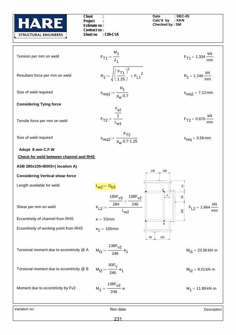
Client : Project : Estimate no : Contract no : Sheet no : C09-C1/5
Date : DEC-05Calc'd by : KKNChecked by : SM
Considering Vertical shear force
Length available for weld Lw2 Db3:=
Shear per mm on weld FL2
185Fv3284
138Fv2246
+
Lw2:= FL2 1.664
kNmm
=
Eccentricity of channel from RHS e 53mm:=
Eccentricity of working point from RHS e1 105mm:=
Torsional moment due to eccentricity @ A Mt1138Fv2
246e1⋅:= Mt1 23.56 kN m⋅=
Torsional moment due to eccentricity @ B Mt293Fv246
e1⋅:= Mt2 9.01kN m⋅=
Moment due to eccentricity by Fv2 M1138Fv2
246e⋅:= M1 11.89 kN m⋅=
Tension per mm on weld FT1M1Z1
:= FT1 1.334kNmm
=
Resultant force per mm on weld R1FT11.25
⎛⎜⎝
⎞
⎠
2
FL12
+:= R1 1.246kNmm
=
Size of weld required sreq1R1
pw 0.7⋅:= sreq1 7.12mm=
Considering Tying force
FT2
Fa2
2
Lw1:= FT2 0.676
kNmm
=Tensile force per mm on weld
Size of weld required sreq2FT2
pw 0.7⋅ 1.25⋅:= sreq 3.56mm=
Adopt 8 mm C.F.W
Check for weld between channel and RHS
ASB 280x105<B003>( location A)
A
B
138 108
15393
9918
5
e
e1
Variation no: Rev date
Description
231
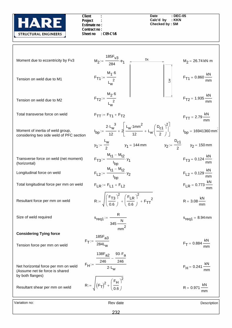
Client : Project : Estimate no : Contract no : Sheet no : C09-C1/6
Date : DEC-05Calc'd by : KKNChecked by : SM
Longitudinal force on weld FL2Mt1 Mt2−
Ibpy2⋅:= FL2 0.129
kNmm
=
Total longitudinal force per mm on weld FLR FL1 FL2+:= FLR 0.773kNmm
=
Resultant force per mm on weld RFT30.6
⎛⎜⎝
⎞
⎠
2 FLR0.6
⎛⎜⎝
⎞
⎠
2
+ FTT2
+:= R 3.08kNmm
=
Size of weld required sreq1R
345N
mm2
:= sreq1 8.94mm=
Considering Tying force
FT185Fa3284Lw
:= FT 0.884kNmm
=Tension force per mm on weld
FH
138Fa2246
93 Fa⋅
246−
2 Lw⋅:=Net horizontal force per mm on weld FH 0.241
kNmm
=(Assume net tie force is shared by both flanges)
R FT( )2FH0.6
⎛⎜⎝
⎞
⎠
2
+:=Resultant shear per mm on weld R 0.971kNmm
=
Lw
DcMoment due to eccentricity by Fv3 M2185Fv3
284e1⋅:= M2 26.74 kN m⋅=
FT1M1 6⋅
Lw2
:= FT1 0.860kNmm
=Tension on weld due to M1
FT2M2 6⋅
Lw2
:= FT2 1.935kNmm
=Tension on weld due to M2
Total transverse force on weld FTT FT1 FT2+:= FTT 2.79kNmm
=
Moment of inertia of weld group,considering two side weld of PFC section
Ibp2 Lw
3⋅
122
Lw 1⋅ mm2
12Lw
Dc12
⎛⎜⎝
⎞
⎠
2
⋅+
⎡⎢⎢⎣
⎤⎥⎥⎦
+:= Ibp 16941360 mm3=
y1Lw2
:= y1 144 mm= y2Dc1
2:= y2 150 mm=
Transverse force on weld (net moment)(horizontal)
FT3Mt1 Mt2−
Ibpy1⋅:= FT3 0.124
kNmm
=
Variation no: Rev date
Description
232

Client : Project : Estimate no : Contract no : Sheet no : C09-C1/7
Date : DEC-05Calc'd by : KKNChecked by : SM
Tension on weld due to M1
FT2M2 6⋅
Lw2
:= FT2 1.035kNmm
=Tension on weld due to M1
Total transverse force on weld FTT FT1 FT2+:= FTT 1.364kNmm
=
Moment of inertia of weld group,considering two side weld of PFC section
Ibp2 Lw
3⋅
122
Lw 1⋅ mm2
12Lw
Dc12
⎛⎜⎝
⎞
⎠
2
⋅+
⎡⎢⎢⎣
⎤⎥⎥⎦
+:= Ibp 16941360 mm3=
y1Lw2
:= y1 144 mm= y2Dc1
2:= y2 150 mm=
Transverse force on weld (net moment)(horizontal)
FT3Mt1 Mt2−
Ibpy1⋅:= FT3 0.124
kNmm
=
Longitudinal force on weld FL2Mt1 Mt2−
Ibpy2⋅:= FL2 0.129
kNmm
=
Size of weld required sreq1 maxR
345N
mm2
3mm+⎛⎜⎜⎜⎝
⎞⎟
⎠
2 15.5⋅ 3+( )mm,⎡⎢⎢⎢⎣
⎤⎥⎥⎥⎦
:= sreq1 10.87 mm=
Adopt 12 mm PPBW
ASB 280x105<B003>( location B)
Considering Vertical shear force
Length available for weld Lw Db3:=
A
B
138 108
15393
9918
5
e
e1Shear per mm on weld FL1
93Fv246
99Fv3284
+
Lw:= FL1 0.771
kNmm
=
Moment due to eccentricity by Fv M193Fv246
e⋅:= M1 4.55kN m⋅=
Moment due to eccentricity by Fv3 M299Fv3284
e1⋅:= M2 14.31 kN m⋅=
FT1M1 6⋅
Lw2
:= FT1 0.329kNmm
=
Variation no: Rev date
Description
233
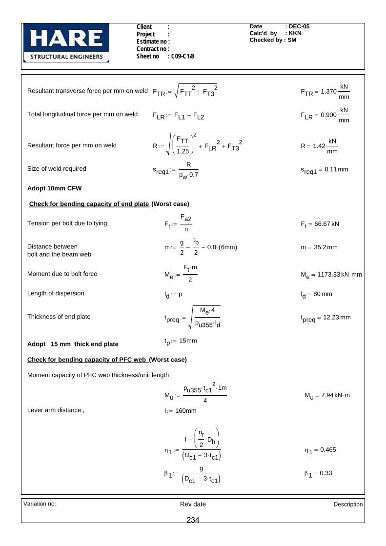
Client : Project : Estimate no : Contract no : Sheet no : C09-C1/8
Date : DEC-05Calc'd by : KKNChecked by : SM
MeFt m⋅
2:= Me 1173.33 kN mm⋅=
Length of dispersion ld p:= ld 80 mm=
Thickness of end plate tpreqMe 4⋅
pu355 ld⋅:= tpreq 12.23 mm=
tp 15mm:=Adopt 15 mm thick end plate
Check for bending capacity of PFC web (Worst case)
Moment capacity of PFC web thickness/unit length
Mupu355 tc1
2⋅ 1⋅ m
4:= Mu 7.94kN m⋅=
Lever arm distance , l 160mm:=
η1
lnr2
Dh⋅⎛⎜⎝
⎞
⎠−
Dc1 3 tc1⋅−( ):= η1 0.465=
β1g
Dc1 3 tc1⋅−( ):= β1 0.33=
Resultant transverse force per mm on weld FTR FTT2 FT3
2+:= FTR 1.370
kNmm
=
Total longitudinal force per mm on weld FLR FL1 FL2+:= FLR 0.900kNmm
=
Resultant force per mm on weld RFTT1.25
⎛⎜⎝
⎞
⎠
2
FLR2
+ FT32
+:= R 1.42kNmm
=
Size of weld required sreq1R
pw 0.7⋅:= sreq1 8.11mm=
Adopt 10mm CFW
Check for bending capacity of end plate (Worst case)
Tension per bolt due to tying FtFa2
n:= Ft 66.67 kN=
Distance between bolt and the beam web
mg2
tb2
− 0.8 6mm( )⋅−:= m 35.2mm=
Moment due to bolt force
Variation no: Rev date
Description
234
Client : Project : Estimate no : Contract no : Sheet no : C09-C1/9
Date : DEC-05Calc'd by : KKNChecked by : SM
Pt (587.06 kN) > Ftie (400 kN): Therefore O.K.
Ftie 400 kN=Ftie Fa2:=Tie force (worst condition)
Pt 587.06 kN=
Pt8.Mu
1 β1−( ) 1⋅ mη1( ) 1.5 1 β1−( )0.5
⋅ 1 γ1−( )0.5⋅+⎡
⎣⎤⎦⋅:=Tie capacity of PFC web after
providing reinforcing plate
γ1 0.088=γ1Dh
Dc1 3 tt⋅−( ):=
β1 0.361=β1g
Dc1 3 tt⋅−( ):=
η1 0.51=η1
lnr2
Dh⋅⎛⎜⎝
⎞
⎠−
Dc1 3 tt⋅−( ):=
l 160mm:=Lever arm distance ,
Mu 28.32 kN m⋅=
γ1Dh
Dc1 3 tc1⋅−( ):= γ1 0.081=
Tie capacity of PFC web Pt8.Mu
1 β1−( ) 1⋅ mη1( ) 1.5 1 β1−( )0.5
⋅ 1 γ1−( )0.5⋅+⎡
⎣⎤⎦⋅:=
Pt 155.63 kN=
Tie force (worst condition) Ftie Fa2:= Ftie 400 kN=
Ftie (400 kN) > Pt (155.63 kN): Therefore PROVIDE REINFORCING PLATE
Check for bending capacity of PFC web after providing reinforcing plate
Assumed thickness of reinforcing plate tw 15mm:=
Total thickness of the PFC web, considering after providing web plate tt tc2
2 tw2
+:= tt 17 mm=
Moment capacity of PFC web thickness/unit length
Mupu355 tt
2⋅ 1⋅ m
4:=
Variation no: Rev date
Description
235
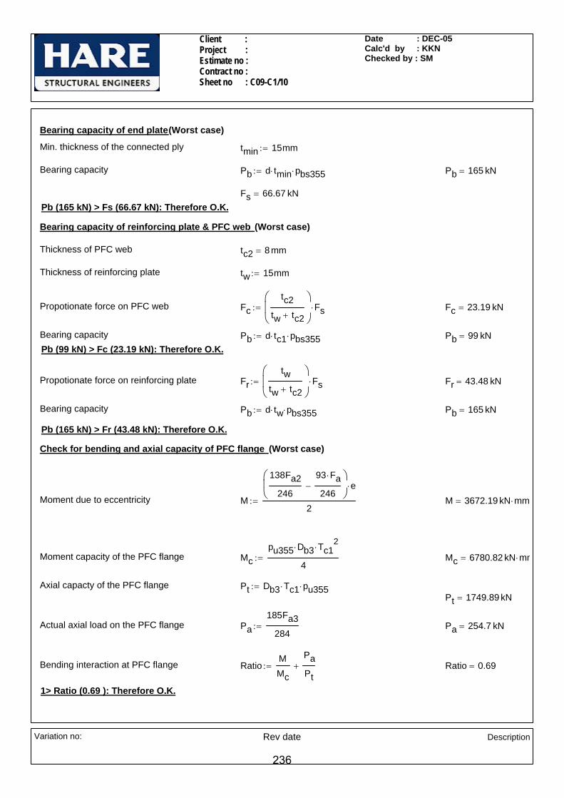
Client : Project : Estimate no : Contract no : Sheet no : C09-C1/10
Date : DEC-05Calc'd by : KKNChecked by : SM
Fr 43.48 kN=
Bearing capacity Pb d tw⋅ pbs355⋅:= Pb 165 kN=
Pb (165 kN) > Fr (43.48 kN): Therefore O.K.
Check for bending and axial capacity of PFC flange (Worst case)
Moment due to eccentricity M
138Fa2246
93 Fa⋅
246−
⎛⎜⎝
⎞
⎠e⋅
2:= M 3672.19 kN mm⋅=
Moment capacity of the PFC flange Mcpu355 Db3⋅ Tc1
2⋅
4:= Mc 6780.82 kN mm⋅=
Axial capacty of the PFC flange Pt Db3 Tc1⋅ pu355⋅:=Pt 1749.89 kN=
Actual axial load on the PFC flange Pa185Fa3
284:= Pa 254.7 kN=
Bending interaction at PFC flange RatioMMc
PaPt
+:= Ratio 0.69=
1> Ratio (0.69 ): Therefore O.K.
Bearing capacity of end plate(Worst case)
Min. thickness of the connected ply tmin 15mm:=
Bearing capacity Pb d tmin⋅ pbs355⋅:= Pb 165 kN=
Fs 66.67 kN=Pb (165 kN) > Fs (66.67 kN): Therefore O.K.
Bearing capacity of reinforcing plate & PFC web (Worst case)
Thickness of PFC web tc2 8 mm=
Thickness of reinforcing plate tw 15mm:=
Propotionate force on PFC web Fctc2
tw tc2+
⎛⎜⎜⎝
⎞
⎠Fs⋅:= Fc 23.19 kN=
Bearing capacity Pb d tc1⋅ pbs355⋅:= Pb 99 kN=Pb (99 kN) > Fc (23.19 kN): Therefore O.K.
Propotionate force on reinforcing plate Frtw
tw tc2+
⎛⎜⎜⎝
⎞
⎠Fs⋅:=
Variation no: Rev date
Description
236