filtered circular catalog mil-dtl-38999 fi lter connectors are designed to meet or exceed all...
TRANSCRIPT
FILTER CIRCULaRconnectoRs
2
table of contents
MIL-DTL-38999 .................................................................3 Series I ..........................................................................................................................4 Series II .........................................................................................................................5 Series III and IV.............................................................................................................6 Layouts..........................................................................................................................7 How to order..................................................................................................................8
MIL-DTL-83723 .................................................................9 Type B .........................................................................................................................10 Layouts........................................................................................................................11 How to order................................................................................................................12
MIL-C-26482 ...................................................................13 Receptacles ................................................................................................................14 Layouts........................................................................................................................15 How to order................................................................................................................16
Electrical Characteristics .............................................................................................17 Performance Data .......................................................................................................20 Contact Termination ....................................................................................................21 Solderless Filter Connectors .......................................................................................22 Filter Adapters .............................................................................................................23

3
MIL-DTL-38999 fi lter connectors are designed to meet or exceed all applicable requirements of Series I, II, III and IV. Filter connectors are intermateable and interchangeable with the standard non-fi ltered connectors.
Smiths Connectors designs and manufactures a full spectrum of sophisticated fi lter connector products. Our specialty is in the design of interconnect solutions addressing EMI/RFI fi ltering, and transient protection to meet demanding HIRF and Lightning requirements.
In addition to MIL-Spec interface type products, many of our designs are unique, built to conform to customer specifi cations requiring a high level of integration, special packaging, and critical electrical performance. Innovation is our distinction and our products address a wide variety of applications. Our achievements lead the industry in the design and manufacture of special fi lter connector products.
ouR DesIgn stRategySmiths Connectors design strategy for fi lter connectors is based on extensive experience with fi lter capacitor arrays and diodes. Our engineers understand the extreme environmental conditions that can cause a fi lter or diode to fail or, worse yet, cause a system dysfunction. This design strategy is built on the foundation of system reliability and the effi cient use of available space. The capacitor array is protected from thermally induced mechanical stresses by a barrier located between the capacitor array surface and the epoxy fi lled region. This barrier isolates the epoxy and the ceramic array and prevents damage to the array from the expansion infl uence of the epoxy.
MoDulaRIzatIonA disciplined design approach that employs methods of grouping multiple components into subassemblies wherever feasible. Such subassemblies may include a fi lter module, diode module, circuit assembly module and a transition interface assembly. Modularization results in cleaner, more standardized designs that provide fl exibility in maintaining and upgrading the connector. An important advantage of modularization is that individual modules may be removed or replaced in the fi eld without disturbing other subassemblies and components.
IntegRatIonThere is considerable unused space available in a standard non-fi ltered connector. Smiths Connectors takes advantage of this space by removing components from elsewhere in the system and integrating them within the connector freeing up valuable board space. Isolating components electrically eliminates external wire connections and decreases crosstalk. The connector shell protects critical components from environmental or mechanical damage.
Smith Connectors provides specialty, enhanced performance connectors and cable assemblies and as such does not currently offer circular, rack and panel, or D-subminiature connectors that are listed on military standard Qualifi ed Products Lists (QPL) per applicable detail specifi cation sheets. Smith Connectors’ connectors are fully intermateable with applicable QPL products and meet the applicable requirements of all military standards listed in this catalog.
MIl-Dtl-38999 connectoRs
MATERIALS AND FINISHES
Shell Aluminum alloy/Steel/Composite
Insulator High grade plastic/epoxy
Contacts Copper alloy, gold plate
Grommet & Seal Silicon base elastomer
Jam Nut Aluminum alloy
Ground Plane Brass, silver plate
Capacitor Barium Titanate
Inductor Ferrite bead

4
Ms27468 JaM nut Receptacle
Ms27505 squaRe flange Receptacle ReaR Mount
Ms27466 squaRe flange Receptacle fRont Mount
X
KSee ContactTermination
M
F dia
R
S
1.400 MAXPi Filter
1.200 MAXC Filter
P Dia4 Holes
M
K
F dia
R
S
1.400 MAXPi Filter
1.200 MAXC Filter
P Dia4 Holes
X
See ContactTermination
±.005
M
.125 MAX
K
F diaO Flat
RHex
1.400 MAXPi Filter
1.200 MAXC Filter
.608
S
DD dia
See ContactTermination
X
.915
MIl-Dtl-38999 seRIes I
shell size
f + .001 -.005
K + .015 -.000
M + .000 -.005
p Dia + .010 -.005
R bsc
s + .020
X Max. Dia
9 0.572
0.0850.820
0.128
0.3595 0.938 .500
11 .700 0.406 1.031 .620
13 .850 0.453 1.125 .740
15 .975 0.4845 1.219 .890
17 1.100 0.531 1.312 1.000
19 1.207
0.115
0.578 1.438 1.120
21 1.332
0.790
0.625 1.562 1.250
23 1.4570.147
0.6875 1.688 1.390
25 1.582 .750 1.812 1.500
shell size
f + .001 -.005
K + .015 -.000
M + .000 -.005
p Dia + .010 -.005
R bsc
s + .020
X Max. Dia
9 0.572
0.0850.632
0.128
0.3595 0.938 .500
11 .700 0.406 1.031 .620
13 .850 0.453 1.125 .740
15 .975 0.4845 1.219 .890
17 1.100 0.531 1.312 1.000
19 1.207
0.115
0.578 1.438 1.120
21 1.332
0.602
0.625 1.562 1.250
23 1.4570.147
0.6875 1.688 1.390
25 1.582 .750 1.812 1.500
shell size
f + .001 -.005
K + .015 -.000
M thread
o flat + .000 -.010
R Hex + .017 -.016
s + .016
X Max. Dia
DD + .016
9 0.572
0.085
.6875-24 .655 .875 1.062 .500 1.188
11 .700 .8125-20 .755 1.000 1.250 .620 1.375
13 .850 1.000-20 .942 1.188 1.375 .740 1.5
15 .975 1.125-18 1.066 1.312 1.500 .890 1.625
17 1.100 1.250-18 1.191 1.438 1.625 1.000 1.75
19 1.207
0.115
1.375-18 1.316 1.562 1.812 1.120 1.938
21 1.332 1.500-18 1.441 1.688 1.938 1.250 2.062
23 1.457 1.625-18 1.566 1.812 2.062 1.390 2.188
25 1.582 1.750-18 1.691 2.000 2.188 1.500 2.312
5
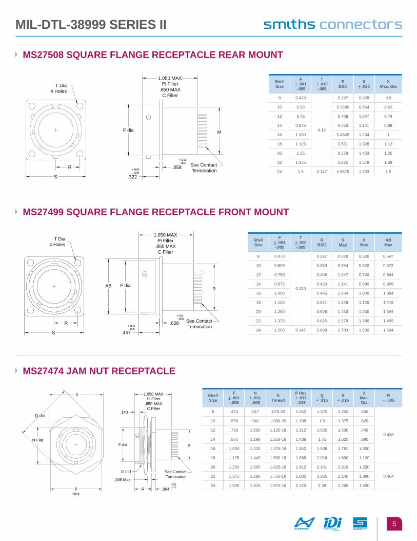
Ms27474 JaM nut Receptacle
Ms27499 squaRe flange Receptacle fRont Mount
Ms27508 squaRe flange Receptacle ReaR Mount
See ContactTermination
M
+.011-.000
.058+.000-.005
.322
F dia
R
S
1.050 MAXPi Filter
.850 MAXC Filter
T Dia4 Holes
See ContactTermination
X
-.000+.011
.058-.005+.000
.447
R
S
1.050 MAXPi Filter
.850 MAXC Filter
F diaAB
T Dia4 Holes
See ContactTermination
XF dia
-.010+.011
.094R
.109 Max
G thd
PHex
1.050 MAXPi Filter
.850 MAXC Filter
.140Q dia
N Flat
S
MIl-Dtl-38999 seRIes II
shell size
f + .001 -.005
n + .001 -.006
g thread
p Hex + .017 -.016
q + .016
s + .016
X Max. Dia
R + .005
8 .473 .817 .875-20 1.062 1.375 1.250 .500
0.438
10 .590 .941 1.000-20 1.188 1.5 1.375 .620
12 .750 1.065 1.125-18 1.312 1.625 1.500 .740
14 .875 1.190 1.250-18 1.438 1.75 1.625 .890
16 1.000 1.320 1.375-18 1.562 1.938 1.781 1.000
18 1.125 1.440 1.500-18 1.688 2.016 1.890 1.120
20 1.250 1.565 1.625-18 1.812 2.141 2.016 1.250
0.46422 1.375 1.690 1.750-18 2.000 2.265 2.140 1.390
24 1.500 1.815 1.875-16 2.125 2.39 2.265 1.500
shell size
f + .001 -.005
t + .010 -.005
R bsc
s Max
X Max
ab Max
8 0.473
0.120
0.297 0.828 0.500 0.547
10 0.590 0.360 0.954 0.620 0.672
12 0.750 0.406 1.047 0.740 0.844
14 0.875 0.453 1.141 0.890 0.969
16 1.000 0.485 1.234 1.000 1.094
18 1.125 0.531 1.328 1.120 1.219
20 1.250 0.578 1.453 1.250 1.344
22 1.375 0.625 1.578 1.390 1.469
24 1.500 0.147 0.688 1.703 1.500 1.594
shell size
f + .001 -.005
t + .010 -.005
R bsc
s + .020
X Max. Dia
8 0.473
0.12
0.297 0.828 0.5
10 0.59 0.3595 0.954 0.62
12 0.75 0.406 1.047 0.74
14 0.875 0.453 1.141 0.89
16 1.000 0.4845 1.234 1
18 1.125 0.531 1.328 1.12
20 1.25 0.578 1.453 1.25
22 1.375 0.625 1.578 1.39
24 1.5 0.147 0.6875 1.703 1.5
6
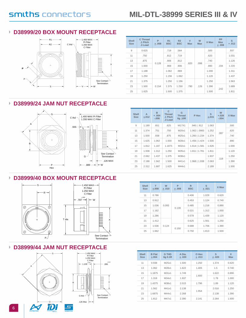
D38999/20 boX Mount Receptacle
D38999/24 JaM nut Receptacle
S
P
PP
1.400 MAXPi Filter
1.200 MAXC Filter
C thd
R1
R2
See ContactTermination
WV
X
1.400 MAX Pi Filter1.200 MAX C Filter
C thd
X
.126 MAX
W
See ContactTermination
.889
G
.555
PHex
B
S
A
D38999/40 boX Mount Receptacle
D38999/44 JaM nut Receptacle
1.450 MAXPi Filter
1.250 MAXC Filter
See ContactTermination
X
±.030
W.787
T dia
P
R
S
See ContactTermination
.126 Max
G thd
OHex
±.012
.095
X
±.0181.100
B
1.450 MAXPi Filter
1.250 MAXC Filter
A
S
shell size
c thread .1 pitch .3 lead
p + .008
R1 bsc
R2 bsc
V Max
W Max X Max
pp Max
+ .008
s + .012
9 0.625
0.128
.719 .564
.820 .098
.500
.194
.937
11 .750 .812 .719 .620 1.031
13 .875 .906 .812 .740 1.126
15 1.000 .969 .906 .890 1.220
17 1.188 1.062 .969 1.000 1.311
19 1.250 1.156 1.062 1.120 1.437
21 1.375
0.154
1.250 1.156
.790 .126
1.250 1.563
23 1.500 1.375 1.250 1.390.242
1.689
25 1.625 1.500 1.375 1.500 1.811
shell size
a +.012
b + .004 -.006
c thread .1 pitch .3 lead
g thread 6g .10R
p Hex s +.015
W +.028 -.004
X Max
9 1.189 .651 .625 M17X1 .945 | .912 1.063
.087
.500
11 1.374 .751 .750 M20x1 1.062 | .0983 1.252 .620
13 1.500 .938 .875 M25x1 1.260 | 1.234 1.374 .740
15 1.625 1.062 1.000 M28x1 1.456 | 1.424 1.500 .890
17 1.812 1.187 1.1875 M32x1 1.614 | 1.581 1.626 1.000
19 1.938 1.312 1.250 M35x1 1.811 | 1.781 1.811
.118
1.120
21 2.062 1.437 1.375 M38x1
1.968 | 1.938
1.937 1.250
23 2.188 1.562 1.500 M41x1 2.063 1.390
25 2.312 1.687 1.625 M44x1 2.189 1.500
shell size
t +.008
W + .010
p + .008
R bsc
s + .021 X Max
11 0.786
0.0930.139
0.406 1.029 0.620
13 0.912 0.453 1.124 0.740
15 1.036 0.485 1.218 0.890
17 1.162 0.531 1.312 1.000
19 1.286 0.578 1.439 1.120
21 1.412
0.124
0.625 1.561 1.250
23 1.5360.150
0.688 1.706 1.390
25 1.662 0.750 1.813 1.500
shell size
b flat +.004
g tHD 6g 0.1R
a Dia. + .020
o Hex + .013
s + .020
X Max
11 0.938 M25x1 1.500 1.250 1.374 0.620
13 1.062 M28x1 1.622 1.405 1.5 0.740
15 1.1875 M31x1 1.7491.600
1.622 0.890
17 1.318 M34x1 1.937 1.78 1.000
19 1.4375 M38x1 2.015 1.796 1.89 1.120
21 1.562 M41x1 2.1381.954
2.016 1.250
23 1.6875 M44x1 2.268 2.138 1.390
25 1.812 M47x1 2.390 2.141 2.264 1.500
MIl-Dtl-38999 seRIes III & IV
7
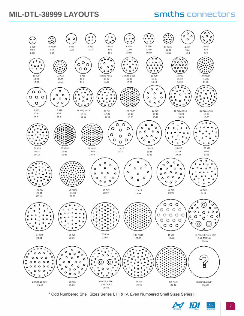
* Odd Numbered Shell Sizes Series I, III & IV, Even Numbered Shell Sizes Series II
14-5
5 #16
6 #22D9-35
3 #20
8-98
17-26 26 #20
19 #20 15-1913-35
22 #22
8 #20
12-8
4 #1613-4
13 #22D11-3511-99
7 #20 6 #2011-98 11-2
2 #16
14 #20, 1 #16
5 #20
10-5
10 #20
12-9813-98
13-89-988-35
11-510-98 12-410-3510-99
12-35
15-58 #20, 4#16
15-9714-97
15-15 18 #20
14-18 15-18
14-19
37 #22D15-3514-35
6 #1217-616-6
8 #1617-816-8
21 #20, 2 #1617-9916-99
11 #1221-11
25 #2021-2520-25
41 #2021-4120-41
79 #22D21-3520-35
16 #1621-1620-16
24 #2021-2420-24
32 #2019-3218-32
66 #22D19-3518-35
67 #22D19-4518-45
26 #20, 2 #1619-2818-2816-26
55 #22D17-3516-35
29 #20, 1 #1619-3018-30
11-44 #20
14-15
11 #16 19-11 18-11
16 #1623-97
11 #1623-99
19 #1225-19
10 #20, 13 #16, 4 #123 #8 TWINAX
25-20
21 #1623-21
32 #2023-32
23 #20, 20 #1625-43
29 #1625-29
34 #2023-34
36 #2023-36
40 #20, 4 #162 #8 COAX
25-46
61 #2025-61
55 #2023-55
100 #22D23-35
128 #22D25-35
Custom Layout*XX-XX
MIl-Dtl-38999 layouts
8
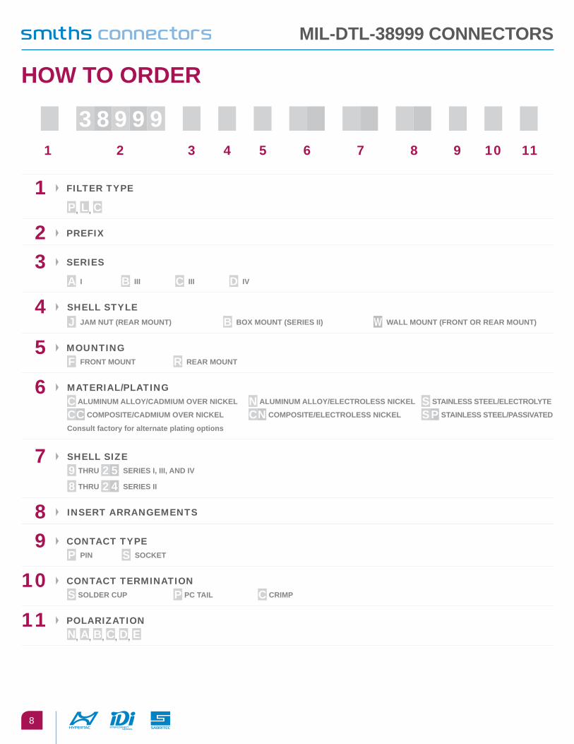
MIl-Dtl-38999 connectoRs
1 2 3 4 5 6 7 8 9 10 11
1 FILTER TYPE
p, l, c
2 PREFIx
3 SERIES
a I b III c III D IV
4 ShELL STYLE
J JaM nut (ReaR Mount) b boX Mount (seRIes II) W Wall Mount (fRont oR ReaR Mount)
5 MOUNTING
f fRont Mount R ReaR Mount
6 MaTERIaL/PLaTING
c aluMInuM alloy/caDMIuM oVeR nIcKel n aluMInuM alloy/electRoless nIcKel s staInless steel/electRolyte
cc coMposIte/caDMIuM oVeR nIcKel cn coMposIte/electRoless nIcKel sp staInless steel/passIVateD
consult factory for alternate plating options
7 ShELL SIZE
9 tHRu 2 5 seRIes I, III, anD IV
8 tHRu 2 4 seRIes II
8 INSERT aRRaNGEMENTS
9 CONTaCT TYPE
p pIn s socKet
10 CONTaCT TERMINaTION
s solDeR cup p pc taIl c cRIMp
11 POLaRIZaTION
n, a, b, c, D, e
HoW to oRDeR
3 8 9 99
9
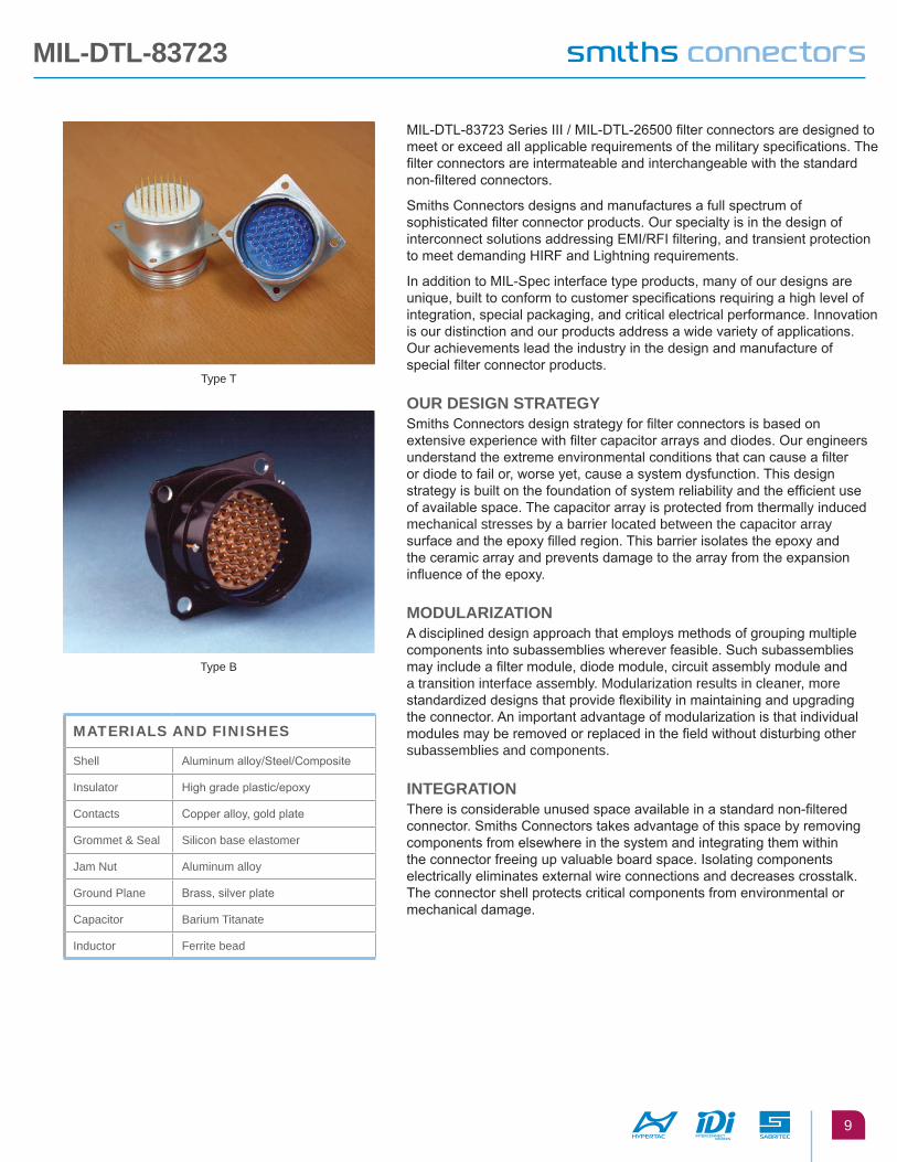
MIL-DTL-83723 Series III / MIL-DTL-26500 filter connectors are designed to meet or exceed all applicable requirements of the military specifications. The filter connectors are intermateable and interchangeable with the standard non-filtered connectors.
Smiths Connectors designs and manufactures a full spectrum of sophisticated filter connector products. Our specialty is in the design of interconnect solutions addressing EMI/RFI filtering, and transient protection to meet demanding HIRF and Lightning requirements.
In addition to MIL-Spec interface type products, many of our designs are unique, built to conform to customer specifications requiring a high level of integration, special packaging, and critical electrical performance. Innovation is our distinction and our products address a wide variety of applications. Our achievements lead the industry in the design and manufacture of special filter connector products.
ouR DesIgn stRategySmiths Connectors design strategy for filter connectors is based on extensive experience with filter capacitor arrays and diodes. Our engineers understand the extreme environmental conditions that can cause a filter or diode to fail or, worse yet, cause a system dysfunction. This design strategy is built on the foundation of system reliability and the efficient use of available space. The capacitor array is protected from thermally induced mechanical stresses by a barrier located between the capacitor array surface and the epoxy filled region. This barrier isolates the epoxy and the ceramic array and prevents damage to the array from the expansion influence of the epoxy.
MoDulaRIzatIonA disciplined design approach that employs methods of grouping multiple components into subassemblies wherever feasible. Such subassemblies may include a filter module, diode module, circuit assembly module and a transition interface assembly. Modularization results in cleaner, more standardized designs that provide flexibility in maintaining and upgrading the connector. An important advantage of modularization is that individual modules may be removed or replaced in the field without disturbing other subassemblies and components.
IntegRatIonThere is considerable unused space available in a standard non-filtered connector. Smiths Connectors takes advantage of this space by removing components from elsewhere in the system and integrating them within the connector freeing up valuable board space. Isolating components electrically eliminates external wire connections and decreases crosstalk. The connector shell protects critical components from environmental or mechanical damage.
Type B
Type T
MIl-Dtl-83723
MATERIALS AND FINISHES
Shell Aluminum alloy/Steel/Composite
Insulator High grade plastic/epoxy
Contacts Copper alloy, gold plate
Grommet & Seal Silicon base elastomer
Jam Nut Aluminum alloy
Ground Plane Brass, silver plate
Capacitor Barium Titanate
Inductor Ferrite bead

10
MIl-Dtl-83723
squaRe flange Receptacle - type b
JaM nut Receptacle - type b
F
See ContactTermination
X
±.010
±.010
.718
.062
L
K
J
1.400 MAXPi Filter
1.200 MAXC Filter
A Dia4 Holes
XGF
.371
U
V
W
1.400 MAXPi Filter
1.200 MAXC Filter
See ContactTermination
B
.125 MAX
±.010
.771
N
Smith Connectors provides specialty, enhanced performance connectors and cable assemblies and as such does not currently offer circular, rack and panel, or D-subminiature connectors that are listed on military standard Qualified Products Lists (QPL) per applicable detail specification sheets. Smith Connectors’ connectors are fully intermateable with applicable QPL products and meet the applicable requirements of all military standards listed in this catalog.
shell size
a Max
K bsc l J
Diaf
DiaX
Max Dia
8 .120 .594 .812 .561 .536 .531 .500
10 .120 .719 .937 .696 .659 .654 .620
12 .120 .812 1.031 .875 .829 .824 .740
14 .120 .906 1.125 .925 .898 .893 .890
16 .120 .969 1.250 1.062 1.025 1.020 1.000
18 .120 1.062 1.343 1.187 1.131 1.126 1.120
20 .120 1.156 1.437 1.312 1.256 1.251 1.250
22 .120 1.250 1.562 1.437 1.381 1.376 1.390
24 .149 1.375 1.703 1.562 1.506 1.501 1.500
shell size b f
Diag
Dian
thrd u V W X
8 .137 .097 .561 .536
.531 .625-20 .670 .979 1.068 .500
10 .137 .097 .696 .659
.654 .750-20 .796 1.104 1.192 .620
12 .113 .097 .875 .829
.824 .9375-20 .984 1.291 1.380 .740
14 .137 .097 .935 .898
.893 1.000-20 1.046 1.391 1.505 .890
16 .137 .097 1.062 1.025
1.020 1.125-20 1.171 1.516 1.630 1.00
18 .137 .097 1.187 1.131
1.126 1.250-18 1.296 1.641 1.756 1.120
20 .137 .097 1.312 1.256
1.251 1.375-18 1.484 1.766 1.860 1.250
22 .168 .128 1.437 1.381
1.376 1.500-18 1.609 1.954 2.068 1.390
24 .168 .128 1.562 1.506
1.501 1.625-18 1.734 2.079 2.160 1.500
11
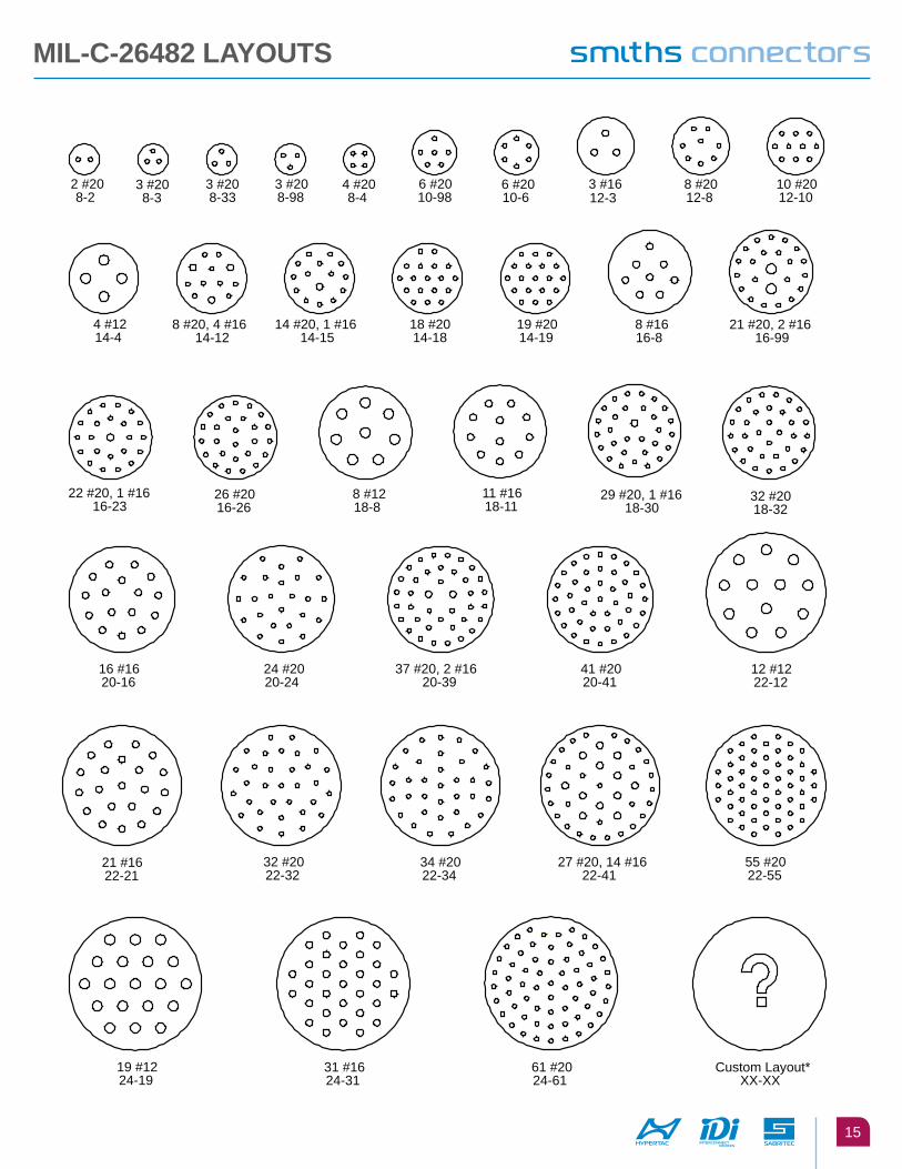
XX-XXCustom Layout*
37 #20, 2 #1620-39
12 #1222-12
41 #2020-41
19 #1622-19
55 #20, 2 #1224-57
26 #20, 6 #1222-32
27 #20, 12 #1622-39
55 #2022-55
23 #20, 20 #1624-43
61 #2024-61
2 #2010-2
5 #20 10-5
6 #2010-6 10-20
2 #16
24 #20, 4 #1220-28
19 #20, 6 #1220-25
16 #1620-16
14 #16 18-14
8 #12 18-8
10 #16 16-10
9 #20, 3 #16 14-12
7 #1614-7
4 #1214-4
2 #16, 1 #8 COAX14-3
3 #1612-3
3 #208-98
10 #16, 1 #8 COAX18-11
31 #20 18-3116-24
24 #20
15 #20 14-15
12 #2012-12
2 #208-2
3 #208-3
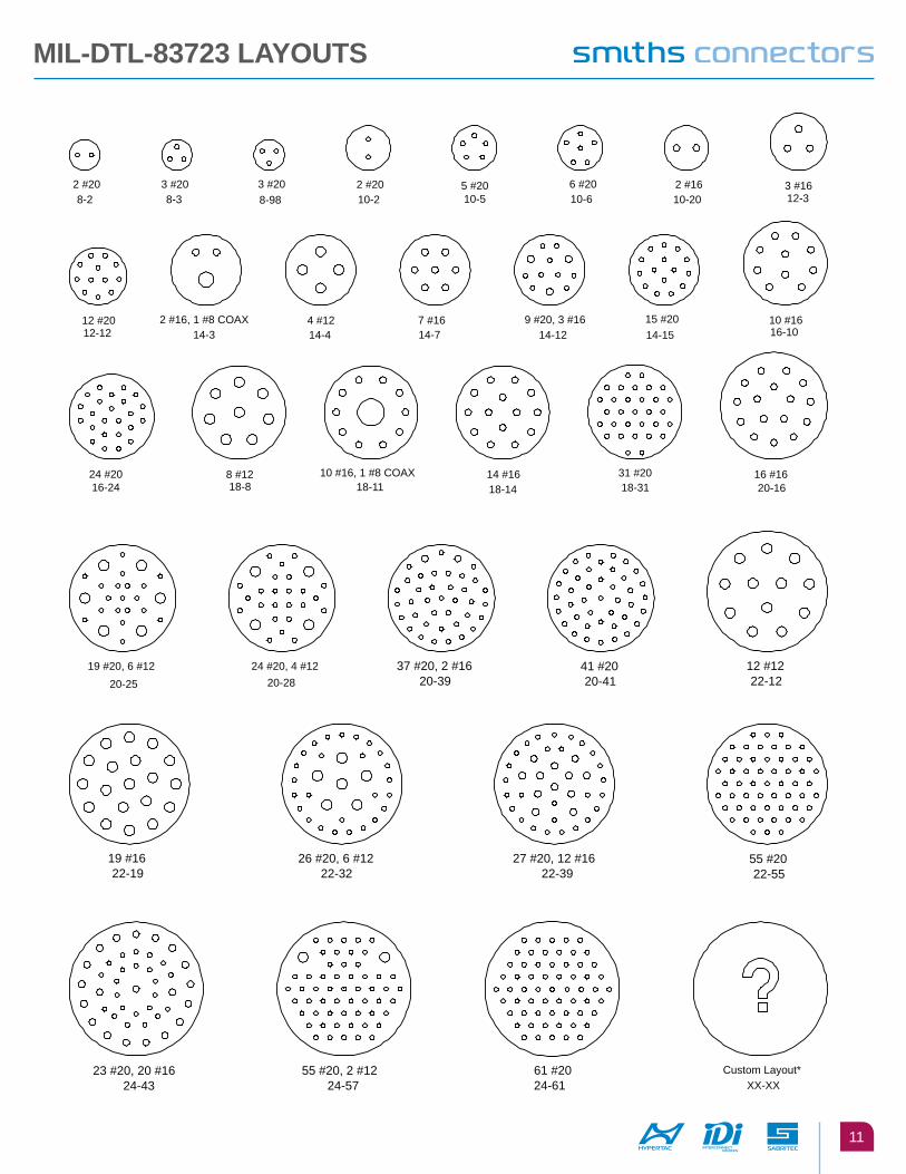
MIl-Dtl-83723 layouts
12
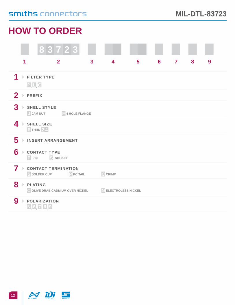
MIl-Dtl-83723
1 2 3 4 5 6 7 8 9
1 FILTER TYPE
pi, l, c
2 PREFIx
3 ShELL STYLE
J JaM nut f 4 Hole flange
4 ShELL SIZE
8 tHRu 2 4
5 INSERT aRRaNGEMENT
6 CONTaCT TYPE
p pIn s socKet
7 CONTaCT TERMINaTION
s solDeR cup p pc taIl c cRIMp
8 PLaTING
c olIVe DRab caDMIuM oVeR nIcKel n electRoless nIcKel
9 POLaRIZaTION
n, 6 , 7 , 8 , 9
HoW to oRDeR
8 7 2 33

13
MIL-C-26482 Series II / MIL-DTL-83723 Series I filter connectors are designed to meet or exceed all applicable requirements of the military specifications. The filter connectors are intermateable and interchangeable with the standard non-filtered connectors.
Smiths Connectors designs and manufactures a full spectrum of sophisticated filter connector products. Our specialty is in the design of interconnect solutions addressing EMI/RFI filtering, and transient protection to meet demanding HIRF and Lightning requirements.
In addition to MIL-Spec interface type products, many of our designs are unique, built to conform to customer specifications requiring a high level of integration, special packaging, and critical electrical performance. Innovation is our distinction and our products address a wide variety of applications. Our achievements lead the industry in the design and manufacture of special filter connector products.
ouR DesIgn stRategySmiths Connectors design strategy for filter connectors is based on extensive experience with filter capacitor arrays and diodes. Our engineers understand the extreme environmental conditions that can cause a filter or diode to fail or, worse yet, cause a system dysfunction. This design strategy is built on the foundation of system reliability and the efficient use of available space. The capacitor array is protected from thermally induced mechanical stresses by a barrier located between the capacitor array surface and the epoxy filled region. This barrier isolates the epoxy and the ceramic array and prevents damage to the array from the expansion influence of the epoxy.
MoDulaRIzatIonA disciplined design approach that employs methods of grouping multiple components into subassemblies wherever feasible. Such subassemblies may include a filter module, diode module, circuit assembly module and a transition interface assembly. Modularization results in cleaner, more standardized designs that provide flexibility in maintaining and upgrading the connector. An important advantage of modularization is that individual modules may be removed or replaced in the field without disturbing other subassemblies and components.
IntegRatIonThere is considerable unused space available in a standard non-filtered connector. Smiths Connectors takes advantage of this space by removing components from elsewhere in the system and integrating them within the connector freeing up valuable board space. Isolating components electrically eliminates external wire connections and decreases crosstalk. The connector shell protects critical components from environmental or mechanical damage.
MIl-c-26482
MATERIALS AND FINISHES
Shell Aluminum alloy
Insulator High grade plastic/epoxy
Contacts Copper alloy, gold plate
Grommet & Seal Silicon base elastomer
Jam Nut Aluminum alloy
Ground Plane Brass, silver plate
Capacitor Barium Titanate
Inductor Ferrite bead

14
Ms3474 JaM nut Receptacle
Ms3470 squaRe flange Receptacle
H Dia4 Holes
See ContactTermination
X
GF
A Max
B
1.400 MAXPi Filter
1.200 MAXC Filter
T
T
G
N
F
**
AA
1.400 MAXPi Filter
1.200 MAXC Filter
A
O Flat
B dia
.250 Max Shell Size 20-24**.187 Max Shell Size 8-18
See ContactTermination
X
Smith Connectors provides specialty, enhanced performance connectors and cable assemblies and as such does not currently offer circular, rack and panel, or D-subminiature connectors that are listed on military standard Qualified Products Lists (QPL) per applicable detail specification sheets. Smith Connectors’ connectors are fully intermateable with applicable QPL products and meet the applicable requirements of all military standards listed in this catalog.
MIl-c-26482
shell size
a Max
b bsc f g
DiaH
Diat
Max
X Max Dia
8 .828 .594
.462
.431.078 .046
.120
.474
.468 .500
10 .954 .719 .591 .585 .620
12 1.047 .812 .751 .745 .740
14 1.141 .906 .876 .870 .890
16 1.231 .969 1.001 .995 1.000
18 1.328 1.062 1.126 1.120 1.120
20 1.458 1.156 .587.110
1.251 1.245 1.250
22 1.578 1.250 .556 1.376 1.370 1.390
24 1.703 1.375 .620 .589 .078 .147 1.501
1.495 1.500
shell size
a Max
b Dia f g
Dia no
1.005 flat
t Dia
X Max Dia
aa Hex Dia
8 .954 .923
1.078 1.047
.707
.658.113 .086
.5625-24 .525 4.74 4.68 .500 0.787
10 1.078 1.047
1.203 1.172 .6875-24 .650 .591
.585 .620 0.892
12 1.266 1.235
1.391 1.360 .875-20 .813 .751
.745 .740 1.079
14 1.391 1.360
1.516 1.485 1.000-20 .937 .876
.870 .890 1.205
16 1.516 1.485
1.641 1.610 1.125-18 1.061 1.001
.995 1.00 1.329
18 1.641 1.610
1.766 1.735 1.120-18 1.166 1.126
1.120 1.120 1.455
20 1.828 .797
1.9541.923
.772
.721.148 .096
1.375-18 1.311 1.251 1.245 1.250 1.579
22 1.9541.923
2.0782.047 1.500-18 1.436 1.376
1.370 1.390 1.705
24 2.0782.047
2.2032.172 1.625-18 1.561 1.501
1.495 1.500 1.829
15
2 #208-2
3 #208-3
3 #208-33
3 #208-98
4 #208-4
6 #2010-98
6 #2010-6
3 #1612-3
8 #2012-8
10 #2012-10
4 #1214-4
8 #20, 4 #1614-12
14 #20, 1 #1614-15
18 #2014-18
19 #2014-19
8 #1616-8
21 #20, 2 #1616-99
22 #20, 1 #1616-23
26 #2016-26
8 #1218-8
11 #1618-11
29 #20, 1 #1618-30
32 #2018-32
XX-XXCustom Layout*
16 #1620-16
24 #2020-24
27 #20, 14 #1622-41
55 #2022-55
37 #20, 2 #1620-39
41 #2020-41
19 #1224-19
31 #1624-31
12 #1222-12
21 #1622-21
61 #2024-61
32 #2022-32
34 #2022-34
MIl-c-26482 layouts

16
MIl-c-26482
1 2 3 4 5 6 7 8 9
1 FILTER TYPE
pi, l, c
2 PREFIx
3 ShELL STYLE
J JaM nut b boX Mount W Wall Mount
4 ShELL SIZE
8 tHRu 2 4
5 INSERT aRRaNGEMENT
6 CONTaCT TYPE
p pIn s socKet
7 CONTaCT TERMINaTION
s solDeR cup p pc taIl c cRIMp
8 PLaTING
c olIVe DRab caDMIuM oVeR nIcKel n electRoless nIcKel
9 POLaRIZaTION
n, W, X, y, z
HoW to oRDeR
2 4 8 26

17
electRIcal cHaRacteRIstIcs - 'pI' sectIon
InseRtIon loss table
FILTER DESCRIPTION P200 P100 P76 P38 P20 P10 P8 P4 P2 P1
Operating Temperature Range -55°C to + 125°C
Voltage Rating 100 VDC 200 VDC-120 Vrms 400 Hz
Current Rating DC 15 amps size 16/7.5 amps size 20/5 amps size 22
Insulation Resistance 5000 megohms min. @100 VDC
Current Rating R.F. 3.0 amps max.
DWV Sea Level w/ 50 micro-amps max. charge/discharge 250 VDC 500 VDC
FILTER DESCRIPTION SEE NOTES P200 P100 P76 P38 P20 P10 P8 P4 P2 P1
Capacitance in Nanofarads @ 1Khz,. 1VRMS
160240
80120
6091
3046
1624
812
6.49.2
3.24.8
1.62.4
.81.2
Minimum No Attenuation loss @ 25°
Freq Mhz
.1 8 4.1 3 1 .3 .1 - - - -
1.0 22.2 19.6 18.2 13.3 8.2 3.9 2.9 .9 .2 -
2 32.8 21.7 19.7 16.8 12.7 8 6.6 2.9 1 .3
10 73.5 61 57 44.4 31.5 20.6 18.3 12.8 8.1 4.0
100 85+ 85+ 85+ 85+ 78 65.8 61.9 49.6 37.3 25.6
500-1k 85+ 85+ 85+ 85+ 85+ 85+ 80 75 64 52
'pI' sectIon cuRVesC1 C2
L R
Ferrite Bead
Notes:1. P200 & P100 Capacitance Values for Size 20 Contact Arrangement & Larger2. No Load Minimum Attenuation Values per MIL-STD-2203. Capacitance in Nanofarads (Nominal Value)4. Consult Factory for Higher Voltages & Capacitance Values
electRIcal peRfoRMance
18
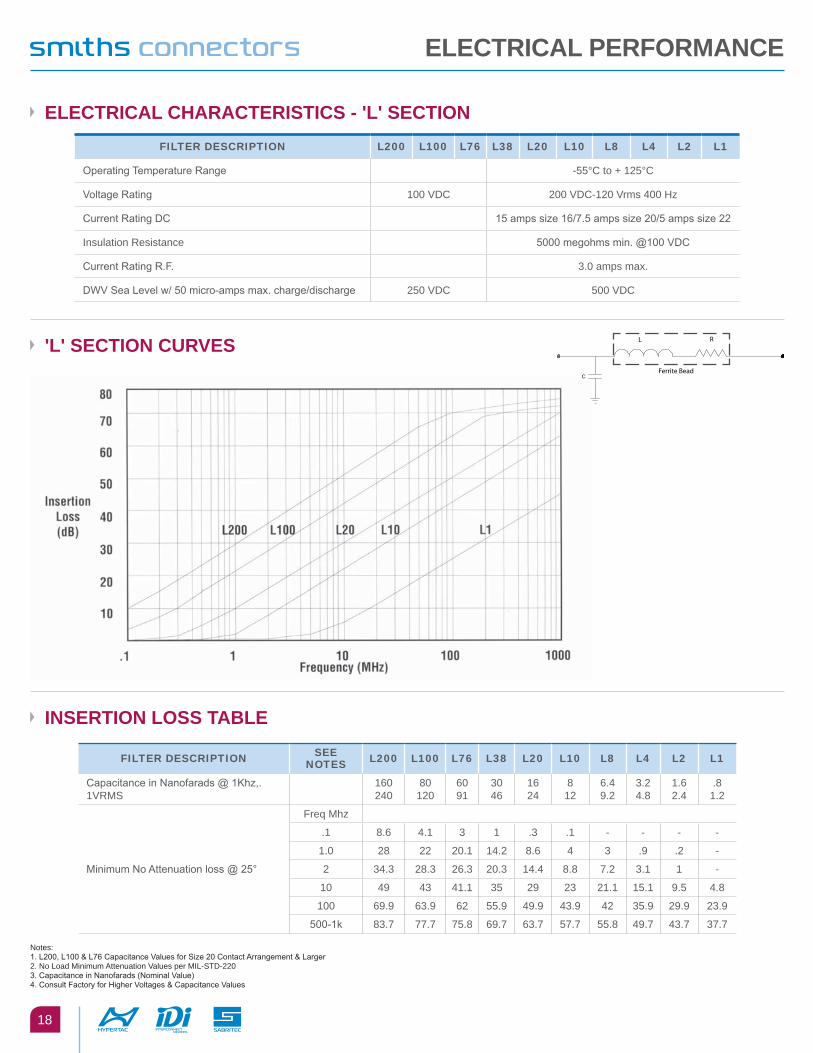
InseRtIon loss table
electRIcal cHaRacteRIstIcs - 'l' sectIonFILTER DESCRIPTION L200 L100 L76 L38 L20 L10 L8 L4 L2 L1
Operating Temperature Range -55°C to + 125°C
Voltage Rating 100 VDC 200 VDC-120 Vrms 400 Hz
Current Rating DC 15 amps size 16/7.5 amps size 20/5 amps size 22
Insulation Resistance 5000 megohms min. @100 VDC
Current Rating R.F. 3.0 amps max.
DWV Sea Level w/ 50 micro-amps max. charge/discharge 250 VDC 500 VDC
FILTER DESCRIPTION SEE NOTES L200 L100 L76 L38 L20 L10 L8 L4 L2 L1
Capacitance in Nanofarads @ 1Khz,. 1VRMS
160240
80120
6091
3046
1624
812
6.49.2
3.24.8
1.62.4
.81.2
Minimum No Attenuation loss @ 25°
Freq Mhz
.1 8.6 4.1 3 1 .3 .1 - - - -
1.0 28 22 20.1 14.2 8.6 4 3 .9 .2 -
2 34.3 28.3 26.3 20.3 14.4 8.8 7.2 3.1 1 -
10 49 43 41.1 35 29 23 21.1 15.1 9.5 4.8
100 69.9 63.9 62 55.9 49.9 43.9 42 35.9 29.9 23.9
500-1k 83.7 77.7 75.8 69.7 63.7 57.7 55.8 49.7 43.7 37.7
'l' sectIon cuRVes L R
Ferrite BeadC
electRIcal peRfoRMance
Notes:1. L200, L100 & L76 Capacitance Values for Size 20 Contact Arrangement & Larger2. No Load Minimum Attenuation Values per MIL-STD-2203. Capacitance in Nanofarads (Nominal Value)4. Consult Factory for Higher Voltages & Capacitance Values
19
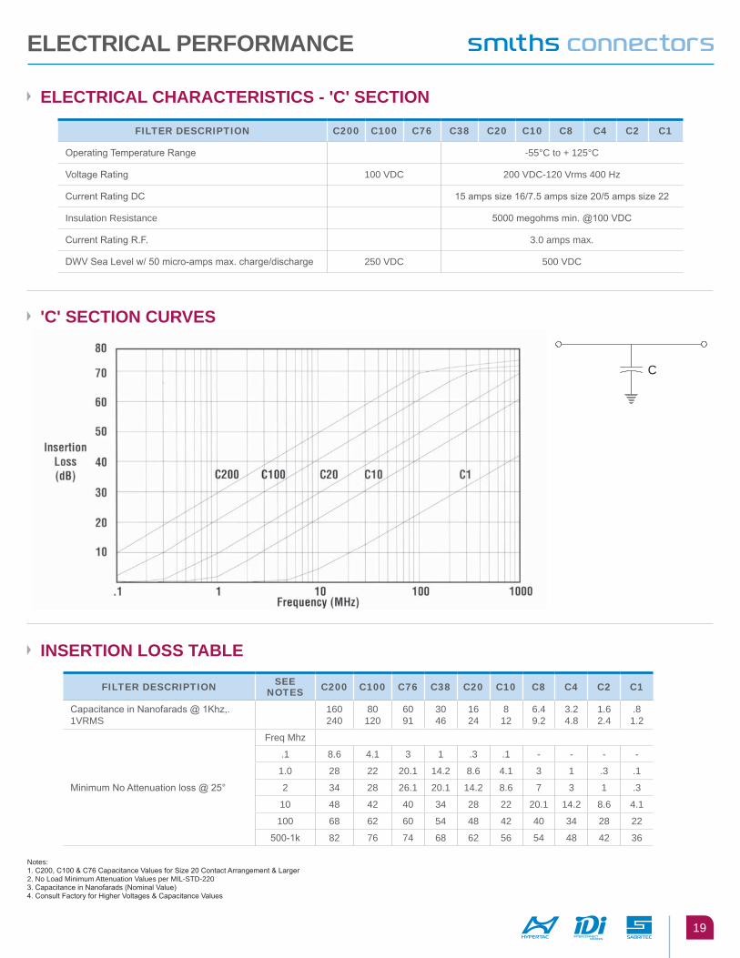
Notes:1. C200, C100 & C76 Capacitance Values for Size 20 Contact Arrangement & Larger2. No Load Minimum Attenuation Values per MIL-STD-2203. Capacitance in Nanofarads (Nominal Value)4. Consult Factory for Higher Voltages & Capacitance Values
'c' sectIon cuRVes
InseRtIon loss table
electRIcal cHaRacteRIstIcs - 'c' sectIon
C
FILTER DESCRIPTION C200 C100 C76 C38 C20 C10 C8 C4 C2 C1
Operating Temperature Range -55°C to + 125°C
Voltage Rating 100 VDC 200 VDC-120 Vrms 400 Hz
Current Rating DC 15 amps size 16/7.5 amps size 20/5 amps size 22
Insulation Resistance 5000 megohms min. @100 VDC
Current Rating R.F. 3.0 amps max.
DWV Sea Level w/ 50 micro-amps max. charge/discharge 250 VDC 500 VDC
FILTER DESCRIPTION SEE NOTES C200 C100 C76 C38 C20 C10 C8 C4 C2 C1
Capacitance in Nanofarads @ 1Khz,. 1VRMS
160240
80120
6091
3046
1624
812
6.49.2
3.24.8
1.62.4
.81.2
Minimum No Attenuation loss @ 25°
Freq Mhz
.1 8.6 4.1 3 1 .3 .1 - - - -
1.0 28 22 20.1 14.2 8.6 4.1 3 1 .3 .1
2 34 28 26.1 20.1 14.2 8.6 7 3 1 .3
10 48 42 40 34 28 22 20.1 14.2 8.6 4.1
100 68 62 60 54 48 42 40 34 28 22
500-1k 82 76 74 68 62 56 54 48 42 36
electRIcal peRfoRMance
20
peRfoRMance Data
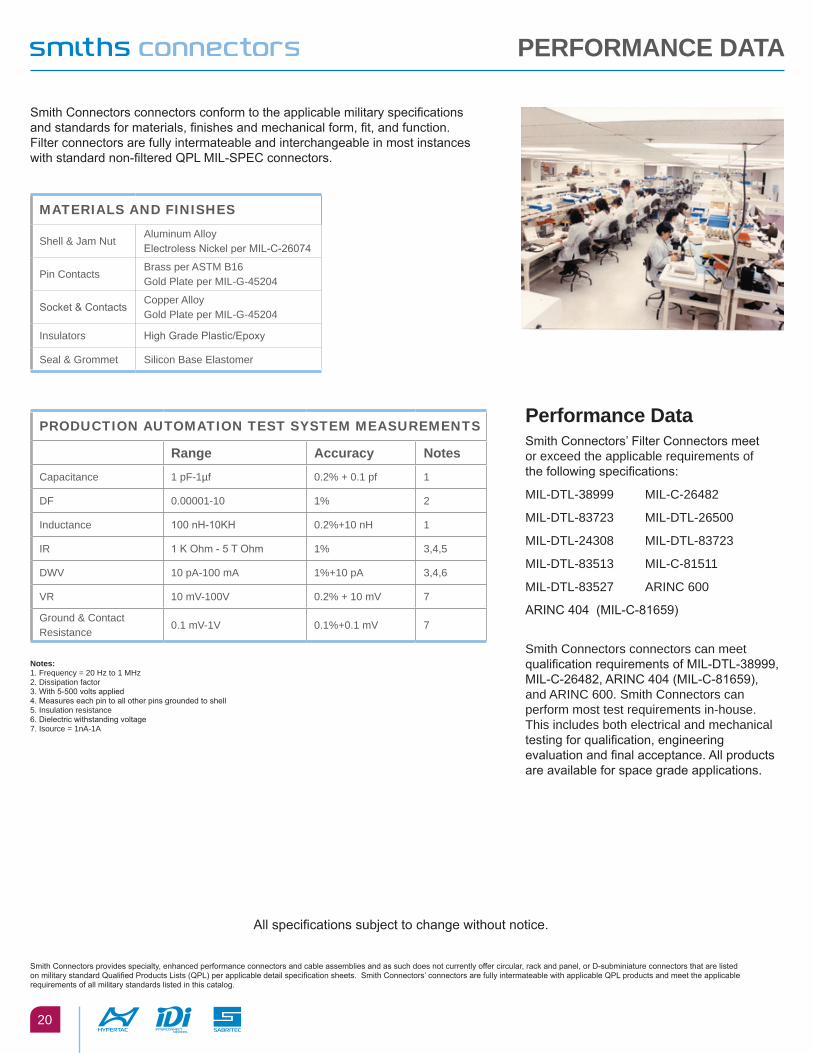
Smith Connectors connectors conform to the applicable military specifications and standards for materials, finishes and mechanical form, fit, and function. Filter connectors are fully intermateable and interchangeable in most instances with standard non-filtered QPL MIL-SPEC connectors.
performance DataSmith Connectors’ Filter Connectors meet or exceed the applicable requirements of the following specifications:
MIL-DTL-38999 MIL-C-26482
MIL-DTL-83723 MIL-DTL-26500
MIL-DTL-24308 MIL-DTL-83723
MIL-DTL-83513 MIL-C-81511
MIL-DTL-83527 ARINC 600
ARINC 404 (MIL-C-81659)
Smith Connectors connectors can meet qualification requirements of MIL-DTL-38999, MIL-C-26482, ARINC 404 (MIL-C-81659), and ARINC 600. Smith Connectors can perform most test requirements in-house. This includes both electrical and mechanical testing for qualification, engineering evaluation and final acceptance. All products are available for space grade applications.
PRODUCTION AUTOMATION TEST SYSTEM MEASUREMENTS
Range accuracy notesCapacitance 1 pF-1µf 0.2% + 0.1 pf 1
DF 0.00001-10 1% 2
Inductance 100 nH-10KH 0.2%+10 nH 1
IR 1 K Ohm - 5 T Ohm 1% 3,4,5
DWV 10 pA-100 mA 1%+10 pA 3,4,6
VR 10 mV-100V 0.2% + 10 mV 7
Ground & Contact Resistance
0.1 mV-1V 0.1%+0.1 mV 7
All specifications subject to change without notice.
Smith Connectors provides specialty, enhanced performance connectors and cable assemblies and as such does not currently offer circular, rack and panel, or D-subminiature connectors that are listed on military standard Qualified Products Lists (QPL) per applicable detail specification sheets. Smith Connectors’ connectors are fully intermateable with applicable QPL products and meet the applicable requirements of all military standards listed in this catalog.
MATERIALS AND FINISHES
Shell & Jam NutAluminum Alloy Electroless Nickel per MIL-C-26074
Pin ContactsBrass per ASTM B16 Gold Plate per MIL-G-45204
Socket & ContactsCopper Alloy Gold Plate per MIL-G-45204
Insulators High Grade Plastic/Epoxy
Seal & Grommet Silicon Base Elastomer
notes: 1. Frequency = 20 Hz to 1 MHz2. Dissipation factor3. With 5-500 volts applied4. Measures each pin to all other pins grounded to shell5. Insulation resistance6. Dielectric withstanding voltage7. Isource = 1nA-1A
21
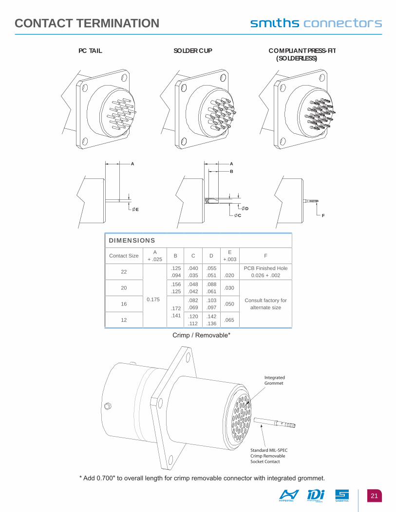
contact teRMInatIon
Crimp / Removable*
* Add 0.700" to overall length for crimp removable connector with integrated grommet.
PC TAIL SOLDER CUP COMPLIANT PRESS-FIT(SOLDERLESS)
A
E
A
B
C
D
F
Integrated Grommet
Standard MIL-SPEC Crimp Removable Socket Contact
DIMENSIONS
Contact SizeA
+ .025B C D
E +.003
F
22
0.175
.125
.094.040 .035
.055
.051 .020
PCB Finished Hole 0.026 + .002
20.156 .125
.048
.042.088 .061
.030
Consult factory for alternate size
16.172 .141
.082
.069.103 .097
.050
12.120 .112
.142
.136.065
22
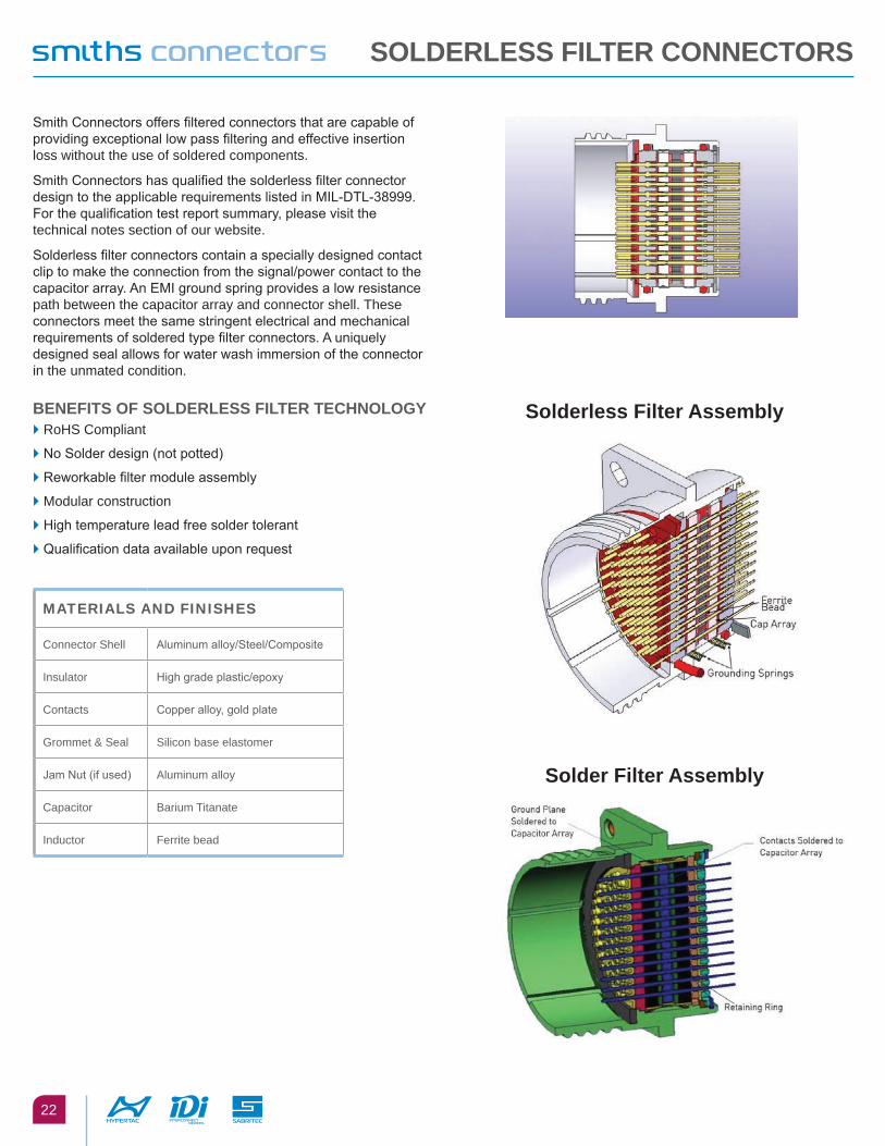
Smith Connectors offers filtered connectors that are capable of providing exceptional low pass filtering and effective insertion loss without the use of soldered components.
Smith Connectors has qualified the solderless filter connector design to the applicable requirements listed in MIL-DTL-38999. For the qualification test report summary, please visit the technical notes section of our website.
Solderless filter connectors contain a specially designed contact clip to make the connection from the signal/power contact to the capacitor array. An EMI ground spring provides a low resistance path between the capacitor array and connector shell. These connectors meet the same stringent electrical and mechanical requirements of soldered type filter connectors. A uniquely designed seal allows for water wash immersion of the connector in the unmated condition.
benefIts of solDeRless fIlteR tecHnology► RoHS Compliant
► No Solder design (not potted)
► Reworkable filter module assembly
► Modular construction
► High temperature lead free solder tolerant
► Qualification data available upon request
solderless filter assembly
solder filter assembly
solDeRless fIlteR connectoRs
MATERIALS AND FINISHES
Connector Shell Aluminum alloy/Steel/Composite
Insulator High grade plastic/epoxy
Contacts Copper alloy, gold plate
Grommet & Seal Silicon base elastomer
Jam Nut (if used) Aluminum alloy
Capacitor Barium Titanate
Inductor Ferrite bead

23
Non–filter applications can easily be upgraded to EMI/Transient protection without modification to the system with Smith Connectors’ In–Line Filter Adapters. Filter adapters provide the system designer great flexibility in situations where the filtering or system requirements are subject to change. The adapters are designed to be installed between the existing plug and receptacle without having to re–wire or disassemble the system. Both in–line cable and bulkhead/panel mount versions are available. Adapters can be built for any connector series including MIL-DTL-38999, MIL–C–26482, MIL–DTL–83723, MIL-DTL–24308, MIL–DTL–83513, ARINC 404, and ARINC 600. Consult the factory for more information.
MIl-Dtl-38999 series III adapter
MIl-Dtl-24308 D-subminiature adapter
MIl-Dtl-38999 series I adapter
fIlteR aDapteRs
SMITHS CONNECTORSGLOBAL SUPPORT
AMERICAS EUROPE [email protected]
Costa Mesa, CA 1.714.371.1100
Hudson, MA 1.978.568.0451
Kansas City, KS 1.913.342.5544
France [email protected]
Germany [email protected]
Italy [email protected]
United Kingdom [email protected]
Shanghai, China 86.21.3318.4650
Suzhou, China 86.512.6273.1188
Singapore 65.6846.1655
visit us at | smithsconnectors.com |
Copyright© 2016 Smiths Connectors | All rights reserved | Version 1.1