Download - Balancing Valves 08.16
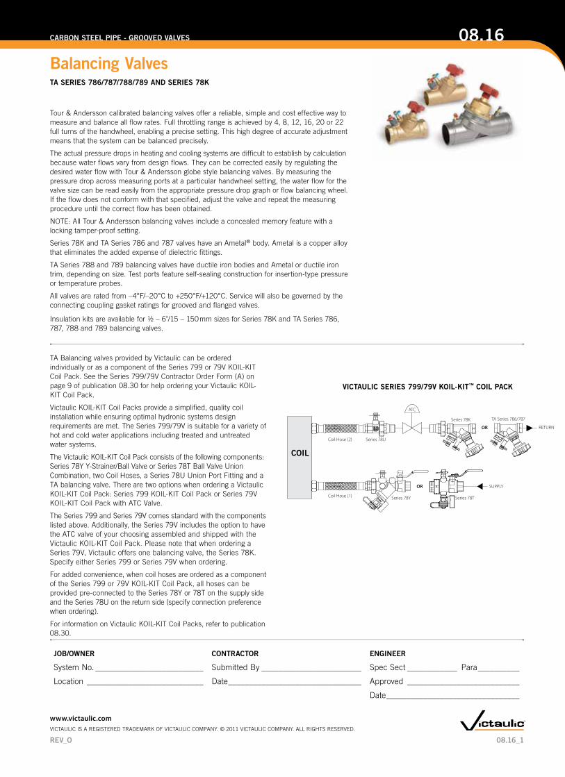
Tour & Andersson calibrated balancing valves offer a reliable, simple and cost effective way to measure and balance all flow rates. Full throttling range is achieved by 4, 8, 12, 16, 20 or 22 full turns of the handwheel, enabling a precise setting. This high degree of accurate adjustment means that the system can be balanced precisely.
The actual pressure drops in heating and cooling systems are difficult to establish by calculation because water flows vary from design flows. They can be corrected easily by regulating the desired water flow with Tour & Andersson globe style balancing valves. By measuring the pressure drop across measuring ports at a particular handwheel setting, the water flow for the valve size can be read easily from the appropriate pressure drop graph or flow balancing wheel. If the flow does not conform with that specified, adjust the valve and repeat the measuring procedure until the correct flow has been obtained.
NOTE: All Tour & Andersson balancing valves include a concealed memory feature with a locking tamper-proof setting.
Series 78K and TA Series 786 and 787 valves have an Ametal® body. Ametal is a copper alloy that eliminates the added expense of dielectric fittings.
TA Series 788 and 789 balancing valves have ductile iron bodies and Ametal or ductile iron trim, depending on size. Test ports feature self-sealing construction for insertion-type pressure or temperature probes.
All valves are rated from –4°F/–20°C to +250°F/+120°C. Service will also be governed by the connecting coupling gasket ratings for grooved and flanged valves. Insulation kits are available for 1/2 – 6"/15 – 150 mm sizes for Series 78K and TA Series 786, 787, 788 and 789 balancing valves.
TA Balancing valves provided by Victaulic can be ordered individually or as a component of the Series 799 or 79V KOIL-KIT Coil Pack. See the Series 799/79V Contractor Order Form (A) on page 9 of publication 08.30 for help ordering your Victaulic KOIL-KIT Coil Pack.
Victaulic KOIL-KIT Coil Packs provide a simplified, quality coil installation while ensuring optimal hydronic systems design requirements are met. The Series 799/79V is suitable for a variety of hot and cold water applications including treated and untreated water systems.
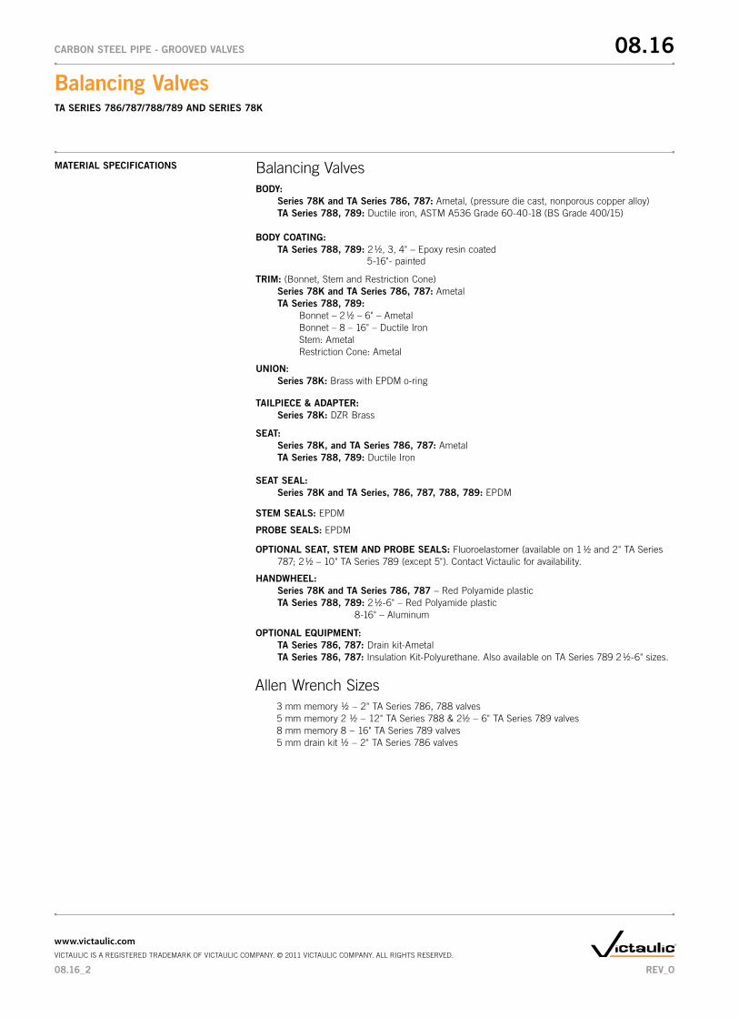
The Victaulic KOIL-KIT Coil Pack consists of the following components: Series 78Y Y-Strainer/Ball Valve or Series 78T Ball Valve Union Combination, two Coil Hoses, a Series 78U Union Port Fitting and a TA balancing valve. There are two options when ordering a Victaulic KOIL-KIT Coil Pack: Series 799 KOIL-KIT Coil Pack or Series 79V KOIL-KIT Coil Pack with ATC Valve.
The Series 799 and Series 79V comes standard with the components listed above. Additionally, the Series 79V includes the option to have the ATC valve of your choosing assembled and shipped with the Victaulic KOIL-KIT Coil Pack. Please note that when ordering a Series 79V, Victaulic offers one balancing valve, the Series 78K. Specify either Series 799 or Series 79V when ordering.
For added convenience, when coil hoses are ordered as a component of the Series 799 or 79V KOIL-KIT Coil Pack, all hoses can be provided pre-connected to the Series 78Y or 78T on the supply side and the Series 78U on the return side (specify connection preference when ordering).
For information on Victaulic KOIL-KIT Coil Packs, refer to publication 08.30.
ATC
OR
OR
SUPPLY
RETURN
Series 78UCoil Hose (2)
Coil Hose (1)
TA Series 786/787Series 78K
Series 78Y Series 78T
COIL
VICTAULIC SERIES 799/79V KOIL-KIT™ COIL PACK
08.16_1
Balancing Valves TA SERIES 786/787/788/789 And SERIES 78K
08.16CARBOn STEEL PIPE - GROOVEd VALVES
JOB/OWnER COnTRACTOR EnGInEER
System No. __________________________ Submitted By ________________________ Spec Sect ____________ Para __________
Location ____________________________ Date ________________________________ Approved ___________________________
Date ________________________________
www.victaulic.comVICTAULIC IS A REGISTERED TRADEMARK OF VICTAULIC COMPANY. © 2011 VICTAULIC COMPANY. ALL RIGHTS RESERVED.
REV_O
MATERIAL SPECIFICATIOnS Balancing ValvesBOdY:
Series 78K and TA Series 786, 787: Ametal, (pressure die cast, nonporous copper alloy)TA Series 788, 789: Ductile iron, ASTM A536 Grade 60-40-18 (BS Grade 400/15)
BOdY COATInG:TA Series 788, 789: 2 1/2, 3, 4" – Epoxy resin coated 5-16"- painted
TRIM: (Bonnet, Stem and Restriction Cone)Series 78K and TA Series 786, 787: AmetalTA Series 788, 789: Bonnet – 2 1/2 – 6" – Ametal Bonnet – 8 – 16" – Ductile Iron Stem: Ametal Restriction Cone: Ametal
UnIOn:Series 78K: Brass with EPDM o-ring
Allen Wrench Sizes3 mm memory 1/2 − 2" TA Series 786, 788 valves5 mm memory 2 1/2 − 12" TA Series 788 & 21/2 − 6" TA Series 789 valves8 mm memory 8 − 16" TA Series 789 valves5 mm drain kit 1/2 − 2" TA Series 786 valves
TAILPIECE & AdAPTER:Series 78K: DZR Brass
SEAT:Series 78K, and TA Series 786, 787: AmetalTA Series 788, 789: Ductile Iron
SEAT SEAL:Series 78K and TA Series, 786, 787, 788, 789: EPDM
STEM SEALS: EPDM
PROBE SEALS: EPDM
OPTIOnAL SEAT, STEM And PROBE SEALS: Fluoroelastomer (available on 1 1/2 and 2" TA Series787; 2 1/2 – 10" TA Series 789 (except 5"). Contact Victaulic for availability.
HAndWHEEL:Series 78K and TA Series 786, 787 – Red Polyamide plasticTA Series 788, 789: 2 1/2-6" – Red Polyamide plastic 8-16" – Aluminum
OPTIOnAL EQUIPMEnT:TA Series 786, 787: Drain kit-AmetalTA Series 786, 787: Insulation Kit-Polyurethane. Also available on TA Series 789 2 1/2-6" sizes.
08.16_2
Balancing Valves TA SERIES 786/787/788/789 And SERIES 78K
08.16CARBOn STEEL PIPE - GROOVEd VALVES
www.victaulic.comVICTAULIC IS A REGISTERED TRADEMARK OF VICTAULIC COMPANY. © 2011 VICTAULIC COMPANY. ALL RIGHTS RESERVED.
REV_O
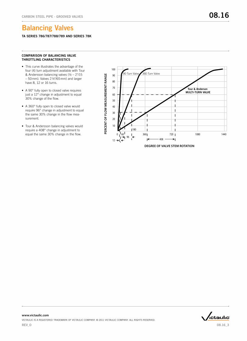
COMPARISOn OF BALAnCInG VALVE THROTTLInG CHARACTERISTICS
• Thiscurveillustratestheadvantageofthefour (4) turn adjustment available with Tour & Andersson balancing valves (1/2 – 2"/15 – 50 mm). Valves 2 1/2"/65 mm) and larger have 8, 12 or 16 turns.
• A90°fullyopentoclosedvalverequiresjust a 12° change in adjustment to equal 30% change of the flow.
• A360°fullyopentoclosedvalvewouldrequire 96° change in adjustment to equal the same 30% change in the flow mea-surement.
• Tour&Anderssonbalancingvalveswouldrequire a 408° change in adjustment to equal the same 30% change in the flow. 1440
10
20
30
60
50
40
70
80
90
100
180
0 60 360 720 1080
1296
408
Tour & Anderson MULTI-TURN VALVE
90 Turn Valve 360 Turn Valve
DEGREE OF VALVE STEM ROTATION
PERC
ENT
OF
FLO
W M
EASU
REM
ENT
RAN
GE
08.16_3
Balancing Valves TA SERIES 786/787/788/789 And SERIES 78K
08.16CARBOn STEEL PIPE - GROOVEd VALVES
www.victaulic.comVICTAULIC IS A REGISTERED TRADEMARK OF VICTAULIC COMPANY. © 2011 VICTAULIC COMPANY. ALL RIGHTS RESERVED.
REV_O
SizeTA Series 786 Solder End (300 psi/2065 kPa)
Balancing ValveTA Series 787 nPT (Female) Threaded End
(300 psi/2065 kPa) Balancing Valve
nominal Size
Inches/mm
Actual Outside dia. Inches/mm
A End to End Inches/mm
B Center to Top Inches/mm
Approx. Weight Each
Lbs./kg
A End to End Inches/mm
B Center to Top Inches/mm
Approx. Weight Each
Lbs./kg
1/2 0.840 3.50 4.00 1.4 3.50 4.00 1.515 21.3 89 102 0.6 89 102 0.7
3/4 1.050 3.81 4.00 1.4 3.81 4.00 1.620 26.7 97 102 0.6 97 102 0.7
1 1.315 4.31 4.50 1.9 4.31 4.50 2.025 33.7 110 114 0.9 110 114 0.9
1 1/4 1.660 4.88 4.31 2.4 4.88 4.31 2.632 42.4 124 110 1.1 124 110 1.2
1 1/2 1.900 5.13 4.75 3.1 5.13 4.75 3.340 48.3 130 121 1.4 130 121 1.5
2 2.375 6.13 4.75 4.5 6.13 4.75 5.050 60.3 156 121 2.0 156 121 2.3
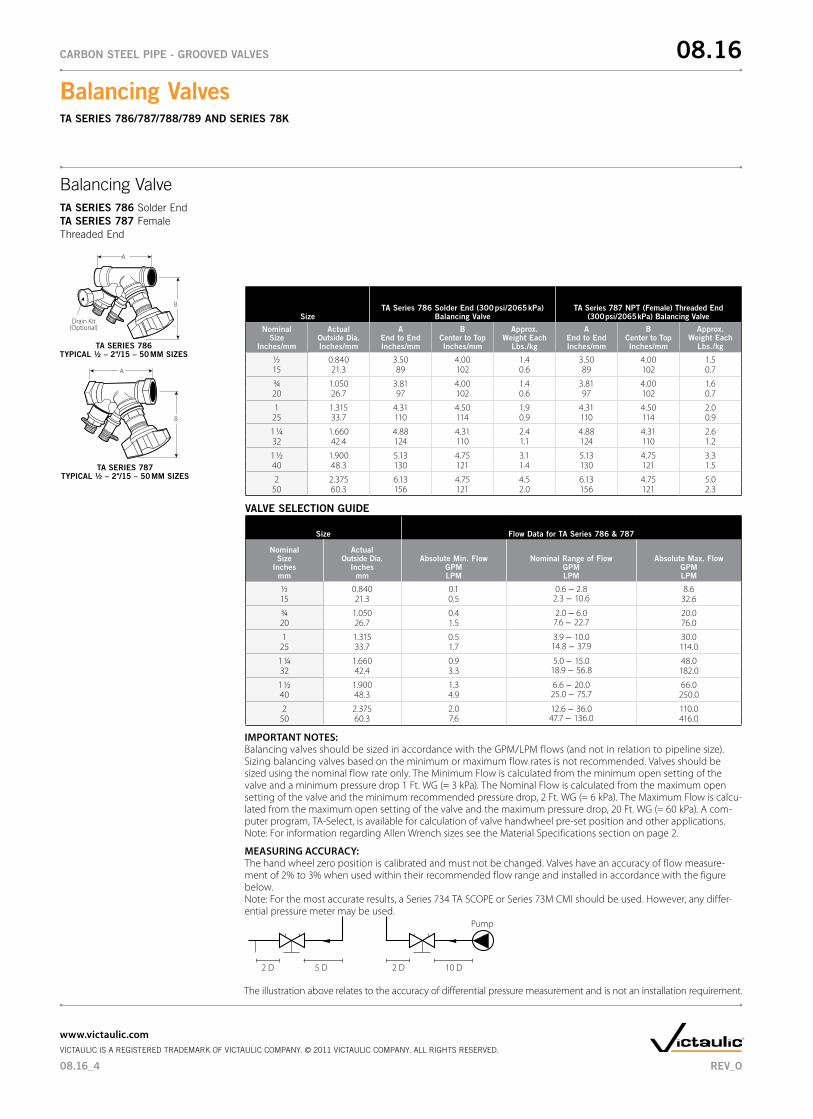
Balancing ValveTA SERIES 786 Solder EndTA SERIES 787 Female Threaded End
IMPORTANT NOTES: Balancing valves should be sized in accordance with the GPM/LPM flows (and not in relation to pipeline size). Sizing balancing valves based on the minimum or maximum flow rates is not recommended. Valves should be sized using the nominal flow rate only. The Minimum Flow is calculated from the minimum open setting of the valve and a minimum pressure drop 1 Ft. WG (= 3 kPa). The Nominal Flow is calculated from the maximum open setting of the valve and the minimum recommended pressure drop, 2 Ft. WG (= 6 kPa). The Maximum Flow is calcu-lated from the maximum open setting of the valve and the maximum pressure drop, 20 Ft. WG (= 60 kPa). A com-puter program, TA-Select, is available for calculation of valve handwheel pre-set position and other applications. Note: For information regarding Allen Wrench sizes see the Material Specifications section on page 2.
A
B
SERIES 786
TA SERIES 786TYPICAL ½ – 2"/15 – 50 MM SIZES
A
B
Drain Kit(Optional)
TA SERIES 787TYPICAL ½ – 2"/15 – 50 MM SIZES
Size Flow data for TA Series 786 & 787
nominal Size
Inches mm
Actual Outside dia.
Inches mm
Absolute Min. Flow GPM LPM
nominal Range of FlowGPMLPM
Absolute Max. Flow GPM LPM
1/2 0.840 0.1 0.6 − 2.82.3 − 10.6
8.615 21.3 0.5 32.6
3/4 1.050 0.4 2.0 − 6.07.6 − 22.7
20.020 26.7 1.5 76.0
1 1.315 0.5 3.9 − 10.014.8 − 37.9
30.025 33.7 1.7 114.0
1 1/4 1.660 0.9 5.0 − 15.018.9 − 56.8
48.032 42.4 3.3 182.0
1 1/2 1.900 1.3 6.6 − 20.025.0 − 75.7
66.040 48.3 4.9 250.0
2 2.375 2.0 12.6 − 36.047.7 − 136.0
110.050 60.3 7.6 416.0
VALVE SELECTIOn GUIdE
2 D 10 D2 D 5 D
Pump
MEASURING ACCURACY: The hand wheel zero position is calibrated and must not be changed. Valves have an accuracy of flow measure-ment of 2% to 3% when used within their recommended flow range and installed in accordance with the figure below. Note: For the most accurate results, a Series 734 TA SCOPE or Series 73M CMI should be used. However, any differ-ential pressure meter may be used.
The illustration above relates to the accuracy of differential pressure measurement and is not an installation requirement.
08.16_4
Balancing Valves TA SERIES 786/787/788/789 And SERIES 78K
08.16CARBOn STEEL PIPE - GROOVEd VALVES
www.victaulic.comVICTAULIC IS A REGISTERED TRADEMARK OF VICTAULIC COMPANY. © 2011 VICTAULIC COMPANY. ALL RIGHTS RESERVED.
REV_O
Size Flow data for TA Series 786 & 787
nominal Size
Inches mm
Actual Outside dia.
Inches mm
Absolute Min. Flow GPM LPM
nominal Range of FlowGPMLPM
Absolute Max. Flow GPM LPM
1/2 0.840 0.1 0.6 − 2.82.3 − 10.6
8.615 21.3 0.5 32.6
3/4 1.050 0.4 2.0 − 6.07.6 − 22.7
20.020 26.7 1.5 76.0
1 1.315 0.5 3.9 − 10.014.8 − 37.9
30.025 33.7 1.7 114.0
1 1/4 1.660 0.9 5.0 − 15.018.9 − 56.8
48.032 42.4 3.3 182.0
1 1/2 1.900 1.3 6.6 − 20.025.0 − 75.7
66.040 48.3 4.9 250.0
2 2.375 2.0 12.6 − 36.047.7 − 136.0
110.050 60.3 7.6 416.0
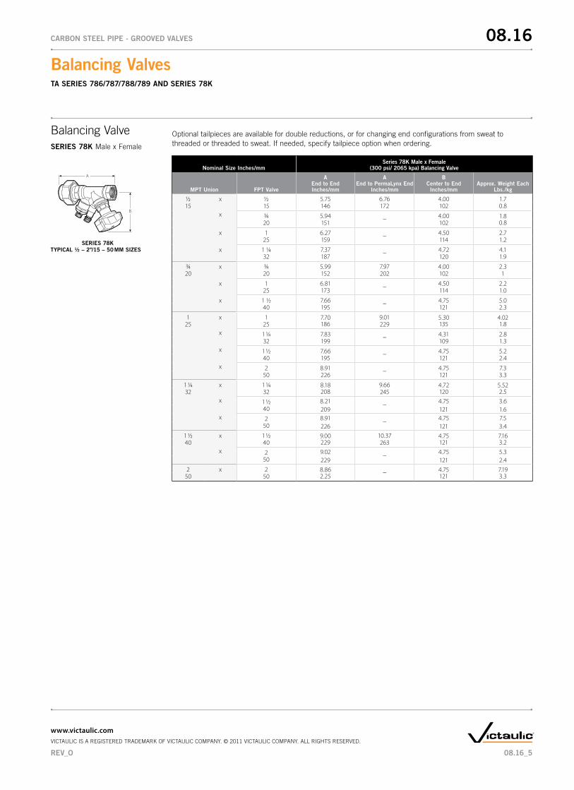
Balancing ValveSERIES 78K Male x Female
SERIES 78KTYPICAL ½ – 2"/15 – 50 MM SIZES
nominal Size Inches/mmSeries 78K Male x Female
(300 psi/ 2065 kpa) Balancing Valve
MPT Union FPT Valve
A End to EndInches/mm
A End to PermaLynx End
Inches/mm
B Center to End
Inches/mmApprox. Weight Each
Lbs./kg
1/2 x 1/2 5.75 6.76 4.00 1.715 15 146 172 102 0.8
x 3/4 5.94 – 4.00 1.80.820 151 102
x 1 6.27 – 4.50 2.725 159 114 1.2
x 1 1/4 7.37 – 4.72 4.132 187 120 1.9
3/4 x 3/4 5.99 7.97 4.00 2.320 20 152 202 102 1
x 1 6.81 – 4.50 2.225 173 114 1.0
x 1 1/2 7.66 – 4.75 5.040 195 121 2.3
1 x 1 7.70186
9.01 5.30135
4.021.825 25 229
x 1 1/4 7.83 – 4.31 2.832 199 109 1.3
x 1 1/2 7.66 – 4.75 5.240 195 121 2.4
x 2 8.91 – 4.75 7.350 226 121 3.3
1 1/4 x 1 1/4 8.18208
9.66 4.72120
5.522.532 32 245
x 1 1/2 8.21 – 4.75 3.640 209 121 1.6
x 2 8.91 – 4.75 7.550 226 121 3.4
1 1/2 x 1 1/2 9.00229
10.37 4.75121
7.163.240 40 263
x 2 9.02 – 4.75 5.350 229 121 2.4
2 x 2 8.862.25
– 4.75121
7.193.350 50
A
B
Optional tailpieces are available for double reductions, or for changing end configurations from sweat to threaded or threaded to sweat. If needed, specify tailpiece option when ordering.
08.16_5
Balancing Valves TA SERIES 786/787/788/789 And SERIES 78K
08.16CARBOn STEEL PIPE - GROOVEd VALVES
www.victaulic.comVICTAULIC IS A REGISTERED TRADEMARK OF VICTAULIC COMPANY. © 2011 VICTAULIC COMPANY. ALL RIGHTS RESERVED.
REV_O
Balancing ValveSERIES 78K Male x Female
SERIES 78KTYPICAL ½ – 2"/15 – 50 MM SIZES
A
B
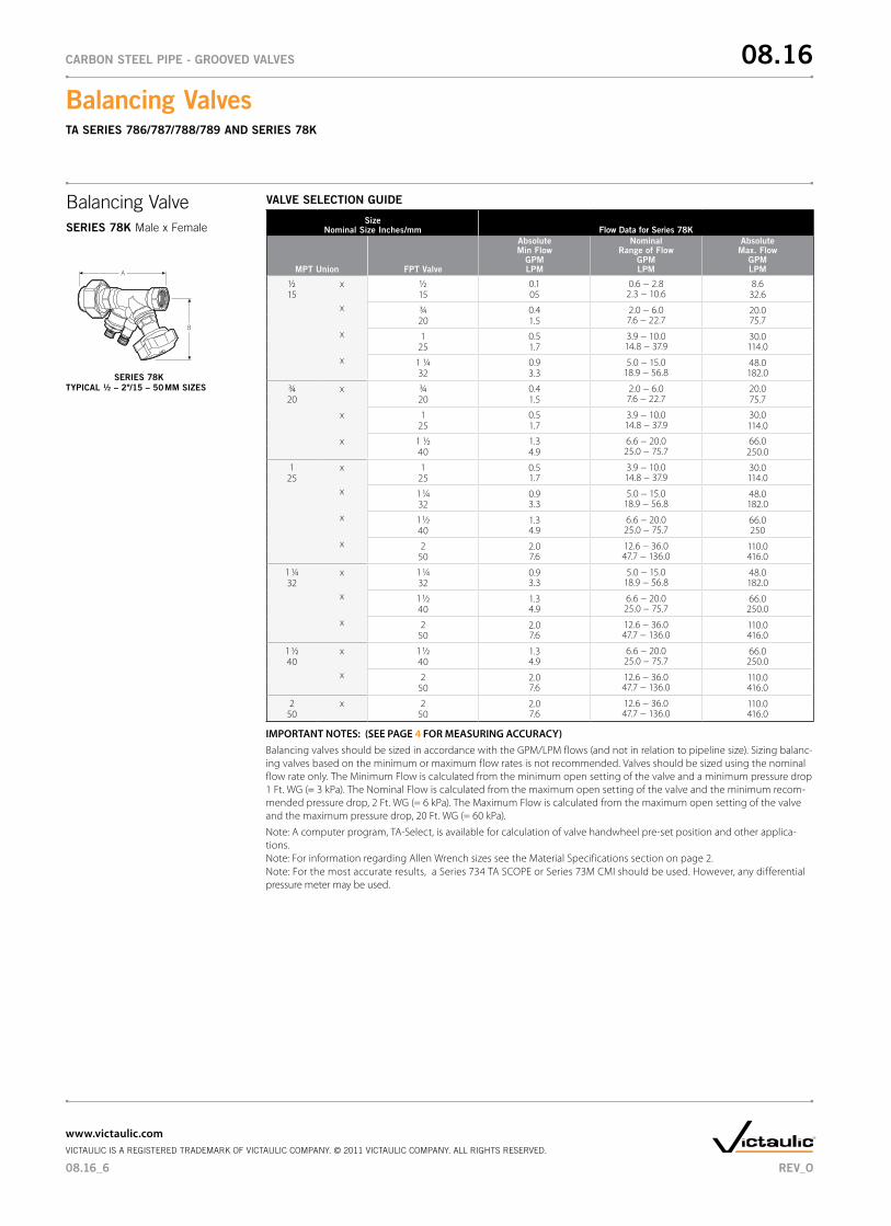
VALVE SELECTIOn GUIdE
Sizenominal Size Inches/mm Flow data for Series 78K
MPT Union FPT Valve
Absolute Min Flow
GPM LPM
nominal Range of Flow
GPMLPM
Absolute Max. Flow
GPM LPM
1/2 x 1/2 0.1 0.6 − 2.8 2.3 − 10.6
8.6 15 15 05 32.6
x 3/4 0.4 2.0 − 6.0 7.6 − 22.7
20.0 75.720 1.5
x 1 0.5 3.9 − 10.0 14.8 − 37.9
30.0 114.025 1.7
x 1 1/4 0.9 5.0 − 15.0 18.9 − 56.8
48.0 182.032 3.3
3/4 x 3/4 0.4 2.0 − 6.0 7.6 − 22.7
20.020 20 1.5 75.7
x 1 0.5 3.9 − 10.0 14.8 − 37.9
30.025 1.7 114.0
x 1 1/2 1.3 6.6 − 20.0 25.0 − 75.7
66.040 4.9 250.0
1 x 1 0.51.7
3.9 − 10.0 14.8 − 37.9
30.0 114.025 25
x 1 1/4 0.93.3
5.0 − 15.0 18.9 − 56.8
48.0 182.032
x 1 1/2 1.34.9
6.6 − 20.0 25.0 − 75.7
66.0 25040
x 2 2.0 7.6
12.6 − 36.0 47.7 − 136.0
110.0 416.050
1 1/4 x 1 1/4 0.93.3
5.0 − 15.0 18.9 − 56.8
48.0 182.032 32
x 1 1/2 1.34.9
6.6 − 20.0 25.0 − 75.7
66.0 250.040
x 2 2.0 7.6
12.6 − 36.0 47.7 − 136.0
110.0 416.050
1 1/2 x 1 1/2 1.34.9
6.6 − 20.0 25.0 − 75.7
66.0 250.040 40
x 2 2.07.6
12.6 − 36.0 47.7 − 136.0
110.0 416.050
2 x 2 2.0 7.6
12.6 − 36.0 47.7 − 136.0
110.0 416.050 50
IMPORTANT NOTES: (SEE PAGE 4 FOR MEASURING ACCURACY)Balancing valves should be sized in accordance with the GPM/LPM flows (and not in relation to pipeline size). Sizing balanc-ing valves based on the minimum or maximum flow rates is not recommended. Valves should be sized using the nominal flow rate only. The Minimum Flow is calculated from the minimum open setting of the valve and a minimum pressure drop 1 Ft. WG (= 3 kPa). The Nominal Flow is calculated from the maximum open setting of the valve and the minimum recom-mended pressure drop, 2 Ft. WG (= 6 kPa). The Maximum Flow is calculated from the maximum open setting of the valve and the maximum pressure drop, 20 Ft. WG (= 60 kPa).
Note: A computer program, TA-Select, is available for calculation of valve handwheel pre-set position and other applica-tions. Note: For information regarding Allen Wrench sizes see the Material Specifications section on page 2.Note: For the most accurate results, a Series 734 TA SCOPE or Series 73M CMI should be used. However, any differential pressure meter may be used.
08.16_6
Balancing Valves TA SERIES 786/787/788/789 And SERIES 78K
08.16CARBOn STEEL PIPE - GROOVEd VALVES
www.victaulic.comVICTAULIC IS A REGISTERED TRADEMARK OF VICTAULIC COMPANY. © 2011 VICTAULIC COMPANY. ALL RIGHTS RESERVED.
REV_O
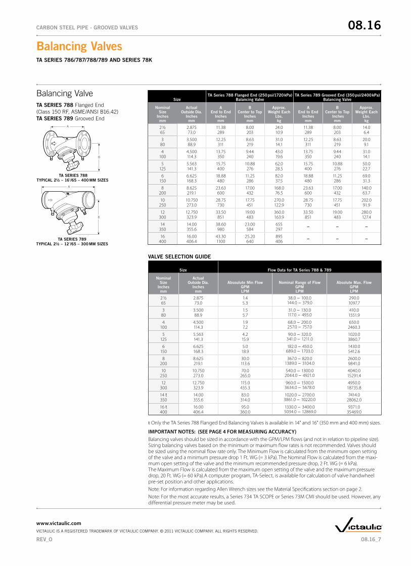
SizeTA Series 788 Flanged End (250 psi/1720 kPa)
Balancing ValveTA Series 789 Grooved End (350 psi/2400 kPa)
Balancing Valve
nominal Size
Inches mm
Actual Outside dia.
Inches mm
A End to End
Inches mm
B Center to Top
Inches mm
Approx. Weight Each
Lbs. kg
A End to End
Inches mm
B Center to Top
Inches mm
Approx. Weight Each
Lbs. kg
2 1/2 2.875 11.38 8.00 24.0 11.38 8.00 14.065 73.0 289 203 10.9 289 203 6.4
3 3.500 12.25 8.63 31.0 12.25 8.63 20.080 88.9 311 219 14.1 311 219 9.1
4 4.500 13.75 9.44 43.0 13.75 9.44 31.0100 114.3 350 240 19.6 350 240 14.1
5 5.563 15.75 10.88 62.0 15.75 10.88 50.0125 141.3 400 276 28.5 400 276 22.7
6 6.625 18.88 11.25 82.0 18.88 11.25 69.0150 168.3 480 286 37.5 480 286 31.3
8 8.625 23.63 17.00 168.0 23.63 17.00 140.0200 219.1 600 432 76.5 600 432 63.7
10 10.750 28.75 17.75 270.0 28.75 17.75 202.0250 273.0 730 451 122.9 730 451 91.9
12 12.750 33.50 19.00 360.0 33.50 19.00 280.0300 323.9 851 483 163.9 851 483 127.4
14 14.00 38.60 23.00 655350 355.6 980 584 297
– – –
16 16.00 43.30 25.20 895400 406.4 1100 640 406
– – –
Balancing ValveTA SERIES 788 Flanged End(Class 150 RF, ASME/ANSI B16.42) TA SERIES 789 Grooved End
A
B
TA SERIES 788TYPICAL 2½ – 16"/65 – 400 MM SIZES
A
B
TA SERIES 789TYPICAL 2½ – 12"/65 – 300 MM SIZES
ŧ Only the TA Series 788 Flanged End Balancing Valves is available in 14" and 16" (350 mm and 400 mm) sizes.
IMPORTANT NOTES: (SEE PAGE 4 FOR MEASURING ACCURACY)Balancing valves should be sized in accordance with the GPM/LPM flows (and not in relation to pipeline size). Sizing balancing valves based on the minimum or maximum flow rates is not recommended. Valves should be sized using the nominal flow rate only. The Minimum Flow is calculated from the minimum open setting of the valve and a minimum pressure drop 1 Ft. WG (= 3 kPa). The Nominal Flow is calculated from the maxi-mum open setting of the valve and the minimum recommended pressure drop, 2 Ft. WG (= 6 kPa). The Maximum Flow is calculated from the maximum open setting of the valve and the maximum pressure drop, 20 Ft. WG (= 60 kPa).A computer program, TA-Select, is available for calculation of valve handwheel pre-set position and other applications.Note: For information regarding Allen Wrench sizes see the Material Specifications section on page 2.Note: For the most accurate results, a Series 734 TA SCOPE or Series 73M CMI should be used. However, any differential pressure meter may be used.
Size Flow data for TA Series 788 & 789
nominal Size
Inches mm
Actual Outside dia.
Inches mm
Absoulute Min Flow GPM LPM
nominal Range of FlowGPM LPM
Absolute Max. Flow GPM LPM
2 1/2 2.875 1.4 38.0 − 100.0144.0 − 379.0
290.065 73.0 5.3 1097.7
3 3.500 1.5 31.0 − 130.0117.0 − 493.0
410.080 88.9 5.7 1551.9
4 4.500 1.9 68.0 − 200.0257.0 − 757.0
650.0100 114.3 7.2 2460.3
5 5.563 4.2 90.0 − 320.0341.0 − 1211.0
1020.0125 141.3 15.9 3860.7
6 6.625 5.0 182.0 − 450.0689.0 − 1703.0
1430.0150 168.3 18.9 5412.6
8 8.625 30.0 367.0 − 820.01389.0 − 3104.0
2600.0200 219.1 113.6 9841.0
10 10.750 70.0 540.0 − 1300.02044.0 − 4921.0
4040.0250 273.0 265.0 15291.4
12 12.750 115.0 960.0 − 1500.03634.0 − 5678.0
4950.0300 323.9 435.3 18735.8
14 ŧ 14.00 83.0 1020.0 − 2700.03861.0 − 10220.0
7414.0350 355.6 314.0 28062.0
16 ŧ 16.00 95.0 1330.0 − 3400.0 5034.0 − 12869.0
9371.0400 406.4 360.0 35469.0
VALVE SELECTIOn GUIdE
08.16_7
Balancing Valves TA SERIES 786/787/788/789 And SERIES 78K
08.16CARBOn STEEL PIPE - GROOVEd VALVES
www.victaulic.comVICTAULIC IS A REGISTERED TRADEMARK OF VICTAULIC COMPANY. © 2011 VICTAULIC COMPANY. ALL RIGHTS RESERVED.
REV_O
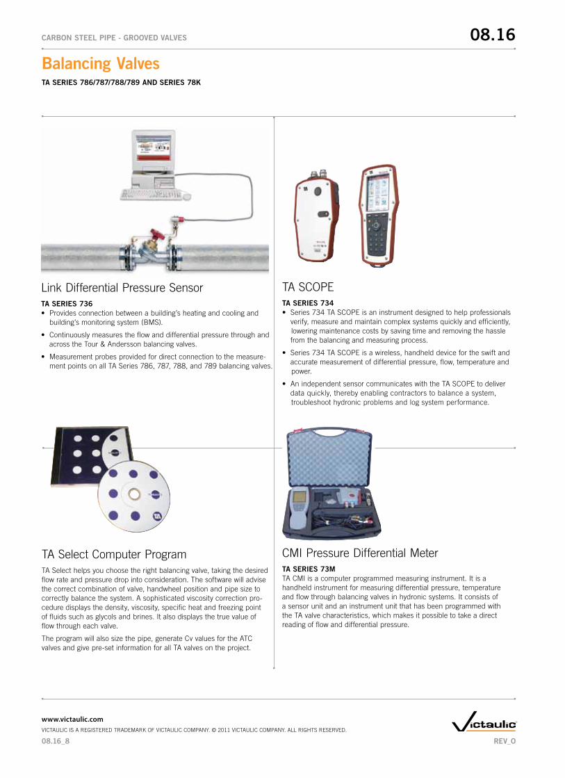
Link Differential Pressure SensorTA SERIES 736• Providesconnectionbetweenabuilding’sheatingandcoolingand
building’smonitoringsystem(BMS).
• Continuouslymeasurestheflowanddifferentialpressurethroughandacross the Tour & Andersson balancing valves.
• Measurementprobesprovidedfordirectconnectiontothemeasure-ment points on all TA Series 786, 787, 788, and 789 balancing valves.
TA SCOPETA SERIES 734• Series734TASCOPEisaninstrumentdesignedtohelpprofessionals verify, measure and maintain complex systems quickly and efficiently, lowering maintenance costs by saving time and removing the hassle from the balancing and measuring process.
• Series734TASCOPEisawireless,handhelddevicefortheswiftand accurate measurement of differential pressure, flow, temperature and power.
• AnindependentsensorcommunicateswiththeTASCOPEtodeliver data quickly, thereby enabling contractors to balance a system, troubleshoot hydronic problems and log system performance.
TA Select Computer ProgramTA Select helps you choose the right balancing valve, taking the desired flow rate and pressure drop into consideration. The software will advise the correct combination of valve, handwheel position and pipe size to correctly balance the system. A sophisticated viscosity correction pro-cedure displays the density, viscosity, specific heat and freezing point of fluids such as glycols and brines. It also displays the true value of flow through each valve.
The program will also size the pipe, generate Cv values for the ATC valves and give pre-set information for all TA valves on the project.
CMI Pressure Differential MeterTA SERIES 73MTA CMI is a computer programmed measuring instrument. It is a handheld instrument for measuring differential pressure, temperature and flow through balancing valves in hydronic systems. It consists of a sensor unit and an instrument unit that has been programmed with the TA valve characteristics, which makes it possible to take a direct reading of flow and differential pressure.
08.16_8
Balancing Valves TA SERIES 786/787/788/789 And SERIES 78K
08.16CARBOn STEEL PIPE - GROOVEd VALVES
www.victaulic.comVICTAULIC IS A REGISTERED TRADEMARK OF VICTAULIC COMPANY. © 2011 VICTAULIC COMPANY. ALL RIGHTS RESERVED.
REV_O
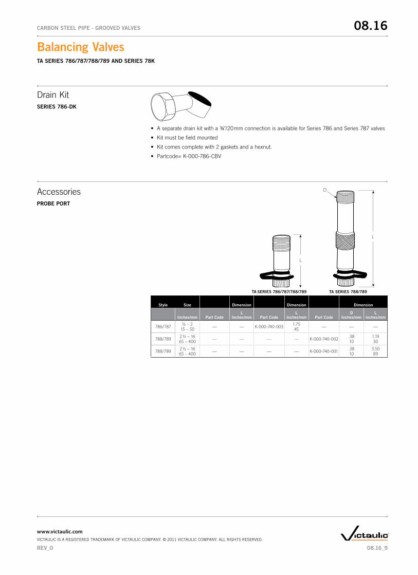
• Aseparatedrainkitwitha¾"/20 mm connection is available for Series 786 and Series 787 valves
• Kitmustbefieldmounted
• Kitcomescompletewith2gasketsandahexnut.
• Partcode=K-000-786-CBV
Drain KitSERIES 786-dK
AccessoriesPROBE PORT
L
SERIES 786/787/788/789 TA
L
D
SERIES 788/789
Style Size dimension dimension dimension
Inches/mm Part CodeL
Inches/mm Part CodeL
Inches/mm Part Coded
Inches/mmL
Inches/mm
786/787 1/2 – 2 — — K-000-740-003 1.75 — — —15 – 50 45
788/789 2 1/2 – 16 — — — — K-000-740-002 .38 1.1965 – 400 10 30
788/789 2 1/2 – 16 — — — — K-000-740-001 .38 3.5065 – 400 10 89
TA
08.16_9
Balancing Valves TA SERIES 786/787/788/789 And SERIES 78K
08.16CARBOn STEEL PIPE - GROOVEd VALVES
www.victaulic.comVICTAULIC IS A REGISTERED TRADEMARK OF VICTAULIC COMPANY. © 2011 VICTAULIC COMPANY. ALL RIGHTS RESERVED.
REV_O
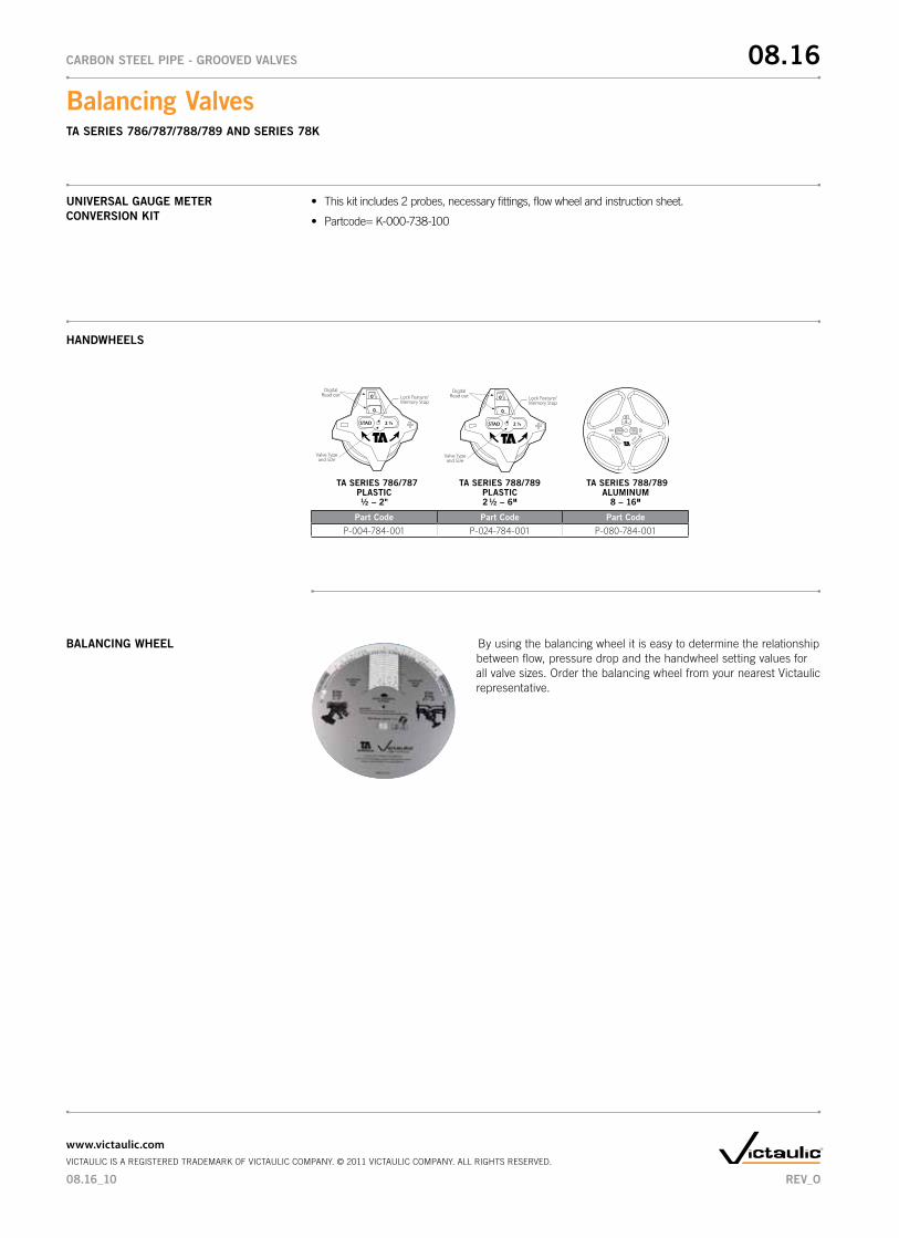
• Thiskitincludes2probes,necessaryfittings,flowwheelandinstructionsheet.
• Partcode=K-000-738-100
UnIVERSAL GAUGE METER COnVERSIOn KIT
HAndWHEELS
BALAnCInG WHEEL By using the balancing wheel it is easy to determine the relationship between flow, pressure drop and the handwheel setting v alues for all valve sizes. Order the balancing wheel from your nearest Victaulic representative.
0
0
STAD 2 ½
DigitalRead out
Valve Typeand Size
Lock Feature/Memory Stop
TA SERIES 786/787PLASTIC½ – 2"
TA SERIES 788/789PLASTIC2 ½ – 6"
TA SERIES 788/789ALUMInUM
8 – 16"
Part Code Part Code Part Code
P-004-784-001 P-024-784-001 P-080-784-001
0
0
STAD 2 ½
DigitalRead out
Valve Typeand Size
Lock Feature/Memory Stop
08.16_10
Balancing Valves TA SERIES 786/787/788/789 And SERIES 78K
08.16CARBOn STEEL PIPE - GROOVEd VALVES
www.victaulic.comVICTAULIC IS A REGISTERED TRADEMARK OF VICTAULIC COMPANY. © 2011 VICTAULIC COMPANY. ALL RIGHTS RESERVED.
REV_O
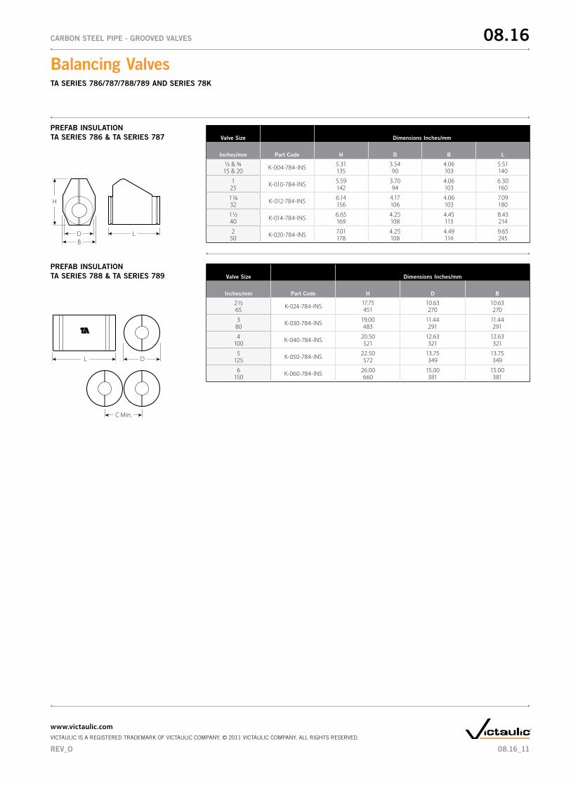
PREFAB InSULATIOnTA SERIES 786 & TA SERIES 787 Valve Size dimensions Inches/mm
Inches/mm Part Code H d B L
1/2 & 3/4 K-004-784-INS 5.31 3.54 4.06 5.5115 & 20 135 90 103 140
1 K-010-784-INS 5.59 3.70 4.06 6.3025 142 94 103 160
1 1/4 K-012-784-INS 6.14 4.17 4.06 7.0932 156 106 103 180
1 1/2 K-014-784-INS 6.65 4.25 4.45 8.4340 169 108 113 214
2 K-020-784-INS 7.01 4.25 4.49 9.6550 178 108 114 245
H
D LB
PREFAB InSULATIOnTA SERIES 788 & TA SERIES 789 Valve Size dimensions Inches/mm
Inches/mm Part Code H d B
2 1/2 K-024-784-INS 17.75 10.63 10.6365 451 270 270
3 K-030-784-INS 19.00 11.44 11.4480 483 291 291
4 K-040-784-INS 20.50 12.63 12.63100 521 321 321
5 K-050-784-INS 22.50 13.75 13.75125 572 349 349
6 K-060-784-INS 26.00 15.00 15.00150 660 381 381
L D
C Min.
08.16_11
Balancing Valves TA SERIES 786/787/788/789 And SERIES 78K
08.16CARBOn STEEL PIPE - GROOVEd VALVES
www.victaulic.comVICTAULIC IS A REGISTERED TRADEMARK OF VICTAULIC COMPANY. © 2011 VICTAULIC COMPANY. ALL RIGHTS RESERVED.
REV_O
TYPICAL SPECIFICATIOnS SERIES 78K – (½-2" M x F) TA SERIES 786 STAS – (½ – 2" SOLdER WITH dIGITAL HAndWHEEL)TA SERIES 787 STAd – (½ – 2" nPT)Furnish and install, as shown on the job plans, TA Series 786/787 Balancing Valves with provision for connecting a portable differential (Ft. of Head) pressure meter. Each meter shall have pressure/temperature probes.
The balancing valves shall be Y-pattern globe style design and all metal parts of nonferrous, pressure die cast, nonporous Ametal. Each valve shall provide four (4) functions:
(1) Precise flow measurement, (2) Precision flow balancing, (3) Positive shut-off with no drip seat, eliminatingtheneedofanadditionalisolationvalve,(4)Drainconnectionusing¾"NPThoseendthread.
These valves shall have four (4) 360° adjustment turns of the handwheel for precise setting with hidden memory to provide a tamper-proof balancing setting. Handwheel shall have digital readout. The handwheel can be installed in any position without affecting performance.
TA SERIES 788 STAF – (2 ½ – 12" FLAnGEd WITH dIGITAL HAnd WHEEL)TA SERIES 789 STAG – (2 ½ – 12" GROOVEd WITH dIGITAL HAnd WHEEL)Furnish and install, as shown on the job plans, TA Series 788/789 Balancing valves with provision for connecting a portable differential (Ft. of Head) pressure meter. Each meter connection shall have pressure/temperature probes.
The valancing valves shall be Y-pattern globe style design with ductile iron body all other wetted parts of nonferrous, pressure die cast Ametal. Each valve shall provide three (3) functions:
(1) Precision flow measurement, (2) Precision flow balancing, (3) Shut-off feature, eliminating the need of an additional isolation valve.
These valves shall have eight (8), twelve (12) or sixteen (16) 360° adjustment turns of the handwheel for precise setting with hidden memory feature to program the valve with precision tamper-proof balancing setting. Handwheel shall have digital readout. The handwheel can be installed in any position without affecting performance.
TA Balancing Valves ½" through 2": 300 psi/2065 kPa, y-pattern, globe type with soldered or threaded ends, non-ferrous Ametal® brass copper alloy body, EPDM o-ring seals. 4-turn digital readout handwheel for balancing, hidden memory feature with locking tamper-proof setting, and connections for portable differential meter. TA Series 786 STAS or 787 STAD.
TA Balancing Valves 2 ½" through 16": 300 psi/2065 kPa, y-pattern, globe type with flanged or grooved ends, ASTM A536 ductile iron body, all other metal parts of Ametal® brass copper alloy, EPDM O-ring seals. 8, 12, 16, 20 or 22 turn digital readout handwheel for balancing, hidden memory feature with locking tamper-proof setting, and connections for portable differential meter. TA Series 788 STAF or 789 STAG.
Purchased TA CBI-II or TA CMI balancing instruments are to be left with the project owner upon completion of the project.
Balancing Meter: If a balancing meter is required to be left with the owner after commissioning, the balancing meter shall be from the same provider as the balancing valves, Victaulic/Tour and Andersson. The Series 734 TA-Scope, or TA Series 73M CMI Pressure Differential Meter are acceptable and are manufactured by Tour and Andersson. Needle gauge type meters will not be allowed.
InSULATIOn:For insulation against heat loss or condensation. Preformed rigid polyurethane insulation is available for 1/2 – 2" TA Series 786/787 valves and for 2 1/2 – 6" TA Series 788/789 valves.
08.16_12
Balancing Valves TA SERIES 786/787/788/789 And SERIES 78K
08.16CARBOn STEEL PIPE - GROOVEd VALVES
www.victaulic.comVICTAULIC IS A REGISTERED TRADEMARK OF VICTAULIC COMPANY. © 2011 VICTAULIC COMPANY. ALL RIGHTS RESERVED.
REV_O
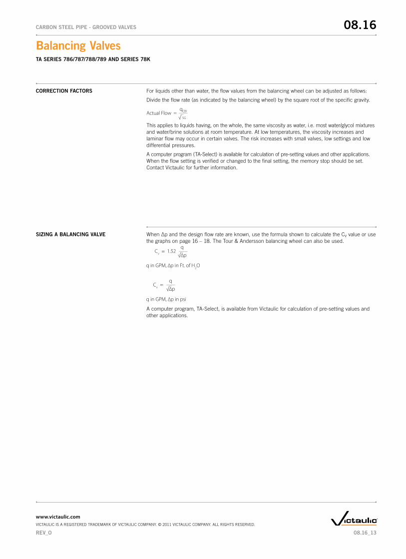
CORRECTIOn FACTORS For liquids other than water, the flow values from the balancing wheel can be adjusted as follows:
Divide the flow rate (as indicated by the balancing wheel) by the square root of the specific gravity.
qCBIActual Flow =SG
This applies to liquids having, on the whole, the same viscosity as water, i.e. most water/glycol mixtures and water/brine solutions at room temperature. At low temperatures, the viscosity increases and laminar flow may occur in certain valves. The risk increases with small valves, low settings and low differential pressures.
A computer program (TA-Select) is available for calculation of pre-setting values and other applications. When the flow setting is verified or changed to the final setting, the memory stop should be set. Contact Victaulic for further information.
SIZInG A BALAnCInG VALVE When ∆p and the design flow rate are known, use the formula shown to calculate the CV value or use the graphs on page 16 – 18. The Tour & Andersson balancing wheel can also be used.
A computer program, TA-Select, is available from Victaulic for calculation of pre-setting values and other applications.
08.16_13
Balancing Valves TA SERIES 786/787/788/789 And SERIES 78K
08.16CARBOn STEEL PIPE - GROOVEd VALVES
www.victaulic.comVICTAULIC IS A REGISTERED TRADEMARK OF VICTAULIC COMPANY. © 2011 VICTAULIC COMPANY. ALL RIGHTS RESERVED.
REV_O
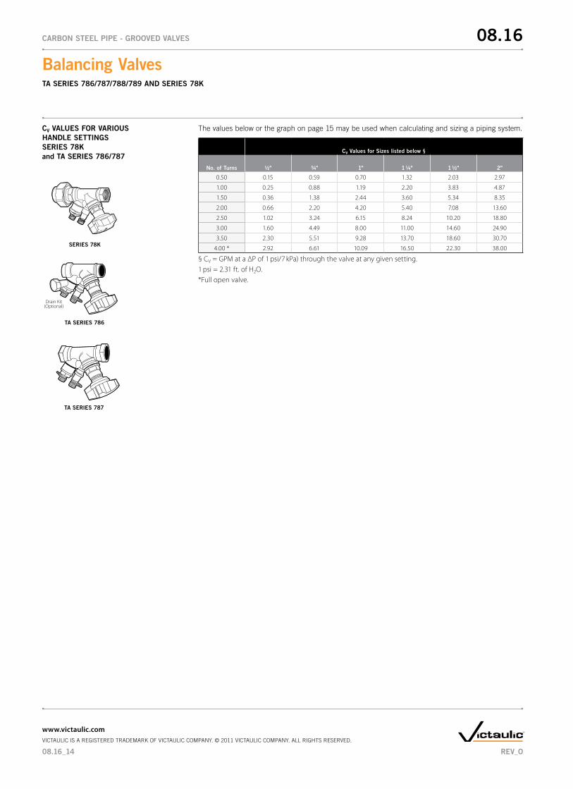
CV VALUES FOR VARIOUS HAndLE SETTInGSSERIES 78K and TA SERIES 786/787
The values below or the graph on page 15 may be used when calculating and sizing a piping system.
CV Values for Sizes listed below §
no. of Turns ½" 3/4" 1" 1 1/4" 1 ½" 2"
0.50 0.15 0.59 0.70 1.32 2.03 2.97
1.00 0.25 0.88 1.19 2.20 3.83 4.87
1.50 0.36 1.38 2.44 3.60 5.34 8.35
2.00 0.66 2.20 4.20 5.40 7.08 13.60
2.50 1.02 3.24 6.15 8.24 10.20 18.80
3.00 1.60 4.49 8.00 11.00 14.60 24.90
3.50 2.30 5.51 9.28 13.70 18.60 30.70
4.00 * 2.92 6.61 10.09 16.50 22.30 38.00
§ CV = GPM at a ΔP of 1 psi/7 kPa) through the valve at any given setting.1 psi = 2.31 ft. of H2O.*Full open valve.
Drain Kit(Optional)
TA SERIES 786
TA SERIES 787
SERIES 78K
08.16_14
Balancing Valves TA SERIES 786/787/788/789 And SERIES 78K
08.16CARBOn STEEL PIPE - GROOVEd VALVES
www.victaulic.comVICTAULIC IS A REGISTERED TRADEMARK OF VICTAULIC COMPANY. © 2011 VICTAULIC COMPANY. ALL RIGHTS RESERVED.
REV_O
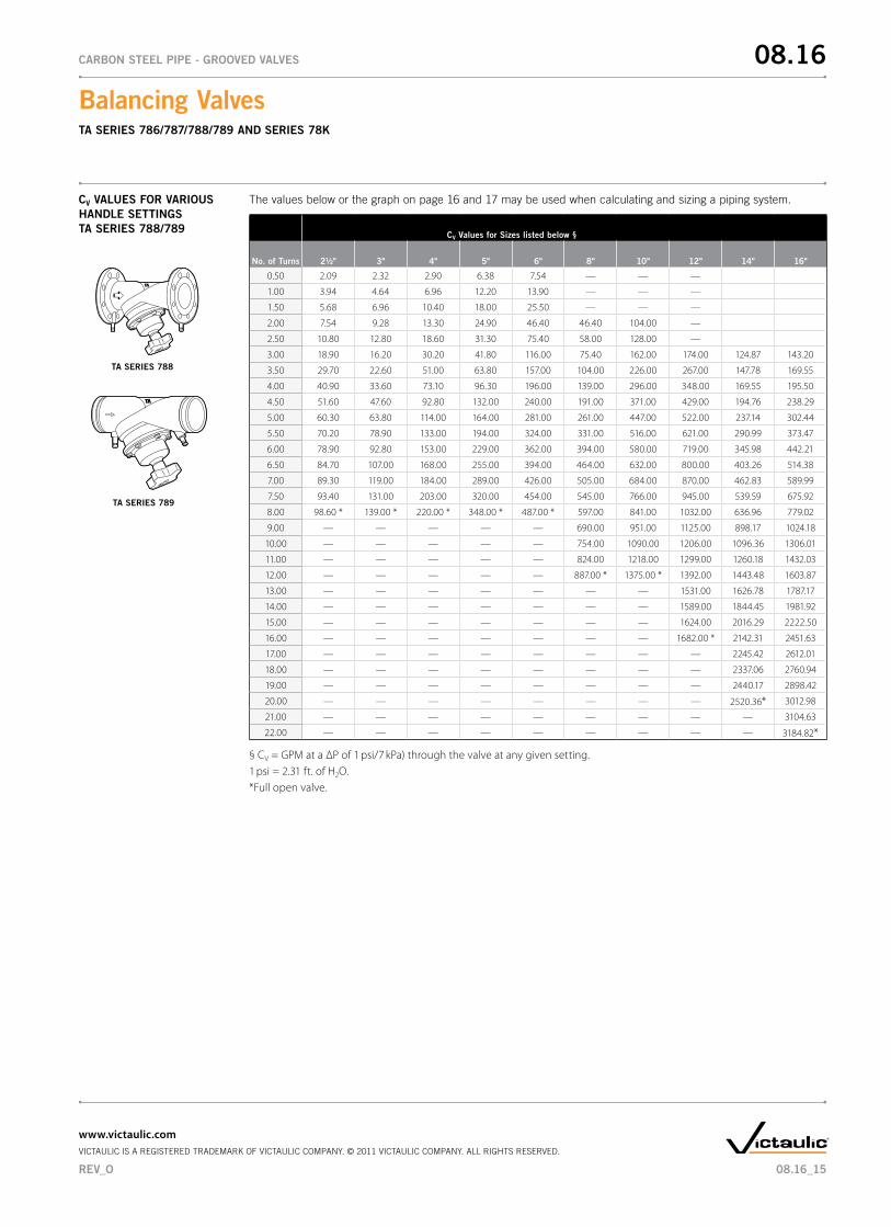
CV VALUES FOR VARIOUS HAndLE SETTInGSTA SERIES 788/789
The values below or the graph on page 16 and 17 may be used when calculating and sizing a piping system.
CV Values for Sizes listed below §
no. of Turns 2½" 3" 4" 5" 6" 8" 10" 12" 14" 16"
0.50 2.09 2.32 2.90 6.38 7.54 — — — — —
1.00 3.94 4.64 6.96 12.20 13.90 — — — — —
1.50 5.68 6.96 10.40 18.00 25.50 — — — — —
2.00 7.54 9.28 13.30 24.90 46.40 46.40 104.00 — — —
2.50 10.80 12.80 18.60 31.30 75.40 58.00 128.00 — — —
3.00 18.90 16.20 30.20 41.80 116.00 75.40 162.00 174.00 124.87 143.20
3.50 29.70 22.60 51.00 63.80 157.00 104.00 226.00 267.00 147.78 169.55
4.00 40.90 33.60 73.10 96.30 196.00 139.00 296.00 348.00 169.55 195.50
4.50 51.60 47.60 92.80 132.00 240.00 191.00 371.00 429.00 194.76 238.29
5.00 60.30 63.80 114.00 164.00 281.00 261.00 447.00 522.00 237.14 302.44
5.50 70.20 78.90 133.00 194.00 324.00 331.00 516.00 621.00 290.99 373.47
6.00 78.90 92.80 153.00 229.00 362.00 394.00 580.00 719.00 345.98 442.21
6.50 84.70 107.00 168.00 255.00 394.00 464.00 632.00 800.00 403.26 514.38
7.00 89.30 119.00 184.00 289.00 426.00 505.00 684.00 870.00 462.83 589.99
7.50 93.40 131.00 203.00 320.00 454.00 545.00 766.00 945.00 539.59 675.92
8.00 98.60 * 139.00 * 220.00 * 348.00 * 487.00 * 597.00 841.00 1032.00 636.96 779.02
9.00 — — — — — 690.00 951.00 1125.00 898.17 1024.18
10.00 — — — — — 754.00 1090.00 1206.00 1096.36 1306.01
11.00 — — — — — 824.00 1218.00 1299.00 1260.18 1432.03
12.00 — — — — — 887.00 * 1375.00 * 1392.00 1443.48 1603.87
13.00 — — — — — — — 1531.00 1626.78 1787.17
14.00 — — — — — — — 1589.00 1844.45 1981.92
15.00 — — — — — — — 1624.00 2016.29 2222.50
16.00 — — — — — — — 1682.00 * 2142.31 2451.63
17.00 — — — — — — — — 2245.42 2612.01
18.00 — — — — — — — — 2337.06 2760.94
19.00 — — — — — — — — 2440.17 2898.42
20.00 — — — — — — — — 2520.36* 3012.98
21.00 — — — — — — — — — 3104.63
22.00 — — — — — — — — — 3184.82*
§ CV = GPM at a ΔP of 1 psi/7 kPa) through the valve at any given setting.1 psi = 2.31 ft. of H2O.*Full open valve.
TA SERIES 788
TA SERIES 789
08.16_15
Balancing Valves TA SERIES 786/787/788/789 And SERIES 78K
08.16CARBOn STEEL PIPE - GROOVEd VALVES
www.victaulic.comVICTAULIC IS A REGISTERED TRADEMARK OF VICTAULIC COMPANY. © 2011 VICTAULIC COMPANY. ALL RIGHTS RESERVED.
REV_O
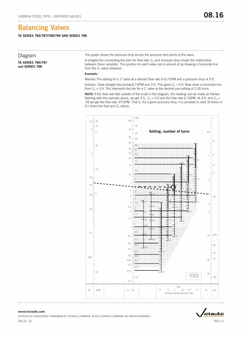
DiagramTA SERIES 786/787 and SERIES 78K
This graph shows the pressure drop across the pressure test points of the valve.
A straight line connecting the bars for flow rate, CV and pressure drop shows the relationship between these variables. The position for each valve size is arrived at by drawing a horizontal line from the CV value obtained.
Example:
Wanted: Pre-setting for a 1" valve at a desired flow rate of 6.7 GPM and a pressure drop of 3 ft.
Solution: Draw straight line joining 6.7 GPM and 3 ft. This gives CV=5.9.Nowdrawahorizontallinefrom CV=5.9.Thisintersectsthebarfora1"valveatthedesiredpre-settingof2.35turns.
NOTE: If the flow rate falls outside of the scale in the diagram, the reading can be made as follows: Starting with the example above, we get 3 ft., CV=5.9andtheflowrate6.7GPM.At3ft.andCV=.59 we get the flow rate .67 GPM. That is, for a given pressure drop, it is possible to read 10 times or 0.1 times the flow and CV values.
2
1
0.5
0.4
0.3
0.2
0.1
0.05
2.5 40
3.5
3
20
10
5
2
1
0.5
l/s GPM ft. kPaCv Kv 1½" 2"1" 1¼"½" ¾"Size
TA Series 786/787 and Series 78K
5
4
3
2
1
30
20
10
0.5
1
2
3
4
5
10
30*)
40
50
100
**)
4
3
2.5
0.751
0.5
0.4
0.35
0.3
0.25 2
1.5
1
0.5
4
3
2.5
2
1.5
1
0.5
4
3
2.5
2
1.5
1
0.5
4
3
2.5
2
1.5
1
0.5
4
3
2.5
2
1.5
1
0.5
4
3
2
1.5
1
0.5
0.1
0.15
0.2
0.25
0.3
0.4
0.5
0.7
1
1.5
2
2.5
3
4
5
7
10
15
20
25
30
40
50
70
100
Setting, number of turns
0.1
0.15
0.2
0.25
0.3
0.4
0.5
0.7
1
1.5
2
2.5
3
4
5
7
10
15
20
25
30
40
50
70
100
0.751
0.5
0.4
0.35
0.3
0.25
2.5
*25 db (A)**35 db (A)
08.16_16
Balancing Valves TA SERIES 786/787/788/789 And SERIES 78K
08.16CARBOn STEEL PIPE - GROOVEd VALVES
www.victaulic.comVICTAULIC IS A REGISTERED TRADEMARK OF VICTAULIC COMPANY. © 2011 VICTAULIC COMPANY. ALL RIGHTS RESERVED.
REV_O
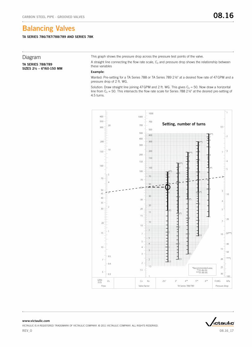
DiagramTA SERIES 788/789SIZES 2½ – 6"/60-150 MM
This graph shows the pressure drop across the pressure test points of the valve.
A straight line connecting the flow rate scale, CV and pressure drop shows the relationship between these variables
Example:
Wanted: Pre-setting for a TA Series 788 or TA Series 789 2 1/2" at a desired flow rate of 47 GPM and a pressure drop of 2 ft. WG.
Solution: Draw straight line joining 47 GPM and 2 ft. WG. This gives CV=50.Nowdrawahorizontalline from CV=50.ThisintersectstheflowratescaleforSeries78821/2"atthedesiredpre-settingof4.5 turns.
1
1.5
2
3
4
5
7
10
15
20
30
50
70
100
150
200
300
400
500
20
10
5
4
3
2
1
0.5
0.4
0.3
5045
40
35
30
20
10
15
7
400
350
300
200
100
150
70
5
l/sGPM(US) Ft.WG kPaKvCv
Flow Valve factor TA Series 788/789 Pressure drop
2½" 3" 4"* 5"* 6"*
700
1000
1.5
2
3
4
5
7
10
15
20
30
50
70
100
150
200
300
400
500
700
1000
30
25
20
15
10
7
5
4
3
2
1
0.5
1
2
3
4
5
4
5
678**)
3*)
2
1
0.5
20
10
30***)
40
50
100
****)
4
5
6
7
8**)
3*)
2
1
0.5
4
5
6
7
8**)
3*)
2
1
0.5
4
5
6
78**)
3*)
2
1
0.5
4
5
678**)
3*)
2
1
Setting, number of turns
*Recommended area **25 db (A)***35 db (A)
08.16_17
Balancing Valves TA SERIES 786/787/788/789 And SERIES 78K
08.16CARBOn STEEL PIPE - GROOVEd VALVES
www.victaulic.comVICTAULIC IS A REGISTERED TRADEMARK OF VICTAULIC COMPANY. © 2011 VICTAULIC COMPANY. ALL RIGHTS RESERVED.
REV_O
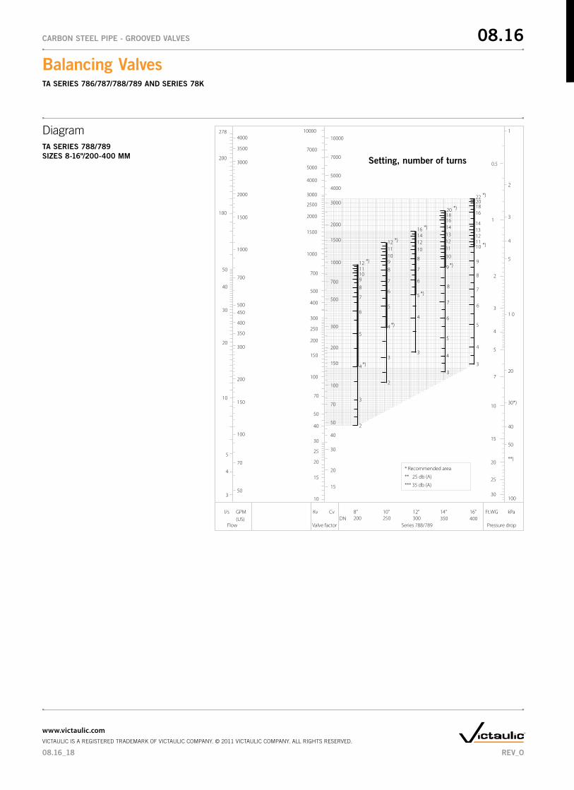
DiagramTA SERIES 788/789SIZES 8-16"/200-400 MM
* Recommended area
** 25 db (A)
*** 35 db (A)50
3000
2000
1500
1000
700
500450
400
350
300
200
150
100
70
GPM(US)
4000
3500
200
100
50
40
30
20
10
5
4
3
278
l/s
10000
7000
5000
4000
40
30
20
15
Cv
10
15
20
25
30
40
50
70
100
150
200
250
300
400
500
700
1000
1500
2000
2500
3000
4000
5000
Kv
7000
10000
0.5
Ft.WG kPa
1
2
3
4
5
20
1 0
30*)
40
50
100
**)
40016”
35014”
30012”
25010”
2008”
DN
3000
2000
1500
1000
700
500
300
200
150
100
70
50
1
2
3
4
5
7
10
20
30
15
25
4 *)
3
6
5
7
8
9101112 *)
2
4 *)
3
6
5
7
8
9101112 *)
2
4
3
6
5
7
8
10 *)
12
14
16
9
11
13
2022 *)
6
5
8
7
9 *)
10
111213
16
3
4
14
20 *)18
4
3
6
5 *)
7
8
10121416 *)
18
Setting, number of turns
Flow Valve factor Series 788/789 Pressure drop
08.16_18
Balancing Valves TA SERIES 786/787/788/789 And SERIES 78K
08.16CARBOn STEEL PIPE - GROOVEd VALVES
www.victaulic.comVICTAULIC IS A REGISTERED TRADEMARK OF VICTAULIC COMPANY. © 2011 VICTAULIC COMPANY. ALL RIGHTS RESERVED.
REV_O
WARRAnTY Refer to the Warranty section of the current Price List or contact Victaulic for details.
This product shall be manufactured by Victaulic or to Victaulic specifications. All products to be installed in accordance with current Victaulic installation/assembly instructions as recommended by Tour and Andersson. Victaulic reserves the right to change product specifications, designs and standard equipment without notice and without incurring obligations.
nOTE
08.16
Balancing Valves TA SERIES 786/787/788/789 And SERIES 78K
08.16CARBOn STEEL PIPE - GROOVEd VALVES
For complete contact information, visit www.victaulic.com08.16 0930 REV O UPDATED 2/2011VICTAULIC IS A REGISTERED TRADEMARK OF VICTAULIC COMPANY. © 2011 VICTAULIC COMPANY. ALL RIGHTS RESERVED.


