fibrous glass duct liner standard - insulation … · fibrous glass duct liner standard 5 section...
TRANSCRIPT

FIBROUSGLASS
DUCT LINERSTANDARD
DESIGN,FABRICATION AND
INSTALLATIONGUIDELINES
THIRD EDITION, 2002
COPYRIGHT R 2002, NAIMA, ALL RIGHTS RESERVED $7.50
NAIMANorth American Insulation
Manufacturers Association

PREFACE
The North American Insulation Manufacturers Association(NAIMA) presents this Standard as a recommendedguideline for the selection, fabrication and installation offibrous glass duct liner insulations in sheet metal airhandling ducts as defined herein. Fibrous glass duct linerinsulations are designed for use in air duct systemsoperating at air velocities not exceeding 6,000 feet perminute (30.5 m/s), or not to exceed rated air velocities forproduct types as listed by their manufacturers.
This voluntary standard has been prepared to meet the needfor detailed information regarding materials, specification,fabrication, and installation of fibrous glass liners.Additionally, brief recommendations are offered regardingthe commissioning, operation, and maintenance of fibrousglass lined duct systems so that they may more dependablyprovide desired acoustical, thermal, and indoor aircomfort performance for the system’s design service life.
This Standard is intended to expand references to fibrousglass materials and installation methods in HVAC DuctConstruction Standards - Metal and Flexible, first edition,1985, seventh printing (1989), published by the Sheet Metaland Air Conditioning Contractors National Association(SMACNA), in particular, pages 2-25 through 2-31.
This Standard was developed using reliable engineeringprinciples and research, plus consultation with andinformation obtained from manufacturers, contractors,testing laboratories, and others having specializedexperience. It is subject to revision as further experienceand investigation may show is necessary or desirable.Constructions and products which comply with thisStandard will not necessarily be considered acceptableif, when examined and tested, they are found to haveother features which impair the result contemplated bythis Standard.
The North American Insulation Manufacturers Associationassumes no responsibility and accepts no liability for theapplication of the principles or techniques contained in thismanual. In particular, NAIMA makes no warranty of anykind, express or implied, regarding merchantability orfitness for any particular purpose, in connection withthe information supplied herein. Authorities consideringadoption of this Standard should review all Federal, State,local, and contractual regulations applicable to specificinstallations.
This Standard is not intended to preclude alternate methodsand materials of fabrication when such methods andmaterials can be documented as providing equivalentperformance.
This Standard is not intended to address issues relatingto thermal or acoustical insulation within and furnished asintegral parts of HVAC equipment such as air handlingunits, coils, air cleaners, silencers, humidifiers, andterminal devices. Manufacturers of such equipment areresponsible for design, specification, and installation ofappropriate insulation components in their products sothat thermal, acoustical, and indoor air qualityrequirements are met.
The North American Insulation Manufacturers Associationextends its thanks to the member companies of its AirHandling Technical Subcommittee who contributed theirtime and talents in the development of this Standard.
NAIMA Air Handling Member Companies:
CertainTeed Corp.P. O. Box 860, Valley Forge, PA 19482800-233-8990
Johns ManvilleP. O. Box 5108, Denver, CO 80217800-654-3103
Knauf Insulation1 Knauf Drive, Shelbyville, IN 46176800-825-4434
Owens CorningOne Owens Corning Parkway,Toledo, OH 43659800-GET-PINK
FIBROUS GLASS DUCT LINER STANDARD
1
CONTENTS
Preface .............................................................................................................................................................................. 1Contents ............................................................................................................................................................................ 2References .................................................................................................................................................................... 3, 4
SECTION I. DESIGN CRITERIABackground, Benefits ....................................................................................................................................................... 5Properties of Materials per ASTM C 1071 ........................................................................................................................ 5Properties of Duct Liner Adhesives and Fasteners .......................................................................................................... 6System Acoustical Performance ....................................................................................................................................... 7Definitions ......................................................................................................................................................................... 7System Thermal Performance, ASHRAE/IES 90.1-1989 .................................................................................................. 8System Thermal Performance, ANSI/ASHRAE/IESNA 90.1-2001 .............................................................................. 9, 10System Thermal Performance, ASHRAE 90.2-2001 ....................................................................................................... 11Indoor Environmental Quality and Duct Insulation ......................................................................................................... 12Fire Safety Considerations .............................................................................................................................................. 12Condensation Control Performance ............................................................................................................................... 13Design Considerations ................................................................................................................................................... 14Short Form Specification................................................................................................................................................. 15CSI 3-Part Specification ............................................................................................................................................ 16, 17
SECTION II. FABRICATION STANDARDSApplication Considerations ............................................................................................................................................. 18Cutting Fibrous Glass Duct Liner .................................................................................................................................... 18Duct Liner Adhesives ...................................................................................................................................................... 18Mechanical Fastening ..................................................................................................................................................... 19General Fabrication and Installation Principles .............................................................................................................. 20Duct Liner Corner Treatments ......................................................................................................................................... 21Duct Liner Nosing Treatments ........................................................................................................................................ 21Build-out for Installing Turning Vanes and Accessories ................................................................................................. 22Interruption of Duct Liner at Fire Dampers ..................................................................................................................... 23
SECTION III. SYSTEM OPERATIONInstalling and commissioning lined duct systems .......................................................................................................... 24Operation and preventive maintenance of ducts ........................................................................................................... 24Cleaning of lined duct systems ................................................................................................................................ 25, 26
INSPECTION CHECK LIST FOR FIBROUS GLASS DUCT LINER INSTALLATION .................................... 27FACTS ON FIBROUS GLASS DUCT INSULATION ..................................................................................... 28, 29
2
FIBROUS GLASS DUCT LINER STANDARDNAIMANorth American Insulation
Manufacturers Association

FIBROUS GLASS DUCT LINER STANDARD
3
REFERENCES
The following may be used as references when workingwith information in this Standard. NOTE: Current editions ofsome references may differ from editions of listed date.
ASHRAE - American Society of Heating,Refrigerating, and Air-Conditioning Engineers, Inc.
1791 Tullie Circle, N.E., Atlanta, GA 30329-2305• 1999 ASHRAE Handbook - Heating, Ventilating, and
Air-Conditioning Applications• 2000 ASHRAE Handbook - Heating, Ventilating, and
Air-Conditioning Systems and Equipment• 2001 ASHRAE Handbook - Fundamentals• ANSI/ASHRAE Standard 52.2-1999, Method of Testing
General Ventilation Air-Cleaning Devices for RemovalEfficiency by Particle Size
• ANSI/ASHRAE Standard 62-2001, Ventilation forAcceptable Indoor Air Quality
• ASHRAE/IES 90.1-1989, Energy Efficient Design of NewBuildings Except Low Rise Residential Buildings
• ANSI/ASHRAE/IESNA Standard 90.1-2001, EnergyStandard for Buildings Except Low Rise ResidentialBuildings
• ASHRAE 90.2-2001, Energy Efficient Design of New LowRise Residential Buildings
• A Practical Guide to Noise and Vibration Control for HVACSystems: Mark E. Schaffer
• ASHRAE Humidity Control Design Guide For Commercialand Institutional Buildings, ISBN 1-B83413-98-2
ASTM - American Society for Testing and Materials
100 Barr Harbor Drive, West Conshohocken, PA19428-2959• ASTM C 167 - Test Methods for Thickness and Density
of Blanket or Batt Thermal Insulation• ASTM C 177 - Test Method for Steady-State Heat Flux
Measurement and Thermal Transmission Properties byMeans of the Guarded-Hot-Plate Apparatus
• ASTM C 390 - Criteria for Sampling and Acceptance ofPreformed Thermal Lots
• ASTM C 411 - Test Method for Hot-Surface Performanceof High-Temperature Thermal Insulation
• ASTM C 423 - Test Method for Sound Absorption andSound Absorption Coefficients by the ReverberationRoom Method
• ASTM C 518 - Test Method for Steady-State Heat FluxMeasurements and Thermal Transmission Properties byMeans of the Heat Flow Meter Apparatus
• ASTM C 665 - Specification for Mineral-Fiber BlanketThermal Insulation for Light Frame Construction andManufactured Housing
• ASTM C 916 - Standard Specification for Adhesives forDuct Liner Insulation
• ASTM C 1104/C - 1104M Test Method for Determining theWater Vapor Sorption of Unfaced Mineral Fiber Insulation
• ASTM C 1071 - Standard Specification for Duct LiningInsulation (Thermal and Sound Absorbing Material)
• ASTM C 1338 - Test Method for Determining FungiResistance of Insulation Materials and Facings
• ASTM E 84 - Test Method for Surface BurningCharacteristics of Building Materials
• ASTM E 795 - Practices for Mounting Test SpecimensDuring Sound Absorption Tests
• ASTM G 21-96 - Practice for Determining Resistanceof Synthetic Polymer Materials to Fungi
• ASTM G 22-96 - Practice for Determining Resistanceof Plastics to Bacteria
EPA - Environmental Protection Agency
1200 Pennsylvania Ave., Washington, DC 20460• Building Air Quality: A Guide for Facility Owners and
Building Managers
NAIMA - North American Insulation ManufacturersAssociation
44 Canal Center Plaza, Suite 310, Alexandria, VA 22314• Pub. # AH-106, Benefits and Recommended Use of
Fibrous Glass Duct Liners• Pub. # AH-110, Fiber Glass HVAC Insulations: An
Essential Component of Indoor IEQ• Pub. # AH-113, The Facts About Mold Growth• Pub. # AH-114, The Facts About Airborne Fibers• Pub. # AH-122, Cleaning Fibrous Glass Insulated Air Duct
Systems, Recommended Practice• Pub. # AH-125, Facts About the Use of Biocides and
Encapsulants with Fiber Glass Air Duct Insulations
NFPA - National Fire Protection Association
1 Batterymarch Park, P.O. Box 9101, Quincy, MA 02269• NFPA 90A - Standard for the Installation of
Air-Conditioning and Ventilating Systems, 1999 Edition• NFPA 90B - Standard for the Installation of Warm Air
Heating and Air Conditioning Systems, 1999 Edition
NAIMANorth American Insulation
Manufacturers Association

4
FIBROUS GLASS DUCT LINER STANDARD
• NFPA 255 - Standard Method of Test of Surface BurningCharacteristics of Building Materials
• NFPA 259 – Standard Test Method for Potential Heat ofBuilding Materials, 1993 Edition
SMACNA - Sheet Metal and Air ConditioningContractors National Association
P.O. Box 221230, Chantilly, VA 22022-1230• HVAC Duct Construction Standards - Metal and Flexible,
Second Edition, 1995• HVAC Systems Duct Design, Third Edition, 1990• Ducted Electric Heater Guide for Air Handling Systems,
Second Edition, 1994• Fire, Smoke & Radiation Damper Guide for HVAC
Systems, Fourth Edition, 1992• HVAC Systems Applications, First Edition, 1987• Indoor Air Quality Manual, Second Edition, 1993
ICC - International Code Council, Inc.
900 Montclair Road, Birmingham, AL 35213-1206
The following International codes replace BOCA and CABOcodes as noted:• International Mechanical Code, 2000• International Building Code, 2000• International Residential Code, 2000• International Energy Conservation Code, 2000
• BOCA - Building Officials and Code AdministratorsInternational, Inc.4051 North Flossmoor Road, Country Club Hills, IL60478-5795
• BOCA National Building Code, 1996 Edition• BOCA National Mechanical Code, 1996 Edition
(Replaced by ICC; see above)
• CABO - Council of American Building Officials5203 Leesburg Pike, Suite 708, Falls Church, VA 22041
• CABO One and Two Family Dwelling Code, 1995 Edition(Replaced by ICC; see above)
• CABO Model Energy Code, 1995 Edition. 1997Amendments (Replaced by ICC; see above), 1995Edition (Replaced by ICC; see above)
• ICBO - International Conference of Building Officials5360 Workman Mill Road, Whittier, CA 90601
• Uniform Building Code, 1997 Edition• Uniform Mechanical Code, 1997 Edition
• SBCCI - Southern Building Code Congress International900 Montclair Road, Birmingham, AL 35213-1206
• Standard Building Code, 1997 Edition• Standard Mechanical Code, 1997 Edition
Refer to area codes and municipal ordinances for additionalspecific local requirements for ducted heating and airconditioning systems.
ADDITIONAL REFERENCES
AIA - American Institute of Architects
• Guidelines for Design and Construction of Hospital andHealth Care Facilities (ISBN I-57165-002-4), 2001.
AMA - American Medical Association
• Archives of Environmental Health, February 1971,Volume 22: Erosion of Fibers From Installed Fibrous-GlassDucts: Jacob Cholak, ChE, and Lawrence J. Schafer,BSE(ChE), Cincinnati
AIHA - American Industrial Hygiene Association
• American Industrial Hygiene Association Journal,August 1971, Volume 32, Number 8: Fibrous Glass-Lined Air Transmission Systems: An Assessment ofTheir Environmental Effects. J. LeRoy Balzer,W. Clark Cooper, M.D., and Douglas P. Fowler,Environmental Health Sciences, School of Public Health,University of California, Berkeley, California 94720
For product design and performance reference data, referto manufacturers’ catalogs and/or data sheets.
NAIMANorth American Insulation
Manufacturers Association

FIBROUS GLASS DUCT LINER STANDARD
5
SECTION I. DESIGN CRITERIA
A. BACKGROUND
Introduction of forced air heating, ventilating, and airconditioning systems established the need for ductinsulation. A forced air duct system is designed to be aconduit for supply and return of conditioned air to andfrom occupied spaces of a building. It is insulated tocontrol duct-borne noise, to reduce heat loss or gainthrough metal duct walls, and to minimize water vaporcondensation. An internally lined duct system conveysconditioned air quietly to occupied spaces at designtemperature and humidity.
B. BENEFITS
A sealed sheet metal duct system with fibrous glass ductliner provides outstanding performance in these ways:• Fibrous glass duct liners attenuate the noises generated
by HVAC equipment, air velocity, and occupant cross-talk.• Fibrous glass duct liners reduce heat loss or gain
through sheet metal duct surfaces.• Fibrous glass duct liner thermal performance, in
combination with sealed sheet metal duct surfacesacting as an air and vapor retarder, helps to preventthe formation of water vapor condensation inside theduct as well as on its outside surface.
• Exterior surfaces of metal duct systems with fibrousglass liners protect the insulation from abuse.
• Fibrous glass duct liners may be fabricated along withthe sheet metal ductwork in the shop, allowing forquality workmanship under controlled conditions.
C. PROPERTIES OF MATERIALS
1. FIBROUS GLASS DUCT LINERS
TYPES: TYPES: TYPES: TYPES: TYPES: Fibrous glass duct liners are manufactured ofglass fibers bonded with thermosetting resin. They aredimensionally stable, withstand abuse, and provide acleanable fire-resistant interior surface designed tominimize friction loss. This interior treatment may be inthe form of a coating and/or a mat facing. Two forms areavailable: (1) flexible blankets supplied in rolls; (2) rigidboards supplied in sheet form.
PROPERPROPERPROPERPROPERPROPERTIES:TIES:TIES:TIES:TIES: Fibrous glass duct liners are designedto meet physical property requirements of ASTM C 1071,Standard Specification for Thermal and AcousticalInsulation (Glass Fiber, Duct Lining Material). Thisspecification defines the two types of duct liner describedabove: Type I - Flat, in roll form; Type II - Flat, in sheet form.
Acoustical performance: When tested in accordance withASTM C 423 (Mounting A), duct liner insulation shall havesound absorption coefficients not less than those in thetable below:
Sound absorption coef Sound absorption coef Sound absorption coef Sound absorption coef Sound absorption coefficients atficients atficients atficients atficients atThicknessThicknessThicknessThicknessThickness octave band center fr octave band center fr octave band center fr octave band center fr octave band center frequencies, Hzequencies, Hzequencies, Hzequencies, Hzequencies, Hzinchesinchesinchesinchesinches (mm)(mm)(mm)(mm)(mm) 125125125125125 250250250250250 500500500500500 10001000100010001000 20002000200020002000 40004000400040004000 NRCNRCNRCNRCNRCTYPE ITYPE ITYPE ITYPE ITYPE I
1/2 (13) .02 .07 .18 .37 .52 .67 .301 (25) .04 .19 .35 .55 .69 .72 .45
11/2 (38) .08 .31 .58 .75 .82 .81 .602 (51) .16 .42 .76 .85 .85 .83 .70
TYPE IITYPE IITYPE IITYPE IITYPE II1 (25) .02 .20 .52 .72 .82 .84 .55
11/2 (38) .05 .40 .77 .88 .88 .86 .752 (51) .12 .57 .90 .95 .95 .92 .85
Fig. I-1. Flexible fibrous glass duct liner, Type I
Fig. I-2. Rigid fibrous glass duct liner - Type II
NAIMANorth American Insulation
Manufacturers Association

6
FIBROUS GLASS DUCT LINER STANDARD
Other properties defined by ASTM C 1071:
ASTM C 1071 also establishes the following propertyrequirements and methods of testing for fibrous glassduct liner:• Corrosiveness - When tested in accordance with
ASTM C 665, the metal plate in contact with the backside (non-air surface side) of the insulation shall showno corrosion greater than the comparative plates incontact with sterile cotton which has been tested in thesame manner.
• Water vapor sorption - When tested in accordancewith ASTM C 1104, the water vapor sorption of theinsulation shall not be more than 3% by weight.
• Fungi resistance - When tested in accordance withASTM C 1338, the insulation shall be observed ashaving no fungal growth.
• Temperature resistance - When tested in accordancewith ASTM C 411, the air stream surface shall have noevidence of flaming, glowing, smoldering, visible smoke,or delamination, cracking, deformation or reduction ofthickness.
• Erosion resistance - When tested in accordance withASTM C 1071, the insulation shall not break away,crack, peel, flake off, or show evidence ofdelamination or continued erosion when air is passedthrough typical duct sections at test air velocity of 2.5(+ 5%) times the product’s rated maximum use velocity.
• Odor emission - When tested in accordance withASTM C 1304, a detectable odor of objectionablenature recorded by more than two of the five panelmembers shall constitute failure of the material.
• Surface burning characteristics - When tested inaccordance with ASTM E 84,* the air stream surface ofthe insulation shall have a maximum flame spread indexof 25* and a maximum smoke developed index of 50.(NOTE: Adhesive used to adhere the insulation to theinterior of the sheet metal duct shall have flame spreadand smoke developed ratings no greater than 25 / 50.)
• Combustion characteristics – When tested in accordancewith NFPA Standard 259, the material shall have a potentialheat value not exceeding 3500 Btu/lb (8141 kJ/kg).
• Apparent thermal conductivity - When tested inaccordance ASTM C 177 or ASTM C 518, the apparentthermal conductivity of the insulation at the specifiedthickness shall not exceed the following values:
Type I - 0.31 Btu·in/hr·ft2·°F ( =0.045 W/m·°C)Type II - 0.27 Btu·in/hr·ft2·°F ( =0.039 W/m·°C)
*This standard is used to measure and describe the response of materials,products, or assemblies to heat and flame under controlled conditions, but doesnot by itself incorporate all factors required for fire-hazard or fire-risk assessmentof the materials, products, or assemblies under actual fire conditions. Values arereported to the nearest 5 rating.
2. DUCT LINER ADHESIVES
Adhesives complying with ASTM C 916 for use withfibrous glass duct liners are either solvent or water based.Adhesives are classified according to their flammabilityin both wet and dry states. Designers shall specify onlythose adhesives that meet construction and coderequirements and shall assure themselves that adhesivesspecified possess acceptable fire hazard classificationvalues under installed conditions. Installers shouldcarefully follow ventilation, storage and other precautionspublished by manufacturers of these adhesives.
3. DUCT LINER FASTENERS
In addition to adhesives, mechanical fasteners arerequired when installing fibrous glass duct liners. Twotypes of fasteners are in general use:• Mechanically secured (see Fig. I-3). These hardened
steel fasteners form positive mechanical attachmentsto the sheet metal; they are impact-driven into the duct.
• Weld-secured (see Figs. I-4 and I-5). These areattached to the duct by resistance or capacitancedischarge welding processes. Correct adjustment ofwelding equipment, especially timing devices, isnecessary to obtain a solid weld without burn-through.
Fig. I-3. Clinched pin, impactapplied, integral head
Fig. I-4. Welded pin,integral head
Fig. I-5. Welded pin,press-on head Fig. I-6. Head types
BEVELED
CUPPED
NAIMANorth American Insulation
Manufacturers Association

FIBROUS GLASS DUCT LINER STANDARD
7
D. SYSTEM ACOUSTICAL PERFORMANCE
Fibrous glass duct liners have been proven to be amongthe most efficient and cost-effective ways to reduceduct-borne noise. The sound absorbing property offibrous glass duct liners provides attenuation of noisefrom HVAC equipment, air flow, and cross-talk.
Sheet metal ductwork can act as speaker tubestransmitting noise throughout the duct system and intothe occupied spaces. The direction of air flow has little todo with the direction of noise transmitted. Sound can betransmitted both upstream and downstream from the source.
HVAC equipment is a major source of unwanted noise ina building. Noise generated by mechanical equipment,as well as by other sources, must be considered inrelation to the overall indoor environmental quality of abuilding. A proper acoustical environment is as importantfor occupant comfort as are other environmental factorscontrolled by air-conditioning systems.
Selection of duct liner thickness depends on the ductdimensions, predominant frequencies, and the amount ofsound attenuation required. Providing basic noise controlprinciples are understood, adequate noise control in aduct system with fibrous glass duct lining materials is notdifficult to achieve during the design of the system.
Detailed information can be found in ASHRAE’s 2000Handbook of Fundamentals and 2000 HVAC ApplicationsHandbook, and in SMACNA’s HVAC Systems DuctDesign Manual.
DEFINITIONS
The following definitions are related to the determinationof acoustical performance of fibrous glass duct liners.
FrFrFrFrFrequency -equency -equency -equency -equency - the number of cycles per second measuredin units of Hertz (Hz). A frequency of 1,000 Hz means1,000 cycles per second.
InserInserInserInserInsertion loss -tion loss -tion loss -tion loss -tion loss - of a silencer or other sound-reducingelement, in a specified frequency band, the decrease insound power level, measured at the location of thereceiver, when a sound insulator or a sound attenuator isinserted in the transmission path between the source andthe receiver.
Noise rNoise rNoise rNoise rNoise reduction coefeduction coefeduction coefeduction coefeduction coefficient -ficient -ficient -ficient -ficient - a single number ratingderived from measured values of sound absorptioncoefficients in accordance with 11.7 of Test MethodASTM C 423. It provides an estimate of the soundabsorptive property of an acoustical material.
Octave band -Octave band -Octave band -Octave band -Octave band - A frequency band with an upperfrequency limit equal to twice the lower limit.
Sound absorption -Sound absorption -Sound absorption -Sound absorption -Sound absorption - (1) the process of dissipating soundenergy, (2) the property possessed by materials, objectsand structures such as rooms of absorbing soundenergy.
Sound absorption coefSound absorption coefSound absorption coefSound absorption coefSound absorption coefficient (dimensionless) -ficient (dimensionless) -ficient (dimensionless) -ficient (dimensionless) -ficient (dimensionless) - of asurface in a specified frequency band, the measure ofthe absorptive property of a material as approximated byTest Method ASTM C 423. Ideally, it is the fraction of therandomly incident sound power absorbed or otherwisenot reflected.
Sound attenuation -Sound attenuation -Sound attenuation -Sound attenuation -Sound attenuation - the reduction of the intensity ofsound as it travels from the source to a receivinglocation. Sound absorption is often involved as, forinstance, in a lined duct.
ASTM C 423 TASTM C 423 TASTM C 423 TASTM C 423 TASTM C 423 Type A mounting -ype A mounting -ype A mounting -ype A mounting -ype A mounting - Test specimen laiddirectly against the test surface.
Fastener heads or washers shall have a minimum area of0.75 in.2 (480mm2) and a minimum thickness of 0.010"(0.25 mm), and shall have either cupped or beveledheads as shown in Figure I-6. When installed, they shallnot compress the insulation more than 1/8" (3mm) basedon the nominal insulation thickness.
Adhesive fasteners are also available. These have alarge base for use with an adhesive. Due to uncertainlong term adhesive aging characteristics, before beingspecified for use with fibrous glass duct liners, adhesivefasteners should be carefully evaluated for long termperformance in the intended application.
NAIMANorth American Insulation
Manufacturers Association
8
FIBROUS GLASS DUCT LINER STANDARD
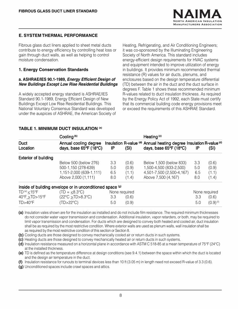
E. SYSTEM THERMAL PERFORMANCE
Fibrous glass duct liners applied to sheet metal ductscontribute to energy efficiency by controlling heat loss orgain through duct walls, as well as helping to controlmoisture condensation.
1. Energy Conservation Standards
a. ASHRAE/IES 90.1-1989, Energy Efficient Design ofNew Buildings Except Low Rise Residential Buildings
A widely accepted energy standard is ASHRAE/IESStandard 90.1-1989, Energy Efficient Design of NewBuildings Except Low Rise Residential Buildings. ThisNational Voluntary Consensus Standard was developedunder the auspices of ASHRAE, the American Society of
TABLE 1. MINIMUM DUCT INSULATION (a)
CoolingCoolingCoolingCoolingCooling (b) (b) (b) (b) (b) HeatingHeatingHeatingHeatingHeating (c) (c) (c) (c) (c)
DuctDuctDuctDuctDuct Annual cooling degrAnnual cooling degrAnnual cooling degrAnnual cooling degrAnnual cooling degreeeeeeeeee Insulation R-value Insulation R-value Insulation R-value Insulation R-value Insulation R-value (d)(d)(d)(d)(d) Annual heating degrAnnual heating degrAnnual heating degrAnnual heating degrAnnual heating degreeeeeeeeee Insulation R-value Insulation R-value Insulation R-value Insulation R-value Insulation R-value (d)(d)(d)(d)(d)
LocationLocationLocationLocationLocation days, base 65°F (18°C)days, base 65°F (18°C)days, base 65°F (18°C)days, base 65°F (18°C)days, base 65°F (18°C) IP (SI) IP (SI) IP (SI) IP (SI) IP (SI) days, base 65°F (18°C) IP (SI)days, base 65°F (18°C) IP (SI)days, base 65°F (18°C) IP (SI)days, base 65°F (18°C) IP (SI)days, base 65°F (18°C) IP (SI)
Exterior of buildingExterior of buildingExterior of buildingExterior of buildingExterior of buildingBelow 500 (below 276) 3.3 (0.6) Below 1,500 (below 833) 3.3 (0.6)500-1,150 (278-639) 5.0 (0.9) 1,500-4,500 (833-2,500) 5.0 (0.9)1,151-2,000 (639-1,111) 6.5 (1.1) 4,501-7,500 (2,500-4,167) 6.5 (1.1)Above 2,000 (1,111) 8.0 (1.4) Above 7,500 (4,167) 8.0 (1.4)
Inside of building envelope or in unconditioned space Inside of building envelope or in unconditioned space Inside of building envelope or in unconditioned space Inside of building envelope or in unconditioned space Inside of building envelope or in unconditioned space (g)(g)(g)(g)(g)
TD (e) <15°F (TD = <8.3°C) None required None required40°F >TD>15°F (22°C >TD>8.3°C) 3.3 (0.6) 3.3 (0.6)TD>40°F (TD>22°C) 5.0 (0.9) 5.0 (0.9) (f)
(a)(a)(a)(a)(a) Insulation vales shown are for the insulation as installed and do not include film resistance. The required minimum thicknessesdo not consider water vapor transmission and condensation. Additional insulation, vapor retarders, or both, may be required tolimit vapor transmission and condensation. For ducts which are designed to convey both heated and cooled air, duct insulationshall be as required by the most restrictive condition. Where exterior walls are used as plenum walls, wall insulation shall beas required by the most restrictive condition of this section or Section 8.
(b)(b)(b)(b)(b) Cooling ducts are those designed to convey mechanically cooled air or return ducts in such systems.(c)(c)(c)(c)(c) Heating ducts are those designed to convey mechanically heated air or return ducts in such systems.(d)(d)(d)(d)(d) Insulation resistance measured on a horizontal plane in accordance with ASTM C 518-85 at a mean temperature of 75°F (24°C)
at the installed thickness.(e)(e)(e)(e)(e) TD is defined as the temperature difference at design conditions (see 9.4.1) between the space within which the duct is located
and the design air temperature in the duct.(f)(f)(f)(f)(f) Insulation resistance for runouts to terminal devices less than 10 ft (3.05 m) in length need not exceed R-value of 3.3 (0.6).(g)(g)(g)(g)(g) Unconditioned spaces include crawl spaces and attics.
Heating, Refrigerating, and Air Conditioning Engineers;it was co-sponsored by the Illuminating EngineeringSociety of North America. This standard includesenergy-efficient design requirements for HVAC systemsand equipment intended to improve utilization of energyin buildings. It provides minimum recommended thermalresistance (R) values for air ducts, plenums, andenclosures based on the design temperature differential(TD) between the air in the duct and the duct surface indegrees F. Table 1 shows these recommended minimumR-values related to duct insulation thickness. As requiredby the Energy Policy Act of 1992, each State must certifythat its commercial building code energy provisions meetor exceed the requirements of this ASHRAE Standard.
NAIMANorth American Insulation
Manufacturers Association

b. ANSI/ASHRAE/IESNA 90.1-2001, Energy Standardfor Buildings Except Low Rise Residential Buildings
This National Voluntary Consensus Standard wasdeveloped under the auspices of ASHRAE, the AmericanSociety of Heating, Refrigerating, and Air ConditioningEngineers; it was co-sponsored by both the AmericanNational Standards Institute (ANSI) and the IlluminatingEngineering Society of North America. It supersedes
FIBROUS GLASS DUCT LINER STANDARD
9
ASHRAE/IES 90.1-1989. Minimum duct systemR-values are keyed to building envelope criteria tablesfound in Appendix B of the Standard, and to climate zoneconditions found in Appendix D. Minimum R-values aregiven in Tables 6.2.4.2A below and 6.2.4.2B on page 10.
TABLE 6.2.4.2A. MINIMUM DUCT INSULATION R-VALUE,(a)
COOLING AND HEATING ONLY SUPPLY DUCTS AND RETURN DUCTS
Climate Zone Duct LocationUnvented UnventedAttic with Attic with Uncon- Indirectly
Envelope Ventilated Backloaded Roof ditioned conditionedCriteria Table HDD65 CDD50 Exterior Attic Ceiling Insulation Space(b) Space(c) Buried
Heating Ducts OnlyB-1 to B-7 0-1800 all none none none none none none noneB-8 to B-12 1801-3600 all R-3.5 none none none none none noneB-13 to B-15 3601-5400 all R-3.5 none none none none none noneB-16 to B-18 5401-7200 all R-6 R-3.5 none none none none R-3.5B-19 to B-20 7201-9000 all R-6 R-6 R-3.5 none none none R-3.5B-21 to B-22 9001-10800 all R-8 R-6 R-6 none R-3.5 none R-3.5
B-23 10801-12600 all R-8 R-6 R-6 none R-6 none R-6B-24 12601-16200 all R-8 R-8 R-6 none R-6 none R-6B-25 16201-19800 all R-10 R-8 R-8 none R-6 none R-6B-26 19801+ all R-10 R-10 R-8 none R-8 none R-6
Cooling Only DuctsB-15,18, 20, all 0 – 1800 R-1.9 R-1.9 R-1.9 R-1.9 R-1.9 none none
22 to 26B-12,14,17, all 1801-3600 R-3.5 R-1.9 R-3.5 R-1.9 R-1.9 none none
19, 21B-7,9,11,13,16 all 3601-5400 R-3.5 R-3.5 R-6 R-1.9 R-1.9 none noneB-4, 6, 8, 10 all 5401-7200 R-6 R-6 R-6 R-3.5 R-1.9 none none
B-3, B-5 all 7201-9000 R-6 R-6 R-6 R-3.5 R-3.5 none R-3.5B-2 all 9001-10800 R-6 R-6 R-8 R-3.5 R-3.5 none R-3.5B-1 all 10801+ R-8 R-8 R-8 R-3.5 R-3.5 none R-3.5
Return DuctsB-1 to B-26 all climates R-3.5 R-3.5 R-3.5 none none none none
(a) Insulation R-values, measured in (hr•ft2•°F)/Btu, are for the insulation as installed and do not include film resistance. The requiredminimum thicknesses do not consider water vapor transmission and possible surface condensation. Where exterior walls are usedas plenum walls, wall insulation shall be as required by the most restrictive condition of 6.2.4.2 or Section 5. Insulation resistancemeasured on a horizontal plane in accordance with ASTM C518 at a mean temperature of 75°F at the installed thickness.
(b) Includes crawl spaces, both ventilated and non-ventilated.(c) Includes return air plenums with or without exposed roofs above.
NAIMANorth American Insulation
Manufacturers Association

10
FIBROUS GLASS DUCT LINER STANDARD
TABLE 6.2.4.2B. MINIMUM DUCT INSULATION R-VALUE,COMBINED HEATING AND COOLING DUCTS
Climate Zone Duct LocationUnvented UnventedAttic with Attic with Uncon- Indirectly
Envelope Ventilated Backloaded Roof ditioned conditionedCriteria Table HDD65 CDD50 Exterior Attic Ceiling Insulation Space(b) Space(c) Buried
B-1 0 - 900 10801+ R-8 R-6 R-8 R-3.5 R-3.5 none R-3.5B-2 0 - 900 9001-10800 R-6 R-6 R-8 R-3.5 R-3.5 none R-3.5B-3 0 - 900 7201-9000 R-6 R-6 R-6 R-3.5 R-3.5 none R-3.5B-4 0 - 900 0 - 7200 R-6 R-3.5 R-6 R-3.5 R-1.9 none R-3.5B-5 901-1800 7201+ R-6 R-6 R-6 R-3.5 R-3.5 none R-3.5B-6 901-1800 5401-7200 R-6 R-6 R-6 R-3.5 R-3.5 none R-3.5B-7 901-1800 0-5400 R-3.5 R-3.5 R-6 R-1.9 R-1.9 none R-1.9B-8 1801-2700 5401+ R-6 R-6 R-6 R-3.5 R-3.5 none R-3.5B-9 1801-2700 0-5400 R-6 R-3.5 R-6 R-1.9 R-1.9 none R-1.9
B-10 2701-3600 5401+ R-6 R-6 R-6 R-3.5 R-3.5 none R-3.5B-11 2701-3600 3601-5400 R-6 R-6 R-6 R-3.5 R-3.5 none R-1.9B-12 2701-3600 0-3600 R-3.5 R-3.5 R-3.5 R-1.9 R-1.9 none R-1.9B-13 3601-5400 3601+ R-6 R-6 R-6 R-3.5 R-3.5 none R-3.5B-14 3601-5400 1801-3600 R-6 R-3.5 R-6 R-1.9 R-3.5 none R-1.9B-15 3601-5400 0-1800 R-3.5 R-3.5 R-3.5 R-1.9 R-1.9 none R-1.9B-16 5401-7200 3601+ R-6 R-6 R-6 R-3.5 R-3.5 none R-3.5B-17 5401-7200 1801-3600 R-6 R-6 R-6 R-1.9 R-3.5 none R-3.5B-18 5401-7200 0-1800 R-6 R-3.5 R-3.5 R-1.9 R-3.5 none R-3.5B-19 7201-9000 1801+ R-8 R-6 R-6 R-1.9 R-3.5 none R-3.5B-20 7201-9000 0-1800 R-6 R-6 R-6 R-1.9 R-3.5 none R-3.5B-21 9001-10800 1801+ R-8 R-6 R-6 R-1.9 R-6 none R-3.5B-22 9001-10800 0-1800 R-8 R-6 R-6 R-1.9 R-3.5 none R-3.5B-23 10801-12600 all R-8 R-6 R-6 R-1.9 R-6 none R-6B-24 12601-16200 all R-8 R-8 R-8 R-1.9 R-6 none R-6B-25 16201-19800 all R-10 R-8 R-8 R-3.5 R-6 none R-6B-26 19801+ all R-10 R-10 R-8 R-3.5 R-8 R-3.5 R-6
(a) Insulation R-values, measured in (hr•ft2•°F)/Btu, are for the insulation as installed and do not include film resistance. Therequired minimum thicknesses do not consider water vapor transmission and possible surface condensation. Where exteriorwalls are used as plenum walls, wall insulation shall be as required by the most restrictive condition of 6.2.4.2 or Section 5. Insulationresistance measured on a horizontal plane in accordance with ASTM C518 at a mean temperature of 75°F at the installed thickness.
(b) Includes crawl spaces, both ventilated and non-ventilated.(c) Includes return air plenums with or without exposed roofs above.
NAIMANorth American Insulation
Manufacturers Association
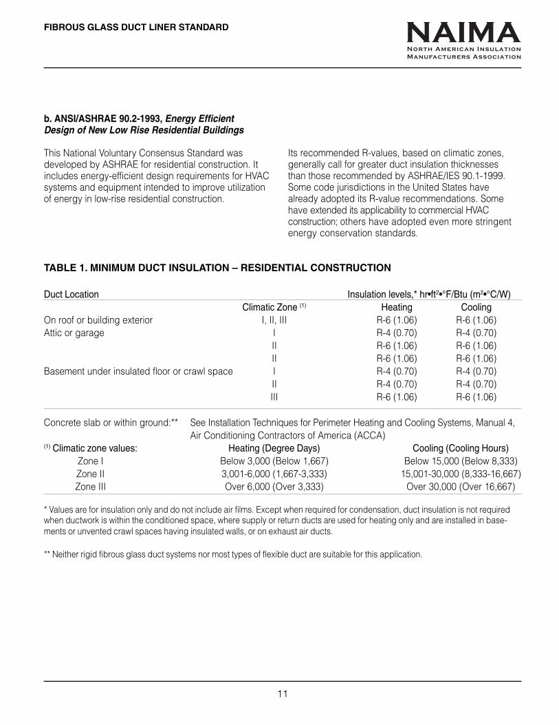
b. ANSI/ASHRAE 90.2-1993, Energy EfficientDesign of New Low Rise Residential Buildings
This National Voluntary Consensus Standard wasdeveloped by ASHRAE for residential construction. Itincludes energy-efficient design requirements for HVACsystems and equipment intended to improve utilizationof energy in low-rise residential construction.
FIBROUS GLASS DUCT LINER STANDARD
11
TABLE 1. MINIMUM DUCT INSULATION – RESIDENTIAL CONSTRUCTION
Duct Location Insulation levels,* hr•ft2•°F/Btu (m2•°C/W)Climatic Zone (1) Heating Cooling
On roof or building exterior I, II, III R-6 (1.06) R-6 (1.06)Attic or garage I R-4 (0.70) R-4 (0.70)
II R-6 (1.06) R-6 (1.06)II R-6 (1.06) R-6 (1.06)
Basement under insulated floor or crawl space I R-4 (0.70) R-4 (0.70)II R-4 (0.70) R-4 (0.70)III R-6 (1.06) R-6 (1.06)
Concrete slab or within ground:** See Installation Techniques for Perimeter Heating and Cooling Systems, Manual 4,Air Conditioning Contractors of America (ACCA)
(1) Climatic zone values: Heating (Degree Days) Cooling (Cooling Hours)Zone I Below 3,000 (Below 1,667) Below 15,000 (Below 8,333)Zone II 3,001-6,000 (1,667-3,333) 15,001-30,000 (8,333-16,667)Zone III Over 6,000 (Over 3,333) Over 30,000 (Over 16,667)
* Values are for insulation only and do not include air films. Except when required for condensation, duct insulation is not requiredwhen ductwork is within the conditioned space, where supply or return ducts are used for heating only and are installed in base-ments or unvented crawl spaces having insulated walls, or on exhaust air ducts.
** Neither rigid fibrous glass duct systems nor most types of flexible duct are suitable for this application.
Its recommended R-values, based on climatic zones,generally call for greater duct insulation thicknessesthan those recommended by ASHRAE/IES 90.1-1999.Some code jurisdictions in the United States havealready adopted its R-value recommendations. Somehave extended its applicability to commercial HVACconstruction; others have adopted even more stringentenergy conservation standards.
NAIMANorth American Insulation
Manufacturers Association

FIBROUS GLASS DUCT LINER STANDARD
12
F. CONDENSATION CONTROL PERFORMANCE
Fibrous glass duct liners are effective in helping tocontrol moisture condensation on both interior andexterior surfaces of sheet metal ductwork. This helpsthe insulation to stay dry, maintaining its full thermalefficiency. It also helps to prevent damage to ceilingsand other building components caused by condensationdripping from ductwork.
The charts below show installed R-values of fibrous glassduct liner required to prevent moisture condensation on theoutside surface of the duct under varying conditions ofambient temperature and relative humidity. Curves are basedon cold duct internal temperature of 55oF (13oC), no wind.
60 65 70 75 80 85 90 95 100(16) (18) (20) (22) (25) (28) (32) (35) (38)
12
10
8
6
4
2
2.11
1.76
1.41
1.06
0.72
0.36
REQUIRED R-VALUE, EMISSIVITY 0.1
90O/O 70O/O
80O/O 60O/O
R-V
AL
UE
(IP
), h
r ·ft2 ·o
F/B
tu
R V
AL
UE
(S
I), m
2 ·o C/W
60 65 70 75 80 85 90 95 100(16) (18) (20) (22) (25) (28) (32) (35) (38)
12
10
8
6
4
2
2.11
1.76
1.41
1.06
0.72
0.36
REQUIRED R-VALUE, EMISSIVITY 0.9
90O/O 70O/O
80O/O 60O/O
AMBIENT TEMPERATURE, 0F (0C)
AMBIENT TEMPERATURE, 0F (0C)
R-V
AL
UE
(IP
), h
r ·ft2 ·o
F/B
tu
R V
AL
UE
(S
I), m
2 ·o C/W
SHADED AREA: R-VALUES REQUIRED BY ASHRAE 90.1 - 1989
SHADED AREA: R-VALUES REQUIRED BY ASHRAE 90.1 - 1989
NAIMANorth American Insulation
Manufacturers Association

FIBROUS GLASS DUCT LINER STANDARD
13
G. INDOOR ENVIRONMENTAL QUALITY ANDDUCT INSULATION
When properly designed, installed, operated andmaintained, air transmission systems with fibrous glassduct liners can enhance indoor environmental quality bycontrolling heat loss or gain while reducing condensationand providing control of duct-borne noise.
Tests on fibrous glass duct liners have not indicatedsignificant fiber contribution to the occupied space.In fact, test samples contained fewer fibers than valuesreported for outdoor ambient air. Reviewing a number ofmajor studies, the World Health Organization’s InternationalProgramme on Chemical Safety (1988) concluded: “Thecontribution of fibrous-glass-lined air transmission systemsto the fibre content of indoor air is insignificant.”
It is vital that HVAC systems be properly designed,installed, operated and maintained, to minimize moisturecarry-over from humidifiers and/or cooling coils by the airstream into the duct system. High efficiency filtrationshould be selected and regularly maintained to reducedirt accumulation in the duct system and the possibility ofmicrobial contamination. Condensate drains must also beinspected to assure that they are operating properly.
H. FIRE SAFETY CONSIDERATIONS
Excerpts from NFPA Standard 90A, Standard for theInstallation of Air Conditioning and Ventilating Systems,1999 Edition
DEFINITIONS:
Air Duct Lining.Air Duct Lining.Air Duct Lining.Air Duct Lining.Air Duct Lining. Air duct lining includes materials suchas adhesive, insulation, coating, and film used to line theinside surface of an air duct, fan casing, or duct plenum.Air ducts shall be constructed of materials, reinforced andsealed to satisfy the requirements of use of the air ductsystem such as supply air systems, return or exhaust airsystems, and variable volume/pressure air systems.
Limited Combustible Material.Limited Combustible Material.Limited Combustible Material.Limited Combustible Material.Limited Combustible Material. A building constructionmaterial not complying with the definition of noncombustiblematerial, which, in the form in which it is used, has apotential heat value not exceeding 3,500 Btu/lb (8141 kJ/kg)where tested in accordance with NFPA 259, Standard TestMethod for Potential Heat of Building Materials, andcomplies with (a) or (b):
(a) Materials having a structural base of noncombustiblematerial, with a surfacing not exceeding a thickness of 1/8"(3.2 mm), that has a flame spread index not greater than 50.
(b) Materials, in the form and thickness used, other thanas described in (a), having neither a flame spread indexgreater than 25 nor evidence of continued progressivecombustion, and of such composition that surfaces thatwould be exposed by cutting through the material on anyplane would have neither a flame spread index greater than25 nor evidence of continued progressive combustion.
Materials subject to increase in combustibility or flamespread index beyond the limits herein established throughthe effects of age, moisture, or other atmospheric conditionshall be considered combustible.
When supplementarWhen supplementarWhen supplementarWhen supplementarWhen supplementary materialsy materialsy materialsy materialsy materials such as duct coverings,duct linings, vapor barrier facings, fasteners, tapes, andcore materials added to air ducts, plenums, panels, andduct silencers are to be applied with adhesives, theyshall be tested with such adhesives applied, or theadhesives used shall have a maximum flame spreadindex of 25 and a maximum smoke developed index of50 when in the final dry state.
Air duct, panel and plenum liningsAir duct, panel and plenum liningsAir duct, panel and plenum liningsAir duct, panel and plenum liningsAir duct, panel and plenum linings shall not flame,glow, smolder or smoke when tested in accordance withsimilar test for pipe covering, ASTM C 411, Standard TestMethod for Hot-Surface Performance of High TemperatureThermal Insulation, at the temperature to which they areexposed in service. In no case shall the test temperaturebe below 250°F (121°C).
Air duct linings shall be interrupted at fire dampers so asnot to interfere with the operation of these devices. (Seepage 23 for installation details.)
NAIMANorth American Insulation
Manufacturers Association

14
FIBROUS GLASS DUCT LINER STANDARD
I. DESIGN CONSIDERATIONS
When determining the application of fibrous glass ductliner in an air duct system, the designer should consider:
1. USES SUBJECT TO INDICATEDPRECAUTIONS
• Duct liner should only be used in systems whereoperating temperatures will not exceed 250°F (121°C).
• To avoid contact with liquid water, duct liner shall beprotected by use of a sheet metal sleeve and drip panadjacent to such equipment as evaporative coolers,humidifiers, cooling coils, and outside air intakes.
• When duct systems run through unconditioned spaceand are used for cooling only, register openings mustbe tightly sealed during the heating season to preventaccumulation of water vapor in the duct system.
• To avoid damage to the duct liner due to the physicalabuse caused by maintenance personnel working inaccessible plenums, some means of duct linerprotection must be considered.
• Lined ductwork supplying clean rooms should haveterminal filtration of the efficiency required for theparticular class of clean rooms.
2. APPLICATION LIMITATIONS
The use of fibrThe use of fibrThe use of fibrThe use of fibrThe use of fibrous glass duct liner is not rous glass duct liner is not rous glass duct liner is not rous glass duct liner is not rous glass duct liner is not recommendedecommendedecommendedecommendedecommendedfor the following applications:for the following applications:for the following applications:for the following applications:for the following applications:
• With equipment of any type which does not includeautomatic maximum temperature controls and wherean operating temperature of 250°F (121°C) may beexceeded.
• In kitchen or fume exhaust ducts, or ducts conveyingsolids or corrosive gases.
• With coal or wood fueled equipment.• In any application where the duct liner may come in
direct contact with liquid water (such as cooling coils,humidifiers, evaporative coolers) unless protectedfrom the water source.
• Inside fire damper sleeves. (See page 23 for details ofduct liner interruption at fire dampers.)
• Immediately adjacent to high temperature heatingcoils without radiation protection.
• In systems supplying operating rooms, delivery rooms,recovery rooms, nurseries, isolation rooms, andintensive care.
NAIMANorth American Insulation
Manufacturers Association
FIBROUS GLASS DUCT LINER STANDARD
15
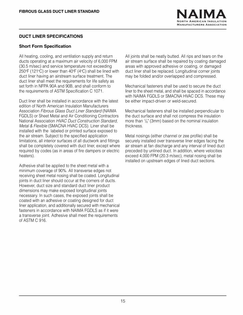
DUCT LINER SPECIFICATIONS
Short Form Specification
All heating, cooling, and ventilation supply and returnducts operating at a maximum air velocity of 6,000 FPM(30.5 m/sec) and service temperature not exceeding250oF (121oC) or lower than 40oF (4oC) shall be lined withduct liner having an airstream surface treatment. Theduct liner shall meet the requirements for life safety asset forth in NFPA 90A and 90B, and shall conform tothe requirements of ASTM Specification C 1071.
Duct liner shall be installed in accordance with the latestedition of North American Insulation ManufacturersAssociation Fibrous Glass Duct Liner Standard (NAIMAFGDLS) or Sheet Metal and Air Conditioning ContractorsNational Association HVAC Duct Construction Standard,Metal & Flexible (SMACNA HVAC DCS). Liner shall beinstalled with the labeled or printed surface exposed tothe air stream. Subject to the specified applicationlimitations, all interior surfaces of all ductwork and fittingsshall be completely covered with duct liner, except whererequired by codes (as in areas of fire dampers or electricheaters).
Adhesive shall be applied to the sheet metal with aminimum coverage of 90%. All transverse edges notreceiving sheet metal nosing shall be coated. Longitudinaljoints in duct liner should occur at the corners of ducts.However, duct size and standard duct liner productdimensions may make exposed longitudinal jointsnecessary. In such cases, the exposed joints shall becoated with an adhesive or coating designed for ductliner application, and additionally secured with mechanicalfasteners in accordance with NAIMA FGDLS as if it werea transverse joint. Adhesive shall meet the requirementsof ASTM C 916.
All joints shall be neatly butted. All rips and tears on theair stream surface shall be repaired by coating damagedareas with approved adhesive or coating, or damagedduct liner shall be replaced. Longitudinal corner jointsmay be folded and/or overlapped and compressed.
Mechanical fasteners shall be used to secure the ductliner to the sheet metal, and shall be spaced in accordancewith NAIMA FGDLS or SMACNA HVAC DCS. These maybe either impact-driven or weld-secured.
Mechanical fasteners shall be installed perpendicular tothe duct surface and shall not compress the insulationmore than 1/8" (3mm) based on the nominal insulationthickness.
Metal nosings (either channel or zee profile) shall besecurely installed over transverse liner edges facing theair stream at fan discharge and any interval of lined ductpreceded by unlined duct. In addition, where velocitiesexceed 4,000 FPM (20.3 m/sec), metal nosing shall beinstalled on upstream edges of lined duct sections.
NAIMANorth American Insulation
Manufacturers Association

16
FIBROUS GLASS DUCT LINER STANDARD
CSI 3-Part MASTERFORMAT ® Specification
SECTION 15812Sheet Metal Ducts - Acoustical Lining InsulationCommercial/Residential Duct Systems
PART 1.00 - GENERAL1.01 Scope
A.A.A.A.A. The work covered by this specification consists offurnishing all labor, equipment, materials and accessories,and performing all operations required, for correct fabricationand installation of commercial or residential air duct systemsof sheet metal lined with fibrous glass duct liner, in accordancewith applicable project drawings and specifications,subject to terms and conditions of the contract:
1.1.1.1.1. All air duct systems operating at internal air velocitiesnot exceeding rated duct liner limitations and internal airtemperature not exceeding 250oF (121oC) nor below 40oF (4oC).
2.2.2.2.2. Duct liner products shall conform to the requirementsof ASTM C 1071.
3.3.3.3.3. The manufacturer’s product identification shall appearon the air stream surface.
4.4.4.4.4. Duct liner adhesive shall conform to the requirementsof ASTM C 916.
5.5.5.5.5. The finished duct system shall meet the requirementsof NFPA 90A and 90B including:
• It shall be rated for maximum operatingtemperature of 250oF (121oC) per ASTM C 411.
• It shall have a flame spread index not greaterthan 25 and a smoke developed index notgreater than 50 per NFPA 255 (ASTM E 84).
• It shall have a potential heat value not greaterthan 3500 Btu/lb (8141 kJ/kg) per NFPA 259.
• It shall have no microbial growth when tested perASTM C 1338, ASTM G 21-96 (fungus test) andASTM G 22-96 (bacteria test).
Marking on the airstream surface of the duct liner shallprovide evidence of compliance.
B.B.B.B.B. Dimensions shown on the plans are finished insidedimensions.
C.C.C.C.C. Fabrication and installation shall conform tomanufacturer’s recommendations and to the requirementsof the latest edition of North American InsulationManufacturers Association Fibrous Glass Duct LinerStandard (hereinafter referred to as NAIMA FGDLS) or ofSheet Metal and Air Conditioning Contractors NationalAssociation HVAC Duct Construction Standards - Metal andFlexible (hereinafter referred to as SMACNA HVAC DCS).
1.02 Delivery and Storage of Materials
A.A.A.A.A. Deliver all materials and/or fabricated, insulated ductsections and fittings to the job site and store in a safe,dry place.
B.B.B.B.B. Protect materials from dust, dirt, moisture, andphysical abuse before and during installation. Replacewet, contaminated duct liner.
PART 2.00 - PRODUCTS2.01 Insulated Duct System
A. Insulate all supply ducts, return ducts, and relatedfittings with duct liner meeting the requirements ofASTM C 1071 as follows:
1.1.1.1.1. Type I - Flat, in roll form, in thicknesses of 1/2” to 2”(13mm to 51mm) in 1/2” (13mm) increments. Maximumthermal conductivity at 75°F (24°C) mean temperature:0.31 Btu·in/hr·ft2·°F ( = 0.045 W/m·°C).
2. Type II - Flat, in sheet form, in thicknesses of 1”, 11/2”,and 2”(25mm, 38mm, and 51mm).,Maximum thermal conductivity at 75°F (24°C) meantemperature: 0.27 Btu·in/hr·ft2·°F ( = 0.039 W/m·oC).The duct liner shall have an airstream surface treatment.
PART 3.00 - EXECUTION3.01 Inspection
A.A.A.A.A. Verify that the duct liner product may be installed inaccordance with project drawings, operating performanceparameters and limitations, and provisions of NAIMAFGDLS or SMACNA HVAC DCS.
3.02 Insulation of Straight Ducts and Fittings
A.A.A.A.A. Cover completely with duct liner all portions of ductdesignated to receive duct liner. Neatly butt all joints.Install duct liner with the labeled or printed surfaceexposed to the air stream.
B.B.B.B.B. Adhere duct liner to sheet metal with 90% (min.) coverageof adhesive complying with requirements of ASTM C 916.
C.C.C.C.C. Coat all transverse edges not receiving sheet metalnosing. Longitudinal joints in duct liner should occur atthe corners of ducts. However, duct size and standardduct liner product dimensions may make exposed
NAIMANorth American Insulation
Manufacturers Association
FIBROUS GLASS DUCT LINER STANDARD
17
D.D.D.D.D. Additionally secure duct liner with mechanicalfasteners, either weld-secured or impact-driven.Mechanical fasteners shall not compress the insulationmore than 1/8" (3 mm) based on nominal insulationthickness, and shall be installed perpendicular to theduct surface. Spacing of mechanical fasteners withrespect to interior duct dimensions shall be inaccordance with NAIMA FGDLS or SMACNA HVAC DCS.Fastener heads or washers shall have a minimum area of0.75 in.2 (480mm2) with beveled or cupped edges.
E.E.E.E.E. Securely install metal nosings (either channel or zeeprofile) over transverse liner edges facing the airstreamat fan discharge and at any point where lined duct ispreceded by unlined duct. In addition, where airvelocities exceed 4,000 FPM (20.3 m/sec), install metalnosing on upstream edges of lined duct sections.
FFFFF..... Fold duct liner in roll form and compress in the cornersof rectangular duct sections, or cut and fit to assure alapped, compressed corner joint.
G.G.G.G.G.Cut and fit duct liner in sheet form to assure tight,overlapped corner joints. Install so top pieces of rigidduct liner are supported at the edges by the side pieces.
H.H.H.H.H. Installation of two layers of duct liner is not recommended.If the specification forces the use of multiple layers, thefollowing steps shall be taken:
1.1.1.1.1. Adhere first layer of duct liner to the sheet metal inthe usual manner.
2.2.2.2.2. Adhere top layer of duct liner to bottom layer usinga minimum of 90% adhesive coverage.
3.3.3.3.3. Use mechanical fasteners of the proper length forthe double layer of duct liner.
4.4.4.4.4. Treat the leading edges of double layer duct liningsto prevent separation of the two layers in accordancewith requirements for single layer applications(determined by service air velocity).
3.03 Inspection
A.A.A.A.A. Upon completion of installation of lined duct andbefore HVAC system start-up, visually inspect theductwork and verify that duct liner has been correctlyinstalled. Confirm that the duct system is free fromconstruction debris.
3.04 Commissioning
A.A.A.A.A. After the lined duct system is completely installed andready for service, conduct a final inspection of the entiresystem. This inspection should include, at minimum, thefollowing steps:
1.1.1.1.1. Check all registers, grilles, and diffusers to ensurethat they are clean and free from construction debris.
2.2.2.2.2. Check all filters in accordance with theirmanufacturers’ instructions. Use specified grade of filtersat all times system is operating.
3.3.3.3.3. Cover supply openings with filter media prior tosystem start-up to catch any loose material that mayremain inside the ductwork.
4.4.4.4.4. Turn the HVAC system on and allow it to run untilsteady state operation is reached.
5.5.5.5.5. Remove the temporary filter media from supplyopenings and, along with it, any loose material blowndownstream and caught by the filter media.
6.6.6.6.6. Check to ensure that air delivery performancemeets all requirements and complies with SMACNAleakage specifications.
3.05 Safety Precautions
A.A.A.A.A. Conduct all job site operations in compliance withapplicable provisons of the Occupational Safety andHealth Act, NAIMA’s Health and Safety PartnershipProgram (HSPP) and all state and/or local safety andhealth codes and regulations that may apply to the work.Consult manufacturer’s Material Safety Data Sheet(MSDS) when appropriate.
longitudinal joints necessary. In such cases, coatexposed joints with adhesive designed for duct linerapplication. Adhesive shall meet requirements ofASTM C 916. Additionally secure such joints withmechanical fasteners in accordance with NAIMAFGDLS as if they were transverse joints.
NAIMANorth American Insulation
Manufacturers Association
18
FIBROUS GLASS DUCT LINER STANDARD
SECTION II. FABRICATION STANDARDS
A. Application considerations
This Standard is based on the presumption that the ductsystem designer has:
1.1.1.1.1. Clearly designated on contract drawings the sectionsof ductwork to be lined;
2.2.2.2.2. Specified the type and thickness of duct liner to beinstalled, and adhesive to be used;
3.3.3.3.3. Determined that the specified duct liner has thethermal, acoustical, friction loss, and otherperformance characteristics required for the application;
4.4.4.4.4. Provided for condensation control where interruptionsof lined ductwork might cause a problem.
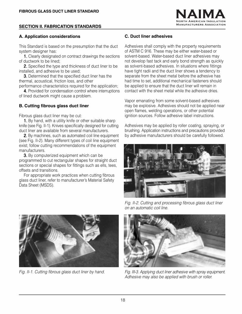
B. Cutting fibrous glass duct liner
Fibrous glass duct liner may be cut:1.1.1.1.1. By hand, with a utility knife or other suitable sharp
knife (see Fig. II-1). Knives specifically designed for cuttingduct liner are available from several manufacturers.
2.2.2.2.2. By machines, such as automated coil line equipment(see Fig. II-2). Many different types of coil line equipmentexist; follow cutting recommendations of the equipmentmanufacturers.
3.3.3.3.3. By computerized equipment which can beprogrammed to cut rectangular shapes for straight ductsections or special shapes for fittings such as ells, tees,offsets and transitions.
For appropriate work practices when cutting fibrousglass duct liner, refer to manufacturer’s Material SafetyData Sheet (MSDS).
C. Duct liner adhesives
Adhesives shall comply with the property requirementsof ASTM C 916. These may be either water-based orsolvent-based. Water-based duct liner adhesives maynot develop fast tack and early bond strength as quicklyas solvent-based adhesives. In situations where fittingshave tight radii and the duct liner shows a tendency toseparate from the sheet metal before the adhesive hashad time to set, additional mechanical fasteners shouldbe applied to ensure that the duct liner will remain incontact with the sheet metal while the adhesive dries.
Vapor emanating from some solvent-based adhesivesmay be explosive. Adhesives should not be applied nearopen flames, welding operations, or other potentialignition sources. Follow adhesive label instructions.
Adhesives may be applied by roller coating, spraying, orbrushing. Application instructions and precautions providedby adhesive manufacturers should be carefully followed.
Fig. II-1. Cutting fibrous glass duct liner by hand. Fig. III-3. Applying duct liner adhesive with spray equipment.Adhesive may also be applied with brush or roller.
Fig. II-2. Cutting and processing fibrous glass duct lineron an automatic coil line.
NAIMANorth American Insulation
Manufacturers Association

FIBROUS GLASS DUCT LINER STANDARD
19
D. Mechanical fastening
Mechanical fasteners shall be located with respect tointerior duct dimensions, regardless of air flow direction.See Fig. II-4.
See page 5 for types of mechanical fasteners.
Mechanical fasteners also must:1.1.1.1.1.Be as corrosion-resistant as G60 galvanized steel
when installed.2.2.2.2.2.Indefinitely sustain a 50 pound (22.7 Kg) tensile
dead load test perpendicular to the duct wall.3.3.3.3.3.Not adversely affect the fire hazard classification
of the duct liner and adhesive.4.4.4.4.4.Not damage the duct liner when applied as
recommended.
5.5.5.5.5.Not cause leakage in the duct.6.6.6.6.6.Be installed perpendicular to the duct surface.7.7.7.7.7.Be the correct length for the specified duct liner
thickness.8.8.8.8.8. Not compress the duct liner insulation more than
1/8” (3mm).9.9.9.9.9.Not project more than nominally into the air stream.
Fig. II-4. Mechanical fastener spacing
When velocity exceeds 4,000 FPM(20.3 m/sec), install metal nosing onedges of duct liner facing air stream.See page 21 for metal nosing details.
LAPPED ANDBUTTED CORNER
FOLDED CORNER
ALL TRANSVERSEEDGES COATED, AT
FACTORYOR SHOP APPLIED
NOMINALINSULATIONTHICKNESS
1/8" MAX.(3mm)
AIR FLOW
A
BD (TYP)
C (TYP)
D (TYP)B C
(TYP)
A
V V V V Velocityelocityelocityelocityelocity, feet per minute (meters per second), feet per minute (meters per second), feet per minute (meters per second), feet per minute (meters per second), feet per minute (meters per second)DimensionDimensionDimensionDimensionDimension 0-2,500 (0 - 12.7)0-2,500 (0 - 12.7)0-2,500 (0 - 12.7)0-2,500 (0 - 12.7)0-2,500 (0 - 12.7) 2,501-6000 (12.7 - 30.5)2,501-6000 (12.7 - 30.5)2,501-6000 (12.7 - 30.5)2,501-6000 (12.7 - 30.5)2,501-6000 (12.7 - 30.5)
A From corners of duct 4" (100mm) 4" (100mm)B From transverse end of duct liner 3" (75mm) 3" (75mm)C Across width of duct, on centers (min. 1 per side) 12" (300mm) 6" (150mm)D Along length of duct, on centers (min. 1 per side) 18" (450mm) 16" (400mm)
NAIMANorth American Insulation
Manufacturers Association

20
FIBROUS GLASS DUCT LINER STANDARD
E. General fabrication and installation principles
1.1.1.1.1. Unless otherwise indicated, the inside dimensions ofthe duct shown on contract drawings shall be maintained(see Fig. II-5). Duct dimensions shall be increased asnecessary to compensate for liner thickness.
Fig. II-5. Net free area
2.2.2.2.2. The duct liner shall cover 100% of the interior metalsurfaces of duct sections and fittings in finished form.Liner should not be patched in fittings, except that seamsmay be allowed at break points. Allowance for sheet metaladd-on dimensions must be made when cutting duct liner.
3.3.3.3.3. The duct liner shall be installed with the labeled orprinted surface exposed to the air stream.
4.4.4.4.4. The duct liner shall be adhered with a minimum of 90%coverage of adhesive of the liner contact surface area.Adhesive shall conform to ASTM C 916.
5.5.5.5.5. All transverse edges not receiving metal nosing shall befully coated with adhesive conforming to ASTM C 916 orcoating approved (or applied) by the duct liner manufacturer.Liner shall be neatly butted at all joints.
6.6.6.6.6. Liner shall be folded and compressed at corners ofrectangular duct sections, or cut and fit to assure lapped,compressed joints (see Figs. II-6a, b, c, page 21).Longitudinal joints in duct liner should occur at thecorners of ducts. However, duct size and standard ductliner product dimensions may make exposed longitudinaljoints necessary. In such cases, the exposed joints shallbe coated with adhesive and additionally secured withmechanical fasteners in accordance with NAIMA FibrousGlass Duct Liner Standard as if it were a transverse joint.
7.7.7.7.7. Metal nosings (either channel or zee profile) shall besecurely installed over transversely oriented liner edgesfacing the air stream at fan discharge and at any pointwhere lined duct is preceded by unlined duct (see Figs.II-7a, b, c, page 21). In addition, where air velocitiesexceed 4,000 fpm (20.3 m/sec), metal nosing shall beapplied to upstream edges of lined duct sections. Wheninstalling duct system components with nosings, makesure they are properly oriented with respect to thedirection of air flow.
8.8.8.8.8. Where dampers, turning vanes, or other devices areplaced inside of lined duct or fittings, the installation mustnot damage the airstream surface. The use of metal hatsections or other “build-out” means is optional; whenused, “build-outs” shall be mechanically secured to theduct wall. (See Fig. II-8, page 22.)
9.9.9.9.9. Duct liners shall be interrupted at fire dampers toavoid interference with damper operation, and at heatsources to meet minimum clearance specified as acondition of equipment listing. (See Fig. II-9, page 23.)
10. 10. 10. 10. 10. Installation of two layers of duct liner to meet aminimum specified thickness is not recommended. Whenspecifications require two layers, minimum adhesivecoverage of 90% for each layer shall be applied.Fasteners of sufficient length for both layers must beused. In addition, special attention to leading edgenosings is required (See Fig. II-7c, page 21).
NAIMANorth American Insulation
Manufacturers Association

FIBROUS GLASS DUCT LINER STANDARD
21
Fabrication Standard - Duct Liner Corner Treatments
Fig. II-6a. Type I duct liner, corners folded.
Fig. II-6b. Type I duct liner, corners lapped andcompressed.
Fig. II-6c. Type II duct liner, corners lapped, side piecessupporting top piece.
Longitudinal seams shall occur only at the corners of theduct unless duct size and standard duct liner productdimensions make it impossible to do so.
Nosing Treatments
Fig. II-7a. Channel nosing, 1" (25mm) x liner thickness x1" (25mm), mechanically secured to sheet metal duct.
Fig. II-7b. Zee nosing, 1" (25mm) x liner thickness x1" (25mm), mechanically secured to sheet metal duct.
Fig. II-7c. Nosing in two-layer duct liner installations,1" (25mm) x thickness of both layers x 1" (25mm).Second layer of duct liner shall also be adhered to firstlayer with 90% (minimum) coverage of adhesivecomplying with ASTM C 916. Duct liner fasteners mustbe of sufficient length for both layers of duct liner.
NAIMANorth American Insulation
Manufacturers Association
22
FIBROUS GLASS DUCT LINER STANDARD
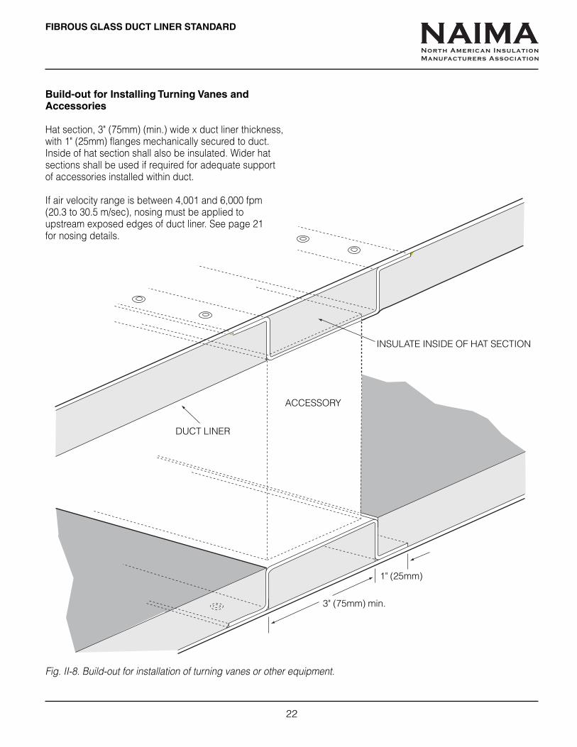
Build-out for Installing Turning Vanes andAccessories
Hat section, 3" (75mm) (min.) wide x duct liner thickness,with 1" (25mm) flanges mechanically secured to duct.Inside of hat section shall also be insulated. Wider hatsections shall be used if required for adequate supportof accessories installed within duct.
If air velocity range is between 4,001 and 6,000 fpm(20.3 to 30.5 m/sec), nosing must be applied toupstream exposed edges of duct liner. See page 21for nosing details.
Fig. II-8. Build-out for installation of turning vanes or other equipment.
ACCESSORY
3" (75mm) min.
DUCT LINER
INSULATE INSIDE OF HAT SECTION
1" (25mm)
NAIMANorth American Insulation
Manufacturers Association

FIBROUS GLASS DUCT LINER STANDARD
23
Fabrication Standard - Interruptions of DuctLiner (as at Fire Dampers)
Sleeve assembly installed through fire wall, securedto wall with retaining angle, per damper manufacturer’slisting. Duct shall be attached to sleeve assembly with“S” connectors. Exposed sleeve surfaces shall be insulatedwith duct wrap. Nosing is required on upstream exposededges of duct liner.
Fig. II-9. Interruption of duct liner, as at fire dampers.
EXTERNAL INSULATION
FIRE WALL
“S” CONNECTOR
AIR FLOW
NOSING ON UPSTREAMLINER EDGE
FIRE DAMPER
DAMPER SLEEVE
NAIMANorth American Insulation
Manufacturers Association
24
FIBROUS GLASS DUCT LINER STANDARD
SECTION III. SYSTEM OPERATION
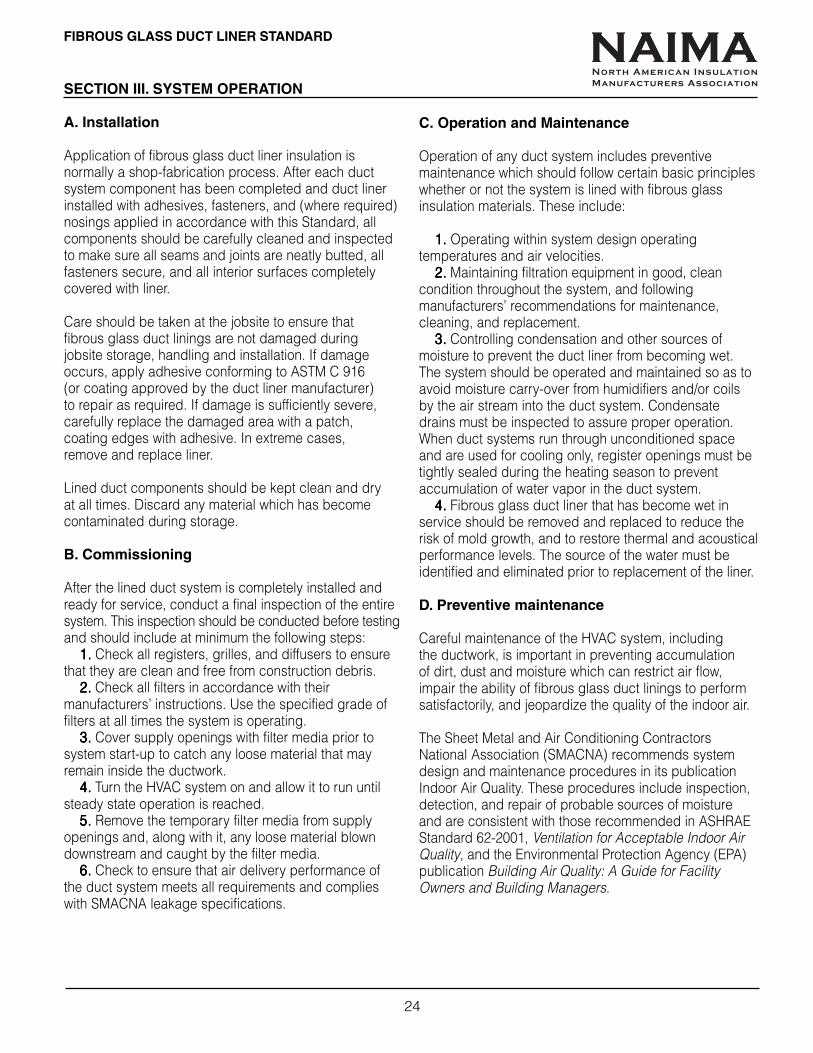
A. Installation
Application of fibrous glass duct liner insulation isnormally a shop-fabrication process. After each ductsystem component has been completed and duct linerinstalled with adhesives, fasteners, and (where required)nosings applied in accordance with this Standard, allcomponents should be carefully cleaned and inspectedto make sure all seams and joints are neatly butted, allfasteners secure, and all interior surfaces completelycovered with liner.
Care should be taken at the jobsite to ensure thatfibrous glass duct linings are not damaged duringjobsite storage, handling and installation. If damageoccurs, apply adhesive conforming to ASTM C 916(or coating approved by the duct liner manufacturer)to repair as required. If damage is sufficiently severe,carefully replace the damaged area with a patch,coating edges with adhesive. In extreme cases,remove and replace liner.
Lined duct components should be kept clean and dryat all times. Discard any material which has becomecontaminated during storage.
B. Commissioning
After the lined duct system is completely installed andready for service, conduct a final inspection of the entiresystem. This inspection should be conducted before testingand should include at minimum the following steps:
1.1.1.1.1. Check all registers, grilles, and diffusers to ensurethat they are clean and free from construction debris.
2.2.2.2.2. Check all filters in accordance with theirmanufacturers’ instructions. Use the specified grade offilters at all times the system is operating.
3.3.3.3.3. Cover supply openings with filter media prior tosystem start-up to catch any loose material that mayremain inside the ductwork.
4.4.4.4.4. Turn the HVAC system on and allow it to run untilsteady state operation is reached.
5.5.5.5.5. Remove the temporary filter media from supplyopenings and, along with it, any loose material blowndownstream and caught by the filter media.
6.6.6.6.6. Check to ensure that air delivery performance ofthe duct system meets all requirements and complieswith SMACNA leakage specifications.
C. Operation and Maintenance
Operation of any duct system includes preventivemaintenance which should follow certain basic principleswhether or not the system is lined with fibrous glassinsulation materials. These include:
1.1.1.1.1. Operating within system design operatingtemperatures and air velocities.
2.2.2.2.2. Maintaining filtration equipment in good, cleancondition throughout the system, and followingmanufacturers’ recommendations for maintenance,cleaning, and replacement.
3.3.3.3.3. Controlling condensation and other sources ofmoisture to prevent the duct liner from becoming wet.The system should be operated and maintained so as toavoid moisture carry-over from humidifiers and/or coilsby the air stream into the duct system. Condensatedrains must be inspected to assure proper operation.When duct systems run through unconditioned spaceand are used for cooling only, register openings must betightly sealed during the heating season to preventaccumulation of water vapor in the duct system.
4.4.4.4.4. Fibrous glass duct liner that has become wet inservice should be removed and replaced to reduce therisk of mold growth, and to restore thermal and acousticalperformance levels. The source of the water must beidentified and eliminated prior to replacement of the liner.
D. Preventive maintenance
Careful maintenance of the HVAC system, includingthe ductwork, is important in preventing accumulationof dirt, dust and moisture which can restrict air flow,impair the ability of fibrous glass duct linings to performsatisfactorily, and jeopardize the quality of the indoor air.
The Sheet Metal and Air Conditioning ContractorsNational Association (SMACNA) recommends systemdesign and maintenance procedures in its publicationIndoor Air Quality. These procedures include inspection,detection, and repair of probable sources of moistureand are consistent with those recommended in ASHRAEStandard 62-2001, Ventilation for Acceptable Indoor AirQuality, and the Environmental Protection Agency (EPA)publication Building Air Quality: A Guide for FacilityOwners and Building Managers.
NAIMANorth American Insulation
Manufacturers Association
FIBROUS GLASS DUCT LINER STANDARD
25
E. Accessing fibrous glass lined ducts forcleaning
In some cases, when preventive maintenance has beeninconsistent, system cleaning may become necessary.Fibrous glass duct liners can be cleaned successfully.Proper cleaning practices will ensure that the insulatedduct system’s structural and functional integrity ismaintained. The entire air distribution system needs to beopened, cleaned, closed, and returned to service with allits thermal, acoustical, and air-tightness properties intact.
Care must be taken in the selection and application ofthe cleaning process. Several viable methods areavailable which have proven effective in cleaninginsulated duct systems, and professional duct cleaningservices are widely available.
Refer to the NAIMA handbook, Cleaning Fibrous GlassInsulated Air Duct Systems, Pub. No. AH-122, for details.It is recommended that an independent expert be consultedbefore committing to proceed with duct cleaning,especially if introduction of “sanitizing” anti-microbialagents into the system is under consideration.
Opening ductwork
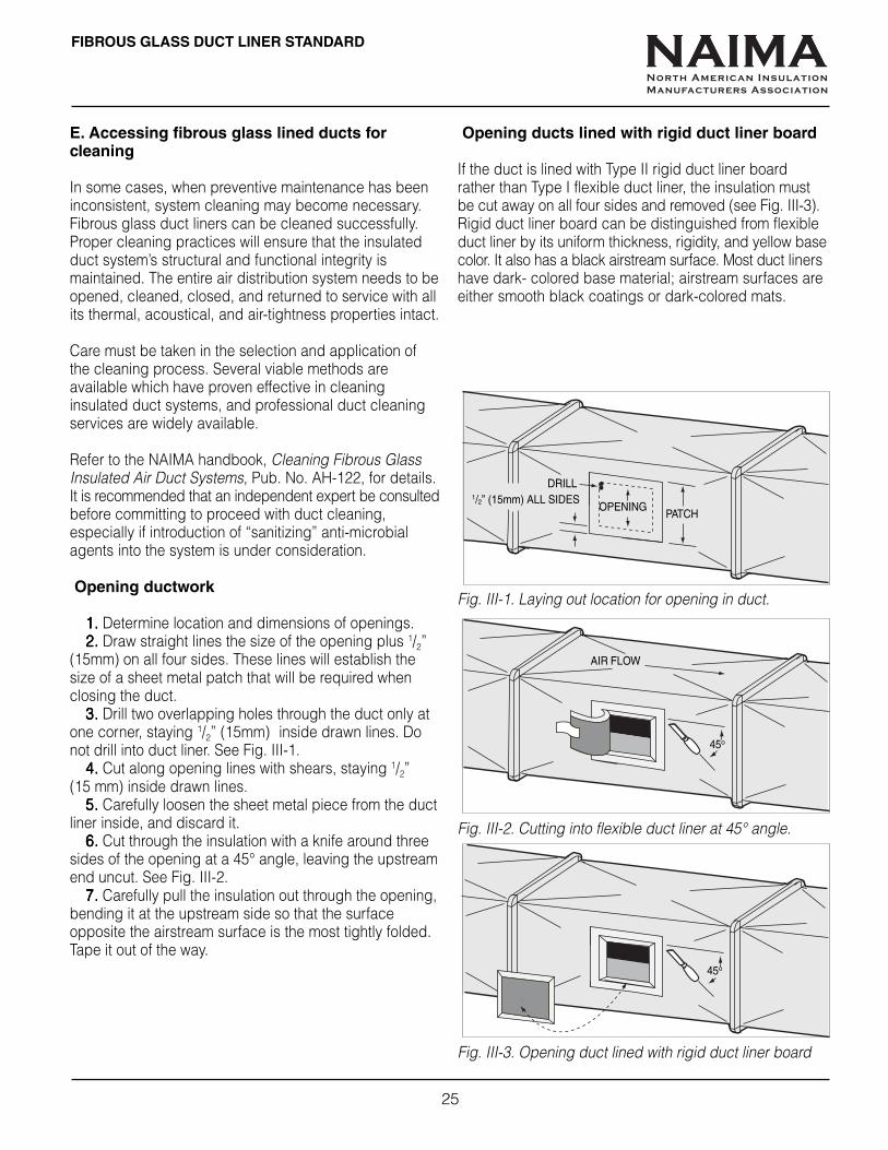
1.1.1.1.1. Determine location and dimensions of openings.2.2.2.2.2. Draw straight lines the size of the opening plus 1/2”
(15mm) on all four sides. These lines will establish thesize of a sheet metal patch that will be required whenclosing the duct.
3.3.3.3.3. Drill two overlapping holes through the duct only atone corner, staying 1/2” (15mm) inside drawn lines. Donot drill into duct liner. See Fig. III-1.
4.4.4.4.4. Cut along opening lines with shears, staying 1/2”(15 mm) inside drawn lines.
5.5.5.5.5. Carefully loosen the sheet metal piece from the ductliner inside, and discard it.
6.6.6.6.6. Cut through the insulation with a knife around threesides of the opening at a 45° angle, leaving the upstreamend uncut. See Fig. III-2.
7.7.7.7.7. Carefully pull the insulation out through the opening,bending it at the upstream side so that the surfaceopposite the airstream surface is the most tightly folded.Tape it out of the way.
Opening ducts lined with rigid duct liner board
If the duct is lined with Type II rigid duct liner boardrather than Type I flexible duct liner, the insulation mustbe cut away on all four sides and removed (see Fig. III-3).Rigid duct liner board can be distinguished from flexibleduct liner by its uniform thickness, rigidity, and yellow basecolor. It also has a black airstream surface. Most duct linershave dark- colored base material; airstream surfaces areeither smooth black coatings or dark-colored mats.
Fig. III-1. Laying out location for opening in duct.
Fig. III-2. Cutting into flexible duct liner at 45° angle.
Fig. III-3. Opening duct lined with rigid duct liner board
DRILL1/2” (15mm) ALL SIDES
OPENINGPATCH
45o
AIR FLOW
45o
NAIMANorth American Insulation
Manufacturers Association

26
FIBROUS GLASS DUCT LINER STANDARD
Closing cleaned ductwork
When closing openings made for cleaning sheet metalducts lined with fibrous glass duct liners, the insulationmust be secured in its original position before the sheetmetal is patched.
1.1.1.1.1. Coat edges of flexible duct liner flap (or cut-outpiece of rigid duct liner board) with adhesive complyingwith ASTM C 916.
2.2.2.2.2. Replace the flap or cut-out piece in its originalposition so the hole in the duct liner is tightly plugged(See Fig. III-4).
3.3.3.3.3. Cut a sheet metal patch to dimensions drawn onduct when opening (see page 25). The patch should beabout 1" (25mm) larger in both dimensions than the holein the sheet metal which it must cover.
4.4.4.4.4. Apply a bead of sealant around the opening (seeFig. III-5). Sealant must be suitable for use on sheet metalducts.
5.5.5.5.5. Apply adhesive to the duct liner flap or cut-outpiece of duct liner board, and press the sheet metalpatch in place over it.
6.6.6.6.6. Screw the sheet metal patch to the duct with sheetmetal screws on 8" (200mm) centers (approx.) so thepatch will overlap the opening by 1/2” (15mm), all foursides (see Fig. III-6).
PUSH BACKINTO
OPENINGADHESIVESON EDGES
SEALANTPATCH LINES
PATCH
SEALANT
SCREWS, 8” (200mm) O.C.
SCREWS MUSTNOT PENETRATEDUCT LINER
Fig. III-4. Replacing duct liner insulation after cleaning.
Fig. III-5. Sealing around opening and placing patch.
Fig. III-6. Fastening metal patch in place over opening.
NAIMANorth American Insulation
Manufacturers Association

FIBROUS GLASS DUCT LINER STANDARD
27
Inspection Check List for Fibrous Glass Duct Liner Installation
All check-marks should be in the YESYESYESYESYES column. If a check-mark appears in the NONONONONO column, it should be brought tothe duct system contractor’s attention.
Project Name and NumberDuct System ContractorMechanical ContractorGeneral ContractorEngineerInspected by Date
DOCUMENTATIONCurrent edition, NAIMA Fibrous Glass Duct Liner StandardSMACNA Duct Construction Standards - Metal and FlexibleDuct Liner Manufacturer’s Installation RecommendationsSubmittal DrawingsPlans and Job SpecificationsApplicable Building / Energy Codes
PRODUCT YES NO
Does duct liner comply with NFPA 90A as stated on product data sheet? ( ) ( )Does duct liner R-value conform to code requirements? ( ) ( )Is duct liner thickness in accordance with job plans and specifications? ( ) ( )
INSTALLATIONHas duct liner been correctly installed with labeled or printed surface visible? ( ) ( )Has duct liner been adhered to sheet metal with at least 90% coverage of adhesive? ( ) ( )Does duct liner completely cover all inside surfaces of system, including fittings? ( ) ( )Is the duct liner free of visible damage (tears, punctures, abrasions)? ( ) ( )Are fasteners of the proper type and properly installed? ( ) ( )Are fastener washers cupped or beveled, installed so they will not cut into duct liner? ( ) ( )Are fasteners spaced at the correct intervals for system air velocity? ( ) ( )Are fasteners correctly installed so they are perpendicular to the sheet metal? ( ) ( )Do fastener heads or washers compress duct liner no more than 1/8" (3mm)? ( ) ( )Are transverse joints factory coated, or field coated with adhesive meeting ASTM C 916? ( ) ( )Are all leading edges finished with sheet metal nosing if air velocity requires it? ( ) ( )Are transverse joints neatly butted? ( ) ( )Are all corner joints compressed and either overlapped or folded? ( ) ( )Are longitudinal joints at corners unless duct size or product dimensions prohibit? ( ) ( )Are top panels of duct liner board supported by side panels? ( ) ( )If installation is 2-layer, are layers bonded together with adhesive? ( ) ( )
COMMISSIONINGAre all sheet metal joints sealed per project specifications to prevent air leakage? ( ) ( )Has all construction debris been blown or physically removed from the duct system? ( ) ( )Are all registers, grilles and diffusers free from construction debris? ( ) ( )Have all filters been installed in accordance with manufacturers’ instructions? ( ) ( )Are all sources of potential moisture installed or treated so duct liner won’t become wet? ( ) ( )Is the system operating within design temperatures, air velocities and static pressures? ( ) ( )
NAIMANorth American Insulation
Manufacturers Association
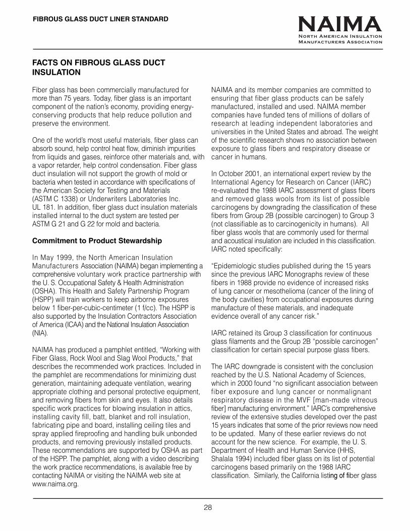
28
FIBROUS GLASS DUCT LINER STANDARD
FACTS ON FIBROUS GLASS DUCTINSULATION
Fiber glass has been commercially manufactured formore than 75 years. Today, fiber glass is an importantcomponent of the nation’s economy, providing energy-conserving products that help reduce pollution andpreserve the environment.
One of the world’s most useful materials, fiber glass canabsorb sound, help control heat flow, diminish impuritiesfrom liquids and gases, reinforce other materials and, witha vapor retarder, help control condensation. Fiber glassduct insulation will not support the growth of mold orbacteria when tested in accordance with specifications ofthe American Society for Testing and Materials(ASTM C 1338) or Underwriters Laboratories Inc.UL 181. In addition, fiber glass duct insulation materialsinstalled internal to the duct system are tested perASTM G 21 and G 22 for mold and bacteria.
Commitment to Product Stewardship
In May 1999, the North American InsulationManufacturers Association (NAIMA) began implementing acomprehensive voluntary work practice partnership withthe U. S. Occupational Safety & Health Administration(OSHA). This Health and Safety Partnership Program(HSPP) will train workers to keep airborne exposuresbelow 1 fiber-per-cubic-centimeter (1 f/cc). The HSPP isalso supported by the Insulation Contractors Associationof America (ICAA) and the National Insulation Association(NIA).
NAIMA has produced a pamphlet entitled, “Working withFiber Glass, Rock Wool and Slag Wool Products,” thatdescribes the recommended work practices. Included inthe pamphlet are recommendations for minimizing dustgeneration, maintaining adequate ventilation, wearingappropriate clothing and personal protective equipment,and removing fibers from skin and eyes. It also detailsspecific work practices for blowing insulation in attics,installing cavity fill, batt, blanket and roll insulation,fabricating pipe and board, installing ceiling tiles andspray applied fireproofing and handling bulk unbondedproducts, and removing previously installed products.These recommendations are supported by OSHA as partof the HSPP. The pamphlet, along with a video describingthe work practice recommendations, is available free bycontacting NAIMA or visiting the NAIMA web site atwww.naima.org.
NAIMA and its member companies are committed toensuring that fiber glass products can be safelymanufactured, installed and used. NAIMA membercompanies have funded tens of millions of dollars ofresearch at leading independent laboratories anduniversities in the United States and abroad. The weightof the scientific research shows no association betweenexposure to glass fibers and respiratory disease orcancer in humans.
In October 2001, an international expert review by theInternational Agency for Research on Cancer (IARC)re-evaluated the 1988 IARC assessment of glass fibersand removed glass wools from its list of possiblecarcinogens by downgrading the classification of thesefibers from Group 2B (possible carcinogen) to Group 3(not classifiable as to carcinogenicity in humans). Allfiber glass wools that are commonly used for thermaland acoustical insulation are included in this classification.IARC noted specifically:
“Epidemiologic studies published during the 15 yearssince the previous IARC Monographs review of thesefibers in 1988 provide no evidence of increased risksof lung cancer or mesothelioma (cancer of the lining ofthe body cavities) from occupational exposures duringmanufacture of these materials, and inadequateevidence overall of any cancer risk.”
IARC retained its Group 3 classification for continuousglass filaments and the Group 2B “possible carcinogen”classification for certain special purpose glass fibers.
The IARC downgrade is consistent with the conclusionreached by the U.S. National Academy of Sciences,which in 2000 found “no significant association betweenfiber exposure and lung cancer or nonmalignantrespiratory disease in the MVF [man-made vitreousfiber] manufacturing environment.” IARC’s comprehensivereview of the extensive studies developed over the past15 years indicates that some of the prior reviews now needto be updated. Many of these earlier reviews do notaccount for the new science. For example, the U. S.Department of Health and Human Service (HHS,Shalala 1994) included fiber glass on its list of potentialcarcinogens based primarily on the 1988 IARCclassification. Similarly, the California listing of fiber glass
NAIMANorth American Insulation
Manufacturers Association
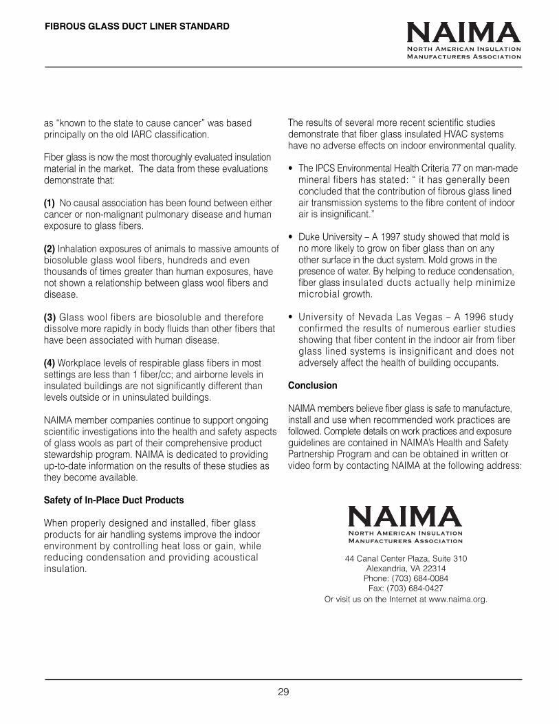
FIBROUS GLASS DUCT LINER STANDARD
29
as “known to the state to cause cancer” was basedprincipally on the old IARC classification.
Fiber glass is now the most thoroughly evaluated insulationmaterial in the market. The data from these evaluationsdemonstrate that:
(1) No causal association has been found between eithercancer or non-malignant pulmonary disease and humanexposure to glass fibers.
(2) Inhalation exposures of animals to massive amounts ofbiosoluble glass wool fibers, hundreds and eventhousands of times greater than human exposures, havenot shown a relationship between glass wool fibers anddisease.
(3) Glass wool fibers are biosoluble and thereforedissolve more rapidly in body fluids than other fibers thathave been associated with human disease.
(4) Workplace levels of respirable glass fibers in mostsettings are less than 1 fiber/cc; and airborne levels ininsulated buildings are not significantly different thanlevels outside or in uninsulated buildings.
NAIMA member companies continue to support ongoingscientific investigations into the health and safety aspectsof glass wools as part of their comprehensive productstewardship program. NAIMA is dedicated to providingup-to-date information on the results of these studies asthey become available.
Safety of In-Place Duct Products
When properly designed and installed, fiber glassproducts for air handling systems improve the indoorenvironment by controlling heat loss or gain, whilereducing condensation and providing acousticalinsulation.
The results of several more recent scientific studiesdemonstrate that fiber glass insulated HVAC systemshave no adverse effects on indoor environmental quality.
• The IPCS Environmental Health Criteria 77 on man-mademineral fibers has stated: “ it has generally beenconcluded that the contribution of fibrous glass linedair transmission systems to the fibre content of indoorair is insignificant.”
• Duke University – A 1997 study showed that mold isno more likely to grow on fiber glass than on anyother surface in the duct system. Mold grows in thepresence of water. By helping to reduce condensation,fiber glass insulated ducts actually help minimizemicrobial growth.
• University of Nevada Las Vegas – A 1996 studyconfirmed the results of numerous earlier studiesshowing that fiber content in the indoor air from fiberglass lined systems is insignificant and does notadversely affect the health of building occupants.
Conclusion
NAIMA members believe fiber glass is safe to manufacture,install and use when recommended work practices arefollowed. Complete details on work practices and exposureguidelines are contained in NAIMA’s Health and SafetyPartnership Program and can be obtained in written orvideo form by contacting NAIMA at the following address:
44 Canal Center Plaza, Suite 310Alexandria, VA 22314
Phone: (703) 684-0084Fax: (703) 684-0427
Or visit us on the Internet at www.naima.org.
NAIMANorth American Insulation
Manufacturers Association
NAIMANorth American Insulation
Manufacturers Association
44 Canal Center Plaza, Suite 310Alexandria, VA 22314Tel: 703-684-0084Fax: 703-684-0427E-mail: [email protected]: http://www.naima.org Pub. # AH124 8/02
DARD
About NAIMA
NAIMA is the association for NorthAmerican manufacturers of fiberglass, rock wool, and slag woolinsulation products. Its role is topromote energy efficiency andenvironmental preservation throughthe use of fiber glass, rock wool,and slag wool insulation, and toencourage the safe productionand use of these materials.
In May 1999, NAIMA beganimplementing a comprehensivevoluntary work practice partnershipwith the U.S. Occupational Safetyand Health Administration (OSHA).The program, known as the Healthand Safety Partnership Program, orHSPP, promotes the safe handlingand use of insulation materials andincorporates education and trainingfor the manufacture, fabrication,installation and removal of fiberglass, rock wool and slag woolinsulation products.
For more information, contact:
For additional information on fibrousglass duct systems, contact one ofthe manufacturers listed below.
CerCerCerCerCertainTtainTtainTtainTtainTeed Corp.eed Corp.eed Corp.eed Corp.eed Corp.P. O. Box 860Valley Forge, PA 19482800-233-8990
Johns ManvilleJohns ManvilleJohns ManvilleJohns ManvilleJohns ManvilleP. O. Box 5108Denver, CO 80217800-654-3103
Knauf InsulationKnauf InsulationKnauf InsulationKnauf InsulationKnauf Insulation1 Knauf DriveShelbyville, IN 46176800-825-4434
Owens CorOwens CorOwens CorOwens CorOwens CorningningningningningOne Owens Corning ParkwayToledo, OH 43659800-GET-PINK
NAIMANorth American Insulation
Manufacturers Association