fiber optic testing - home | lunalunainc.com/wp-content/uploads/2014/05/fiber_optic_t… · ·...
TRANSCRIPT
1
FIBER OPTIC TESTING
2
FIBER OPTIC TEST AND MEASUREMENT SOLUTIONS
We provide diagnostic and test instrumentation for the telecommunications industry, enabling complete characterization of optical components, assemblies, and short-haul networks. Our solutions provide substantial cost and time savings in development, production, and maintenance of next-generation optical network equipment. Our instruments provide the most comprehensive, sensitive and accurate component test available on the market today.
COMPONENT TESTING•Arrayed Waveguide Gratings (AWGs)•Filters•Switches•Wavelength Selective Switches (WSSs)•Reconfigurable Optical Add-Drop Multiplexers (ROADMs)•Couplers•Planar Light-Wave Circuits (PLCs)•Photonic Integrated Circuits (PICs)•Tunable Dispersion Compensation Modules (TDCs)•Fiber Bragg Gratings (FBGs)
NETWORK TESTING•Measure transfer function of entire assembly•Fault location and identification•Data center length verification (skew)
PRODUCTION LINE TESTING•Single instrument, comprehensive, fast measurement•Pass/fail testing•Quality inspection
OTHER TESTING•Design verification/optimization•Quality testing•Accurate system modeling
3
Our test and measurement instruments make it possible for fiber-optic equipment manufacturers to diagnose and test the capabilities of optical components, assemblies, and short-haul networks. Luna’s advanced solutions make it quicker and less costly to develop and produce next-generation optical network equipment that improves communications.
APPLICATIONSThe telecommunications industry relies on Luna to characterize and qualify component or assembly performance as well as to locate and identify flaws in networks and devices. Luna’s equipment can also be used to monitor temperature and strain profiles inside a component or module using the in situ fiber.
Component AnalyzersOur Analyzers utilize swept wavelength interferometry to characterize any single-mode passive optical device yielding insertion loss, polarization dependent loss, optical phase, group delay, chromatic dispersion, and polarization mode dispersion; all as a function of wavelength; in a scan that takes less than 3 seconds.
ReflectometersOur Reflectometers utilize swept wavelength interferometry to provide the industry’s only zero dead-zone, high-resolution reflectometer. Our OBRs allow you to see inside your device or optical path to identify faults, measure individual insertion loss or return loss events, length, skew, group delay, and more.
Tunable LasersOur Phoenix™ C-band swept tunable laser is optimized for linear sweep and high wavelength accuracy. With an integrated wavemeter and two optical detectors, the Phoenix can be used for simple, accurate swept-wavelength measurements.
Optical SwitchesOur optical switches can be integrated with our other test and measurement products to enable scalable testing for multiport devices or manufacturing applications.
TELECOMMUNICATIONS
4
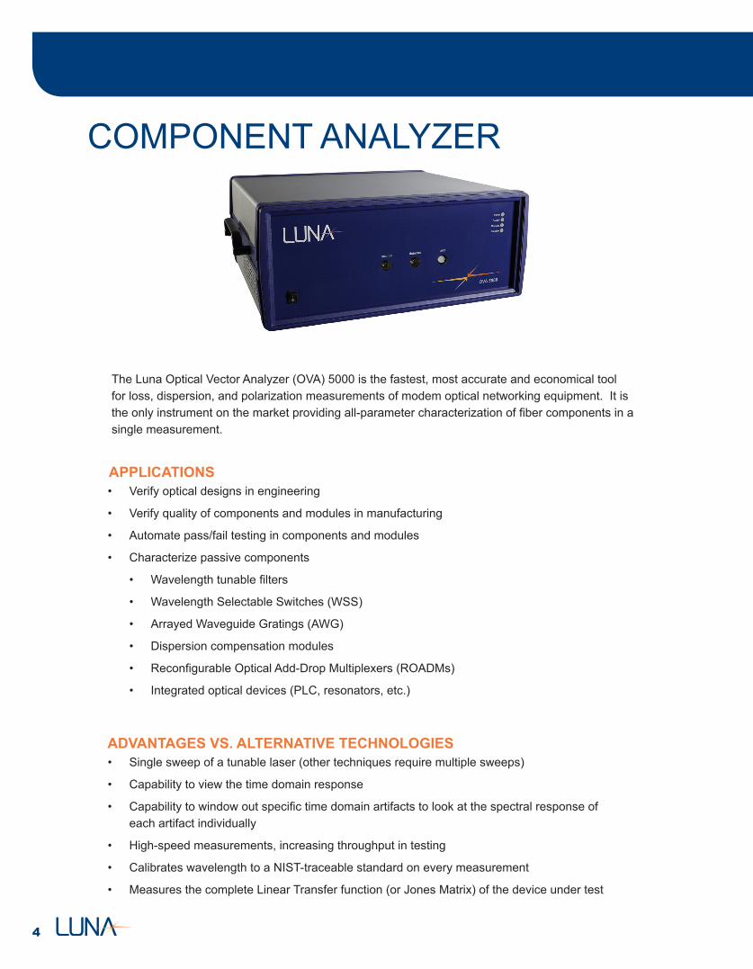
The Luna Optical Vector Analyzer (OVA) 5000 is the fastest, most accurate and economical tool for loss, dispersion, and polarization measurements of modem optical networking equipment. It is the only instrument on the market providing all-parameter characterization of fiber components in a single measurement.
APPLICATIONS• Verify optical designs in engineering
• Verify quality of components and modules in manufacturing
• Automate pass/fail testing in components and modules
• Characterize passive components
• Wavelength tunable filters
• Wavelength Selectable Switches (WSS)
• Arrayed Waveguide Gratings (AWG)
• Dispersion compensation modules
• Reconfigurable Optical Add-Drop Multiplexers (ROADMs)
• Integrated optical devices (PLC, resonators, etc.)
• Single sweep of a tunable laser (other techniques require multiple sweeps)
• Capability to view the time domain response
• Capability to window out specific time domain artifacts to look at the spectral response of each artifact individually
• High-speed measurements, increasing throughput in testing
• Calibrates wavelength to a NIST-traceable standard on every measurement
• Measures the complete Linear Transfer function (or Jones Matrix) of the device under test
ADVANTAGES VS. ALTERNATIVE TECHNOLOGIES
COMPONENT ANALYZER
5
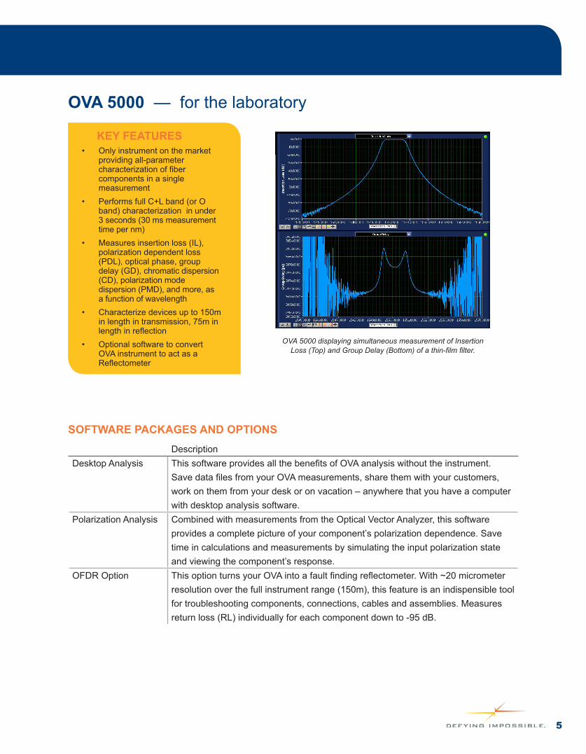
OVA 5000 — for the laboratory
• Only instrument on the market providing all-parameter characterization of fiber components in a single measurement
• Performs full C+L band (or O band) characterization in under 3 seconds (30 ms measurement time per nm)
• Measures insertion loss (IL), polarization dependent loss (PDL), optical phase, group delay (GD), chromatic dispersion (CD), polarization mode dispersion (PMD), and more, as a function of wavelength
• Characterize devices up to 150m in length in transmission, 75m in length in reflection
• Optional software to convert OVA instrument to act as a Reflectometer
KEY FEATURES
OVA 5000 displaying simultaneous measurement of Insertion Loss (Top) and Group Delay (Bottom) of a thin-film filter.
SOFTWARE PACKAGES AND OPTIONSDescription
Desktop Analysis This software provides all the benefits of OVA analysis without the instrument. Save data files from your OVA measurements, share them with your customers, work on them from your desk or on vacation – anywhere that you have a computer with desktop analysis software.
Polarization Analysis Combined with measurements from the Optical Vector Analyzer, this software provides a complete picture of your component’s polarization dependence. Save time in calculations and measurements by simulating the input polarization state and viewing the component’s response.
OFDR Option This option turns your OVA into a fault finding reflectometer. With ~20 micrometer resolution over the full instrument range (150m), this feature is an indispensible tool for troubleshooting components, connections, cables and assemblies. Measures return loss (RL) individually for each component down to -95 dB.
6
APPLICATIONS• Verify quality of optical fiber cable assemblies, connectors, and short-run networks
• Troubleshoot and distinguish between macro-bends, splices, connectors, and breaks
• Verify return - and insertion - loss of multiple points in a fiber assembly or harness simultaneously
• Automate pass/fail verification of fiber assemblies
• Measure strain and temperature in optical components and networks
• Align optics in real time
• High, sub-mm resolution with zero dead-zone
• High sensitivity
• Single connection IL and RL measurements with a single sweep of a tunable laser
• Capability to see the polarization state of the light as it propagates through an optical network
• Ability to use the same instrument for single mode and multimode fiber diagnostics
• Calibrates wavelength to a NIST-traceable standard on every measurement – does not require yearly factory calibration
ADVANTAGES VS. ALTERNATIVE TECHNOLOGIES
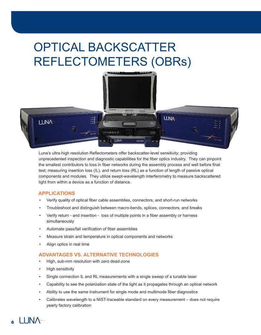
OPTICAL BACKSCATTER REFLECTOMETERS (OBRs)
Luna’s ultra-high resolution Reflectometers offer backscatter-level sensitivity; providing unprecedented inspection and diagnostic capabilities for the fiber optics industry. They can pinpoint the smallest contributors to loss in fiber networks during the assembly process and well before final test; measuring insertion loss (IL), and return loss (RL) as a function of length of passive optical components and modules. They utilize swept-wavelength interferometry to measure backscattered light from within a device as a function of distance.
7
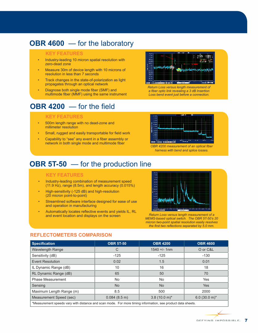
OBR 4600 — for the laboratory
• Industry-leading 10 micron spatial resolution with zero-dead zone
• Measure 30m of device length with 10 microns of resolution in less than 7 seconds
• Track changes in the state-of-polarization as light propagates through an optical network
• Diagnose both single mode fiber (SMF) and multimode fiber (MMF) using the same instrument
KEY FEATURES
OBR 5T-50 — for the production line
• Industry-leading combination of measurement speed (11.9 Hz), range (8.5m), and length accuracy (0.015%)
• High-sensitivity (-125 dB) and high-resolution (20 micron point-to-point)
• Streamlined software interface designed for ease of use and operation in manufacturing
• Automatically locates reflective events and yields IL, RL and event location and displays on the screen
KEY FEATURES
• 500m length range with no dead-zone and millimeter resolution
• Small, rugged and easily transportable for field work• Capability to “see” any event in a fiber assembly or
network in both single mode and multimode fiber
KEY FEATURES
OBR 4200 — for the field
Specification OBR 5T-50 OBR 4200 OBR 4600Wavelength Range C 1540 +/- 1nm O or C&LSensitivity (dB) -125 -125 -130Event Resolution 0.02 1.5 0.01IL Dynamic Range (dB) 10 16 18RL Dynamic Range (dB) 65 50 70Phase Measurement No No YesSensing No No YesMaximum Length Range (m) 8.5 500 2000Measurement Speed (sec) 0.084 (8.5 m) 3.8 (10.0 m)* 6.0 (30.0 m)**Measurement speeds vary with distance and scan mode. For more timing information, see product data sheets.
REFLECTOMETERS COMPARISON
Return Loss versus length measurement of a fiber optic link revealing a 3 dB Insertion Loss bend event just before a connection.
Return Loss versus length measurement of a MEMS-based optical switch. The OBR 5T-50’s 20 micron two-point spatial resolution easily resolves
the first two reflections separated by 5.0 mm.
OBR 4200 measurement of an optical fiber harness with bend and splice losses.
8
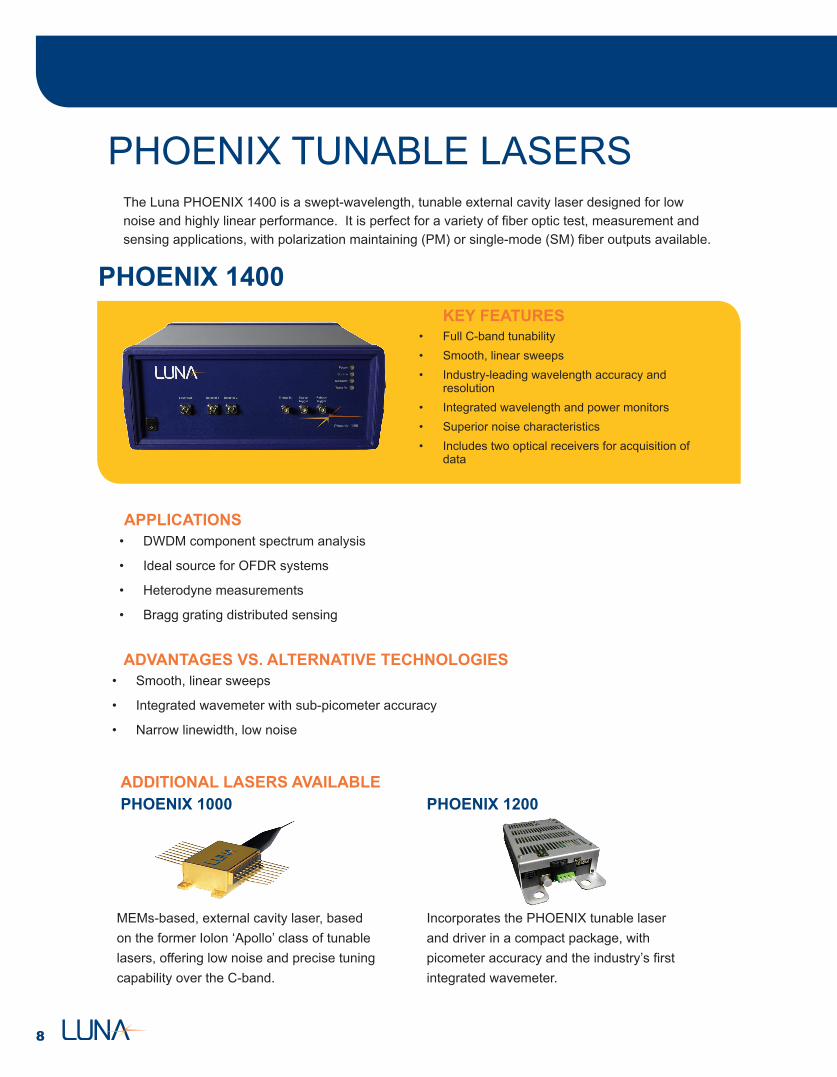
PHOENIX TUNABLE LASERSThe Luna PHOENIX 1400 is a swept-wavelength, tunable external cavity laser designed for low noise and highly linear performance. It is perfect for a variety of fiber optic test, measurement and sensing applications, with polarization maintaining (PM) or single-mode (SM) fiber outputs available.
• Full C-band tunability• Smooth, linear sweeps• Industry-leading wavelength accuracy and
resolution• Integrated wavelength and power monitors• Superior noise characteristics• Includes two optical receivers for acquisition of
data
KEY FEATURES
APPLICATIONS• DWDM component spectrum analysis
• Ideal source for OFDR systems
• Heterodyne measurements
• Bragg grating distributed sensing
• Smooth, linear sweeps
• Integrated wavemeter with sub-picometer accuracy
• Narrow linewidth, low noise
ADVANTAGES VS. ALTERNATIVE TECHNOLOGIES
PHOENIX 1400
PHOENIX 1000
MEMs-based, external cavity laser, based on the former Iolon ‘Apollo’ class of tunable lasers, offering low noise and precise tuning capability over the C-band.
Incorporates the PHOENIX tunable laser and driver in a compact package, with picometer accuracy and the industry’s first integrated wavemeter.
ADDITIONAL LASERS AVAILABLEPHOENIX 1200
9
PUBLICATIONS & WHITE PAPERS• Overview of optical vector network analyzer for single scan measurements of loss, group delay, and
polarization mode dispersion • A white paper describing the Optical Vector Analyzer• May 17, 2005
• Interferometric measurement of dispersion • Introduction to using interferometry to measure dispersion in optical components
• Mark E. Froggatt, Eric Moore, Matthew S. Wolfe
• Linear Systems Approach to Characterizing Components • Introduction to component characterization using linear systems theory
• Mark E. Froggatt, Brian J. Soller, Eric Moore, Matthew S. Wolfe (March 20, 2002)
• Interferometric instrumentation combined with linear systems theory yields BER modeling from component measurement – SPIE magazine • Short introduction to how Optical Vector Analysis can be used to predict component performance
based on eye-diagram and power penalty simulations
• Brian J. Soller (September 2003)
• Optical vector network analyzer for single-scan measurements of loss, group delay, and polarization mode dispersion – Applied Optics magazine
• Overview of method and theory behind the optical vector network analyzer’s ability to complete single-scan measurements of loss, group delay, and polarization mode dispersion
• Dawn K. Gifford, Brian J. Soller, Matthew S. Wolfe, and Mark E. Froggatt (December 2005)
PHOENIX TUNABLE LASERSFiber Optic Component Characterization Dispersion, PMD, Loss, Measurement
• Optical Frequency Domain Reflectometry • Introduction to coherent optical frequency domain reflectometry (C-OFDR)
• Brian J. Soller, Dawn K. Gifford, Matthew S. Wolfe, and Mark E. Froggatt (January 2005)
• Polarization resolved measurement of Rayleigh backscatter in fiber-optic components • Introduction to Optical Backscatter Reflectometry (OBR) with measurement examples
• Brian J. Soller, Matthew S. Wolfe, Mark E. Froggatt (2005)
• Characterization of Polarization-Maintaining Fiber Using High Sensitivity Optical Frequency Domain Reflectometry • A paper by Luna Technologies staff that was published by the Journal of Lightwave Technology.
• Mark E. Froggatt, Dawn K. Gifford, Stephen T. Kreger, Matthew S. Wolfe, and Brian J. Soller (November 2006)
• Return Loss Measurement in the Presence of Variable Insertion Loss Using Optical Frequency Domain Reflectometry • The high spatial resolution and high sensitivity inherent to optical frequency domain reflectometery enables
precise measurements of distributed insertion loss and return loss events
• Stephen T. Kreger, Mark E. Froggatt, Dawn K. Gifford, Matthew S. Wolfe, and Brian J. Soller
• Millimeter Resolution Reflectometry Over Two Kilometers • Millimeter resolution optical frequency domain reflectometry measurements are achieved over 2 km of length.
This level of spatial resolution over kilometer distances enables unprecedented link characterization in emerging short-haul applications such as avionics and FTTx
• Dawn K. Gifford, Mark E. Froggatt, Matthew S. Wolfe, Stephen T. Kreger, Brian J. Soller (September 2007)
• Mode Conditioner and Portable High-Resolution Reflectometer for Maintenance and Diagnostics of Single and Multi-mode Avionic Fiber Networks• Joseph J. Bos, Alex K. Sang, Mark E. Froggatt, Dawn K. Gifford (2011)
Optical Frequency Domain Reflectometry High Resolution OTDR
10
Our technology gives customers the high resolution data they need to design and evaluate complex materials, structures or systems; enabling them to measure strain or temperature like never before: • More cost-effective• Easier to install• More accurate
FIBER OPTIC SENSING
• Identification of delaminations in composite structures
• Non-destructive monitoring, testing and analysis
• Structural load and fatigue testing
• Defect and failure identification and localization
• Load distribution measurement
• Embedded sensing
• Composite cure monitoring
• Early crack detection
• Temperatuare profile mapping
• Instrumenting complex parts easilyCHALLENGE SOLUTION
• Fiber is extremely small and easily installed
• No drift or failure in large strain or high-cycle fatigue testing
• Provides +/- 10,000 microstrain measurement range (1%)
• ≥ 200 sensing points/m of fiber
• Fiber can be routed to map the strain in an area, not just a point
• Performing fatigue testing in composites
• Measurements that work at high strain levels
• Identifying small defects
• Mapping complex strain profiles
KEY FEATURES• 5 mm or better spatial resolution
• Provides ≥ 200 sensing points per meter of fiber with a single connection
• Can measure strain profile vs. time, rather than just strain at a single point vs. time
• Excellent fatigue properties
• System identifies which sensor is connected
• Measurements correlate well with standard techniques
• Meausres strain or temperature
• Enables high density measurements
• Provides hundreds of sensing points per meter
• Can see details foil gages would miss
• Perfect for harsh environments
• Can instrument small and/or complex parts
• Excellent fatigue properties
• Can be surface-bonded or embedded in composites
ADVANTAGES VS. FOIL GAGES
APPLICATIONS
11
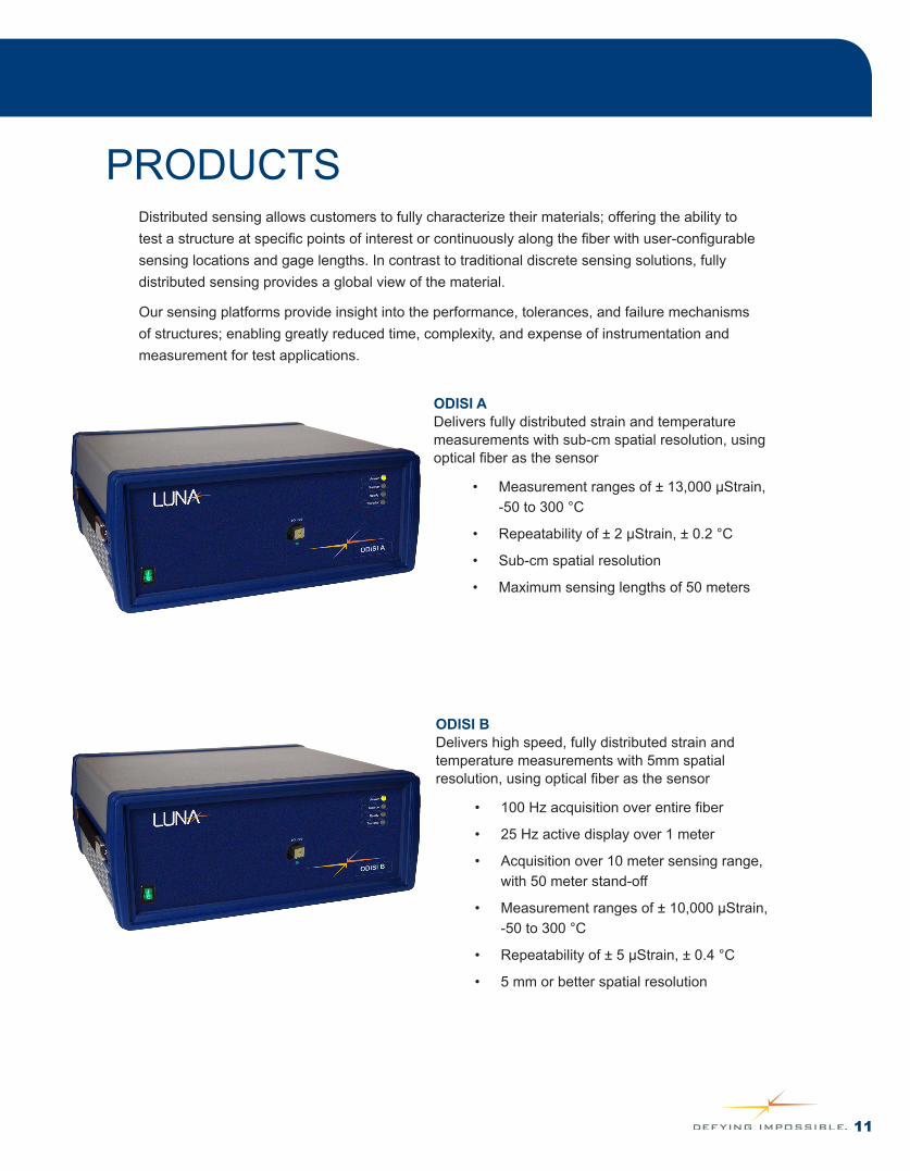
ODISI ADelivers fully distributed strain and temperature measurements with sub-cm spatial resolution, using optical fiber as the sensor
• Measurement ranges of ± 13,000 µStrain, -50 to 300 °C
• Repeatability of ± 2 µStrain, ± 0.2 °C
• Sub-cm spatial resolution
• Maximum sensing lengths of 50 meters
ODISI BDelivers high speed, fully distributed strain and temperature measurements with 5mm spatial resolution, using optical fiber as the sensor
• 100 Hz acquisition over entire fiber
• 25 Hz active display over 1 meter
• Acquisition over 10 meter sensing range, with 50 meter stand-off
• Measurement ranges of ± 10,000 µStrain, -50 to 300 °C
• Repeatability of ± 5 µStrain, ± 0.4 °C
• 5 mm or better spatial resolution
PRODUCTSDistributed sensing allows customers to fully characterize their materials; offering the ability to test a structure at specific points of interest or continuously along the fiber with user-configurable sensing locations and gage lengths. In contrast to traditional discrete sensing solutions, fully distributed sensing provides a global view of the material.
Our sensing platforms provide insight into the performance, tolerances, and failure mechanisms of structures; enabling greatly reduced time, complexity, and expense of instrumentation and measurement for test applications.

12
Every day at Luna we challenge convention.
We are scientists, engineers and business professionals; researching, developing and commercializing innovative technologies for the telecommunications, aerospace, automotive, energy, and defense industries.
Our innovation begins with excellence in research and develops into technologies that can be effectively commercialized. Our products provide all-parameter analysis of optical component and sub-assemblies allowing manufacturers and suppliers to reduce costs and time-to-market by improving component characterization and production schedules.
Our technologies are recognized as leaders in transforming science into solutions:
• Fiber-optic testing instrumentation for telecommunications
• Strain and temperature sensing solutions for composite materials, structures and systems
CONTACT US
www.lunainc.com
ABOUT LUNA
Sales Support: 1.866.586.2682Email: [email protected]
To find a sales contact in your area, please visit our website at www.lunainc.com/sales-map.