fiber curl
DESCRIPTION
fiber curl discriptionTRANSCRIPT
4 April [email protected] Jelle Hogenbirk [email protected]
Fiber integration and manipulation at all stages in Antares
• mechanical specifications of optical fiber
• optical aspects
• mechanical aspects
• fiber handling
• good workman ship
4 April [email protected] Jelle Hogenbirk [email protected]
Fiber integration and manipulation at all stages in Antares
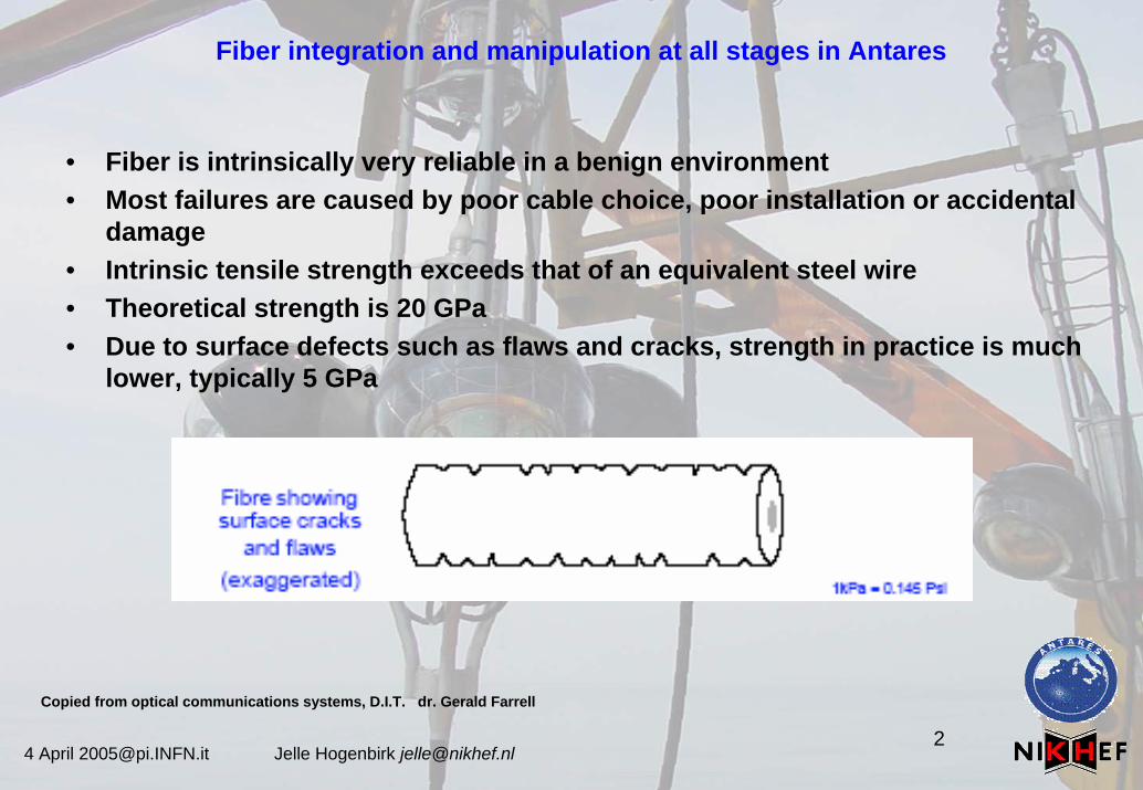
• Fiber is intrinsically very reliable in a benign environment• Most failures are caused by poor cable choice, poor installation or accidental
damage• Intrinsic tensile strength exceeds that of an equivalent steel wire• Theoretical strength is 20 GPa • Due to surface defects such as flaws and cracks, strength in practice is much
lower, typically 5 GPa
Copied from optical communications systems, D.I.T. dr. Gerald Farrell
4 April [email protected] Jelle Hogenbirk [email protected]
Fiber integration and manipulation at all stages in Antares
Mechanical specifications for fiber handling
manufacturer spec’s :tensile proof stress > 100kpsi ~ 0.7 GPa (after ITU spec’s and 0.68kg for SMF-28)
coating strip force Dry: 3 N (~300 gr.) Wet, 14-day @ room temp. 3Nfiber curl > 4.0 m radius curve bending radius macrobend loss tabel (not only optical)
fatigue resistance: Nd 20 (susceptibility parameter)
poor specifications for stress on fiber in relation to time and temperaturecoating strip force?bending radius?weakness or flaws?moister and high temperatures, do they accelerate fiber cracks?silica elastic coefficient less 0.2%
4 April [email protected] Jelle Hogenbirk [email protected]
Fiber integration and manipulation at all stages in Antares
Optical aspects:The need to understand the fiber design parameters for the system.e.g. accurate designs, like dispersion, attenuation, wavelength,polarization mode dispersion, stability, etc. At the end, how to detect a “1” and “0”.
Spec’s influences the parameters negatively, fiber imperfections, splice loss and quality, temperature, mechanical forces applied to the fiber
Use of the fiber imperfections:OTDR based on Rayleigh backscattering (normal OTDR)OTDR based on Brillouin scattering (fiber stress OTDR measurements)
Special made fibers:Fiber-Bragg-Grating for sensor applications, like temperature control, tensile stress measurements, etc
Brillouin scattering: In a physical medium, scattering of lightwaves, caused by thermally driven density fluctuations. Note: Brillouin scattering may cause frequency shifts of several gigahertz at room temperature
graded-index fiber: An optical fiber with a core having a refractive index that decreases with increasing radial distance from the fiber axis. Note: The most common refractive index profile for a graded-index fiber is very nearly parabolic. The parabolic profile results in continual refocusing of the rays in the core, and compensates for multimode distortion.
4 April [email protected] Jelle Hogenbirk [email protected]
Fiber integration and manipulation at all stages in Antares
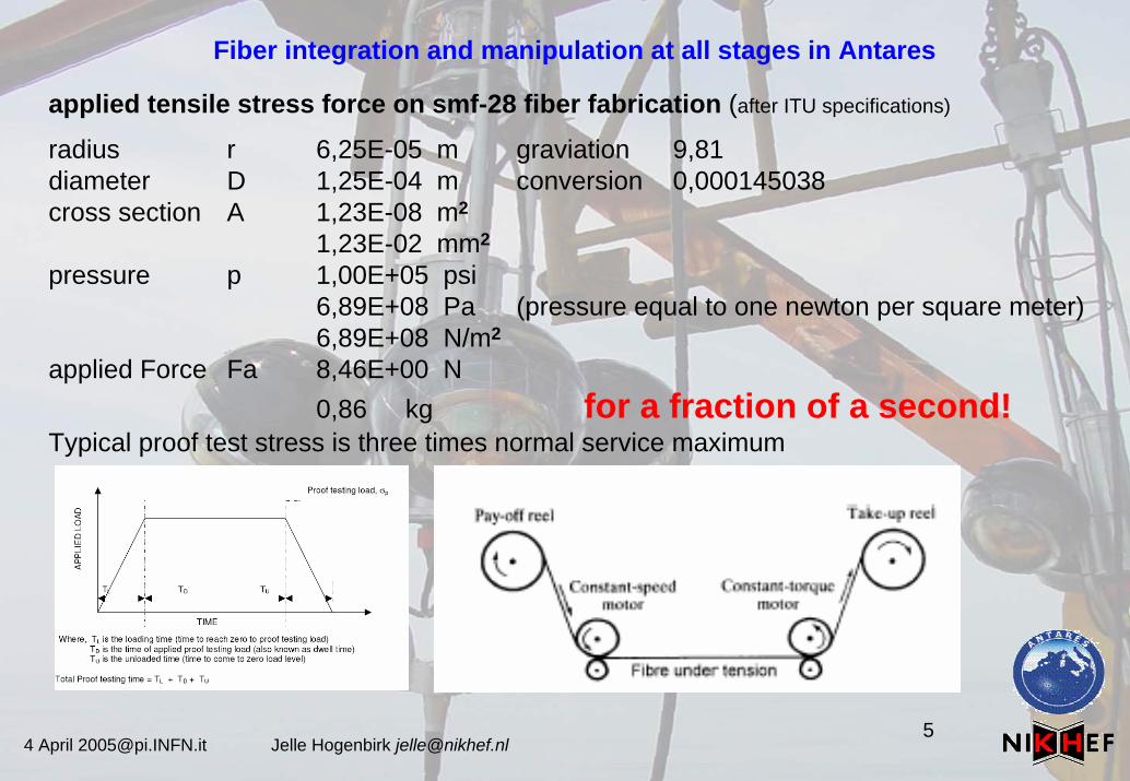
applied tensile stress force on smf-28 fiber fabrication (after ITU specifications)
radius r 6,25E-05 m graviation 9,81diameter D 1,25E-04 m conversion 0,000145038cross section A 1,23E-08 m2
1,23E-02 mm2
pressure p 1,00E+05 psi6,89E+08 Pa (pressure equal to one newton per square meter)6,89E+08 N/m2
applied Force Fa 8,46E+00 N0,86 kg for a fraction of a second!
Typical proof test stress is three times normal service maximum
4 April [email protected] Jelle Hogenbirk [email protected]
Fiber integration and manipulation at all stages in Antares
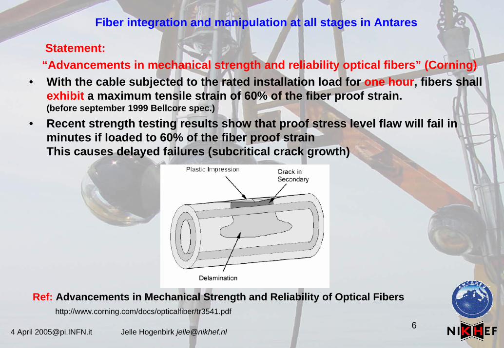
Statement:“Advancements in mechanical strength and reliability optical fibers” (Corning)
• With the cable subjected to the rated installation load for one hour, fibers shall exhibit a maximum tensile strain of 60% of the fiber proof strain. (before september 1999 Bellcore spec.)
• Recent strength testing results show that proof stress level flaw will fail in minutes if loaded to 60% of the fiber proof strainThis causes delayed failures (subcritical crack growth)
Ref: Advancements in Mechanical Strength and Reliability of Optical Fibershttp://www.corning.com/docs/opticalfiber/tr3541.pdf
4 April [email protected] Jelle Hogenbirk [email protected]
Fiber integration and manipulation at all stages in Antares
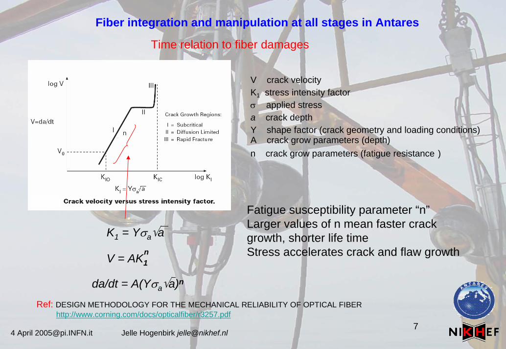
Time relation to fiber damages
Ref: DESIGN METHODOLOGY FOR THE MECHANICAL RELIABILITY OF OPTICAL FIBERhttp://www.corning.com/docs/opticalfiber/r3257.pdf
V crack velocityK1 stress intensity factorσ applied stressa crack depthY shape factor (crack geometry and loading conditions)A crack grow parameters (depth)n crack grow parameters (fatigue resistance )
K1 = Yσa√a
V = AK1n
da/dt = A(Yσa√a)n
Fatigue susceptibility parameter “n”Larger values of n mean faster crack growth, shorter life timeStress accelerates crack and flaw growth
4 April [email protected] Jelle Hogenbirk [email protected]
Fiber integration and manipulation at all stages in Antares
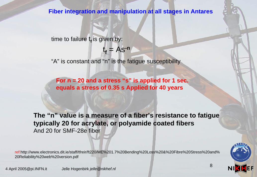
time to failure tf is given by:
“A” is constant and “n” is the fatigue susceptibility
tf = As-n
For n = 20 and a stress “s” is applied for 1 sec.equals a stress of 0.35 s Applied for 40 years
The “n” value is a measure of a fiber’s resistance to fatiguetypically 20 for acrylate, or polyamide coated fibersAnd 20 for SMF-28e fiber
ref:http://www.electronics.dit.ie/staff/tfreir/ft220/ME%201.7%20Bending%20Loss%20&%20Fibre%20Stress%20and% 20Reliability%20web%20version.pdf
4 April [email protected] Jelle Hogenbirk [email protected]
Fiber integration and manipulation at all stages in Antares
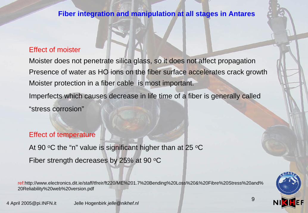
Effect of moisterMoister does not penetrate silica glass, so it does not affect propagationPresence of water as HO ions on the fiber surface accelerates crack growthMoister protection in a fiber cable is most important.
Imperfects which causes decrease in life time of a fiber is generally called
“stress corrosion”
Effect of temperature
At 90 oC the “n” value is significant higher than at 25 oC
Fiber strength decreases by 25% at 90 oC
ref:http://www.electronics.dit.ie/staff/tfreir/ft220/ME%201.7%20Bending%20Loss%20&%20Fibre%20Stress%20and% 20Reliability%20web%20version.pdf
4 April [email protected] Jelle Hogenbirk [email protected]
Fiber integration and manipulation at all stages in Antares
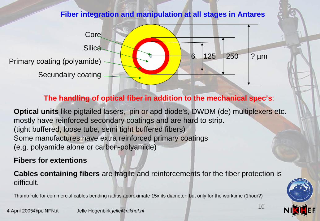
6 125 250 ? µm
Core
Silica
Primary coating (polyamide)
Secundairy coating
The handling of optical fiber in addition to the mechanical spec’s:
Optical units like pigtailed lasers, pin or apd diode's, DWDM (de) multiplexers etc. mostly have reinforced secondary coatings and are hard to strip.(tight buffered, loose tube, semi tight buffered fibers)Some manufactures have extra reinforced primary coatings (e.g. polyamide alone or carbon-polyamide)
Fibers for extentions
Cables containing fibers are fragile and reinforcements for the fiber protection is difficult.
Thumb rule for commercial cables bending radius approximate 15x its diameter, but only for the worktime (1hour?)
4 April [email protected] Jelle Hogenbirk [email protected]
Fiber integration and manipulation at all stages in Antares
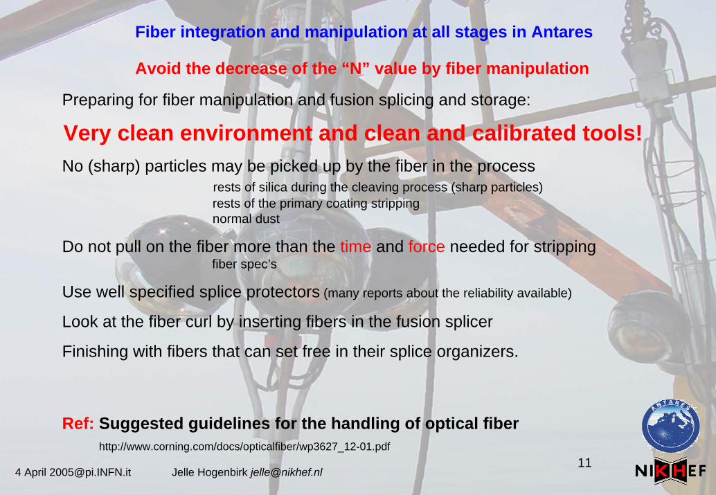
Avoid the decrease of the “N” value by fiber manipulation
Preparing for fiber manipulation and fusion splicing and storage:
Very clean environment and clean and calibrated tools!No (sharp) particles may be picked up by the fiber in the process
rests of silica during the cleaving process (sharp particles)rests of the primary coating strippingnormal dust
Do not pull on the fiber more than the time and force needed for strippingfiber spec’s
Use well specified splice protectors (many reports about the reliability available)
Look at the fiber curl by inserting fibers in the fusion splicer
Finishing with fibers that can set free in their splice organizers.
Ref: Suggested guidelines for the handling of optical fiberhttp://www.corning.com/docs/opticalfiber/wp3627_12-01.pdf
4 April [email protected] Jelle Hogenbirk [email protected]
Fiber integration and manipulation at all stages in Antares
Conclusion: Antares deals all the way trough with a harsh environment.
Many constructive sites where different people with different interestsmanipulate the fibers in difficult circumstances!
•At board level the pigtail extensions and tests.•At the cylinder integration the routing of the fibers.•At the line integration the interconnections.•The deployment
(temperature on deck of the ship to the mechanical stress by launching the line)•The vertical cable (EMC) which is always slowly moving•The “dredge up” of the line (does the line twist a bit? )
It wise to just follow and take it the Corning articles as granted?
Suggested guidelines for the handling of optical fiber http://www.corning.com/docs/opticalfiber/wp3627_12-01.pdf
Setting Splice Specifications for. Single-Mode Fiber Cableshttp://www.corning.com/docs/opticalfiber/wp7114_8-01.pdf
4 April [email protected] Jelle Hogenbirk [email protected]
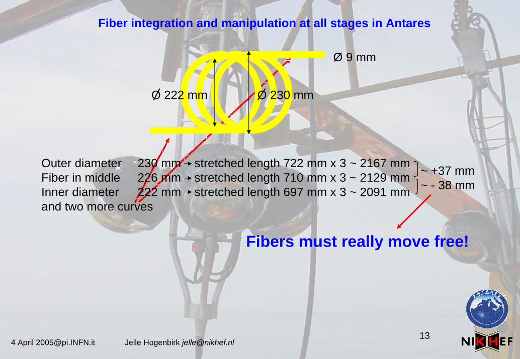
Fiber integration and manipulation at all stages in Antares
O 230 mmO 222 mm
Outer diameter 230 mm stretched length 722 mm x 3 ~ 2167 mmFiber in middle 226 mm stretched length 710 mm x 3 ~ 2129 mm Inner diameter 222 mm stretched length 697 mm x 3 ~ 2091 mmand two more curves
~ +37 mm~ - 38 mm
Ø 9 mm
Fibers must really move free!
4 April [email protected] Jelle Hogenbirk [email protected]
Fiber integration and manipulation at all stages in Antares