fibeairip-10c featuredescription
DESCRIPTION
User ManualTRANSCRIPT
Copyright © 2012 by Ceragon Networks Ltd. All rights reserved.
FibeAir® IP-10C Feature Description
February 2012
Hardware Release: R1
Software Release: C6.9
Document Revision A
FibeAir® IP-10C C6.9 Feature Description
Ceragon Proprietary and Confidential Page 2 of 60
Notice
This document contains information that is proprietary to Ceragon Networks Ltd. No part of this publication may be reproduced, modified, or distributed without prior written authorization of Ceragon Networks Ltd. This document is provided as is, without warranty of any kind.
Registered Trademarks
Ceragon Networks® is a registered trademark of Ceragon Networks Ltd. FibeAir® is a registered trademark of Ceragon Networks Ltd. CeraView® is a registered trademark of Ceragon Networks Ltd. Other names mentioned in this publication are owned by their respective holders.
Trademarks
CeraMap™, ConfigAir™, PolyView™, EncryptAir™, and CeraMon™ are trademarks of Ceragon Networks Ltd. Other names mentioned in this publication are owned by their respective holders.
Statement of Conditions
The information contained in this document is subject to change without notice. Ceragon Networks Ltd. shall not be liable for errors contained herein or for incidental or consequential damage in connection with the furnishing, performance, or use of this document or equipment supplied with it.
Open Source Statement
The Product may use open source software, among them O/S software released under the GPL or GPL alike license ("GPL License"). Inasmuch that such software is being used, it is released under the GPL License, accordingly. Some software might have changed. The complete list of the software being used in this product including their respective license and the aforementioned
public available changes is accessible on http://www.gnu.org/licenses/.
Information to User
Any changes or modifications of equipment not expressly approved by the manufacturer could void the user’s authority to operate the equipment and the warranty for such equipment.
Revision History
Rev Date Author Description Approved by Date
A 26.2.2012 Alex Yufit Initial release. Erez Aviv 28.2.2012
FibeAir® IP-10C C6.9 Feature Description
Ceragon Proprietary and Confidential Page 3 of 60
Table of Contents
Registered Trademarks ......................................................................................... 2
Trademarks ............................................................................................................ 2
Statement of Conditions ........................................................................................ 2
Open Source Statement ........................................................................................ 2
Information to User ................................................................................................ 2
Revision History ..................................................................................................... 2
Table of Contents ................................................................................................... 3
1. Introduction ...................................................................................................... 5
1.1 About this document ...................................................................................................... 5
1.2 IP-10C Hardware Release Introduction ......................................................................... 5
1.3 Version C6.9 Software Release ..................................................................................... 6
1.4 Acronyms ....................................................................................................................... 6
2. General platform support and characteristics ................................................ 8
2.1 Dimensions and voltage rating ....................................................................................... 8
2.2 Front panel interfaces – IP-10C ..................................................................................... 8
2.3 IP-10C Architecture ........................................................................................................ 9 2.3.1 Ethernet Interfaces ......................................................................................................... 9 2.3.2 RF Interface ................................................................................................................. 10 2.3.3 RSL Indication .............................................................................................................. 10 2.3.4 Power Interface ............................................................................................................ 10 2.3.5 Additional Interfaces ..................................................................................................... 11 2.3.6 Cable Connection Options ........................................................................................... 11
2.4 Licensing ...................................................................................................................... 11 2.4.1 General license considerations .................................................................................... 12 2.4.2 License violation ........................................................................................................... 12 2.4.3 Demo (temporary) license ............................................................................................ 12
2.5 Software update timer .................................................................................................. 13
3. Detailed Description of Main Features .......................................................... 14
3.1 Ethernet Traffic Support ............................................................................................... 14 3.1.1 Automatic State Propagation ....................................................................................... 14 3.1.2 Ethernet standard QoS ................................................................................................ 15 3.1.3 Enhanced QoS ............................................................................................................. 20 3.1.4 Ethernet interfaces ....................................................................................................... 33 3.1.5 Ethernet switch applications ........................................................................................ 35 3.1.6 Recommended SFP manufactures .............................................................................. 36 3.1.7 Special and internal VLANs ......................................................................................... 36
3.2 Frequency synchronization support ............................................................................. 37 3.2.1 PRC pipe regenerator mode ........................................................................................ 37
FibeAir® IP-10C C6.9 Feature Description
Ceragon Proprietary and Confidential Page 4 of 60
3.3 Performance Monitoring ............................................................................................... 38 3.3.1 PM measurements ....................................................................................................... 38 3.3.2 Interval behavior when system clock changes ............................................................ 39
3.4 Radio Features ............................................................................................................. 40 3.4.1 ACM ............................................................................................................................. 40 3.4.2 ATPC override timer ..................................................................................................... 43 3.4.3 Alarm on RSL level degradation .................................................................................. 43 3.4.4 Enhanced Multi Layer header compression ................................................................ 44
3.5 Security ........................................................................................................................ 47 3.5.1 User access control ...................................................................................................... 47 3.5.2 Secure communication channels ................................................................................. 47 3.5.3 Security log .................................................................................................................. 51
3.6 System management ................................................................................................... 53 3.6.1 Alarms editing .............................................................................................................. 53 3.6.2 System software interfaces .......................................................................................... 53 3.6.3 Management configuration .......................................................................................... 54 3.6.4 Downloading text CLI configuration scripts .................................................................. 57 3.6.5 Language support ........................................................................................................ 59 3.6.6 NTP .............................................................................................................................. 59
FibeAir® IP-10C C6.9 Feature Description
Ceragon Proprietary and Confidential Page 5 of 60
1. Introduction
This New Software Version (NSV) release introduces the first release of the IP-10C, Ceragon’s compact, all-outdoor backhaul Ethernet product. FibeAir IP-10C combines radio, baseband, and Carrier Ethernet functionality in a single, durable box for outdoor installations.
FibeAir IP-10C offers the convenience of an easy installation procedure, and full compatibility with FibeAir RFU-C mediation devices, enabling easy transition of existing sites to all-outdoor zero-footprint solutions. It is designed for use in tail sites, particularly as part of a Smart Pipe solution.
FibeAir IP-10C covers the entire licensed frequency spectrum and offers a wide capacity range, from 50 Mbps to 1 Gbps over a single radio carrier, depending on traffic scenario based on legacy MAC and enhanced Multi-Layer header compression. Additional functionality and capacity, including Multi-Layer header compression, are enabled via license keys while using the same hardware.
By enabling more capacity, at lower latencies to any location, with proper traffic management mechanisms and an optional downstream boost, FibeAir IP-10C is built to enhance end user Quality of Experience.
FibeAir IP-10C employs the most advanced Adaptive Coding & Modulation (ACM) technique. This unique feature enables users to maximize spectrum utilization and capacity over any given bandwidth and changing environmental conditions.
1.1 About this document
The purpose of this document is to describe the features provided by the IP-10C from a functional point of view. In addition, basic guidelines are provided for certain critical procedures such as software and configuration management.
For detailed configuration instructions,, refer to the following manuals:
FibeAir IP-10C Installation Guide, DOC-00032280
FibeAir IP-10C CeraWeb EMS User Guide, DOC-00033228
FibeAir IP-10C Command Line Interface (CLI) User Guide, DOC-00033229
FibeAir IP-10 License Management System - DOC-00019183
FibeAir CeraBuild Commission Reports Guide, DOC-0002813
1.2 IP-10C Hardware Release Introduction
FibeAir IP-10C features an all outdoor architecture consisting of a single unit directly mounted on the antenna.
RF connection – The IP-10C fits the field-proven direct mount interface, with all available antennas. V and H polarizations are supported using a mechanical twist which should be adjusted to fit the desired configuration.
The mounting bracket allows easy access to installation screws for a simple installation. For details, refer to the IP-10C Installation Guide, DOC-00029988.
FibeAir® IP-10C C6.9 Feature Description
Ceragon Proprietary and Confidential Page 6 of 60
1.3 Version C6.9 Software Release
This release includes new software (referred as version C6.9 in this document) that is meant to run on IP-10C and IP-10Q hardware only. C6.9 is the first software release for the IP-10C product.
Attempting to install this software version in other FibeAir IP-10 products (IP-10G and IP-10E) may make the system inoperative, requiring the hardware to be sent to the manufacturer for replacement.
1.4 Acronyms
AIS Alarm Indication Signal
ACM Adaptive Coding and Modulation
AES Advanced Encryption Standard
BER Bit Error Rate
CA Certificate Authority
DST Daylight Saving Time
EXC BER Excessive BER
FTP (SFTP) File Transfer Protocol (Secured File Transfer Protocol)
GbE / GBE Gigabit Ethernet
GMT Greenwich mean time
IDC InDoor Controller
IFG / IPG Inter Frame/Packet Gap
HTTP (HTTPS) Hypertext Transfer Protocol (Secured HTTP)
LOC Loss Of Carrier
LOF Loss Of Frame
LOS Loss Of Signal
MAC (Ethernet) Media Access Control
MAC (Security) Message Authentication Code
MHC MAC Header Compression
MIB Management Information Base
MSE Minimum Square Error
NTP Network Time Protocol
NSV New Software Version
OAM Operation Administration & Maintenance (Protocols)
PIRL Port Ingress Rate Limiting
PM Performance Monitoring
FibeAir® IP-10C C6.9 Feature Description
Ceragon Proprietary and Confidential Page 7 of 60
PN Provider Network (Port)
PV PolyView
QoS Quality of Service
RSL Received Signal Level
S/N Serial Number
SNMP Simple Network Management Protocol
SNTP Simple Network Time Protocol
SSH Secured Shell (Protocol)
UC User Channel
UTC Universal Time Coordinated
FibeAir® IP-10C C6.9 Feature Description
Ceragon Proprietary and Confidential Page 8 of 60
2. General platform support and characteristics
2.1 Dimensions and voltage rating
This section sets forth basic system specifications.
Dimensions
Height: 355 mm
Width: 220 mm
Depth: 120 mm
DC input voltage nominal rating: -48V
2.2 Front panel interfaces – IP-10C
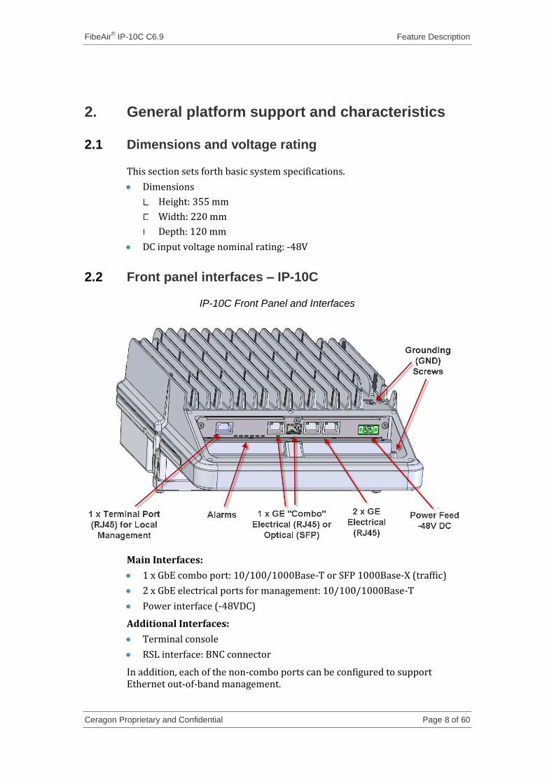
IP-10C Front Panel and Interfaces
Main Interfaces:
1 x GbE combo port: 10/100/1000Base-T or SFP 1000Base-X (traffic)
2 x GbE electrical ports for management: 10/100/1000Base-T
Power interface (-48VDC)
Additional Interfaces:
Terminal console
RSL interface: BNC connector
In addition, each of the non-combo ports can be configured to support Ethernet out-of-band management.
FibeAir® IP-10C C6.9 Feature Description
Ceragon Proprietary and Confidential Page 9 of 60
Front Panel Alarms
LINK – Indicates status of the radio link.
Eth-IF – Indicates status of the Ethernet interface.
RFU – Indicates status of the RF module.
PROT – Reserved for future use.
RMT – Indicates status of the remote unit.
LPWR – Reserved for future use.
Additional LEDs are located next to the Ethernet interfaces. For a description of these LEDs, see Ethernet port LED functionality description on page 34.
2.3 IP-10C Architecture
Featuring an advanced architecture, FibeAir IP-10C uniquely integrates the latest radio technology with Smart Pipe Ethernet capabilities. The FibeAir IP-10C radio core engine is designed to support native Ethernet over the air interface enhanced with Adaptive Power and Adaptive Coding & Modulation (ACM) for maximum spectral efficiency in any deployment scenario.
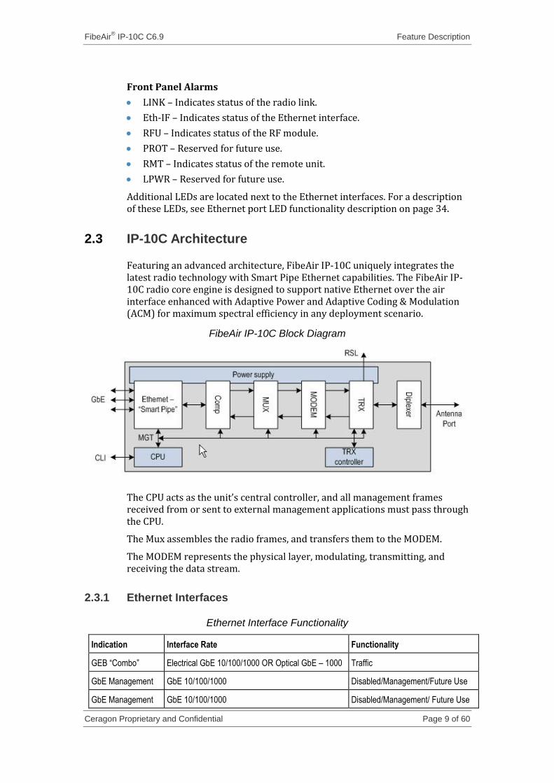
FibeAir IP-10C Block Diagram
The CPU acts as the unit’s central controller, and all management frames received from or sent to external management applications must pass through the CPU.
The Mux assembles the radio frames, and transfers them to the MODEM.
The MODEM represents the physical layer, modulating, transmitting, and receiving the data stream.
2.3.1 Ethernet Interfaces
Ethernet Interface Functionality
Indication Interface Rate Functionality
GEB “Combo” Electrical GbE 10/100/1000 OR Optical GbE – 1000 Traffic
GbE Management GbE 10/100/1000 Disabled/Management/Future Use
GbE Management GbE 10/100/1000 Disabled/Management/ Future Use
FibeAir® IP-10C C6.9 Feature Description
Ceragon Proprietary and Confidential Page 10 of 60
2.3.2 RF Interface
In all configurations, both remote mount and direct mount, IP-10C is connected to the antenna via the RF port. The RF port is a TX/RX direct waveguide connection.
Note: The IP-10C is fully compatible with all RFU-C mediation devices.
For direct mount installations, the following RF interfaces are supported:
Andrew (VHLP), RFS, Xian Putian (WTG), Radio Wave, GD, Shenglu
For remote mount installations, the following RF interfaces are supported:
Frequency (GHz) Waveguide Standard Waveguide Flange
Antenna Flange
6 WR137 PDR70 UDR70
7/8 WR112 PBR84 UBR84
10/11 WR90 PBR100 UBR100
13 WR75 PBR120 UBR120
15 WR62 PBR140 UBR140
18-26 WR42 PBR220 UBR220
28-38 WR28 PBR320 UBR320
If a different antenna type (CPR flange) is used, a flange adaptor is required. Please contact your Ceragon representative for details.
2.3.3 RSL Indication
The RSL indication is used for antenna alignment during the link commissioning phase of installation. Connecting a DVM to this BNC connector will show current RSL in a 3 digit display following the 1V indication.
For example, a level of -35dBm is displayed as 1.35V on the DVM.
Note: The RSL reading is for reference only and is not particularly accurate. For a more accurate RSL indication, use system management to display the RSL value.
2.3.4 Power Interface
The IP-10C power interface is connected via a proprietary two pin connector, at the end of an 18-12AWG cable supplying -48VDC (nominal).
FibeAir® IP-10C C6.9 Feature Description
Ceragon Proprietary and Confidential Page 11 of 60
2.3.5 Additional Interfaces
Craft Terminal – A local craft terminal can be connected to the terminal console for local CLI management.
Grounding Screw – Use the grounding screw for a secure grounding scheme from the IP-10C to the tower.
2.3.6 Cable Connection Options
The IP-10C requires a DC power cable and either an electrical or optical Ethernet cable. Several prepackaged cable options are available:
Bundled Cable Option – – A bundled cable can be ordered that combines a DC power cable and an electrical Ethernet cable in a single unit, with a gland at the top end from which the individual cable ends are separated for connection to the IP-10C unit. The bundled cable can be ordered in lengths of 50m and 75m.
Separate DC and Electrical Ethernet Cables – Ready-made CAT5E cables can be ordered in lengths of 50m and 75m.
Separate DC and Optical Ethernet Cables – Ready-made Single Mode and Multi Mode optical Ethernet cables can be ordered in lengths of 50m, 100m, and 150m.
2.4 Licensing
The following licenses are available for an IP-10C system:
Capacity license: Limits the total amount of radio capacity available. This license is enforced by limiting the bandwidth of the radio script that can be loaded.
ACM license: Enables the use of dynamic ACM radio scripts.
Synchronization unit license: Enables the SyncE PRC regenerator feature.
Enhanced QoS license: Enables the enhanced QoS and PTP optimized transport features.
Enhanced Compression license: Enables Multi-Layer header compression feature.
A particular IP-10C unit can be in one of the following license states:
Default – Factory minimum default license. No License has been purchased or loaded. A Default license is limited to the following capabilities:
Total 10Mbps radio traffic
No ACM
No Synchronization unit license
No enhanced QoS license
No enhanced compression license
IP-10C units are manufactured with a default license installed.
FibeAir® IP-10C C6.9 Feature Description
Ceragon Proprietary and Confidential Page 12 of 60
Normal – Once a license has been successfully loaded to the system, the IP-10C unit is considered to be in a "normal" license state. In a normal license state, access to features and capacities is enabled according to the loaded license key.
Demo – A Demo license is a temporary license that enables access to maximum capacity and all features. This option is limited to 60 days. An event is raised 10 days before expiration. For further details, see Demo (temporary) license on page 12.
2.4.1 General license considerations
A license key is generated per IP-10C serial number (S/N). In order to upgrade a license, the license-key must be entered into the system, followed by a cold reset.
When the system returns online following the reset, its license key is checked, enabling access to new capacities and/or features. If the license key itself is not legal (typing mistake, illegal S/N…), an alarm is raised specific to the problem with the license.
2.4.2 License violation
A License Violation alarm is an alarm scenario in the system, indicating that configuration of the system allows capacities or features that are not allowed by the license.
When a License Violation alarm is raised, radio port capacity is automatically limited to ~3Mbps, allowing only management channels to the remote end. In order to clear the License Violation alarm, the user must configure the system to comply with the loaded license, and then issue a cold-reset. When the system returns online, it checks the legality of the configuration against the license limits. If no violation is detected, no alarm is raised, and the radio is fully operational.
2.4.3 Demo (temporary) license
The user can use a demo (temporary) license that allows the user to activate all features. A demo license is good for 60 days per IP-10C unit, without an option to extend the expiration date. The demo license can be enabled and disabled from the license menu.
When the demo license is disabled or when the 60 days have passed, the system performs a reset and automatically changes the radio script to the last radio script that was used before the demo license was enabled.
While a demo license is enabled, an alarm is raised and a timer on the license menu shows the number of hours remaining on the demo license The timer does not run when the unit is down. 48 hours before the license period is completed, an alarm is raised to notify the user that the demo license will expire within 48 hours.
When the demo license is enabled, all radio scripts are available and the user can choose any script.
FibeAir® IP-10C C6.9 Feature Description
Ceragon Proprietary and Confidential Page 13 of 60
2.5 Software update timer
Users can configure a timer for installation of a software update.
FibeAir® IP-10C C6.9 Feature Description
Ceragon Proprietary and Confidential Page 14 of 60
3. Detailed Description of Main Features
This section includes a review of all features that can be configured in the system.
3.1 Ethernet Traffic Support
3.1.1 Automatic State Propagation
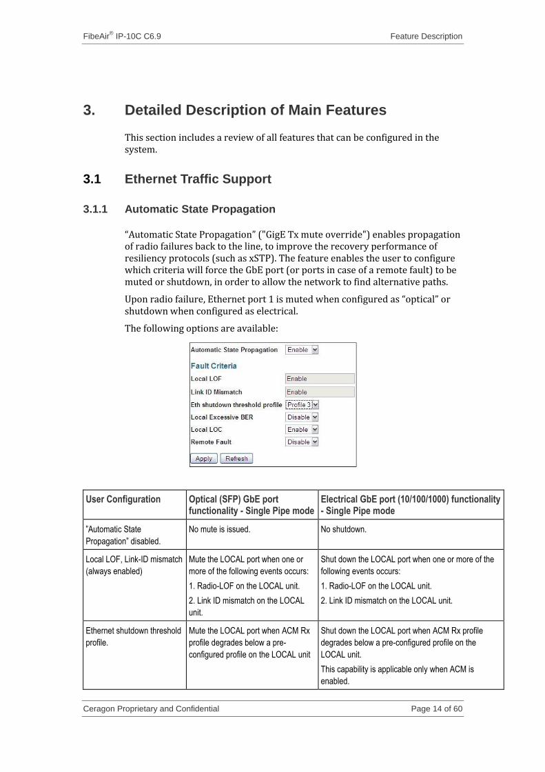
“Automatic State Propagation” ("GigE Tx mute override") enables propagation of radio failures back to the line, to improve the recovery performance of resiliency protocols (such as xSTP). The feature enables the user to configure which criteria will force the GbE port (or ports in case of a remote fault) to be muted or shutdown, in order to allow the network to find alternative paths.
Upon radio failure, Ethernet port 1 is muted when configured as “optical” or shutdown when configured as electrical.
The following options are available:
User Configuration Optical (SFP) GbE port functionality - Single Pipe mode
Electrical GbE port (10/100/1000) functionality - Single Pipe mode
”Automatic State
Propagation” disabled.
No mute is issued. No shutdown.
Local LOF, Link-ID mismatch
(always enabled)
Mute the LOCAL port when one or
more of the following events occurs:
1. Radio-LOF on the LOCAL unit.
2. Link ID mismatch on the LOCAL
unit.
Shut down the LOCAL port when one or more of the
following events occurs:
1. Radio-LOF on the LOCAL unit.
2. Link ID mismatch on the LOCAL unit.
Ethernet shutdown threshold
profile.
Mute the LOCAL port when ACM Rx
profile degrades below a pre-
configured profile on the LOCAL unit
Shut down the LOCAL port when ACM Rx profile
degrades below a pre-configured profile on the
LOCAL unit.
This capability is applicable only when ACM is
enabled.
FibeAir® IP-10C C6.9 Feature Description
Ceragon Proprietary and Confidential Page 15 of 60
User Configuration Optical (SFP) GbE port functionality - Single Pipe mode
Electrical GbE port (10/100/1000) functionality - Single Pipe mode
Local Excessive BER Mute the LOCAL port when an
Excessive BER alarm is raised on the
LOCAL unit
Shut down the LOCAL port when an Excessive BER
alarm is raised on the LOCAL unit
Local LOC Mute the LOCAL port when a GbE-
LOC alarm is raised on the LOCAL
unit.
No shutdown.
Note1: Electrical-GbE cannot be muted. Electrical-
GbE LOC will not trigger Shutdown, because it will not
be possible to enable the port when the LOC alarm is
cleared
Remote Fault Mute the LOCAL port when one or
more of the following events is raised
on the REMOTE unit:
1. Radio-LOF (on remote).
2. Link-ID mismatch (on remote).
3. GbE-LOC alarm is raised (on
remote).
4. ACM Rx profile crossing threshold
(on remote), only if enabled on the
LOCAL.
5. „Excessive BER‟ (on remote), only
if enabled on the LOCAL.
Shut down the LOCAL port, when one or more of the
following events is raised on the REMOTE unit:
1. Radio-LOF (on remote).
2. Link-ID mismatch (on remote).
3. ACM Rx profile crossing threshold (on remote),
only if enabled on the LOCAL.
4. „Excessive BER‟ (on remote), only if enabled on
the LOCAL.
Note1: Electrical-GbE cannot be muted. Electrical-
GbE LOC will not trigger "Shut-down", because it will
not be possible to enable the port when LOC alarm is
cleared
Notes: It is recommended to configure both ends of the link to the same “Automatic State Propagation” configuration.
If the link uses in-band management, when the port is muted or shut down, management distributed through the link might be lost. If this occurs, the unit will not be manageable. The unit will only become manageable again when the port is un-muted or enabled.
3.1.2 Ethernet standard QoS
The QoS feature enables the user to configure classification and scheduling to ensure that packets are forwarded and discarded according to their priority.
Since it is common to set QoS and rate limiting settings identically in several ports, an option has been added to copy the QoS configuration from one port to another. This saves considerable time and prevents configuration mistakes.
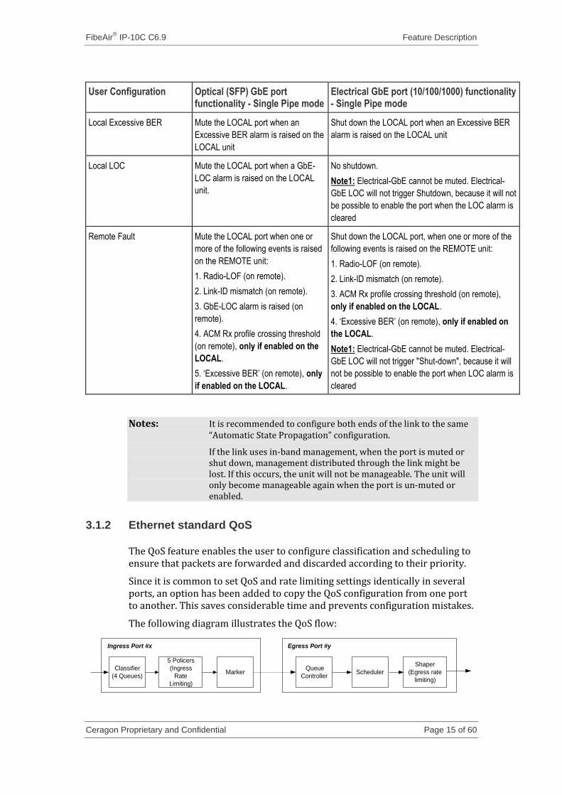
The following diagram illustrates the QoS flow:
Egress Port #yIngress Port #x
Classifier
(4 Queues)
5 Policers
(Ingress
Rate
Limiting)
Queue
Controller
Shaper
(Egress rate
limiting)
Marker Scheduler
FibeAir® IP-10C C6.9 Feature Description
Ceragon Proprietary and Confidential Page 16 of 60
Classifier - Classifies incoming frames to one of four priority queues according to several optional classification criteria. These priority queues are, configured by the user.
3.1.2.1 Classifier criteria
Classifier is made up of four classification criteria hierarchies:
First Criteria: “MAC DA (Destination Address) Overwrite” – Classification and marking is performed for incoming frames carrying a MAC DA that appears in the “Static MAC” table (for details, see Classifier tables on page 17), according to the following options:
Disable – No MAC DA classification or VLAN Pbits overwrite (marking).
Queue Decision – Only classification to queue. No marking.
VLAN Pbits Overwrite – Only VLAN Pbits overwrite (marking). Classification according to a lower criteria.
Queue Decision and VLAN Pbits Overwrite – Both classification and VLAN Pbits overwrite.
Second Criteria: VLAN ID Overwrite –If the first criteria is not fulfilled (either because it is disabled, or because the ingress frame does not carry any MAC DA that appears in the “Status MAC” table), classification and/or marking (VLAN Pbits overwrite, assuming the frame egress is tagged) is decided according to the “VLAN ID to Queue table” (for details, see Classifier tables on page 17) according to the following options:
Disable – No VLAN ID classification or VLAN Pbits overwrite (marking).
Queue Decision – Only classification to queue. No marking.
Third Criteria: VLAN Pbits Overwrite – Only VLAN Pbits overwrite (marking). Classification is according to the lower criteria (pbits or port priority). In this case, Pbits are assigned as follows (if egress frame is tagged):
Frames classified to 1st queue are given Pbits=0
Frames classified to 2nd queue are given Pbits=2
Frames classified to 3rd queue are given Pbits=4
Frames classified to 4th queue are given Pbits=6
Fourth Criteria: Queue Decision & VLAN Pbits Overwrite – Both classification and VLAN Pbits overwrite. Initial Classification is according to the following configuration:
VLAN Pbits – Classification is according to VLAN Pbits. And the queue is assigned according to the “VLAN Pbits to Queue” table (for details, see Classifier tables on page 17).
IP TOS – Classification is according to IP TOS (IP precedence, or IP diffserv). The queue is assigned according to the “IP Pbits to Queue” table (for details, see Classifier tables on page 17).
FibeAir® IP-10C C6.9 Feature Description
Ceragon Proprietary and Confidential Page 17 of 60
VLAN Pbits over IP TOS – Classification according to VLAN Pbits, if the ingress frame carries a VLAN. For untagged packets with an IP header, classification is according to IP TOS.
IP TOS over VLAN Pbits – Classification is according to IP TOS, if the ingress frame has an IP header. If the ingress frame without an IP header carries a VLAN, classification is according to VLAN Pbits.
Port (Default) – If any of the above criteria are not fulfilled, the default classification is assigned to the ingress frame according to the port priority.
Default Classification. Default priority for frames incoming at the port.
3.1.2.2 Classifier tables
The following tables are available to users for configuration:
VLAN-Pbits to Queue – A single table for all ports in the switch. Assigning a queue to a frame, according to the frame’s Pbits (CoS), assuming the frame is tagged.
Each line in the table indicates a different possible value for CoS, with eight table entries (all CoS legal values). The user can define the priority for each value.
IP-Pbits to Queue – A single table for all ports in the switch. Assigning a queue to a frame, according to the frame’s IP priority bits (IP precedence or Diffserv), assuming the frame contains an IP packet. The number of table entries is:
IP Precedence configuration – 8 entries.
DiffServ configuration – 64 entries.
VLAN-ID to Queue – A single table for all ports in the switch. Assigning a queue to a frame, according to the frame’s VLAN-ID. The number of table entries depends on the number of VLANs that have "queue allocation". By default, VLANs do not have pre-determined "queue allocation".
VLAN Pbits priority Remap – A single table per port. Enables the user to remap VLAN-Priority bit values 0-7 to any other preferable value in the range of 0-7. The number of table entries is 8 (all CoS legal values). The remapping table can be used to re-scale some ports’ priorities down (for example 7:0 -> 3:0) while at same time scaling some ports’ priorities up (for example 7:0->7:4), or to ensure that certain priorities are reserved for specific purposes, by initially remapping all frames away from reserved priorities (for example 7:0-> 4:0, protecting priorities 7:5).
Static MAC - A single table for all ports in the switch. This table enables the user to add a “Static MAC” entry to the switch’s forwarding table. Such an entry includes the static MAC address, the ports to which the frame should be forwarded, and a priority, that will be assigned to the frame when “MAC DA classification overwrite” is enabled on the port.
Policer list – A list of all defined policers. Each Policer can have up to five “class map” (policy rule) resources.
FibeAir® IP-10C C6.9 Feature Description
Ceragon Proprietary and Confidential Page 18 of 60
Policer - Port Ingress Rate Limit (BW Profile definitions). Up to five “class maps” can be configured per policer
The system supports a color blind leaky bucket scheme.
Each “class map” has following parameters:
CIR - Committed Information Rate. Rate limiting resolution:
64Kbps <= CIR <= 960Kbps, in steps of 64Kbps.
1000Kbps <= CIR <= 100,000Kbps in steps of 1000Kbps.
100,000Kbps < CIR <= 1,000,000Kbps in steps of 10,000Kbps.
CBS - Committed Burst Size. CBS is CIR-dependent, and should be configured in [bytes]:
For 64Kbps <= CIR <= 960Kbps, 0 < CBS <= 273,404 Bytes.
For 1000Kbps <= CIR <= 100,000Kbps, 0 < CBS <= 132,585 Bytes.
For 100,000Kbps < CIR <= 1,000,000Kbps, 0 < CBS <= 4,192,668 Bytes.
Data type – The rate can be limited based on the following data types:
None (no limiting), Unknown unicast, Unknown multicast, Broadcast, Multicast, Unicast, Management, ARP, TCP-Data, TCP-Control, UDP, Non- UDP, Non-TCP-UDP, Queue1, Queue2, Queue3, Queue4.
Note: Management frames are BPDUs processed by the system’s IDC, when processing L2 protocols (e.g., xSTP).
Limit Exceed Action
Discard Frame.
Note: The rate for rate limiting is measured for all Layer 1 bytes, meaning: Preamble (8bytes) + Frame's DA to CRC + IFG (12 Bytes)
The significance of CIR and CBS is illustrated in the following simple example for a service that provides a CIR=4Mbps (=4,000,000 bps) and a CBS=2KB (=2000 bytes): Two 1518 byte Frames are sent back to back. The first frame depletes 1518 bytes of the initial 2KB CBS in the token bucket leaving 462 bytes remaining (2000 – L1 frame size = 2000 – 1518 – 20 = 462). This service frame is in-profile and delivered per the performance parameters specified by the service. The second 1518 byte Service Frame needs more than the 462 bytes remaining in the bucket and therefore is out-of-profile and is immediately discarded (if the "Limit Exceed Action" configuration is set to "Discard Frame").
3.1.2.3 Ingress rate limiting configuration
In order to configure ingress rate limiting, the user must perform the following steps:
1 From the navigation tree in the Web-Based EMS, select Configuration > Ethernet Switch > QoS & Rate Limiting. The QoS & Rate Limiting window is displayed.
2 From the Advanced section, click Policer List. The Policer List window is displayed.
FibeAir® IP-10C C6.9 Feature Description
Ceragon Proprietary and Confidential Page 19 of 60
3 Click Refresh. The current Policer List settings are displayed. 4 From the Operation drop-down menu, select Add and enter a name with
the new policer. A new line with the selected name is added to the Policer List.
5 Press [+] to expand the line of the new policer. 6 Configure class map by defining CIR, CBS, Data Type, and Limit exceed
action. Parameter limits should be taken from the table at the bottom of the page. Up to five “class maps” can be defined per policer.
Note: The Policer names must not contain spaces.
The class map should have a unique name. Each class map must have a unique name, even if the class maps belong to different policers (CQ18150).
When a policer has been configured, it can be attached to a port:
1 From the navigation tree in the Web-Based EMS, select Configuration > Ethernet Switch > QoS & Rate Limiting.
2 Press [+] to expand the port for rate limiting. 3 Under Ingress rate limit, set the policer name, and click Apply. If the
operation succeeds, the policer is attached to the port.
To detach a policer, click Detach.
Queue Controller - Distributes frames to queues according to the classifier. No related configurations are available to the user.
Scheduler – Determines how frames are output from the queues.
It should be emphasized that the 4th Queue is the Highest Priority Queue, and the 1st Queue is the Lowest Priority Queue.
The following scheduling schemes are supported:
Strict for all queues.
Strict for 4th queue, and HRR for 3rd , 2nd & 1st queues.
Strict for 4th & 3rd queues, and HRR for 2nd & 1st queues.
HRR (Weighted Round Robin) for all queues.
In an HRR scheduling scheme, a weight is assigned to each queue, so that frames egress from the queues according to their assigned weight, in order to avoid starvation of lower priority queues. In addition, frames egress in a mixed manner, in order to avoid bursts of frames from the same queue.
Each queue’s weight can be configured. A queue's weight is used by the scheduler when the specific queue is part of an HRR scheduling scheme. Queue-Weight can be configured in the range of 1-32, and should be configured via the Queues Weights Table. The default queue weights are 8,4,2,1.
Shaper – Determines the scheduler rate (egress rate limit). The following configurations are related to shaper:
Shaper ON/OFF. Shaper is OFF by default.
Shaper Rate. Following rate steps are available:
For 64Kbps <= Rate <= 960Kbps, in steps of 64Kbps.
For 1000Kbps <= Rate <= 100,000Kbps in steps of 1000Kbps.
FibeAir® IP-10C C6.9 Feature Description
Ceragon Proprietary and Confidential Page 20 of 60
For 100,000Kbps < Rate <= 1,000,000Kbps in steps of 10,000Kbps.
3.1.2.4 Additional QoS features
The following multicast addresses are prioritized by classifying them to the highest priority queue (4th Queue):
01:80:C2:00:00:00 (IEEE Std 802.1D Bridge Group Address).
01:80:C2:00:00:02 (IEEE Std 802.3 Slow Protocols Multicast Address).
01:80:C2:00:00:03 (IEEE Std 802.1X PAE address).
01:80:C2:00:00:08 (Provider Bridge group address).
01:80:C2:00:00:0E (Std. 802.1AB Link Layer Discovery Protocol address).
01:00:0C:CC:CC:CD (Cisco PVST)
3.1.3 Enhanced QoS
Enhanced QoS (also called enhanced Traffic Manager), a license-enabled feature, is used to improve the QoS capabilities of the IP-10 platform. Enhanced QoS provides the following improvements:
Enhanced classification criterions.
Improved Scheduler based on strict priorities and/or WFQ algorithm.
8 priority queues with configurable buffer length.
Enhanced shaper per priority queue. Configurable CIR and CBS (based on MEF 10.2 recommendations).
WRED support (see Weighted Random Early Detection (WRED) )
PTP Optimized Transport dedicated channel for time synchronization protocols.
Enhanced PM and statistics.
These enhancements apply to egress traffic on the radio port (where the bottleneck is). All the other ports will function as usual. Enhanced QoS requires a license, and can be enabled and disabled by the user.
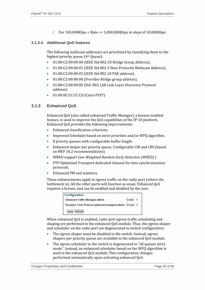
When enhanced QoS is enabled, radio port egress traffic scheduling and shaping are performed in the enhanced QoS module. Thus, the egress shaper and scheduler on the radio port are degenerated in switch configuration:
The egress shaper must be disabled in the switch. Instead, egress shapers per priority queue are available in the enhanced QoS module.
The egress scheduler in the switch is degenerated to ”all queues strict mode”. Instead, an enhanced scheduler based on the WFQ algorithm is used in the enhanced QoS module. This configuration changes performed automatically upon activating enhanced QoS.
FibeAir® IP-10C C6.9 Feature Description
Ceragon Proprietary and Confidential Page 21 of 60
Note: Enabling enhanced QoS will affect the traffic on the radio port.
3.1.3.1 Enhanced QoS classifier
The classifier is a basic element of each QoS mechanism. Each frame is assigned a Class of Service (CoS) and color (based on MEF 10.2 recommendations). The user can define several criteria by which frames will be classified. All the classification criteria are divided into three hierarchies according to their cardinality – from the most specific to the most general.
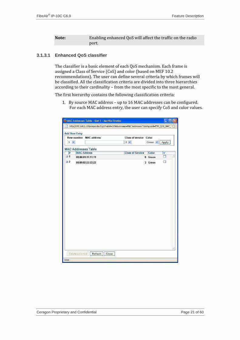
The first hierarchy contains the following classification criteria:
1. By source MAC address – up to 16 MAC addresses can be configured. For each MAC address entry, the user can specify CoS and color values.
FibeAir® IP-10C C6.9 Feature Description
Ceragon Proprietary and Confidential Page 22 of 60
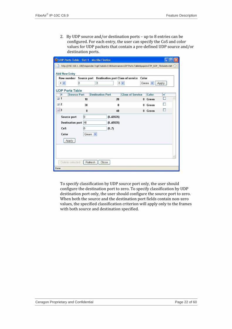
2. By UDP source and/or destination ports – up to 8 entries can be configured. For each entry, the user can specify the CoS and color values for UDP packets that contain a pre-defined UDP source and/or destination ports.
To specify classification by UDP source port only, the user should configure the destination port to zero. To specify classification by UDP destination port only, the user should configure the source port to zero. When both the source and the destination port fields contain non-zero values, the specified classification criterion will apply only to the frames with both source and destination specified.
FibeAir® IP-10C C6.9 Feature Description
Ceragon Proprietary and Confidential Page 23 of 60
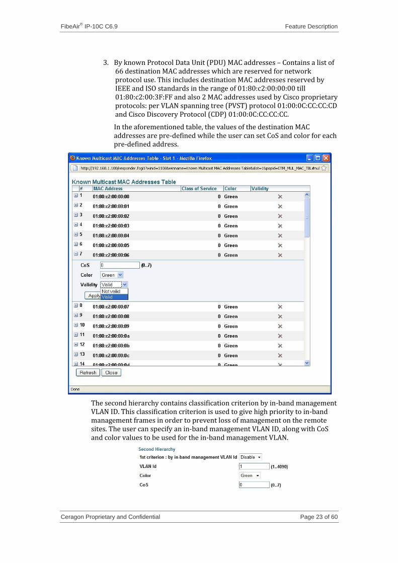
3. By known Protocol Data Unit (PDU) MAC addresses – Contains a list of 66 destination MAC addresses which are reserved for network protocol use. This includes destination MAC addresses reserved by IEEE and ISO standards in the range of 01:80:c2:00:00:00 till 01:80:c2:00:3F:FF and also 2 MAC addresses used by Cisco proprietary protocols: per VLAN spanning tree (PVST) protocol 01:00:0C:CC:CC:CD and Cisco Discovery Protocol (CDP) 01:00:0C:CC:CC:CC.
In the aforementioned table, the values of the destination MAC addresses are pre-defined while the user can set CoS and color for each pre-defined address.
The second hierarchy contains classification criterion by in-band management VLAN ID. This classification criterion is used to give high priority to in-band management frames in order to prevent loss of management on the remote sites. The user can specify an in-band management VLAN ID, along with CoS and color values to be used for the in-band management VLAN.
FibeAir® IP-10C C6.9 Feature Description
Ceragon Proprietary and Confidential Page 24 of 60
WARNING: To prevent loss of management to the remote sites, classification by in-band management must be configured before activating the enhanced QoS feature. Especially at the first activation after upgrade, the in-band management VLAN ID should be assigned CoS 7 and Green color.
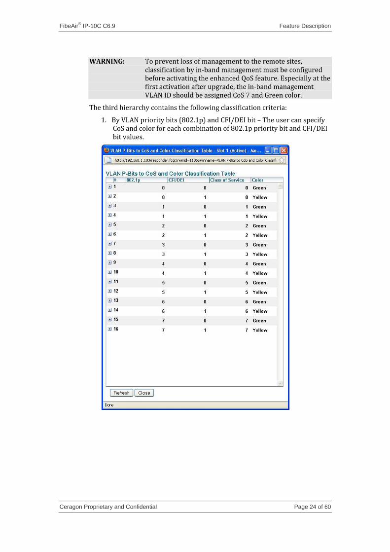
The third hierarchy contains the following classification criteria:
1. By VLAN priority bits (802.1p) and CFI/DEI bit – The user can specify CoS and color for each combination of 802.1p priority bit and CFI/DEI bit values.
FibeAir® IP-10C C6.9 Feature Description
Ceragon Proprietary and Confidential Page 25 of 60
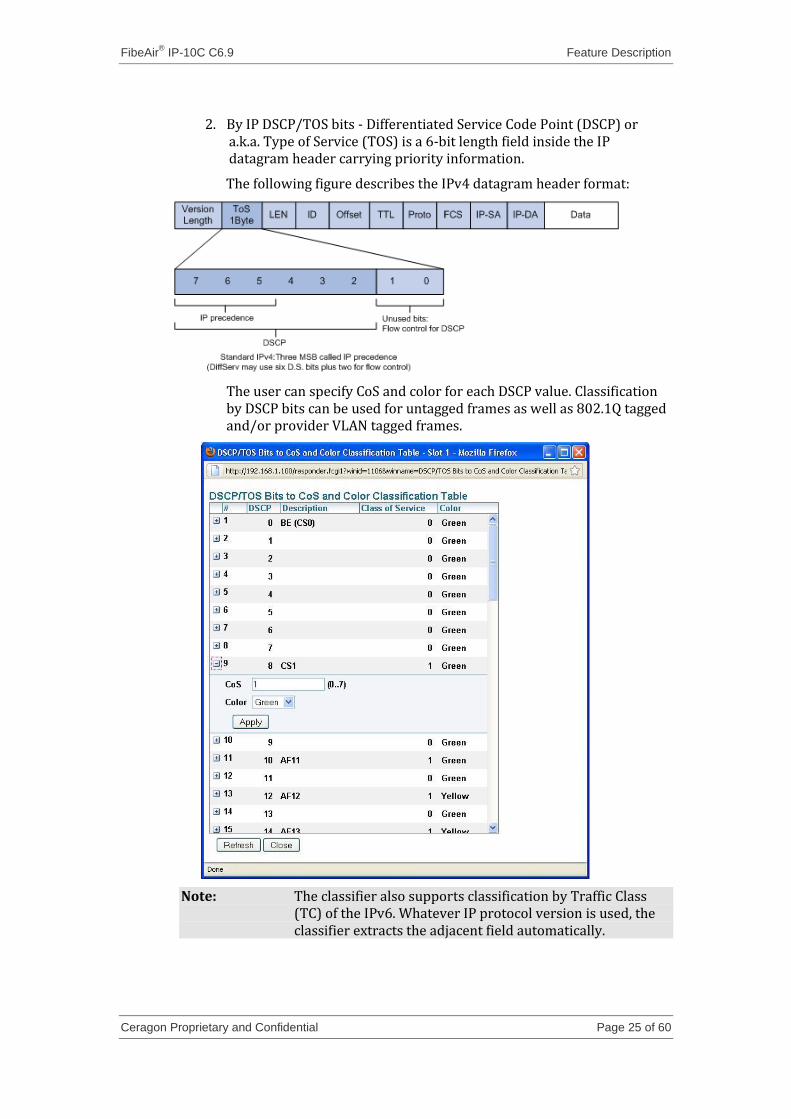
2. By IP DSCP/TOS bits - Differentiated Service Code Point (DSCP) or a.k.a. Type of Service (TOS) is a 6-bit length field inside the IP datagram header carrying priority information.
The following figure describes the IPv4 datagram header format:
The user can specify CoS and color for each DSCP value. Classification by DSCP bits can be used for untagged frames as well as 802.1Q tagged and/or provider VLAN tagged frames.
Note: The classifier also supports classification by Traffic Class (TC) of the IPv6. Whatever IP protocol version is used, the classifier extracts the adjacent field automatically.
FibeAir® IP-10C C6.9 Feature Description
Ceragon Proprietary and Confidential Page 26 of 60
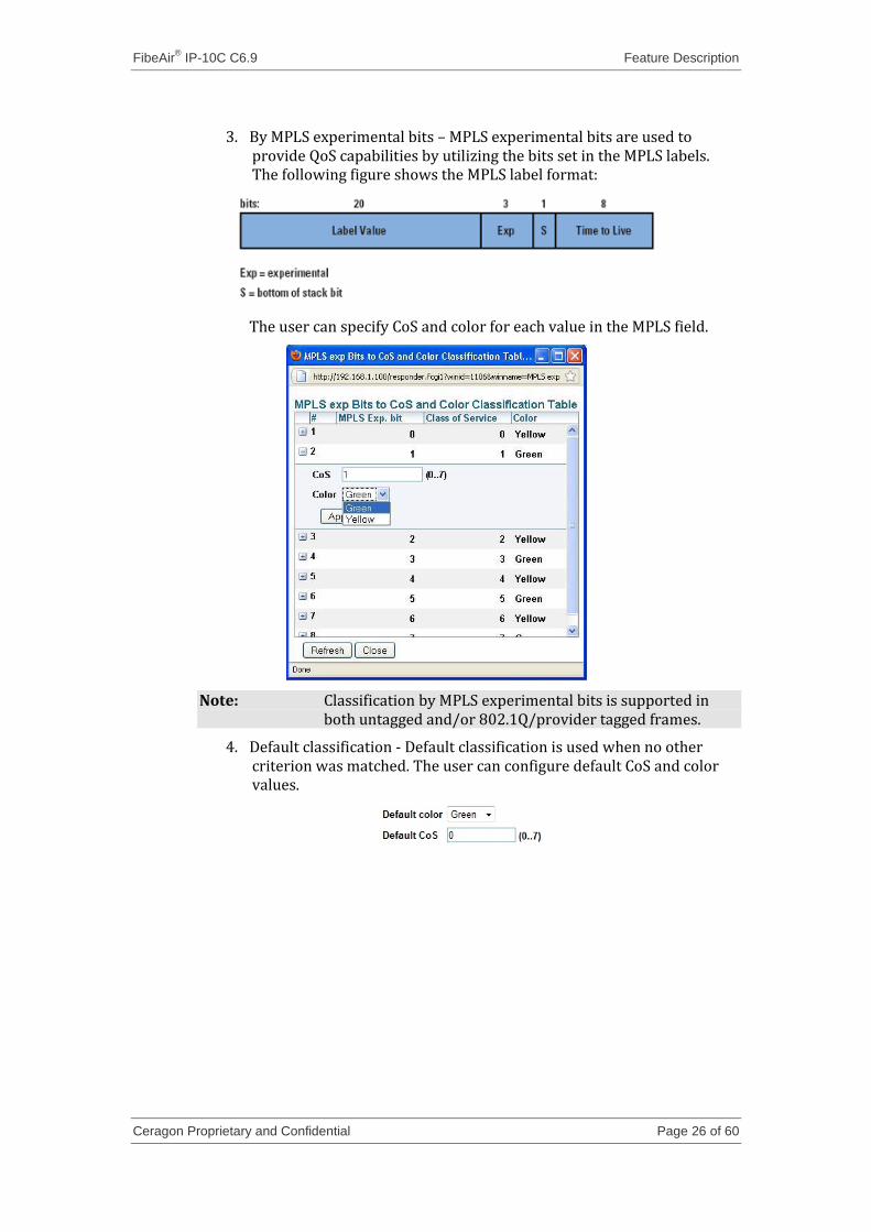
3. By MPLS experimental bits – MPLS experimental bits are used to provide QoS capabilities by utilizing the bits set in the MPLS labels. The following figure shows the MPLS label format:
The user can specify CoS and color for each value in the MPLS field.
Note: Classification by MPLS experimental bits is supported in both untagged and/or 802.1Q/provider tagged frames.
4. Default classification - Default classification is used when no other criterion was matched. The user can configure default CoS and color values.
FibeAir® IP-10C C6.9 Feature Description
Ceragon Proprietary and Confidential Page 27 of 60
3.1.3.2 Class of Service to queue mapping
The user can map dynamically each Class of Service priority queue. Note that each queue is a physical resource which can be assigned accommodate frame of certain (or several) class of service(s).
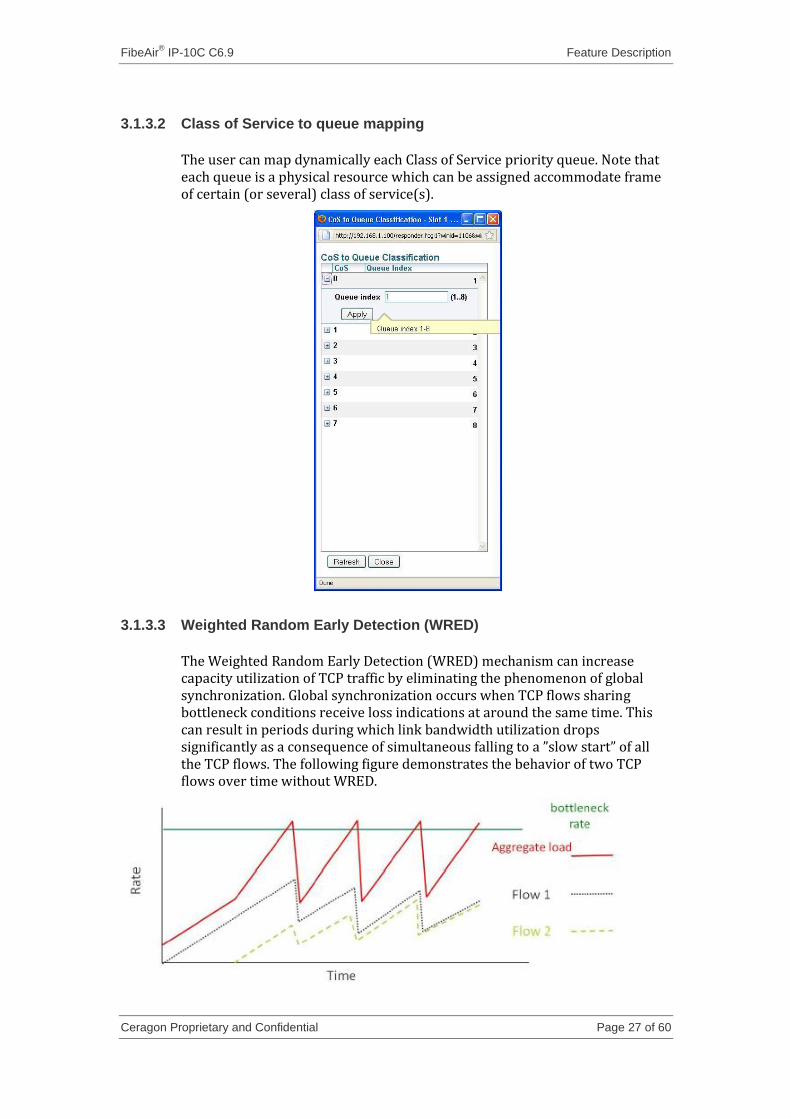
3.1.3.3 Weighted Random Early Detection (WRED)
The Weighted Random Early Detection (WRED) mechanism can increase capacity utilization of TCP traffic by eliminating the phenomenon of global synchronization. Global synchronization occurs when TCP flows sharing bottleneck conditions receive loss indications at around the same time. This can result in periods during which link bandwidth utilization drops significantly as a consequence of simultaneous falling to a ”slow start” of all the TCP flows. The following figure demonstrates the behavior of two TCP flows over time without WRED.
FibeAir® IP-10C C6.9 Feature Description
Ceragon Proprietary and Confidential Page 28 of 60
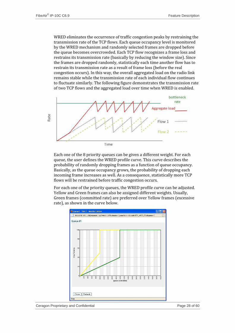
WRED eliminates the occurrence of traffic congestion peaks by restraining the transmission rate of the TCP flows. Each queue occupancy level is monitored by the WRED mechanism and randomly selected frames are dropped before the queue becomes overcrowded. Each TCP flow recognizes a frame loss and restrains its transmission rate (basically by reducing the window size). Since the frames are dropped randomly, statistically each time another flow has to restrain its transmission rate as a result of frame loss (before the real congestion occurs). In this way, the overall aggregated load on the radio link remains stable while the transmission rate of each individual flow continues to fluctuate similarly. The following figure demonstrates the transmission rate of two TCP flows and the aggregated load over time when WRED is enabled.
Each one of the 8 priority queues can be given a different weight. For each queue, the user defines the WRED profile curve. This curve describes the probability of randomly dropping frames as a function of queue occupancy. Basically, as the queue occupancy grows, the probability of dropping each incoming frame increases as well. As a consequence, statistically more TCP flows will be restrained before traffic congestion occurs.
For each one of the priority queues, the WRED profile curve can be adjusted. Yellow and Green frames can also be assigned different weights. Usually, Green frames (committed rate) are preferred over Yellow frames (excessive rate), as shown in the curve below.
FibeAir® IP-10C C6.9 Feature Description
Ceragon Proprietary and Confidential Page 29 of 60
Note: WRED can also be set to a tail drop curve. A tail drop curve is useful for reducing the effective queue size, such as when low latency must be guaranteed. In order to set the tail drop curve to its maximum level, the drop percentage must be set to zero.
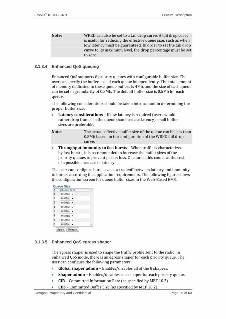
3.1.3.4 Enhanced QoS queuing
Enhanced QoS supports 8 priority queues with configurable buffer size. The user can specify the buffer size of each queue independently. The total amount of memory dedicated to these queue buffers is 4Mb, and the size of each queue can be set in granularity of 0.5Mb. The default buffer size is 0.5Mb for each queue.
The following considerations should be taken into account in determining the proper buffer size:
Latency considerations – If low latency is required (users would rather drop frames in the queue than increase latency) small buffer sizes are preferable.
Note: The actual, effective buffer size of the queue can be less than 0.5Mb based on the configuration of the WRED tail drop curve.
Throughput immunity to fast bursts – When traffic is characterized by fast bursts, it is recommended to increase the buffer sizes of the priority queues to prevent packet loss. Of course, this comes at the cost of a possible increase in latency.
The user can configure burst size as a tradeoff between latency and immunity to bursts, according the application requirements. The following figure shows the configuration screen for queue buffer sizes in the Web-Based EMS.
3.1.3.5 Enhanced QoS egress shaper
The egress shaper is used to shape the traffic profile sent to the radio. In enhanced QoS mode, there is an egress shaper for each priority queue. The user can configure the following parameters:
Global shaper admin – Enables/disables all of the 8 shapers.
Shaper admin – Enables/disables each shaper for each priority queue.
CIR – Committed Information Rate (as specified by MEF 10.2).
CBS – Committed Buffer Size (as specified by MEF 10.2).
FibeAir® IP-10C C6.9 Feature Description
Ceragon Proprietary and Confidential Page 30 of 60
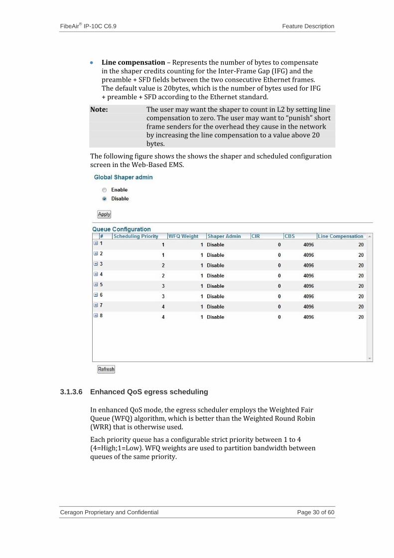
Line compensation – Represents the number of bytes to compensate in the shaper credits counting for the Inter-Frame Gap (IFG) and the preamble + SFD fields between the two consecutive Ethernet frames. The default value is 20bytes, which is the number of bytes used for IFG + preamble + SFD according to the Ethernet standard.
Note: The user may want the shaper to count in L2 by setting line compensation to zero. The user may want to “punish” short frame senders for the overhead they cause in the network by increasing the line compensation to a value above 20 bytes.
The following figure shows the shows the shaper and scheduled configuration screen in the Web-Based EMS.
3.1.3.6 Enhanced QoS egress scheduling
In enhanced QoS mode, the egress scheduler employs the Weighted Fair Queue (WFQ) algorithm, which is better than the Weighted Round Robin (WRR) that is otherwise used.
Each priority queue has a configurable strict priority between 1 to 4 (4=High;1=Low). WFQ weights are used to partition bandwidth between queues of the same priority.
FibeAir® IP-10C C6.9 Feature Description
Ceragon Proprietary and Confidential Page 31 of 60
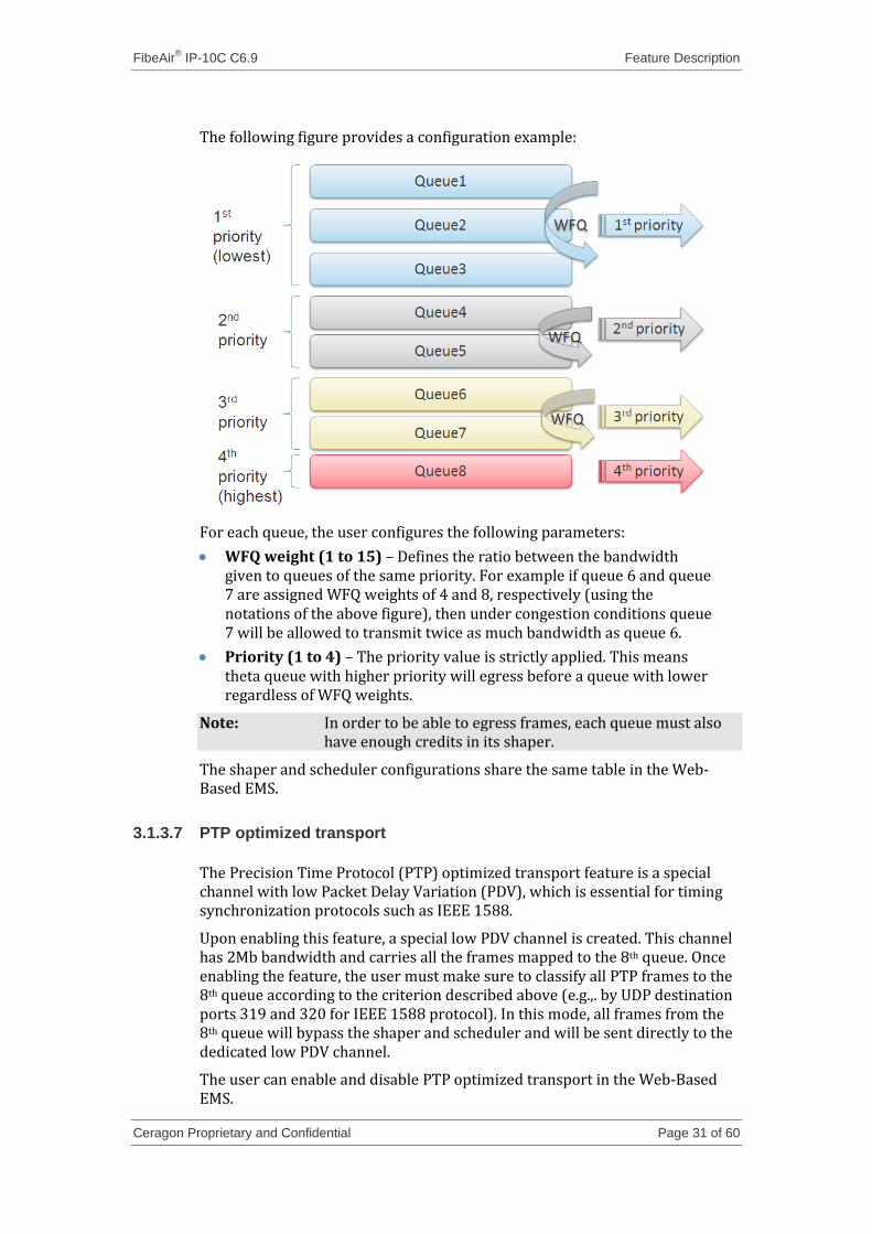
The following figure provides a configuration example:
For each queue, the user configures the following parameters:
WFQ weight (1 to 15) – Defines the ratio between the bandwidth given to queues of the same priority. For example if queue 6 and queue 7 are assigned WFQ weights of 4 and 8, respectively (using the notations of the above figure), then under congestion conditions queue 7 will be allowed to transmit twice as much bandwidth as queue 6.
Priority (1 to 4) – The priority value is strictly applied. This means theta queue with higher priority will egress before a queue with lower regardless of WFQ weights.
Note: In order to be able to egress frames, each queue must also have enough credits in its shaper.
The shaper and scheduler configurations share the same table in the Web-Based EMS.
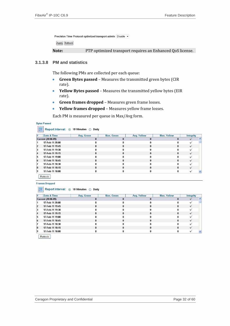
3.1.3.7 PTP optimized transport
The Precision Time Protocol (PTP) optimized transport feature is a special channel with low Packet Delay Variation (PDV), which is essential for timing synchronization protocols such as IEEE 1588.
Upon enabling this feature, a special low PDV channel is created. This channel has 2Mb bandwidth and carries all the frames mapped to the 8th queue. Once enabling the feature, the user must make sure to classify all PTP frames to the 8th queue according to the criterion described above (e.g.,. by UDP destination ports 319 and 320 for IEEE 1588 protocol). In this mode, all frames from the 8th queue will bypass the shaper and scheduler and will be sent directly to the dedicated low PDV channel.
The user can enable and disable PTP optimized transport in the Web-Based EMS.
FibeAir® IP-10C C6.9 Feature Description
Ceragon Proprietary and Confidential Page 32 of 60
Note: PTP optimized transport requires an Enhanced QoS license.
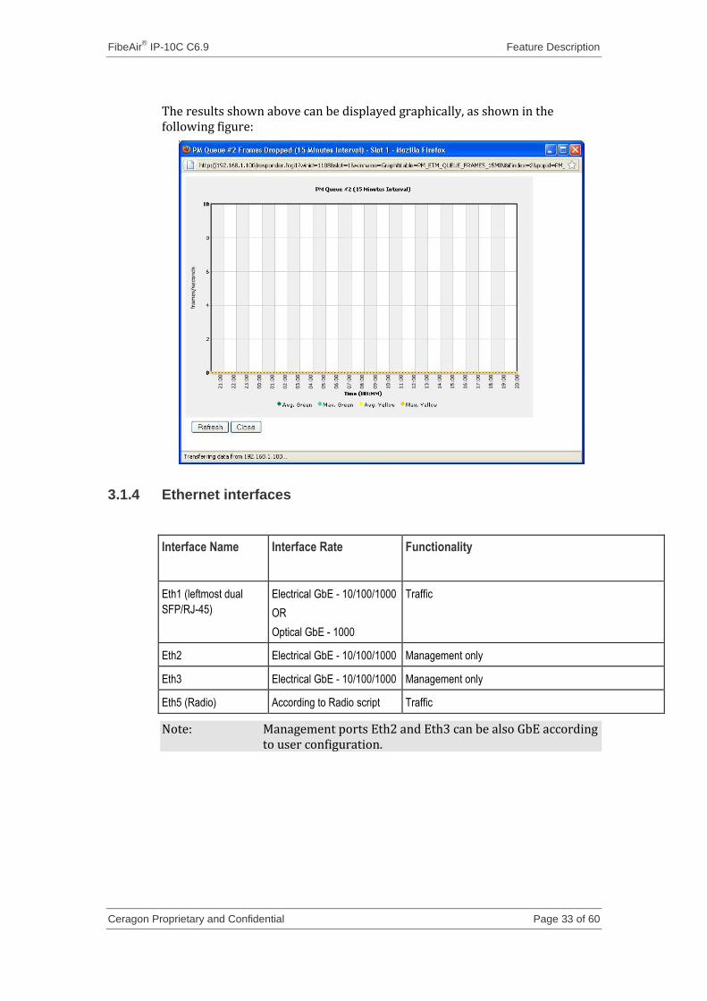
3.1.3.8 PM and statistics
The following PMs are collected per each queue:
Green Bytes passed – Measures the transmitted green bytes (CIR rate).
Yellow Bytes passed – Measures the transmitted yellow bytes (EIR rate).
Green frames dropped – Measures green frame losses.
Yellow frames dropped – Measures yellow frame losses.
Each PM is measured per queue in Max/Avg form.
FibeAir® IP-10C C6.9 Feature Description
Ceragon Proprietary and Confidential Page 33 of 60
The results shown above can be displayed graphically, as shown in the following figure:
3.1.4 Ethernet interfaces
Interface Name Interface Rate Functionality
Eth1 (leftmost dual
SFP/RJ-45)
Electrical GbE - 10/100/1000
OR
Optical GbE - 1000
Traffic
Eth2 Electrical GbE - 10/100/1000 Management only
Eth3 Electrical GbE - 10/100/1000 Management only
Eth5 (Radio) According to Radio script Traffic
Note: Management ports Eth2 and Eth3 can be also GbE according to user configuration.
FibeAir® IP-10C C6.9 Feature Description
Ceragon Proprietary and Confidential Page 34 of 60
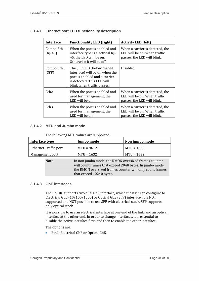
3.1.4.1 Ethernet port LED functionality description
Interface Functionality LED (right) Activity LED (left)
Combo Eth1 (RJ-45)
When the port is enabled and interface type is electrical RJ-45, the LED will be on. Otherwise it will be off.
When a carrier is detected, the LED will be on. When traffic passes, the LED will blink.
Combo Eth1 (SFP)
The SFP LED (below the SFP interface) will be on when the port is enabled and a carrier is detected. This LED will blink when traffic passes.
Disabled
Eth2 When the port is enabled and used for management, the LED will be on.
When a carrier is detected, the LED will be on. When traffic passes, the LED will blink.
Eth3 When the port is enabled and used for management, the LED will be on.
When a carrier is detected, the LED will be on. When traffic passes, the LED will blink.
3.1.4.2 MTU and Jumbo mode
The following MTU values are supported:
Interface type Jumbo mode Non jumbo mode
Ethernet Traffic port MTU = 9612 MTU = 1632
Management port MTU = 1632 MTU = 1632
Note: In non jumbo mode, the RMON oversized frames counter will count frames that exceed 2048 bytes. In jumbo mode, the RMON oversized frames counter will only count frames that exceed 10240 bytes.
3.1.4.3 GbE interfaces
The IP-10C supports two dual GbE interface, which the user can configure to Electrical GbE (10/100/1000) or Optical GbE (SFP) interface. It is NOT supported and NOT possible to use SFP with electrical stack. SFP supports only optical stack.
It is possible to use an electrical interface at one end of the link, and an optical interface at the other end. In order to change interfaces, it is essential to disable the active interface first, and then to enable the other interface.
The options are:
Eth1: Electrical GbE or Optical GbE.
FibeAir® IP-10C C6.9 Feature Description
Ceragon Proprietary and Confidential Page 35 of 60
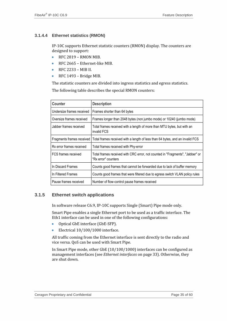
3.1.4.4 Ethernet statistics (RMON)
IP-10C supports Ethernet statistic counters (RMON) display. The counters are designed to support:
RFC 2819 – RMON MIB.
RFC 2665 – Ethernet-like MIB.
RFC 2233 – MIB II.
RFC 1493 – Bridge MIB.
The statistic counters are divided into ingress statistics and egress statistics.
The following table describes the special RMON counters:
Counter Description
Undersize frames received Frames shorter than 64 bytes
Oversize frames received Frames longer than 2048 bytes (non jumbo mode) or 10240 (jumbo mode)
Jabber frames received Total frames received with a length of more than MTU bytes, but with an
invalid FCS
Fragments frames received Total frames received with a length of less than 64 bytes, and an invalid FCS
Rx error frames received Total frames received with Phy-error
FCS frames received Total frames received with CRC error, not counted in "Fragments", "Jabber" or
"Rx error" counters
In Discard Frames Counts good frames that cannot be forwarded due to lack of buffer memory
In Filtered Frames Counts good frames that were filtered due to egress switch VLAN policy rules
Pause frames received Number of flow-control pause frames received
3.1.5 Ethernet switch applications
In software release C6.9, IP-10C supports Single (Smart) Pipe mode only.
Smart Pipe enables a single Ethernet port to be used as a traffic interface. The Eth1 interface can be used in one of the following configurations:
Optical GbE interface (GbE-SFP).
Electrical 10/100/1000 interface.
All traffic coming from the Ethernet interface is sent directly to the radio and vice versa. QoS can be used with Smart Pipe.
In Smart Pipe mode, other GbE (10/100/1000) interfaces can be configured as management interfaces (see Ethernet interfaces on page 33). Otherwise, they are shut down.
FibeAir® IP-10C C6.9 Feature Description
Ceragon Proprietary and Confidential Page 36 of 60
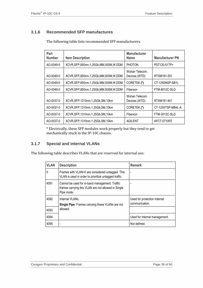
3.1.6 Recommended SFP manufactures
The following table lists recommended SFP manufacturers.
Part Number Item Description
Manufacturer Name Manufacturer PN
AO-0049-0 XCVR,SFP,850nm,1.25Gb,MM,500M,W.DDM PHOTON PST120-51TP+
AO-0049-0 XCVR,SFP,850nm,1.25Gb,MM,500M,W.DDM
Wuhan Telecom.
Devices (WTD) RTXM191-551
AO-0049-0 XCVR,SFP,850nm,1.25Gb,MM,500M,W.DDM CORETEK (*) CT-1250NSP-SB1L
AO-0049-0 XCVR,SFP,850nm,1.25Gb,MM,500M,W.DDM Fiberxon FTM-8012C-SLG
AO-0037-0 XCVR,SFP,1310nm,1.25Gb,SM,10km
Wuhan Telecom.
Devices (WTD) RTXM191-401
AO-0037-0 XCVR,SFP,1310nm,1.25Gb,SM,10km CORETEK (*) CT-1250TSP-MB4L-A
AO-0037-0 XCVR,SFP,1310nm,1.25Gb,SM,10km Fiberxon FTM-3012C-SLG
AO-0037-0 XCVR,SFP,1310nm,1.25Gb,SM,10km AGILENT AFCT-5710PZ
* Electrically, these SFP modules work properly but they tend to get mechanically stuck in the IP-10C chassis.
3.1.7 Special and internal VLANs
The following table describes VLANs that are reserved for internal use:
VLAN Description Remark
0 Frames with VLAN=0 are considered untagged. This
VLAN is used in order to prioritize untagged traffic
-
4091 Cannot be used for in-band management. Traffic
frames carrying this VLAN are not allowed in Single
Pipe mode.
-
4092 Internal VLANs.
Single Pipe: Frames carrying these VLANs are not
allowed.
Used for protection internal
communication.
4093
4094 Used for internal management.
4095 - Not defined.
FibeAir® IP-10C C6.9 Feature Description
Ceragon Proprietary and Confidential Page 37 of 60
3.2 Frequency synchronization support
3.2.1 PRC pipe regenerator mode
PRC pipe regenerator mode is available in IP-10C systems. In this mode, frequency is transported between the GbE interfaces through the radio link.
PRC pipe regenerator mode makes use of the fact that the system is acting as a simple link (so no distribution mechanism is necessary) in order to achieve the following:
Improved frequency distribution performance:
PRC quality
No use of bandwidth for frequency distribution
Simplified configuration
3.2.1.1 Basic operation
In PRC pipe regenerator mode, frequency is taken from the incoming GbE Ethernet signal, and used as a reference for the radio frame. On the receiver side, the radio frame frequency is used as the reference signal for the outgoing Ethernet PHY.
Frequency distribution behaves in a different way for optical and electrical GbE interfaces, because of the way these interfaces are implemented:
For optical interface, separate and independent frequencies are transported in each direction.
For electrical interfaces, each PHY must act either as clock master or as clock slave in its own link. For this reason, frequency can only be distributed in one direction, determined by the user.
3.2.1.2 User configuration
For PRC pipe regenerator mode to work, the following is necessary:
Ethernet port #1 (GbE) must be enabled.
Ethernet interfaces must not be configured as the system synchronization source.
User can configure the following:
PRC regenerator mode admin
Direction of synchronization distribution (applicable only for electrical GbE interfaces; for optical interfaces, this parameter is ignored)
Line to radio
Radio to line
3.2.1.3 Licensing
PRC regenerator is a licensed feature. It requires a “SyncU” license. Enabling PRC regenerator without the proper license will cause a license violation alarm.
FibeAir® IP-10C C6.9 Feature Description
Ceragon Proprietary and Confidential Page 38 of 60
3.3 Performance Monitoring
3.3.1 PM measurements
The following PMs are measured (15 minute or 24 hour intervals):
Radio PMs
MSE PM:
Minimum MSE
Maximum MSE
Exceed MSE Threshold seconds
Radio MRMC
Minimum ACM profile
Maximum ACM profile
Minimum Bit-rate (Mbps)
Maximum Bit-rate (Mbps)
Radio Ethernet frame error rate
Frame error rate (%) measured on radio-Ethernet interface
Radio Ethernet Throughput (rate of data bits rate measured on radio-Ethernet interface)
Peak throughput.
Average throughput
Exceed throughput threshold seconds
Radio Ethernet Capacity (overall Ethernet bits rate, data and overhead, measured on radio-Ethernet interface):
Peak Capacity
Average Capacity
Exceed Capacity threshold seconds.
Note: Ethernet throughput and capacity PMs are measured by accumulating the number of Ethernet octets every second, as they are counted by the RMON counters. Injecting constant data into the unit, trying to test whether these PMs give constant value, shows that the values are not constant as they were expected to be, but have a very low “ripple”. This ripple is negligible, and does not affect the reliability of the PM measurement (CQ17918).
Radio Ethernet Utilization (Actual Ethernet throughput, relative to the potential Ethernet throughput of the radio). Utilization (%) is displayed as one of five bins: 0-20%, 20-40%, 40-60%, 60-80%, 80-100%):
Peak Utilization
Average Utilization
Exceed Utilization threshold seconds
FibeAir® IP-10C C6.9 Feature Description
Ceragon Proprietary and Confidential Page 39 of 60
3.3.2 Interval behavior when system clock changes
The PM intervals may be changed due to a system clock change (because of NTP updates or user configuration). The criteria for change are the following:
The current interval is marked as IDF if the time changes more than 30 seconds.
A new interval is added if the time changes by more than 30 seconds or the new time crosses the interval boundary, and the time left to the end of the interval grows.
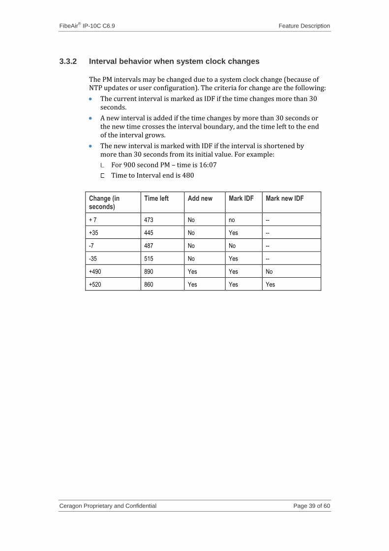
The new interval is marked with IDF if the interval is shortened by more than 30 seconds from its initial value. For example:
For 900 second PM – time is 16:07
Time to Interval end is 480
Change (in seconds)
Time left Add new Mark IDF Mark new IDF
+ 7 473 No no --
+35 445 No Yes --
-7 487 No No --
-35 515 No Yes --
+490 890 Yes Yes No
+520 860 Yes Yes Yes
FibeAir® IP-10C C6.9 Feature Description
Ceragon Proprietary and Confidential Page 40 of 60
3.4 Radio Features
3.4.1 ACM
3.4.1.1 General overview
“Adaptive Coding and Modulation” (ACM) radio capability is supported by the following radio scripts:
ACM-56MHz, QPSK – 256QAM
ACM-50MHz, QPSK – 256QAM
ACM-40MHz, QPSK – 256QAM
ACM-30MHz, QPSK – 256QAM
ACM-28MHz, QPSK – 256QAM
An ACM radio script is constructed of a set of profiles. Each profile is defined by a modulation order (QAM) and coding rate, which dictates the profile’s capacity (in bps). When an ACM script is activated, the system automatically chooses which profile to use according to the channel fading conditions.
The ACM TX profile can be different from the ACM RX profile.
The ACM TX profile is determined by remote RX MSE performance. The RX end initiates an ACM profile upgrade or downgrade. When MSE improves above a predefined threshold, RX generates a request to the remote TX to upgrade its profile. If MSE degrades below a predefined threshold, RX generates a request to the remote TX to downgrade its profile.
ACM profiles are decreased or increased in an errorless operation, without affecting the Ethernet traffic.
ACM scripts can be activated in one of two modes:
Fixed Mode. In this mode, the user selects the specific profile from all available profiles in the script. The selected profile is the only profile that will be valid, and the ACM engine will be forced to be OFF. This mode can be chosen without an ACM license.
Adaptive Mode. In this mode, the ACM engine runs, which means that the radio adapts its profile according to the channel fading conditions. When this mode is used, a maximum profile should be selected by the user, which limits the highest profile that can be used. For example, if the user selects a maximum profile of 5, the system will not climb above the profile 5, even if channel fading conditions allow it. The user can also configure a minimum profile (see Minimum ACM profile on page 42). Adaptive mode requires a valid ACM license.
FibeAir® IP-10C C6.9 Feature Description
Ceragon Proprietary and Confidential Page 41 of 60
3.4.1.2 Adaptive TX power
General Overview
Adaptive TX power is designed to work with ACM in certain scenarios to maximize the additional few dB of TX power available at lower order modulation schemes for a given modulation scheme. See the table below for a summary of the maximum power levels available for each modulation scheme and frequency band.
The user has the option to use the adaptive TX power feature, which increases TX power in correspondence to a reduction in ACM modulation in response to deteriorating link conditions, thus providing valuable extra dB of system gain to counter deteriorating propagation. This can amount to up to 4dB over the range of QPSK to 256QAM.
For this feature to be used effectively, it is essential for the operator not to breach any regulator-imposed EIRP limitations. For example, if used, the operator must license the system for the maximum possible EIRP.
The Adaptive TX Power feature, together with ACM, can work in either of the following scenarios:
Increase capacity (increase throughput of existing link) – With the option to use Adaptive TX Power.
Increase availability (new link) – Adaptive TX Power is not applicable.
The first scenario is for customers who have existing links in a low class (modulation order), and want to use ACM in order to carry additional Ethernet traffic without occupying more spectrum bandwidth.
The second scenario is for customers who plan a new link for a specific availability and capacity, but want to take advantage of the new ACM capability to get lower capacity even in higher fades.
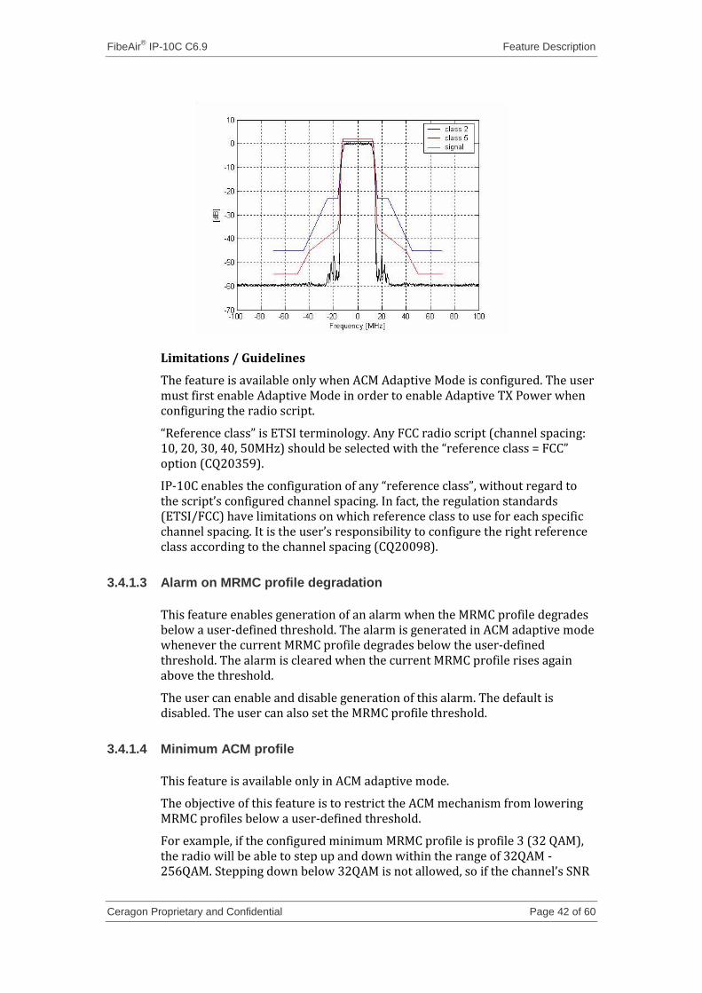
In the first scenario the user must plan the link according to a “low class” channel mask, and when radio path conditions allow it, the link will increase the modulation. This increase of modulation may require lowering the output power (see table below), in order to decrease the non-linearity of the transmitter for the higher constellations and in order for the transmitted spectrum to stay within the licensed “low class” channel mask. The following figure demonstrates the differences between a “low class” mask (e.g., class 2) and a “high class” mask (e.g., class 5):
FibeAir® IP-10C C6.9 Feature Description
Ceragon Proprietary and Confidential Page 42 of 60
Limitations / Guidelines
The feature is available only when ACM Adaptive Mode is configured. The user must first enable Adaptive Mode in order to enable Adaptive TX Power when configuring the radio script.
“Reference class” is ETSI terminology. Any FCC radio script (channel spacing: 10, 20, 30, 40, 50MHz) should be selected with the “reference class = FCC” option (CQ20359).
IP-10C enables the configuration of any “reference class”, without regard to the script’s configured channel spacing. In fact, the regulation standards (ETSI/FCC) have limitations on which reference class to use for each specific channel spacing. It is the user’s responsibility to configure the right reference class according to the channel spacing (CQ20098).
3.4.1.3 Alarm on MRMC profile degradation
This feature enables generation of an alarm when the MRMC profile degrades below a user-defined threshold. The alarm is generated in ACM adaptive mode whenever the current MRMC profile degrades below the user-defined threshold. The alarm is cleared when the current MRMC profile rises again above the threshold.
The user can enable and disable generation of this alarm. The default is disabled. The user can also set the MRMC profile threshold.
3.4.1.4 Minimum ACM profile
This feature is available only in ACM adaptive mode.
The objective of this feature is to restrict the ACM mechanism from lowering MRMC profiles below a user-defined threshold.
For example, if the configured minimum MRMC profile is profile 3 (32 QAM), the radio will be able to step up and down within the range of 32QAM - 256QAM. Stepping down below 32QAM is not allowed, so if the channel’s SNR
FibeAir® IP-10C C6.9 Feature Description
Ceragon Proprietary and Confidential Page 43 of 60
degrades below the 32QAM threshold, the radio will lose carrier synchronization, and will report Loss of Frame.
The user can enable and disable this feature. When the feature is enabled, the user can set the minimum MRMC profile. The default is disabled.
3.4.2 ATPC override timer
ATPC is a closed-loop mechanism by which each RFU changes the transmitted signal power according to the indication received across the link, in order to achieve a desired RSL on the other side of the link.
In the existing mechanism, in case of radio LOF the system automatically increases its transmit power to the configured maximum (as done when ATPC is disabled). This may cause a higher level of interference with other systems until the failure is corrected.
In order to minimize this interference, some regulators require a timer mechanism which will be manually overridden when the failure is fixed. The underlying principle is that the system should start a timer from the moment maximum power has been reached. If the timer expires, ATPC is overridden and the system transmits at a pre-determined power level until the user manually re-establishes ATPC and the system works normally again.
The user can configure the following parameters:
Override timeout (0 to disable the feature): The amount of time the timer counts from the moment the system transmits at the maximum configured power.
Override transmission power: The power that will be transmitted if ATPC is overridden because of timeout.
User can also display the current countdown value
When the system enters into the override state, ATPC is automatically disabled and the system will transmit at the pre-determined override power. An alarm is raised in this situation.
The only way to go back to normal operation is to manually cancel the override. When doing so, users should be sure that the problem has been corrected; otherwise, ATPC may be overridden again.
3.4.3 Alarm on RSL level degradation
This feature enables the generation of an alarm when the RSL level degrades below a user-defined threshold.
The user can enable or disable generation of this alarm. The default is disabled. The user can set the RSL nominal level in [dB] and the RSL degradation margin in [dB]. When enabled, an alarm is generated if the RSL level degrades below the nominal level minus the degradation margin. The alarm is cleared when the RSL level returns to a level above this point.
FibeAir® IP-10C C6.9 Feature Description
Ceragon Proprietary and Confidential Page 44 of 60
3.4.4 Enhanced Multi Layer header compression
Multi layer header compression provides a considerable capacity gain by compressing the redundant fields inside the packet headers. Multi Layer header compression provides the ability to compress the packet header up to L4. It is based on the principle that the packet headers in contemporary networks use a long protocol stack that contains a large amount of redundant information.
VoIP that is carried over RTP over TCP/IP provides an example of this principle. In this scenario, the packet payload is short (since long packets may affect latency) while each packet’s header contains TCP/IP headers. It is evident that each packet in this session will contain similar fields with constant values, such as the MAC address, VLAN tag, IP addresses, and TCP ports.
Multi layer header compression can be used to compress the following types of header stack:
Ethernet MAC untagged
IPv4
TCP
UDP
IPv6
TCP
UDP
MPLS
Ethernet MAC + VALN
IPv4
TCP
UDP
IPv6
TCP
UDP
MPLS
Ethernet MAC with QinQ
IPv4
TCP
UDP
IPv6
TCP
UDP
MPLS
PBB-TE
User configuration
Users can enable and disable compression and set the compression depth to one of the following:
FibeAir® IP-10C C6.9 Feature Description
Ceragon Proprietary and Confidential Page 45 of 60
L2 (Ethernet + MPLS)
L3 (Ethernet + IP)
L4 ( All supported layers up to L4)
Users can set the compression mode to Enhanced or Legacy mode.
Note: Software release C6.9 is the first software release for IP-10C. This release does not support interoperability over the link with other FibeAir IDU models, such as IP10-G and IP10-E.
Detailed functionality description
Multi layer header compression, when enabled, looks into each packet that egresses the radio port for known header patterns that can be compressed. First, each packet is classified and its protocol stack is revealed. For example, UDP over IPv4 over untagged Ethernet is one of the supported options (as listed above).
Second, all relevant header fields that can be compressed are extracted and checked in the hash list in the transmitter. If no match is found, the packet type is learned. Learning means that the packet header is placed inside a hashed lookup table in the TX side and the remote side will be indicated too. If the header matches a known header type, the packet is compressed, which means it is transmitted without the known header fields.
Upon receiving a compressed packet, the remote side reconstructs the omitted header fields from its own lookup table.
Hashed lookup tables have a limited number of entries. Thus, two mechanisms are used to keep the lookup table up to date: Aging and Refreshing.
The Aging mechanism deletes unused entries from the lookup table at a certain point in order to enable learning of additional header types.
Refreshing increases robustness and error recovery on the radio link by periodically forcing re-learning of each entry in the lookup table.
Note: Multi layer header compression is completely lossless. This means that no packets are dropped during normal operation, as well as during the learning, table aging, and refreshing processes.
Excluding rules
The learning lookup table is limited to 256 entries. To optimize compression rates, it is important to avoid over-population of the lookup table. Users can optimize compression performance by excluding flows that should not be compressed, according to the following rules:
By MAC destination address (DA) – 6 bytes DA
By MAC source address (SA) – 6 bytes SA
By Ethertype -2 bytes
By VLAN – 4 bytes (including VLAN Ethertype to identify S-VLAN from C-VLAN, VLAN Id and VLAN P-bits).
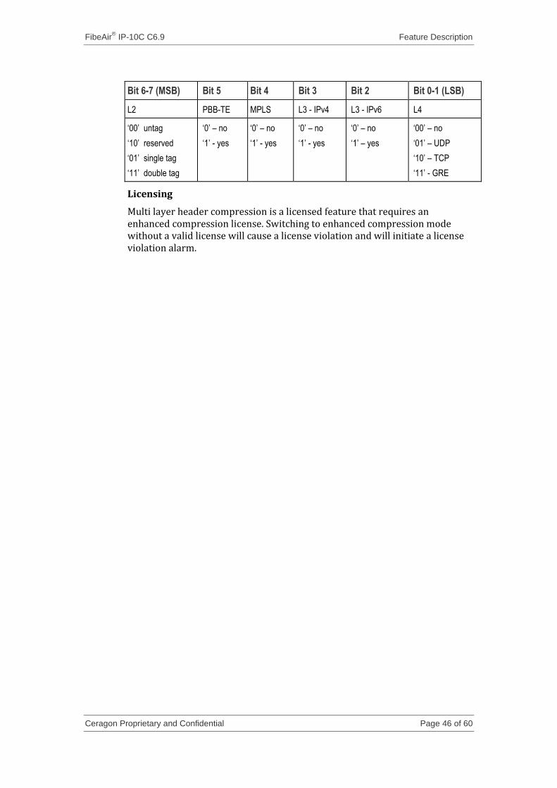
Flow type – 1 byte – according to the following bitmask
FibeAir® IP-10C C6.9 Feature Description
Ceragon Proprietary and Confidential Page 46 of 60
Bit 6-7 (MSB) Bit 5 Bit 4 Bit 3 Bit 2 Bit 0-1 (LSB)
L2 PBB-TE MPLS L3 - IPv4 L3 - IPv6 L4
„00‟ untag
„10‟ reserved
„01‟ single tag
„11‟ double tag
„0‟ – no
„1‟ - yes
„0‟ – no
„1‟ - yes
„0‟ – no
„1‟ - yes
„0‟ – no
„1‟ – yes
„00‟ – no
„01‟ – UDP
„10‟ – TCP
„11‟ - GRE
Licensing
Multi layer header compression is a licensed feature that requires an enhanced compression license. Switching to enhanced compression mode without a valid license will cause a license violation and will initiate a license violation alarm.
FibeAir® IP-10C C6.9 Feature Description
Ceragon Proprietary and Confidential Page 47 of 60
3.5 Security
Security features are relevant to the following areas:
User access control: Allowing only authorized users to access the system.
Secure communication channels: End-to-end encrypted channels for management.
Security log: A tool to analyze undesired or unauthorized changes in the system security configuration.
Note: Security features can be configured by users with “administrator” privileges, via the Web-Based EMS or the CLI
3.5.1 User access control
The following features are supported:
Configurable inactivity time-out for closing management channels
Password strength is enforced; passwords must comply with the following rules:
Be at least 8 characters long
Include both numbers and letters (or spaces, symbols, etc.)
Include both uppercase and lowercase letters
When calculating the number of character classes, upper-case letters used as the first character and digits used as the last character of a password are not counted
A password cannot be repeated within the past 5 password changes
Password aging: users will be prompted to change passwords after a configurable amount of time
When new users log in for the first time, the system can force them to change their password. This feature can be enabled and disabled. It is enabled by default.
Users may be suspended after a configurable number of unsuccessful login attempts
Users can be configured to expire at a certain date
3.5.2 Secure communication channels
This feature consists of support for a number of standard encryption protocols and algorithms.
FibeAir® IP-10C C6.9 Feature Description
Ceragon Proprietary and Confidential Page 48 of 60
3.5.2.1 SSH (Secured Shell)
SHHv1 and SSHv2 are supported.
SSH protocol will be used as a secured alternative to Telnet.
SSH protocol will always be operational. Admin users can choose whether to disable Telnet protocol, which will be enabled" by default. Server authentication will be based on IP-10C’s public key.
The key exchange algorithm is RSA.
Supported Encryptions: aes128-cbc, 3des-cbc, blowfish-cbc, cast128-cbc, arcfour128, arcfour256, arcfour, aes192-cbc, aes256-cbc, aes128-ctr, aes192-ctr, aes256-ctr.
MAC (Message Authentication Code): SHA-1-96 (MAC length = 96 bits, key length = 160 bit). Supported MAC: hmac-md5, hmac-sha1, hmac-ripemd160, hmac-sha1-96, hmac-md5-96'
The server will authenticate the user based on user name and password. The number of failed authentication attempts is not limited.
Server timeout for authentication: 10 minutes. This value cannot be changed.
3.5.2.2 HTTPS (Hypertext Transfer Protocol Secure)
In order to manage the system using HTTPS protocol, users should follow these steps (CQ15826 – 3):
1 Create the IP-10C certificate based on the IP-10C’s public key. 2 Download the IP-10C certificate. 3 Optionally, to use the CA certificate:
i Download the IP-10C CA's certificate. ii Enable WEB CA certificate.
4 Set the WEB Protocol parameter to HTTPS.
Step1: Public Key Upload
The public key should be uploaded by the user for generating the IP-10C’s digital certificate. Uploads are performed using FTP/SFTP. The public key file will be in PEM format.
From the Security Configuration page in the Web-Based EMS, click
Upload Public Key.
Note: The user must have operator privileges to use this command.
The status of the upload operation can be monitored in the Web-Based EMS. The returned status values are: “ready” (default), “in-progress”, “success”, and “failed”. In case of failure, an appropriate error message will appear.
FibeAir® IP-10C C6.9 Feature Description
Ceragon Proprietary and Confidential Page 49 of 60
Step 2: Download IP-10C server certificate and/or IP-10C CA certificate (optional)
Downloads are performed using FTP/SFTP. PEM and DER certificate formats are supported.
For downloading the IP-10C server certificate and/or the IP-10C's CA certificate to the system, the following steps must be performed for each file type:
Note: To perform this procedure, the user must have “Admin” privileges.
1 Determine the certificate file name. . 2 Determine the certificate file type: “Target Certificate” (for WEB server
digital certificate) or “Target CA certificate” (for WEB CA digital certificate).
3 Determine certificate file format: PEM (for PEM formatted file) or DER (for DER formatted file).
4 Determine whether or not to include the CA certificate in the Web-Based EMS configuration definitions. This is an optional configuration and is recommended for adapting the Web-Based EMS to all browser applications.
5 After setting the above configurations, go to the Security Configuration page in the Web-Based EMS and click Download Certificate. Users can monitor the status of the download operation in the Web-Based EMS. Possible status values are: “ready”, “in-progress”, “success”, and “failed”.
6 It is recommended to refresh the Security Configuration page once the certificate download operation is complete (CQ19554).
7 To apply the new certificate, the web server should be restarted. The web server is automatically restarted when it is configured to HTTPS.
Step3: Activate HTTPS
The web interface protocol can be configured to HTTP (default) or HTTPS (cannot be both at the same time).
Note: For security reasons, this parameter is NOT copied by a “copy to mate” operation. An unsecured unit should not be able to override the security parameters of a secured unit just by performing a “copy to mate” operation.
While switching to HTTPS mode, the following conditions must exist:
A WEB server certificate file must exist.
The certificate’s public key must be compatible with the IP-10C’s private key.
If one of these conditions does not exist, the operation will return an appropriate error indication.
To activate HTTPS, open the web browser and type the following URL: https:\\<IP of target IP-10C>
FibeAir® IP-10C C6.9 Feature Description
Ceragon Proprietary and Confidential Page 50 of 60
3.5.2.3 SFTP (Secure FTP)
SFTP can be used for the following operations:
Configuration upload and download,
Uploading unit information
Uploading a public key
Downloading certificate files
Downloading software
Recommended SFTP (Freeware) servers
freeSSHd : http://www.freesshd.com/?ctt=download
msftpsrvr: http://www.download3k.com/Install-CoreFTP.com-Core-FTP-Mini-SFTP-Server.html
3.5.2.4 Creation of Certificate Signing Request (CSR) file
In order to create a digital certificate for the Network Element (NE), a Certificate Signing Request (CSR) file should be created by the NE. The CSR contains information that will be included in the NE's certificate such as the organization name, common name (domain name), locality, and country. It also contains the public key that will be included in the certificate. Certificate authority (CA) will use the CSR to create the desired certificate for the NE.
While creating the CSR file, the user will be asked to input the following parameters that should be known to the operator who applies the command:
Common name – The identify name of the element in the network (e.g., the IP address). The common name can be a network IP or the FQDN of the element.
Organization – The legal name of the organization.
Organizational Unit - The division of the organization handling the certificate.
City/Locality - The city where the organization is located.
State/County/Region - The state/region where the organization is located.
Country - The two-letter ISO code for the country where the organization is location.
Email address - An email address used to contact the organization.
To create a CSR file:
1 Use the create-csr CLI command to create CSR file. 2 Input the identification parameters described above. 3 Optionally, the user can view the CSR file in text format using the csr-show
CLI command or via the Web-Based EMS. 4 Upload the CSR file from the NE to the remote server. In order to upload
the file:
i Set the FTP parameters. ii Set the file name of the uploaded file, by using the security-file-name
parameter.
FibeAir® IP-10C C6.9 Feature Description
Ceragon Proprietary and Confidential Page 51 of 60
iii Apply command upload-archive csr-file.
5 Verify the upload status by viewing the upload-security-status parameter.
The CSR file can be also created from the Web-Based EMS.
3.5.3 Security log
The security log is an internal system file which records all changes performed to any security feature, as well as all security – related events.
The security log file has the following attributes:
The file is of a “cyclic” nature (fixed size, newest events overwrite oldest).
Readable only by users with "admin" or above privilege
The log can be viewed using the following command:
/management/mng-services/ event-service/event-log/view-security-log
The contents of the log file are cryptographically protected and digitally signed.
In the event of an attempt to modify the file, an alarm will be raised
Users may not overwrite, delete, or modify the file
The following information is recorded in the log:
Changes in security configuration:
Carrying out “security configuration copy to mate”
Management channels time-out
Password aging time
Number of unsuccessful login attempts for user suspension
Warning banner change
Adding/deleting of users
Password changed
SNMP enable/disable
SNMP version used (v1/v3) change
SNMPv3 parameters change
Security mode
Authentication algorithm
User
Password
SNMPv1 parameters change
Read community
Write community
Trap community for any manager
HTTP/HTTPS change
FTP/SFTP change
Telnet and web interface enable/disable
FibeAir® IP-10C C6.9 Feature Description
Ceragon Proprietary and Confidential Page 52 of 60
FTP enable/disable
Loading certificates
RADIUS server and NAS parameters (IP address) change
RADIUS enable/disable
Remote logging enable/disable (for security and configuration logs)
Syslog server address change (for security and configuration logs)
System clock change
NTP enable/disable
Security events
Successful and unsuccessful login attempts
N consecutive unsuccessful login attempts (blocking)
Configuration change failure due to insufficient permissions
SNMPv3/PV (HTTP) authentication failure
User logout
User Account expired
For each recorded event the following information is available:
User ID
Communication channel (WEB, terminal, telnet/SSH, SNMP, XML, etc.)
IP address, if applicable
Date and time
FibeAir® IP-10C C6.9 Feature Description
Ceragon Proprietary and Confidential Page 53 of 60
3.6 System management
3.6.1 Alarms editing
It is possible for users to change the description text (by appending extra text to the existing description) or the severity of any alarm in the system. This feature is available through CLI only.
This is performed as follows:
Each alarm in the system is identified by a unique name (see separate list of system alarms and events).
The user can perform the following operations on any alarm:
View current description and severity
Define the text to be appended to the description and/or severity
Return the alarm to its default values
The user can also return all alarms and events to their default values.
3.6.2 System software interfaces
3.6.2.1 CLI (Command Line Interface)
A CLI connection to the IP-10C can be opened via terminal (serial COM, speed: 115200, Data: 8 bits, Stop: 1 bit, Flow-Control: None), or via telnet (SSH is supported as well). “Terminal” format should be VT-100 with screen definition of 80 columns X 24 rows.
All parameter configurations can be performed via CLI.
When configuring the L2-Switch, it is essential to issue a write command in order to save the configuration to the disk. If write is not issued, the configuration will take effect, but will revert back to the previous saved value the next time a cold-reset is performed.
3.6.2.2 Web-Based EMS
A Web-Based EMS connection to the IP-10C can be opened using an HTTP Browser (Explorer or Mozilla Firefox). To open a connection, open the browser and type http://ip_address. For example, if the IP address of the IP-10C is 192.168.1.1, type: http://192.168.1.1 to open a session with the IP-10C via the Web-Based EMS. If HTTPS protocol is used, type: https://192.168.1.1
The Web-Based EMS uses a graphical interface, and is much more user-friendly than the CLI. All system configurations and statuses are available via the Web-Based EMS, including all L2-Switch configurations (port type, VLANs, QoS, etc.).
When L2-Switch parameters are configured, it is important to click Apply in order to save the configuration to the disk.
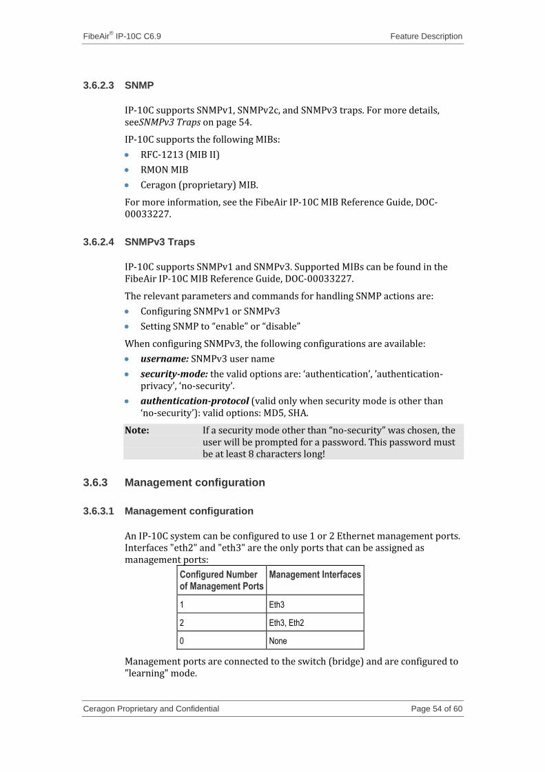
FibeAir® IP-10C C6.9 Feature Description
Ceragon Proprietary and Confidential Page 54 of 60
3.6.2.3 SNMP
IP-10C supports SNMPv1, SNMPv2c, and SNMPv3 traps. For more details, seeSNMPv3 Traps on page 54.
IP-10C supports the following MIBs:
RFC-1213 (MIB II)
RMON MIB
Ceragon (proprietary) MIB.
For more information, see the FibeAir IP-10C MIB Reference Guide, DOC-00033227.
3.6.2.4 SNMPv3 Traps
IP-10C supports SNMPv1 and SNMPv3. Supported MIBs can be found in the FibeAir IP-10C MIB Reference Guide, DOC-00033227.
The relevant parameters and commands for handling SNMP actions are:
Configuring SNMPv1 or SNMPv3
Setting SNMP to “enable” or “disable”
When configuring SNMPv3, the following configurations are available:
username: SNMPv3 user name
security-mode: the valid options are: ‘authentication’, ’authentication-privacy’, ‘no-security’.
authentication-protocol (valid only when security mode is other than ‘no-security’): valid options: MD5, SHA.
Note: If a security mode other than “no-security” was chosen, the user will be prompted for a password. This password must be at least 8 characters long!
3.6.3 Management configuration
3.6.3.1 Management configuration
An IP-10C system can be configured to use 1 or 2 Ethernet management ports. Interfaces "eth2" and "eth3" are the only ports that can be assigned as management ports:
Configured Number of Management Ports
Management Interfaces
1 Eth3
2 Eth3, Eth2
0 None
Management ports are connected to the switch (bridge) and are configured to "learning" mode.
FibeAir® IP-10C C6.9 Feature Description
Ceragon Proprietary and Confidential Page 55 of 60
3.6.3.2 Management frame priority
Management frames should always be assigned maximum priority in order to ensure that network management remains available in a heavily utilized network.
In order to achieve this, the IP-10C marks all management frames (frames incoming from the management ports) with Layer-2 pbits value 7; this is the highest priority by default.
3.6.3.3 Management capacity
Management ports can be configured to have one of the following capacities: 64kbps, 128kbps, 256kbps, 512kbps, 1024kbps, 2048kbps (default). Capacity is limited by the port ingress rate limit.
3.6.3.4 Out-of-Band management (default)
With Out-of-Band management, the remote system is managed using an Ethernet management channel provided by third party equipment.
Ethernet port 2 and Ethernet port 3 can be used to chain management from one unit to another.
Management frames that ingress from the management ports must not be VLAN tagged. Tagged frames will be discarded.
3.6.3.5 In-Band management
With In-Band management, the remote IP-10C is managed by specific frames that are sent as part of the traffic. These frames are identified as management frames by a special VLAN ID configured by the user. This VLAN ID must be used ONLY for management. It is NOT possible to configure more than a single VLAN ID for management.
Important: It is highly recommended to classify the management VLAN ID to the highest queue, in order to ensure the ability to manage remote units even under congestion scenarios (CQ19186).
The local unit is the gateway for In-Band management. The remote unit is managed via its traffic ports (the radio port, for example), so that no management ports are needed on the remote unit.
Avoiding Ethernet Loops
When configuring the system to In-Band management, it is essential to avoid Ethernet loops, as shown in the following figures. It is necessary to transport management traffic to the main unit by using external Ethernet cables.
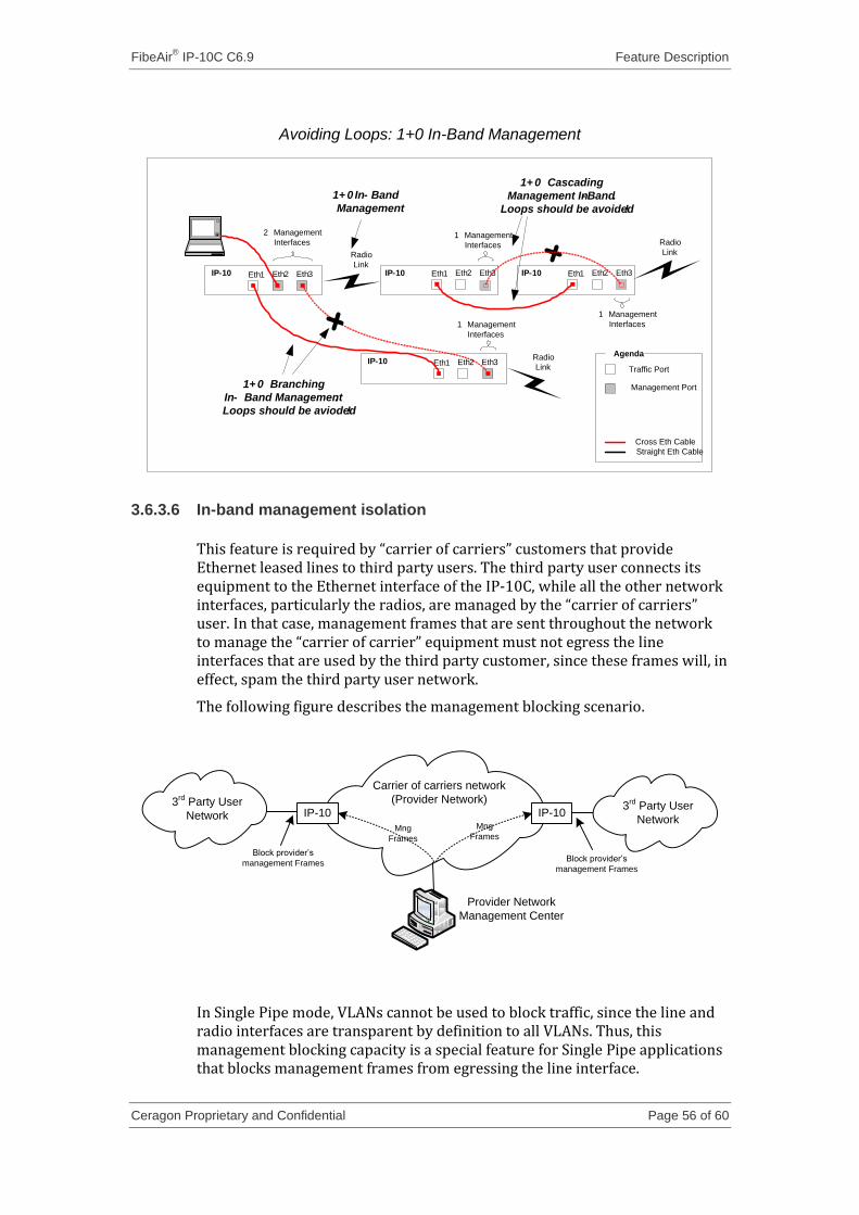
FibeAir® IP-10C C6.9 Feature Description
Ceragon Proprietary and Confidential Page 56 of 60
Avoiding Loops: 1+0 In-Band Management
Eth2
2 Management
Interfaces
Eth3Eth1IP-10
Eth2 Eth3Eth1IP-10
Radio
LinkEth2 Eth3Eth1
1 Management
Interfaces
IP-10 Eth2 Eth3Eth1
1 Management
Interfaces
IP-10
1+ 0 In- Band
Management
1+ 0 Cascading
Management In- Band.
Loops should be avoided !
1+ 0 Branching
In- Band Management.
Loops should be avioded !
Agenda
Traffic Port
Management Port
Cross Eth Cable
Straight Eth Cable
Radio
Link
Radio
Link
1 Management
Interfaces
3.6.3.6 In-band management isolation
This feature is required by “carrier of carriers” customers that provide Ethernet leased lines to third party users. The third party user connects its equipment to the Ethernet interface of the IP-10C, while all the other network interfaces, particularly the radios, are managed by the “carrier of carriers” user. In that case, management frames that are sent throughout the network to manage the “carrier of carrier” equipment must not egress the line interfaces that are used by the third party customer, since these frames will, in effect, spam the third party user network.
The following figure describes the management blocking scenario.
IP-10 IP-10
Provider Network
Management Center
Mng
Frames
Carrier of carriers network
(Provider Network)
Mng
Frames
Block provider’s
management FramesBlock provider’s
management Frames
3rd
Party User
Network3
rd Party User
Network
In Single Pipe mode, VLANs cannot be used to block traffic, since the line and radio interfaces are transparent by definition to all VLANs. Thus, this management blocking capacity is a special feature for Single Pipe applications that blocks management frames from egressing the line interface.
FibeAir® IP-10C C6.9 Feature Description
Ceragon Proprietary and Confidential Page 57 of 60
Management isolation and blocking behavior is controlled by the block-management-towards-line CLI parameter. The default is disable (not blocked).
3.6.4 Downloading text CLI configuration scripts
3.6.4.1 General overview
CLI configuration text scripts, written in Ceragon CLI format, can be downloaded into the IP-10C. It is impossible to upload the IP-10C’s configuration into a text file.
CLI scripts can only be downloaded and handled via CLI. CLI scripts cannot be downloaded via the Web-Based EMS. All CLI commands that handle CLI scripts reside at:
/platform/idc-board/
The user can perform the following operations on CLI scripts:
Set the file name of the script:
set /platform/idc-board/cli-script-file-name <text_file_name>
Download CLI script file to the IP-10C. It is recommended to first check the FTP parameters, which are available in the Web-Based EMS Configuration Management page. The FTP parameters can be set or get also via CLI:
Get protocol type: get /platform/idc-board/file-transfer-protocol
Get Host IP: get /platform/idc-board/host-ip
Get the host path: get /platform/idc-board/host-path
Get the user name get /platform/idc-board/user-name
Change user password: set /platform/idc-board> change-user-password
Download the CLI script file:
set /platform/idc-board/download-archive cli-script
Get the status of the downloaded script.
get /platform/idc-board/download-cli-script-status
The return values can be: “succeeded” or “failed”.
Show the last downloaded CLI script content.
set /platform/idc-board/cli-script show
This operation returns the text content of the downloaded script to the console.
Execute (activate) a CLI script.
set /platform/idc-board/cli-script execute
Delete current script which resides inside the IP-10C.
set /platform/idc-board/cli-script delete.
This operation requires user confirmation.
The following events are intended to help the user control the configuration procedure:
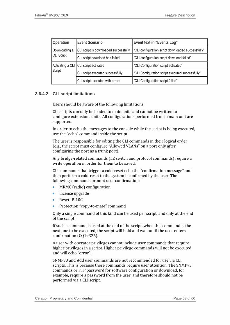
FibeAir® IP-10C C6.9 Feature Description
Ceragon Proprietary and Confidential Page 58 of 60
Operation Event Scenario Event text in “Events Log”
Downloading a
CLI Script
CLI script is downloaded successfully “CLI configuration script downloaded successfully”
CLI script download has failed “CLI configuration script download failed”
Activating a CLI
Script
CLI script activated “CLI Configuration script activated”
CLI script executed successfully “CLI Configuration script executed successfully”
CLI script executed with errors “CLI Configuration script failed”
3.6.4.2 CLI script limitations
Users should be aware of the following limitations:
CLI scripts can only be loaded to main units and cannot be written to configure extensions units. All configurations performed from a main unit are supported.
In order to echo the messages to the console while the script is being executed, use the “echo” command inside the script.
The user is responsible for editing the CLI commands in their logical order (e.g., the script must configure “Allowed VLANs” on a port only after configuring the port as a trunk port).
Any bridge-related commands (L2 switch and protocol commands) require a write operation in order for them to be saved.
CLI commands that trigger a cold-reset echo the “confirmation message” and then perform a cold-reset to the system if confirmed by the user. The following commands prompt user confirmation:
MRMC (radio) configuration
License upgrade
Reset IP-10C
Protection “copy-to-mate” command
Only a single command of this kind can be used per script, and only at the end of the script!
If such a command is used at the end of the script, when this command is the next one to be executed, the script will hold and wait until the user enters confirmation (CQ19326).
A user with operator privileges cannot include user commands that require higher privileges in a script. Higher privilege commands will not be executed and will echo “error”.
SNMPv3 and Add user commands are not recommended for use via CLI scripts. This is because these commands require user attention. The SNMPv3 commands or FTP password for software configuration or download, for example, require a password from the user, and therefore should not be performed via a CLI script.
FibeAir® IP-10C C6.9 Feature Description
Ceragon Proprietary and Confidential Page 59 of 60
3.6.5 Language support
Users should be aware of the following limitations regarding the usage of “non standard ASCII” (ASCII 7) characters:
Web-Based EMS
Web browser encoding is automatically set to “UTF-8”, for proper functionality of the Web-Based EMS. No other encoding type is available (CQ18826).
Any bridge-related (L2 switching machine or L2 protocols) free text must be in “standard ASCII” (ASCII 7), e.g.,”, “Policer Name”, “Class-map Name”, etc. Any usage of non-standard ASCII characters will be rejected by the system, returning a “Bad Character” error message.
Any other free text fields (which are not related to the L2 switch) can be populated by text in any language, e.g.,. “System Name”, “System Location”, “Contact Person”, etc.
User names and passwords must be typed in Standard ASCII (ASCII 7). Otherwise, they will be rejected by the system, which returns a “Bad Character” error message.
It is recommended to use only ASCII 7 format characters when configuring SNMP-related parameters via the Web-Based EMS (e.g., CLLI) in order to avoid gibberish when these parameters are obtained via an SNMP interface, which supports only ASCII 7 format (CQ21324).
Note: The following non standard ASCII languages have been tested: German, Hungarian, Finnish, Swedish, French and Russian/Cyrillic (CQ18822 / 20700).
CLI / SNMP (MIB) Interface
Only Standard ASCII (ASCII 7) is supported for all free text fields. Any attempt to enter free text in a format than ASCII 7 will be rejected by the system, which returns a “Bad Character” error message (CQ 20490 / 20832 / 20833).
3.6.6 NTP
IP-10C supports NTP client. If the user enables this capability, the user should enter the IP address of the NTP server on which the user wants the IP-10C to be locked.
The NTP client returns one of the following “Sync” statuses:
If locked, it returns the IP address of the server it is locked on.
Loca – The NTP client is locked on the local element’s real-time clock.
NA - The NTP client is not synchronized with any clock (valid only when Admin is set to Disable).
The feature supports Time Offset and Daylight Savings Time.
Time Offset and Daylight Savings Time can be configured via the Unit Information page of the Web-Based EMS, or via the following CLI command:
/management/mng-services/time-service>
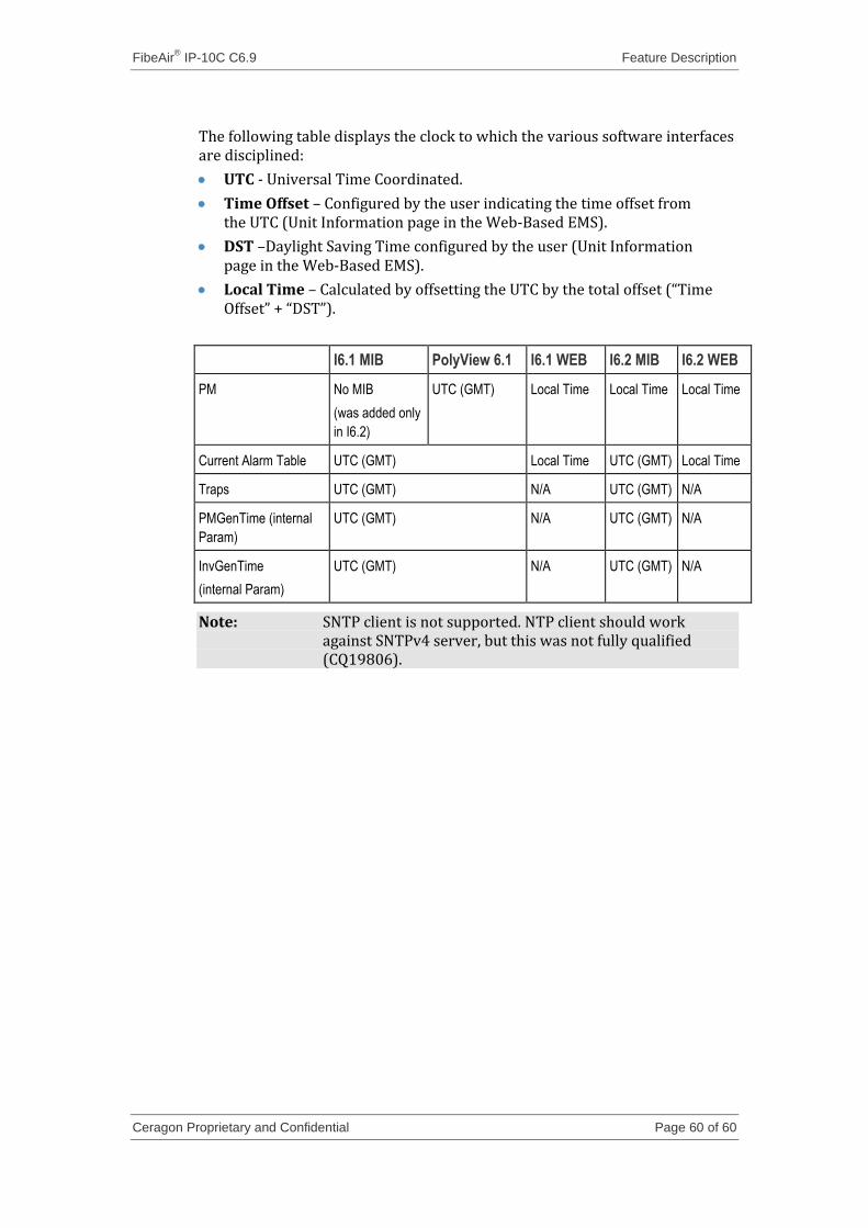
FibeAir® IP-10C C6.9 Feature Description
Ceragon Proprietary and Confidential Page 60 of 60
The following table displays the clock to which the various software interfaces are disciplined:
UTC - Universal Time Coordinated.
Time Offset – Configured by the user indicating the time offset from the UTC (Unit Information page in the Web-Based EMS).
DST –Daylight Saving Time configured by the user (Unit Information page in the Web-Based EMS).
Local Time – Calculated by offsetting the UTC by the total offset (“Time Offset” + “DST”).
I6.1 MIB PolyView 6.1 I6.1 WEB I6.2 MIB I6.2 WEB
PM No MIB
(was added only
in I6.2)
UTC (GMT) Local Time Local Time Local Time
Current Alarm Table UTC (GMT) Local Time UTC (GMT) Local Time
Traps UTC (GMT) N/A UTC (GMT) N/A
PMGenTime (internal
Param)
UTC (GMT) N/A UTC (GMT) N/A
InvGenTime
(internal Param)
UTC (GMT) N/A UTC (GMT) N/A
Note: SNTP client is not supported. NTP client should work against SNTPv4 server, but this was not fully qualified (CQ19806).