feature analysis of electromagnetic interference ... · feature analysis of electromagnetic...
TRANSCRIPT
Feature Analysis of Electromagnetic Interference Measurement Facilities
1Eugene Rhee, 2Changjae Kim 1, First AuthorDept. of Computer System Engineering, Sangmyung University, Korea,
[email protected] *2,Corresponding AuthorDept. of Civil Engineering, Sangmyung University, Korea, [email protected]
Abstract
This paper presents a feature analysis of two electromagnetic interference test facilities. The one is an anechoic chamber and the other is a reverberation chamber. And then, this paper reviews problems of the current reverberation chamber, the stirrer. In general, a reverberation chamber uses a stirrer to generate a uniform electric field inside it. However, the stirrer is a big sized unit and has rotating parts in it, which makes problems and difficulties in maintenance. To conquest these problems, this paper suggests a diffuser which is commonly used in acoustics. To study the substitution effect of a diffuser, a diffuser and a reverberation chamber for 5.0-7.0 GHz band are designed and fabricated. And then, the real measurement of electric field intensity is done to study the electromagnetic interference characteristics in a reverberation chamber with a diffuser. With the measurement results, it is show that a diffuser satisfies the international standard requirement, which means the reverberation chamber with a diffuser can be used as an official facility for the electromagnetic interference measurement.
Keywords: Electromagnetic Compatibility, Electromagnetic Interference, Reverberation Chamber
1. Introduction
Today, the wide spread use of electronic circuits for communication, computation, automation, and
other purpose makes it necessary for diverse circuits to operate in close proximity. All too often these circuits affect each other adversely. Electromagnetic interference has become a major problem for circuit designers, and it is becoming more severe these days [1-17].
An anechoic chamber (an-echoic meaning non-echoing or echo-free) is a room designed to completely absorb reflections of either sound or electromagnetic waves. As shown in Figure 1, it is also insulated from exterior sources of noise. The combination of both aspects means they simulate a quiet open-space of infinite dimension, which is useful when exterior influences would otherwise give false results. Anechoic chambers, a term coined by American acoustics expert Leo Beranek, were originally used in the context of acoustics (sound waves) to minimize the reflections of a room [18]. More recently, rooms designed to reduce reflection and external noise in radio frequencies have been used to test equipment under test (EUT), antennas, radars, or electromagnetic interference.
On the other hand, the concept of a reverberation chamber was suggested by H. A. Mendes in 1968 and it has been studied to be used as a measurement facility for electromagnetic interference tests by National Bureau of Standards (NBS) [19][20]. And International Special Committee on Radio Interference (CISPR) under International Electro-technical Commission (IEC) has established various international standards related to a reverberation chamber [21][22]. Moreover, as the recent international standard expanded the regulation frequency band for electromagnetic interference to 1-18 GHz, the reverberation chamber is given much prominence today [21]. As shown in Figure 2, a reverberation chamber is screened room with a minimum of absorption of electromagnetic energy. Due to the low absorption, very high field strength can be achieved with moderate input power. Therefore, the spatial distribution of the electric and magnetic field strength is strongly inhomogeneous (standing waves). To reduce this inhomogeneity, one or more stirrers are used. A stirrer is a construction with large metallic reflectors that can rotate to different orientations in order to get different boundary conditions. The lowest usable frequency (LUF) of a reverberation chamber depends on the size of the chamber and the structure of the stirrer [19][20]. Small chambers have a higher LUF than large chambers.
Feature Analysis of Electromagnetic Interference Measurement Facilities Eugene Rhee, Changjae Kim
International Journal of Digital Content Technology and its Applications(JDCTA) Volume 7, Number 10, June 2013 doi : 10.4156/jdcta.vol7.issue10.16
155

Figure 1. Structure of an anechoic chamber
Figure 2. Structure of a reverberation chamber
Feature Analysis of Electromagnetic Interference Measurement Facilities Eugene Rhee, Changjae Kim
156
2. Diffuser
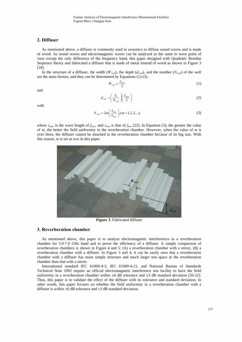
As mentioned above, a diffuser is commonly used in acoustics to diffuse sound waves and is made of wood. As sound waves and electromagnetic waves can be analyzed as the same in wave point of view except the only difference of the frequency band, this paper designed with Quadratic Residue Sequence theory and fabricated a diffuser that is made of metal instead of wood as shown in Figure 3 [18].
In the structure of a diffuser, the width (Wwell), the depth (dwell), and the number (Nwell) of the well are the main factors, and they can be determined by Equations (1)-(3).
2
max
wellW (1)
and
2
n min
wellwell
Sd
N (2)
with
2 ,( 1,2,3,...),
minwell
max
N m m (3)
where λmax is the wave length of fmax, and λmin is that of fmin [22]. In Equation (3), the greater the value of m, the better the field uniformity in the reverberation chamber. However, when the value of m is over three, the diffuser cannot be attached in the reverberation chamber because of its big size. With this reason, m is set as two in this paper.
Figure 3. Fabricated diffuser
3. Reverberation chamber
As mentioned above, this paper is to analyze electromagnetic interferences in a reverberation
chamber for 5.0-7.0 GHz band and to prove the efficiency of a diffuser. A simple comparison of reverberation chambers is shown in Figure 4 and 5: (A) a reverberation chamber with a stirrer, (B) a reverberation chamber with a diffuser. In Figure 3 and 4, it can be easily seen that a reverberation chamber with a diffuser has more simple structure and much larger test space in the reverberation chamber than that with a stirrer.
International standard IEC 61000-4-3, IEC 61000-4-21, and National Bureau of Standards Technical Note 1092 require an official electromagnetic interference test facility to have the field uniformity in a reverberation chamber within ±6 dB tolerance and ±3 dB standard deviation [20-22]. Thus, this paper is to validate the effect of the diffuser with its tolerance and standard deviation. In other words, this paper focuses on whether the field uniformity in a reverberation chamber with a diffuser is within ±6 dB tolerance and ±3 dB standard deviation.
Feature Analysis of Electromagnetic Interference Measurement Facilities Eugene Rhee, Changjae Kim
157

Figure 4. Reverberation chamber with a stirrer
Figure 5. Reverberation chamber with a diffuser
4. Measurement
In this paper, all the measurement method and procedure for analyzing the field uniformity in the
reverberation chamber with a diffuser are followed by those of IEC 61000-4-3 and IEC 61000-4-21 international standards [21][22]. To validate the substitution effect of the designed diffuser, the measurement for analyzing the electric field uniformity in the reverberation chamber was done. The positions of the test volume, a diffuser, and the transmitting antenna as a source point are as shown in Figure 6. Electric field strengths are sampled at 80 test points in a test volume [23-25].
The detail structure of the test volume and test points is as shown in Figure 7. The test volume for analyzing the electric field uniformity in the reverberation chamber has five test planes, and each test plane has 16 test points. Thus, the total number of the test point is 80 (16 test points per a test plane five test planes) [24][25].
Feature Analysis of Electromagnetic Interference Measurement Facilities Eugene Rhee, Changjae Kim
158

Figure 6. Measurement set up
Figure 7. Five test planes and X=70 plane
Feature Analysis of Electromagnetic Interference Measurement Facilities Eugene Rhee, Changjae Kim
159

5. Measurement result
A signal generator (HP/Agilent, Model: E4433B) generated signals of 1 V at 5, 6, and 7 GHz, and the electric field strengths for each frequency is measured with an isotropic field probe (Amplifier Research, Model: FP5080).
As previously mentioned above, this paper focuses on whether the field uniformity in a reverberation chamber with a diffuser satisfies the requirement of the international standard, ±6 dB tolerance and ±3 dB standard deviation [20]. Table 1 shows the measured electric field strength in the reverberation chamber with a diffuser. Moreover, it also shows that the electromagnetic interference test requirements of NBS, the tolerance and the standard deviation, are satisfied by the diffuser.
Figure 8. Measurement system
Table 1. Measurement result
Electric field strength [dBμV/m] Requirement of NBS [dB]
Frequency Max. Min. Average Tolerance Standard
deviations 5 GHz 63.8 60.9 62.3 2.9 5.9 6 GHz 63.1 60.2 61.6 2.9 5.9 7 GHz 62.7 59.9 61.3 2.8 5.7
6. Conclusion
With the measurements, the sampled data of the electric field strength were analyzed to investigate
the electric field characteristics inside a reverberation chamber. The measurement results show that the field uniformity in the reverberation chamber with a diffuser meets ±6 dB tolerance and ±3 dB standard deviation of field uniformity characteristics, and this means that the requirement of NBS for the field uniformity condition at 5, 6, and 7 GHz was obtained by the fabricated diffuser.
7. Acknowledgement
This research was supported by a 2013 Research Grant from Sangmyung University.
Feature Analysis of Electromagnetic Interference Measurement Facilities Eugene Rhee, Changjae Kim
160

8. References
[1] Yan Liang, Chunming Rong, “Strengthen RFID Tags Security Using New Data Structure”, International Journal of Control and Automation, SERSC, vol. 1, no. 1, pp.51-58, 2008.
[2] Chin-Tae Choi, Ki-Sung You, Hee-Don Jeong, “Automatic Coil-handling Crane Control System”, International Journal of Control and Automation, SERSC, vol. 2, no. 1, pp.23-30, 2009.
[3] Roman Neruda, Stanislav Slusny, “Performance Comparison of Two Reinforcement Learning Algorithms for Small Mobile Robots”, International Journal of Control and Automation, SERSC, vol. 2, no. 1, pp.59-68, 2009.
[4] Joo-Hyung Kim, Dong-Won Kim, Bum-Jae You, Gwi-Tae Park, “A Design of Framework for Smart Services of robots in Intelligent Environment”, International Journal of Control and Automation, SERSC, vol. 2, no. 4, pp.1-12, 2009.
[5] Timir Maitra, Anindya J Pal, Debnath Bhattacharyya, Tai-Hoon Kim, “Noise Reduction in VLSI Circuits using Modified GA Based Graph Coloring”, International Journal of Control and Automation, SERSC, vol. 3, no. 2, pp.37-44, 2010.
[6] Mayank Chakraverty, Sandeep Mandava, Gargi Mishra, “Performance Analysis of CMOS Single Ended Low Power Low Noise Amplifier”, International Journal of Control and Automation, SERSC, vol. 3, no. 2, pp.45-52, 2010.
[7] Seung-Joon Lee, Dong-Hwan Shin, Yong-Hwa Kim, Jae-Jo Lee, “Analysis and Modeling of Noise on 22.9-kV Underground Power Distribution Cable for Broadband Power Line Communication”, International Journal of Control and Automation, SERSC, vol. 3, no. 3, pp.1-12, 2010.
[8] Tae-Young Byun, “A Performance Measurements of Inter-vehicle Communication System over Wireless WANs”, International Journal of Control and Automation, SERSC, vol. 3, no. 3, pp.41-54, 2010.
[9] A. M. Gaur, Rajesh Kumar, Amod Kumar, Dinesh Singh Rana, “PLC Based Automatic Control of Rheometer”, International Journal of Control and Automation, SERSC, vol. 3, no. 4, pp.11-20, 2010.
[10] Faramarz Asharif, Shiro Tamaki, Tsutomu Nagado, Tomokazu Nagata, Mohammad Reza Asharif, “Design of Low Frequency and Decoupling Compensator for MIMO System Including Time-delay Elements and Interferences”, International Journal of Control and Automation, SERSC, vol. 4, no. 1, pp.33-48, 2011.
[11] Jeong-Sik Lee, Kyung-Hun Kim, Ki-Yoon Jung, “Cellular Phone Electromagnetic Field Effect on the Melatonin Receptor Expression in the Mouse Brain”, Journal of Korea Academia-Industrial Cooperation Society, KAIS, vol. 6, no. 2, pp.183-188, 2005.
[12] Jeong-Tae Kwon, Seo-Hyun Kim, Taek-Hoon Nahm, Hyo-Jae Lim, Chang-Eob Kim, “Design of an Electromagnetic Pump and Numerical Analysis of the Liquid Metal Flow”, Journal of Korea Academia-Industrial Cooperation Society, KAIS, vol. 10, no. 10, pp.2589-2595, 2009.
[13] Hyun-Seob Cho, In-Ho Ryu, “A Study on Properties of Piezoelectric Ceramic Transformers”, Journal of Korea Academia-Industrial Cooperation Society, KAIS, vol. 10, no. 10, pp. 2660-2664, 2009.
[14] Tai-Heoun, Park, Man-Gyu, Park, Sang-Heup Park, Key-Sun Kim, “The Study on a Fixing-clip of a Shield Can Shielding Electromagnetic Wave”, Journal of Korea Academia-Industrial Cooperation Society, KAIS, vol. 14, no. 2, , pp.554-560, 2013.
[15] Yuling Shang, Li Qu, “Analysis for Modeling Electromagnetic Characteristics of Via in High-Speed Printed Circuit Board”, AISS: Advances in Information Sciences and Service Sciences, AICIT, vol. 5, no. 7, pp. 589-596, 2013.
[16] Shanhua Yao, Bin Du, “Modeling of Electromagnetic Waves Multipath Channel in Mine Tunnels”, JCIT: Journal of Convergence Information Technology, AICIT, vol. 8, no. 2, pp. 373-380, 2013.
[17] Wu Congbing, Chang Wengui, “Electromagnetic Scattering of Nanoparticle Aggregates from Gaussian Beam”, JDCTA: International Journal of Digital Content Technology and its Applications, AICIT, vol. 7, no. 6, pp. 155-164, 2013.
[18] Madan Mehta, James Allison Johnson, Jorge Rocafort, Architectural Acoustics Principles and Design, Prentice Hall, USA, 1999.
[19] Horacio A. Mendes, A new approach to electromagnetic field-strength measurements in shielded enclosures, Wescon Tech, USA, 1968.
Feature Analysis of Electromagnetic Interference Measurement Facilities Eugene Rhee, Changjae Kim
161

[20] M. L. Crawford, G. H. Koepke, Design, Evaluation and Use of a Reverberation Chamber for Performing Electromagnetic Susceptibility / Vulnerability Measurements, NBS technical Note 1092, National Bureau of Standards, 1986.
[21] IEC 61000-4-3: Testing and measurement techniques - Radiated, radio - frequency, electromagnetic field immunity test, IEC, Switzerland, 2006.
[22] IEC 61000-4-21: Electromagnetic compatibility (EMC) Part 4-21, Testing and measurement techniques Reverberation chamber test methods, IEC, Switzerland, 2003.
[23] Kane Shee Gong Yee, “Numerical solution of initial boundary value problems involving Maxwell's equations in isotropic media”, IEEE Trans. on Antennas and Propagation, IEEE, vol. 14, no. 3, pp.302-307, 1966.
[24] Huang Yi, “Conducting Triangular Chambers for EMC Measurements”, Measurement Science & Technology, IOP, vol. 10, no. 3, pp.21-24, 1999.
[25] Allen Taflove, Morris E. Brodwin, “Numerical solution of steady-state electromagnetic scattering problems using the time dependent Maxwell's equation”, IEEE Trans. on Microwave Theory and Techniques, IEEE, vol. 23, no. 8, pp.623-630, 1975.
Feature Analysis of Electromagnetic Interference Measurement Facilities Eugene Rhee, Changjae Kim
162