feasibility analysis for technically acceptable locations
TRANSCRIPT

SMART –
Strategies to Promote Small Scale
Hydro Electricity Production in Europe
D 4.4 Report on the feasibility
analysis for most technically
acceptable locations
1

Report on the feasibility analysis for most
technically acceptable locations Page 2 of 38
DISCLAIMER
The project SMART (Strategies to promote small scale hydro electricity production in Europe) is supported by the “Intelligent Energy – Europe” Programme (Contract N°: EIE-07-064).
The sole responsibility for the content of this report lies with the authors. It does not represent the opinion of the Community. The European Commission is not responsible for any use that may be made of the information contained therein.
AUTHORS:
FSBUZ: Zvonimir Guzović
Branimir Matijašević
2

Report on the feasibility analysis for most
technically acceptable locations Page 3 of 38
Table of contents
1 FSBUZ - REPORT ON THE FEASIBILITY ANALYSIS FOR MOST TECHNICALLY
ACCEPTABLE LOCATIONS ............................................................................................................... 6
1.1 Introduction .................................................................................................................................... 6
From 1 (5) MW to 10 (15 or 50) MW .............................................................................................. 8
............................................................................................................................................................. 9
1.2 Small hydro project development and operation phases ............................................................... 10
1.3 Types of small hydro-power schemes ........................................................................................... 11
1.3.1 Run of river ............................................................................................................................ 13
1.3.2 Dam based ............................................................................................................................. 14
1.3.3 Pumped storage ...................................................................................................................... 14
1.4 Types of turbines .......................................................................................................................... 15
1.4.1 Pelton turbines ....................................................................................................................... 17
1.4.2 Turgo turbines ........................................................................................................................ 18
1.4.3 Crossflow turbines ................................................................................................................. 18
1.4.4 Francis turbines ...................................................................................................................... 19
1.4.5 Propeller turbines ................................................................................................................... 20
1.4.6 Kaplan turbines ...................................................................................................................... 20
1.4.7 Bulb turbines .......................................................................................................................... 21
1.4.8 Turbine selection chart ........................................................................................................... 21
1.4.9 Turbine efficiency ................................................................................................................. 23
1.5 Governors ..................................................................................................................................... 24
1.6 Hydro-electric generators .............................................................................................................. 24
1.6.1 Synchronous generators ......................................................................................................... 24
1.6.2 Induction generators ............................................................................................................... 25
1.7 Civil works ................................................................................................................................... 25
1.7.1 Dams ...................................................................................................................................... 25
3

Report on the feasibility analysis for most
technically acceptable locations Page 4 of 38
1.7.2 Concrete dams ....................................................................................................................... 25
1.7.3 Rockfill and earthfill .............................................................................................................. 25
1.7.4 Canals and channels ............................................................................................................... 25
1.7.5 Settling basin ......................................................................................................................... 25
1.7.6 Forebay tank .......................................................................................................................... 26
1.7.7 Penstock ................................................................................................................................. 26
1.8 Prefeasibility (reconnaissance) study ............................................................................................ 26
1.8.1 Generally .............................................................................................................................. 26
1.8.2 Specificity of mini hydro power project ................................................................................. 27
1.9 Feasibility study ............................................................................................................................ 30
1.9.1 Generaly ................................................................................................................................ 30
1.9.2 Specificity of mini hydro power project ................................................................................. 32
1.10 Time, cost and resources for prefeasibility (reconnaissance) and feasibility studies ................ 36
1.11 Implementation of development ................................................................................................. 36
1.11.1 Contract packaging models .................................................................................................. 37
1.11.2 Contract delivery models ..................................................................................................... 37
1.12 Literature .................................................................................................................................... 38
4

Report on the feasibility analysis for most
technically acceptable locations Page 5 of 38
Table of figures
FIGURE 1 INSTALED CAPACITY OF SHP BY CONTINENT.......................................................7
FIGURE 2 DEVELOPMENT OF TOTAL INSTALLED SHP CAPACITY IN EU AND WORLD7
FIGURE 3 EUROPEAN SHP PRODUCTION.....................................................................................7
FIGURE 4 COMMONLY ACCEPTED THRESHOLDS FOR HYDROPOWER SYSTEMS.........8
FIGURE 5 THE COST ELEMENTS IN SMALL HYDRO PROJECTS WITH HIGH HEAD.......9
FIGURE 6 THE COST ELEMENTS IN SMALL HYDRO PROJECTS WITH LOW HEAD........9
FIGURE 7 ILLUSTRATION OF A MICRO HYDROELECTRIC SYSTEM.................................12
FIGURE 8 MOST COMMON LAYOUTS FOR A MINI HYDRO SCHEME................................13
FIGURE 9 RUN OF RIVER SCHEME...............................................................................................14
FIGURE 10 DAM BASED SCHEME..................................................................................................14
FIGURE 11 PUMPED STORAGE SCHEME....................................................................................15
FIGURE 12 TURBINE TYPES............................................................................................................16
FIGURE 13 CLASSIFICATION OF IMPULSE AND REACTION TURBINES WITH REGARD
HEAD.....................................................................................................................................................17
FIGURE 14 PELTON TURBINE........................................................................................................17
FIGURE 15 TURGO TURBINE..........................................................................................................18
FIGURE 16 CROSSFLOW TURBINE...............................................................................................19
FIGURE 17 FRANCIS TURBINE.......................................................................................................19
FIGURE 18 PROPELLER TURBINE................................................................................................20
FIGURE 19 KAPLAN TURBINE........................................................................................................21
FIGURE 20 BULB TURBINES...........................................................................................................21
5

Report on the feasibility analysis for most
technically acceptable locations Page 6 of 38
FIGURE 21 TURBINE SELECTION CHART..................................................................................22
FIGURE 22 SELECTION CHART FOR MINI HYDRO POWER PLANTS.................................23
FIGURE 23 TYPICAL EFFICIENCY CURVES FOR DIFFERENT TURBINE TYPES..............23
FIGURE 24 GOVERNOR FUNCTION..............................................................................................24
FIGURE 25 ASSESSMENT METHODOLOGY FOR MINI HYDRO POWER PLANTS............29
1 FSBUZ - REPORT ON THE FEASIBILITY ANALYSIS FOR MOST
TECHNICALLY ACCEPTABLE LOCATIONS
1.1 Introduction
After 1970’s, crude oil prices increased because of the oil crisis and the people’s growing ecological
sensitivity as well as the corresponding authority’s incentives caused small hydropower emerge as an
important source of renewable energy. Attractive policies of few countries (notably Germany) have
boosted the small hydro sector in recent years.
Small hydro is an ancient source of renewable energy and, in the light of CO 2 reduction targets and
funding incentives, is currently being considered for installation in locations where sustainable water
resources exist. Energy demands are increasing on a global scale. The energy demands from developing
countries are set to rise exponentially. This places significant pressure on the earth’s finite resources
while producing increased CO2 emissions.
Water is a natural resource which has been used to generate power, in one form or another, for centuries.
In its simplest form hydro power was used to grind grain, provide shaft power for textile plants,
sawmills and other manufacturing operations. These small hydro power sites could be found in many
locations throughout Europe and North America.
The development of centrally-generated electric power eventually reduced the requirement for small
hydro sites. These developments fuelled a growth in large scale hydro-electric schemes where dams
were constructed to store water and generate, in many cases, mega-watts of power.
The trend is shifting in hydro electricity developments, with installations now reflecting small scale
developments similar to the ones of centuries past. Small hydro turbines with high efficiencies have
aided the move back towards small distributed sites.
Access to electricity is one of the keys to development because it provides light, heat and power used in
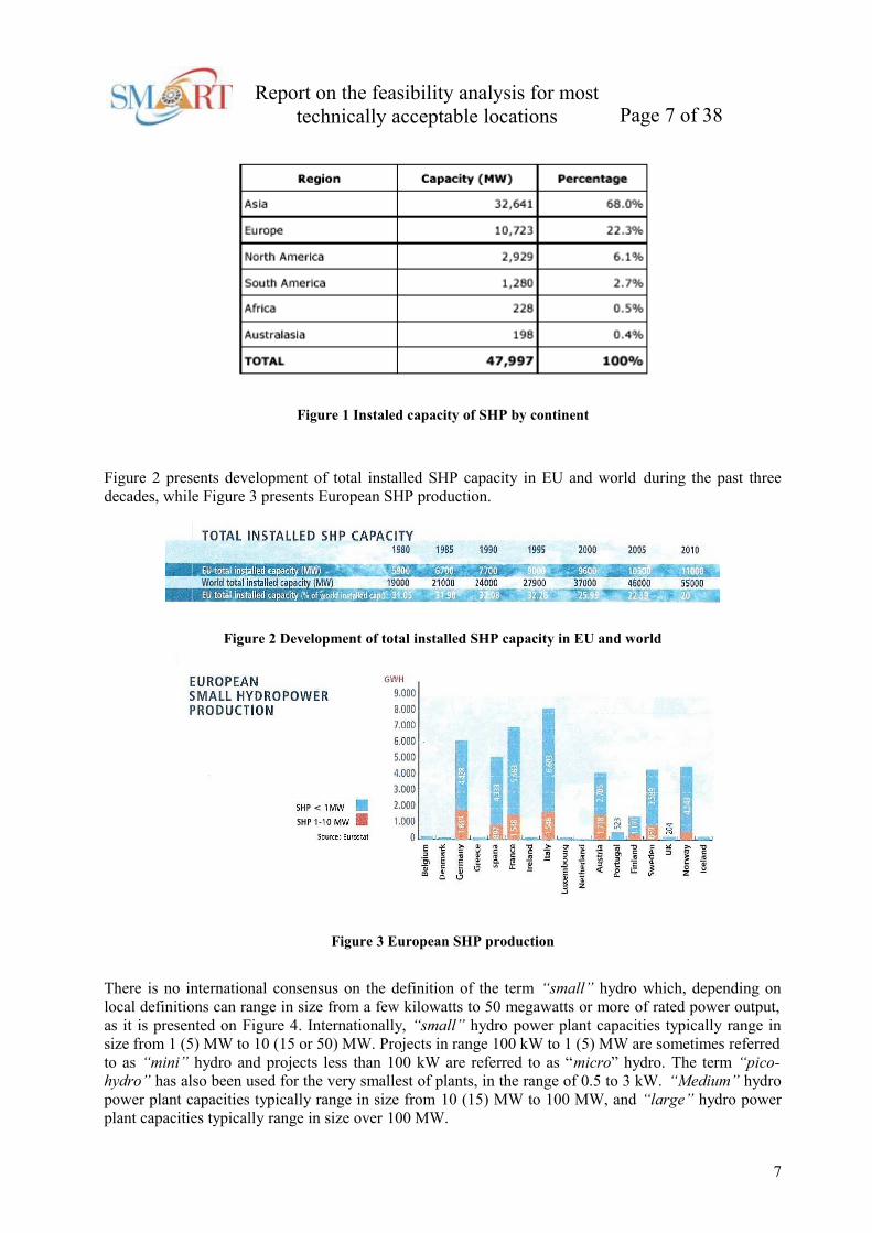
production and communication. The contribution of small hydropower plants (SHP), defined as
hydropower projects having a capacity below 10 MW, to the worldwide electrical capacity was about
2% of the total capacity amounting to 48 GW as shown in Figure 1. In the global small hydropower
sector, China is the leader representing more than half of the world’s small hydro capacity with 31,200
MW of installed capacity in 2005.
6
Report on the feasibility analysis for most
technically acceptable locations Page 7 of 38
Figure 1 Instaled capacity of SHP by continent
Figure 2 presents development of total installed SHP capacity in EU and world during the past three
decades, while Figure 3 presents European SHP production.
Figure 2 Development of total installed SHP capacity in EU and world
Figure 3 European SHP production
There is no international consensus on the definition of the term “small” hydro which, depending on
local definitions can range in size from a few kilowatts to 50 megawatts or more of rated power output,
as it is presented on Figure 4. Internationally, “small” hydro power plant capacities typically range in
size from 1 (5) MW to 10 (15 or 50) MW. Projects in range 100 kW to 1 (5) MW are sometimes referred
to as “mini” hydro and projects less than 100 kW are referred to as “micro” hydro. The term “pico-
hydro” has also been used for the very smallest of plants, in the range of 0.5 to 3 kW. “Medium” hydro
power plant capacities typically range in size from 10 (15) MW to 100 MW, and “large” hydro power
plant capacities typically range in size over 100 MW.
7

Report on the feasibility analysis for most
technically acceptable locations Page 8 of 38
Pico-hydropower From 0.5 to 3 kW
Micro-hydropower < 100 kW
Mini-hydropower From 100 kW to 1 (5) MW
Small hydropowerFrom 1 (5) MW to 10 (15 or 50) MW
Medium hydropower From 10 (15 or 50) MW to 100MW
Large hydropower > 100 MW
Figure 4 Commonly accepted thresholds for hydropower systems
“Small hydro” and “low head hydro” are not synonomous. Low head hydro is a term associated with a
research and development programs which are designed to advance the technology for generating hydro
power from sites with heads of less than 20 meters.
Several types of studies varying in scope, detail and intended client are performed to determine the
desirability of implementation of hydropower proposals. This text has adopted the standard sequence of
preconstruction studies commonly followed in practice. They are “reconnaissance” or “prefeasibility”
(should a feasibility study be performed?), “feasibility” (should an investment commitment be made?),
and “definite plan” (the collective group of studies that are performed between an implementation
commitment and construction initiation that result in permit applications, preparation of marketing
agreements and financial arrangements, and definition of design parameters). The intention of the text is
to aid in the execution of the reconnaissance and feasibility studies. A reconnaissance study is defined as
…”a preliminary feasibility study designed to ascertain whether a feasibility study is warranted”, and
feasibility study as … “an investigation performed to formulate a hydropower project and definitively
assess its desirability for implementation”.
The reason underlying the major attention that is focused on small hydro is important in establishing the
conceptual base for establishing a feasibility methodology. The character of small hydro is such that the
marketable output will most often only be energy with little, if any, dependable capacity. This means the
value of small hydropower will be primarily due to fuel and other operating cost savings and not due to
offsetting the need for new power plants to supply capacity.
The feasibility of projects is expected to be quite sensitive to site specific conditions, e.g., the quantity of
power produced will not likely support an extensive array of ancillary features such as long
transmissions lines, access roads, or significant site preparation, etc. The nature of the market area load
characteristics and present generating facilities servicing the load are critical elements in valuing power
output. Areas served with major fossil fuel base plants or systems with high operating cost plants,
operating at the margin will be more attractive for small hydro development. A significant issue of
project feasibility is that investigation, design, construction management, administration and
contingencies (the non-hardware elements of a project) are a major cost burden. Figure 5 schematically
illustrates the cost elements in small hydro projects with high head, and Figure 6 the cost elements in
small hydro projects with low head.
8

Report on the feasibility analysis for most
technically acceptable locations Page 9 of 38
Figure 5 The cost elements in small hydro projects with high head
Figure 6 The cost elements in small hydro projects with low head
The development of small hydro power projects consist of three phases: prefeasibility study, feasibility
study and implementation. Here in the focus is feasibility study, but because of completeness and the
other two phases will be briefly presented. First, the single stages will be shown in general and then
specifically for mini hydro power plants (to 1 MW).
For a better understanding of the prefeasibility study, feasibility study and implementation phase issues,
in the text the next chapters are given: types of small hydro-power schemes, types of turbines,
governors, hydro-electric generators and civil works.
9

Report on the feasibility analysis for most
technically acceptable locations Page 10 of 38
1.2 Small hydro project development and operation phases
There are normally four phases for engineering work required to develop a hydro project:
1st - phase Reconnaissance surveys and hydraulic studies covers map studies; characterization of the
drainage basins; preliminary estimates of flow and floods; a short site visit; preliminary layout; cost
estimates based on experience and a final ranking of alternatives based on optimization of power
potential and initial estimated cost.
2nd phase Prefeasibility study includes site mapping and geological investigations (with drilling and
sampling); a reconnaissance for suitable borrow areas; a preliminary layout based on materials known to
be available; preliminary selection of the main project characteristics; a cost estimate based on major
quantities; and the identification of possible environmental impacts.
3rd phase Feasibility study includes the selected alternative with a major geographical investigation
program; delineation and testing of all borrow pits; estimation of design and probable maximum floods;
determination of power potential for a range of dam heights and installed capacities for project
optimization; determination of the project design earthquake; design of all structures in sufficient detail;
determination of the dewatering sequence and project schedule; optimization of the project layout, water
levels and components; production of a detailed cost estimate; and finally, an economic and financial
evaluation of the project along with a feasibility report.
4th phase Implementation (System planning and project engineering) includes final design of the
transmission system; integration of the project into the power network; production of tender drawings
and specifications; analysis of bids and detailed design of the project; production of detailed
construction drawings and review of manufacturer’s equipment drawings.
The other two phases are related with financial aspect of the project and the maintenance of the plant.
5th phase Financing is often difficult for small hydro projects. Firstly a contract has to be obtained with a
utility or organization which will purchase the produced electricity. With this contract in place the next
step is to negotiate a bank loan or other source of financing. However, many banks lack knowledge of
small hydro projects and have no experience with this type of loan. In recent years some banks have
acquired the necessary experience and now routinely provide loans for small hydro.
6th phase Ownership and maintenance, where are some important factors for the effective operation of a
small hydropower plant successfully depending on financial and management skills of the investor:
realistic assessment of project costs and benefits, personal and corporate financial strength,
knowledgeable financial institution, design with special attention of operation and maintenance
requirements and professional maintenance plan to minimize expense and downtime.
However, for small hydro, the engineering work is often reduced to three phases in order to reduce total
cost by combining the work involved in the first two phases described below and decreasing the level of
detail. Three distinct phases exist for the assessment of small hydro which includes a desktop
prefeasibility study (including reconnaissance surveys); feasibility study; and an implementation phase.
The prefeasibility phase is the concept stage which defines at a high-level the capacity, demand
estimation and community suitability. Assessing the water resource and obtaining all available existing
data and information is critical in assessing the certainty of the energy production potential.
10

Report on the feasibility analysis for most
technically acceptable locations Page 11 of 38
The feasibility assessment is a technical and commercial analysis which will allow the owner to decide
whether to proceed with implementation of the scheme. The feasibility study assessment should consider
as a minimum, a site inspection; hydrological modelling; field investigations; hydropower assessment;
social and environmental issues; preliminary design; costing and financial analysis.
This text provides technical data and procedural guidance for the systematic appraisal of the viability of
potential small hydropower additions and focuses upon the concepts, technology, and economic and
financial issues unique to these additions. The contribution, designed to aid in the performance of
prefeasibility studies i.e. reconnaissance studies (should a feasibility study be performed?) and
feasibility studies (should an investment commitment be made?), was developed for use by public
agencies (state and local), public and private utilities, and private investors.
The text includes data and discussions on the topical subjects of cost escalation in economic and
financial analysis, feature component selection for reconnaissance and feasibility levels of study, and
time, cost, and resources required to perform the investigations.
1.3 Types of small hydro-power schemes
Nearly a quarter of the energy from the sun that reaches the Earth’s surface causes water from the seas,
lakes and ponds to evaporate. A proportion of this energy is used to make water vapour rise, against the
gravitational pull of the Earth into the atmosphere, where it eventually condenses to form rain or snow.
When it rains in the hills or snows in the mountains, some of the solar energy input remains stored.
Therefore water at any height above sea level represents stored ‘gravitational’ energy.
Hydro energy is naturally dissipated by eddies and currents as the water runs downhill in streams and
rivers until it reaches the sea. The greater the volume of water stored and the higher up it is, then the
more available energy it contains. For example, water stored behind a dam in a reservoir contains
considerable ‘potential’ energy. To capture this energy in a controlled form, some or all of the water in a
natural waterway can be diverted into a pipe. It can then be directed as a stream of water under pressure
onto a water wheel or turbine wheel. The water striking the blades causes the wheel (or turbine) to turn
and create mechanical energy.
The hydro electric plants work by converting the kinetic energy from water falling into electric energy.
This is achieved from water powering a turbine, and using the rotation movement to transfer energy
through a shaft to an electric generator.
The Figure 7 illustrates a typical small hydro scheme on a medium or high head.
The scheme can be summarised as follows:
• Water is taken from the river by diverting it through an intake at a weir.
• In medium or high-head installations water may first be carried horizontally to the forebay tank
by a small canal or ‘leat’.
• Before descending to the turbine, the water passes through a settling tank or “forebay”in which
the water is slowed down sufficiently for suspended particles to settle out.
• The forebay is usually protected by a rack of metal bars (a trash rack) which filters out water-
borne debris.
• A pressure pipe, or “penstock”, conveys the water from the forebay to the turbine, which is
enclosed in the powerhouse together with the generator and control equipment.
11

Report on the feasibility analysis for most
technically acceptable locations Page 12 of 38
• After leaving the turbine, the water discharges down a “tailrace” canal back into the river.
Figure 7 Illustration of a micro hydroelectric system
In practice, sites that are suitable for small-scale hydro schemes vary greatly. They include mountainous
locations where there are fast-flowing mountain streams and lowland areas with wide rivers. In some
cases development would involve the refurbishment of a historic water power site. In others it would
require an entirely new construction. Figure 8 illustrates the four most common layouts for a mini hydro
scheme. A variation on the canal-and-penstock layout for medium and high-head schemes is to use only
a penstock, and omit the use of a canal. This would be applicable where the terrain would make canal
construction difficult, or in an environmentally-sensitive location where the scheme needs to be hidden
and a buried penstock is the only acceptable solution.
For low head schemes, there are two typical layouts. Where the project is a redevelopment of an old
scheme, there will often be a canal still in existence drawing water to an old powerhouse or watermill. It
may make sense to re-use this canal, although in some cases this may have been sized for a lower flow
than would be cost-effective for a new scheme. In this case, a barrage development may be possible on
the same site.
With a barrage development, the turbine(s) are constructed as part of the weir or immediately adjacent to
it, so that almost no approach canal or pipe-work is required.
A final option for the location of new mini-hydro turbines is on the exit flow from water-treatment
plants or sewage works.
12

Report on the feasibility analysis for most
technically acceptable locations Page 13 of 38
Figure 8 Most common layouts for a mini hydro scheme
1.3.1 Run of river
The first hydro facilities were known as run of river schemes. The schemes do not include any
significant water storage, and therefore make use of whatever water is lowing in the river. When streams
and rivers have low flow, run of river schemes are unable to generate power. A typical run of river
scheme involves either a low level diversion weir (a small dam) or a stream bed intake, and are usually
located on swift flowing streams. A low level diversion weir raises the water level in the river
sufficiently to enable an intake structure to be located on the side of the river. The intake consists of a
trash screen and submerged opening with an intake gate. An alternative arrangement is to have a
streambed intake where the water drops through a screened inlet duct that has been installed flush with
the bottom of the riverbed. A streambed intake will allow rocks and gravel to enter which means the
design must include a screen to flush out the debris in the system. Water from the intake is normally
taken through a pipe (penstock) downhill to a power house constructed downstream of the intake and as
at low a level as possible to gain the maximum head of the turbine. Figure 9 presents run of river
scheme.
13

Report on the feasibility analysis for most
technically acceptable locations Page 14 of 38
Figure 9 Run of river scheme
1.3.2 Dam based
Hydro schemes may also be based on the construction of a large dam to store water and to provide
sufficient head for the turbine. These water storage schemes enable the power station to generate at
times of peak power demand, and then allow the water level to rise again during off peak time. Schemes
with large dams are better suited to larger, gently graded rivers. The advantage of this type of plant is
that they have the capability to store the energy (water) and use it when necessary. Figure 10 presents
dam based scheme.
Figure 10 Dam based scheme
1.3.3 Pumped storage
14
Report on the feasibility analysis for most
technically acceptable locations Page 15 of 38
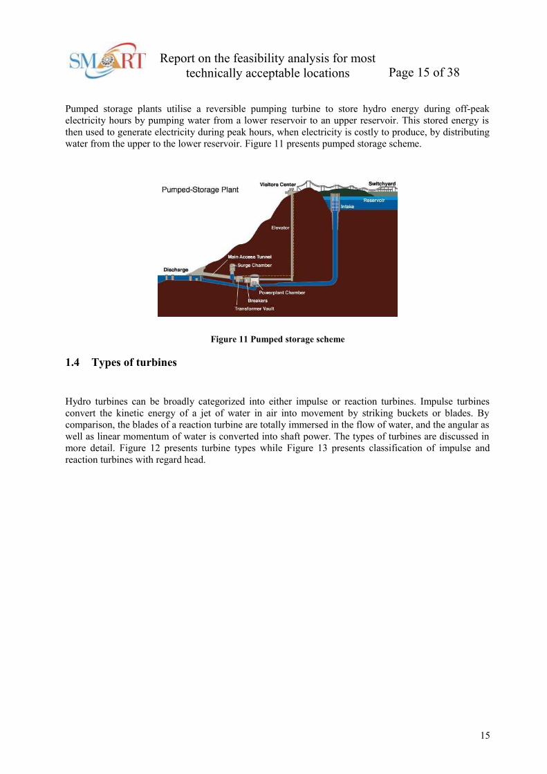
Pumped storage plants utilise a reversible pumping turbine to store hydro energy during off-peak
electricity hours by pumping water from a lower reservoir to an upper reservoir. This stored energy is
then used to generate electricity during peak hours, when electricity is costly to produce, by distributing
water from the upper to the lower reservoir. Figure 11 presents pumped storage scheme.
Figure 11 Pumped storage scheme
1.4 Types of turbines
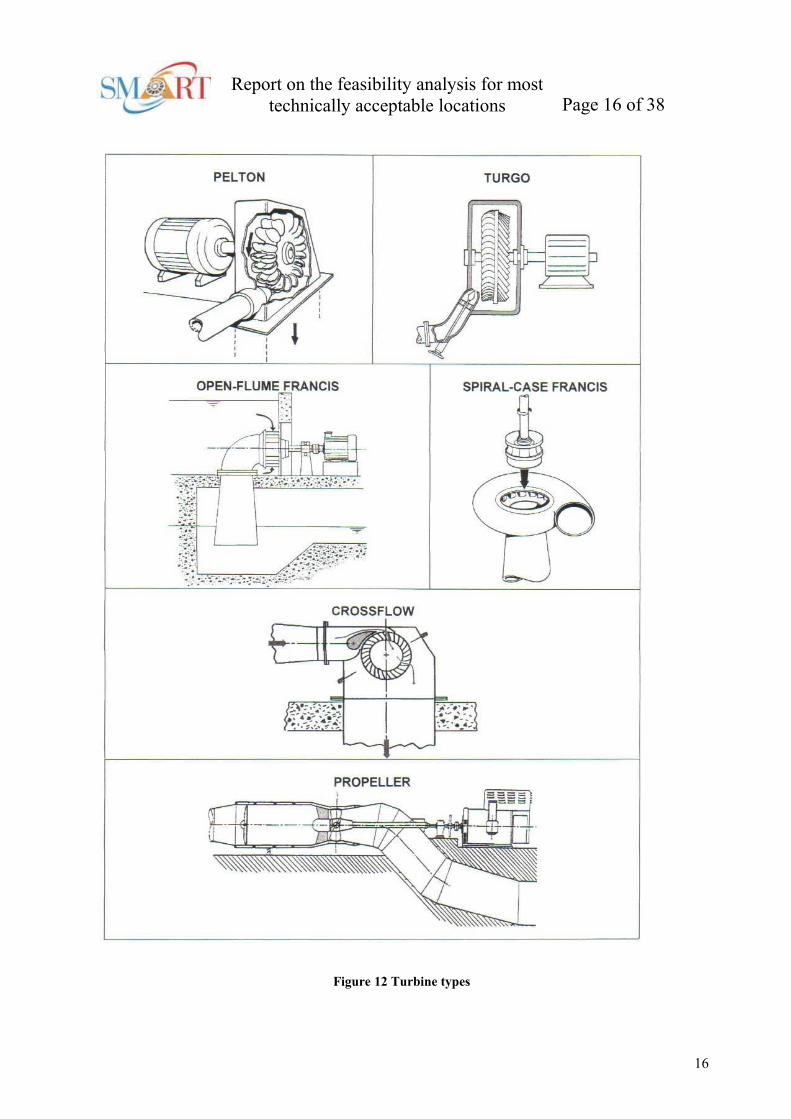
Hydro turbines can be broadly categorized into either impulse or reaction turbines. Impulse turbines
convert the kinetic energy of a jet of water in air into movement by striking buckets or blades. By
comparison, the blades of a reaction turbine are totally immersed in the flow of water, and the angular as
well as linear momentum of water is converted into shaft power. The types of turbines are discussed in
more detail. Figure 12 presents turbine types while Figure 13 presents classification of impulse and
reaction turbines with regard head.
15
Report on the feasibility analysis for most
technically acceptable locations Page 16 of 38
Figure 12 Turbine types
16

Report on the feasibility analysis for most
technically acceptable locations Page 17 of 38
Figure 13 Classification of impulse and reaction turbines with regard head
1.4.1 Pelton turbines
The Pelton wheel was developed in California during the Gold rush days of the 1850s. The Pelton
turbine consists of a set of specially shaped buckets mounted on a periphery of a circular disc. The disc
is turned by jets of water, which are discharged from one or more nozzles, striking the buckets, Figure
14. The buckets are split into two halves so that the central area does not act as a dead spot incapable of
deflecting water away from the oncoming jet. The cutaway on the lower lip allows the following bucket
to move further before cutting off the jet, propelling the bucket ahead of it, and also permits a smoother
entrance of the bucket into the jet. The Pelton bucket is designed to deflect the jet through 165 degrees
(not 180 degrees which is the maximum angle possible without the return jet interfering with the
following bucket for the oncoming jet).
Figure 14 Pelton turbine
In large scale hydro Pelton turbines are normally only considered for heads above 150 m, but for micro-
hydro applications Pelton turbines can used effectively at heads down to about 20 m. Pelton turbines are
not used at lower heads because their rotational speed becomes very slow and the runner required is very
large and unwieldy. This is an efficient process of extracting energy from the flow of water (90%) when
there is a very high head available.
17

Report on the feasibility analysis for most
technically acceptable locations Page 18 of 38
1.4.2 Turgo turbines
The Turgo turbine (Figure 15) is similar in design to a Pelton turbine, but was designed to have a higher
specific speed. In this case, the jets are aimed to strike the plane of the runner on one side and exit on the
other. Therefore the flow rate is not limited by the discharged fluid interfering with the incoming jet (as
is the case with Pelton turbines). As a consequence, a Turgo turbine can have a smaller diameter runner
than a Pelton for equivalent power. The Turgo is efficient over a wide range of speeds and shares the
general characteristics of a Pelton turbine including the fact that it can be mounted either horizontally or
vertically. A Turgo runner is more difficult to make than a Pelton and the vanes of the runner are more
fragile than Pelton buckets. They require about the same heads as do the Peltons and they sometimes
employ multi jets to allow them to accommodate more water flow.
Figure 15 Turgo turbine
1.4.3 Crossflow turbines
A crossflow turbine has a drumshaped runner consisting of two parallel discs connected together near
their rims by a series of curved blades. A cross flow turbine always has its runner shaft horizontal
(unlike Pelton and Turgo turbines). In operation a rectangular nozzle directs the jet onto the full length
of the runner. The water strikes the blades and imparts most of its kinetic energy. It then passes through
the runner and strikes the blades again on exit (Figure 16) impacting a smaller amount of energy before
leaving the turbine. At low flows, the water can be channelled through either two thirds or one third of
the runner, thereby sustaining relatively high turbine efficiency.
18

Report on the feasibility analysis for most
technically acceptable locations Page 19 of 38
Figure 16 Crossflow turbine
1.4.4 Francis turbines
The Francis turbines (Figure 17) may be divided in two groups; horizontal and vertical shaft. In practice
turbines with comparatively small dimensions are arranged with horizontal shaft, while larger turbines
have vertical shaft. Francis turbines can either be volute-cased or open-flume machines. The spiral
casing is tapered to distribute water uniformly around the entire perimeter of the runner and the guide
vanes feed the water into the runner at the correct angle.
Figure 17 Francis turbine
The Francis turbine is generally fitted with adjustable guide vanes. The runner blades are profiled in a
complex manner and direct the water so that it exits axially from the centre of the runner. In doing so the
water imparts most of its pressure energy to the runner before leaving the turbine via a draft tube. The
Francis turbine has the widest range of application among the various types of turbines available. Highly
flexible, it comes in a range of different sizes that can operate under heads ranging from around 20 to
500 meters.
19
Report on the feasibility analysis for most
technically acceptable locations Page 20 of 38
1.4.5 Propeller turbines
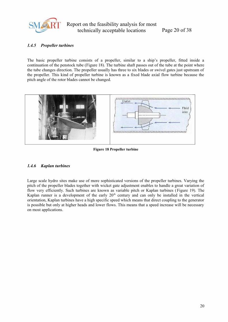
The basic propeller turbine consists of a propeller, similar to a ship’s propeller, fitted inside a
continuation of the penstock tube (Figure 18). The turbine shaft passes out of the tube at the point where
the tube changes direction. The propeller usually has three to six blades or swivel gates just upstream of
the propeller. This kind of propeller turbine is known as a fixed blade axial flow turbine because the
pitch angle of the rotor blades cannot be changed.
Figure 18 Propeller turbine
1.4.6 Kaplan turbines
Large scale hydro sites make use of more sophisticated versions of the propeller turbines. Varying the
pitch of the propeller blades together with wicket gate adjustment enables to handle a great variation of
flow very efficiently. Such turbines are known as variable pitch or Kaplan turbines (Figure 19). The
Kaplan runner is a development of the early 20 th century and can only be installed in the vertical
orientation, Kaplan turbines have a high specific speed which means that direct coupling to the generator
is possible but only at higher heads and lower flows. This means that a speed increase will be necessary
on most applications.
20

Report on the feasibility analysis for most
technically acceptable locations Page 21 of 38
Figure 19 Kaplan turbine
1.4.7 Bulb turbines
Bulb turbines are named after the shape of their upstream watertight enclosures. The generator is
accommodated within the enclosure and therefore submerged in the water passage (Figure 20). Suitable
for low heads and large discharge/head variations, bulb-units have virtually replaced Kaplan turbines for
very low heads sites. This is because the near straight design of the water passage improves the
hydraulic characteristics of the flow, giving both size and cost reductions. The bulb turbines have been
utilised however, more widely, in tidal power installations such as La Rance in France. For very low
heads, generator speeds have to be increased by means of gears.
Figure 20 Bulb turbines
1.4.8 Turbine selection chart
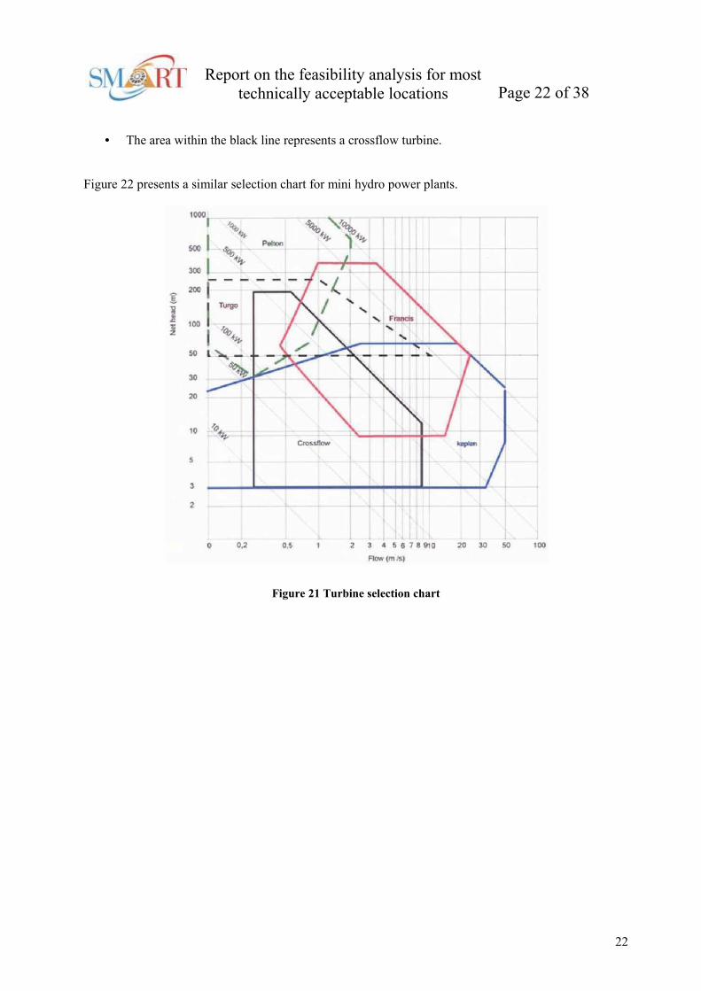
The turbine selection chart below (Figure 21) permits the user to select turbines for a given flow rate
(m3/s) and head (m):
• The area within the blue line represents a Kaplan or Bulb turbine;
• The area within the red line represents a Francis turbine;
• The area within the green line represents a Pelton turbine;
• The area within the dark dashed line represents a Turgo turbine;
21
Report on the feasibility analysis for most
technically acceptable locations Page 22 of 38
• The area within the black line represents a crossflow turbine.
Figure 22 presents a similar selection chart for mini hydro power plants.
Figure 21 Turbine selection chart
22
Report on the feasibility analysis for most
technically acceptable locations Page 23 of 38
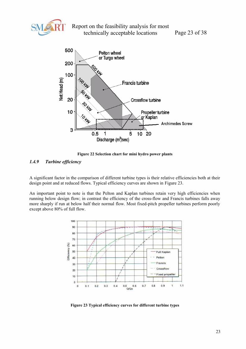
Figure 22 Selection chart for mini hydro power plants
1.4.9 Turbine efficiency
A significant factor in the comparison of different turbine types is their relative efficiencies both at their
design point and at reduced flows. Typical efficiency curves are shown in Figure 23.
An important point to note is that the Pelton and Kaplan turbines retain very high efficiencies when
running below design flow; in contrast the efficiency of the cross-flow and Francis turbines falls away
more sharply if run at below half their normal flow. Most fixed-pitch propeller turbines perform poorly
except above 80% of full flow.
Figure 23 Typical efficiency curves for different turbine types
23

Report on the feasibility analysis for most
technically acceptable locations Page 24 of 38
1.5 Governors
Turbine governors are equipment for rapid control and adjustment of the turbine power output and
evening out deviations between power and the grid load. The governor system can be mechanical-
hydraulic, electro-hydraulic, or digital hydraulic. The systems, regardless of type have the following
three components:
• The controller, which is the unit used for control of the hydro installation;
• The servo system, which is an amplifier that carries out water, admission changes determined by
the controller;
• The pressure oil supply system, which is used to supply oil to the servo system.
The turbine governors purpose is to keep the rotational speed of the turbine generator stable at any grid
load and water flow in the turbine conduit. During load rejections or emergency stops the turbine water
admission must be closed down according to acceptable limits of the rotational speed rise of the unit and
the pressure rise in the water conduit.
Figure 24 Governor function
Figure 24 shows the function of the governor. The input reference signal compared with the speed
feedback signal. With a momentary change in the load a deviation between the generator power output
and load occurs. The deviation causes the unit inertia masses either to accelerate or to decelerate. The
output of this process is the speed, which is again compared with the reference.
1.6 Hydro-electric generators
1.6.1 Synchronous generators
A synchronous generator can be connected to a small hydro turbine and can operate either connected to
the grid or as a stand-alone generator. The generator operates at a speed directly related to the frequency.
However, when the small hydro turbine is connected to a synchronous generator, which is directly
connected to the electric grid, a speed variation is not possible. If speed variation is not possible, system
efficiency is reduced because the generator cannot adapt to a partial load. There are also safety issues
24

Report on the feasibility analysis for most
technically acceptable locations Page 25 of 38
with synchronous generators which include; voltage regulation, islanding, and speed and frequency
control.
1.6.2 Induction generators
Induction generators rely on a connection to an outside source of power, i.e. the electricity network, to
establish and control the rotating magnetic field. This makes this type of generator a safer option than
other types of generators for connection to the grid. However, in the absence of grid connection it is
possible for induction generators to generate power if it is connected to a sufficient source of
capacitance reactance, such as capacitors. In this case very high voltages will be produced, causing a
hazard to the equipment.
1.7 Civil works
1.7.1 Dams
Dams are classified according to their profile and building material, which is typically concrete, earth or
rock. The civil works for a hydro electric scheme typically accounts for 60% of a plant’s initial
investment.
1.7.2 Concrete dams
Concrete dams can be divided into solid gravity, hollow gravity, and arch dams. The gravity dam relies
on its own weight to resist hydraulic thrust. The hollow gravity dam contains about 35% of the concrete
required for a solid dam, but is more expensive per unit volume. The arch dam, is designed for narrow
valleys and distributes the hydraulic thrust to its abutments.
1.7.3 Rockfill and earthfill
Rockfill and earthfill dams usually have a core which is covered with loose rock or earthfill. Grass may
even be grown on the earth fill. Water will seep in through the earth or rock fill, but should not seep into
the core.
1.7.4 Canals and channels
The canal conducts the water from the intake to the forebay tank. The length of the channel depends on
local conditions. Most canals and channels are excavated to reduce friction and prevent leakage,
channels are often sealed with cement, clay or polythene sheet. The size and shape of a channel are often
a compromise between costs and reduced head. As water flows in the channel, it loses energy in the
process of sliding past the walls and bed material. The rougher the material, the greater the friction loss
and the higher the head drop needed between channel entry and exit.
1.7.5 Settling basin
25

Report on the feasibility analysis for most
technically acceptable locations Page 26 of 38
The water drawn from the river and fed to the turbine will usually carry a suspension of small particles.
The sediment will be composed of hard abrasive particles such as sand which can cause damage and
rapid wear to turbine runners. To remove this material the water flow must be slowed down in settling
basins so that the silt particles will settle on the basin floor. The deposit formed is then periodically
flushed away.
1.7.6 Forebay tank
The forebay tank forms the connection between the channel and the penstock. The main purpose is to
allow the last particles to settle down before the water enters the penstock. Depending on its size it can
also serve as a reservoir to store water. A sluice will make it possible to close the entrance to the
penstock. In front of the penstock a trashrack is normally installed to prevent large particles entering the
penstock.
1.7.7 Penstock
The penstock is the pipe which conveys water under pressure from the forebay tank to the turbine. The
penstock often constitutes a major expense in the total micro-hydro budget, as much as 40% is not
uncommon in high head installations, and it is therefore worthwhile optimising the design. The trade-off
is between head loss and capital cost. Head loss due to friction in the pipe decrease dramatically with
increasing pipe diameter. Conversely, pipe costs increase steeply with diameter. Therefore a
compromise between cost and performance is required.
1.8 Prefeasibility (reconnaissance) study
1.8.1 Generally
The execution of a feasibility study can be a significant investment in time and resources suggesting that
a decision to proceed with a study should be based on a finding that a potentially viable project proposal
will be forthcoming. The reconnaissance (prefeasibility) study is designed to reduce the potential chance
of a subsequent unfavorable feasibility finding and maximize the potential for identifying and moving
forward the attractive projects. The prefeasibility study is a relatively complete small scale feasibility
study in which the issues expected to be important at the feasibility stage are raised. The finding of a
prefeasibility study should be either a positive recommendation to proceed with a feasibility study which
would include a study plan and method of accomplishment, or a recommendation to terminate further
investigations.
1.8.1.1 Project formulation
The strategy for performing a prefeasibility study is first to perform a preliminary economic analysis and
than identify and assess the issues that may be critical to implementation. The formulation of project
features and determination of costs was determined to be a critical and major task. The recommended
project formulation strategy is to select several installed capacities, say at 15%, 25% and 35% flow
exceedance values, and carry these through the preliminary economic analysis. The procedures
developed for performing the cost estimates for construction, site acquisition, operation and
maintenance, and engineering and administration for the feasibility study were judged to be too detailed
for a reconnaissance (prefeasibility) study. To facilitate reconnaissance estimates, the information for the
26

Report on the feasibility analysis for most
technically acceptable locations Page 27 of 38
feasibility analysis was consolidated into one chart and table. Figure 5 and Figure 6 provides a basis for
estimating the major share of construction costs for items that are governed by capacity and head, e.g.,
turbine and generator, powerhouse, and supporting electrical/mechanical equipment. The figure was
developed by studying the generator and powerhouse costs for variety of turbine types for a complete set
of head/capacity values. Reconnaissance costs factors for penstock, tailrace, switchyard equipment, and
transmission line is possible determine from literature. The user is cautioned that the least cost criteria
governed so that site issues of space and configuration, and generation issues of performance ranges
were not considered. The data, however, should be adequate for reconnaissance estimates. An additional
allowance of up to 20% should be added to the cost determined to cover investment items that are not
incorporated in the chart and table such as land acquisitions, access roads, and special control
equipment.
Since reconnaissance cost estimates are also needed for the nonphysical works cost items, an allowance
for unforeseen contingencies ranging from 10% to 20% be added to the sum of the construction cost, the
value depending upon a judgement as to the uncertainties. Indirect costs of 25% are recommended to be
added for investigation, management, engineering, and administration costs that are needed to
implement the project and continue its service. Operation and maintenance costs can vary considerably
depending on present staff resources of the project proponent, the site proximity to other sites, and the
intended degree of on-site operation requirements. An annual value of 1.5% of total costs is suggested as
a base value; however, the value used should not be less than a base value, and may range upwards of
4% if the project proponents can not efficiently integrate the plant into their work program.
1.8.1.2 Power values
The determination of value of power is an very important item. The power value needed is the value that
the project proponent could reasonably expect to receive for the sale of the generated energy and that of
the dependable capacity, if any exists.
1.8.1.3 Economic feasibility
Economic feasibility is positive when the benefits exceeds the costs. The text encourages adoption of the
Internal Rate of Return method of characterizing project feasibility. The Internal Rate of Return is
discount rate at which the benefits and costs are equal, e.g., the discount rate at which the benefit to cost
ratio is unity. Use of the method avoids the need at the reconnaissance stage to adopt a discount rate and
also provides an array of economic feasibility results. To perform the analysis several discount rates are
selected and the total investment cost in annualized for each rate and added to the annual operation and
maintenance cost to obtain the total annual cost. The benefit is computed on an annual basis by
multiplying the yearly generation by the value of energy. A benefit to cost ratio is determined for each
total annualized cost which is than plotted relative to its respective discount rate. A curve is drawn
connecting the plotted points and the Internal Rate of Return is the discount rate where the curve
intersects the line representing a benefit to cost ratio of unity (see example).
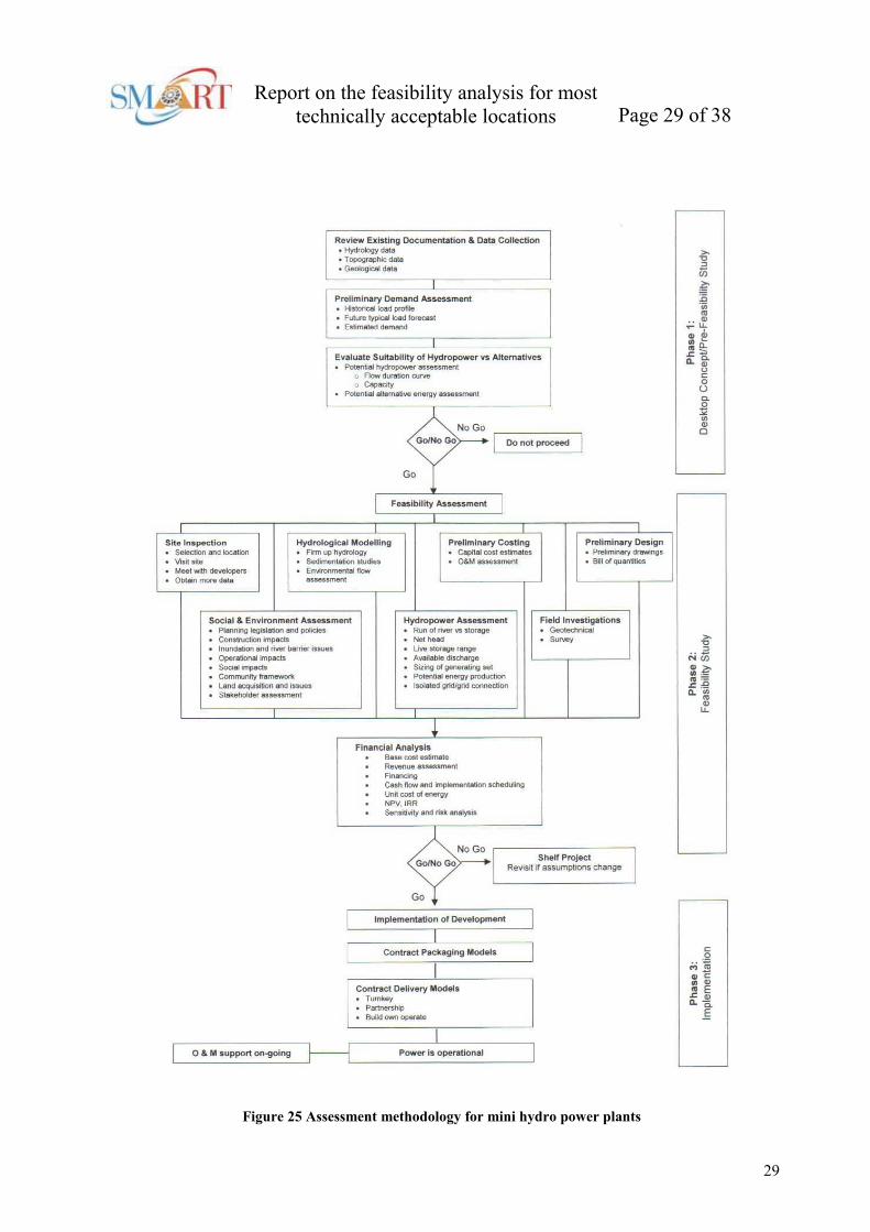
1.8.2 Specificity of mini hydro power project
The activities required during prefeasibility (reconnaissance) study of mini hydro power project
proposed by Hydro Tasmania are given in the flowchart presented on Figure 25.
27

Report on the feasibility analysis for most
technically acceptable locations Page 28 of 38
1.8.2.1 Review of Existing Documentation & Data Collection
As a first step to understanding the issues associated with developing hydropower, a review of relevant
documentation is required to be undertaken. To be able to perform a desktop study of the hydropower
development all relevant existing information relating to the scheme must be obtained, in particular,
hydrological data, topographic data and geological data. Assessing the available water resource is a key
part of the project, and the certainty of the energy production potential and price estimates relies on its
accuracy.
Hydrological Data Review Measured hydrological flow data or stream gauging information located on
the catchment in question should be utilised. The most accurate data would include the finest time series
and the longest period of data. A minimum of 1 years daily flow data is required to make a preliminary
assessment. Where no measuring site exists or hydrological data is limited, flow and rainfall information
data for an adjacent (or similar) catchment maybe used, and adjusted for catchment area and average
rainfall level. Given the similar nature of the topography, mean annual rainfall and catchment areas it
would be expected that the flow duration curves for these catchments would be similar. This provides
some uncertainty in the results, but will be sufficiently accurate for the purpose of a prefeasibility
assessment. It is advisable to follow this up with site measurement once the project looks likely to be
feasible.
Topographic Data Review In the absence of detailed information, topographic maps should be used for
contour information and to determine catchment areas and land use. Contour information or aerial
photographic maps with reasonable accuracy (1:25,000) should be obtained for determining levels and
distances. Levels or spot height information will need to be verified by a detailed survey at the
feasibility stage.
Geological Data Review An assessment of the regional geology by means of geological maps and
review of existing reports should be made to assess the potential location and scheme arrangement. In
particular consideration should be given to ground conditions, landslides, regional seismic activity and
river sedimentation loads. These features may directly influence the design of penstocks and tunnels; the
design of the intake structure to be able to cope with high sediment loads or the height of weirs
associated with intake structures.
1.8.2.2 Preliminary demanda assessment
It is important to determine the ability of the generated electricity to be used within the region or the
need to supply nearby loads (e.g. communities, industry) as this will influence the feasibility of the
scheme. Assessment of historical and present electrical demand should be made based on the best
available information. This will allow a typical load profile to be determined, which will show energy
supplied and the historical trending, system losses and any variance with the expected system losses.
Consideration of future maximum demand forecasts should be made by understanding if any firm plans
exist to increase loads. (e.g. best knowledge of industrial and commercial developments).
1.8.2.3 Evaluate suitability of hydropower Vs alternative
It may be necessary to consider alternative energy generation compared to hydropower to determine the
most economically and technically viable scheme. By assessing alternative options at a pre-feasibility
level, a well-rounded opinion of the power generation available can be made. The energy generation
options should be ranked by a project screening exercise, and selection criteria developed to determine
the commissioning of a feasibility study. Capacity, demand estimation, community suitability and cost
performance issues should be used for the optimisation and selection.
28
Report on the feasibility analysis for most
technically acceptable locations Page 29 of 38
Figure 25 Assessment methodology for mini hydro power plants
29

Report on the feasibility analysis for most
technically acceptable locations Page 30 of 38
1.9 Feasibility study
1.9.1 Generaly
The feasibility study is designed to formulate a viable small hydro project, develop an implementation
strategy, and provide the basis for an implementation commitment. The addition of small hydropower
generation to an existing facility is, with few exceptions, a single purpose project planning task. The
significant legal, institutional, engineering, environmental, marketing, economic and financial aspects
are to be identified, investigated, and definitively assessed in support of an investment decision. The
objective is to formulate a power addition project that is economically attractive and consistent with
modern concepts of resource planning and management. The findings of a feasibility study should be
whether or not a commitment to implementation is warranted, and should the finding be positive, define
the steps needed to assure implementation.
The selection of the installed capacity, the number of units, and the supporting ancillary physical works
are the specific objective of project formulation. The target of small hydro project formulation is to
develop one or more proposals that have the greatest economic value consistant with the array of
constraints that modify the attractiveness of a purely economic formulation. Two issues were singled out
for expanded discussion in the feasibility study section of the manual. They were refinement of
alternatives and development of costs for both the economic and financial analysis.
1.9.1.1 Refinement of alternatives
The significant interacting factors in the formulation of a small hydro project are the nature of flow/head
availability, the performance characteristics of the turbine equipment, and the powerhouse structure
needed to accommodate the specific generating equipment. The amount of energy that can be generated
is dependent upon the range of flow that can be passed through the turbine and upon the head variation.
The range of flow that can be utilized is therefore a function of the installed capacity, type of turbine
(operating range and efficiency characteristics), and number of units. Each of these variables affects the
size and shape of the powerhouse.
A project formulation strategy that progresses through three progressive stages of feature sizing and
selection is suggested. The first stage, essentially performance of a reconnaissance formulation is
discussed previously, yields a preliminary estimate of the project installed capacity. The second stage
incorporates machine performance characteristics in the formulation of several refined alternatives and
yields a selection of the number and type of turbine units that thus consider site conditions and tradeoffs
between unit performance and energy generated. The final stage concludes the project formulation by
examining the performance of the more promising one or more alternatives in a sequential power
routing analysis.
Hydrologic parameters play an important part in refinement of alternatives. Initially and during the first
stage, and perhaps the second, flow-duration techniques are judged to be generally adequate. Duration
curve analysis requires the use of a single value (weighted) for head and a single value (average) for
efficiency. Refinement occurs with the use of a continuous record of stream flow and performance of
sequential power routings. This procedure assures that important sequential issues of varying upstream
and downstream water levels, machine performance, and flow passage by the site are properly
incorporated in the analysis. The more complete simulation will trace the turbine performance and may
result in slightly higher or lower power and energy output estimates. The array of refined project
formulations are then subjected to full feasibility analysis.
30

Report on the feasibility analysis for most
technically acceptable locations Page 31 of 38
1.9.1.2 Economic analysis cost consideration
In the manual, economic and financial analysis have been carefully defined as having distinctly different
purposes, and consequently, distinctly different (although very much similar) cost data. Economic
feasibility analysis compares economic costs with project economic benefits while financial feasibility
analysis develops the specific cash flow and assesses financing and repayment issues. The economic
comparison is properly made using a common value base, (e.g., dollar values as of the study year).
Government policies have generally resulted in fixing price levels for valuing future costs and benefits
in value terms as of the study date as well and the time frame commonly used for cost/benefit analysis
begins the first year of project operation and extends through the project economic life. The alternative
convention often adopted in the private sector is to state all project costs and benefits in dollar values as
of the initial year of operation. Since small hydro project are expected to be implemented in short time
frames, the time and year statement of dollar values should not be critical.
The inclusion of cost and value changes in economic feasibility analysis must be handled with care. In
principle, a price level change economic analysis should forecast the change in value for all aspects of
the feasibility assessment, both the cost side and its several components. The cost and benefit streams
are then constructed from these forecasts and the feasibility assessment performed. The usual result of
including cost and value escalation in project as small hydro (large initial cost followed by small O&M,
and long stream of project benefits) is to make them appear more economically attractive, e.g., benefits
grow with time while costs increase slightly based on O&M. The impetus for including value changes is
the conviction that benefits will continue to rise knowing that some benefit elements are increasing more
rapidly than the general inflation rate, e.g., fossil fuel costs. The argument is that ignoring these value
shifts leads to incorrect decisions, (e.g., the project may appear infeasible when it should be found to be
feasible) even though theoretically, inclusion of general price rise (inflation, not differential cost
escalation) does not affect the feasibility determination.
The argument against including price level change and/or general cost escalation in economic feasibility
analysis is that change in price forecasting is fraught with pitfalls that are both institutionally and
technologically dependent. The resulting analysis thus often becomes suspect and a candidate for
subjective manipulation, i.e., a means of justifying projects. If cost and value change analysis are
adopted for the economic analysis, considerable care should be taken to rigorously observe the basic
principles and to document the critical value change forecast.
1.9.1.3 Financial analysis cost considerations
Financial feasibility analysis develops, among other data, the specific cash flow characteristics (dollars
in and out of the accounts) of the project. The need is to forecast the amount and timing of cash outflow
and revenue income as accurately as possible. The cash flow analysis is usually constructed for the
project implementation period, the first year of operation often being critical to project cash reserves. To
perform the analysis, the construction costs are indexed to the actual date of contract award; interest
during construction is added along with recurring costs (operations and maintenance) escalated based on
increased costs to service again equipment and on anticipated general cost inflation; and the revenue
stream is adjusted based on anticipated power sale contract provisions for payment of project power. If
there were no cost inflation, no borrowing required, and if project revenues captured all project benefits
exactly, the economic cost and benefit streams and the financial cost and revenue cash flow streams
would be identical.
31

Report on the feasibility analysis for most
technically acceptable locations Page 32 of 38
1.9.2 Specificity of mini hydro power project
The activities required during feasibility study of mini hydro power project proposed by Hydro
Tasmania are given in the flowchart presented on Figure 25.
A feasibility study assesses in detail the technical and economic viability of a small hydropower
development, and allows the client to determine whether to proceed with the implementation of the
scheme. The approach to this phase should include confirmation of data to be accurate and a detailed
assessment and optimisation of the costings. The essential components of a feasibility study are the next.
1.9.2.1 Site inspection
A site inspection should be carried out by a hydropower engineer for familiarisation of the environment
and determination of any major impediments to the implementation of the scheme. The engineer should
meet with client and operational representatives to obtain the best knowledge available and identify
further data input requirements.
An assessment of the following should be made while visiting site:
• Existence of a suitable energy resource. i.e. consistent flow of water at a usable head;
• Existing infrastructure and condition, including operational considerations;
• Potential intake and powerhouse location;
• Potential access road routes and suitable construction and equipment installation;
• A nearby demand for electricity, or the prospect of a grid connection at reasonable cost;
• The social and environmental impact/benefits on the local area;
• Land ownership and/or the prospect of land acquisition or lease;
1.9.2.2 Hydrological modelling
Confirmation of accurate hydrology and detailed modelling should be made to confirm the flow duration
curve. Long-term records of flow data and rainfall, together with an estimation of the
compensation/environmental flow (if required) should be assessed. Assessment of seasonal variation and
peak and off-peak demands need to be considered. A firm capacity of the scheme should be determined,
based upon the 90th percentile flow. The hydrological modelling may need to consider sedimentation
studies, especially concentration rates to assist with the design of the intake arrangement and location.
1.9.2.3 Field investigations
Dependent on the topographic data obtained in the prefeasibility study, it may be necessary to conduct a
topographic survey to confirm the net head of the scheme. Survey of the potential location of the intake
structure and powerhouse should be conducted, with spot heights recorded. This is particular important
for low head schemes when a reasonable amount of confidence is required for the level of accuracy of
the net head. Geotechnical boreholes will be required to finalize the location of the intake structure,
powerhouse and associated infrastructure and to allow input into the final design drawings.
1.9.2.4 Hydropower assessment
Since the flow and head data has now been confirmed the potential annual energy generation can be
properly assessed. Firstly the turbine and generator will need to be carefully selected and sized based
upon the suitability of the flow and head range. Optimisation of the operating range of the turbine will
need to be made, including the capacity factor of the scheme. There is clearly a balance to be stuck
between choosing a larger, more expensive turbine which takes a high flow but operates at a low
capacity factor, and selecting a smaller turbine which will generate less energy over the year, but will be
32

Report on the feasibility analysis for most
technically acceptable locations Page 33 of 38
utilised more of the time. i.e higher capacity factor. The capacity factor for most small hydro schemes
would normally fall within the range of 50% to 70% in order to provide a satisfactory return on
investment. Most turbines can operate over a range of flows (typically 30-40% of their rated flow) in
order to increase their energy capture and sustain a reduced output during the drier months. The
electricity generated by a scheme may be used at the point of generation or it may be exported via the
distribution network.
The hydropower assessment must define the average annual energy output (river flows, hydraulic losses,
operating head, turbine efficiencies and methods of calculations) (MWh/year) and the output of the
scheme in terms of maximum potential power output (MW).
1.9.2.5 Social and environmental
There are a number of environmental and social considerations that need to be investigated as part of the
feasibility study. It will include reviews and assessments of likely environmental impacts, broadly
considering factors such as:
• Assessment of any planning legislation and policies for the area;
• Requirements for clearing native vegetation;
• Impacts on stream flow and fish migration;
• Inundation or river barrier issues:
Threatened terrestrial species in inundation zone,
Fish migration barriers – migratory species can be an issue if they are regarded as a
threatened species, or locally important food source,
Operational impacts,
Community water supply,
Aquatic ecology health – environmental flows,
Hydropeaking issues – community safety, erosion potential,
Flood warning (gate operation if relevant, etc.),
Water quality in the reservoir,
Sedimentation of the reservoir and downstream;
• Construction impacts:
Traffic – road safety, noise, fuel spills,
Site runoff issues – siltation, construction noise, water quality,
Chemical/fuel spills,
Materials sourcing,
Water diversion issues;
• Social Impacts:
Potential for resettlement and relocation (to be avoided where possible),
Inundation of arable land,
Public safety,
Inundation of sacred sites/areas of cultural or historical value,
Stakeholder management.
Land issues and land compensation can be a major issue and will need to be carefully considered during
the study and could be a deciding factor in a recommendation.
33

Report on the feasibility analysis for most
technically acceptable locations Page 34 of 38
1.9.2.6 Preliminary design
The design of the scheme should be completed at a level adequate for costing and a bill of quantities to
be determined. Hence, the design should be adequate for tendering purposes, and would include general
arrangement and layout drawings.
Prominent aspects of the works can be categorised into:
• Civil works (intake and weir, intake channel, penstock, powerhouse, tailrace channel, site
access, construction details);
• Generating equipment (turbine, generator, control system);
• Network connection design to allow assessment of the local power distribution and the
community demand requirements.
Optimisation and design of the civil components (intake weir sizing; penstock sizing and lining;
minimising access routes and penstock lengths) will need to be finalised. In any small hydro scheme, the
electrical and mechanical components (ie. turbine, generator, control systems) determine the physical
arrangement of the powerhouse. The floor levels, roof clearance, building footprint, substructure
arrangement, pipework alignment and discharge arrangement are all dependent on the specific
characteristics of the selected equipment. If possible, the designers will therefore need to work closely
with the machinery suppliers, so that specific equipment parameters can be considered as the basis of the
design.
1.9.2.7 Costing
The costing of the scheme should include the costs to implement the project and the operation and
maintenance costs to allow its on-going operation. The capital cost estimate must be determined from
drawings and a bill of quantities as determined during the design phase. It should be at an accuracy in
the order of ±10%. Key capital cost items can be subdivided into:
• Cost of civil works;
• Cost of hydro-mechanical and electro-mechanical equipment;
• Cost of grid connection;
• Engineering and project management costs.
Capital Costs However, installed costs are only part of the overall life cycle costs, and the generating
profile (i.e. what proportion of time the turbine will operate for at full output and when) as well as the
ongoing maintenance, communications and electrical connections costs are core to the economics of
small hydro projects.
The civil costs may include the intake, forebay tank and screen, the penstock or channel to carry the
water to the turbine, the powerhouse and machinery foundations, the tailrace channel to return the water
to the river, and access roads. The civil works are largely site specific. On high head site the major cost
will be the penstock, on low head sites probably the water intake, screens and channel. The cost of
penstocks or tunnels has a significant impact on the overall cost of the scheme. Therefore penstock and
tunnel lengths should be kept as short as possible. The size of the powerhouse is generally proportional
to the machine diameter, which is related to the square root of the flow volume.
34

Report on the feasibility analysis for most
technically acceptable locations Page 35 of 38
Generally speaking, machinery costs for high head schemes are lower than for low head schemes of
similar power. High head machines have to pass less water than low head machines for the same power
output and are therefore smaller. They also run faster and thus can be connected directly to the generator
without the complication of gearbox or belts.
The electrical system will involve the control panel and system, the wiring within the powerhouse, and a
transformer if required, plus the cost of connection to the electricity. These costs are largely dependent
on the maximum power output of the installation. The connection cost is set by the local electrical
distribution company. A contingency of 20% of the construction cost was included in the final capital
estimates for each project.
Engineering and Project Management Costs These costs encompass the engineering services to design
and manage the installation, plus supervision costs for the project. This is likely to equate to
approximate 10 to 15% of the total capital amount. Land acquisition costs must be considered and
should be provided by the client where possible.
Operation & Maintenance Costs Operation and maintenance costs for small hydro turbines are low.
Generally, in developed countries, the stations are unmanned and automatically controlled by water
levels or from a central control room. Routine inspections are then required on a regular basis, and
generally in conjunction with other routine inspections. Generally, operation and maintenance costs for a
scheme may be up to 2% of the project capital cost.
1.9.2.8 Financial Assessment
A financial analysis will allow the economic viability of the project to be assessed. The analysis must
consider the following parameters as part of its economic modelling:
• Base cost estimate;
• Revenue assessment – the value of energy based upon market analysis or
• demand capability. Include seasonal variation and peak/off-peak pricing;
• Financing strategy;
• Cash flow analysis and implementation schedule;
• Economic life – typically 40 years used.
The economic viability should be presented by means of the unit cost of energy (EURO/kWh), net
present value and the internal rate of return. It is therefore likely that the client will have their own
hurdle rate in which the project must provide a minimum return for it to be considered eligible for
implementation. A sensitivity and risk analysis should be performed to test against the base case for
various changes in capital cost, revenue price and annual energy production. The risk assessment should
consider the project holistically including construction and operational considerations.
1.9.2.9 Criteria for decision
The feasibility study allows a detailed assessment of the technical and commercial viability of a scheme
to be made. However the decision whether to implement the scheme will be up to the owner, especially
if the scheme is economically marginal. The owner must fully understand their project and business
drivers, as the decision to implement may consider intangible benefits.
35

Report on the feasibility analysis for most
technically acceptable locations Page 36 of 38
An appropriate criterion for selection should consider:
• The scheme would need to be technically feasible, but of simple arrangement with appropriate
risk mitigation and containment in place;
• Easy to implement;
• Robust;
• Cost effective/cheap;
• Environmentally and socially sound and sustainable.
1.10 Time, cost and resources for prefeasibility (reconnaissance) and feasibility
studies
The time, costs and human resources required to perform prefeasibility (reconnaissance) and feasibility
studies for small hydroelectric power plant additions varies depending on expected plant size, site
conditions, specific scope and depth of study, and availability of information (basic data and prior
studies). Analysis of The American Society of Civil Engineers guidelines in light of recent feasibility
study experience suggest that feasibility study cost, noting the fairly specialized nature of several of the
issues important to small hydro, should range from 1.5% to 3% of estimated construction cost.
Prefeasibility studies, estimated as 10% of feasibility study costs, would therefore range from 0.15% to
0.3% of estimated construction costs. A prefeasibility study for a 1 MW plant might cost approximately
about 10-15 man-days. Using 2.5% as conservative estimate for feasibility study costs, for a 1 MW plant
might cost approximately about 80 to 110 man-days. The time required to perform the feasibility study
could range from 60 days for the small, relatively simple power addition to upwards of 6 to 9 months for
larger more complex projects.
The participating professionals for a feasibility study include civil, electrical and mechanical engineers,
power economists and especially for private proponent projects, the services of financial specialists.
Projects that significantly alter the flow regime or physical environment will likely need the services of
water quality and fish and wild life specialists. The participating professionals for a reconnaissance
study would likely include civil, mechanical and electrical engineer, and power economist for larger
proposed projects. Reconnaissance investigations of smaller projects may require more versatility in
fewer professional such as, experienced engineer and economist.
1.11 Implementation of development
The activities required during implementation of development of mini hydro power project proposed by
Hydro Tasmania are given in the flowchart presented on Figure 25.
Small hydropower development is of relatively complex nature that requires careful consideration of the
implementation process to ensure the development risk is effectively managed. The plant may be
embedded within local communities, which will require appropriate operational considerations and
constraints. Small hydro can often expose owners and developers to risks that far exceed the project’s
direct commercial indices due to the scale of the projects and their interaction with existing water assets,
electricity networks and control systems. While some schemes incorporate a degree of classic design,
most are born out of reinvested experience in the design and construction of similar schemes. Often the
adoption of arrangements to make use of existing structures and the careful consideration of operational
36

Report on the feasibility analysis for most
technically acceptable locations Page 37 of 38
flexibilities within the owner’s constraints can make the difference to commercial and technical
viability.
There are a number of development options, by means of contract packaging and delivery models which
can be adopted for the implementation of small hydropower. Each model has its own level of risk and
reward, which requires the developer to carefully consider the cost risk benefit of the development.
Design and construction risks must therefore for carefully managed to ensure risks are understood and
fully considered during construction and long-term operation.
1.11.1 Contract packaging models
The contract and commercial packaging for small hydro developments can be considered in a number of
ways. Given the need to manage the commercial conditions and the implementation timeframes, it is
important that the construction activities and procurement lead-times of equipment are fully understood.
Typically the critical path items are the procurement of the turbine and generator.
The contract can be packaged into a number of broad categories, such as:
• Civil package;
• Civil and hydromechanical package;
• Electrical and mechanical package;
• Grid connection package.
The interface or separation points need to be clearly defined to ensure appropriate delivery of design and
construction. The open tender process can involve extensive up-front engineering design and
specification works to allow all tenderer’s to compete on an equal basis, for a defined arrangement and
scope of work. Innovation in design would be offered through an alternative or nonconforming tender,
and in many cases this would prove successful in reducing the contract cost to allow the project to
remain economically viable. Pre-tender consultancies can cost in the order of 10-20% of the value of the
contract works for the smaller schemes, and while necessary to determine the feasibility of the scheme,
may add limited value to the tender process in achieving the most economical arrangement.
Often, the most economical schemes will be one where the supplier nominates their preferred equipment
and standards, and client requirements are then negotiated in. The supplier is in the best position to
know the level and standard of equipment required to perform the task, and often tender specifications
will only add to the expense of the equipment by specifying standards that may not be warranted by the
size of the installation. Some level of specification is always required to define what will finally be
delivered, performance criteria and standard of workmanship.
A more streamlined process for the procurement would be to obtain direct quotations from reputable
machine suppliers. Usually a maximum of three quotations would be sought, in order to select the most
suitable equipment supplier for the works, and that the intention of the design criteria is met. This would
also include an interview process of the preferred supplier. Final tender pricing will be prepared based
on the final design and outputs, including machine selection and pricing.
1.11.2 Contract delivery models
37

Report on the feasibility analysis for most
technically acceptable locations Page 38 of 38
Since any hydro scheme requires a substantial upfront investment, it is clearly essential that the project
is implemented correctly and with robust engineering and equipment. Generally, the delivery models for
the implementation can be categorised into:
• Turnkey (engineer, procure, construct);
• Partnership (joint venture/alliance);
• Build own operate.
Turnkey The most common approach for implementing small hydro projects is the turnkey contract in
which a single contractor takes the entire scheme from design to construction, which allows
simplification of the management of the project. The contractor, who might be a civil engineering
company or the turbine supplier, brings together a team of subcontractors and suppliers under a single
contract, typically following a competitive tendering process. Since the main contractor takes the full
risk, they have the opportunity to maximise the benefits and revenues.
Partnership Typically the owner enters into a partnership (alliance) arrangement with another developer
and the two parties combine their capabilities to best suit the project. This model ensures that the project
is delivered with shared risk and shared benefit.
Build own operate Under this model the owner sells all rights to the project, and a developer pays for the
rights and usually pays an annual royalty for its ownership. Hence, the developer takes the responsibility
of the full risk and benefits, in which the owner minimises their risk and benefit.
1.12 Literature
At writing of this chapter the next references were used:
[1] D. W. Davis, B.W. Smith, “Feasibility Analysis in Small Hydropower Planning”, US Army Corps of
Engineers – Hydrologic Engineering Center, 1979.
[2] G. Stojmirovic, T. Chu, “A Practical Guide to Assessment and Implementation of Small
Hydropower”, Hydro Tasmania Consulting, Tasmania.
[3] M. Tamburrini, “A Feasibility Study for a Micro-hydro Installation for the Strangford Lough
Wildfowlers & Conservation Association”, Master Thesis, University of Strathclyde, Glasgow, 2004.
[4] O. Korkmaz, “A Case Study on Feasibility Assessment of Small Hydropower Scheme”, Master
Thesis, Middle East Technical University, Ankara, 2007.
[5] “Terms of Reference for Preparation of Detailed Project Report – Inter Linking of Rivers”,
National Water Development Agency, Engineers India Limited.
[6] C. Dragu, T. Sels, R. Belmans, “Small Hydro Power – State of the Art and Applications”, K.U.
Leuven, Leuven, Belgium.
[7] “A Guide to UK Mini-hydro Developments”, The British Hydropower Association, 2005.
38