fd 150 document signer - formax 150 operator manual new.pdf · formax fd 150 document signer ......
TRANSCRIPT

FD 150Document Signer
OPERATOR MANUAL FIRST EDITION

1/97 02-0925-01
Thank you for purchasing the
Formax FD 150 Document Signer
The FD 150 has been tested and found to comply with the limits for a Class A digital device pursuant to Part 15 of FCC Rules. These limits are designed to provide reasonable protection against harmful interference when this equipment is operated in a commercial environment. This equipment generates, uses, and can radiate radio frequency energy and, if not installed and used in accordance with this manual, may cause harmful interference in which case the user will be required to correct the interference at his/her own expense. The FD 150 is UL listed.

Operating Manual
1/97 i
TABLE OF CONTENTS
1. INTRODUCTION ................................................................................................ 1.1 FD 150 DESCRIPTION .......................................................................................1 1.2 ITEMS INCLUDED................................................................................................1 1.3 OPERATING MANUAL SAFETY TERMS ..................................................................2 1.4 SAFETY PRECAUTIONS.......................................................................................3 1.5 FREQUENTLY-USED TERMS................................................................................3 1.6 LOG BOOK........................................................................................................4 1.7 SERVICE...........................................................................................................4 1.8 REPACKING INSTRUCTIONS ................................................................................5
2. SPECIFICATIONS............................................................................................6 2.1 SPECIFICATIONS................................................................................................6 2.2 OPERATING REQUIREMENTS...............................................................................6
3. ASSEMBLY......................................................................................................7 3.1 KEY POSITIONS .................................................................................................7 3.2 INK ROLL INSTALLATION .....................................................................................8 3.3 RECEIVING TRAY, TEMPORARY INSTALLATION......................................................9 3.4 RECEIVING TRAY, PERMANENT INSTALLATION....................................................10 3.5 OPTIONAL FEED TRAY EXTENSION....................................................................11
4. POWER CONNECTION .................................................................................12 4.1 SAFETY ..........................................................................................................12 4.2 LINE VOLTAGE ................................................................................................13 4.3 LINE FUSES ....................................................................................................14 4.4 POWER CORD .................................................................................................15
5. CONTROLS & INDICATORS.........................................................................16 5.1 COUNTER, NON-RESETTABLE ..........................................................................16 5.2 COUNTER, RESETTABLE ..................................................................................17 5.3 EXECUTIVE KEY ..............................................................................................17
5.3.1 Unlocked ...........................................................................................................................17 5.3.2 Locked...............................................................................................................................17
5.4 FEED ADJUST KNOB ........................................................................................17 5.5 IMPRINT INDICATOR .........................................................................................18 5.6 IMPRINT KEY ...................................................................................................18 5.7 INK ADJUSTMENT KNOB ...................................................................................18 5.8 IMPRINT POSITIONING ......................................................................................19
5.8.1 Light ON / OFF..................................................................................................................19 5.8.2 UP / DOWN.......................................................................................................................20
5.9 MEDIA FEED ...................................................................................................20

Operating Manual
ii 1/97
5.10 MEMORY IMPRINT POSITIONS .........................................................................21
5.10.1 Positions 1 - 4 .................................................................................................................21 5.10.2 Store Position..................................................................................................................21
5.11 PAPER WEIGHT .............................................................................................21 5.12 POWER SWITCH ............................................................................................22 5.13 READY INDICATOR .........................................................................................22 5.14 SEPARATORS ................................................................................................22
6. OPERATION...................................................................................................23 6.1 LOADING SADDLES ..........................................................................................23 6.2 LOADING DOCUMENTS .....................................................................................25 6.3 FEEDING DOCUMENTS .....................................................................................27 6.4 SETTING IMPRINT POSITION UP / DOWN..........................................................28
6.4.1 Imprint Position Example ..................................................................................................30 6.5 STORING AN IMPRINT POSITION........................................................................31
6.5.1 Sample Stored Imprint Positions.......................................................................................31 6.6 SETTING IMPRINT POSITION LEFT / RIGHT ......................................................32 6.7 IMPRINTING DOCUMENTS .................................................................................34 6.8 FEEDING VARIOUS SIZED DOCUMENTS..............................................................35
7. MAINTENANCE .............................................................................................36 7.1 PRESSURE TIRE SHAFT REMOVAL & INSTALLATION ............................................36 7.2 CLEANING.......................................................................................................37 7.3 REPLACING A FUSE.........................................................................................38
8. TROUBLESHOOTING ...................................................................................40 8.1 IMPROPER IMPRINTING.....................................................................................40
8.1.1 Double Feeding.................................................................................................................40 8.1.2 Executive Key Turned Too Quickly...................................................................................40 8.1.3 Imprint Is Too Light ...........................................................................................................41 8.1.4 Document Jam ..................................................................................................................42
8.2 TROUBLESHOOTING CHART..............................................................................42

Operating Manual
1/97 1
1. INTRODUCTION This manual shows you how to use the FD 150. It presents information about the FD 150’s specifications, physical features and operation.
1.1 FD150 Description
The FD 150 is a document imprinter used for signing, endorsing and validating cut-sheet documents. Documents to be imprinted are stacked in the feed tray. Two paper guides hold the stack in position as the documents are fed through the FD 150. The stack is separated into single pieces by separators and rolls which feed each document into the FD 150. A photosensor (an electric eye) in the base of the FD 150, senses the document and transmits this information to the microprocessor which controls the FD 150. The micro-processor directs a motor to rotate the saddle holder and imprint the document at the position set on the imprint position control. The imprinted documents then exit the FD150 and stack on the receiving tray.
1.2 Items Included The following items are shipped together in one box. Take note of each as you unpack the box.
• FD 150 • receiving tray • accessories carton • FD 150 Operating Manual • cloth bag (2 tray screws, 2 sets of keys and 2 knobs) • feed tray extension

Operating Manual
2 1/97
The accessories carton includes the following items:
• ink roll (with rubber gloves) • power cord • document stops (wrapped in foam) • log book • allen wrench • warranty cards
1.3 Operating Manual Safety Terms
The following highlighted blocks are used throughout this manual to emphasize important information. Pay very careful attention to this information.
WARNING USED TO ALERT YOU TO ACTIONS OR CONDITIONS WHICH MAY PRESENT HAZARDS OR CAUSE INJURY TO PERSONNEL.
CAUTION USED TO ALERT YOU TO ACTIONS WHICH MAY DAMAGE DOCUMENTS OR EQUIPMENT.
NOTE Used to identify unusual or unexpected conditions or to point out the need for alternate procedures. A NOTE may also be used for emphasis when a WARNING or CAUTION are not required.

Operating Manual
1/97 3
1.4 Safety Precautions
Please observe the following safety precautions and warnings at all times while operating, cleaning or repairing the FD 150. Failure to so may result in physical injury or damage to the FD 150. Neither Formax nor the manufacturer assumes any liability for your failure to comply with these requirements.
WARNING NEVER CLEAN, CLEAR OR DISASSEMBLE THE FD 150 WITHOUT FIRST UNPLUGGING THE POWER CORD.
WARNING KEEP LOOSE CLOTHING, TIES, SCARVES AND HAIR AWAY FROM ALL MOVING PARTS.
WARNING DO NOT PLACE FINGERS BETWEEN OR NEAR MOVING PARTS.
1.5 Frequently-Used Terms
leading edge The edge of the document that
enters and exits the FD 150 first.
trailing edge The edge of the document that enters and exits the FD 150 last.
imprint position The point at which the document is imprinted.
imprint saddle Contains a plastic relief of the imprint; 2 imprint saddles are in the rounded imprint saddle holder - as one is imprinting, the other is being inked.

Operating Manual
4 1/97
operator side The side of the FD 150 where most of the controls are located.
input end The end of the FD 150 where the document enters the FD 150.
output end The end of the FD 150 where the document exits the FD 150.
1.6 Log Book When used properly, the Log Book provides a written record of the number of documents imprinted. Keep the Log Book with the FD 150 whenever the machine is operating. Before imprinting new documents, record the number of imprints displayed on the non-resettable counter. After imprinting, record the new number displayed on the non-resettable counter.
1.7 Service If any problems occur with the FD 150 or if you need assistance installing or operating your FD 150, contact your Formax dealer.

Operating Manual
1/97 5
1.8 Repacking Instructions
If it is necessary to return the FD 150 to your Formax dealer, pack it in the original shipping container and material. If the original container is not available, the FD150 and its accessories should be carefully packed so that they will not be damaged in transit.
NOTE The Shipping Carrier is liable for any damages that may occur during shipping. Use the following instructions to pack the FD 150 with commercially available materials. 1. Double wrap the machine in plastic. 2. Use a heavy duty, double-walled container of 350-
pound test material. 3. Surround the FD 150 on ALL sides with at least 4 to 5
inches of shock absorbing packaging material. This will provide firm cushioning and prevent movement inside the container.
4. Seal the top and bottom of the shipping container with strong tape or banding.
5. Clearly and legibly mark the shipping container FRAGILE.
6. Ship the FD 150 prepaid and insured.

Operating Manual
6 1/97
2. SPECIFICATIONS This section contains specifications of the FD 150.
2.1 Specifications Size
19½" (49.53 cm) W x 10" (25.43 cm) H x 19" (48.26 cm) D The receiving tray is not measured.
Weight Machine alone: 50 pounds (22.68 kg ) Shipping weight: 57 pounds (25.85 kg)
Power Possible line voltages are 240V, 220V, 120V and 100V at 50-60 Hz
Speed 19" (45.72 cm) per second
2.2 Operating Requirements
Document Size
Maximum length: 14" (35.56 cm) Minimum length: 31/8" (10.92 cm) Maximum width: 14" (35.56 cm) Minimum width: 27/8" (7.3 cm) Weight: 20# - 125# stock
Range of Imprint Placement Approximately 9" (22.86 cm) from the leading edge
toward the trailing edge. Approximately 6½" (16.51 cm) left or right from the
center of the document.
Range of Accuracy ± 1/8"

Operating Manual
1/97 7
3. ASSEMBLY This section shows you how to assemble the FD 150.
WARNING
DO NOT PLUG THE FD 150 POWER CORD INTO AN ELECTRICAL OUTLET UNTIL ASSEMBLY IS COMPLETE AND YOU HAVE READ SECTION 4, POWER CONNECTION.
3.1 Key Positions Use the following instructions to open the FD 150 COVER. (Refer to Figure 3.1.)
Figure 3.1 -- Key Positions
1. Unlock the COVER by turning the brass EXECUTIVE
KEY to the UNLOCKED position. 2. Open the COVER.

Operating Manual
8 1/97
3.2 Ink Roll Installation
Use the following instructions to install the INK ROLL. (Refer to Figure 3.2.)
Figure 3.2 -- Ink Roll Installation
NOTE The FD 150 comes with one black INK ROLL. Formax offers a tri-color INK ROLL. To order INK ROLLS, call your Formax dealer.
NOTE Use care when handling the ink roll. The ink is indelible and will not wash out of clothing. 1. Turn the EXECUTIVE KEY to the UNLOCKED
position and open the COVER. 2. Pull out the COTTER PIN. 3. Pull out the AXLE. 4. Put on the gloves shipped with the INK ROLL.

Operating Manual
1/97 9
5. Hold the INK ROLL between the sides of the INK ROLL CARRIAGE.
6. Insert the AXLE, pointed end first, through the holes in the INK ROLL CARRIAGE and the INK ROLL.
7. Insert the straight side of the COTTER PIN into the hole in the pointed end of the AXLE.
8. Push the COTTER PIN until the AXLE is secured between the two loops on the COTTER PIN.
9. Close the COVER.
3.3 Receiving Tray, Temporary Installation
Use the following instructions to temporarily install the receiving tray. (Refer to Figure 3.3.)
Figure 3.3 -- FD 150 Receiving Tray Installation
1. Place the FD 150 on a table or work surface about 2"
from the straight edge. 2. Slide the NOTCHES in the tray up under the
MOUNTING STUDS on the output end of the FD 150.

Operating Manual
10 1/97
3. Re-position the FD 150 so the L-shaped cutout on each side of the RECEIVING TRAY fits the straight edge of the table or work surface. The RECEIVING TRAY will hang off the edge of the table or work surface.
3.4 Receiving Tray, Permanent Installation
1. Remove the MOUNTING STUDS with a 1/8" allen
wrench. 2. Place the FD 150 on a table or work surface about 2"
from the straight edge. 3. Place the NOTCHES in the RECEIVING TRAY
against the machine so they surround the holes left after the MOUNTING STUDS were removed.
4. Re-position the FD 150 so the L-shaped cutout on each side of the RECEIVING TRAY fits the straight edge of the table or work surface. The RECEIVING TRAY will hang off the edge of the table or work surface.
5. Screw the screws (included in the cloth bag) tightly into these holes.
6. Place the two straight DOCUMENT STOPS in-line with the PAPER GUIDES. (Refer to Figure 3.4.)
7. Position the curved DOCUMENT STOP so it stops and stacks exiting documents.
8. To extend the RECEIVING TRAY, pull the tray to the desired position or length.

Operating Manual
1/97 11
Figure 3.4 -- Paper Path & Document Stops
3.5 Optional Feed Tray Extension
The FEED TRAY EXTENSION which comes with the FD 150 is used to help feed documents longer than 9”. Keep it in a place you’ll remember, as you may need it in the future. Refer to Section 6.2 for installation details.

Operating Manual
12 1/97
4. POWER CONNECTION This section shows you how to connect power to the FD 150.
WARNING BEFORE PLUGGING THE FD 150 INTO AN ELECTRICAL OUTLET, CAREFULLY READ THE FOLLOWING INFORMATION ABOUT VOLTAGES, FUSES AND THE POWER CORD.
4.1 Safety The FD 150 can connect to any power distribution system, including the European IT Power System. Because the European IT Power System does not have a grounded neutral leg, the FD 150 uses protective fusing in both the neutral and hot supply lines of power. Both LINE FUSES must be in place for the FD 150 to operate properly.
WARNING A BLOWN FUSE IN THE NEUTRAL LEG COULD MEAN INTERIOR PARTS OF THE FD 150 REMAIN AT A HAZARDOUS VOLTAGE. ALWAYS UNPLUG THE POWER CORD BEFORE SERVICING THE FD 150.

Operating Manual
1/97 13
4.2 Line Voltage The FD 150 is rated for continuous operation using a variety of supply voltages. Possible line voltages are 240V, 220V, 120V and 100V at 50 to 60 Hz. The manufacturer configures the FD 150 to operate with the voltage requested by the customer.
CAUTION VERIFY THE CORRECT VOLTAGE SETTING BEFORE PLUGGING THE FD 150 INTO AN OUTLET. Read the selected voltage through the VOLTAGE SELECTOR WINDOW at the input end of the FD 150. (Refer to Figure 4.1.) To select a different voltage, use the following instructions:
NOTE The detachable POWER CORD may have to be changed to match the particular power-source output. 1. Unplug the POWER CORD. 2. Use a small screwdriver or similar tool to push up on
and release the FUSE DRAWER LOCKING TAB. 3. Pull the FUSE DRAWER out of the POWER ENTRY
CASING. 4. Pull the VOLTAGE SELECTOR out of the FUSE
DRAWER. 5. Rotate the VOLTAGE SELECTOR until the correct
voltage is on the same side as the VOLTAGE SELECTOR WINDOW.
6. Place the VOLTAGE SELECTOR in the FUSE DRAWER and verify the correct voltage selection.
7. Place the FUSE DRAWER in the POWER ENTRY CASING.

Operating Manual
14 1/97
Figure 4.1 -- FD 150 Power Connection
4.3 Line Fuses The FUSE DRAWER, located on the input end, contains two LINE FUSES. (Refer to Figure 4.1.) The neutral and hot lines of power are fused. Both LINE FUSES must be in place for the FD 150 to operate properly.
CAUTION VERIFY THAT THE LINE FUSE VALUE IS CORRECT FOR THE VOLTAGE SETTING. UNPLUG THE FD 150 BEFORE STARTING THIS PROCEDURE. Use the following instructions to verify that the installed LINE FUSES have the proper fuse value: 1. Unplug the POWER CORD. 2. Use a small screwdriver or similar tool to push up on
and release the FUSE DRAWER LOCKING TAB. 3. Pull the FUSE DRAWER out of the POWER ENTRY
CASING. The attached LINE FUSES are inside.

Operating Manual
1/97 15
4. Determine the proper fuse value as well as the condition of the LINE FUSE. The fuse value is shown on the metal tip of the LINE FUSE. The chart below lists the selected voltage in the left column followed by the proper fuse value in the right column.
Selected Voltage Line Fuse Value 100V 1.0A (250V time delay) 120V 1.0A (250V time delay) 220V 0.5A (250V time delay) 240V (or 230V) 0.5A (250V time delay)
5. Replace the LINE FUSE if necessary. Both LINE
FUSES must be in place for the FD 150 to operate properly.
6. Install the FUSE DRAWER in the POWER ENTRY CASING.
4.4 Power Cord The FD 150 comes with a three-wire POWER CORD. The POWER CORD grounds the FD 150 when connected to an approved three-contact electrical outlet.
1. Plug the POWER CORD into the APPLIANCE INLET
on the non-operator side. (Refer to Figure 4.1.) 2. Plug the POWER CORD into a grounded outlet.
WARNING
TO PREVENT ELECTRICAL SHOCK, ONLY PLUG THE POWER CORD INTO A GROUNDED OUTLET.
Operating Manual
16 1/97
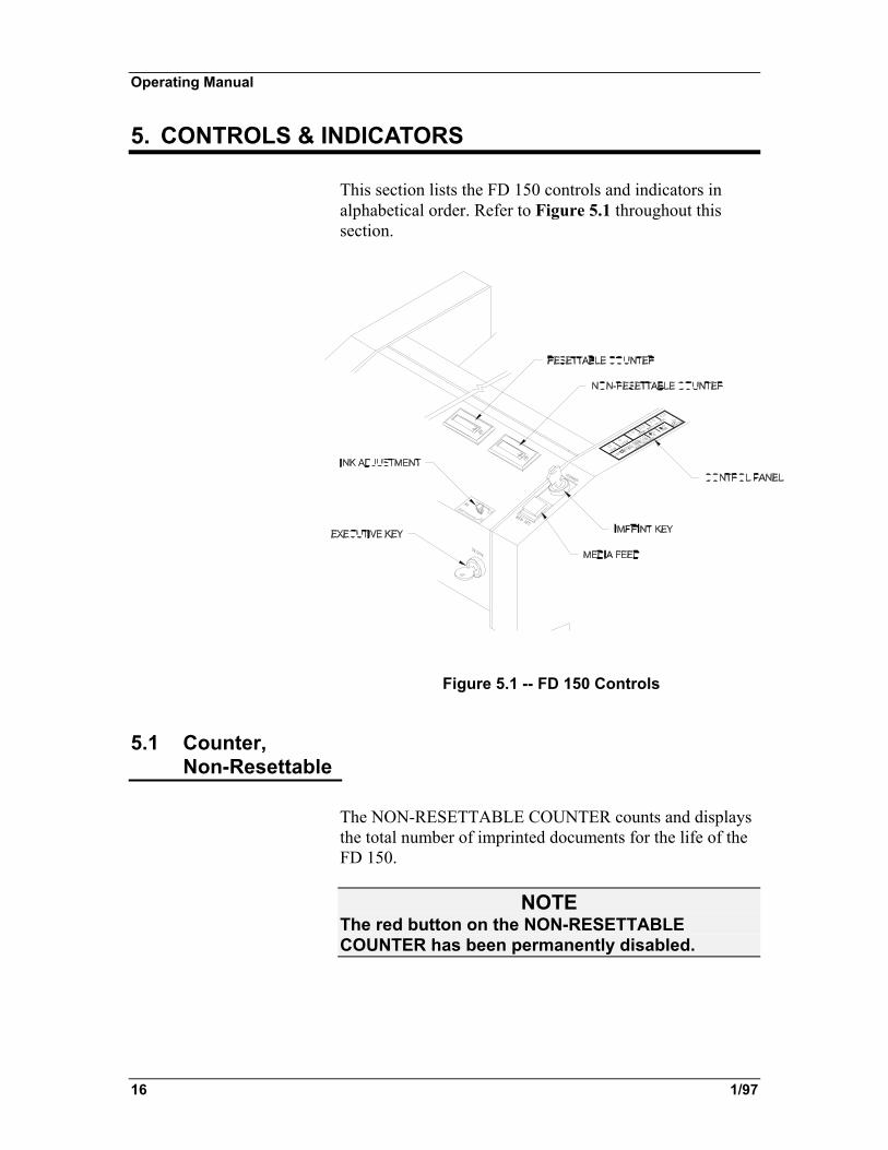
5. CONTROLS & INDICATORS This section lists the FD 150 controls and indicators in alphabetical order. Refer to Figure 5.1 throughout this section.
Figure 5.1 -- FD 150 Controls
5.1 Counter, Non-Resettable
The NON-RESETTABLE COUNTER counts and displays the total number of imprinted documents for the life of the FD 150.
NOTE The red button on the NON-RESETTABLE COUNTER has been permanently disabled.

Operating Manual
1/97 17
5.2 Counter, Resettable
The RESETTABLE COUNTER counts and displays the total number of imprinted documents for each run. Reset this counter at the beginning of each run by pressing the red button.
5.3 Executive Key Two brass EXECUTIVE KEYS come with the FD 150. The EXECUTIVE KEY can be set in two positions: LOCKED and UNLOCKED.
5.3.1 UNLOCKED
Turning the EXECUTIVE KEY to the UNLOCKED position allows you to open the COVER (which disables imprinting) and access the IMPRINT SADDLES.
5.3.2 LOCKED
Turning the EXECUTIVE KEY to the LOCKED position: • locks the COVER which enables imprinting • indexes the SADDLE HOLDER which inks the
IMPRINT SADDLE • allows you to activate the IMPRINT KEY and imprint a
document.
NOTE Turn the EXECUTIVE KEY slowly. If the SADDLE HOLDER does not index, turn the key slower.
5.4 Feed Adjust Knob
The FEED ADJUST KNOB, located behind the PAPER WEIGHT, secures the SEPARATOR. Loosen the FEED ADJUST KNOB to raise or lower the SEPARATOR in order to adjust the size of the gap between the

Operating Manual
18 1/97
SEPARATOR and FEED ROLL. This gap must be adjusted to allow only one document to feed at a time. Once the SEPARATOR is in the correct position, tighten the FEED ADJUST KNOB.
5.5 Imprint Indicator
The IMPRINT INDICATOR is a red light that turns on while a document is being imprinted, then turns off until the next document is imprinted. When the IMPRINT INDICATOR turns ON, the NON-RESETTABLE and RESETTABLE COUNTERS both increment.
5.6 Imprint Key Two silver IMPRINT KEYS are shipped with the FD 150. The IMPRINT KEY has two positions: ON and OFF. (Refer to Figure 5.2.) Turn the IMPRINT KEY to the ON position to start imprinting prior to feeding documents. Turn the IMPRINT KEY to the OFF position to stop imprinting.
5.7 Ink Adjustment Knob
Turn the INK ADJUSTMENT KNOB clockwise to make the imprint darker, counterclockwise to make the imprint lighter.
NOTE If you turn the INK ADJUSTMENT KNOB clockwise as far as it allows and the imprint is still too light or the COVER starts knocking, the INK ROLL must be replaced. For best results, the INK ROLL should just lightly touch the IMPRINT SADDLE. This will also extend the life of the INK ROLL.

Operating Manual
1/97 19
5.8 Imprint Positioning
The IMPRINT POSITIONING controls, located on the CONTROL PANEL include: LIGHT, ↑UP and ↓DOWN. To activate one of these functions, press to the lower left of the LED. Use these controls to set imprint positions. (Refer to Figure 5.2.)
Figure 5.2 -- Control Panel
5.8.1 LIGHT ON / OFF
Toggle the IMPRINT POSITIONING LIGHT ON and
OFF by pressing on the CONTROL PANEL to the lower left of the IMPRINT POSITIONING LED (directly on 1/16"). When the light is ON, the imprint position moves 1" each time ↑UP or ↓DOWN arrow is pressed. When the light is OFF, the imprint position moves 1/16" each time ↑UP or ↓DOWN arrow is pressed.
NOTE
Do not feed documents while adjusting the imprint position.

Operating Manual
20 1/97
5.8.2 ↑UP / ↓DOWN
Press ↑UP to move the imprint position toward the trailing edge of the document. Press ↓DOWN to move the imprint position toward the leading edge of the document. The ↑UP and ↓DOWN lights illuminate with each selection. This means that the imprint position moved the selected amount.
NOTE In order to adjust the imprint position higher or lower, you must use the LIGHT ON / OFF together with the ↑UP / ↓DOWN controls.
5.9 Media Feed To start feeding documents, press the MEDIA FEED button so its light turns ON. This light illuminates while documents are being fed.
NOTE The EXECUTIVE KEY must be in the LOCKED position in order to activate the MEDIA FEED button.

Operating Manual
1/97 21
5.10 Memory Imprint Positions
Set and store up to four imprint positions using the MEMORY IMPRINT POSITIONS controls. (Refer to Figure 5.2.)
5.10.1 POSITIONS 1 - 4
Press the MEMORY IMPRINT POSITIONS 1 - 4 to recall a stored imprint position (which is measured from the leading edge of the document). An imprint position can be set up to 9" (22.86 cm) from the leading edge of the document.
5.10.2 STORE POSITION
Press STORE to save a selected imprint position. Up to four imprint positions can be saved by pressing STORE while at the same time pressing 1 of the 4 MEMORY IMPRINT POSITIONS.
5.11 Paper Weight The PAPER WEIGHT presses down on a stack of loaded documents to aid feeding. If documents don’t require extra weight for proper feeding, the PAPER WEIGHT can be lifted up and locked out of the way.

Operating Manual
22 1/97
5.12 Power Switch The POWER SWITCH is located on the input end next to the POWER ENTRY CASING. Turn the POWER SWITCH ON to supply power to the FD 150.
5.13 Ready Indicator The READY INDICATOR is a red light that turns on when the POWER SWITCH is ON and the EXECUTIVE KEY is in the LOCKED position. It flashes each time the FD 150 detects a document.
5.14 Separators SEPARATORS prevent more than one document from feeding at a time. SEPARATORS can be lifted up and lowered to create the perfect sized gap for documents of different thicknesses.

Operating Manual
1/97 23
6. OPERATION This section shows you how to operate the FD 150. Follow the step-by-step instructions in the order they are presented. Before operating the FD 150, please review Section 4, Power Connection.
WARNING
KEEP LOOSE CLOTHING, TIES, SCARVES, JEWELRY AND HAIR AWAY FROM ALL MOVING PARTS.
WARNING DO NOT PLACE FINGERS BETWEEN OR NEAR MOVING PARTS.
6.1 Loading Saddles
1. Turn the EXECUTIVE KEY to the UNLOCKED
position and open the COVER. 2. Hold down the SADDLE HOLDER LATCH. The short
tip will lift. 3. Place the notch in the IMPRINT SADDLE around the
PIN on the SADDLE HOLDER. (Refer to Figure 6.1.)

Operating Manual
24 1/97
Figure 6.1 -- Loading Imprint Saddles
4. Rest the IMPRINT SADDLE on the SADDLE
HOLDER. 5. Release the SADDLE HOLDER LATCH. It will fit
into the BEVEL in the IMPRINT SADDLE. 6. Close the COVER. Turn the EXECUTIVE KEY slowly
to index the SADDLE HOLDER which inks the IMPRINT SADDLE.
7. To load the second saddle, repeat steps 1-6. To order SADDLES, contact your Formax dealer. Always order SADDLES in pairs.
NOTE Two SADDLES are always necessary for proper imprinting.

Operating Manual
1/97 25
6.2 Loading Documents
Use the following instructions to align and load documents for imprinting. (Refer to Figure 6.2.)
Figure 6.2 -- Paper Path & Marks for Frequently Used Settings
√Tip: Draw marks in-line with the PAPER GUIDES for frequently
used document sizes. 1. Press the MEDIA FEED button so its light turns OFF. 2. Lift up and lock the PAPER WEIGHT. 3. With the FD 150 turned ON, center the document in the
FEED TRAY. 4. Lift up the PAPER GUIDE CAMLOCKS and slide the
PAPER GUIDES to fit the document. The fit should not be binding or sloppy.
5. Push down the PAPER GUIDE CAMLOCKS to lock the PAPER GUIDES in place.

Operating Manual
26 1/97
6. Align the two straight RECEIVING TRAY MAGNETIC DOCUMENT STOPS with the PAPER GUIDES. Center the curved RECEIVING TRAY MAGNETIC DOCUMENT STOP so it stops and stacks the exiting documents.
7. Loosen the FEED ADJUST KNOB and lift up the SEPARATOR.
8. Place one document, face up in the PAPER GUIDES, atop the FEED ROLLS.
Documents LONGER than 9” Use the following instructions to imprint documents longer than approximately 9" (22.86 cm): • If necessary, install the FEED TRAY
EXTENSION by attaching it to the input end of the FD 150 FEED TRAY with the knobs provided.
• Feed the top of the document first. • Install the REVERSE IMPRINT SADDLES.
Refer to Section 6.1 and follow the instructions given for IMPRINT SADDLES. Call your Formax dealer to order these saddles.
9. Lower the SEPARATOR against the document and
tighten the FEED ADJUST KNOB. 10. Now place a stack of documents up to 1½" high, face
up in the PAPER GUIDES. 11. Lower the PAPER WEIGHT to rest on the stack.

Operating Manual
1/97 27
6.3 Feeding Documents
Use the following instructions to feed documents through the FD 150. (Refer to Figure 6.3.)
NOTE Smooth feeding is necessary for accurate imprinting.
Figure 6.3 -- FD 150 Components 1. Turn the POWER SWITCH ON. 2. Turn the IMPRINT KEY OFF. 3. Press the MEDIA FEED button so its light turns ON
and watch that documents feed straight and regularly.

Operating Manual
28 1/97
NOTE
In order to imprint and count properly, documents must feed through the FD 150 accurately. If your FD 150 does not feed documents straight and with a steady rhythm, call your Formax dealer for service. FD 150 feeding components wear with use and need periodic replacement. If multiple documents feed through the FD 150, re-adjust the gap between the SEPARATOR and the FEED ROLL by applying slight downward pressure to the SEPARATOR while tightening the FEED ADJUST KNOB. If the FD 150 feeds with difficulty, re-adjust the gap between the SEPARATOR and the FEED ROLL by tightening the SEPARATOR using the thickness of two documents instead of one. If feeding does not improve, refer back to section 6.2, Loading Documents.
6.4 Setting Imprint Position UP / DOWN
Use the following instructions to change the imprint position toward or away from the leading edge of the document. (Refer to Figure 6.3.)
NOTE Always imprint several void or test documents until the imprint position is exactly where you want it. 1. Turn POWER SWITCH ON. 2. Turn the EXECUTIVE KEY to the LOCKED position
and the IMPRINT KEY ON. (Refer to Figure 6.1.)
NOTE Turn the EXECUTIVE KEY slowly. If the SADDLE HOLDER does not index, turn the key slower.
Operating Manual
1/97 29
3. Press the MEDIA FEED button so its light turns ON. 4. Feed one test document to determine the imprint
position. 5. If the imprint position is not in the desired position,
re-adjust it using the IMPRINT POSITIONING controls.
6. Toggle the IMPRINT POSITIONING LIGHT ON to move the imprint position approximately 1 inch or toggle the IMPRINT POSITIONING LIGHT OFF to move the imprint position approximately 1/16 inch.
7. Press IMPRINT POSITIONING ↑UP to move the imprinting position toward the trailing edge of the document. The amount the imprint position moves is determined by the IMPRINT POSITIONING LIGHT selection.
8. Press ↓DOWN to move the imprinting position toward the leading edge of the document. The amount the imprint position moves is determined by the IMPRINT POSITIONING LIGHT selection.
NOTE Match the IMPRINT POSITION setting to the length of the document. A high setting may position the imprint beyond the trailing edge of a short document. This results in a non-imprinted document. If this occurs, the counter will not count that document.

Operating Manual
30 1/97
6.4.1 Imprint Position Example
Use this example as a guide to understanding the functions of the IMPRINT POSITIONING controls. 1. Feed a test document through the FD 150 to determine
where the current imprint position is. 2. Measure the distance from the current imprint position
to the desired imprint position. Ex. The distance from the current imprint position to the desired imprint position equals 23/16" inches.
3. Toggle the IMPRINT POSITIONING LIGHT ON. 4. Press the ↑UP LED twice to move the imprint
approximately 2 inches from its current position. 5. Toggle the IMPRINT POSITIONING LIGHT OFF. 6. Press the ↑UP LED three times to move the imprint an
additional 3/16 of an inch (i.e., three 1/16" increments). 7. Press the MEDIA FEED button so its light turns on. 8. Feed a test document through the FD 150 to verify and
fine tune the imprint position.

Operating Manual
1/97 31
6.5 Storing An Imprint Position
Use the following procedure to STORE an imprint position. 1. Using the IMPRINT POSITIONING controls, set the
imprint to the desired position. 2. Select a MEMORY IMPRINT POSITION (1-4) in
which to store the current imprint position. 3. Press and hold STORE (LED on) while pressing the
desired MEMORY IMPRINT POSITION (1-4) LED.
NOTE The STORE and MEMORY IMPRINT POSITION LEDs must be illuminated in order for the position to be saved.
6.5.1 Sample Stored Imprint Positions
The MEMORY IMPRINT POSITIONS can be used commonly used jobs. Ex: MEMORY IMPRINT POSITION 1 Payroll MEMORY IMPRINT POSITION 2 Accounts Payable MEMORY IMPRINT POSITION 3 Endorsing MEMORY IMPRINT POSITION 4 Form Letter

Operating Manual
32 1/97
6.6 Setting Imprint Position LEFT / RIGHT
Use the following instructions to move the imprint position left and right on the document. (Refer to Figure 6.4.)
Figure 6.4 -- Setting Imprint Position Left / Right
1. Turn the POWER SWITCH OFF. 2. Turn the EXECUTIVE KEY to the UNLOCKED
position and open the COVER. 3. Locate the SADDLE HOLDER SCREW midway
between the two IMPRINT SADDLES. (Refer to Figure 6.4.)
4. If you cannot see the SADDLE HOLDER, turn the POWER SWITCH ON. Close the COVER and slowly turn the EXECUTIVE KEY to the LOCKED position indexing the SADDLE HOLDER.
5. Open the COVER.

Operating Manual
1/97 33
NOTE When using ENDORSING SADDLES, remove the saddle to find the SADDLE HOLDER SCREW. 6. Using the supplied allen wrench, loosen the SADDLE
HOLDER SCREW.
NOTE Only loosen this screw 1-2 turns, or until the SADDLE HOLDER will slide. The SADDLE HOLDER SCREW must stay in the IMPRINT SHAFT GROOVE. 7. Slide the SADDLE HOLDER to the desired position. 8. Tighten the SADDLE HOLDER SCREW. 9. Slide the INK ROLL CARRIAGE to align it with the
SADDLE HOLDER.
NOTE Use care when handling the INK ROLL. The ink is indelible and will not wash out of clothing. 10. Close the COVER.

Operating Manual
34 1/97
6.7 Imprinting Documents
Use the following instructions to imprint documents. 1. Turn POWER SWITCH ON. 2. Turn the EXECUTIVE KEY slowly to the LOCKED
position. (Refer to Figure 6.1.)
NOTE If the SADDLE HOLDER does not index, turn the key slower. 3. Check the FEED TRAY to be sure that documents are
loaded properly. Refer to Section 6.2. 4. Check the RECEIVING TRAY to be sure that
MAGNETIC PAPER GUIDES are set properly. Refer to Section 6.2
5. Press the MEDIA FEED button so its light turns ON. 6. If documents feed straight and regularly, press the
MEDIA FEED button OFF and turn the IMPRINT KEY to ON.
7. Press the MEDIA FEED button quickly ON and OFF to feed a single test document.
8. Adjust the imprint position if necessary. Refer to Sections 6.4 and 6.6.
9. Make Log Book entries and re-set counter. 10. Press the MEDIA FEED button and imprint the rest of
the documents.
NOTE If you encounter a problem, (i.e. - jammed documents, wrong imprint position, erratic feeding, etc.) STOP feeding immediately by pressing the MEDIA FEED button so its light turns OFF.

Operating Manual
1/97 35
6.8 Feeding Various Sized Documents
Use the following procedures to imprint various sized documents at one time. 1. Place the documents between the PAPER GUIDES.
Justify the documents to the right with the leading edge as shown in Figure 6.5.
Figure 6.5 -- Right Justified Documents

Operating Manual
36 1/97
7. MAINTENANCE Clean and inspect your FD 150 regularly.
WARNING ALWAYS UNPLUG THE POWER CORD BEFORE CLEANING OR SERVICING THE FD 150.
7.1 Pressure Tire Shaft Removal & Installation
In case of jams or when cleaning, you’ll need the following instructions to remove and install the PRESSURE TIRE SHAFT. (Refer to Figure 7.1.)
Figure 7.1 -- Pressure Tire Shaft Assembly

Operating Manual
1/97 37
1. Turn the EXECUTIVE KEY to the UNLOCKED position and open the COVER.
2. Grasp the pressure tires and push the spring-loaded end of the PRESSURE TIRE SHAFT into the hole opposite the operator’s side.
3. Pull the d-hole end of the shaft up and out of the FD 150, removing the shaft.
4. To install, push the spring-loaded end of the PRESSURE TIRE SHAFT into its hole.
5. Mate the other end of the PRESSURE TIRE SHAFT into the d-hole on the operator’s side and release.
6. Close the COVER.
7.2 Cleaning Use the following instructions to clean the exterior and paper path of the FD 150. Refer to Figure 7.2 throughout this procedure.
Figure 7.2 -- Under Cover View of the FD 150 with the Tire Pressure Shaft Removed

Operating Manual
38 1/97
1. Clean the FD 150 exterior surfaces periodically with a mild soap cleaner and a cloth. This will help maintain the appearance and operation of the machine.
NOTE
If you cannot remove ink from the FD 150 with a mild soap cleaner, use lemon extract.
√Tip: Clean ink off your hands with rubbing alcohol or pumice soap. 2. Using compressed air, blow away any dust or debris
from the outside of the FD 150. 3. Open the COVER. 4. Using compressed air, blow away any dust or debris
from the inside of the FD 150. Aim at the photosensors.
NOTE Do not hold the compressed air can close enough to the PHOTOSENSORS to freeze them. 5. Clean the FEED ROLL, TRANSPORT ROLLS,
BUMPER WHEEL (which is on the FEED TRAY), SADDLE HOLDER, IMPRINT SADDLES and the BACKUP PLATEN with isopropyl alcohol and a cloth.
NOTE
Clean the PRESSURE TIRES with a dry cloth or dry coarse brush ONLY. Do not clean these rolls with alcohol or any other liquid cleaner. 6. Close the COVER.
7.3 Replacing A Fuse
When one or both FUSES are blown, the FD 150 will appear to have no power. If the FD 150 has blown a FUSE, replace the fuse. The FUSE DRAWER is located on the input end of the machine. Use the following instructions to replace one or both FUSES. (Refer to Figure 7.3.)

Operating Manual
1/97 39
WARNING
A BLOWN FUSE IN THE NEUTRAL LEG COULD MEAN THAT INTERIOR PARTS OF THE FD 150 REMAIN AT A HAZARDOUS VOLTAGE. ALWAYS UNPLUG THE POWER CORD BEFORE SERVICING THE FD 150.
Figure 7.3 -- Replacing A Fuse 1. Unplug the POWER CORD. 2. Use a small screwdriver or similar tool to push up on
and release the FUSE DRAWER LOCKING TAB. 3. Pull the FUSE DRAWER out of the POWER ENTRY
CASING. 4. Inspect the FUSES; look for blackened glass, melted
wire or a disconnected wire between the ends of the tube. If you find any of these problems in either FUSE, that FUSE is blown and needs to be replaced.
5. Pull the blown FUSE from its slot. 6. Place a new FUSE into the same slot. Both fuses must
be in place for the FD 150 to operate properly. 7. Install the FUSE DRAWER in the POWER ENTRY
CASING.

Operating Manual
40 1/97
8. TROUBLESHOOTING This section helps you identify and correct machine and operator errors.
8.1 Improper Imprinting
This section lists the different circumstances that prevent or interrupt proper imprinting and explains the solution to each problem. Each circumstance is on the far left with an explanation on the right.
8.1.1 Double Feeding
If the gap between the SEPARATOR and the FEED ROLL is too large, more than one document may be fed at a time. If there is no separation between documents, the leading document will be imprinted but the overlapping document will not. Re-adjust the FEED ADJUST KNOB. Refer to Section 6.3.
8.1.2 Executive Key Turned Too Quickly
If the SADDLE HOLDER does not index when you turn the EXECUTIVE KEY to the LOCKED position, you have turned the EXECUTIVE KEY too quickly. The first few imprints may not appear in the desired position. To index the SADDLE HOLDER, turn the EXECUTIVE KEY to the UNLOCKED position, then slowly turn it back to the LOCKED position.

Operating Manual
1/97 41
8.1.3 Imprint Is Too Light
Replace the INK ROLL if the imprint does not improve after turning the INK ADJUSTMENT KNOB. The INK ROLL also needs to be replaced if you hear the COVER knocking. Refer to Figure 8.1 throughout this procedure.
Figure 8.1 -- Ink Roll Installation
NOTE
Before replacing the used INK ROLL, put on the gloves provided with the new INK ROLL. 1. Open the COVER. 2. Pull out the COTTER PIN. 3. Hold the INK ROLL currently installed in the FD 150. 4. Pull out the AXLE. 5. Discard the used INK ROLL. 6. Hold the new INK ROLL between the sides of the INK
ROLL CARRIAGE. 7. Insert the AXLE, pointed end first, through the holes in
the INK ROLL CARRIAGE. 8. Insert the straight side of the COTTER PIN into the
hole in the pointed end of the AXLE.

Operating Manual
42 1/97
9. Push the COTTER PIN until the AXLE is secured between the two CLIPS on the COTTER PIN.
8.1.4 Document Jam
If the FD 150 stops feeding, there may be one or more documents jammed inside the machine. To clear a jam, follow this procedure: 1. Unplug the POWER CORD. 2. Turn the EXECUTIVE KEY to the UNLOCKED
position. 3. Open the COVER. 4. Remove the PRESSURE TIRE SHAFT by pushing the
spring-loaded end of the PRESSURE TIRE SHAFT toward the hole opposite the operator’s side. Pull the other end toward you and out of the machine.
5. Pull any jammed documents out of the FD 150. 6. Push the spring loaded end of the PRESSURE TIRE
SHAFT into hole opposite the operator side. 7. Mate the other end of the PRESSURE TIRE SHAFT
into the d-hole on the operator’s side and release.
8.2 Troubleshooting Chart
The following Troubleshooting Chart helps you identify and correct malfunctions. To use the Troubleshooting Chart: 1. Locate the malfunctions in the trouble column. 2. Read across to the cause column. 3. Follow the instructions given in the remedy column.

Operating Manual
1/97 43
WARNING
DISCONNECT THE POWER CORD BEFORE CLEANING, CLEARING OR REPAIRING THE FD 150. Troubleshooting Chart
trouble cause remedy
1. Nothing works.
POWER SWITCH is turned OFF.
Turn POWER SWITCH ON.
POWER CORD is damaged or not plugged into proper voltage receptacle.
Inspect the POWER CORD and plug into the proper receptacle, or replace the POWER CORD if necessary.
Receptacle does not have power present.
Check the circuit source for a blown FUSE or circuit breaker, or other problems.
Power entry FUSE is blown.
Follow the procedure for replacing a FUSE. Refer to Section 7.2.
4330S keeps blowing FUSES.
Contact your Formax Dealer.
2. Does not feed. MEDIA FEED button is turned OFF.
Press the MEDIA FEED button so its light turns ON.
Gap between the SEPARATOR and FEED ROLL is too small to feed documents.
Turn the FEED ADJUST KNOB to enlarge the gap.
3. Feeds but does not imprint.
IMPRINT KEY is not in the ON position.
Turn the IMPRINT KEY to the ON position.
Imprint position is set beyond trailing edge of document.
Select a different MEMORY IMPRINT POSITION or re-adjust the imprint position. Refer to Sections 6.4 & 6.6.

Operating Manual
44 1/97
trouble cause remedy
4. Misplaced imprint.
Imprint position is not set correctly.
Select a different MEMORY IMPRINT POSITION or re-adjust the imprint position. Refer to Sections 6.4 & 6.6.
SADDLE HOLDER and INK ROLL CARRIAGE are not located correctly.
Re-adjust imprint position. Refer to Section 6.6.
EXECUTIVE KEY was turned too quickly to index SADDLE HOLDER.
Turn the EXECUTIVE KEY to the UNLOCKED position, then slowly turn it to the LOCKED position.
5. Partial ink on document.
INK ROLL is not positioned over the IMPRINT SADDLE correctly.
Open the COVER and align the INK ROLL CARRIAGE directly above the SADDLE HOLDER.
6. Light imprint. IMPRINT SADDLES are not being inked.
Turn the INK ADJUSTMENT KNOB clockwise to darken imprint.
INK ROLL is out of ink. Install a new INK ROLL. To order a new INK ROLL, call your Formax Dealer.
IMPRINT SADDLES are worn.
Install new IMPRINT SADDLES. To order a new pair, call your Formax Dealer.