fcu 1000 series fluidcontrol unit - hydacfluidcontrol unit - fcu 1000 series hydac filtertechnik...
TRANSCRIPT
FCU 1000 Series FluidControl Unit
Operating and Maintenance Instructions English (Translation of original)
Valid from firmware versions V 1.10 up
Doc.: 3371346a / 2007-12-03
FluidControl Unit - FCU 1000 Series
HYDAC Filtertechnik GmbH en Page 2BeWa_FCU1000_3371346a_en.doc 2007-12-04
Trademarks The trademarks of other companies are exclusively used for the products of those companies.
Copyright © 2007 by HYDAC Filtertechnik GmbH all rights reserved All rights reserved. This manual may not be reproduced in part or whole without the explicit written agreement from HYDAC Filtertechnik. Contraventions are liable to compensation.
Exclusion of liability We made every endeavor to ensure the accuracy of the contents of this document. However, errors cannot be ruled out. Consequently, we accept no liability for such errors as may exist nor for any damage or loss whatsoever which may arise as a result of such errors. We welcome any suggestions for improvements.
All details are subject to technical modifications.
Technical specifications are subject to change without notice.
HYDAC Filtertechnik GmbH
Hydac Service Technology Division / Filter Systems
P.O. Box 12 51
66273 Sulzbach / Saar - Deutschland
Tel.: ++49 (0) 6897 / 509 - 01
Fax: ++49 (0) 6897 / 509 - 846
FluidControl Unit - FCU 1000 Series
HYDAC Filtertechnik GmbH en Page 3BeWa_FCU1000_3371346a_en.doc 2007-12-04
Contents Contents..................................................................................................................................3 What's New — Document History.........................................................................................5 Preface ....................................................................................................................................6
Customer Service .................................................................................................................7 Modifications to the Product .................................................................................................7 Warranty ...............................................................................................................................7 Using the documentation ......................................................................................................8
1 General Safety Precautions ...........................................................................................9 1.1 Obligations and Liability .............................................................................................9 1.2 Explanation of Symbols and Warnings, etc. .............................................................10
1.2.1 Basic Symbols...............................................................................................10 1.3 Proper/Designated Use ............................................................................................10 1.4 Improper Use............................................................................................................11 1.5 Informal Safety Precautions .....................................................................................11 1.6 How to behave in case of emergency ......................................................................11 1.7 Safety measures to be followed in normal operation................................................11 1.8 Electrical Hazards ....................................................................................................12 1.9 Maintenance, Servicing and Troubleshooting ..........................................................12 1.10 Modifications to the FCU ..........................................................................................12 1.11 Cleaning the FCU and disposal of the media and agents used ...............................12
2 Transportation/Package/Storage.................................................................................13 2.1 Packing / transportation............................................................................................13 2.2 Storage.....................................................................................................................13
2.2.1 Storage conditions ........................................................................................13 3 Decoding the model code label ...................................................................................13 4 Checking the scope of delivery ...................................................................................14 5 Using the FCU ...............................................................................................................15
5.1 Mode of Function......................................................................................................16 5.2 Operation panel........................................................................................................18 5.3 Dimensions...............................................................................................................19 5.4 Hydraulic schematic .................................................................................................19
6 Preparing the FCU.........................................................................................................20 6.1 Attaching OUTLET quick-action coupling.................................................................20 6.2 Hydraulic connection of the FCU..............................................................................20
6.2.1 Connection at the measurement point up to max. 45 bar .............................21 6.2.2 Connection at the measurement point with 45 ... 345 bar.............................23 6.2.3 Selecting the measurement point..................................................................25 6.2.4 Connection at the measurement point - non-pressurized tank .....................26
6.3 Electrical connection of the FCU ..............................................................................27 7 Operating the FCU ........................................................................................................28
FluidControl Unit - FCU 1000 Series
HYDAC Filtertechnik GmbH en Page 4BeWa_FCU1000_3371346a_en.doc 2007-12-04
7.1 Display and keypad elements ..................................................................................28 7.1.1 Measured variables.......................................................................................29
7.1.1.1 Measured variable "ISO"...............................................................................29 7.1.1.2 Measured variable "SAE"..............................................................................29 7.1.1.3 Measured variable "NAS"..............................................................................29 7.1.1.4 Measured variable "Water saturation"...........................................................29 7.1.1.5 Measured variable "Temperature" ................................................................30
7.1.2 Service variables...........................................................................................30 7.1.2.1 Service variables "Flow"................................................................................30 7.1.2.2 Service variables "Drive"...............................................................................30
7.1.3 Switching the display.....................................................................................31 7.1.4 Activate / deactivate keypad lock. .................................................................31
7.2 Modes and menus....................................................................................................32 7.2.1 Power Up Menu ............................................................................................32 7.2.2 Measuring Menu ISO / SAE ..........................................................................33 7.2.3 Menu structure ISO / SAE.............................................................................34 7.2.4 Measuring Menu ISO / NAS..........................................................................34 7.2.5 Menu structure ISO / NAS.............................................................................35
8 Performing a measurement..........................................................................................35 8.1 Restrictions pertaining to use ...................................................................................35
9 Dismantling the FCU.....................................................................................................36 10 FCU interfaces...............................................................................................................37
10.1 DATA (HYDAC Sensor Interface - HSI) ...................................................................37 10.1.1 Connecting the FCU with HMG 510 / HMG 3000 .........................................38 10.1.2 Connecting the FCU with CSI-B-2 ................................................................39
10.2 Bluetooth interface ...................................................................................................40 10.2.1 Installing the Bluetooth USB adaptor ............................................................41 10.2.2 Connecting the FCU via Bluetooth................................................................41
10.3 Measurement value readouts with FluMoS ..............................................................41 11 Conducing maintenance ..............................................................................................42
11.1 Cleaning the FCU.....................................................................................................42 11.2 Rinsing the FCU .......................................................................................................42
11.2.1 Performing a rinsing ......................................................................................42 11.3 Cleaning the suction strainer....................................................................................43 11.4 Checking the high pressure adaptor ........................................................................47
11.4.1 Cleaning / changing the strainer in the high pressure adaptor......................47 11.4.2 Cleaning / changing the strainer in the high pressure adaptor......................48
11.5 Disposing of the FCU ...............................................................................................48 12 FCU status messages...................................................................................................49
12.1 Status LED / Display ................................................................................................49 12.2 Error Message..........................................................................................................49 12.3 Exceptions Errors .....................................................................................................50
13 Spare Parts ....................................................................................................................51
FluidControl Unit - FCU 1000 Series
HYDAC Filtertechnik GmbH en Page 5BeWa_FCU1000_3371346a_en.doc 2007-12-04
13.1 Accessories ..............................................................................................................53 14 Technical Data...............................................................................................................54 15 ISO 4406 / SAE AS 4059 and NAS 1638 Classes ........................................................56
15.1 ISO 4406:1999 .........................................................................................................56 15.1.1 ISO 4406 table ..............................................................................................56 15.1.2 Overview of the differences between ISO 4406:1987 and ISO 4406:1999...57
15.2 SAE AS 4059 ...........................................................................................................58 15.2.1 SAE AS 4059 table .......................................................................................58 15.2.2 Cleanliness classes according to SAE..........................................................58
15.2.2.1 Absolute particle count larger than a defined particle size............................58 15.2.2.2 Specifying a cleanliness class for each particle size.....................................59 15.2.2.3 Specifying the highest cleanliness class measured ......................................59
15.3 NAS 1638 .................................................................................................................59 16 Service ...........................................................................................................................60
16.1 Shipping Address for Recalibration and Repair Work ..............................................60 16.2 Calibrating the FCU..................................................................................................60
17 EC declaration of conformity .......................................................................................61
What's New — Document History The index is featured on the cover sheet of the operating and maintenance manual and in the lower left corner of each page after the part number.
Index "a" - from firmware version V 1.10 - Change in scope of delivery - Change in Bluetooth device name in "FCU1310"
FluidControl Unit - FCU 1000 Series
HYDAC Filtertechnik GmbH en Page 6BeWa_FCU1000_3371346a_en.doc 2007-12-04
Preface
For you, as the owner of a product manufactured by us, we have produced this manual, comprising the most important instructions for its operation and maintenance.
It is intended to help you become acquainted with the ins and outs of the product and use it properly.
You should keep it in the vicinity of the product so it is always at your fingertips.
Sometimes the information contained in the documentation cannot always keep up with changes made to the product as we attach considerable importance to keeping our products cutting-edge. Consequently, there might be deviations in technical details, illustrations and dimensions.
If you discover errors while reading the documentation or have suggestions or other useful information, please don’t hesitate to contact us:
HYDAC Filtertechnik GmbH SVFI, Technical Documentation Department Postfach 12 51 66273 Sulzbach / Saar, Germany
Fax: ++49 (0) 6897 509 846 E-mail: [email protected]
We look forward to receiving your input.
Our motto: “Putting experience into practice”
FluidControl Unit - FCU 1000 Series
HYDAC Filtertechnik GmbH en Page 7BeWa_FCU1000_3371346a_en.doc 2007-12-04
Customer Service If you have any questions, suggestions, or encounter any problems of a technical nature, please don't hesitate to contact us. When contacting us, please always include the model/type designation and article no. of the product:
Fax: ++49 (0) 6897 509 846 Email: [email protected]
Modifications to the Product We would like to point out that changes to the product (e.g. purchasing options, etc.) may result in the information in the operating instructions no longer being completely accurate or sufficient.
When making modifications or performing repair work to components affecting the safety of the product, the product may not be put back into operation until it has been examined and released by a HYDAC representative.
Please notify us immediately of any modifications made to the product whether by you or a third party.
Warranty For the warranty provided by us, please refer to the General Terms of Sale and Delivery of HYDAC Filtertechnik GmbH.
They are available at: www.hydac.com Legal information.
FluidControl Unit - FCU 1000 Series
HYDAC Filtertechnik GmbH en Page 8BeWa_FCU1000_3371346a_en.doc 2007-12-04
Using the documentation
Please note that the method described above of locating specific information does not release you from your responsibility for carefully reading the entire manual prior to starting the unit up for the first time and carefully rereading the manual at regular intervals later on.
WHAT do I want to know? I determine which topic I am looking for.
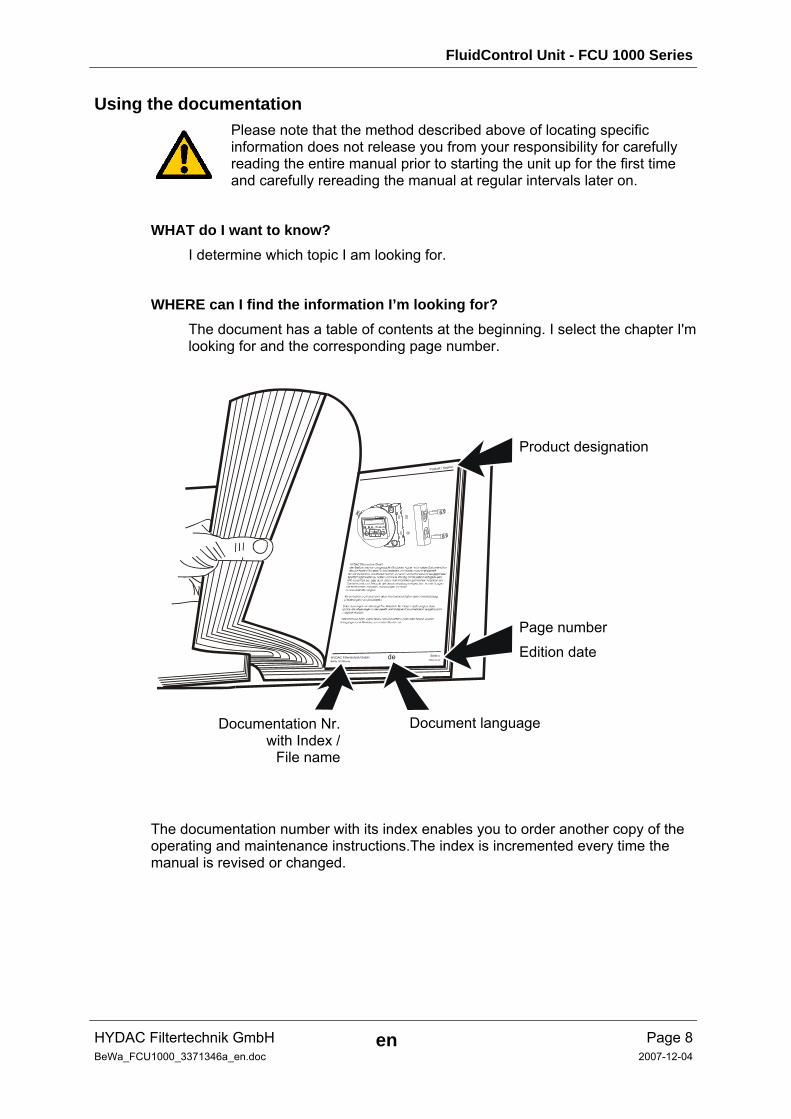
WHERE can I find the information I’m looking for? The document has a table of contents at the beginning. I select the chapter I'm looking for and the corresponding page number.
deHYDAC Filtertechnik GmbHBeWa 123456a de
Seite x
Produkt / Kapitel
200x-xx-xx
The documentation number with its index enables you to order another copy of the operating and maintenance instructions.The index is incremented every time the manual is revised or changed.
Product designation
Page number
Edition date
Document language Documentation Nr.with Index /
File name
FluidControl Unit - FCU 1000 Series
HYDAC Filtertechnik GmbH en Page 9BeWa_FCU1000_3371346a_en.doc 2007-12-04
1 General Safety Precautions These operating instructions contain the key instructions for properly and safely operating the FCU.
1.1 Obligations and Liability • The basic prerequisite for the safe and proper handling and operation of the FCU is
knowledge of the safety instructions and warnings.
• These operating instructions in general, and the safety precautions in particular, are to be adhered by all those who work with the FCU.
• Adherence is to be maintained to pertinent accident prevention regulations applicable at the site where the product is used.
• The safety precautions listed herein are limited solely to using the FCU.
The FCU has been designed and constructed in accordance with the current state of the art and recognized safety regulations. Nevertheless, hazards may be posed to the life and limb of the individual using the product or to third parties. Risk of damage may be posed to the product or other equipment and property. The FCU is only to be used as follows:
• solely for its designated use
• only when in a safe, perfect condition
• any faults or malfunctions which might impair safety are to be properly repaired or remedied immediately.
Our General Terms and Conditions apply. They are made available to the owner upon concluding purchase of the unit at the latest. Any and all warranty and liability claims for personal injuries and damage to property shall be excluded in the event they are attributable to one or more of the following causes:
• improper use of the FCU or use deviating from its designated use
• improper assembly, installation, commissioning, operation and maintenance of the FCU
• operating the FCU when the system equipment or systems are defective
• modifications to the product made by the user or purchaser
• improper monitoring of product components subject to wear and tear
• improperly performed repair work
FluidControl Unit - FCU 1000 Series
HYDAC Filtertechnik GmbH en Page 10BeWa_FCU1000_3371346a_en.doc 2007-12-04
1.2 Explanation of Symbols and Warnings, etc. The following designations and symbols are used in this manual to designate hazards, etc.:
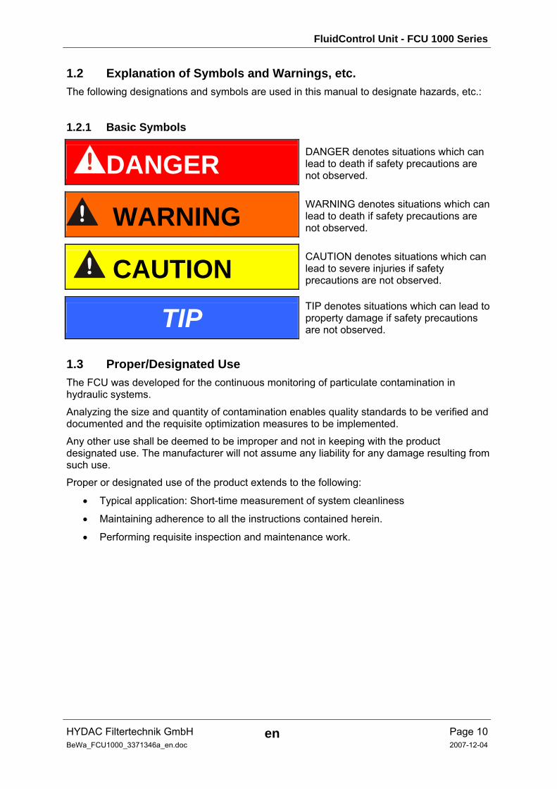
1.2.1 Basic Symbols
DANGER DANGER denotes situations which can lead to death if safety precautions are not observed.
WARNING WARNING denotes situations which can lead to death if safety precautions are not observed.
CAUTION CAUTION denotes situations which can lead to severe injuries if safety precautions are not observed.
TIP TIP denotes situations which can lead to property damage if safety precautions are not observed.
1.3 Proper/Designated Use The FCU was developed for the continuous monitoring of particulate contamination in hydraulic systems.
Analyzing the size and quantity of contamination enables quality standards to be verified and documented and the requisite optimization measures to be implemented.
Any other use shall be deemed to be improper and not in keeping with the product designated use. The manufacturer will not assume any liability for any damage resulting from such use.
Proper or designated use of the product extends to the following:
• Typical application: Short-time measurement of system cleanliness
• Maintaining adherence to all the instructions contained herein.
• Performing requisite inspection and maintenance work.
FluidControl Unit - FCU 1000 Series
HYDAC Filtertechnik GmbH en Page 11BeWa_FCU1000_3371346a_en.doc 2007-12-04
1.4 Improper Use Improper use may result in hazard to life and limb. Examples of improper use:
• Long-term measurement of system cleanliness
• improper connection of the FluidControl Unit pressure and return flow hoses.
1.5 Informal Safety Precautions Make sure to always keep the operating instructions in the vicinity of the product.
In addition to the manual, the general and local regulations concerning accident prevention and protection of the environment should be available and observed.
Make sure to keep the safety and hazard symbols and warnings on the product in a legible condition.
Before opening any components of the FCU, all electric plugs/cords and hydraulic lines are to be removed. Tests conducted with the housing open may only be performed by properly trained, certified electricians. This also applies to all repair work or to any modifications to electrical / hydraulic components approved by us.
The hoses and connection fittings are to be checked daily for leakage (visual check). The electrical components of the product are to also be regularly checked (visual check once a month). Any loose connections or damaged cables or hoses are to be replaced immediately with original spare parts.
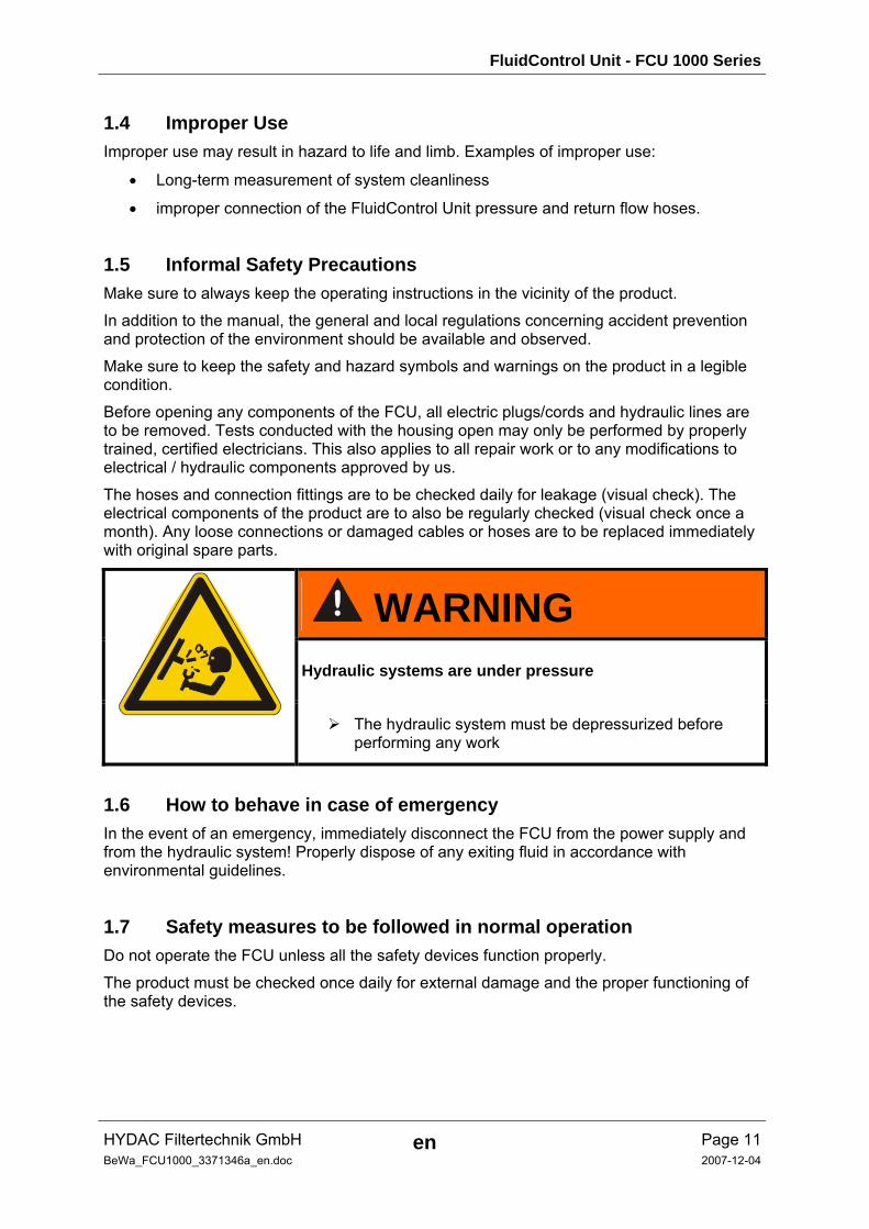
WARNING Hydraulic systems are under pressure
The hydraulic system must be depressurized before
performing any work
1.6 How to behave in case of emergency In the event of an emergency, immediately disconnect the FCU from the power supply and from the hydraulic system! Properly dispose of any exiting fluid in accordance with environmental guidelines.
1.7 Safety measures to be followed in normal operation Do not operate the FCU unless all the safety devices function properly.
The product must be checked once daily for external damage and the proper functioning of the safety devices.
FluidControl Unit - FCU 1000 Series
HYDAC Filtertechnik GmbH en Page 12BeWa_FCU1000_3371346a_en.doc 2007-12-04
1.8 Electrical Hazards
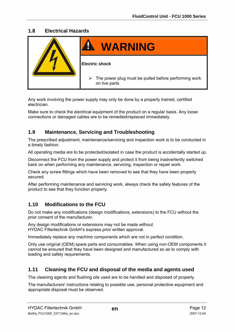
WARNING Electric shock
The power plug must be pulled before performing work
on live parts
Any work involving the power supply may only be done by a properly trained, certified electrician.
Make sure to check the electrical equipment of the product on a regular basis. Any loose connections or damaged cables are to be remedied/replaced immediately.
1.9 Maintenance, Servicing and Troubleshooting The prescribed adjustment, maintenance/servicing and inspection work is to be conducted in a timely fashion.
All operating media are to be protected/isolated in case the product is accidentally started up.
Disconnect the FCU from the power supply and protect it from being inadvertently switched back on when performing any maintenance, servicing, inspection or repair work.
Check any screw fittings which have been removed to see that they have been properly secured.
After performing maintenance and servicing work, always check the safety features of the product to see that they function properly.
1.10 Modifications to the FCU Do not make any modifications (design modifications, extensions) to the FCU without the prior consent of the manufacturer.
Any design modifications or extensions may not be made without HYDAC Filtertechnik GmbH’s express prior written approval.
Immediately replace any machine components which are not in perfect condition.
Only use original (OEM) spare parts and consumables. When using non-OEM components it cannot be ensured that they have been designed and manufactured so as to comply with loading and safety requirements.
1.11 Cleaning the FCU and disposal of the media and agents used The cleaning agents and flushing oils used are to be handled and disposed of properly.
The manufacturers' instructions relating to possible use, personal protective equipment and appropriate disposal must be observed.
FluidControl Unit - FCU 1000 Series
HYDAC Filtertechnik GmbH en Page 13BeWa_FCU1000_3371346a_en.doc 2007-12-04
2 Transportation/Package/Storage
2.1 Packing / transportation Unpack the unit and check it for damage in transit. Report any damage to the forwarding agent immediately
2.2 Storage Make sure to store the FCU in a clean, dry place.
If the FCU is to be put into storage for an extended period of time, it should be completely drained and flushed to prevent it from gumming up.
The cleaning agents and flushing oils used are to be handled and disposed of properly.
2.2.1 Storage conditions Storage temperature: -40°C - +80°C / -40°F - + 176°F
Relative humidity max. 90% non-condensing
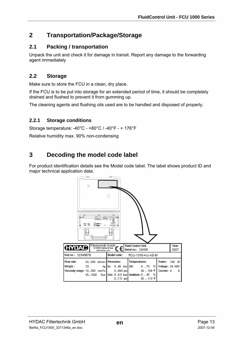
3 Decoding the model code label For product identification details see the Model code label. The label shows product ID and major technical application data.
FluidControl Unit - FCU 1000 Series
HYDAC Filtertechnik GmbH en Page 14BeWa_FCU1000_3371346a_en.doc 2007-12-04
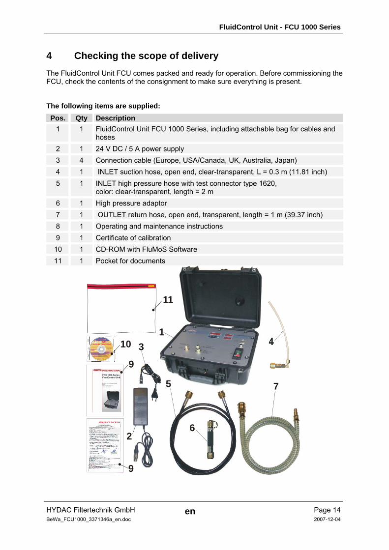
4 Checking the scope of delivery The FluidControl Unit FCU comes packed and ready for operation. Before commissioning the FCU, check the contents of the consignment to make sure everything is present.
The following items are supplied: Pos. Qty Description
1 1 FluidControl Unit FCU 1000 Series, including attachable bag for cables and hoses
2 1 24 V DC / 5 A power supply 3 4 Connection cable (Europe, USA/Canada, UK, Australia, Japan) 4 1 INLET suction hose, open end, clear-transparent, L = 0.3 m (11.81 inch) 5 1 INLET high pressure hose with test connector type 1620,
color: clear-transparent, length = 2 m 6 1 High pressure adaptor 7 1 OUTLET return hose, open end, transparent, length = 1 m (39.37 inch) 8 1 Operating and maintenance instructions 9 1 Certificate of calibration
10 1 CD-ROM with FluMoS Software 11 1 Pocket for documents
3
9
9
10
11
1
2
7
4
5
6
FluidControl Unit - FCU 1000 Series
HYDAC Filtertechnik GmbH en Page 15BeWa_FCU1000_3371346a_en.doc 2007-12-04
5 Using the FCU The FCU 1000 is a portable service unit for the temporary measurement of particulate contamination in hydraulic systems. With the integrated AquaSensor AS 1000, the measurements can be expanded to include the saturation level of water in hydraulic media in % and temperature.
The installed pump and hoses included in delivery can be applied to:
• Control circuits
• Pressure circuits
• non-pressurized tanks
Performance Features:
• Particulate contamination detection by use of an optical measurement cell
• Applicable for hydraulic fluids 10 … 350 mm²/s / 16 … 1622 Sus (ISO VG 68)
• Integrated AquaSensor AS 1000 for the measurement of humidity and temperature
• Automatic measurement and display of cleanliness ratings as
ISO 4406:1987; NAS 1638
ISO 4406:1999; SAE AS 4059 (D)
• Measurement Accuracy +/- ½ ISO code
• Supply voltage 24 V DC / 4 A
• Operating pressure max. 45 bar / max. 650 psi, operating pressure with pressure adaptor max. 345 bar / max. 5000 psi
• Integrated pump for the automatic control of oil flow
FluidControl Unit - FCU 1000 Series
HYDAC Filtertechnik GmbH en Page 16BeWa_FCU1000_3371346a_en.doc 2007-12-04
5.1 Mode of Function
INLET
ContaminationSensor
12
2
31617
14
10
1
413
OUTLET
Display
Keypad
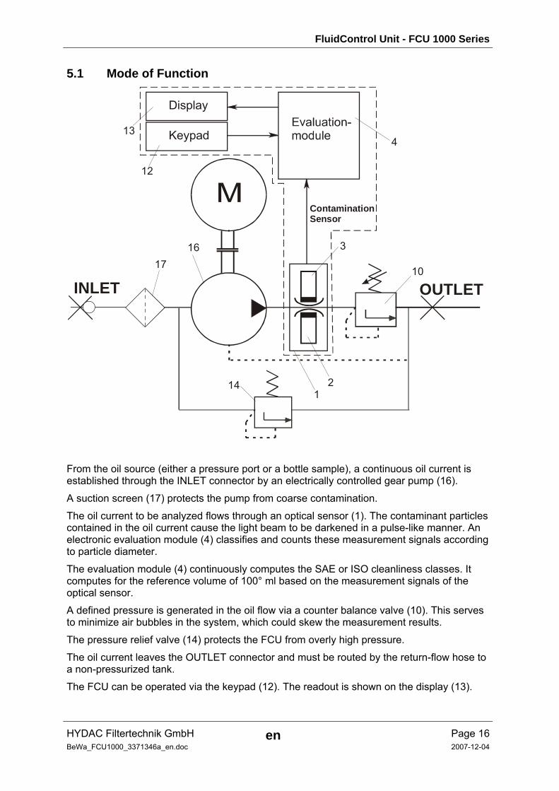
From the oil source (either a pressure port or a bottle sample), a continuous oil current is established through the INLET connector by an electrically controlled gear pump (16).
A suction screen (17) protects the pump from coarse contamination.
The oil current to be analyzed flows through an optical sensor (1). The contaminant particles contained in the oil current cause the light beam to be darkened in a pulse-like manner. An electronic evaluation module (4) classifies and counts these measurement signals according to particle diameter.
The evaluation module (4) continuously computes the SAE or ISO cleanliness classes. It computes for the reference volume of 100° ml based on the measurement signals of the optical sensor.
A defined pressure is generated in the oil flow via a counter balance valve (10). This serves to minimize air bubbles in the system, which could skew the measurement results.
The pressure relief valve (14) protects the FCU from overly high pressure.
The oil current leaves the OUTLET connector and must be routed by the return-flow hose to a non-pressurized tank.
The FCU can be operated via the keypad (12). The readout is shown on the display (13).

FluidControl Unit - FCU 1000 Series
HYDAC Filtertechnik GmbH en Page 17BeWa_FCU1000_3371346a_en.doc 2007-12-04
The electronic evaluation module provides for the continuous monitoring of the following:
• the particle sensor function
• the oil flow
• the power supply voltage
When a malfunction occurs, an error message automatically appears in the display and interrupts the measurement. The evaluation module will recognize when the cause of error has been corrected, and the unit will reset automatically and resume the measurement operation.
FluidControl Unit - FCU 1000 Series
HYDAC Filtertechnik GmbH en Page 18BeWa_FCU1000_3371346a_en.doc 2007-12-04
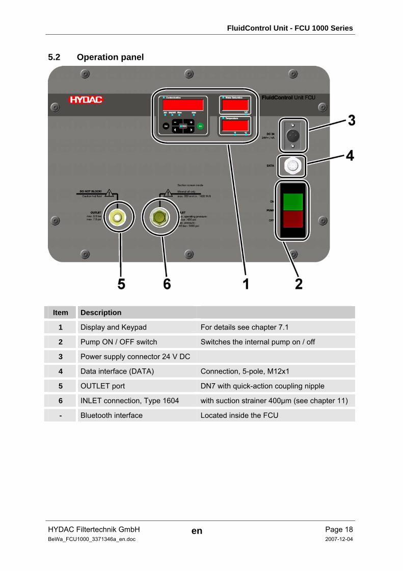
5.2 Operation panel
Item Description
1 Display and Keypad For details see chapter 7.1
2 Pump ON / OFF switch Switches the internal pump on / off
3 Power supply connector 24 V DC
4 Data interface (DATA) Connection, 5-pole, M12x1
5 OUTLET port DN7 with quick-action coupling nipple
6 INLET connection, Type 1604 with suction strainer 400µm (see chapter 11)
- Bluetooth interface Located inside the FCU
FluidControl Unit - FCU 1000 Series
HYDAC Filtertechnik GmbH en Page 19BeWa_FCU1000_3371346a_en.doc 2007-12-04
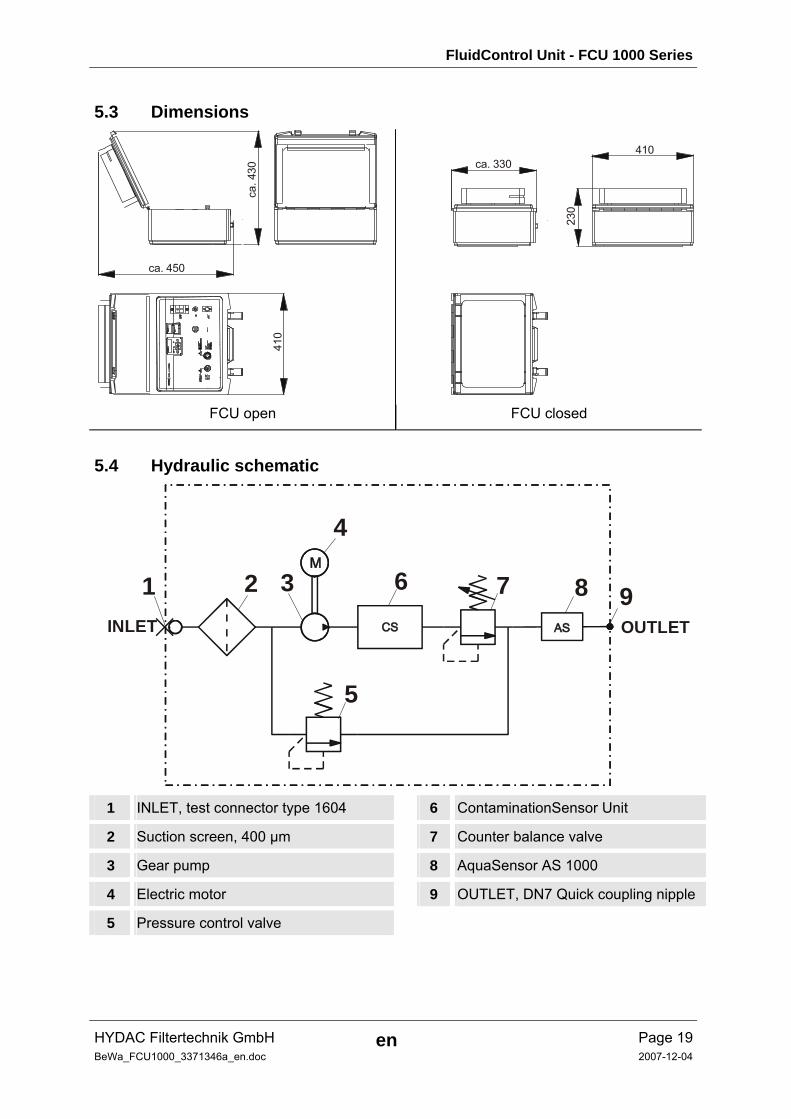
5.3 Dimensions
ca. 450
ca. 330410
230
ca. 4
30
410
FCU open FCU closed
5.4 Hydraulic schematic
INLET
1 2 3
4
6 7 8 9
5
OUTLET
1 INLET, test connector type 1604 6 ContaminationSensor Unit
2 Suction screen, 400 µm 7 Counter balance valve
3 Gear pump 8 AquaSensor AS 1000
4 Electric motor 9 OUTLET, DN7 Quick coupling nipple
5 Pressure control valve
FluidControl Unit - FCU 1000 Series
HYDAC Filtertechnik GmbH en Page 20BeWa_FCU1000_3371346a_en.doc 2007-12-04
6 Preparing the FCU Before operation, the FCU must first be hydraulically and electrically connected, as described below.
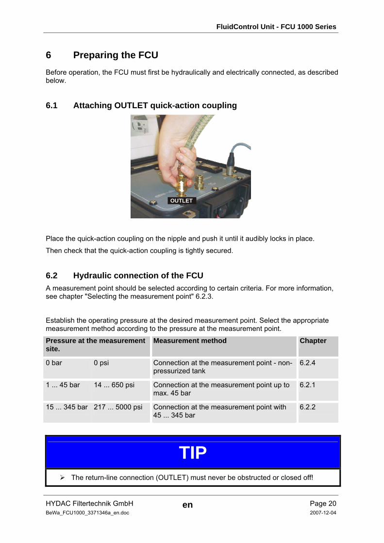
6.1 Attaching OUTLET quick-action coupling
OUTLET
Place the quick-action coupling on the nipple and push it until it audibly locks in place.
Then check that the quick-action coupling is tightly secured.
6.2 Hydraulic connection of the FCU A measurement point should be selected according to certain criteria. For more information, see chapter "Selecting the measurement point" 6.2.3.
Establish the operating pressure at the desired measurement point. Select the appropriate measurement method according to the pressure at the measurement point.
Pressure at the measurement site.
Measurement method Chapter
0 bar 0 psi Connection at the measurement point - non-pressurized tank
6.2.4
1 ... 45 bar 14 ... 650 psi Connection at the measurement point up to max. 45 bar
6.2.1
15 ... 345 bar 217 ... 5000 psi Connection at the measurement point with 45 ... 345 bar
6.2.2
TIP The return-line connection (OUTLET) must never be obstructed or closed off!

FluidControl Unit - FCU 1000 Series
HYDAC Filtertechnik GmbH en Page 21BeWa_FCU1000_3371346a_en.doc 2007-12-04
6.2.1 Connection at the measurement point up to max. 45 bar
WARNING Hydraulic systems are under pressure
Oil can start to flow through the FCU as soon as the
system has been connected to the pressure fitting.Oil can start to flow through the FCU as soon as the system has been connected to the pressure fitting.
Make sure to follow the sequence specified here
TIP The return-line connection (OUTLET) must never be obstructed or closed off!
We recommend filling the FCU before measurement. This ensures immediate and accurate measurements results. It takes approximately 120 ml of oil to completely fill the hydraulic circuit inside the FCU and INLET hose.
If the FCU is not pre-filled, an air-oil mixture will flow through the FCU at the start of measurement. The sensor will interpret the air bubbles as particles, thereby falsifying the measurement result.
For the first sampling without pre-filling the FCU and hoses, we recommend using at least 300 ml of fluid.
If the FCU is inadvertently connected to overly high pressure, the excess oil is directed to the OUTLET port.If the FCU is inadvertently connected to overly high pressure, the excess oil is directed to the OUTLET port.
Make sure to follow the sequence specified here:Make sure to follow the sequence specified here:
1. First connect the open end of the OUTLET return hose (color: clear-transparent) to the system reservoir or to a waste oil canister.
FluidControl Unit - FCU 1000 Series
HYDAC Filtertechnik GmbH en Page 22BeWa_FCU1000_3371346a_en.doc 2007-12-04
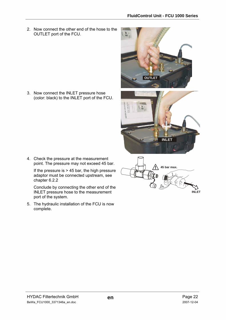
2. Now connect the other end of the hose to the OUTLET port of the FCU.
OUTLET
3. Now connect the INLET pressure hose
(color: black) to the INLET port of the FCU.
INLET
4. Check the pressure at the measurement point. The pressure may not exceed 45 bar.
If the pressure is > 45 bar, the high pressure adaptor must be connected upstream, see chapter 6.2.2
Conclude by connecting the other end of the INLET pressure hose to the measurement port of the system.
45 bar max.
INLET
5. The hydraulic installation of the FCU is now complete.
FluidControl Unit - FCU 1000 Series
HYDAC Filtertechnik GmbH en Page 23BeWa_FCU1000_3371346a_en.doc 2007-12-04
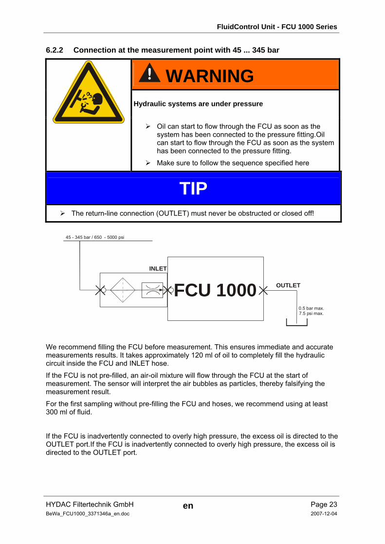
6.2.2 Connection at the measurement point with 45 ... 345 bar
WARNING Hydraulic systems are under pressure
Oil can start to flow through the FCU as soon as the
system has been connected to the pressure fitting.Oil can start to flow through the FCU as soon as the system has been connected to the pressure fitting.
Make sure to follow the sequence specified here
TIP The return-line connection (OUTLET) must never be obstructed or closed off!
INLET
FCU 1000
45 - 345 bar / 650 - 5000 psi
0.5 bar max.7.5 psi max.
OUTLET
We recommend filling the FCU before measurement. This ensures immediate and accurate measurements results. It takes approximately 120 ml of oil to completely fill the hydraulic circuit inside the FCU and INLET hose.
If the FCU is not pre-filled, an air-oil mixture will flow through the FCU at the start of measurement. The sensor will interpret the air bubbles as particles, thereby falsifying the measurement result.
For the first sampling without pre-filling the FCU and hoses, we recommend using at least 300 ml of fluid.
If the FCU is inadvertently connected to overly high pressure, the excess oil is directed to the OUTLET port.If the FCU is inadvertently connected to overly high pressure, the excess oil is directed to the OUTLET port.
FluidControl Unit - FCU 1000 Series
HYDAC Filtertechnik GmbH en Page 24BeWa_FCU1000_3371346a_en.doc 2007-12-04
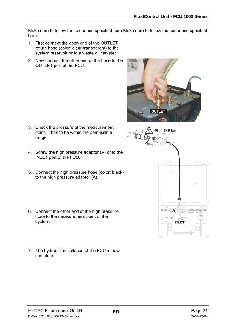
Make sure to follow the sequence specified here:Make sure to follow the sequence specified here:
1. First connect the open end of the OUTLET return hose (color: clear-transparent) to the system reservoir or to a waste oil canister.
2. Now connect the other end of the hose to the OUTLET port of the FCU.
OUTLET
3. Check the pressure at the measurement
point. It has to be within the permissible range.
4. Screw the high pressure adaptor (A) onto the INLET port of the FCU.
5. Connect the high pressure hose (color: black) to the high pressure adaptor (A).
6. Connect the other end of the high pressure hose to the measurement point of the system.
45 … 345 bar
A
INLET
7. The hydraulic installation of the FCU is now complete.
FluidControl Unit - FCU 1000 Series
HYDAC Filtertechnik GmbH en Page 25BeWa_FCU1000_3371346a_en.doc 2007-12-04
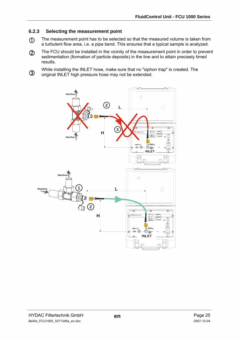
6.2.3 Selecting the measurement point
The measurement point has to be selected so that the measured volume is taken from a turbulent flow area, i.e. a pipe bend. This ensures that a typical sample is analyzed.
The FCU should be installed in the vicinity of the measurement point in order to prevent sedimentation (formation of particle deposits) in the line and to attain precisely timed results.
While installing the INLET hose, make sure that no "siphon trap" is created. The original INLET high pressure hose may not be extended.
3H
L2
INLET
Mainflow
Mainflow
H
Mainflow
Mainflow L1
2
INLET
FluidControl Unit - FCU 1000 Series
HYDAC Filtertechnik GmbH en Page 26BeWa_FCU1000_3371346a_en.doc 2007-12-04
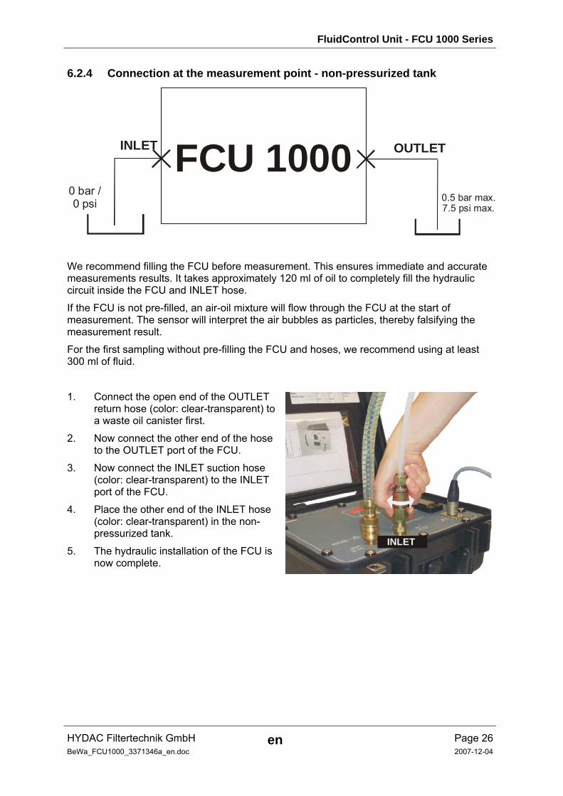
6.2.4 Connection at the measurement point - non-pressurized tank
INLET FCU 10000.5 bar max.7.5 psi max.
OUTLET
0 bar /0 psi
We recommend filling the FCU before measurement. This ensures immediate and accurate measurements results. It takes approximately 120 ml of oil to completely fill the hydraulic circuit inside the FCU and INLET hose.
If the FCU is not pre-filled, an air-oil mixture will flow through the FCU at the start of measurement. The sensor will interpret the air bubbles as particles, thereby falsifying the measurement result.
For the first sampling without pre-filling the FCU and hoses, we recommend using at least 300 ml of fluid.
1. Connect the open end of the OUTLET return hose (color: clear-transparent) to a waste oil canister first.
2. Now connect the other end of the hose to the OUTLET port of the FCU.
3. Now connect the INLET suction hose (color: clear-transparent) to the INLET port of the FCU.
4. Place the other end of the INLET hose (color: clear-transparent) in the non-pressurized tank.
5. The hydraulic installation of the FCU is now complete.
INLET
FluidControl Unit - FCU 1000 Series
HYDAC Filtertechnik GmbH en Page 27BeWa_FCU1000_3371346a_en.doc 2007-12-04
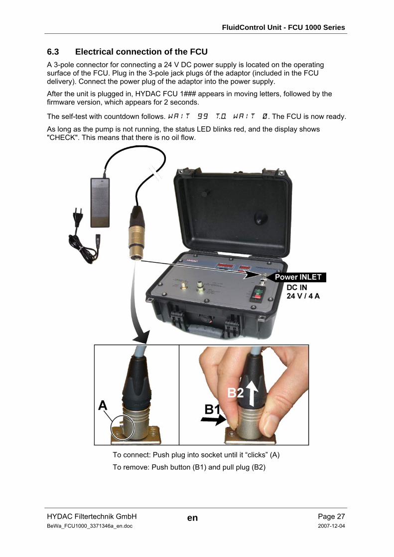
6.3 Electrical connection of the FCU A 3-pole connector for connecting a 24 V DC power supply is located on the operating surface of the FCU. Plug in the 3-pole jack plugs óf the adaptor (included in the FCU delivery). Connect the power plug of the adaptor into the power supply.
After the unit is plugged in, HYDAC FCU 1### appears in moving letters, followed by the firmware version, which appears for 2 seconds.
The self-test with countdown follows. WAIT 99 to WAIT 0. The FCU is now ready.
As long as the pump is not running, the status LED blinks red, and the display shows "CHECK". This means that there is no oil flow.
To connect: Push plug into socket until it “clicks” (A)
To remove: Push button (B1) and pull plug (B2)

FluidControl Unit - FCU 1000 Series
HYDAC Filtertechnik GmbH en Page 28BeWa_FCU1000_3371346a_en.doc 2007-12-04
7 Operating the FCU As soon as the FCU 1000 is switched on, HYDAC FCU 1### appears in the display in moving letters, followed by the firmware version, which is illuminated for 2 seconds.
This is followed by a countdown: WAIT 99 to WAIT 0. The duration of the countdown corresponds to the set measurement time (factory setting = 30 sec). This means that the countdown runs from 99 - 0 within the set measurement time.
7.1 Display and keypad elements
Item LED Description
A Status Indicates the status of the Contamination Sensor (for details see chapter 12 )
B Display Consists of a 6-digit display and shows the selected measured values.
C Measured variable Indicates the measured variable that is shown in the display, i.e. ISO / SAE / NAS
D Additional variable Indicates the additional variable that is shown in the display , i.e.: Flow / Drive
E Display active Only the display where the active LED is illuminated can be operated by the keypad. See chapter 7.1.3
F Unit (of measurement)
The temperature display can be set to °C or °F units
FluidControl Unit - FCU 1000 Series
HYDAC Filtertechnik GmbH en Page 29BeWa_FCU1000_3371346a_en.doc 2007-12-04
The keyboard consists of six buttons. These buttons are used to operate the FCU and to navigate through the menus (hierarchically structured).
Keyboard Description
o.k.
- one level down - confirm changed value (lowest level) - confirm when changes are to be saved or canceled (top level)
Esc
- one level up - no value change
+
- change value at the lowest level (when display is blinking)
- scroll through display
- scroll through menu
- select digit
7.1.1 Measured variables The measurement variables provide the user information about the cleanliness (or contamination) of the oil in his facility. The measurement variables are calibrated. They indicate a measured value with an accuracy of +/- 1/2 codes/class.
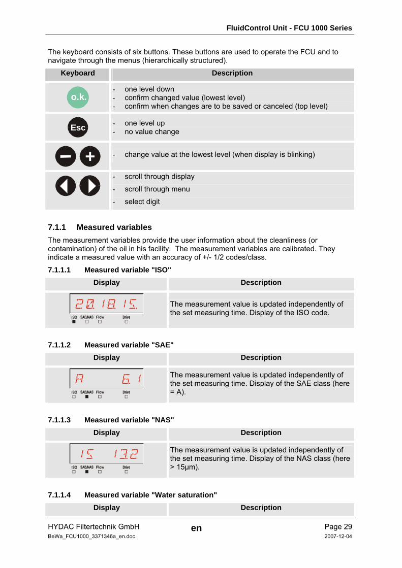
7.1.1.1 Measured variable "ISO" Display Description
2=1(1%
The measurement value is updated independently of the set measuring time. Display of the ISO code.
7.1.1.2 Measured variable "SAE" Display Description
A &1
The measurement value is updated independently of the set measuring time. Display of the SAE class (here = A).
7.1.1.3 Measured variable "NAS" Display Description
15 1§2
The measurement value is updated independently of the set measuring time. Display of the NAS class (here > 15µm).
7.1.1.4 Measured variable "Water saturation" Display Description
FluidControl Unit - FCU 1000 Series
HYDAC Filtertechnik GmbH en Page 30BeWa_FCU1000_3371346a_en.doc 2007-12-04
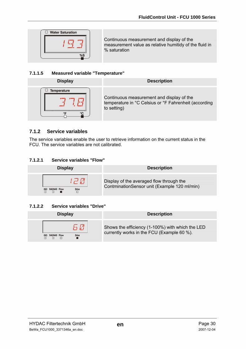
1)3
Continuous measurement and display of the measurement value as relative humitidy of the fluid in % saturation
7.1.1.5 Measured variable "Temperature" Display Description
3/8
Continuous measurement and display of the temperature in °C Celsius or °F Fahrenheit (according to setting)
7.1.2 Service variables The service variables enable the user to retrieve information on the current status in the FCU. The service variables are not calibrated.
7.1.2.1 Service variables "Flow" Display Description
120
Display of the averaged flow through the ContminationSensor unit (Example 120 ml/min)
7.1.2.2 Service variables "Drive" Display Description
60
Shows the efficiency (1-100%) with which the LED currently works in the FCU (Example 60 %).
FluidControl Unit - FCU 1000 Series
HYDAC Filtertechnik GmbH en Page 31BeWa_FCU1000_3371346a_en.doc 2007-12-04
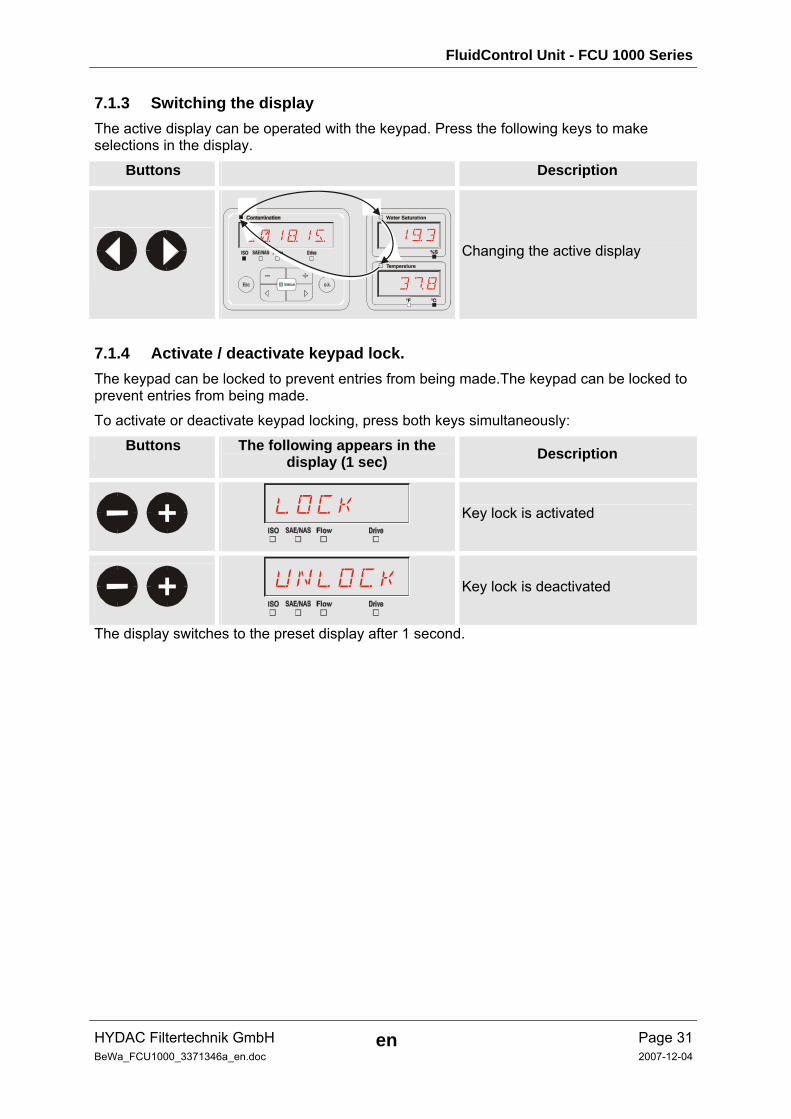
7.1.3 Switching the display The active display can be operated with the keypad. Press the following keys to make selections in the display.
Buttons Description
2=1(1%
3/8
1)3Changing the active display
7.1.4 Activate / deactivate keypad lock. The keypad can be locked to prevent entries from being made.The keypad can be locked to prevent entries from being made.
To activate or deactivate keypad locking, press both keys simultaneously:
Buttons The following appears in the display (1 sec) Description
+
LOCK
Key lock is activated
+
UNLOCK
Key lock is deactivated
The display switches to the preset display after 1 second.
FluidControl Unit - FCU 1000 Series
HYDAC Filtertechnik GmbH en Page 32BeWa_FCU1000_3371346a_en.doc 2007-12-04
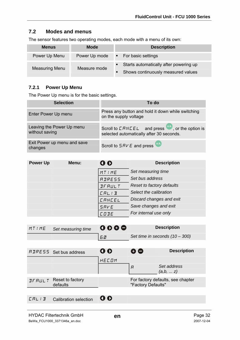
7.2 Modes and menus The sensor features two operating modes, each mode with a menu of its own:
Menus Mode Description
Power Up Menu Power Up mode For basic settings
Measuring Menu Measure mode Starts automatically after powering up
Shows continuously measured values
7.2.1 Power Up Menu The Power Up menu is for the basic settings.
Selection To do
Enter Power Up menu Press any button and hold it down while switching on the supply voltage
Leaving the Power Up menu without saving
Scroll to CANCEL and press o.k. , or the option is selected automatically after 30 seconds.
Exit Power up menu and save changes Scroll to SAVE and press o.k.
Power Up Menu: Description
mTIME Set measuring time ADRESS Set bus address DFAULT Reset to factory defaults CAlIb Select the calibration CANCEL Discard changes and exit SAVE Save changes and exit CODE For internal use only
mTIME Set measuring time + Description
60 Set time in seconds (10 – 300)
ADRESS Set bus address + Description
HECOM A Set address
(a,b, ... z)
DFAULT Reset to factory defaults
For factory defaults, see chapter "Factory Defaults"
CALIB Calibration selection
FluidControl Unit - FCU 1000 Series
HYDAC Filtertechnik GmbH en Page 33BeWa_FCU1000_3371346a_en.doc 2007-12-04
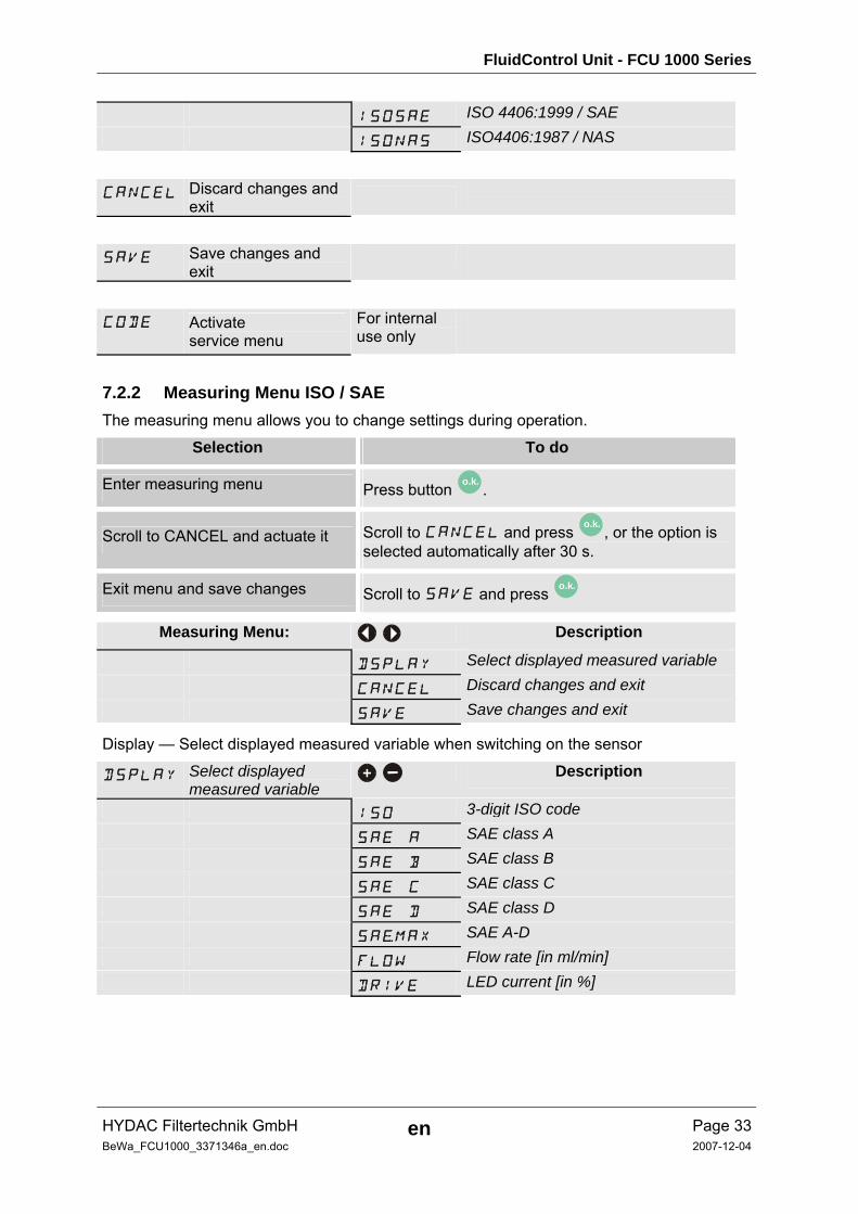
ISOSAE ISO 4406:1999 / SAE ISONAS ISO4406:1987 / NAS
CANCEL Discard changes and exit
SAVE Save changes and exit
CODE Activate service menu
For internal use only
7.2.2 Measuring Menu ISO / SAE The measuring menu allows you to change settings during operation.
Selection To do
Enter measuring menu Press button o.k. .
Scroll to CANCEL and actuate it Scroll to CANCEL and press o.k. , or the option is selected automatically after 30 s.
Exit menu and save changes Scroll to SAVE and press o.k.
Measuring Menu: Description
DSPLAY Select displayed measured variable CANCEL Discard changes and exit SAVE Save changes and exit
Display — Select displayed measured variable when switching on the sensor
DSPLAY Select displayed measured variable
+ Description
ISO 3-digit ISO code SAE A SAE class A SAE B SAE class B SAE C SAE class C SAE D SAE class D SAeMAX SAE A-D FLOW Flow rate [in ml/min] DRIVE LED current [in %]
FluidControl Unit - FCU 1000 Series
HYDAC Filtertechnik GmbH en Page 34BeWa_FCU1000_3371346a_en.doc 2007-12-04
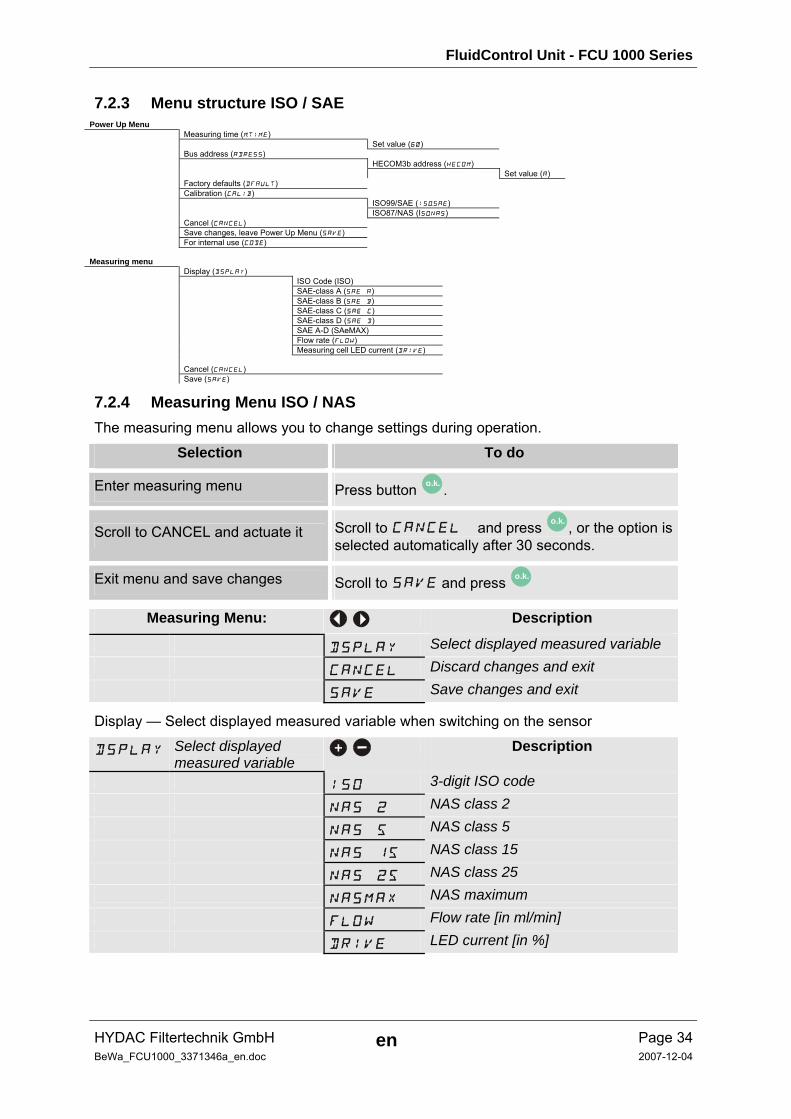
7.2.3 Menu structure ISO / SAE Power Up Menu Measuring time (mTIME) Set value (60) Bus address (ADRESS) HECOM3b address (HECOM) Set value (A) Factory defaults (DFAULT) Calibration (CALIB) ISO99/SAE (ISoSAE) ISO87/NAS (ISoNAS) Cancel (CANCEL) Save changes, leave Power Up Menu (SAVE) For internal use (CODE) Measuring menu Display (DSPLAY) ISO Code (ISO) SAE-class A (SAE A) SAE-class B (SAE B) SAE-class C (SAE C) SAE-class D (SAE D) SAE A-D (SAeMAX) Flow rate (FLOW) Measuring cell LED current (DRIVE) Cancel (CANCEL) Save (SAVE)
7.2.4 Measuring Menu ISO / NAS The measuring menu allows you to change settings during operation.
Selection To do
Enter measuring menu Press button o.k. .
Scroll to CANCEL and actuate it Scroll to CANCEL and press o.k. , or the option is selected automatically after 30 seconds.
Exit menu and save changes Scroll to SAVE and press o.k.
Measuring Menu: Description
DSPLAY Select displayed measured variable CANCEL Discard changes and exit SAVE Save changes and exit
Display — Select displayed measured variable when switching on the sensor
DSPLAY Select displayed measured variable
+ Description
ISO 3-digit ISO code NAS 2 NAS class 2 NAS 5 NAS class 5 NAS 15 NAS class 15 NAS 25 NAS class 25 NASMAX NAS maximum FLOW Flow rate [in ml/min] DRIVE LED current [in %]

FluidControl Unit - FCU 1000 Series
HYDAC Filtertechnik GmbH en Page 35BeWa_FCU1000_3371346a_en.doc 2007-12-04
7.2.5 Menu structure ISO / NAS Power Up Menu Measuring time (mTIME) Set value (60) Bus address (ADRESS) HECOM3b address (HECOM) Set value (A) Factory defaults (DFAULT) Calibration selection (CALIB) ISO99/SAE (ISoSAE) ISO87/NAS (ISoNAS) Cancel (CANCEL) Save changes, leave Power Up Menu (SAVE) For internal use (CODE) Measuring menu Display (DSPLAY) ISO Code (ISO) NAS-class 2 (NAS 2) NAS-class 5 (NAS 5) NAS-class 15 (NAS 15) NAS-class 25 (NAS 25) NAS Maximum (NAsMAX) Flow rate (FLOW) Measuring cell LED current (DRIVE) Cancel (CANCEL) Save (SAVE)
8 Performing a measurement 1. Check all the hydraulic and electrical connections to the FCU.
2. Now press the green "Pump ON" switch.
3. Now the pump feeds oil through the FCU. After the set measurement time, the result is shown on the display, and the status LED lights up green permanently.
8.1 Restrictions pertaining to use
TIP The FCU 1000 Series may only be used with mineral oils or mineral oil-based
raffinates.
Permissible viscosity range: 10 – 350 mm²/s or 46 – 1622 SUS (ISO VG 68)
The FCU 1000 is designed for short time operation and NOT for continuous operation (S4 according to DIN EN 60034 / VDE 0530). After 30 minutes of permanent pump operation, the pump must be shut off for at least 10 minutes.
FluidControl Unit - FCU 1000 Series
HYDAC Filtertechnik GmbH en Page 36BeWa_FCU1000_3371346a_en.doc 2007-12-04
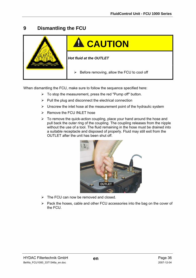
9 Dismantling the FCU
CAUTION Hot fluid at the OUTLET
Before removing, allow the FCU to cool off
When dismantling the FCU, make sure to follow the sequence specified here:
To stop the measurement, press the red "Pump off" button.
Pull the plug and disconnect the electrical connection
Unscrew the inlet hose at the measurement point of the hydraulic system
Remove the FCU INLET hose
To remove the quick-action coupling, place your hand around the hose and pull back the outer ring of the coupling. The coupling releases from the nipple without the use of a tool. The fluid remaining in the hose must be drained into a suitable receptacle and disposed of properly. Fluid may still exit from the OUTLET after the unit has been shut off.
OUTLET
The FCU can now be removed and closed.
Pack the hoses, cable and other FCU accessories into the bag on the cover of the FCU.
FluidControl Unit - FCU 1000 Series
HYDAC Filtertechnik GmbH en Page 37BeWa_FCU1000_3371346a_en.doc 2007-12-04
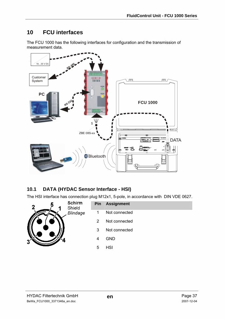
10 FCU interfaces The FCU 1000 has the following interfaces for configuration and the transmission of measurement data.
CS 1
000
RS 232
RS 485
RS 232
18…35 V DC
CustomerSystem
PC
ZBE 08S-xx
5
FCU 1000
Bluetooth
DATA
10.1 DATA (HYDAC Sensor Interface - HSI) The HSI interface has connection plug M12x1, 5-pole, in accordance with DIN VDE 0627.
Pin Assignment
1 Not connected
2 Not connected
3 Not connected
4 GND 5 HSI
FluidControl Unit - FCU 1000 Series
HYDAC Filtertechnik GmbH en Page 38BeWa_FCU1000_3371346a_en.doc 2007-12-04
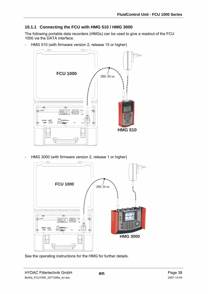
10.1.1 Connecting the FCU with HMG 510 / HMG 3000 The following portable data recorders (HMGs) can be used to give a readout of the FCU 1000 via the DATA interface.
- HMG 510 (with firmware version 2, release 15 or higher)
ZBE 30-xxFCU 1000
HMG 510
- HMG 3000 (with firmware version 2, release 1 or higher)
HMG 3000
ZBE 30-xxFCU 1000
See the operating instructions for the HMG for further details.
FluidControl Unit - FCU 1000 Series
HYDAC Filtertechnik GmbH en Page 39BeWa_FCU1000_3371346a_en.doc 2007-12-04
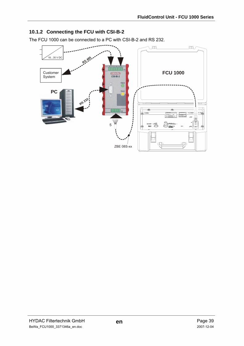
10.1.2 Connecting the FCU with CSI-B-2 The FCU 1000 can be connected to a PC with CSI-B-2 and RS 232.
CS 1
000
RS 232
RS 485
RS 232
18…35 V DC
CustomerSystem
PC
ZBE 08S-xx
5
FCU 1000
FluidControl Unit - FCU 1000 Series
HYDAC Filtertechnik GmbH en Page 40BeWa_FCU1000_3371346a_en.doc 2007-12-04
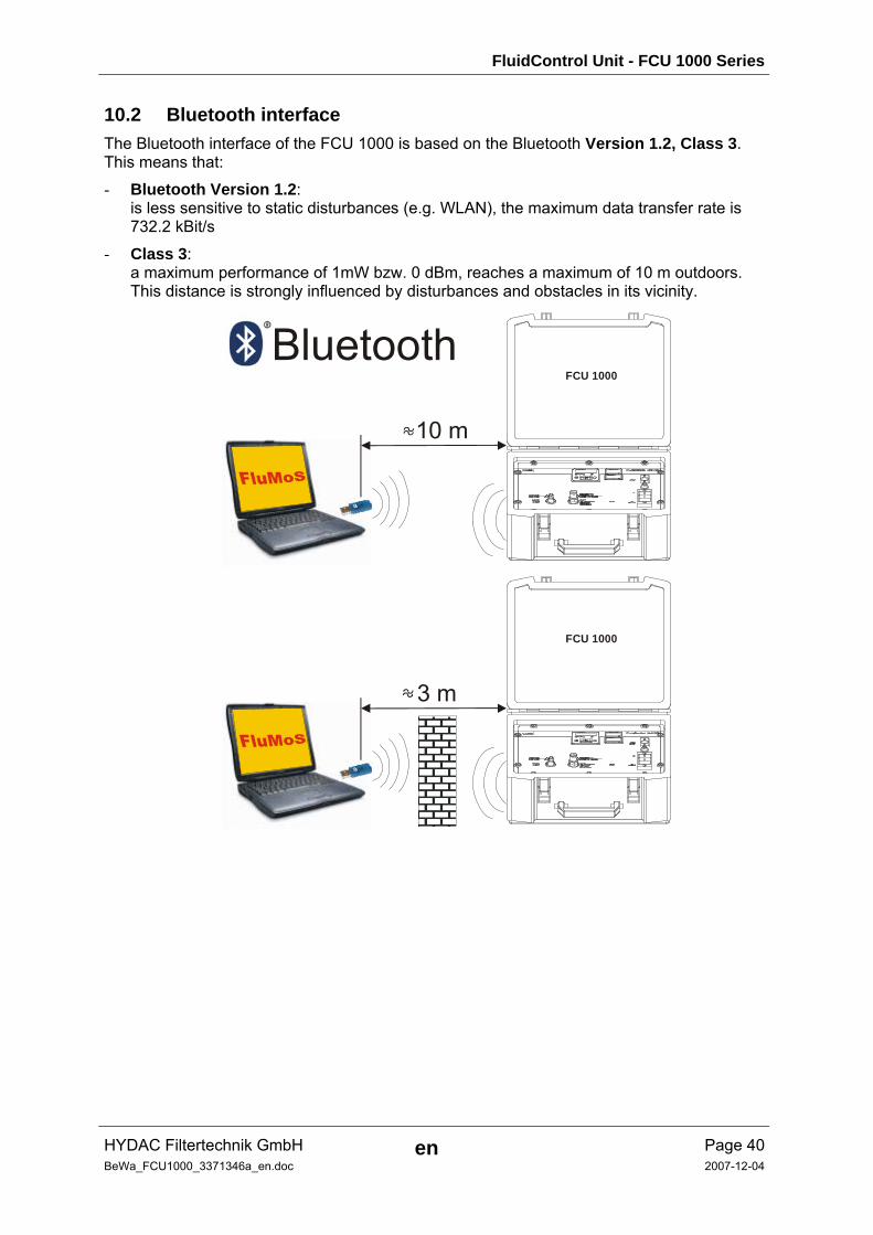
10.2 Bluetooth interface The Bluetooth interface of the FCU 1000 is based on the Bluetooth Version 1.2, Class 3. This means that: - Bluetooth Version 1.2:
is less sensitive to static disturbances (e.g. WLAN), the maximum data transfer rate is 732.2 kBit/s
- Class 3: a maximum performance of 1mW bzw. 0 dBm, reaches a maximum of 10 m outdoors. This distance is strongly influenced by disturbances and obstacles in its vicinity.
FCU 1000
FCU 1000
Bluetooth
10 m
3 m
FluidControl Unit - FCU 1000 Series
HYDAC Filtertechnik GmbH en Page 41BeWa_FCU1000_3371346a_en.doc 2007-12-04
10.2.1 Installing the Bluetooth USB adaptor If the PC already has a Bluetooth interface, use this only to establish a connection to the FCU - See chapter 10.2.2.
Prior to the installation of new Bluetooth software, we strongly recommend deinstalling all existing Bluetooth drivers. The parallel use of different Bluetooth interfaces leads to diver conflicts.
If problems should arise, consult the Bluetooth USB adaptor handbook or consult the manufacturer of your PC hardware.
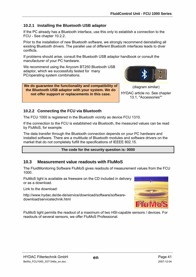
We recommend using the Anycom BT250 Bluetooth USB adaptor, which we successfully tested for many PC/operating system combinations.
We do guarantee the functionality and compatibility of the Bluetooth USB adaptor with your system. We do
not offer support or replacements in this case.
(diagram similar)
HYDAC article no. See chapter 13.1, "Accessories"“
10.2.2 Connecting the FCU via Bluetooth The FCU 1000 is registered in the Bluetooth vicinity as device FCU 1310.
If the connection to the FCU is established via Bluetooth, the measured values can be read by FluMoS, for example.
The data transfer through the Bluetooth connection depends on your PC hardware and installed software. There are a multitude of Bluetooth modules and software drivers on the market that do not completely fulfill the specifications of IEEEE 802.15.
The code for the security question is: 0000
10.3 Measurement value readouts with FluMoS The FluidMonitoring Software FluMoS gives readouts of measurement values from the FCU 1000.
FluMoS light is available as freeware on the CD included in delivery or as a download.
Link to the download:
http://www.hydac.de/de-de/service/download/software/software-download/servicetechnik.html
FluMoS light permits the readout of a maximum of two HSI-capable sensors / devices. For readouts of several sensors, we offer FluMoS Professional.
FluidControl Unit - FCU 1000 Series
HYDAC Filtertechnik GmbH en Page 42BeWa_FCU1000_3371346a_en.doc 2007-12-04
11 Conducing maintenance Conduct the suggested maintenance/servicing and inspection work every six months, or if an error indication recommends it.
All operating media are to be protected/isolated in case the product is accidentally started up.
When performing any maintenance, servicing, inspection or repair work, disconnect the FCU from the power supply and ensure that it cannot be switched back on inadvertently.
Always check the product to see that it functions properly when performing maintenance and servicing work.
Check any screw fittings which have been removed to see that they have been properly secured.
11.1 Cleaning the FCU When cleaning the operating surface, we recommend rubbing it using a clean, wet cloth, making sure that no residue is left.
11.2 Rinsing the FCU Flush the FCU 1000 after each use or daily with appropriate mineral oil.
11.2.1 Performing a rinsing The FCU 1000 should be flushed (cleaned) after each use.
Rinsing the FCU is especially critical when non-filtered oil or 50 W or heavier viscosity oil has been sampled. Rinsing should also be performed when the operator observes any measured values which appear abnormally high or low.
Always rinse the FCU after the last system cleanliness check of the day.
1. Fill a suitable clean container with 500 ml of filtered oil.
2. Connect the return flow hose from the OUTLET and place it into a waste container / canister for used fluids.
3. Place the suction hose in the container with the filtered oil.
4. Now switch on the FCU.
5. Cleanliness values are displayed during the rinsing procedure. These values are not correct, but should decrease during the rinsing procedure.
6. After the FCU has been completely flushed out, shut it off.
7. Now the unit is ready for operation!
FluidControl Unit - FCU 1000 Series
HYDAC Filtertechnik GmbH en Page 43BeWa_FCU1000_3371346a_en.doc 2007-12-04
11.3 Cleaning the suction strainer A suction screen is fitted under the INLET measurement point union and protects the pump from coarse-particle contamination.
The suction strainer must be cleaned at regular intervals according to the prescribed maintenance intervals. The suction strainer is blocked when no flow exits the FCU.
TIP If the FCU does not pump any fluid, the suction strainer should be checked and cleaned if necessary. Operating the FCU without a suction strainer can lead to malfunction.
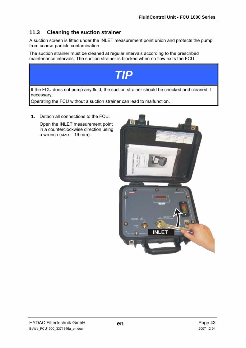
1. Detach all connections to the FCU.
Open the INLET measurement point in a counterclockwise direction using a wrench (size = 19 mm).
INLET
FluidControl Unit - FCU 1000 Series
HYDAC Filtertechnik GmbH en Page 44BeWa_FCU1000_3371346a_en.doc 2007-12-04
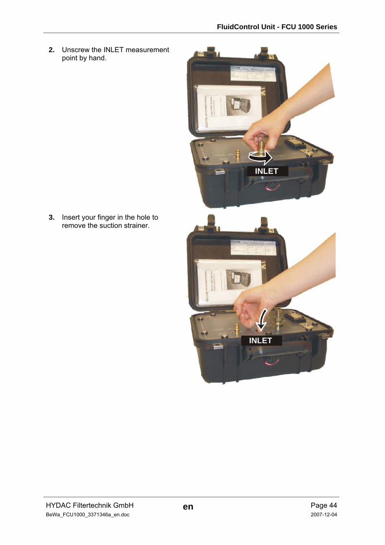
2. Unscrew the INLET measurement point by hand.
INLET
3. Insert your finger in the hole to remove the suction strainer.
INLET
FluidControl Unit - FCU 1000 Series
HYDAC Filtertechnik GmbH en Page 45BeWa_FCU1000_3371346a_en.doc 2007-12-04
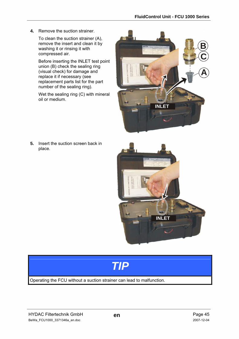
4. Remove the suction strainer.
To clean the suction strainer (A), remove the insert and clean it by washing it or rinsing it with compressed air.
Before inserting the INLET test point union (B) check the sealing ring (visual check) for damage and replace it if necessary (see replacement parts list for the part number of the sealing ring).
Wet the sealing ring (C) with mineral oil or medium.
INLET
A
BC
5. Insert the suction screen back in place.
INLET
TIP Operating the FCU without a suction strainer can lead to malfunction.

FluidControl Unit - FCU 1000 Series
HYDAC Filtertechnik GmbH en Page 46BeWa_FCU1000_3371346a_en.doc 2007-12-04
6. Insert the INLET test point union by hand and screw it in by turning it in a clockwise direction.
INLET
7. Screw the INLET test point union tight using a wrench (size = 19 mm / ¾ inch) by turning it in a clockwise direction.
INLET
max. 25 Nm
FluidControl Unit - FCU 1000 Series
HYDAC Filtertechnik GmbH en Page 47BeWa_FCU1000_3371346a_en.doc 2007-12-04
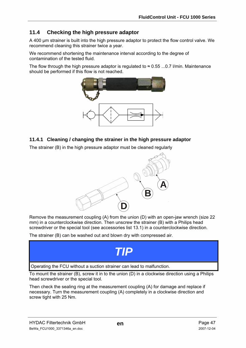
11.4 Checking the high pressure adaptor A 400 µm strainer is built into the high pressure adaptor to protect the flow control valve. We recommend cleaning this strainer twice a year.
We recommend shortening the maintenance interval according to the degree of contamination of the tested fluid.
The flow through the high pressure adaptor is regulated to ≈ 0.55 ...0.7 l/min. Maintenance should be performed if this flow is not reached.
11.4.1 Cleaning / changing the strainer in the high pressure adaptor The strainer (B) in the high pressure adaptor must be cleaned regularly
BD
A
Remove the measurement coupling (A) from the union (D) with an open-jaw wrench (size 22 mm) in a counterclockwise direction. Then unscrew the strainer (B) with a Philips head screwdriver or the special tool (see accessories list 13.1) in a counterclockwise direction.
The strainer (B) can be washed out and blown dry with compressed air.
TIP Operating the FCU without a suction strainer can lead to malfunction.
To mount the strainer (B), screw it in to the union (D) in a clockwise direction using a Philips head screwdriver or the special tool.
Then check the sealing ring at the measurement coupling (A) for damage and replace if necessary. Turn the measurement coupling (A) completely in a clockwise direction and screw tight with 25 Nm.
FluidControl Unit - FCU 1000 Series
HYDAC Filtertechnik GmbH en Page 48BeWa_FCU1000_3371346a_en.doc 2007-12-04
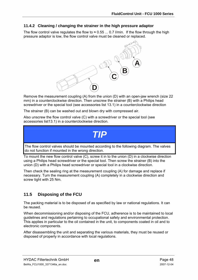
11.4.2 Cleaning / changing the strainer in the high pressure adaptor The flow control valve regulates the flow to ≈ 0.55 ... 0.7 l/min. If the flow through the high pressure adaptor is low, the flow control valve must be cleaned or replaced.
BA
CD
Remove the measurement coupling (A) from the union (D) with an open-jaw wrench (size 22 mm) in a counterclockwise direction. Then unscrew the strainer (B) with a Philips head screwdriver or the special tool (see accessories list 13.1) in a counterclockwise direction
The strainer (B) can be washed out and blown dry with compressed air.
Also unscrew the flow control valve (C) with a screwdriver or the special tool (see accessories list13.1) in a counterclockwise direction.
TIP The flow control valves should be mounted according to the following diagram. The valves do not function if mounted in the wrong direction.
To mount the new flow control valve (C), screw it in to the union (D) in a clockwise direction using a Philips head screwdriver or the special tool. Then screw the strainer (B) into the union (D) with a Philips head screwdriver or special tool in a clockwise direction.
Then check the sealing ring at the measurement coupling (A) for damage and replace if necessary. Turn the measurement coupling (A) completely in a clockwise direction and screw tight with 25 Nm.
11.5 Disposing of the FCU
The packing material is to be disposed of as specified by law or national regulations. It can be reused.
When decommissioning and/or disposing of the FCU, adherence is to be maintained to local guidelines and regulations pertaining to occupational safety and environmental protection. This applies in particular to the oil contained in the unit, to components coated in oil and to electronic components.
After disassembling the unit and separating the various materials, they must be reused or disposed of properly in accordance with local regulations.
FluidControl Unit - FCU 1000 Series
HYDAC Filtertechnik GmbH en Page 49BeWa_FCU1000_3371346a_en.doc 2007-12-04
12 FCU status messages
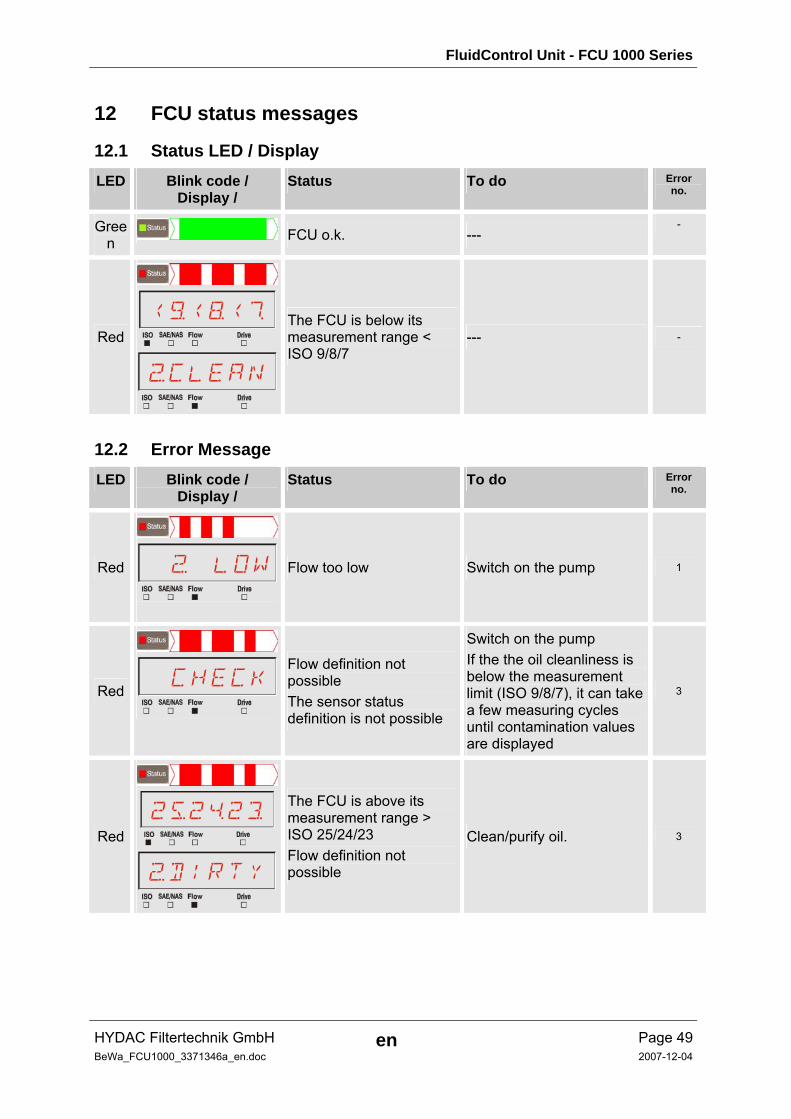
12.1 Status LED / Display LED Blink code /
Display / Status To do Error
no.
Green FCU o.k. ---
-
Red
<)<(</
“CLEAN
The FCU is below its measurement range < ISO 9/8/7
--- -
12.2 Error Message LED Blink code /
Display / Status To do Error
no.
Red
“ LOW
Flow too low Switch on the pump 1
Red
CHECK
Flow definition not possible The sensor status definition is not possible
Switch on the pump If the the oil cleanliness is below the measurement limit (ISO 9/8/7), it can take a few measuring cycles until contamination values are displayed
3
Red
2%2$2§
“DIRTY
The FCU is above its measurement range > ISO 25/24/23 Flow definition not possible
Clean/purify oil. 3
FluidControl Unit - FCU 1000 Series
HYDAC Filtertechnik GmbH en Page 50BeWa_FCU1000_3371346a_en.doc 2007-12-04
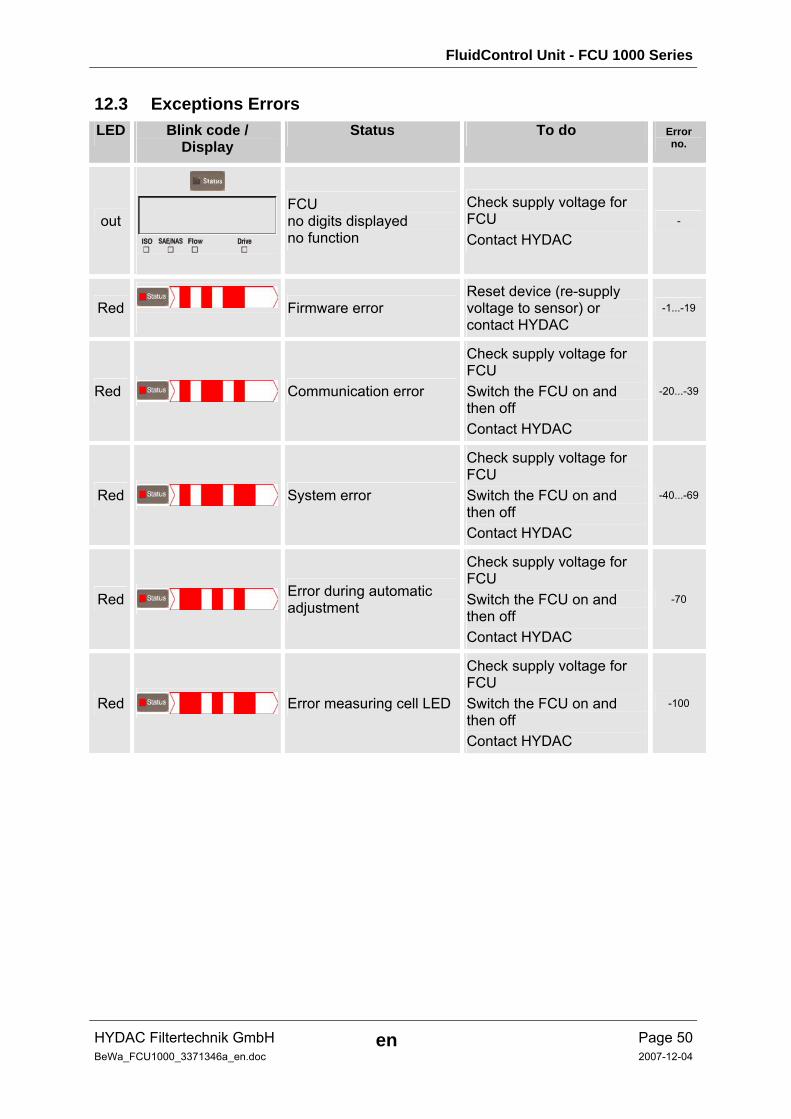
12.3 Exceptions Errors LED Blink code /
Display Status To do Error
no.
out
FCU no digits displayed no function
Check supply voltage for FCU Contact HYDAC
-
Red
Firmware error Reset device (re-supply voltage to sensor) or contact HYDAC
-1...-19
Red Communication error
Check supply voltage for FCU Switch the FCU on and then off Contact HYDAC
-20...-39
Red System error
Check supply voltage for FCU Switch the FCU on and then off Contact HYDAC
-40...-69
Red Error during automatic adjustment
Check supply voltage for FCU Switch the FCU on and then off Contact HYDAC
-70
Red Error measuring cell LED
Check supply voltage for FCU Switch the FCU on and then off Contact HYDAC
-100
FluidControl Unit - FCU 1000 Series
HYDAC Filtertechnik GmbH en Page 51BeWa_FCU1000_3371346a_en.doc 2007-12-04
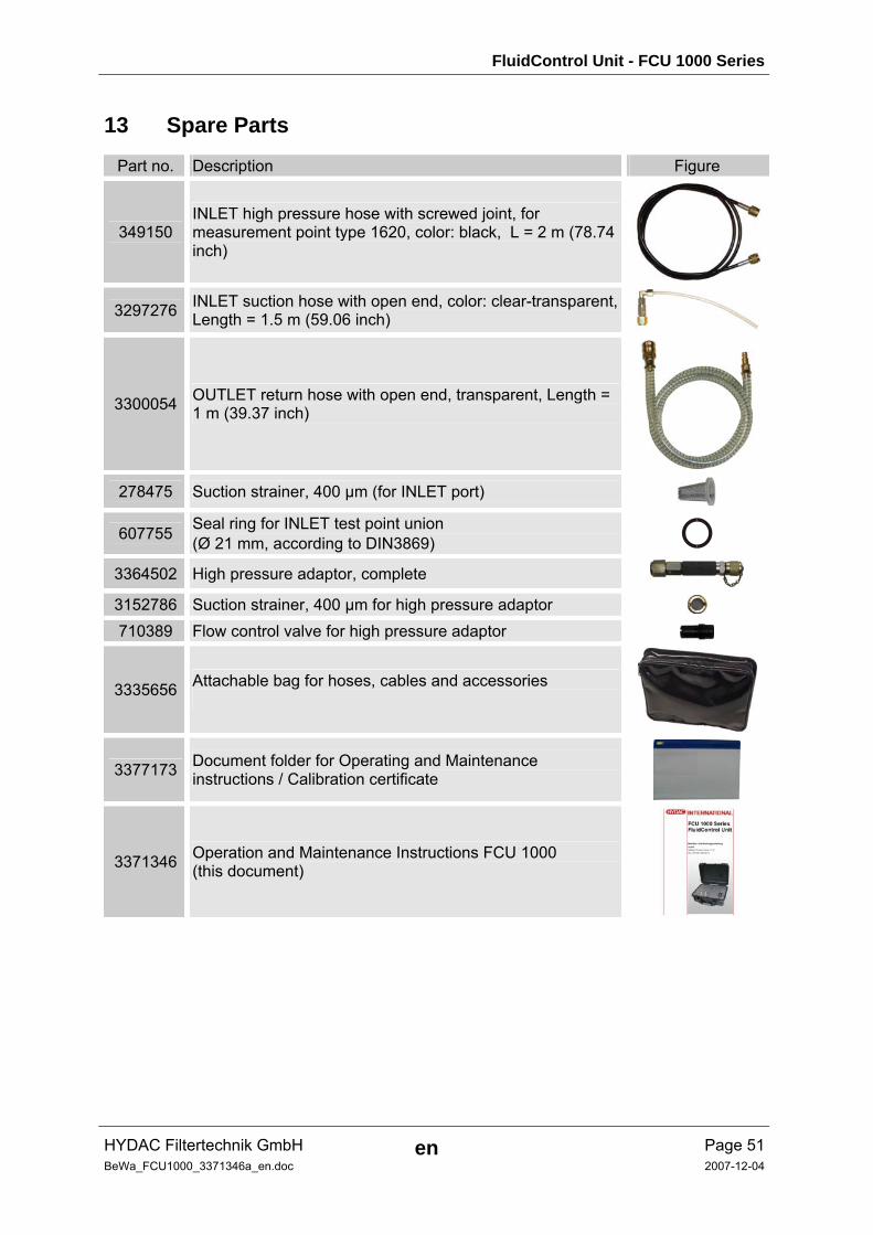
13 Spare Parts
Part no. Description Figure
349150 INLET high pressure hose with screwed joint, for measurement point type 1620, color: black, L = 2 m (78.74 inch)
3297276 INLET suction hose with open end, color: clear-transparent, Length = 1.5 m (59.06 inch)
3300054 OUTLET return hose with open end, transparent, Length = 1 m (39.37 inch)
278475 Suction strainer, 400 µm (for INLET port)
607755 Seal ring for INLET test point union (Ø 21 mm, according to DIN3869)
3364502 High pressure adaptor, complete 3152786 Suction strainer, 400 µm for high pressure adaptor 710389 Flow control valve for high pressure adaptor
3335656 Attachable bag for hoses, cables and accessories
3377173 Document folder for Operating and Maintenance instructions / Calibration certificate
3371346 Operation and Maintenance Instructions FCU 1000 (this document)

FluidControl Unit - FCU 1000 Series
HYDAC Filtertechnik GmbH en Page 52BeWa_FCU1000_3371346a_en.doc 2007-12-04
Part no. Description Figure
6059933 Power adaptor (without power cord) primary: 100-240 V AC secondary: 24 V DC, 5A, cable with 3-pole plug, Length = 1.6 m (62.99 inch)
6008448 Connection cable for power adaptor European plug, Length = 2 m (78.74 inch)
6008447 Connection cable for power adaptor plug for England (UK), Length = 2 m (78,74 inch)
6008446 Connection cable for power adaptor plug for USA, Length = 2 m (78.74 inch)
6008449 Connection cable for power adaptor plug for Australia (AUS), Length = 2 m (78.74 inch)
FluidControl Unit - FCU 1000 Series
HYDAC Filtertechnik GmbH en Page 53BeWa_FCU1000_3371346a_en.doc 2007-12-04
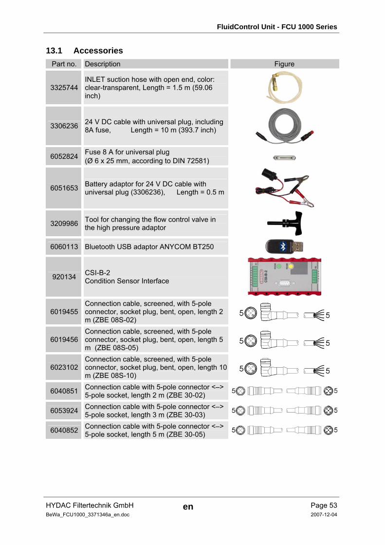
13.1 Accessories Part no. Description Figure
3325744 INLET suction hose with open end, color: clear-transparent, Length = 1.5 m (59.06 inch)
3306236 24 V DC cable with universal plug, including 8A fuse, Length = 10 m (393.7 inch)
6052824 Fuse 8 A for universal plug (Ø 6 x 25 mm, according to DIN 72581)
6051653 Battery adaptor for 24 V DC cable with universal plug (3306236), Length = 0.5 m
3209986 Tool for changing the flow control valve in the high pressure adaptor
6060113 Bluetooth USB adaptor ANYCOM BT250
920134 CSI-B-2 Condition Sensor Interface
6019455 Connection cable, screened, with 5-pole connector, socket plug, bent, open, length 2 m (ZBE 08S-02)
6019456 Connection cable, screened, with 5-pole connector, socket plug, bent, open, length 5 m (ZBE 08S-05)
6023102 Connection cable, screened, with 5-pole connector, socket plug, bent, open, length 10 m (ZBE 08S-10)
6040851 Connection cable with 5-pole connector <–> 5-pole socket, length 2 m (ZBE 30-02)
6053924 Connection cable with 5-pole connector <–> 5-pole socket, length 3 m (ZBE 30-03)
6040852 Connection cable with 5-pole connector <–> 5-pole socket, length 5 m (ZBE 30-05)
FluidControl Unit - FCU 1000 Series
HYDAC Filtertechnik GmbH en Page 54BeWa_FCU1000_3371346a_en.doc 2007-12-04
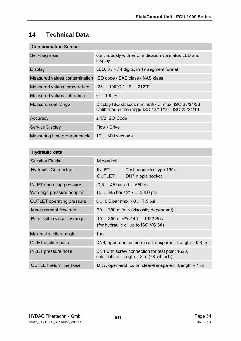
14 Technical Data
Contamination Sensor
Self-diagnosis continuously with error indication via status LED and display
Display LED, 6 / 4 / 4 digits, in 17 segment format
Measured values contamination ISO code / SAE class / NAS class
Measured values temperature -25 ... 100°C / -13 ... 212°F
Measured values saturation 0 ... 100 %
Measurement range Display ISO classes min. 9/8/7 ... max. ISO 25/24/23 Calibrated in the range ISO 13/11/10 - ISO 23/21/18
Accuracy ± 1/2 ISO-Code
Service Display Flow / Drive
Measuring time programmable 10 ... 300 seconds
Hydraulic data
Suitable Fluids Mineral oil
Hydraulic Connectors INLET: Test connector type 1604 OUTLET: DN7 nipple socket
INLET operating pressure -0.5 ... 45 bar / 0 ... 650 psi
With high pressure adaptor 15 ... 345 bar / 217 ... 5000 psi
OUTLET operating pressure 0 ... 0.5 bar max. / 0 ... 7.5 psi
Measurement flow rate: 30 ... 300 ml/min (viscosity dependant)
Permissible viscosity range 10 ... 350 mm²/s / 46 ... 1622 Sus (for hydraulic oil up to ISO VG 68)
Maximal suction height 1 m
INLET suction hose DN4, open-end, color: clear-transparent, Length = 0.3 m
INLET pressure hose DN4 with screw connection for test point 1620, color: black, Length = 2 m (78.74 inch)
OUTLET return line hose DN7, open-end, color: clear-transparent, Length = 1 m
FluidControl Unit - FCU 1000 Series
HYDAC Filtertechnik GmbH en Page 55BeWa_FCU1000_3371346a_en.doc 2007-12-04
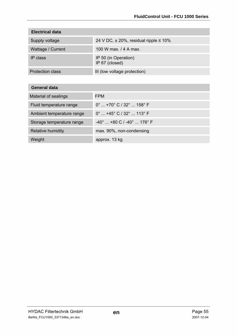
Electrical data
Supply voltage 24 V DC, ± 20%, residual ripple ≤ 10%
Wattage / Current 100 W max. / 4 A max.
IP class IP 50 (in Operation) IP 67 (closed)
Protection class III (low voltage protection)
General data
Material of sealings FPM
Fluid temperature range 0° ... +70° C / 32° ... 158° F
Ambient temperature range 0° ... +45° C / 32° ... 113° F
Storage temperature range -40° ... +80 C / -40° ... 176° F
Relative humidity max. 90%, non-condensing
Weight approx. 13 kg
FluidControl Unit - FCU 1000 Series
HYDAC Filtertechnik GmbH en Page 56BeWa_FCU1000_3371346a_en.doc 2007-12-04
15 ISO 4406 / SAE AS 4059 and NAS 1638 Classes
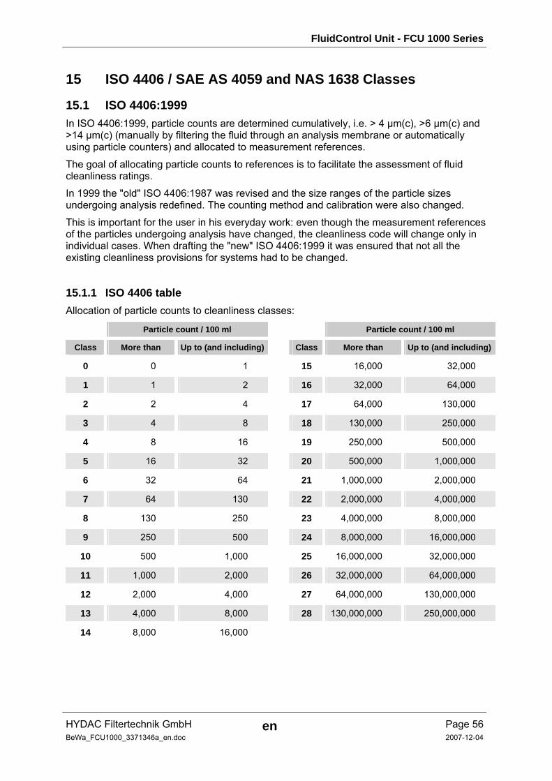
15.1 ISO 4406:1999 In ISO 4406:1999, particle counts are determined cumulatively, i.e. > 4 µm(c), >6 µm(c) and >14 µm(c) (manually by filtering the fluid through an analysis membrane or automatically using particle counters) and allocated to measurement references.
The goal of allocating particle counts to references is to facilitate the assessment of fluid cleanliness ratings.
In 1999 the "old" ISO 4406:1987 was revised and the size ranges of the particle sizes undergoing analysis redefined. The counting method and calibration were also changed.
This is important for the user in his everyday work: even though the measurement references of the particles undergoing analysis have changed, the cleanliness code will change only in individual cases. When drafting the "new" ISO 4406:1999 it was ensured that not all the existing cleanliness provisions for systems had to be changed.
15.1.1 ISO 4406 table Allocation of particle counts to cleanliness classes:
Particle count / 100 ml Particle count / 100 ml
Class More than Up to (and including) Class More than Up to (and including)
0 0 1 15 16,000 32,000
1 1 2 16 32,000 64,000
2 2 4 17 64,000 130,000
3 4 8 18 130,000 250,000
4 8 16 19 250,000 500,000
5 16 32 20 500,000 1,000,000
6 32 64 21 1,000,000 2,000,000
7 64 130 22 2,000,000 4,000,000
8 130 250 23 4,000,000 8,000,000
9 250 500 24 8,000,000 16,000,000
10 500 1,000 25 16,000,000 32,000,000
11 1,000 2,000 26 32,000,000 64,000,000
12 2,000 4,000 27 64,000,000 130,000,000
13 4,000 8,000 28 130,000,000 250,000,000
14 8,000 16,000
FluidControl Unit - FCU 1000 Series
HYDAC Filtertechnik GmbH en Page 57BeWa_FCU1000_3371346a_en.doc 2007-12-04
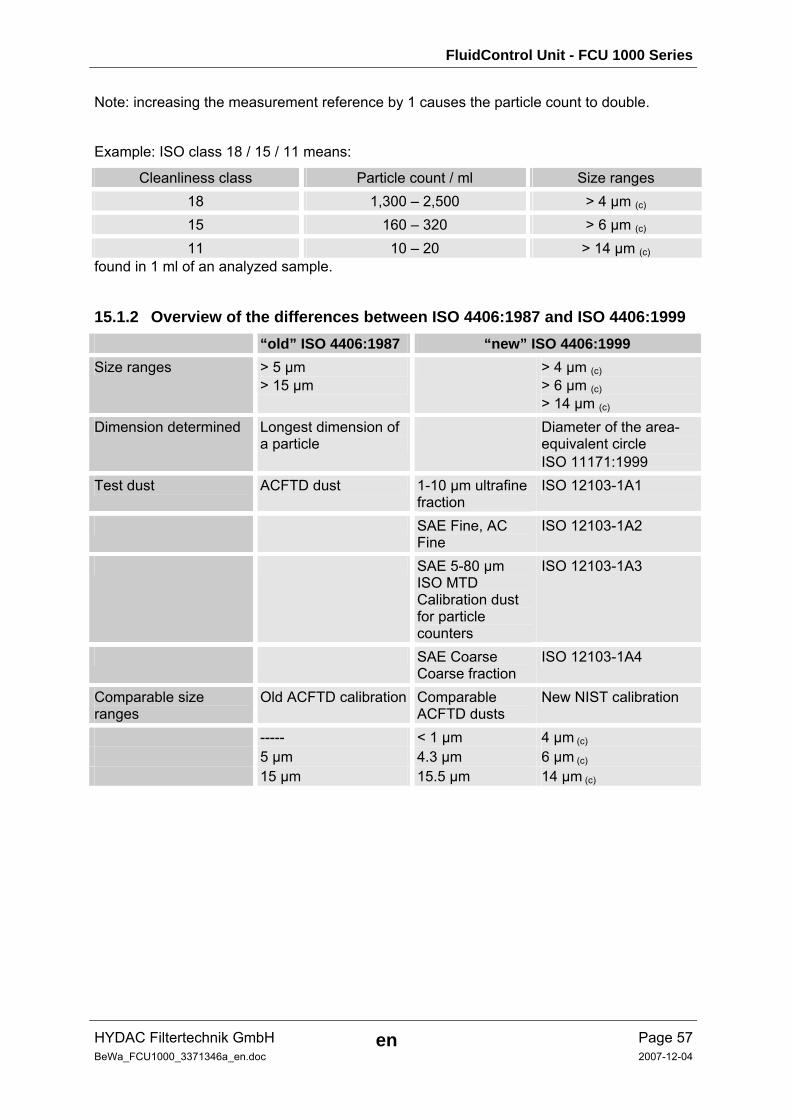
Note: increasing the measurement reference by 1 causes the particle count to double.
Example: ISO class 18 / 15 / 11 means:
Cleanliness class Particle count / ml Size ranges 18 1,300 – 2,500 > 4 µm (c) 15 160 – 320 > 6 µm (c) 11 10 – 20 > 14 µm (c)
found in 1 ml of an analyzed sample.
15.1.2 Overview of the differences between ISO 4406:1987 and ISO 4406:1999 “old” ISO 4406:1987 “new” ISO 4406:1999 Size ranges > 5 µm
> 15 µm > 4 µm (c)
> 6 µm (c) > 14 µm (c)
Dimension determined Longest dimension of a particle
Diameter of the area-equivalent circle ISO 11171:1999
Test dust ACFTD dust 1-10 µm ultrafine fraction
ISO 12103-1A1
SAE Fine, AC Fine
ISO 12103-1A2
SAE 5-80 µm ISO MTD Calibration dust for particle counters
ISO 12103-1A3
SAE Coarse Coarse fraction
ISO 12103-1A4
Comparable size ranges
Old ACFTD calibration Comparable ACFTD dusts
New NIST calibration
----- < 1 µm 4 µm (c) 5 µm 4.3 µm 6 µm (c) 15 µm 15.5 µm 14 µm (c)
FluidControl Unit - FCU 1000 Series
HYDAC Filtertechnik GmbH en Page 58BeWa_FCU1000_3371346a_en.doc 2007-12-04
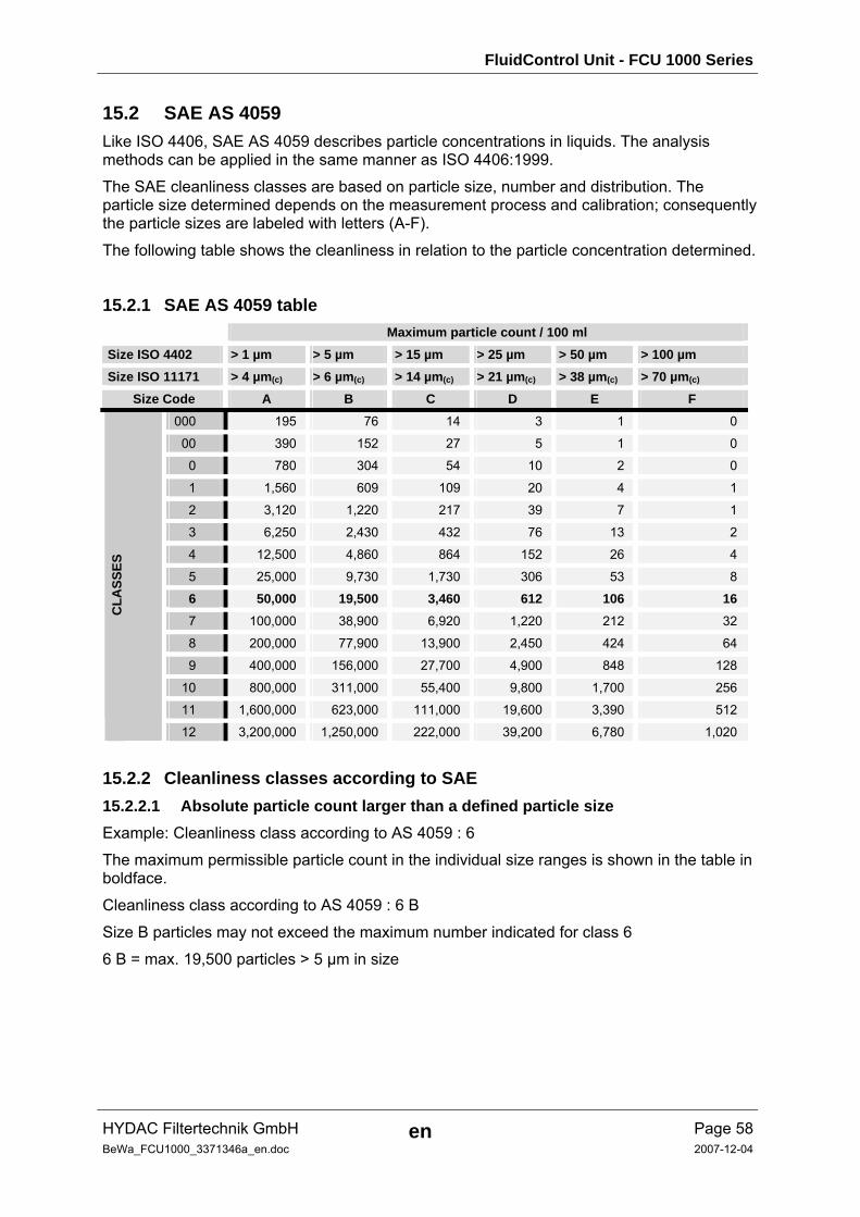
15.2 SAE AS 4059 Like ISO 4406, SAE AS 4059 describes particle concentrations in liquids. The analysis methods can be applied in the same manner as ISO 4406:1999.
The SAE cleanliness classes are based on particle size, number and distribution. The particle size determined depends on the measurement process and calibration; consequently the particle sizes are labeled with letters (A-F).
The following table shows the cleanliness in relation to the particle concentration determined.
15.2.1 SAE AS 4059 table Maximum particle count / 100 ml Size ISO 4402 > 1 µm > 5 µm > 15 µm > 25 µm > 50 µm > 100 µm Size ISO 11171 > 4 µm(c) > 6 µm(c) > 14 µm(c) > 21 µm(c) > 38 µm(c) > 70 µm(c)
Size Code A B C D E F 000 195 76 14 3 1 0
00 390 152 27 5 1 0
0 780 304 54 10 2 0
1 1,560 609 109 20 4 1
2 3,120 1,220 217 39 7 1
3 6,250 2,430 432 76 13 2
4 12,500 4,860 864 152 26 4
5 25,000 9,730 1,730 306 53 8
6 50,000 19,500 3,460 612 106 16 7 100,000 38,900 6,920 1,220 212 32
8 200,000 77,900 13,900 2,450 424 64
9 400,000 156,000 27,700 4,900 848 128
10 800,000 311,000 55,400 9,800 1,700 256
11 1,600,000 623,000 111,000 19,600 3,390 512
CLA
SSES
12 3,200,000 1,250,000 222,000 39,200 6,780 1,020
15.2.2 Cleanliness classes according to SAE 15.2.2.1 Absolute particle count larger than a defined particle size Example: Cleanliness class according to AS 4059 : 6
The maximum permissible particle count in the individual size ranges is shown in the table in boldface.
Cleanliness class according to AS 4059 : 6 B
Size B particles may not exceed the maximum number indicated for class 6
6 B = max. 19,500 particles > 5 µm in size
FluidControl Unit - FCU 1000 Series
HYDAC Filtertechnik GmbH en Page 59BeWa_FCU1000_3371346a_en.doc 2007-12-04
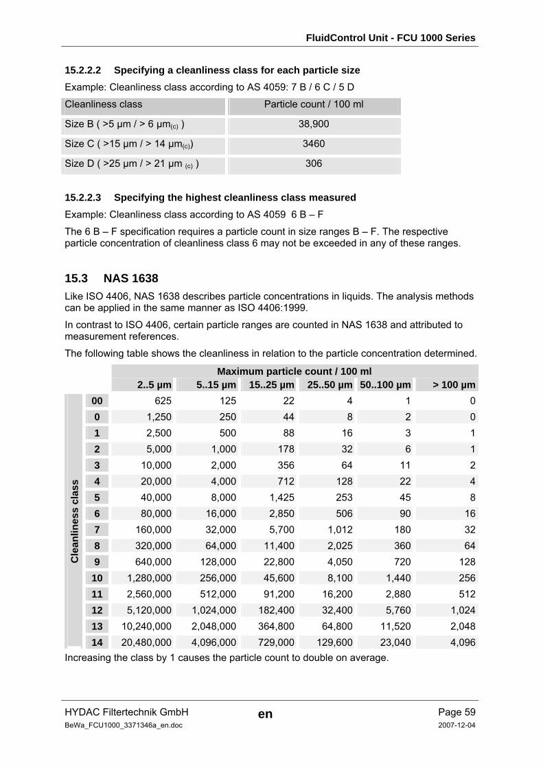
15.2.2.2 Specifying a cleanliness class for each particle size Example: Cleanliness class according to AS 4059: 7 B / 6 C / 5 D
Cleanliness class Particle count / 100 ml
Size B ( >5 µm / > 6 µm(c) ) 38,900
Size C ( >15 µm / > 14 µm(c)) 3460
Size D ( >25 µm / > 21 µm (c) ) 306
15.2.2.3 Specifying the highest cleanliness class measured Example: Cleanliness class according to AS 4059 6 B – F
The 6 B – F specification requires a particle count in size ranges B – F. The respective particle concentration of cleanliness class 6 may not be exceeded in any of these ranges.
15.3 NAS 1638 Like ISO 4406, NAS 1638 describes particle concentrations in liquids. The analysis methods can be applied in the same manner as ISO 4406:1999.
In contrast to ISO 4406, certain particle ranges are counted in NAS 1638 and attributed to measurement references.
The following table shows the cleanliness in relation to the particle concentration determined.
Maximum particle count / 100 ml 2..5 µm 5..15 µm 15..25 µm 25..50 µm 50..100 µm > 100 µm
00 625 125 22 4 1 00 1,250 250 44 8 2 01 2,500 500 88 16 3 12 5,000 1,000 178 32 6 13 10,000 2,000 356 64 11 24 20,000 4,000 712 128 22 45 40,000 8,000 1,425 253 45 86 80,000 16,000 2,850 506 90 167 160,000 32,000 5,700 1,012 180 328 320,000 64,000 11,400 2,025 360 649 640,000 128,000 22,800 4,050 720 128
10 1,280,000 256,000 45,600 8,100 1,440 25611 2,560,000 512,000 91,200 16,200 2,880 51212 5,120,000 1,024,000 182,400 32,400 5,760 1,02413 10,240,000 2,048,000 364,800 64,800 11,520 2,048
Cle
anlin
ess
clas
s
14 20,480,000 4,096,000 729,000 129,600 23,040 4,096Increasing the class by 1 causes the particle count to double on average.
FluidControl Unit - FCU 1000 Series
HYDAC Filtertechnik GmbH en Page 60BeWa_FCU1000_3371346a_en.doc 2007-12-04
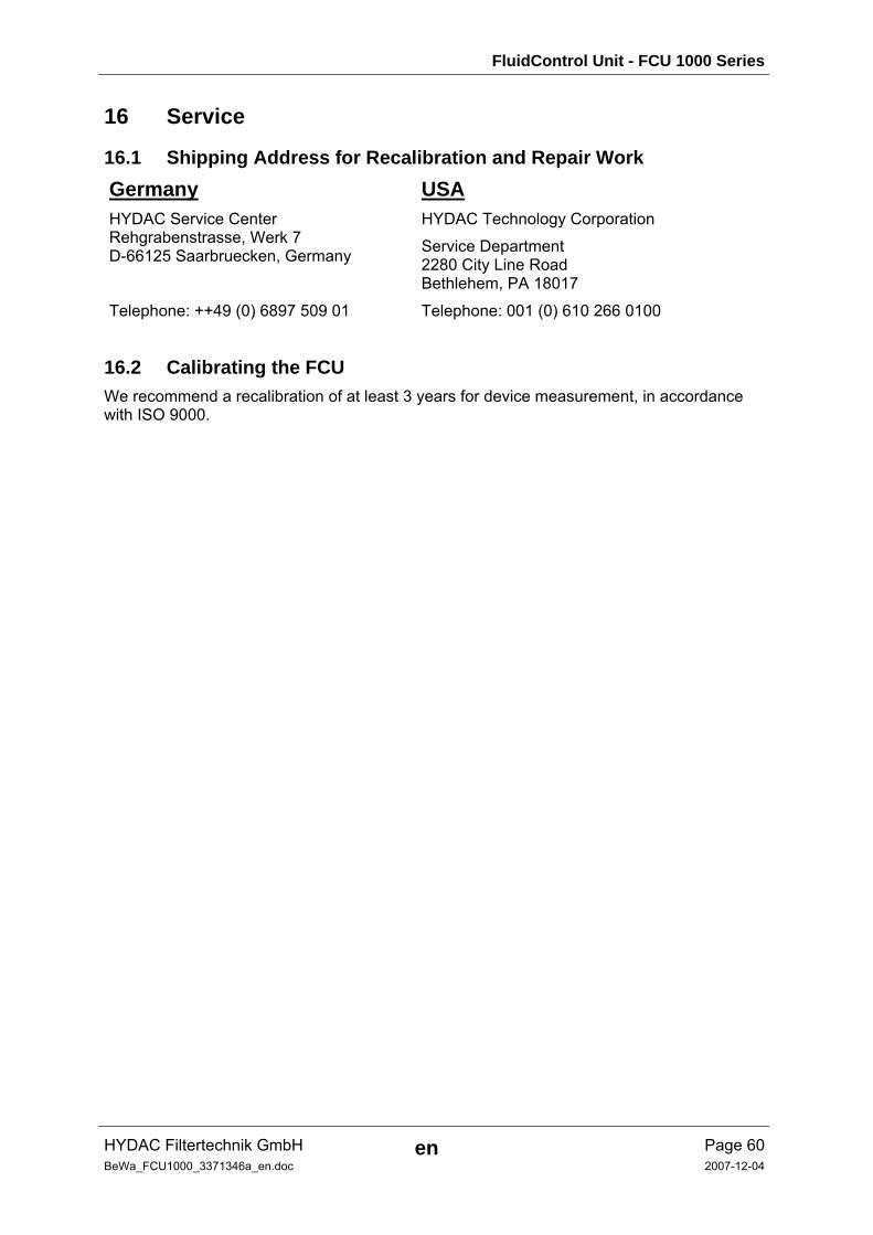
16 Service
16.1 Shipping Address for Recalibration and Repair Work Germany USA HYDAC Service Center Rehgrabenstrasse, Werk 7 D-66125 Saarbruecken, Germany
HYDAC Technology Corporation
Service Department 2280 City Line Road Bethlehem, PA 18017
Telephone: ++49 (0) 6897 509 01 Telephone: 001 (0) 610 266 0100
16.2 Calibrating the FCU We recommend a recalibration of at least 3 years for device measurement, in accordance with ISO 9000.
FluidControl Unit - FCU 1000 Series
HYDAC Filtertechnik GmbH en Page 61BeWa_FCU1000_3371346a_en.doc 2007-12-04
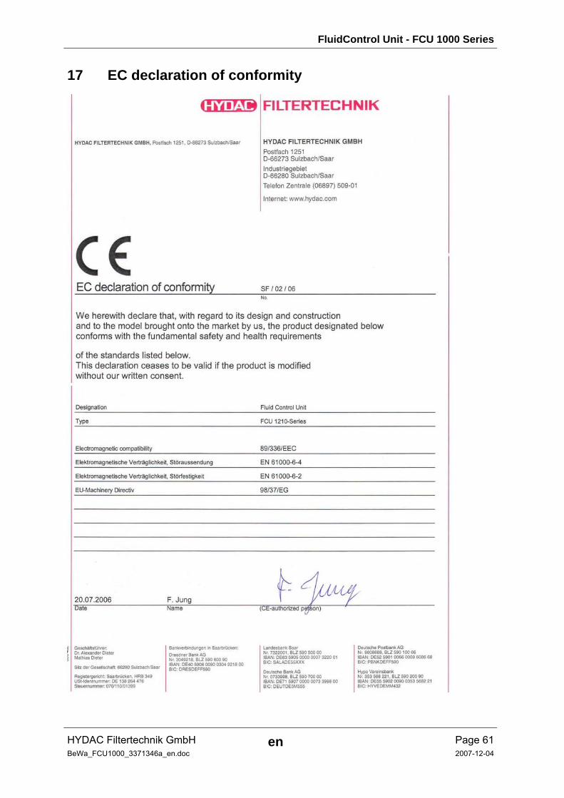
17 EC declaration of conformity

FluidControl Unit - FCU 1000 Series
HYDAC Filtertechnik GmbH en Page 62BeWa_FCU1000_3371346a_en.doc 2007-12-04
Notes
FluidControl Unit - FCU 1000 Series
HYDAC Filtertechnik GmbH en Page 63BeWa_FCU1000_3371346a_en.doc 2007-12-04
Notes
HYDAC Filtertechnik GmbH Bereich Servicetechnik / Service Technology Division Industriegebiet Postfach 1251 66280 Sulzbach/Saar 66273 Sulzbach/Saar Germany Germany Tel: +49 (0) 6897 509 01 Fax: +49 (0) 6897 509 846 (Technical Department) Fax: +49 (0) 6897 509 577 (Sales Department) Internet: www.hydac.com email: [email protected]