fb-3200 - fullbucket.de · fb-3200 manual page 3 introduction the fb-3200 is a software synthesizer...
TRANSCRIPT
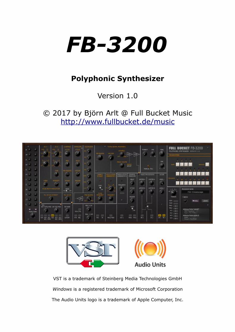
FB-3200Polyphonic Synthesizer
Version 1.0
© 2017 by Björn Arlt @ Full Bucket Musichttp://www.fullbucket.de/music
VST is a trademark of Steinberg Media Technologies GmbH
Windows is a registered trademark of Microsoft Corporation
The Audio Units logo is a trademark of Apple Computer, Inc.
FB-3200 Manual Page 2
Table of Contents
Introduction....................................................3History...........................................................3Digital Transformation......................................4Acknowledgments............................................4Architecture....................................................5Polyphonic Section...........................................6
Signal Generators (SG 1+2).................................6Lowpass Filters (LP)............................................7Envelope Modifiers (EM).......................................7
Monophonic/Paraphonic Section.........................8Equalizer............................................................8Resonators.........................................................8Keyboard Balance...............................................8Amplitude Modulation..........................................8The Remaining Signal Path...................................9
Modulation Generators....................................10MG1 and MG2...................................................10Sample & Hold..................................................10The “MOD” Signal..............................................10General Envelope Generator (GEG)......................11Voltage Processors............................................11Adder..............................................................11External Trigger and Modulation Sources..............12
Programmer..................................................12Tweaks.........................................................13Options Menu................................................13The fb3200.ini Configuration File......................14
MIDI Control Change Messages...........................14MIDI Learn.......................................................14
Modulation and Trigger Sources........................15Parameters...................................................16
Global..............................................................16Signal Generators..............................................16Lowpass Filter...................................................17Envelope Modifier..............................................17Equalizer..........................................................18Total Signal Modifiers.........................................18Modulation Generators 1/2 and Sample & Hold......18General Envelope Generator...............................19Voltage Processors 1 and 2.................................19Adder..............................................................19Temperament (Micro-Tuning)..............................20External Modulation and Trigger Sources..............20Tweaks............................................................20Resonators.......................................................20
Frequently Asked Questions.............................21
FB-3200 Manual Page 3
IntroductionThe FB-3200 is a software synthesizer plug-in for Microsoft Windows (VST) and Apple macOS (VST/AU) simulating the classic KORG PS-3200 polyphonic analog synthesizer from 1978. It is written in native C++ code for high performance even on “lighter” systems. The main features are:
● Close emulation of behavior and all controls of the original hardware● Band-limited oscillators, classic lowpass filters● Equalizer section ● Two Modulation Generators, Sample & Hold● Paraphonic Envelope Generator● Semi-modular● Micro-tuning options● Additional tweaks● Plug-in supports Windows and macOS (32 bit and 64 bit)
HistoryIn 1977, KORG released two new synthesizer, the PS-3100 and the PS-3300, where “PS” is short for Polyphonic Synthesizer. By that time not many polyphonic synthesizers were around, and being even fully polyphonic the PS brothers (in close approximation the PS-3300 consists of three PS-3100) were propelled into the noble company of a Polymoog.
While the PS-3100 is a rather modest instrument, the PS-3300 features no less than 3independent synthesizer blocks (comparable to almost a full PS-3100): Each block has48 voices with 48 filters and 48 envelopes but only 12 oscillators generating the top octave frequencies for the twelve keys C to B. The remaining 36 signals are derived byfrequency division.
One year later came the PS-3200, KORG's first programmable polyphonic synthesizer. Compared to the huge PS-3300, the PS-3200 was reduced to a single synthesizer block again (like the PS-3100). But the “2” in the name can be taken literally since there are now two Signal Generators (2 x 12 oscillators plus frequency dividers). Unfortunately the charismatic Resonator section had been dropped and replaced with a static 7-band equalizer.
However, 40 years ago the most impressive feature was the PS-3200’s program memory: The position of 32 knobs could be stored into 16 different programs! While itwas not possible to memorize the patched cable settings nor the remaining controls, programmability still can be regarded as a major step forward. Note though that it was not possible to edit a recalled program of the PS-3200 (as we know it from almostany other programmable synthesizer); once stored, a program behaved like a read-only preset and could only be completely overridden with the current settings on the panel. Those were the days.

FB-3200 Manual Page 4
Digital TransformationAfter creating the FB-3100 and FB-3300 it was reasonable to finish the 3000 series with a simulation of the PS-3200: The FB-3200.
Aim of the project again was to provide a close simulation of the original hardware. But this time I added some additional features that I think are quite useful and/or thatfolks have repeatedly asked for:
• The FB-3200 reacts to Velocity.
• Channel Aftertouch is available as a new modulation source.
• The filter can be switched from the two-pole Korg 35 to a classic four-pole lowpass ladder type.
• The Resonators section is back.
But as usual, there are still some decisions left that folks maybe do not like:
• The FB-3200 is not stereophonic (although you can pan the Final and Direct outputs in the stereo field).
• The monophonic/paraphonic modulation options of the PS-3200 remain monophonic/paraphonic in the FB-3200.
• The UI is too small and at the same time too big. This is always true.
• The plugs of the FB-3200 do not use virtual patch cords but “patch menus”.
And here are the usual tweaks also not to be found on the original PS series:
• Modulation Generators and Sample & Hold can be synchronized to the host.
• MIDI controllers can be used as sources for virtual voltages and triggers.
• The FB-3200 features a few more modulation sources than the PS-3200.
Acknowledgments First I wanted to thank Cockos and Oli Larkin for developing and maintaining the
WDL(-OL)/IPlug framework, and Laurent Bergman for his French manuals.
A big Thank you! goes to all the people who share their information about the PS synthesizers via the Internet.
Some of the micro-tuning templates are derived from the Microtonal Synthesis website at http://www.microtonal-synthesis.com/.
Furthermore a BIG THANKS to Tim Stinchcombe and Will Pirkle for their in-depth analysis of the K35 filter chip.
Last not least another THANK YOU! to the KVR Audio community and to the KORG engineers.
No, I am not affiliated with KORG in what relation ever except that I always find myself entangled with their instruments.

FB-3200 Manual Page 5
ArchitectureEach of the 64 voices of the FB-3200 features two band-limited Signal Generators (SG 1+2), a Lowpass filter (LP), and an Envelope Modulator (EM). The mix of all voices is then sent into a single (!) Resonators1 and Equalizer section, followed by an Amplitude Modulation section and two Voltage Controlled Amplifiers (VCAs). For modulation purposes the FB-3200 has two Modulation Generators (MG 1+2), a Sample & Hold unit, an additional General Envelope Generator (GEG), two Voltage Processors (VP 1+2), and an Adder module (ADD).
As you can see from the block diagram, there are many signal (solid) and modulation (dashed) paths between the various modules. The configuration is pretty flexible and can be reconfigured by using the plugs. You can see, too, that further processing of the polyphonic signals after the LP section is monophonic (better: paraphonic). For example the modulation of VCA1 does affect the volume of all voices and not that of an individual voice. In the same sense the GEG acts as a paraphonic envelope and notper voice.
1 As stated above, the Resonators have been dropped from the original PS-3200. It doesn’t hurt to add this great feature back to the FB-3200 though.
SG 1+2 LP
EM
RES AM VCA2RES AM VCA1
GEGS/H MG1 MG2 VP2VP1
MG1
VCA EQ
FB-3200 only!
FB-3200 Manual Page 6
Polyphonic Section
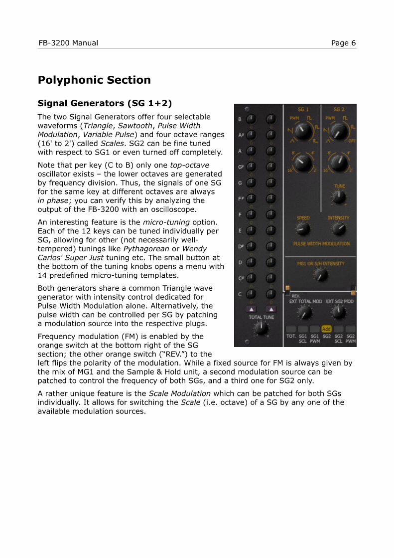
Signal Generators (SG 1+2)
The two Signal Generators offer four selectablewaveforms (Triangle, Sawtooth, Pulse WidthModulation, Variable Pulse) and four octave ranges(16' to 2') called Scales. SG2 can be fine tunedwith respect to SG1 or even turned off completely.
Note that per key (C to B) only one top-octave oscillator exists ‒ the lower octaves are generatedby frequency division. Thus, the signals of one SGfor the same key at different octaves are always in phase; you can verify this by analyzing theoutput of the FB-3200 with an oscilloscope.
An interesting feature is the micro-tuning option.Each of the 12 keys can be tuned individually perSG, allowing for other (not necessarily well-tempered) tunings like Pythagorean or WendyCarlos' Super Just tuning etc. The small button atthe bottom of the tuning knobs opens a menu with14 predefined micro-tuning templates.
Both generators share a common Triangle wavegenerator with intensity control dedicated forPulse Width Modulation alone. Alternatively, thepulse width can be controlled per SG by patchinga modulation source into the respective plugs.
Frequency modulation (FM) is enabled by theorange switch at the bottom right of the SGsection; the other orange switch (“REV.”) to theleft flips the polarity of the modulation. While a fixed source for FM is always given by the mix of MG1 and the Sample & Hold unit, a second modulation source can be patched to control the frequency of both SGs, and a third one for SG2 only.
A rather unique feature is the Scale Modulation which can be patched for both SGs individually. It allows for switching the Scale (i.e. octave) of a SG by any one of the available modulation sources.

FB-3200 Manual Page 7
Lowpass Filters (LP)
The outputs of the Signal Generators are fed into a lowpass filtersection with adjustable resonance (Peak). As opposed to theoriginal hardware, the mode can be switched from an emulationof the famous KORG K-35 two-pole to a classic four-pole ladderfilter.
Cutoff frequency modulation comes in various ways: First of allthe cutoff frequency can be controlled by the note played (KBDBalance) both in positive and negative direction (here negativemeans that the cutoff frequency will be lower for higher notes).
The next knob, Expand, controls the influence of the EnvelopeModifier (see next section) on the cutoff frequency while theremaining options for frequency modulation resemble those ofthe Signal Generators: Activated by the orange switch, the filtercan be modulated by the (fixed) MG or Sample & Hold signal anda second source patched into the plug at the bottom.
Envelope Modifiers (EM)
The envelopes are of the standard ADSR type – nothing specialhere. The attack time can be externally controlled by amodulation source plugged into ATK while a trigger signal from asource plugged into REL will put the EM into the release phase(i.e. stop the envelope)..

FB-3200 Manual Page 8
Monophonic/Paraphonic Section
Equalizer
The individual voice signals are mixed into a singlemonophonic signal (the Direct signal) and sent into the Equalizer section. This is basically a parallel arrangementof seven peak filters with fixed Q and individuallyadjustable gain.
Resonators
The original Resonators section of the PS-3100/3300brothers has become pretty famous and is one of the keyfeatures giving them their “signature sound”. While it wasreplaced in the PS-3200 by the static Equalizer, the FB-3200 brings it back to life – you just have to click thesmall switch at the bottom right of the Equalizer section.
The resonators are a parallel arrangement of threebandpass filters with high Q and individually adjustablecenter frequencies. The “INTENSITY” control determinesthe mix between original and effect signal. The resonatorfrequencies can be modulated by a modulation source that has to be selected via the plug at the bottom. The intensity of the modulation can be adjusted continuously using the “EXT MOD” knob.
Keyboard Balance
Following the Equalizer/Resonators, the signal is treated by a pretty uniquefeature: The Keyboard Balance which adjusts the volume of notes asplayed on the keyboard. With this control you can attenuate notes on thelower end or vice versa.
Amplitude Modulation
The signal now runs through an Amplitude Modulator which multiplies itwith the signal of MG1. Here, the “AMP MOD” knob sets the intensity andcharacter of the effect as follows:
• The range from 0% to 50% (i.e. from the very left to the center ofthe knob range) will result in a Cross Modulation effect. This meansthat the amplitude of the signal is modulated from -∞ dB to amaximum of 0dB.
• The range from 50% to 100% (i.e. from the center to the very rightof the knob range) will result in a Ring Modulation effect meaningthat negative values of the MG1 signal will (apart from attenuation)cause the modulated signal to be inverted. This makes perfect sense if you think of Ring modulation as a multiplication.

FB-3200 Manual Page 9
The interesting thing is that MG1 is able to generate signals in the kilohertz range which allows for drastic sound effects. But even in the low range a Ring Modulation with a sawtooth wave can result in unusual gate effects.
The Remaining Signal Path
After Amplitude Modulation the signal passes through an Ensemble effect as known from classic string synthesizers of the 70's. The intensity of the effect can be controlled from “Off” to “Max”. Compared to the PS-3200, the FB-3200 Ensemble effect does produce much less noise!
Next to follow are two individual VCAs (Voltage Controlled Amplifiers) forfurther amplitude modulation. Thepurpose of these amplifiers is thedynamic control of the loudnesscontour by a variable modulationsource and Voltage Processor 1 (canbe enabled using the orange switch).
Finally, the Final knob controls theoutput volume of the full signal pathwhile the Direct knob controls the volume of an additional outlet of the polyphonic signal i.e. a mix of all voices after the lowpass filters but before the Equalizer/Resonators section. This is because the original PS-3200 offers two mono outputs, namely the Final and the Direct signals. On the FB-3200 you can pan both signals individually (see Tweaks section) which gives a bit more flexibility.

FB-3200 Manual Page 10
Modulation Generators
MG1 and MG2
The FB-3200 has two Modulation Generators (LFOs). The secondone, MG2, only offers a triangle wave while the first one, MG1,is much more flexible and can produce a triangle, a falling orrising sawtooth, and a square wave as well as (prettyuncommon!) Pink Noise and White Noise. Except for the noisewaves (which have a continuous frequency range) the frequencyof MG1 can be set up to about 1.6kHz ‒ again a very uncommonbut nice feature!
Both MGs can be synchronized to the host tempo. Furthermore,by patching an appropriate source one can modulate thefrequency of MG1.
Sample & Hold
The Sample & Hold (S&H) unit samples whatever signal is sentinto the input plug IN. The sample rate can be synchronized tothe host tempo. Alternatively, it will sample the input on anytrigger impulse at the plug TRG.
The “SYNC” switch (called “SYNCHRO” on the PS-3200) is bit curious.KORG’s original documentation states that “when the sampled frequencyis near the clock frequency multiplied by an integer, the clock issynchronized”. Well, better check it out by yourself. Fact is that aregular/periodic input signal can produce some regular, repetitive outputwhile noise will create random patterns. In any casethe SYNC function is disabled when the S&H clock issynchronized to the host tempo.
The “MOD” Signal
The MOD signal is simply a balanced mix between theSample & Hold and the MG1 signal. Its amplitude canbe controlled by a modulation source patched to theplug VCA CTRL. This makes it easy to create effects like Delayed Vibrato.
FB-3200 Manual Page 11
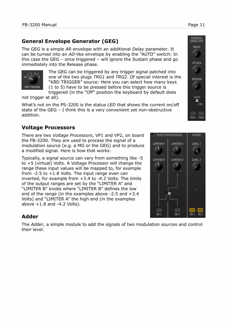
General Envelope Generator (GEG)
The GEG is a simple AR envelope with an additional Delay parameter. Itcan be turned into an AD-like envelope by enabling the “AUTO” switch: Inthis case the GEG ‒ once triggered ‒ will ignore the Sustain phase and goimmediately into the Release phase.
The GEG can be triggered by any trigger signal patched intoone of the two plugs TRG1 and TRG2. Of special interest is the“KBD TRIGGER” source: Here you can select how many keys(1 to 5) have to be pressed before this trigger source istriggered (in the “Off” position the keyboard by default does
not trigger at all).
What’s not on the PS-3200 is the status LED that shows the current on/offstate of the GEG ‒ I think this is a very convenient yet non-obstructiveaddition.
Voltage Processors
There are two Voltage Processors, VP1 and VP2, on boardthe FB-3200. They are used to process the signal of amodulation source (e.g. a MG or the GEG) and to producea modified signal. Here is how that works:
Typically, a signal source can vary from something like -5to +5 (virtual) Volts. A Voltage Processor will change therange these input values will be mapped to, for examplefrom -2.5 to +1.8 Volts. The input range even caninverted, for example from +3.4 to -4.2 Volts. The limitsof the output ranges are set by the “LIMITER A” and“LIMITER B” knobs where “LIMITER B” defines the lowend of the range (in the examples above -2.5 and +3.4Volts) and “LIMITER A” the high end (in the examplesabove +1.8 and -4.2 Volts).
Adder
The Adder, a simple module to add the signals of two modulation sources and control their level.
FB-3200 Manual Page 12
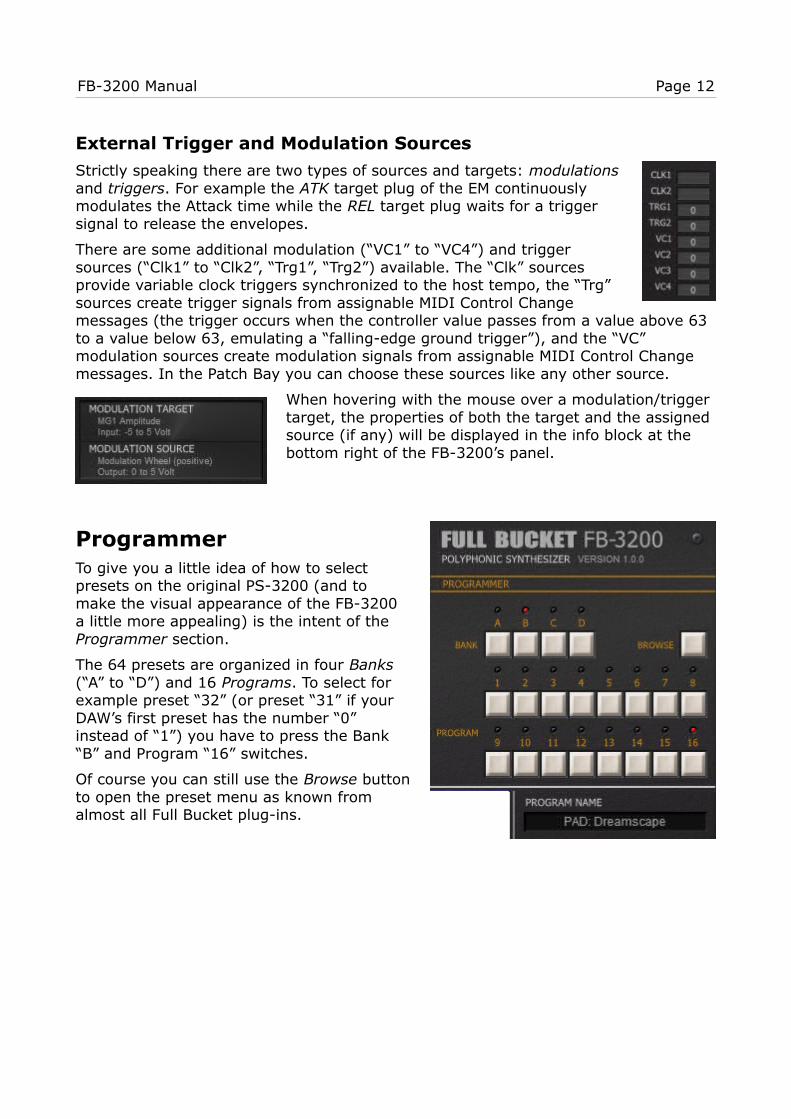
External Trigger and Modulation Sources
Strictly speaking there are two types of sources and targets: modulationsand triggers. For example the ATK target plug of the EM continuouslymodulates the Attack time while the REL target plug waits for a triggersignal to release the envelopes.
There are some additional modulation (“VC1” to “VC4”) and triggersources (“Clk1” to “Clk2”, “Trg1”, “Trg2”) available. The “Clk” sourcesprovide variable clock triggers synchronized to the host tempo, the “Trg”sources create trigger signals from assignable MIDI Control Changemessages (the trigger occurs when the controller value passes from a value above 63 to a value below 63, emulating a “falling-edge ground trigger”), and the “VC” modulation sources create modulation signals from assignable MIDI Control Change messages. In the Patch Bay you can choose these sources like any other source.
When hovering with the mouse over a modulation/trigger target, the properties of both the target and the assigned source (if any) will be displayed in the info block at the bottom right of the FB-3200’s panel.
ProgrammerTo give you a little idea of how to selectpresets on the original PS-3200 (and tomake the visual appearance of the FB-3200a little more appealing) is the intent of the Programmer section.
The 64 presets are organized in four Banks(“A” to “D”) and 16 Programs. To select forexample preset “32” (or preset “31” if yourDAW’s first preset has the number “0”instead of “1”) you have to press the Bank“B” and Program “16” switches.
Of course you can still use the Browse buttonto open the preset menu as known fromalmost all Full Bucket plug-ins.
FB-3200 Manual Page 13
TweaksIn the section Digital Transformation above it has already beenmentioned that the FB-3200 contains some additional features (tweaks)that the original PS-3200 hardware synthesizer does not have.
• Additional modulation sources and S&H input sources
• Additional trigger sources “Clk1”, “Clk2”, “Trg1”, “Trg2”
• Panorama control for Final and Direct output
• Resonators section
• Controls for Velocity sensitivity of lowpass filters and VCA
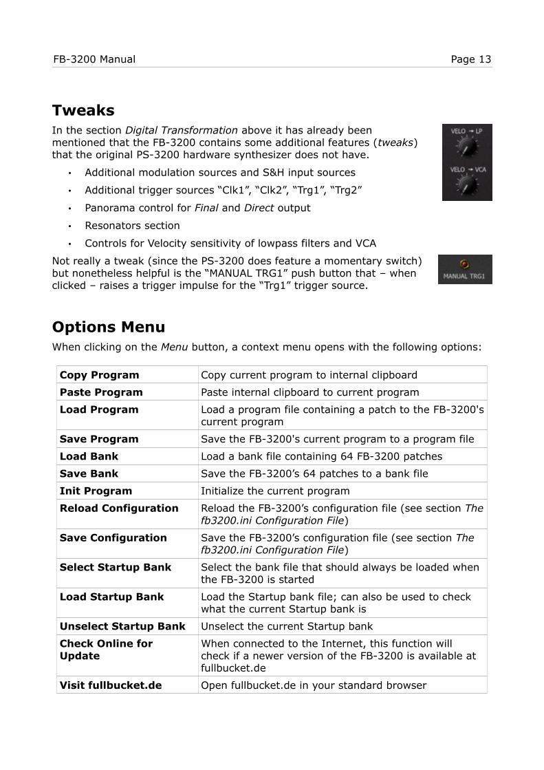
Not really a tweak (since the PS-3200 does feature a momentary switch)but nonetheless helpful is the “MANUAL TRG1” push button that ‒ whenclicked ‒ raises a trigger impulse for the “Trg1” trigger source.
Options MenuWhen clicking on the Menu button, a context menu opens with the following options:
Copy Program Copy current program to internal clipboard
Paste Program Paste internal clipboard to current program
Load Program Load a program file containing a patch to the FB-3200'scurrent program
Save Program Save the FB-3200's current program to a program file
Load Bank Load a bank file containing 64 FB-3200 patches
Save Bank Save the FB-3200’s 64 patches to a bank file
Init Program Initialize the current program
Reload Configuration Reload the FB-3200’s configuration file (see section Thefb3200.ini Configuration File)
Save Configuration Save the FB-3200’s configuration file (see section The fb3200.ini Configuration File)
Select Startup Bank Select the bank file that should always be loaded when the FB-3200 is started
Load Startup Bank Load the Startup bank file; can also be used to check what the current Startup bank is
Unselect Startup Bank Unselect the current Startup bank
Check Online for Update
When connected to the Internet, this function will check if a newer version of the FB-3200 is available at fullbucket.de
Visit fullbucket.de Open fullbucket.de in your standard browser

FB-3200 Manual Page 14
The fb3200.ini Configuration FileThe FB-3200 is able to read some settings from a configuration file (fb3200.ini) located in the same directory as the FB-3200 VST DLL (fb3200.dll or fb320064.dll)or Mac VST/AU (FB3200.component or FB3200.vst) itself. After you have edited this INI file in a text editor, you have to reload it using the Reload Configuration command from the File menu (see section The fb3200.ini Configuration File).
MIDI Control Change Messages
All parameters of the FB-3200 can be controlled by MIDI controllers, or more precise: Each MIDI controller (except Modulation Wheel and Sustain Pedal) can control one of FB-3200’s parameters. The mapping is defined in the fb3200.ini for example like this:
[MIDI Control]CC7 = 0 # Final VolumeCC70 = 17 # LP CutoffCC71 = 18 # LP Peak...
The syntax is straight forward:
CC<controller number> = <parameter ID>
Given the above example, controller 7 directly controls the overall Volume parameter, controller 74 the VCF Cutoff etc. As you can see, comments are introduced by the Pound sign (#); they are here just for description purposes and completely optional.
MIDI Learn
The easiest way to assign MIDI controllers to FB-3200 parameters is to use the MIDI Learn function. To activate MIDI Learn, click on the respective button and wiggle both the MIDI controller and the FB-3200’s parameter that you want to link. If you want to unlearn the assignment, right-click the MIDI Learn button (the label now reads “UNLEARN”) and activate it. Now wiggle the MIDI controller or the parameter that youwant to unlearn.
FB-3200 Manual Page 15
Modulation and Trigger Sources
Modulation Sources
Name Voltage Group Description
off 0 ‒ off / default
+5V +5 ‒ maximum value
-5V -5 ‒ minimum value
GE1 0 to 5 Intern GEG inverted output
GE2 -5 to 0 Intern GEG normal output
GE3 0 to 5 Intern GEG normal output
Mod -5 to 5 Intern Mixed S&H / MG1 output
MG1 or MG2 -5 to 5 Intern MG1 or MG2 output
S&H2 -5 to 5 Intern S&H output
VP1 or VP2 -5 to 5 Intern VP1 or VP2 output
Add -5 to 5 Intern Adder output
Key -5 to 5 Extern last pressed key
Aft 0 to 5 Extern Channel Aftertouch/Pressure
PB -5 to 5 Extern Pitch Bend
PB+ 0 to 5 Extern Pitch Bend positive
MW -5 to 5 Extern Mod Wheel
MW+ 0 to 5 Extern Mod Wheel positive
VC1 to VC4 -5 to 5 MIDI assignable MIDI CC
Trigger Sources
Name Group Description
off ‒ off / default
Kbd Intern Keyboard Trigger
Sng Intern Keyboard Single Trigger
Mlt Intern Keyboard Multiple Trigger
MG1 or MG2 Intern MG1 or MG2 clock
S&H Intern S&H clock
Clk1 or Clk2 Extern external clock
Trg1 or Trg2 Extern MIDI CC trigger
2 For the S&H input, this source is replaced by RND, a random signal (white noise).
FB-3200 Manual Page 16
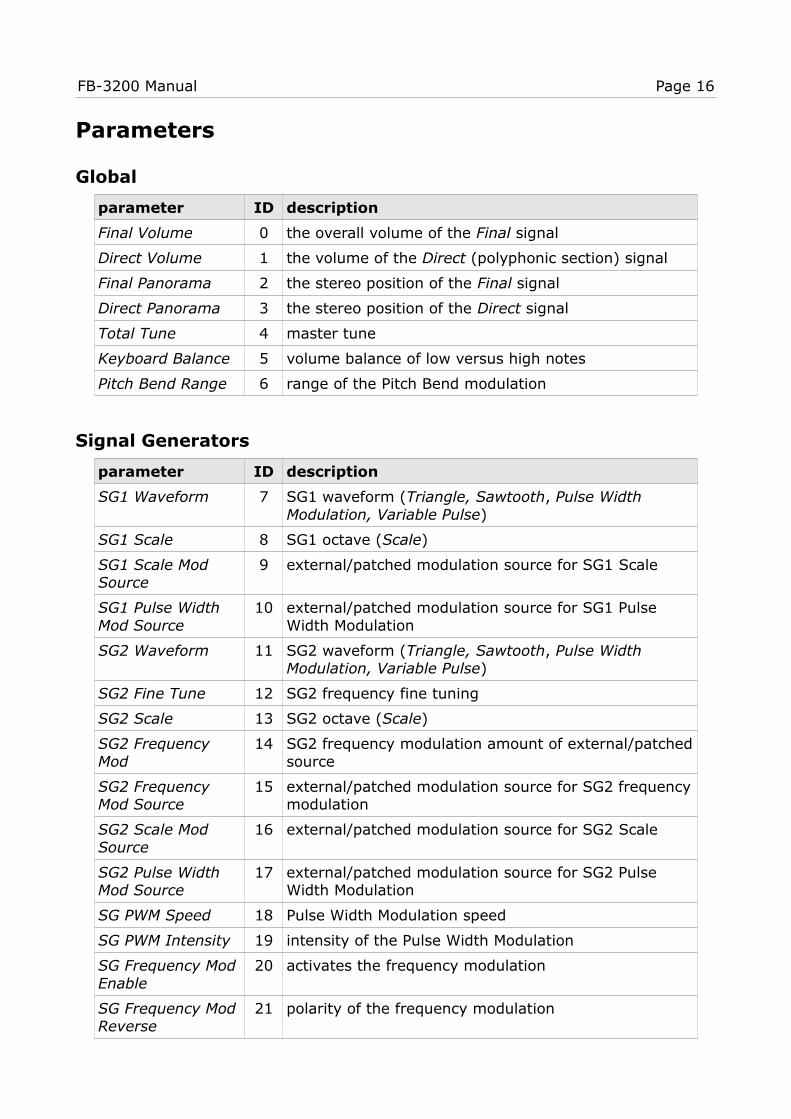
Parameters
Global
parameter ID description
Final Volume 0 the overall volume of the Final signal
Direct Volume 1 the volume of the Direct (polyphonic section) signal
Final Panorama 2 the stereo position of the Final signal
Direct Panorama 3 the stereo position of the Direct signal
Total Tune 4 master tune
Keyboard Balance 5 volume balance of low versus high notes
Pitch Bend Range 6 range of the Pitch Bend modulation
Signal Generators
parameter ID description
SG1 Waveform 7 SG1 waveform (Triangle, Sawtooth, Pulse Width Modulation, Variable Pulse)
SG1 Scale 8 SG1 octave (Scale)
SG1 Scale Mod Source
9 external/patched modulation source for SG1 Scale
SG1 Pulse Width Mod Source
10 external/patched modulation source for SG1 Pulse Width Modulation
SG2 Waveform 11 SG2 waveform (Triangle, Sawtooth, Pulse Width Modulation, Variable Pulse)
SG2 Fine Tune 12 SG2 frequency fine tuning
SG2 Scale 13 SG2 octave (Scale)
SG2 Frequency Mod
14 SG2 frequency modulation amount of external/patchedsource
SG2 Frequency Mod Source
15 external/patched modulation source for SG2 frequencymodulation
SG2 Scale Mod Source
16 external/patched modulation source for SG2 Scale
SG2 Pulse Width Mod Source
17 external/patched modulation source for SG2 Pulse Width Modulation
SG PWM Speed 18 Pulse Width Modulation speed
SG PWM Intensity 19 intensity of the Pulse Width Modulation
SG Frequency ModEnable
20 activates the frequency modulation
SG Frequency ModReverse
21 polarity of the frequency modulation

FB-3200 Manual Page 17
parameter ID description
SG Frequency Modby MOD Signal
22 frequency modulation amount of mixed S&H / MG1 signal
SG Total Frequency Mod
23 total frequency modulation amount of external/patched source
SG Total Freq. ModSource
24 external/patched modulation source for total frequency modulation
Lowpass Filter
parameter ID description
LP Cutoff Frequency
25 cutoff frequency
LP Peak 26 peak (resonance)
LP Balance 27 keyboard balance (tracking)
LP Expand 28 intensity of modulation by Envelope Modifier
LP Frequency Mod Enable
29 activates the cutoff frequency modulation
LP Frequency Mod by MOD Signal
30 cutoff frequency modulation amount of mixed S&H / MG1 signal
LP Frequency Mod 31 cutoff frequency modulation amount of external/patched source
LP Frequency Mod Source
32 external/patched modulation source for cutoff frequency modulation
Envelope Modifier
parameter ID description
EM Attack 33 Attack time
EM Decay 34 Decay time
EM Sustain 35 Sustain level
EM Release 36 Release time
EM Attack Time Mod Source
37 external/patched modulation source for Attack time
EM Release TriggerSource
38 external/patched trigger source for Release phase

FB-3200 Manual Page 18
Equalizer
parameter ID description
8 kHz Gain 39 gain of the 8 kHz band
4 kHz Gain 40 gain of the 4 kHz band
2 kHz Gain 41 gain of the 2 kHz band
1 kHz Gain 42 gain of the 1 kHz band
500 Hz Gain 43 gain of the 500 Hz band
250 Hz Gain 44 gain of the 250 Hz band
125 Hz Gain 45 gain of the 125 Hz band
Total Signal Modifiers
parameter ID description
Amplitude Mod Intensity
46 intensity of the Amplitude Modulation
Ensemble 47 intensity of the Ensemble effect
Preset Volume 48 initial volume of VCA1
VCA1 Amplitude Mod Source
49 external/patched modulation source for VCA1
VCA2 Mod by VP1 50 activates the modulation of VCA2 by VP1
Modulation Generators 1/2 and Sample & Hold
parameter ID description
S&H / MG1 Balance
51 mix between S&H and MG1 for MOD signal
MOD Signal VCA Control
52 external/patched source for amplitude modulation of the MOD signal
S&H Clock Frequency
53 sample clock rate
S&H Synchro 54 Activates the Synchro function
S&H Sync to Host 55 sync to host tempo rate
S&H Trigger Source
56 external/patched trigger source
S&H Input Source 57 external/patched sample input source
MG1 Waveform 58 Waveform (Triangle, Falling Sawtooth, Rising Sawtooth, Square, Pink Noise, White Noise)
MG1 Frequency 59 frequency of MG1
MG1 Sync to Host 60 sync to host tempo rate
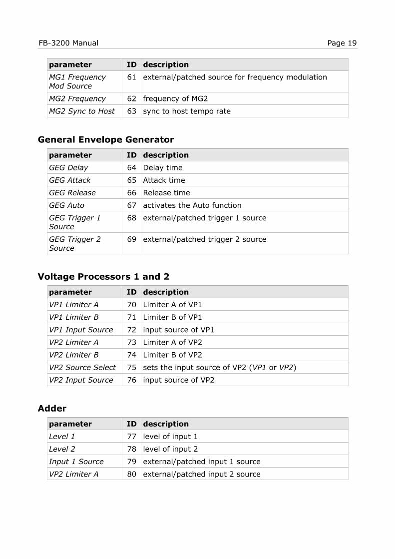
FB-3200 Manual Page 19
parameter ID description
MG1 Frequency Mod Source
61 external/patched source for frequency modulation
MG2 Frequency 62 frequency of MG2
MG2 Sync to Host 63 sync to host tempo rate
General Envelope Generator
parameter ID description
GEG Delay 64 Delay time
GEG Attack 65 Attack time
GEG Release 66 Release time
GEG Auto 67 activates the Auto function
GEG Trigger 1 Source
68 external/patched trigger 1 source
GEG Trigger 2 Source
69 external/patched trigger 2 source
Voltage Processors 1 and 2
parameter ID description
VP1 Limiter A 70 Limiter A of VP1
VP1 Limiter B 71 Limiter B of VP1
VP1 Input Source 72 input source of VP1
VP2 Limiter A 73 Limiter A of VP2
VP2 Limiter B 74 Limiter B of VP2
VP2 Source Select 75 sets the input source of VP2 (VP1 or VP2)
VP2 Input Source 76 input source of VP2
Adder
parameter ID description
Level 1 77 level of input 1
Level 2 78 level of input 2
Input 1 Source 79 external/patched input 1 source
VP2 Limiter A 80 external/patched input 2 source

FB-3200 Manual Page 20
Temperament (Micro-Tuning)
parameter ID description
SG1 Tune C to B 81 ‒ 92 individual tuning for SG1, keys C to B
SG2 Tune C to B 93 ‒ 104 individual tuning for SG2, keys C to B
External Modulation and Trigger Sources
parameter ID description
Clock1 Source 105 sync to host rate for Clk1
Clock2 Source 106 sync to host rate for Clk2
Trigger1 Source 107 MIDI CC assignment for Trg1
Trigger2 Source 108 MIDI CC assignment for Trg2
VC1 Source 109 MIDI CC assignment for VC1
VC2 Source 110 MIDI CC assignment for VC2
VC3 Source 111 MIDI CC assignment for VC3
VC4 Source 112 MIDI CC assignment for VC4
Tweaks
parameter ID description
KBD Trigger 113 number of keys to be pressed for KBD triggering
Velocity to LP 114 intensity of Velocity to filter cutoff
Velocity to VCA 115 intensity of Velocity to volume
Filter Mode 116 2-pole Korg 35 or 4-pole ladder filter
Resonators
parameter ID description
EQ or Resonator 117 show Equalizer or Resonator section
Resonators Intensity
118 mix between original and Resonators effect signal
Resonator 1 Freq. 119 peak frequency of first resonator
Resonator 2 Freq. 120 peak frequency of second resonator
Resonator 3 Freq. 121 peak frequency of third resonator
Resonators Freq. Mod Intensity
122 amount of Peak frequency modulation by external/patched modulation source
Resonator Freq. Mod Source
123 external/patched modulation source for Peak frequency modulation
FB-3200 Manual Page 21
Frequently Asked QuestionsBefore you read on here, please make sure that you also have read my statements regarding the FB-3200's capabilities and limitations at the beginning of this manual (see section Digital Transformation).
How do I install the FB-3200 (Windows 32 bit version)?Just copy the files fb3200.dll and fb3200.ini from the ZIP archive you have downloaded to your system's or favorite DAW's VST plug-in folder. Your DAW should automatically register the FB-3200 VST plug-in the next time you start it.
How do I install the FB-3200 (Windows 64 bit version)?Just copy the file fb320064.dll and fb3200.ini from the ZIP archive you have downloaded to your system's or favorite DAW's VST plug-in folder. Your DAW should automatically register the FB-3200 VST plug-in the next time you start it.
Note: You may have to remove any existing (32 bit) fb3200.dll from your VST plug-in folder or else your DAW may screw the versions up...
How do I install the FB-3200 (Mac VST universal 32/64 bit)?Just copy the package FB3200.vst and the file fb3200.ini from the ZIP archive you have downloaded to your standard macOS VST plug-in folder (typically /Library/Audio/Plug-Ins/VST). Your DAW should automatically register the FB-3200 VST plug-in the next time you start it.
How do I install the FB-3200 (Mac AU universal 32/64 bit)?Just copy the package FB3200.component and the file fb3200.ini from the ZIP archive you have downloaded to your standard macOS AU plug-in folder (typically /Library/Audio/Plug-Ins/Components). Your DAW should automatically register theFB-3200 AU plug-in the next time you start it.
What is the plug-in ID of the FB-3200?The ID is FB32.
Will you support the FB-3200?Yes. If you have problems, found a bug, or have some suggestions about the FB-3200please send me a mail: [email protected] .
How do I know if a new version of the FB-3200 is available?When connected to the Internet, open the Options menu (see section Options Menu) by clicking the disk icon and select the entry “Check Online for Updates”. If a new version of the FB-3200 is available on fullbucket.de the respective information will be shown in a message box.
Does the PS-3200 have a status LED for the GEG?Nope, I added that to the FB-3200 for convenience.
FB-3200 Manual Page 22
Why do some controls have orange and others white labels?Only 32 controls of the original PS-3200 could be memorize – these were color-coded with orange labels. I transferred this funny scheme to the FB-3200 but it has no deeper meaning there.
Why are the SG Waveform and Scale values set by knobs and not by switches?Again this has to do with the original hardware. All programmable parameters of the PS-3200 were sampled and stored as “continuous” values. When recalled, a parameter value was transformed to a control voltage – the Korg engineers just did not make a distinction between continuous parameters (knobs) and discrete parameters (switches)!
Nice side effects of this concept is that the Signal Generators’ pulse width can be set continously and the Scales controlled by modulation sources.