fast transient stability evaluation by estimation of...
TRANSCRIPT
http://repository.osakafu-u.ac.jp/dspace/
TitleFast Transient Stability Evaluation by Estimation of Electrical Power Out
put
Author(s) Ishigame, Atsushi; Taniguchi, Tsuneo
Editor(s)
CitationBulletin of University of Osaka Prefecture. Series A, Engineering and nat
ural sciences. 1989, 37(2), p.87-97
Issue Date 1989-03-31
URL http://hdl.handle.net/10466/8467
Rights
87
Fast Transient StabMty Evaluation by Estimation
of Mectrieal Power Output
Atsushi ISHIGAME" and Tst;rieo TANIGUCHI**
(Received November 15, 1988)
fhis paper describes a new approach fbr fast evaluation of power system tran:
sient stabdity, taking.into account the volSage dependence of system logd. [he
method is based on the. direct method using energy function. In the mpthoa ・we pr"pose tb calculate the' potentia1 enetgy by polyrioniial expression of ele6uical power''
geUntgrUat{orfsOrsytshteemrff.fll,:3tiOn Of fast eValUatiOn・ The 'method 'is applied to a3 and ag
IThe time required fbr calculation of the proposed method is considerably reducedthan that of the usual direCt method, and' in rrtost cases, the accurticy Qf evaluation is
'also satisfactory. ・' '
1. Introduction
It is a very important problem to construct the reliable power system that prevents
interruption of power supply which is catised by large disturbances. One of the impor-
tant items which should be investigated at this juncture is transient stability, and fast
analysing method for transient stabMty is indispensable for its on-lme evaluation.
Recently, the voltage dependence of system load rnarkedly affects the (lynamic
behavior of a power system. However, on-line evaluation for power system transient
stability with consideration of load characteristics may not be realized, because much
computing time is required, even if the usual direct method is used. ,
in this paper, a new approach is presented, which is based on the direct method
using energy function. In the method, it is proposed to calculate the potential energy by
polynomial expression of electrical power ourtppt, taking into account the valtage
dependence ofsystemload. '' '' / The above method is applied to a 3 machine 9 buses systdrni) and ito a 9 machine
25 buses system2) as numerical examples, and the time for'required calculation of the
proposed method is compared with that of the usual direct method.
2. VbltageDependenceofCompositeLoad
For several years, much effbrt has been devoted to the modeling ofload 6haracter-
istic and some load models have been proposed・fbr simulation studies. Among these
models, a V"-type model is the most fundamental. In this pape.r, the following d,y,namic lg. a.d I,p. ode13),.,is employed.
tt .,, , ,, t.. ,. ,/' t./ ,.1 '4 .t.t . t- tt *
**
Graduate Stu'derit, Department of Elecuical Engineering, Coliege of Engineering.
Department of Electripal E#gineering, College Qf Engipeeringt
'
88 Atsushi ISHIGAME and Tsuneo TANIGUCHI
p(k) = po I (EE(,k))"P + Ap i.Zki
e(k) = k, + (e, - ko)Eo"q ( C
(E・(i)-E(i-i)N
L E<i-i) Je
(E.U,'YP( EU) - Eij- 1)
E(k)
Eo
gy(kz)At,}
J
)nq+Aq
E9-i)
,g,(EEU,)
)e- kT-p "' 1 (1)
)nq.
(2)
where
Po, eo, Eo : mitial values of active power, reactive power and load voltage, respectively,
P(k), e(kl, E(k): values at tk = (k - 1)・At of active power, reactive power and load
voltage, respectively,
np, nq: load parameters of active and reactive pbwer respectively,
71p, 71i : time constants of active and reactive power respectively,
At: time interval.
Specially, this model is static load model atAp =Aq = O, and
np = nq = 2 : constant-impedance load,
np =nq = 1 : constant-currentload,
' np = nq = O: constant-power load.
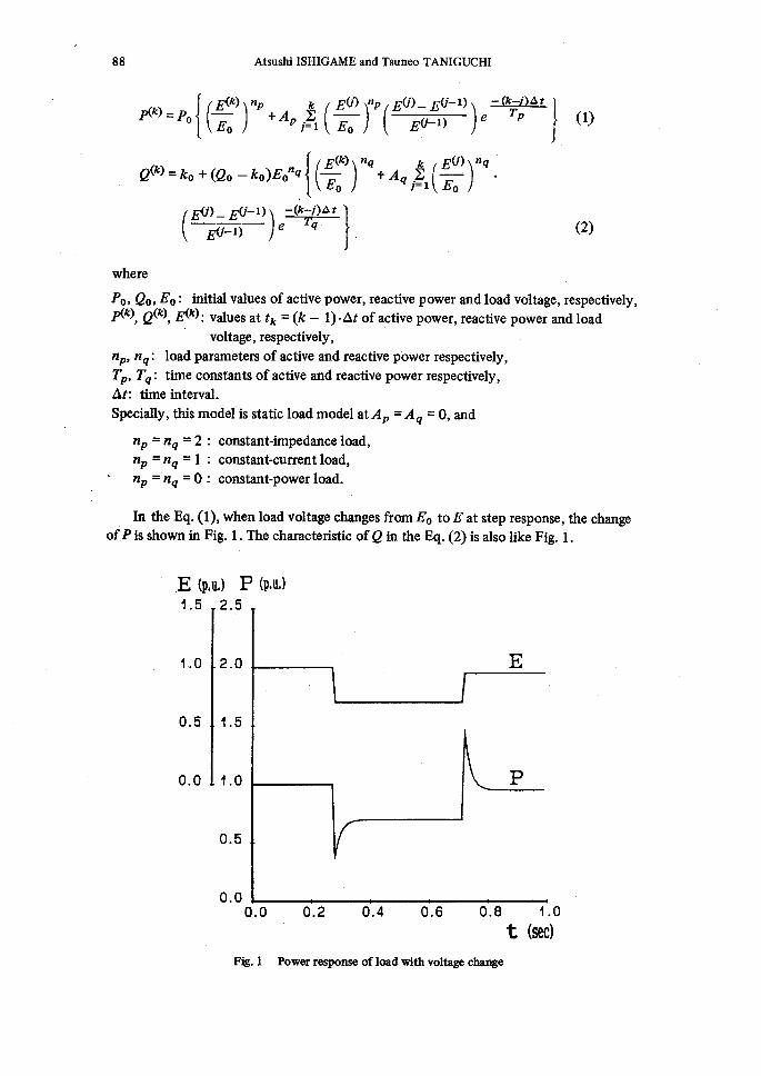
ln the Eq. (1), when load voltage changes from Eo to E at step response, the change
ofPis shown in Fig. 1. The characteristic ofe in the Eq. (2) is also like Fig. 1.
E1.5
<p,u,)
1,.O
O.5
o.o
2.
P (p,u,)
5
2.0
1.5
1.0
O.5
o.oo.o O.2 O.4 O.6 e.e 1.o
t (sec)
Ftg. 1 Power response of load with voltage change
Egst 7hansient Stability Evaiaation by Estimation ofElectrical Power Output 89
3. MathematicalFormulatiQn
3.l. Systemequation
The fbilowing assumptions are made for multimachine systems.
(1) Each synchronous machine is represented by a constant voltage behind its tran-
sient reactance.
(2) Mechanical power input is constant and the governor action is not taken into
account.(3) Each synchronous machine is a round-rotor machine.
Under the above assumptions, the motion of the ith machine is generally described
by the foilowing differential equation.
Mlrf2,2ii.D,(lfii/ii-g6,o)
' =P>ni-IEV 2 Gb・ -
- Pini - "Plei
ni.i (Clij Sin 6e' + Dij cos 6ij)
(i = 1, ".". n) 2, 3,
・(3)
n : number of machine in the system,
Di : dampingcoethcientofithmachne,Plgi : elecuical power output ofith machine,
6i : rotor angle in the reference frame,
6ij :6im6i, n n6o : centerofangle,6o= iZ.iMlr6ili.iM}
M} : inertia constant of ith machine,
P.i : mechanical power input ofith machne,
Ei : internal voltage behind transient reactance ofith machlne.
The case of constant impedance load, Clr, Dij are constants, but under considering
load characteristics, Clv, Dij・ change with load voltage, and resultant electrical power
output varies. For this reason, in solving the system's differential equations, sequential
calculations for loads are required.
3.2. Loadcalculation
The nodal equation which gives the current-voltage relation of a multi-machine
system is written approximately at the (k)th interval as follows:
IG (k) EG (k) IL(k) (= o) =y(k-i) EL(k) (4) i(k) (= o) E(k)
where
EG (k), EIL(k), E(k) : internal voltage vector of generators, load-bus voltage vector and
floating-bus voltage vector, respectivelyIG (k),IL(k),I(k): generator current vector, load-bus current vector, fioating-bus current
90・ Atsushi ISHIGAME and Tsuneo TANIGUCHI
vector, respectivelyYfa-i): modified nodal admittance matrix involvingload admttance YL pt-i)
By elmination of floating buses, '
IG(k) YGG YGL. EG(k) I]L(mp(=O) " Y]LG yLL(k-!) ,E,(k) (5)
and Eq.v(5) is written in the following hybrid form4)
[i,',10kil,1,l,ll-l[:it')l2i3Z.1'1,],!,tsi?,/o,),,]. (6'
hi2(k-1) = YGL (yLL(k-1))-i
h,,(k-1)=-(yLL(k-1))-i YLG
h22 (k-1) = (ILa (k-1)) -1
Then, admittance representation of ith load at (k)th interval is given by Eq. (7).
yLi(k)=<?i(mp-iei(k))/(ELi(k))2 ' (7) ' ' ' ' We now perform the matrix reduction on the Y matrix at the generator-buses as
.ib""kl '; lllfif2iiiZ`,k('bPoj' 2iie.M8.",Flilfi .!IYi,,YG`k' matri?c be denoted by yb(k){ and, qefine
By repeating this process for each interval, the loads are calculated with every tme.
3.3. Energy type Lyapunov function and stability evaluation
The transient energy function V, which is always defined fbr the post fault system,
can be given in Eq. (g)5,6).
V- Vk+% ' n =,F, Mlr dii2 /2 , ... vk + iS, pt (eiO - ei) +:.t-,i i.#.i Bijopi (cos e#o - cos eij)
+,#, i£.n, .6ist.leojt, GijEiE7 cosetid(ei+ei) ...px}, (g)
where
Yb = Gij + iBv,
ei = 6i - 6o: new rotor angle with respect to center of angle 6.,
eiO: initial stable point ofei ' ' ' '' '' ' '
' eij = ei - ej
]F;7st 7}zxnsient Stabtiity Evaluation by Estimation ofElectrieal Power Output
'wi: angularvelocityofithmachne, .,, ,.. ,,. ' '''Wo=d6oldt, ' '. 1. tt t tt --vei = wi = wi - wo,
vk: knetic energy dueto the relative angu1ar velociti6s, .. ・
Vb : potential energy due to the deviations ofangles from their stable points.
, ,t .. /. . ' 4'
3
2
Vcr
1
o
-- 1
vVk
.-----...-- "-'----r" "'`'-"r'"::
:'
:::t
Vp
Ftg. 2
Peij(p,u,)
1.4
1.2
1.0
O.8
Q.6
O.4
O.2
o.o
-6.2
t cr O.5 1.0t (sec)
Concept of the decision for eritical clearing tirne
fi-.:・-. 7
u][2 ]'
[3]
/-
Q.5 1.0
Fig. 3 Curve ofglectrical power outppt
.1.5e ij(rad)
9t
92 Atsushi ISHIGAME and Tsuneo TANIGUCHI
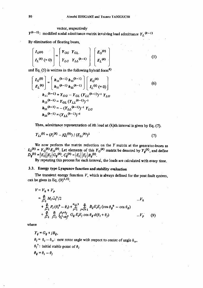
The value of energy function gradually increases during the fault, and by finding
the time where this value equals to the critical value Vb,, the critical clearing time for
stabihty can be determined.7)
This procedure is as follows:
(1) Construct an energy function V(D = V)t(t) + Vb (t),
(2) Find the time t" where dVb(t)/dt = O,
(3) Set V},(t") = Vbr,
(4) Find the critical clearing time t., by finding the time where Vb, = V(t).
4. PreposedMethod
4.1. Esimationofelectricalpoweroutput
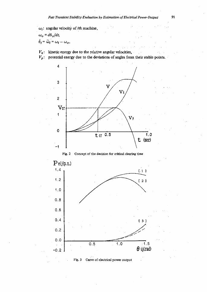
in this section, we investigate the estmation of electrical power output of gener-
ator which consider the nonlinearky of the load. Figure (3) shows an example of the
electrical power output curve along the sustained fault trajectory in a multmachne
system.
Curve [1] is the power-angle considering the constants load. Curve [2] is the
power-angle considering voltage dependence of the load. Curve [3] is AP.ij (eij) which
shows curve [1 ] -curve [2] . Hence, using this electrical power output 4i of ith machine
can be identified by the forms of Eq. (10) and Eq. (1 1). The curve identified by Eq.(10)
is ptustratedadotted line in Fig.3. '
APdj(eij・) L- Kl (eij - eije)i/3
+ K2(eij - eijO) + K3 (eg - eije)3
n"Plei = i Peij'
pbij = ctr sin eij + Do・ cos eij・
-{Kl (eij・ - etie)i/3 + K2 (eij - eij・e) + K3 (eij - e ijO)3}
(1O)
(1 1)
[he first and second term of right hand side in the Eq. (1!) are the power con-
sidering constant impedance load, and the third term indicates the effect of the voltage
dependence of load. The Constants Kl, K2, K3 are identified with the method ofleast
squares.
'Ihe merit of Eq. (1 1) is as foilows:
(1) The effect of the voltage dependence of load can be dealt with correctively, because
the nonlmearity ofelectrical power output is almost expressed by Eq. (10).
(2) Energy function is analytically calculated, because electrical power output is
expressed by polynomial of relative rotor arigle of generators.
(3) Approximate value ofcritical energy is easily obtained.
4.2. Approximationofswing
in the case, considering the voltage dependence ofload, sequential computation of
system load is required for the process of calcuiation of the sustained fault trajectory.
So we propose an approximate solution of the swing equation, fbr the fast determina-
tion of the sustained fault trajectory and for the estimation of electrical power output.

jF2zst 77ansient Stabtiity Evaluation by Estimetion ofE:lectrical fower Ouiput 93
The approximate solution derives as follows :
(1) Estimate the values of a4iO, Bi and 7} of ith machne, by solving the Eq. (3) for a
few steps after the fault occurred. ・'(2) Using these values,
d6i,wi = dt
= att, ale= qie +k¥1
-k*AtZ 6ie Ti
(12)
(3) Making use of the above wi,
6i --- 6i O+Icoidt (13)
where
ori: angular acceleration ofith machine,
6i: correction constant ofangular acceleration ofith machine,
11r: tme constant of ith machine,
6iO : initial rotor angle of ith machine,
m=tlAt.
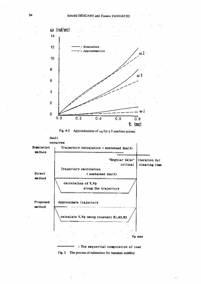
Figure 4 shows 6 and (D fbr the sustained fault. Each process ofsimulation,
and proposed method in this paper is Mustrated in Fig. 5. Double line of Fig. 5
part that the sequential computation of load is required.
direct
is the
6 (rad)
6
4
2
o
: Simulation
- --:Approximation
f
-
4
-
7
-
7
'
7/
'
. 4621
/
'
/
-
63
61
o.o O.2 O.4 O.6 O.8
t (sec)
Fig. 4-1 Approximation of・6i for a 3 machine system
94 Al sushi ISHIGAME and Tsuneo TANIGUCHI
w14
12
10
B
6
4
2
o
.(rad!sec)
:
-- T':
4q
-
SimulationApproximati6ri.
77
fr
7
Z
7
7
f
;--
f
7!-
f
-
q
-
7 Z
-
/
-
/
!
/
!
'
ul 2
tu 3
'
Simulation
method
Direct
method
Propesed
method
o.o
Ftg. 4-2
fau1t
oqcurred
O.2 O.4 O.6 O. t (see)
'Approximatigp of wi for a 3 mp, , chine systegi'
.--------- to 1 e
rred
Trajectoryealculation<sustainedfault>
"Regularfalsi"
'eriticalTrajectorycalculation'"
<sustainedfault>
.iteratio
elearin
ealculationofV,Vp
alongthetrajectory'
'Approxilnatetrajectory
-H-- t----"--nt-t--+---T---L-r--- .--------------
ealculateV,VpusingconstantKl,k2,K3'
tt
-・. .'. . Vp' max
nv- :The sequential computation of load
Fig. 5 - -The process ofestiipation for manst'ent stability
for
time
fust 71,unsient Stability'Evaluati'bn by Elstirnation ofE:lectrical Power Ouiput 95
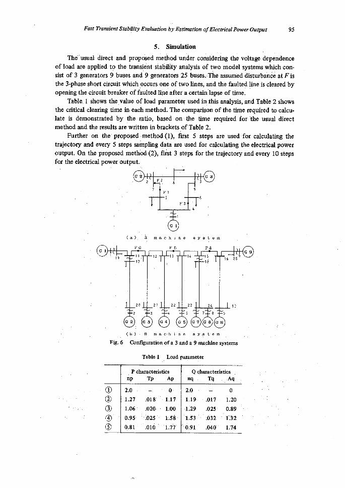
5. Simulation
The dsual direct and proposed method under considering the voltage d6pendence
of load are applied tg the translgnt stability analysis of two model systems which con-
sist of 3 gen. erators 9 buses and 9 generators 25 buses.-The assumed disturbahee atFis
the 3-phase short circuit which ,occurs one of two lines, and the faulted 1ine is cleared by
opening the circuit breaker of faulted line after a certain lapse of time.
Table.1 shows the value of load parameter used in this analysis, and Table 2 shows
the critical clearing time in each method. The comparison of the ttme required to calcu-
late is demonstrated by the ratio, based on the tme required for the usual direct
method and the resuks are written in brackets of Table 2.
Further on the proposed method(1), first 5 steps are used for calculating the
trajectory and every S steps sampling data are used for calculating the electrical power
output. On the proposed method (2), fitst 3 steps for the trajectory and every 10 steps
for the electrical power output.
G22 F.2
7
Fl.s
8
F3
1
9
Gl
4
3
6
G3
(a). 3 machine system
F6.FoFF4Gl G91
'19
.1311,
17
20
12
21 22
14
23.
15
lg
24
1625
10
G 22
3G3G4 4
55G'
78G7G8G6
6
Fig.6
(b) / 9. ..rn,a c/ h. i・ n e. s y・ ,F t・e rtt -.
Condguration of a 3 apd a 9 maphinp systemS
Table 1 Load parqmeter
..Pcharactesist.ics Qqharacteristics
np Tp Ap nq Tq. ,Aq
@ 2.0-・ -,e・ 2.0
- o
Q 1.27 .O18' -- 1.17・ 1-.19- .O17 1.20
@ -1.061 .o2ei 1.00 -1:29- .025・ 'O.89
@ O,95' -le25' i・is8i 'l.S3' ・.032''1'132'
(!l) O.81i .O10' '' i.7'7' ・'oLgl .040' 1:74
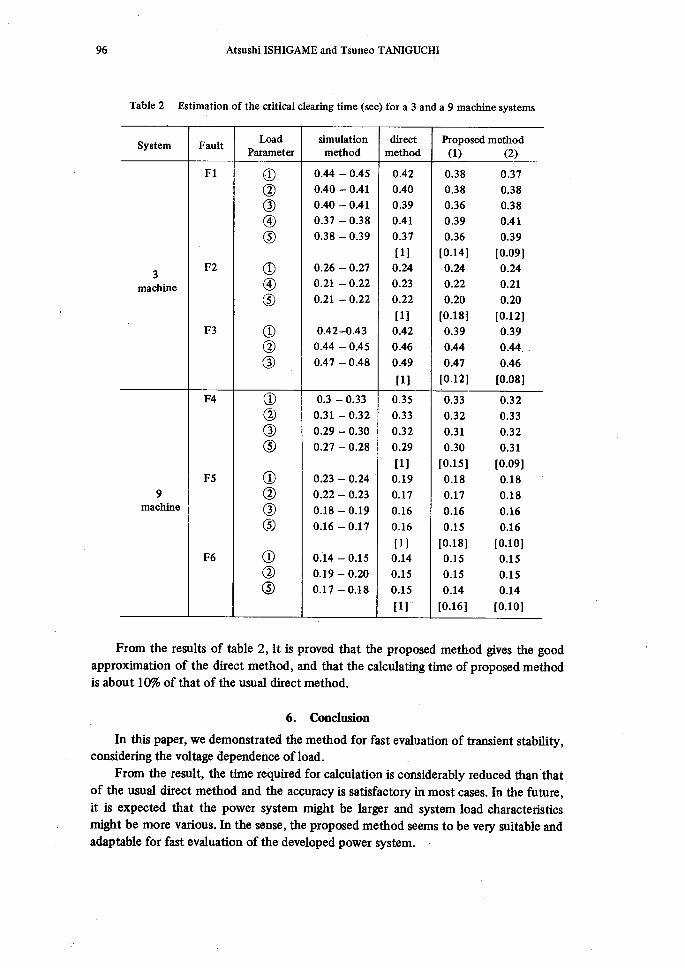
96 Atsushi ISHIGAME and Tsuneo TANIGUCHI
1
Table 2 Estimation of the critical clearing time (sec) for a 3 and a 9 machine systems
System FaultLoad
Parameter
simulation
methoddirect
methodProposedmethod
(1)(2)Fl o O.44-O.45 O.42 O.38O.37
@ O.40-O.41 O.40 O.38O.38@ O.40-O.41 O.39 O.36O.38@ e.37-O.38 O.41 O.39O.41@ O.38-O.39 O.37 O.36O.39
[1] [O.141IO.09]
3F2 ¢ O.26-027 O.24 O.MO.24
machine' @ e.21-022 O.23 O.22O.21@ O.21-O.22 O.22 o.2eo.2o
[1] [O.18][O.12],
F3 @ O.42-O.43 O.42 O.39O.39@ O.44-O.45 O.46 O.44O.44..@ O.47-O.48 O.49 O.47O.46
[11 [O.12]fO.08]
F4 o O.3-O.33 O.35 O.33O.32@ O.31-O.32 O.33 O.32O.33@ O.29-O.30 O.32 O.31O.32@ O.27-e.28 O.29 O.30O.31
[1] [O.15][O.09]F5 @ O.23-O.24' O.19 O.18O.18
9 @ O.22-O.23 O.17 O.17O.18rnachine @ O.18-O.19 O.16 O.16O.16
@ O.16-O.17 O.16 e.15O.16[1] [O.181[O.10]
F6 @ Oi4-O.15 O.14 O.15O.15@ o.lg-o.2e O.15 OJ5O.15@ O.17-O.18 O.15 O.14O.14
[1]' [O.16]{O.10]
From the results of table 2, it is proved that the proposed method gives the good
approximation of the direct method, and that the calculating time of proposed method
is about 1O% of that of the'usual direct method.
6. Conclusion
in this paper, we demonstrated the method for fbst evaluation of transient stability,
constdering the voltage dependence ofload. , From the result, the time required for calculation is considerably reduced than that
of the usual direct method and the accuracy is satisfactory in most cases. In the future,
it is expected that the power system might be largor and system load characteristics
might be more various. In the sense, the proposed method seems to be very suitable and
adaptable for fbst evaluation of the developed power system.

I72zst 7)ransient Stabtiity Evalaation bj, Elstimation ofETectrical JPbwer Ouiput 97
1)2)3)4)
5)
6)
7)
Refetences
M. Musatizi, et aL, IEEE [Ittans., VoL EC-1, No. 4, pp34-38, (1986)
N. Kakimoto, et al., PE87-60, I.E.E. of JapanY. Kojima, et al., 'Lecture 982 in annual Meeting of I.E.E.- of Japan (1988)
M. Gotou, et aL, Trans.'l.EEJ., 52-B85 (1977)
T. Athay, et aL, IEEE Trans., Vol. PAS-98, No. 2, pp.573-584, (1979)
K. Maruyama, et at, PE-87-61, LE.E. of Japan
N. Kakimoto, et al., Trans. I.E.E. of Japan, Vol. 98, No. 5/6
f