fas-420-tm aspirating smoke detector - bosch...
TRANSCRIPT
FAS-420-TM Aspirating Smoke DetectorFAS-420-TM
en Operation Guide

FAS-420-TM Aspirating Smoke Detector Table of Contents | en 3
Bosch Sicherheitssysteme GmbH Operation Guide F.01U.088.878 | 4.1 | 2010.11
Table of Contents
1 General 61.1 Introduction 61.2 Safety Instructions 61.3 Warranty 61.4 Copyright 61.5 Disposal 7
2 Technical Specifications 82.1 Product Description 82.2 Areas of Application 102.3 System Overview 122.4 Functions 132.5 FAS-420-TM Series Aspirating Smoke Detectors and Accessories 172.5.1 Overview 172.5.2 FAS-420-TM Series Connections 182.5.3 FAS-420-TM Displays 192.5.4 FAS-420-TM-R Displays 202.5.5 FAS-420-TM-RVB Displays 212.5.6 FAS-ASD-DIAG Diagnostic Software 212.5.7 Remote Indicators 222.6 Pipe System Components 222.6.1 Overview 222.6.2 Air Sampling Openings 232.6.3 Ceiling Lead-through 252.6.4 Air-Return Pipe for Pressure Areas and Atmospheric Loads 252.6.5 Water Separator for Humid Areas 262.7 Scope of Delivery: Smoke Aspiration System 282.8 Technical Specifications 302.8.1 FAS-420-TM Series Aspirating Smoke Detectors 302.8.2 Pipe system 312.8.3 Smoke Aspiration System Components 31
3 Planning 333.1 Regulations 333.2 Principles of Pipe Planning 343.3 Airflow Monitoring 363.4 Defining the Response Sensitivity 373.5 Planning Limits 383.6 Standard Pipe Planning 393.6.1 Determining the Necessary Accessories 393.6.2 Pipe Planning with Pipe Accessories 393.6.3 Planning with Air Filter 413.6.4 Opening Diameter 423.7 Planning with Single-hole Monitoring 443.7.1 I-pipe system 443.7.2 U-pipe system 45
4 en | Table of Contents FAS-420-TM Aspirating Smoke Detector
F.01U.088.878 | 4.1 | 2010.11 Operation Guide Bosch Sicherheitssysteme GmbH
3.7.3 M-pipe system 463.7.4 Double U-pipe system 483.8 Simplified pipe planning 493.8.1 I-Pipe System - Simplified Planning 493.8.2 U-Pipe System - Simplified Planning 503.8.3 U-pipe System - Simplified Planning 503.8.4 Double U-Pipe System - Simplified Planning 513.9 Planning for forced airflow 523.10 Power Supply 55
4 Installing the Aspirating Smoke Detector 584.1 General 584.2 Setting the Detector Address 584.3 Installing the Unit 594.4 Connection to the Fire Panel 624.4.1 Electrical Connection 624.4.2 LSN Configuration 634.4.3 Parameter Settings via Programming Software 634.4.4 Settings via the FAS-ASD-DIAG Diagnostic Software 644.5 Data Logging 65
5 Installation of the Pipe System 665.1 Length Change of the Pipe System 685.2 Air Sampling Openings 685.3 Ceiling Lead-through 705.4 Monitoring with Forced Airflow 715.4.1 Detection at Intake and Exhaust Openings 715.4.2 Detection in the Bypass 715.5 Air filter 725.5.1 Installing the Air Filter Box 725.6 Air-return pipe 725.7 Three-way tap 735.8 Water separator 735.9 Test Adapter 74
6 Commissioning 766.1 Preparation 766.2 Detector Module Commissioning 766.3 Calibrating the Airflow Sensor 776.3.1 Air-Pressure-Independent Calibration 776.3.2 Air-Pressure-Dependent Calibration 776.4 Checking the Detector Module and Alarm Transfer 796.5 Checking Malfunction Transmission 806.6 Checking Airflow Monitoring 806.7 Functional Test of Airflow Sensors 816.7.1 Preparations for the Functional Test 816.7.2 Conducting the Functional Test 826.8 Fire Source Identification Commissioning 85
FAS-420-TM Aspirating Smoke Detector Table of Contents | en 5
Bosch Sicherheitssysteme GmbH Operation Guide F.01U.088.878 | 4.1 | 2010.11
7 Maintenance 867.1 Visual check 867.2 Detector Module and Alarm Transfer 867.3 Pipe System 867.4 Replacing the Detector Module 877.5 Replacing the Air Filter in the Housing Base 887.6 Filter Change on the Filterbox 897.7 Blowing-out Process for the Pipe System 907.8 Checking the Airflow Sensor Calibration 907.9 Testing the Fire Source Identification 927.10 Airflow monitoring 927.11 Malfunction Transmission 927.12 Maintenance Intervals 92
8 Appendix 948.1 DIP Switch Settings for Detector Addresses 958.2 Planning without air filter 978.2.1 Without any other pipe accessories 978.2.2 With water separator 978.3 Planning with Air Filter 988.3.1 Without Any Other Pipe Accessories 988.3.2 With water separator 988.4 Test Log for Aspirating Smoke Detectors in the FAS-420-TM Series 99
Index 101

6 en | General FAS-420-TM Aspirating Smoke Detector
F.01U.088.878 | 4.1 | 2010.11 Operation Guide Bosch Sicherheitssysteme GmbH
1 General
1.1 IntroductionThis operation guide describes the smoke aspiration systems featuring FAS-420-TM series Aspirating Smoke Detectors and the associated aspiration pipe system.The FAS-420-TM designation in this operation guide refers to all FAS-420-TM series (FAS-420-TM, FAS-420-TM-R, FAS-420-TM-RVB) versions. Specific references are made to differences between the individual versions.
1.2 Safety InstructionsThe following symbols identify points in this operation guide that require particular attention in order to guarantee smooth operation and prevent damage.
1.3 WarrantyThe operation guide is subject to technical modification without prior notice and makes no claim to completeness. Our "delivery and installation conditions" apply as a matter of principle. Warranty and liability claims in case of personal injury and property damage cannot be asserted if they are based on one or more of the following causes:– Insufficient attention to the instructions with respect to planning, installation of the
aspirating smoke detector, installation of the pipe system, commissioning and maintenance
– Use of the smoke aspiration system contrary to the regulations– Insufficient monitoring of wearing parts– Faulty repairs– Arbitrary constructional changes to the smoke aspiration system– Acts of God.
Bosch Sicherheitssysteme GmbH, hereinafter referred to as Bosch, assumes no liability for damage or malfunction arising through failure to comply with this operation guide.
1.4 CopyrightThe copyright to this operation guide remains with Bosch.
NOTICE! Operational malfunction can be prevented and operational improvements can be achieved by observing these instructions.
CAUTION! This symbol warns against actions and behavior which, if disregarded, could cause property damage.
WARNING! This symbol warns against actions and behavior which, if disregarded, could cause personal injury.
CAUTION! The equipment may only be installed by authorized and qualified personnel!
FAS-420-TM Aspirating Smoke Detector General | en 7
Bosch Sicherheitssysteme GmbH Operation Guide F.01U.088.878 | 4.1 | 2010.11
This operation guide is intended exclusively for installation engineers and their employees. Reprinting this operation guide or extracts thereof is permitted for internal purposes only.
1.5 Disposal
Unusable electrical and electronic devices or modules must not be disposed of with normal household refuse. They must be disposed of in compliance with the applicable regulations and directives (e.g. WEEE in Europe).
8 en | Technical Specifications FAS-420-TM Aspirating Smoke Detector
F.01U.088.878 | 4.1 | 2010.11 Operation Guide Bosch Sicherheitssysteme GmbH
2 Technical Specifications
2.1 Product DescriptionAspirating Smoke Detectors from the FAS-420-TM series are active fire detection devices that are connected directly to the Local SecurityNetwork (LSN) improved version for early fire detection. They are used for space and equipment protection as well as for monitoring air conditioning units or ducts (provided that the FAS-420-TM is installed outside of these units or ducts). You can also pinpoint the exact location of the fire using the innovative fire source identification operation.
Local SecurityNetwork (LSN) improved versionFAS-420-TM series Aspirating Smoke Detectors were developed specifically for connection to Bosch fire panels with LSN improved version technology and therefore offer the following extended features:– Flexible network structures, including T-tapping with no additional elements– Up to 254 LSN-improved elements per loop or stub line– Unshielded cable can be used.The FAS-420-TM series also offers all the established benefits of LSN technology. The operating data and fault messages can be read off the fire panel's operating and display unit.
VariantsAll FAS-420-TM series Aspirating Smoke Detectors have LED displays for operating mode, malfunction and main alarm, and also offer an infrared diagnostics port. In addition to this, the FAS-420-TM-R and FAS-420-TM-RVB variants offer an optical fire location display for up to five zones. The FAS-420-TM-RVB also includes a pre-alarm display and a 10-segment smoke level display.
Fire source identificationInnovative fire source identification technology allows the exact location of the fire to be pinpointed by monitoring up to five distinct neighboring zones. To enable the emergency response teams to intervene as quickly as possible, the location of the fire can also be identified using the FNS-420-R LSN Strobes, for example, which are assigned to the various monitoring ranges.
SensitivityFAS-420-TM series Aspirating Smoke Detectors have a response sensitivity of 0.5%/m to 2%/m light obscuration. The sensitivity levels can be selected according to the area of application using the fire panel's programming software (see Section 4.4.3 Parameter Settings via Programming Software, page 63). The smoke level display on the FAS-420-TM-RVB model allows a response sensitivity of 0.05%/m to 0.2%/m light obscuration.With the new high-power light source technology, a broad detection spectrum including all standardized fires is achieved (see Section 3.4 Defining the Response Sensitivity, page 37).
LOGIC×SENSThe intelligent signal processing LOGIC·SENS distinguishes between deception variables and fire events in order to prevent false alarms.
Reliable airflow monitoringAnalogous to point-type smoke detectors, which are monitored electronically for wire breaks and short-circuits, highly sensitive and dependable airflow monitoring is required for smoke aspiration systems. The airflow sensors used in the FAS-420-TM series reliably detect malfunctions such as pipe breakage or obstructions in the air sampling openings.
FAS-420-TM Aspirating Smoke Detector Technical Specifications | en 9
Bosch Sicherheitssysteme GmbH Operation Guide F.01U.088.878 | 4.1 | 2010.11
Airflow monitoring is temperature-compensated and can be set depending on the air pressure.
Plug-and-playThe plug-and-play function makes the installation and commissioning of the aspirating smoke detectors simple. The housing base is preinstalled on site. By preinstalling the detector module for standard applications, the FAS-420-TM series Aspirating Smoke Detectors are ready for operation as soon as they are inserted into the housing base.
Patented air sampling openingsThe air sampling openings of the pipe system require clearly defined bore diameters that depend on the planning and design. These precise air sampling openings are created using patented aspiration reducing film sheets, marking tape, and clips, which not only permit easy installation, but also prevent "whistling" noises. Another advantage is the quick and easy detection and checking of the air sampling opening diameters.
Point-type detector projectionThe system’s aspiration points can be equated with point-type smoke detectors. The monitoring areas can therefore be planned in accordance with the applicable national regulations.
DiagnosticsA system with FAS-ASD-DIAG Diagnostic Software, which enables quick and convenient error containment, is available for maintenance and service. The current and stored (max. 72 hours) unit status is read out to the diagnostic appliance via the unit's infrared port. The data is transmitted from the diagnostic appliance to a laptop via a USB cable.
Selecting the fan voltageThe fan voltage can be increased for special planning from 9 V to 12 V via the fire panel's programming software. In addition, the fan voltage can be increased up to 13.5 V in intervals of 1 V via the FAS-ASD-DIAG Diagnostic Software. The increase in the fan voltage causes an increase in the air transport speed and therefore reduces detection time.
Extensive pipe accessoriesThe extensive range of accessories enables the FAS-420-TM aspirating smoke detectors to be used even in the most difficult conditions. Products from air filters and condensate separators to blowing-out systems increase the service life in extremely dusty, damp and cold environmental conditions.
10 en | Technical Specifications FAS-420-TM Aspirating Smoke Detector
F.01U.088.878 | 4.1 | 2010.11 Operation Guide Bosch Sicherheitssysteme GmbH
2.2 Areas of ApplicationThanks to their detection principle, FAS-420-TM aspirating smoke detectors represent an extremely versatile fire protection solution.
PrincipleAir samples are taken from the monitoring range by a pipe system with defined aspiration borings and then fed to the detector module.This is especially well-suited for areas in which point-type detectors cannot be used or can only be used under certain circumstances. These include:– Areas that are difficult to access, in which point detectors are difficult to install and
maintain– Air-conditioned areas– Areas that require the earliest detection possible– Areas with a height greater than that allowed for point detectors– Areas in which point detectors are not desired for aesthetic reasons– Areas in which strong electromagnetic fields occur– Areas that are exposed to high or low temperatures– Areas with contaminated air that require filter elements– Areas that must be protected against vandalism.
Space protectionThe FAS-420-TM series is suitable for monitoring areas such as– Those with double floors, false ceilings– Tunnels, ducts, barely accessible hollow spaces– Storage, high-rise warehouses, elevator shafts– Museums, cultural institutions– Hotel rooms, hospital rooms, offices, prison cells, train compartments
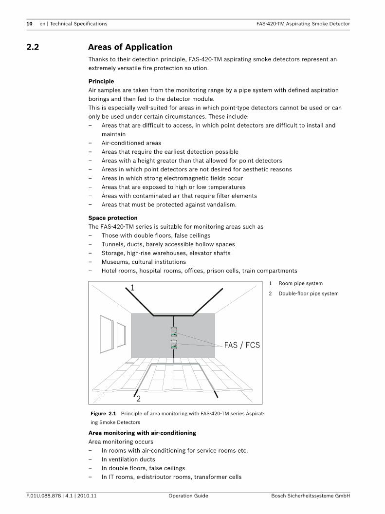
Area monitoring with air-conditioningArea monitoring occurs– In rooms with air-conditioning for service rooms etc.– In ventilation ducts– In double floors, false ceilings– In IT rooms, e-distributor rooms, transformer cells
Figure 2.1 Principle of area monitoring with FAS-420-TM series Aspirat-
ing Smoke Detectors
1 Room pipe system
2 Double-floor pipe system
FAS / FCS
1
2
T IT AN U S M IC R O ·S EN S ®
E
D
C
B
A
10987654321
T IT AN U S M IC R O ·S EN S ®
E
D
C
B
A
10987654321
FAS-420-TM Aspirating Smoke Detector Technical Specifications | en 11
Bosch Sicherheitssysteme GmbH Operation Guide F.01U.088.878 | 4.1 | 2010.11
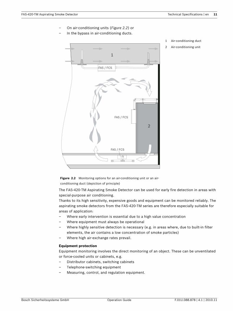
– On air-conditioning units (Figure 2.2) or– In the bypass in air-conditioning ducts.
The FAS-420-TM Aspirating Smoke Detector can be used for early fire detection in areas with special-purpose air conditioning.Thanks to its high sensitivity, expensive goods and equipment can be monitored reliably. The aspirating smoke detectors from the FAS-420-TM series are therefore especially suitable for areas of application:– Where early intervention is essential due to a high value concentration– Where equipment must always be operational– Where highly sensitive detection is necessary (e.g. in areas where, due to built-in filter
elements, the air contains a low concentration of smoke particles)– Where high air-exchange rates prevail.
Equipment protectionEquipment monitoring involves the direct monitoring of an object. These can be unventilated or force-cooled units or cabinets, e.g.– Distributor cabinets, switching cabinets– Telephone-switching equipment– Measuring, control, and regulation equipment.
Figure 2.2 Monitoring options for an air-conditioning unit or an air-
conditioning duct (depiction of principle)
1 Air-conditioning duct
2 Air-conditioning unit
FAS / FCS
FAS / FCS
FAS / FCS
1
2
12 en | Technical Specifications FAS-420-TM Aspirating Smoke Detector
F.01U.088.878 | 4.1 | 2010.11 Operation Guide Bosch Sicherheitssysteme GmbH
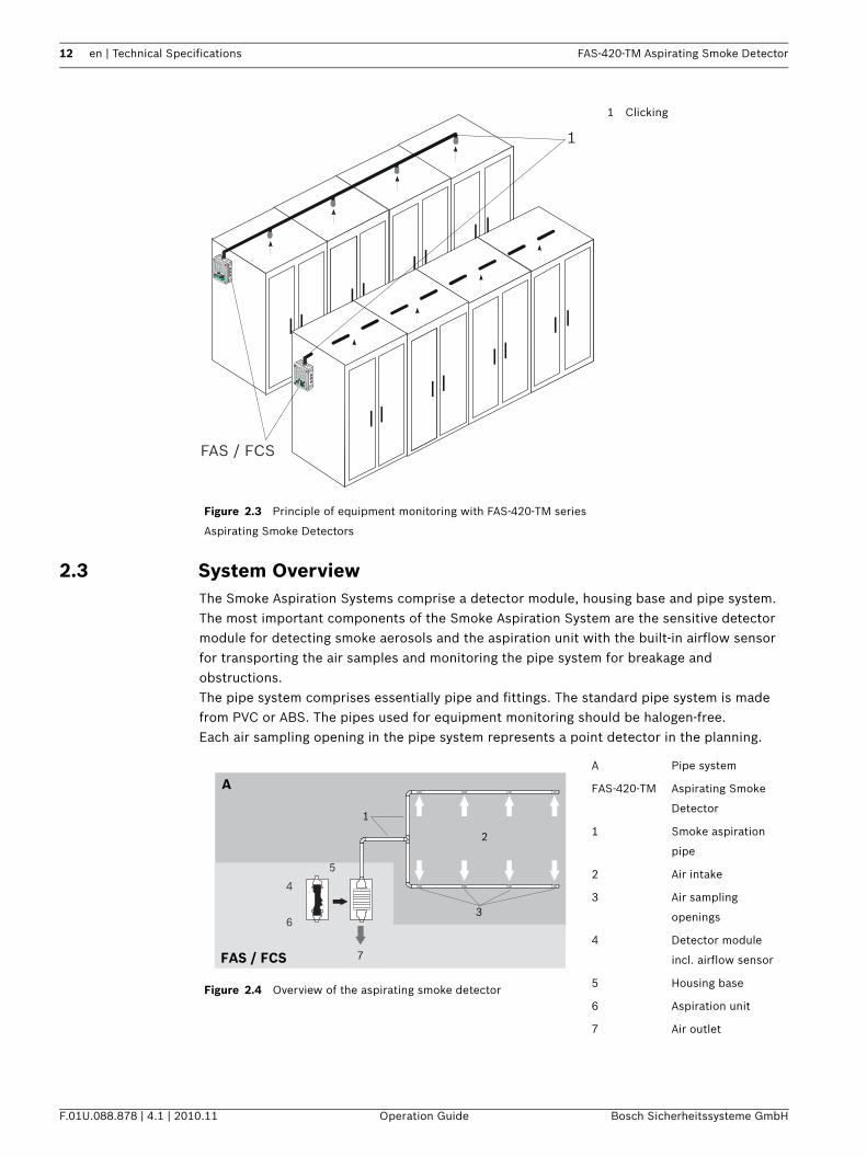
2.3 System OverviewThe Smoke Aspiration Systems comprise a detector module, housing base and pipe system.The most important components of the Smoke Aspiration System are the sensitive detector module for detecting smoke aerosols and the aspiration unit with the built-in airflow sensor for transporting the air samples and monitoring the pipe system for breakage and obstructions.The pipe system comprises essentially pipe and fittings. The standard pipe system is made from PVC or ABS. The pipes used for equipment monitoring should be halogen-free.Each air sampling opening in the pipe system represents a point detector in the planning.
Figure 2.3 Principle of equipment monitoring with FAS-420-TM series
Aspirating Smoke Detectors
1 Clicking
1
FAS / FCS
Figure 2.4 Overview of the aspirating smoke detector
A Pipe system
FAS-420-TM Aspirating Smoke
Detector
1 Smoke aspiration
pipe
2 Air intake
3 Air sampling
openings
4 Detector module
incl. airflow sensor
5 Housing base
6 Aspiration unit
7 Air outlet
2
7
3
1
A
FAS / FCS
4
6
5
FAS-420-TM Aspirating Smoke Detector Technical Specifications | en 13
Bosch Sicherheitssysteme GmbH Operation Guide F.01U.088.878 | 4.1 | 2010.11
To guarantee reliable operation even under the most difficult conditions (clean rooms, recycling area), there are numerous accessories available, such as air filters and water separators; see Section 2.6 Pipe System Components, page 22.
2.4 FunctionsAir samples are taken from the area to be monitored via the aspiration unit. They are fed via a pipe system with defined air sampling openings to the sensitive detector module (see Figure 2.4).
DetectionDepending on the response sensitivity of the detector module in use and the alarm threshold programmed, the FAS-420-TM aspirating smoke detector triggers the alarm when the corresponding air obscuration threshold is reached. The alarm is displayed via the pre-alarm or main alarm LED on the device and forwarded to a connected fire panel.Various delay times can be set for the alarm thresholds, as well as for displaying and transferring malfunctions (see Section 4.4.3 Parameter Settings via Programming Software, page 63). Alarm messages are saved and are reset after the cause has been eliminated.
LOGIC×SENSThe LOGIC·SENS intelligent signal processing compares the measured smoke level with known disturbance variables and decides whether something is an alarm or deception. LOGIC SENS can be activated or deactivated using the fire panel's programming software.
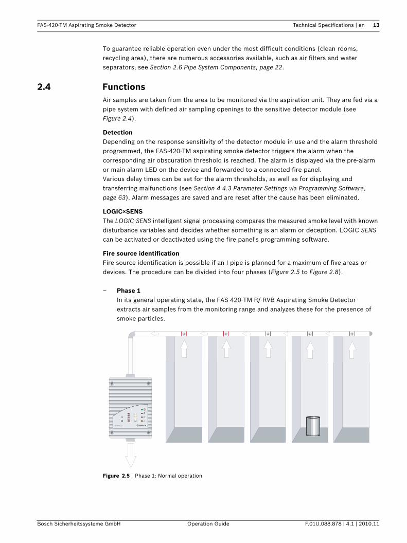
Fire source identificationFire source identification is possible if an I pipe is planned for a maximum of five areas or devices. The procedure can be divided into four phases (Figure 2.5 to Figure 2.8).
– Phase 1In its general operating state, the FAS-420-TM-R/-RVB Aspirating Smoke Detector extracts air samples from the monitoring range and analyzes these for the presence of smoke particles.
Figure 2.5 Phase 1: Normal operation
E
D
C
B
A
10987654321
FAS-420-TM series
14 en | Technical Specifications FAS-420-TM Aspirating Smoke Detector
F.01U.088.878 | 4.1 | 2010.11 Operation Guide Bosch Sicherheitssysteme GmbH
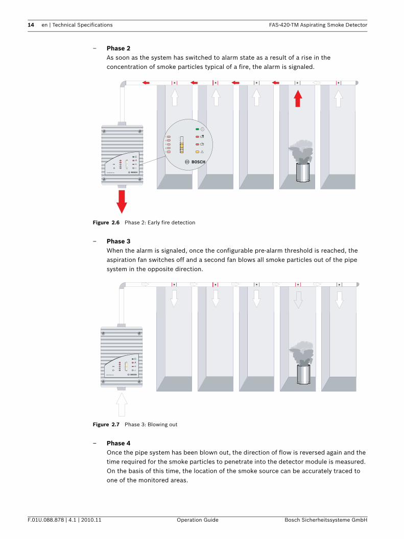
– Phase 2As soon as the system has switched to alarm state as a result of a rise in the concentration of smoke particles typical of a fire, the alarm is signaled.
Figure 2.6 Phase 2: Early fire detection
– Phase 3When the alarm is signaled, once the configurable pre-alarm threshold is reached, the aspiration fan switches off and a second fan blows all smoke particles out of the pipe system in the opposite direction.
Figure 2.7 Phase 3: Blowing out
– Phase 4Once the pipe system has been blown out, the direction of flow is reversed again and the time required for the smoke particles to penetrate into the detector module is measured. On the basis of this time, the location of the smoke source can be accurately traced to one of the monitored areas.
E
D
C
B
A
10987654321
FAS-420-TM series
E
D
C
B
A
10
9
8
7
6
5
4
3
2
1
E
D
C
B
A
10987654321
FAS-420-TM series
FAS-420-TM Aspirating Smoke Detector Technical Specifications | en 15
Bosch Sicherheitssysteme GmbH Operation Guide F.01U.088.878 | 4.1 | 2010.11
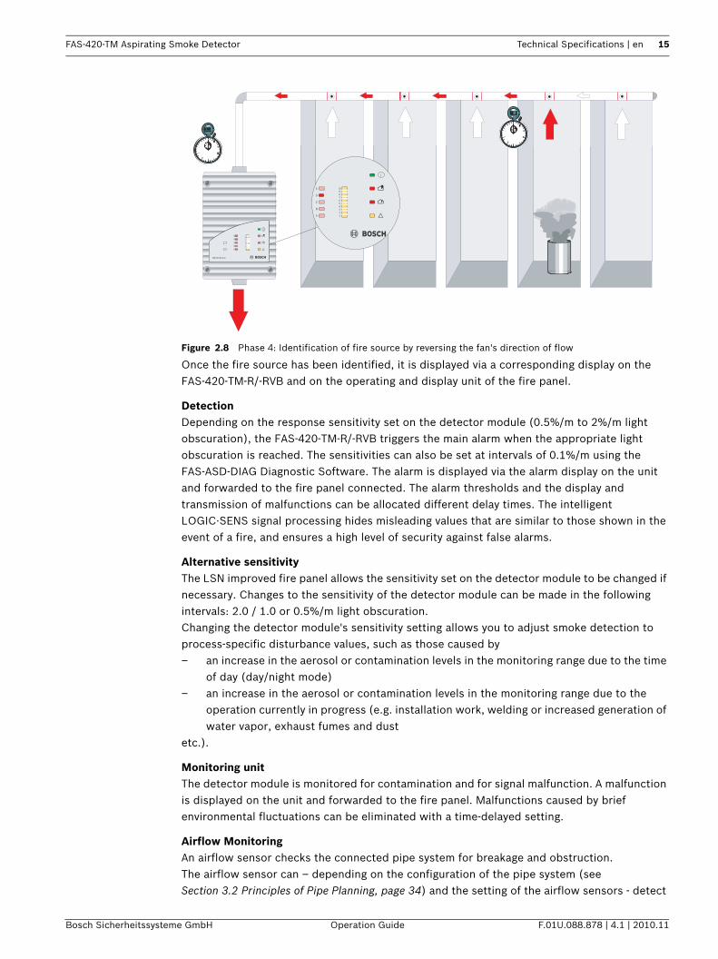
Figure 2.8 Phase 4: Identification of fire source by reversing the fan's direction of flow
Once the fire source has been identified, it is displayed via a corresponding display on the FAS-420-TM-R/-RVB and on the operating and display unit of the fire panel.
DetectionDepending on the response sensitivity set on the detector module (0.5%/m to 2%/m light obscuration), the FAS-420-TM-R/-RVB triggers the main alarm when the appropriate light obscuration is reached. The sensitivities can also be set at intervals of 0.1%/m using the FAS-ASD-DIAG Diagnostic Software. The alarm is displayed via the alarm display on the unit and forwarded to the fire panel connected. The alarm thresholds and the display and transmission of malfunctions can be allocated different delay times. The intelligent LOGIC·SENS signal processing hides misleading values that are similar to those shown in the event of a fire, and ensures a high level of security against false alarms.
Alternative sensitivityThe LSN improved fire panel allows the sensitivity set on the detector module to be changed if necessary. Changes to the sensitivity of the detector module can be made in the following intervals: 2.0 / 1.0 or 0.5%/m light obscuration.Changing the detector module's sensitivity setting allows you to adjust smoke detection to process-specific disturbance values, such as those caused by – an increase in the aerosol or contamination levels in the monitoring range due to the time
of day (day/night mode) – an increase in the aerosol or contamination levels in the monitoring range due to the
operation currently in progress (e.g. installation work, welding or increased generation of water vapor, exhaust fumes and dust
etc.).
Monitoring unitThe detector module is monitored for contamination and for signal malfunction. A malfunction is displayed on the unit and forwarded to the fire panel. Malfunctions caused by brief environmental fluctuations can be eliminated with a time-delayed setting.
Airflow MonitoringAn airflow sensor checks the connected pipe system for breakage and obstruction.The airflow sensor can – depending on the configuration of the pipe system (see Section 3.2 Principles of Pipe Planning, page 34) and the setting of the airflow sensors - detect
E
D
C
B
A
10987654321
FAS-420-TM series
E
D
C
B
A
10987654321
16 en | Technical Specifications FAS-420-TM Aspirating Smoke Detector
F.01U.088.878 | 4.1 | 2010.11 Operation Guide Bosch Sicherheitssysteme GmbH
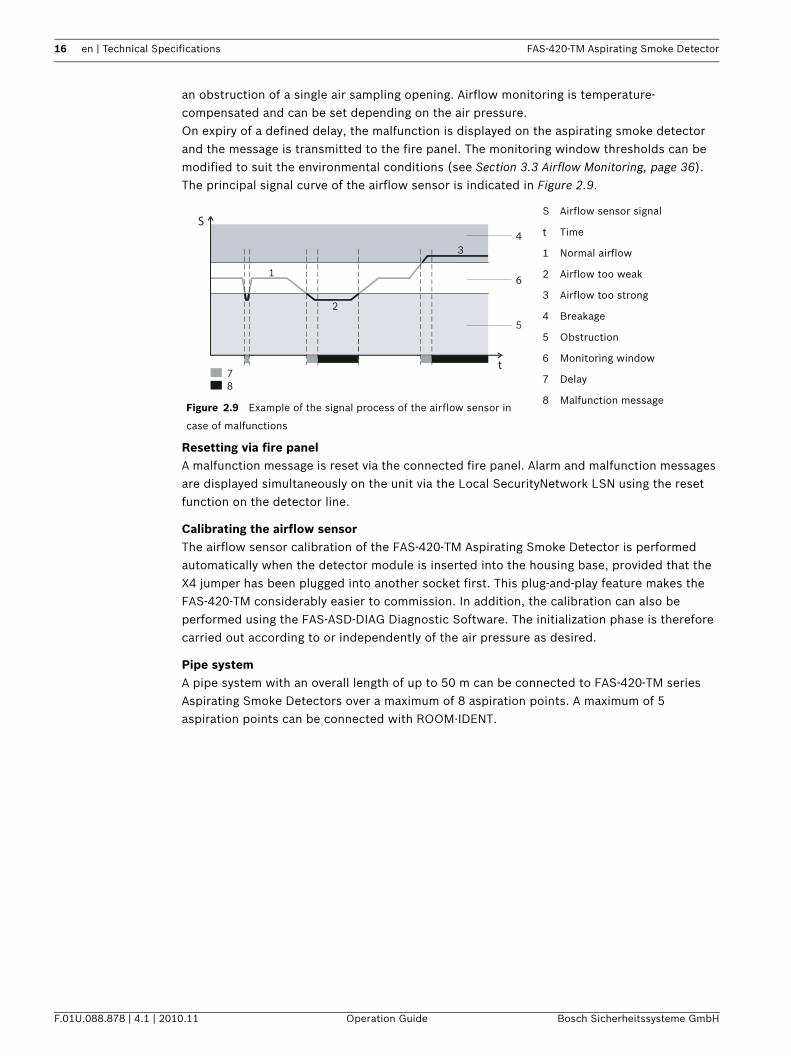
an obstruction of a single air sampling opening. Airflow monitoring is temperature-compensated and can be set depending on the air pressure.On expiry of a defined delay, the malfunction is displayed on the aspirating smoke detector and the message is transmitted to the fire panel. The monitoring window thresholds can be modified to suit the environmental conditions (see Section 3.3 Airflow Monitoring, page 36).The principal signal curve of the airflow sensor is indicated in Figure 2.9.
Resetting via fire panelA malfunction message is reset via the connected fire panel. Alarm and malfunction messages are displayed simultaneously on the unit via the Local SecurityNetwork LSN using the reset function on the detector line.
Calibrating the airflow sensorThe airflow sensor calibration of the FAS-420-TM Aspirating Smoke Detector is performed automatically when the detector module is inserted into the housing base, provided that the X4 jumper has been plugged into another socket first. This plug-and-play feature makes the FAS-420-TM considerably easier to commission. In addition, the calibration can also be performed using the FAS-ASD-DIAG Diagnostic Software. The initialization phase is therefore carried out according to or independently of the air pressure as desired.
Pipe systemA pipe system with an overall length of up to 50 m can be connected to FAS-420-TM series Aspirating Smoke Detectors over a maximum of 8 aspiration points. A maximum of 5 aspiration points can be connected with ROOM·IDENT.
Figure 2.9 Example of the signal process of the airflow sensor in
case of malfunctions
S Airflow sensor signal
t Time
1 Normal airflow
2 Airflow too weak
3 Airflow too strong
4 Breakage
5 Obstruction
6 Monitoring window
7 Delay
8 Malfunction message
S
t
4
78
61
2
5
3
FAS-420-TM Aspirating Smoke Detector Technical Specifications | en 17
Bosch Sicherheitssysteme GmbH Operation Guide F.01U.088.878 | 4.1 | 2010.11
2.5 FAS-420-TM Series Aspirating Smoke Detectors and Accessories
2.5.1 Overview
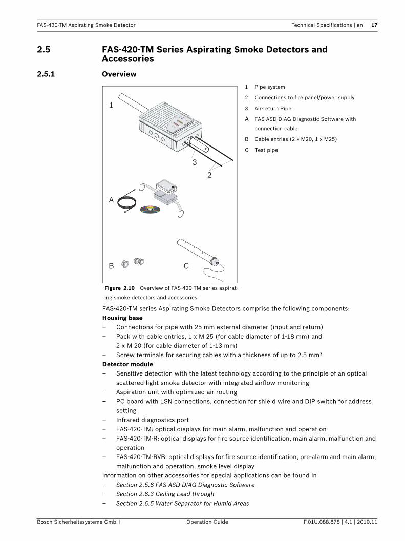
FAS-420-TM series Aspirating Smoke Detectors comprise the following components:Housing base– Connections for pipe with 25 mm external diameter (input and return)– Pack with cable entries, 1 x M 25 (for cable diameter of 1-18 mm) and
2 x M 20 (for cable diameter of 1-13 mm)– Screw terminals for securing cables with a thickness of up to 2.5 mm²Detector module– Sensitive detection with the latest technology according to the principle of an optical
scattered-light smoke detector with integrated airflow monitoring– Aspiration unit with optimized air routing– PC board with LSN connections, connection for shield wire and DIP switch for address
setting– Infrared diagnostics port– FAS-420-TM: optical displays for main alarm, malfunction and operation– FAS-420-TM-R: optical displays for fire source identification, main alarm, malfunction and
operation– FAS-420-TM-RVB: optical displays for fire source identification, pre-alarm and main alarm,
malfunction and operation, smoke level displayInformation on other accessories for special applications can be found in– Section 2.5.6 FAS-ASD-DIAG Diagnostic Software– Section 2.6.3 Ceiling Lead-through– Section 2.6.5 Water Separator for Humid Areas
Figure 2.10 Overview of FAS-420-TM series aspirat-
ing smoke detectors and accessories
1 Pipe system
2 Connections to fire panel/power supply
3 Air-return Pipe
A FAS-ASD-DIAG Diagnostic Software with
connection cable
B Cable entries (2 x M20, 1 x M25)
C Test pipe
1
2
3
A
B C
FAS-420-TM serie
s
18 en | Technical Specifications FAS-420-TM Aspirating Smoke Detector
F.01U.088.878 | 4.1 | 2010.11 Operation Guide Bosch Sicherheitssysteme GmbH
2.5.2 FAS-420-TM Series Connections
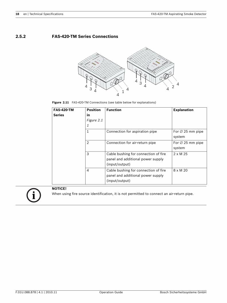
Figure 2.11 FAS-420-TM Connections (see table below for explanations)
FAS-420-TM Series
Position in Figure 2.11
Function Explanation
1 Connection for aspiration pipe For ∅ 25 mm pipe system
2 Connection for air-return pipe For ∅ 25 mm pipe system
3 Cable bushing for connection of fire panel and additional power supply (input/output)
2 x M 25
4 Cable bushing for connection of fire panel and additional power supply (input/output)
8 x M 20
FAS-420-TM serie
s
FAS-420-TM series
21
33
44
44
44 4
4
NOTICE! When using fire source identification, it is not permitted to connect an air-return pipe.
FAS-420-TM Aspirating Smoke Detector Technical Specifications | en 19
Bosch Sicherheitssysteme GmbH Operation Guide F.01U.088.878 | 4.1 | 2010.11
2.5.3 FAS-420-TM Displays
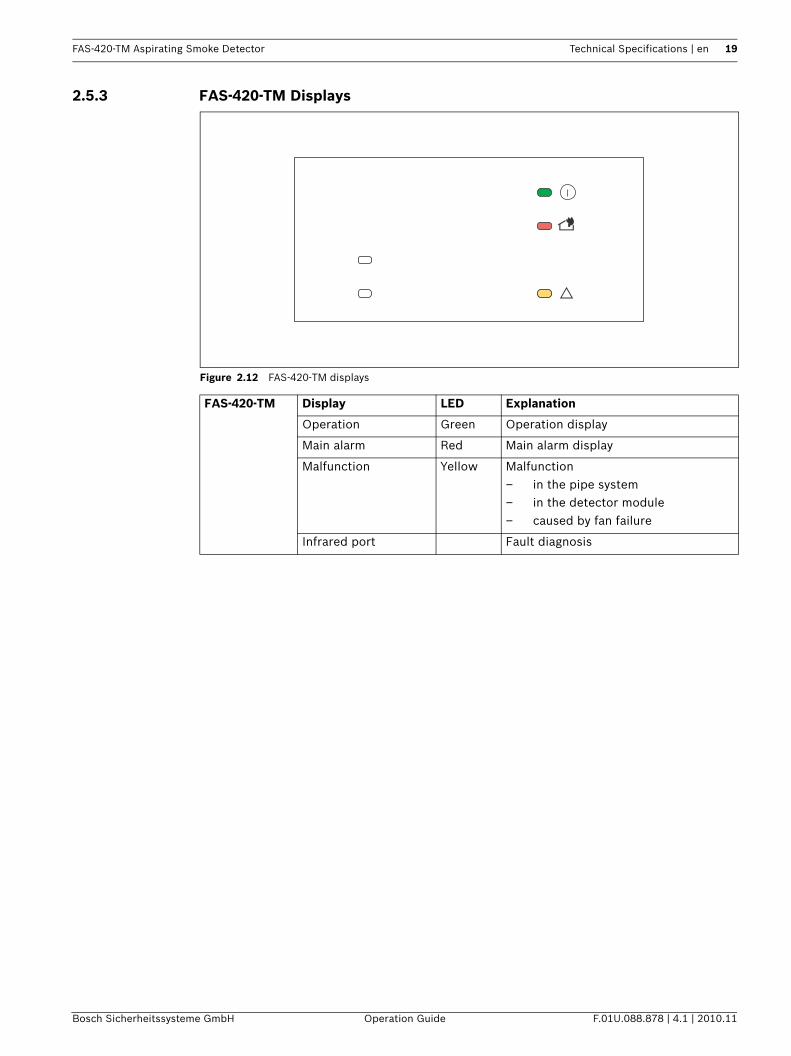
Figure 2.12 FAS-420-TM displays
FAS-420-TM Display LED Explanation
Operation Green Operation display
Main alarm Red Main alarm display
Malfunction Yellow Malfunction– in the pipe system– in the detector module– caused by fan failure
Infrared port Fault diagnosis
20 en | Technical Specifications FAS-420-TM Aspirating Smoke Detector
F.01U.088.878 | 4.1 | 2010.11 Operation Guide Bosch Sicherheitssysteme GmbH
2.5.4 FAS-420-TM-R Displays
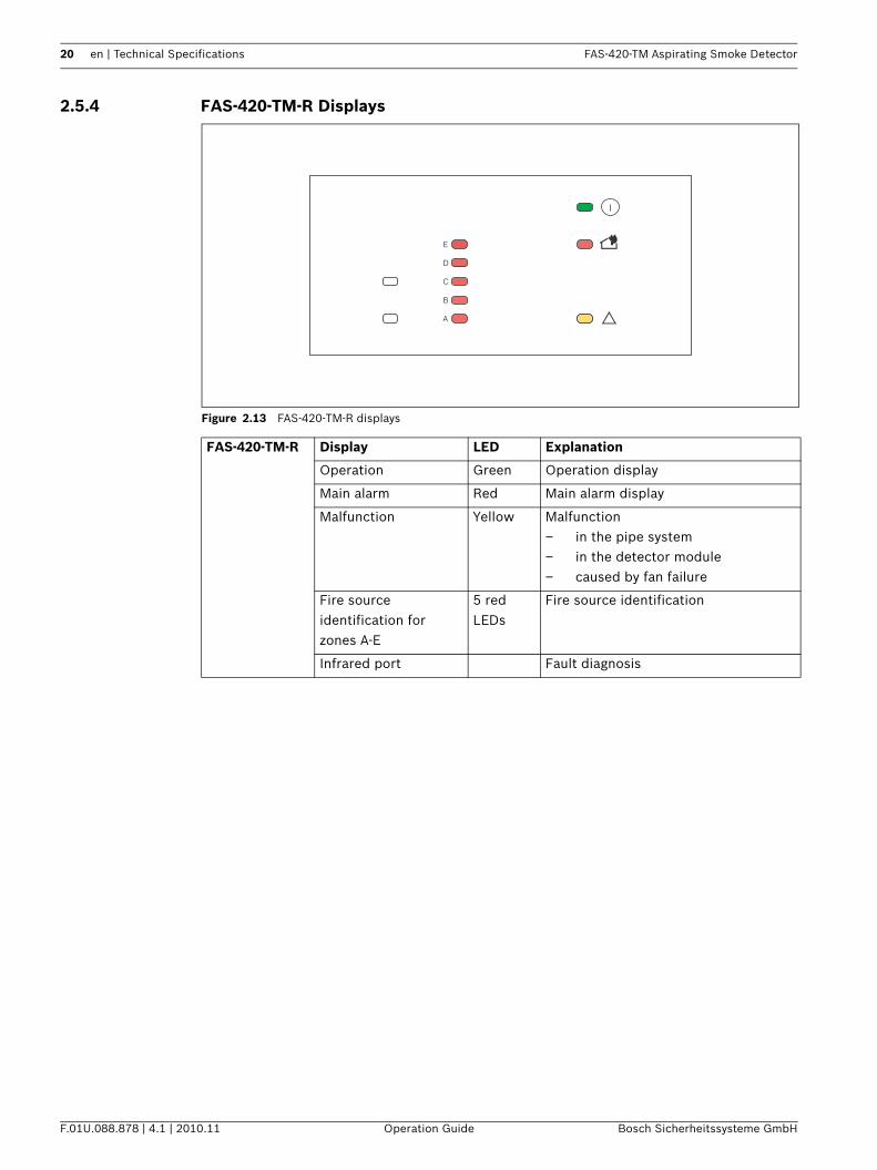
Figure 2.13 FAS-420-TM-R displays
FAS-420-TM-R Display LED Explanation
Operation Green Operation display
Main alarm Red Main alarm display
Malfunction Yellow Malfunction– in the pipe system– in the detector module– caused by fan failure
Fire source identification for zones A-E
5 red LEDs
Fire source identification
Infrared port Fault diagnosis
E
D
C
B
A
FAS-420-TM Aspirating Smoke Detector Technical Specifications | en 21
Bosch Sicherheitssysteme GmbH Operation Guide F.01U.088.878 | 4.1 | 2010.11
2.5.5 FAS-420-TM-RVB Displays
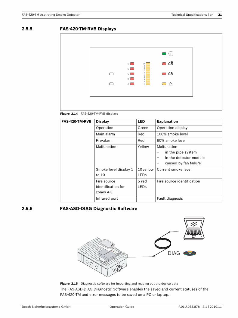
Figure 2.14 FAS-420-TM-RVB displays
2.5.6 FAS-ASD-DIAG Diagnostic Software
Figure 2.15 Diagnostic software for importing and reading out the device data
The FAS-ASD-DIAG Diagnostic Software enables the saved and current statuses of the FAS-420-TM and error messages to be saved on a PC or laptop.
FAS-420-TM-RVB Display LED Explanation
Operation Green Operation display
Main alarm Red 100% smoke level
Pre-alarm Red 60% smoke level
Malfunction Yellow Malfunction– in the pipe system– in the detector module– caused by fan failure
Smoke level display 1 to 10
10 yellow LEDs
Current smoke level
Fire source identification for zones A-E
5 red LEDs
Fire source identification
Infrared port Fault diagnosis
E
D
C
B
A
10987654321
FAS-
DIAG
22 en | Technical Specifications FAS-420-TM Aspirating Smoke Detector
F.01U.088.878 | 4.1 | 2010.11 Operation Guide Bosch Sicherheitssysteme GmbH
Data is transmitted to the diagnostic appliance via the infrared port of the aspirating smoke detector. The USB cable provided is used to transmit the data from the diagnostic appliance to the PC/laptop (see Figure 2.15).Windows 2000 or Windows XP can be used as the operating system. For correct color display, the monitor and graphics card must be able to display more than 256 colors.Diagnostic messages remain saved in the FAS-420-TM for at least 3 days in order to be able to evaluate even short, sporadically occurring errors (e.g. in case of changed operating conditions). Resetting the FAS-420-TM via the diagnostic software deletes all saved diagnostic messages. The software also allows the deletion of error messages.
2.5.7 Remote IndicatorsA remote indicator must be connected if the aspirating smoke detector is not directly visible or has been mounted in false ceilings or floors.The external detector alarm display is installed in an obvious place in halls or entrances of the building section or areas concerned.FNS-420-R LSN Strobes can be used as remote indicators. These must be ordered separately.The FNS-420-R LSN strobes can be addressed and are connected to the LSN bus.If the FAS-420-TM-R and FAS-420-TM-RVB device variants with fire source identification are used, the FNS-420-R LSN Strobes can be assigned to the various monitoring ranges and, in the event of a fire, the location of the fire can be identified.
2.6 Pipe System Components
2.6.1 Overview
NOTICE! The diagnostic software can be used to save in file format all stored and current diagnostics data and any settings made via the fire panel programming software. To be able to compare the data read out, save each file under a different file name.
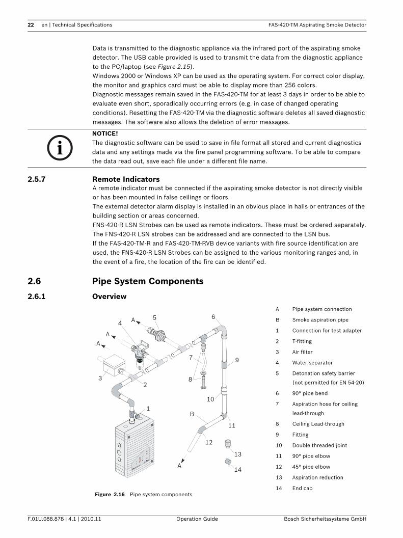
Figure 2.16 Pipe system components
A Pipe system connection
B Smoke aspiration pipe
1 Connection for test adapter
2 T-fitting
3 Air filter
4 Water separator
5 Detonation safety barrier
(not permitted for EN 54-20)
6 90° pipe bend
7 Aspiration hose for ceiling
lead-through
8 Ceiling Lead-through
9 Fitting
10 Double threaded joint
11 90° pipe elbow
12 45° pipe elbow
13 Aspiration reduction
14 End cap
FAS-420-TM serie
s
AA
A
45
32
7
6
8
9
10
11
12
13
1
14
A
B
FAS-420-TM Aspirating Smoke Detector Technical Specifications | en 23
Bosch Sicherheitssysteme GmbH Operation Guide F.01U.088.878 | 4.1 | 2010.11
During planning/design, a distinction is drawn between area monitoring and equipment monitoring. For both applications, PVC pipes and halogen-free pipes can be used. The pipes used for equipment monitoring should be halogen-free.Figure 2.16 shows essential accessory components that can be selected for the application concerned.The pipe system must be constructed using pipes with an external diameter of 25 mm and the associated fittings.
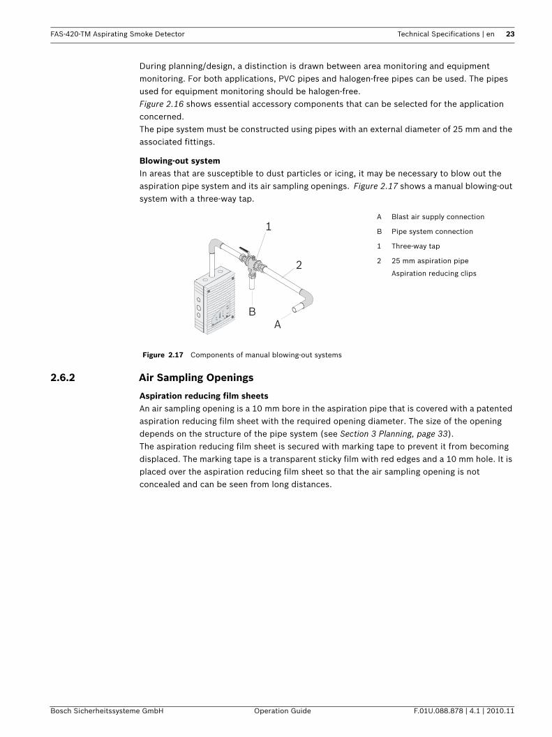
Blowing-out systemIn areas that are susceptible to dust particles or icing, it may be necessary to blow out the aspiration pipe system and its air sampling openings. Figure 2.17 shows a manual blowing-out system with a three-way tap.
2.6.2 Air Sampling Openings
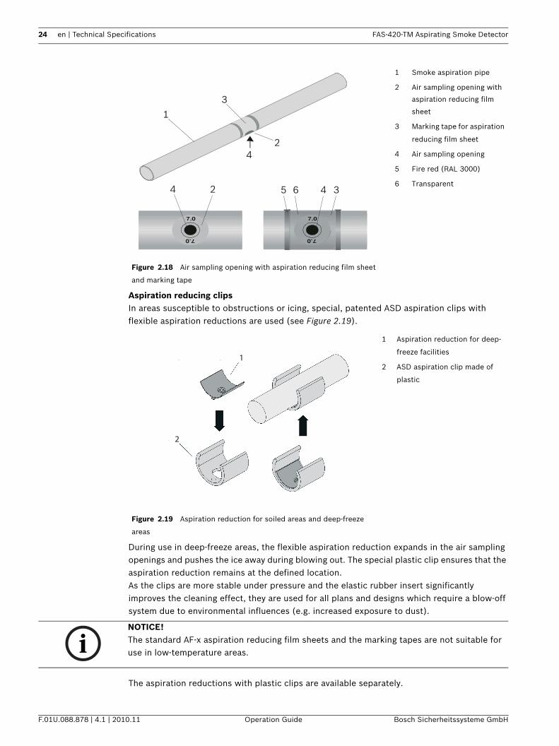
Aspiration reducing film sheetsAn air sampling opening is a 10 mm bore in the aspiration pipe that is covered with a patented aspiration reducing film sheet with the required opening diameter. The size of the opening depends on the structure of the pipe system (see Section 3 Planning, page 33).The aspiration reducing film sheet is secured with marking tape to prevent it from becoming displaced. The marking tape is a transparent sticky film with red edges and a 10 mm hole. It is placed over the aspiration reducing film sheet so that the air sampling opening is not concealed and can be seen from long distances.
Figure 2.17 Components of manual blowing-out systems
A Blast air supply connection
B Pipe system connection
1 Three-way tap
2 25 mm aspiration pipe
Aspiration reducing clips
FAS-420-TM serie
s
A
1
2
B
24 en | Technical Specifications FAS-420-TM Aspirating Smoke Detector
F.01U.088.878 | 4.1 | 2010.11 Operation Guide Bosch Sicherheitssysteme GmbH
Aspiration reducing clipsIn areas susceptible to obstructions or icing, special, patented ASD aspiration clips with flexible aspiration reductions are used (see Figure 2.19).
During use in deep-freeze areas, the flexible aspiration reduction expands in the air sampling openings and pushes the ice away during blowing out. The special plastic clip ensures that the aspiration reduction remains at the defined location.As the clips are more stable under pressure and the elastic rubber insert significantly improves the cleaning effect, they are used for all plans and designs which require a blow-off system due to environmental influences (e.g. increased exposure to dust).
The aspiration reductions with plastic clips are available separately.
Figure 2.18 Air sampling opening with aspiration reducing film sheet
and marking tape
1 Smoke aspiration pipe
2 Air sampling opening with
aspiration reducing film
sheet
3 Marking tape for aspiration
reducing film sheet
4 Air sampling opening
5 Fire red (RAL 3000)
6 Transparent
Figure 2.19 Aspiration reduction for soiled areas and deep-freeze
areas
1 Aspiration reduction for deep-
freeze facilities
2 ASD aspiration clip made of
plastic
1
3
36
2
4
4
452
1
2
NOTICE! The standard AF-x aspiration reducing film sheets and the marking tapes are not suitable for use in low-temperature areas.
FAS-420-TM Aspirating Smoke Detector Technical Specifications | en 25
Bosch Sicherheitssysteme GmbH Operation Guide F.01U.088.878 | 4.1 | 2010.11
2.6.3 Ceiling Lead-through
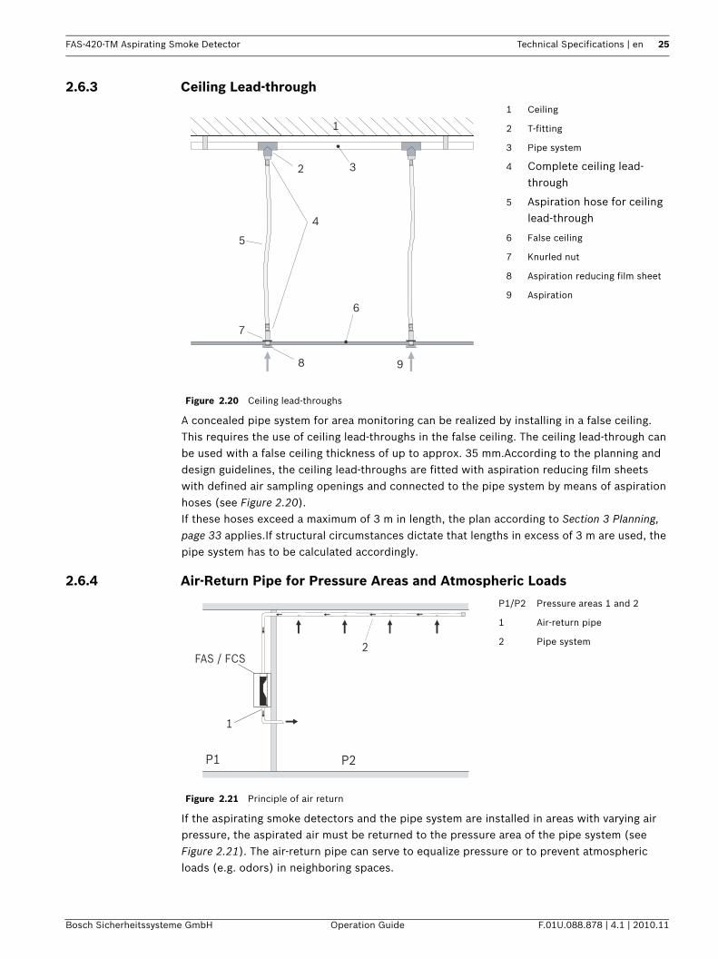
A concealed pipe system for area monitoring can be realized by installing in a false ceiling. This requires the use of ceiling lead-throughs in the false ceiling. The ceiling lead-through can be used with a false ceiling thickness of up to approx. 35 mm.According to the planning and design guidelines, the ceiling lead-throughs are fitted with aspiration reducing film sheets with defined air sampling openings and connected to the pipe system by means of aspiration hoses (see Figure 2.20).If these hoses exceed a maximum of 3 m in length, the plan according to Section 3 Planning, page 33 applies.If structural circumstances dictate that lengths in excess of 3 m are used, the pipe system has to be calculated accordingly.
2.6.4 Air-Return Pipe for Pressure Areas and Atmospheric Loads
If the aspirating smoke detectors and the pipe system are installed in areas with varying air pressure, the aspirated air must be returned to the pressure area of the pipe system (see Figure 2.21). The air-return pipe can serve to equalize pressure or to prevent atmospheric loads (e.g. odors) in neighboring spaces.
Figure 2.20 Ceiling lead-throughs
1 Ceiling
2 T-fitting
3 Pipe system
4 Complete ceiling lead-through
5 Aspiration hose for ceiling lead-through
6 False ceiling
7 Knurled nut
8 Aspiration reducing film sheet
9 Aspiration
1
2 3
4
6
7
8 9
5
Figure 2.21 Principle of air return
P1/P2 Pressure areas 1 and 2
1 Air-return pipe
2 Pipe system2FAS / FCS
1
P1 P2
26 en | Technical Specifications FAS-420-TM Aspirating Smoke Detector
F.01U.088.878 | 4.1 | 2010.11 Operation Guide Bosch Sicherheitssysteme GmbH
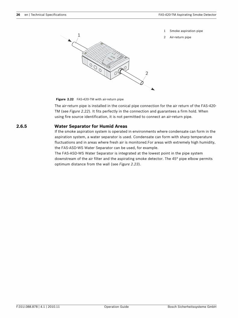
The air-return pipe is installed in the conical pipe connection for the air return of the FAS-420-TM (see Figure 2.22). It fits perfectly in the connection and guarantees a firm hold. When using fire source identification, it is not permitted to connect an air-return pipe.
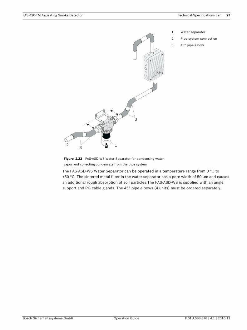
2.6.5 Water Separator for Humid AreasIf the smoke aspiration system is operated in environments where condensate can form in the aspiration system, a water separator is used. Condensate can form with sharp temperature fluctuations and in areas where fresh air is monitored.For areas with extremely high humidity, the FAS-ASD-WS Water Separator can be used, for example.The FAS-ASD-WS Water Separator is integrated at the lowest point in the pipe system downstream of the air filter and the aspirating smoke detector. The 45° pipe elbow permits optimum distance from the wall (see Figure 2.23).
Figure 2.22 FAS-420-TM with air-return pipe
1 Smoke aspiration pipe
2 Air-return pipe
FAS-420-TM serie
s
2
1
FAS-420-TM Aspirating Smoke Detector Technical Specifications | en 27
Bosch Sicherheitssysteme GmbH Operation Guide F.01U.088.878 | 4.1 | 2010.11
The FAS-ASD-WS Water Separator can be operated in a temperature range from 0 °C to +50 °C. The sintered metal filter in the water separator has a pore width of 50 µm and causes an additional rough absorption of soil particles.The FAS-ASD-WS is supplied with an angle support and PG cable glands. The 45° pipe elbows (4 units) must be ordered separately.
Figure 2.23 FAS-ASD-WS Water Separator for condensing water
vapor and collecting condensate from the pipe system
1 Water separator
2 Pipe system connection
3 45° pipe elbow
123
3
FAS-420-TM serie
s
28 en | Technical Specifications FAS-420-TM Aspirating Smoke Detector
F.01U.088.878 | 4.1 | 2010.11 Operation Guide Bosch Sicherheitssysteme GmbH
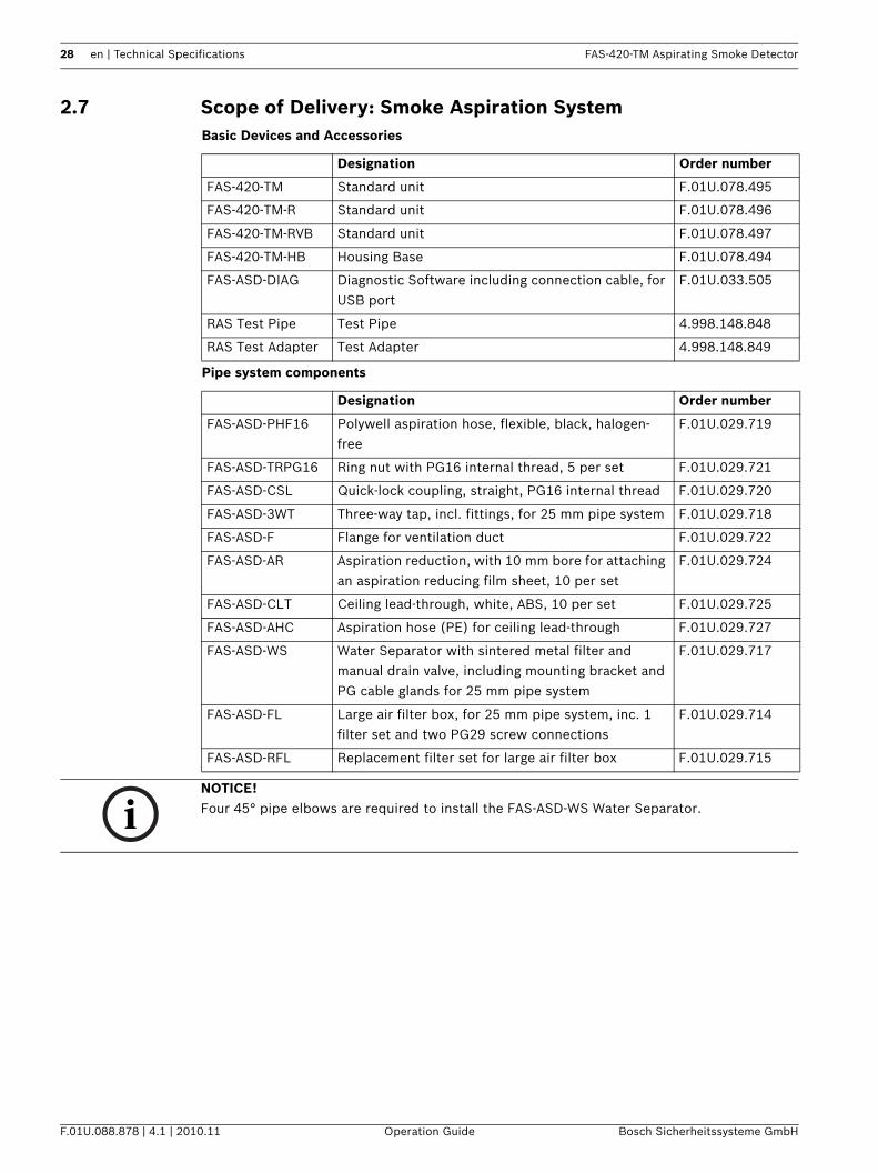
2.7 Scope of Delivery: Smoke Aspiration SystemBasic Devices and Accessories
Pipe system components
Designation Order number
FAS-420-TM Standard unit F.01U.078.495
FAS-420-TM-R Standard unit F.01U.078.496
FAS-420-TM-RVB Standard unit F.01U.078.497
FAS-420-TM-HB Housing Base F.01U.078.494
FAS-ASD-DIAG Diagnostic Software including connection cable, for USB port
F.01U.033.505
RAS Test Pipe Test Pipe 4.998.148.848
RAS Test Adapter Test Adapter 4.998.148.849
Designation Order number
FAS-ASD-PHF16 Polywell aspiration hose, flexible, black, halogen-free
F.01U.029.719
FAS-ASD-TRPG16 Ring nut with PG16 internal thread, 5 per set F.01U.029.721
FAS-ASD-CSL Quick-lock coupling, straight, PG16 internal thread F.01U.029.720
FAS-ASD-3WT Three-way tap, incl. fittings, for 25 mm pipe system F.01U.029.718
FAS-ASD-F Flange for ventilation duct F.01U.029.722
FAS-ASD-AR Aspiration reduction, with 10 mm bore for attaching an aspiration reducing film sheet, 10 per set
F.01U.029.724
FAS-ASD-CLT Ceiling lead-through, white, ABS, 10 per set F.01U.029.725
FAS-ASD-AHC Aspiration hose (PE) for ceiling lead-through F.01U.029.727
FAS-ASD-WS Water Separator with sintered metal filter and manual drain valve, including mounting bracket and PG cable glands for 25 mm pipe system
F.01U.029.717
FAS-ASD-FL Large air filter box, for 25 mm pipe system, inc. 1 filter set and two PG29 screw connections
F.01U.029.714
FAS-ASD-RFL Replacement filter set for large air filter box F.01U.029.715
NOTICE! Four 45° pipe elbows are required to install the FAS-ASD-WS Water Separator.
FAS-420-TM Aspirating Smoke Detector Technical Specifications | en 29
Bosch Sicherheitssysteme GmbH Operation Guide F.01U.088.878 | 4.1 | 2010.11
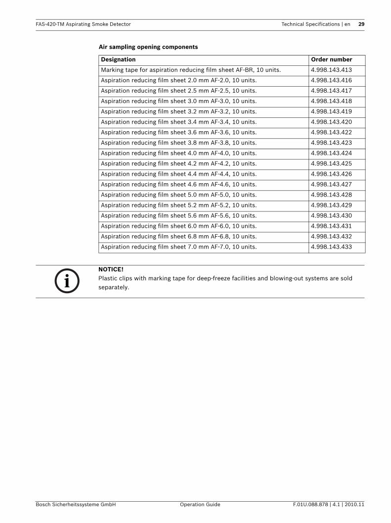
Air sampling opening components
Designation Order number
Marking tape for aspiration reducing film sheet AF-BR, 10 units. 4.998.143.413
Aspiration reducing film sheet 2.0 mm AF-2.0, 10 units. 4.998.143.416
Aspiration reducing film sheet 2.5 mm AF-2.5, 10 units. 4.998.143.417
Aspiration reducing film sheet 3.0 mm AF-3.0, 10 units. 4.998.143.418
Aspiration reducing film sheet 3.2 mm AF-3.2, 10 units. 4.998.143.419
Aspiration reducing film sheet 3.4 mm AF-3.4, 10 units. 4.998.143.420
Aspiration reducing film sheet 3.6 mm AF-3.6, 10 units. 4.998.143.422
Aspiration reducing film sheet 3.8 mm AF-3.8, 10 units. 4.998.143.423
Aspiration reducing film sheet 4.0 mm AF-4.0, 10 units. 4.998.143.424
Aspiration reducing film sheet 4.2 mm AF-4.2, 10 units. 4.998.143.425
Aspiration reducing film sheet 4.4 mm AF-4.4, 10 units. 4.998.143.426
Aspiration reducing film sheet 4.6 mm AF-4.6, 10 units. 4.998.143.427
Aspiration reducing film sheet 5.0 mm AF-5.0, 10 units. 4.998.143.428
Aspiration reducing film sheet 5.2 mm AF-5.2, 10 units. 4.998.143.429
Aspiration reducing film sheet 5.6 mm AF-5.6, 10 units. 4.998.143.430
Aspiration reducing film sheet 6.0 mm AF-6.0, 10 units. 4.998.143.431
Aspiration reducing film sheet 6.8 mm AF-6.8, 10 units. 4.998.143.432
Aspiration reducing film sheet 7.0 mm AF-7.0, 10 units. 4.998.143.433
NOTICE! Plastic clips with marking tape for deep-freeze facilities and blowing-out systems are sold separately.
30 en | Technical Specifications FAS-420-TM Aspirating Smoke Detector
F.01U.088.878 | 4.1 | 2010.11 Operation Guide Bosch Sicherheitssysteme GmbH
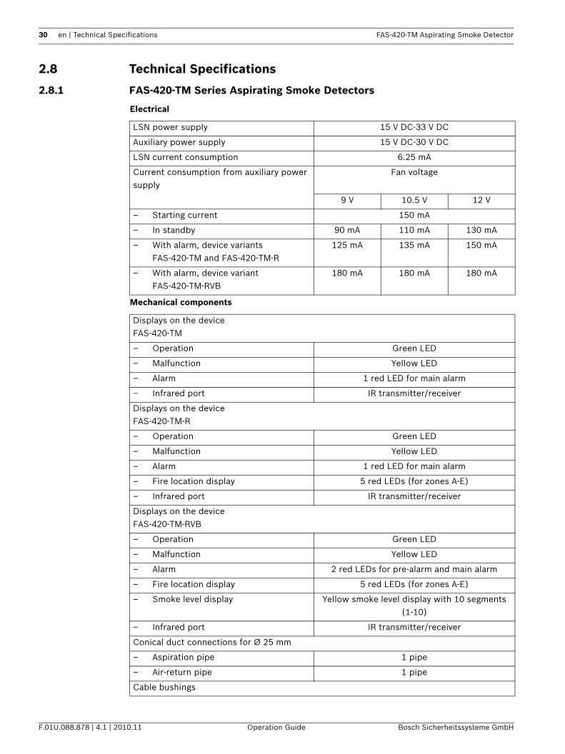
2.8 Technical Specifications
2.8.1 FAS-420-TM Series Aspirating Smoke Detectors
Electrical
Mechanical components
LSN power supply 15 V DC-33 V DC
Auxiliary power supply 15 V DC-30 V DC
LSN current consumption 6.25 mA
Current consumption from auxiliary power supply
Fan voltage
9 V 10.5 V 12 V
– Starting current 150 mA
– In standby 90 mA 110 mA 130 mA
– With alarm, device variants FAS-420-TM and FAS-420-TM-R
125 mA 135 mA 150 mA
– With alarm, device variant FAS-420-TM-RVB
180 mA 180 mA 180 mA
Displays on the deviceFAS-420-TM
– Operation Green LED
– Malfunction Yellow LED
– Alarm 1 red LED for main alarm
– Infrared port IR transmitter/receiver
Displays on the deviceFAS-420-TM-R
– Operation Green LED
– Malfunction Yellow LED
– Alarm 1 red LED for main alarm
– Fire location display 5 red LEDs (for zones A-E)
– Infrared port IR transmitter/receiver
Displays on the deviceFAS-420-TM-RVB
– Operation Green LED
– Malfunction Yellow LED
– Alarm 2 red LEDs for pre-alarm and main alarm
– Fire location display 5 red LEDs (for zones A-E)
– Smoke level display Yellow smoke level display with 10 segments (1-10)
– Infrared port IR transmitter/receiver
Conical duct connections for Ø 25 mm
– Aspiration pipe 1 pipe
– Air-return pipe 1 pipe
Cable bushings
FAS-420-TM Aspirating Smoke Detector Technical Specifications | en 31
Bosch Sicherheitssysteme GmbH Operation Guide F.01U.088.878 | 4.1 | 2010.11
Environmental conditions
Special features
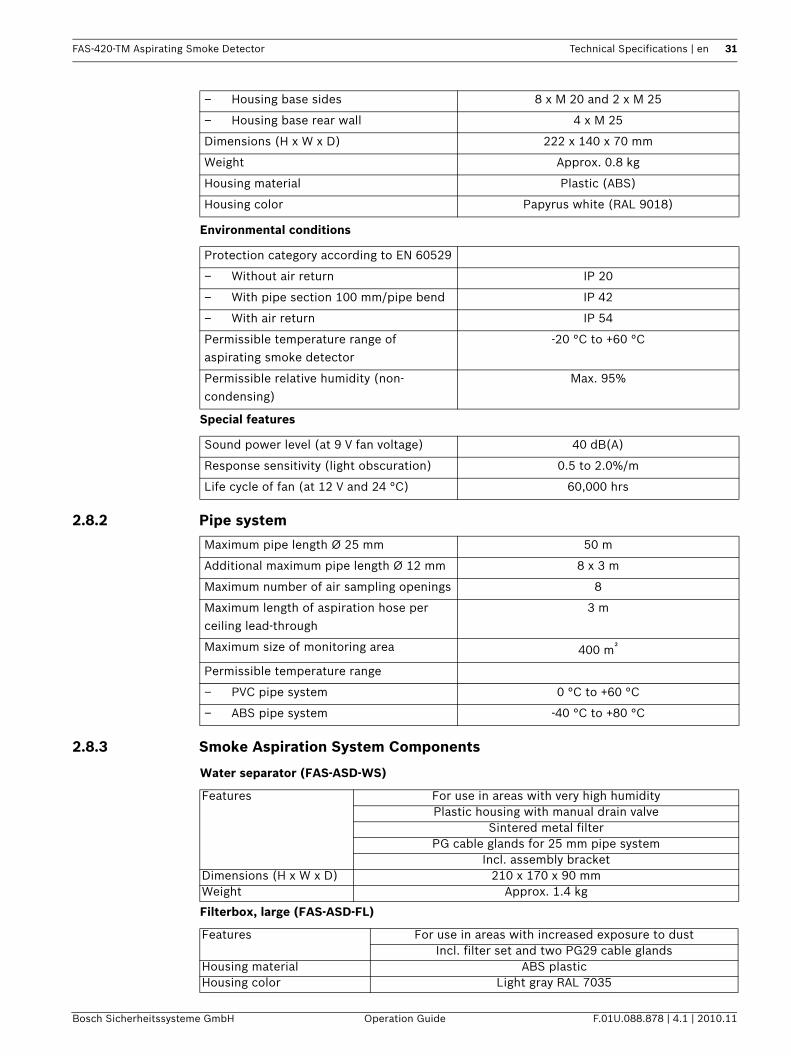
2.8.2 Pipe system
2.8.3 Smoke Aspiration System Components
Water separator (FAS-ASD-WS)
Filterbox, large (FAS-ASD-FL)
– Housing base sides 8 x M 20 and 2 x M 25
– Housing base rear wall 4 x M 25
Dimensions (H x W x D) 222 x 140 x 70 mm
Weight Approx. 0.8 kg
Housing material Plastic (ABS)
Housing color Papyrus white (RAL 9018)
Protection category according to EN 60529
– Without air return IP 20
– With pipe section 100 mm/pipe bend IP 42
– With air return IP 54
Permissible temperature range of aspirating smoke detector
-20 °C to +60 °C
Permissible relative humidity (non-condensing)
Max. 95%
Sound power level (at 9 V fan voltage) 40 dB(A)
Response sensitivity (light obscuration) 0.5 to 2.0%/m
Life cycle of fan (at 12 V and 24 °C) 60,000 hrs
Maximum pipe length Ø 25 mm 50 m
Additional maximum pipe length Ø 12 mm 8 x 3 m
Maximum number of air sampling openings 8
Maximum length of aspiration hose per ceiling lead-through
3 m
Maximum size of monitoring area 400 m²
Permissible temperature range
– PVC pipe system 0 °C to +60 °C
– ABS pipe system -40 °C to +80 °C
Features For use in areas with very high humidityPlastic housing with manual drain valve
Sintered metal filterPG cable glands for 25 mm pipe system
Incl. assembly bracketDimensions (H x W x D) 210 x 170 x 90 mmWeight Approx. 1.4 kg
Features For use in areas with increased exposure to dustIncl. filter set and two PG29 cable glands
Housing material ABS plasticHousing color Light gray RAL 7035
32 en | Technical Specifications FAS-420-TM Aspirating Smoke Detector
F.01U.088.878 | 4.1 | 2010.11 Operation Guide Bosch Sicherheitssysteme GmbH
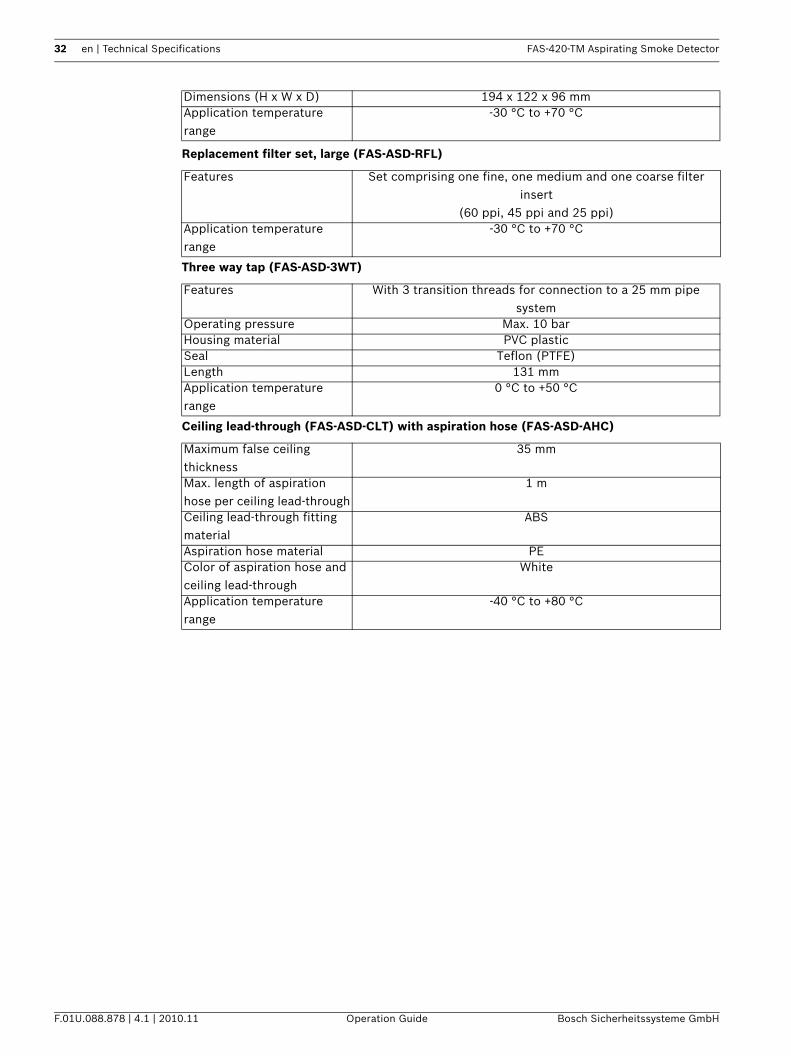
Replacement filter set, large (FAS-ASD-RFL)
Three way tap (FAS-ASD-3WT)
Ceiling lead-through (FAS-ASD-CLT) with aspiration hose (FAS-ASD-AHC)
Dimensions (H x W x D) 194 x 122 x 96 mmApplication temperature range
-30 °C to +70 °C
Features Set comprising one fine, one medium and one coarse filter insert
(60 ppi, 45 ppi and 25 ppi)Application temperature range
-30 °C to +70 °C
Features With 3 transition threads for connection to a 25 mm pipe system
Operating pressure Max. 10 barHousing material PVC plasticSeal Teflon (PTFE)Length 131 mmApplication temperature range
0 °C to +50 °C
Maximum false ceiling thickness
35 mm
Max. length of aspiration hose per ceiling lead-through
1 m
Ceiling lead-through fitting material
ABS
Aspiration hose material PEColor of aspiration hose and ceiling lead-through
White
Application temperature range
-40 °C to +80 °C
FAS-420-TM Aspirating Smoke Detector Planning | en 33
Bosch Sicherheitssysteme GmbH Operation Guide F.01U.088.878 | 4.1 | 2010.11
3 Planning
3.1 RegulationsThe planning regulation below is based on the system limits of the FAS-420-TM series. Here, the corresponding national regulations of the countries in their respectively applicable version must be adhered to and planning must be adjusted to these.The planning for the aspirating smoke detector in accordance with EN 54-20 is described below. The basic conditions are specified in Section 3.1 Regulations. Planning must be carried out in accordance with Section 3.6 Standard Pipe Planning. In addition to 3.6 , special applications are also bound by the restrictions of the planning notes in accordance with Section 3.7 Planning with Single-hole Monitoring and the following sections. These must be taken into account from the start in the case of any special planning processes.Planning options in accordance with EN 54-20:Various technical solutions are available to suit different planning criteria. The following table lists the chapters in which the solutions are described.
With regard to the planning regulation below, the applicable national regulations of the countries concerned must be observed and the plans modified accordingly.EN 54-20For VdS systems, compliance is also required with the following guidelines:– "Guideline for automatic fire detection systems, planning and installation", VdS
Schadenverhütung GmbH, Cologne (VdS 2095)– The guideline "Installation protection for electrical and electronic systems" VdS
Schadenverhütung GmbH, Cologne (VdS 2304)– The "Planning Aspirating Fire Detectors" data sheet from VdS Schadenverhütung GmbH,
Cologne (VdS 3435)The applicable national regulations must also be observed, for example in Germany:– DIN VDE 0833 parts 1 and 2 "Alarm systems for fire, intrusion and hold-up"– Additional provisions for the installation of fire detection systems, which are published
by fire directors of fire departments, by the construction supervision authorities or by the construction law authorities that have only local validity.
Planning criteria Technical solution Principles Restriction
Area monitoring in general
Basic planning 3.6
Detection of failure of a single opening
Single-hole monitoring planning
3.6 3.7
Equipment protection/cabinet monitoring
Simplified pipe planning 3.6 3.8
Ventilation ducts Planning for forced airflow 3.6 3.9
NOTICE! – For planning, the system limits in accordance with Section 3.5 Planning Limits are to be
observed.– Select airflow monitoring and the associated planning limits (see Section 3.3 Airflow
Monitoring) and check these for any restrictions imposed by country-specific regulations.– If the on-site planning deviates from the standard plans described below, this must
always be checked with activation attempts for correct detection of a malfunction and a fire. A special plan may be required.
– Plans not contained in the operation guide must be requested.
34 en | Planning FAS-420-TM Aspirating Smoke Detector
F.01U.088.878 | 4.1 | 2010.11 Operation Guide Bosch Sicherheitssysteme GmbH
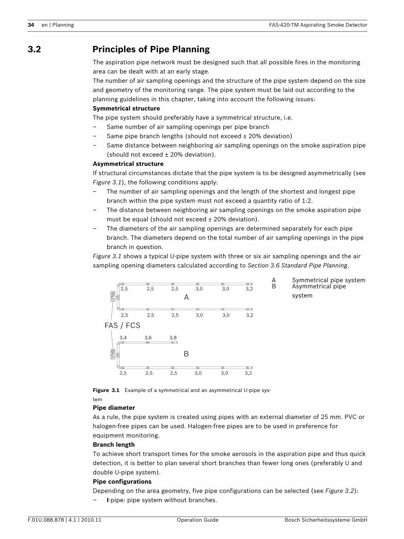
3.2 Principles of Pipe PlanningThe aspiration pipe network must be designed such that all possible fires in the monitoring area can be dealt with at an early stage.The number of air sampling openings and the structure of the pipe system depend on the size and geometry of the monitoring range. The pipe system must be laid out according to the planning guidelines in this chapter, taking into account the following issues:Symmetrical structureThe pipe system should preferably have a symmetrical structure, i.e.– Same number of air sampling openings per pipe branch– Same pipe branch lengths (should not exceed ± 20% deviation)– Same distance between neighboring air sampling openings on the smoke aspiration pipe
(should not exceed ± 20% deviation).Asymmetrical structureIf structural circumstances dictate that the pipe system is to be designed asymmetrically (see Figure 3.1), the following conditions apply:– The number of air sampling openings and the length of the shortest and longest pipe
branch within the pipe system must not exceed a quantity ratio of 1:2.– The distance between neighboring air sampling openings on the smoke aspiration pipe
must be equal (should not exceed ± 20% deviation).– The diameters of the air sampling openings are determined separately for each pipe
branch. The diameters depend on the total number of air sampling openings in the pipe branch in question.
Figure 3.1 shows a typical U-pipe system with three or six air sampling openings and the air sampling opening diameters calculated according to Section 3.6 Standard Pipe Planning.
Pipe diameterAs a rule, the pipe system is created using pipes with an external diameter of 25 mm. PVC or halogen-free pipes can be used. Halogen-free pipes are to be used in preference for equipment monitoring.Branch lengthTo achieve short transport times for the smoke aerosols in the aspiration pipe and thus quick detection, it is better to plan several short branches than fewer long ones (preferably U and double U-pipe system).Pipe configurationsDepending on the area geometry, five pipe configurations can be selected (see Figure 3.2):– I-pipe: pipe system without branches.
Figure 3.1 Example of a symmetrical and an asymmetrical U-pipe sys-
tem
A Symmetrical pipe systemB Asymmetrical pipe
systemA
B
FAS / FCS
2,5
3,4 3,6 3,8
3,02,5 2,5 3,23,0
2,5 3,02,5 2,5 3,23,0
2,5 3,02,5 2,5 3,23,0
FAS-420-TM Aspirating Smoke Detector Planning | en 35
Bosch Sicherheitssysteme GmbH Operation Guide F.01U.088.878 | 4.1 | 2010.11
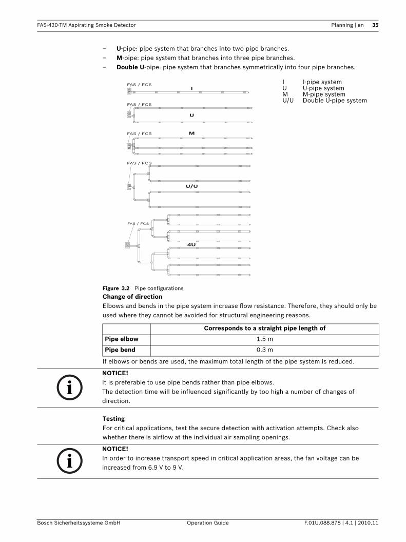
– U-pipe: pipe system that branches into two pipe branches.– M-pipe: pipe system that branches into three pipe branches.– Double U-pipe: pipe system that branches symmetrically into four pipe branches.
Change of directionElbows and bends in the pipe system increase flow resistance. Therefore, they should only be used where they cannot be avoided for structural engineering reasons.
If elbows or bends are used, the maximum total length of the pipe system is reduced.
TestingFor critical applications, test the secure detection with activation attempts. Check also whether there is airflow at the individual air sampling openings.
Figure 3.2 Pipe configurations
I I-pipe systemU U-pipe systemM M-pipe systemU/U Double U-pipe system
Corresponds to a straight pipe length of
Pipe elbow 1.5 m
Pipe bend 0.3 m
IFAS / FCS
FAS / FCS
FAS / FCS
U
U/U
FAS / FCS M
FAS / FCS
4U
NOTICE! It is preferable to use pipe bends rather than pipe elbows.The detection time will be influenced significantly by too high a number of changes of direction.
NOTICE! In order to increase transport speed in critical application areas, the fan voltage can be increased from 6.9 V to 9 V.
36 en | Planning FAS-420-TM Aspirating Smoke Detector
F.01U.088.878 | 4.1 | 2010.11 Operation Guide Bosch Sicherheitssysteme GmbH
3.3 Airflow MonitoringEN 54-20 requires the detection of a 20-percent change in the airflow volume by the detector module's airflow sensor. In order to achieve this, the activation threshold of the airflow sensor must be set to less than or equal to 20%. It is recommended that airflow calibration is carried out dependent on air pressure for both of these settings. In systems that do not need to comply with EN 54-20, any threshold can be set. The airflow monitoring of the smoke aspiration pipes is planned taking into account the applicable national regulations for the country concerned.Adapting the airflow sensitivityThe sensitivity of the airflow sensor must be adapted to the application. Breakages and obstructions must be accurately detected in the event of a malfunction.The trigger threshold, and thus the sensitivity of the airflow sensor, can be set from 10 to 50%.
Dynamic airflow sensorsThe airflow monitoring of the unit makes it possible to detect breaks at the end of pipes and identify sudden obstruction of individual air sampling openings (e.g. following tampering with the pipe system). If the dynamic airflow sensors were activated via the diagnostic software, note the following restrictions.RestrictionsAirflow monitoring may only be set to level I if – planning was carried out in accordance with "single-hole monitoring" (see
Section 3.7 Planning with Single-hole Monitoring, page 44), – the airflow sensor was calibrated dependent on air pressure (Section 6.3.2 Air-Pressure-
Dependent Calibration, page 77) – and no larger airflow fluctuations can occur.Air pressure differencesThere must be equal air pressure along the length of the aspiration pipe.
Complies with EN 54-20
Activation threshold 10% 20% 40% 50%
Sensitivity Very high High Average Low
NOTICE! Selection of the largest possible, precisely still-approved level is recommended.
NOTICE! If the aspirating smoke detectors and the pipe system are positioned in areas with different air pressures, the air aspirated by the FAS-420 must be returned to the pressure area of the pipe system (see Section 2.6.4 Air-Return Pipe for Pressure Areas and Atmospheric Loads, page 25).
NOTICE! FAS-420-TM series detectors with active fire source identification must be installed outside the areas to be monitored and without an air-return pipe.
FAS-420-TM Aspirating Smoke Detector Planning | en 37
Bosch Sicherheitssysteme GmbH Operation Guide F.01U.088.878 | 4.1 | 2010.11
3.4 Defining the Response SensitivityThe sensitivity of smoke aspiration systems can be divided into certain fire sensitivity classes in accordance with EN 54-20. These fire sensitivity classes describe specific examples of ways in which the systems can be applied. The permissible system plans given in 3.6 can be determined for each classification.Smoke aspiration systems with a higher fire sensitivity class according to EN 54-20 also satisfy the requirements of the lower classes.
The table shows the sensitivities you can choose from
The planning of the monitoring area always occurs according to the national guidelines for point-type smoke detectors.
NOTICE! As an air-return pipe needs to be provided when the FAS-420-TM series is used in areas with varying air pressures, and given that no air-return pipe is possible with ROOM·IDENT, it is not possible to use the FAS-420-TM series with ROOM·IDENT in areas with varying or fluctuating air pressures.
Class Description Application example
A Aspirating smoke detector with extremely high sensitivity
Very early detection: significant smoke dilution through air conditioning in IT
areas
B Aspirating smoke detector with increased sensitivity
Early detection: significant time gains thanks to very
early fire detection (without air condition)
C Smoke aspiration system with normal sensitivity
Normal detection: fire detection with the advantages of
smoke aspiration systems
NOTICE! Depending on the number of air sampling openings, fire sensitivity classes A, B and C can all be achieved with the detector modules available.
Sensitivity Standard sensitivity FAS-ASD-DIAG settings intervals
Detector module 0.5 - 2%/m 0.5%/m 0.1 %/m
38 en | Planning FAS-420-TM Aspirating Smoke Detector
F.01U.088.878 | 4.1 | 2010.11 Operation Guide Bosch Sicherheitssysteme GmbH
3.5 Planning LimitsThe following limit values must always be observed for the FAS-420-TM series:
The maximum total monitoring area of the FAS-420-TM and the maximum total pipe length depend on the plan selected (see Section 3.6 Standard Pipe Planning).
Limiting values Maximum monitoring area per air sampling opening Corresponds to the maximum monitoring range for point detectors, in line with applicable national norms.
Maximum number of air sampling openings per pipe
system1
8
Maximum number of air sampling openings per pipe system with fire source identification
5
Maximum pipe length per pipe system2
– Pipe ∅ 25 mm 50 m
– Additional pipe ∅ 12 mm 8 x 3 m
Maximum total monitoring area per pipe system 400 m²
Minimum pipe length between 2 air sampling openings
0.1 m
Minimum pipe length between 2 air sampling openings with fire source identification
3 m
Minimum pipe length between 2 air sampling openings
10 m
1 Plans not contained in the operation guide must be requested2 Depending on the selected plan, some restricted values may apply
NOTICE! The planning limits specified in this operation guide may be restricted in line with country-specific regulations.
FAS-420-TM Aspirating Smoke Detector Planning | en 39
Bosch Sicherheitssysteme GmbH Operation Guide F.01U.088.878 | 4.1 | 2010.11
3.6 Standard Pipe PlanningIn order to plan in accordance with the EN 54-20 standard, certain factors must be known, such as the system sensitivity requirements, the number of air sampling openings and the accessories needed for the application concerned. These factors can be used to determine the appropriate standard-compliant construction of the pipe system using the following chapter and the planning table in the appendix.
3.6.1 Determining the Necessary AccessoriesAs accessory components, e.g. filters, have a particular effect on the dimensions of pipe planning, the appropriate accessory must be selected for the application concerned in advance. Retrofitting an accessory, e.g. a fine filter, is largely only possible if a certain reserve is planned in advance.The following components must be taken into account in this regard:– Air filter– Water separator– Three-way-tapSee 2.8.3
3.6.2 Pipe Planning with Pipe AccessoriesFor the purpose of pipe system planning, the following planning table is available for all selected pipe accessories.– Planning without air filter– Planning with FAS-ASD-FL air filter
NOTICE! In order to improve the detection quality of a smoke aspiration system, an area can be monitored with more detection points than required by national guidelines. However, to calculate the necessary sensitivity of an aspirating smoke detector, the number of aspiration points required by the standard must be used.
40 en | Planning FAS-420-TM Aspirating Smoke Detector
F.01U.088.878 | 4.1 | 2010.11 Operation Guide Bosch Sicherheitssysteme GmbH
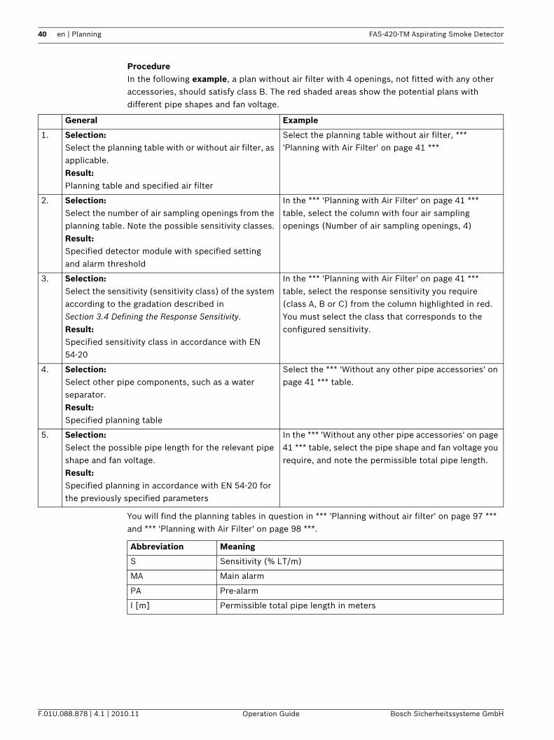
ProcedureIn the following example, a plan without air filter with 4 openings, not fitted with any other accessories, should satisfy class B. The red shaded areas show the potential plans with different pipe shapes and fan voltage.
You will find the planning tables in question in *** 'Planning without air filter' on page 97 *** and *** 'Planning with Air Filter' on page 98 ***.
General Example
1. Selection:Select the planning table with or without air filter, as applicable.Result:Planning table and specified air filter
Select the planning table without air filter, *** 'Planning with Air Filter' on page 41 ***
2. Selection:Select the number of air sampling openings from the planning table. Note the possible sensitivity classes.Result:Specified detector module with specified setting and alarm threshold
In the *** 'Planning with Air Filter' on page 41 *** table, select the column with four air sampling openings (Number of air sampling openings, 4)
3. Selection:Select the sensitivity (sensitivity class) of the system according to the gradation described in Section 3.4 Defining the Response Sensitivity.Result:Specified sensitivity class in accordance with EN 54-20
In the *** 'Planning with Air Filter' on page 41 *** table, select the response sensitivity you require (class A, B or C) from the column highlighted in red. You must select the class that corresponds to the configured sensitivity.
4. Selection:Select other pipe components, such as a water separator.Result:Specified planning table
Select the *** 'Without any other pipe accessories' on page 41 *** table.
5. Selection:Select the possible pipe length for the relevant pipe shape and fan voltage.Result:Specified planning in accordance with EN 54-20 for the previously specified parameters
In the *** 'Without any other pipe accessories' on page 41 *** table, select the pipe shape and fan voltage you require, and note the permissible total pipe length.
Abbreviation Meaning
S Sensitivity (% LT/m)
MA Main alarm
PA Pre-alarm
l [m] Permissible total pipe length in meters
FAS-420-TM Aspirating Smoke Detector Planning | en 41
Bosch Sicherheitssysteme GmbH Operation Guide F.01U.088.878 | 4.1 | 2010.11
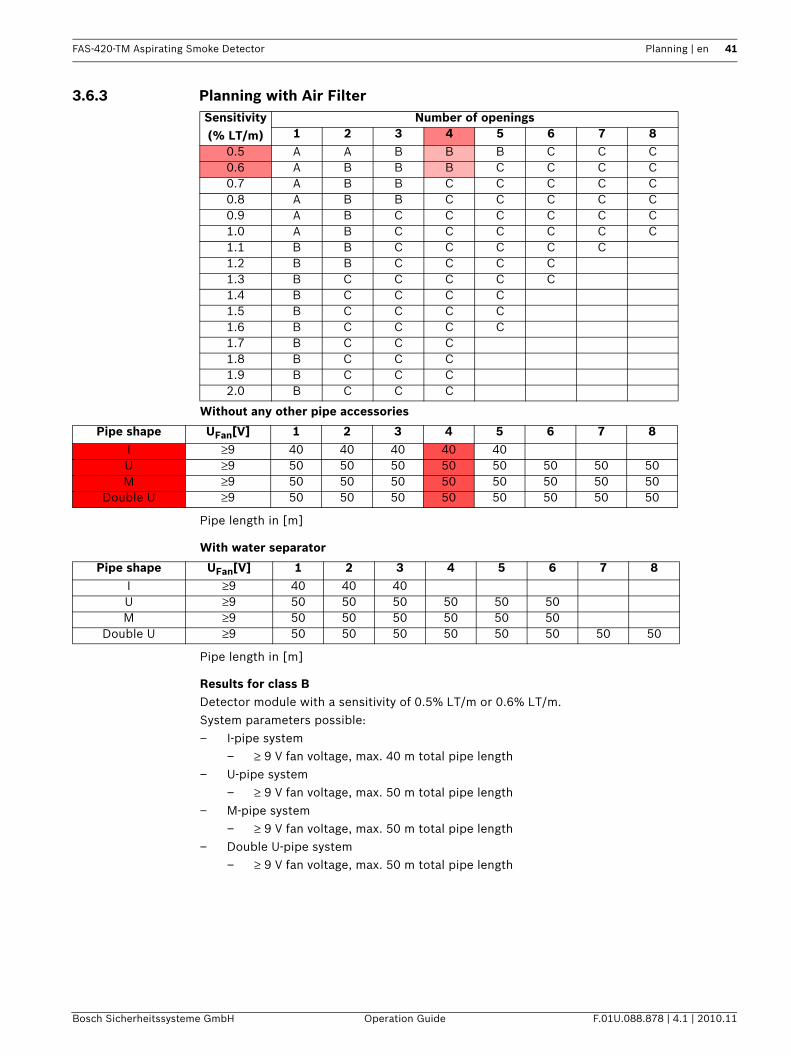
3.6.3 Planning with Air Filter
Without any other pipe accessories
Pipe length in [m]
With water separator
Pipe length in [m]
Results for class BDetector module with a sensitivity of 0.5% LT/m or 0.6% LT/m.System parameters possible:– I-pipe system
– ≥ 9 V fan voltage, max. 40 m total pipe length– U-pipe system
– ≥ 9 V fan voltage, max. 50 m total pipe length– M-pipe system
– ≥ 9 V fan voltage, max. 50 m total pipe length– Double U-pipe system
– ≥ 9 V fan voltage, max. 50 m total pipe length
Sensitivity (% LT/m)
Number of openings1 2 3 4 5 6 7 8
0.5 A A B B B C C C0.6 A B B B C C C C0.7 A B B C C C C C0.8 A B B C C C C C0.9 A B C C C C C C1.0 A B C C C C C C1.1 B B C C C C C1.2 B B C C C C1.3 B C C C C C1.4 B C C C C1.5 B C C C C1.6 B C C C C1.7 B C C C1.8 B C C C1.9 B C C C2.0 B C C C
Pipe shape UFan[V] 1 2 3 4 5 6 7 8I ≥9 40 40 40 40 40U ≥9 50 50 50 50 50 50 50 50M ≥9 50 50 50 50 50 50 50 50
Double U ≥9 50 50 50 50 50 50 50 50
Pipe shape UFan[V] 1 2 3 4 5 6 7 8I ≥9 40 40 40U ≥9 50 50 50 50 50 50M ≥9 50 50 50 50 50 50
Double U ≥9 50 50 50 50 50 50 50 50
42 en | Planning FAS-420-TM Aspirating Smoke Detector
F.01U.088.878 | 4.1 | 2010.11 Operation Guide Bosch Sicherheitssysteme GmbH
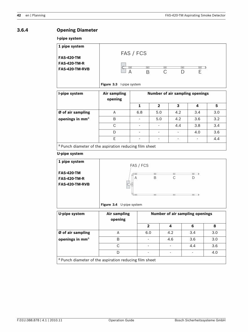
3.6.4 Opening Diameter
I-pipe system
U-pipe system
1 pipe system
FAS-420-TMFAS-420-TM-RFAS-420-TM-RVB
Figure 3.3 I-pipe system
I-pipe system Air sampling opening
Number of air sampling openings
1 2 3 4 5
Ø of air sampling
openings in mma
A 6.8 5.0 4.2 3.4 3.0
B - 5.0 4.2 3.6 3.2
C - - 4.4 3.8 3.4
D - - - 4.0 3.6
E - - - - 4.4
a Punch diameter of the aspiration reducing film sheet
1 pipe system
FAS-420-TMFAS-420-TM-RFAS-420-TM-RVB
Figure 3.4 U-pipe system
U-pipe system Air sampling opening
Number of air sampling openings
2 4 6 8
Ø of air sampling
openings in mma
A 6.0 4.2 3.4 3.0
B - 4.6 3.6 3.0
C - - 4.4 3.6
D - - - 4.0
a Punch diameter of the aspiration reducing film sheet
A B C D E
FAS / FCS
A B C D
FAS / FCS
FAS-420-TM Aspirating Smoke Detector Planning | en 43
Bosch Sicherheitssysteme GmbH Operation Guide F.01U.088.878 | 4.1 | 2010.11
M-pipe system
Double U-pipe system
1 pipe system
FAS-420-TMFAS-420-TM-RFAS-420-TM-RVB
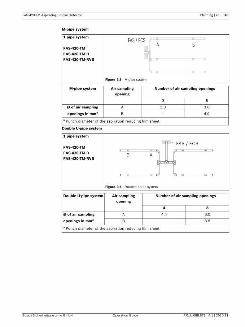
Figure 3.5 M-pipe system
M-pipe system Air sampling opening
Number of air sampling openings
3 6
Ø of air sampling
openings in mma
A 5.0 3.6
B - 4.0
a Punch diameter of the aspiration reducing film sheet
1 pipe system
FAS-420-TMFAS-420-TM-RFAS-420-TM-RVB
Figure 3.6 Double U-pipe system
Double U-pipe system Air sampling opening
Number of air sampling openings
4 8
Ø of air sampling
openings in mma
A 4.4 3.0
B - 3.8
a Punch diameter of the aspiration reducing film sheet
A BFAS / FCS
B A
FAS / FCS
44 en | Planning FAS-420-TM Aspirating Smoke Detector
F.01U.088.878 | 4.1 | 2010.11 Operation Guide Bosch Sicherheitssysteme GmbH
3.7 Planning with Single-hole MonitoringDepending on the pipe configuration, the following system parameters are used to detect a single air sampling opening or a particular number of obstructed air sampling openings.Planning is to be carried out according to regulations specified in Section 3.6 Standard Pipe Planning, page 39. Additionally, the following limiting values and opening diameters must be observed. An additional accessory (air filter, condensate separator etc.) can have an effect on the maximum pipe length.
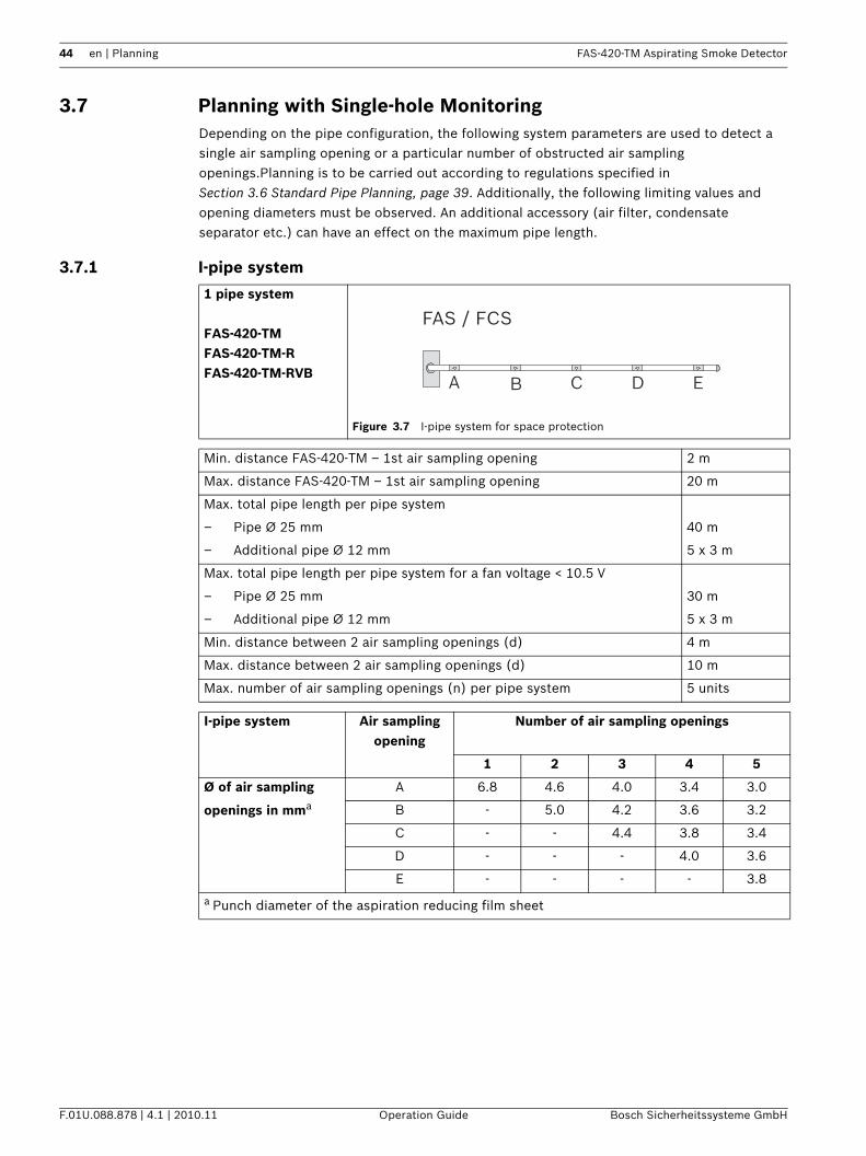
3.7.1 I-pipe system
1 pipe system
FAS-420-TMFAS-420-TM-RFAS-420-TM-RVB
Figure 3.7 I-pipe system for space protection
Min. distance FAS-420-TM – 1st air sampling opening 2 m
Max. distance FAS-420-TM – 1st air sampling opening 20 m
Max. total pipe length per pipe system
– Pipe Ø 25 mm 40 m
– Additional pipe Ø 12 mm 5 x 3 m
Max. total pipe length per pipe system for a fan voltage < 10.5 V
– Pipe Ø 25 mm 30 m
– Additional pipe Ø 12 mm 5 x 3 m
Min. distance between 2 air sampling openings (d) 4 m
Max. distance between 2 air sampling openings (d) 10 m
Max. number of air sampling openings (n) per pipe system 5 units
I-pipe system Air sampling opening
Number of air sampling openings
1 2 3 4 5
Ø of air sampling
openings in mma
A 6.8 4.6 4.0 3.4 3.0
B - 5.0 4.2 3.6 3.2
C - - 4.4 3.8 3.4
D - - - 4.0 3.6
E - - - - 3.8
a Punch diameter of the aspiration reducing film sheet
A B C D E
FAS / FCS
FAS-420-TM Aspirating Smoke Detector Planning | en 45
Bosch Sicherheitssysteme GmbH Operation Guide F.01U.088.878 | 4.1 | 2010.11
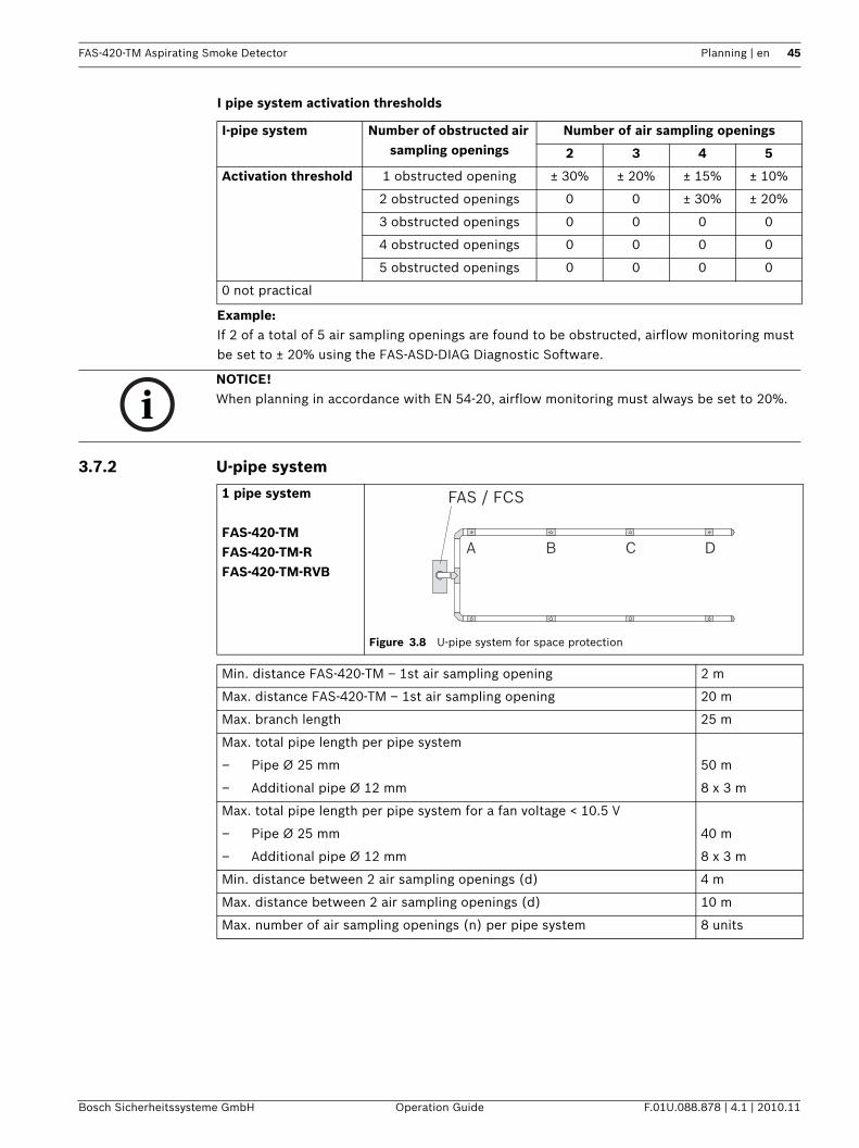
I pipe system activation thresholds
Example:If 2 of a total of 5 air sampling openings are found to be obstructed, airflow monitoring must be set to ± 20% using the FAS-ASD-DIAG Diagnostic Software.
3.7.2 U-pipe system
I-pipe system Number of obstructed air sampling openings
Number of air sampling openings
2 3 4 5
Activation threshold 1 obstructed opening ± 30% ± 20% ± 15% ± 10%
2 obstructed openings 0 0 ± 30% ± 20%
3 obstructed openings 0 0 0 0
4 obstructed openings 0 0 0 0
5 obstructed openings 0 0 0 0
0 not practical
NOTICE! When planning in accordance with EN 54-20, airflow monitoring must always be set to 20%.
1 pipe system
FAS-420-TMFAS-420-TM-RFAS-420-TM-RVB
Figure 3.8 U-pipe system for space protection
Min. distance FAS-420-TM – 1st air sampling opening 2 m
Max. distance FAS-420-TM – 1st air sampling opening 20 m
Max. branch length 25 m
Max. total pipe length per pipe system
– Pipe Ø 25 mm 50 m
– Additional pipe Ø 12 mm 8 x 3 m
Max. total pipe length per pipe system for a fan voltage < 10.5 V
– Pipe Ø 25 mm 40 m
– Additional pipe Ø 12 mm 8 x 3 m
Min. distance between 2 air sampling openings (d) 4 m
Max. distance between 2 air sampling openings (d) 10 m
Max. number of air sampling openings (n) per pipe system 8 units
A B C D
FAS / FCS
46 en | Planning FAS-420-TM Aspirating Smoke Detector
F.01U.088.878 | 4.1 | 2010.11 Operation Guide Bosch Sicherheitssysteme GmbH
U-pipe system activation thresholds
Example:If 3 of a total of 8 air sampling openings are found to be obstructed, airflow monitoring must be set to ± 25% using the FAS-ASD-DIAG Diagnostic Software.
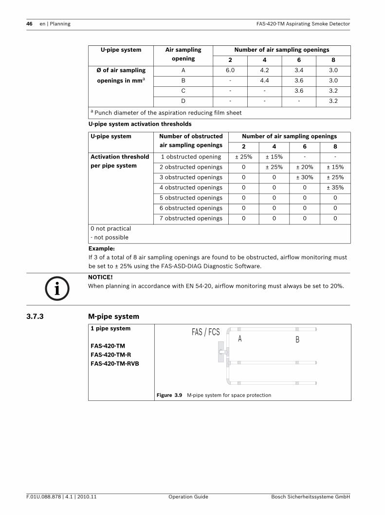
3.7.3 M-pipe system
U-pipe system Air sampling opening
Number of air sampling openings
2 4 6 8
Ø of air sampling
openings in mma
A 6.0 4.2 3.4 3.0
B - 4.4 3.6 3.0
C - - 3.6 3.2
D - - - 3.2
a Punch diameter of the aspiration reducing film sheet
U-pipe system Number of obstructed air sampling openings
Number of air sampling openings
2 4 6 8
Activation threshold per pipe system
1 obstructed opening ± 25% ± 15% - -
2 obstructed openings 0 ± 25% ± 20% ± 15%
3 obstructed openings 0 0 ± 30% ± 25%
4 obstructed openings 0 0 0 ± 35%
5 obstructed openings 0 0 0 0
6 obstructed openings 0 0 0 0
7 obstructed openings 0 0 0 0
0 not practical- not possible
NOTICE! When planning in accordance with EN 54-20, airflow monitoring must always be set to 20%.
1 pipe system
FAS-420-TMFAS-420-TM-RFAS-420-TM-RVB
Figure 3.9 M-pipe system for space protection
A BFAS / FCS
FAS-420-TM Aspirating Smoke Detector Planning | en 47
Bosch Sicherheitssysteme GmbH Operation Guide F.01U.088.878 | 4.1 | 2010.11
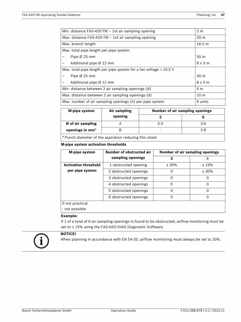
M-pipe system activation thresholds
Example:If 1 of a total of 6 air sampling openings is found to be obstructed, airflow monitoring must be set to ± 15% using the FAS-ASD-DIAG Diagnostic Software.
Min. distance FAS-420-TM – 1st air sampling opening 2 m
Max. distance FAS-420-TM – 1st air sampling opening 20 m
Max. branch length 16.5 m
Max. total pipe length per pipe system
– Pipe Ø 25 mm 50 m
– Additional pipe Ø 12 mm 8 x 3 m
Max. total pipe length per pipe system for a fan voltage < 10.5 V
– Pipe Ø 25 mm 40 m
– Additional pipe Ø 12 mm 8 x 3 m
Min. distance between 2 air sampling openings (d) 4 m
Max. distance between 2 air sampling openings (d) 10 m
Max. number of air sampling openings (n) per pipe system 6 units
M-pipe system Air sampling opening
Number of air sampling openings
3 6
Ø of air sampling
openings in mma
A 5.0 3.6
B - 3.8
a Punch diameter of the aspiration reducing film sheet
M-pipe system Number of obstructed air sampling openings
Number of air sampling openings
3 6
Activation threshold per pipe system
1 obstructed opening ± 30% ± 15%
2 obstructed openings 0 ± 30%
3 obstructed openings 0 0
4 obstructed openings 0 0
5 obstructed openings 0 0
6 obstructed openings 0 0
0 not practical- not possible
NOTICE! When planning in accordance with EN 54-20, airflow monitoring must always be set to 20%.
48 en | Planning FAS-420-TM Aspirating Smoke Detector
F.01U.088.878 | 4.1 | 2010.11 Operation Guide Bosch Sicherheitssysteme GmbH
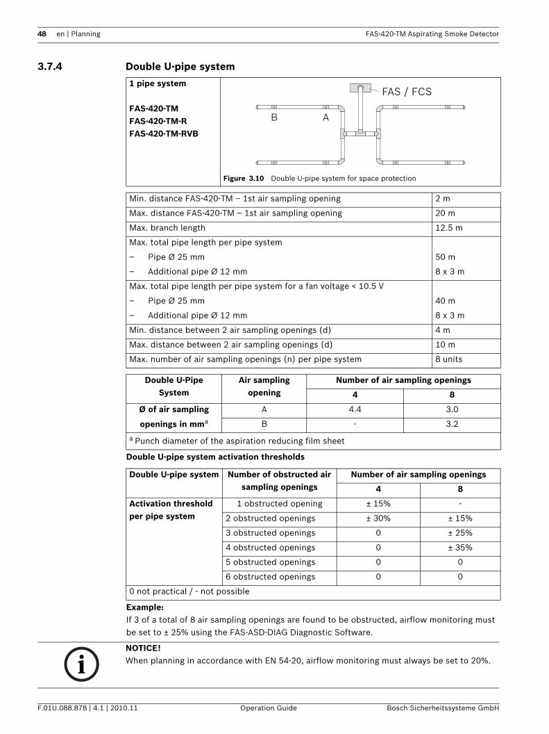
3.7.4 Double U-pipe system
Double U-pipe system activation thresholds
Example:If 3 of a total of 8 air sampling openings are found to be obstructed, airflow monitoring must be set to ± 25% using the FAS-ASD-DIAG Diagnostic Software.
1 pipe system
FAS-420-TMFAS-420-TM-RFAS-420-TM-RVB
Figure 3.10 Double U-pipe system for space protection
Min. distance FAS-420-TM – 1st air sampling opening 2 m
Max. distance FAS-420-TM – 1st air sampling opening 20 m
Max. branch length 12.5 m
Max. total pipe length per pipe system
– Pipe Ø 25 mm 50 m
– Additional pipe Ø 12 mm 8 x 3 m
Max. total pipe length per pipe system for a fan voltage < 10.5 V
– Pipe Ø 25 mm 40 m
– Additional pipe Ø 12 mm 8 x 3 m
Min. distance between 2 air sampling openings (d) 4 m
Max. distance between 2 air sampling openings (d) 10 m
Max. number of air sampling openings (n) per pipe system 8 units
Double U-Pipe System
Air sampling opening
Number of air sampling openings
4 8
Ø of air sampling
openings in mma
A 4.4 3.0
B - 3.2
a Punch diameter of the aspiration reducing film sheet
Double U-pipe system Number of obstructed air sampling openings
Number of air sampling openings
4 8
Activation threshold per pipe system
1 obstructed opening ± 15% -
2 obstructed openings ± 30% ± 15%
3 obstructed openings 0 ± 25%
4 obstructed openings 0 ± 35%
5 obstructed openings 0 0
6 obstructed openings 0 0
0 not practical / - not possible
B A
FAS / FCS
NOTICE! When planning in accordance with EN 54-20, airflow monitoring must always be set to 20%.
FAS-420-TM Aspirating Smoke Detector Planning | en 49
Bosch Sicherheitssysteme GmbH Operation Guide F.01U.088.878 | 4.1 | 2010.11
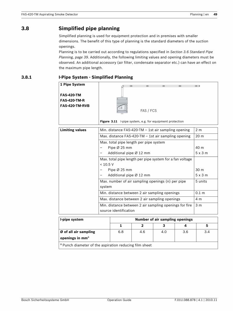
3.8 Simplified pipe planningSimplified planning is used for equipment protection and in premises with smaller dimensions. The benefit of this type of planning is the standard diameters of the suction openings.Planning is to be carried out according to regulations specified in Section 3.6 Standard Pipe Planning, page 39. Additionally, the following limiting values and opening diameters must be observed. An additional accessory (air filter, condensate separator etc.) can have an effect on the maximum pipe length.
3.8.1 I-Pipe System - Simplified Planning
1 Pipe System
FAS-420-TMFAS-420-TM-RFAS-420-TM-RVB
Figure 3.11 I-pipe system, e.g. for equipment protection
Limiting values Min. distance FAS-420-TM – 1st air sampling opening 2 m
Max. distance FAS-420-TM – 1st air sampling opening 20 m
Max. total pipe length per pipe system– Pipe Ø 25 mm– Additional pipe Ø 12 mm
40 m5 x 3 m
Max. total pipe length per pipe system for a fan voltage < 10.5 V– Pipe Ø 25 mm– Additional pipe Ø 12 mm
30 m5 x 3 m
Max. number of air sampling openings (n) per pipe system
5 units
Min. distance between 2 air sampling openings 0.1 m
Max. distance between 2 air sampling openings 4 m
Min. distance between 2 air sampling openings for fire source identification
3 m
I-pipe system Number of air sampling openings
1 2 3 4 5
Ø of all air sampling
openings in mma
6.8 4.6 4.0 3.6 3.4
a Punch diameter of the aspiration reducing film sheet
FAS / FCSE
D
C
B
A
10987654321
FAS-420-TM series
50 en | Planning FAS-420-TM Aspirating Smoke Detector
F.01U.088.878 | 4.1 | 2010.11 Operation Guide Bosch Sicherheitssysteme GmbH
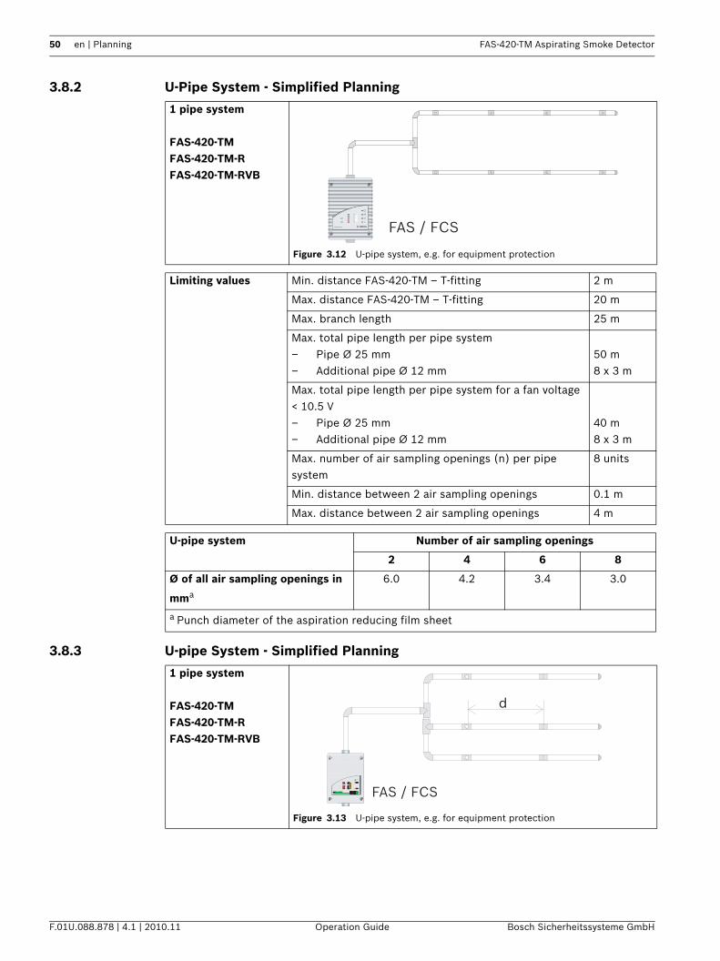
3.8.2 U-Pipe System - Simplified Planning
3.8.3 U-pipe System - Simplified Planning
1 pipe system
FAS-420-TMFAS-420-TM-RFAS-420-TM-RVB
Figure 3.12 U-pipe system, e.g. for equipment protection
Limiting values Min. distance FAS-420-TM – T-fitting 2 m
Max. distance FAS-420-TM – T-fitting 20 m
Max. branch length 25 m
Max. total pipe length per pipe system– Pipe Ø 25 mm– Additional pipe Ø 12 mm
50 m8 x 3 m
Max. total pipe length per pipe system for a fan voltage < 10.5 V– Pipe Ø 25 mm– Additional pipe Ø 12 mm
40 m8 x 3 m
Max. number of air sampling openings (n) per pipe system
8 units
Min. distance between 2 air sampling openings 0.1 m
Max. distance between 2 air sampling openings 4 m
U-pipe system Number of air sampling openings
2 4 6 8
Ø of all air sampling openings in
mma
6.0 4.2 3.4 3.0
a Punch diameter of the aspiration reducing film sheet
E
D
C
B
A
10987654321
FAS-420-TM series FAS / FCS
1 pipe system
FAS-420-TMFAS-420-TM-RFAS-420-TM-RVB
Figure 3.13 U-pipe system, e.g. for equipment protection
d
FAS / FCS
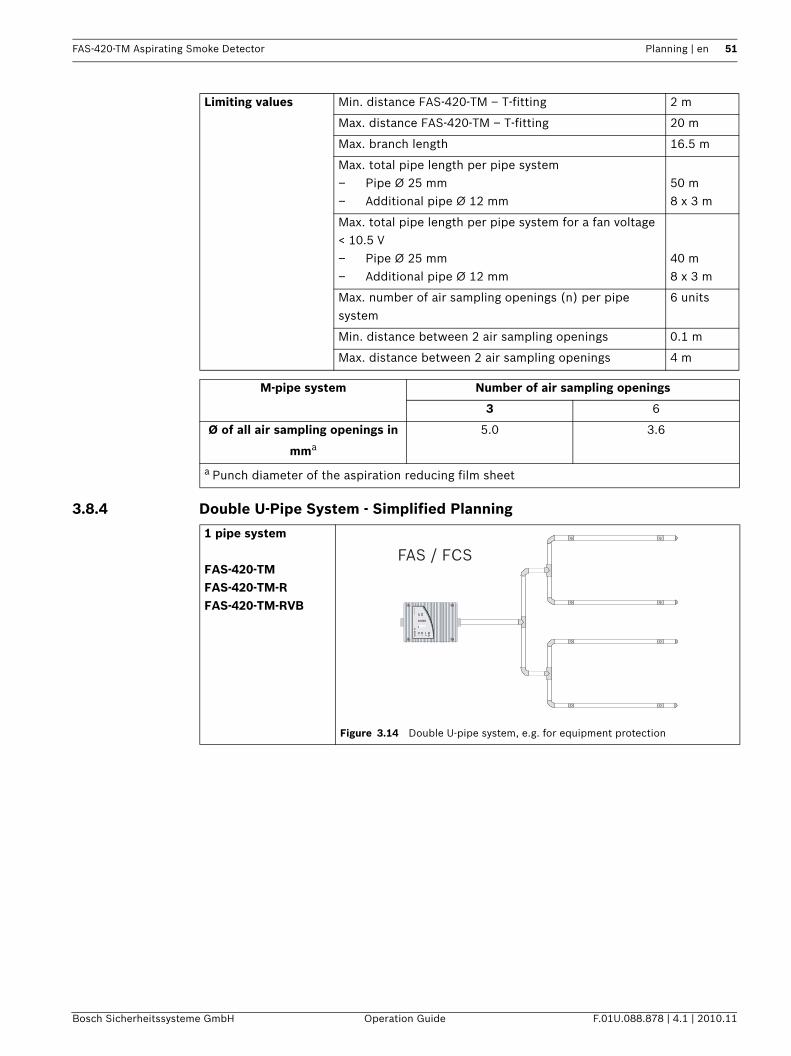
FAS-420-TM Aspirating Smoke Detector Planning | en 51
Bosch Sicherheitssysteme GmbH Operation Guide F.01U.088.878 | 4.1 | 2010.11
3.8.4 Double U-Pipe System - Simplified Planning
Limiting values Min. distance FAS-420-TM – T-fitting 2 m
Max. distance FAS-420-TM – T-fitting 20 m
Max. branch length 16.5 m
Max. total pipe length per pipe system– Pipe Ø 25 mm– Additional pipe Ø 12 mm
50 m8 x 3 m
Max. total pipe length per pipe system for a fan voltage < 10.5 V– Pipe Ø 25 mm– Additional pipe Ø 12 mm
40 m8 x 3 m
Max. number of air sampling openings (n) per pipe system
6 units
Min. distance between 2 air sampling openings 0.1 m
Max. distance between 2 air sampling openings 4 m
M-pipe system Number of air sampling openings
3 6
Ø of all air sampling openings in
mma
5.0 3.6
a Punch diameter of the aspiration reducing film sheet
1 pipe system
FAS-420-TMFAS-420-TM-RFAS-420-TM-RVB
Figure 3.14 Double U-pipe system, e.g. for equipment protection
EDCBA
10987654321
FAS
-420-TM
series
FAS / FCS
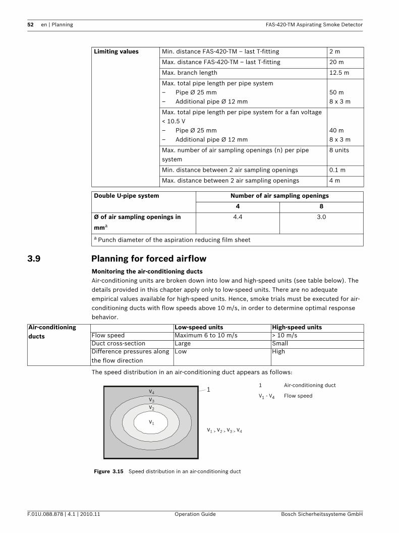
52 en | Planning FAS-420-TM Aspirating Smoke Detector
F.01U.088.878 | 4.1 | 2010.11 Operation Guide Bosch Sicherheitssysteme GmbH
3.9 Planning for forced airflowMonitoring the air-conditioning ductsAir-conditioning units are broken down into low and high-speed units (see table below). The details provided in this chapter apply only to low-speed units. There are no adequate empirical values available for high-speed units. Hence, smoke trials must be executed for air-conditioning ducts with flow speeds above 10 m/s, in order to determine optimal response behavior.
The speed distribution in an air-conditioning duct appears as follows:
Limiting values Min. distance FAS-420-TM – last T-fitting 2 m
Max. distance FAS-420-TM – last T-fitting 20 m
Max. branch length 12.5 m
Max. total pipe length per pipe system– Pipe Ø 25 mm– Additional pipe Ø 12 mm
50 m8 x 3 m
Max. total pipe length per pipe system for a fan voltage < 10.5 V– Pipe Ø 25 mm– Additional pipe Ø 12 mm
40 m8 x 3 m
Max. number of air sampling openings (n) per pipe system
8 units
Min. distance between 2 air sampling openings 0.1 m
Max. distance between 2 air sampling openings 4 m
Double U-pipe system Number of air sampling openings
4 8
Ø of air sampling openings in
mma
4.4 3.0
a Punch diameter of the aspiration reducing film sheet
Air-conditioning ducts
Low-speed units High-speed unitsFlow speed Maximum 6 to 10 m/s > 10 m/sDuct cross-section Large SmallDifference pressures along the flow direction
Low High
Figure 3.15 Speed distribution in an air-conditioning duct
1 Air-conditioning duct
V1 - V4 Flow speed1
v1
v1 > v2 > v3 > v4
v2
v3
v4
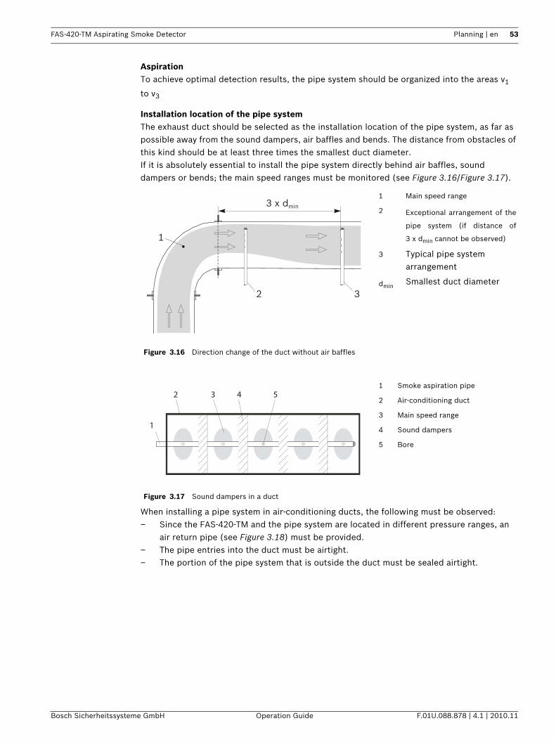
FAS-420-TM Aspirating Smoke Detector Planning | en 53
Bosch Sicherheitssysteme GmbH Operation Guide F.01U.088.878 | 4.1 | 2010.11
AspirationTo achieve optimal detection results, the pipe system should be organized into the areas v1
to v3
Installation location of the pipe systemThe exhaust duct should be selected as the installation location of the pipe system, as far as possible away from the sound dampers, air baffles and bends. The distance from obstacles of this kind should be at least three times the smallest duct diameter. If it is absolutely essential to install the pipe system directly behind air baffles, sound dampers or bends; the main speed ranges must be monitored (see Figure 3.16/Figure 3.17).
When installing a pipe system in air-conditioning ducts, the following must be observed:– Since the FAS-420-TM and the pipe system are located in different pressure ranges, an
air return pipe (see Figure 3.18) must be provided.– The pipe entries into the duct must be airtight.– The portion of the pipe system that is outside the duct must be sealed airtight.
Figure 3.16 Direction change of the duct without air baffles
1 Main speed range
2 Exceptional arrangement of the
pipe system (if distance of
3 x dmin cannot be observed)
3 Typical pipe system arrangement
dminSmallest duct diameter
Figure 3.17 Sound dampers in a duct
1 Smoke aspiration pipe
2 Air-conditioning duct
3 Main speed range
4 Sound dampers
5 Bore
3 x dmin
1
2 3
1
2 3 4 5
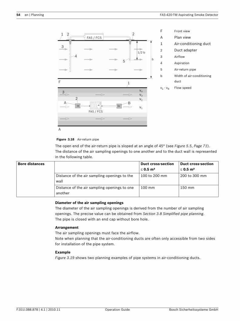
54 en | Planning FAS-420-TM Aspirating Smoke Detector
F.01U.088.878 | 4.1 | 2010.11 Operation Guide Bosch Sicherheitssysteme GmbH
The open end of the air-return pipe is sloped at an angle of 45° (see Figure 5.5, Page 71).The distance of the air sampling openings to one another and to the duct wall is represented in the following table.
Diameter of the air sampling openingsThe diameter of the air sampling openings is derived from the number of air sampling openings. The precise value can be obtained from Section 3.8 Simplified pipe planning.The pipe is closed with an end cap without bore hole.
ArrangementThe air sampling openings must face the airflow.Note when planning that the air-conditioning ducts are often only accessible from two sides for installation of the pipe system.
ExampleFigure 3.19 shows two planning examples of pipe systems in air-conditioning ducts.
Figure 3.18 Air-return pipe
F Front view
A Plan view
1 Air-conditioning duct
2 Duct adapter
3 Airflow
4 Aspiration
5 Air-return pipe
b Width of air-conditioning
duct
v1 - v4 Flow speed
1
1
5
2 2
i12345678910
4
3
3
F
v1
v2
v3
v4
A
FAS / FCS
FAS / FCS
5
1/2 b
b
2FA
S-4
20-T
Mse
ries
A B
Bore distances Duct cross-section ≤ 0.5 m²
Duct cross-section ≤ 0.5 m²
Distance of the air sampling openings to the wall
100 to 200 mm 200 to 300 mm
Distance of the air sampling openings to one another
100 mm 150 mm
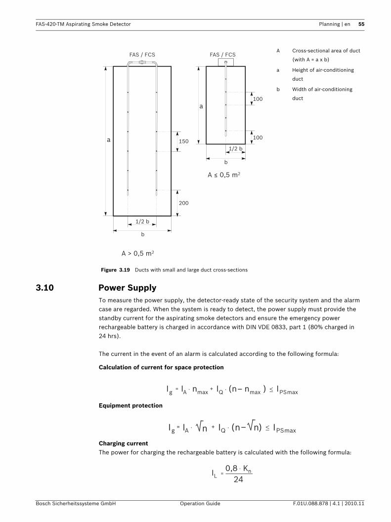
FAS-420-TM Aspirating Smoke Detector Planning | en 55
Bosch Sicherheitssysteme GmbH Operation Guide F.01U.088.878 | 4.1 | 2010.11
3.10 Power SupplyTo measure the power supply, the detector-ready state of the security system and the alarm case are regarded. When the system is ready to detect, the power supply must provide the standby current for the aspirating smoke detectors and ensure the emergency power rechargeable battery is charged in accordance with DIN VDE 0833, part 1 (80% charged in 24 hrs).
The current in the event of an alarm is calculated according to the following formula:
Calculation of current for space protection
Equipment protection
Charging currentThe power for charging the rechargeable battery is calculated with the following formula:
Figure 3.19 Ducts with small and large duct cross-sections
A Cross-sectional area of duct
(with A = a x b)
a Height of air-conditioning
duct
b Width of air-conditioning
duct
FAS / FCSFAS / FCS
A ≤ 0,5 m2
A > 0,5 m2
a100
100
200
150
b
1/2 b
b
1/2 b
a
I I IIg A nmax Q PS= . nmax
+ . (n _ ) max
I I IIg A n Q PS= . + . (n _ ) maxn
n=.
L0,8 K
24I
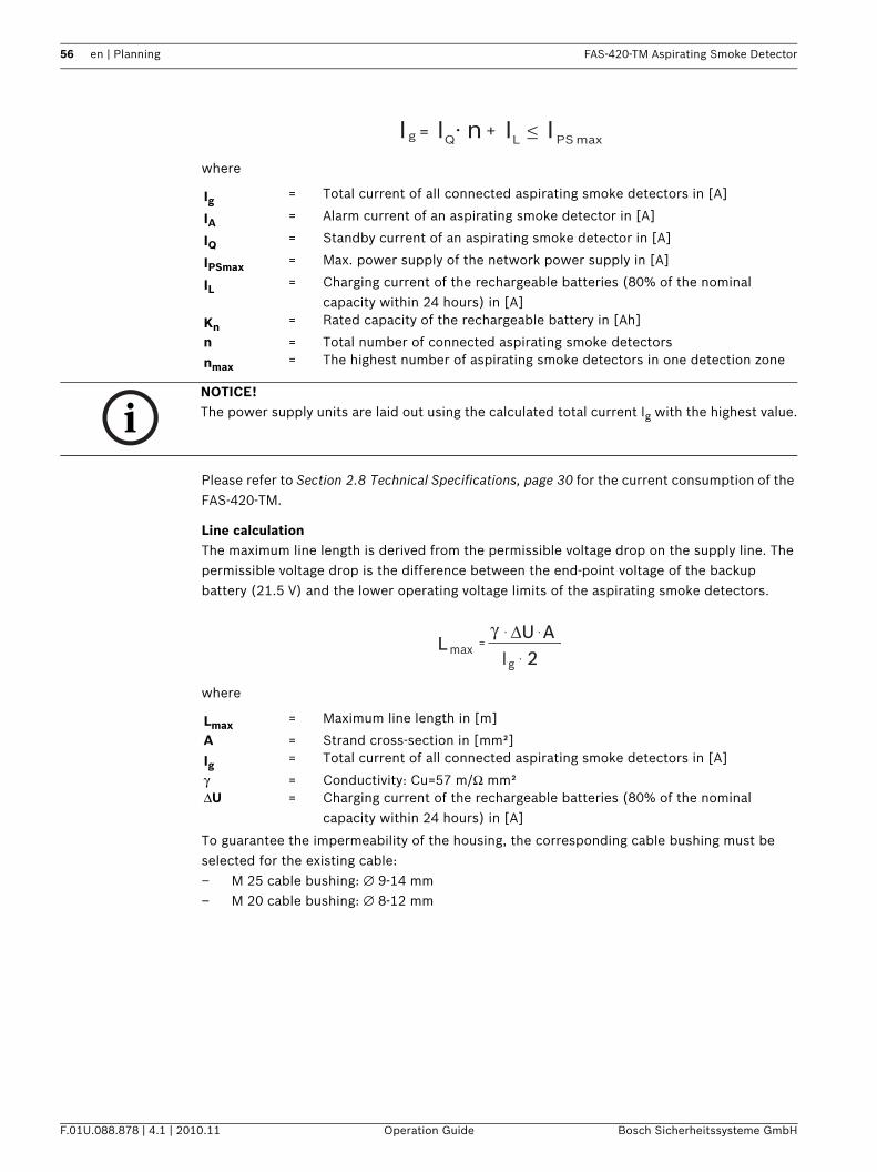
56 en | Planning FAS-420-TM Aspirating Smoke Detector
F.01U.088.878 | 4.1 | 2010.11 Operation Guide Bosch Sicherheitssysteme GmbH
where
Please refer to Section 2.8 Technical Specifications, page 30 for the current consumption of the FAS-420-TM.
Line calculationThe maximum line length is derived from the permissible voltage drop on the supply line. The permissible voltage drop is the difference between the end-point voltage of the backup battery (21.5 V) and the lower operating voltage limits of the aspirating smoke detectors.
where
To guarantee the impermeability of the housing, the corresponding cable bushing must be selected for the existing cable:– M 25 cable bushing: ∅ 9-14 mm– M 20 cable bushing: ∅ 8-12 mm
Ig = Total current of all connected aspirating smoke detectors in [A]
IA = Alarm current of an aspirating smoke detector in [A]
IQ = Standby current of an aspirating smoke detector in [A]
IPSmax = Max. power supply of the network power supply in [A]
IL = Charging current of the rechargeable batteries (80% of the nominal capacity within 24 hours) in [A]
Kn = Rated capacity of the rechargeable battery in [Ah]
n = Total number of connected aspirating smoke detectors
nmax = The highest number of aspirating smoke detectors in one detection zone
I I Ig Q PS= n +max
. IL
NOTICE! The power supply units are laid out using the calculated total current Ig with the highest value.
Lmax = Maximum line length in [m]
A = Strand cross-section in [mm²]
Ig = Total current of all connected aspirating smoke detectors in [A]
γ = Conductivity: Cu=57 m/Ω mm²ΔU = Charging current of the rechargeable batteries (80% of the nominal
capacity within 24 hours) in [A]
Igmax =
. .γL
ΔU.
A2
FAS-420-TM Aspirating Smoke Detector Planning | en 57
Bosch Sicherheitssysteme GmbH Operation Guide F.01U.088.878 | 4.1 | 2010.11
Emergency power calculationThe rated capacity is calculated according to the following formula:
The factor 1.25 used in the formula is only applicable with bridging times ≤ 24 hours.The "Fire System Designer" (FSD) enables case-specific calculations to be carried out for planning Bosch LSN improved version fire panels.
Kn = Rated capacity of the backup batteries in [Ah]
IQ = Standby current of an aspirating smoke detector in [A]
n = Total number of connected aspirating smoke detectorst = Required bridging time in [hrs]
Ig = Total current of all connected aspirating smoke detectors in [A]
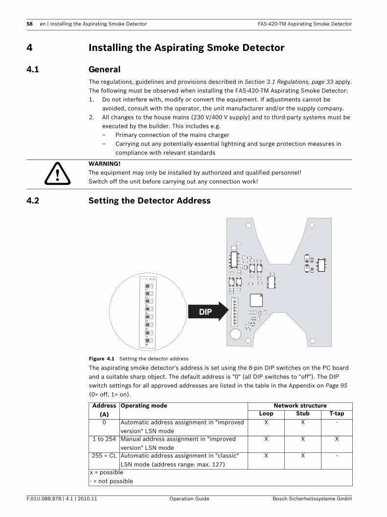
58 en | Installing the Aspirating Smoke Detector FAS-420-TM Aspirating Smoke Detector
F.01U.088.878 | 4.1 | 2010.11 Operation Guide Bosch Sicherheitssysteme GmbH
4 Installing the Aspirating Smoke Detector
4.1 GeneralThe regulations, guidelines and provisions described in Section 3.1 Regulations, page 33 apply.The following must be observed when installing the FAS-420-TM Aspirating Smoke Detector:1. Do not interfere with, modify or convert the equipment. If adjustments cannot be
avoided, consult with the operator, the unit manufacturer and/or the supply company.2. All changes to the house mains (230 V/400 V supply) and to third-party systems must be
executed by the builder. This includes e.g.– Primary connection of the mains charger– Carrying out any potentially essential lightning and surge protection measures in
compliance with relevant standards
4.2 Setting the Detector Address
Figure 4.1 Setting the detector address
The aspirating smoke detector's address is set using the 8-pin DIP switches on the PC board and a suitable sharp object. The default address is "0" (all DIP switches to "off"). The DIP switch settings for all approved addresses are listed in the table in the Appendix on Page 95 (0= off, 1= on).
WARNING! The equipment may only be installed by authorized and qualified personnel!Switch off the unit before carrying out any connection work!
Address (A)
Operating mode Network structureLoop Stub T-tap
0 Automatic address assignment in "improved version" LSN mode
X X -
1 to 254 Manual address assignment in "improved version" LSN mode
X X X
255 = CL Automatic address assignment in "classic" LSN mode (address range: max. 127)
X X -
x = possible- = not possible
DIPDIP
ON
12
34
56
78
ON
12
34
56
78
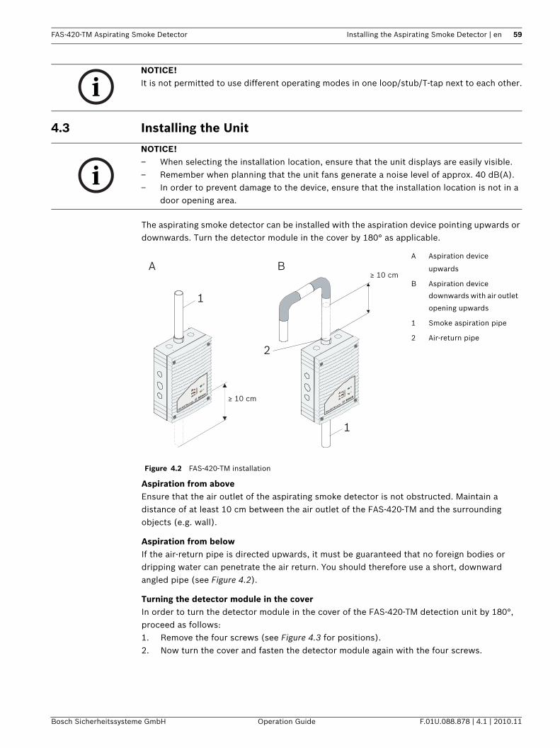
FAS-420-TM Aspirating Smoke Detector Installing the Aspirating Smoke Detector | en 59
Bosch Sicherheitssysteme GmbH Operation Guide F.01U.088.878 | 4.1 | 2010.11
4.3 Installing the Unit
The aspirating smoke detector can be installed with the aspiration device pointing upwards or downwards. Turn the detector module in the cover by 180° as applicable.
Aspiration from aboveEnsure that the air outlet of the aspirating smoke detector is not obstructed. Maintain a distance of at least 10 cm between the air outlet of the FAS-420-TM and the surrounding objects (e.g. wall).
Aspiration from belowIf the air-return pipe is directed upwards, it must be guaranteed that no foreign bodies or dripping water can penetrate the air return. You should therefore use a short, downward angled pipe (see Figure 4.2).
Turning the detector module in the coverIn order to turn the detector module in the cover of the FAS-420-TM detection unit by 180°, proceed as follows:1. Remove the four screws (see Figure 4.3 for positions).2. Now turn the cover and fasten the detector module again with the four screws.
NOTICE! It is not permitted to use different operating modes in one loop/stub/T-tap next to each other.
NOTICE! – When selecting the installation location, ensure that the unit displays are easily visible.– Remember when planning that the unit fans generate a noise level of approx. 40 dB(A).– In order to prevent damage to the device, ensure that the installation location is not in a
door opening area.
Figure 4.2 FAS-420-TM installation
A Aspiration device
upwards
B Aspiration device
downwards with air outlet
opening upwards
1 Smoke aspiration pipe
2 Air-return pipe
FAS-420-TM series
FAS-420-TM series
≥ 10 cm
≥ 10 cm
1
1
2
A B
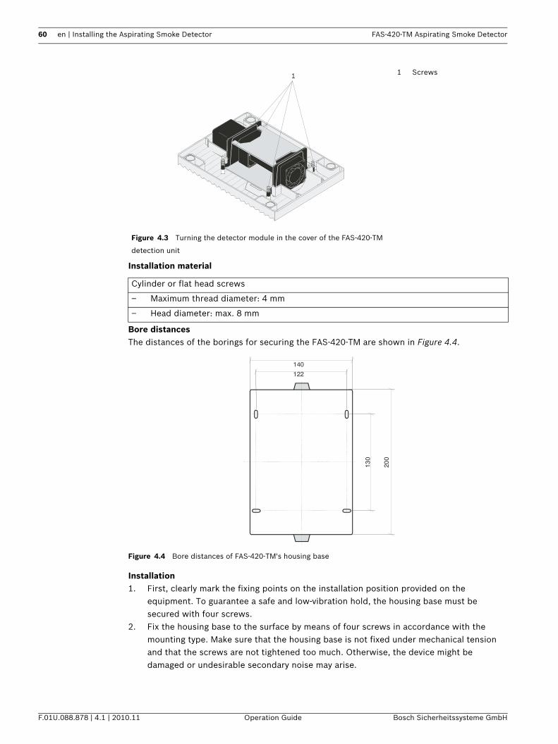
60 en | Installing the Aspirating Smoke Detector FAS-420-TM Aspirating Smoke Detector
F.01U.088.878 | 4.1 | 2010.11 Operation Guide Bosch Sicherheitssysteme GmbH
Installation material
Bore distancesThe distances of the borings for securing the FAS-420-TM are shown in Figure 4.4.
Figure 4.4 Bore distances of FAS-420-TM's housing base
Installation1. First, clearly mark the fixing points on the installation position provided on the
equipment. To guarantee a safe and low-vibration hold, the housing base must be secured with four screws.
2. Fix the housing base to the surface by means of four screws in accordance with the mounting type. Make sure that the housing base is not fixed under mechanical tension and that the screws are not tightened too much. Otherwise, the device might be damaged or undesirable secondary noise may arise.
Figure 4.3 Turning the detector module in the cover of the FAS-420-TM
detection unit
1 Screws
Cylinder or flat head screws
– Maximum thread diameter: 4 mm
– Head diameter: max. 8 mm
1
200
140122
130
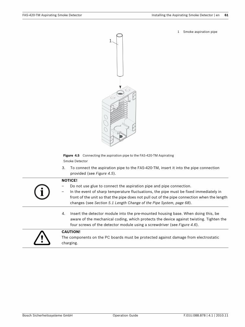
FAS-420-TM Aspirating Smoke Detector Installing the Aspirating Smoke Detector | en 61
Bosch Sicherheitssysteme GmbH Operation Guide F.01U.088.878 | 4.1 | 2010.11
3. To connect the aspiration pipe to the FAS-420-TM, insert it into the pipe connection provided (see Figure 4.5).
4. Insert the detector module into the pre-mounted housing base. When doing this, be aware of the mechanical coding, which protects the device against twisting. Tighten the four screws of the detector module using a screwdriver (see Figure 4.6).
Figure 4.5 Connecting the aspiration pipe to the FAS-420-TM Aspirating
Smoke Detector
1 Smoke aspiration pipe
1
NOTICE! – Do not use glue to connect the aspiration pipe and pipe connection.– In the event of sharp temperature fluctuations, the pipe must be fixed immediately in
front of the unit so that the pipe does not pull out of the pipe connection when the length changes (see Section 5.1 Length Change of the Pipe System, page 68).
CAUTION! The components on the PC boards must be protected against damage from electrostatic charging.
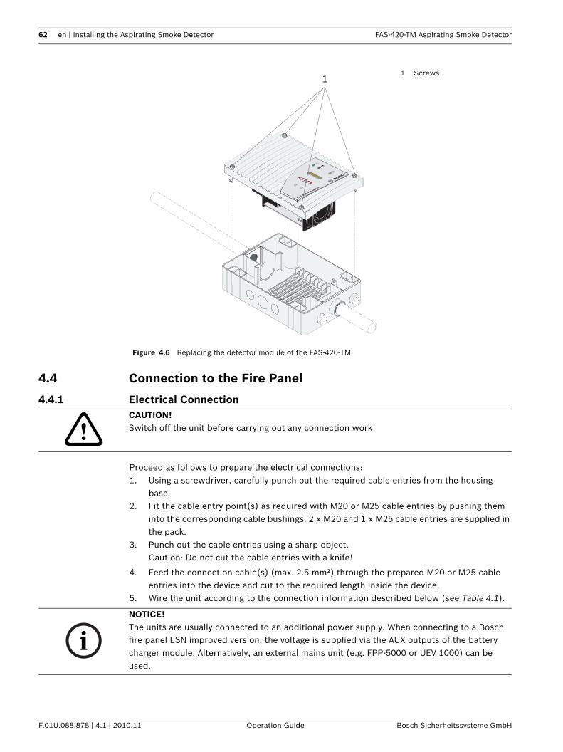
62 en | Installing the Aspirating Smoke Detector FAS-420-TM Aspirating Smoke Detector
F.01U.088.878 | 4.1 | 2010.11 Operation Guide Bosch Sicherheitssysteme GmbH
4.4 Connection to the Fire Panel
4.4.1 Electrical Connection
Proceed as follows to prepare the electrical connections:1. Using a screwdriver, carefully punch out the required cable entries from the housing
base.2. Fit the cable entry point(s) as required with M20 or M25 cable entries by pushing them
into the corresponding cable bushings. 2 x M20 and 1 x M25 cable entries are supplied in the pack.
3. Punch out the cable entries using a sharp object. Caution: Do not cut the cable entries with a knife!
4. Feed the connection cable(s) (max. 2.5 mm²) through the prepared M20 or M25 cable entries into the device and cut to the required length inside the device.
5. Wire the unit according to the connection information described below (see Table 4.1).
Figure 4.6 Replacing the detector module of the FAS-420-TM
1 Screws
FAS-420-TM series
1
CAUTION! Switch off the unit before carrying out any connection work!
NOTICE! The units are usually connected to an additional power supply. When connecting to a Bosch fire panel LSN improved version, the voltage is supplied via the AUX outputs of the battery charger module. Alternatively, an external mains unit (e.g. FPP-5000 or UEV 1000) can be used.
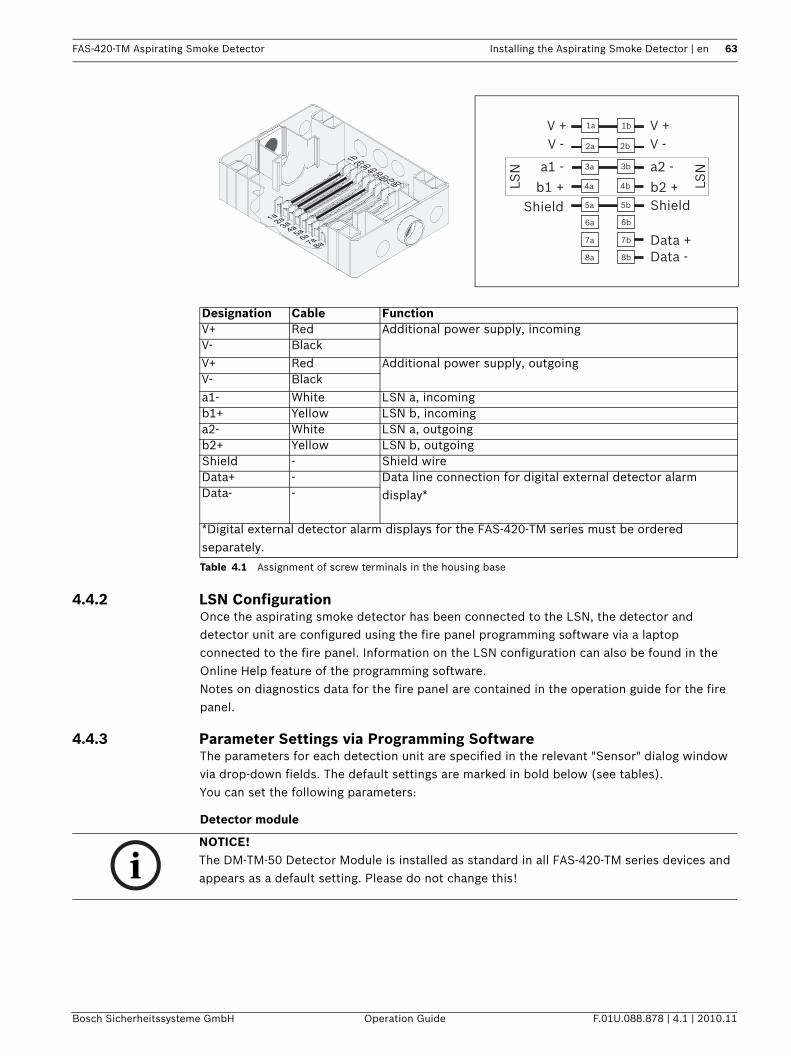
FAS-420-TM Aspirating Smoke Detector Installing the Aspirating Smoke Detector | en 63
Bosch Sicherheitssysteme GmbH Operation Guide F.01U.088.878 | 4.1 | 2010.11
Table 4.1 Assignment of screw terminals in the housing base
4.4.2 LSN ConfigurationOnce the aspirating smoke detector has been connected to the LSN, the detector and detector unit are configured using the fire panel programming software via a laptop connected to the fire panel. Information on the LSN configuration can also be found in the Online Help feature of the programming software.Notes on diagnostics data for the fire panel are contained in the operation guide for the fire panel.
4.4.3 Parameter Settings via Programming SoftwareThe parameters for each detection unit are specified in the relevant "Sensor" dialog window via drop-down fields. The default settings are marked in bold below (see tables).You can set the following parameters:
Detector module
Designation Cable FunctionV+ Red Additional power supply, incomingV- BlackV+ Red Additional power supply, outgoingV- Blacka1- White LSN a, incomingb1+ Yellow LSN b, incominga2- White LSN a, outgoingb2+ Yellow LSN b, outgoingShield - Shield wireData+ - Data line connection for digital external detector alarm
display*Data- -
*Digital external detector alarm displays for the FAS-420-TM series must be ordered separately.
V -V +
b1 +
a1 -
Shield
V -V +
a2 -
b2 +Shield
Data +Data -
LSN
LSN
1b
2b
3b
4b
5b
6a 6b
7a
8a 8b
7b
2a
3a
4a
5a
1a
NOTICE! The DM-TM-50 Detector Module is installed as standard in all FAS-420-TM series devices and appears as a default setting. Please do not change this!
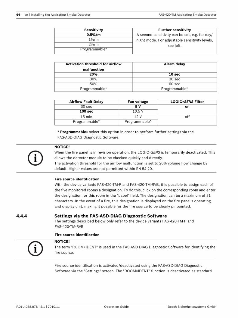
64 en | Installing the Aspirating Smoke Detector FAS-420-TM Aspirating Smoke Detector
F.01U.088.878 | 4.1 | 2010.11 Operation Guide Bosch Sicherheitssysteme GmbH
Fire source identificationWith the device variants FAS-420-TM-R and FAS-420-TM-RVB, it is possible to assign each of the five monitored rooms a designation. To do this, click on the corresponding room and enter the designation for this room in the "Label" field. The designation can be a maximum of 31 characters. In the event of a fire, this designation is displayed on the fire panel's operating and display unit, making it possible for the fire source to be clearly pinpointed.
4.4.4 Settings via the FAS-ASD-DIAG Diagnostic SoftwareThe settings described below only refer to the device variants FAS-420-TM-R and FAS-420-TM-RVB.
Fire source identification
Fire source identification is activated/deactivated using the FAS-ASD-DIAG Diagnostic Software via the "Settings" screen. The "ROOM×IDENT" function is deactivated as standard.
Sensitivity Further sensitivity0.5%/m A second sensitivity can be set, e.g. for day/
night mode. For adjustable sensitivity levels, see left.
1%/m2%/m
Programmable*
Activation threshold for airflow malfunction
Alarm delay
20% 10 sec30% 30 sec50% 60 sec
Programmable* Programmable*
Airflow Fault Delay Fan voltage LOGIC×SENS Filter30 sec 9 V on
100 sec 10.5 V15 min 12 V off
Programmable* Programmable*
* Programmable= select this option in order to perform further settings via the FAS-ASD-DIAG Diagnostic Software.
NOTICE! When the fire panel is in revision operation, the LOGIC×SENS is temporarily deactivated. This allows the detector module to be checked quickly and directly.The activation threshold for the airflow malfunction is set to 20% volume flow change by default. Higher values are not permitted within EN 54-20.
NOTICE! The term "ROOM×IDENT" is used in the FAS-ASD-DIAG Diagnostic Software for identifying the fire source.
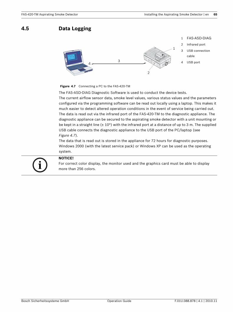
FAS-420-TM Aspirating Smoke Detector Installing the Aspirating Smoke Detector | en 65
Bosch Sicherheitssysteme GmbH Operation Guide F.01U.088.878 | 4.1 | 2010.11
4.5 Data Logging
The FAS-ASD-DIAG Diagnostic Software is used to conduct the device tests. The current airflow sensor data, smoke level values, various status values and the parameters configured via the programming software can be read out locally using a laptop. This makes it much easier to detect altered operation conditions in the event of service being carried out.The data is read out via the infrared port of the FAS-420-TM to the diagnostic appliance. The diagnostic appliance can be secured to the aspirating smoke detector with a unit mounting or be kept in a straight line (± 10°) with the infrared port at a distance of up to 3 m. The supplied USB cable connects the diagnostic appliance to the USB port of the PC/laptop (see Figure 4.7). The data that is read out is stored in the appliance for 72 hours for diagnostic purposes.Windows 2000 (with the latest service pack) or Windows XP can be used as the operating system.
Figure 4.7 Connecting a PC to the FAS-420-TM
1 FAS-ASD-DIAG
2 Infrared port
3 USB connection
cable
4 USB port
1
2
34
NOTICE! For correct color display, the monitor used and the graphics card must be able to display more than 256 colors.
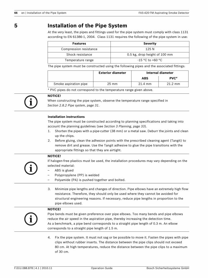
66 en | Installation of the Pipe System FAS-420-TM Aspirating Smoke Detector
F.01U.088.878 | 4.1 | 2010.11 Operation Guide Bosch Sicherheitssysteme GmbH
5 Installation of the Pipe SystemAt the very least, the pipes and fittings used for the pipe system must comply with class 1131 according to EN 61386-1, 2004. Class 1131 requires the following of the pipe system in use:
The pipe system must be constructed using the following pipes and the associated fittings:
* PVC pipes do not correspond to the temperature range given above.
Installation instructionsThe pipe system must be constructed according to planning specifications and taking into account the planning guidelines (see Section 3 Planning, page 33).1. Shorten the pipes with a pipe-cutter (38 mm) or a metal saw. Deburr the joints and clean
up the chips.2. Before gluing, clean the adhesion points with the prescribed cleaning agent (Tangit) to
remove dirt and grease. Use the Tangit adhesive to glue the pipe transitions with the appropriate fittings so that they are airtight.
3. Minimize pipe lengths and changes of direction. Pipe elbows have an extremely high flow resistance. Therefore, they should only be used where they cannot be avoided for structural engineering reasons. If necessary, reduce pipe lengths in proportion to the pipe elbows used.
4. Fix the pipe system. It must not sag or be possible to move it. Fasten the pipes with pipe clips without rubber inserts. The distance between the pipe clips should not exceed 80 cm. At high temperatures, reduce the distance between the pipe clips to a maximum of 30 cm.
Features Severity
Compression resistance 125 N
Shock resistance 0.5 kg, drop height of 100 mm
Temperature range -15 °C to +60 °C
Exterior diameter Internal diameter
ABS PVC*
Smoke aspiration pipe 25 mm 21.4 mm 21.2 mm
NOTICE! When constructing the pipe system, observe the temperature range specified in Section 2.8.2 Pipe system, page 31.
NOTICE! If halogen-free plastics must be used, the installation procedures may vary depending on the selected material: – ABS is glued– Polypropylene (PP) is welded– Polyamide (PA) is pushed together and bolted.
NOTICE! Pipe bends must be given preference over pipe elbows. Too many bends and pipe elbows reduce the air speed in the aspiration pipe, thereby increasing the detection time.As a benchmark, a pipe bend corresponds to a straight pipe length of 0.3 m. An elbow corresponds to a straight pipe length of 1.5 m.
FAS-420-TM Aspirating Smoke Detector Installation of the Pipe System | en 67
Bosch Sicherheitssysteme GmbH Operation Guide F.01U.088.878 | 4.1 | 2010.11
5. Close open pipe ends with an end cap.
NOTICE! Do not use pipe clips with rubber inserts since these do not allow length extensions and the pipe system could thus bend or even tear.
NOTICE! On completion, test the pipe system:– For tightness– For fault-free connections– For correct planning of the air sampling openings.
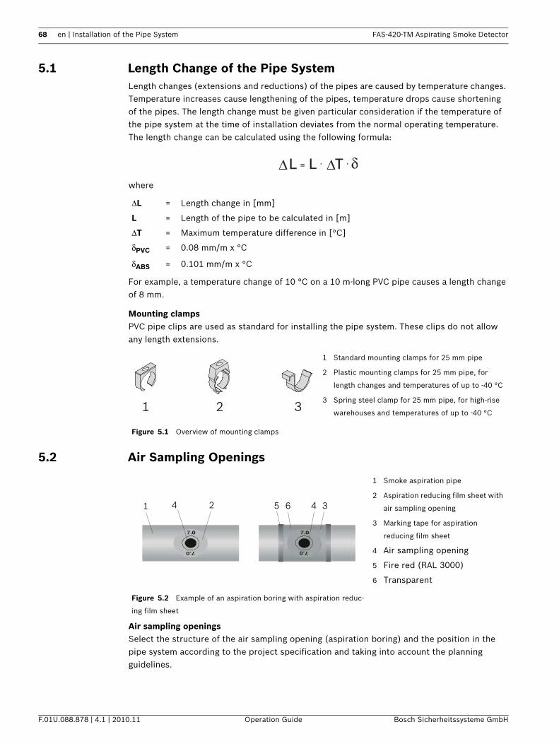
68 en | Installation of the Pipe System FAS-420-TM Aspirating Smoke Detector
F.01U.088.878 | 4.1 | 2010.11 Operation Guide Bosch Sicherheitssysteme GmbH
5.1 Length Change of the Pipe SystemLength changes (extensions and reductions) of the pipes are caused by temperature changes. Temperature increases cause lengthening of the pipes, temperature drops cause shortening of the pipes. The length change must be given particular consideration if the temperature of the pipe system at the time of installation deviates from the normal operating temperature.The length change can be calculated using the following formula:
where
For example, a temperature change of 10 °C on a 10 m-long PVC pipe causes a length change of 8 mm.
Mounting clampsPVC pipe clips are used as standard for installing the pipe system. These clips do not allow any length extensions.
5.2 Air Sampling Openings
Air sampling openingsSelect the structure of the air sampling opening (aspiration boring) and the position in the pipe system according to the project specification and taking into account the planning guidelines.
ΔL = Length change in [mm]
L = Length of the pipe to be calculated in [m]
ΔT = Maximum temperature difference in [°C]
δPVC = 0.08 mm/m x °C
δABS = 0.101 mm/m x °C
Figure 5.1 Overview of mounting clamps
1 Standard mounting clamps for 25 mm pipe
2 Plastic mounting clamps for 25 mm pipe, for
length changes and temperatures of up to -40 °C
3 Spring steel clamp for 25 mm pipe, for high-rise
warehouses and temperatures of up to -40 °C1 2 3
Figure 5.2 Example of an aspiration boring with aspiration reduc-
ing film sheet
1 Smoke aspiration pipe
2 Aspiration reducing film sheet with
air sampling opening
3 Marking tape for aspiration
reducing film sheet
4 Air sampling opening
5 Fire red (RAL 3000)
6 Transparent
1 364 452
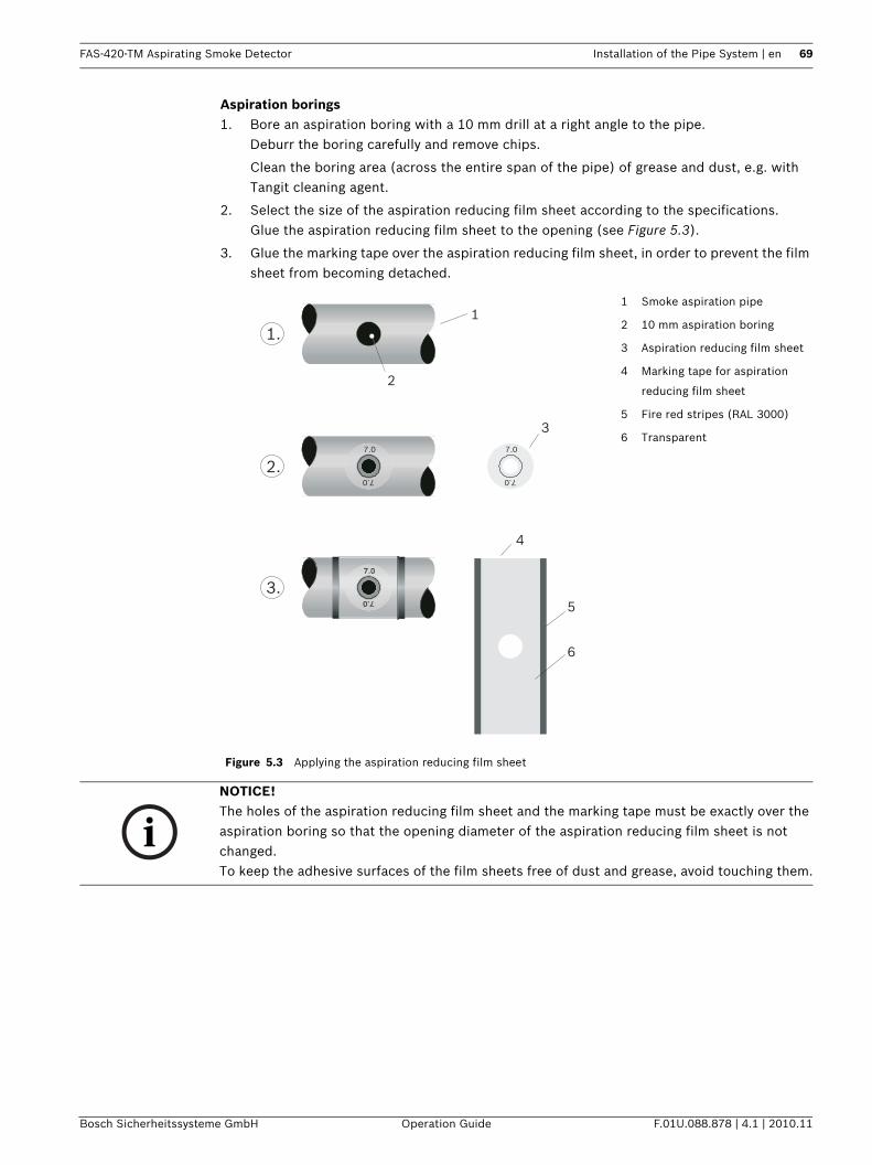
FAS-420-TM Aspirating Smoke Detector Installation of the Pipe System | en 69
Bosch Sicherheitssysteme GmbH Operation Guide F.01U.088.878 | 4.1 | 2010.11
Aspiration borings1. Bore an aspiration boring with a 10 mm drill at a right angle to the pipe.
Deburr the boring carefully and remove chips.
Clean the boring area (across the entire span of the pipe) of grease and dust, e.g. with Tangit cleaning agent.
2. Select the size of the aspiration reducing film sheet according to the specifications.Glue the aspiration reducing film sheet to the opening (see Figure 5.3).
3. Glue the marking tape over the aspiration reducing film sheet, in order to prevent the film sheet from becoming detached.
Figure 5.3 Applying the aspiration reducing film sheet
1 Smoke aspiration pipe
2 10 mm aspiration boring
3 Aspiration reducing film sheet
4 Marking tape for aspiration
reducing film sheet
5 Fire red stripes (RAL 3000)
6 Transparent
7.07.0
7.0
7.0
7.0
7.0
1
1.
2
3
4
5
6
2.
3.
NOTICE! The holes of the aspiration reducing film sheet and the marking tape must be exactly over the aspiration boring so that the opening diameter of the aspiration reducing film sheet is not changed.To keep the adhesive surfaces of the film sheets free of dust and grease, avoid touching them.
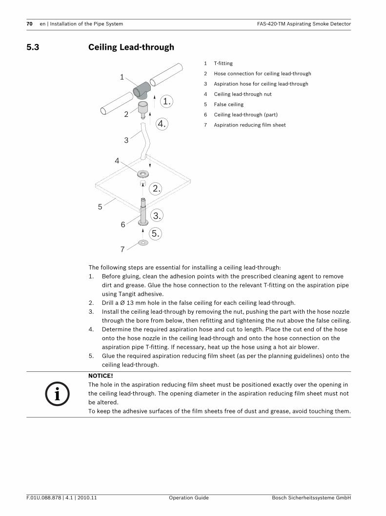
70 en | Installation of the Pipe System FAS-420-TM Aspirating Smoke Detector
F.01U.088.878 | 4.1 | 2010.11 Operation Guide Bosch Sicherheitssysteme GmbH
5.3 Ceiling Lead-through
The following steps are essential for installing a ceiling lead-through:1. Before gluing, clean the adhesion points with the prescribed cleaning agent to remove
dirt and grease. Glue the hose connection to the relevant T-fitting on the aspiration pipe using Tangit adhesive.
2. Drill a Ø 13 mm hole in the false ceiling for each ceiling lead-through.3. Install the ceiling lead-through by removing the nut, pushing the part with the hose nozzle
through the bore from below, then refitting and tightening the nut above the false ceiling.4. Determine the required aspiration hose and cut to length. Place the cut end of the hose
onto the hose nozzle in the ceiling lead-through and onto the hose connection on the aspiration pipe T-fitting. If necessary, heat up the hose using a hot air blower.
5. Glue the required aspiration reducing film sheet (as per the planning guidelines) onto the ceiling lead-through.
1 T-fitting
2 Hose connection for ceiling lead-through
3 Aspiration hose for ceiling lead-through
4 Ceiling lead-through nut
5 False ceiling
6 Ceiling lead-through (part)
7 Aspiration reducing film sheet
1
1.2
3
5
4
7
4.
2.
5.
3.6
NOTICE! The hole in the aspiration reducing film sheet must be positioned exactly over the opening in the ceiling lead-through. The opening diameter in the aspiration reducing film sheet must not be altered.To keep the adhesive surfaces of the film sheets free of dust and grease, avoid touching them.
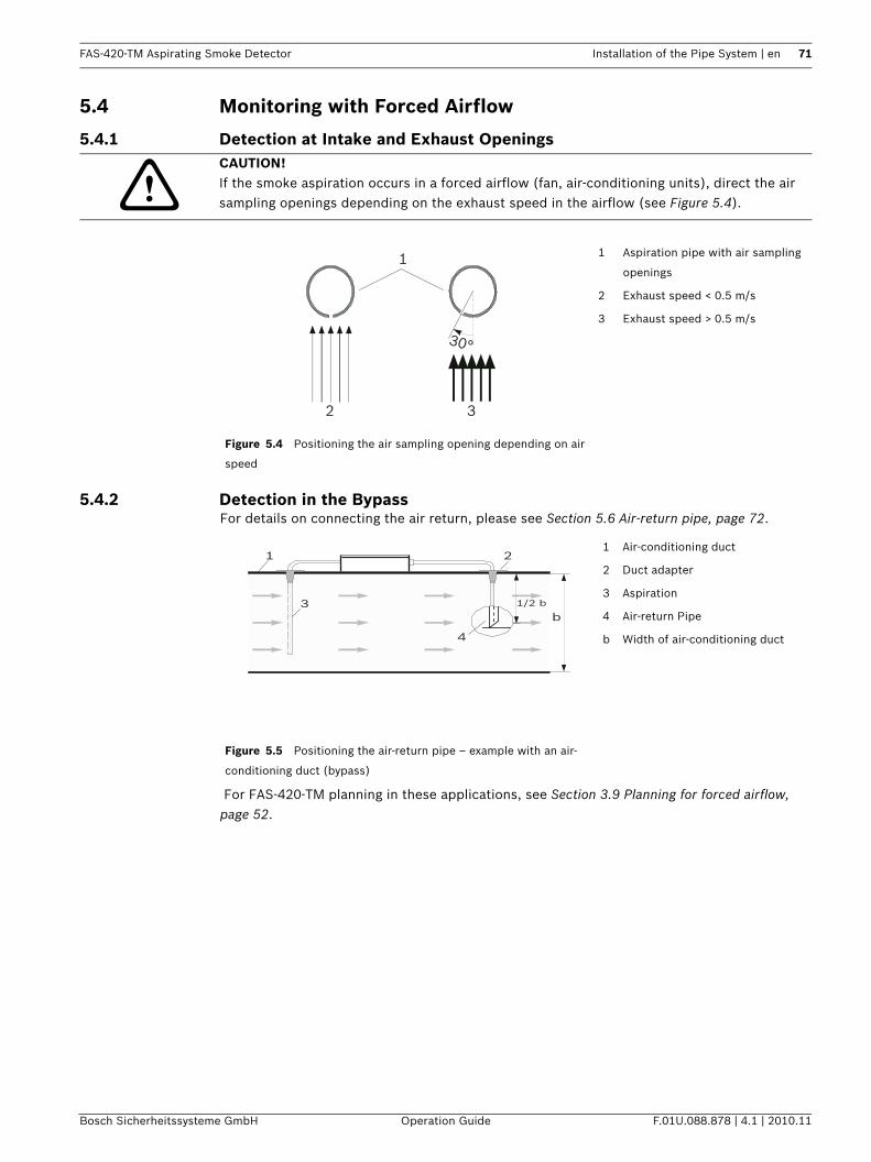
FAS-420-TM Aspirating Smoke Detector Installation of the Pipe System | en 71
Bosch Sicherheitssysteme GmbH Operation Guide F.01U.088.878 | 4.1 | 2010.11
5.4 Monitoring with Forced Airflow
5.4.1 Detection at Intake and Exhaust Openings
5.4.2 Detection in the BypassFor details on connecting the air return, please see Section 5.6 Air-return pipe, page 72.
For FAS-420-TM planning in these applications, see Section 3.9 Planning for forced airflow, page 52.
CAUTION! If the smoke aspiration occurs in a forced airflow (fan, air-conditioning units), direct the air sampling openings depending on the exhaust speed in the airflow (see Figure 5.4).
Figure 5.4 Positioning the air sampling opening depending on air
speed
1 Aspiration pipe with air sampling
openings
2 Exhaust speed < 0.5 m/s
3 Exhaust speed > 0.5 m/s
1
2 3
30°
Figure 5.5 Positioning the air-return pipe – example with an air-
conditioning duct (bypass)
1 Air-conditioning duct
2 Duct adapter
3 Aspiration
4 Air-return Pipe
b Width of air-conditioning duct
1 2
3
4
b1/2 b
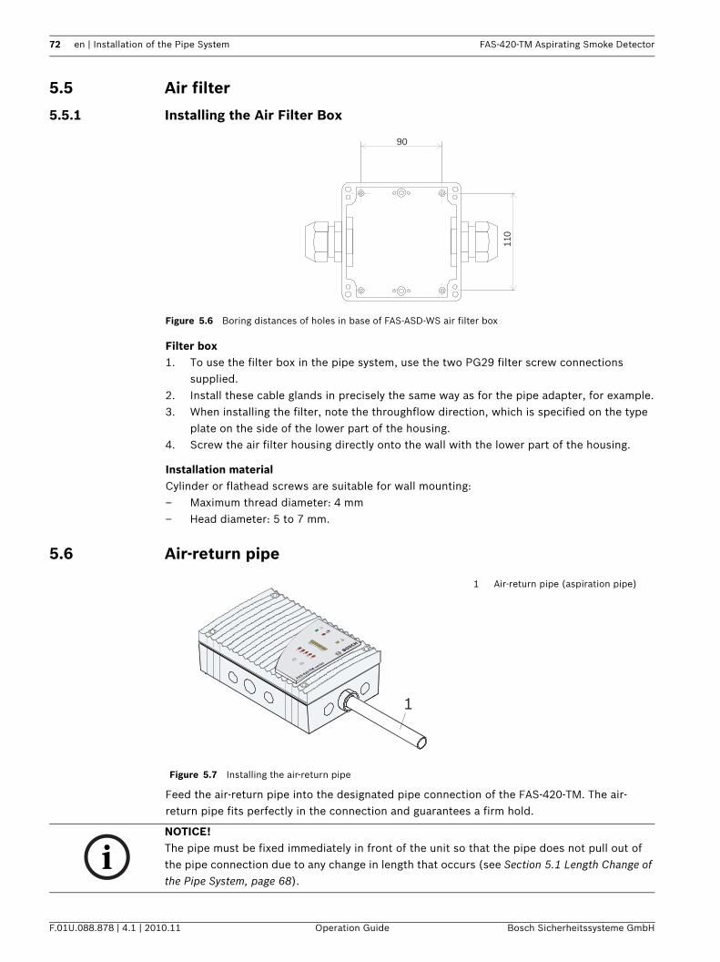
72 en | Installation of the Pipe System FAS-420-TM Aspirating Smoke Detector
F.01U.088.878 | 4.1 | 2010.11 Operation Guide Bosch Sicherheitssysteme GmbH
5.5 Air filter
5.5.1 Installing the Air Filter Box
Figure 5.6 Boring distances of holes in base of FAS-ASD-WS air filter box
Filter box1. To use the filter box in the pipe system, use the two PG29 filter screw connections
supplied.2. Install these cable glands in precisely the same way as for the pipe adapter, for example.3. When installing the filter, note the throughflow direction, which is specified on the type
plate on the side of the lower part of the housing.4. Screw the air filter housing directly onto the wall with the lower part of the housing.
Installation materialCylinder or flathead screws are suitable for wall mounting:– Maximum thread diameter: 4 mm– Head diameter: 5 to 7 mm.
5.6 Air-return pipe
Feed the air-return pipe into the designated pipe connection of the FAS-420-TM. The air-return pipe fits perfectly in the connection and guarantees a firm hold.
110
90
Figure 5.7 Installing the air-return pipe
1 Air-return pipe (aspiration pipe)
FAS-420-TM serie
s
1
NOTICE! The pipe must be fixed immediately in front of the unit so that the pipe does not pull out of the pipe connection due to any change in length that occurs (see Section 5.1 Length Change of the Pipe System, page 68).
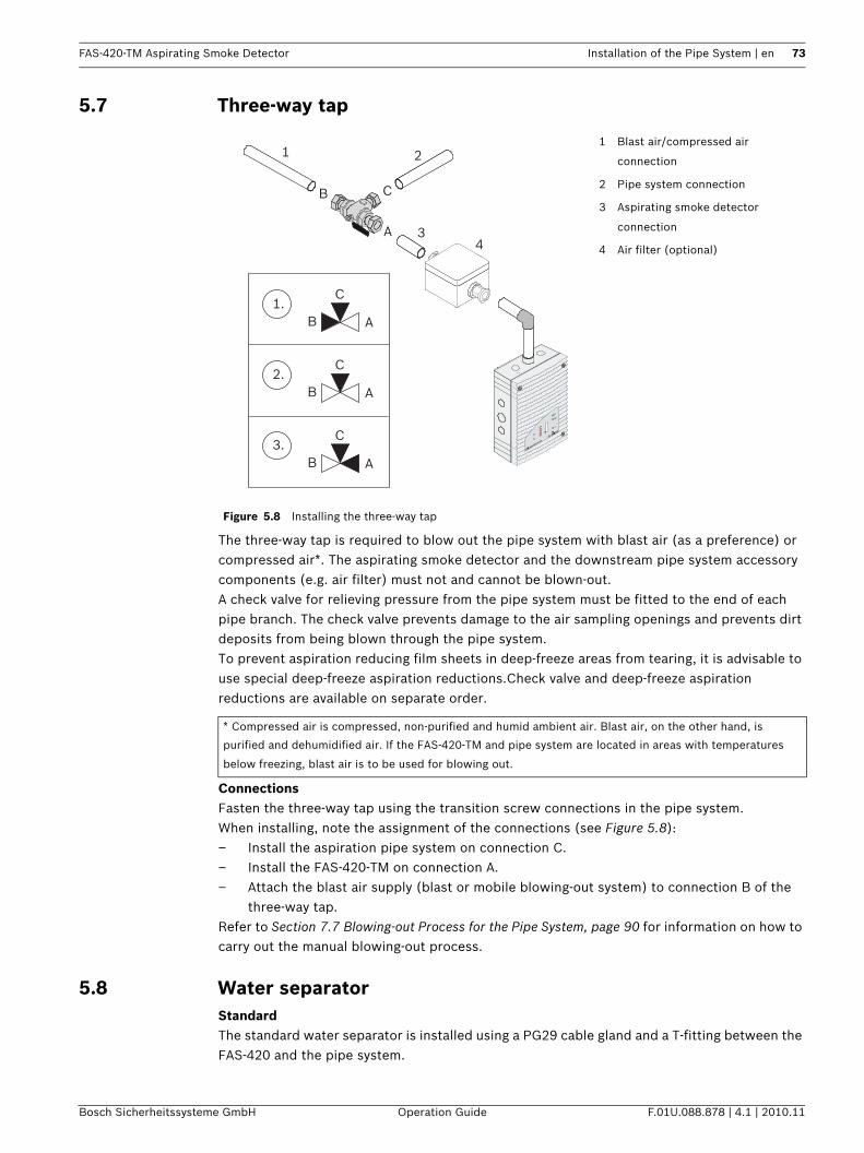
FAS-420-TM Aspirating Smoke Detector Installation of the Pipe System | en 73
Bosch Sicherheitssysteme GmbH Operation Guide F.01U.088.878 | 4.1 | 2010.11
5.7 Three-way tap
The three-way tap is required to blow out the pipe system with blast air (as a preference) or compressed air*. The aspirating smoke detector and the downstream pipe system accessory components (e.g. air filter) must not and cannot be blown-out.A check valve for relieving pressure from the pipe system must be fitted to the end of each pipe branch. The check valve prevents damage to the air sampling openings and prevents dirt deposits from being blown through the pipe system.To prevent aspiration reducing film sheets in deep-freeze areas from tearing, it is advisable to use special deep-freeze aspiration reductions.Check valve and deep-freeze aspiration reductions are available on separate order.
ConnectionsFasten the three-way tap using the transition screw connections in the pipe system.When installing, note the assignment of the connections (see Figure 5.8):– Install the aspiration pipe system on connection C.– Install the FAS-420-TM on connection A.– Attach the blast air supply (blast or mobile blowing-out system) to connection B of the
three-way tap.Refer to Section 7.7 Blowing-out Process for the Pipe System, page 90 for information on how to carry out the manual blowing-out process.
5.8 Water separatorStandardThe standard water separator is installed using a PG29 cable gland and a T-fitting between the FAS-420 and the pipe system.
Figure 5.8 Installing the three-way tap
1 Blast air/compressed air
connection
2 Pipe system connection
3 Aspirating smoke detector
connection
4 Air filter (optional)
* Compressed air is compressed, non-purified and humid ambient air. Blast air, on the other hand, is
purified and dehumidified air. If the FAS-420-TM and pipe system are located in areas with temperatures
below freezing, blast air is to be used for blowing out.
FAS-420-TM serie
s
A
B C
1 2
34
AB
C2.
AB
C3.
AB
C1.
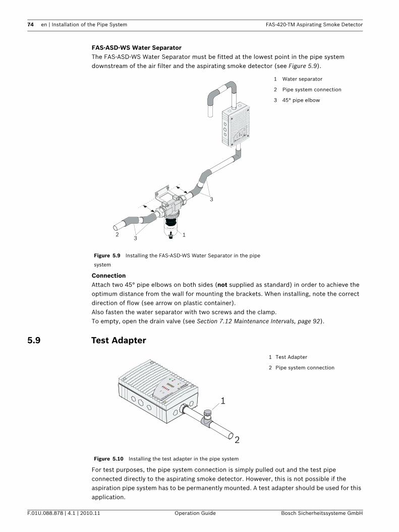
74 en | Installation of the Pipe System FAS-420-TM Aspirating Smoke Detector
F.01U.088.878 | 4.1 | 2010.11 Operation Guide Bosch Sicherheitssysteme GmbH
FAS-ASD-WS Water SeparatorThe FAS-ASD-WS Water Separator must be fitted at the lowest point in the pipe system downstream of the air filter and the aspirating smoke detector (see Figure 5.9).
ConnectionAttach two 45° pipe elbows on both sides (not supplied as standard) in order to achieve the optimum distance from the wall for mounting the brackets. When installing, note the correct direction of flow (see arrow on plastic container).Also fasten the water separator with two screws and the clamp.To empty, open the drain valve (see Section 7.12 Maintenance Intervals, page 92).
5.9 Test Adapter
For test purposes, the pipe system connection is simply pulled out and the test pipe connected directly to the aspirating smoke detector. However, this is not possible if the aspiration pipe system has to be permanently mounted. A test adapter should be used for this application.
Figure 5.9 Installing the FAS-ASD-WS Water Separator in the pipe
system
1 Water separator
2 Pipe system connection
3 45° pipe elbow
123
3
FAS-420-TM serie
s
Figure 5.10 Installing the test adapter in the pipe system
1 Test Adapter
2 Pipe system connection
FAS-420-TM serie
s
1
2

FAS-420-TM Aspirating Smoke Detector Installation of the Pipe System | en 75
Bosch Sicherheitssysteme GmbH Operation Guide F.01U.088.878 | 4.1 | 2010.11
The test adapter is glued into the pipe system in the direct vicinity of the aspirating smoke detector. During normal operation, the test adapter must always be closed. It is only opened for maintenance and service purposes in order to admit test gas or smoke.
CAUTION! Once the detection system of the aspirating smoke detector and the alarm transfer have been tested (see Page 79), the test adapter must be closed again; otherwise there will be an airflow malfunction!
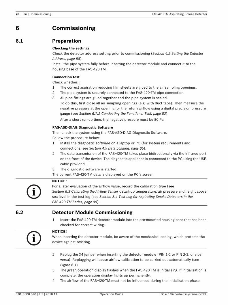
76 en | Commissioning FAS-420-TM Aspirating Smoke Detector
F.01U.088.878 | 4.1 | 2010.11 Operation Guide Bosch Sicherheitssysteme GmbH
6 Commissioning
6.1 PreparationChecking the settingsCheck the detector address setting prior to commissioning (Section 4.2 Setting the Detector Address, page 58).Install the pipe system fully before inserting the detector module and connect it to the housing base of the FAS-420-TM.
Connection testCheck whether…1. The correct aspiration reducing film sheets are glued to the air sampling openings.2. The pipe system is securely connected to the FAS-420-TM pipe connection.3. All pipe fittings are glued together and the pipe system is sealed.
To do this, first close all air sampling openings (e.g. with duct tape). Then measure the negative pressure at the opening for the return airflow using a digital precision pressure gauge (see Section 6.7.2 Conducting the Functional Test, page 82).
After a short run-up time, the negative pressure must be 80 Pa.
FAS-ASD-DIAG Diagnostic SoftwareThen check the system using the FAS-ASD-DIAG Diagnostic Software.Follow the procedure below:1. Install the diagnostic software on a laptop or PC (for system requirements and
connections, see Section 4.5 Data Logging, page 65).2. The data transmission of the FAS-420-TM takes place bidirectionally via the infrared port
on the front of the device. The diagnostic appliance is connected to the PC using the USB cable provided.
3. The diagnostic software is started.The current FAS-420-TM data is displayed on the PC’s screen.
6.2 Detector Module Commissioning1. Insert the FAS-420-TM detector module into the pre-mounted housing base that has been
checked for correct wiring.
2. Replug the X4 jumper when inserting the detector module (PIN 1-2 or PIN 2-3, or vice versa). Replugging will cause airflow calibration to be carried out automatically (see Figure 6.1).
3. The green operation display flashes when the FAS-420-TM is initializing. If initialization is complete, the operation display lights up permanently.
4. The airflow of the FAS-420-TM must not be influenced during the initialization phase.
NOTICE! For a later evaluation of the airflow value, record the calibration type (see Section 6.3 Calibrating the Airflow Sensor), start-up temperature, air pressure and height above sea level in the test log (see Section 8.4 Test Log for Aspirating Smoke Detectors in the FAS-420-TM Series, page 99).
NOTICE! When inserting the detector module, be aware of the mechanical coding, which protects the device against twisting.
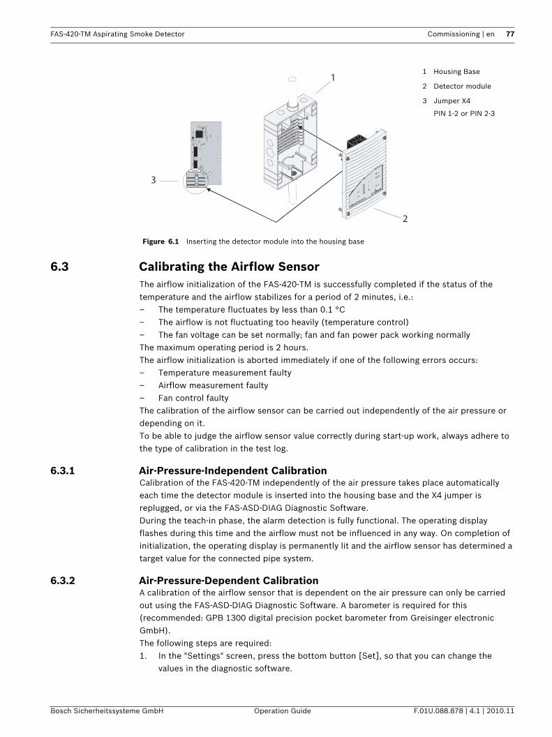
FAS-420-TM Aspirating Smoke Detector Commissioning | en 77
Bosch Sicherheitssysteme GmbH Operation Guide F.01U.088.878 | 4.1 | 2010.11
6.3 Calibrating the Airflow SensorThe airflow initialization of the FAS-420-TM is successfully completed if the status of the temperature and the airflow stabilizes for a period of 2 minutes, i.e.:– The temperature fluctuates by less than 0.1 °C– The airflow is not fluctuating too heavily (temperature control)– The fan voltage can be set normally; fan and fan power pack working normallyThe maximum operating period is 2 hours.The airflow initialization is aborted immediately if one of the following errors occurs:– Temperature measurement faulty– Airflow measurement faulty– Fan control faultyThe calibration of the airflow sensor can be carried out independently of the air pressure or depending on it. To be able to judge the airflow sensor value correctly during start-up work, always adhere to the type of calibration in the test log.
6.3.1 Air-Pressure-Independent CalibrationCalibration of the FAS-420-TM independently of the air pressure takes place automatically each time the detector module is inserted into the housing base and the X4 jumper is replugged, or via the FAS-ASD-DIAG Diagnostic Software.During the teach-in phase, the alarm detection is fully functional. The operating display flashes during this time and the airflow must not be influenced in any way. On completion of initialization, the operating display is permanently lit and the airflow sensor has determined a target value for the connected pipe system.
6.3.2 Air-Pressure-Dependent CalibrationA calibration of the airflow sensor that is dependent on the air pressure can only be carried out using the FAS-ASD-DIAG Diagnostic Software. A barometer is required for this (recommended: GPB 1300 digital precision pocket barometer from Greisinger electronic GmbH).The following steps are required:1. In the "Settings" screen, press the bottom button [Set], so that you can change the
values in the diagnostic software.
Figure 6.1 Inserting the detector module into the housing base
1 Housing Base
2 Detector module
3 Jumper X4
PIN 1-2 or PIN 2-3
X4
12
3
X2
X3
X1
FAS-420-TM serie
s
1
2
3
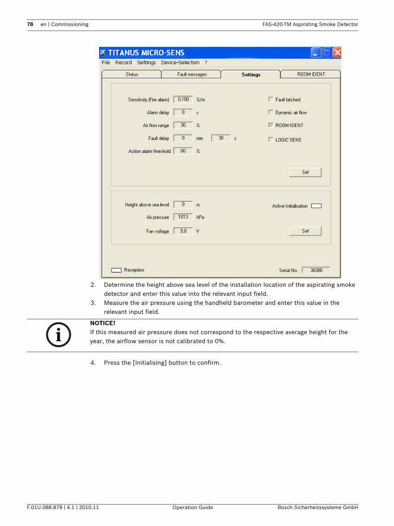
78 en | Commissioning FAS-420-TM Aspirating Smoke Detector
F.01U.088.878 | 4.1 | 2010.11 Operation Guide Bosch Sicherheitssysteme GmbH
2. Determine the height above sea level of the installation location of the aspirating smoke detector and enter this value into the relevant input field.
3. Measure the air pressure using the handheld barometer and enter this value in the relevant input field.
4. Press the [Initialising] button to confirm.
NOTICE! If this measured air pressure does not correspond to the respective average height for the year, the airflow sensor is not calibrated to 0%.
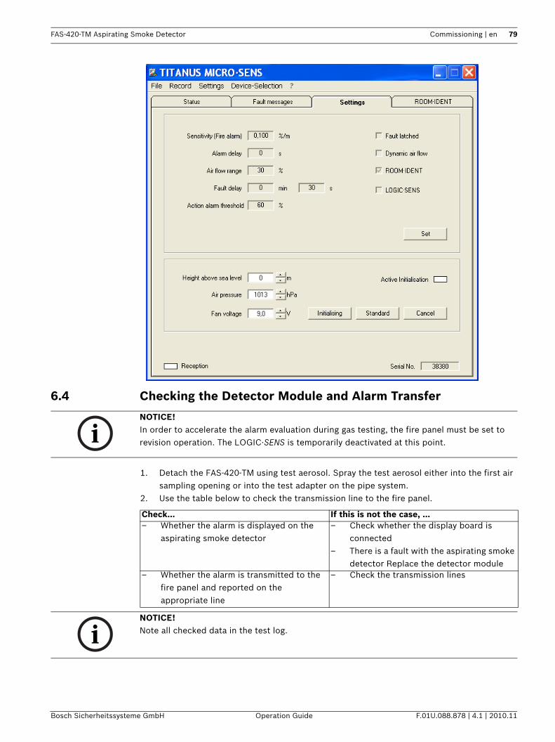
FAS-420-TM Aspirating Smoke Detector Commissioning | en 79
Bosch Sicherheitssysteme GmbH Operation Guide F.01U.088.878 | 4.1 | 2010.11
6.4 Checking the Detector Module and Alarm Transfer
1. Detach the FAS-420-TM using test aerosol. Spray the test aerosol either into the first air sampling opening or into the test adapter on the pipe system.
2. Use the table below to check the transmission line to the fire panel.
NOTICE! In order to accelerate the alarm evaluation during gas testing, the fire panel must be set to revision operation. The LOGIC·SENS is temporarily deactivated at this point.
Check… If this is not the case, ...– Whether the alarm is displayed on the
aspirating smoke detector– Check whether the display board is
connected– There is a fault with the aspirating smoke
detector Replace the detector module– Whether the alarm is transmitted to the
fire panel and reported on the appropriate line
– Check the transmission lines
NOTICE! Note all checked data in the test log.
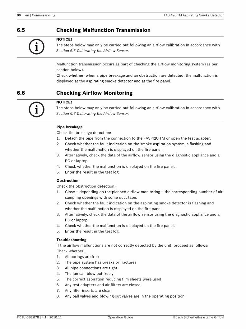
80 en | Commissioning FAS-420-TM Aspirating Smoke Detector
F.01U.088.878 | 4.1 | 2010.11 Operation Guide Bosch Sicherheitssysteme GmbH
6.5 Checking Malfunction Transmission
Malfunction transmission occurs as part of checking the airflow monitoring system (as per section below).Check whether, when a pipe breakage and an obstruction are detected, the malfunction is displayed at the aspirating smoke detector and at the fire panel.
6.6 Checking Airflow Monitoring
Pipe breakageCheck the breakage detection:1. Detach the pipe from the connection to the FAS-420-TM or open the test adapter.2. Check whether the fault indication on the smoke aspiration system is flashing and
whether the malfunction is displayed on the fire panel.3. Alternatively, check the data of the airflow sensor using the diagnostic appliance and a
PC or laptop.4. Check whether the malfunction is displayed on the fire panel.5. Enter the result in the test log.
ObstructionCheck the obstruction detection:1. Close – depending on the planned airflow monitoring – the corresponding number of air
sampling openings with some duct tape.2. Check whether the fault indication on the aspirating smoke detector is flashing and
whether the malfunction is displayed on the fire panel.3. Alternatively, check the data of the airflow sensor using the diagnostic appliance and a
PC or laptop.4. Check whether the malfunction is displayed on the fire panel.5. Enter the result in the test log.
TroubleshootingIf the airflow malfunctions are not correctly detected by the unit, proceed as follows:Check whether…1. All borings are free2. The pipe system has breaks or fractures3. All pipe connections are tight4. The fan can blow out freely5. The correct aspiration reducing film sheets were used6. Any test adapters and air filters are closed7. Any filter inserts are clean8. Any ball valves and blowing-out valves are in the operating position.
NOTICE! The steps below may only be carried out following an airflow calibration in accordance with Section 6.3 Calibrating the Airflow Sensor.
NOTICE! The steps below may only be carried out following an airflow calibration in accordance with Section 6.3 Calibrating the Airflow Sensor.
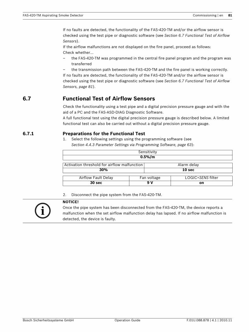
FAS-420-TM Aspirating Smoke Detector Commissioning | en 81
Bosch Sicherheitssysteme GmbH Operation Guide F.01U.088.878 | 4.1 | 2010.11
If no faults are detected, the functionality of the FAS-420-TM and/or the airflow sensor is checked using the test pipe or diagnostic software (see Section 6.7 Functional Test of Airflow Sensors).If the airflow malfunctions are not displayed on the fire panel, proceed as follows: Check whether… – the FAS-420-TM was programmed in the central fire panel program and the program was
transferred– the transmission path between the FAS-420-TM and the fire panel is working correctly.If no faults are detected, the functionality of the FAS-420-TM and/or the airflow sensor is checked using the test pipe or diagnostic software (see Section 6.7 Functional Test of Airflow Sensors, page 81).
6.7 Functional Test of Airflow SensorsCheck the functionality using a test pipe and a digital precision pressure gauge and with the aid of a PC and the FAS-ASD-DIAG Diagnostic Software.A full functional test using the digital precision pressure gauge is described below. A limited functional test can also be carried out without a digital precision pressure gauge.
6.7.1 Preparations for the Functional Test1. Select the following settings using the programming software (see
Section 4.4.3 Parameter Settings via Programming Software, page 63):
2. Disconnect the pipe system from the FAS-420-TM.
Sensitivity0.5%/m
Activation threshold for airflow malfunction Alarm delay30% 10 sec
Airflow Fault Delay Fan voltage LOGIC×SENS filter30 sec 9 V on
NOTICE! Once the pipe system has been disconnected from the FAS-420-TM, the device reports a malfunction when the set airflow malfunction delay has lapsed. If no airflow malfunction is detected, the device is faulty.
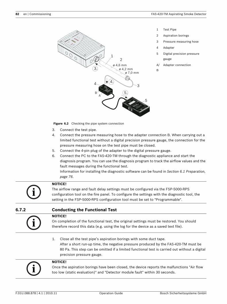
82 en | Commissioning FAS-420-TM Aspirating Smoke Detector
F.01U.088.878 | 4.1 | 2010.11 Operation Guide Bosch Sicherheitssysteme GmbH
3. Connect the test pipe.4. Connect the pressure measuring hose to the adapter connection B. When carrying out a
limited functional test without a digital precision pressure gauge, the connection for the pressure measuring hose on the test pipe must be closed.
5. Connect the 4-pin plug of the adapter to the digital pressure gauge.6. Connect the PC to the FAS-420-TM through the diagnostic appliance and start the
diagnosis program. You can use the diagnosis program to track the airflow values and the fault messages during the functional test.Information for installing the diagnostic software can be found in Section 6.1 Preparation, page 76.
6.7.2 Conducting the Functional Test
1. Close all the test pipe’s aspiration borings with some duct tape.After a short run-up time, the negative pressure produced by the FAS-420-TM must be 80 Pa. This step can be omitted if a limited functional test is carried out without a digital precision pressure gauge.
Figure 6.2 Checking the pipe system connection
1 Test Pipe
2 Aspiration borings
3 Pressure measuring hose
4 Adapter
5 Digital precision pressure
gauge
A/
B
Adapter connection
FAS-420-TM series
BA
ø 7,0 mmø 4,2 mm
ø 4,6 mm
1
5.
2
34
5
3.
4.
NOTICE! The airflow range and fault delay settings must be configured via the FSP-5000-RPS configuration tool on the fire panel. To configure the settings with the diagnostic tool, the setting in the FSP-5000-RPS configuration tool must be set to "Programmable".
NOTICE! On completion of the functional test, the original settings must be restored. You should therefore record this data (e.g. using the log for the device as a saved text file).
NOTICE! Once the aspiration borings have been closed, the device reports the malfunctions "Air flow too low (static evaluation)" and "Detector module fault" within 30 seconds.
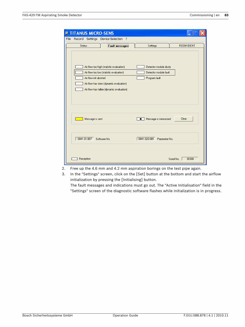
FAS-420-TM Aspirating Smoke Detector Commissioning | en 83
Bosch Sicherheitssysteme GmbH Operation Guide F.01U.088.878 | 4.1 | 2010.11
2. Free up the 4.6 mm and 4.2 mm aspiration borings on the test pipe again.3. In the "Settings" screen, click on the [Set] button at the bottom and start the airflow
initialization by pressing the [Initialising] button.The fault messages and indications must go out. The "Active Initialisation" field in the "Settings" screen of the diagnostic software flashes while initialization is in progress.
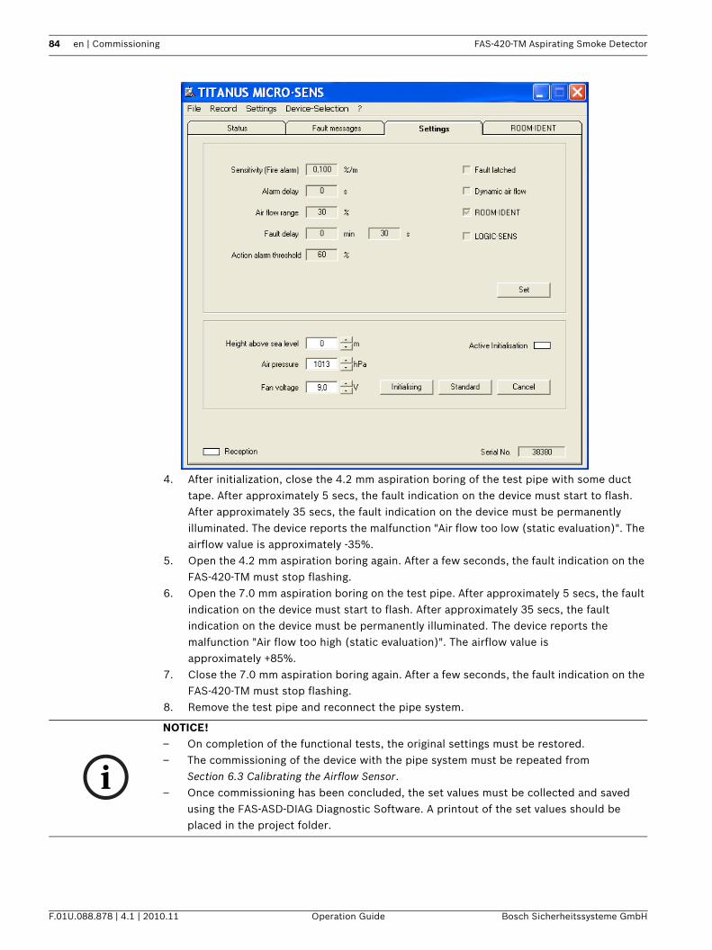
84 en | Commissioning FAS-420-TM Aspirating Smoke Detector
F.01U.088.878 | 4.1 | 2010.11 Operation Guide Bosch Sicherheitssysteme GmbH
4. After initialization, close the 4.2 mm aspiration boring of the test pipe with some duct tape. After approximately 5 secs, the fault indication on the device must start to flash. After approximately 35 secs, the fault indication on the device must be permanently illuminated. The device reports the malfunction "Air flow too low (static evaluation)". The airflow value is approximately -35%.
5. Open the 4.2 mm aspiration boring again. After a few seconds, the fault indication on the FAS-420-TM must stop flashing.
6. Open the 7.0 mm aspiration boring on the test pipe. After approximately 5 secs, the fault indication on the device must start to flash. After approximately 35 secs, the fault indication on the device must be permanently illuminated. The device reports the malfunction "Air flow too high (static evaluation)". The airflow value is approximately +85%.
7. Close the 7.0 mm aspiration boring again. After a few seconds, the fault indication on the FAS-420-TM must stop flashing.
8. Remove the test pipe and reconnect the pipe system.
NOTICE! – On completion of the functional tests, the original settings must be restored.– The commissioning of the device with the pipe system must be repeated from
Section 6.3 Calibrating the Airflow Sensor.– Once commissioning has been concluded, the set values must be collected and saved
using the FAS-ASD-DIAG Diagnostic Software. A printout of the set values should be placed in the project folder.
FAS-420-TM Aspirating Smoke Detector Commissioning | en 85
Bosch Sicherheitssysteme GmbH Operation Guide F.01U.088.878 | 4.1 | 2010.11
6.8 Fire Source Identification CommissioningFire source identification is set using the FAS-ASD-DIAG Diagnostic Software via the "ROOM·IDENT" screen.1. Click the [Train] button. This opens the view with adjustable values used to determine
the transport times for fire source identification in areas A-E.
2. First enter the number of air sampling openings.3. Then enter the blowing out time and voltage of the blowing out and aspiration fan.
You can access the Help function by clicking the question mark to the right of the relevant setting.
4. Click the appropriate aspiration point (A-E) for which the transport time is to be determined.
5. Enter the preselection time necessary to reach the aspiration point and supply the smoke. Once the selected preselection time has expired, the appropriate smoke aspiration point must be charged with smoke. Once the preselection time has expired, the smoke must be available at the aspiration point for another 10 to 15 seconds.
6. Using the smoke level, check that there is no smoke in the aspiration pipe.7. Click the [Start] button. The FAS-420-TM-R/-RVB switches to the aspiration pipe blowing
out. The display of the aspiration point concerned is yellow.8. Once the preselection time has expired, switch the FAS-420-TM-R/-RVB to aspiration. The
smoke must now be available at the selected aspiration point. The smoke level will display if smoke is detected by the FAS-420-TM-R/-RVB. The display of the selected aspiration point turns green and the determined time is entered. Teaching mode for the selected aspiration point is exited.
NOTICE! The commissioning of the fire source identification does not make any distinction between the "ROOM·IDENT" function and the “Fire alarm after ROOM IDENT" function.
86 en | Maintenance FAS-420-TM Aspirating Smoke Detector
F.01U.088.878 | 4.1 | 2010.11 Operation Guide Bosch Sicherheitssysteme GmbH
7 Maintenance
7.1 Visual checkCheck whether…– The pipe system is securely installed and undamaged (where freely accessible)– The air sampling openings of the pipe system are free– The aspiration pipe and connection cable are securely connected– The FAS-420-TM is undamaged.
7.2 Detector Module and Alarm TransferProceed in accordance with Section 6.4 Checking the Detector Module and Alarm Transfer, page 79. Also check the detector module visually for exterior contamination or damage and replace it if necessary.
7.3 Pipe SystemCheck the pipe system and the air sampling openings for obstruction in areas susceptible to dust particles or icing. If necessary, blow out the pipe system and air sampling openings with blast air. Use a mobile cylinder of compressed air (blowing-out system) or activate the manual blowing-out system located on site. The components (compressors, compressed air containers, dryers) required to supply the compressed air can be obtained directly from the relevant compressed air system suppliers.
NOTICE! A hardware defect in the detector module is displayed in the "Fault messages" screen of the diagnostic software.
CAUTION! Before blowing out the pipe system, disconnect the FAS-420-TM from the pipe system; otherwise, the airflow sensor will be damaged.
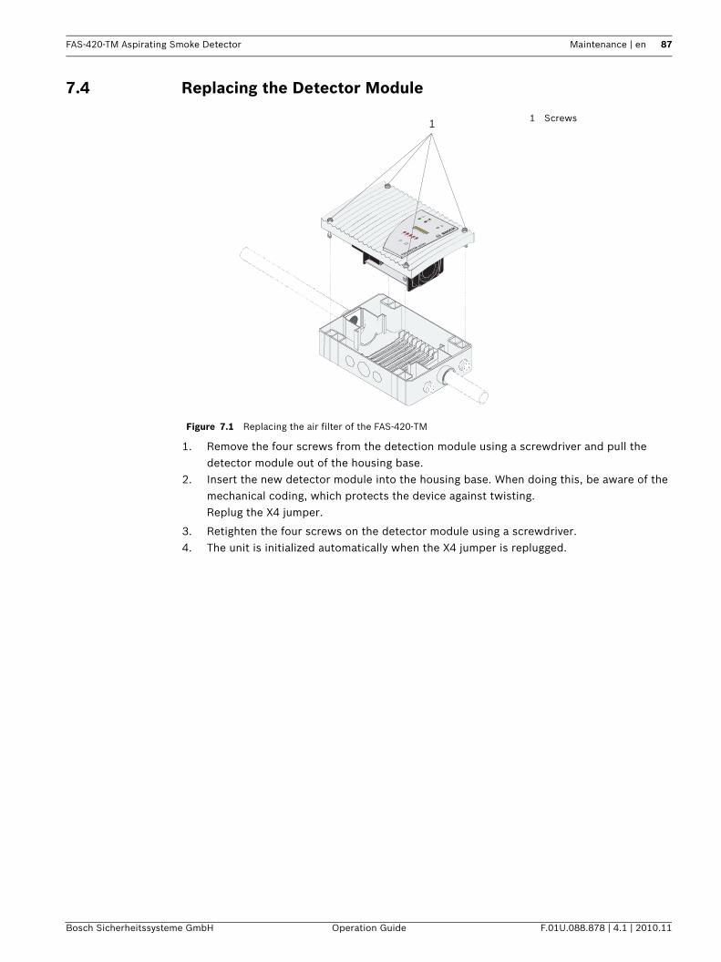
FAS-420-TM Aspirating Smoke Detector Maintenance | en 87
Bosch Sicherheitssysteme GmbH Operation Guide F.01U.088.878 | 4.1 | 2010.11
7.4 Replacing the Detector Module
1. Remove the four screws from the detection module using a screwdriver and pull the detector module out of the housing base.
2. Insert the new detector module into the housing base. When doing this, be aware of the mechanical coding, which protects the device against twisting.Replug the X4 jumper.
3. Retighten the four screws on the detector module using a screwdriver.4. The unit is initialized automatically when the X4 jumper is replugged.
Figure 7.1 Replacing the air filter of the FAS-420-TM
1 Screws
FAS-420-TM series
1
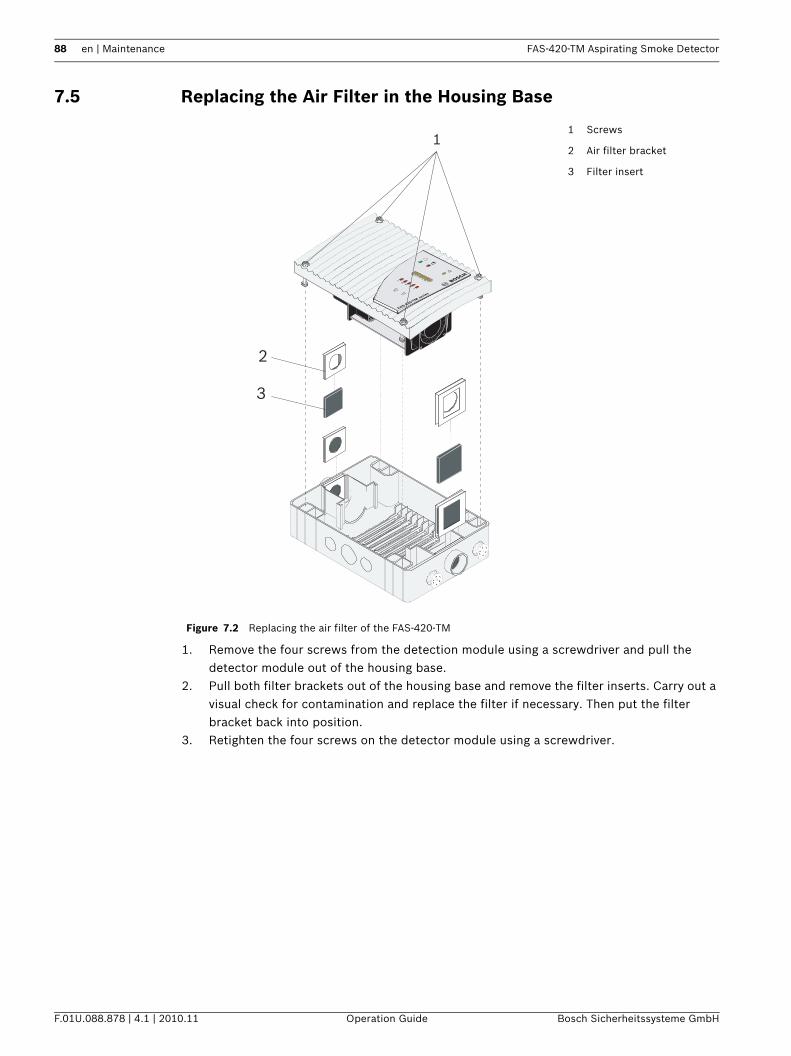
88 en | Maintenance FAS-420-TM Aspirating Smoke Detector
F.01U.088.878 | 4.1 | 2010.11 Operation Guide Bosch Sicherheitssysteme GmbH
7.5 Replacing the Air Filter in the Housing Base
1. Remove the four screws from the detection module using a screwdriver and pull the detector module out of the housing base.
2. Pull both filter brackets out of the housing base and remove the filter inserts. Carry out a visual check for contamination and replace the filter if necessary. Then put the filter bracket back into position.
3. Retighten the four screws on the detector module using a screwdriver.
Figure 7.2 Replacing the air filter of the FAS-420-TM
1 Screws
2 Air filter bracket
3 Filter insert
FAS-420-TM series
1
2
3
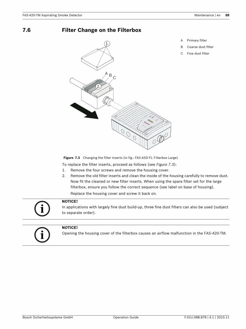
FAS-420-TM Aspirating Smoke Detector Maintenance | en 89
Bosch Sicherheitssysteme GmbH Operation Guide F.01U.088.878 | 4.1 | 2010.11
7.6 Filter Change on the Filterbox
To replace the filter inserts, proceed as follows (see Figure 7.3):1. Remove the four screws and remove the housing cover.2. Remove the old filter inserts and clean the inside of the housing carefully to remove dust.
Now fit the cleaned or new filter inserts. When using the spare filter set for the large filterbox, ensure you follow the correct sequence (see label on base of housing).
Replace the housing cover and screw it back on.
Figure 7.3 Changing the filter inserts (in fig.: FAS-ASD-FL Filterbox Large)
A Primary filter
B Coarse dust filter
C Fine dust filter
1.
2.
A B C
FAS-420-TM serie
s
NOTICE! In applications with largely fine dust build-up, three fine dust filters can also be used (subject to separate order).
NOTICE! Opening the housing cover of the filterbox causes an airflow malfunction in the FAS-420-TM.
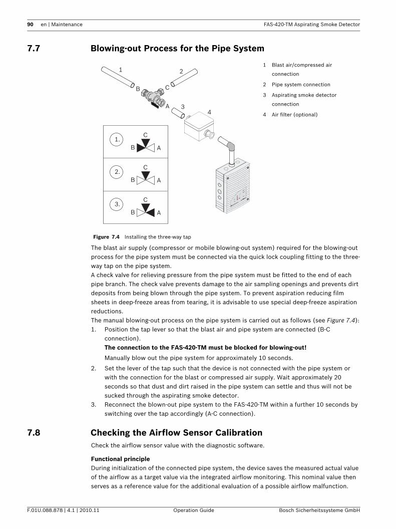
90 en | Maintenance FAS-420-TM Aspirating Smoke Detector
F.01U.088.878 | 4.1 | 2010.11 Operation Guide Bosch Sicherheitssysteme GmbH
7.7 Blowing-out Process for the Pipe System
The blast air supply (compressor or mobile blowing-out system) required for the blowing-out process for the pipe system must be connected via the quick lock coupling fitting to the three-way tap on the pipe system.A check valve for relieving pressure from the pipe system must be fitted to the end of each pipe branch. The check valve prevents damage to the air sampling openings and prevents dirt deposits from being blown through the pipe system. To prevent aspiration reducing film sheets in deep-freeze areas from tearing, it is advisable to use special deep-freeze aspiration reductions.The manual blowing-out process on the pipe system is carried out as follows (see Figure 7.4):1. Position the tap lever so that the blast air and pipe system are connected (B-C
connection).The connection to the FAS-420-TM must be blocked for blowing-out!
Manually blow out the pipe system for approximately 10 seconds.
2. Set the lever of the tap such that the device is not connected with the pipe system or with the connection for the blast or compressed air supply. Wait approximately 20 seconds so that dust and dirt raised in the pipe system can settle and thus will not be sucked through the aspirating smoke detector.
3. Reconnect the blown-out pipe system to the FAS-420-TM within a further 10 seconds by switching over the tap accordingly (A-C connection).
7.8 Checking the Airflow Sensor CalibrationCheck the airflow sensor value with the diagnostic software.
Functional principleDuring initialization of the connected pipe system, the device saves the measured actual value of the airflow as a target value via the integrated airflow monitoring. This nominal value then serves as a reference value for the additional evaluation of a possible airflow malfunction.
Figure 7.4 Installing the three-way tap
1 Blast air/compressed air
connection
2 Pipe system connection
3 Aspirating smoke detector
connection
4 Air filter (optional)
FAS-420-TM serie
s
A
B C
1 2
34
AB
C2.
AB
C3.
AB
C1.
FAS-420-TM Aspirating Smoke Detector Maintenance | en 91
Bosch Sicherheitssysteme GmbH Operation Guide F.01U.088.878 | 4.1 | 2010.11
Depending on the airflow threshold selected (see "Adapting the airflow sensitivity" in Section 3.3 Airflow Monitoring, page 36), the current airflow value during operation can fluctuate around this target value without triggering an airflow malfunction. Only if the selected airflow threshold is exceeded will the airflow malfunction be reported by the device and thus transmitted.
Checking the actual valueThe tolerance range of the selected airflow threshold and the actual and target values are represented in the diagnostic software. The limits correspond to the airflow range set.Check the deviation of the actual value from the target value. If there is a deviation of > ±3/4 of the set threshold, you should check the pipe system carefully (see below: Section Troubleshooting airflow malfunction).
Dependent on air pressureTo ensure long-term fault-free operation of the device, the airflow sensor must be calibrated depending on the air pressure (see Section 6.3.2 Air-Pressure-Dependent Calibration, page 77). Only with this type of calibration do low air pressure fluctuations remain within the monitoring window and thus in the permissible tolerance range.
Independent of air pressureIf the sensor calibration is carried out independently of air pressure, fluctuations in the air pressure can cause undesired airflow malfunctions. If the change in airflow is greater than 30%, the calibration of the airflow sensor can be carried out independently of the air pressure; it must then be ensured that no fluctuations in air pressure can occur in the immediate environment.
Troubleshooting airflow malfunctionIf the airflow calibration has been carried out depending on air pressure and the actual value still does not lie within the tolerance range of the selected airflow threshold (airflow malfunction displayed on the device), then a further disturbance value in addition to air pressure or temperature fluctuation exists.
1. In this case, check the pipe system for leaks and obstructions (see Section 6.6 Checking Airflow Monitoring, page 80, "Troubleshooting").
NOTICE! The current airflow value may deviate from the target value not only due to a malfunction of the pipe system (break or obstruction), but also due to fluctuations in the air pressure in the environment.
CAUTION! If the airflow change is set at less than 30%, an air-pressure-dependent calibration must be carried out.
CAUTION! If air pressure fluctuations are anticipated in the immediate environment, the airflow sensor has to be calibrated in dependence of air pressure (see also Section 3.3 Airflow Monitoring, page 36).
CAUTION! In case of a defect in the airflow monitoring, only authorized personnel may replace the detector module!
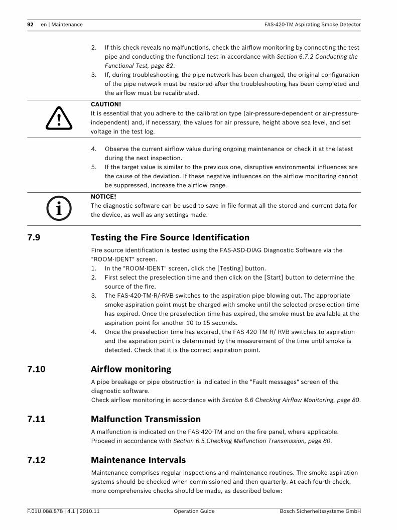
92 en | Maintenance FAS-420-TM Aspirating Smoke Detector
F.01U.088.878 | 4.1 | 2010.11 Operation Guide Bosch Sicherheitssysteme GmbH
2. If this check reveals no malfunctions, check the airflow monitoring by connecting the test pipe and conducting the functional test in accordance with Section 6.7.2 Conducting the Functional Test, page 82.
3. If, during troubleshooting, the pipe network has been changed, the original configuration of the pipe network must be restored after the troubleshooting has been completed and the airflow must be recalibrated.
4. Observe the current airflow value during ongoing maintenance or check it at the latest during the next inspection.
5. If the target value is similar to the previous one, disruptive environmental influences are the cause of the deviation. If these negative influences on the airflow monitoring cannot be suppressed, increase the airflow range.
7.9 Testing the Fire Source IdentificationFire source identification is tested using the FAS-ASD-DIAG Diagnostic Software via the "ROOM·IDENT" screen.1. In the "ROOM·IDENT" screen, click the [Testing] button.2. First select the preselection time and then click on the [Start] button to determine the
source of the fire.3. The FAS-420-TM-R/-RVB switches to the aspiration pipe blowing out. The appropriate
smoke aspiration point must be charged with smoke until the selected preselection time has expired. Once the preselection time has expired, the smoke must be available at the aspiration point for another 10 to 15 seconds.
4. Once the preselection time has expired, the FAS-420-TM-R/-RVB switches to aspiration and the aspiration point is determined by the measurement of the time until smoke is detected. Check that it is the correct aspiration point.
7.10 Airflow monitoringA pipe breakage or pipe obstruction is indicated in the "Fault messages" screen of the diagnostic software.Check airflow monitoring in accordance with Section 6.6 Checking Airflow Monitoring, page 80.
7.11 Malfunction TransmissionA malfunction is indicated on the FAS-420-TM and on the fire panel, where applicable.Proceed in accordance with Section 6.5 Checking Malfunction Transmission, page 80.
7.12 Maintenance IntervalsMaintenance comprises regular inspections and maintenance routines. The smoke aspiration systems should be checked when commissioned and then quarterly. At each fourth check, more comprehensive checks should be made, as described below:
CAUTION! It is essential that you adhere to the calibration type (air-pressure-dependent or air-pressure-independent) and, if necessary, the values for air pressure, height above sea level, and set voltage in the test log.
NOTICE! The diagnostic software can be used to save in file format all the stored and current data for the device, as well as any settings made.
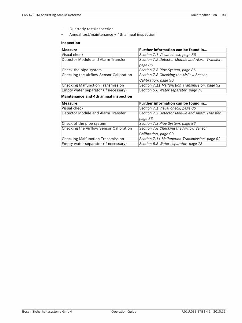
FAS-420-TM Aspirating Smoke Detector Maintenance | en 93
Bosch Sicherheitssysteme GmbH Operation Guide F.01U.088.878 | 4.1 | 2010.11
– Quarterly test/inspection– Annual test/maintenance + 4th annual inspection
Inspection
Maintenance and 4th annual inspection
Measure Further information can be found in...Visual check Section 7.1 Visual check, page 86Detector Module and Alarm Transfer Section 7.2 Detector Module and Alarm Transfer,
page 86Check the pipe system Section 7.3 Pipe System, page 86Checking the Airflow Sensor Calibration Section 7.8 Checking the Airflow Sensor
Calibration, page 90Checking Malfunction Transmission Section 7.11 Malfunction Transmission, page 92Empty water separator (if necessary) Section 5.8 Water separator, page 73
Measure Further information can be found in...Visual check Section 7.1 Visual check, page 86Detector Module and Alarm Transfer Section 7.2 Detector Module and Alarm Transfer,
page 86Check of the pipe system Section 7.3 Pipe System, page 86Checking the Airflow Sensor Calibration Section 7.8 Checking the Airflow Sensor
Calibration, page 90Checking Malfunction Transmission Section 7.11 Malfunction Transmission, page 92Empty water separator (if necessary) Section 5.8 Water separator, page 73

94 en | Appendix FAS-420-TM Aspirating Smoke Detector
F.01U.088.878 | 4.1 | 2010.11 Operation Guide Bosch Sicherheitssysteme GmbH
8 AppendixAll the permitted detector addresses are indicated in Section 8.1 DIP Switch Settings for Detector Addresses. See also Section 4.2 Setting the Detector Address, page 58. The form in Section 8.4 Test Log for Aspirating Smoke Detectors in the FAS-420-TM Series is required for commissioning (see Section 6 Commissioning, page 76 et seqq).
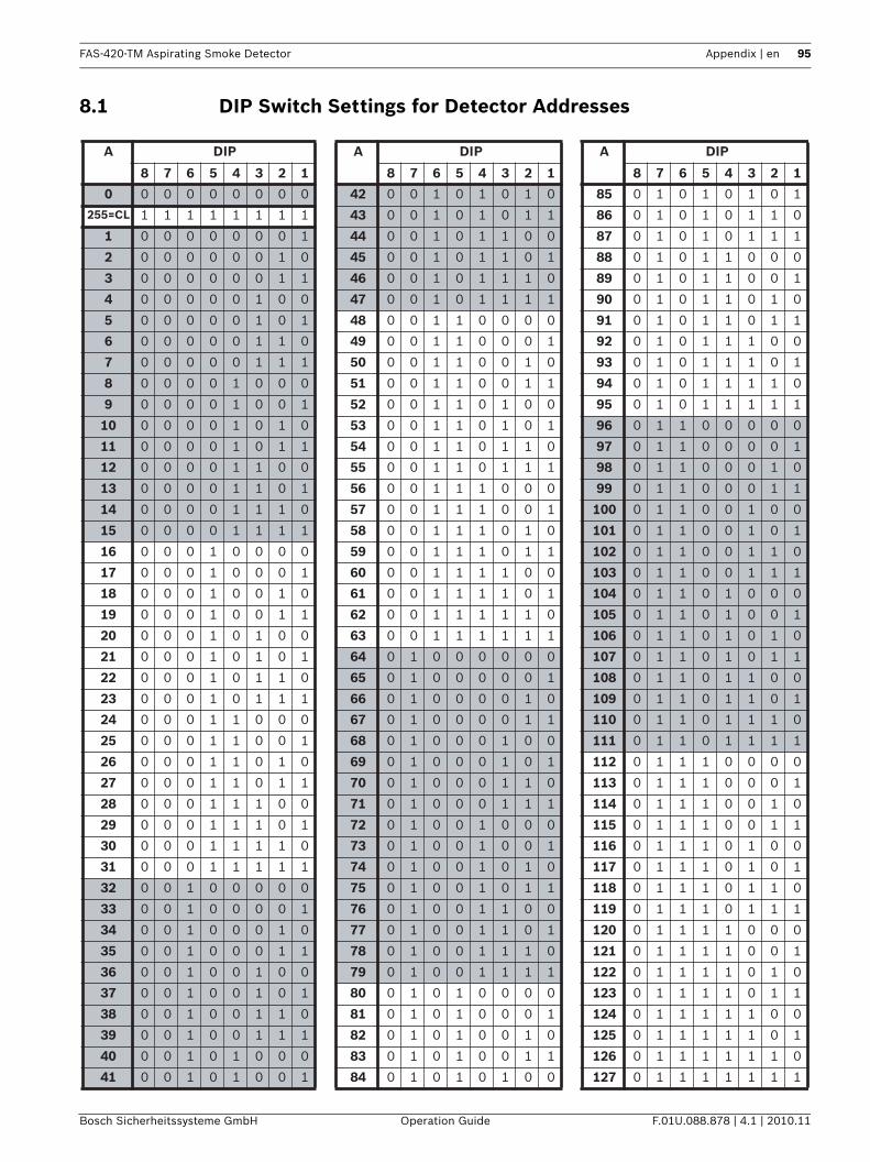
FAS-420-TM Aspirating Smoke Detector Appendix | en 95
Bosch Sicherheitssysteme GmbH Operation Guide F.01U.088.878 | 4.1 | 2010.11
8.1 DIP Switch Settings for Detector Addresses
A DIP A DIP A DIP
8 7 6 5 4 3 2 1 8 7 6 5 4 3 2 1 8 7 6 5 4 3 2 1
0 0 0 0 0 0 0 0 0 42 0 0 1 0 1 0 1 0 85 0 1 0 1 0 1 0 1
255=CL 1 1 1 1 1 1 1 1 43 0 0 1 0 1 0 1 1 86 0 1 0 1 0 1 1 0
1 0 0 0 0 0 0 0 1 44 0 0 1 0 1 1 0 0 87 0 1 0 1 0 1 1 1
2 0 0 0 0 0 0 1 0 45 0 0 1 0 1 1 0 1 88 0 1 0 1 1 0 0 0
3 0 0 0 0 0 0 1 1 46 0 0 1 0 1 1 1 0 89 0 1 0 1 1 0 0 1
4 0 0 0 0 0 1 0 0 47 0 0 1 0 1 1 1 1 90 0 1 0 1 1 0 1 0
5 0 0 0 0 0 1 0 1 48 0 0 1 1 0 0 0 0 91 0 1 0 1 1 0 1 1
6 0 0 0 0 0 1 1 0 49 0 0 1 1 0 0 0 1 92 0 1 0 1 1 1 0 0
7 0 0 0 0 0 1 1 1 50 0 0 1 1 0 0 1 0 93 0 1 0 1 1 1 0 1
8 0 0 0 0 1 0 0 0 51 0 0 1 1 0 0 1 1 94 0 1 0 1 1 1 1 0
9 0 0 0 0 1 0 0 1 52 0 0 1 1 0 1 0 0 95 0 1 0 1 1 1 1 1
10 0 0 0 0 1 0 1 0 53 0 0 1 1 0 1 0 1 96 0 1 1 0 0 0 0 0
11 0 0 0 0 1 0 1 1 54 0 0 1 1 0 1 1 0 97 0 1 1 0 0 0 0 1
12 0 0 0 0 1 1 0 0 55 0 0 1 1 0 1 1 1 98 0 1 1 0 0 0 1 0
13 0 0 0 0 1 1 0 1 56 0 0 1 1 1 0 0 0 99 0 1 1 0 0 0 1 1
14 0 0 0 0 1 1 1 0 57 0 0 1 1 1 0 0 1 100 0 1 1 0 0 1 0 0
15 0 0 0 0 1 1 1 1 58 0 0 1 1 1 0 1 0 101 0 1 1 0 0 1 0 1
16 0 0 0 1 0 0 0 0 59 0 0 1 1 1 0 1 1 102 0 1 1 0 0 1 1 0
17 0 0 0 1 0 0 0 1 60 0 0 1 1 1 1 0 0 103 0 1 1 0 0 1 1 1
18 0 0 0 1 0 0 1 0 61 0 0 1 1 1 1 0 1 104 0 1 1 0 1 0 0 0
19 0 0 0 1 0 0 1 1 62 0 0 1 1 1 1 1 0 105 0 1 1 0 1 0 0 1
20 0 0 0 1 0 1 0 0 63 0 0 1 1 1 1 1 1 106 0 1 1 0 1 0 1 0
21 0 0 0 1 0 1 0 1 64 0 1 0 0 0 0 0 0 107 0 1 1 0 1 0 1 1
22 0 0 0 1 0 1 1 0 65 0 1 0 0 0 0 0 1 108 0 1 1 0 1 1 0 0
23 0 0 0 1 0 1 1 1 66 0 1 0 0 0 0 1 0 109 0 1 1 0 1 1 0 1
24 0 0 0 1 1 0 0 0 67 0 1 0 0 0 0 1 1 110 0 1 1 0 1 1 1 0
25 0 0 0 1 1 0 0 1 68 0 1 0 0 0 1 0 0 111 0 1 1 0 1 1 1 1
26 0 0 0 1 1 0 1 0 69 0 1 0 0 0 1 0 1 112 0 1 1 1 0 0 0 0
27 0 0 0 1 1 0 1 1 70 0 1 0 0 0 1 1 0 113 0 1 1 1 0 0 0 1
28 0 0 0 1 1 1 0 0 71 0 1 0 0 0 1 1 1 114 0 1 1 1 0 0 1 0
29 0 0 0 1 1 1 0 1 72 0 1 0 0 1 0 0 0 115 0 1 1 1 0 0 1 1
30 0 0 0 1 1 1 1 0 73 0 1 0 0 1 0 0 1 116 0 1 1 1 0 1 0 0
31 0 0 0 1 1 1 1 1 74 0 1 0 0 1 0 1 0 117 0 1 1 1 0 1 0 1
32 0 0 1 0 0 0 0 0 75 0 1 0 0 1 0 1 1 118 0 1 1 1 0 1 1 0
33 0 0 1 0 0 0 0 1 76 0 1 0 0 1 1 0 0 119 0 1 1 1 0 1 1 1
34 0 0 1 0 0 0 1 0 77 0 1 0 0 1 1 0 1 120 0 1 1 1 1 0 0 0
35 0 0 1 0 0 0 1 1 78 0 1 0 0 1 1 1 0 121 0 1 1 1 1 0 0 1
36 0 0 1 0 0 1 0 0 79 0 1 0 0 1 1 1 1 122 0 1 1 1 1 0 1 0
37 0 0 1 0 0 1 0 1 80 0 1 0 1 0 0 0 0 123 0 1 1 1 1 0 1 1
38 0 0 1 0 0 1 1 0 81 0 1 0 1 0 0 0 1 124 0 1 1 1 1 1 0 0
39 0 0 1 0 0 1 1 1 82 0 1 0 1 0 0 1 0 125 0 1 1 1 1 1 0 1
40 0 0 1 0 1 0 0 0 83 0 1 0 1 0 0 1 1 126 0 1 1 1 1 1 1 0
41 0 0 1 0 1 0 0 1 84 0 1 0 1 0 1 0 0 127 0 1 1 1 1 1 1 1
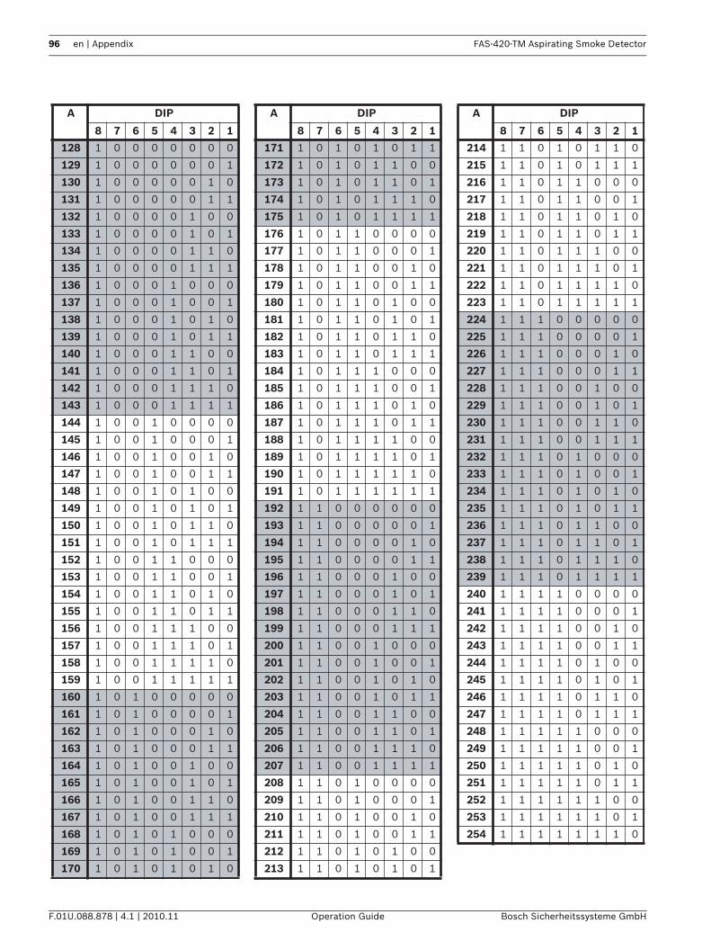
96 en | Appendix FAS-420-TM Aspirating Smoke Detector
F.01U.088.878 | 4.1 | 2010.11 Operation Guide Bosch Sicherheitssysteme GmbH
A DIP A DIP A DIP
8 7 6 5 4 3 2 1 8 7 6 5 4 3 2 1 8 7 6 5 4 3 2 1
128 1 0 0 0 0 0 0 0 171 1 0 1 0 1 0 1 1 214 1 1 0 1 0 1 1 0
129 1 0 0 0 0 0 0 1 172 1 0 1 0 1 1 0 0 215 1 1 0 1 0 1 1 1
130 1 0 0 0 0 0 1 0 173 1 0 1 0 1 1 0 1 216 1 1 0 1 1 0 0 0
131 1 0 0 0 0 0 1 1 174 1 0 1 0 1 1 1 0 217 1 1 0 1 1 0 0 1
132 1 0 0 0 0 1 0 0 175 1 0 1 0 1 1 1 1 218 1 1 0 1 1 0 1 0
133 1 0 0 0 0 1 0 1 176 1 0 1 1 0 0 0 0 219 1 1 0 1 1 0 1 1
134 1 0 0 0 0 1 1 0 177 1 0 1 1 0 0 0 1 220 1 1 0 1 1 1 0 0
135 1 0 0 0 0 1 1 1 178 1 0 1 1 0 0 1 0 221 1 1 0 1 1 1 0 1
136 1 0 0 0 1 0 0 0 179 1 0 1 1 0 0 1 1 222 1 1 0 1 1 1 1 0
137 1 0 0 0 1 0 0 1 180 1 0 1 1 0 1 0 0 223 1 1 0 1 1 1 1 1
138 1 0 0 0 1 0 1 0 181 1 0 1 1 0 1 0 1 224 1 1 1 0 0 0 0 0
139 1 0 0 0 1 0 1 1 182 1 0 1 1 0 1 1 0 225 1 1 1 0 0 0 0 1
140 1 0 0 0 1 1 0 0 183 1 0 1 1 0 1 1 1 226 1 1 1 0 0 0 1 0
141 1 0 0 0 1 1 0 1 184 1 0 1 1 1 0 0 0 227 1 1 1 0 0 0 1 1
142 1 0 0 0 1 1 1 0 185 1 0 1 1 1 0 0 1 228 1 1 1 0 0 1 0 0
143 1 0 0 0 1 1 1 1 186 1 0 1 1 1 0 1 0 229 1 1 1 0 0 1 0 1
144 1 0 0 1 0 0 0 0 187 1 0 1 1 1 0 1 1 230 1 1 1 0 0 1 1 0
145 1 0 0 1 0 0 0 1 188 1 0 1 1 1 1 0 0 231 1 1 1 0 0 1 1 1
146 1 0 0 1 0 0 1 0 189 1 0 1 1 1 1 0 1 232 1 1 1 0 1 0 0 0
147 1 0 0 1 0 0 1 1 190 1 0 1 1 1 1 1 0 233 1 1 1 0 1 0 0 1
148 1 0 0 1 0 1 0 0 191 1 0 1 1 1 1 1 1 234 1 1 1 0 1 0 1 0
149 1 0 0 1 0 1 0 1 192 1 1 0 0 0 0 0 0 235 1 1 1 0 1 0 1 1
150 1 0 0 1 0 1 1 0 193 1 1 0 0 0 0 0 1 236 1 1 1 0 1 1 0 0
151 1 0 0 1 0 1 1 1 194 1 1 0 0 0 0 1 0 237 1 1 1 0 1 1 0 1
152 1 0 0 1 1 0 0 0 195 1 1 0 0 0 0 1 1 238 1 1 1 0 1 1 1 0
153 1 0 0 1 1 0 0 1 196 1 1 0 0 0 1 0 0 239 1 1 1 0 1 1 1 1
154 1 0 0 1 1 0 1 0 197 1 1 0 0 0 1 0 1 240 1 1 1 1 0 0 0 0
155 1 0 0 1 1 0 1 1 198 1 1 0 0 0 1 1 0 241 1 1 1 1 0 0 0 1
156 1 0 0 1 1 1 0 0 199 1 1 0 0 0 1 1 1 242 1 1 1 1 0 0 1 0
157 1 0 0 1 1 1 0 1 200 1 1 0 0 1 0 0 0 243 1 1 1 1 0 0 1 1
158 1 0 0 1 1 1 1 0 201 1 1 0 0 1 0 0 1 244 1 1 1 1 0 1 0 0
159 1 0 0 1 1 1 1 1 202 1 1 0 0 1 0 1 0 245 1 1 1 1 0 1 0 1
160 1 0 1 0 0 0 0 0 203 1 1 0 0 1 0 1 1 246 1 1 1 1 0 1 1 0
161 1 0 1 0 0 0 0 1 204 1 1 0 0 1 1 0 0 247 1 1 1 1 0 1 1 1
162 1 0 1 0 0 0 1 0 205 1 1 0 0 1 1 0 1 248 1 1 1 1 1 0 0 0
163 1 0 1 0 0 0 1 1 206 1 1 0 0 1 1 1 0 249 1 1 1 1 1 0 0 1
164 1 0 1 0 0 1 0 0 207 1 1 0 0 1 1 1 1 250 1 1 1 1 1 0 1 0
165 1 0 1 0 0 1 0 1 208 1 1 0 1 0 0 0 0 251 1 1 1 1 1 0 1 1
166 1 0 1 0 0 1 1 0 209 1 1 0 1 0 0 0 1 252 1 1 1 1 1 1 0 0
167 1 0 1 0 0 1 1 1 210 1 1 0 1 0 0 1 0 253 1 1 1 1 1 1 0 1
168 1 0 1 0 1 0 0 0 211 1 1 0 1 0 0 1 1 254 1 1 1 1 1 1 1 0
169 1 0 1 0 1 0 0 1 212 1 1 0 1 0 1 0 0
170 1 0 1 0 1 0 1 0 213 1 1 0 1 0 1 0 1
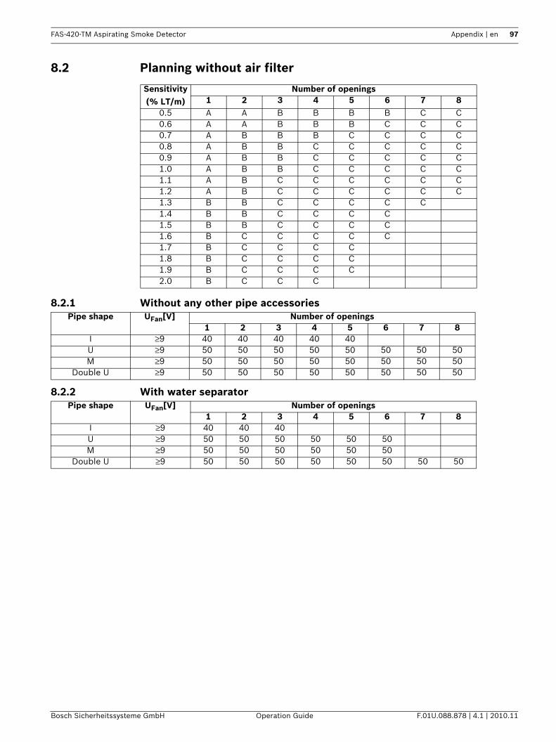
FAS-420-TM Aspirating Smoke Detector Appendix | en 97
Bosch Sicherheitssysteme GmbH Operation Guide F.01U.088.878 | 4.1 | 2010.11
8.2 Planning without air filter
8.2.1 Without any other pipe accessories
8.2.2 With water separator
Sensitivity (% LT/m)
Number of openings1 2 3 4 5 6 7 8
0.5 A A B B B B C C0.6 A A B B B C C C0.7 A B B B C C C C0.8 A B B C C C C C0.9 A B B C C C C C1.0 A B B C C C C C1.1 A B C C C C C C1.2 A B C C C C C C1.3 B B C C C C C1.4 B B C C C C1.5 B B C C C C1.6 B C C C C C1.7 B C C C C1.8 B C C C C1.9 B C C C C2.0 B C C C
Pipe shape UFan[V] Number of openings1 2 3 4 5 6 7 8
I ≥9 40 40 40 40 40U ≥9 50 50 50 50 50 50 50 50M ≥9 50 50 50 50 50 50 50 50
Double U ≥9 50 50 50 50 50 50 50 50
Pipe shape UFan[V] Number of openings1 2 3 4 5 6 7 8
I ≥9 40 40 40U ≥9 50 50 50 50 50 50M ≥9 50 50 50 50 50 50
Double U ≥9 50 50 50 50 50 50 50 50
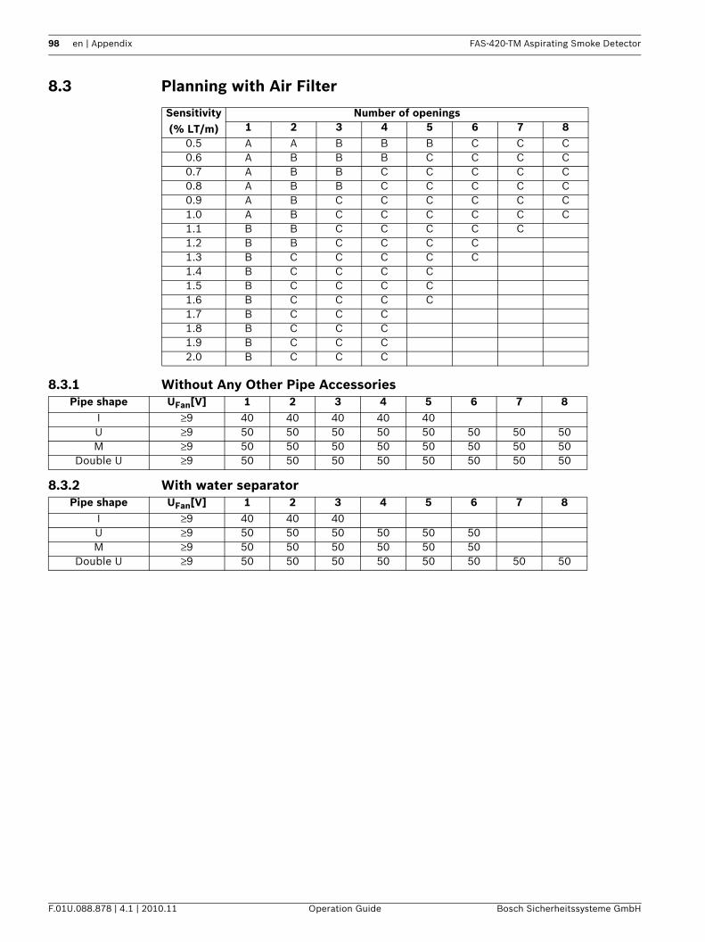
98 en | Appendix FAS-420-TM Aspirating Smoke Detector
F.01U.088.878 | 4.1 | 2010.11 Operation Guide Bosch Sicherheitssysteme GmbH
8.3 Planning with Air Filter
8.3.1 Without Any Other Pipe Accessories
8.3.2 With water separator
Sensitivity (% LT/m)
Number of openings1 2 3 4 5 6 7 8
0.5 A A B B B C C C0.6 A B B B C C C C0.7 A B B C C C C C0.8 A B B C C C C C0.9 A B C C C C C C1.0 A B C C C C C C1.1 B B C C C C C1.2 B B C C C C1.3 B C C C C C1.4 B C C C C1.5 B C C C C1.6 B C C C C1.7 B C C C1.8 B C C C1.9 B C C C2.0 B C C C
Pipe shape UFan[V] 1 2 3 4 5 6 7 8I ≥9 40 40 40 40 40U ≥9 50 50 50 50 50 50 50 50M ≥9 50 50 50 50 50 50 50 50
Double U ≥9 50 50 50 50 50 50 50 50
Pipe shape UFan[V] 1 2 3 4 5 6 7 8I ≥9 40 40 40U ≥9 50 50 50 50 50 50M ≥9 50 50 50 50 50 50
Double U ≥9 50 50 50 50 50 50 50 50
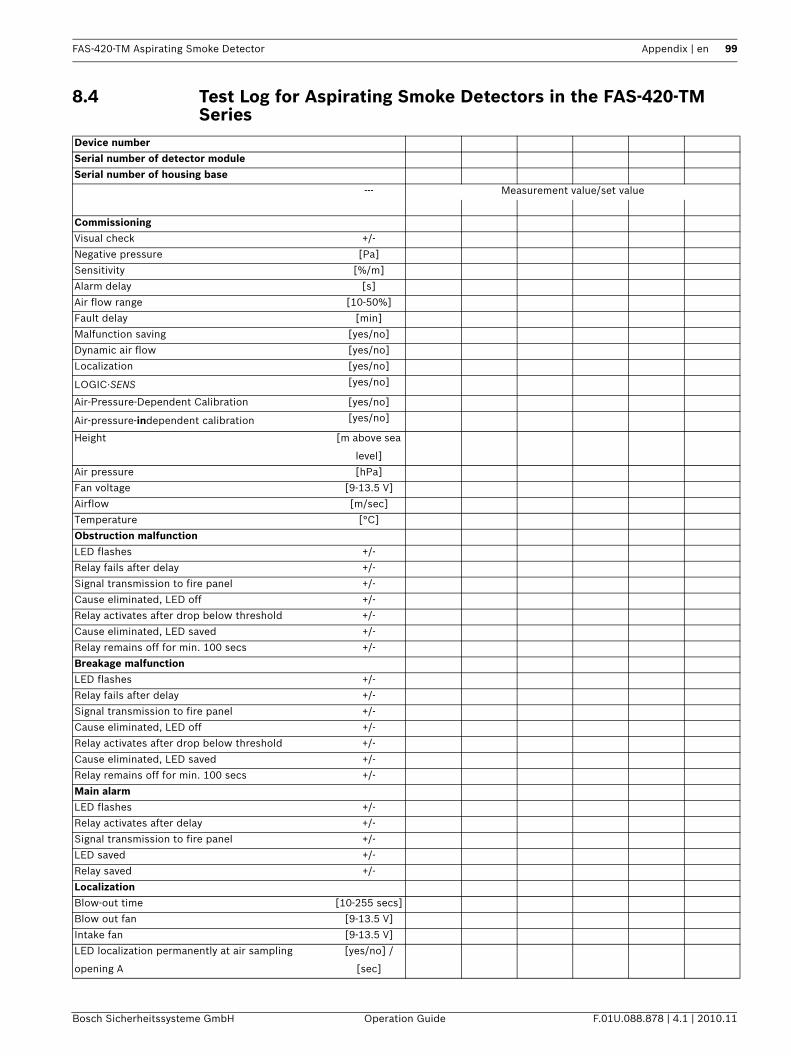
FAS-420-TM Aspirating Smoke Detector Appendix | en 99
Bosch Sicherheitssysteme GmbH Operation Guide F.01U.088.878 | 4.1 | 2010.11
8.4 Test Log for Aspirating Smoke Detectors in the FAS-420-TM Series
Device numberSerial number of detector moduleSerial number of housing base
--- Measurement value/set value
CommissioningVisual check +/-
Negative pressure [Pa]
Sensitivity [%/m]
Alarm delay [s]
Air flow range [10-50%]
Fault delay [min]
Malfunction saving [yes/no]
Dynamic air flow [yes/no]
Localization [yes/no]
LOGIC·SENS [yes/no]
Air-Pressure-Dependent Calibration [yes/no]
Air-pressure-independent calibration [yes/no]
Height [m above sea
level]
Air pressure [hPa]
Fan voltage [9-13.5 V]
Airflow [m/sec]
Temperature [°C]
Obstruction malfunctionLED flashes +/-
Relay fails after delay +/-
Signal transmission to fire panel +/-
Cause eliminated, LED off +/-
Relay activates after drop below threshold +/-
Cause eliminated, LED saved +/-
Relay remains off for min. 100 secs +/-
Breakage malfunctionLED flashes +/-
Relay fails after delay +/-
Signal transmission to fire panel +/-
Cause eliminated, LED off +/-
Relay activates after drop below threshold +/-
Cause eliminated, LED saved +/-
Relay remains off for min. 100 secs +/-
Main alarmLED flashes +/-
Relay activates after delay +/-
Signal transmission to fire panel +/-
LED saved +/-
Relay saved +/-
LocalizationBlow-out time [10-255 secs]
Blow out fan [9-13.5 V]
Intake fan [9-13.5 V]
LED localization permanently at air sampling
opening A
[yes/no] /
[sec]
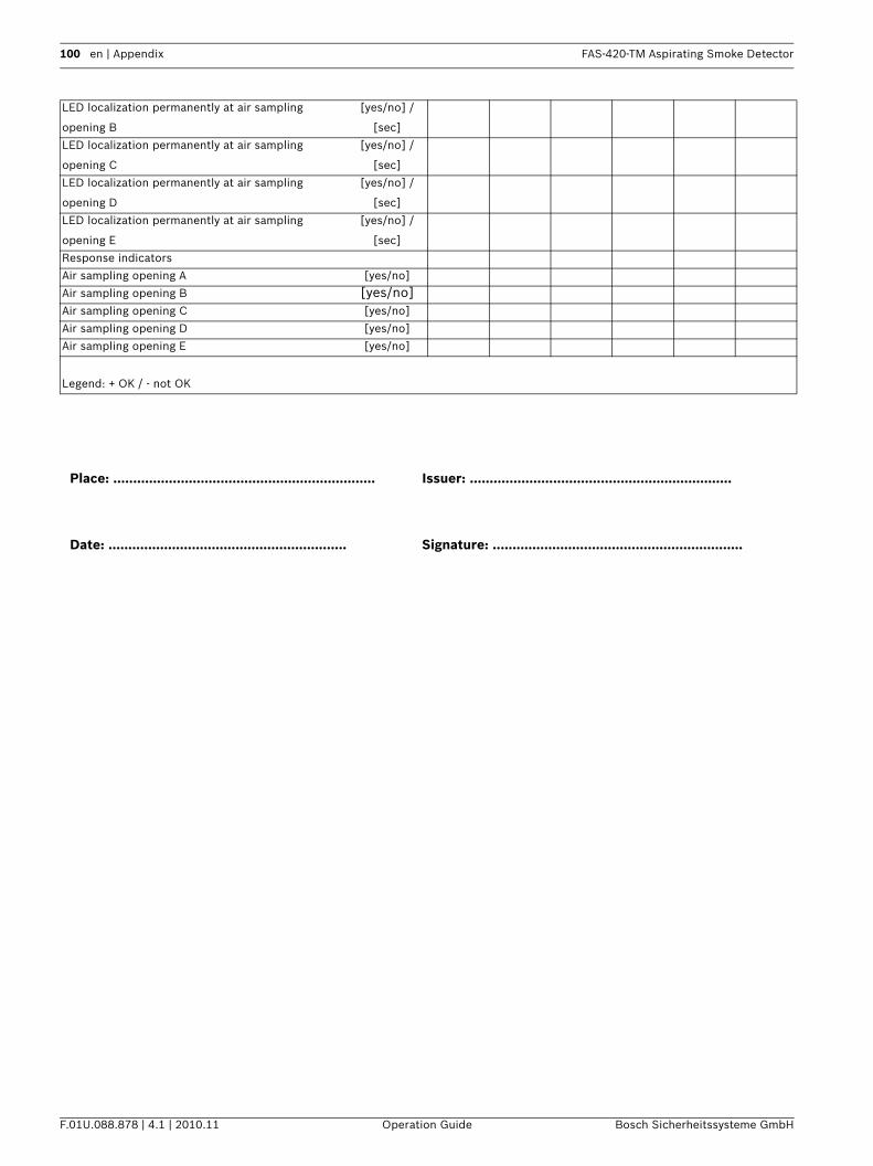
100 en | Appendix FAS-420-TM Aspirating Smoke Detector
F.01U.088.878 | 4.1 | 2010.11 Operation Guide Bosch Sicherheitssysteme GmbH
LED localization permanently at air sampling
opening B
[yes/no] /
[sec]
LED localization permanently at air sampling
opening C
[yes/no] /
[sec]
LED localization permanently at air sampling
opening D
[yes/no] /
[sec]
LED localization permanently at air sampling
opening E
[yes/no] /
[sec]
Response indicators
Air sampling opening A [yes/no]
Air sampling opening B [yes/no]Air sampling opening C [yes/no]
Air sampling opening D [yes/no]
Air sampling opening E [yes/no]
Legend: + OK / - not OK
Place: .................................................................. Issuer: ..................................................................
Date: ............................................................ Signature: ...............................................................
FAS-420-TM Aspirating Smoke Detector Index | en 101
Bosch Sicherheitssysteme GmbH Operation Guide F.01U.088.878 | 4.1 | 2010.11
IndexSymbols"Improved version" LSN mode 58AAir conditioning units 11Air filter 13, 22, 31, 72, 73, 88, 89Air sampling opening 9, 12, 23, 29, 34, 68Air-conditioning duct 11, 52, 53Air-conditioning unit 52, 71Airflow initialization 77, 83Airflow malfunction 80, 81, 89, 91Airflow Monitoring 15Airflow monitoring 8, 36Airflow sensitivity 36Airflow sensor 12, 15, 16, 36Airflow sensors 8Alarm 13, 30Alarm current 56Alarm delay 64, 81Alarm transfer 79, 86Ansaugbohrung 68Ansaugreduzierungsfolie 68Area monitoring 10, 23, 25Aspiration boring 10, 69Aspiration reducing clips 24Aspiration reducing film sheet 9, 23, 29Asymmetrical structure 34BBends 35, 66Blast air 73, 86Blowing out 23, 24Bore distances 72Branch length 34CCalibrating the airflow sensor 16, 77, 90Charging current 55Concealed installation 25Current calculation 55DDelay 13, 15, 16Detector address 58Double U-pipe 35Double U-pipe system - simplified planning 51Double U-pipe system activation thresholds 47, 48Double-U-pipe system for space protection 43, 48Duct cross-section 52, 54EEnd cap 22, 54, 67Equipment monitoring 11, 12, 23, 34FFAS-ASD-DIAG Diagnostic Software 9, 17, 21, 28, 64, 65, 76, 77, 81, 84, 92Fault indication 80, 84Filter change 89Fittings 12, 23, 28, 66Flow resistance 35, 66Flow speed 52Freiblasen 90Functional test 81
HHigh-speed units 52Hochgeschwindigkeitsanlagen 52II pipe system activation thresholds 45Installation material 72I-pipe system 35I-pipe System - Simplified Planning 49I-pipe system for space protection 42, 44LLocal SecurityNetwork (LSN) improved version 8Low-speed units 52LSN configuration 63LSN connection 17MMarking tape 9, 23, 29, 68Monitoring window 16, 91M-pipe system 35, 43, 46OObstruction 8, 15, 24, 80, 86, 91, 92PPipe breakage 8, 80, 92Pipe elbow 28, 35, 66Pipe system components 22, 28Planning limits 38Plastic clip 24, 29Pore width 27Pre-alarm 8, 13, 21Pressluft 73Pressure area 25, 36, 53Programming software 63, 81Protection category 31RReset 16, 22Response sensitivity 8, 13, 31, 37SSintered metal filter 27, 28Sound power level 31Special planning 9, 33Standby current 55Symmetrical structure 34TTechnical specifications 30Temperature range 31T-fitting 22, 70Three-Way Tap 32Three-way tap 23, 28, 73, 90Transport speed 35Troubleshooting 80T-Stück 73UU-pipe system 34U-pipe system - simplified planning 50U-pipe system activation thresholds 46U-pipe system for space protection 42, 45VVerstopfung 80

102 en | Index FAS-420-TM Aspirating Smoke Detector
F.01U.088.878 | 4.1 | 2010.11 Operation Guide Bosch Sicherheitssysteme GmbH
WWater Separator 31Water separator 13, 22, 26, 28


Bosch Sicherheitssysteme GmbHRobert-Koch-Straße 100D-85521 OttobrunnGermanyTelefon 089 6290-0 Fax 089 6290-1020www.boschsecurity.com© Bosch Sicherheitssysteme GmbH, 2009