fas-420 aspirating smoke detector lsn improved...
TRANSCRIPT
FAS-420 Aspirating Smoke Detector LSN "improved version"FAS-420
en Operation Guide

FAS-420 Aspirating Smoke Detector LSN "improved version"
Table of Contents | en 3
Bosch Sicherheitssysteme GmbH Operation Guide F.01U.029.275 | 5.0 | 2010.11
Table of Contents
1 General 61.1 Introduction 61.2 Safety Instructions 61.3 Warranty 61.4 Copyright 71.5 Disposal 7
2 Technical Specifications 82.1 Product Description 82.2 Areas of Application 102.3 System Overview 122.4 Functions 132.5 FAS-420 Series Aspirating Smoke Detectors and Accessories 152.5.1 Overview 152.5.2 FAS-420 Connections 162.5.3 FAS-420-TP1/FAS-420-TP2 Displays 162.5.4 FAS-420-TT1/FAS-420-TT2 Displays 172.5.5 FAS-ASD-DIAG Diagnostic Software 182.5.6 Remote Indicators 182.5.7 Device Mounting 192.5.8 Measures for Reducing Operating Noise 192.6 Pipe System Components 202.6.1 Overview 202.6.2 Air sampling openings 212.6.3 Ceiling Lead-through 222.6.4 Air-Return Pipe for Pressure Areas and Atmospheric Loads 232.6.5 Water Separator for Humid Areas 242.6.6 Detonation Safety Barrier for Potentially Explosive Areas 252.7 Scope of Delivery: Smoke Aspiration System 262.8 Technical Specifications 282.8.1 FAS-420 Aspirating Smoke Detector series 282.8.2 FAS-420 Aspirating Smoke Detector series -SL Variants 292.8.3 Pipe system 302.8.4 Smoke Aspiration System Components 30
3 Planning 323.1 Regulations 323.2 Principles of Pipe Planning 333.3 Airflow Monitoring 363.4 Defining the Response Sensitivity 373.5 Planning Limits 383.6 Standard Pipe Planning 393.6.1 Determining the Necessary Accessories 393.6.2 Pipe Planning with Pipe Accessories 393.7 Pipe Planning for Single-Hole Monitoring 463.8 Simplified Pipe Planning 52
4 en | Table of Contents FAS-420 Aspirating Smoke Detector LSN"improved version"
F.01U.029.275 | 5.0 | 2010.11 Operation Guide Bosch Sicherheitssysteme GmbH
3.9 Planning for Long Pipe Feed Lines 563.10 Planning with Acceleration Openings 563.11 Planning for Forced Airflow 583.12 Power Supply 62
4 Installing the Aspirating Smoke Detector 644.1 General 644.2 Installing the Detector Module 644.3 Settings on the Unit Motherboard 654.3.1 Setting the Detector Address 654.3.2 Setting the Fan Voltage 664.3.3 Setting the Fan Voltage (SL Variant) 664.3.4 Number of Detector Modules 664.4 Installing the Unit 674.5 Connection to the Fire Panel 704.5.1 Electrical Connection 704.5.2 LSN Configuration 714.5.3 Parameter Settings via RPS (Remote Programming Software) 714.6 Connecting an External Detector Alarm Display 724.7 Data Logging 724.8 Replacing a Detector Module 72
5 Installation of the Pipe System 745.1 Length Change of the Pipe System 755.2 Air Sampling Openings 765.3 Ceiling Lead-through 775.4 Monitoring with Forced Airflow 785.4.1 Detection at Intake and Exhaust Openings 785.4.2 Detection in the Bypass 785.5 Air Filter 795.5.1 Installing the Air Filter Box 795.5.2 Filter Change on the Air Filter Box 795.6 Air-return Pipe 805.7 Three-way Tap 815.8 FAS-ASD-WS Water Separator 825.9 Detonation Safety Barrier 835.10 Test Adapter 83
6 Commissioning 856.1 Preparation 856.2 Calibrating the Airflow Sensor 866.2.1 Air-Pressure-Independent Calibration 866.2.2 Air-Pressure-Dependent Calibration 876.3 Testing the Detector Module and Alarm Transmission 876.4 Checking Malfunction Transmission 886.5 Checking Airflow Monitoring 886.6 FAS-420 Functional Test 896.6.1 Preparations for the Functional Test 896.6.2 Conducting the Functional Test 90
FAS-420 Aspirating Smoke Detector LSN "improved version"
Table of Contents | en 5
Bosch Sicherheitssysteme GmbH Operation Guide F.01U.029.275 | 5.0 | 2010.11
7 Maintenance 917.1 Visual check 917.2 Flash Code Table 917.2.1 1 Flash - Error: Internal Voltage Monitoring 1 917.2.2 2 Flashes - Error: Internal Voltage Monitoring 2 927.2.3 3 Flashes - Error: Fan Voltage Monitoring 927.2.4 4 Flashes - Error: Air Pressure Correction Voltage Monitoring 937.2.5 5 Flashes - Error: Programming Error 947.2.6 6 Flashes or 7 Flashes - Error: Internal Error 1 or Internal Error 2 947.2.7 8 Flashes: Unit Initialization 947.3 Detector Module and Alarm Transmission 947.4 Pipe system 957.5 Check the airflow sensor calibration 957.6 Airflow monitoring 977.7 Malfunction Transmission 977.8 Maintenance Intervals 97
8 Appendix 998.1 DIP Switch Settings for Detector Addresses 1008.2 Air Pressure Correction Tables for Airflow Sensor Calibration 1028.2.1 Equipment protection 1028.2.2 Space Protection (I-pipe System) 1038.2.3 Space Protection (U, Double U, and H-pipe System) 1048.3 Planning without filter 1058.3.1 Without any other pipe accessories 1058.3.2 With water separator 1058.3.3 With detonation safety barrier 1068.4 Planning with air filter 1078.4.1 Without any other pipe accessories 1078.4.2 With water separator 1078.4.3 With detonation safety barrier 1088.5 Commissioning/Service Test Record for Aspirating Smoke Detectors in the FAS-420 series 109
Index 110
6 en | General FAS-420 Aspirating Smoke Detector LSN"improved version"
F.01U.029.275 | 5.0 | 2010.11 Operation Guide Bosch Sicherheitssysteme GmbH
1 General
1.1 IntroductionThis operation guide describes the smoke aspiration systems featuring FAS-420 series aspirating smoke detectors and the associated aspiration pipe system. In this operation guide, the designation FAS-420 refers to all FAS-420 series (FAS-420-TP1, FAS-420-TP2, FAS-420-TT1 and FAS-420-TT2) as well as all -SL variants. Specific references are made to differences between the individual versions.
1.2 Safety InstructionsThe following symbols identify points in this operation guide that require particular attention in order to guarantee smooth operation and prevent damage.
1.3 WarrantyThis operation guide is subject to technical modification without prior notice and makes no claim to completeness.As a rule, our “delivery and installation conditions” apply. Warranty and liability claims in case of personal injury and property damage cannot be asserted if they are based on one or more of the following causes:– Insufficient attention to the instructions with respect to planning, installation of the
aspirating smoke detector, installation of the pipe system, commissioning and maintenance
– Use of the smoke aspiration system contrary to the regulations– Insufficient monitoring of wearing parts– Faulty repairs– Arbitrary constructional changes to the smoke aspiration system– Acts of God.
BOSCH Sicherheitssysteme GmbH, hereinafter referred to as BOSCH, assumes no liability for damage or malfunction arising through failure to comply with this operation guide.
NOTICE! Operational malfunction can be prevented and operational improvements can be achieved by observing these instructions.
CAUTION! This symbol warns against actions and behavior which, if disregarded, could cause property damage.
WARNING! This symbol warns against actions and behavior which, if disregarded, could cause personal injury.
WARNING! The equipment may only be installed by authorized and qualified personnel!
FAS-420 Aspirating Smoke Detector LSN "improved version"
General | en 7
Bosch Sicherheitssysteme GmbH Operation Guide F.01U.029.275 | 5.0 | 2010.11
1.4 CopyrightThe copyright to this operation guide remains with BOSCH.This operation guide is intended exclusively for installation engineers and their employees. Reprinting this operation guide or extracts thereof is permitted for internal purposes only.
1.5 Disposal
Unusable electrical and electronic devices or modules must not be disposed of with normal household refuse. They must be disposed of in compliance with the applicable regulations and directives (e.g. WEEE in Europe).
8 en | Technical Specifications FAS-420 Aspirating Smoke Detector LSN"improved version"
F.01U.029.275 | 5.0 | 2010.11 Operation Guide Bosch Sicherheitssysteme GmbH
2 Technical Specifications
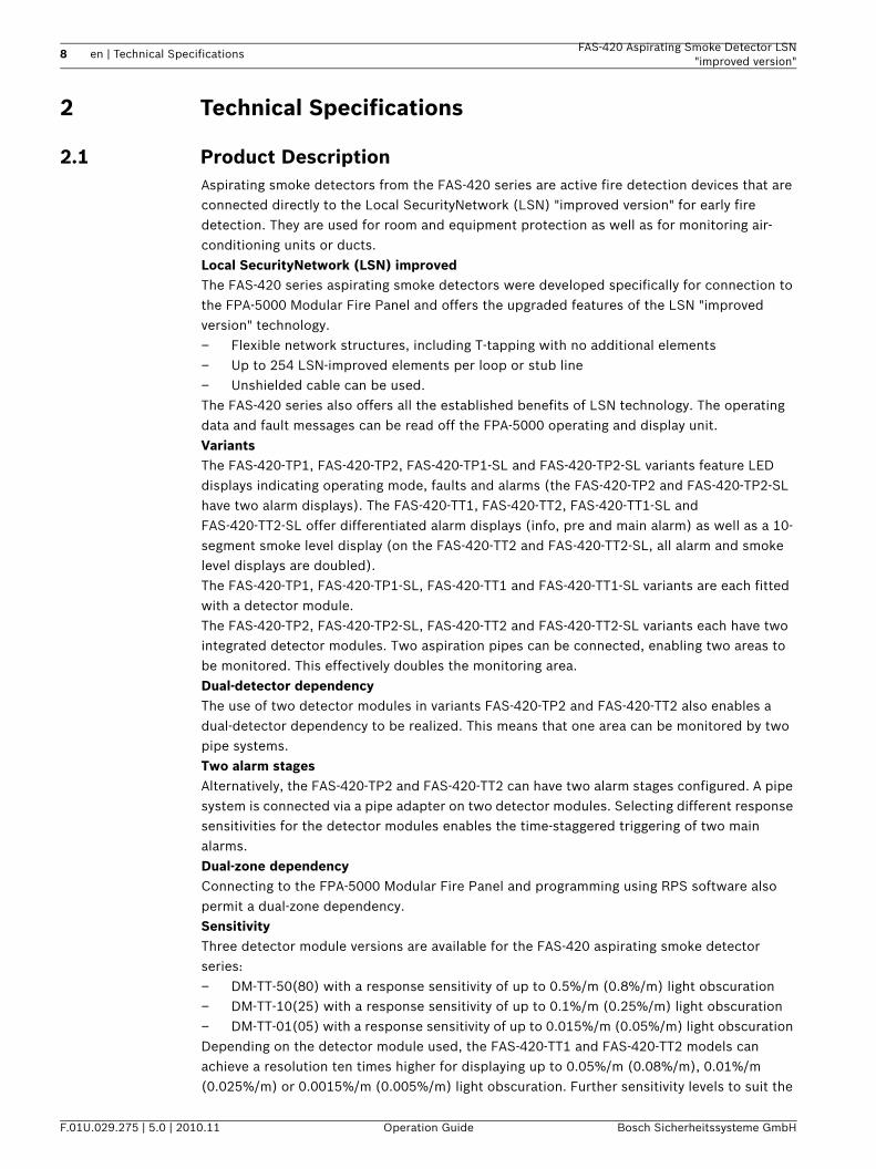
2.1 Product DescriptionAspirating smoke detectors from the FAS-420 series are active fire detection devices that are connected directly to the Local SecurityNetwork (LSN) "improved version" for early fire detection. They are used for room and equipment protection as well as for monitoring air-conditioning units or ducts.Local SecurityNetwork (LSN) improvedThe FAS-420 series aspirating smoke detectors were developed specifically for connection to the FPA-5000 Modular Fire Panel and offers the upgraded features of the LSN "improved version" technology.– Flexible network structures, including T-tapping with no additional elements – Up to 254 LSN-improved elements per loop or stub line – Unshielded cable can be used. The FAS-420 series also offers all the established benefits of LSN technology. The operating data and fault messages can be read off the FPA-5000 operating and display unit.VariantsThe FAS-420-TP1, FAS-420-TP2, FAS-420-TP1-SL and FAS-420-TP2-SL variants feature LED displays indicating operating mode, faults and alarms (the FAS-420-TP2 and FAS-420-TP2-SL have two alarm displays). The FAS-420-TT1, FAS-420-TT2, FAS-420-TT1-SL and FAS-420-TT2-SL offer differentiated alarm displays (info, pre and main alarm) as well as a 10-segment smoke level display (on the FAS-420-TT2 and FAS-420-TT2-SL, all alarm and smoke level displays are doubled).The FAS-420-TP1, FAS-420-TP1-SL, FAS-420-TT1 and FAS-420-TT1-SL variants are each fitted with a detector module. The FAS-420-TP2, FAS-420-TP2-SL, FAS-420-TT2 and FAS-420-TT2-SL variants each have two integrated detector modules. Two aspiration pipes can be connected, enabling two areas to be monitored. This effectively doubles the monitoring area.Dual-detector dependencyThe use of two detector modules in variants FAS-420-TP2 and FAS-420-TT2 also enables a dual-detector dependency to be realized. This means that one area can be monitored by two pipe systems.Two alarm stagesAlternatively, the FAS-420-TP2 and FAS-420-TT2 can have two alarm stages configured. A pipe system is connected via a pipe adapter on two detector modules. Selecting different response sensitivities for the detector modules enables the time-staggered triggering of two main alarms.Dual-zone dependencyConnecting to the FPA-5000 Modular Fire Panel and programming using RPS software also permit a dual-zone dependency.SensitivityThree detector module versions are available for the FAS-420 aspirating smoke detector series:– DM-TT-50(80) with a response sensitivity of up to 0.5%/m (0.8%/m) light obscuration– DM-TT-10(25) with a response sensitivity of up to 0.1%/m (0.25%/m) light obscuration– DM-TT-01(05) with a response sensitivity of up to 0.015%/m (0.05%/m) light obscuration Depending on the detector module used, the FAS-420-TT1 and FAS-420-TT2 models can achieve a resolution ten times higher for displaying up to 0.05%/m (0.08%/m), 0.01%/m (0.025%/m) or 0.0015%/m (0.005%/m) light obscuration. Further sensitivity levels to suit the
FAS-420 Aspirating Smoke Detector LSN "improved version"
Technical Specifications | en 9
Bosch Sicherheitssysteme GmbH Operation Guide F.01U.029.275 | 5.0 | 2010.11
application range can be selected via the RPS programming software.
The new High-Power-Light-Source technology permits a broad detection spectrum over all standardized fires (for response sensitivity, detection points, see Section 3.4 Defining the Response Sensitivity, page 37).LOGIC · SENSThe intelligent signal processing LOGIC · SENS distinguishes between deception variables and fire events in order to prevent false alarms.Reliable airflow monitoringAnalogous to point-type smoke detectors, which are monitored electronically for wire breaks and short-circuits, highly sensitive and dependable airflow monitoring is required for smoke aspiration systems. The airflow sensors used in the FAS-420 series reliably detect malfunctions such as pipe breakage or obstructions in the air sampling openings.The small airflow unit also contains a dynamic airflow sensor that enables a response to small and fast changes in the airflow.Airflow monitoring is temperature-compensated and can be set depending on the air pressure.Patented air sampling openingsThe air sampling openings of the pipe system require clearly defined bore diameters that depend on the planning and design. These precise air sampling openings are created using patented aspiration reducing film sheets, marking tape, and clips, which not only permit easy installation, but also prevent "whistling" noises. Another advantage is the quick and easy detection and checking of the air sampling opening diameters.Point-type detector projectionThe system’s aspiration points can be equated with point-type smoke detectors. The monitoring areas can therefore be planned in accordance with the applicable national regulations.DiagnosticsA system with FAS-ASD-DIAG Diagnostic Software, which enables quick and convenient error containment, is available for maintenance and service. The current and stored unit status is read-out via cable data transmission to the PC.Selecting the fan voltageThe fan voltage for special planning can be increased from 6.9 V to 9 V by relocating the fan jumper. This increases the air transport speed and therefore reduces detection time. For -SL variants, the fan voltage can also be set to 6.5 V.
NOTICE! The sensitivity value is based on measurements with standard test fires (old value in brackets).
10 en | Technical Specifications FAS-420 Aspirating Smoke Detector LSN"improved version"
F.01U.029.275 | 5.0 | 2010.11 Operation Guide Bosch Sicherheitssysteme GmbH
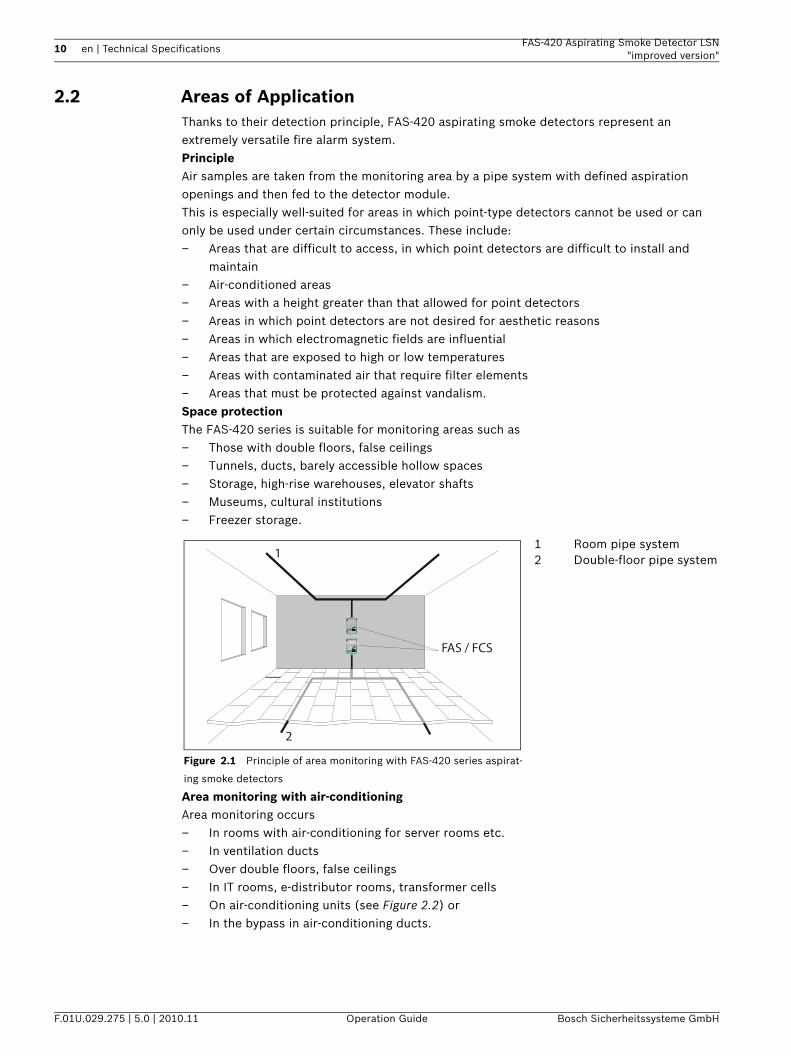
2.2 Areas of ApplicationThanks to their detection principle, FAS-420 aspirating smoke detectors represent an extremely versatile fire alarm system. PrincipleAir samples are taken from the monitoring area by a pipe system with defined aspiration openings and then fed to the detector module. This is especially well-suited for areas in which point-type detectors cannot be used or can only be used under certain circumstances. These include:– Areas that are difficult to access, in which point detectors are difficult to install and
maintain– Air-conditioned areas– Areas with a height greater than that allowed for point detectors– Areas in which point detectors are not desired for aesthetic reasons– Areas in which electromagnetic fields are influential– Areas that are exposed to high or low temperatures– Areas with contaminated air that require filter elements– Areas that must be protected against vandalism.Space protectionThe FAS-420 series is suitable for monitoring areas such as– Those with double floors, false ceilings– Tunnels, ducts, barely accessible hollow spaces– Storage, high-rise warehouses, elevator shafts– Museums, cultural institutions– Freezer storage.
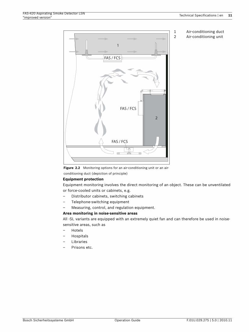
Area monitoring with air-conditioningArea monitoring occurs– In rooms with air-conditioning for server rooms etc.– In ventilation ducts– Over double floors, false ceilings– In IT rooms, e-distributor rooms, transformer cells– On air-conditioning units (see Figure 2.2) or– In the bypass in air-conditioning ducts.
Figure 2.1 Principle of area monitoring with FAS-420 series aspirat-
ing smoke detectors
1 Room pipe system2 Double-floor pipe system
FAS / FCS
1
2
T IT AN U S M IC R O ·S EN S ®
E
D
C
B
A
10987654321
T IT AN U S M IC R O ·S EN S ®
E
D
C
B
A
10987654321
FAS-420 Aspirating Smoke Detector LSN "improved version"
Technical Specifications | en 11
Bosch Sicherheitssysteme GmbH Operation Guide F.01U.029.275 | 5.0 | 2010.11
Equipment protectionEquipment monitoring involves the direct monitoring of an object. These can be unventilated or force-cooled units or cabinets, e.g.– Distributor cabinets, switching cabinets– Telephone-switching equipment– Measuring, control, and regulation equipment.Area monitoring in noise-sensitive areasAll -SL variants are equipped with an extremely quiet fan and can therefore be used in noise-sensitive areas, such as– Hotels– Hospitals– Libraries– Prisons etc.
Figure 2.2 Monitoring options for an air-conditioning unit or an air-
conditioning duct (depiction of principle)
1 Air-conditioning duct2 Air-conditioning unit
FAS / FCS
FAS / FCS
FAS / FCS
1
2
12 en | Technical Specifications FAS-420 Aspirating Smoke Detector LSN"improved version"
F.01U.029.275 | 5.0 | 2010.11 Operation Guide Bosch Sicherheitssysteme GmbH
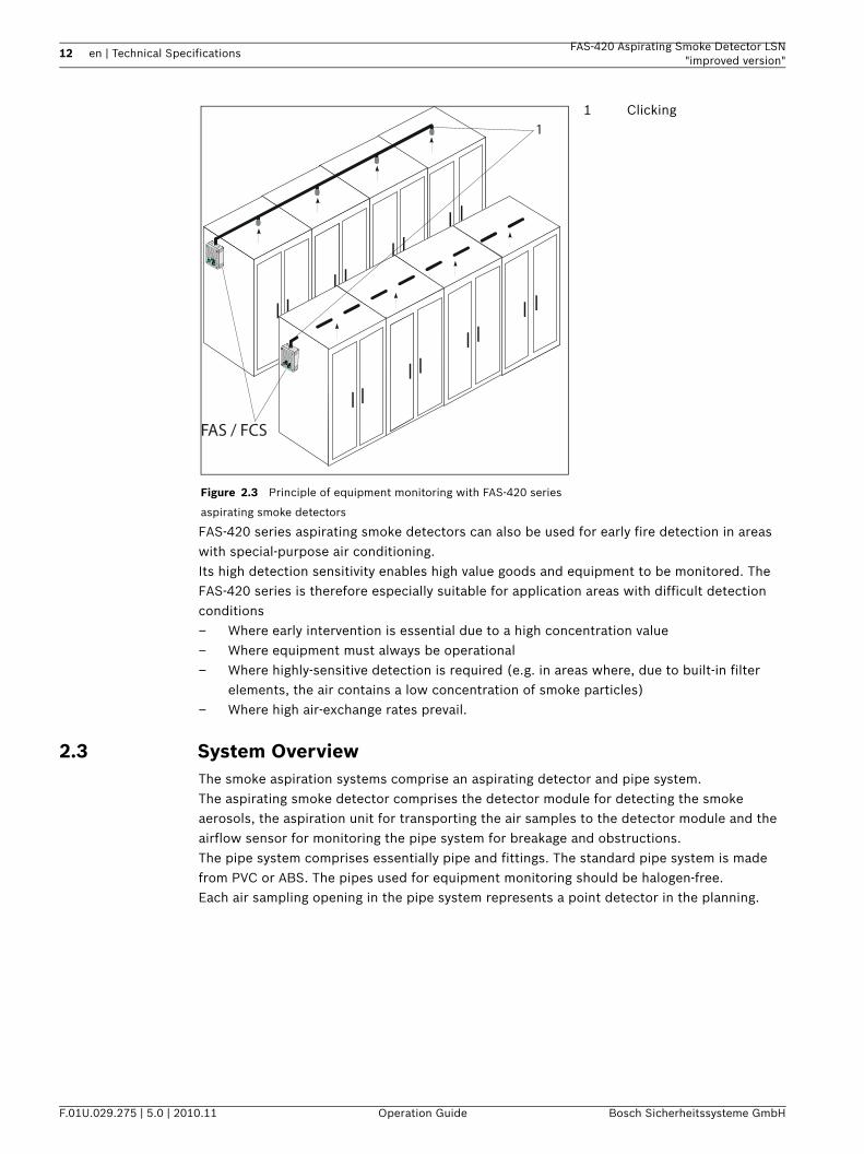
FAS-420 series aspirating smoke detectors can also be used for early fire detection in areas with special-purpose air conditioning.Its high detection sensitivity enables high value goods and equipment to be monitored. The FAS-420 series is therefore especially suitable for application areas with difficult detection conditions– Where early intervention is essential due to a high concentration value– Where equipment must always be operational– Where highly-sensitive detection is required (e.g. in areas where, due to built-in filter
elements, the air contains a low concentration of smoke particles)– Where high air-exchange rates prevail.
2.3 System OverviewThe smoke aspiration systems comprise an aspirating detector and pipe system.The aspirating smoke detector comprises the detector module for detecting the smoke aerosols, the aspiration unit for transporting the air samples to the detector module and the airflow sensor for monitoring the pipe system for breakage and obstructions.The pipe system comprises essentially pipe and fittings. The standard pipe system is made from PVC or ABS. The pipes used for equipment monitoring should be halogen-free.Each air sampling opening in the pipe system represents a point detector in the planning.
Figure 2.3 Principle of equipment monitoring with FAS-420 series
aspirating smoke detectors
1 Clicking1
FAS / FCS
FAS-420 Aspirating Smoke Detector LSN "improved version"
Technical Specifications | en 13
Bosch Sicherheitssysteme GmbH Operation Guide F.01U.029.275 | 5.0 | 2010.11
To guarantee reliable operation even under the most difficult conditions (clean rooms, recycling area), there are numerous accessories available, such as air filters, water separators and detonation safety barriers.
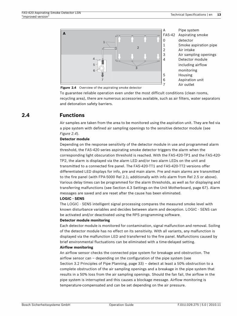
2.4 FunctionsAir samples are taken from the area to be monitored using the aspiration unit. They are fed via a pipe system with defined air sampling openings to the sensitive detector module (see Figure 2.4).Detector moduleDepending on the response sensitivity of the detector module in use and programmed alarm threshold, the FAS-420 series aspirating smoke detector triggers the alarm when the corresponding light obscuration threshold is reached. With the FAS-420-TP1 and the FAS-420-TP2, the alarm is displayed via the alarm LED and/or two alarm LEDs on the unit and transmitted to a connected fire panel. The FAS-420-TT1 and FAS-420-TT2 versions offer differentiated LED displays for info, pre and main alarm. Pre and main alarms are transmitted to the fire panel (with FPA-5000 Rel 2.1; additionally with info alarm from Rel 2.5 or above).Various delay times can be programmed for the alarm thresholds, as well as for displaying and transferring malfunctions (see Section 4.3 Settings on the Unit Motherboard, page 67). Alarm messages are saved and are reset after the cause has been eliminated.LOGIC · SENSThe LOGIC · SENS intelligent signal processing compares the measured smoke level with known disturbance variables and decides between alarm and deception. LOGIC · SENS can be activated and/or deactivated using the RPS programming software.Detector module monitoringEach detector module is monitored for contamination, signal malfunction and removal. Soiling of the detector module has no effect on its sensitivity. With all variants, any malfunction is displayed via the malfunction LED and transferred to the fire panel. Malfunctions caused by brief environmental fluctuations can be eliminated with a time-delayed setting.Airflow monitoringAn airflow sensor checks the connected pipe system for breakage and obstruction. The airflow sensor can – depending on the configuration of the pipe system (see Section 3.2 Principles of Pipe Planning, page 33) – detect at least a 50% obstruction to a complete obstruction of the air sampling openings and a breakage in the pipe system that results in a 50% loss from the air sampling openings. Should the fan fail, the airflow in the pipe system is interrupted and this causes a blockage message. Airflow monitoring is temperature-compensated and can be set depending on the air pressure.
Figure 2.4 Overview of the aspirating smoke detector
A Pipe systemFAS-420
Aspirating smoke detector
1 Smoke aspiration pipe2 Air intake3 Air sampling openings4 Detector module
including airflow monitoring
5 Housing6 Aspiration unit7 Air outlet
2
7
6
53
1
A
4
14 en | Technical Specifications FAS-420 Aspirating Smoke Detector LSN"improved version"
F.01U.029.275 | 5.0 | 2010.11 Operation Guide Bosch Sicherheitssysteme GmbH
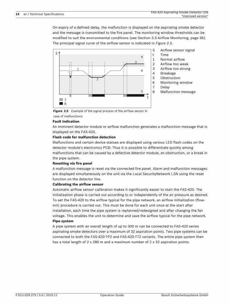
On expiry of a defined delay, the malfunction is displayed on the aspirating smoke detector and the message is transmitted to the fire panel. The monitoring window thresholds can be modified to suit the environmental conditions (see Section 3.3 Airflow Monitoring, page 36).The principal signal curve of the airflow sensor is indicated in Figure 2.5.
Fault IndicationAn imminent detector module or airflow malfunction generates a malfunction message that is displayed on the FAS-420. Flash code for malfunction detectionMalfunctions and certain device statues are displayed using various LED flash codes on the detector module's electronics PCB. Thus it is possible to differentiate quickly among malfunctions that can be caused by a defective detector module, an obstruction, or a break in the pipe system.Resetting via fire panelA malfunction message is reset via the connected fire panel. Alarm and malfunction messages are displayed simultaneously on the unit via the Local SecurityNetwork LSN using the reset function on the detector line.Calibrating the airflow sensorAutomatic airflow sensor calibration makes it significantly easier to start the FAS-420. The initialization phase is carried out according to or independently of the air pressure as desired.To set the FAS-420 to the airflow typical for the pipe network, an airflow initialization (flow-init) procedure is carried out. This must be done for each unit once at the start after installation, each time the pipe system is replanned/redesigned and after changing the fan voltage. This enables the unit to determine and save the airflow typical for the pipe network.Pipe systemA pipe system with an overall length of up to 300 m can be connected to FAS-420 series aspirating smoke detectors over a maximum of 32 aspiration points. Two pipe systems can be connected to both the FAS-420-TP2 and FAS-420-TT2 variants. The entire pipe system then has a total length of 2 x 280 m and a maximum number of 2 x 32 aspiration points.
Figure 2.5 Example of the signal process of the airflow sensor in
case of malfunctions
S Airflow sensor signalt Time1 Normal airflow2 Airflow too weak3 Airflow too strong 4 Breakage5 Obstruction6 Monitoring window7 Delay8 Malfunction message
S
t
4
78
61
2
5
3
FAS-420 Aspirating Smoke Detector LSN "improved version"
Technical Specifications | en 15
Bosch Sicherheitssysteme GmbH Operation Guide F.01U.029.275 | 5.0 | 2010.11
2.5 FAS-420 Series Aspirating Smoke Detectors and Accessories
2.5.1 Overview
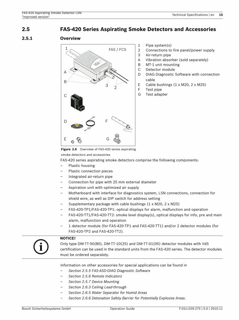
FAS-420 series aspirating smoke detectors comprise the following components:– Plastic housing– Plastic connection pieces– Integrated air-return pipe– Connection for pipe with 25 mm external diameter– Aspiration unit with optimized air supply– Motherboard with interface for diagnostics system, LSN connections, connection for
shield wire, as well as DIP switch for address setting– Supplementary package with cable bushings (1 x M20, 2 x M25)– FAS-420-TP1/FAS-420-TP1: optical displays for alarm, malfunction and operation– FAS-420-TT1/FAS-420-TT2: smoke level display(s), optical displays for info, pre and main
alarm, malfunction and operation– 1 detector module (for FAS-420-TP1 and FAS-420-TT1) and/or 2 detector modules (for
FAS-420-TP2 and FAS-420-TT2).
Information on other accessories for special applications can be found in– Section 2.5.5 FAS-ASD-DIAG Diagnostic Software– Section 2.5.6 Remote Indicators– Section 2.5.7 Device Mounting– Section 2.6.3 Ceiling Lead-through– Section 2.6.5 Water Separator for Humid Areas– Section 2.6.6 Detonation Safety Barrier for Potentially Explosive Areas.
Figure 2.6 Overview of FAS-420 series aspirating
smoke detectors and accessories
1 Pipe system(s)2 Connections to fire panel/power supply3 Air-return pipeA Vibration absorber (sold separately)B MT-1 unit mountingC Detector moduleD DIAG Diagnostic Software with connection
cableE Cable bushings (1 x M20, 2 x M25)F Test pipeG Test adapter
2
A
3
C
E G
F
1
B
D
FAS / FCS
NOTICE! Only type DM-TT-50(80), DM-TT-10(25) and DM-TT-01(05) detector modules with VdS certification can be used in the standard units from the FAS-420 series. The detector modules must be ordered separately.
16 en | Technical Specifications FAS-420 Aspirating Smoke Detector LSN"improved version"
F.01U.029.275 | 5.0 | 2010.11 Operation Guide Bosch Sicherheitssysteme GmbH
2.5.2 FAS-420 Connections
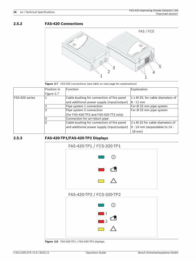
Figure 2.7 FAS-420 connections (see table on next page for explanations)
2.5.3 FAS-420-TP1/FAS-420-TP2 Displays
Figure 2.8 FAS-420-TP1 / FAS-420-TP2 displays
12
3
14
5
FAS-420 series
FAS-420 serie
s
FAS / FCS
Position in Figure 2.7
Function Explanation
FAS-420 series 1 Cable bushing for connection of fire panel and additional power supply (input/output)
1 x M 20, for cable diameters of 8 - 12 mm
2 Pipe system 1 connection For Ø 25 mm pipe system3 Pipe system 2 connection
(for FAS-420-TP2 and FAS-420-TT2 only) For Ø 25 mm pipe system
4 Connection for air-return pipe5 Cable bushing for connection of fire panel
and additional power supply (input/output)2 x M 25 for cable diameters of 9 - 14 mm (expandable to 14 -18 mm)
FAS-420-TP1 / FCS-320-TP1
FAS-420-TP2 / FCS-320-TP2
1
2
FAS-420 Aspirating Smoke Detector LSN "improved version"
Technical Specifications | en 17
Bosch Sicherheitssysteme GmbH Operation Guide F.01U.029.275 | 5.0 | 2010.11
2.5.4 FAS-420-TT1/FAS-420-TT2 Displays
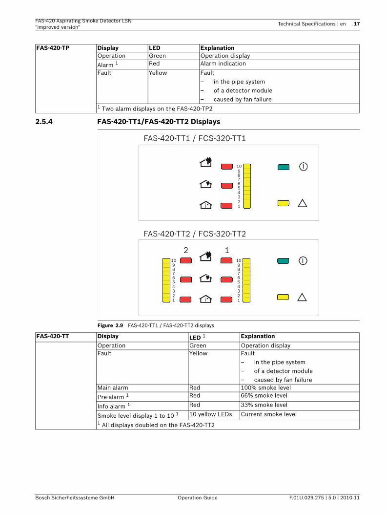
Figure 2.9 FAS-420-TT1 / FAS-420-TT2 displays
FAS-420-TP Display LED ExplanationOperation Green Operation display
Alarm 1 Red Alarm indication
Fault Yellow Fault– in the pipe system– of a detector module– caused by fan failure
1 Two alarm displays on the FAS-420-TP2
i 123456789
10
FAS-420-TT1 / FCS-320-TT1
FAS-420-TT2 / FCS-320-TT2
i 123456789
10
123456789
10
12
FAS-420-TT Display LED 1 Explanation
Operation Green Operation displayFault Yellow Fault
– in the pipe system– of a detector module– caused by fan failure
Main alarm Red 100% smoke level
Pre-alarm 1 Red 66% smoke level
Info alarm 1 Red 33% smoke level
Smoke level display 1 to 10 1 10 yellow LEDs Current smoke level1 All displays doubled on the FAS-420-TT2
18 en | Technical Specifications FAS-420 Aspirating Smoke Detector LSN"improved version"
F.01U.029.275 | 5.0 | 2010.11 Operation Guide Bosch Sicherheitssysteme GmbH
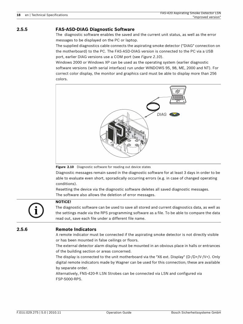
2.5.5 FAS-ASD-DIAG Diagnostic SoftwareThe diagnostic software enables the saved and the current unit status, as well as the error messages to be displayed on the PC or laptop. The supplied diagnostics cable connects the aspirating smoke detector ("DIAG" connection on the motherboard) to the PC. The FAS-ASD-DIAG version is connected to the PC via a USB port, earlier DIAG versions use a COM port (see Figure 2.10). Windows 2000 or Windows XP can be used as the operating system (earlier diagnostic software versions (with serial interface) run under WINDOWS 95, 98, ME, 2000 and NT). For correct color display, the monitor and graphics card must be able to display more than 256 colors.
Figure 2.10 Diagnostic software for reading out device states
Diagnostic messages remain saved in the diagnostic software for at least 3 days in order to be able to evaluate even short, sporadically occurring errors (e.g. in case of changed operating conditions).Resetting the device via the diagnostic software deletes all saved diagnostic messages.The software also allows the deletion of error messages.
2.5.6 Remote IndicatorsA remote indicator must be connected if the aspirating smoke detector is not directly visible or has been mounted in false ceilings or floors.The external detector alarm display must be mounted in an obvious place in halls or entrances of the building section or areas concerned.The display is connected to the unit motherboard via the "X6 ext. Display" (D-/D+/V-/V+). Only digital remote indicators made by Wagner can be used for this connection; these are available by separate order.Alternatively, FNS-420-R LSN Strobes can be connected via LSN and configured via FSP-5000-RPS.
DIAG
NOTICE! The diagnostic software can be used to save all stored and current diagnostics data, as well as the settings made via the RPS programming software as a file. To be able to compare the data read out, save each file under a different file name.
FAS-420 Aspirating Smoke Detector LSN "improved version"
Technical Specifications | en 19
Bosch Sicherheitssysteme GmbH Operation Guide F.01U.029.275 | 5.0 | 2010.11
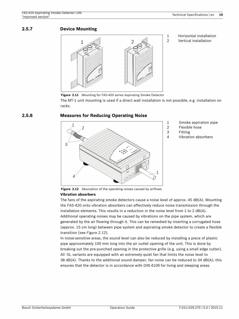
2.5.7 Device Mounting
The MT-1 unit mounting is used if a direct wall installation is not possible, e.g. installation on racks.
2.5.8 Measures for Reducing Operating Noise
Vibration absorbersThe fans of the aspirating smoke detectors cause a noise level of approx. 45 dB(A). Mounting the FAS-420 onto vibration absorbers can effectively reduce noise transmission through the installation elements. This results in a reduction in the noise level from 1 to 2 dB(A).Additional operating noises may be caused by vibrations on the pipe system, which are generated by the air flowing through it. This can be remedied by inserting a corrugated hose (approx. 15 cm long) between pipe system and aspirating smoke detector to create a flexible transition (see Figure 2.12).In noise-sensitive areas, the sound level can also be reduced by installing a piece of plastic pipe approximately 100 mm long into the air outlet opening of the unit. This is done by breaking out the pre-punched opening in the protective grille (e.g. using a small edge cutter).All -SL variants are equipped with an extremely quiet fan that limits the noise level to 38 dB(A). Thanks to the additional sound damper, fan noise can be reduced to 34 dB(A); this ensures that the detector is in accordance with DIN 4109 for living and sleeping areas.
Figure 2.11 Mounting for FAS-420 series Aspirating Smoke Detector
1 Horizontal installation2 Vertical installation1 2
FAS-420 series
FAS-420 series
Figure 2.12 Absorption of the operating noises caused by airflows
1 Smoke aspiration pipe2 Flexible hose3 Fitting4 Vibration absorbers
1
1
2
3
4
FAS-420 serie
s
20 en | Technical Specifications FAS-420 Aspirating Smoke Detector LSN"improved version"
F.01U.029.275 | 5.0 | 2010.11 Operation Guide Bosch Sicherheitssysteme GmbH
2.6 Pipe System Components
2.6.1 Overview
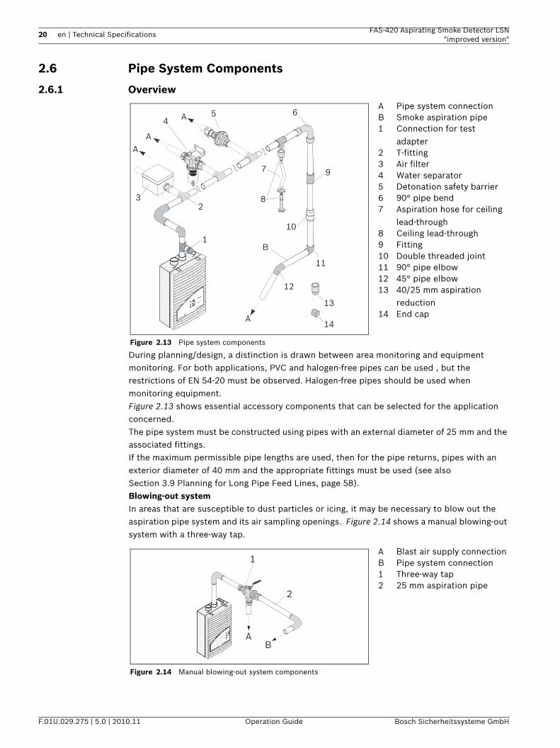
During planning/design, a distinction is drawn between area monitoring and equipment monitoring. For both applications, PVC and halogen-free pipes can be used , but the restrictions of EN 54-20 must be observed. Halogen-free pipes should be used when monitoring equipment.Figure 2.13 shows essential accessory components that can be selected for the application concerned.The pipe system must be constructed using pipes with an external diameter of 25 mm and the associated fittings.If the maximum permissible pipe lengths are used, then for the pipe returns, pipes with an exterior diameter of 40 mm and the appropriate fittings must be used (see also Section 3.9 Planning for Long Pipe Feed Lines, page 58).Blowing-out systemIn areas that are susceptible to dust particles or icing, it may be necessary to blow out the aspiration pipe system and its air sampling openings. Figure 2.14 shows a manual blowing-out system with a three-way tap.
Figure 2.13 Pipe system components
A Pipe system connectionB Smoke aspiration pipe1 Connection for test
adapter2 T-fitting3 Air filter4 Water separator5 Detonation safety barrier6 90° pipe bend7 Aspiration hose for ceiling
lead-through8 Ceiling lead-through9 Fitting10 Double threaded joint11 90° pipe elbow12 45° pipe elbow13 40/25 mm aspiration
reduction14 End cap
Figure 2.14 Manual blowing-out system components
A Blast air supply connectionB Pipe system connection1 Three-way tap2 25 mm aspiration pipe
A
A
A
45
32
7
6
8
9
10
11
12
13
1
14
A
B
FAS-420 series
A
1
2
BFAS-420 se
ries
FAS-420 Aspirating Smoke Detector LSN "improved version"
Technical Specifications | en 21
Bosch Sicherheitssysteme GmbH Operation Guide F.01U.029.275 | 5.0 | 2010.11
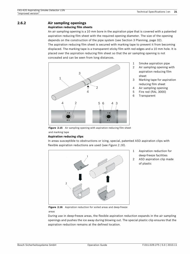
2.6.2 Air sampling openingsAspiration reducing film sheetsAn air sampling opening is a 10 mm bore in the aspiration pipe that is covered with a patented aspiration reducing film sheet with the required opening diameter. The size of the opening depends on the construction of the pipe system (see Section 3 Planning, page 32).The aspiration reducing film sheet is secured with marking tape to prevent it from becoming displaced. The marking tape is a transparent sticky film with red edges and a 10 mm hole. It is placed over the aspiration reducing film sheet so that the air sampling opening is not concealed and can be seen from long distances.
Aspiration reducing clipsIn areas susceptible to obstructions or icing, special, patented ASD aspiration clips with flexible aspiration reductions are used (see Figure 2.16).
During use in deep-freeze areas, the flexible aspiration reduction expands in the air sampling openings and pushes the ice away during blowing out. The special plastic clip ensures that the aspiration reduction remains at the defined location.
Figure 2.15 Air sampling opening with aspiration reducing film sheet
and marking tape
1 Smoke aspiration pipe2 Air sampling opening with
aspiration reducing film sheet
3 Marking tape for aspiration reducing film sheet
4 Air sampling opening5 Fire red (RAL 3000)6 Transparent
Figure 2.16 Aspiration reduction for soiled areas and deep-freeze
areas
1 Aspiration reduction for deep-freeze facilities
2 ASD aspiration clip made of plastic
1
3
36
2
4
4
452
1
2
22 en | Technical Specifications FAS-420 Aspirating Smoke Detector LSN"improved version"
F.01U.029.275 | 5.0 | 2010.11 Operation Guide Bosch Sicherheitssysteme GmbH
As the clips are more stable under pressure and the elastic rubber insert significantly improves the cleaning effect, they are used for all plans and designs which require a blow-off system due to environmental influences (e.g. increased exposure to dust). The standard AF-x aspiration reducing film sheets and the marking tapes are not suitable for use in low-temperature areas.The aspiration reductions with plastic clips are available separately.
2.6.3 Ceiling Lead-through
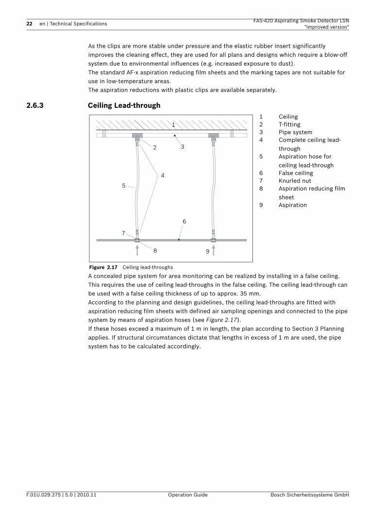
A concealed pipe system for area monitoring can be realized by installing in a false ceiling. This requires the use of ceiling lead-throughs in the false ceiling. The ceiling lead-through can be used with a false ceiling thickness of up to approx. 35 mm.According to the planning and design guidelines, the ceiling lead-throughs are fitted with aspiration reducing film sheets with defined air sampling openings and connected to the pipe system by means of aspiration hoses (see Figure 2.17).If these hoses exceed a maximum of 1 m in length, the plan according to Section 3 Planning applies. If structural circumstances dictate that lengths in excess of 1 m are used, the pipe system has to be calculated accordingly.
Figure 2.17 Ceiling lead-throughs
1 Ceiling2 T-fitting3 Pipe system4 Complete ceiling lead-
through5 Aspiration hose for
ceiling lead-through6 False ceiling7 Knurled nut8 Aspiration reducing film
sheet9 Aspiration
1
2 3
4
6
7
8 9
5
FAS-420 Aspirating Smoke Detector LSN "improved version"
Technical Specifications | en 23
Bosch Sicherheitssysteme GmbH Operation Guide F.01U.029.275 | 5.0 | 2010.11
2.6.4 Air-Return Pipe for Pressure Areas and Atmospheric Loads
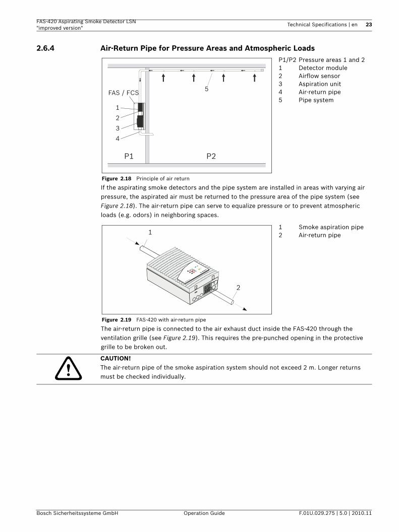
If the aspirating smoke detectors and the pipe system are installed in areas with varying air pressure, the aspirated air must be returned to the pressure area of the pipe system (see Figure 2.18). The air-return pipe can serve to equalize pressure or to prevent atmospheric loads (e.g. odors) in neighboring spaces.
The air-return pipe is connected to the air exhaust duct inside the FAS-420 through the ventilation grille (see Figure 2.19). This requires the pre-punched opening in the protective grille to be broken out.
Figure 2.18 Principle of air return
P1/P2 Pressure areas 1 and 21 Detector module2 Airflow sensor3 Aspiration unit4 Air-return pipe5 Pipe system
Figure 2.19 FAS-420 with air-return pipe
1 Smoke aspiration pipe2 Air-return pipe
P1 P2
5
1
FAS / FCS
2
3
4
1
2FAS-420 se
ries
CAUTION! The air-return pipe of the smoke aspiration system should not exceed 2 m. Longer returns must be checked individually.
24 en | Technical Specifications FAS-420 Aspirating Smoke Detector LSN"improved version"
F.01U.029.275 | 5.0 | 2010.11 Operation Guide Bosch Sicherheitssysteme GmbH
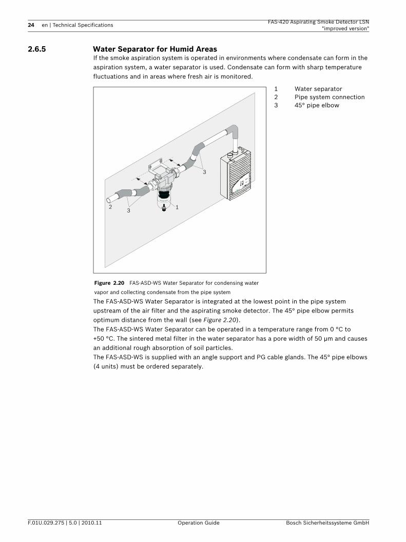
2.6.5 Water Separator for Humid AreasIf the smoke aspiration system is operated in environments where condensate can form in the aspiration system, a water separator is used. Condensate can form with sharp temperature fluctuations and in areas where fresh air is monitored.
The FAS-ASD-WS Water Separator is integrated at the lowest point in the pipe system upstream of the air filter and the aspirating smoke detector. The 45° pipe elbow permits optimum distance from the wall (see Figure 2.20).The FAS-ASD-WS Water Separator can be operated in a temperature range from 0 °C to +50 °C. The sintered metal filter in the water separator has a pore width of 50 µm and causes an additional rough absorption of soil particles.The FAS-ASD-WS is supplied with an angle support and PG cable glands. The 45° pipe elbows (4 units) must be ordered separately.
Figure 2.20 FAS-ASD-WS Water Separator for condensing water
vapor and collecting condensate from the pipe system
1 Water separator2 Pipe system connection3 45° pipe elbow
123
3
FAS-420 series
FAS-420 Aspirating Smoke Detector LSN "improved version"
Technical Specifications | en 25
Bosch Sicherheitssysteme GmbH Operation Guide F.01U.029.275 | 5.0 | 2010.11
2.6.6 Detonation Safety Barrier for Potentially Explosive Areas
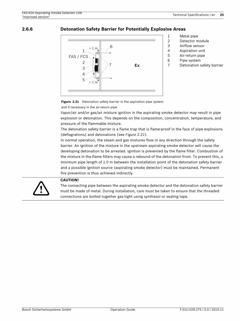
Vapor/air and/or gas/air mixture ignition in the aspirating smoke detector may result in pipe explosion or detonation. This depends on the composition, concentration, temperature, and pressure of the flammable mixture.The detonation safety barrier is a flame trap that is flame-proof in the face of pipe explosions (deflagrations) and detonations (see Figure 2.21).In normal operation, the steam and gas mixtures flow in any direction through the safety barrier. An ignition of the mixture in the upstream aspirating smoke detector will cause the developing detonation to be arrested. Ignition is prevented by the flame filter. Combustion of the mixture in the flame filters may cause a rebound of the detonation front. To prevent this, a minimum pipe length of 1.0 m between the installation point of the detonation safety barrier and a possible ignition source (aspirating smoke detector) must be maintained. Permanent fire prevention is thus achieved indirectly.
Figure 2.21 Detonation safety barrier in the aspiration pipe system
and if necessary in the air-return pipe
1 Metal pipe2 Detector module 3 Airflow sensor4 Aspiration unit5 Air-return pipe6 Pipe system7 Detonation safety barrierEx
FAS / FCS1
6
72345
> 1 m
> 1 m
CAUTION! The connecting pipe between the aspirating smoke detector and the detonation safety barrier must be made of metal. During installation, care must be taken to ensure that the threaded connections are bolted together gas-tight using synthesol or sealing tape.
26 en | Technical Specifications FAS-420 Aspirating Smoke Detector LSN"improved version"
F.01U.029.275 | 5.0 | 2010.11 Operation Guide Bosch Sicherheitssysteme GmbH
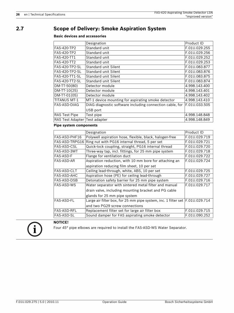
2.7 Scope of Delivery: Smoke Aspiration SystemBasic devices and accessories
Pipe system components
Designation Product IDFAS-420-TP2 Standard unit F.01U.029.255FAS-420-TP2 Standard unit F.01U.029.256FAS-420-TT1 Standard unit F.01U.029.252FAS-420-TT2 Standard unit F.01U.029.253FAS-420-TP2-SL Standard unit Silent F.01U.083.877FAS-420-TP2-SL Standard unit Silent F.01U.083.876FAS-420-TT1-SL Standard unit Silent F.01U.083.875FAS-420-TT2-SL Standard unit Silent F.01U.083.874DM-TT-50(80) Detector module 4.998.143.400DM-TT-10(25) Detector module 4.998.143.401DM-TT-01(05) Detector module 4.998.143.402TITANUS MT-1 MT-1 device mounting for aspirating smoke detector 4.998.143.410FAS-ASD-DIAG DIAG diagnostic software including connection cable, for
USB portF.01U.033.505
RAS Test Pipe Test pipe 4.998.148.848RAS Test Adapter Test adapter 4.998.148.849
Designation Product IDFAS-ASD-PHF16 Polywell aspiration hose, flexible, black, halogen-free F.01U.029.719FAS-ASD-TRPG16 Ring nut with PG16 internal thread, 5 per set F.01U.029.721FAS-ASD-CSL Quick-lock coupling, straight, PG16 internal thread F.01U.029.720FAS-ASD-3WT Three-way tap, incl. fittings, for 25 mm pipe system F.01U.029.718FAS-ASD-F Flange for ventilation duct F.01U.029.722FAS-ASD-AR Aspiration reduction, with 10 mm bore for attaching an
aspiration reducing film sheet, 10 per setF.01U.029.724
FAS-ASD-CLT Ceiling lead-through, white, ABS, 10 per set F.01U.029.725FAS-ASD-AHC Aspiration hose (PE) for ceiling lead-through F.01U.029.727FAS-ASD-DSB Detonation safety barrier for 25 mm pipe system F.01U.029.716FAS-ASD-WS Water separator with sintered metal filter and manual
drain valve, including mounting bracket and PG cable glands for 25 mm pipe system
F.01U.029.717
FAS-ASD-FL Large air filter box, for 25 mm pipe system, inc. 1 filter set and two PG29 screw connections
F.01U.029.714
FAS-ASD-RFL Replacement filter set for large air filter box F.01U.029.715FAS-ASD-SL Sound damper for FAS aspirating smoke detector F.01U.090.252
NOTICE! Four 45° pipe elbows are required to install the FAS-ASD-WS Water Separator.
FAS-420 Aspirating Smoke Detector LSN "improved version"
Technical Specifications | en 27
Bosch Sicherheitssysteme GmbH Operation Guide F.01U.029.275 | 5.0 | 2010.11
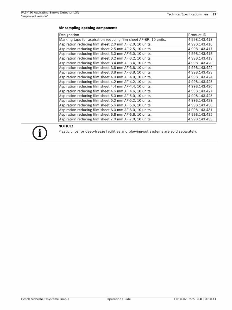
Air sampling opening components
Designation Product IDMarking tape for aspiration reducing film sheet AF-BR, 10 units. 4.998.143.413Aspiration reducing film sheet 2.0 mm AF-2.0, 10 units. 4.998.143.416Aspiration reducing film sheet 2.5 mm AF-2.5, 10 units. 4.998.143.417Aspiration reducing film sheet 3.0 mm AF-3.0, 10 units. 4.998.143.418Aspiration reducing film sheet 3.2 mm AF-3.2, 10 units. 4.998.143.419Aspiration reducing film sheet 3.4 mm AF-3.4, 10 units. 4.998.143.420Aspiration reducing film sheet 3.6 mm AF-3.6, 10 units. 4.998.143.422Aspiration reducing film sheet 3.8 mm AF-3.8, 10 units. 4.998.143.423Aspiration reducing film sheet 4.0 mm AF-4.0, 10 units. 4.998.143.424Aspiration reducing film sheet 4.2 mm AF-4.2, 10 units. 4.998.143.425Aspiration reducing film sheet 4.4 mm AF-4.4, 10 units. 4.998.143.426Aspiration reducing film sheet 4.6 mm AF-4.6, 10 units. 4.998.143.427Aspiration reducing film sheet 5.0 mm AF-5.0, 10 units. 4.998.143.428Aspiration reducing film sheet 5.2 mm AF-5.2, 10 units. 4.998.143.429Aspiration reducing film sheet 5.6 mm AF-5.6, 10 units. 4.998.143.430Aspiration reducing film sheet 6.0 mm AF-6.0, 10 units. 4.998.143.431Aspiration reducing film sheet 6.8 mm AF-6.8, 10 units. 4.998.143.432Aspiration reducing film sheet 7.0 mm AF-7.0, 10 units. 4.998.143.433
NOTICE! Plastic clips for deep-freeze facilities and blowing-out systems are sold separately.
28 en | Technical Specifications FAS-420 Aspirating Smoke Detector LSN"improved version"
F.01U.029.275 | 5.0 | 2010.11 Operation Guide Bosch Sicherheitssysteme GmbH
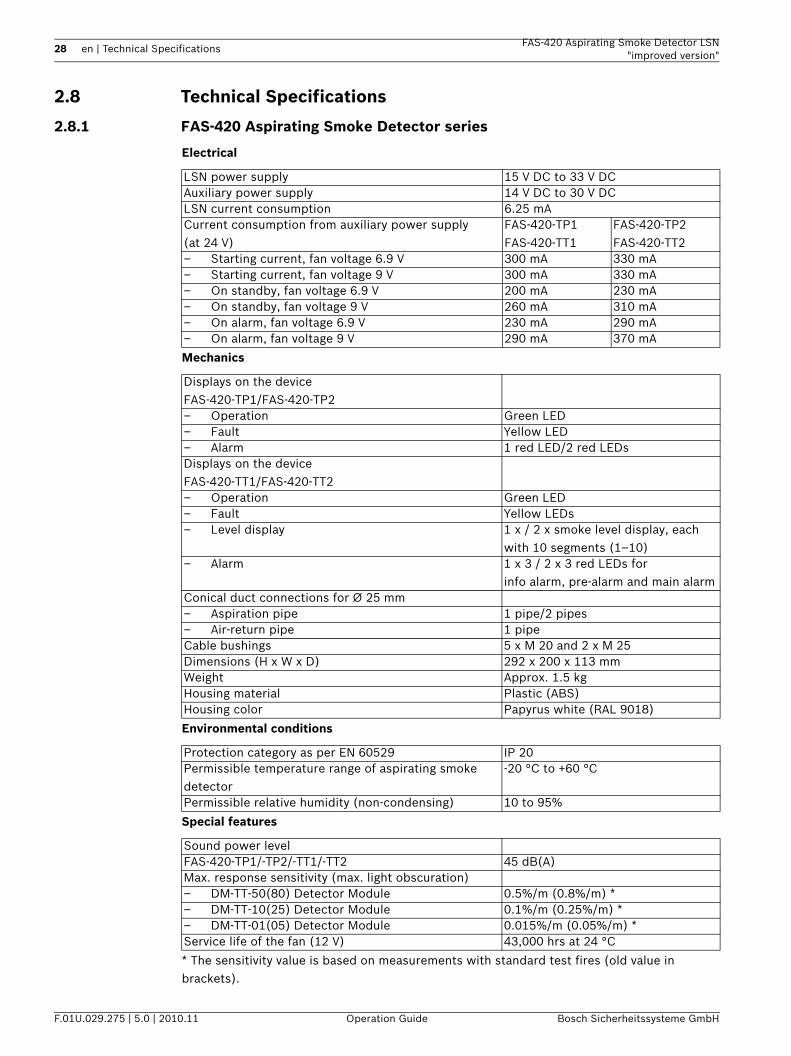
2.8 Technical Specifications
2.8.1 FAS-420 Aspirating Smoke Detector series
Electrical
Mechanics
Environmental conditions
Special features
* The sensitivity value is based on measurements with standard test fires (old value in brackets).
LSN power supply 15 V DC to 33 V DCAuxiliary power supply 14 V DC to 30 V DCLSN current consumption 6.25 mACurrent consumption from auxiliary power supply (at 24 V)
FAS-420-TP1FAS-420-TT1
FAS-420-TP2FAS-420-TT2
– Starting current, fan voltage 6.9 V 300 mA 330 mA– Starting current, fan voltage 9 V 300 mA 330 mA– On standby, fan voltage 6.9 V 200 mA 230 mA– On standby, fan voltage 9 V 260 mA 310 mA– On alarm, fan voltage 6.9 V 230 mA 290 mA– On alarm, fan voltage 9 V 290 mA 370 mA
Displays on the deviceFAS-420-TP1/FAS-420-TP2– Operation Green LED– Fault Yellow LED– Alarm 1 red LED/2 red LEDsDisplays on the deviceFAS-420-TT1/FAS-420-TT2– Operation Green LED– Fault Yellow LEDs– Level display 1 x / 2 x smoke level display, each
with 10 segments (1–10)– Alarm 1 x 3 / 2 x 3 red LEDs for
info alarm, pre-alarm and main alarmConical duct connections for Ø 25 mm– Aspiration pipe 1 pipe/2 pipes– Air-return pipe 1 pipeCable bushings 5 x M 20 and 2 x M 25Dimensions (H x W x D) 292 x 200 x 113 mmWeight Approx. 1.5 kgHousing material Plastic (ABS)Housing color Papyrus white (RAL 9018)
Protection category as per EN 60529 IP 20Permissible temperature range of aspirating smoke detector
-20 °C to +60 °C
Permissible relative humidity (non-condensing) 10 to 95%
Sound power levelFAS-420-TP1/-TP2/-TT1/-TT2 45 dB(A)Max. response sensitivity (max. light obscuration)– DM-TT-50(80) Detector Module 0.5%/m (0.8%/m) *– DM-TT-10(25) Detector Module 0.1%/m (0.25%/m) *– DM-TT-01(05) Detector Module 0.015%/m (0.05%/m) *Service life of the fan (12 V) 43,000 hrs at 24 °C
FAS-420 Aspirating Smoke Detector LSN "improved version"
Technical Specifications | en 29
Bosch Sicherheitssysteme GmbH Operation Guide F.01U.029.275 | 5.0 | 2010.11
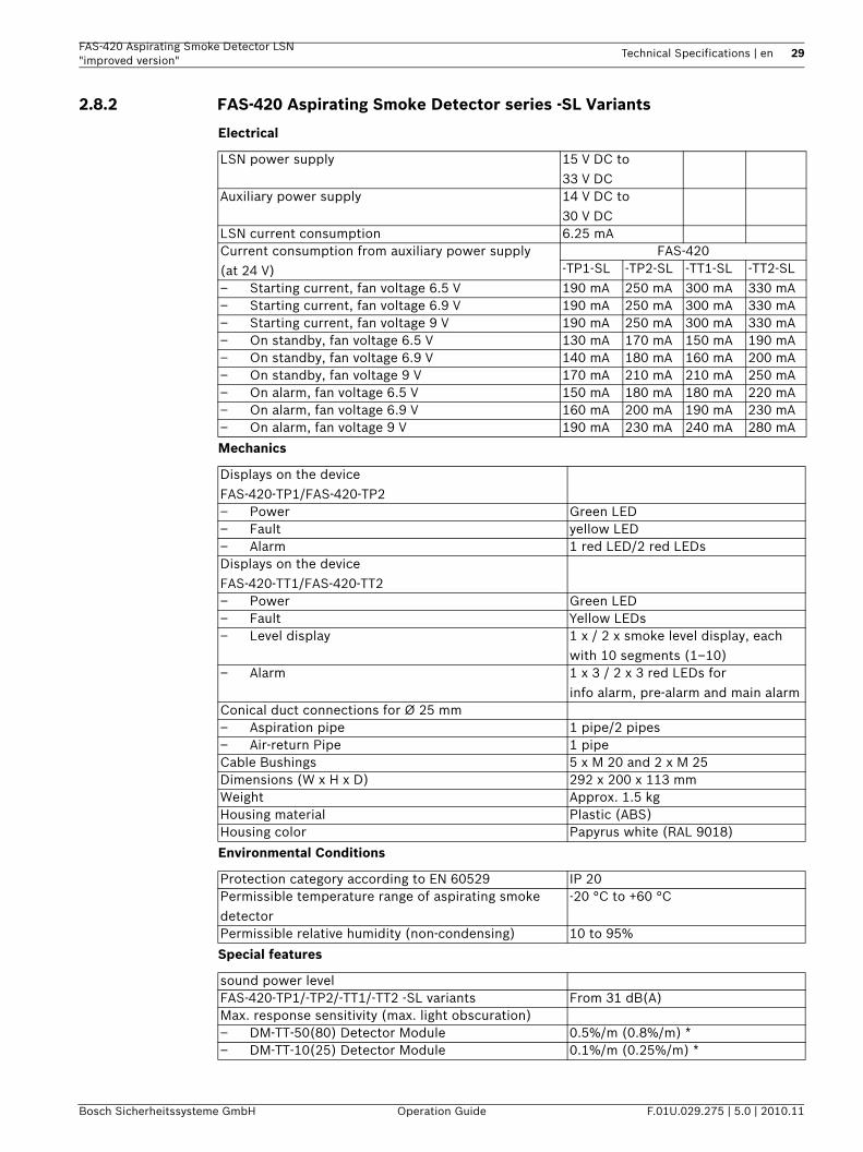
2.8.2 FAS-420 Aspirating Smoke Detector series -SL Variants
Electrical
Mechanics
Environmental Conditions
Special features
LSN power supply 15 V DC to 33 V DC
Auxiliary power supply 14 V DC to 30 V DC
LSN current consumption 6.25 mACurrent consumption from auxiliary power supply (at 24 V)
FAS-420-TP1-SL -TP2-SL -TT1-SL -TT2-SL
– Starting current, fan voltage 6.5 V 190 mA 250 mA 300 mA 330 mA– Starting current, fan voltage 6.9 V 190 mA 250 mA 300 mA 330 mA– Starting current, fan voltage 9 V 190 mA 250 mA 300 mA 330 mA– On standby, fan voltage 6.5 V 130 mA 170 mA 150 mA 190 mA– On standby, fan voltage 6.9 V 140 mA 180 mA 160 mA 200 mA– On standby, fan voltage 9 V 170 mA 210 mA 210 mA 250 mA– On alarm, fan voltage 6.5 V 150 mA 180 mA 180 mA 220 mA– On alarm, fan voltage 6.9 V 160 mA 200 mA 190 mA 230 mA– On alarm, fan voltage 9 V 190 mA 230 mA 240 mA 280 mA
Displays on the deviceFAS-420-TP1/FAS-420-TP2– Power Green LED– Fault yellow LED– Alarm 1 red LED/2 red LEDsDisplays on the deviceFAS-420-TT1/FAS-420-TT2– Power Green LED– Fault Yellow LEDs– Level display 1 x / 2 x smoke level display, each
with 10 segments (1–10)– Alarm 1 x 3 / 2 x 3 red LEDs for
info alarm, pre-alarm and main alarmConical duct connections for Ø 25 mm– Aspiration pipe 1 pipe/2 pipes– Air-return Pipe 1 pipeCable Bushings 5 x M 20 and 2 x M 25Dimensions (W x H x D) 292 x 200 x 113 mmWeight Approx. 1.5 kgHousing material Plastic (ABS)Housing color Papyrus white (RAL 9018)
Protection category according to EN 60529 IP 20Permissible temperature range of aspirating smoke detector
-20 °C to +60 °C
Permissible relative humidity (non-condensing) 10 to 95%
sound power levelFAS-420-TP1/-TP2/-TT1/-TT2 -SL variants From 31 dB(A)Max. response sensitivity (max. light obscuration)– DM-TT-50(80) Detector Module 0.5%/m (0.8%/m) *– DM-TT-10(25) Detector Module 0.1%/m (0.25%/m) *
30 en | Technical Specifications FAS-420 Aspirating Smoke Detector LSN"improved version"
F.01U.029.275 | 5.0 | 2010.11 Operation Guide Bosch Sicherheitssysteme GmbH
* The sensitivity value is based on measurements with standard test fires (old value in brackets).
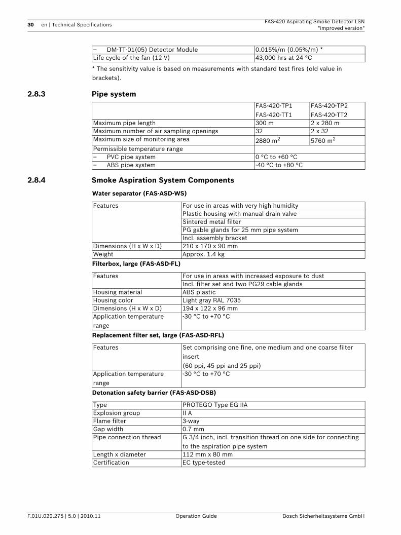
2.8.3 Pipe system
2.8.4 Smoke Aspiration System Components
Water separator (FAS-ASD-WS)
Filterbox, large (FAS-ASD-FL)
Replacement filter set, large (FAS-ASD-RFL)
Detonation safety barrier (FAS-ASD-DSB)
– DM-TT-01(05) Detector Module 0.015%/m (0.05%/m) *Life cycle of the fan (12 V) 43,000 hrs at 24 °C
FAS-420-TP1FAS-420-TT1
FAS-420-TP2FAS-420-TT2
Maximum pipe length 300 m 2 x 280 mMaximum number of air sampling openings 32 2 x 32Maximum size of monitoring area 2880 m2 5760 m2
Permissible temperature range– PVC pipe system 0 °C to +60 °C– ABS pipe system -40 °C to +80 °C
Features For use in areas with very high humidityPlastic housing with manual drain valveSintered metal filterPG gable glands for 25 mm pipe systemIncl. assembly bracket
Dimensions (H x W x D) 210 x 170 x 90 mmWeight Approx. 1.4 kg
Features For use in areas with increased exposure to dustIncl. filter set and two PG29 cable glands
Housing material ABS plasticHousing color Light gray RAL 7035Dimensions (H x W x D) 194 x 122 x 96 mmApplication temperature range
-30 °C to +70 °C
Features Set comprising one fine, one medium and one coarse filter insert (60 ppi, 45 ppi and 25 ppi)
Application temperature range
-30 °C to +70 °C
Type PROTEGO Type EG IIAExplosion group II AFlame filter 3-wayGap width 0.7 mmPipe connection thread G 3/4 inch, incl. transition thread on one side for connecting
to the aspiration pipe systemLength x diameter 112 mm x 80 mmCertification EC type-tested
FAS-420 Aspirating Smoke Detector LSN "improved version"
Technical Specifications | en 31
Bosch Sicherheitssysteme GmbH Operation Guide F.01U.029.275 | 5.0 | 2010.11
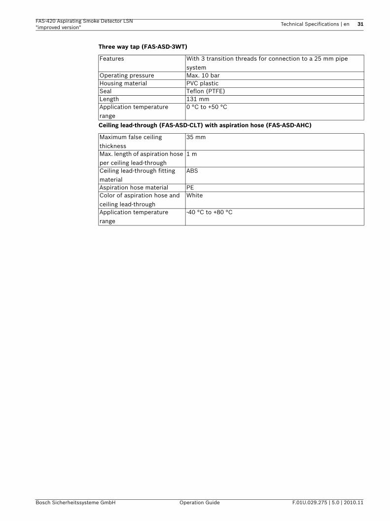
Three way tap (FAS-ASD-3WT)
Ceiling lead-through (FAS-ASD-CLT) with aspiration hose (FAS-ASD-AHC)
Features With 3 transition threads for connection to a 25 mm pipe system
Operating pressure Max. 10 barHousing material PVC plasticSeal Teflon (PTFE)Length 131 mmApplication temperature range
0 °C to +50 °C
Maximum false ceiling thickness
35 mm
Max. length of aspiration hose per ceiling lead-through
1 m
Ceiling lead-through fitting material
ABS
Aspiration hose material PEColor of aspiration hose and ceiling lead-through
White
Application temperature range
-40 °C to +80 °C
32 en | Planning FAS-420 Aspirating Smoke Detector LSN"improved version"
F.01U.029.275 | 5.0 | 2010.11 Operation Guide Bosch Sicherheitssysteme GmbH
3 PlanningBasic information on the relevant topics can be found in– Section 3.1 Regulations, page 32– Section 3.2 Principles of Pipe Planning, page 33– Section 3.3 Airflow Monitoring, page 36– Section 3.4 Defining the Response Sensitivity, page 37– Section 3.5 Planning Limits, page 38.The following sections describe plans with standard requirements for airflow monitoring:– Section 3.6 Standard Pipe Planning, page 39– Section 3.9 Planning for Long Pipe Feed Lines, page 56– Section 3.8 Simplified Pipe Planning, page 52The pipe plan for more sensitive airflow monitoring is described in– Section 3.7 Pipe Planning for Single-Hole Monitoring, page 46.The plan for monitoring air-conditioning ducts is described in– Section 3.11 Planning for Forced Airflow, page 58.The principles for measuring power supply and pipe length are contained in– Section 3.12 Power Supply, page 62.
3.1 RegulationsThe planning regulation below is based on the system limits of FAS-420. The applicable national regulations of the countries concerned must be observed and the plans modified accordingly.The planning for the aspirating smoke detector in accordance with EN 54-20 is described below. The basic conditions are specified in Section 3.1 Regulations. Planning must be carried out in accordance with Section 3.6 Standard Pipe Planning. In addition to 3.6 , special applications are also bound by the restrictions of the planning notes in accordance with Section 3.7 Pipe Planning for Single-Hole Monitoring and the following sections. These must be taken into account from the start in the case of any special planning processes.Planning options in accordance with EN 54-20:Various technical solutions are available to suit different planning criteria. The following table lists the chapters in which the solutions are described.
With regard to the planning regulation below, the applicable national regulations of the countries concerned must be observed and the plans modified accordingly.EN 54-20For VdS systems, compliance is also required with the following guidelines:
Planning criteria Technical solution Principles Restriction
Area monitoring in general
Basic planning Section 3.6
Detection of failure of a single opening
Single-hole monitoring planning
Section 3.6 Section 3.7
Equipment protection/cabinet monitoring
Simplified pipe planning Section 3.6 Section 3.8
Long supply lines Planning with long supply lines
Section 3.6 Section 3.9
Reducing transport time Planning with acceleration openings
Section 3.6 Section 3.10
Ventilation ducts Planning for forced airflow Section 3.6 Section 3.11
FAS-420 Aspirating Smoke Detector LSN "improved version"
Planning | en 33
Bosch Sicherheitssysteme GmbH Operation Guide F.01U.029.275 | 5.0 | 2010.11
– "Guideline for automatic fire detection systems, planning and installation", VdS Schadenverhütung GmbH, Cologne (VdS 2095)
– The guideline "Installation protection for electrical and electronic systems" VdS Schadenverhütung GmbH, Cologne (VdS 2304)
– The "Planning Aspirating Fire Detectors" data sheet from VdS Schadenverhütung GmbH, Cologne (VdS 3435)
The applicable national regulations must also be observed, for example in Germany:– DIN VDE 0833 parts 1 and 2 "Alarm systems for fire, intrusion and hold-up"– Additional provisions for the installation of fire detection systems, which are published
by fire directors of fire departments, by the construction supervision authorities or by the construction law authorities that have only local validity.
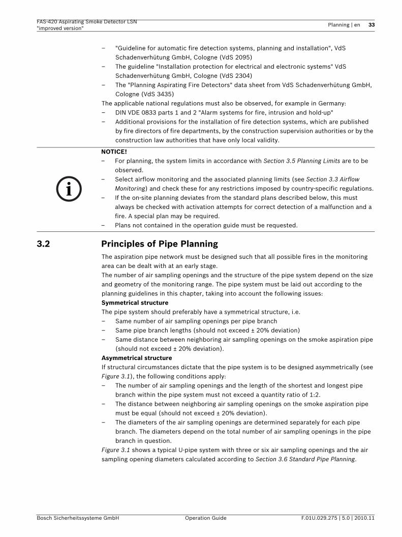
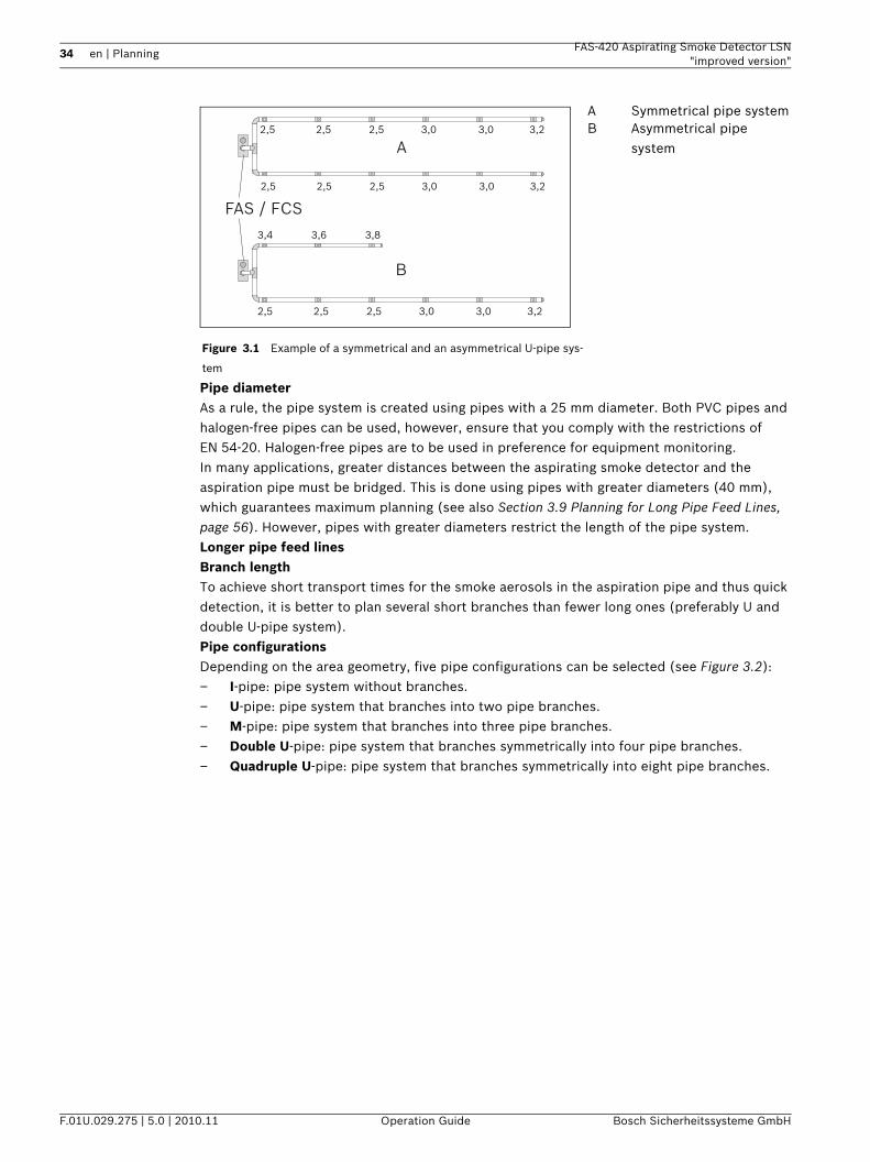
3.2 Principles of Pipe PlanningThe aspiration pipe network must be designed such that all possible fires in the monitoring area can be dealt with at an early stage.The number of air sampling openings and the structure of the pipe system depend on the size and geometry of the monitoring range. The pipe system must be laid out according to the planning guidelines in this chapter, taking into account the following issues:Symmetrical structureThe pipe system should preferably have a symmetrical structure, i.e.– Same number of air sampling openings per pipe branch– Same pipe branch lengths (should not exceed ± 20% deviation)– Same distance between neighboring air sampling openings on the smoke aspiration pipe
(should not exceed ± 20% deviation).Asymmetrical structureIf structural circumstances dictate that the pipe system is to be designed asymmetrically (see Figure 3.1), the following conditions apply:– The number of air sampling openings and the length of the shortest and longest pipe
branch within the pipe system must not exceed a quantity ratio of 1:2.– The distance between neighboring air sampling openings on the smoke aspiration pipe
must be equal (should not exceed ± 20% deviation).– The diameters of the air sampling openings are determined separately for each pipe
branch. The diameters depend on the total number of air sampling openings in the pipe branch in question.
Figure 3.1 shows a typical U-pipe system with three or six air sampling openings and the air sampling opening diameters calculated according to Section 3.6 Standard Pipe Planning.
NOTICE! – For planning, the system limits in accordance with Section 3.5 Planning Limits are to be
observed.– Select airflow monitoring and the associated planning limits (see Section 3.3 Airflow
Monitoring) and check these for any restrictions imposed by country-specific regulations.– If the on-site planning deviates from the standard plans described below, this must
always be checked with activation attempts for correct detection of a malfunction and a fire. A special plan may be required.
– Plans not contained in the operation guide must be requested.
34 en | Planning FAS-420 Aspirating Smoke Detector LSN"improved version"
F.01U.029.275 | 5.0 | 2010.11 Operation Guide Bosch Sicherheitssysteme GmbH
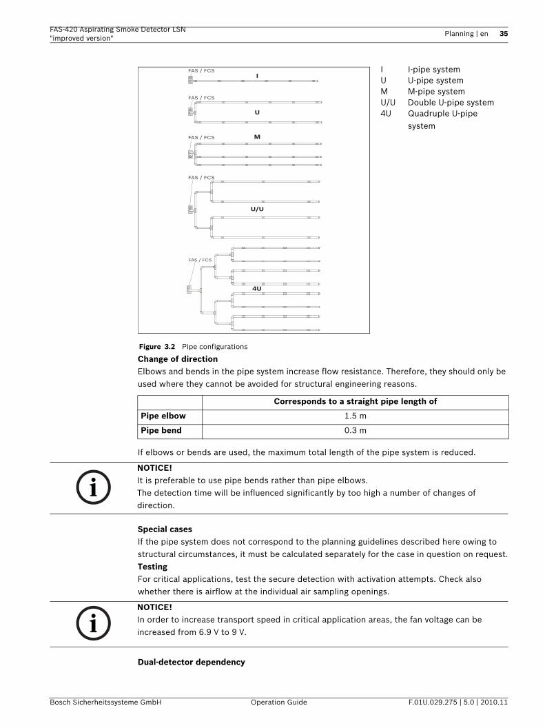
Pipe diameterAs a rule, the pipe system is created using pipes with a 25 mm diameter. Both PVC pipes and halogen-free pipes can be used, however, ensure that you comply with the restrictions of EN 54-20. Halogen-free pipes are to be used in preference for equipment monitoring.In many applications, greater distances between the aspirating smoke detector and the aspiration pipe must be bridged. This is done using pipes with greater diameters (40 mm), which guarantees maximum planning (see also Section 3.9 Planning for Long Pipe Feed Lines, page 56). However, pipes with greater diameters restrict the length of the pipe system.Longer pipe feed linesBranch lengthTo achieve short transport times for the smoke aerosols in the aspiration pipe and thus quick detection, it is better to plan several short branches than fewer long ones (preferably U and double U-pipe system).Pipe configurationsDepending on the area geometry, five pipe configurations can be selected (see Figure 3.2):– I-pipe: pipe system without branches.– U-pipe: pipe system that branches into two pipe branches.– M-pipe: pipe system that branches into three pipe branches.– Double U-pipe: pipe system that branches symmetrically into four pipe branches.– Quadruple U-pipe: pipe system that branches symmetrically into eight pipe branches.
Figure 3.1 Example of a symmetrical and an asymmetrical U-pipe sys-
tem
A Symmetrical pipe systemB Asymmetrical pipe
systemA
B
FAS / FCS
2,5
3,4 3,6 3,8
3,02,5 2,5 3,23,0
2,5 3,02,5 2,5 3,23,0
2,5 3,02,5 2,5 3,23,0
FAS-420 Aspirating Smoke Detector LSN "improved version"
Planning | en 35
Bosch Sicherheitssysteme GmbH Operation Guide F.01U.029.275 | 5.0 | 2010.11
Change of directionElbows and bends in the pipe system increase flow resistance. Therefore, they should only be used where they cannot be avoided for structural engineering reasons.
If elbows or bends are used, the maximum total length of the pipe system is reduced.
Special casesIf the pipe system does not correspond to the planning guidelines described here owing to structural circumstances, it must be calculated separately for the case in question on request.TestingFor critical applications, test the secure detection with activation attempts. Check also whether there is airflow at the individual air sampling openings.
Dual-detector dependency
Figure 3.2 Pipe configurations
I I-pipe systemU U-pipe systemM M-pipe systemU/U Double U-pipe system4U Quadruple U-pipe
system
Corresponds to a straight pipe length of
Pipe elbow 1.5 m
Pipe bend 0.3 m
IFAS / FCS
FAS / FCS
FAS / FCS
U
U/U
FAS / FCS M
FAS / FCS
4U
NOTICE! It is preferable to use pipe bends rather than pipe elbows.The detection time will be influenced significantly by too high a number of changes of direction.
NOTICE! In order to increase transport speed in critical application areas, the fan voltage can be increased from 6.9 V to 9 V.
36 en | Planning FAS-420 Aspirating Smoke Detector LSN"improved version"
F.01U.029.275 | 5.0 | 2010.11 Operation Guide Bosch Sicherheitssysteme GmbH
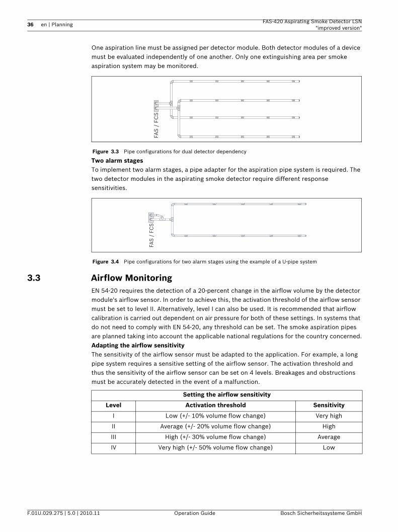
One aspiration line must be assigned per detector module. Both detector modules of a device must be evaluated independently of one another. Only one extinguishing area per smoke aspiration system may be monitored.
Two alarm stagesTo implement two alarm stages, a pipe adapter for the aspiration pipe system is required. The two detector modules in the aspirating smoke detector require different response sensitivities.
3.3 Airflow MonitoringEN 54-20 requires the detection of a 20-percent change in the airflow volume by the detector module's airflow sensor. In order to achieve this, the activation threshold of the airflow sensor must be set to level II. Alternatively, level I can also be used. It is recommended that airflow calibration is carried out dependent on air pressure for both of these settings. In systems that do not need to comply with EN 54-20, any threshold can be set. The smoke aspiration pipes are planned taking into account the applicable national regulations for the country concerned.Adapting the airflow sensitivityThe sensitivity of the airflow sensor must be adapted to the application. For example, a long pipe system requires a sensitive setting of the airflow sensor. The activation threshold and thus the sensitivity of the airflow sensor can be set on 4 levels. Breakages and obstructions must be accurately detected in the event of a malfunction.
Figure 3.3 Pipe configurations for dual detector dependency
Figure 3.4 Pipe configurations for two alarm stages using the example of a U-pipe system
FAS
/ F
CS
FAS
/ F
CS
Setting the airflow sensitivity
Level Activation threshold Sensitivity
I Low (+/- 10% volume flow change) Very high
II Average (+/- 20% volume flow change) High
III High (+/- 30% volume flow change) Average
IV Very high (+/- 50% volume flow change) Low
FAS-420 Aspirating Smoke Detector LSN "improved version"
Planning | en 37
Bosch Sicherheitssysteme GmbH Operation Guide F.01U.029.275 | 5.0 | 2010.11
Dynamic airflow sensorsThe airflow monitoring of the unit makes it possible to detect breaks at the end of pipes and identify sudden obstruction of individual air sampling openings (e.g. following tampering with the pipe system). Because these dynamic airflow sensors are only active if level I was selected for the airflow monitoring, the points outlined under "Level I restrictions" must be taken into consideration.RestrictionsAirflow monitoring may only be set to level I if – planning was carried out in accordance with "single-hole monitoring" (see Chapter 4.3.1
"Pipe Planning for Single-Hole Monitoring"), – the airflow sensor was calibrated dependent on the air pressure (see Chapter 7.1.2
"Airflow Calibration according to Air Pressure") – and no larger airflow fluctuations can occur.Air pressure differencesThere must be equal air pressure along the length of the aspiration pipe.
3.4 Defining the Response SensitivityThe sensitivity of smoke aspiration systems can be divided into certain fire sensitivity classes in accordance with EN 54-20. These fire sensitivity classes describe specific examples of ways in which the systems can be applied. The permissible system plans given in Section 3.6 can be determined for each classification.Smoke aspiration systems with a higher fire sensitivity class according to EN 54-20 also satisfy the requirements of the lower classes.
Level I II III IV
Complies with EN 54-20
Activation threshold Small Average Large Very large
Sensitivity Very high High Average Low
NOTICE! Selection of the largest possible, precisely still-approved level is recommended.
NOTICE! If the aspirating smoke detectors and the pipe system are positioned in areas with different air pressures, the air aspirated by the FAS-420 must be returned to the pressure area of the pipe system (see Section 2.6.4 Air-Return Pipe for Pressure Areas and Atmospheric Loads, page 24).
Class Description Application example
A Aspirating smoke detector with extremely high sensitivity
Very early detection: significant smoke dilution through air conditioning in IT
areas
B Aspirating smoke detector with increased sensitivity
Early detection: significant time gains thanks to very
early fire detection (without air condition)
C Smoke aspiration system with normal sensitivity
Normal detection: fire detection with the advantages of
smoke aspiration systems
38 en | Planning FAS-420 Aspirating Smoke Detector LSN"improved version"
F.01U.029.275 | 5.0 | 2010.11 Operation Guide Bosch Sicherheitssysteme GmbH
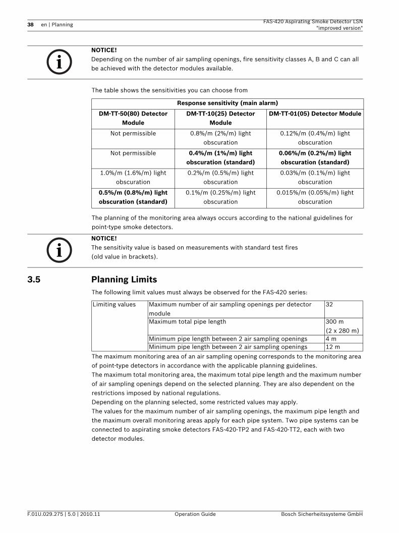
The table shows the sensitivities you can choose from
The planning of the monitoring area always occurs according to the national guidelines for point-type smoke detectors.
3.5 Planning LimitsThe following limit values must always be observed for the FAS-420 series:
The maximum monitoring area of an air sampling opening corresponds to the monitoring area of point-type detectors in accordance with the applicable planning guidelines.The maximum total monitoring area, the maximum total pipe length and the maximum number of air sampling openings depend on the selected planning. They are also dependent on the restrictions imposed by national regulations.Depending on the planning selected, some restricted values may apply.The values for the maximum number of air sampling openings, the maximum pipe length and the maximum overall monitoring areas apply for each pipe system. Two pipe systems can be connected to aspirating smoke detectors FAS-420-TP2 and FAS-420-TT2, each with two detector modules.
NOTICE! Depending on the number of air sampling openings, fire sensitivity classes A, B and C can all be achieved with the detector modules available.
Response sensitivity (main alarm)
DM-TT-50(80) Detector Module
DM-TT-10(25) Detector Module
DM-TT-01(05) Detector Module
Not permissible 0.8%/m (2%/m) light obscuration
0.12%/m (0.4%/m) light obscuration
Not permissible 0.4%/m (1%/m) light obscuration (standard)
0.06%/m (0.2%/m) light obscuration (standard)
1.0%/m (1.6%/m) light obscuration
0.2%/m (0.5%/m) light obscuration
0.03%/m (0.1%/m) light obscuration
0.5%/m (0.8%/m) light obscuration (standard)
0.1%/m (0.25%/m) light obscuration
0.015%/m (0.05%/m) light obscuration
NOTICE! The sensitivity value is based on measurements with standard test fires (old value in brackets).
Limiting values Maximum number of air sampling openings per detector module
32
Maximum total pipe length 300 m(2 x 280 m)
Minimum pipe length between 2 air sampling openings 4 mMinimum pipe length between 2 air sampling openings 12 m
FAS-420 Aspirating Smoke Detector LSN "improved version"
Planning | en 39
Bosch Sicherheitssysteme GmbH Operation Guide F.01U.029.275 | 5.0 | 2010.11
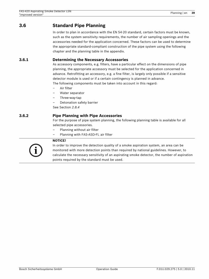
3.6 Standard Pipe PlanningIn order to plan in accordance with the EN 54-20 standard, certain factors must be known, such as the system sensitivity requirements, the number of air sampling openings and the accessories needed for the application concerned. These factors can be used to determine the appropriate standard-compliant construction of the pipe system using the following chapter and the planning table in the appendix.
3.6.1 Determining the Necessary AccessoriesAs accessory components, e.g. filters, have a particular effect on the dimensions of pipe planning, the appropriate accessory must be selected for the application concerned in advance. Retrofitting an accessory, e.g. a fine filter, is largely only possible if a sensitive detector module is used or if a certain contingency is planned in advance.The following components must be taken into account in this regard:– Air filter– Water separator– Three-way-tap– Detonation safety barrierSee Section 2.8.4
3.6.2 Pipe Planning with Pipe AccessoriesFor the purpose of pipe system planning, the following planning table is available for all selected pipe accessories.– Planning without air filter– Planning with FAS-ASD-FL air filter
NOTICE! In order to improve the detection quality of a smoke aspiration system, an area can be monitored with more detection points than required by national guidelines. However, to calculate the necessary sensitivity of an aspirating smoke detector, the number of aspiration points required by the standard must be used.
40 en | Planning FAS-420 Aspirating Smoke Detector LSN"improved version"
F.01U.029.275 | 5.0 | 2010.11 Operation Guide Bosch Sicherheitssysteme GmbH
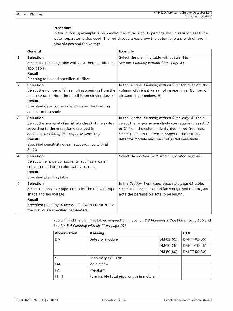
ProcedureIn the following example, a plan without air filter with 8 openings should satisfy class B if a water separator is also used. The red shaded areas show the potential plans with different pipe shapes and fan voltage.
You will find the planning tables in question in Section 8.3 Planning without filter, page 105 and Section 8.4 Planning with air filter, page 107.
General Example
1. Selection:Select the planning table with or without air filter, as applicable.Result:Planning table and specified air filter
Select the planning table without air filter, Section Planning without filter, page 41
2. Selection:Select the number of air sampling openings from the planning table. Note the possible sensitivity classes.Result:Specified detector module with specified setting and alarm threshold
In the Section Planning without filter table, select the column with eight air sampling openings (Number of air sampling openings, 8)
3. Selection:Select the sensitivity (sensitivity class) of the system according to the gradation described in Section 3.4 Defining the Response Sensitivity.Result:Specified sensitivity class in accordance with EN 54-20
In the Section Planning without filter, page 41 table, select the response sensitivity you require (class A, B or C) from the column highlighted in red. You must select the class that corresponds to the installed detector module and the configured sensitivity.
4. Selection:Select other pipe components, such as a water separator and detonation safety barrier.Result:Specified planning table
Select the Section With water separator, page 41 .
5. Selection:Select the possible pipe length for the relevant pipe shape and fan voltage.Result:Specified planning in accordance with EN 54-20 for the previously specified parameters
In the Section With water separator, page 41 table, select the pipe shape and fan voltage you require, and note the permissible total pipe length.
Abbreviation Meaning CTN
DM Detector module DM-01(05) DM-TT-01(05)
DM-10(25) DM-TT-10(25)
DM-50(80) DM-TT-50(80)
S Sensitivity (% LT/m)
MA Main alarm
PA Pre-alarm
l [m] Permissible total pipe length in meters
FAS-420 Aspirating Smoke Detector LSN "improved version"
Planning | en 41
Bosch Sicherheitssysteme GmbH Operation Guide F.01U.029.275 | 5.0 | 2010.11
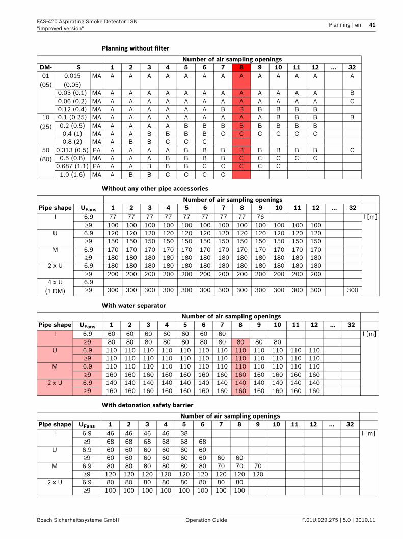
Planning without filter
Without any other pipe accessories
With water separator
With detonation safety barrier
Number of air sampling openingsDM- S 1 2 3 4 5 6 7 8 9 10 11 12 … 3201
(05)0.015 (0.05)
MA A A A A A A A A A A A A A
0.03 (0.1) MA A A A A A A A A A A A A B0.06 (0.2) MA A A A A A A A A A A A A C0.12 (0.4) MA A A A A A A B B B B B B
10 (25)
0.1 (0.25) MA A A A A A A A A A B B B B0.2 (0.5) MA A A A A B B B B B B B B0.4 (1) MA A A B B B B C C C C C C0.8 (2) MA A B B C C C
50 (80)
0.313 (0.5) PA A A A A B B B B B B B B C0.5 (0.8) MA A A A B B B B C C C C C
0.687 (1.1) PA A A B B B C C C C C1.0 (1.6) MA A B B C C C C
Number of air sampling openingsPipe shape UFans 1 2 3 4 5 6 7 8 9 10 11 12 … 32
I 6.9 77 77 77 77 77 77 77 77 76 l [m]≥9 100 100 100 100 100 100 100 100 100 100 100 100
U 6.9 120 120 120 120 120 120 120 120 120 120 120 120≥9 150 150 150 150 150 150 150 150 150 150 150 150
M 6.9 170 170 170 170 170 170 170 170 170 170 170 170≥9 180 180 180 180 180 180 180 180 180 180 180 180
2 x U 6.9 180 180 180 180 180 180 180 180 180 180 180 180≥9 200 200 200 200 200 200 200 200 200 200 200 200
4 x U (1 DM)
6.9≥9 300 300 300 300 300 300 300 300 300 300 300 300 300
Number of air sampling openingsPipe shape UFans 1 2 3 4 5 6 7 8 9 10 11 12 … 32
I 6.9 60 60 60 60 60 60 60 l [m]≥9 80 80 80 80 80 80 80 80 80 80
U 6.9 110 110 110 110 110 110 110 110 110 110 110 110≥9 110 110 110 110 110 110 110 110 110 110 110 110
M 6.9 110 110 110 110 110 110 110 110 110 110 110 110≥9 160 160 160 160 160 160 160 160 160 160 160 160
2 x U 6.9 140 140 140 140 140 140 140 140 140 140 140 140≥9 160 160 160 160 160 160 160 160 160 160 160 160
Number of air sampling openingsPipe shape UFans 1 2 3 4 5 6 7 8 9 10 11 12 … 32
I 6.9 46 46 46 46 38 l [m]≥9 68 68 68 68 68 68
U 6.9 60 60 60 60 60 60≥9 60 60 60 60 60 60 60 60
M 6.9 80 80 80 80 80 80 70 70 70≥9 120 120 120 120 120 120 120 120 120
2 x U 6.9 80 80 80 80 80 80 80 80≥9 100 100 100 100 100 100 100 100
42 en | Planning FAS-420 Aspirating Smoke Detector LSN"improved version"
F.01U.029.275 | 5.0 | 2010.11 Operation Guide Bosch Sicherheitssysteme GmbH
ResultsThe following modules can be used with the relevant settings for class B or A:– 0.015% LT/m (0.05% LT/m) module – with a sensitivity
of min. 0.12% LT/m (0.4% LT/m)– 0.1% LT/m (0.25% LT/m) module – with a sensitivity
of min. 0.2% LT/m (0.5% LT/m)– 0.5% LT/m (0.8% LT/m) module – with setting 0.5% LT/m (0.8% LT/m)System parameters possible:– I-pipe system
– 9 V fan voltage, max. 80 m total pipe length for U-pipe system– U-pipe system
– 6.9 V fan voltage, max. 110 m total pipe length– 9 V fan voltage, max. 110 m total pipe length
– M-pipe system– 6.9 V fan voltage, max. 110 m total pipe length– 9 V fan voltage, max. 160 m total pipe length
– Double U-pipe system– 6.9 V fan voltage, max. 140 m total pipe length– 9 V fan voltage, max. 160 m total pipe length
NOTICE! The sensitivity value is based on measurements with standard test fires (old value in brackets).
FAS-420 Aspirating Smoke Detector LSN "improved version"
Planning | en 43
Bosch Sicherheitssysteme GmbH Operation Guide F.01U.029.275 | 5.0 | 2010.11
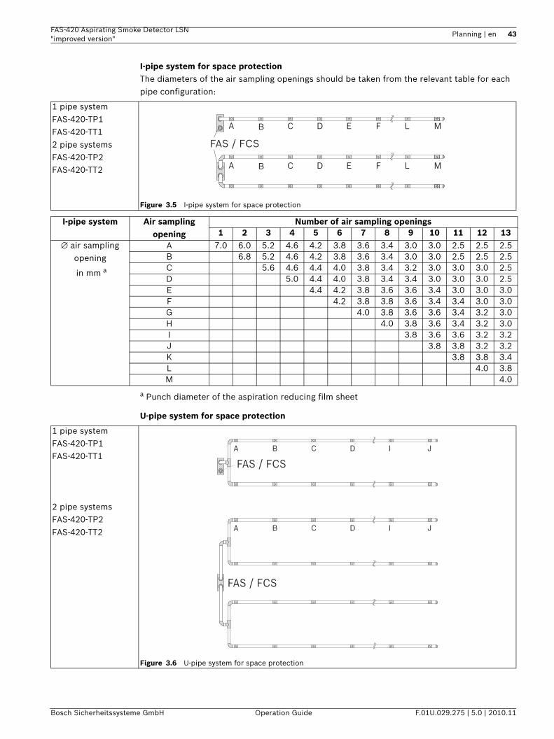
I-pipe system for space protectionThe diameters of the air sampling openings should be taken from the relevant table for each pipe configuration:
a Punch diameter of the aspiration reducing film sheet
U-pipe system for space protection
1 pipe system FAS-420-TP1FAS-420-TT12 pipe systems FAS-420-TP2FAS-420-TT2
Figure 3.5 I-pipe system for space protection
FAS / FCS
A B C D E L MF
A B C D E L MF
I-pipe system Air sampling opening
Number of air sampling openings1 2 3 4 5 6 7 8 9 10 11 12 13
∅ air sampling opening
in mm a
A 7.0 6.0 5.2 4.6 4.2 3.8 3.6 3.4 3.0 3.0 2.5 2.5 2.5B 6.8 5.2 4.6 4.2 3.8 3.6 3.4 3.0 3.0 2.5 2.5 2.5C 5.6 4.6 4.4 4.0 3.8 3.4 3.2 3.0 3.0 3.0 2.5D 5.0 4.4 4.0 3.8 3.4 3.4 3.0 3.0 3.0 2.5E 4.4 4.2 3.8 3.6 3.6 3.4 3.0 3.0 3.0F 4.2 3.8 3.8 3.6 3.4 3.4 3.0 3.0G 4.0 3.8 3.6 3.6 3.4 3.2 3.0H 4.0 3.8 3.6 3.4 3.2 3.0I 3.8 3.6 3.6 3.2 3.2J 3.8 3.8 3.2 3.2K 3.8 3.8 3.4L 4.0 3.8M 4.0
1 pipe system FAS-420-TP1FAS-420-TT1
2 pipe systems FAS-420-TP2FAS-420-TT2
Figure 3.6 U-pipe system for space protection
FAS / FCS
FAS / FCS
A B C D I J
A B C D I J
44 en | Planning FAS-420 Aspirating Smoke Detector LSN"improved version"
F.01U.029.275 | 5.0 | 2010.11 Operation Guide Bosch Sicherheitssysteme GmbH
a Punch diameter of the aspiration reducing film sheet
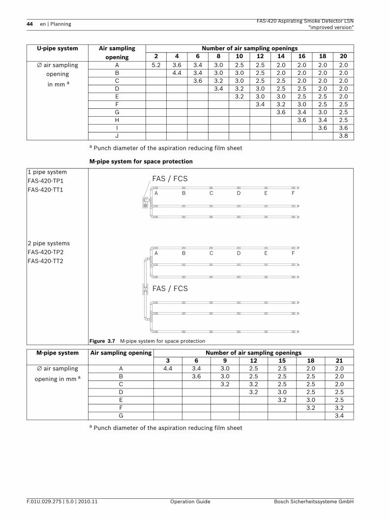
M-pipe system for space protection
a Punch diameter of the aspiration reducing film sheet
U-pipe system Air sampling opening
Number of air sampling openings2 4 6 8 10 12 14 16 18 20
∅ air sampling opening
in mm a
A 5.2 3.6 3.4 3.0 2.5 2.5 2.0 2.0 2.0 2.0B 4.4 3.4 3.0 3.0 2.5 2.0 2.0 2.0 2.0C 3.6 3.2 3.0 2.5 2.5 2.0 2.0 2.0D 3.4 3.2 3.0 2.5 2.5 2.0 2.0E 3.2 3.0 3.0 2.5 2.5 2.0F 3.4 3.2 3.0 2.5 2.5G 3.6 3.4 3.0 2.5H 3.6 3.4 2.5I 3.6 3.6J 3.8
1 pipe system FAS-420-TP1FAS-420-TT1
2 pipe systems FAS-420-TP2FAS-420-TT2
Figure 3.7 M-pipe system for space protection
A B C D E F
A B C D E F
FAS / FCS
FAS / FCS
M-pipe system Air sampling opening Number of air sampling openings3 6 9 12 15 18 21
∅ air sampling
opening in mm a
A 4.4 3.4 3.0 2.5 2.5 2.0 2.0B 3.6 3.0 2.5 2.5 2.5 2.0C 3.2 3.2 2.5 2.5 2.0D 3.2 3.0 2.5 2.5E 3.2 3.0 2.5F 3.2 3.2G 3.4
FAS-420 Aspirating Smoke Detector LSN "improved version"
Planning | en 45
Bosch Sicherheitssysteme GmbH Operation Guide F.01U.029.275 | 5.0 | 2010.11
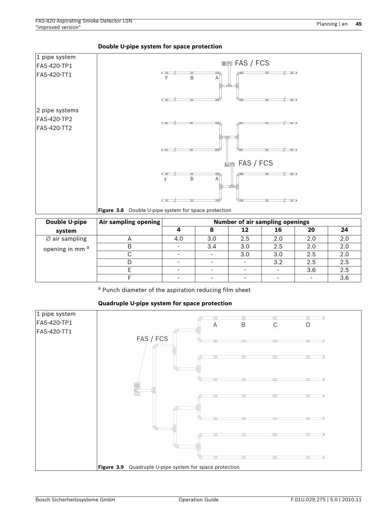
Double U-pipe system for space protection
a Punch diameter of the aspiration reducing film sheet
Quadruple U-pipe system for space protection
1 pipe system FAS-420-TP1FAS-420-TT1
2 pipe systems FAS-420-TP2FAS-420-TT2
Figure 3.8 Double U-pipe system for space protection
FAS / FCS
FAS / FCS
F
F
B
B
A
A
Double U-pipe system
Air sampling opening Number of air sampling openings4 8 12 16 20 24
∅ air sampling
opening in mm a
A 4.0 3.0 2.5 2.0 2.0 2.0B - 3.4 3.0 2.5 2.0 2.0C - - 3.0 3.0 2.5 2.0D - - - 3.2 2.5 2.5E - - - - 3.6 2.5F - - - - - 3.6
1 pipe system FAS-420-TP1FAS-420-TT1
Figure 3.9 Quadruple U-pipe system for space protection
A B C D
FAS / FCS
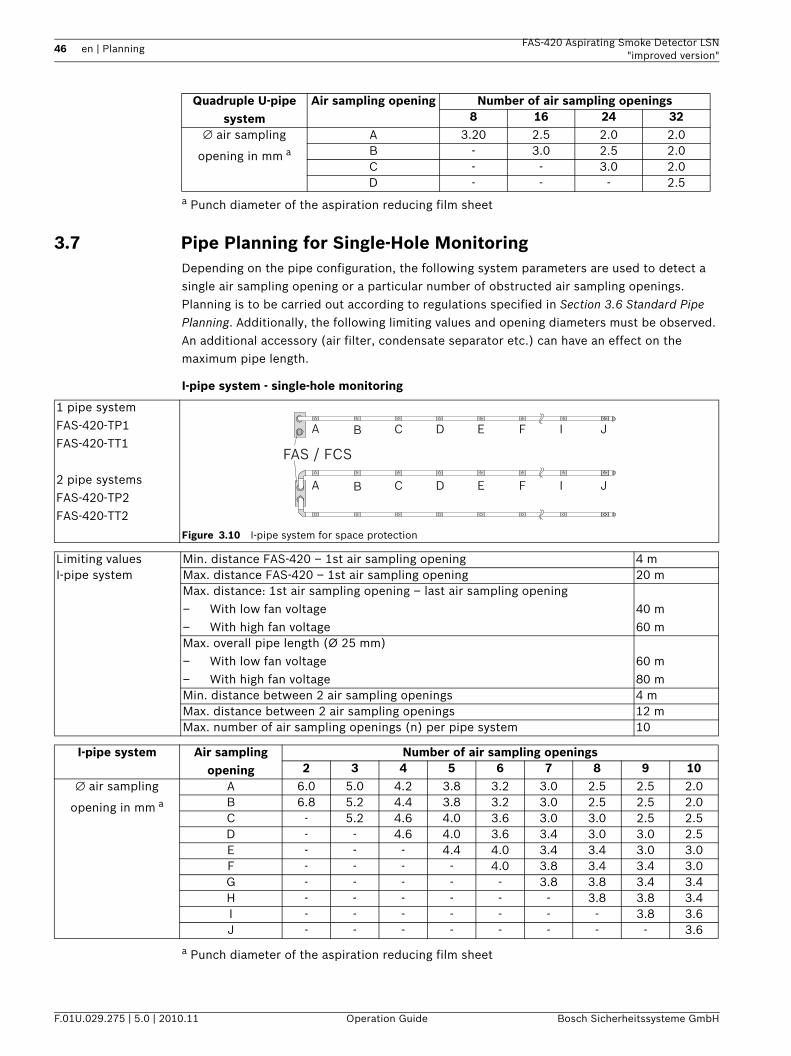
46 en | Planning FAS-420 Aspirating Smoke Detector LSN"improved version"
F.01U.029.275 | 5.0 | 2010.11 Operation Guide Bosch Sicherheitssysteme GmbH
a Punch diameter of the aspiration reducing film sheet
3.7 Pipe Planning for Single-Hole MonitoringDepending on the pipe configuration, the following system parameters are used to detect a single air sampling opening or a particular number of obstructed air sampling openings. Planning is to be carried out according to regulations specified in Section 3.6 Standard Pipe Planning. Additionally, the following limiting values and opening diameters must be observed. An additional accessory (air filter, condensate separator etc.) can have an effect on the maximum pipe length.
I-pipe system - single-hole monitoring
a Punch diameter of the aspiration reducing film sheet
Quadruple U-pipe system
Air sampling opening Number of air sampling openings8 16 24 32
∅ air sampling
opening in mm a
A 3.20 2.5 2.0 2.0B - 3.0 2.5 2.0C - - 3.0 2.0D - - - 2.5
1 pipe system FAS-420-TP1FAS-420-TT1
2 pipe systems FAS-420-TP2FAS-420-TT2
Figure 3.10 I-pipe system for space protection
FAS / FCS
A B C D E I JF
A B C D E I JF
Limiting values Min. distance FAS-420 – 1st air sampling opening 4 mI-pipe system Max. distance FAS-420 – 1st air sampling opening 20 m
Max. distance: 1st air sampling opening – last air sampling opening– With low fan voltage– With high fan voltage
40 m60 m
Max. overall pipe length (Ø 25 mm)– With low fan voltage– With high fan voltage
60 m80 m
Min. distance between 2 air sampling openings 4 mMax. distance between 2 air sampling openings 12 mMax. number of air sampling openings (n) per pipe system 10
I-pipe system Air sampling opening
Number of air sampling openings2 3 4 5 6 7 8 9 10
∅ air sampling
opening in mm a
A 6.0 5.0 4.2 3.8 3.2 3.0 2.5 2.5 2.0B 6.8 5.2 4.4 3.8 3.2 3.0 2.5 2.5 2.0C - 5.2 4.6 4.0 3.6 3.0 3.0 2.5 2.5D - - 4.6 4.0 3.6 3.4 3.0 3.0 2.5E - - - 4.4 4.0 3.4 3.4 3.0 3.0F - - - - 4.0 3.8 3.4 3.4 3.0G - - - - - 3.8 3.8 3.4 3.4H - - - - - - 3.8 3.8 3.4I - - - - - - - 3.8 3.6J - - - - - - - - 3.6
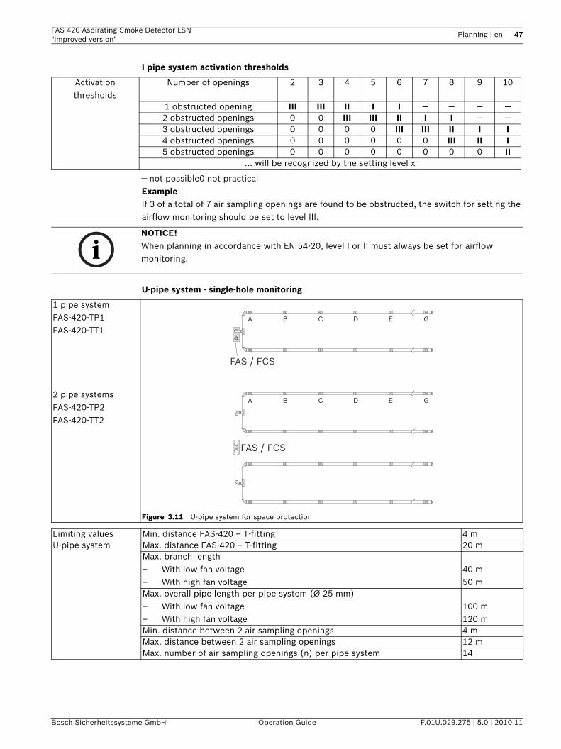
FAS-420 Aspirating Smoke Detector LSN "improved version"
Planning | en 47
Bosch Sicherheitssysteme GmbH Operation Guide F.01U.029.275 | 5.0 | 2010.11
I pipe system activation thresholds
— not possible0 not practicalExampleIf 3 of a total of 7 air sampling openings are found to be obstructed, the switch for setting the airflow monitoring should be set to level III.
U-pipe system - single-hole monitoring
Activation thresholds
Number of openings 2 3 4 5 6 7 8 9 10
1 obstructed opening III III II I I — — — —2 obstructed openings 0 0 III III II I I — —3 obstructed openings 0 0 0 0 III III II I I4 obstructed openings 0 0 0 0 0 0 III II I5 obstructed openings 0 0 0 0 0 0 0 0 II
… will be recognized by the setting level x
NOTICE! When planning in accordance with EN 54-20, level I or II must always be set for airflow monitoring.
1 pipe systemFAS-420-TP1FAS-420-TT1
2 pipe systems FAS-420-TP2FAS-420-TT2
Figure 3.11 U-pipe system for space protection
FAS / FCS
FAS / FCS
A B C D E G
A B C D E G
Limiting values Min. distance FAS-420 – T-fitting 4 mU-pipe system Max. distance FAS-420 – T-fitting 20 m
Max. branch length– With low fan voltage– With high fan voltage
40 m50 m
Max. overall pipe length per pipe system (Ø 25 mm)– With low fan voltage– With high fan voltage
100 m120 m
Min. distance between 2 air sampling openings 4 mMax. distance between 2 air sampling openings 12 mMax. number of air sampling openings (n) per pipe system 14
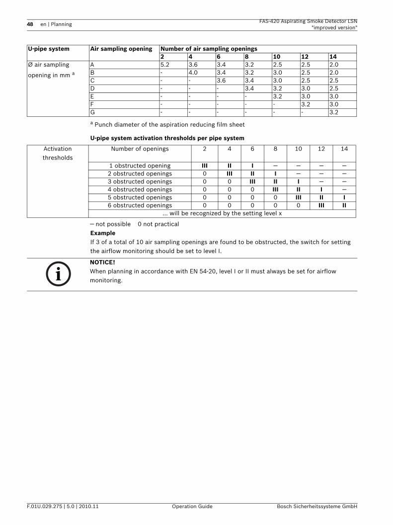
48 en | Planning FAS-420 Aspirating Smoke Detector LSN"improved version"
F.01U.029.275 | 5.0 | 2010.11 Operation Guide Bosch Sicherheitssysteme GmbH
a Punch diameter of the aspiration reducing film sheet
U-pipe system activation thresholds per pipe system
— not possible 0 not practicalExampleIf 3 of a total of 10 air sampling openings are found to be obstructed, the switch for setting the airflow monitoring should be set to level I.
U-pipe system Air sampling opening Number of air sampling openings2 4 6 8 10 12 14
Ø air sampling
opening in mm aA 5.2 3.6 3.4 3.2 2.5 2.5 2.0B - 4.0 3.4 3.2 3.0 2.5 2.0C - - 3.6 3.4 3.0 2.5 2.5D - - - 3.4 3.2 3.0 2.5E - - - - 3.2 3.0 3.0F - - - - - 3.2 3.0G - - - - - - 3.2
Activation thresholds
Number of openings 2 4 6 8 10 12 14
1 obstructed opening III II I — — — —2 obstructed openings 0 III II I — — —3 obstructed openings 0 0 III II I — —4 obstructed openings 0 0 0 III II I —5 obstructed openings 0 0 0 0 III II I6 obstructed openings 0 0 0 0 0 III II
… will be recognized by the setting level x
NOTICE! When planning in accordance with EN 54-20, level I or II must always be set for airflow monitoring.
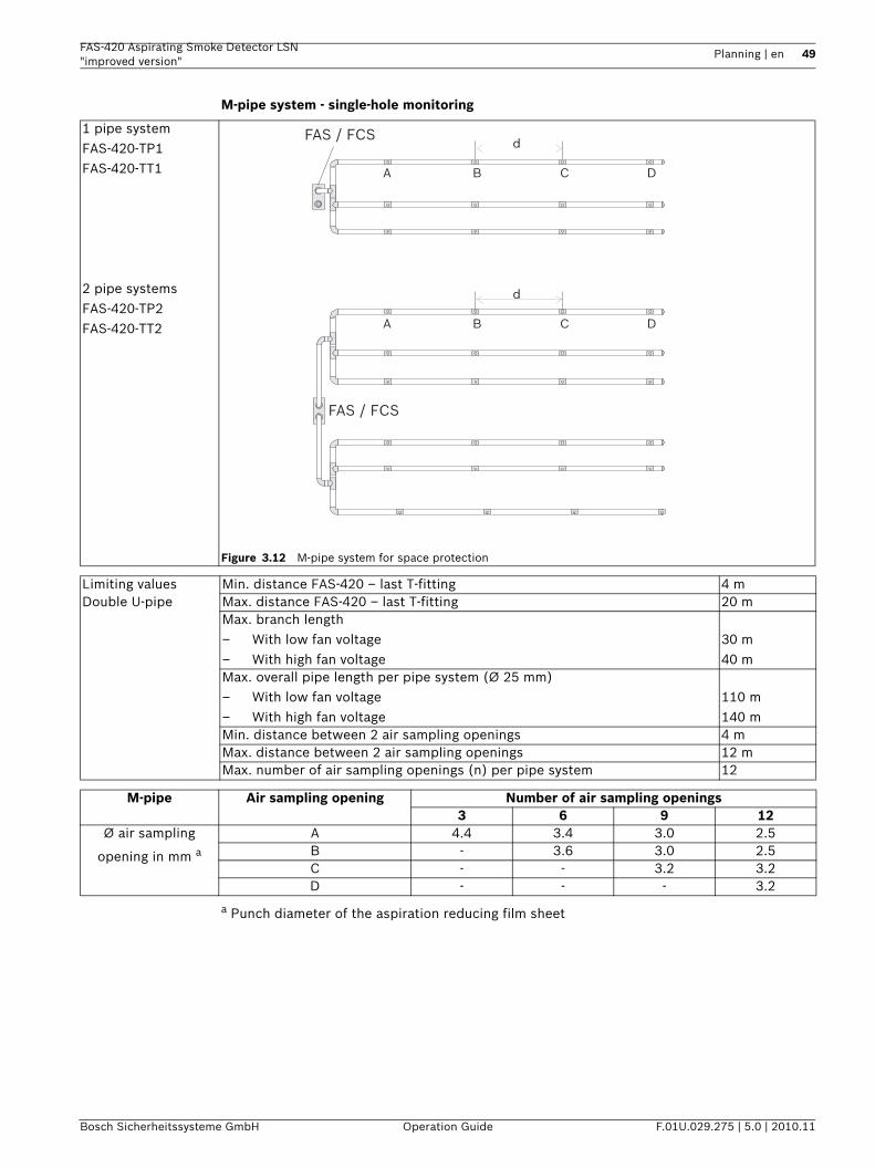
FAS-420 Aspirating Smoke Detector LSN "improved version"
Planning | en 49
Bosch Sicherheitssysteme GmbH Operation Guide F.01U.029.275 | 5.0 | 2010.11
M-pipe system - single-hole monitoring
a Punch diameter of the aspiration reducing film sheet
1 pipe systemFAS-420-TP1FAS-420-TT1
2 pipe systems FAS-420-TP2FAS-420-TT2
Figure 3.12 M-pipe system for space protection
d
d
A B C D
A B C D
FAS / FCS
FAS / FCS
Limiting values Min. distance FAS-420 – last T-fitting 4 mDouble U-pipe Max. distance FAS-420 – last T-fitting 20 m
Max. branch length– With low fan voltage– With high fan voltage
30 m40 m
Max. overall pipe length per pipe system (Ø 25 mm)– With low fan voltage– With high fan voltage
110 m140 m
Min. distance between 2 air sampling openings 4 mMax. distance between 2 air sampling openings 12 mMax. number of air sampling openings (n) per pipe system 12
M-pipe Air sampling opening Number of air sampling openings3 6 9 12
Ø air sampling
opening in mm aA 4.4 3.4 3.0 2.5B - 3.6 3.0 2.5C - - 3.2 3.2D - - - 3.2
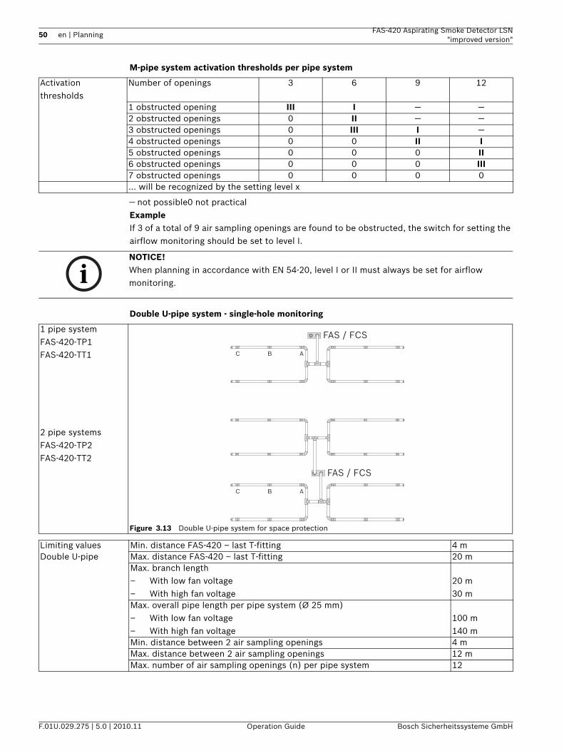
50 en | Planning FAS-420 Aspirating Smoke Detector LSN"improved version"
F.01U.029.275 | 5.0 | 2010.11 Operation Guide Bosch Sicherheitssysteme GmbH
M-pipe system activation thresholds per pipe system
— not possible0 not practicalExampleIf 3 of a total of 9 air sampling openings are found to be obstructed, the switch for setting the airflow monitoring should be set to level I.
Double U-pipe system - single-hole monitoring
Activation thresholds
Number of openings 3 6 9 12
1 obstructed opening III I — —2 obstructed openings 0 II — —3 obstructed openings 0 III I —4 obstructed openings 0 0 II I5 obstructed openings 0 0 0 II6 obstructed openings 0 0 0 III7 obstructed openings 0 0 0 0… will be recognized by the setting level x
NOTICE! When planning in accordance with EN 54-20, level I or II must always be set for airflow monitoring.
1 pipe systemFAS-420-TP1FAS-420-TT1
2 pipe systems FAS-420-TP2FAS-420-TT2
Figure 3.13 Double U-pipe system for space protection
FAS / FCS
FAS / FCS
C
C
B
B
A
A
Limiting values Min. distance FAS-420 – last T-fitting 4 mDouble U-pipe Max. distance FAS-420 – last T-fitting 20 m
Max. branch length– With low fan voltage– With high fan voltage
20 m30 m
Max. overall pipe length per pipe system (Ø 25 mm)– With low fan voltage– With high fan voltage
100 m140 m
Min. distance between 2 air sampling openings 4 mMax. distance between 2 air sampling openings 12 mMax. number of air sampling openings (n) per pipe system 12
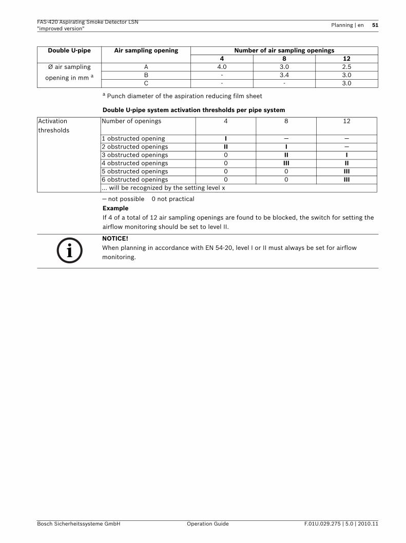
FAS-420 Aspirating Smoke Detector LSN "improved version"
Planning | en 51
Bosch Sicherheitssysteme GmbH Operation Guide F.01U.029.275 | 5.0 | 2010.11
a Punch diameter of the aspiration reducing film sheet
Double U-pipe system activation thresholds per pipe system
— not possible 0 not practicalExampleIf 4 of a total of 12 air sampling openings are found to be blocked, the switch for setting the airflow monitoring should be set to level II.
Double U-pipe Air sampling opening Number of air sampling openings4 8 12
Ø air sampling
opening in mm aA 4.0 3.0 2.5B - 3.4 3.0C - - 3.0
Activation thresholds
Number of openings 4 8 12
1 obstructed opening I — —2 obstructed openings II I —3 obstructed openings 0 II I4 obstructed openings 0 III II5 obstructed openings 0 0 III6 obstructed openings 0 0 III… will be recognized by the setting level x
NOTICE! When planning in accordance with EN 54-20, level I or II must always be set for airflow monitoring.
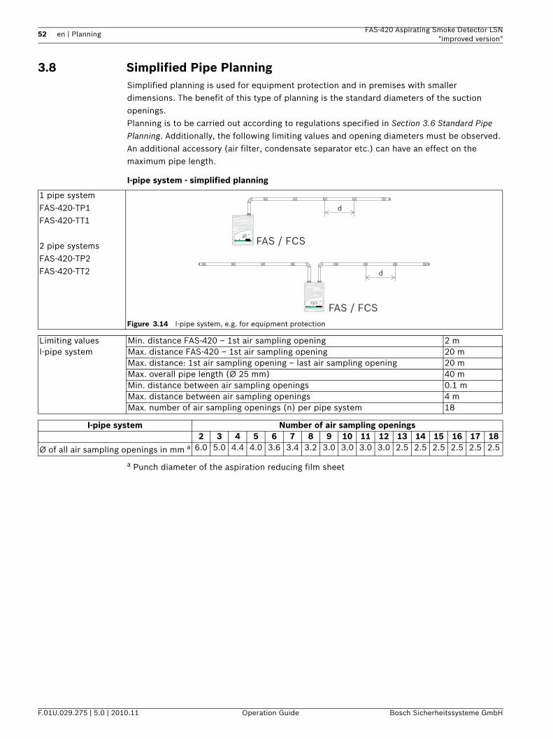
52 en | Planning FAS-420 Aspirating Smoke Detector LSN"improved version"
F.01U.029.275 | 5.0 | 2010.11 Operation Guide Bosch Sicherheitssysteme GmbH
3.8 Simplified Pipe PlanningSimplified planning is used for equipment protection and in premises with smaller dimensions. The benefit of this type of planning is the standard diameters of the suction openings.Planning is to be carried out according to regulations specified in Section 3.6 Standard Pipe Planning. Additionally, the following limiting values and opening diameters must be observed. An additional accessory (air filter, condensate separator etc.) can have an effect on the maximum pipe length.
I-pipe system - simplified planning
a Punch diameter of the aspiration reducing film sheet
1 pipe systemFAS-420-TP1FAS-420-TT1
2 pipe systems FAS-420-TP2FAS-420-TT2
Figure 3.14 I-pipe system, e.g. for equipment protection
FAS / FCS
FAS / FCS
d
d
i 12345678910
i
12
12345678910
12345678910
Limiting values Min. distance FAS-420 – 1st air sampling opening 2 mI-pipe system Max. distance FAS-420 – 1st air sampling opening 20 m
Max. distance: 1st air sampling opening – last air sampling opening 20 mMax. overall pipe length (Ø 25 mm) 40 mMin. distance between air sampling openings 0.1 mMax. distance between air sampling openings 4 mMax. number of air sampling openings (n) per pipe system 18
I-pipe system Number of air sampling openings2 3 4 5 6 7 8 9 10 11 12 13 14 15 16 17 18
Ø of all air sampling openings in mm a 6.0 5.0 4.4 4.0 3.6 3.4 3.2 3.0 3.0 3.0 3.0 2.5 2.5 2.5 2.5 2.5 2.5
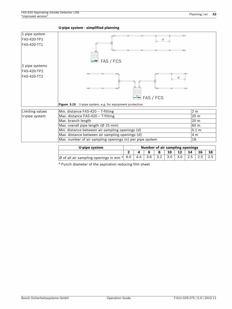
FAS-420 Aspirating Smoke Detector LSN "improved version"
Planning | en 53
Bosch Sicherheitssysteme GmbH Operation Guide F.01U.029.275 | 5.0 | 2010.11
U-pipe system - simplified planning
a Punch diameter of the aspiration reducing film sheet
1 pipe systemFAS-420-TP1FAS-420-TT1
2 pipe systems FAS-420-TP2FAS-420-TT2
Figure 3.15 U-pipe system, e.g. for equipment protection
FAS / FCS
FAS / FCS
d
d
i
12
12
34
56
78
91 0
12
34
56
78
91 0
i1
234
567
891 0
Limiting values Min. distance FAS-420 – T-fitting 2 mU-pipe system Max. distance FAS-420 – T-fitting 20 m
Max. branch length 20 mMax. overall pipe length (Ø 25 mm) 60 mMin. distance between air sampling openings (d) 0.1 mMax. distance between air sampling openings (d) 4 mMax. number of air sampling openings (n) per pipe system 18
U-pipe system Number of air sampling openings2 4 6 8 10 12 14 16 18
Ø of all air sampling openings in mm a 6.0 4.4 3.6 3.2 3.0 3.0 2.5 2.5 2.5
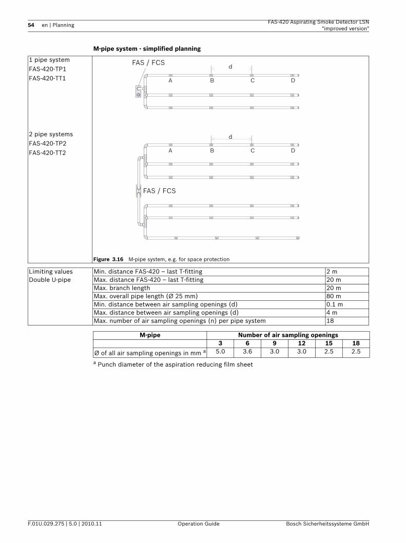
54 en | Planning FAS-420 Aspirating Smoke Detector LSN"improved version"
F.01U.029.275 | 5.0 | 2010.11 Operation Guide Bosch Sicherheitssysteme GmbH
M-pipe system - simplified planning
a Punch diameter of the aspiration reducing film sheet
1 pipe systemFAS-420-TP1FAS-420-TT1
2 pipe systems FAS-420-TP2FAS-420-TT2
Figure 3.16 M-pipe system, e.g. for space protection
d
d
A B C D
A B C D
FAS / FCS
FAS / FCS
Limiting values Min. distance FAS-420 – last T-fitting 2 mDouble U-pipe Max. distance FAS-420 – last T-fitting 20 m
Max. branch length 20 mMax. overall pipe length (Ø 25 mm) 80 mMin. distance between air sampling openings (d) 0.1 mMax. distance between air sampling openings (d) 4 mMax. number of air sampling openings (n) per pipe system 18
M-pipe Number of air sampling openings3 6 9 12 15 18
Ø of all air sampling openings in mm a 5.0 3.6 3.0 3.0 2.5 2.5
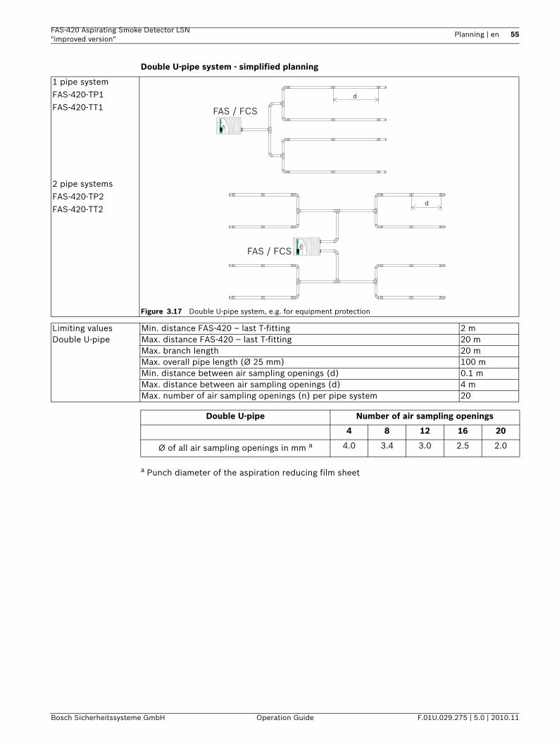
FAS-420 Aspirating Smoke Detector LSN "improved version"
Planning | en 55
Bosch Sicherheitssysteme GmbH Operation Guide F.01U.029.275 | 5.0 | 2010.11
Double U-pipe system - simplified planning
a Punch diameter of the aspiration reducing film sheet
1 pipe systemFAS-420-TP1FAS-420-TT1
2 pipe systems FAS-420-TP2FAS-420-TT2
Figure 3.17 Double U-pipe system, e.g. for equipment protection
FAS / FCS
FAS / FCS
d
d
TITANUS
PRO
·SENS 2 ®
1 2
i1 2 3 4 5 6 7 8 9 10
i
12
1 2 3 4 5 6 7 8 9 10
1 2 3 4 5 6 7 8 9 10
Limiting values Min. distance FAS-420 – last T-fitting 2 mDouble U-pipe Max. distance FAS-420 – last T-fitting 20 m
Max. branch length 20 mMax. overall pipe length (Ø 25 mm) 100 mMin. distance between air sampling openings (d) 0.1 mMax. distance between air sampling openings (d) 4 mMax. number of air sampling openings (n) per pipe system 20
Double U-pipe Number of air sampling openings
4 8 12 16 20
Ø of all air sampling openings in mm a 4.0 3.4 3.0 2.5 2.0
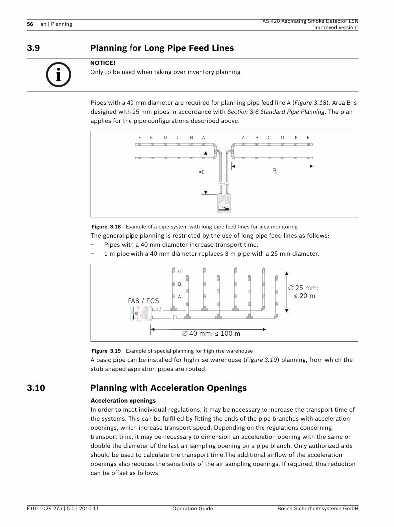
56 en | Planning FAS-420 Aspirating Smoke Detector LSN"improved version"
F.01U.029.275 | 5.0 | 2010.11 Operation Guide Bosch Sicherheitssysteme GmbH
3.9 Planning for Long Pipe Feed Lines
Pipes with a 40 mm diameter are required for planning pipe feed line A (Figure 3.18). Area B is designed with 25 mm pipes in accordance with Section 3.6 Standard Pipe Planning. The plan applies for the pipe configurations described above.
The general pipe planning is restricted by the use of long pipe feed lines as follows:– Pipes with a 40 mm diameter increase transport time. – 1 m pipe with a 40 mm diameter replaces 3 m pipe with a 25 mm diameter.
A basic pipe can be installed for high-rise warehouse (Figure 3.19) planning, from which the stub-shaped aspiration pipes are routed.
3.10 Planning with Acceleration OpeningsAcceleration openingsIn order to meet individual regulations, it may be necessary to increase the transport time of the systems. This can be fulfilled by fitting the ends of the pipe branches with acceleration openings, which increase transport speed. Depending on the regulations concerning transport time, it may be necessary to dimension an acceleration opening with the same or double the diameter of the last air sampling opening on a pipe branch. Only authorized aids should be used to calculate the transport time.The additional airflow of the acceleration openings also reduces the sensitivity of the air sampling openings. If required, this reduction can be offset as follows:
NOTICE! Only to be used when taking over inventory planning
Figure 3.18 Example of a pipe system with long pipe feed lines for area monitoring
Figure 3.19 Example of special planning for high-rise warehouse
AA BB CC DD EE FF
Ai
12
1
2
34
56
789
1 0
1
2
34
56
789
1 0
B
C
B
A
∅ 40 mm: ≤ 100 m
∅ 25 mm: ≤ 20 m
i
12
1 2 3 4 5 6 7 8 9 10
1 2 3 4 5 6 7 8 9 10
FAS / FCS
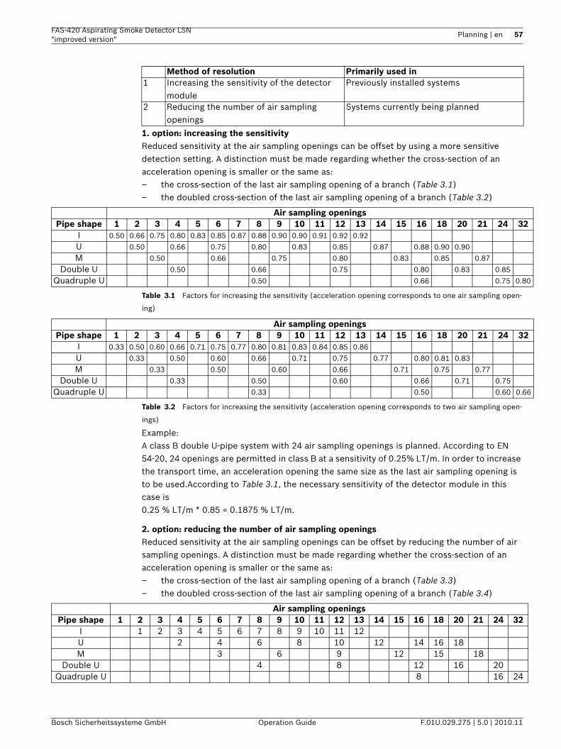
FAS-420 Aspirating Smoke Detector LSN "improved version"
Planning | en 57
Bosch Sicherheitssysteme GmbH Operation Guide F.01U.029.275 | 5.0 | 2010.11
1. option: increasing the sensitivityReduced sensitivity at the air sampling openings can be offset by using a more sensitive detection setting. A distinction must be made regarding whether the cross-section of an acceleration opening is smaller or the same as:– the cross-section of the last air sampling opening of a branch (Table 3.1)– the doubled cross-section of the last air sampling opening of a branch (Table 3.2)
Table 3.1 Factors for increasing the sensitivity (acceleration opening corresponds to one air sampling open-
ing)
Table 3.2 Factors for increasing the sensitivity (acceleration opening corresponds to two air sampling open-
ings)
Example:A class B double U-pipe system with 24 air sampling openings is planned. According to EN 54-20, 24 openings are permitted in class B at a sensitivity of 0.25% LT/m. In order to increase the transport time, an acceleration opening the same size as the last air sampling opening is to be used.According to Table 3.1, the necessary sensitivity of the detector module in this case is 0.25 % LT/m * 0.85 = 0.1875 % LT/m.
2. option: reducing the number of air sampling openingsReduced sensitivity at the air sampling openings can be offset by reducing the number of air sampling openings. A distinction must be made regarding whether the cross-section of an acceleration opening is smaller or the same as:– the cross-section of the last air sampling opening of a branch (Table 3.3)– the doubled cross-section of the last air sampling opening of a branch (Table 3.4)
Method of resolution Primarily used in1 Increasing the sensitivity of the detector
modulePreviously installed systems
2 Reducing the number of air sampling openings
Systems currently being planned
Air sampling openingsPipe shape 1 2 3 4 5 6 7 8 9 10 11 12 13 14 15 16 18 20 21 24 32
I 0.50 0.66 0.75 0.80 0.83 0.85 0.87 0.88 0.90 0.90 0.91 0.92 0.92
U 0.50 0.66 0.75 0.80 0.83 0.85 0.87 0.88 0.90 0.90
M 0.50 0.66 0.75 0.80 0.83 0.85 0.87
Double U 0.50 0.66 0.75 0.80 0.83 0.85
Quadruple U 0.50 0.66 0.75 0.80
Air sampling openingsPipe shape 1 2 3 4 5 6 7 8 9 10 11 12 13 14 15 16 18 20 21 24 32
I 0.33 0.50 0.60 0.66 0.71 0.75 0.77 0.80 0.81 0.83 0.84 0.85 0.86
U 0.33 0.50 0.60 0.66 0.71 0.75 0.77 0.80 0.81 0.83
M 0.33 0.50 0.60 0.66 0.71 0.75 0.77
Double U 0.33 0.50 0.60 0.66 0.71 0.75
Quadruple U 0.33 0.50 0.60 0.66
Air sampling openingsPipe shape 1 2 3 4 5 6 7 8 9 10 11 12 13 14 15 16 18 20 21 24 32
I 1 2 3 4 5 6 7 8 9 10 11 12U 2 4 6 8 10 12 14 16 18M 3 6 9 12 15 18
Double U 4 8 12 16 20Quadruple U 8 16 24
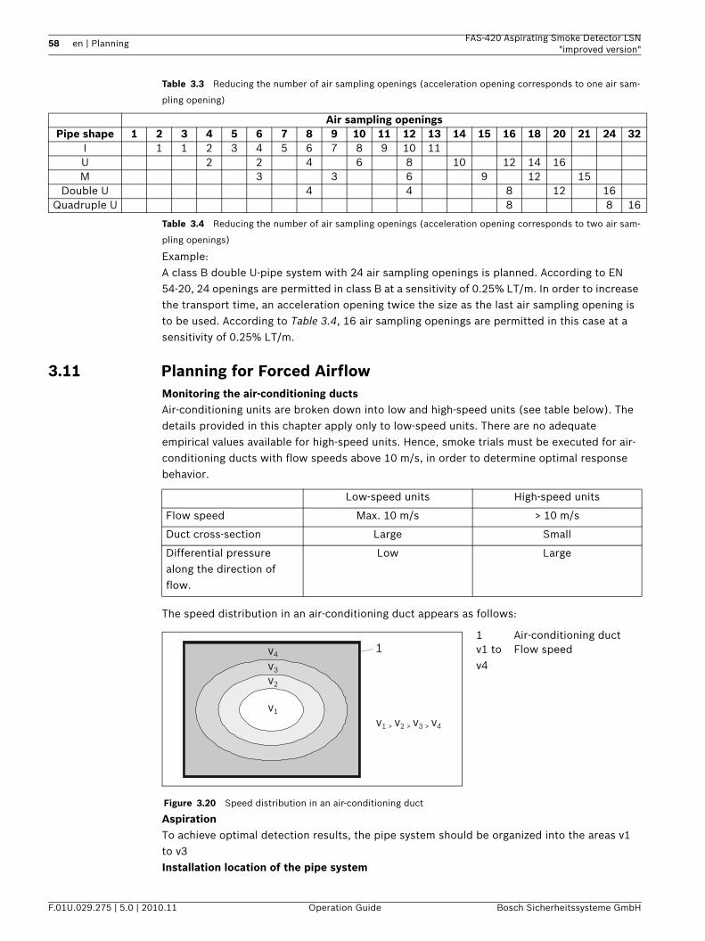
58 en | Planning FAS-420 Aspirating Smoke Detector LSN"improved version"
F.01U.029.275 | 5.0 | 2010.11 Operation Guide Bosch Sicherheitssysteme GmbH
Table 3.3 Reducing the number of air sampling openings (acceleration opening corresponds to one air sam-
pling opening)
Table 3.4 Reducing the number of air sampling openings (acceleration opening corresponds to two air sam-
pling openings)
Example:A class B double U-pipe system with 24 air sampling openings is planned. According to EN 54-20, 24 openings are permitted in class B at a sensitivity of 0.25% LT/m. In order to increase the transport time, an acceleration opening twice the size as the last air sampling opening is to be used. According to Table 3.4, 16 air sampling openings are permitted in this case at a sensitivity of 0.25% LT/m.
3.11 Planning for Forced AirflowMonitoring the air-conditioning ductsAir-conditioning units are broken down into low and high-speed units (see table below). The details provided in this chapter apply only to low-speed units. There are no adequate empirical values available for high-speed units. Hence, smoke trials must be executed for air-conditioning ducts with flow speeds above 10 m/s, in order to determine optimal response behavior.
The speed distribution in an air-conditioning duct appears as follows:
AspirationTo achieve optimal detection results, the pipe system should be organized into the areas v1 to v3 Installation location of the pipe system
Air sampling openingsPipe shape 1 2 3 4 5 6 7 8 9 10 11 12 13 14 15 16 18 20 21 24 32
I 1 1 2 3 4 5 6 7 8 9 10 11U 2 2 4 6 8 10 12 14 16M 3 3 6 9 12 15
Double U 4 4 8 12 16Quadruple U 8 8 16
Low-speed units High-speed units
Flow speed Max. 10 m/s > 10 m/s
Duct cross-section Large Small
Differential pressure along the direction of flow.
Low Large
Figure 3.20 Speed distribution in an air-conditioning duct
1 Air-conditioning ductv1 to v4
Flow speed1
v1
v1 > v2 > v3 > v4
v2
v3
v4
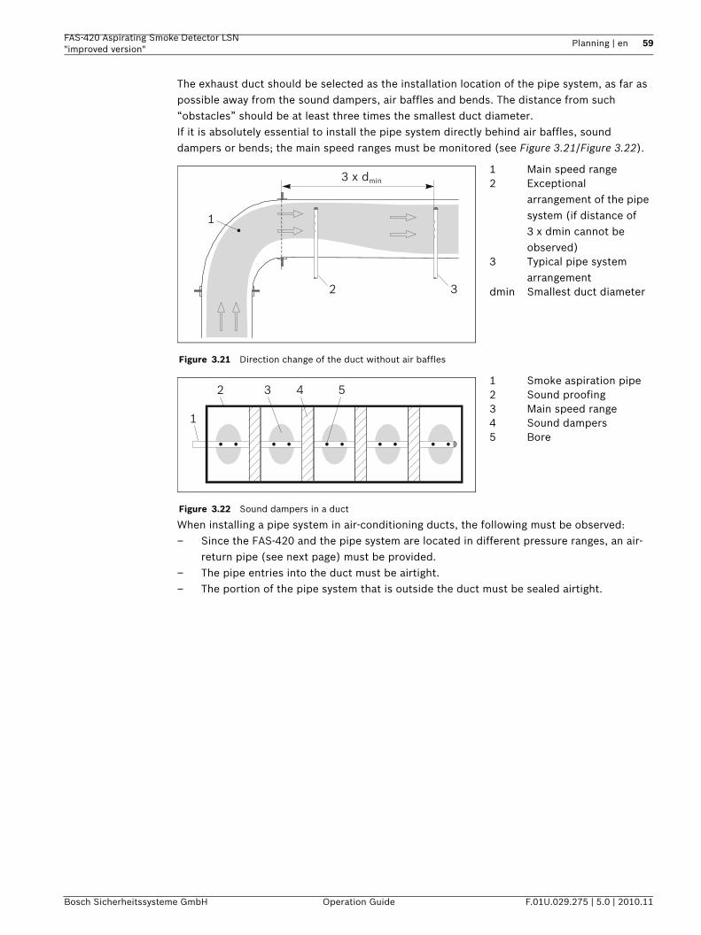
FAS-420 Aspirating Smoke Detector LSN "improved version"
Planning | en 59
Bosch Sicherheitssysteme GmbH Operation Guide F.01U.029.275 | 5.0 | 2010.11
The exhaust duct should be selected as the installation location of the pipe system, as far as possible away from the sound dampers, air baffles and bends. The distance from such “obstacles” should be at least three times the smallest duct diameter. If it is absolutely essential to install the pipe system directly behind air baffles, sound dampers or bends; the main speed ranges must be monitored (see Figure 3.21/Figure 3.22).
When installing a pipe system in air-conditioning ducts, the following must be observed:– Since the FAS-420 and the pipe system are located in different pressure ranges, an air-
return pipe (see next page) must be provided.– The pipe entries into the duct must be airtight.– The portion of the pipe system that is outside the duct must be sealed airtight.
Figure 3.21 Direction change of the duct without air baffles
1 Main speed range2 Exceptional
arrangement of the pipe system (if distance of 3 x dmin cannot be observed)
3 Typical pipe system arrangement
dmin Smallest duct diameter
Figure 3.22 Sound dampers in a duct
1 Smoke aspiration pipe2 Sound proofing3 Main speed range4 Sound dampers5 Bore
3 x dmin
1
2 3
1
4 52 3
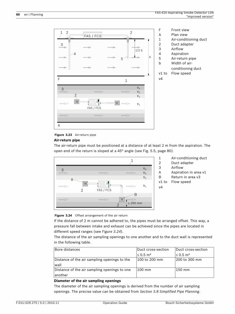
60 en | Planning FAS-420 Aspirating Smoke Detector LSN"improved version"
F.01U.029.275 | 5.0 | 2010.11 Operation Guide Bosch Sicherheitssysteme GmbH
Air-return pipeThe air-return pipe must be positioned at a distance of at least 2 m from the aspiration. The open end of the return is sloped at a 45° angle (see Fig. 5.5, page 80).
If the distance of 2 m cannot be adhered to, the pipes must be arranged offset. This way, a pressure fall between intake and exhaust can be achieved since the pipes are located in different speed ranges (see Figure 3.24).The distance of the air sampling openings to one another and to the duct wall is represented in the following table.
Diameter of the air sampling openingsThe diameter of the air sampling openings is derived from the number of air sampling openings. The precise value can be obtained from Section 3.8 Simplified Pipe Planning.
Figure 3.23 Air-return pipe
F Front viewA Plan view1 Air-conditioning duct2 Duct adapter3 Airflow4 Aspiration5 Air-return pipeb Width of air-
conditioning ductv1 to v4
Flow speed
Figure 3.24 Offset arrangement of the air return
1 Air-conditioning duct2 Duct adapter3 AirflowA Aspiration in area v1B Return in area v3v1 to v4
Flow speed
Bore distances Duct cross-section≤ 0.5 m²
Duct cross-section≤ 0.5 m²
Distance of the air sampling openings to the wall
100 to 200 mm 200 to 300 mm
Distance of the air sampling openings to one another
100 mm 150 mm
1
1
5
2 2
i12345678910
4
3
3
F
v1
v2
v3
v4
A
FAS / FCS
FAS / FCS
5
1/2 b
b
2
1
i12345678910
v1
v2
v3
v4
FAS / FCS2
2 ≥ 200 mm
3
A
B
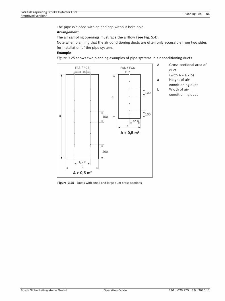
FAS-420 Aspirating Smoke Detector LSN "improved version"
Planning | en 61
Bosch Sicherheitssysteme GmbH Operation Guide F.01U.029.275 | 5.0 | 2010.11
The pipe is closed with an end cap without bore hole.ArrangementThe air sampling openings must face the airflow (see Fig. 5.4).Note when planning that the air-conditioning ducts are often only accessible from two sides for installation of the pipe system.ExampleFigure 3.25 shows two planning examples of pipe systems in air-conditioning ducts.
Figure 3.25 Ducts with small and large duct cross-sections
A Cross-sectional area of duct (with A = a x b)
a Height of air-conditioning duct
b Width of air-conditioning duct
FAS / FCSFAS / FCS
A > 0,5 m2
a100
100
200
150
b
1/2 b
b1/2 b
a
A ≤ 0,5 m2
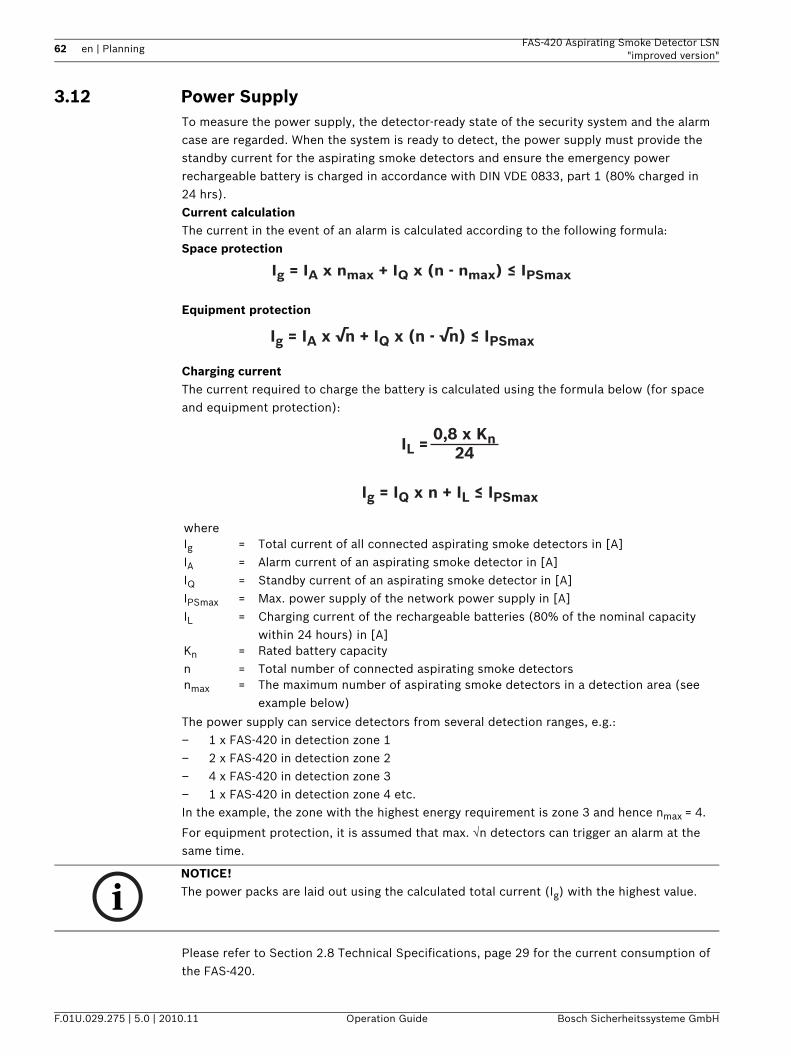
62 en | Planning FAS-420 Aspirating Smoke Detector LSN"improved version"
F.01U.029.275 | 5.0 | 2010.11 Operation Guide Bosch Sicherheitssysteme GmbH
3.12 Power SupplyTo measure the power supply, the detector-ready state of the security system and the alarm case are regarded. When the system is ready to detect, the power supply must provide the standby current for the aspirating smoke detectors and ensure the emergency power rechargeable battery is charged in accordance with DIN VDE 0833, part 1 (80% charged in 24 hrs). Current calculationThe current in the event of an alarm is calculated according to the following formula:Space protection
Equipment protection
Charging currentThe current required to charge the battery is calculated using the formula below (for space and equipment protection):
The power supply can service detectors from several detection ranges, e.g.:– 1 x FAS-420 in detection zone 1– 2 x FAS-420 in detection zone 2– 4 x FAS-420 in detection zone 3– 1 x FAS-420 in detection zone 4 etc.In the example, the zone with the highest energy requirement is zone 3 and hence nmax = 4.
For equipment protection, it is assumed that max. √n detectors can trigger an alarm at the same time.
Please refer to Section 2.8 Technical Specifications, page 29 for the current consumption of the FAS-420.
whereIg = Total current of all connected aspirating smoke detectors in [A]IA = Alarm current of an aspirating smoke detector in [A]IQ = Standby current of an aspirating smoke detector in [A]IPSmax = Max. power supply of the network power supply in [A]IL = Charging current of the rechargeable batteries (80% of the nominal capacity
within 24 hours) in [A]Kn = Rated battery capacityn = Total number of connected aspirating smoke detectorsnmax = The maximum number of aspirating smoke detectors in a detection area (see
example below)
Ig = IA x nmax + IQ x (n - nmax) ≤ IPSmax
Ig = IA x √n + IQ x (n - √n) ≤ IPSmax
IL = 0,8 x Kn
24
Ig = IQ x n + IL ≤ IPSmax
NOTICE! The power packs are laid out using the calculated total current (Ig) with the highest value.
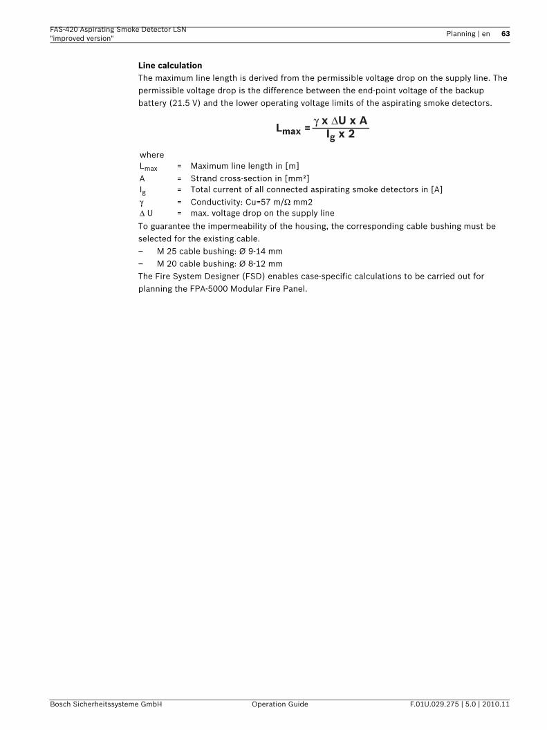
FAS-420 Aspirating Smoke Detector LSN "improved version"
Planning | en 63
Bosch Sicherheitssysteme GmbH Operation Guide F.01U.029.275 | 5.0 | 2010.11
Line calculationThe maximum line length is derived from the permissible voltage drop on the supply line. The permissible voltage drop is the difference between the end-point voltage of the backup battery (21.5 V) and the lower operating voltage limits of the aspirating smoke detectors.
To guarantee the impermeability of the housing, the corresponding cable bushing must be selected for the existing cable.– M 25 cable bushing: Ø 9-14 mm– M 20 cable bushing: Ø 8-12 mmThe Fire System Designer (FSD) enables case-specific calculations to be carried out for planning the FPA-5000 Modular Fire Panel.
whereLmax = Maximum line length in [m]A = Strand cross-section in [mm²]Ig = Total current of all connected aspirating smoke detectors in [A]γ = Conductivity: Cu=57 m/Ω mm2Δ U = max. voltage drop on the supply line
Lmax = γ x ΔU x A
Ig x 2
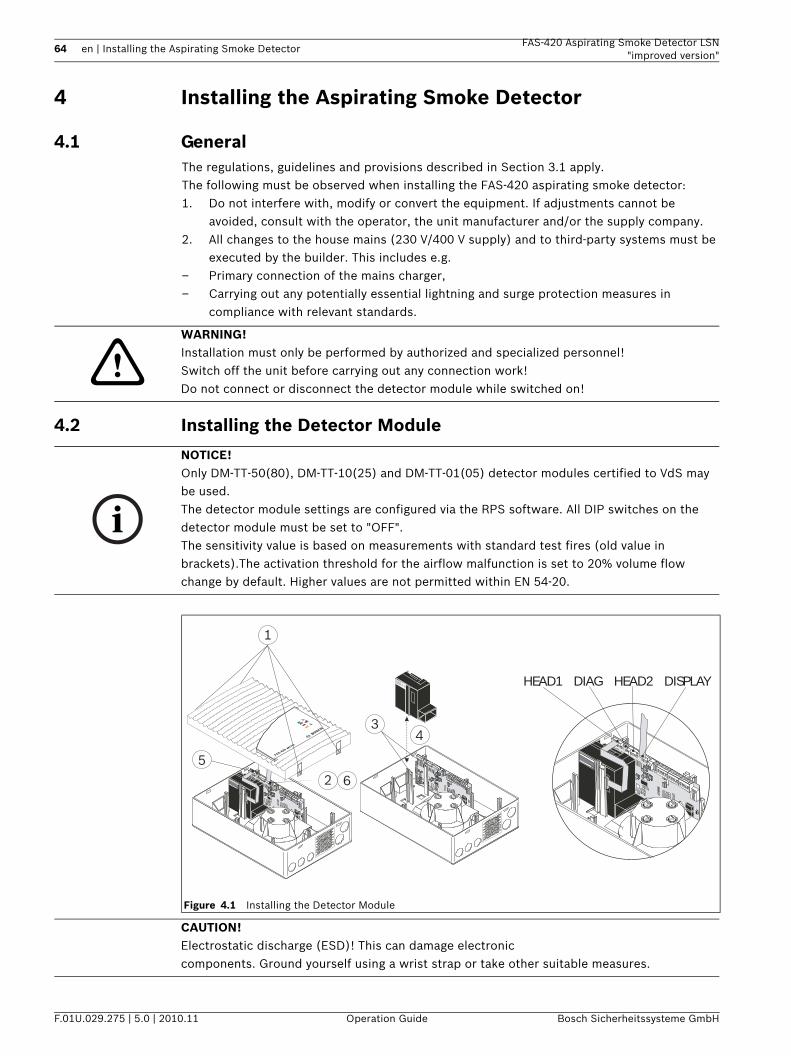
64 en | Installing the Aspirating Smoke Detector FAS-420 Aspirating Smoke Detector LSN"improved version"
F.01U.029.275 | 5.0 | 2010.11 Operation Guide Bosch Sicherheitssysteme GmbH
4 Installing the Aspirating Smoke Detector
4.1 GeneralThe regulations, guidelines and provisions described in Section 3.1 apply.The following must be observed when installing the FAS-420 aspirating smoke detector:1. Do not interfere with, modify or convert the equipment. If adjustments cannot be
avoided, consult with the operator, the unit manufacturer and/or the supply company.2. All changes to the house mains (230 V/400 V supply) and to third-party systems must be
executed by the builder. This includes e.g.– Primary connection of the mains charger,– Carrying out any potentially essential lightning and surge protection measures in
compliance with relevant standards.
4.2 Installing the Detector Module
WARNING! Installation must only be performed by authorized and specialized personnel!Switch off the unit before carrying out any connection work!Do not connect or disconnect the detector module while switched on!
NOTICE! Only DM-TT-50(80), DM-TT-10(25) and DM-TT-01(05) detector modules certified to VdS may be used.The detector module settings are configured via the RPS software. All DIP switches on the detector module must be set to "OFF".The sensitivity value is based on measurements with standard test fires (old value in brackets).The activation threshold for the airflow malfunction is set to 20% volume flow change by default. Higher values are not permitted within EN 54-20.
Figure 4.1 Installing the Detector Module
1
25
6
34
FAS-420 serie
s
HEAD1 DIAG HEAD2 DISPLAY
CAUTION! Electrostatic discharge (ESD)! This can damage electroniccomponents. Ground yourself using a wrist strap or take other suitable measures.
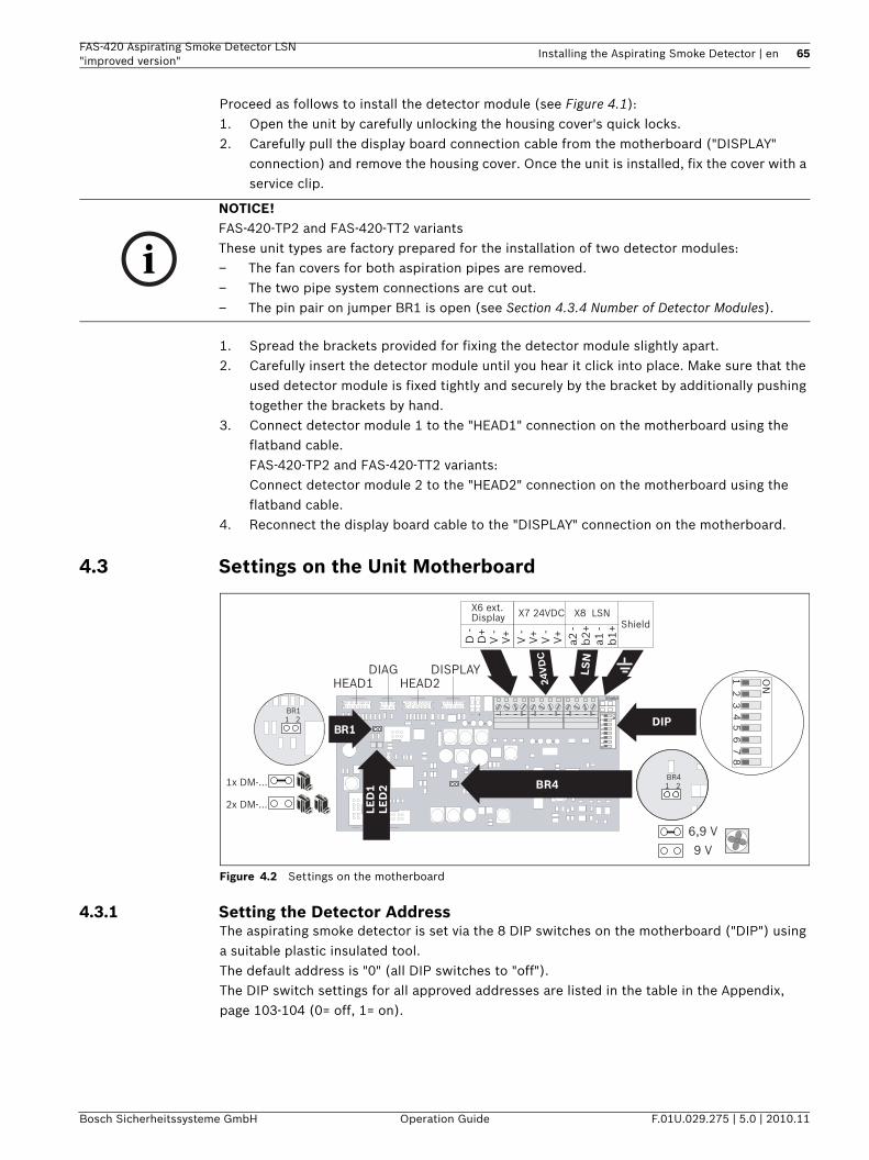
FAS-420 Aspirating Smoke Detector LSN "improved version"
Installing the Aspirating Smoke Detector | en 65
Bosch Sicherheitssysteme GmbH Operation Guide F.01U.029.275 | 5.0 | 2010.11
Proceed as follows to install the detector module (see Figure 4.1):1. Open the unit by carefully unlocking the housing cover's quick locks.2. Carefully pull the display board connection cable from the motherboard ("DISPLAY"
connection) and remove the housing cover. Once the unit is installed, fix the cover with a service clip.
1. Spread the brackets provided for fixing the detector module slightly apart.2. Carefully insert the detector module until you hear it click into place. Make sure that the
used detector module is fixed tightly and securely by the bracket by additionally pushing together the brackets by hand.
3. Connect detector module 1 to the "HEAD1" connection on the motherboard using the flatband cable.FAS-420-TP2 and FAS-420-TT2 variants:Connect detector module 2 to the "HEAD2" connection on the motherboard using the flatband cable.
4. Reconnect the display board cable to the "DISPLAY" connection on the motherboard.
4.3 Settings on the Unit Motherboard
Figure 4.2 Settings on the motherboard
4.3.1 Setting the Detector AddressThe aspirating smoke detector is set via the 8 DIP switches on the motherboard ("DIP") using a suitable plastic insulated tool.The default address is "0" (all DIP switches to "off").The DIP switch settings for all approved addresses are listed in the table in the Appendix, page 103-104 (0= off, 1= on).
NOTICE! FAS-420-TP2 and FAS-420-TT2 variantsThese unit types are factory prepared for the installation of two detector modules:– The fan covers for both aspiration pipes are removed.– The two pipe system connections are cut out.– The pin pair on jumper BR1 is open (see Section 4.3.4 Number of Detector Modules).
BRDIP
24V
DC
1
LSN
BR4BR41 2
BR11 2
HEAD1
a2 -
b2
+a1
-b
1+
HEAD2DISPLAY
6,9 V
9 V
DIAG
1x DM-...
2x DM-...
ON
1 2
3
5 6
78
4ON
1 2
3
5 6
78
4
V -
V+
V -
V+
D -
D+
V -
V+
- +
Shield
X7 24VDCX6 ext. Display X8 LSN
Shield
LED
1LE
D2
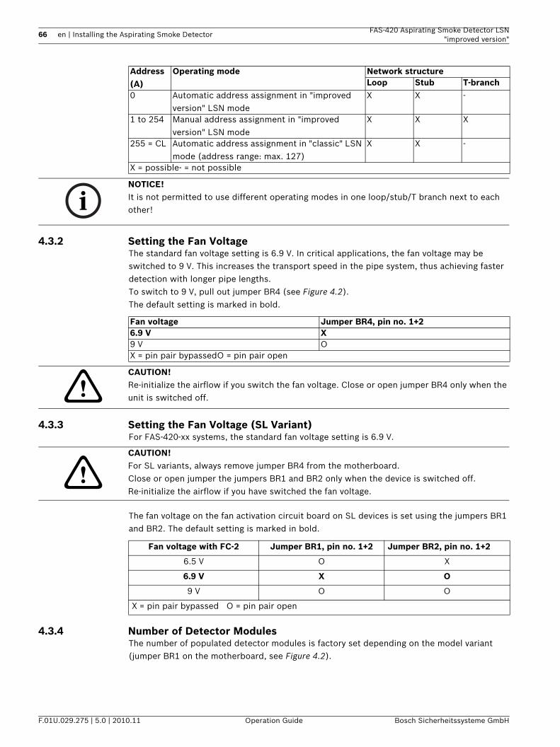
66 en | Installing the Aspirating Smoke Detector FAS-420 Aspirating Smoke Detector LSN"improved version"
F.01U.029.275 | 5.0 | 2010.11 Operation Guide Bosch Sicherheitssysteme GmbH
4.3.2 Setting the Fan VoltageThe standard fan voltage setting is 6.9 V. In critical applications, the fan voltage may be switched to 9 V. This increases the transport speed in the pipe system, thus achieving faster detection with longer pipe lengths.To switch to 9 V, pull out jumper BR4 (see Figure 4.2).The default setting is marked in bold.
4.3.3 Setting the Fan Voltage (SL Variant)For FAS-420-xx systems, the standard fan voltage setting is 6.9 V.
The fan voltage on the fan activation circuit board on SL devices is set using the jumpers BR1 and BR2. The default setting is marked in bold.
4.3.4 Number of Detector ModulesThe number of populated detector modules is factory set depending on the model variant (jumper BR1 on the motherboard, see Figure 4.2).
Address(A)
Operating mode Network structureLoop Stub T-branch
0 Automatic address assignment in "improved version" LSN mode
X X -
1 to 254 Manual address assignment in "improved version" LSN mode
X X X
255 = CL Automatic address assignment in "classic" LSN mode (address range: max. 127)
X X -
X = possible- = not possible
NOTICE! It is not permitted to use different operating modes in one loop/stub/T branch next to each other!
Fan voltage Jumper BR4, pin no. 1+26.9 V X9 V OX = pin pair bypassedO = pin pair open
CAUTION! Re-initialize the airflow if you switch the fan voltage. Close or open jumper BR4 only when the unit is switched off.
CAUTION! For SL variants, always remove jumper BR4 from the motherboard.Close or open jumper the jumpers BR1 and BR2 only when the device is switched off. Re-initialize the airflow if you have switched the fan voltage.
Fan voltage with FC-2 Jumper BR1, pin no. 1+2 Jumper BR2, pin no. 1+2
6.5 V O X
6.9 V X O
9 V O O
X = pin pair bypassed O = pin pair open
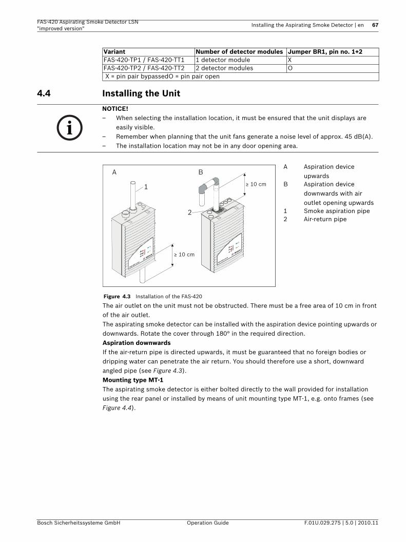
FAS-420 Aspirating Smoke Detector LSN "improved version"
Installing the Aspirating Smoke Detector | en 67
Bosch Sicherheitssysteme GmbH Operation Guide F.01U.029.275 | 5.0 | 2010.11
4.4 Installing the Unit
The air outlet on the unit must not be obstructed. There must be a free area of 10 cm in front of the air outlet.The aspirating smoke detector can be installed with the aspiration device pointing upwards or downwards. Rotate the cover through 180° in the required direction. Aspiration downwardsIf the air-return pipe is directed upwards, it must be guaranteed that no foreign bodies or dripping water can penetrate the air return. You should therefore use a short, downward angled pipe (see Figure 4.3).Mounting type MT-1The aspirating smoke detector is either bolted directly to the wall provided for installation using the rear panel or installed by means of unit mounting type MT-1, e.g. onto frames (see Figure 4.4).
Variant Number of detector modules Jumper BR1, pin no. 1+2FAS-420-TP1 / FAS-420-TT1 1 detector module XFAS-420-TP2 / FAS-420-TT2 2 detector modules O X = pin pair bypassedO = pin pair open
NOTICE! – When selecting the installation location, it must be ensured that the unit displays are
easily visible.– Remember when planning that the unit fans generate a noise level of approx. 45 dB(A). – The installation location may not be in any door opening area.
Figure 4.3 Installation of the FAS-420
A Aspiration device upwards
B Aspiration device downwards with air outlet opening upwards
1 Smoke aspiration pipe2 Air-return pipe
≥ 10 cm
≥ 10 cm
A
1
2
B
FAS-420 series FAS-420 se
ries
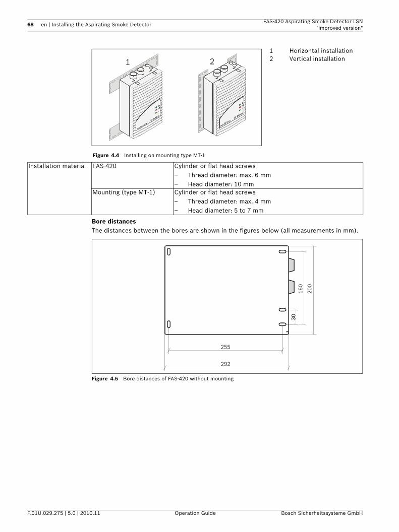
68 en | Installing the Aspirating Smoke Detector FAS-420 Aspirating Smoke Detector LSN"improved version"
F.01U.029.275 | 5.0 | 2010.11 Operation Guide Bosch Sicherheitssysteme GmbH
Bore distancesThe distances between the bores are shown in the figures below (all measurements in mm).
Figure 4.5 Bore distances of FAS-420 without mounting
Figure 4.4 Installing on mounting type MT-1
1 Horizontal installation2 Vertical installation1 2
FAS-420 series
FAS-420 series
Installation material FAS-420 Cylinder or flat head screws– Thread diameter: max. 6 mm– Head diameter: 10 mm
Mounting (type MT-1) Cylinder or flat head screws– Thread diameter: max. 4 mm– Head diameter: 5 to 7 mm
30
255
160
200
292
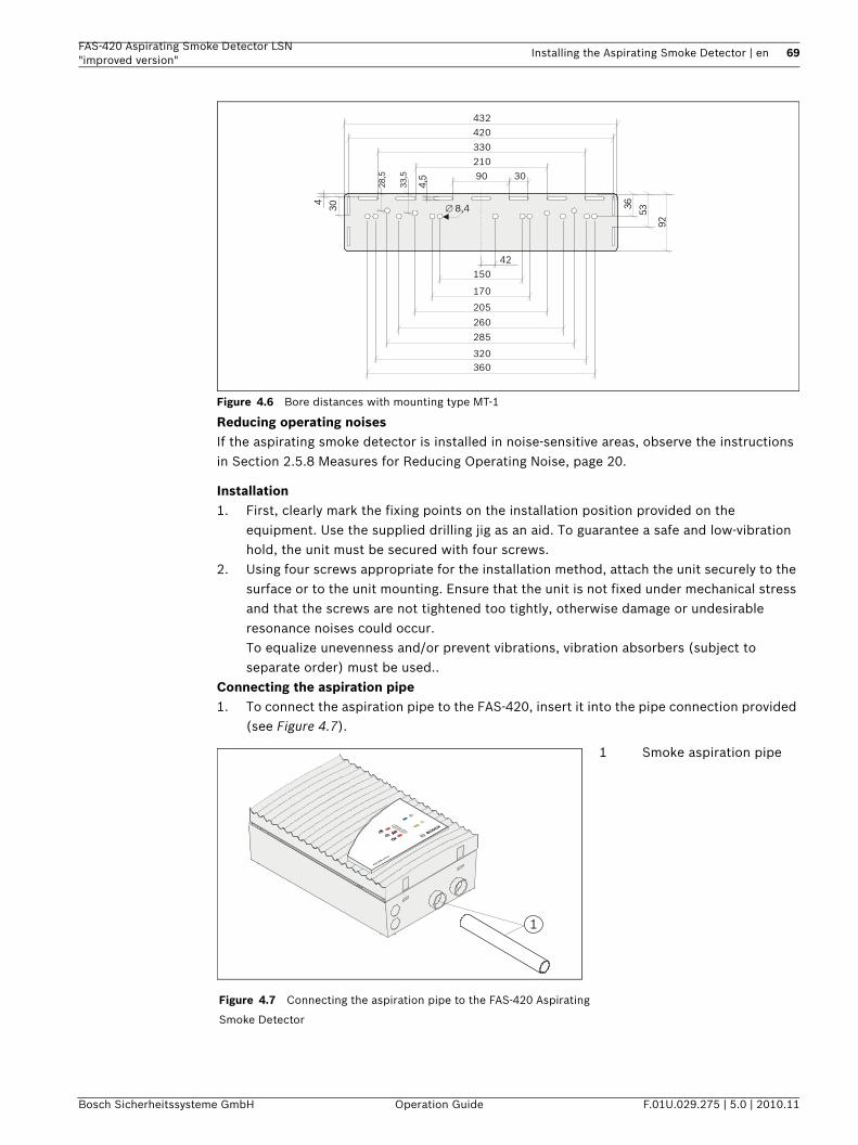
FAS-420 Aspirating Smoke Detector LSN "improved version"
Installing the Aspirating Smoke Detector | en 69
Bosch Sicherheitssysteme GmbH Operation Guide F.01U.029.275 | 5.0 | 2010.11
Figure 4.6 Bore distances with mounting type MT-1
Reducing operating noisesIf the aspirating smoke detector is installed in noise-sensitive areas, observe the instructions in Section 2.5.8 Measures for Reducing Operating Noise, page 20.
Installation1. First, clearly mark the fixing points on the installation position provided on the
equipment. Use the supplied drilling jig as an aid. To guarantee a safe and low-vibration hold, the unit must be secured with four screws.
2. Using four screws appropriate for the installation method, attach the unit securely to the surface or to the unit mounting. Ensure that the unit is not fixed under mechanical stress and that the screws are not tightened too tightly, otherwise damage or undesirable resonance noises could occur.To equalize unevenness and/or prevent vibrations, vibration absorbers (subject to separate order) must be used..
Connecting the aspiration pipe1. To connect the aspiration pipe to the FAS-420, insert it into the pipe connection provided
(see Figure 4.7).
Figure 4.7 Connecting the aspiration pipe to the FAS-420 Aspirating
Smoke Detector
1 Smoke aspiration pipe
90 30
36
53
92
4,5
30
28,5
33,5
4
360320
210
260
285
205
42
8,4∅
330
420
432
170
150
1
FAS-420 serie
s
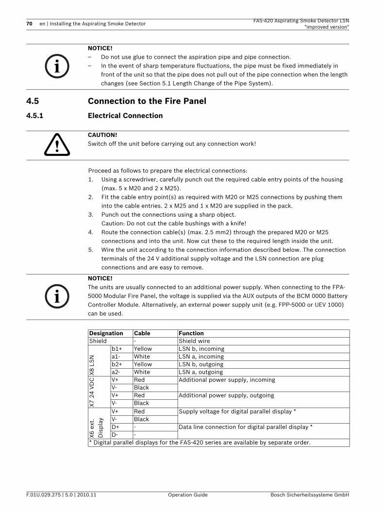
70 en | Installing the Aspirating Smoke Detector FAS-420 Aspirating Smoke Detector LSN"improved version"
F.01U.029.275 | 5.0 | 2010.11 Operation Guide Bosch Sicherheitssysteme GmbH
4.5 Connection to the Fire Panel
4.5.1 Electrical Connection
Proceed as follows to prepare the electrical connections:1. Using a screwdriver, carefully punch out the required cable entry points of the housing
(max. 5 x M20 and 2 x M25).2. Fit the cable entry point(s) as required with M20 or M25 connections by pushing them
into the cable entries. 2 x M25 and 1 x M20 are supplied in the pack.3. Punch out the connections using a sharp object.
Caution: Do not cut the cable bushings with a knife!4. Route the connection cable(s) (max. 2.5 mm2) through the prepared M20 or M25
connections and into the unit. Now cut these to the required length inside the unit.5. Wire the unit according to the connection information described below. The connection
terminals of the 24 V additional supply voltage and the LSN connection are plug connections and are easy to remove.
NOTICE! – Do not use glue to connect the aspiration pipe and pipe connection.– In the event of sharp temperature fluctuations, the pipe must be fixed immediately in
front of the unit so that the pipe does not pull out of the pipe connection when the length changes (see Section 5.1 Length Change of the Pipe System).
CAUTION! Switch off the unit before carrying out any connection work!
NOTICE! The units are usually connected to an additional power supply. When connecting to the FPA-5000 Modular Fire Panel, the voltage is supplied via the AUX outputs of the BCM 0000 Battery Controller Module. Alternatively, an external power supply unit (e.g. FPP-5000 or UEV 1000) can be used.
Designation Cable FunctionShield - Shield wire
X8
LSN
b1+ Yellow LSN b, incominga1- White LSN a, incomingb2+ Yellow LSN b, outgoinga2- White LSN a, outgoing
X7
24VD
C V+ Red Additional power supply, incomingV- BlackV+ Red Additional power supply, outgoingV- Black
X6
ext.
D
isp
lay
V+ Red Supply voltage for digital parallel display *V- BlackD+ - Data line connection for digital parallel display *D- -
* Digital parallel displays for the FAS-420 series are available by separate order.
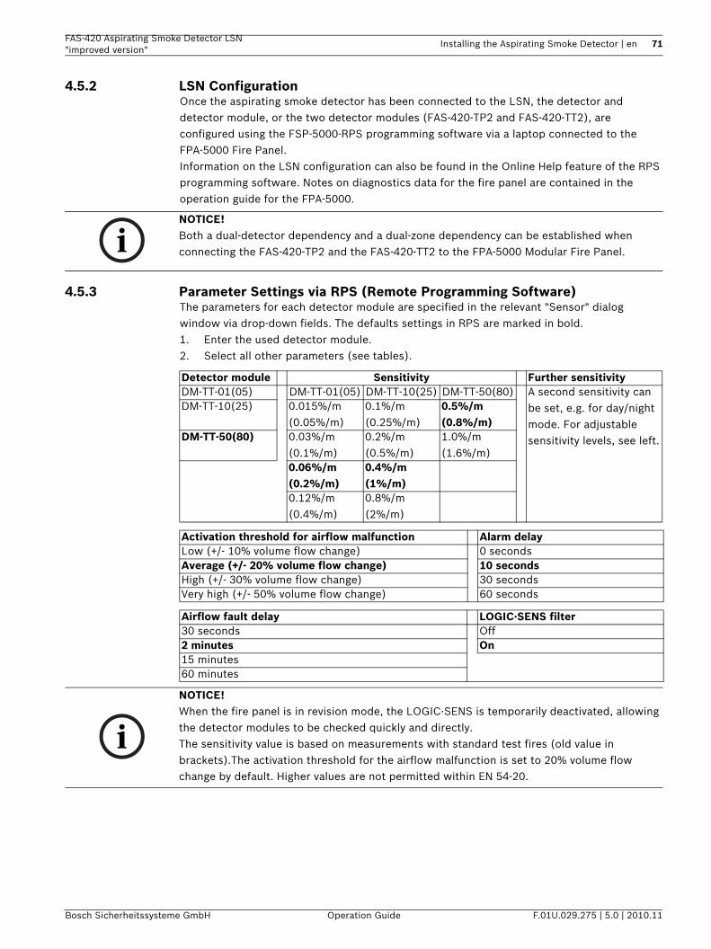
FAS-420 Aspirating Smoke Detector LSN "improved version"
Installing the Aspirating Smoke Detector | en 71
Bosch Sicherheitssysteme GmbH Operation Guide F.01U.029.275 | 5.0 | 2010.11
4.5.2 LSN ConfigurationOnce the aspirating smoke detector has been connected to the LSN, the detector and detector module, or the two detector modules (FAS-420-TP2 and FAS-420-TT2), are configured using the FSP-5000-RPS programming software via a laptop connected to the FPA-5000 Fire Panel. Information on the LSN configuration can also be found in the Online Help feature of the RPS programming software. Notes on diagnostics data for the fire panel are contained in the operation guide for the FPA-5000.
4.5.3 Parameter Settings via RPS (Remote Programming Software)The parameters for each detector module are specified in the relevant "Sensor" dialog window via drop-down fields. The defaults settings in RPS are marked in bold.1. Enter the used detector module.2. Select all other parameters (see tables).
NOTICE! Both a dual-detector dependency and a dual-zone dependency can be established when connecting the FAS-420-TP2 and the FAS-420-TT2 to the FPA-5000 Modular Fire Panel.
Detector module Sensitivity Further sensitivityDM-TT-01(05) DM-TT-01(05) DM-TT-10(25) DM-TT-50(80) A second sensitivity can
be set, e.g. for day/night mode. For adjustable sensitivity levels, see left.
DM-TT-10(25) 0.015%/m(0.05%/m)
0.1%/m(0.25%/m)
0.5%/m(0.8%/m)
DM-TT-50(80) 0.03%/m(0.1%/m)
0.2%/m(0.5%/m)
1.0%/m(1.6%/m)
0.06%/m(0.2%/m)
0.4%/m(1%/m)
0.12%/m(0.4%/m)
0.8%/m(2%/m)
Activation threshold for airflow malfunction Alarm delayLow (+/- 10% volume flow change) 0 seconds Average (+/- 20% volume flow change) 10 secondsHigh (+/- 30% volume flow change) 30 secondsVery high (+/- 50% volume flow change) 60 seconds
Airflow fault delay LOGIC·SENS filter30 seconds Off2 minutes On15 minutes 60 minutes
NOTICE! When the fire panel is in revision mode, the LOGIC·SENS is temporarily deactivated, allowing the detector modules to be checked quickly and directly.The sensitivity value is based on measurements with standard test fires (old value in brackets).The activation threshold for the airflow malfunction is set to 20% volume flow change by default. Higher values are not permitted within EN 54-20.
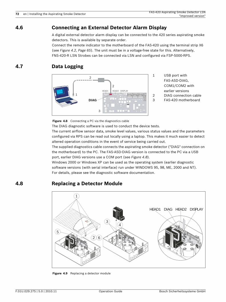
72 en | Installing the Aspirating Smoke Detector FAS-420 Aspirating Smoke Detector LSN"improved version"
F.01U.029.275 | 5.0 | 2010.11 Operation Guide Bosch Sicherheitssysteme GmbH
4.6 Connecting an External Detector Alarm DisplayA digital external detector alarm display can be connected to the 420 series aspirating smoke detectors. This is available by separate order. Connect the remote indicator to the motherboard of the FAS-420 using the terminal strip X6 (see Figure 4.2, Page 65). The unit must be in a voltage-free state for this. Alternatively, FNS-420-R LSN Strobes can be connected via LSN and configured via FSP-5000-RPS.
4.7 Data Logging
The DIAG diagnostic software is used to conduct the device tests.The current airflow sensor data, smoke level values, various status values and the parameters configured via RPS can be read out locally using a laptop. This makes it much easier to detect altered operation conditions in the event of service being carried out.The supplied diagnostics cable connects the aspirating smoke detector ("DIAG" connection on the motherboard) to the PC. The FAS-ASD-DIAG version is connected to the PC via a USB port, earlier DIAG versions use a COM port (see Figure 4.8).Windows 2000 or Windows XP can be used as the operating system (earlier diagnostic software versions (with serial interface) run under WINDOWS 95, 98, ME, 2000 and NT). For details, please see the diagnostic software documentation.
4.8 Replacing a Detector Module
Figure 4.8 Connecting a PC via the diagnostics cable
1 USB port with FAS-ASD-DIAG,COM1/COM2 with earlier versions
2 DIAG connection cable3 FAS-420 motherboard
1
2
2
3
HEAD1 HEAD2 DISPLAY
DIAG
ON
1 2
3
5 6
78
4
- +
Shield
Figure 4.9 Replacing a detector module
1
25
6
34
FAS-420 serie
s
HEAD1 DIAG HEAD2 DISPLAY
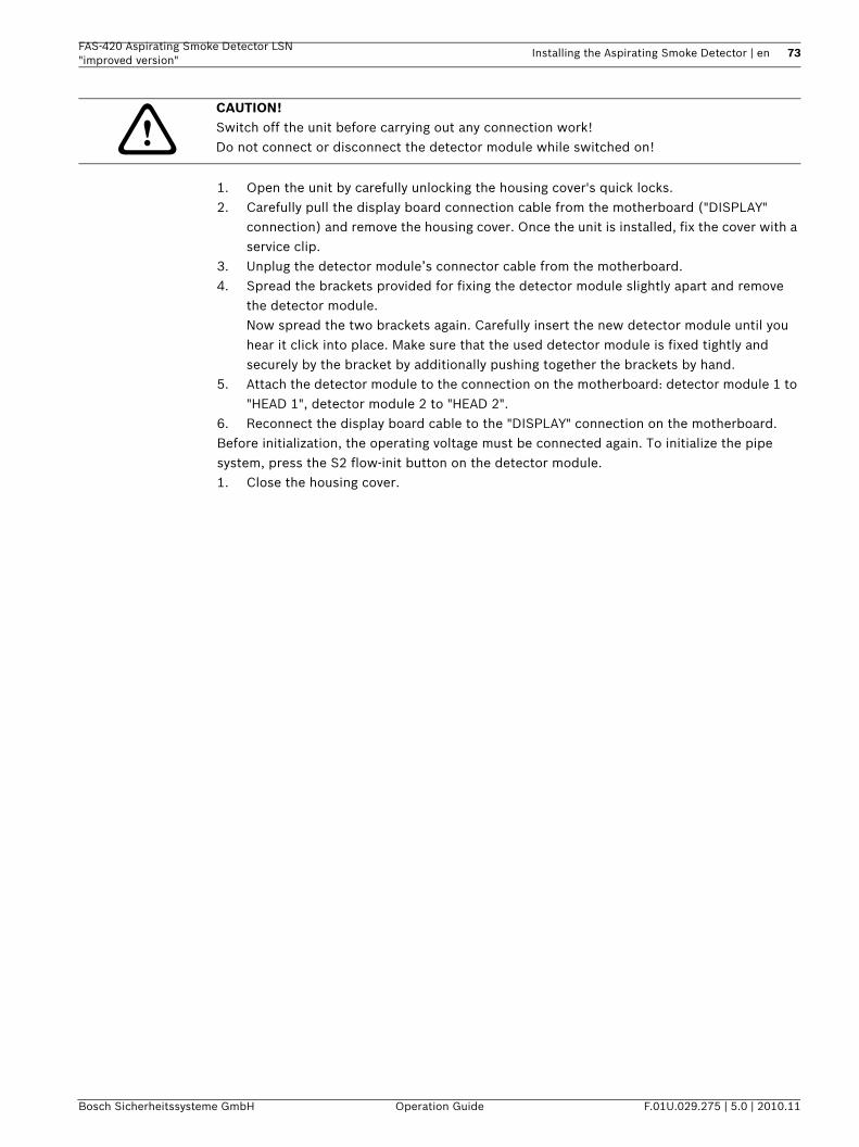
FAS-420 Aspirating Smoke Detector LSN "improved version"
Installing the Aspirating Smoke Detector | en 73
Bosch Sicherheitssysteme GmbH Operation Guide F.01U.029.275 | 5.0 | 2010.11
1. Open the unit by carefully unlocking the housing cover's quick locks.2. Carefully pull the display board connection cable from the motherboard ("DISPLAY"
connection) and remove the housing cover. Once the unit is installed, fix the cover with a service clip.
3. Unplug the detector module’s connector cable from the motherboard.4. Spread the brackets provided for fixing the detector module slightly apart and remove
the detector module.Now spread the two brackets again. Carefully insert the new detector module until you hear it click into place. Make sure that the used detector module is fixed tightly and securely by the bracket by additionally pushing together the brackets by hand.
5. Attach the detector module to the connection on the motherboard: detector module 1 to "HEAD 1", detector module 2 to "HEAD 2".
6. Reconnect the display board cable to the "DISPLAY" connection on the motherboard.Before initialization, the operating voltage must be connected again. To initialize the pipe system, press the S2 flow-init button on the detector module. 1. Close the housing cover.
CAUTION! Switch off the unit before carrying out any connection work!Do not connect or disconnect the detector module while switched on!
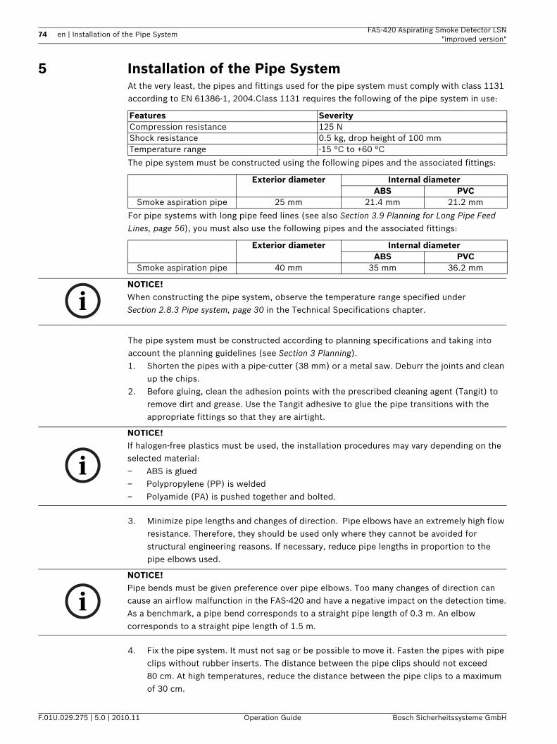
74 en | Installation of the Pipe System FAS-420 Aspirating Smoke Detector LSN"improved version"
F.01U.029.275 | 5.0 | 2010.11 Operation Guide Bosch Sicherheitssysteme GmbH
5 Installation of the Pipe SystemAt the very least, the pipes and fittings used for the pipe system must comply with class 1131 according to EN 61386-1, 2004.Class 1131 requires the following of the pipe system in use:
The pipe system must be constructed using the following pipes and the associated fittings:
For pipe systems with long pipe feed lines (see also Section 3.9 Planning for Long Pipe Feed Lines, page 56), you must also use the following pipes and the associated fittings:
The pipe system must be constructed according to planning specifications and taking into account the planning guidelines (see Section 3 Planning).1. Shorten the pipes with a pipe-cutter (38 mm) or a metal saw. Deburr the joints and clean
up the chips.2. Before gluing, clean the adhesion points with the prescribed cleaning agent (Tangit) to
remove dirt and grease. Use the Tangit adhesive to glue the pipe transitions with the appropriate fittings so that they are airtight.
3. Minimize pipe lengths and changes of direction. Pipe elbows have an extremely high flow resistance. Therefore, they should be used only where they cannot be avoided for structural engineering reasons. If necessary, reduce pipe lengths in proportion to the pipe elbows used.
4. Fix the pipe system. It must not sag or be possible to move it. Fasten the pipes with pipe clips without rubber inserts. The distance between the pipe clips should not exceed 80 cm. At high temperatures, reduce the distance between the pipe clips to a maximum of 30 cm.
Features SeverityCompression resistance 125 NShock resistance 0.5 kg, drop height of 100 mmTemperature range -15 °C to +60 °C
Exterior diameter Internal diameterABS PVC
Smoke aspiration pipe 25 mm 21.4 mm 21.2 mm
Exterior diameter Internal diameterABS PVC
Smoke aspiration pipe 40 mm 35 mm 36.2 mm
NOTICE! When constructing the pipe system, observe the temperature range specified under Section 2.8.3 Pipe system, page 30 in the Technical Specifications chapter.
NOTICE! If halogen-free plastics must be used, the installation procedures may vary depending on the selected material: – ABS is glued– Polypropylene (PP) is welded– Polyamide (PA) is pushed together and bolted.
NOTICE! Pipe bends must be given preference over pipe elbows. Too many changes of direction can cause an airflow malfunction in the FAS-420 and have a negative impact on the detection time.As a benchmark, a pipe bend corresponds to a straight pipe length of 0.3 m. An elbow corresponds to a straight pipe length of 1.5 m.
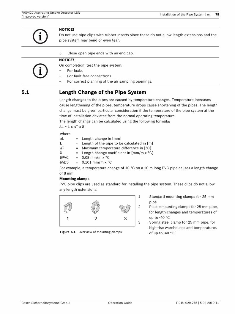
FAS-420 Aspirating Smoke Detector LSN "improved version"
Installation of the Pipe System | en 75
Bosch Sicherheitssysteme GmbH Operation Guide F.01U.029.275 | 5.0 | 2010.11
5. Close open pipe ends with an end cap.
5.1 Length Change of the Pipe SystemLength changes to the pipes are caused by temperature changes. Temperature increases cause lengthening of the pipes, temperature drops cause shortening of the pipes. The length change must be given particular consideration if the temperature of the pipe system at the time of installation deviates from the normal operating temperature.The length change can be calculated using the following formula:ΔL = L x ΔT x δ
For example, a temperature change of 10 °C on a 10 m-long PVC pipe causes a length change of 8 mm.Mounting clampsPVC pipe clips are used as standard for installing the pipe system. These clips do not allow any length extensions.
NOTICE! Do not use pipe clips with rubber inserts since these do not allow length extensions and the pipe system may bend or even tear.
NOTICE! On completion, test the pipe system: – For leaks – For fault-free connections– For correct planning of the air sampling openings.
whereΔL = Length change in [mm]L = Length of the pipe to be calculated in [m]ΔT = Maximum temperature difference in [°C]δ = Length change coefficient in [mm/m x °C]δPVC = 0.08 mm/m x °CδABS = 0.101 mm/m x °C
Figure 5.1 Overview of mounting clamps
1 Standard mounting clamps for 25 mm pipe
2 Plastic mounting clamps for 25 mm pipe, for length changes and temperatures of up to -40 °C
3 Spring steel clamp for 25 mm pipe, for high-rise warehouses and temperatures of up to -40 °C
1 2 3
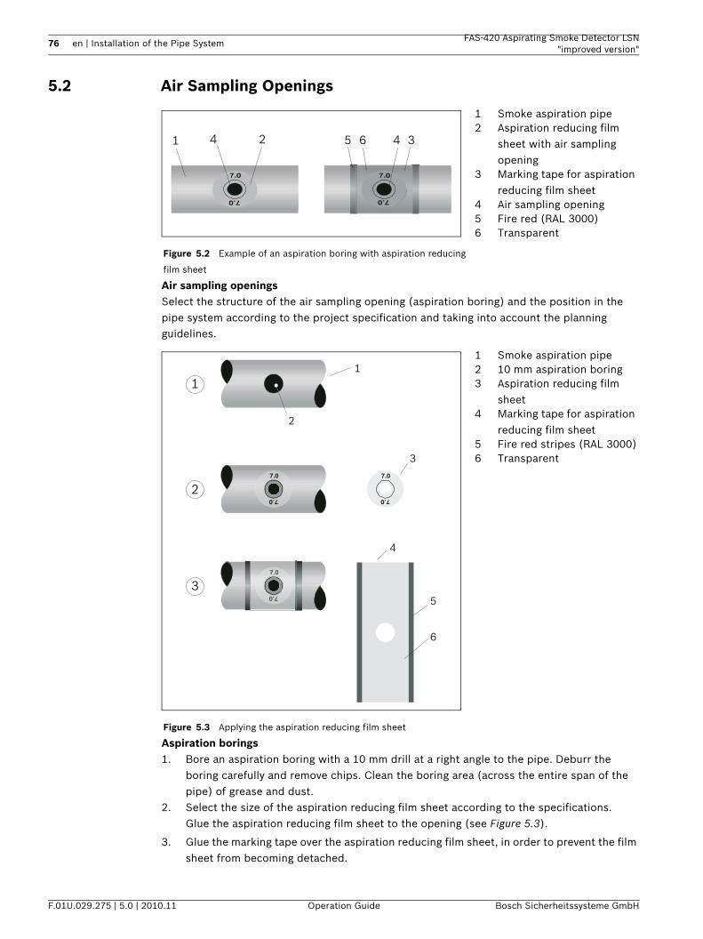
76 en | Installation of the Pipe System FAS-420 Aspirating Smoke Detector LSN"improved version"
F.01U.029.275 | 5.0 | 2010.11 Operation Guide Bosch Sicherheitssysteme GmbH
5.2 Air Sampling Openings
Air sampling openingsSelect the structure of the air sampling opening (aspiration boring) and the position in the pipe system according to the project specification and taking into account the planning guidelines.
Aspiration borings1. Bore an aspiration boring with a 10 mm drill at a right angle to the pipe. Deburr the
boring carefully and remove chips. Clean the boring area (across the entire span of the pipe) of grease and dust.
2. Select the size of the aspiration reducing film sheet according to the specifications.Glue the aspiration reducing film sheet to the opening (see Figure 5.3).
3. Glue the marking tape over the aspiration reducing film sheet, in order to prevent the film sheet from becoming detached.
Figure 5.2 Example of an aspiration boring with aspiration reducing
film sheet
1 Smoke aspiration pipe2 Aspiration reducing film
sheet with air sampling opening
3 Marking tape for aspiration reducing film sheet
4 Air sampling opening5 Fire red (RAL 3000)6 Transparent
Figure 5.3 Applying the aspiration reducing film sheet
1 Smoke aspiration pipe2 10 mm aspiration boring3 Aspiration reducing film
sheet4 Marking tape for aspiration
reducing film sheet5 Fire red stripes (RAL 3000)6 Transparent
1 364 452
7.0
7.0
7.0
7.0
7.0
7.0
1
1
2
3
4
5
6
2
3
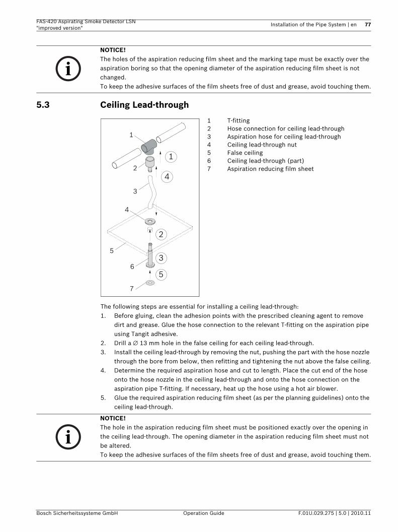
FAS-420 Aspirating Smoke Detector LSN "improved version"
Installation of the Pipe System | en 77
Bosch Sicherheitssysteme GmbH Operation Guide F.01U.029.275 | 5.0 | 2010.11
5.3 Ceiling Lead-through
The following steps are essential for installing a ceiling lead-through:1. Before gluing, clean the adhesion points with the prescribed cleaning agent to remove
dirt and grease. Glue the hose connection to the relevant T-fitting on the aspiration pipe using Tangit adhesive.
2. Drill a ∅ 13 mm hole in the false ceiling for each ceiling lead-through.3. Install the ceiling lead-through by removing the nut, pushing the part with the hose nozzle
through the bore from below, then refitting and tightening the nut above the false ceiling.4. Determine the required aspiration hose and cut to length. Place the cut end of the hose
onto the hose nozzle in the ceiling lead-through and onto the hose connection on the aspiration pipe T-fitting. If necessary, heat up the hose using a hot air blower.
5. Glue the required aspiration reducing film sheet (as per the planning guidelines) onto the ceiling lead-through.
NOTICE! The holes of the aspiration reducing film sheet and the marking tape must be exactly over the aspiration boring so that the opening diameter of the aspiration reducing film sheet is not changed.To keep the adhesive surfaces of the film sheets free of dust and grease, avoid touching them.
1 T-fitting2 Hose connection for ceiling lead-through3 Aspiration hose for ceiling lead-through4 Ceiling lead-through nut5 False ceiling6 Ceiling lead-through (part)7 Aspiration reducing film sheet
1
12
3
5
4
7
4
2
5
36
NOTICE! The hole in the aspiration reducing film sheet must be positioned exactly over the opening in the ceiling lead-through. The opening diameter in the aspiration reducing film sheet must not be altered.To keep the adhesive surfaces of the film sheets free of dust and grease, avoid touching them.
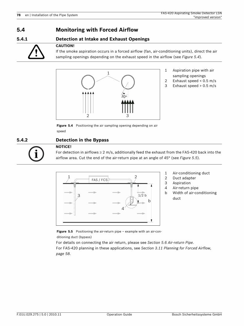
78 en | Installation of the Pipe System FAS-420 Aspirating Smoke Detector LSN"improved version"
F.01U.029.275 | 5.0 | 2010.11 Operation Guide Bosch Sicherheitssysteme GmbH
5.4 Monitoring with Forced Airflow
5.4.1 Detection at Intake and Exhaust Openings
5.4.2 Detection in the Bypass
For details on connecting the air return, please see Section 5.6 Air-return Pipe.For FAS-420 planning in these applications, see Section 3.11 Planning for Forced Airflow, page 58.
CAUTION! If the smoke aspiration occurs in a forced airflow (fan, air-conditioning units), direct the air sampling openings depending on the exhaust speed in the airflow (see Figure 5.4).
Figure 5.4 Positioning the air sampling opening depending on air
speed
1 Aspiration pipe with air sampling openings
2 Exhaust speed < 0.5 m/s3 Exhaust speed > 0.5 m/s
1
2 3
30°
NOTICE! For detection in airflows ≥ 2 m/s, additionally feed the exhaust from the FAS-420 back into the airflow area. Cut the end of the air-return pipe at an angle of 45° (see Figure 5.5).
Figure 5.5 Positioning the air-return pipe – example with an air-con-
ditioning duct (bypass)
1 Air-conditioning duct2 Duct adapter3 Aspiration4 Air-return pipeb Width of air-conditioning
duct
1FAS / FCS
2
3
4
b1/2 b
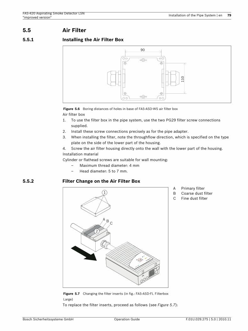
FAS-420 Aspirating Smoke Detector LSN "improved version"
Installation of the Pipe System | en 79
Bosch Sicherheitssysteme GmbH Operation Guide F.01U.029.275 | 5.0 | 2010.11
5.5 Air Filter
5.5.1 Installing the Air Filter Box
Air filter box1. To use the filter box in the pipe system, use the two PG29 filter screw connections
supplied.2. Install these screw connections precisely as for the pipe adapter.3. When installing the filter, note the throughflow direction, which is specified on the type
plate on the side of the lower part of the housing.4. Screw the air filter housing directly onto the wall with the lower part of the housing.Installation materialCylinder or flathead screws are suitable for wall mounting:
– Maximum thread diameter: 4 mm– Head diameter: 5 to 7 mm.
5.5.2 Filter Change on the Air Filter Box
To replace the filter inserts, proceed as follows (see Figure 5.7):
Figure 5.6 Boring distances of holes in base of FAS-ASD-WS air filter box
90
110
Figure 5.7 Changing the filter inserts (in fig.: FAS-ASD-FL Filterbox
Large)
A Primary filterB Coarse dust filterC Fine dust filter
1
2
A BC
FAS-420 serie
s
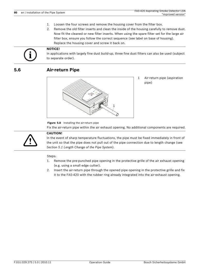
80 en | Installation of the Pipe System FAS-420 Aspirating Smoke Detector LSN"improved version"
F.01U.029.275 | 5.0 | 2010.11 Operation Guide Bosch Sicherheitssysteme GmbH
1. Loosen the four screws and remove the housing cover from the filter box.2. Remove the old filter inserts and clean the inside of the housing carefully to remove dust.
Now fit the cleaned or new filter inserts. When using the spare filter set for the large air filter box, ensure you follow the correct sequence (see label on base of housing).Replace the housing cover and screw it back on.
5.6 Air-return Pipe
Fix the air-return pipe within the air exhaust opening. No additional components are required.
Steps:1. Remove the pre-punched pipe opening in the protective grille of the air exhaust opening
(e.g. using a small edge cutter).2. Insert the air-return pipe through the opened pipe opening in the protective grille and fix
it to the FAS-420 with the rubber ring already integrated into the air-exhaust opening.
NOTICE! In applications with largely fine dust build-up, three fine dust filters can also be used (subject to separate order).
Figure 5.8 Installing the air-return pipe
1 Air-return pipe (aspiration pipe)
1
FAS-420 serie
s
CAUTION! In the event of sharp temperature fluctuations, the pipe must be fixed immediately in front of the unit so that the pipe does not pull out of the pipe connection due to length change (see Section 5.1 Length Change of the Pipe System).
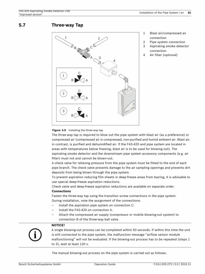
FAS-420 Aspirating Smoke Detector LSN "improved version"
Installation of the Pipe System | en 81
Bosch Sicherheitssysteme GmbH Operation Guide F.01U.029.275 | 5.0 | 2010.11
5.7 Three-way Tap
The three-way tap is required to blow out the pipe system with blast air (as a preference) or compressed air (compressed air is compressed, non-purified and humid ambient air. Blast air, in contrast, is purified and dehumidified air. If the FAS-420 and pipe system are located in areas with temperatures below freezing, blast air is to be used for blowing out). The aspirating smoke detector and the downstream pipe system accessory components (e.g. air filter) must not and cannot be blown-out.A check valve for relieving pressure from the pipe system must be fitted to the end of each pipe branch. The check valve prevents damage to the air sampling openings and prevents dirt deposits from being blown through the pipe system. To prevent aspiration reducing film sheets in deep-freeze areas from tearing, it is advisable to use special deep-freeze aspiration reductions.Check valve and deep-freeze aspiration reductions are available on separate order.ConnectionsFasten the three-way tap using the transition screw connections in the pipe system.During installation, note the assignment of the connections:– Install the aspiration pipe system on connection C.– Install the FAS-420 on connection A.– Attach the compressed air supply (compressor or mobile blowing-out system) to
connection B of the three-way ball valve.
The manual blowing-out process on the pipe system is carried out as follows:
Figure 5.9 Installing the three-way tap
1 Blast air/compressed air connection
2 Pipe system connection3 Aspirating smoke detector
connection4 Air filter (optional)
A
B C
1 2
34
FAS-420 series
AB
C2
AB
C3
AB
C1
NOTICE! A single blowing-out process can be completed within 50 seconds. If within this time the unit is still connected to the pipe system, the malfunction message “airflow sensor module malfunctioning” will not be evaluated. If the blowing-out process has to be repeated (steps 1 to 3), wait at least 120 s.
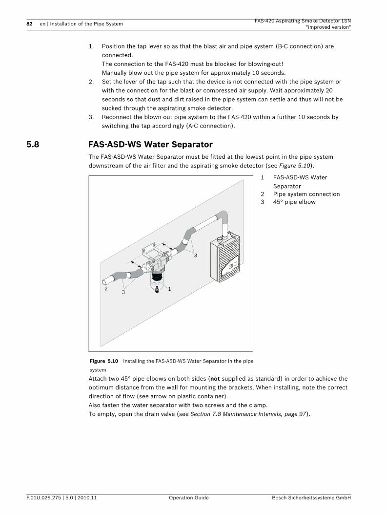
82 en | Installation of the Pipe System FAS-420 Aspirating Smoke Detector LSN"improved version"
F.01U.029.275 | 5.0 | 2010.11 Operation Guide Bosch Sicherheitssysteme GmbH
1. Position the tap lever so as that the blast air and pipe system (B-C connection) are connected.The connection to the FAS-420 must be blocked for blowing-out!Manually blow out the pipe system for approximately 10 seconds.
2. Set the lever of the tap such that the device is not connected with the pipe system or with the connection for the blast or compressed air supply. Wait approximately 20 seconds so that dust and dirt raised in the pipe system can settle and thus will not be sucked through the aspirating smoke detector.
3. Reconnect the blown-out pipe system to the FAS-420 within a further 10 seconds by switching the tap accordingly (A-C connection).
5.8 FAS-ASD-WS Water SeparatorThe FAS-ASD-WS Water Separator must be fitted at the lowest point in the pipe system downstream of the air filter and the aspirating smoke detector (see Figure 5.10).
Attach two 45° pipe elbows on both sides (not supplied as standard) in order to achieve the optimum distance from the wall for mounting the brackets. When installing, note the correct direction of flow (see arrow on plastic container).Also fasten the water separator with two screws and the clamp.To empty, open the drain valve (see Section 7.8 Maintenance Intervals, page 97).
Figure 5.10 Installing the FAS-ASD-WS Water Separator in the pipe
system
1 FAS-ASD-WS Water Separator
2 Pipe system connection3 45° pipe elbow
123
3
FAS-420 serie
s
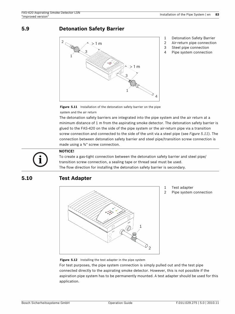
FAS-420 Aspirating Smoke Detector LSN "improved version"
Installation of the Pipe System | en 83
Bosch Sicherheitssysteme GmbH Operation Guide F.01U.029.275 | 5.0 | 2010.11
5.9 Detonation Safety Barrier
The detonation safety barriers are integrated into the pipe system and the air return at a minimum distance of 1 m from the aspirating smoke detector. The detonation safety barrier is glued to the FAS-420 on the side of the pipe system or the air-return pipe via a transition screw connection and connected to the side of the unit via a steel pipe (see Figure 5.11). The connection between detonation safety barrier and steel pipe/transition screw connection is made using a ¾" screw connection.
5.10 Test Adapter
For test purposes, the pipe system connection is simply pulled out and the test pipe connected directly to the aspirating smoke detector. However, this is not possible if the aspiration pipe system has to be permanently mounted. A test adapter should be used for this application.
Figure 5.11 Installation of the detonation safety barrier on the pipe
system and the air return
1 Detonation Safety Barrier2 Air-return pipe connection3 Steel pipe connection4 Pipe system connection
1
1
4
2
3
3
> 1 m
> 1 mFAS-420 se
ries
NOTICE! To create a gas-tight connection between the detonation safety barrier and steel pipe/transition screw connection, a sealing tape or thread seal must be used.The flow direction for installing the detonation safety barrier is secondary.
Figure 5.12 Installing the test adapter in the pipe system
1 Test adapter2 Pipe system connection
1
2
FAS-420 serie
s
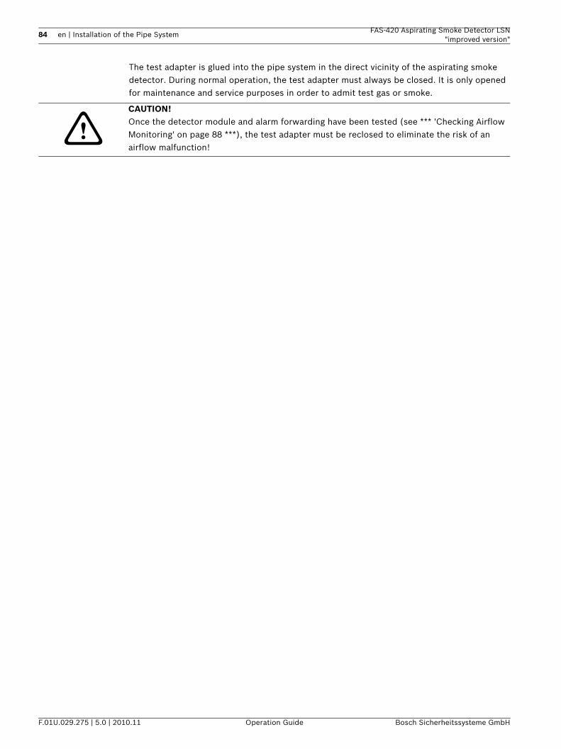
84 en | Installation of the Pipe System FAS-420 Aspirating Smoke Detector LSN"improved version"
F.01U.029.275 | 5.0 | 2010.11 Operation Guide Bosch Sicherheitssysteme GmbH
The test adapter is glued into the pipe system in the direct vicinity of the aspirating smoke detector. During normal operation, the test adapter must always be closed. It is only opened for maintenance and service purposes in order to admit test gas or smoke.
CAUTION! Once the detector module and alarm forwarding have been tested (see *** 'Checking Airflow Monitoring' on page 88 ***), the test adapter must be reclosed to eliminate the risk of an airflow malfunction!
FAS-420 Aspirating Smoke Detector LSN "improved version"
Commissioning | en 85
Bosch Sicherheitssysteme GmbH Operation Guide F.01U.029.275 | 5.0 | 2010.11
6 Commissioning
6.1 PreparationChecking the settingsCheck the settings of the FAS-420 (Section 4.3 Settings on the Unit Motherboard, page 67) prior to commissioning. Then connect the unit to the power supply. The detector module of the FAS-420 is ready for operation after approximately 1 minute.To commission the FAS-420, completely install the pipe system and connect it.Connection testCheck whether… 1. The correct aspiration reducing film sheets are glued to the air sampling openings.2. The pipe system is securely connected to the FAS-420 pipe connection.3. All pipe fittings are glued together and the pipe system is sealed.
To do this, first close all air sampling openings (e.g. with duct tape). Now measure the negative pressure using a digital pressure gauge (see Section 6.6.2 Conducting the Functional Test, page 90)– Either at the opening for the return airflow – Or using a test adapter installed directly upstream of the unit in the aspiration pipe
(see Section 5.10 Test Adapter, page 85).After a short run-up time, the negative pressure must lie within the following range:
– Fan voltage 6.9 V: 250 Pa to 310 Pa– Fan voltage 9 V: 460 Pa to 530 Pa.
FAS-ASD-DIAG Diagnostic SoftwareThen check the system using the DIAG diagnostic software.Follow the procedure below:1. Install the diagnostic software on a laptop or PC (for details on system requirements and
connection, see Section 4.7 Data Logging, page 74).2. The FAS-420 is connected to the PC via the "DIAG" port on the motherboard using the
supplied diagnostics cable.3. The diagnostic software is started.The current FAS-420 data is displayed on the PC's screen.FPA-5000 diagnostics dataNotes on diagnostics data for the fire panel are contained in the user guide for the FPA-5000.
NOTICE! For a later evaluation of the airflow value, record the calibration type (see Section 6.2 Calibrating the Airflow Sensor, page 86), start-up temperature, air pressure and height above sea level in the test log (see Section 8.5 Test Log for Aspirating Smoke Detectors in the FAS-420 Series, page 110).Once the airflow sensor has been calibrated, no further changes may be made to the pipe system.If changes are necessary at a later time, the airflow sensor must be re-calibrated (see Section 6.2 Calibrating the Airflow Sensor).
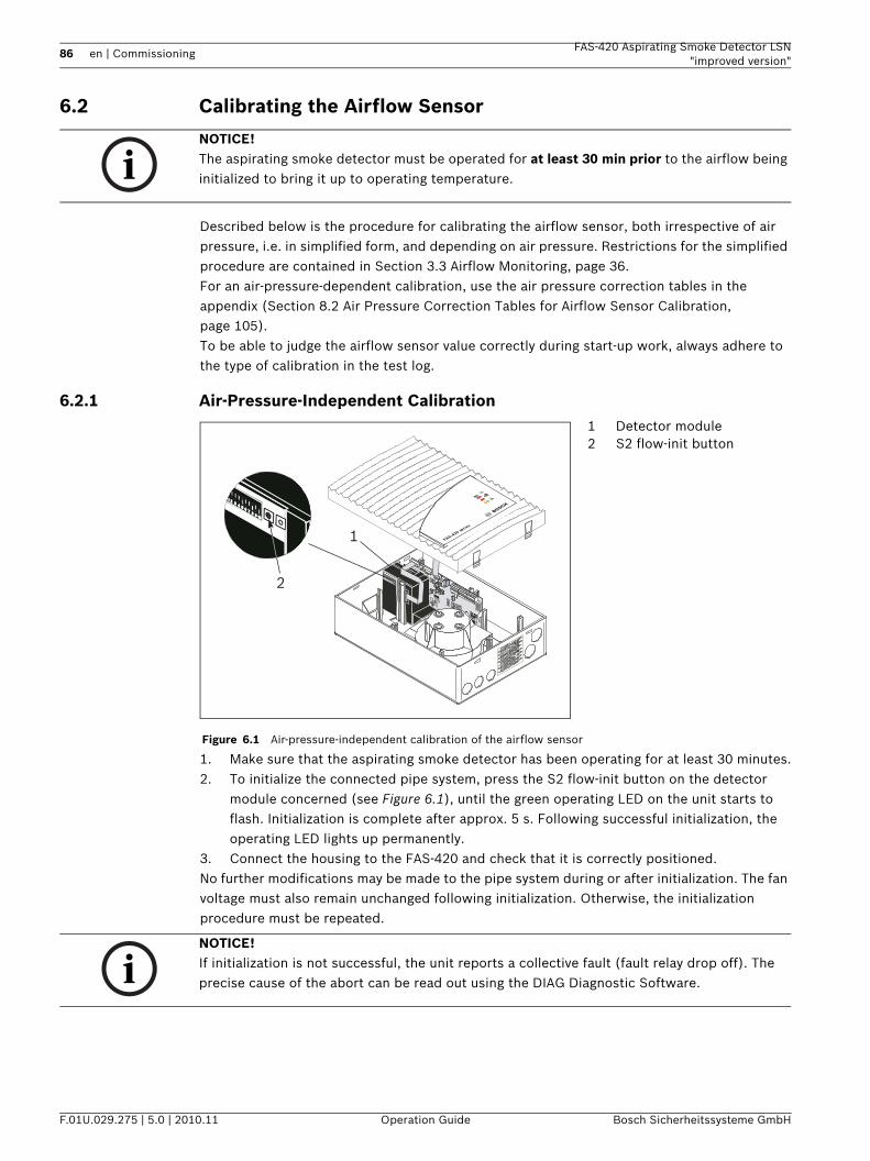
86 en | Commissioning FAS-420 Aspirating Smoke Detector LSN"improved version"
F.01U.029.275 | 5.0 | 2010.11 Operation Guide Bosch Sicherheitssysteme GmbH
6.2 Calibrating the Airflow Sensor
Described below is the procedure for calibrating the airflow sensor, both irrespective of air pressure, i.e. in simplified form, and depending on air pressure. Restrictions for the simplified procedure are contained in Section 3.3 Airflow Monitoring, page 36.For an air-pressure-dependent calibration, use the air pressure correction tables in the appendix (Section 8.2 Air Pressure Correction Tables for Airflow Sensor Calibration, page 105).To be able to judge the airflow sensor value correctly during start-up work, always adhere to the type of calibration in the test log.
6.2.1 Air-Pressure-Independent Calibration
1. Make sure that the aspirating smoke detector has been operating for at least 30 minutes.2. To initialize the connected pipe system, press the S2 flow-init button on the detector
module concerned (see Figure 6.1), until the green operating LED on the unit starts to flash. Initialization is complete after approx. 5 s. Following successful initialization, the operating LED lights up permanently.
3. Connect the housing to the FAS-420 and check that it is correctly positioned.No further modifications may be made to the pipe system during or after initialization. The fan voltage must also remain unchanged following initialization. Otherwise, the initialization procedure must be repeated.
NOTICE! The aspirating smoke detector must be operated for at least 30 min prior to the airflow being initialized to bring it up to operating temperature.
Figure 6.1 Air-pressure-independent calibration of the airflow sensor
1 Detector module2 S2 flow-init button
2
1 FAS-420 serie
s
NOTICE! If initialization is not successful, the unit reports a collective fault (fault relay drop off). The precise cause of the abort can be read out using the DIAG Diagnostic Software.
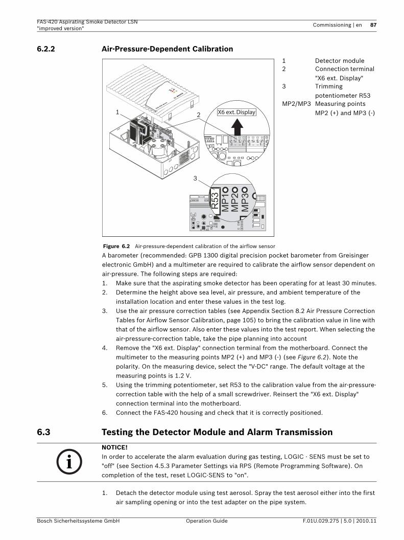
FAS-420 Aspirating Smoke Detector LSN "improved version"
Commissioning | en 87
Bosch Sicherheitssysteme GmbH Operation Guide F.01U.029.275 | 5.0 | 2010.11
6.2.2 Air-Pressure-Dependent Calibration
A barometer (recommended: GPB 1300 digital precision pocket barometer from Greisinger electronic GmbH) and a multimeter are required to calibrate the airflow sensor dependent on air-pressure. The following steps are required:1. Make sure that the aspirating smoke detector has been operating for at least 30 minutes.2. Determine the height above sea level, air pressure, and ambient temperature of the
installation location and enter these values in the test log.3. Use the air pressure correction tables (see Appendix Section 8.2 Air Pressure Correction
Tables for Airflow Sensor Calibration, page 105) to bring the calibration value in line with that of the airflow sensor. Also enter these values into the test report. When selecting the air-pressure-correction table, take the pipe planning into account
4. Remove the "X6 ext. Display" connection terminal from the motherboard. Connect the multimeter to the measuring points MP2 (+) and MP3 (-) (see Figure 6.2). Note the polarity. On the measuring device, select the "V-DC" range. The default voltage at the measuring points is 1.2 V.
5. Using the trimming potentiometer, set R53 to the calibration value from the air-pressure-correction table with the help of a small screwdriver. Reinsert the "X6 ext. Display" connection terminal into the motherboard.
6. Connect the FAS-420 housing and check that it is correctly positioned.
6.3 Testing the Detector Module and Alarm Transmission
1. Detach the detector module using test aerosol. Spray the test aerosol either into the first air sampling opening or into the test adapter on the pipe system.
Figure 6.2 Air-pressure-dependent calibration of the airflow sensor
1 Detector module2 Connection terminal
"X6 ext. Display"3 Trimming
potentiometer R53MP2/MP3 Measuring points
MP2 (+) and MP3 (-)2
3
1FAS-420 se
ries
1 2JU1
R53
MP1
MP2
MP3
MP4
X6 ext. Display
NOTICE! In order to accelerate the alarm evaluation during gas testing, LOGIC · SENS must be set to "off" (see Section 4.5.3 Parameter Settings via RPS (Remote Programming Software). On completion of the test, reset LOGIC·SENS to "on".
88 en | Commissioning FAS-420 Aspirating Smoke Detector LSN"improved version"
F.01U.029.275 | 5.0 | 2010.11 Operation Guide Bosch Sicherheitssysteme GmbH
2. Use the table below to check the transmission line to the fire panel.
6.4 Checking Malfunction Transmission
Malfunction transmission occurs as part of checking the airflow monitoring system (as per section below).Check whether, when a pipe breakage and an obstruction are detected, the malfunction is displayed at the aspirating smoke detector and at the fire panel.
6.5 Checking Airflow MonitoringPipe breakageCheck the breakage detection:1. Detach the pipe from the connection to the FAS-420 or open the test adapter.2. Check whether the malfunction display on the aspirating smoke detector lights up.3. Check the data of the airflow sensor using DIAG Diagnostic Software and a PC or laptop.4. Check whether the malfunction is displayed on the fire panel.5. Enter the results into the test log.ObstructionCheck the obstruction detection:1. Close – depending on the planned airflow monitoring – the corresponding number of air
sampling openings with some duct tape. 2. Check whether the malfunction display on the aspirating smoke detector lights up.3. Check the data of the airflow sensor using DIAG Diagnostic Software and a PC or laptop.4. Check whether the malfunction is displayed on the fire panel.5. Enter the results into the test log.
TroubleshootingIf the airflow malfunctions are not correctly detected by the unit, proceed as follows:Check whether…1. All inlet holes are free2. The pipe system has breaks or fractures
Check… If this is not the case, ...– Whether the alarm is displayed on the
aspirating smoke detector– Check whether the display board is
connected– There is a fault with the aspirating smoke
detector Replace the detector module– Whether the alarm is transmitted to the
fire panel and reported on the appropriate line
– Check the transmission lines
NOTICE! The steps below may only be carried out following an airflow calibration in accordance with Section 6.2 Calibrating the Airflow Sensor.
NOTICE! A pipe breakage or pipe obstruction is indicated by a flash code via an LED on the detector module (see Section 7.2 Flash Code Table, page 94):– Breakage: 3 x flashes– Obstruction: 2 x flashesThe corresponding flash code is repeated every two seconds.
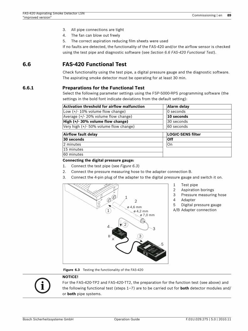
FAS-420 Aspirating Smoke Detector LSN "improved version"
Commissioning | en 89
Bosch Sicherheitssysteme GmbH Operation Guide F.01U.029.275 | 5.0 | 2010.11
3. All pipe connections are tight4. The fan can blow out freely5. The correct aspiration reducing film sheets were usedIf no faults are detected, the functionality of the FAS-420 and/or the airflow sensor is checked using the test pipe and diagnostic software (see Section 6.6 FAS-420 Functional Test).
6.6 FAS-420 Functional TestCheck functionality using the test pipe, a digital pressure gauge and the diagnostic software. The aspirating smoke detector must be operating for at least 30 min.
6.6.1 Preparations for the Functional TestSelect the following parameter settings using the FSP-5000-RPS programming software (the settings in the bold font indicate deviations from the default setting):
Connecting the digital pressure gauge:1. Connect the test pipe (see Figure 6.3)2. Connect the pressure measuring hose to the adapter connection B.3. Connect the 4-pin plug of the adapter to the digital pressure gauge and switch it on.
Activation threshold for airflow malfunction Alarm delayLow (+/- 10% volume flow change) 0 seconds Average (+/- 20% volume flow change) 10 secondsHigh (+/- 30% volume flow change) 30 secondsVery high (+/- 50% volume flow change) 60 seconds
Airflow fault delay LOGIC·SENS filter30 seconds Off2 minutes On15 minutes 60 minutes
Figure 6.3 Testing the functionality of the FAS-420
1 Test pipe2 Aspiration borings3 Pressure measuring hose4 Adapter5 Digital pressure gaugeA/B Adapter connection
BA
ø 7,0 mmø 4,2 mm
ø 4,6 mm
1
3
2
34
5
1
2
FAS-420 serie
s
NOTICE! For the FAS-420-TP2 and FAS-420-TT2, the preparation for the function test (see above) and the following functional test (steps 1–7) are to be carried out for both detector modules and/or both pipe systems.
90 en | Commissioning FAS-420 Aspirating Smoke Detector LSN"improved version"
F.01U.029.275 | 5.0 | 2010.11 Operation Guide Bosch Sicherheitssysteme GmbH
6.6.2 Conducting the Functional TestThe functional test can be conducted with or without a digital pressure gauge. The complete test is described below. If the test on the FAS-420 reveals deviations from the described procedure, the unit or its airflow sensor is defective.1. Make sure that the aspirating smoke detector has been operating for at least 30 minutes.2. Close all the test pipe’s aspiration borings with some duct tape.After a few seconds,
the LED flash code on detector module I and detector module II must signal an obstruction (see NOTE). After a short run-up time, the negative pressure must lie within the following range:– Fan voltage 6.9 V: 250 Pa to 310 Pa– Fan voltage 9 V: 460 Pa to 530 Pa.
3. Open all of the test pipe's aspiration borings. After a few seconds, the flash code of the LED must go out.
4. Remove the test pipe. The LED flash code on detector module I and detector module II must signal a breakage.
5. Reconnect the test pipe to the device. After a few seconds, the flash code of the LED must go out.
DIAG diagnostic softwareThe DIAG Diagnostic Software can be used to track airflow values during the function test. Save all diagnostics data as a file. To be able to compare the data read out, save each file under a different file name.Information for installing the diagnostic software can be found in Section 6.1 Preparation, page 85.
NOTICE! A pipe breakage or pipe obstruction is indicated by a flash code via an LED on the detector module (see Section 7.2 Flash Code Table, page 94):– Breakage: 3 x flashes– Obstruction: 2 x flashesThe corresponding flash code is repeated every two seconds.
NOTICE! – Once any faults have been rectified, the parameter settings must be restored to their
original status via the RPS software.– The commissioning procedure must be repeated from Section 6.2 Calibrating the Airflow
Sensor.– Once commissioning has been concluded, the set values must be collected and saved
using the DIAG Diagnostic Software. A printout of the set values should be placed in the project folder.
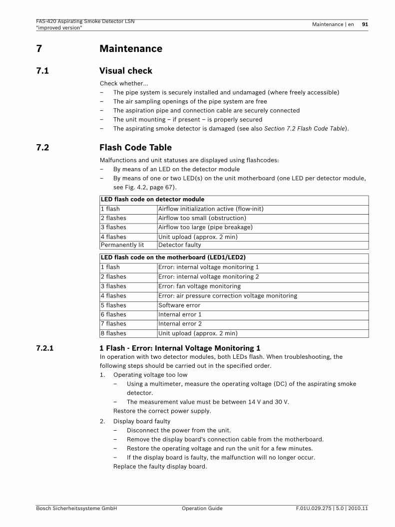
FAS-420 Aspirating Smoke Detector LSN "improved version"
Maintenance | en 91
Bosch Sicherheitssysteme GmbH Operation Guide F.01U.029.275 | 5.0 | 2010.11
7 Maintenance
7.1 Visual checkCheck whether…– The pipe system is securely installed and undamaged (where freely accessible)– The air sampling openings of the pipe system are free– The aspiration pipe and connection cable are securely connected– The unit mounting – if present – is properly secured– The aspirating smoke detector is damaged (see also Section 7.2 Flash Code Table).
7.2 Flash Code TableMalfunctions and unit statuses are displayed using flashcodes:– By means of an LED on the detector module– By means of one or two LED(s) on the unit motherboard (one LED per detector module,
see Fig. 4.2, page 67).
7.2.1 1 Flash - Error: Internal Voltage Monitoring 1In operation with two detector modules, both LEDs flash. When troubleshooting, the following steps should be carried out in the specified order.1. Operating voltage too low
– Using a multimeter, measure the operating voltage (DC) of the aspirating smoke detector.
– The measurement value must be between 14 V and 30 V.Restore the correct power supply.
2. Display board faulty– Disconnect the power from the unit.– Remove the display board's connection cable from the motherboard.– Restore the operating voltage and run the unit for a few minutes.– If the display board is faulty, the malfunction will no longer occur.Replace the faulty display board.
LED flash code on detector module
1 flash Airflow initialization active (flow-init)
2 flashes Airflow too small (obstruction)
3 flashes Airflow too large (pipe breakage)
4 flashes Unit upload (approx. 2 min)Permanently lit Detector faulty
LED flash code on the motherboard (LED1/LED2)
1 flash Error: internal voltage monitoring 1
2 flashes Error: internal voltage monitoring 2
3 flashes Error: fan voltage monitoring
4 flashes Error: air pressure correction voltage monitoring
5 flashes Software error
6 flashes Internal error 1
7 flashes Internal error 2
8 flashes Unit upload (approx. 2 min)
92 en | Maintenance FAS-420 Aspirating Smoke Detector LSN"improved version"
F.01U.029.275 | 5.0 | 2010.11 Operation Guide Bosch Sicherheitssysteme GmbH
3. Motherboard faulty– You will need a second motherboard to make this diagnosis.– Disconnect the power from the unit.– Replace the motherboard with a new motherboard of the same type.– Restore the operating voltage and run the unit for a few minutes.– If the motherboard is faulty, the malfunction will no longer occur.Replace the faulty motherboard.
7.2.2 2 Flashes - Error: Internal Voltage Monitoring 2In operation with two detector modules, both LEDs flash. When troubleshooting, the following steps should be carried out in the specified order.1. Operating voltage too low
– Using a multimeter, measure the operating voltage (DC) of the aspirating smoke detector.
– The measurement value must be between 14 V and 30 V.Restore the correct power supply.
2. Detector module faulty– Disconnect the power from the unit.– Replace the detector module incl. connection cable with a new module of the same
type.– Restore the operating voltage and run the unit for a few minutes.– If the detector module is faulty, the malfunction will no longer occur.– If you are using two detector modules, repeat the process with the second detector
module.Replace the faulty detector module.
3. Motherboard faulty– You will need a second motherboard to make this diagnosis.– Disconnect the power from the unit.– Replace the motherboard with a new motherboard of the same type.– Restore the operating voltage and run the unit for a few minutes.– If the motherboard is faulty, the malfunction will no longer occur.Replace the faulty motherboard.
7.2.3 3 Flashes - Error: Fan Voltage MonitoringIn operation with two detector modules, both LEDs flash. When troubleshooting, the following steps should be carried out in the specified order.1. Operating voltage too low
– Using a multimeter, measure the operating voltage (DC) of the aspirating smoke detector.
– The measurement value must be between 14 V and 30 V.Restore the correct power supply.
2. Fan connection poles reversed– The fan does not move.– Disconnect the power from the unit.– Disconnect the fan connection cable from the motherboard. – Restore the operating voltage and run the unit for a few minutes.– If the fan connection is faulty, the malfunction will no longer occur.Check the fan connection on the motherboard: terminal 1 = red, terminal 2 = black).
FAS-420 Aspirating Smoke Detector LSN "improved version"
Maintenance | en 93
Bosch Sicherheitssysteme GmbH Operation Guide F.01U.029.275 | 5.0 | 2010.11
3. The fans are faulty or obstructed– If the fan connection is correct (troubleshooting step 2), the malfunction will
reoccur.– Measure the fan voltage (DC) using a multimeter.– If the fan voltage is outside the limits specified below, the fan may be faulty:
If the fan voltage is set at 6.9 V, the maximum permissible setting is 7.6 V and the minimum is 6.0 V.
If the fan voltage is set at 9.0 V, the maximum permissible setting is 10.0 V and the minimum is 7.8 V.
Replace the entire housing, as the fans cannot be removed.
4. Motherboard faulty– You will need a second motherboard to make this diagnosis.– Disconnect the power from the unit.– Replace the motherboard with a new motherboard of the same type.– Restore the operating voltage and run the unit for a few minutes.– If the motherboard is faulty, the malfunction will no longer occur.Replace the faulty motherboard.
7.2.4 4 Flashes - Error: Air Pressure Correction Voltage MonitoringIn operation with two detector modules, both LEDs flash. When troubleshooting, the following steps should be carried out in the specified order.1. The R3 potentiometer is moved to the setting for the pressure-dependent airflow
calibration.– Using a multimeter, measure the voltage (DC) at measuring points MP2 (x) and MP3
(-).– The default measurement value is 1.2 V. However, deviations may occur due to the
calibration of the airflow dependent on air pressure.– The measurement value must be between 0.5 V and 1.9 V. If the measured voltage
value is outside of this range, the R3 potentiometer setting is faulty.Note: The malfunction only occurs at voltages below 0.2 V or above 2.3 V.
Using the R3 potentiometer, reset the voltage to a point between the measuring points MP2 (x) and MP3 (-). 1.2 V for calibration independently of air pressure.In accordance with the air pressure correction table for air-pressure-dependent calibration.
2. Motherboard faulty– The voltage cannot be set in step 1.– Disconnect the power from the unit.– Remove the detector module's connection cables from the motherboard.– Restore the operating voltage and run the unit for a few minutes.– If the voltage at measuring points MP2 and MP3 cannot be set with the R3
potentiometer, the motherboard is faulty.Note: If operating without a detector module, the diagnostics LED flashes 7 times.
Replace the faulty motherboard.
94 en | Maintenance FAS-420 Aspirating Smoke Detector LSN"improved version"
F.01U.029.275 | 5.0 | 2010.11 Operation Guide Bosch Sicherheitssysteme GmbH
3. Detector module faulty– Disconnect the power from the unit.– Reconnect the connection cable for the first detector module to the motherboard.– Restore the operating voltage and run the unit for a few minutes.– If the error reoccurs, the first detector module is faulty.– If you are using two detector modules, repeat the process with the second detector
module.Replace the faulty detector module.
7.2.5 5 Flashes - Error: Programming ErrorIn operation with two detector modules, both LEDs flash. The motherboard is faulty and must be replaced with a new board.
7.2.6 6 Flashes or 7 Flashes - Error: Internal Error 1 or Internal Error 2If only one LED flashes in operation with two detector modules, the associated detector module is probably faulty. When troubleshooting, the following steps should be carried out in the specified order.1. Incorrect detector module in use.
– Ensure that you are using a suitable detector module.If a detector module is unsuitable, replace it with a suitable one.
2. Faulty connection cable between motherboard and detector module.– Disconnect the power from the unit.– Replace the connection cable with a new one.– Restore the operating voltage and run the unit for a few minutes.– If the malfunction no longer occurs, the faulty connection cable was responsible for
the error.Replace the faulty connection cable.
3. Detector module faulty– Disconnect the power from the unit.– Replace the detector module with a new one of the same type.– Restore the operating voltage and run the unit for a few minutes.– If the error does not reoccur, the detector module was faulty.Replace the faulty detector module.
4. The motherboard is faulty.– If you are using two detector modules, both diagnostics LEDs flash.– Disconnect the power from the unit.– Replace the motherboard with a new motherboard of the same type.– Restore the operating voltage and run the unit for a few minutes.– If the error does not reoccur, the motherboard was faulty.
7.2.7 8 Flashes: Unit InitializationThis display does not indicate an error. The LEDs flash during the initialization phase, after the power supply has been connected, to indicate that the system is starting. During the initialization phase, the detector is unable to detect smoke.
7.3 Detector Module and Alarm TransmissionProceed in accordance with Section 6.3 Checking the Detector Module and Alarm Transmission, page 89. Also check the detector module visually for exterior contamination or damage and replace if necessary.
FAS-420 Aspirating Smoke Detector LSN "improved version"
Maintenance | en 95
Bosch Sicherheitssysteme GmbH Operation Guide F.01U.029.275 | 5.0 | 2010.11
7.4 Pipe systemCheck the pipe system and the air sampling openings for obstruction in areas susceptible to dust particles or icing. Where necessary, blow out the pipe system and air sampling openings using blast air (class 3 for recycling areas or class 2 for deep-freeze areas). Use a mobile cylinder of compressed air (blowing-out system) or activate the manual blowing-out system located on site. The components (compressors, compressed air containers, dryers) required to supply the compressed air can be obtained directly from the relevant compressed air system suppliers.
Blowing outThe compressed air supply to the pipe system must be connected so that only the pipe system itself is blown out. The aspirating smoke detector and the downstream accessory components of the pipe system (e.g. air filter) must not and cannot be blown out.A check valve must be installed at the end of each pipe branch. The check valve prevents damage to the air sampling openings and prevents dirt deposits from being blown through the pipe system. To prevent aspiration reducing film sheets in deep-freeze areas from tearing, it is advisable to use special deep-freeze aspiration reductions.The compressed air supply and compressed air connection must be installed so that at least 0.7 bar of pressure remains available per pipe branch within the pipe system. This means a minimum of 0.7 bar for the I-pipe, a minimum of 1.4 bar for the U-pipe and a minimum of 2.8 bar for the double U-pipe. The minimum flow cross-section within the compressed air connection must be taken into consideration. If the connection is made, e.g. via a quick release coupler with a flow cross-section of 7.2 mm, an approx. pressure ratio of 1:9 occurs due to the comparatively large flow cross-section within the pipe system (21.4 mm). If, for example, 8 bar of pressure is available at the quick release coupler, this would drop to approx. 0.9 bar due to the larger flow cross-section in the pipe system. In this case, the pressure would still be sufficient for an I-pipe system, but inadequate for U and double U-pipe systems.In plants where contamination of the pipe system/air sampling openings can be expected, the compressed air supply can be connected via a three-way tap. In plants exposed to heavy contamination (e.g. recycling plants) an automatic blowing-out system is recommended.For areas exposed to moderate contamination, in which blowing out is required only at prolonged intervals, the use of a mobile blowing-out system including refillable compressed air cylinder is recommended.
7.5 Check the airflow sensor calibrationCheck the airflow sensor value with the Diagnostic Software.Functional principleDuring initialization of the connected pipe system, the device saves the measured actual value of the airflow as a target value via the integrated airflow monitoring. This target value then serves as a reference value for the additional evaluation of any airflow malfunctions.
NOTICE! A hardware defect in the detector module is indicated by a permanently-lit detector module LED.
CAUTION! Before blowing out the pipe system, disconnect the FAS-420 from the pipe system; otherwise, the airflow sensor will be damaged.
96 en | Maintenance FAS-420 Aspirating Smoke Detector LSN"improved version"
F.01U.029.275 | 5.0 | 2010.11 Operation Guide Bosch Sicherheitssysteme GmbH
Depending on the airflow threshold selected (see "Adapting the airflow sensitivity" in Section 3.3 Airflow Monitoring, page 36), the current airflow value during operation can fluctuate around this target value without triggering an airflow malfunction. Only if the selected airflow threshold is exceeded will the airflow malfunction be reported by the device and thus transmitted.Checking the current valueThe tolerance range of the selected airflow threshold and the actual and target values are represented in the diagnostic software. The boundaries (maximum/minimum) always correspond to a deviation of ±100 % from the saved target value. Check the deviation of the actual value from the target value. If there is a deviation of > ±70 %, you should make a prophylactic check of the pipe system (see section below on "Troubleshooting airflow malfunction").
Dependent on air pressureTo ensure long-term malfunction-free operation of the device, the airflow sensor must be calibrated according to the air pressure. Only with this type of calibration do low air pressure fluctuations remain within the monitoring window and thus in the permissible tolerance range. Independent of air pressureIf the sensor calibration is carried out independently of air pressure, fluctuations in the air pressure can cause undesired airflow malfunctions. The calibration of the airflow sensor may only be carried out this way if you ensure that no fluctuations in air pressure will occur in the immediate environment.
Troubleshooting airflow malfunctionIf the airflow calibration has been executed depending on air pressure and the actual value still does not lie within the tolerance range of the selected airflow threshold (airflow malfunction displayed on the device), then a type of disturbance value other than air pressure or temperature fluctuation exists.
1. In this case, check the pipe system for leaks and obstructions (see Section 6.5 Checking Airflow Monitoring, page 90, "Troubleshooting").
2. If this check reveals no malfunctions, check the airflow monitoring by connecting the test pipe and conducting the functional test in accordance with Section 6.6.2 Conducting the Functional Test.
3. If, during troubleshooting, the pipe network has been changed, the original configuration of the pipe network must be restored after the troubleshooting has been completed and the airflow must be recalibrated.
NOTICE! When the fire panel is in revision mode, the LOGIC·SENS is temporarily deactivated, allowing the detector modules to be checked quickly and directly.
CAUTION! If air pressure fluctuations are anticipated in the immediate environment, the airflow sensor must be calibrated dependent on air pressure (see also Section 3.3 Airflow Monitoring, page 36).
CAUTION! In case of a defect in the airflow monitoring, only authorized personnel may replace the detector module!
FAS-420 Aspirating Smoke Detector LSN "improved version"
Maintenance | en 97
Bosch Sicherheitssysteme GmbH Operation Guide F.01U.029.275 | 5.0 | 2010.11
1. Observe the current airflow value during ongoing maintenance or check it at the latest during the next inspection.
2. If the target value is similar to the previous one, disruptive environmental influences are the cause of the deviation. If these negative influences on the airflow monitoring cannot be suppressed, the next less-sensitive threshold should be set.
7.6 Airflow monitoringA pipe break or pipe obstruction is indicated for each detector module via the flash code of an LED on the motherboard. Check the airflow monitoring in accordance with Section 6.5 Checking Airflow Monitoring, page 90.
7.7 Malfunction TransmissionA malfunction is indicated on the FAS-420 and on the fire panel, where applicable. Proceed in accordance with Section 6.4 Checking Malfunction Transmission, page 90.
7.8 Maintenance IntervalsMaintenance comprises regular inspections and maintenance routines. The smoke aspiration systems should be checked when commissioned and then quarterly. At each fourth check, more comprehensive checks should be made, as described below:– Quarterly test/inspection– Annual test/maintenance + 4th annual inspection
Inspection
Maintenance and 4th annual inspection
NOTICE! It is essential that you adhere to the calibration type (air-pressure-dependent or air pressure-independent) and, if necessary, the values for air pressure, height above sea level, and set voltage on MP1/MP4 in the test log.
NOTICE! The diagnostic software can be used to save all stored and current diagnostics data, as well as the settings made via the RPS programming software as a file. To be able to compare the data read out, save each file under a different file name.
Measure Further information can be found in...Visual check Section 7.1 Visual check, page 91Detector module and alarm transmission Section 7.3 Detector Module and Alarm
Transmission, page 94Check the pipe system Section 7.4 Pipe system, page 95Check the airflow sensor calibration Section 7.5 Check the airflow sensor calibration,
page 95Checking Malfunction Transmission Section 7.7 Malfunction Transmission, page 97Empty water separator (if necessary) Section 5.8 FAS-ASD-WS Water Separator, page 84
Measure Further information can be found in...Visual check Section 7.1 Visual check, page 91Detector module and alarm transmission Section 7.3 Detector Module and Alarm
Transmission, page 94Check the pipe system Section 7.4 Pipe system, page 95Check the airflow sensor calibration Section 7.5 Check the airflow sensor calibration,
page 95

98 en | Maintenance FAS-420 Aspirating Smoke Detector LSN"improved version"
F.01U.029.275 | 5.0 | 2010.11 Operation Guide Bosch Sicherheitssysteme GmbH
Checking malfunction transmission Section 7.7 Malfunction Transmission, page 97Checking airflow monitoring Section 7.6 Airflow monitoring, page 97Empty water separator (if necessary) Section 5.8 FAS-ASD-WS Water Separator, page 84
FAS-420 Aspirating Smoke Detector LSN "improved version"
Appendix | en 99
Bosch Sicherheitssysteme GmbH Operation Guide F.01U.029.275 | 5.0 | 2010.11
8 AppendixAll the permitted detector addresses are indicated in Section 8.1 DIP Switch Settings for Detector Addresses. See Section 4.3.1 Setting the Detector Address, page 68.
Notes on the tables in Section 8.2 Air Pressure Correction Tables for Airflow Sensor Calibrationcan be found in Section 6.2.2 Air-Pressure-Dependent Calibration, page 89.
The form in Section 8.5 Commissioning/Service Test Record for Aspirating Smoke Detectors in the FAS-420 series is required for commissioning (see Section 6 Commissioning, page 87 ff).
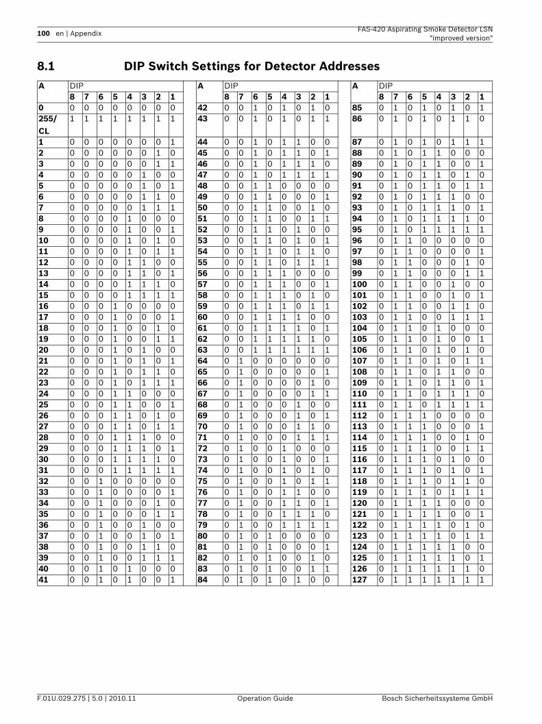
100 en | Appendix FAS-420 Aspirating Smoke Detector LSN"improved version"
F.01U.029.275 | 5.0 | 2010.11 Operation Guide Bosch Sicherheitssysteme GmbH
8.1 DIP Switch Settings for Detector AddressesA DIP A DIP A DIP
8 7 6 5 4 3 2 1 8 7 6 5 4 3 2 1 8 7 6 5 4 3 2 10 0 0 0 0 0 0 0 0 42 0 0 1 0 1 0 1 0 85 0 1 0 1 0 1 0 1255/CL
1 1 1 1 1 1 1 1 43 0 0 1 0 1 0 1 1 86 0 1 0 1 0 1 1 0
1 0 0 0 0 0 0 0 1 44 0 0 1 0 1 1 0 0 87 0 1 0 1 0 1 1 12 0 0 0 0 0 0 1 0 45 0 0 1 0 1 1 0 1 88 0 1 0 1 1 0 0 03 0 0 0 0 0 0 1 1 46 0 0 1 0 1 1 1 0 89 0 1 0 1 1 0 0 14 0 0 0 0 0 1 0 0 47 0 0 1 0 1 1 1 1 90 0 1 0 1 1 0 1 05 0 0 0 0 0 1 0 1 48 0 0 1 1 0 0 0 0 91 0 1 0 1 1 0 1 16 0 0 0 0 0 1 1 0 49 0 0 1 1 0 0 0 1 92 0 1 0 1 1 1 0 07 0 0 0 0 0 1 1 1 50 0 0 1 1 0 0 1 0 93 0 1 0 1 1 1 0 18 0 0 0 0 1 0 0 0 51 0 0 1 1 0 0 1 1 94 0 1 0 1 1 1 1 09 0 0 0 0 1 0 0 1 52 0 0 1 1 0 1 0 0 95 0 1 0 1 1 1 1 110 0 0 0 0 1 0 1 0 53 0 0 1 1 0 1 0 1 96 0 1 1 0 0 0 0 011 0 0 0 0 1 0 1 1 54 0 0 1 1 0 1 1 0 97 0 1 1 0 0 0 0 112 0 0 0 0 1 1 0 0 55 0 0 1 1 0 1 1 1 98 0 1 1 0 0 0 1 013 0 0 0 0 1 1 0 1 56 0 0 1 1 1 0 0 0 99 0 1 1 0 0 0 1 114 0 0 0 0 1 1 1 0 57 0 0 1 1 1 0 0 1 100 0 1 1 0 0 1 0 015 0 0 0 0 1 1 1 1 58 0 0 1 1 1 0 1 0 101 0 1 1 0 0 1 0 116 0 0 0 1 0 0 0 0 59 0 0 1 1 1 0 1 1 102 0 1 1 0 0 1 1 017 0 0 0 1 0 0 0 1 60 0 0 1 1 1 1 0 0 103 0 1 1 0 0 1 1 118 0 0 0 1 0 0 1 0 61 0 0 1 1 1 1 0 1 104 0 1 1 0 1 0 0 019 0 0 0 1 0 0 1 1 62 0 0 1 1 1 1 1 0 105 0 1 1 0 1 0 0 120 0 0 0 1 0 1 0 0 63 0 0 1 1 1 1 1 1 106 0 1 1 0 1 0 1 021 0 0 0 1 0 1 0 1 64 0 1 0 0 0 0 0 0 107 0 1 1 0 1 0 1 122 0 0 0 1 0 1 1 0 65 0 1 0 0 0 0 0 1 108 0 1 1 0 1 1 0 023 0 0 0 1 0 1 1 1 66 0 1 0 0 0 0 1 0 109 0 1 1 0 1 1 0 124 0 0 0 1 1 0 0 0 67 0 1 0 0 0 0 1 1 110 0 1 1 0 1 1 1 025 0 0 0 1 1 0 0 1 68 0 1 0 0 0 1 0 0 111 0 1 1 0 1 1 1 126 0 0 0 1 1 0 1 0 69 0 1 0 0 0 1 0 1 112 0 1 1 1 0 0 0 027 0 0 0 1 1 0 1 1 70 0 1 0 0 0 1 1 0 113 0 1 1 1 0 0 0 128 0 0 0 1 1 1 0 0 71 0 1 0 0 0 1 1 1 114 0 1 1 1 0 0 1 029 0 0 0 1 1 1 0 1 72 0 1 0 0 1 0 0 0 115 0 1 1 1 0 0 1 130 0 0 0 1 1 1 1 0 73 0 1 0 0 1 0 0 1 116 0 1 1 1 0 1 0 031 0 0 0 1 1 1 1 1 74 0 1 0 0 1 0 1 0 117 0 1 1 1 0 1 0 132 0 0 1 0 0 0 0 0 75 0 1 0 0 1 0 1 1 118 0 1 1 1 0 1 1 033 0 0 1 0 0 0 0 1 76 0 1 0 0 1 1 0 0 119 0 1 1 1 0 1 1 134 0 0 1 0 0 0 1 0 77 0 1 0 0 1 1 0 1 120 0 1 1 1 1 0 0 035 0 0 1 0 0 0 1 1 78 0 1 0 0 1 1 1 0 121 0 1 1 1 1 0 0 136 0 0 1 0 0 1 0 0 79 0 1 0 0 1 1 1 1 122 0 1 1 1 1 0 1 037 0 0 1 0 0 1 0 1 80 0 1 0 1 0 0 0 0 123 0 1 1 1 1 0 1 138 0 0 1 0 0 1 1 0 81 0 1 0 1 0 0 0 1 124 0 1 1 1 1 1 0 039 0 0 1 0 0 1 1 1 82 0 1 0 1 0 0 1 0 125 0 1 1 1 1 1 0 140 0 0 1 0 1 0 0 0 83 0 1 0 1 0 0 1 1 126 0 1 1 1 1 1 1 041 0 0 1 0 1 0 0 1 84 0 1 0 1 0 1 0 0 127 0 1 1 1 1 1 1 1
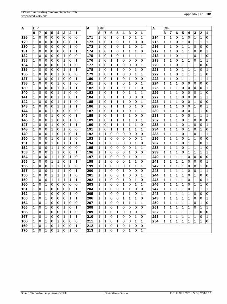
FAS-420 Aspirating Smoke Detector LSN "improved version"
Appendix | en 101
Bosch Sicherheitssysteme GmbH Operation Guide F.01U.029.275 | 5.0 | 2010.11
A DIP A DIP A DIP8 7 6 5 4 3 2 1 8 7 6 5 4 3 2 1 8 7 6 5 4 3 2 1
128 1 0 0 0 0 0 0 0 171 1 0 1 0 1 0 1 1 214 1 1 0 1 0 1 1 0129 1 0 0 0 0 0 0 1 172 1 0 1 0 1 1 0 0 215 1 1 0 1 0 1 1 1130 1 0 0 0 0 0 1 0 173 1 0 1 0 1 1 0 1 216 1 1 0 1 1 0 0 0131 1 0 0 0 0 0 1 1 174 1 0 1 0 1 1 1 0 217 1 1 0 1 1 0 0 1132 1 0 0 0 0 1 0 0 175 1 0 1 0 1 1 1 1 218 1 1 0 1 1 0 1 0133 1 0 0 0 0 1 0 1 176 1 0 1 1 0 0 0 0 219 1 1 0 1 1 0 1 1134 1 0 0 0 0 1 1 0 177 1 0 1 1 0 0 0 1 220 1 1 0 1 1 1 0 0135 1 0 0 0 0 1 1 1 178 1 0 1 1 0 0 1 0 221 1 1 0 1 1 1 0 1136 1 0 0 0 1 0 0 0 179 1 0 1 1 0 0 1 1 222 1 1 0 1 1 1 1 0137 1 0 0 0 1 0 0 1 180 1 0 1 1 0 1 0 0 223 1 1 0 1 1 1 1 1138 1 0 0 0 1 0 1 0 181 1 0 1 1 0 1 0 1 224 1 1 1 0 0 0 0 0139 1 0 0 0 1 0 1 1 182 1 0 1 1 0 1 1 0 225 1 1 1 0 0 0 0 1140 1 0 0 0 1 1 0 0 183 1 0 1 1 0 1 1 1 226 1 1 1 0 0 0 1 0141 1 0 0 0 1 1 0 1 184 1 0 1 1 1 0 0 0 227 1 1 1 0 0 0 1 1142 1 0 0 0 1 1 1 0 185 1 0 1 1 1 0 0 1 228 1 1 1 0 0 1 0 0143 1 0 0 0 1 1 1 1 186 1 0 1 1 1 0 1 0 229 1 1 1 0 0 1 0 1144 1 0 0 1 0 0 0 0 187 1 0 1 1 1 0 1 1 230 1 1 1 0 0 1 1 0145 1 0 0 1 0 0 0 1 188 1 0 1 1 1 1 0 0 231 1 1 1 0 0 1 1 1146 1 0 0 1 0 0 1 0 189 1 0 1 1 1 1 0 1 232 1 1 1 0 1 0 0 0147 1 0 0 1 0 0 1 1 190 1 0 1 1 1 1 1 0 233 1 1 1 0 1 0 0 1148 1 0 0 1 0 1 0 0 191 1 0 1 1 1 1 1 1 234 1 1 1 0 1 0 1 0149 1 0 0 1 0 1 0 1 192 1 1 0 0 0 0 0 0 235 1 1 1 0 1 0 1 1150 1 0 0 1 0 1 1 0 193 1 1 0 0 0 0 0 1 236 1 1 1 0 1 1 0 0151 1 0 0 1 0 1 1 1 194 1 1 0 0 0 0 1 0 237 1 1 1 0 1 1 0 1152 1 0 0 1 1 0 0 0 195 1 1 0 0 0 0 1 1 238 1 1 1 0 1 1 1 0153 1 0 0 1 1 0 0 1 196 1 1 0 0 0 1 0 0 239 1 1 1 0 1 1 1 1154 1 0 0 1 1 0 1 0 197 1 1 0 0 0 1 0 1 240 1 1 1 1 0 0 0 0155 1 0 0 1 1 0 1 1 198 1 1 0 0 0 1 1 0 241 1 1 1 1 0 0 0 1156 1 0 0 1 1 1 0 0 199 1 1 0 0 0 1 1 1 242 1 1 1 1 0 0 1 0157 1 0 0 1 1 1 0 1 200 1 1 0 0 1 0 0 0 243 1 1 1 1 0 0 1 1158 1 0 0 1 1 1 1 0 201 1 1 0 0 1 0 0 1 244 1 1 1 1 0 1 0 0159 1 0 0 1 1 1 1 1 202 1 1 0 0 1 0 1 0 245 1 1 1 1 0 1 0 1160 1 0 1 0 0 0 0 0 203 1 1 0 0 1 0 1 1 246 1 1 1 1 0 1 1 0161 1 0 1 0 0 0 0 1 204 1 1 0 0 1 1 0 0 247 1 1 1 1 0 1 1 1162 1 0 1 0 0 0 1 0 205 1 1 0 0 1 1 0 1 248 1 1 1 1 1 0 0 0163 1 0 1 0 0 0 1 1 206 1 1 0 0 1 1 1 0 249 1 1 1 1 1 0 0 1164 1 0 1 0 0 1 0 0 207 1 1 0 0 1 1 1 1 250 1 1 1 1 1 0 1 0165 1 0 1 0 0 1 0 1 208 1 1 0 1 0 0 0 0 251 1 1 1 1 1 0 1 1166 1 0 1 0 0 1 1 0 209 1 1 0 1 0 0 0 1 252 1 1 1 1 1 1 0 0167 1 0 1 0 0 1 1 1 210 1 1 0 1 0 0 1 0 253 1 1 1 1 1 1 0 1168 1 0 1 0 1 0 0 0 211 1 1 0 1 0 0 1 1 254 1 1 1 1 1 1 1 0169 1 0 1 0 1 0 0 1 212 1 1 0 1 0 1 0 0170 1 0 1 0 1 0 1 0 213 1 1 0 1 0 1 0 1
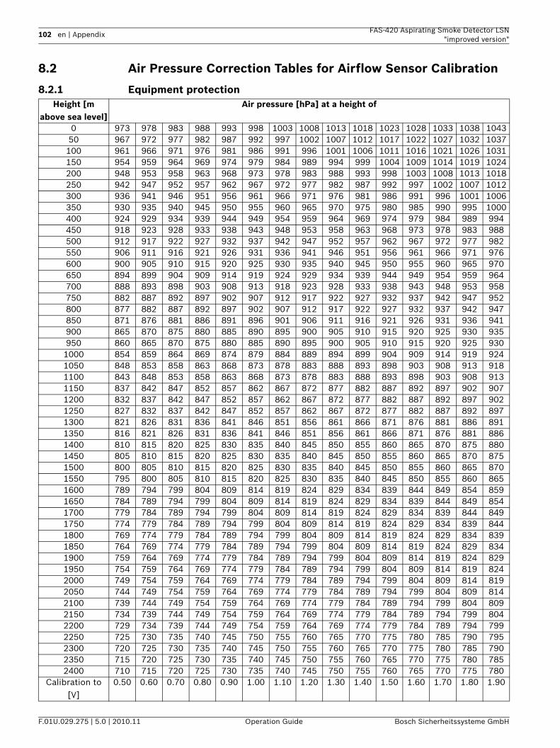
102 en | Appendix FAS-420 Aspirating Smoke Detector LSN"improved version"
F.01U.029.275 | 5.0 | 2010.11 Operation Guide Bosch Sicherheitssysteme GmbH
8.2 Air Pressure Correction Tables for Airflow Sensor Calibration
8.2.1 Equipment protectionHeight [m
above sea level]Air pressure [hPa] at a height of
0 973 978 983 988 993 998 1003 1008 1013 1018 1023 1028 1033 1038 104350 967 972 977 982 987 992 997 1002 1007 1012 1017 1022 1027 1032 1037100 961 966 971 976 981 986 991 996 1001 1006 1011 1016 1021 1026 1031150 954 959 964 969 974 979 984 989 994 999 1004 1009 1014 1019 1024200 948 953 958 963 968 973 978 983 988 993 998 1003 1008 1013 1018250 942 947 952 957 962 967 972 977 982 987 992 997 1002 1007 1012300 936 941 946 951 956 961 966 971 976 981 986 991 996 1001 1006350 930 935 940 945 950 955 960 965 970 975 980 985 990 995 1000400 924 929 934 939 944 949 954 959 964 969 974 979 984 989 994450 918 923 928 933 938 943 948 953 958 963 968 973 978 983 988500 912 917 922 927 932 937 942 947 952 957 962 967 972 977 982550 906 911 916 921 926 931 936 941 946 951 956 961 966 971 976600 900 905 910 915 920 925 930 935 940 945 950 955 960 965 970650 894 899 904 909 914 919 924 929 934 939 944 949 954 959 964700 888 893 898 903 908 913 918 923 928 933 938 943 948 953 958750 882 887 892 897 902 907 912 917 922 927 932 937 942 947 952800 877 882 887 892 897 902 907 912 917 922 927 932 937 942 947850 871 876 881 886 891 896 901 906 911 916 921 926 931 936 941900 865 870 875 880 885 890 895 900 905 910 915 920 925 930 935950 860 865 870 875 880 885 890 895 900 905 910 915 920 925 9301000 854 859 864 869 874 879 884 889 894 899 904 909 914 919 9241050 848 853 858 863 868 873 878 883 888 893 898 903 908 913 9181100 843 848 853 858 863 868 873 878 883 888 893 898 903 908 9131150 837 842 847 852 857 862 867 872 877 882 887 892 897 902 9071200 832 837 842 847 852 857 862 867 872 877 882 887 892 897 9021250 827 832 837 842 847 852 857 862 867 872 877 882 887 892 8971300 821 826 831 836 841 846 851 856 861 866 871 876 881 886 8911350 816 821 826 831 836 841 846 851 856 861 866 871 876 881 8861400 810 815 820 825 830 835 840 845 850 855 860 865 870 875 8801450 805 810 815 820 825 830 835 840 845 850 855 860 865 870 8751500 800 805 810 815 820 825 830 835 840 845 850 855 860 865 8701550 795 800 805 810 815 820 825 830 835 840 845 850 855 860 8651600 789 794 799 804 809 814 819 824 829 834 839 844 849 854 8591650 784 789 794 799 804 809 814 819 824 829 834 839 844 849 8541700 779 784 789 794 799 804 809 814 819 824 829 834 839 844 8491750 774 779 784 789 794 799 804 809 814 819 824 829 834 839 8441800 769 774 779 784 789 794 799 804 809 814 819 824 829 834 8391850 764 769 774 779 784 789 794 799 804 809 814 819 824 829 8341900 759 764 769 774 779 784 789 794 799 804 809 814 819 824 8291950 754 759 764 769 774 779 784 789 794 799 804 809 814 819 8242000 749 754 759 764 769 774 779 784 789 794 799 804 809 814 8192050 744 749 754 759 764 769 774 779 784 789 794 799 804 809 8142100 739 744 749 754 759 764 769 774 779 784 789 794 799 804 8092150 734 739 744 749 754 759 764 769 774 779 784 789 794 799 8042200 729 734 739 744 749 754 759 764 769 774 779 784 789 794 7992250 725 730 735 740 745 750 755 760 765 770 775 780 785 790 7952300 720 725 730 735 740 745 750 755 760 765 770 775 780 785 7902350 715 720 725 730 735 740 745 750 755 760 765 770 775 780 7852400 710 715 720 725 730 735 740 745 750 755 760 765 770 775 780
Calibration to [V]
0.50 0.60 0.70 0.80 0.90 1.00 1.10 1.20 1.30 1.40 1.50 1.60 1.70 1.80 1.90
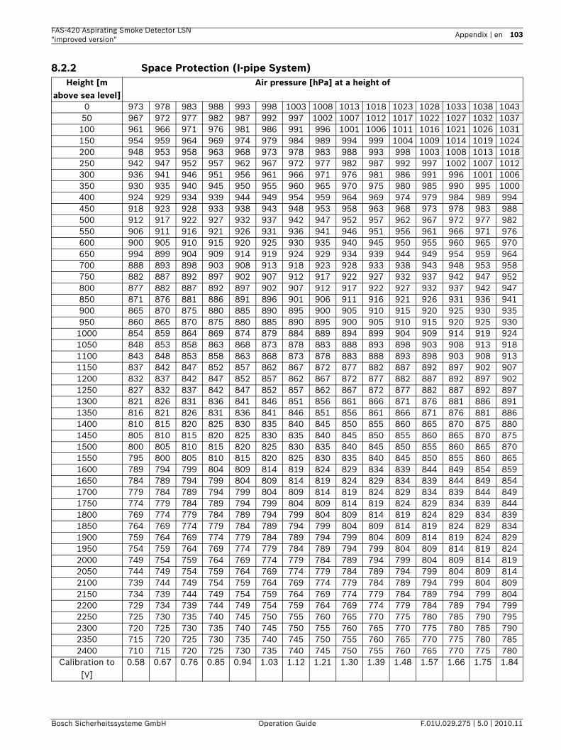
FAS-420 Aspirating Smoke Detector LSN "improved version"
Appendix | en 103
Bosch Sicherheitssysteme GmbH Operation Guide F.01U.029.275 | 5.0 | 2010.11
8.2.2 Space Protection (I-pipe System)Height [m
above sea level]Air pressure [hPa] at a height of
0 973 978 983 988 993 998 1003 1008 1013 1018 1023 1028 1033 1038 104350 967 972 977 982 987 992 997 1002 1007 1012 1017 1022 1027 1032 1037100 961 966 971 976 981 986 991 996 1001 1006 1011 1016 1021 1026 1031150 954 959 964 969 974 979 984 989 994 999 1004 1009 1014 1019 1024200 948 953 958 963 968 973 978 983 988 993 998 1003 1008 1013 1018250 942 947 952 957 962 967 972 977 982 987 992 997 1002 1007 1012300 936 941 946 951 956 961 966 971 976 981 986 991 996 1001 1006350 930 935 940 945 950 955 960 965 970 975 980 985 990 995 1000400 924 929 934 939 944 949 954 959 964 969 974 979 984 989 994450 918 923 928 933 938 943 948 953 958 963 968 973 978 983 988500 912 917 922 927 932 937 942 947 952 957 962 967 972 977 982550 906 911 916 921 926 931 936 941 946 951 956 961 966 971 976600 900 905 910 915 920 925 930 935 940 945 950 955 960 965 970650 994 899 904 909 914 919 924 929 934 939 944 949 954 959 964700 888 893 898 903 908 913 918 923 928 933 938 943 948 953 958750 882 887 892 897 902 907 912 917 922 927 932 937 942 947 952800 877 882 887 892 897 902 907 912 917 922 927 932 937 942 947850 871 876 881 886 891 896 901 906 911 916 921 926 931 936 941900 865 870 875 880 885 890 895 900 905 910 915 920 925 930 935950 860 865 870 875 880 885 890 895 900 905 910 915 920 925 9301000 854 859 864 869 874 879 884 889 894 899 904 909 914 919 9241050 848 853 858 863 868 873 878 883 888 893 898 903 908 913 9181100 843 848 853 858 863 868 873 878 883 888 893 898 903 908 9131150 837 842 847 852 857 862 867 872 877 882 887 892 897 902 9071200 832 837 842 847 852 857 862 867 872 877 882 887 892 897 9021250 827 832 837 842 847 852 857 862 867 872 877 882 887 892 8971300 821 826 831 836 841 846 851 856 861 866 871 876 881 886 8911350 816 821 826 831 836 841 846 851 856 861 866 871 876 881 8861400 810 815 820 825 830 835 840 845 850 855 860 865 870 875 8801450 805 810 815 820 825 830 835 840 845 850 855 860 865 870 8751500 800 805 810 815 820 825 830 835 840 845 850 855 860 865 8701550 795 800 805 810 815 820 825 830 835 840 845 850 855 860 8651600 789 794 799 804 809 814 819 824 829 834 839 844 849 854 8591650 784 789 794 799 804 809 814 819 824 829 834 839 844 849 8541700 779 784 789 794 799 804 809 814 819 824 829 834 839 844 8491750 774 779 784 789 794 799 804 809 814 819 824 829 834 839 8441800 769 774 779 784 789 794 799 804 809 814 819 824 829 834 8391850 764 769 774 779 784 789 794 799 804 809 814 819 824 829 8341900 759 764 769 774 779 784 789 794 799 804 809 814 819 824 8291950 754 759 764 769 774 779 784 789 794 799 804 809 814 819 8242000 749 754 759 764 769 774 779 784 789 794 799 804 809 814 8192050 744 749 754 759 764 769 774 779 784 789 794 799 804 809 8142100 739 744 749 754 759 764 769 774 779 784 789 794 799 804 8092150 734 739 744 749 754 759 764 769 774 779 784 789 794 799 8042200 729 734 739 744 749 754 759 764 769 774 779 784 789 794 7992250 725 730 735 740 745 750 755 760 765 770 775 780 785 790 7952300 720 725 730 735 740 745 750 755 760 765 770 775 780 785 7902350 715 720 725 730 735 740 745 750 755 760 765 770 775 780 7852400 710 715 720 725 730 735 740 745 750 755 760 765 770 775 780
Calibration to [V]
0.58 0.67 0.76 0.85 0.94 1.03 1.12 1.21 1.30 1.39 1.48 1.57 1.66 1.75 1.84
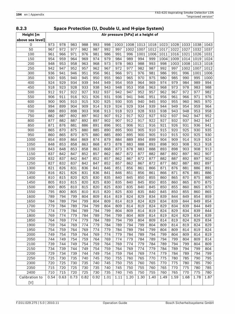
104 en | Appendix FAS-420 Aspirating Smoke Detector LSN"improved version"
F.01U.029.275 | 5.0 | 2010.11 Operation Guide Bosch Sicherheitssysteme GmbH
8.2.3 Space Protection (U, Double U, and H-pipe System)Height [m
above sea level]Air pressure [hPa] at a height of
0 973 978 983 988 993 998 1003 1008 1013 1018 1023 1028 1033 1038 104350 967 972 977 982 987 992 997 1002 1007 1012 1017 1022 1027 1032 1037100 961 966 971 976 981 986 991 996 1001 1006 1011 1016 1021 1026 1031150 954 959 964 969 974 979 984 989 994 999 1004 1009 1014 1019 1024200 948 953 958 963 968 973 978 983 988 993 998 1003 1008 1013 1018250 942 947 952 957 962 967 972 977 982 987 992 997 1002 1007 1012300 936 941 946 951 956 961 966 971 976 981 986 991 996 1001 1006350 930 935 940 945 950 955 960 965 970 975 980 985 990 995 1000400 924 929 934 939 944 949 954 959 964 969 974 979 984 989 994450 918 923 928 933 938 943 948 953 958 963 968 973 978 983 988500 912 917 922 927 932 937 942 947 952 957 962 967 972 977 982550 906 911 916 921 926 931 936 941 946 951 956 961 966 971 976600 900 905 910 915 920 925 930 935 940 945 950 955 960 965 970650 994 899 904 909 914 919 924 929 934 939 944 949 954 959 964700 888 893 898 903 908 913 918 923 928 933 938 943 948 953 958750 882 887 892 897 902 907 912 917 922 927 932 937 942 947 952800 877 882 887 892 897 902 907 912 917 922 927 932 937 942 947850 871 876 881 886 891 896 901 906 911 916 921 926 931 936 941900 865 870 875 880 885 890 895 900 905 910 915 920 925 930 935950 860 865 870 875 880 885 890 895 900 905 910 915 920 925 9301000 854 859 864 869 874 879 884 889 894 899 904 909 914 919 9241050 848 853 858 863 868 873 878 883 888 893 898 903 908 913 9181100 843 848 853 858 863 868 873 878 883 888 893 898 903 908 9131150 837 842 847 852 857 862 867 872 877 882 887 892 897 902 9071200 832 837 842 847 852 857 862 867 872 877 882 887 892 897 9021250 827 832 837 842 847 852 857 862 867 872 877 882 887 892 8971300 821 826 831 836 841 846 851 856 861 866 871 876 881 886 8911350 816 821 826 831 836 841 846 851 856 861 866 871 876 881 8861400 810 815 820 825 830 835 840 845 850 855 860 865 870 875 8801450 805 810 815 820 825 830 835 840 845 850 855 860 865 870 8751500 800 805 810 815 820 825 830 835 840 845 850 855 860 865 8701550 795 800 805 810 815 820 825 830 835 840 845 850 855 860 8651600 789 794 799 804 809 814 819 824 829 834 839 844 849 854 8591650 784 789 794 799 804 809 814 819 824 829 834 839 844 849 8541700 779 784 789 794 799 804 809 814 819 824 829 834 839 844 8491750 774 779 784 789 794 799 804 809 814 819 824 829 834 839 8441800 769 774 779 784 789 794 799 804 809 814 819 824 829 834 8391850 764 769 774 779 784 789 794 799 804 809 814 819 824 829 8341900 759 764 769 774 779 784 789 794 799 804 809 814 819 824 8291950 754 759 764 769 774 779 784 789 794 799 804 809 814 819 8242000 749 754 759 764 769 774 779 784 789 794 799 804 809 814 8192050 744 749 754 759 764 769 774 779 784 789 794 799 804 809 8142100 739 744 749 754 759 764 769 774 779 784 789 794 799 804 8092150 734 739 744 749 754 759 764 769 774 779 784 789 794 799 8042200 729 734 739 744 749 754 759 764 769 774 779 784 789 794 7992250 725 730 735 740 745 750 755 760 765 770 775 780 785 790 7952300 720 725 730 735 740 745 750 755 760 765 770 775 780 785 7902350 715 720 725 730 735 740 745 750 755 760 765 770 775 780 7852400 710 715 720 725 730 735 740 745 750 755 760 765 770 775 780
Calibration to [V]
0.54 0.63 0.73 0.82 0.92 1.01 1.11 1.20 1.30 1.40 1.49 1.59 1.68 1.78 1.87
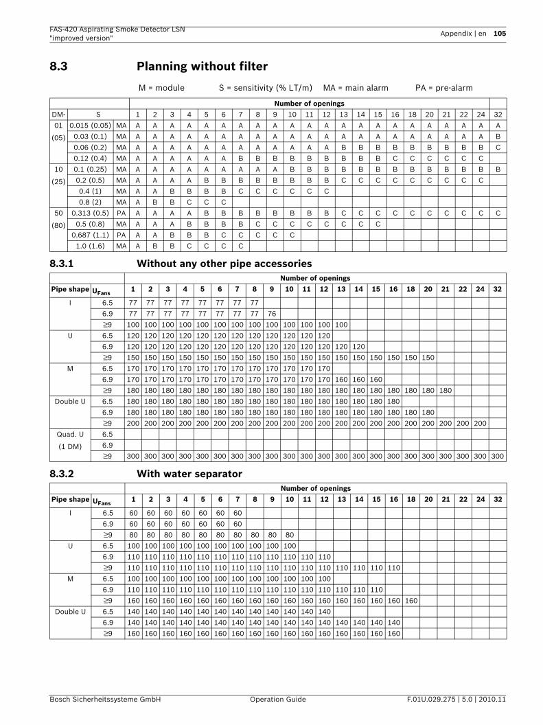
FAS-420 Aspirating Smoke Detector LSN "improved version"
Appendix | en 105
Bosch Sicherheitssysteme GmbH Operation Guide F.01U.029.275 | 5.0 | 2010.11
8.3 Planning without filter
8.3.1 Without any other pipe accessories
8.3.2 With water separator
M = module S = sensitivity (% LT/m) MA = main alarm PA = pre-alarm
Number of openingsDM- S 1 2 3 4 5 6 7 8 9 10 11 12 13 14 15 16 18 20 21 22 24 32
01
(05)
0.015 (0.05) MA A A A A A A A A A A A A A A A A A A A A A A
0.03 (0.1) MA A A A A A A A A A A A A A A A A A A A A A B
0.06 (0.2) MA A A A A A A A A A A A A B B B B B B B B B C
0.12 (0.4) MA A A A A A A B B B B B B B B B C C C C C C
10
(25)
0.1 (0.25) MA A A A A A A A A A B B B B B B B B B B B B B
0.2 (0.5) MA A A A A B B B B B B B B C C C C C C C C C
0.4 (1) MA A A B B B B C C C C C C
0.8 (2) MA A B B C C C
50
(80)
0.313 (0.5) PA A A A A B B B B B B B B C C C C C C C C C C
0.5 (0.8) MA A A A B B B B C C C C C C C C
0.687 (1.1) PA A A B B B C C C C C
1.0 (1.6) MA A B B C C C C
Number of openingsPipe shape UFans
1 2 3 4 5 6 7 8 9 10 11 12 13 14 15 16 18 20 21 22 24 32
I 6.5 77 77 77 77 77 77 77 77
6.9 77 77 77 77 77 77 77 77 76
≥9 100 100 100 100 100 100 100 100 100 100 100 100 100
U 6.5 120 120 120 120 120 120 120 120 120 120 120 120
6.9 120 120 120 120 120 120 120 120 120 120 120 120 120 120
≥9 150 150 150 150 150 150 150 150 150 150 150 150 150 150 150 150 150 150
M 6.5 170 170 170 170 170 170 170 170 170 170 170 170
6.9 170 170 170 170 170 170 170 170 170 170 170 170 160 160 160
≥9 180 180 180 180 180 180 180 180 180 180 180 180 180 180 180 180 180 180 180
Double U 6.5 180 180 180 180 180 180 180 180 180 180 180 180 180 180 180 180
6.9 180 180 180 180 180 180 180 180 180 180 180 180 180 180 180 180 180 180
≥9 200 200 200 200 200 200 200 200 200 200 200 200 200 200 200 200 200 200 200 200 200
Quad. U
(1 DM)
6.5
6.9
≥9 300 300 300 300 300 300 300 300 300 300 300 300 300 300 300 300 300 300 300 300 300 300
Number of openingsPipe shape UFans
1 2 3 4 5 6 7 8 9 10 11 12 13 14 15 16 18 20 21 22 24 32
I 6.5 60 60 60 60 60 60 60
6.9 60 60 60 60 60 60 60
≥9 80 80 80 80 80 80 80 80 80 80
U 6.5 100 100 100 100 100 100 100 100 100 100
6.9 110 110 110 110 110 110 110 110 110 110 110 110
≥9 110 110 110 110 110 110 110 110 110 110 110 110 110 110 110 110
M 6.5 100 100 100 100 100 100 100 100 100 100 100 100
6.9 110 110 110 110 110 110 110 110 110 110 110 110 110 110 110
≥9 160 160 160 160 160 160 160 160 160 160 160 160 160 160 160 160 160
Double U 6.5 140 140 140 140 140 140 140 140 140 140 140 140
6.9 140 140 140 140 140 140 140 140 140 140 140 140 140 140 140 140
≥9 160 160 160 160 160 160 160 160 160 160 160 160 160 160 160 160

106 en | Appendix FAS-420 Aspirating Smoke Detector LSN"improved version"
F.01U.029.275 | 5.0 | 2010.11 Operation Guide Bosch Sicherheitssysteme GmbH
8.3.3 With detonation safety barrier Number of openings
Pipe shape UFans1 2 3 4 5 6 7 8 9 10 11 12 13 14 15 16 18 20 21 22 24 32
I 6.5 46 46 46 46
6.9 46 46 46 46 38
≥9 68 68 68 68 68 68
U 6.5 60 60 60 60 60 60
6.9 60 60 60 60 60 60
≥9 60 60 60 60 60 60 60 60
M 6.5 80 80 80 80 80 80
6.9 80 80 80 80 80 80 70 70 70
≥9 120 120 120 120 120 120 120 120 120
Double U 6.5 80 80 80 80
6.9 80 80 80 80 80 80 80 80
≥9 100 100 100 100 100 100 100 100
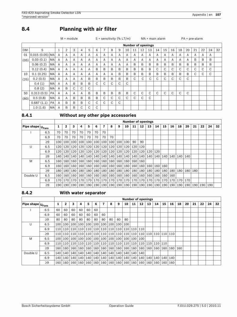
FAS-420 Aspirating Smoke Detector LSN "improved version"
Appendix | en 107
Bosch Sicherheitssysteme GmbH Operation Guide F.01U.029.275 | 5.0 | 2010.11
8.4 Planning with air filter
8.4.1 Without any other pipe accessories
8.4.2 With water separator
M = module S = sensitivity (% LT/m) MA = main alarm PA = pre-alarm
Number of openingsDM- S 1 2 3 4 5 6 7 8 9 10 11 12 13 14 15 16 18 20 21 22 24 32
01
(05)
0.015 (0.05) MA A A A A A A A A A A A A A A A A A A A A A
0.03 (0.1) MA A A A A A A A A A A A A A A A A A A B B B
0.06 (0.2) MA A A A A A A A A A A B B B B B B B B B B B
0.12 (0.4) MA A A A A A B B B B B B B B C C C C C C C C
10
(25)
0.1 (0.25) MA A A A A A A A A B B B B B B B B B B C C C
0.2 (0.5) MA A A A A B B B B B B C C C C C C C C
0.4 (1) MA A A B B B C C C C C
0.8 (2) MA A B C C C
50
(80)
0.313 (0.5) PA A A A A B B B B B B C C C C C C C C
0.5 (0.8) MA A A B B B B C C C C C C C
0.687 (1.1) PA A B B B C C C C C
1.0 (1.6) MA A B B C C C
Number of openingsPipe shape UFans
1 2 3 4 5 6 7 8 9 10 11 12 13 14 15 16 18 20 21 22 24 32
I 6.5 70 70 70 70 70 70 70
6.9 70 70 70 70 70 70 70 70
≥9 100 100 100 100 100 100 100 100 100 100 90 90
U 6.5 120 120 120 120 120 120 120 120 120 120 120 120
6.9 120 120 120 120 120 120 120 120 120 120 120 120 120 120
≥9 140 140 140 140 140 140 140 140 140 140 140 140 140 140 140 140 140 140
M 6.5 160 160 160 160 160 160 160 160 160 160 160 160
6.9 160 160 160 160 160 160 160 160 160 160 160 160 160 160 160
≥9 180 180 180 180 180 180 180 180 180 180 180 180 180 180 180 180 180 180 180
Double U 6.5 160 160 160 160 160 160 160 160 160 160 160 160 160 160 160 160
6.9 170 170 170 170 170 170 170 170 170 170 170 170 170 170 170 170 170 170
≥9 190 190 190 190 190 190 190 190 190 190 190 190 190 190 190 190 190 190 190 190 190
Number of openingsPipe shape UFans
1 2 3 4 5 6 7 8 9 10 11 12 13 14 15 16 18 20 21 22 24 32
I 6.5 60 60 60 60 60 60
6.9 60 60 60 60 60 60 60
≥9 80 80 80 80 80 80 80 80 80 80
U 6.5 100 100 100 100 100 100 100 100 100 100
6.9 110 110 110 110 110 110 110 110 110 110 110 110
≥9 110 110 110 110 110 110 110 110 110 110 110 110 110 110 110 110
M 6.5 100 100 100 100 100 100 100 100 100 100 100 100
6.9 110 110 110 110 110 110 110 110 110 110 110 110 110 110 110
≥9 160 160 160 160 160 160 160 160 160 160 160 160 160 160 160 160 160
Double U 6.5 140 140 140 140 140 140 140 140 140 140 140 140
6.9 140 140 140 140 140 140 140 140 140 140 140 140 140 140 140 140
≥9 160 160 160 160 160 160 160 160 160 160 160 160 160 160 160 160
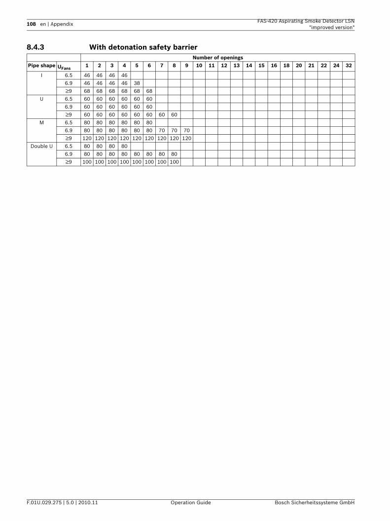
108 en | Appendix FAS-420 Aspirating Smoke Detector LSN"improved version"
F.01U.029.275 | 5.0 | 2010.11 Operation Guide Bosch Sicherheitssysteme GmbH
8.4.3 With detonation safety barrier Number of openings
Pipe shape UFans1 2 3 4 5 6 7 8 9 10 11 12 13 14 15 16 18 20 21 22 24 32
I 6.5 46 46 46 46
6.9 46 46 46 46 38
≥9 68 68 68 68 68 68
U 6.5 60 60 60 60 60 60
6.9 60 60 60 60 60 60
≥9 60 60 60 60 60 60 60 60
M 6.5 80 80 80 80 80 80
6.9 80 80 80 80 80 80 70 70 70
≥9 120 120 120 120 120 120 120 120 120
Double U 6.5 80 80 80 80
6.9 80 80 80 80 80 80 80 80
≥9 100 100 100 100 100 100 100 100
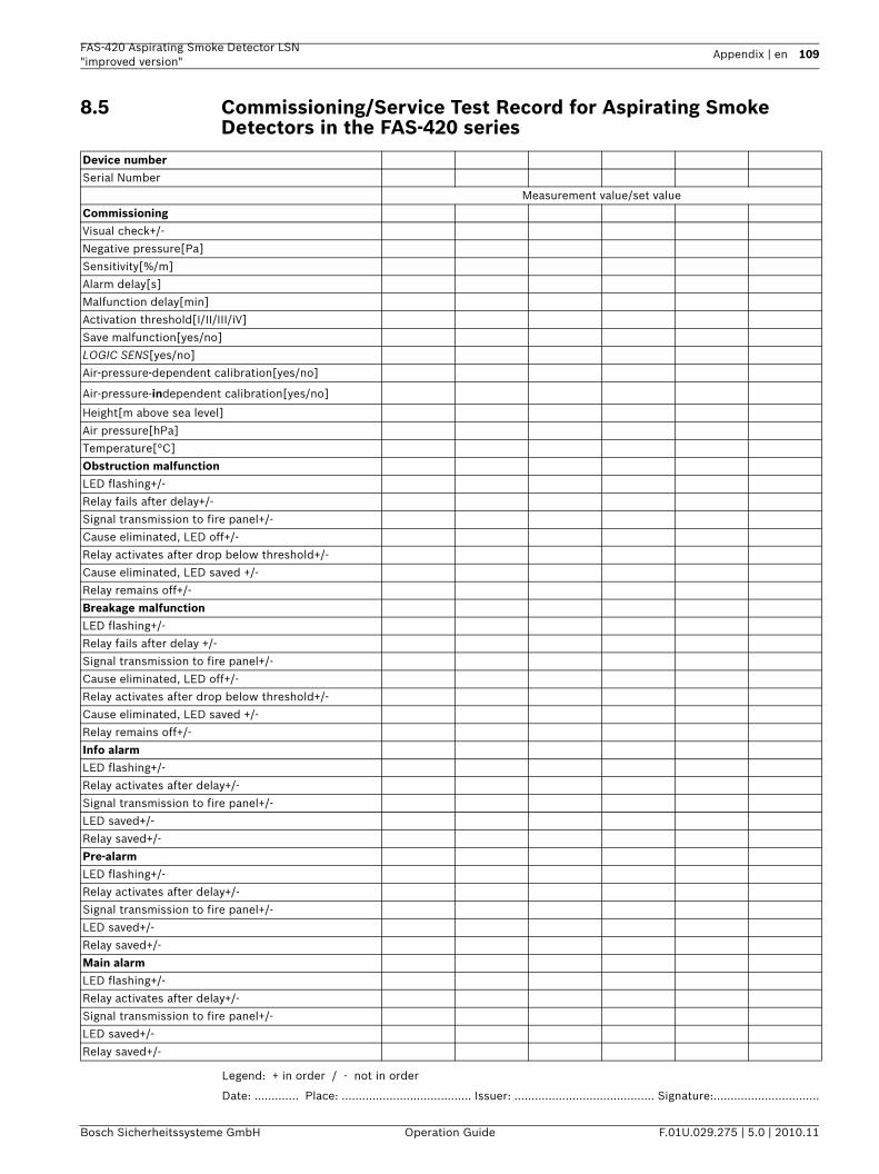
FAS-420 Aspirating Smoke Detector LSN "improved version"
Appendix | en 109
Bosch Sicherheitssysteme GmbH Operation Guide F.01U.029.275 | 5.0 | 2010.11
8.5 Commissioning/Service Test Record for Aspirating Smoke Detectors in the FAS-420 series
Legend: + in order / - not in order
Date: ............. Place: ...................................... Issuer: ......................................... Signature:...............................
Device numberSerial Number
Measurement value/set value
CommissioningVisual check+/-
Negative pressure[Pa]
Sensitivity[%/m]
Alarm delay[s]
Malfunction delay[min]
Activation threshold[I/II/III/iV]
Save malfunction[yes/no]
LOGIC SENS[yes/no]
Air-pressure-dependent calibration[yes/no]
Air-pressure-independent calibration[yes/no]
Height[m above sea level]
Air pressure[hPa]
Temperature[°C]
Obstruction malfunctionLED flashing+/-
Relay fails after delay+/-
Signal transmission to fire panel+/-
Cause eliminated, LED off+/-
Relay activates after drop below threshold+/-
Cause eliminated, LED saved +/-
Relay remains off+/-
Breakage malfunctionLED flashing+/-
Relay fails after delay +/-
Signal transmission to fire panel+/-
Cause eliminated, LED off+/-
Relay activates after drop below threshold+/-
Cause eliminated, LED saved +/-
Relay remains off+/-
Info alarmLED flashing+/-
Relay activates after delay+/-
Signal transmission to fire panel+/-
LED saved+/-
Relay saved+/-
Pre-alarmLED flashing+/-
Relay activates after delay+/-
Signal transmission to fire panel+/-
LED saved+/-
Relay saved+/-
Main alarmLED flashing+/-
Relay activates after delay+/-
Signal transmission to fire panel+/-
LED saved+/-
Relay saved+/-
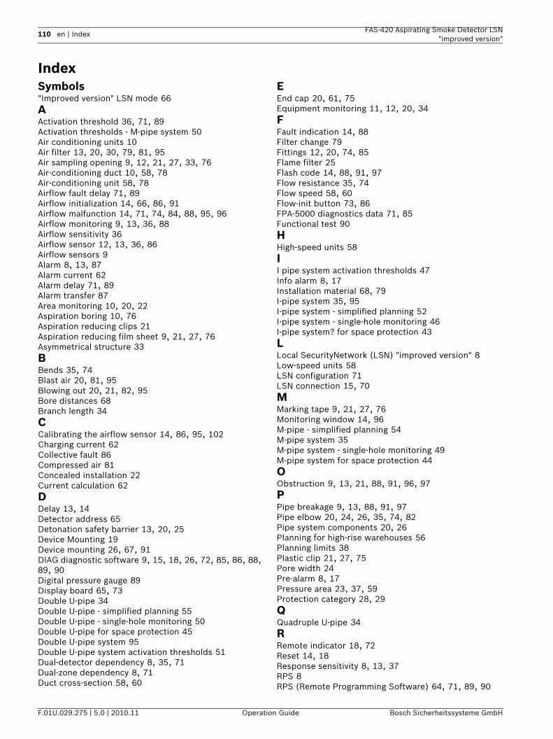
110 en | Index FAS-420 Aspirating Smoke Detector LSN"improved version"
F.01U.029.275 | 5.0 | 2010.11 Operation Guide Bosch Sicherheitssysteme GmbH
IndexSymbols"Improved version" LSN mode 66AActivation threshold 36, 71, 89Activation thresholds - M-pipe system 50Air conditioning units 10Air filter 13, 20, 30, 79, 81, 95Air sampling opening 9, 12, 21, 27, 33, 76Air-conditioning duct 10, 58, 78Air-conditioning unit 58, 78Airflow fault delay 71, 89Airflow initialization 14, 66, 86, 91Airflow malfunction 14, 71, 74, 84, 88, 95, 96Airflow monitoring 9, 13, 36, 88Airflow sensitivity 36Airflow sensor 12, 13, 36, 86Airflow sensors 9Alarm 8, 13, 87Alarm current 62Alarm delay 71, 89Alarm transfer 87Area monitoring 10, 20, 22Aspiration boring 10, 76Aspiration reducing clips 21Aspiration reducing film sheet 9, 21, 27, 76Asymmetrical structure 33BBends 35, 74Blast air 20, 81, 95Blowing out 20, 21, 82, 95Bore distances 68Branch length 34CCalibrating the airflow sensor 14, 86, 95, 102Charging current 62Collective fault 86Compressed air 81Concealed installation 22Current calculation 62DDelay 13, 14Detector address 65Detonation safety barrier 13, 20, 25Device Mounting 19Device mounting 26, 67, 91DIAG diagnostic software 9, 15, 18, 26, 72, 85, 86, 88, 89, 90Digital pressure gauge 89Display board 65, 73Double U-pipe 34Double U-pipe - simplified planning 55Double U-pipe - single-hole monitoring 50Double U-pipe for space protection 45Double U-pipe system 95Double U-pipe system activation thresholds 51Dual-detector dependency 8, 35, 71Dual-zone dependency 8, 71Duct cross-section 58, 60
EEnd cap 20, 61, 75Equipment monitoring 11, 12, 20, 34FFault indication 14, 88Filter change 79Fittings 12, 20, 74, 85Flame filter 25Flash code 14, 88, 91, 97Flow resistance 35, 74Flow speed 58, 60Flow-init button 73, 86FPA-5000 diagnostics data 71, 85Functional test 90HHigh-speed units 58II pipe system activation thresholds 47Info alarm 8, 17Installation material 68, 79I-pipe system 35, 95I-pipe system - simplified planning 52I-pipe system - single-hole monitoring 46I-pipe system? for space protection 43LLocal SecurityNetwork (LSN) "improved version" 8Low-speed units 58LSN configuration 71LSN connection 15, 70MMarking tape 9, 21, 27, 76Monitoring window 14, 96M-pipe - simplified planning 54M-pipe system 35M-pipe system - single-hole monitoring 49M-pipe system for space protection 44OObstruction 9, 13, 21, 88, 91, 96, 97PPipe breakage 9, 13, 88, 91, 97Pipe elbow 20, 24, 26, 35, 74, 82Pipe system components 20, 26Planning for high-rise warehouses 56Planning limits 38Plastic clip 21, 27, 75Pore width 24Pre-alarm 8, 17Pressure area 23, 37, 59Protection category 28, 29QQuadruple U-pipe 34RRemote indicator 18, 72Reset 14, 18Response sensitivity 8, 13, 37RPS 8RPS (Remote Programming Software) 64, 71, 89, 90
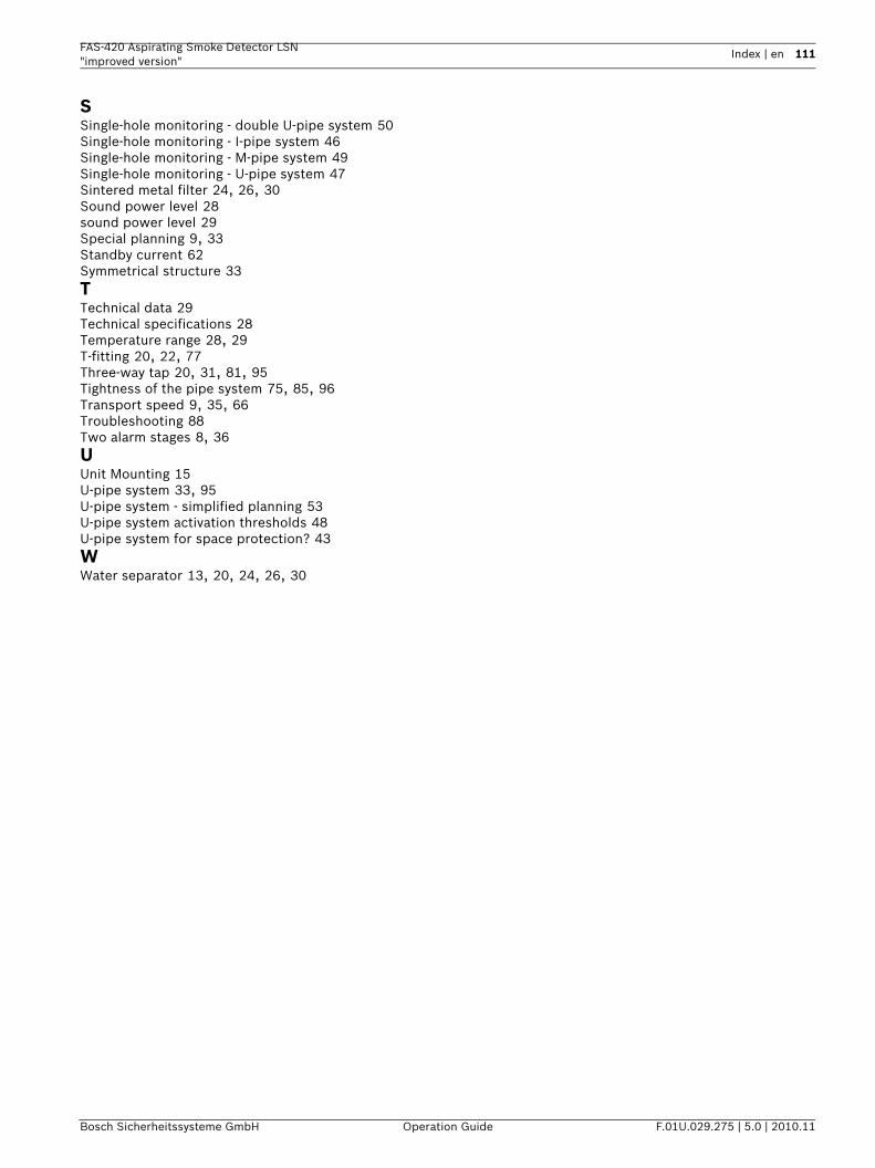
FAS-420 Aspirating Smoke Detector LSN "improved version"
Index | en 111
Bosch Sicherheitssysteme GmbH Operation Guide F.01U.029.275 | 5.0 | 2010.11
SSingle-hole monitoring - double U-pipe system 50Single-hole monitoring - I-pipe system 46Single-hole monitoring - M-pipe system 49Single-hole monitoring - U-pipe system 47Sintered metal filter 24, 26, 30Sound power level 28sound power level 29Special planning 9, 33Standby current 62Symmetrical structure 33TTechnical data 29Technical specifications 28Temperature range 28, 29T-fitting 20, 22, 77Three-way tap 20, 31, 81, 95Tightness of the pipe system 75, 85, 96Transport speed 9, 35, 66Troubleshooting 88Two alarm stages 8, 36UUnit Mounting 15U-pipe system 33, 95U-pipe system - simplified planning 53U-pipe system activation thresholds 48U-pipe system for space protection? 43WWater separator 13, 20, 24, 26, 30

Bosch Sicherheitssysteme GmbHWerner-von-Siemens-Ring 10D-85630 GrasbrunnGermanywww.boschsecurity.com© Bosch Sicherheitssysteme GmbH, 2010