farris engineering - · pdf fileapi 521 is designed to aid in the selection of the system that...
TRANSCRIPT
1 | March 31, 2015 | Proprietary © 2014 Curtiss-Wright
Farris Engineering
Codes & Standards

2 | March 31, 2015 | Proprietary © 2014 Curtiss-Wright
The aim of this presentation is to
discuss the Codes & Standards which
apply to pressure relief valves.

3 | March 31, 2015 | Proprietary © Curtiss-Wright
American Society of Mechanical Engineers
The ASME establishes rules of safety governing the design, the fabrication and the inspection during construction of boilers and unfired pressure vessels, and interprets these rules when questions arise regarding their intent.
Different Sections of ASME Code deal with the manufacture of safety valves:
– ASME Code Section I
– ASME Code Section II
– ASME Code Section III
– ASME Code Section VIII
4 | March 31, 2015 | Proprietary © Curtiss-Wright
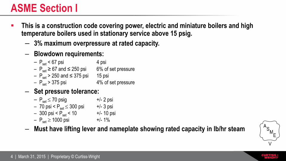
This is a construction code covering power, electric and miniature boilers and high temperature boilers used in stationary service above 15 psig.
– 3% maximum overpressure at rated capacity.
– Blowdown requirements: – Pset < 67 psi 4 psi
– Pset ≥ 67 and ≤ 250 psi 6% of set pressure
– Pset > 250 and ≤ 375 psi 15 psi
– Pset > 375 psi 4% of set pressure
– Set pressure tolerance: – Pset 70 psig +/- 2 psi
– 70 psi < Pset 300 psi +/- 3 psi
– 300 psi < Pset < 10 +/- 10 psi
– Pset 1000 psi +/- 1%
– Must have lifting lever and nameplate showing rated capacity in lb/hr steam
ASME Section I
5 | March 31, 2015 | Proprietary © Curtiss-Wright
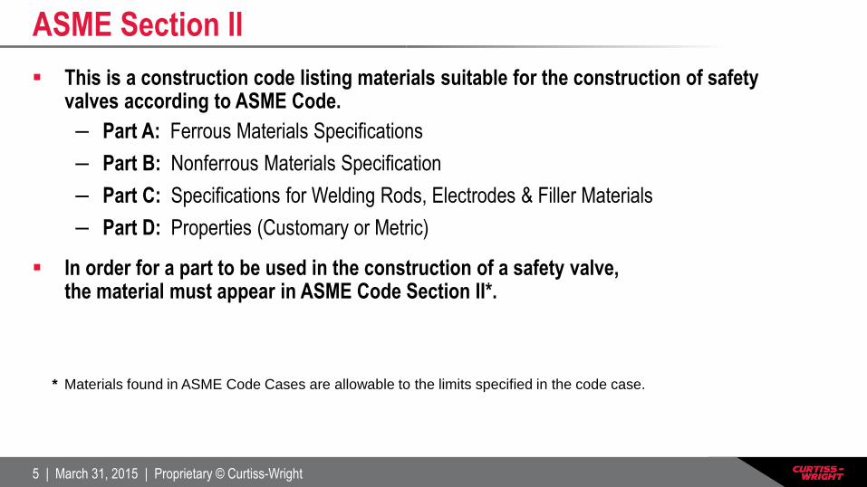
This is a construction code listing materials suitable for the construction of safety valves according to ASME Code.
– Part A: Ferrous Materials Specifications
– Part B: Nonferrous Materials Specification
– Part C: Specifications for Welding Rods, Electrodes & Filler Materials
– Part D: Properties (Customary or Metric)
In order for a part to be used in the construction of a safety valve, the material must appear in ASME Code Section II*.
* Materials found in ASME Code Cases are allowable to the limits specified in the code case.
ASME Section II
6 | March 31, 2015 | Proprietary © Curtiss-Wright
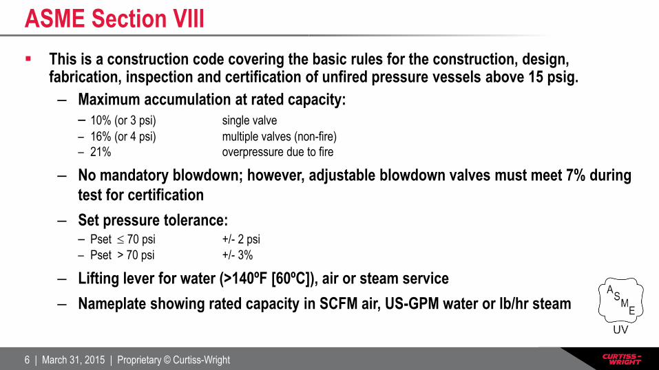
This is a construction code covering the basic rules for the construction, design, fabrication, inspection and certification of unfired pressure vessels above 15 psig.
– Maximum accumulation at rated capacity:
– 10% (or 3 psi) single valve
– 16% (or 4 psi) multiple valves (non-fire)
– 21% overpressure due to fire
– No mandatory blowdown; however, adjustable blowdown valves must meet 7% during
test for certification
– Set pressure tolerance: – Pset 70 psi +/- 2 psi
– Pset > 70 psi +/- 3%
– Lifting lever for water (>140ºF [60ºC]), air or steam service
– Nameplate showing rated capacity in SCFM air, US-GPM water or lb/hr steam
ASME Section VIII
7 | March 31, 2015 | Proprietary © Curtiss-Wright
The NB represents the enforcement agency who assures adherence to provisions of the ASME boiler and pressure vessel codes.
The NB:
– Sets inspection standards
– Qualifies inspectors
– Works for owners, insurers
– Maintains records (Red Book – NB-18)
– Looks into violations
– Covers repair (VR Stamp)
National Board of Boiler & Pressure Vessel Inspectors (NB)
8 | March 31, 2015 | Proprietary © Curtiss-Wright
API publishes several standards dealing with safety valves:
– API 520 Part 1 – Sizing & Selection of Pressure Relief Devices
– API 520 Part 2 – Installation of Pressure Relief Devices
– API 521 – Guide for Pressure-Relieving & Depressurizing Systems
– API 526 – Flanged Steel Safety Relief Valves
– API 527 – Seat Tightness of Pressure Relief Valves
American Petroleum Institute (API)
9 | March 31, 2015 | Proprietary © Curtiss-Wright
API 520 Part 1
Applies to the sizing and selection of pressure relief devices for equipment with an MAWP of 15 psig or greater.
– Protection of unfired vessels
– Basic definitions
– Operational characteristics of pressure relief devices
– Sizing procedures, equations and methods
API 520 Part 2
Covers methods of installation for pressure relief devices on equipment with an MAWP of 15 psig or greater.
API 520
10 | March 31, 2015 | Proprietary © Curtiss-Wright
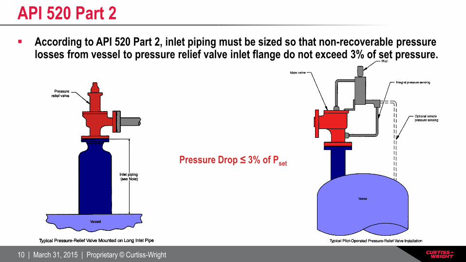
According to API 520 Part 2, inlet piping must be sized so that non-recoverable pressure losses from vessel to pressure relief valve inlet flange do not exceed 3% of set pressure.
API 520 Part 2
Pressure Drop ≤ 3% of Pset

11 | March 31, 2015 | Proprietary © Curtiss-Wright
OUTLET
INLET
AVOID
API 520 Part 2
Install the PRV in an upright, vertical position
12 | March 31, 2015 | Proprietary © Curtiss-Wright
API 521 is designed to aid in the selection of the system that is most appropriate for the risks and circumstances involved in various installations.
This standard provides guidelines for:
– Examining the principal causes of overpressure
– Determining individual relieving rates
• Including fire vapor generation and fire gas expansion
– Selecting and designing disposal systems
API 521
13 | March 31, 2015 | Proprietary © Curtiss-Wright
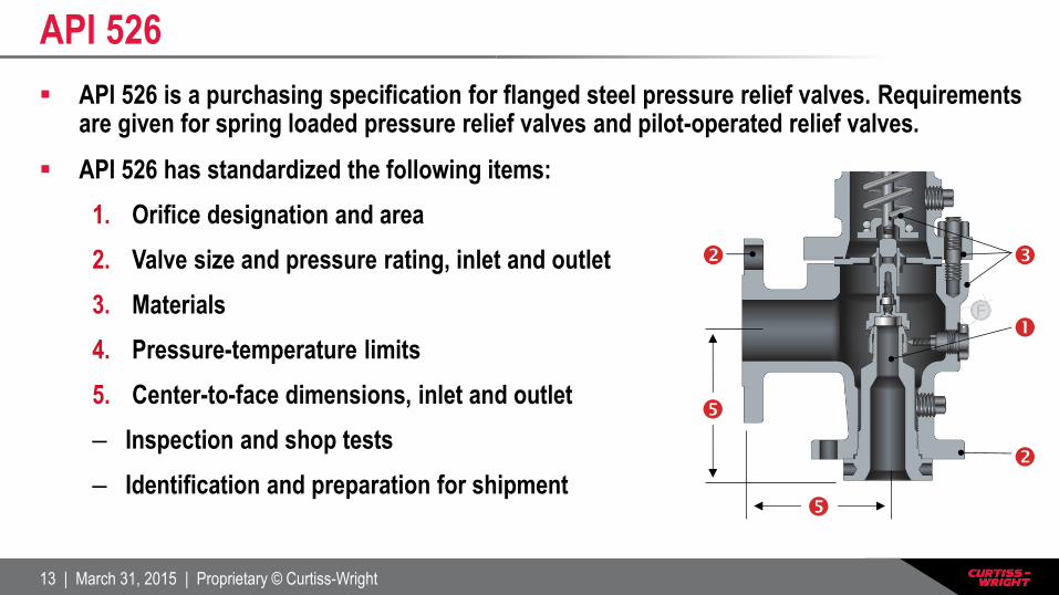
API 526 is a purchasing specification for flanged steel pressure relief valves. Requirements are given for spring loaded pressure relief valves and pilot-operated relief valves.
API 526 has standardized the following items:
1. Orifice designation and area
2. Valve size and pressure rating, inlet and outlet
3. Materials
4. Pressure-temperature limits
5. Center-to-face dimensions, inlet and outlet
– Inspection and shop tests
– Identification and preparation for shipment
API 526

14 | March 31, 2015 | Proprietary © Curtiss-Wright
API 527 describes tests to determine the seat tightness of metal and soft-seated pressure relief valves. Valves of conventional, bellows, and pilot-operated designs are covered. Acceptable leakage rates are defined.
It contains criteria for:
– Testing with air
– Testing with steam
– Testing with water
– Testing with air – another method
API 527

15 | March 31, 2015 | Proprietary © Curtiss-Wright
Required Nameplate Data
16 | March 31, 2015 | Proprietary © Curtiss-Wright
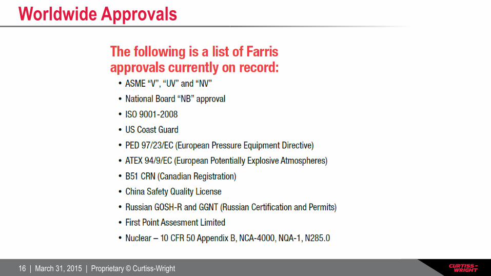
Worldwide Approvals

17 | March 31, 2015 | Proprietary © Curtiss-Wright
Farris Engineering
Terminology
18 | March 31, 2015 | Proprietary © Curtiss-Wright
The aim of this presentation is to
provide an overview of pressure relief
terminology.
19 | March 31, 2015 | Proprietary © Curtiss-Wright
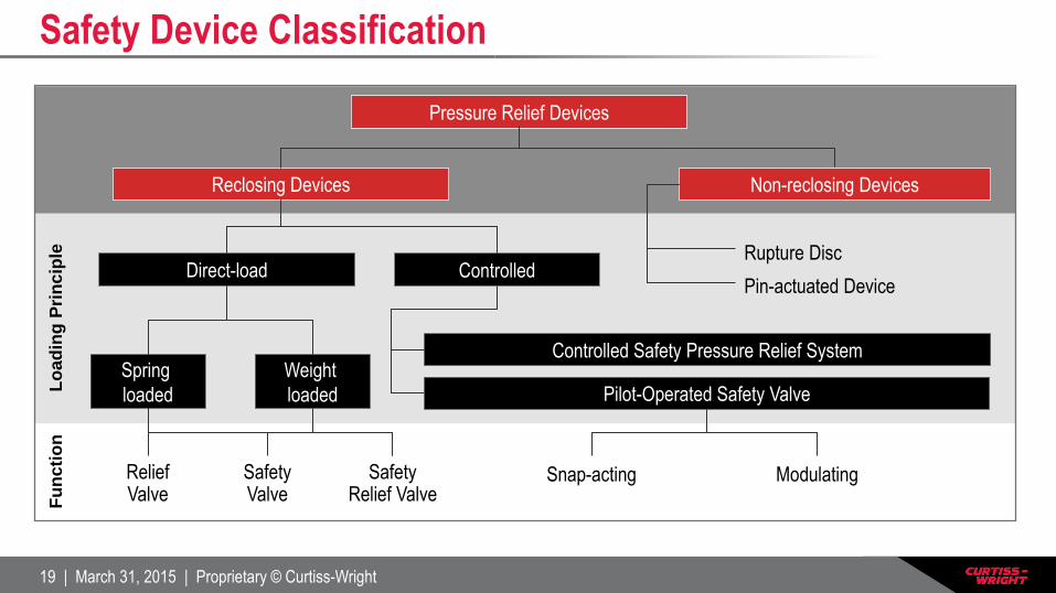
Pressure Relief Devices
Reclosing Devices Non-reclosing Devices
Direct-load Controlled
Controlled Safety Pressure Relief System Spring
loaded
Weight
loaded
Relief Valve
Safety Valve
Safety Relief Valve
Pilot-Operated Safety Valve
Snap-acting Modulating
Rupture Disc
Fu
ncti
on
L
oad
ing
Pri
nc
iple
Pin-actuated Device
Safety Device Classification
20 | March 31, 2015 | Proprietary © Curtiss-Wright
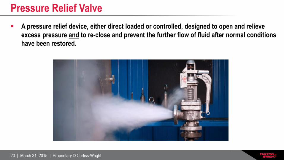
Pressure Relief Valve
A pressure relief device, either direct loaded or controlled, designed to open and relieve
excess pressure and to re-close and prevent the further flow of fluid after normal conditions
have been restored.

21 | March 31, 2015 | Proprietary © Curtiss-Wright
A pressure relief valve in which the opening and closing of the valve is controlled by a
spring.
Loading Principle: Spring Loaded
22 | March 31, 2015 | Proprietary © Curtiss-Wright
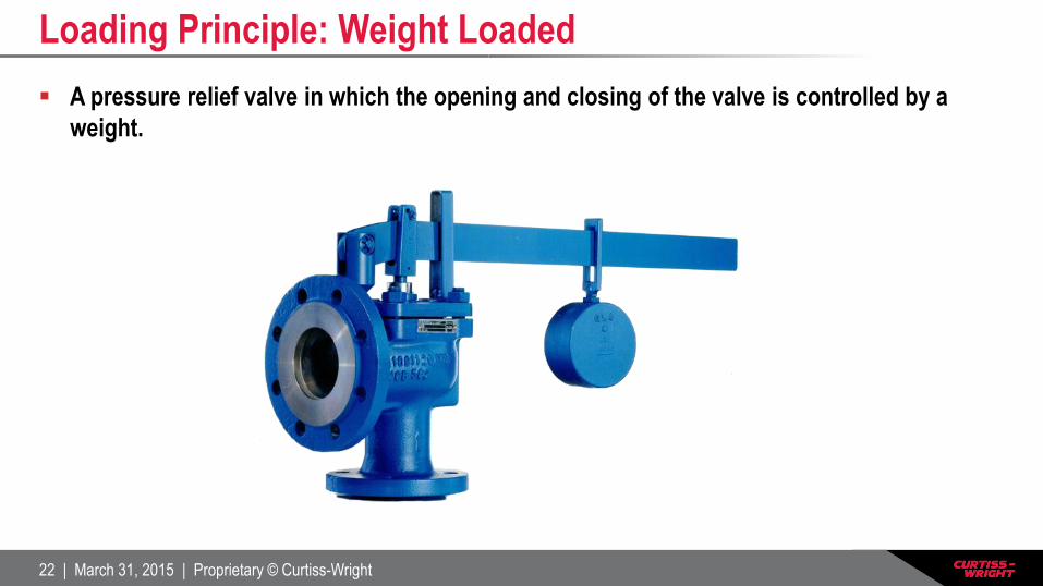
A pressure relief valve in which the opening and closing of the valve is controlled by a
weight.
Loading Principle: Weight Loaded
23 | March 31, 2015 | Proprietary © Curtiss-Wright
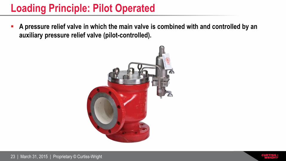
A pressure relief valve in which the main valve is combined with and controlled by an
auxiliary pressure relief valve (pilot-controlled).
Loading Principle: Pilot Operated
24 | March 31, 2015 | Proprietary © Curtiss-Wright
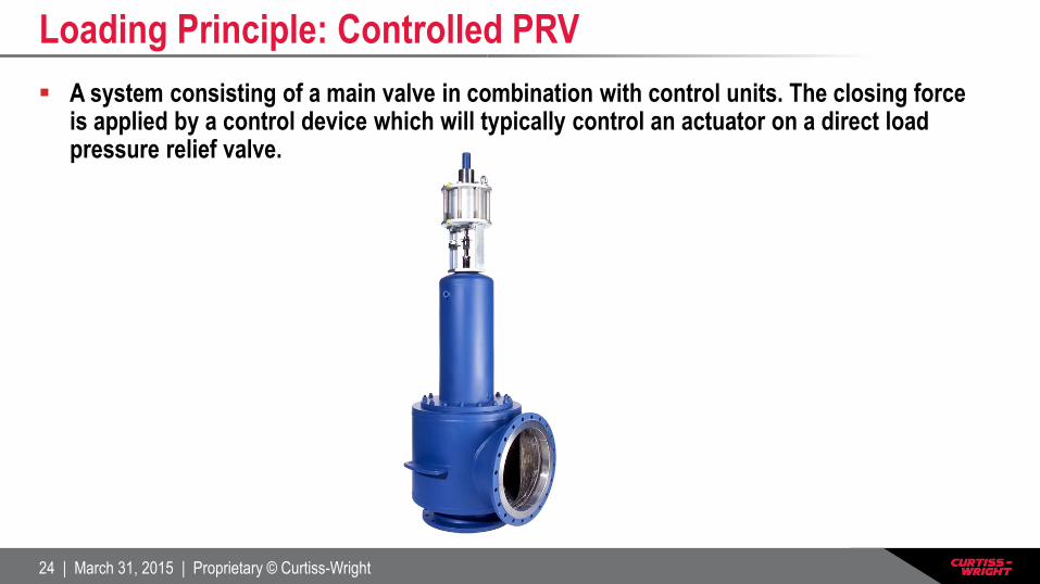
A system consisting of a main valve in combination with control units. The closing force is applied by a control device which will typically control an actuator on a direct load pressure relief valve.
Loading Principle: Controlled PRV
25 | March 31, 2015 | Proprietary © Curtiss-Wright
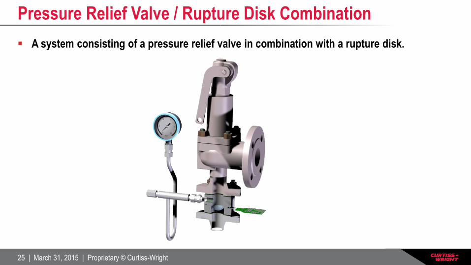
A system consisting of a pressure relief valve in combination with a rupture disk.
Pressure Relief Valve / Rupture Disk Combination

26 | March 31, 2015 | Proprietary © Curtiss-Wright
A spring loaded pressure relief valve which opens in proportion to the pressure
increase over the opening pressure. Used for liquid (non-compressible) service.
Relief Valve
p = set pressure ps = re-seat pressure
90 100 110
Lift [%]
Pressure [%]
100
80
60
40
20
0
p p s
27 | March 31, 2015 | Proprietary © Curtiss-Wright
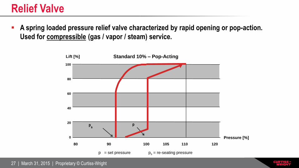
A spring loaded pressure relief valve characterized by rapid opening or pop-action.
Used for compressible (gas / vapor / steam) service.
Relief Valve
Standard 10% – Pop-Acting
p = set pressure ps = re-seating pressure
80 90 100 105 110 120
Lift [%]
Pressure [%]
100
80
60
40
20
0
p p s

28 | March 31, 2015 | Proprietary © Curtiss-Wright
A spring loaded pressure relief valve that may be used as either a safety or relief valve
depending on the application.
Pressure Relief Valve

29 | March 31, 2015 | Proprietary © Curtiss-Wright
The inlet gauge pressure at which the Pressure Relief Valve is set to open.
0
94 96 98 100 102 104 106 108 110 121
Lift (%)
Pressure (%)
Farris EU Competitors
Set to popping point
Set to initial audible discharge
Set Pressure

30 | March 31, 2015 | Proprietary © Curtiss-Wright
0
20
40
60
80
100
94 96 98 100 102 104 106 108 110 121
The audible or visible escape of compressible fluid between the seat and disc of the
Pressure Relief Valve prior to set pressure
Lift (%)
Pressure (%)
Simmer
Simmer

31 | March 31, 2015 | Proprietary © Curtiss-Wright
0
20
40
60
80
100
82 84 86 88 90 92 94 96 98100 102 104 106 108 110 121
The ratio of operating pressure to set pressure. 90% should not be exceeded for spring
loaded valves.
Lift (%)
Vessel
Pressure (%)
Op
erat
ing
Pre
ssu
re
Maximum Allowable
Working Pressure
Operating
Pressure
Ratio
Operating Pressure Ratio

32 | March 31, 2015 | Proprietary © Curtiss-Wright
0
20
40
60
80
100
76 78 80 82 84 86 88 90 92 94 98 100
The difference between the set pressure and the closing pressure of a Pressure Relief
Valve (expressed as a percentage of set pressure).
Lift (%)
Vessel Pressure (%)
Blow-
down
Blowdown
33 | March 31, 2015 | Proprietary © Curtiss-Wright
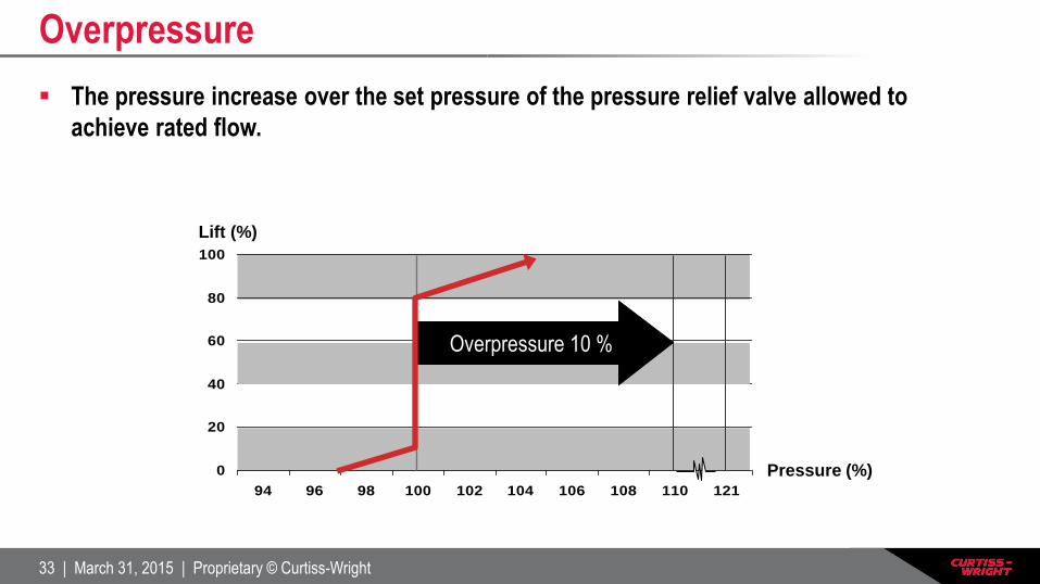
The pressure increase over the set pressure of the pressure relief valve allowed to
achieve rated flow.
Overpressure
0
20
40
60
80
100
94 96 98 100 102 104 106 108 110 121
Lift (%)
Pressure (%)
Overpressure 10 %
34 | March 31, 2015 | Proprietary © Curtiss-Wright
0
20
40
60
80
100
82 84 86 88 90 92 94 96 98100 102 104 106 108 110 121
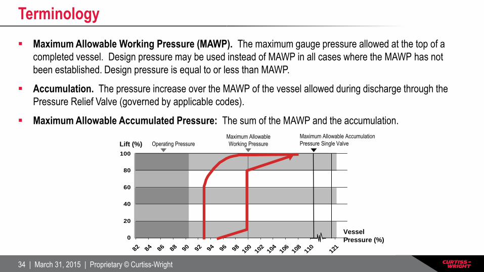
Maximum Allowable Working Pressure (MAWP). The maximum gauge pressure allowed at the top of a
completed vessel. Design pressure may be used instead of MAWP in all cases where the MAWP has not
been established. Design pressure is equal to or less than MAWP.
Accumulation. The pressure increase over the MAWP of the vessel allowed during discharge through the
Pressure Relief Valve (governed by applicable codes).
Maximum Allowable Accumulated Pressure: The sum of the MAWP and the accumulation.
Lift (%)
Vessel
Pressure (%)
Operating Pressure
Maximum Allowable
Working Pressure
Maximum Allowable Accumulation
Pressure Single Valve
Terminology
35 | March 31, 2015 | Proprietary © Curtiss-Wright
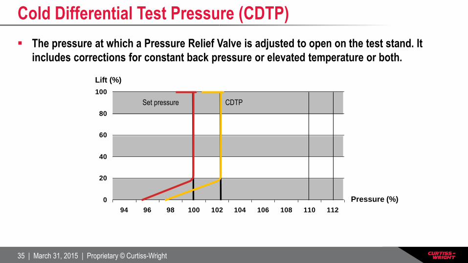
The pressure at which a Pressure Relief Valve is adjusted to open on the test stand. It
includes corrections for constant back pressure or elevated temperature or both.
Cold Differential Test Pressure (CDTP)
0
20
40
60
80
100
94 96 98 100 102 104 106 108 110 112
Lift (%)
Pressure (%)
Set pressure CDTP
36 | March 31, 2015 | Proprietary © Curtiss-Wright
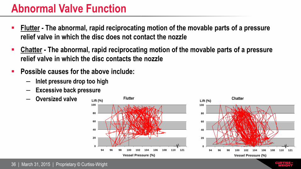
Flutter - The abnormal, rapid reciprocating motion of the movable parts of a pressure
relief valve in which the disc does not contact the nozzle
Chatter - The abnormal, rapid reciprocating motion of the movable parts of a pressure
relief valve in which the disc contacts the nozzle
Possible causes for the above include:
– Inlet pressure drop too high
– Excessive back pressure
– Oversized valve
Abnormal Valve Function
0
20
40
60
80
100
94 96 98 100 102 104 106 108 110 121
0
20
40
60
80
100
94 96 98 100 102 104 106 108 110 121
Lift (%)
Vessel Pressure (%)
Flutter Lift (%)
Vessel Pressure (%)
Chatter
37 | March 31, 2015 | Proprietary © Curtiss-Wright
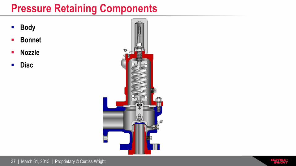
Body
Bonnet
Nozzle
Disc
Pressure Retaining Components

38 | March 31, 2015 | Proprietary © Curtiss-Wright
The area of contact between the valve nozzle and disc.
Valve Seat
39 | March 31, 2015 | Proprietary © Curtiss-Wright
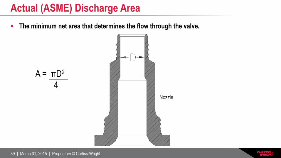
The minimum net area that determines the flow through the valve.
Actual (ASME) Discharge Area
A = πD2
4
Nozzle

40 | March 31, 2015 | Proprietary © Curtiss-Wright
Coefficient of Discharge (Kd)
The ratio of the mass flow rate in a valve to that of an ideal nozzle (used for calculating
flow through a Pressure Relief Valve).
– 9 tests are required for each valve series
– Average of the 9 tests shall be the coefficient of discharge (as long as each of the tests is ±5
% of the average).
– Cannot be greater than 0.975.
De-rated Coefficient of Discharge (K)
The product of the coefficient of discharge (Kd) and 0.9 (a 10 % de-rating factor
mandated by the ASME).
– The de-rated coefficient of discharge shall be used in all sizing calculations and capacity
calculations.
Coefficient of Discharge
41 | March 31, 2015 | Proprietary © Curtiss-Wright
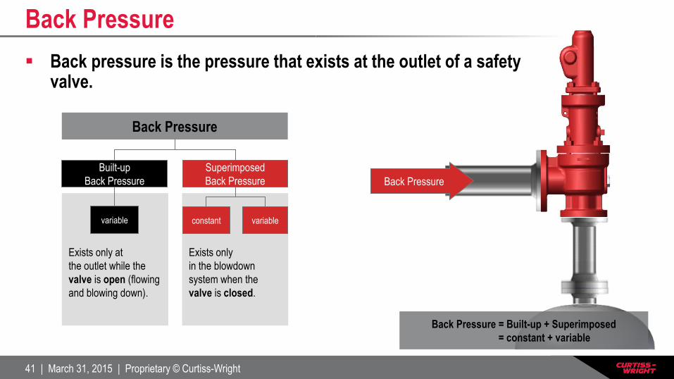
Exists only at
the outlet while the
valve is open (flowing
and blowing down).
Exists only
in the blowdown
system when the
valve is closed.
Back Pressure
Built-up
Back Pressure
Superimposed
Back Pressure
variable constant variable
Back pressure is the pressure that exists at the outlet of a safety valve.
Back Pressure
Back Pressure
Back Pressure = Built-up + Superimposed
= constant + variable
42 | March 31, 2015 | Proprietary © Curtiss-Wright
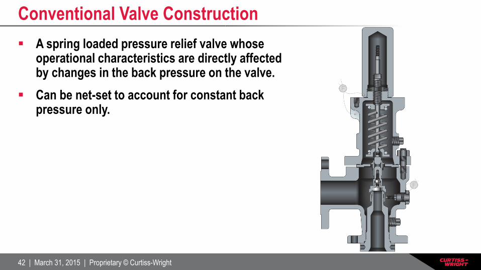
A spring loaded pressure relief valve whose operational characteristics are directly affected by changes in the back pressure on the valve.
Can be net-set to account for constant back pressure only.
Conventional Valve Construction

43 | March 31, 2015 | Proprietary © Curtiss-Wright
A spring loaded pressure relief valve that incorporates a bellows or other means to minimize the effect of back pressure on the operational characteristics of the valve.
Should be used when:
– The built-up back pressure to set pressure ratio exceeds
the allowable accumulation (or 10% as an industry rule).
– For isolating the bonnet chamber of the valve in
corrosive/hazardous service.
Balanced Bellows Valve Construction
44 | March 31, 2015 | Proprietary © Curtiss-Wright
Thank You
http://farris.cwfc.com
Farris Engineering
10195 Brecksville Road
Brecksville, OH 44141 USA