falcon 7x 02-70-05 ata 70 – engines codde 1 page 1 / 6 ...falcon 7x 02-70-05 codde 1 page 1 / 6...
TRANSCRIPT
FALCON 7X 02-70-05
CODDE 1 PAGE 1 / 6
DGT97831
ATA 70 – ENGINES GENERAL
ISSUE 2
DASSAULT AVIATION Proprietary Data
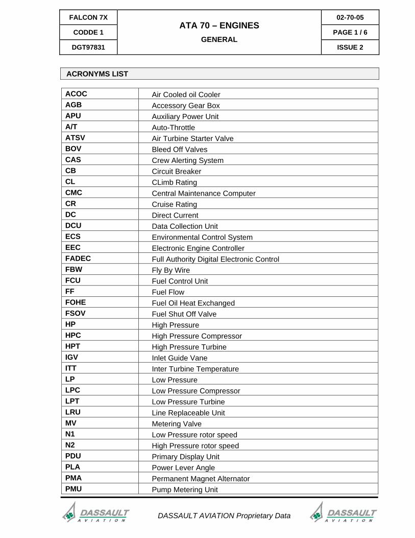
ACRONYMS LIST
ACOC Air Cooled oil CoolerAGB Accessory Gear BoxAPU Auxiliary Power UnitA/T Auto-ThrottleATSV Air Turbine Starter ValveBOV Bleed Off ValvesCAS Crew Alerting SystemCB Circuit BreakerCL CLimb RatingCMC Central Maintenance ComputerCR Cruise RatingDC Direct CurrentDCU Data Collection UnitECS Environmental Control SystemEEC Electronic Engine ControllerFADEC Full Authority Digital Electronic Control FBW Fly By WireFCU Fuel Control UnitFF Fuel FlowFOHE Fuel Oil Heat ExchangedFSOV Fuel Shut Off ValveHP High PressureHPC High Pressure CompressorHPT High Pressure TurbineIGV Inlet Guide VaneITT Inter Turbine TemperatureLP Low PressureLPC Low Pressure CompressorLPT Low Pressure TurbineLRU Line Replaceable UnitMV Metering ValveN1 Low Pressure rotor speedN2 High Pressure rotor speedPDU Primary Display UnitPLA Power Lever AnglePMA Permanent Magnet AlternatorPMU Pump Metering Unit
02-70-05 FALCON 7X
PAGE 2 / 6 CODDE 1
ISSUE 2
ATA 70 – ENGINES GENERAL
DGT97831
DASSAULT AVIATION Proprietary Data
RVDT Rotary Variable Differential TransformerSSPC Solid State Power controllerTLA Thrust Lever AngleT/R Thrust ReverserWOW Weight On Wheels
FALCON 7X 02-70-05
CODDE 1 PAGE 3 / 6
DGT97831
ATA 70 – ENGINES GENERAL
ISSUE 2
DASSAULT AVIATION Proprietary Data
INTRODUCTION
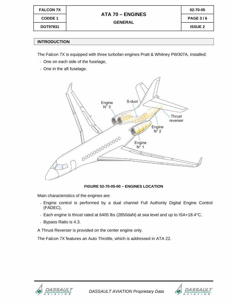
The Falcon 7X is equipped with three turbofan engines Pratt & Whitney PW307A, installed:
- One on each side of the fuselage,
- One in the aft fuselage.
FIGURE 02-70-05-00 – ENGINES LOCATION
Main characteristics of the engines are:
- Engine control is performed by a dual channel Full Authority Digital Engine Control (FADEC),
- Each engine is thrust rated at 6405 lbs (2850daN) at sea level and up to ISA+18.4°C,
- Bypass Ratio is 4.3.
A Thrust Reverser is provided on the center engine only.
The Falcon 7X features an Auto Throttle, which is addressed in ATA 22.
02-70-05 FALCON 7X
PAGE 4 / 6 CODDE 1
ISSUE 2
ATA 70 – ENGINES GENERAL
DGT97831
DASSAULT AVIATION Proprietary Data
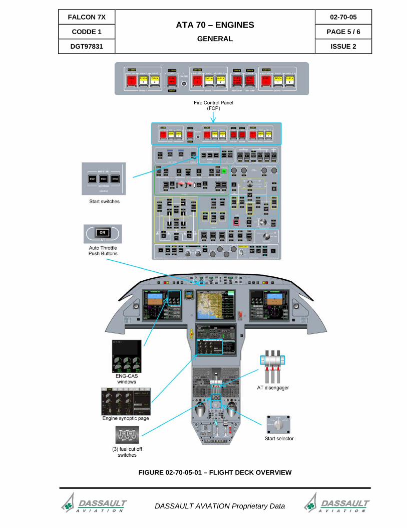
FLIGHT DECK OVERVIEW
CONTROLS
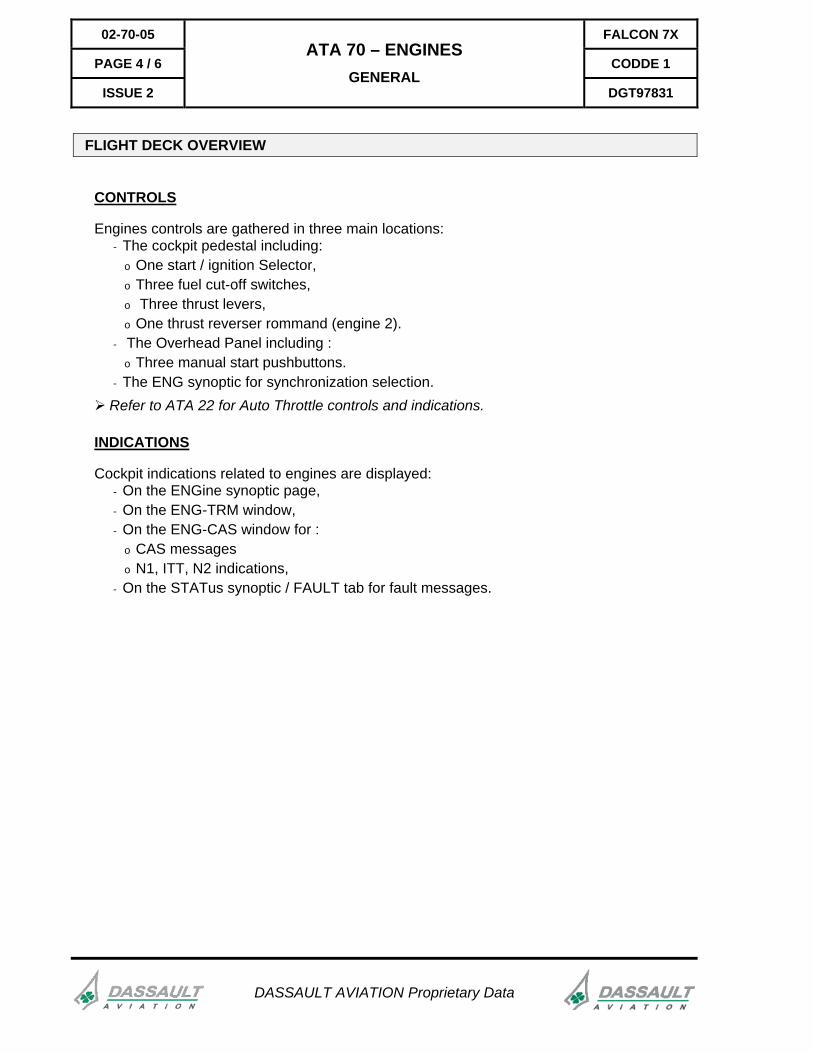
Engines controls are gathered in three main locations: - The cockpit pedestal including:
o One start / ignition Selector, o Three fuel cut-off switches, o Three thrust levers, o One thrust reverser rommand (engine 2).
- The Overhead Panel including : o Three manual start pushbuttons.
- The ENG synoptic for synchronization selection. Refer to ATA 22 for Auto Throttle controls and indications.
INDICATIONS
Cockpit indications related to engines are displayed: - On the ENGine synoptic page, - On the ENG-TRM window, - On the ENG-CAS window for :
o CAS messages o N1, ITT, N2 indications,
- On the STATus synoptic / FAULT tab for fault messages.
FALCON 7X 02-70-05
CODDE 1 PAGE 5 / 6
DGT97831
ATA 70 – ENGINES GENERAL
ISSUE 2
FIGURE 02-70-05-01 – FLIGHT DECK OVERVIEW
DASSAULT AVIATION Proprietary Data
FALCON 7X 02-70-10
CODDE 1 PAGE 1 / 8
DGT97831
ATA 70 – ENGINES DESCRIPTION
ISSUE 2
DASSAULT AVIATION Proprietary Data
INTRODUCTION
The PW307A is a turbofan engine with two spool type LP and HP compressor-turbine assemblies.
The Engine Control is performed by a FADEC (Full Authority Digital Engine Controller) based on dual channel Electronic Engine Controller (EEC), actuators and sensors.
The Engines provide:
- Thrust,
- Bleed air (for ECS and Anti ice),
- Mechanical energy to drive the hydraulic pumps,
- Mechanical energy to drive the DC generators and PMA.
Engine operation requires the following systems:
- Control system,
- Fuel system,
- Oil system,
- Ignition system,
- Air-start system.
02-70-10 FALCON 7X
PAGE 2 / 8 CODDE 1
ISSUE 2
ATA 70 – ENGINES DESCRIPTION
DGT97831
DASSAULT AVIATION Proprietary Data
ENGINE GENERAL DESCRIPTION
The PW307A is a turbofan engine with two spool type LP and HP compressor-turbine assemblies and one mixer nozzle. The LP compressor is the front single stage fan.
MAIN COMPONENTS
LP SPOOL
The LP spool main parts are: - A single stage fan compressor, - A multiple stage turbine.
HP SPOOL
The HP spool main parts are: - An axial compressor, - A centrifugal compressor, - A multiple stage turbine.
COMBUSTION SYSTEM
The combustor is a high efficiency, low volume design providing reduced emissions during all operating conditions. The fuel system consists of twenty-two fuel nozzles.
EXHAUST NOZZLE
Exhaust gases are mixed. The gas mixture provides lower external noise level.
ACCESSORY GEAR BOX (AGB)
The accessory gearbox is driven by the HP spool via the bevel gear:
Accessories driven by AGB are: - The pressure & scavenge oil pumps - The hydraulic pump(s), - The DC generator, - The hydro-mechanical Fuel Control Unit (FCU) - The Fly-By-Wire (FBW) PMA on engine 1 and 2. - FADEC PMA
Refer to DESCRIPTION - SUPPLEMENTARY INFORMATION section for additional information on engine components.
FALCON 7X 02-70-10
CODDE 1 PAGE 3 / 8
DGT97831
ATA 70 – ENGINES DESCRIPTION
ISSUE 2
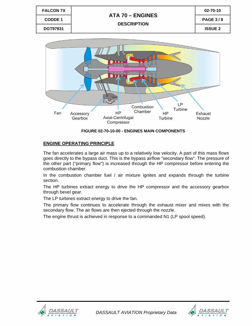
FIGURE 02-70-10-00 - ENGINES MAIN COMPONENTS
ENGINE OPERATING PRINCIPLE
The fan accelerates a large air mass up to a relatively low velocity. A part of this mass flows goes directly to the bypass duct. This is the bypass airflow "secondary flow". The pressure of the other part ("primary flow") is increased through the HP compressor before entering the combustion chamber. In the combustion chamber fuel / air mixture ignites and expands through the turbine section. The HP turbines extract energy to drive the HP compressor and the accessory gearbox through bevel gear. The LP turbines extract energy to drive the fan. The primary flow continues to accelerate through the exhaust mixer and mixes with the secondary flow. The air flows are then ejected through the nozzle. The engine thrust is achieved in response to a commanded N1 (LP spool speed).
DASSAULT AVIATION Proprietary Data
02-70-10 FALCON 7X
PAGE 4 / 8 CODDE 1
ISSUE 2
ATA 70 – ENGINES DESCRIPTION
DGT97831
DASSAULT AVIATION Proprietary Data
ENGINE SYSTEMS
ENGINE CONTROL
The engine is controlled by the FADEC. The FADEC is powered by the Permanent Magnetic Alternator (PMA) when engine is running. The FADEC performs the following main functions:
- Modulate the engine fuel flow to control engine N1 and N2 through acceleration, deceleration and steady state operation,
- Schedule and control the surge protection systems - Protect from N1 / N2 overspeed and ITT overtemperature, - Control start / ignition sequence and Air Turbine Starter Valve (ATSV).
Engine synchronization is activated upon crew selection. The "synchronization" function: - Synchronizes the three engines N1 or N2 (from IDLE to MAX CLIMB) - Using engine 2 as the master, - Engines 1 and 3 settings are "slaved" to engine 2 setting.
FUEL SYSTEM
- Fuel supply is provided from the airplane fuel system via the fuel shut off valve.
OIL SYSTEM
- Each engine has a self-contained oil system that supplies oil to cool and lubricate the engine bearings (LP and HP rotors bearings and AGB).
IGNITION SYSTEM
Each engine is supplied with a dual ignition system operated by: - The FADEC in auto mode, - The start selector for continuous ignition, - The avionics system in case of stall warning condition.
The ignition system is powered by the airplane electrical system.
FALCON 7X 02-70-10
CODDE 1 PAGE 5 / 8
DGT97831
ATA 70 – ENGINES DESCRIPTION
ISSUE 2
DASSAULT AVIATION Proprietary Data
STARTING SYSTEM
The engine is fitted with an air turbine starter requiring bleed air from: - The APU, - Ground air cart, - An other engine in cross bleed start.
During starting phase, the FADEC provides: - An automatic starting sequencing of the igniters and the ATSV, - Control of fuel flow, - Protection of engine (exceeding parameters).
The Starter system is powered by the airplane electrical system.
FIRE PROTECTION
Refer to ATA 26 - FIRE PROTECTION for additional information.
THRUST REVERSER SYSTEM
A thrust reverser system is installed on No 2 engine. It is designed for ground operation only. The thrust reverser system consists of:
- Two (partial fish mouth) thrust reverser doors, - Two hydraulic actuators.
The thrust reverser is powered by: - Hydraulic B system, - An accumulator (one extention and one retraction in case of Hydraulic system B
inoperative). Thrust reverser is available when:
- Main landing gears are compressed, - Engine thrust lever 2 in IDLE position.
Refer to DESCRIPTION - SUPPLEMENTARY INFORMATION section for additional information on engine systems.
02-70-10 FALCON 7X
PAGE 6 / 8 CODDE 1
ISSUE 2
ATA 70 – ENGINES DESCRIPTION
DGT97831
DASSAULT AVIATION Proprietary Data
OPERATION - ENGINE START AND MOTORING PRINCIPLE
GENERAL
There are four distinct modes of engine starting: - Ground start, - In flight starter assisted relight, - In flight windmilling relight, - In flight auto relight (flame out detected by FADEC).
There are two modes of motoring: - Dry motoring, - Wet motoring.
The FADEC provides: - Automatic starting sequencing of the igniters and start valve, - Control of fuel flow, - Protection of engine (protection against parameters exceeding).
ENGINE START
GROUND START
Ground start is initiated by the pilot by selecting START on the start selector with: - Airplane on ground (WOW signal), - N2 less than 50%, - Start selector in NORMAL position, - Fuel Cut Off switch in "ON" position.
After the start selector is selected on START: - Signals are sent to airplane systems in order to:
o Isolate bleed air supply to the ECS, o Depressurize hydraulic pumps to unload the starter,
- The ATSV is commanded open after a 5 seconds delay , - The pneumatic starter drives the HP spool, - The pneumatic starter stops operating when the engine reaches 50% N2 (ATSV
closed) During the sequence, the FADEC:
- Commands fuel flow and ignition as N2 increases, - Interrupts starting sequence when abnormal conditions are detected.
Refer to SYSTEM PROTECTIONS – ACTIVE PROTECTIONS section.
FALCON 7X 02-70-10
CODDE 1 PAGE 7 / 8
DGT97831
ATA 70 – ENGINES DESCRIPTION
ISSUE 2
DASSAULT AVIATION Proprietary Data
IN FLIGHT STARTER ASSISTED RELIGHT
The air pressure will be provided by another engine (cross bleed start).
The airplane must be within the starter assist relight envelope (speed and altitude).
The starter sequence is similar to ground start but through the MAN START pushbutton of the overhead panel
IN FLIGHT WINDMILLING RELIGHT
Without starter assist, the airplane must be within the windmilling relight envelope (speed and altitude).
Thus, established ram air flow provides sufficient pressure ratio for a successful relight.
Ignition and fuel are provided with fuel switch ON and MAN START pushbutton on IGN or NORM position.
IN FLIGHT AUTO RELIGHT
The flame out condition is detected by the FADEC.
The ignition will automatically be sequenced ON for both igniters immediately upon flame out detection.
ENGINE MOTORING
DRY MOTORING ON GROUND
A dry motoring is performed to evacuate residual fuel or vapors and to reduce ITT before attempting a new start sequence.
WET MOTORING ON GROUND
A wet motoring is performed for maintenance purposes.
Refer to CODDE 2 for procedures related to engine start or motoring.
FALCON 7X 02-70-15
CODDE 1 PAGE 1 / 12
DGT97831
ATA 70 – ENGINES DESCRIPTION - SUPPLEMENTARY INFORMATION
ISSUE 2
DASSAULT AVIATION Proprietary Data
DESIGN PRINCIPLES
The engine was designed considering the following design principles:
- With regard to reliability:
o Redundancy of the control system is provided with two independant EEC channel controlling all functions,
o Each FADEC is powered by its PMA and aircraft DC power,
o The power supply distribution allows restart in case of triple engine flame out,
o Protections are provided against surge, flame out, overspeed and overtemperature.
- With regard to fuel consumption and take-off performances:
o High bypass ratio design (4.3):
o High efficiency combustion chamber and nozzles design,
o Mixing of primary and secondary flow at exhaust,
o Full Authority Digital Engine Control
- With regard to pilot workload:
o Automatic engines command, control, and monitoring.
- With regard to environmental protection:
o Noise reduction with:
� Acoustic treatments (inlet inner barrel, aft fan duct, S-duct)
� Mixing of primary and secondary flow at exhaust
o Reduced gas emission at all operating conditions with:
� Combustion chamber and nozzles designed with high efficiency.
- With regard to maintenance:
o Engine data recording on DCU for trouble shooting, trend monitoring, cycles follow up.
02-70-15 FALCON 7X
PAGE 2 / 12 CODDE 1
ISSUE 2
ATA 70 – ENGINES DESCRIPTION - SUPPLEMENTARY INFORMATION
DGT97831
DASSAULT AVIATION Proprietary Data
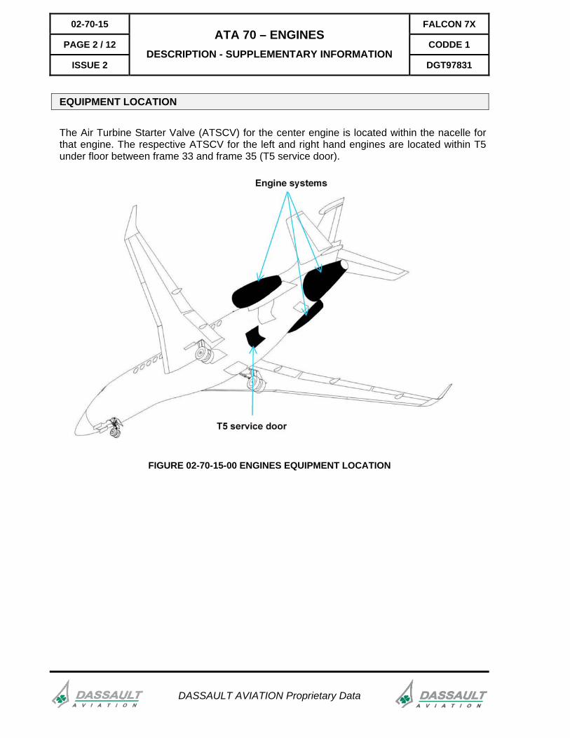
EQUIPMENT LOCATION
The Air Turbine Starter Valve (ATSCV) for the center engine is located within the nacelle for that engine. The respective ATSCV for the left and right hand engines are located within T5 under floor between frame 33 and frame 35 (T5 service door).
FIGURE 02-70-15-00 ENGINES EQUIPMENT LOCATION
FALCON 7X 02-70-15
CODDE 1 PAGE 3 / 12
DGT97831
ATA 70 – ENGINES DESCRIPTION - SUPPLEMENTARY INFORMATION
ISSUE 2
DASSAULT AVIATION Proprietary Data
ELECTRICAL POWER SUPPLY
Following paragraph describes the power supply of the different equipment of the engine system.
Electrical protection is provided either:
- By Solid State Power Controller (SSPC)
- By Circuit Breakers (CB)
Refer to ATA 24 ELECTRICAL POWER for additional information
EQUIPMENT POWER SUPPLY TYPE OF PROTECTIONFADEC / EEC ENG 1
Chanel A
LH ESS
PMA (Engine running)SSPC
FADEC / EEC ENG 1
Chanel B
RH MAIN
PMA (engine running)CB
FADEC / EEC ENG 2
Chanel A
RH ESS
PMA (engine running)SSPC
FADEC / EEC ENG 2
Chanel B
LH MAIN
PMA (Engine running)SSPC
FADEC / EEC ENG 3
Chanel A
LH ESS
PMA (Engine running)SSPC
FADEC / EEC ENG3
Chanel B
RH MAIN
PMA (Engine running)CB
IGN ENG 1 Chanel A LH ESS SSPC
IGN ENG 1 Chanel B RH MAIN CB
IGN ENG 2 Chanel A RH ESS SSPC
IGN ENG 2 Chanel B LH MAIN CB
IGN ENG 3 Chanel A LH ESS SSPC
IGN ENG 3 Chanel B RH MAIN CB
Thrust /reverser system LH MAIN CB
02-70-15 FALCON 7X
PAGE 4 / 12 CODDE 1
ISSUE 2
ATA 70 – ENGINES DESCRIPTION - SUPPLEMENTARY INFORMATION
DGT97831
DASSAULT AVIATION Proprietary Data
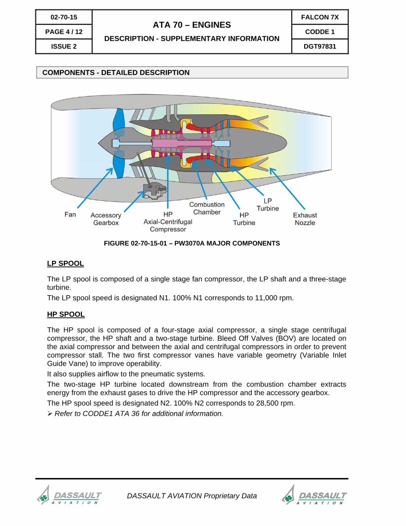
COMPONENTS - DETAILED DESCRIPTION
FIGURE 02-70-15-01 – PW3070A MAJOR COMPONENTS
LP SPOOL
The LP spool is composed of a single stage fan compressor, the LP shaft and a three-stage turbine. The LP spool speed is designated N1. 100% N1 corresponds to 11,000 rpm.
HP SPOOL
The HP spool is composed of a four-stage axial compressor, a single stage centrifugal compressor, the HP shaft and a two-stage turbine. Bleed Off Valves (BOV) are located on the axial compressor and between the axial and centrifugal compressors in order to prevent compressor stall. The two first compressor vanes have variable geometry (Variable Inlet Guide Vane) to improve operability. It also supplies airflow to the pneumatic systems. The two-stage HP turbine located downstream from the combustion chamber extracts energy from the exhaust gases to drive the HP compressor and the accessory gearbox. The HP spool speed is designated N2. 100% N2 corresponds to 28,500 rpm.
Refer to CODDE1 ATA 36 for additional information.
FALCON 7X 02-70-15
CODDE 1 PAGE 5 / 12
DGT97831
ATA 70 – ENGINES DESCRIPTION - SUPPLEMENTARY INFORMATION
ISSUE 2
DASSAULT AVIATION Proprietary Data
COMBUSTION SYSTEM
The combustor is a high efficiency, low volume design providing reduced emissions at all operating conditions. The sheet metal and machined ring construction incorporates floating wall heat shields to provide increased durability and ease of maintenance. The fuel system consists of twenty-two pure air blast fuel nozzles which deliver the fuel to the combustor providing excellent atomization and enhanced mixing with combustion air. Ignition is achieved by two igniters, aligned with two primary fuel nozzles, to guarantee starting and relight in the declared envelops.
EXHAUST NOZZLE
Exhaust gases, exiting the LP turbine, are directed through the mixer. The mixer forces high speed exhaust gases to mix with the fan peripheral secondary airflow. The gas mixture provides higher thrust and lower external noise level.
ACCESSORY GEAR BOX (AGB)
The accessory gearbox is driven by the HP spool through the bevel gear. All engine-driven accessories, except N1 LP rotor speed sensor, are on the accessory gearbox which transmits the mechanical power necessary for:
- The oil pump, - The hydraulic pump(s), - The DC generator, - The Hydro-mechanical Fuel Control Unit (FCU) which controls fuel flow and the angle of
HP compressor inlet guide vanes, - The Permanent Magnetic Alternator (PMA), which provides power to the Full Authority
Digital Electronic Control (FADEC), - The Fly-By-Wire PMA on engines 1 and 2.
02-70-15 FALCON 7X
PAGE 6 / 12 CODDE 1
ISSUE 2
ATA 70 – ENGINES DESCRIPTION - SUPPLEMENTARY INFORMATION
DGT97831
DASSAULT AVIATION Proprietary Data
ENGINE SYSTEMS
ENGINE CONTROL
The engines are electro-mechanically controlled by Full Authority Digital Engine Control (FADEC). The computer of the FADEC is the Electronic Engine Control (EEC). The FADEC is powered by both the airplane electrical system and the independent Permanent Magnetic Alternator (PMA). There is one FADEC per engine and each FADEC has two channels. Both channels run, but only one is in control at a time. During the start-up sequence, channels are alternatively swapped, allowing the test of the stand-by channel. The FADEC continuously performs self-check and cross-check of both channels. In case of discrepancy between the two channels, the faulty one is automatically inhibited. Loss of both channels of a FADEC leads to respective engine shutdown. The FADEC performs:
- Complete engine start control, - Opening of the bleed-off valves when necessary, - Engine N1 and N2 control through acceleration, deceleration and steady state
operation, - Synchronization of Lateral engines speed on Center one (operates on N1 or N2 on
request by crew), - Ignition control, - Variable inlet guide vanes control, - Supply engine parameters to avionics (N1, N2, ITT, oil temperature and pressure,...), - Thrust reverser control and monitoring, - Automatic engine relight.
It also protects the engine against damage by ensuring: - Start protection, - Temperature monitoring, - Overspeed protection, - Monitoring of N2 to avoid spool-down and automatic engine relight (on stall or flameout
detection).
FALCON 7X 02-70-15
CODDE 1 PAGE 7 / 12
DGT97831
ATA 70 – ENGINES DESCRIPTION - SUPPLEMENTARY INFORMATION
ISSUE 2
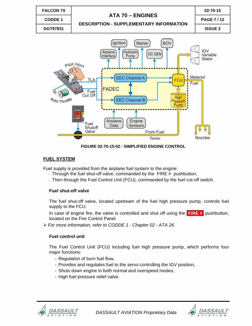
FIGURE 02-70-15-02 - SIMPLIFIED ENGINE CONTROL
FUEL SYSTEM
Fuel supply is provided from the airplane fuel system to the engine: - Through the fuel shut-off valve, commanded by the FIRE # pushbutton, - Then through the Fuel Control Unit (FCU), commanded by the fuel cut-off switch.
Fuel shut-off valve
The fuel shut-off valve, located upstream of the fuel high pressure pump, controls fuel supply to the FCU. In case of engine fire, the valve is controlled and shut off using the FIRE # pushbutton, located on the Fire Control Panel.
For more information, refer to CODDE 1 - Chapter 02 - ATA 26.
Fuel control unit
The Fuel Control Unit (FCU) including fuel high pressure pump, which performs four major functions:
- Regulation of burn fuel flow, - Provides and regulates fuel to the servo controlling the IGV position, - Shuts down engine in both normal and overspeed modes, - High fuel pressure relief valve.
DASSAULT AVIATION Proprietary Data
02-70-15 FALCON 7X
PAGE 8 / 12 CODDE 1
ISSUE 2
ATA 70 – ENGINES DESCRIPTION - SUPPLEMENTARY INFORMATION
DGT97831
DASSAULT AVIATION Proprietary Data
High pressure fuel pump
The high pressure fuel pump is made of two stages and feeds the fuel flow divider with fuel at the required pressure and flow rate. The first stage is a centrifugal booster pump, and the second one is a gear pump. There is a fuel filter between the two pump stages. A part of the fuel is by-passed after the second stage through the Fuel-Oil Heat Exchanger (FOHE) to increase its temperature and is then directed to the filter again to prevent it from being clogged by ice.
The filter is fitted with a by-pass valve. When the filter is clogged, the by-pass valve opens and activates the ENG .. FUEL FILT BYPASS Fault message.
Fuel control unit
The fuel control unit also includes a fuel-metering valve, a guide vanes valve and an overspeed protection solenoid. The whole FCU is protected from overpressure by a high pressure relief valve. This valve opens if the outlet pressure of the second stage is higher than 1,500 psi bypassing the second stage.
Fuel flow divider
The fuel flow divider improves combustion performance during the start sequence by optimizing fuel distribution close to igniters.
Distribution system
The distribution system includes 22 fuel nozzles (18 secondary nozzles and 4 primary nozzles).

FALCON 7X 02-70-15
CODDE 1 PAGE 9 / 12
DGT97831
ATA 70 – ENGINES DESCRIPTION - SUPPLEMENTARY INFORMATION
ISSUE 2
DASSAULT AVIATION Proprietary Data
OIL SYSTEM
Each engine has a self-contained oil system that supplies oil to cool and lubricate the engine bearings. The oil tank has a maximum capacity of 2.08 US gallons. The minimum tank quantity allowable without adversely affecting the operation of the engine is 1.25 US gallons (4.73 liters). At maximum oil consumption, the engine will have sufficient oil for at least 30 hours running from the maximum level. With the oil system at minimum servicing level, the engine will be capable of one maximum range flight at the maximum specified oil consumption. The oil system provides the HP and LP spools bearings and the accessory gearbox with lubrication and cooling. It mainly features:
- A pressurized oil tank with a sight glass and electric gauge, - A pressure pump flow-regulating to feed the system from the oil tank, - A clogging filter located downstream from oil pressure pump, - A Fuel-Oil Heat Exchanger (FOHE) which cools oil and heat fuel, - Air Cooled Oil Cooler (ACOC) which cools oil. - A combination of scavenge pumps to feed back the oil tank directly or via the accessory
gearbox and separate the air from the oil, both mixed in the engine, - A chip detector located upstream of oil tank, - Temperature and pressure probes and a low pressure switch.
The electrical gauge supplies oil quantity data to the avionics.
NOTE
Oil quantity should be checked 10 min after engine shutdown, and serviced with the type and brand specified in the CODDE 2.
The oil filter is equipped with by-pass line and a switch, which transmits the filter clogging information. When the filter is clogged, prior to the bypass opening, the ENG ..: OIL FILTER message appears in the status page. The chip detector plug attracts ferrous metal and detects significant accumulation of particles. When ferrous metal particles accumulate on the chip detector, the related ENG ..: OIL CHIP message appears in the status page. Engine oil temperature is measured just upstream from the engine bearings. Indicated engine oil pressure corresponds to the differential pressure measured upstream and downstream engine bearings in one of the scavenge lines. A separate differential sensor is dedicated to low oil pressure warning and triggers the ENG .. OIL TOO LO PRESS message when pressure is below 10 psi or below 20 psi for more than 3’ Oil pressure is not regulated at a steady value and will vary following engine N2.
02-70-15 FALCON 7X
PAGE 10 / 12 CODDE 1
ISSUE 2
ATA 70 – ENGINES DESCRIPTION - SUPPLEMENTARY INFORMATION
DGT97831
DASSAULT AVIATION Proprietary Data
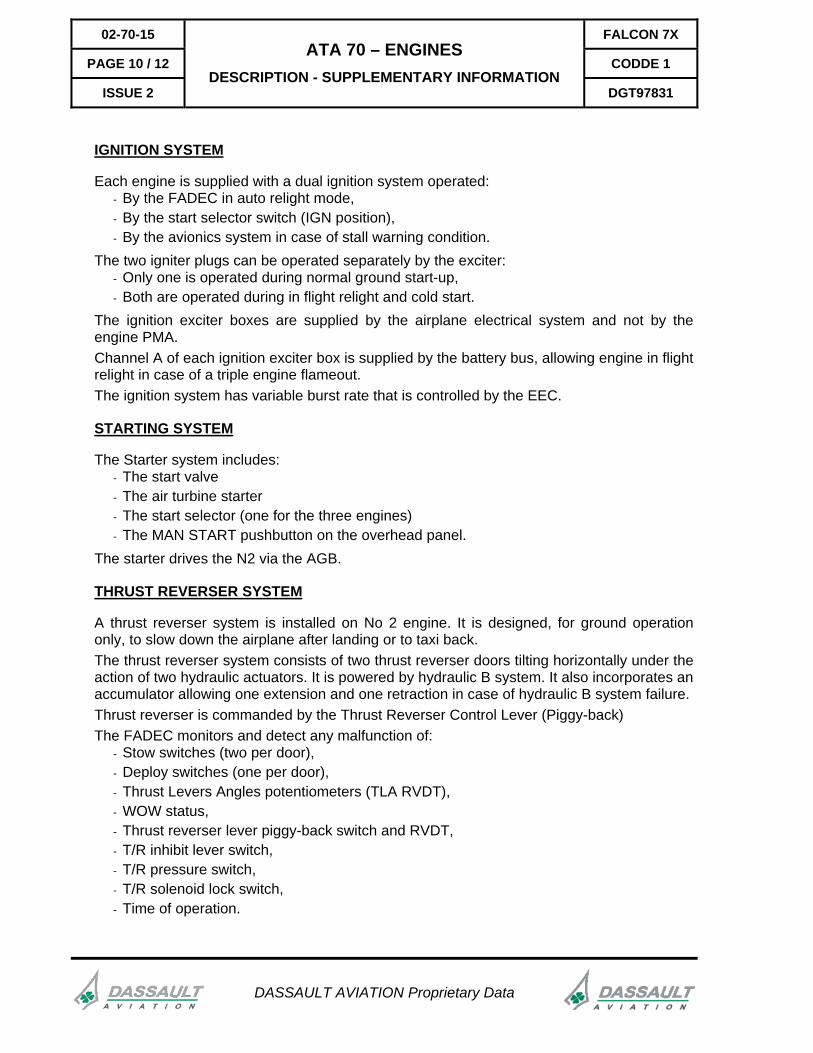
IGNITION SYSTEM
Each engine is supplied with a dual ignition system operated: - By the FADEC in auto relight mode, - By the start selector switch (IGN position), - By the avionics system in case of stall warning condition.
The two igniter plugs can be operated separately by the exciter: - Only one is operated during normal ground start-up, - Both are operated during in flight relight and cold start.
The ignition exciter boxes are supplied by the airplane electrical system and not by the engine PMA. Channel A of each ignition exciter box is supplied by the battery bus, allowing engine in flight relight in case of a triple engine flameout. The ignition system has variable burst rate that is controlled by the EEC.
STARTING SYSTEM
The Starter system includes: - The start valve - The air turbine starter - The start selector (one for the three engines) - The MAN START pushbutton on the overhead panel.
The starter drives the N2 via the AGB.
THRUST REVERSER SYSTEM
A thrust reverser system is installed on No 2 engine. It is designed, for ground operation only, to slow down the airplane after landing or to taxi back. The thrust reverser system consists of two thrust reverser doors tilting horizontally under the action of two hydraulic actuators. It is powered by hydraulic B system. It also incorporates an accumulator allowing one extension and one retraction in case of hydraulic B system failure. Thrust reverser is commanded by the Thrust Reverser Control Lever (Piggy-back) The FADEC monitors and detect any malfunction of:
- Stow switches (two per door), - Deploy switches (one per door), - Thrust Levers Angles potentiometers (TLA RVDT), - WOW status, - Thrust reverser lever piggy-back switch and RVDT, - T/R inhibit lever switch, - T/R pressure switch, - T/R solenoid lock switch, - Time of operation.
FALCON 7X 02-70-15
CODDE 1 PAGE 11 / 12
DGT97831
ATA 70 – ENGINES DESCRIPTION - SUPPLEMENTARY INFORMATION
ISSUE 2
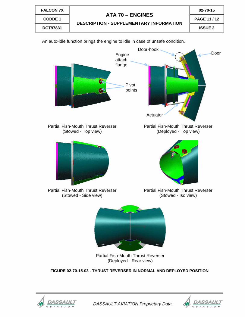
An auto-idle function brings the engine to idle in case of unsafe condition.
Partial Fish-Mouth Thrust Reverser
(Stowed - Top view) Partial Fish-Mouth Thrust Reverser
(Deployed - Top view)
Partial Fish-Mouth Thrust Reverser
(Stowed - Side view) Partial Fish-Mouth Thrust Reverser
(Stowed - Iso view)
Partial Fish-Mouth Thrust Reverser
(Deployed - Rear view)
Pivot points
Door-hook
Actuator
Engine attach flange
Door
FIGURE 02-70-15-03 - THRUST REVERSER IN NORMAL AND DEPLOYED POSITION
DASSAULT AVIATION Proprietary Data
FALCON 7X 02-70-20
CODDE 1 PAGE 1 / 16
DGT97831
ATA 70 – ENGINES CONTROLS AND INDICATIONS
ISSUE 2
DASSAULT AVIATION Proprietary Data
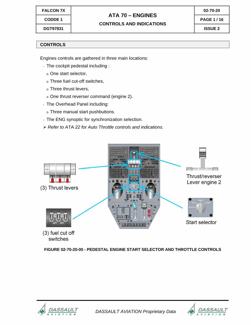
CONTROLS
Engines controls are gathered in three main locations:
- The cockpit pedestal including :
o One start selector,
o Three fuel cut-off switches,
o Three thrust levers,
o One thrust reverser command (engine 2).
- The Overhead Panel including:
o Three manual start pushbuttons.
- The ENG synoptic for synchronization selection.
Refer to ATA 22 for Auto Throttle controls and indications.
FIGURE 02-70-20-00 - PEDESTAL ENGINE START SELECTOR AND THROTTLE CONTROLS
02-70-20 FALCON 7X
PAGE 2 / 16 CODDE 1
ISSUE 2
ATA 70 – ENGINES CONTROLS AND INDICATIONS
DGT97831
DASSAULT AVIATION Proprietary Data
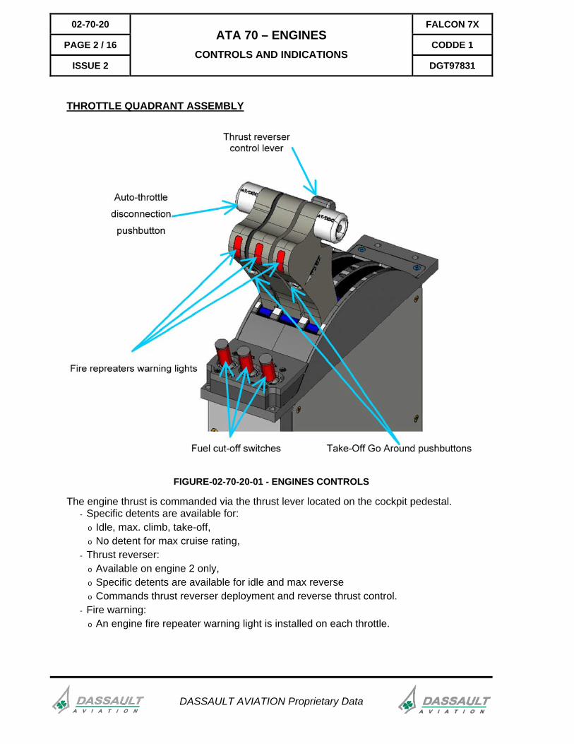
THROTTLE QUADRANT ASSEMBLY
FIGURE-02-70-20-01 - ENGINES CONTROLS
The engine thrust is commanded via the thrust lever located on the cockpit pedestal. - Specific detents are available for:
o Idle, max. climb, take-off, o No detent for max cruise rating,
- Thrust reverser: o Available on engine 2 only, o Specific detents are available for idle and max reverse o Commands thrust reverser deployment and reverse thrust control.
- Fire warning: o An engine fire repeater warning light is installed on each throttle.
FALCON 7X 02-70-20
CODDE 1 PAGE 3 / 16
DGT97831
ATA 70 – ENGINES CONTROLS AND INDICATIONS
ISSUE 2
NOTE
Engines 1 & 3 thrust levers are fitted with auto-throttle disengagement pushbutton (refer to ATA 22)
FUEL CUT-OFF SWITCH
Three fuel cut-off switches (one per engine) are located on the pedestal. They have two positions: Fuel ON / Fuel OFF.
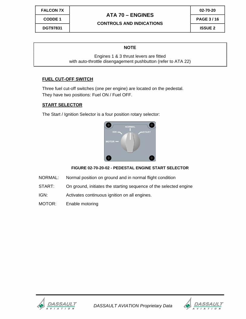
START SELECTOR
The Start / Ignition Selector is a four position rotary selector:
FIGURE 02-70-20-02 - PEDESTAL ENGINE START SELECTOR
NORMAL: Normal position on ground and in normal flight condition
START: On ground, initiates the starting sequence of the selected engine
IGN: Activates continuous ignition on all engines.
MOTOR: Enable motoring
DASSAULT AVIATION Proprietary Data
02-70-20 FALCON 7X
PAGE 4 / 16 CODDE 1
ISSUE 2
ATA 70 – ENGINES CONTROLS AND INDICATIONS
DGT97831
DASSAULT AVIATION Proprietary Data
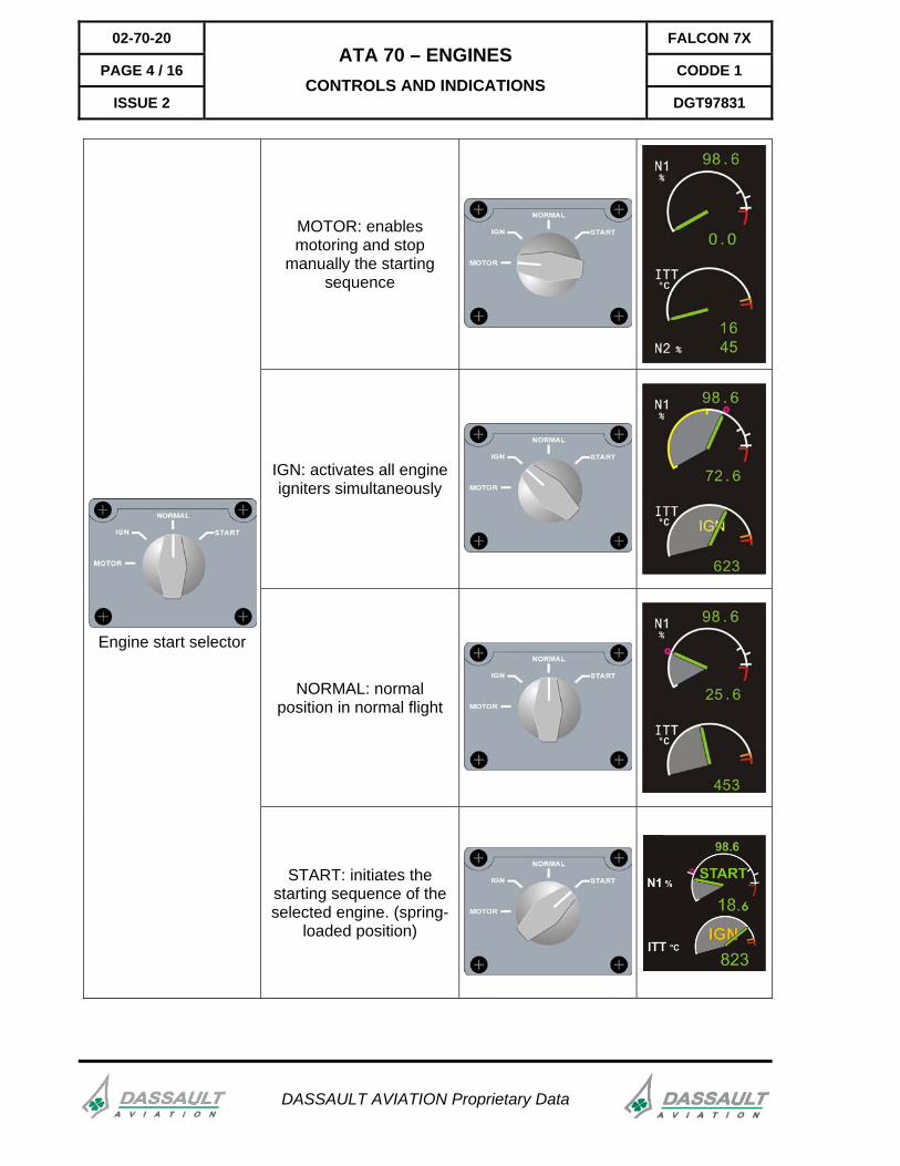
MOTOR: enables motoring and stop
manually the starting sequence
IGN: activates all engine igniters simultaneously
NORMAL: normal position in normal flight
Engine start selector
START: initiates the starting sequence of the selected engine. (spring-
loaded position)
FALCON 7X 02-70-20
CODDE 1 PAGE 5 / 16
DGT97831
ATA 70 – ENGINES CONTROLS AND INDICATIONS
ISSUE 2
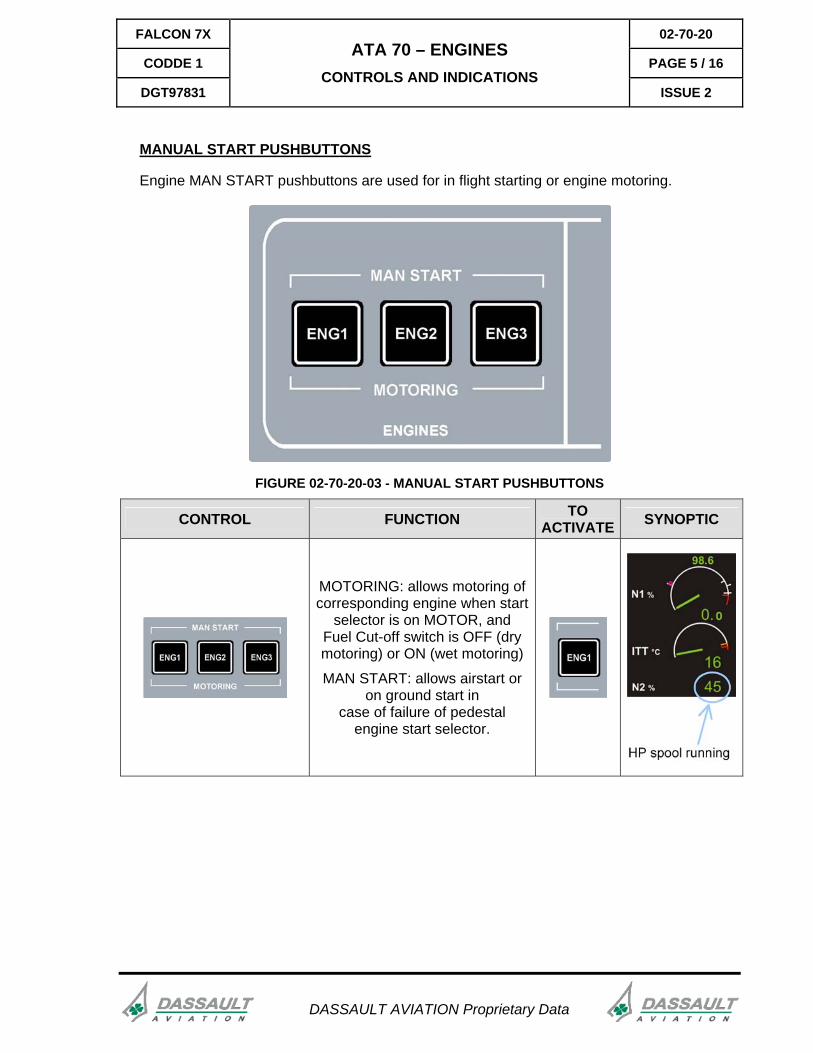
MANUAL START PUSHBUTTONS
Engine MAN START pushbuttons are used for in flight starting or engine motoring.
FIGURE 02-70-20-03 - MANUAL START PUSHBUTTONS
CONTROL FUNCTION TO ACTIVATE SYNOPTIC
MOTORING: allows motoring of corresponding engine when start
selector is on MOTOR, and Fuel Cut-off switch is OFF (dry motoring) or ON (wet motoring)
MAN START: allows airstart or on ground start in
case of failure of pedestal engine start selector.
DASSAULT AVIATION Proprietary Data
02-70-20 FALCON 7X
PAGE 6 / 16 CODDE 1
ISSUE 2
ATA 70 – ENGINES CONTROLS AND INDICATIONS
DGT97831
DASSAULT AVIATION Proprietary Data
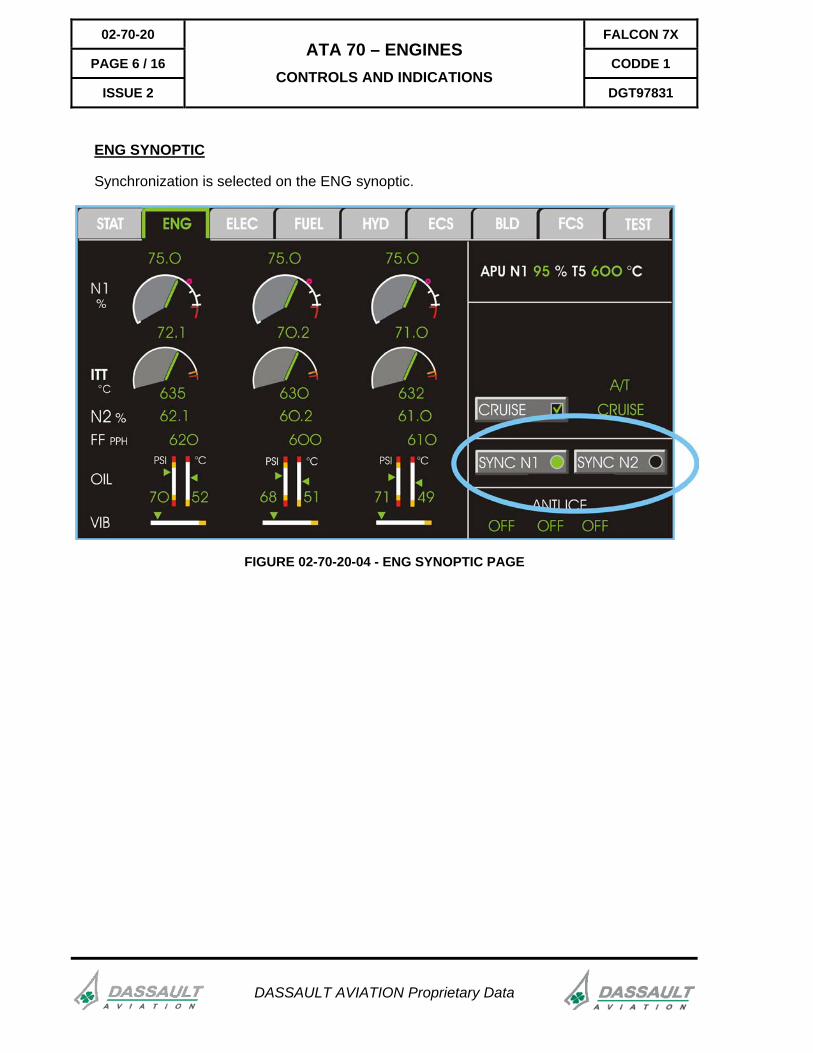
ENG SYNOPTIC
Synchronization is selected on the ENG synoptic.
FIGURE 02-70-20-04 - ENG SYNOPTIC PAGE

FALCON 7X 02-70-20
CODDE 1 PAGE 7 / 16
DGT97831
ATA 70 – ENGINES CONTROLS AND INDICATIONS
ISSUE 2
DASSAULT AVIATION Proprietary Data
INDICATIONS
Cockpit indications related to engines are displayed:
- On the ENGine Synoptic Page,
- On the ENG-CAS window for CAS messages, N1, ITT, and N2 indications,
- On the ENG-TRM window for fuel flow and oil indication,
- On the STATus synoptic / FAULT tab for fault messages,
- On the SERVICING page accessible through TEST synoptic page.
FIGURE 02-70-20-05 - ENG SYNOPTIC PAGE
APU area
A/T area
Synchronization area (2)
Full Engine data (1)
Engine Anti-ice control status (3)

02-70-20 FALCON 7X
PAGE 8 / 16 CODDE 1
ISSUE 2
ATA 70 – ENGINES CONTROLS AND INDICATIONS
DGT97831
DASSAULT AVIATION Proprietary Data
The following information is displayed in zone (1), (2) and (3): - N1 %, - ITT, - N2 %, - Fuel Flow, - Oil pressure and temperature, - Engine vibration level, - N1 and N2 SYNC modes and soft keys, - Engine inlet anti-ice.
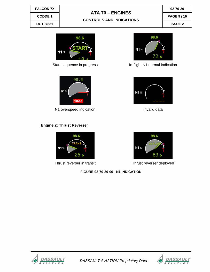
N1 INDICATION
ITEM DESCRIPTION
1 N1mini bug (anti-ice) when wings anti-ice selected ON
2 N1 indication
3 N1 commanded. The TLA magenta bug indicates Thrust Lever Angle. It shows the power required by the pilot. During acceleration or deceleration, the TLA bug and the needle indicating engine actual N1 may not be at the same location.
4 N1 Max cruise rating
5 N1 Max climb rating
6 N1 Max take off rating
7 N1 redline transient limit
8 START indication
9 N1 active limit digital readout
FALCON 7X 02-70-20
CODDE 1 PAGE 9 / 16
DGT97831
ATA 70 – ENGINES CONTROLS AND INDICATIONS
ISSUE 2
Start sequence in progress In-flight N1 normal indication
N1 overspeed indication
Invalid data
Engine 2: Thrust Reverser
Thrust reverser in transit Thrust reverser deployed
FIGURE 02-70-20-06 - N1 INDICATION
DASSAULT AVIATION Proprietary Data
02-70-20 FALCON 7X
PAGE 10 / 16 CODDE 1
ISSUE 2
ATA 70 – ENGINES CONTROLS AND INDICATIONS
DGT97831
DASSAULT AVIATION Proprietary Data
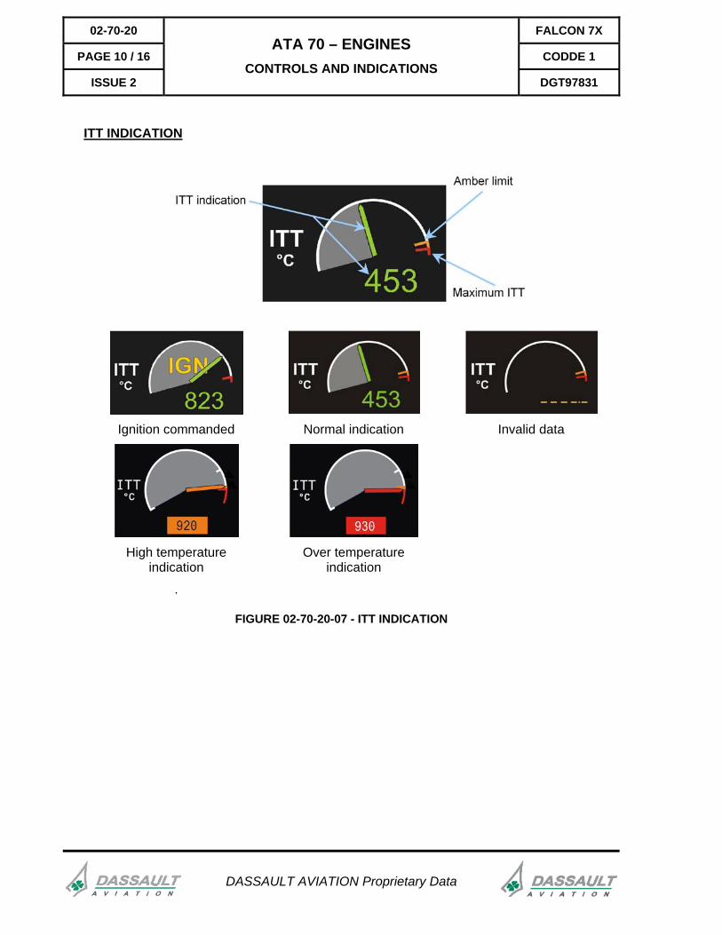
ITT INDICATION
Ignition commanded Normal indication Invalid data
High temperature indication
.
Over temperature indication
FIGURE 02-70-20-07 - ITT INDICATION
FALCON 7X 02-70-20
CODDE 1 PAGE 11 / 16
DGT97831
ATA 70 – ENGINES CONTROLS AND INDICATIONS
ISSUE 2
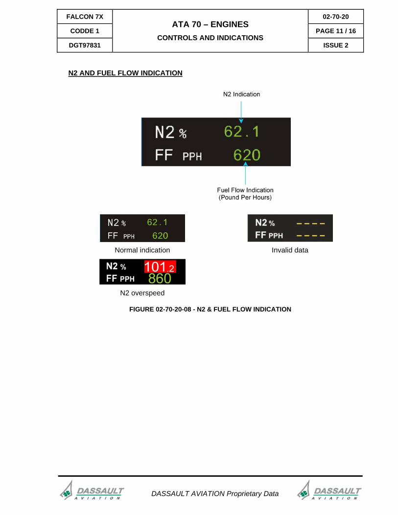
N2 AND FUEL FLOW INDICATION
Normal indication Invalid data
N2 overspeed
FIGURE 02-70-20-08 - N2 & FUEL FLOW INDICATION
DASSAULT AVIATION Proprietary Data
02-70-20 FALCON 7X
PAGE 12 / 16 CODDE 1
ISSUE 2
ATA 70 – ENGINES CONTROLS AND INDICATIONS
DGT97831
DASSAULT AVIATION Proprietary Data
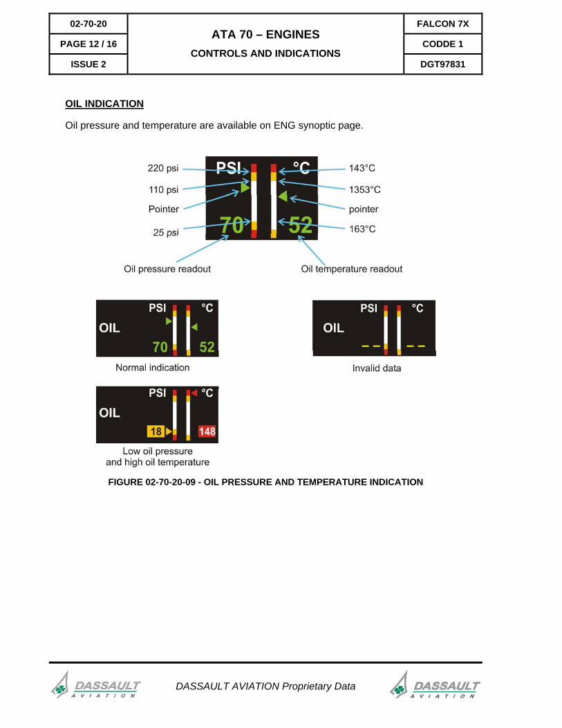
OIL INDICATION
Oil pressure and temperature are available on ENG synoptic page.
FIGURE 02-70-20-09 - OIL PRESSURE AND TEMPERATURE INDICATION
FALCON 7X 02-70-20
CODDE 1 PAGE 13 / 16
DGT97831
ATA 70 – ENGINES CONTROLS AND INDICATIONS
ISSUE 2
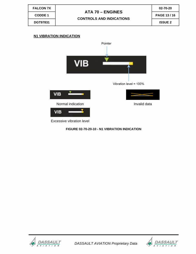
N1 VIBRATION INDICATION
Normal indication Invalid data
Excessive vibration level
FIGURE 02-70-20-10 - N1 VIBRATION INDICATION
DASSAULT AVIATION Proprietary Data
02-70-20 FALCON 7X
PAGE 14 / 16 CODDE 1
ISSUE 2
ATA 70 – ENGINES CONTROLS AND INDICATIONS
DGT97831
DASSAULT AVIATION Proprietary Data
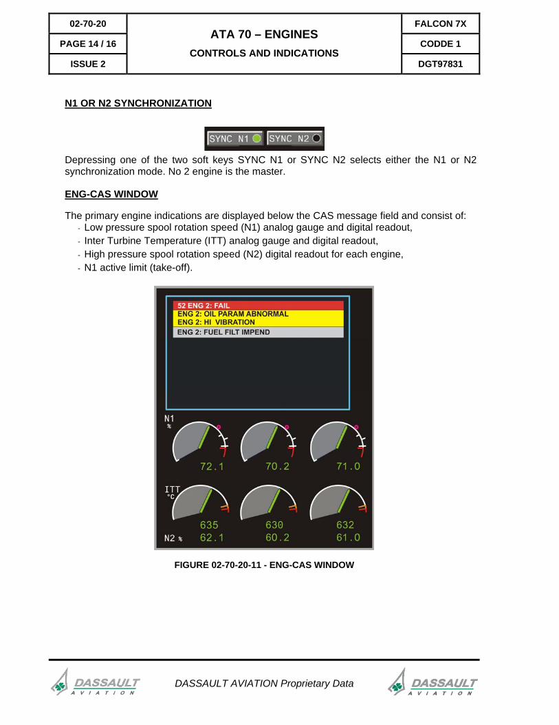
N1 OR N2 SYNCHRONIZATION
Depressing one of the two soft keys SYNC N1 or SYNC N2 selects either the N1 or N2 synchronization mode. No 2 engine is the master.
ENG-CAS WINDOW
The primary engine indications are displayed below the CAS message field and consist of: - Low pressure spool rotation speed (N1) analog gauge and digital readout, - Inter Turbine Temperature (ITT) analog gauge and digital readout, - High pressure spool rotation speed (N2) digital readout for each engine, - N1 active limit (take-off).
FIGURE 02-70-20-11 - ENG-CAS WINDOW
FALCON 7X 02-70-20
CODDE 1 PAGE 15 / 16
DGT97831
ATA 70 – ENGINES CONTROLS AND INDICATIONS
ISSUE 2
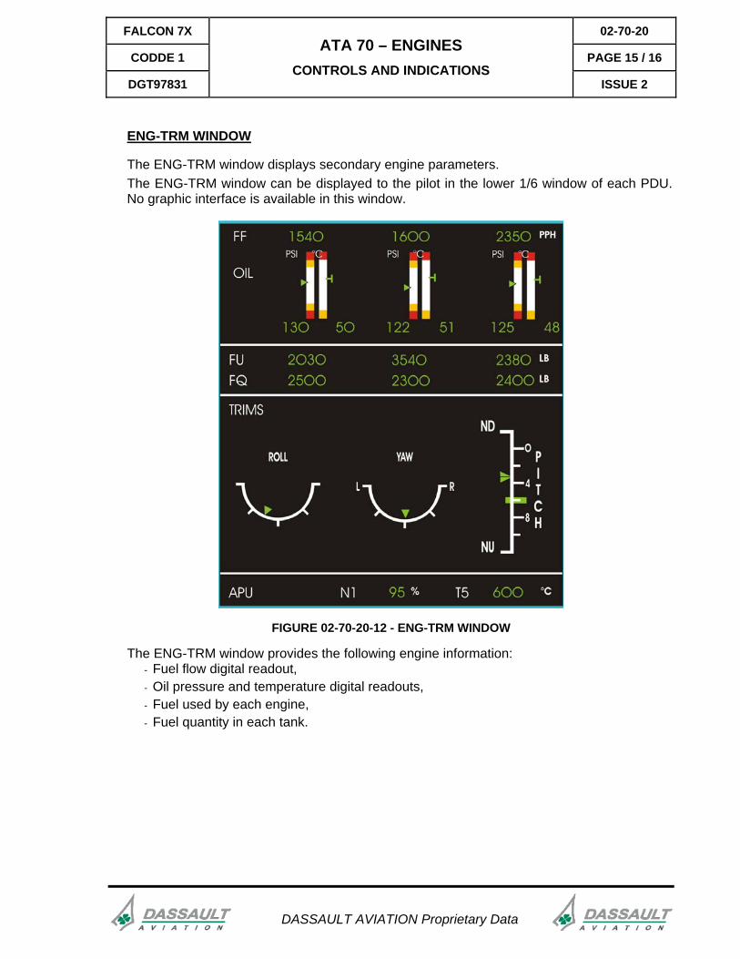
ENG-TRM WINDOW
The ENG-TRM window displays secondary engine parameters. The ENG-TRM window can be displayed to the pilot in the lower 1/6 window of each PDU. No graphic interface is available in this window.
FIGURE 02-70-20-12 - ENG-TRM WINDOW
The ENG-TRM window provides the following engine information: - Fuel flow digital readout, - Oil pressure and temperature digital readouts, - Fuel used by each engine, - Fuel quantity in each tank.
DASSAULT AVIATION Proprietary Data
02-70-20 FALCON 7X
PAGE 16 / 16 CODDE 1
ISSUE 2
ATA 70 – ENGINES CONTROLS AND INDICATIONS
DGT97831
DASSAULT AVIATION Proprietary Data
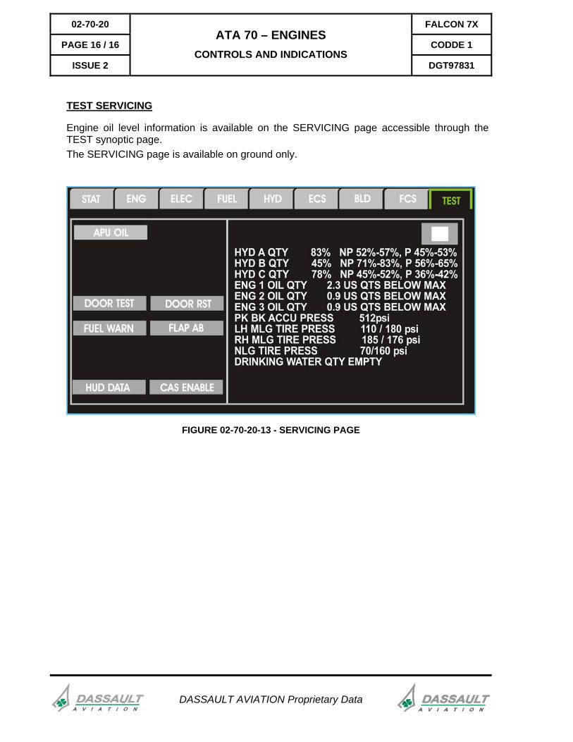
TEST SERVICING
Engine oil level information is available on the SERVICING page accessible through the TEST synoptic page. The SERVICING page is available on ground only.
FIGURE 02-70-20-13 - SERVICING PAGE
FALCON 7X 02-70-25
CODDE 1 PAGE 1 / 2
DGT97831
ATA 70 – ENGINES CONTROLS AND INDICATIONS -
SUPPLEMENTARY INFORMATION ISSUE 2
DASSAULT AVIATION Proprietary Data
No supplementary information to be provided on engine Controls and Indications at present time
FALCON 7X 02-70-30
CODDE 1 PAGE 1 / 2
DGT97831
ATA 70 – ENGINES SYSTEM PROTECTIONS
ISSUE 2
DASSAULT AVIATION Proprietary Data
SYSTEM MONITORING
Engine following systems and parameters are monitored:
- FADEC operational integrity,
- Air Turbine Starter Valve malfunctions,
- Hung start,
- Oil system (oil filter, oil level, oil chip),
- Fuel system (fuel filter),
- Parameters exceeding (N1, ITT, N2, vibrations, oil pressure, oil temperature).
- Engine flame out.
Refer to CODDE 2 for a complete list of CAS messages.
02-70-30 FALCON 7X
PAGE 2 / 2 CODDE 1
ISSUE 2
ATA 70 – ENGINES SYSTEM PROTECTIONS
DGT97831
DASSAULT AVIATION Proprietary Data
ACTIVE PROTECTIONS
The FADEC will automatically abort start if abnormal conditions are detected:
- IGV non properly positioned,
- No light off detected,
- N2 less than 5,2% for more than 20 seconds after start valve opening,
- N1 Signal loss with N2 at 50%.
The FADEC will maintain the ITT below 950°C without interrupting the sequence in case of hot start.
The FADEC control and limits some critical parameters during steady and transient operations:
- N1 & N2 Speed limits,
- ITT limit (Starting protection),
- Control of acceleration / deceleration (avoiding surge and overtemperature).
FALCON 7X 02-70-35
CODDE 1 PAGE 1 / 2
DGT97831
ATA 70 – ENGINES SYSTEM PROTECTIONS -
SUPPLEMENTARY INFORMATION ISSUE 2
DASSAULT AVIATION Proprietary Data
No supplementary information to be provided on engine protections at present time
FALCON 7X 02-70-40
CODDE 1 PAGE 1 / 2
DGT97831
ATA 70 – ENGINES GROUND OPERATION
ISSUE 2
DASSAULT AVIATION Proprietary Data
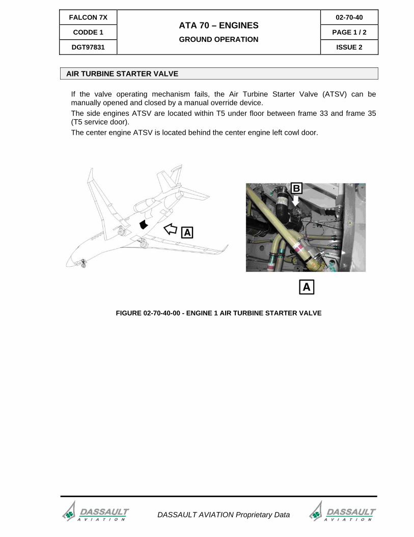
AIR TURBINE STARTER VALVE
If the valve operating mechanism fails, the Air Turbine Starter Valve (ATSV) can be manually opened and closed by a manual override device. The side engines ATSV are located within T5 under floor between frame 33 and frame 35 (T5 service door). The center engine ATSV is located behind the center engine left cowl door.
FIGURE 02-70-40-00 - ENGINE 1 AIR TURBINE STARTER VALVE
02-70-40 FALCON 7X
PAGE 2 / 2 CODDE 1
ISSUE 2
ATA 70 – ENGINES GROUND OPERATION
DGT97831
DASSAULT AVIATION Proprietary Data
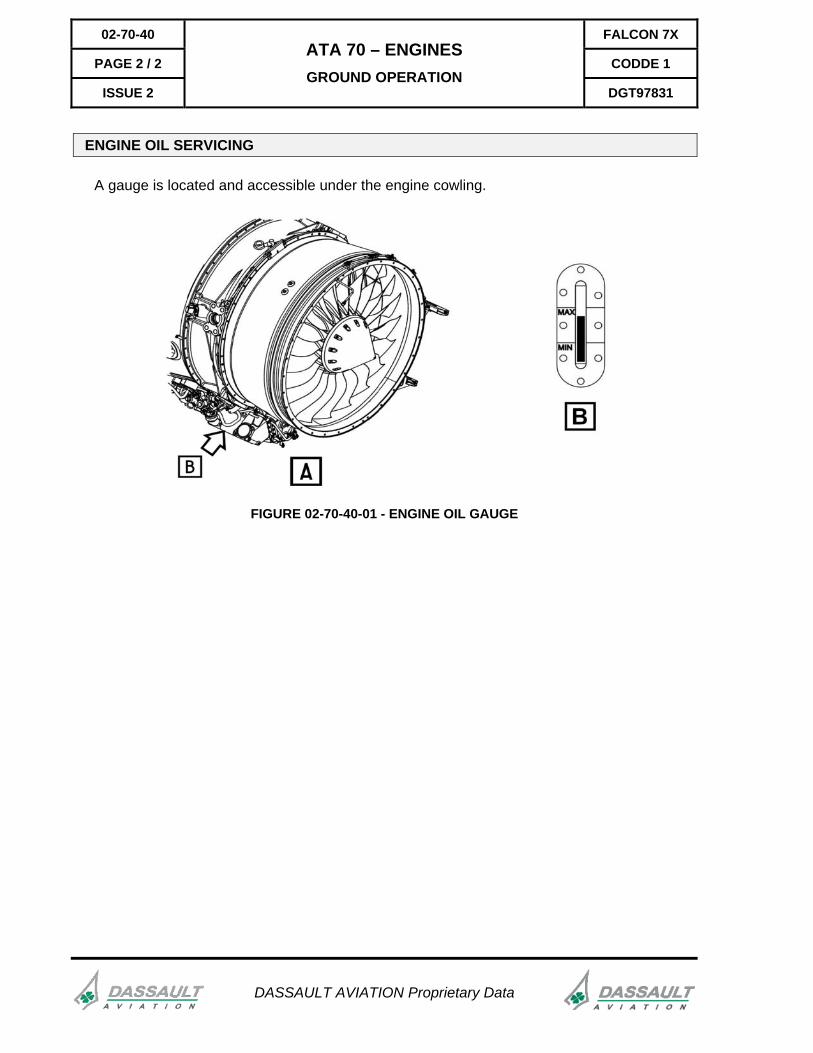
ENGINE OIL SERVICING
A gauge is located and accessible under the engine cowling.
FIGURE 02-70-40-01 - ENGINE OIL GAUGE