fabrication & experimental evaluation of heat transfer ......2.2 basic heat exchanger . fig. 2.1...
TRANSCRIPT

International Journal of Scientific & Engineering Research Volume 8, Issue 6, June-2017 534 ISSN 2229-5518
IJSER © 2017 http://www.ijser.org
Fabrication & Experimental Evaluation of Heat Transfer Enhancement Techniques in Heat
Exchangers Prem Kumar Vyda, Rupesh Palwadi, Ravi Chandra Parepalli
Abstract— Various heat enhancement techniques are identified and studied for double pipe heat exchangers. Experimental evaluation is done by fabricating basic double pipe heat exchanger and heat exchangers with modifications. Fabrication of heat exchangers is done as per the ISO standards. The material used for the construction of heat exchanger is copper, owing to its high thermal conductivity. Testing has been carried out for both parallel flow and counter flow connections at different flow rates. The results show that the three different enhancement techniques worked well, with the annular disks and the extended surfaces (fins) enhancement techniques, respectively, being the highest and the lowest. Experimental results of these modifications are validated using fluid flow analysis software; the software used here is Autodesk ALGOR Simulation Multiphysics. For this evaluation, 3D models of different variations of heat exchangers are generated using CATIA software. These models are then converted into *.iges format and the analysis is carried out. The analysis results validated the experimental results by showing that among the modified heat exchangers, heat exchanger with annular ring modification and the heat exchanger with extended surfaces (fins), respectively, has the highest and lowest heat transfer capability.
Keywords— Annular Rings, CATIA , Extended Surfaces , Flow Analysis , Heat Exchangers, Heat Transfer , LMTD.ALGOR Simulation
—————————— ——————————
1 INTRODUCTION eat exchangers are devices used to transfer heat energy from one fluid to another. Typical heat exchangers expe-
rienced by us in our daily lives include condensers and evapo-rators used in air conditioning units and refrigerators. Boilers and condensers in thermal power plants are examples of large industrial heat exchangers. There are heat exchangers in our automobiles in the form of radiators and oil coolers. Heat ex-changers are also abundant in chemical and process indus-tries. There are a wide variety of heat exchangers for diverse kinds of uses, hence the construction also would differ widely. However, in spite of the variety, most heat exchangers can be classified into some common types based on some fundamen-tal design concepts. Heat transfer enhancement in heat ex-changers is gaining industrial importance because it gives one the opportunity to reduce the heat transfer surface area required for a given application and thus reduce the heat exchanger size and cost, increase the heat duty of the exchanger for fixed sur-face area, reduce logarithmic mean temperature difference (LMTD) for fixed heat duty and surface area, and reduce pump-ing power for fixed heat duty and surface area. The automotive and refrigeration industries routinely use enhanced surfaces in their heat exchangers. Heat transfer enhancement in heat ex-changers has been the subject of many experimental and analyt-ical investigations. These techniques can be categorized as ‘ac-
tive’ or ‘passive’. The active techniques require external agita-tion, such as surface vibration, fluid vibration, injection, suction, and electric or acoustic fields. Passive techniques employ special surface geometries for enhancement, such as extended surfaces, rough surfaces, displacement enhancement devices, swirl flow devices, ob-struction devices, and treated surfaces. In the present work only passive enhancement techniques were considered. Three differ-ent ones were employed. One of these techniques is simple in-serts into the inner copper tube, while the other two were mod-ifications to the annulus. The insert device is a swirl flow device. This type of device is inserted into the flow channel to improve heat transfer indirectly by promoting turbulence and flow mix-ing. The swirl flow device was a twisted-tape insert. This creates rotating and/or secondary flow that enhances the heat transfer. One of the modifications to the annulus was the use of extended surfaces. This type of modification is routinely employed in many heat exchangers. Fins were placed on the outer surface of the copper tube. A special shape of the fin was employed to increase the heat transfer coefficient. Also, extended surfaces may take the form of interrupted fins, which forces the redeve-lopment of boundary layers. The other modification technique to the annulus was an obstruction device This was accom-plished by periodically restricting the flow with annulus rings or disks. The opening in the disk is located in the center and forces the liquid to pass through a narrow opening near the surface of the copper tube. Because this opening is much small-er than the rest of the annulus, the liquid velocity is high through the opening. The rapid expansion on the far side of the opening triggers transition from laminar to turbulent flow, thus enhancing the rate of heat transfer.
H
About the Authors • Prem Kumar Vyda is currently pursuing masters degree program in Me-
chanical & Mechatronics Engineering in University of Waterloo,Canada, PH-+1-519-998-0702. E-mail: [email protected]
• Rupesh Palwadi is currently pursuing masters degree program in Mechan-ical & Mechatronics Engineering in University of Waterloo,Canada,, PH-+1-519-572-4296. E-mail: [email protected]
• Ravi Chandra Parepalli is currently working as a design Engineer at TA-TA CONSULTANCY SERVICES LIMITED,Bengaluru,PH-+91-7382895457. E-Mail:[email protected]
IJSER

International Journal of Scientific & Engineering Research Volume 8, Issue 6, June-2017 535 ISSN 2229-5518
IJSER © 2017 http://www.ijser.org
2 DEVELOPMENT OF HEAT EXCHANGER 2.1 SPECIFICATIONS OF HEAT EXCHANGER USED The experimental study is done on a double pipe heat exchang-er having the specifications as listed below:- Specifications of Heat Exchanger: Inner pipe ID = 13.8mm Inner pipe OD = 15.8mm Outer pipe ID = 38mm Outer pipe OD = 42mm Material of construction = Copper Heat transfer length = 400mm Water at room temperature was allowed to flow through the inner pipe while hot water (set Point 55°C) flowed through the annulus side in the counter current direction.
2.2 BASIC HEAT EXCHANGER
Fig. 2.1 Fabricated model of a basic heat exchanger The heat exchanger is a simple, double-pipe heat exchanger. The inner tube is copper, of inside diameter 13.8 mm and out side diameter 15.8mm. The outer tube is a mild steel pipe with an inside diameter of 38mm and outside diameter of 42mm. Hot water flows through the copper tube and the cold water flows through the mild steel pipe. Two thermocouples are installed in each end, they measure the temperatures of the hot water, and the cold water. These measurements are neces-sary to determine the LMTD. The flow rates of both the cold and hot flows are controlled and measured by two separate flow rotameters. Depending on the connections of the inlet and the outlet of the cold flow, the heat exchanger can be op-erated either as a counter-flow heat exchanger or as a parallel-flow heat exchanger.
2.3 MODIFIED HEAT EXCHANGERS 2.3.1 Extended surfaces: Addition of fins to the outer surface of the copper tube. A total of 42 fins were placed on
the inner tube. These fins were placed in sev-en banks of six fins each. The six fins in each bank were radially spaced, in increments of 60 degrees, on the outside surface of the in-ner tube. The fins were made of copper due to its high thermal conductivity. The maxi-mum allowable fin height based on the outer diameter of the tube and the inner diameter of the shell was calculated to be 11.1mm. Given this constraint, a fin height of 11mm was chosen for ease of manufacturability, assembly, and material availability. The fin thickness was chosen to be 0.8inch, since ma-
terial of this gage was readily available and inexpensive. The base of each fin was soldered to the inner copper tube. Plumb-ing solder was used because of its the surface area, but they also increase turbulence, and induce a mixing effect inside the water jacket. This was accomplished by bending the top-rear corner of the fin towards the center of the tube. The increase in turbulence and the induced mixing tend to increase the heat transfer coefficient 2.3.2 OBSTRUCTION DEVICES: ANNULAR RINGS OR DISKS Orifices or other temporary restrictions to flow often induce turbu-lence. Our approach, therefore, was periodically to restrict the flow with annular rings or disks. A schematic of the disk/ring is shown in Fig. The opening in the disk is in the center. This forces all the fluid to pass through a narrow opening near the surface of the copper tube. Because this opening is much smaller than the rest of the annulus, velocity is high through the opening. Also, the rapid expansion on the opposite side of the opening triggers the transition from laminar to turbulent flow. The outside edges of the disks are sealed to the mild steel pipe to force the fluid through the narrow opening near the copper tube. The resulting high liquid velocity and flow turbulence tend to increase the heat transfer coefficient. The problem is then how to install and support the annular disks inside the mild steel pipe. The method that was chosen was to make the disk an integral part of a thin walled tube that slipped inside the mild steel pipe. To do this, seven annular disks were made and in-stalled. The end result was a tube 400 mm long, with disks having a 1.5mm openings spaced on 50mm centers along the tube.
2.3.3 Swirl flow device: a Twisted-tape insert The thin twisted helical tape was made of a copper sheet
(1.6 mm thick). The tape was twisted eight times. There was a small clearance between the twisted tape and the walls of the copper tube to allow easy insertion of the tape. The work by Manglik and Bergles on twisted tapes presented an updated understanding of the heat transfer for both laminar and turbu-lent flows. The blockage caused by the finite tape thickness increases the average velocity. Heat transfer enhancement may occur for two reasons. First, the tape reduces the hydrau-lic diameter of the inner copper tube; this tends to increase the heat transfer coefficient, even for zero tape twist. Secondly, the twist of the tape causes a tangential velocity component. This causes the speed of the flow to increase, particularly near the wall. The enhancement in the heat transfer is a result of the mixing by the secondary flow and the increased shear stress at the wall.
IJSER

International Journal of Scientific & Engineering Research Volume 8, Issue 6, June-2017 536 ISSN 2229-5518
IJSER © 2017 http://www.ijser.org
3 EXPERIMENTATION WITH VARIATIONS 3.1 EXPERIMENTAL SETUP Testing was done and compared the three modified heat ex-changers to the basic heat exchanger. First, the basic heat ex-changer was set up to both hot and cold water flows in a coun-ter-flow mode and parallel flow mode . The cold water flow was an open circuit while the hot water flow was a closed cir-cuit. The water was heated to the desired temperature by heat-ing element. Adjusting the electrical energy input to the heat-ing element controlled the water temperature.
Both rates of flows were controlled by rotameters. The tem-peratures at the inlet and exit were measured by the use of four thermocouples that were connected to a data acquisition device. After the system had reached steady-state conditions the following data were measured and recorded: hot water flow rate, cooling water flow rate, inlet and exit hot water temperatures, Thi and Tho, respectively and inlet and exit cooling water temperatures, Tci and Tco, respectively. This was carried out for several flow rates. In order to evaluate the enhancement techniques, the same experimental procedure was repeated for the modified heat exchangers and data were recorded for the same experimental conditions. There are sev-eral parameters that can be determined from these measure-ments, such as the heat duty, Q, the overall heat transfer coef-ficient, U, and the LMTD, that can be employed in the evalua-tion of the degree of enhancement of the modified heat ex-changers presents the performance, based on heat duty, Q, of the basic and the four modified heat exchangers. The four dif-ferent enhancement techniques performed well, with the an-nular disks and the spiraled rod enhancement techniques, re-spectively, being the highest and the lowest. 3.2 RESULTS AND DISCUSSIONS
The results obtained for various variations in both parallel
flow and counter flow are tabulated and plotted. Various for-mulae used for calculating the experimentation variables:
Plot 3.1 Mc vs Q FOR PARALLEL FLOW:
X- Axis – Mass flow rate of cold water (LPM) Y- Axis – Heat Loss from Hot Flow (Watts)
It is observed that the heat exchanger with annular disc has the highest heat loss from hot flow followed by heat exchanger with twisted tape insert and then heat exchanger with fins. The amount of heat loss also increases with increase in mass flow rate of cold water. Plot 3.2 Mc vs Q FOR COUNTER FLOW:
X- Axis – Mass flow rate of cold water (LPM)
Y- Axis – Heat Loss from Hot Flow (Watts)
It is observed that the heat exchanger with annular disc has the highest heat loss from hot flow followed by heat exchanger with twisted tape insert and then heat exchanger with fins. The amount of heat loss also increases with increase in mass flow rate of cold water in the counter flow conditions also.
IJSER

International Journal of Scientific & Engineering Research Volume 8, Issue 6, June-2017 537 ISSN 2229-5518
IJSER © 2017 http://www.ijser.org
Plot 3.3 Mc vs U FOR PARALLEL FLOW:
X- Axis – Mass flow rate of cold water (LPM) Y- Axis – Overall heat transfer coefficient (W/m2k)
It is observed that the heat exchanger with annular disc has the highest overall heat transfer coefficient followed by heat exchanger with twisted tape insert and heat exchanger with fins. The overall heat transfer coefficient also increases with increase in mass flow rate of cold water.
Plot 3.4 Mc vs U FOR COUNTER FLOW: It is observed that the heat exchanger with annular disc has the highest overall heat transfer coefficient followed by heat exchanger with twisted tape insert and heat exchanger with fins. The overall heat transfer coefficient also increases with increase in mass flow rate of cold water in counter flow condi-tions also.
4 VALIDATION WITH COMPUTER MODELING 4.1 3D MODELLING OF HEAT EXCHANGERS
CATIA (Computer Aided Three-dimensional Interactive Application) is a multi-platform CAD/CAM/CAE commer-cial software suite developed by the French company Dassault Systemes. Written in the C++ programming language, CATIA is the cornerstone of the Dassault Systemes product lifecycle management software suite. Through its exceptionally easy to use user interface, it delivers maximum productivity and crea-tivity from concept to final product.
The Fabricated Designs are made in CATIA Software and exported to *.iges format for further Analysis.The different designs modeled are shown.
Fig. 4.1 A 270° cut section view of the basic heat exchanger
Fig. 4.2 A 180° cut section view of the finned heat exchanger
Fig. 4.3 Cut section view of twisted tape insert
IJSER

International Journal of Scientific & Engineering Research Volume 8, Issue 6, June-2017 538 ISSN 2229-5518
IJSER © 2017 http://www.ijser.org
5 SIMULATION USING AUTODESK ALGOR 5.1 SIMULATION SETUP
Various analysis types are available in this software and Multi-Physics module is used in this Analysis. After convert-ing the file into the *.iges format , the computer model can be imported into the software by selecting open button or by pressing ctrl+o
. Fig 5.1 Imported Part into ALGOR
After the model has been imported into the analysis software, for the analysis to be performed , the model must be meshed in order to evaluate the results. The mesh contains various nodes and nodal elements at which the values can be calcu-lated by the solver. The model mesh settings option allows us to select the various meshing parameters to make the mesh for the geometry as per the desired specification. The lower the meshing size, the more are the number of nodes and nodal elements and the more accurate the result that can be obtained. The model mesh settings window can be ob-tained by clicking on the respective button on the taskbar. Now the mesh type to be selected is of solid mesh and the pointer to be dragged to 60% of the original mesh value. Now click on the options button and another dialog box will pop up requesting for further mesh details as shown below. Now, on the left hand side of the dialog box obtained, select the solid and selet the tetrahedral and wedges (boundary layer). This type of mesh setting is selected as the analysis criterion here involves fluid flow in combination with heat transfer analysis. We have selected this type of mesh setting as it involves a boundary layer flow without including viscous heating effects.This type of mesh setting enables us to make the part as a water tight jointed part as the said part is as-sumed to be carrying water.
Now , after clicking on the mesh model button on the mesh settings dialog box, the meshing will be done and the mesh is verified for any errors in the resulting mesh after the meshing operation is done. After the mesh is verified for errors and if there are no errors found , then the part will be meshed suc-cessfully.
Fig 5.2 Meshed Model Now, before performing the analysis, initially, some analysis parameters have to be specified and some initial setting has to be done with the part geometry. Firstly, the unit systems have to be changed to the SI system of units so as to benefit the ease of calculation. Next, the analysis type has to be specified so that the solver can understand the problem definition and pass the required criteria of information and parsers (evaluators) specific to that problem definition. In the process of changing the analysis parameters, a pop up window will ask for the change of design scenario of the cur-rent analysis. Design scenarios help us to perform one or more analysis on the same part repeatedly. In such situations, select NO in the resulting pop up dialog box to retain the original parameters. If YES is pressed, then newer parameters has to be passed. Here, we use the coupled fluid flow and themal analysis as it involves both the heat transfer and fluid flow simulation.
To change the analysis type, on the left hand side of the GUI(Graphical User Interface of the software), right click on the analysis type and select the set current analysis type and in the resulting sub-menu select the multiphysics option through which another sub menu will result in. select the steady state one from the menu. Now the analysis specification is over and the change of analysis type dialog box results in pressing NO on it and the present scenario is used.
Fig 5.2 Passing Parameters
IJSER

International Journal of Scientific & Engineering Research Volume 8, Issue 6, June-2017 539 ISSN 2229-5518
IJSER © 2017 http://www.ijser.org
The analysis can be continued by coupling steady state heat transfer with steady fluid flow simulation and results in the same output as the coupled fluid analysis. This method of coupling them individually involves an ease in the analysis and also results in a more accurate result orientation. This is the best method preferred for performing the analysis as the other me-thod consumes a lot of time and processor resources and results obviously in errors and bug tracking phenomena. Now, the various parameters like heat flux and the temperature inputs are given as follows.
Fig 5.3The material selection window for fluid flow
The various parameters that have to be given are as shown be-low .They can be incorporated by selecting the various surfaces and their respective fluid or heat flux domains and applying them carefully as any change may lead to erratic results. Fig 5.4 Fluid and Heat Flux Parameters
Now the fluid domain must be created in order to make the fluid flow simulation and the selected design scenario active.be accomplished by selecting the internal fluid generation from the mesh option in the toolbar. The internal fluid generation option is selected as the fluid flows within both the tubes only. Now, we have to select the surfaces that are adjacent to the fluid domain to make the fluid flow domain closed without any leaks. Now the parameters for the multiphysics and the fluid flow are given by clicking on the analysis button on the taskbar and se-lecting the parameters option. After all the input parameters are provide in the software for the part geometry, the direction of fluid flow and the heat fluxes are represented by arrows and yellow rings respectively.
Fig 5.5 Internal Fluid generation window
5.2 PERFORMING ANALYSIS After assuring that all the input parameters are declared , the perform analysis button is clicked and then the software once again verifies for the validation of the information and the mesh-ing details and then continues to the solver and initiates the solv-er. We can be assured of the completeness of the input parameters when there is nothing marked red on the left hand side of the software window. The analysis will continue to be performed for the geometry.Now, after the analysis has been performed the results are evaluated and then displayed in the hyperview 4.0 environment module and the various results can be obtained henceforth.
Fig 5.6 Simulation in Progress
IJSER
International Journal of Scientific & Engineering Research Volume 8, Issue 6, June-2017 540 ISSN 2229-5518
IJSER © 2017 http://www.ijser.org
5.3 RESULTS
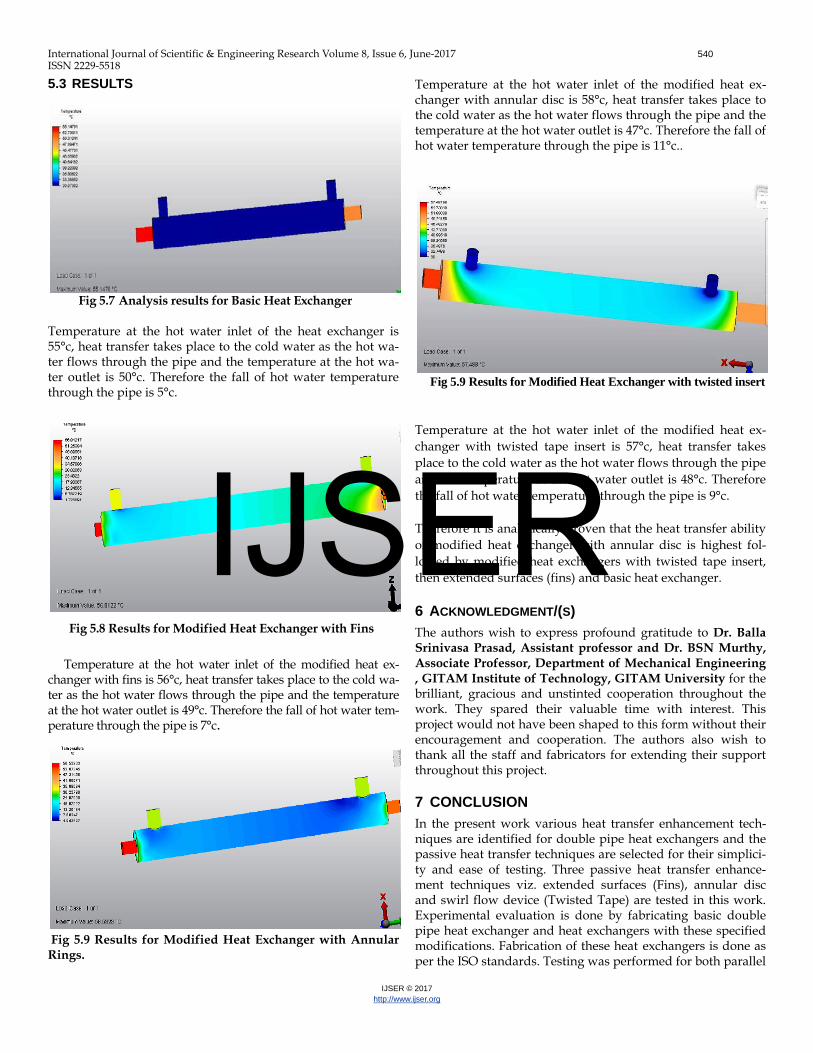
Fig 5.7 Analysis results for Basic Heat Exchanger Temperature at the hot water inlet of the heat exchanger is 55°c, heat transfer takes place to the cold water as the hot wa-ter flows through the pipe and the temperature at the hot wa-ter outlet is 50°c. Therefore the fall of hot water temperature through the pipe is 5°c.
Fig 5.8 Results for Modified Heat Exchanger with Fins
Temperature at the hot water inlet of the modified heat ex-changer with fins is 56°c, heat transfer takes place to the cold wa-ter as the hot water flows through the pipe and the temperature at the hot water outlet is 49°c. Therefore the fall of hot water tem-perature through the pipe is 7°c.
Fig 5.9 Results for Modified Heat Exchanger with Annular Rings.
Temperature at the hot water inlet of the modified heat ex-changer with annular disc is 58°c, heat transfer takes place to the cold water as the hot water flows through the pipe and the temperature at the hot water outlet is 47°c. Therefore the fall of hot water temperature through the pipe is 11°c..
Fig 5.9 Results for Modified Heat Exchanger with twisted insert Temperature at the hot water inlet of the modified heat ex-changer with twisted tape insert is 57°c, heat transfer takes place to the cold water as the hot water flows through the pipe and the temperature at the hot water outlet is 48°c. Therefore the fall of hot water temperature through the pipe is 9°c. Therefore it is analytically proven that the heat transfer ability of modified heat exchanger with annular disc is highest fol-lowed by modified heat exchangers with twisted tape insert, then extended surfaces (fins) and basic heat exchanger.
6 ACKNOWLEDGMENT/(S) The authors wish to express profound gratitude to Dr. Balla Srinivasa Prasad, Assistant professor and Dr. BSN Murthy, Associate Professor, Department of Mechanical Engineering , GITAM Institute of Technology, GITAM University for the brilliant, gracious and unstinted cooperation throughout the work. They spared their valuable time with interest. This project would not have been shaped to this form without their encouragement and cooperation. The authors also wish to thank all the staff and fabricators for extending their support throughout this project.
7 CONCLUSION In the present work various heat transfer enhancement tech-niques are identified for double pipe heat exchangers and the passive heat transfer techniques are selected for their simplici-ty and ease of testing. Three passive heat transfer enhance-ment techniques viz. extended surfaces (Fins), annular disc and swirl flow device (Twisted Tape) are tested in this work. Experimental evaluation is done by fabricating basic double pipe heat exchanger and heat exchangers with these specified modifications. Fabrication of these heat exchangers is done as per the ISO standards. Testing was performed for both parallel
IJSER

International Journal of Scientific & Engineering Research Volume 8, Issue 6, June-2017 541 ISSN 2229-5518
IJSER © 2017 http://www.ijser.org
flow and counter flow connections at different flow rates. The results show that the three different enhancement techniques worked well, with the annular discs and the extended surfaces (fins) enhancement techniques, respectively, being the highest and the lowest. Experimental results of these modifications are validated using a fluid flow analysis software. For this, 3D models of different variations of heat exchangers are generat-ed using CATIA software. These models are then converted to *.iges format and the analysis were done. The analysis results have validated the experimental results by showing that among the modified heat exchangers, heat exchanger with annular disc modification and the heat exchanger with ex-tended surfaces (fins), respectively, has the highest and lowest heat transfer capability
8 SCOPE OF FUTURE WORK In the present work only passive heat transfer techniques are used for a double pipe heat exchanger. These techniques can be extended to other type of heat exchangers. Active tech-niques can also be effective for heat transfer enhancement. These active techniques can be used in combination with the passive techniques for improving the heat transfer ability. Pas-sive techniques can also be used in different combinations for enhancing the heat transfer rate
9 REFERENCES [1] B.Adrian and K. Allan D. “Heat transfer enhancement”. In Heat
Transfer Handbook, Chapter 14, pg.1033, -1101, Wiley-interscience, 2003.
[2] Bergles, A.E. “Techniques to augment heat transfer” In Handbook of Heat Transfer Applications (Ed.W.M. Rosenhow), 1985, Ch.3 (McGraw-Hill, New York).
[3] E. Bergles, R. L. Webb, G. H. Junkan “Energy conservation via heat
transfer enhancement”. [4] M. Siddique, A.-R. A. Khaled, N. I. Abdulhafiz, and A. Y. Boukhary
“Recent Advances in Heat Transfer Enhancements: A Review Re-port”.
[5] R. L. Webb “Performance evaluation criteria for use of enhanced
heat transfer surfaces in heat exchanger design” [6] P. Bharadwaj, A.D. Khondge, A.W. Date “Heat transfer and pressure
drop in a spirally grooved tube with twisted tape Insert”
[7] R. M. Manglik and A. E. Bergles “Heat transfer enhancement and pressure drop in viscous liquid flows in isothermal tubes with twisted-tape inserts”
[8] P.K. Sarma, P.S. Kishore, V. Dharma Rao, T. Subrahmanyam “A
combined approach to predict friction coefficients and convective heat transfer characteristics in a tube with twisted tape inserts for a wide range of Re and Pr.”
[9] Francis Agyenim , Philip Eames , Mervyn Smyth “A comparison of
heat transfer enhancement in a medium temperature thermal energy storage heat exchanger using fins”
[10] S. Al-Fahed , L.M. Chamra , W. Chakroun “Pressure drop and heat
transfer comparison for both microfin tube and twisted-tape inserts in laminar flow”
[11] “Experimental Measurements Of Heat Transfer In An Internally
Finned Tube” Mafizul Huq and A.M. Aziz-ul Huq, Muhammad Mustafizur Rahman.
[12] Leonard L. Vasiliev “Heat pipes in modern heat exchangers”.
[13] “Heat transfer augmentation in a heat exchanger tube using a baffle” Nasiruddin, M.H. Kamran Siddiqui [14] Shyy Woei Chang , Yih Jena Jan , Jin Shuen Liou “Turbulent heat
transfer and pressure drop in tube fitted with serrated twisted tape”.
[15] P. Sivashanmugam , S. Suresh “Experimental studies on heat transfer and friction factor characteristics of laminar flow through a circular tube fitted with helical screw-tape inserts.”
[16] Smith Eiamsa-ard, Pongjet Promvonge “Enhancement of heat trans-
fer in a tube with regularly-spaced helical tape swirl generators”.
[17] Fabrication and Experimental Evaluation of Heat Transfer Enhance-ment Methods in Heat Exchanges”, P. Anipey, L. S. V.Prasad, B. S. Prasad, and B. S. N. Murthy, IJAEA-2-1-3 , International Journal of Advanced Engineering Applications , Volume 3 , 2013
[18] Catia V5r16 For Designers Pdf Document.
[19] Catia Tutorials From Cadtutor.Net
[20] Catia Tutorials From Catiastudent.Com
[21] Autodesk Student Community
[22] Video Tutorials From Youtube.com
IJSER