f2000ex easy 02-26-00 ata 26 – fire protection codde …ata 26 – fire protection general issue 3...
TRANSCRIPT
F2000EX EASY 02-26-00
CODDE 1 PAGE 1 / 2
DGT94085
ATA 26 – FIRE PROTECTION TABLE OF CONTENTS
ISSUE 3
DASSAULT AVIATION Proprietary Data
02-26 ATA 26 – FIRE PROTECTION
02-26-00 TABLE OF CONTENTS
02-26-05 GENERAL
Introduction Sources
02-26-10 DESCRIPTION
Introduction Fire detection Fire extinguishing Portable fire extinguishers
02-26-15 CONTROL AND INDICATION
Control Indication
02-26-20 SYSTEM PROTECTION
Introduction Circuit breakers Cylinder overpressure protection
02-26-25 NORMAL OPERATION
Introduction Engine and apu fire extinguishing Wheel well / forward comp / bag comp / smoke in toilet Fire test operation
02-26-30 ABNORMAL OPERATION
CAS messages

02-26-00 F2000EX EASY
PAGE 2 / 2 CODDE 1
ISSUE 3
ATA 26 – FIRE PROTECTION TABLE OF CONTENTS
DGT94085
DASSAULT AVIATION Proprietary Data
INTENTIONALLY LEFT BLANK
F2000EX EASY 02-26-05
CODDE 1 PAGE 1 / 4
DGT94085
ATA 26 – FIRE PROTECTION GENERAL
ISSUE 3
DASSAULT AVIATION Proprietary Data
INTRODUCTION
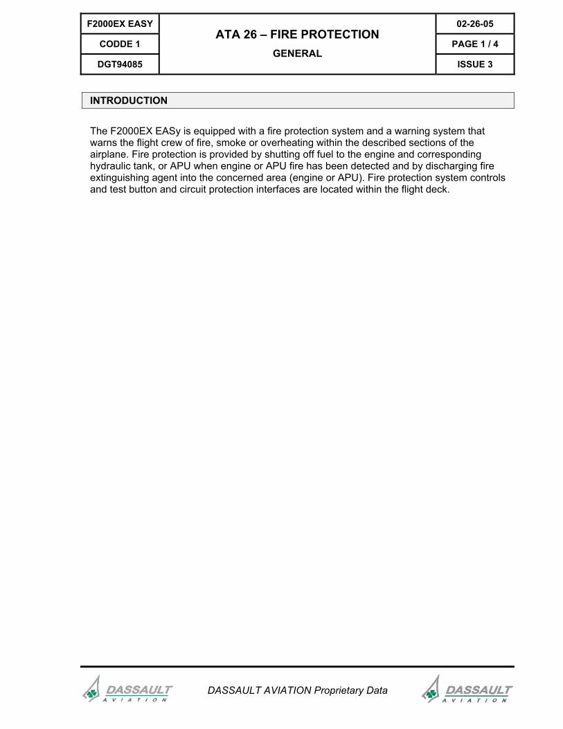
The F2000EX EASy is equipped with a fire protection system and a warning system that warns the flight crew of fire, smoke or overheating within the described sections of the airplane. Fire protection is provided by shutting off fuel to the engine and corresponding hydraulic tank, or APU when engine or APU fire has been detected and by discharging fire extinguishing agent into the concerned area (engine or APU). Fire protection system controls and test button and circuit protection interfaces are located within the flight deck.
02-26-05 F2000EX EASY
PAGE 2 / 4 CODDE 1
ISSUE 3
ATA 26 – FIRE PROTECTION GENERAL
DGT94085
DASSAULT AVIATION Proprietary Data
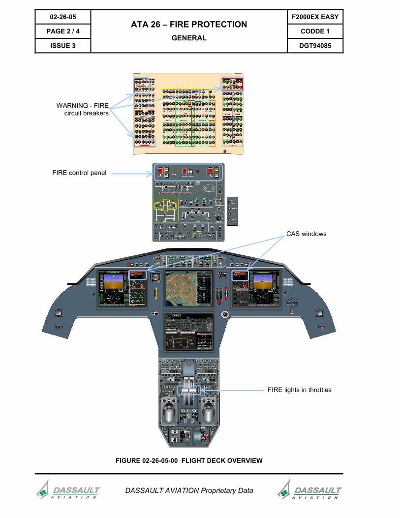
WARNING - FIREcircuit breakers
FIRE control panel
CAS windows
FIRE lights in throttles
FIGURE 02-26-05-00 FLIGHT DECK OVERVIEW

F2000EX EASY 02-26-05
CODDE 1 PAGE 3 / 4
DGT94085
ATA 26 – FIRE PROTECTION GENERAL
ISSUE 3
DASSAULT AVIATION Proprietary Data
SOURCES
Fire extinguishing is provided by a total of three fire cylinders located in the aft servicing compartment. Two portable fire extinguishers (one more optional for public transport operation) are available to the crew.
AFT SERVICING COMPARTMENT CABIN AREA
Two extinguisher cylinders are allocated to the engines. One is allocated to the APU.
Two or three portable 2.5 lb. halon extinguishers are allocated to the flight deck, cabin and baggage compartment.
3 fire extinguishercylinders
3 portable fireextinguishers
FIGURE 02-26-05-01 FIRE EXTINGUISHER CYLINDERS LOCATION
02-26-05 F2000EX EASY
PAGE 4 / 4 CODDE 1
ISSUE 3
ATA 26 – FIRE PROTECTION GENERAL
DGT94085
DASSAULT AVIATION Proprietary Data
INTENTIONALLY LEFT BLANK
F2000EX EASY 02-26-10
CODDE 1 PAGE 1 / 6
DGT94085
ATA 26 – FIRE PROTECTION DESCRIPTION
ISSUE 3
DASSAULT AVIATION Proprietary Data
INTRODUCTION
The airplane is equipped with a fire protection system which provides the flight crew with detection, warning, fuel and hydraulic shut-off and fire extinguishing capability. Fire detection is provided for both engines, the APU, the baggage compartment, the forward servicing compartment and the main wheel wells. The rear and forward toilets can also be equipped with (optional) smoke detectors that will activate a message within the CAS window displays. Remote controlled fire extinguishing is provided for both engines and the APU. The overhead control panel and CAS windows provide the fire protection system interfaces and controls for the flight crew. The throttles are fitted with warning lights displaying engine fire.
02-26-10 F2000EX EASY
PAGE 2 / 6 CODDE 1
ISSUE 3
ATA 26 – FIRE PROTECTION DESCRIPTION
DGT94085
DASSAULT AVIATION Proprietary Data
FIRE DETECTION
Engine No 2
APU
Overheatsensors
Capillarylines
Capillary line Engine No 1
Smoke detector
Aft servicingcompartment
BaggagecompartmentWheel
wellsForwardservicing
compartment
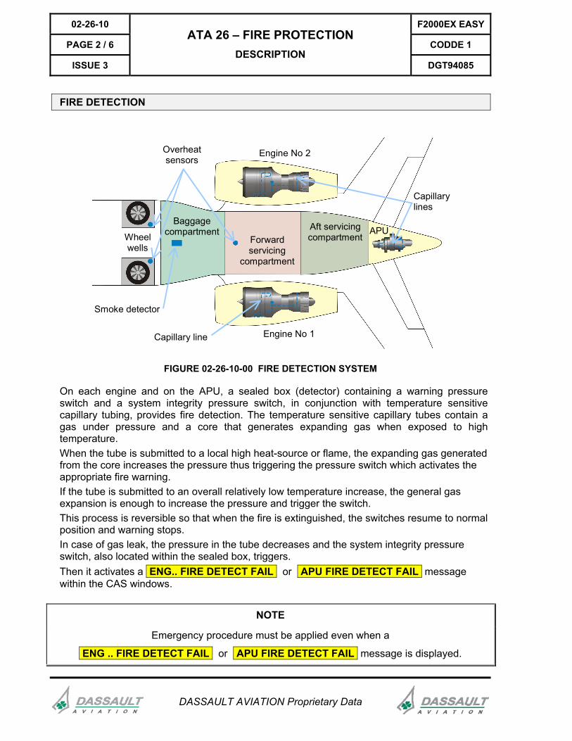
FIGURE 02-26-10-00 FIRE DETECTION SYSTEM
On each engine and on the APU, a sealed box (detector) containing a warning pressure switch and a system integrity pressure switch, in conjunction with temperature sensitive capillary tubing, provides fire detection. The temperature sensitive capillary tubes contain a gas under pressure and a core that generates expanding gas when exposed to high temperature. When the tube is submitted to a local high heat-source or flame, the expanding gas generated from the core increases the pressure thus triggering the pressure switch which activates the appropriate fire warning. If the tube is submitted to an overall relatively low temperature increase, the general gas expansion is enough to increase the pressure and trigger the switch. This process is reversible so that when the fire is extinguished, the switches resume to normal position and warning stops. In case of gas leak, the pressure in the tube decreases and the system integrity pressure switch, also located within the sealed box, triggers. Then it activates a ENG.. FIRE DETECT FAIL or APU FIRE DETECT FAIL message within the CAS windows.
NOTE
Emergency procedure must be applied even when a
ENG .. FIRE DETECT FAIL or APU FIRE DETECT FAIL message is displayed.
F2000EX EASY 02-26-10
CODDE 1 PAGE 3 / 6
DGT94085
ATA 26 – FIRE PROTECTION DESCRIPTION
ISSUE 3
DASSAULT AVIATION Proprietary Data
ENG .. FIRE DETECT FAIL
APU FIRE DETECT FAIL
or
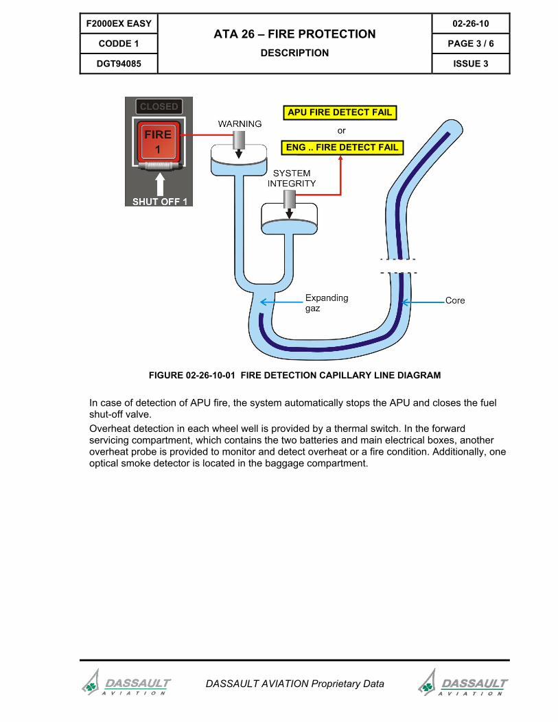
FIGURE 02-26-10-01 FIRE DETECTION CAPILLARY LINE DIAGRAM
In case of detection of APU fire, the system automatically stops the APU and closes the fuel shut-off valve. Overheat detection in each wheel well is provided by a thermal switch. In the forward servicing compartment, which contains the two batteries and main electrical boxes, another overheat probe is provided to monitor and detect overheat or a fire condition. Additionally, one optical smoke detector is located in the baggage compartment.
02-26-10 F2000EX EASY
PAGE 4 / 6 CODDE 1
ISSUE 3
ATA 26 – FIRE PROTECTION DESCRIPTION
DGT94085
DASSAULT AVIATION Proprietary Data
FIRE EXTINGUISHING
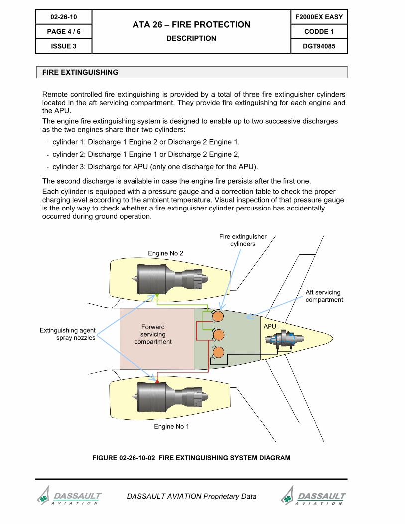
Remote controlled fire extinguishing is provided by a total of three fire extinguisher cylinders located in the aft servicing compartment. They provide fire extinguishing for each engine and the APU. The engine fire extinguishing system is designed to enable up to two successive discharges as the two engines share their two cylinders:
- cylinder 1: Discharge 1 Engine 2 or Discharge 2 Engine 1,
- cylinder 2: Discharge 1 Engine 1 or Discharge 2 Engine 2,
- cylinder 3: Discharge for APU (only one discharge for the APU).
The second discharge is available in case the engine fire persists after the first one. Each cylinder is equipped with a pressure gauge and a correction table to check the proper charging level according to the ambient temperature. Visual inspection of that pressure gauge is the only way to check whether a fire extinguisher cylinder percussion has accidentally occurred during ground operation.
Fire extinguishercylinders
Extinguishing agentspray nozzles
APUForwardservicing
compartment
Engine No 1
Engine No 2
Aft servicingcompartment
FIGURE 02-26-10-02 FIRE EXTINGUISHING SYSTEM DIAGRAM
F2000EX EASY 02-26-10
CODDE 1 PAGE 5 / 6
DGT94085
ATA 26 – FIRE PROTECTION DESCRIPTION
ISSUE 3
DASSAULT AVIATION Proprietary Data
PORTABLE FIRE EXTINGUISHERS
Additionally, two or three 2.5 lb (1.13 kg) Halon portable extinguishers, located in the forward crew closet and cabin area (one located on the aft face of LH forward galley bulkhead is optional for public transport operation), are available in the event the crew has to extinguish a fire in the cabin or baggage compartment.
For more information, refer to CODDE 1 / ATA 25.

02-26-10 F2000EX EASY
PAGE 6 / 6 CODDE 1
ISSUE 3
ATA 26 – FIRE PROTECTION DESCRIPTION
DGT94085
DASSAULT AVIATION Proprietary Data
INTENTIONALLY LEFT BLANK
F2000EX EASY 02-26-15
CODDE 1 PAGE 1 / 4
DGT94085
ATA 26 – FIRE PROTECTION CONTROL AND INDICATION
ISSUE 3
DASSAULT AVIATION Proprietary Data
CONTROL
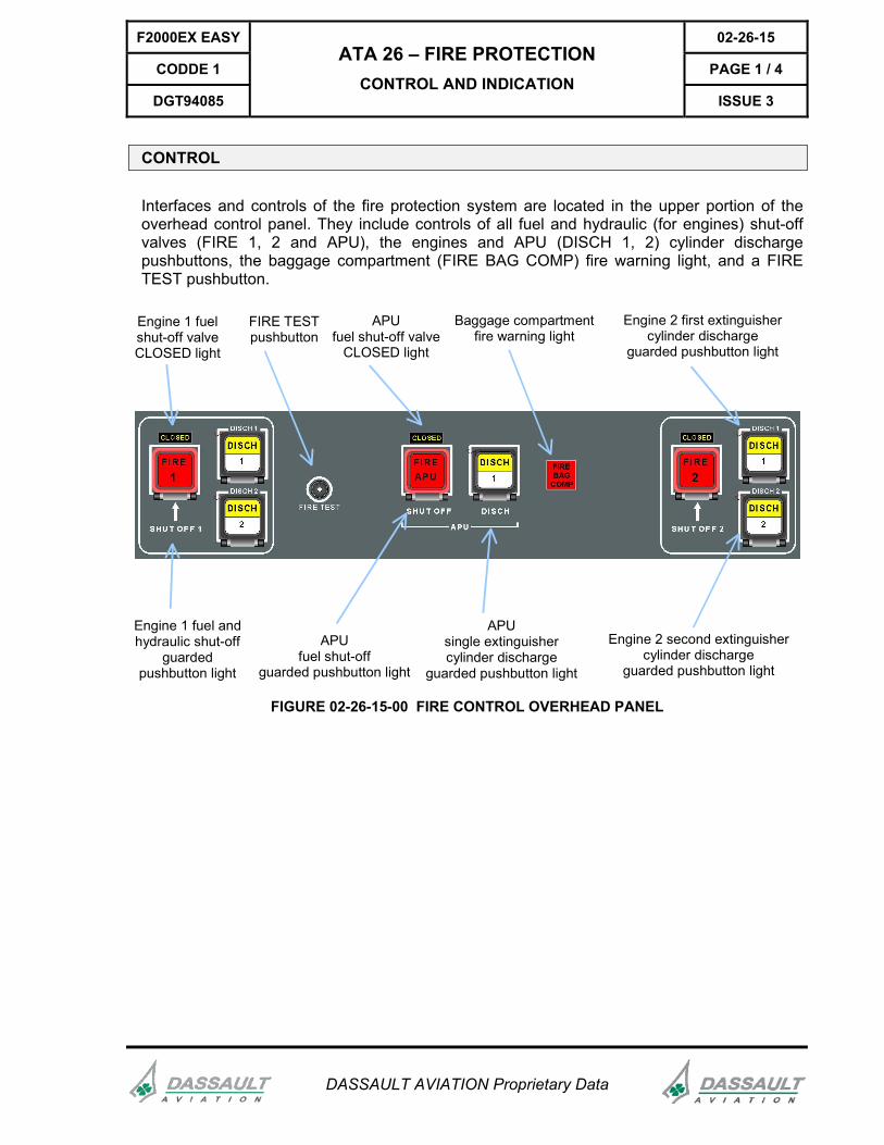
Interfaces and controls of the fire protection system are located in the upper portion of the overhead control panel. They include controls of all fuel and hydraulic (for engines) shut-off valves (FIRE 1, 2 and APU), the engines and APU (DISCH 1, 2) cylinder discharge pushbuttons, the baggage compartment (FIRE BAG COMP) fire warning light, and a FIRE TEST pushbutton.
Engine 1 fuelshut-off valveCLOSED light
Engine 1 fuel andhydraulic shut-off
guardedpushbutton light
APUfuel shut-off valve
CLOSED light
Engine 2 first extinguishercylinder discharge
guarded pushbutton light
APUsingle extinguishercylinder discharge
guarded pushbutton light
Engine 2 second extinguishercylinder discharge
guarded pushbutton light
Baggage compartmentfire warning light
FIRE TESTpushbutton
APUfuel shut-off
guarded pushbutton light
FIGURE 02-26-15-00 FIRE CONTROL OVERHEAD PANEL
02-26-15 F2000EX EASY
PAGE 2 / 4 CODDE 1
ISSUE 3
ATA 26 – FIRE PROTECTION CONTROL AND INDICATION
DGT94085
DASSAULT AVIATION Proprietary Data
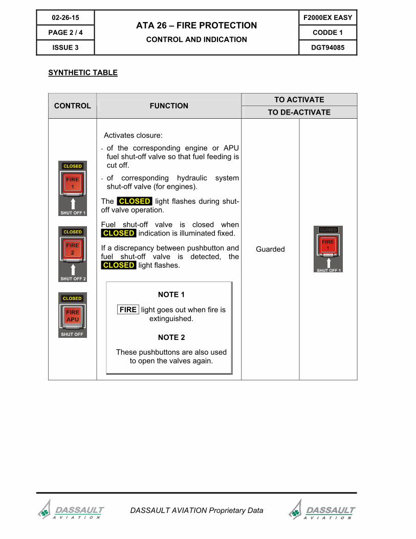
SYNTHETIC TABLE
TO ACTIVATE CONTROL FUNCTION
TO DE-ACTIVATE
Activates closure:
- of the corresponding engine or APU fuel shut-off valve so that fuel feeding is cut off.
- of corresponding hydraulic system shut-off valve (for engines).
The CLOSED light flashes during shut-off valve operation.
Fuel shut-off valve is closed when CLOSED indication is illuminated fixed.
If a discrepancy between pushbutton and fuel shut-off valve is detected, the CLOSED light flashes.
NOTE 1
FIRE light goes out when fire is extinguished.
NOTE 2
These pushbuttons are also used to open the valves again.
Guarded
F2000EX EASY 02-26-15
CODDE 1 PAGE 3 / 4
DGT94085
ATA 26 – FIRE PROTECTION CONTROL AND INDICATION
ISSUE 3
DASSAULT AVIATION Proprietary Data
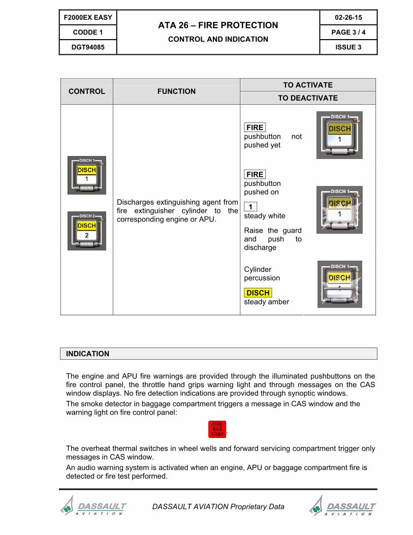
TO ACTIVATE CONTROL FUNCTION
TO DEACTIVATE
FIRE pushbutton not pushed yet
FIRE pushbutton pushed on
1 steady white
Raise the guard and push to discharge
Discharges extinguishing agent from fire extinguisher cylinder to the corresponding engine or APU.
Cylinder percussion
DISCH steady amber
INDICATION
The engine and APU fire warnings are provided through the illuminated pushbuttons on the fire control panel, the throttle hand grips warning light and through messages on the CAS window displays. No fire detection indications are provided through synoptic windows. The smoke detector in baggage compartment triggers a message in CAS window and the warning light on fire control panel:
.
The overheat thermal switches in wheel wells and forward servicing compartment trigger only messages in CAS window. An audio warning system is activated when an engine, APU or baggage compartment fire is detected or fire test performed.

02-26-15 F2000EX EASY
PAGE 4 / 4 CODDE 1
ISSUE 3
ATA 26 – FIRE PROTECTION CONTROL AND INDICATION
DGT94085
DASSAULT AVIATION Proprietary Data
INTENTIONALLY LEFT BLANK
F2000EX EASY 02-26-20
CODDE 1 PAGE 1 / 2
DGT94085
ATA 26 – FIRE PROTECTION SYSTEM PROTECTION
ISSUE 3
DASSAULT AVIATION Proprietary Data
INTRODUCTION
The fire control panel is physically and electrically segregated from the other systems located on the overhead control panel. (Except for the illuminated white markings on the front panel).
CIRCUIT BREAKERS
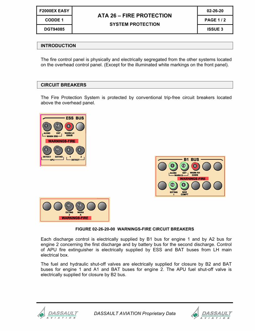
The Fire Protection System is protected by conventional trip-free circuit breakers located above the overhead panel.
FIGURE 02-26-20-00 WARNINGS-FIRE CIRCUIT BREAKERS
Each discharge control is electrically supplied by B1 bus for engine 1 and by A2 bus for engine 2 concerning the first discharge and by battery bus for the second discharge. Control of APU fire extinguisher is electrically supplied by ESS and BAT buses from LH main electrical box.
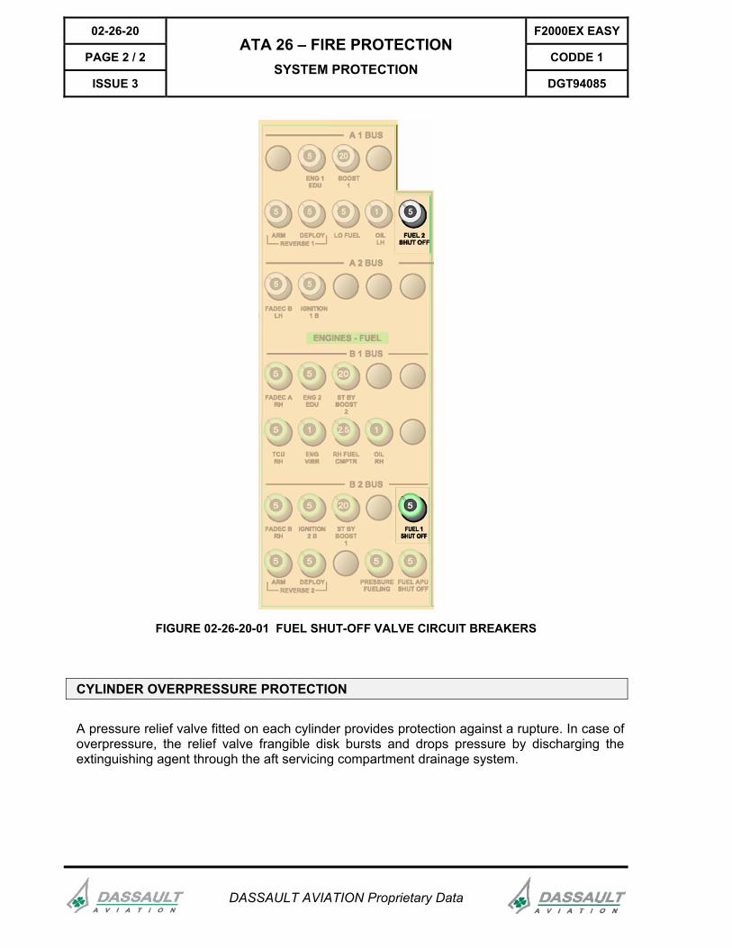
The fuel and hydraulic shut-off valves are electrically supplied for closure by B2 and BAT buses for engine 1 and A1 and BAT buses for engine 2. The APU fuel shut-off valve is electrically supplied for closure by B2 bus.
02-26-20 F2000EX EASY
PAGE 2 / 2 CODDE 1
ISSUE 3
ATA 26 – FIRE PROTECTION SYSTEM PROTECTION
DGT94085
DASSAULT AVIATION Proprietary Data
FIGURE 02-26-20-01 FUEL SHUT-OFF VALVE CIRCUIT BREAKERS
CYLINDER OVERPRESSURE PROTECTION
A pressure relief valve fitted on each cylinder provides protection against a rupture. In case of overpressure, the relief valve frangible disk bursts and drops pressure by discharging the extinguishing agent through the aft servicing compartment drainage system.
F2000EX EASY 02-26-25
CODDE 1 PAGE 1 / 4
DGT94085
ATA 26 – FIRE PROTECTION NORMAL OPERATION
ISSUE 3
DASSAULT AVIATION Proprietary Data
INTRODUCTION
In the following, typical ground and in-flight situations have been selected to help the crew to understand the symbols and the logic of the fire control panel and displays.
ENGINE AND APU FIRE EXTINGUISHING
ACTION RESULT
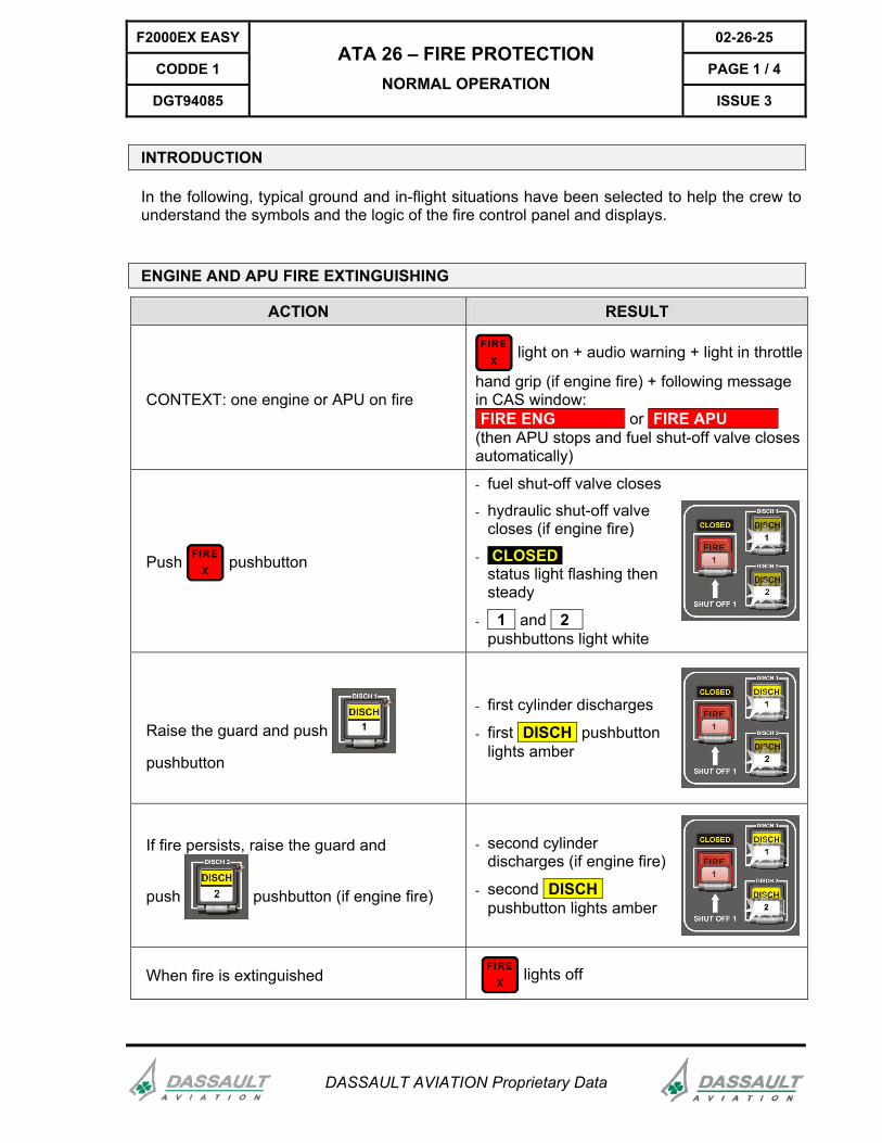
CONTEXT: one engine or APU on fire
light on + audio warning + light in throttle
hand grip (if engine fire) + following message in CAS window: FIRE ENG or FIRE APU (then APU stops and fuel shut-off valve closes automatically)
Push pushbutton
- fuel shut-off valve closes
- hydraulic shut-off valve closes (if engine fire)
- CLOSED status light flashing then steady
- 1 and 2 I pushbuttons light white
Raise the guard and push
pushbutton
- first cylinder discharges
- first DISCH pushbutton lights amber
If fire persists, raise the guard and
push pushbutton (if engine fire)
- second cylinder discharges (if engine fire)
- second DISCH pushbutton lights amber
When fire is extinguished lights off
02-26-25 F2000EX EASY
PAGE 2 / 4 CODDE 1
ISSUE 3
ATA 26 – FIRE PROTECTION NORMAL OPERATION
DGT94085
DASSAULT AVIATION Proprietary Data
Failure of the fire detection system is indicated by ENG .. FIRE DETECT FAIL or APU FIRE DETECT FAIL CAS message.
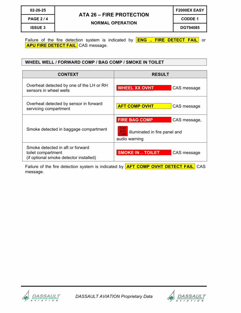
WHEEL WELL / FORWARD COMP / BAG COMP / SMOKE IN TOILET
CONTEXT RESULT
Overheat detected by one of the LH or RH sensors in wheel wells WHEEL XX OVHT CAS message
Overheat detected by sensor in forward servicing compartment AFT COMP OVHT CAS message
Smoke detected in baggage compartment
FIRE BAG COMP CAS message,
illuminated in fire panel and audio warning
Smoke detected in aft or forward toilet compartment (if optional smoke detector installed)
SMOKE IN .. TOILET CAS message
Failure of the fire detection system is indicated by AFT COMP OVHT DETECT FAIL CAS message.
F2000EX EASY 02-26-25
CODDE 1 PAGE 3 / 4
DGT94085
ATA 26 – FIRE PROTECTION NORMAL OPERATION
ISSUE 3
DASSAULT AVIATION Proprietary Data
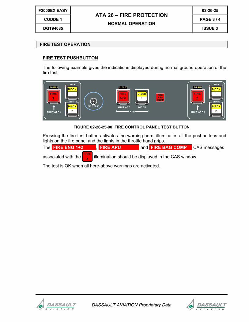
FIRE TEST OPERATION
FIRE TEST PUSHBUTTON
The following example gives the indications displayed during normal ground operation of the fire test.
FIGURE 02-26-25-00 FIRE CONTROL PANEL TEST BUTTON
Pressing the fire test button activates the warning horn, illuminates all the pushbuttons and lights on the fire panel and the lights in the throttle hand grips. The FIRE ENG 1+2 , FIRE APU and FIRE BAG COMP CAS messages
associated with the illumination should be displayed in the CAS window.
The test is OK when all here-above warnings are activated.
02-26-25 F2000EX EASY
PAGE 4 / 4 CODDE 1
ISSUE 3
ATA 26 – FIRE PROTECTION NORMAL OPERATION
DGT94085
DASSAULT AVIATION Proprietary Data
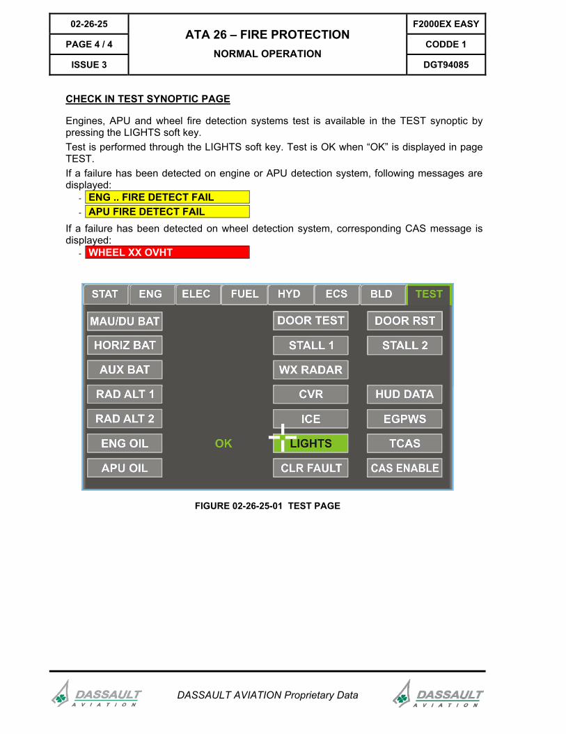
CHECK IN TEST SYNOPTIC PAGE
Engines, APU and wheel fire detection systems test is available in the TEST synoptic by pressing the LIGHTS soft key. Test is performed through the LIGHTS soft key. Test is OK when “OK” is displayed in page TEST. If a failure has been detected on engine or APU detection system, following messages are displayed:
- ENG .. FIRE DETECT FAIL - APU FIRE DETECT FAIL
If a failure has been detected on wheel detection system, corresponding CAS message is displayed:
- WHEEL XX OVHT
FIGURE 02-26-25-01 TEST PAGE
F2000EX EASY 02-26-30
CODDE 1 PAGE 1 / 2
DGT94085
ATA 26 – FIRE PROTECTION ABNORMAL OPERATION
ISSUE 3
DASSAULT AVIATION Proprietary Data
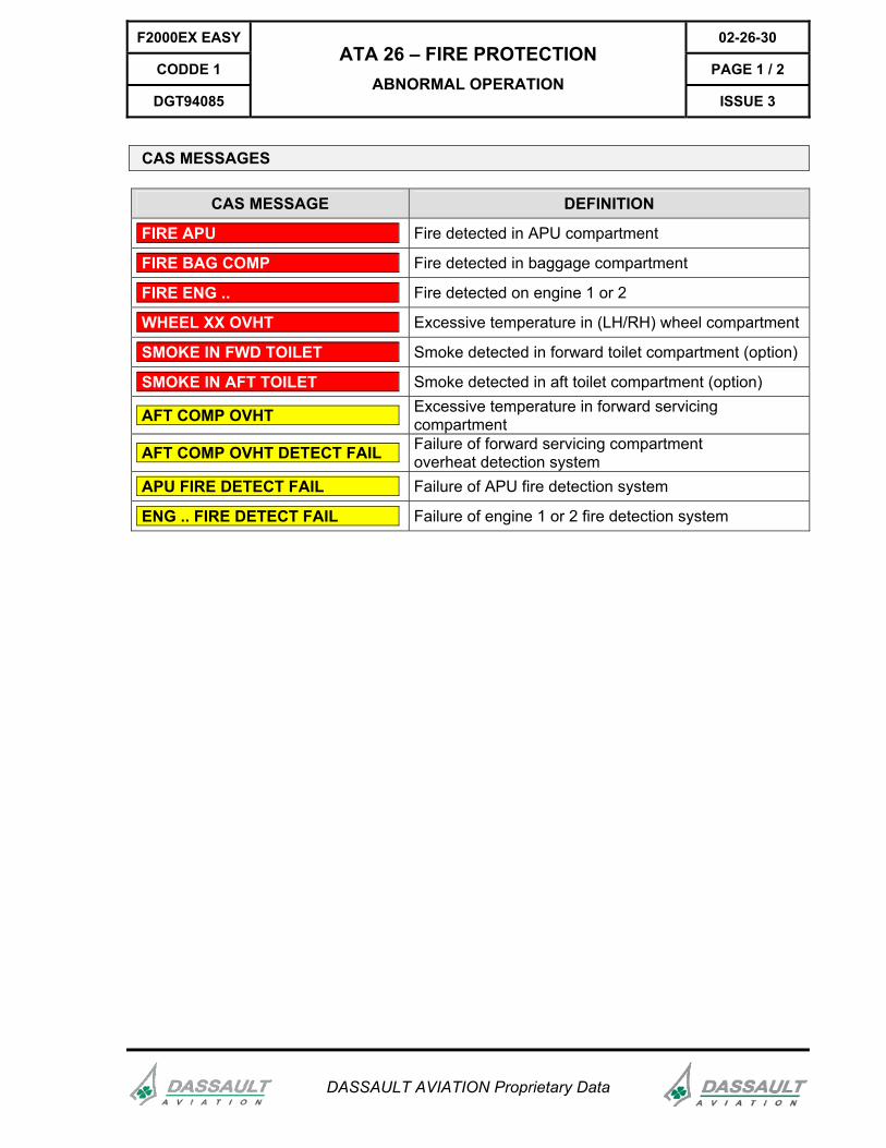
CAS MESSAGES
CAS MESSAGE DEFINITION
FIRE APU Fire detected in APU compartment
FIRE BAG COMP Fire detected in baggage compartment
FIRE ENG .. Fire detected on engine 1 or 2
WHEEL XX OVHT Excessive temperature in (LH/RH) wheel compartment
SMOKE IN FWD TOILET Smoke detected in forward toilet compartment (option)
SMOKE IN AFT TOILET Smoke detected in aft toilet compartment (option)
AFT COMP OVHT Excessive temperature in forward servicing compartment
AFT COMP OVHT DETECT FAIL Failure of forward servicing compartment overheat detection system
APU FIRE DETECT FAIL Failure of APU fire detection system
ENG .. FIRE DETECT FAIL Failure of engine 1 or 2 fire detection system
02-26-30 F2000EX EASY
PAGE 2 / 2 CODDE 1
ISSUE 3
ATA 26 – FIRE PROTECTION ABNORMAL OPERATION
DGT94085
DASSAULT AVIATION Proprietary Data
INTENTIONALLY LEFT BLANK