exxonmobil nox emission reduction opportunities/challenges · exxonmobil nox emission reduction...
TRANSCRIPT
ExxonMobil NOx Emission Reduction Opportunities/Challenges
Texas Technology ShowcaseMarch 17-19, 2003
Boyd HurstExxonMobil Research & Engineering Co
March 17, 2003 2
ExxonMobil NOx Emission Reduction
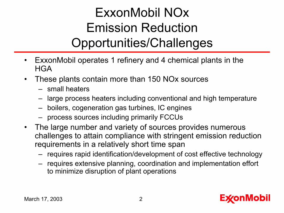
Opportunities/Challenges• ExxonMobil operates 1 refinery and 4 chemical plants in the
HGA• These plants contain more than 150 NOx sources
– small heaters– large process heaters including conventional and high temperature– boilers, cogeneration gas turbines, IC engines– process sources including primarily FCCUs
• The large number and variety of sources provides numerous challenges to attain compliance with stringent emission reduction requirements in a relatively short time span– requires rapid identification/development of cost effective technology– requires extensive planning, coordination and implementation effort
to minimize disruption of plant operations
March 17, 2003 3
Large Variety of NOx Sources
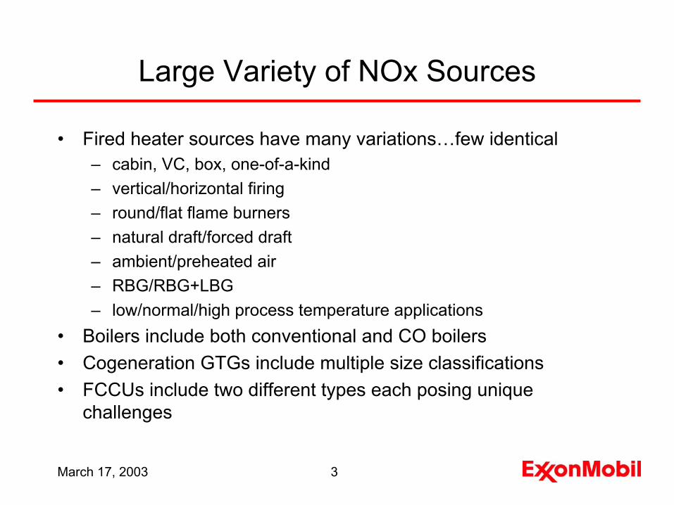
• Fired heater sources have many variations…few identical– cabin, VC, box, one-of-a-kind– vertical/horizontal firing– round/flat flame burners– natural draft/forced draft– ambient/preheated air– RBG/RBG+LBG– low/normal/high process temperature applications
• Boilers include both conventional and CO boilers• Cogeneration GTGs include multiple size classifications• FCCUs include two different types each posing unique
challenges
March 17, 2003 4
Emissions and Equipment Demographics
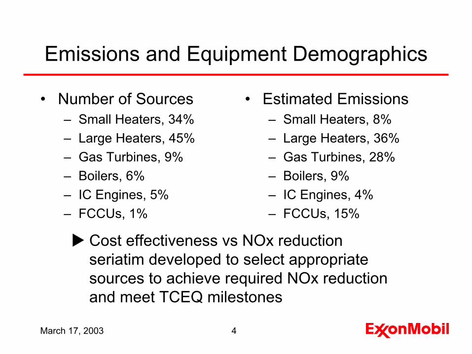
• Number of Sources– Small Heaters, 34% – Large Heaters, 45%– Gas Turbines, 9%– Boilers, 6%– IC Engines, 5%– FCCUs, 1%
• Estimated Emissions– Small Heaters, 8%– Large Heaters, 36%– Gas Turbines, 28%– Boilers, 9%– IC Engines, 4%– FCCUs, 15%
Cost effectiveness vs NOx reduction seriatim developed to select appropriate sources to achieve required NOx reduction and meet TCEQ milestones
March 17, 2003 5
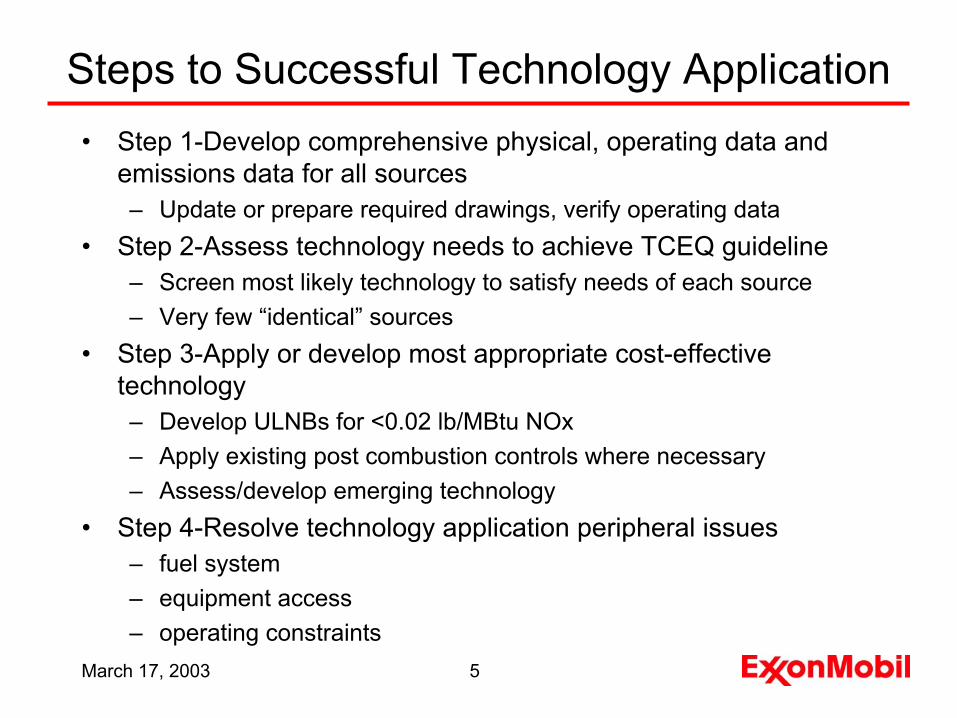
Steps to Successful Technology Application• Step 1-Develop comprehensive physical, operating data and
emissions data for all sources– Update or prepare required drawings, verify operating data
• Step 2-Assess technology needs to achieve TCEQ guideline– Screen most likely technology to satisfy needs of each source– Very few “identical” sources
• Step 3-Apply or develop most appropriate cost-effective technology– Develop ULNBs for <0.02 lb/MBtu NOx– Apply existing post combustion controls where necessary– Assess/develop emerging technology
• Step 4-Resolve technology application peripheral issues– fuel system– equipment access– operating constraints
March 17, 2003 6
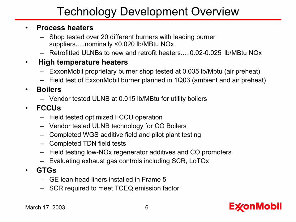
Technology Development Overview• Process heaters
– Shop tested over 20 different burners with leading burner suppliers.....nominally <0.020 lb/MBtu NOx
– Retrofitted ULNBs to new and retrofit heaters.....0.02-0.025 lb/MBtu NOx• High temperature heaters
– ExxonMobil proprietary burner shop tested at 0.035 lb/Mbtu (air preheat)– Field test of ExxonMobil burner planned in 1Q03 (ambient and air preheat)
• Boilers– Vendor tested ULNB at 0.015 lb/MBtu for utility boilers
• FCCUs– Field tested optimized FCCU operation– Vendor tested ULNB technology for CO Boilers– Completed WGS additive field and pilot plant testing– Completed TDN field tests– Field testing low-NOx regenerator additives and CO promoters– Evaluating exhaust gas controls including SCR, LoTOx
• GTGs– GE lean head liners installed in Frame 5– SCR required to meet TCEQ emission factor
March 17, 2003 7
00.020.040.060.08
0.10.120.140.16
lb/MBtu/hr
Heater 1 Heater 2 Heater 3 Heater 4
BaseShopField
Fired Heater Ultra Low NOx Burners
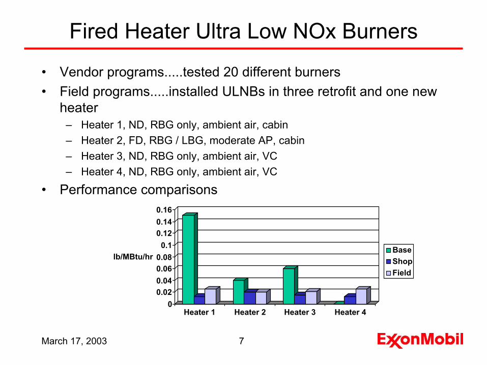
• Vendor programs.....tested 20 different burners• Field programs.....installed ULNBs in three retrofit and one new
heater– Heater 1, ND, RBG only, ambient air, cabin– Heater 2, FD, RBG / LBG, moderate AP, cabin– Heater 3, ND, RBG only, ambient air, VC– Heater 4, ND, RBG only, ambient air, VC
• Performance comparisons
March 17, 2003 8
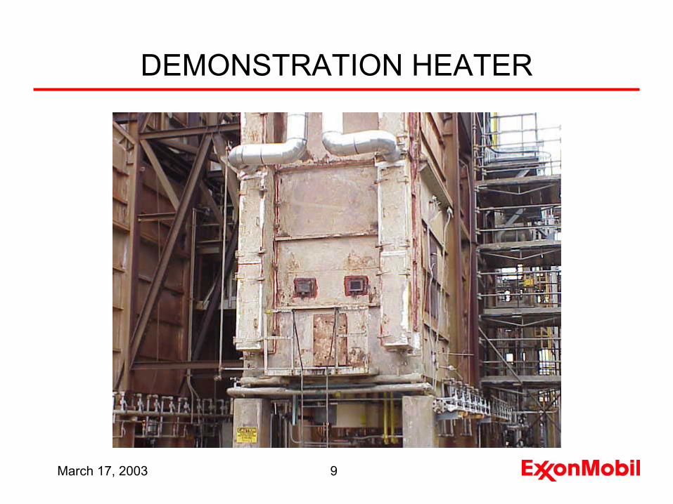
Refinery Demonstration Heater
• Demonstration conducted in association with consortium headed by DOE and ExxonMobil was a member
• Demonstration furnace was an atmospheric pipestill furnace atExxonMobil’s Baytown Texas refinery – horizontal tube cabin configuration– 140 MBtu/hr maximum firing rate– fuel gas composition varies from high methane to high hydrogen
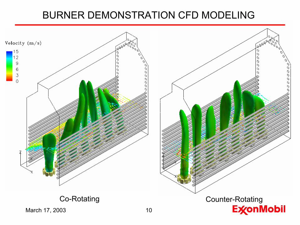
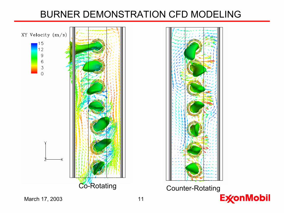
• A computational fluid dynamics ( CFD) model was utilized to predict radiant section performance and thereby identify potential problems– Flow patterns– Flame geometry
March 17, 2003 9
DEMONSTRATION HEATER
March 17, 2003 10
Co-Rotating Counter-Rotating
BURNER DEMONSTRATION CFD MODELING
March 17, 2003 11
Co-Rotating Counter-Rotating
BURNER DEMONSTRATION CFD MODELING
March 17, 2003 12
IMPLEMENTATION/STARTUP SUCCESSFUL
• A set of 14 field test burners were installed for the retrofit demonstration replacing 18 original burners
• The fired heater was started up in May 2001.– Flame geometry and flow patterns are consistent with the CFD
predictions– Heat Flux profile meets specifications.– Burner stability good when fuel composition is within specifications;
however pulsation experienced when methane content exceeds 85%.
– Initial NOx levels higher than anticipated at 0.030 lb/MBtu – A new flame stabilizer and gas tips were developed to enhance
stability and lower NOx to ~0.025 lb/MBtu
March 17, 2003 13
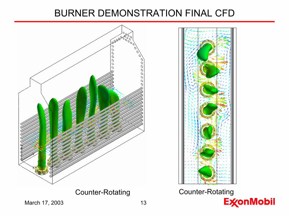
BURNER DEMONSTRATION FINAL CFD
Counter-RotatingCounter-Rotating

March 17, 2003 14
BURNER FLAMES MATCH CFD PREDICTION
March 17, 2003 15
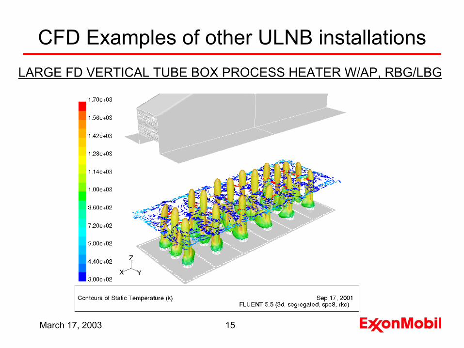
CFD Examples of other ULNB installationsLARGE FD VERTICAL TUBE BOX PROCESS HEATER W/AP, RBG/LBG
March 17, 2003 16
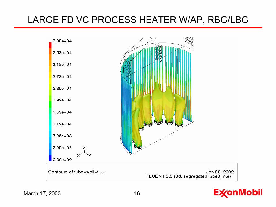
LARGE FD VC PROCESS HEATER W/AP, RBG/LBG
March 17, 2003 17
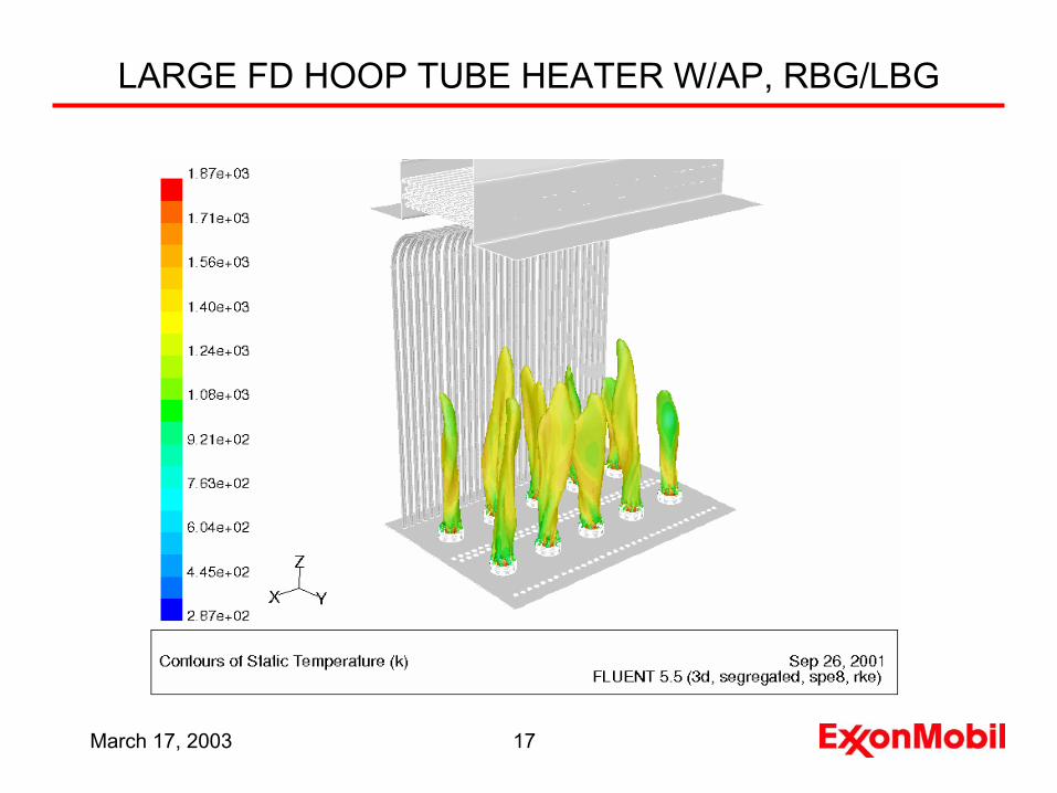
LARGE FD HOOP TUBE HEATER W/AP, RBG/LBG
March 17, 2003 18
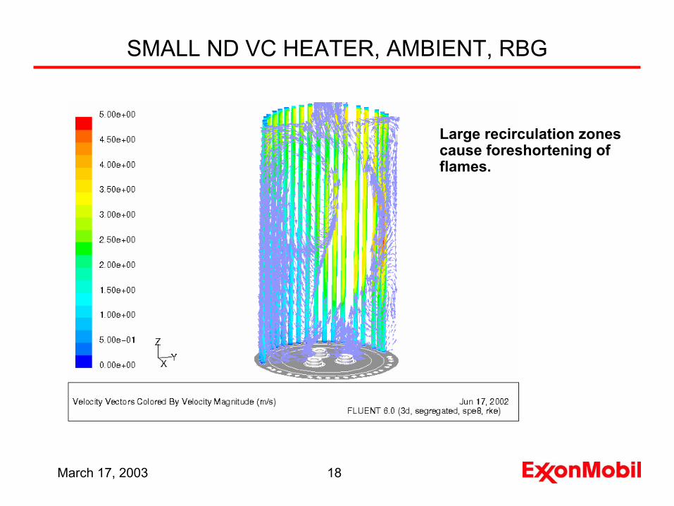
SMALL ND VC HEATER, AMBIENT, RBG
Large recirculation zonescause foreshortening of flames.
March 17, 2003 19
0
0.02
0.04
0.06
0.08
0.1
lb NOx/MBtu
w/o Air Preheat w/ Air Preheat
BaseShopEst. Field
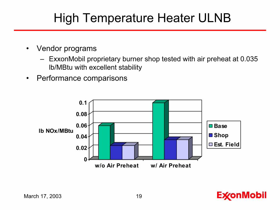
• Vendor programs– ExxonMobil proprietary burner shop tested with air preheat at 0.035
lb/MBtu with excellent stability• Performance comparisons
High Temperature Heater ULNB
March 17, 2003 20
Power Boilers
• Power boilers– Boilers are tangential fired (two levels), moderate AP, RBG and
waste fuel– Design conditions:
• steam flow-320,000 lb/hr• pressure-1500 psig• temperature-915 F
• Burners– Include reconfigured windbox/burner gun location– Burner guns designed for “attached” flames– Flue gas recirculation 15%-25%– Air distribution improved to each corner and within each windbox to
enable low excess O2 operation
March 17, 2003 21
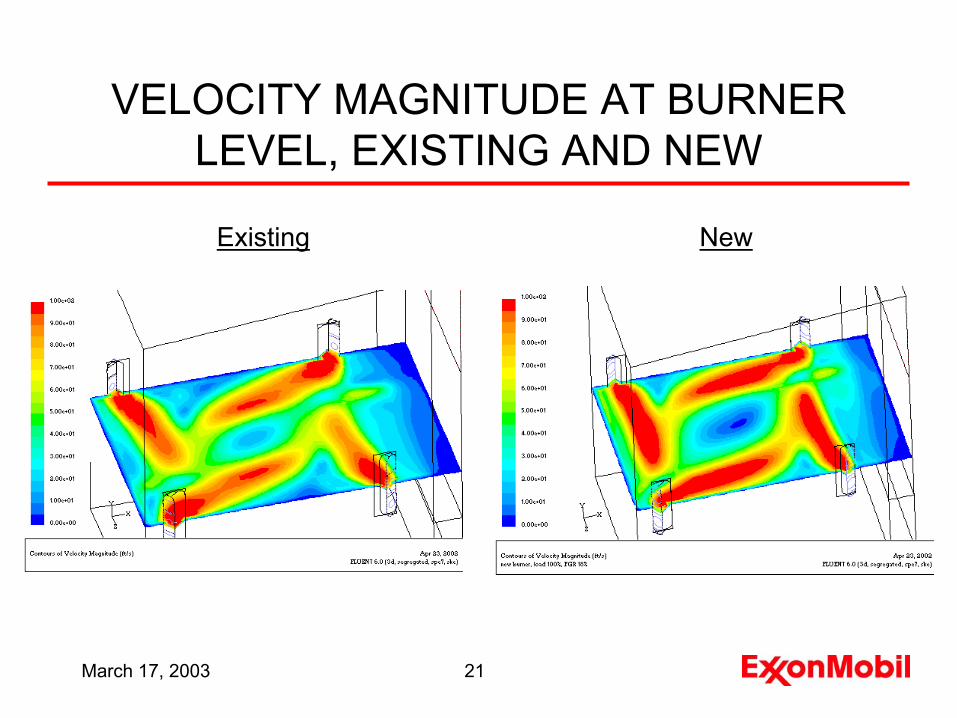
VELOCITY MAGNITUDE AT BURNER LEVEL, EXISTING AND NEW
Existing New
March 17, 2003 22
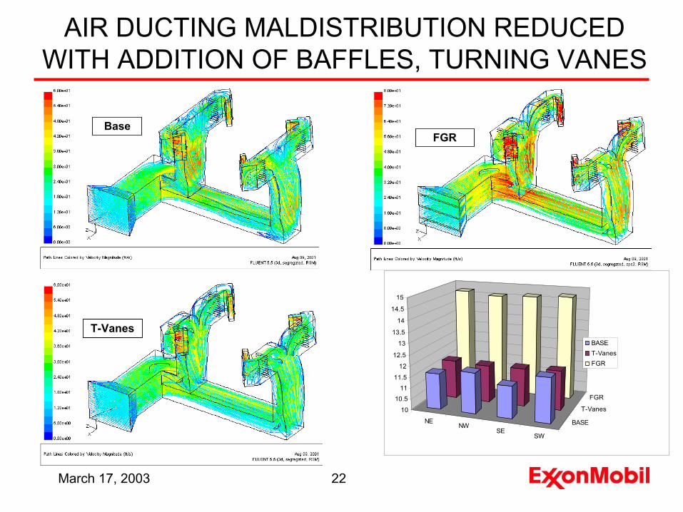
AIR DUCTING MALDISTRIBUTION REDUCED WITH ADDITION OF BAFFLES, TURNING VANES
FGR
T-Vanes
Base
NENW
SESW
BASE
T-Vanes
FGR
10
10.511
11.5
12
12.5
13
13.5
14
14.5
15
BASET-VanesFGR
March 17, 2003 23
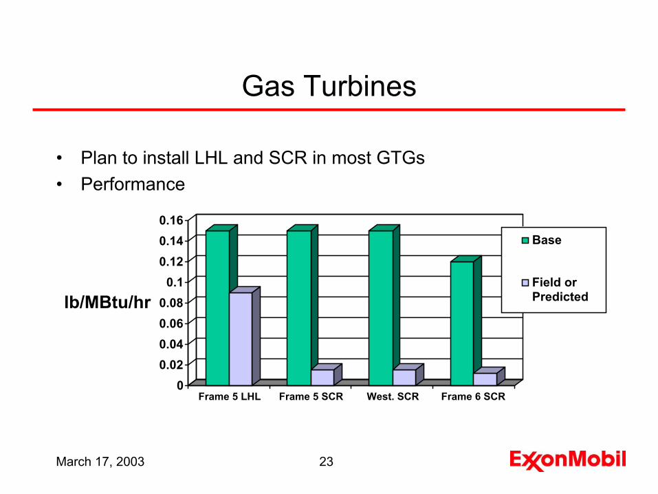
Gas Turbines
• Plan to install LHL and SCR in most GTGs• Performance
00.020.040.060.08
0.10.120.140.16
lb/MBtu/hr
Frame 5 LHL Frame 5 SCR West. SCR Frame 6 SCR
Base
Field orPredicted
March 17, 2003 24
FCCU NOx Reduction• Involves multiple technologies including operational changes,
combustion and post combustion techniques• Strategy includes
– utilization of existing equipment as reaction chamber– multiple reduction steps each with different technology– minimization of overall cost through optimization of investment and
operating cost• Technologies under consideration include
– optimized low NOx operation – low NOx CO promoter and/or low NOx additive– regenerator overhead line TDN– retrofit CO boilers with LNBs– WGS additive– SCR– LoTOx
March 17, 2003 25
CO Boiler LNBs
• Includes two types of boilers– tangential fired (2), SG 501 A/B– opposed wall fired, SG 501 C
• Opposed wall fired boiler has twice capacity of each tangential fired boiler, receives one-half of regenerator overhead off-gas
• Boilers have capability of maintaining capacity with fuel gas firing alone (no regenerator off-gas)
• Combined stream from 3 boilers is sent to a WGS
March 17, 2003 26
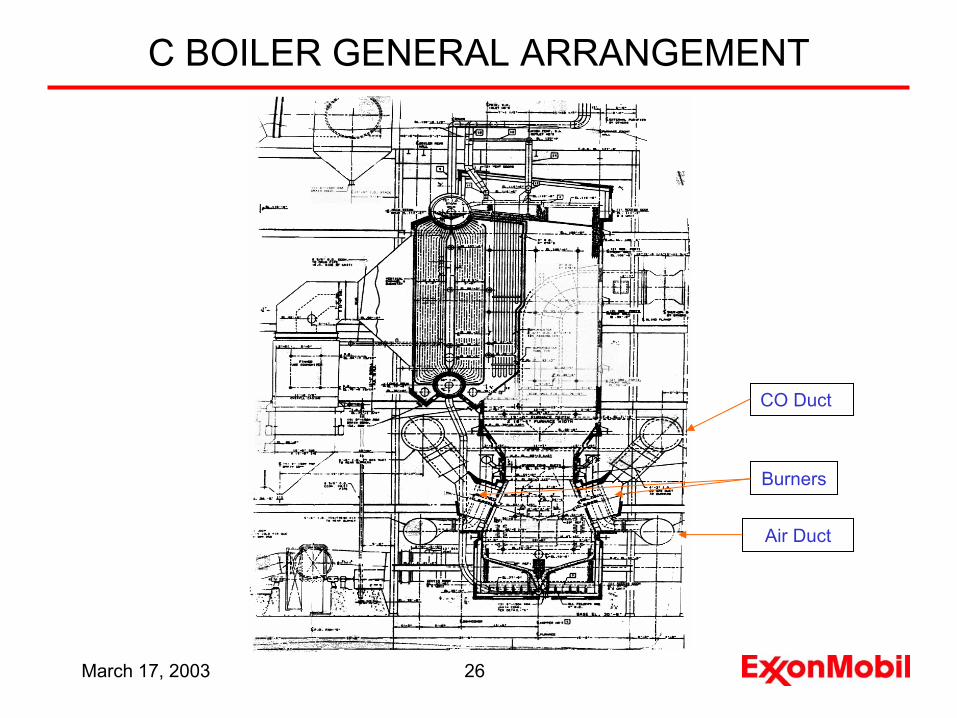
C BOILER GENERAL ARRANGEMENT
Burners
CO Duct
Air Duct

March 17, 2003 27
NEW BURNER FOR C BOILER
Legend:Red = Burner GunBlue = PilotYellow = Scanner
Burner Plenum Insert
Burner Plenum Shell
March 17, 2003 28
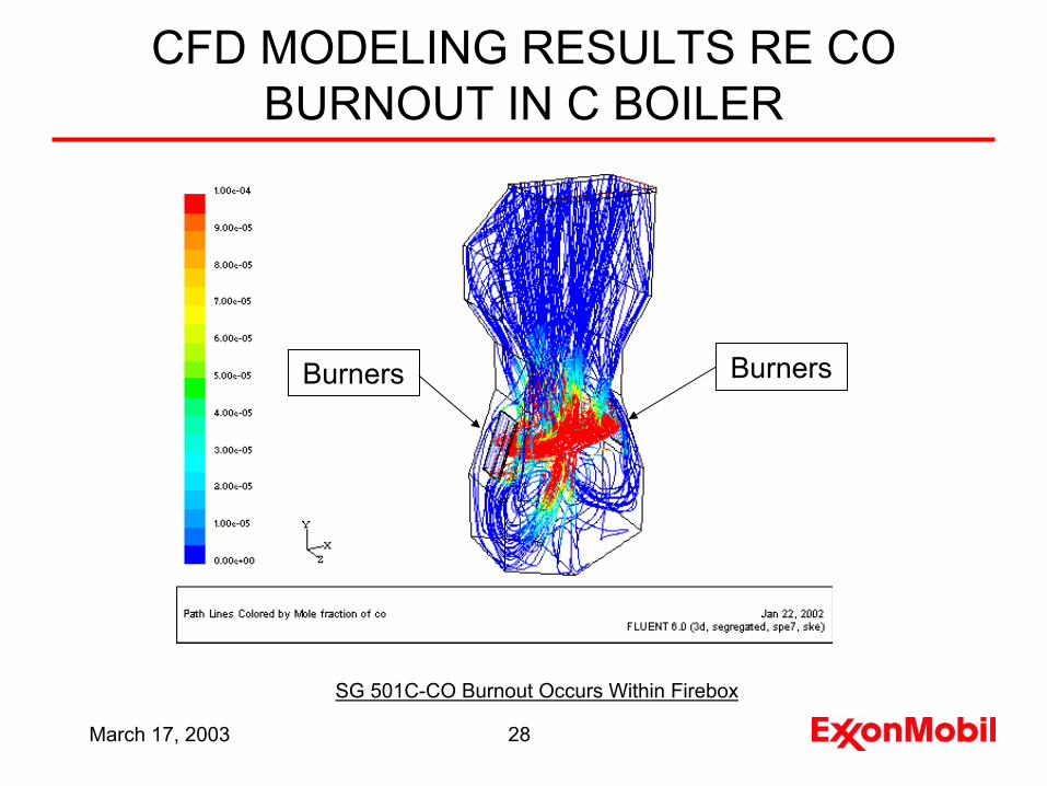
CFD MODELING RESULTS RE CO BURNOUT IN C BOILER
SG 501C-CO Burnout Occurs Within Firebox
BurnersBurners
March 17, 2003 29
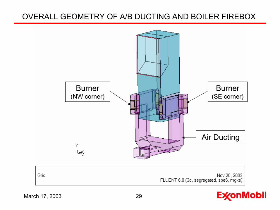
OVERALL GEOMETRY OF A/B DUCTING AND BOILER FIREBOX
Burner(SE corner)
Burner(NW corner)
Air Ducting
March 17, 2003 30
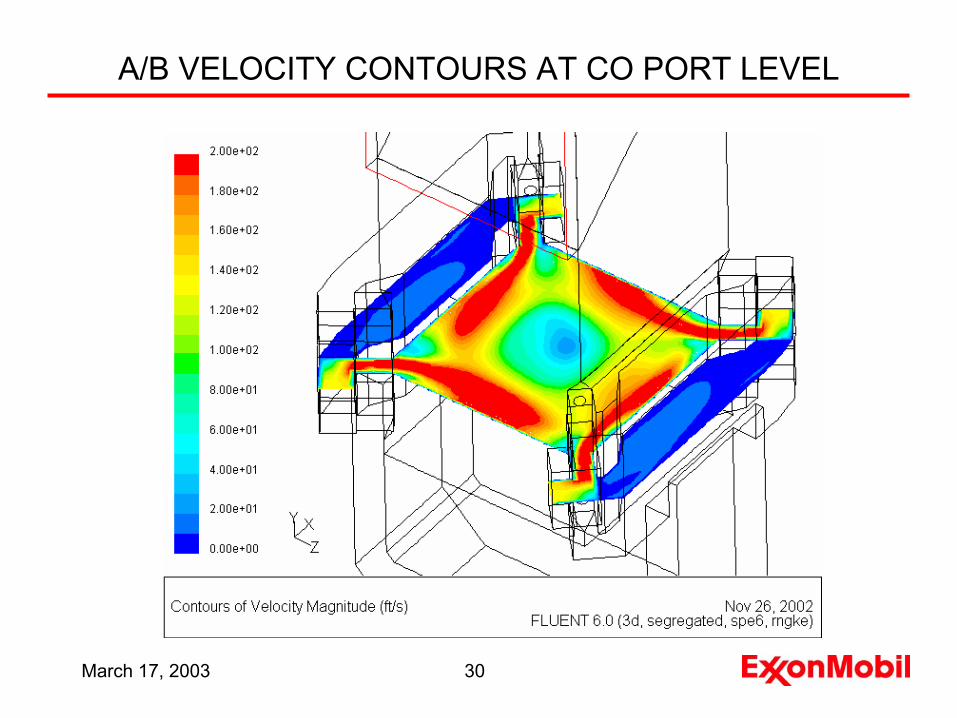
A/B VELOCITY CONTOURS AT CO PORT LEVEL
March 17, 2003 31
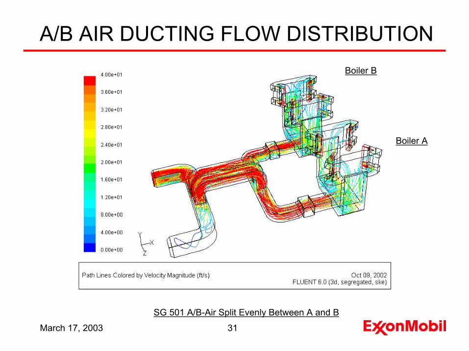
A/B AIR DUCTING FLOW DISTRIBUTION
SG 501 A/B-Air Split Evenly Between A and B
Boiler B
Boiler A

March 17, 2003 32
A/B COMBUSTION AIR DISTRIBUTION IN WINDBOXES
SG 501A/B-Windbox Requires Turning Vanes To Equalize Air Distribution
March 17, 2003 33
Conclusions
• Goal is to meet the HGA Ozone SIP in the most economical way while maintaining throughput and service factor
• Challenges/opportunities are numerous and varied requiring application of known technology as well as rapid development of new technology
• Technology development must be progressed simultaneous with implementation plans
• Investment cost can be minimized by judicious selection of sources/technologies
• ExxonMobil is on target to comply with TCEQ requirements

Questions?