exposed-aggregate finishes for flatwork - ccaa documents/ccaa... · exposed-aggregate finishes for...
TRANSCRIPT
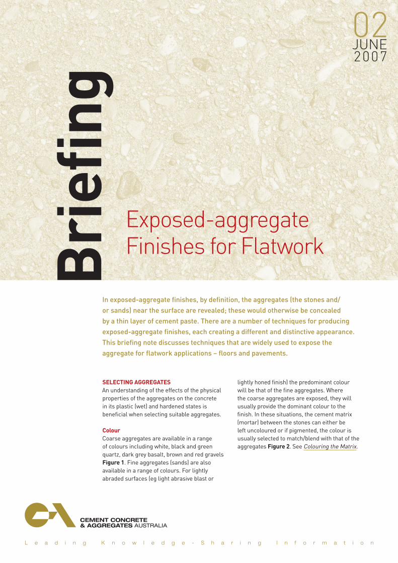
Exposed-aggregate Finishes for Flatwork
SELECTING AGGREGATESAn understanding of the effects of the physical properties of the aggregates on the concrete in its plastic (wet) and hardened states is beneficial when selecting suitable aggregates.
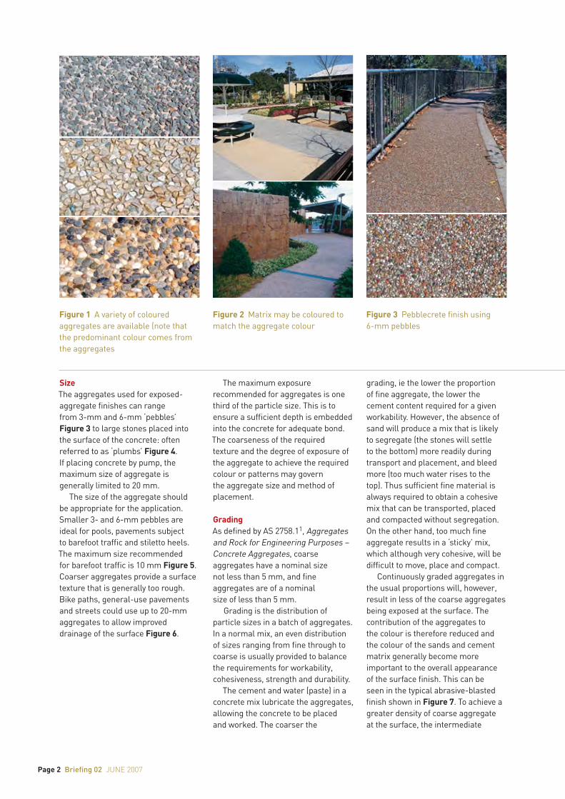
Colour Coarse aggregates are available in a range of colours including white, black and green quartz, dark grey basalt, brown and red gravels Figure 1. Fine aggregates (sands) are also available in a range of colours. For lightly abraded surfaces (eg light abrasive blast or
lightly honed finish) the predominant colour will be that of the fine aggregates. Where the coarse aggregates are exposed, they will usually provide the dominant colour to the finish. In these situations, the cement matrix (mortar) between the stones can either be left uncoloured or if pigmented, the colour is usually selected to match/blend with that of the aggregates Figure 2. See Colouring the Matrix.
Bri
efing
02june 2007
In exposed-aggregate finishes, by definition, the aggregates (the stones and/
or sands) near the surface are revealed; these would otherwise be concealed
by a thin layer of cement paste. There are a number of techniques for producing
exposed-aggregate finishes, each creating a different and distinctive appearance.
This briefing note discusses techniques that are widely used to expose the
aggregate for flatwork applications – floors and pavements.
Page 2 Briefing 02 june 2007
SizeThe aggregates used for exposed-aggregate finishes can range from 3-mm and 6-mm ‘pebbles’ Figure 3 to large stones placed into the surface of the concrete: often referred to as ‘plumbs’ Figure 4. If placing concrete by pump, the maximum size of aggregate is generally limited to 20 mm.
The size of the aggregate should be appropriate for the application. Smaller 3- and 6-mm pebbles are ideal for pools, pavements subject to barefoot traffic and stiletto heels. The maximum size recommended for barefoot traffic is 10 mm Figure 5. Coarser aggregates provide a surface texture that is generally too rough. Bike paths, general-use pavements and streets could use up to 20-mm aggregates to allow improved drainage of the surface Figure 6.
The maximum exposure recommended for aggregates is one third of the particle size. This is to ensure a sufficient depth is embedded into the concrete for adequate bond. The coarseness of the required texture and the degree of exposure of the aggregate to achieve the required colour or patterns may govern the aggregate size and method of placement.
GradingAs defined by AS 2758.11, Aggregates and Rock for Engineering Purposes – Concrete Aggregates, coarse aggregates have a nominal size not less than 5 mm, and fine aggregates are of a nominal size of less than 5 mm.
Grading is the distribution of particle sizes in a batch of aggregates. In a normal mix, an even distribution of sizes ranging from fine through to coarse is usually provided to balance the requirements for workability, cohesiveness, strength and durability.
The cement and water (paste) in a concrete mix lubricate the aggregates, allowing the concrete to be placed and worked. The coarser the
grading, ie the lower the proportion of fine aggregate, the lower the cement content required for a given workability. However, the absence of sand will produce a mix that is likely to segregate (the stones will settle to the bottom) more readily during transport and placement, and bleed more (too much water rises to the top). Thus sufficient fine material is always required to obtain a cohesive mix that can be transported, placed and compacted without segregation. On the other hand, too much fine aggregate results in a ‘sticky’ mix, which although very cohesive, will be difficult to move, place and compact.
Continuously graded aggregates in the usual proportions will, however, result in less of the coarse aggregates being exposed at the surface. The contribution of the aggregates to the colour is therefore reduced and the colour of the sands and cement matrix generally become more important to the overall appearance of the surface finish. This can be seen in the typical abrasive-blasted finish shown in Figure 7. To achieve a greater density of coarse aggregate at the surface, the intermediate
Figure 1 A variety of coloured aggregates are available (note that the predominant colour comes from the aggregates
Figure 3 Pebblecrete finish using 6-mm pebbles
Figure 2 Matrix may be coloured to match the aggregate colour

Briefing 02 june 2007 Page 3
aggregate sizes are often omitted in what is called a gap-graded mix. With gap grading, a larger percentage of coarse aggregate and a small percentage of fine aggregate (sufficient for workability) are combined. If the fine aggregate contains a high proportion of larger particles, these may space the coarse aggregate stones further apart and result in a ‘patchy’ appearance Figure 8. To achieve a uniform aggregate density at the surface Figure 1, particularly with 7- to 10-mm stones, the fine aggregate should not contain a high proportion of particles around the maximum size of 5 mm.
ShapeThe shape of the aggregates will affect the workability of the fresh concrete and its strength when hardened. Smooth, rounded aggregates enhance the workability; however, rough cubical stones (generally crushed to size) produce optimum strength.
Flat and elongated aggregates, referred to as misshapen particles Figure 9, reduce workability and may also have an adverse affect on strength because of their tendency to selective orientation and bridging, resulting in air pockets. A good mix design will limit the percentage of these particles in accordance with AS 2758.1. If a flaky, elongated aggregate has been selected to feature, it would be advisable to consider using a topping mix or seeding the surface with the aggregate as described under Adding Aggregates.
Where barefoot traffic is anticipated, the use of rounded river gravel instead of a crushed and angular aggregate is recommended. Where the surface is honed to expose the aggregate, the shape is irrelevant as a smooth surface is produced.
Surface TextureSurface texture can be classified as glassy, smooth, granular, rough, crystalline or honeycombed. For exposed aggregate surfaces, the surface texture or micro-texture of the aggregates will influence the slip and skid resistance of the surface. Glassy and smooth aggregates may not be suitable for sloping paths and driveways, or those in exterior environments that can be contaminated by water, thereby increasing the risk of slipping and skidding.
Figure 4 Large stones (‘plumbs’) set into concrete surface as traffic-control device
Figure 6 20-mm basalt and white quartz aggregates used for roadway
Figure 5 Aggregates for barefoot traffic

Page 4 Briefing 02 june 2007
DurabilityIssues that are particularly important in relation to the durability of exposed aggregate concrete include resistance to external abrasion and, for honed finishes, the strength of the concrete.
External abrasion can result from poor practices in the handling and mixing of aggregates, from harsh weather conditions or, in the case of a floor, path or road, trafficking. The greater the volume of traffic (vehicular or pedestrian) Figure 10, the more abrasion resistant the aggregate needs to be in order to continue providing satisfactory slip and skid resistance.
If aggregates are exposed by honing the surface, the abrasion resistance of the concrete is also important. A minimum strength of 32 MPa is recommended for honed finishes to ensure aggregate particles are not dislodged during the grinding process. This strength also provides satisfactory abrasion resistance for heavily trafficked pavements with traffic of 3 tonnes or more.
Special AggregatesSpecial aggregates that can be used to provide distinctive features within the finish include granite, marble and glass. Glass aggregates can be incorporated into concrete pavements and floors, but caution may need to be exercised in the application. They provide a depth to the finish by enabling people to see into the floor, provide a translucent feature, are available in a wide range of colours and increase the decorative options available Figures 11 and 12.
Some points to consider when using glass aggregates include:n They are exposed in the same way
as other aggregates. Common paving and floor applications involve honing the surface to provide a smooth finish and ensure edges are not exposed.
n They are normally crushed from thick pieces to obtain a cubical aggregate shape and the edges are dulled so that they are not sharp.
n Glass is generally seeded onto the surface to reduce material usage and cost2. This is also desirable because of the possibility of alkali silica reaction (ASR) which is discussed below).
n Glass is more brittle than stone so if honing the surface, start with a finer abrasive, ie 200 grit should be used, instead of the 60 to 100 commonly used for the initial grinding.
n The main concern with the use of glass in concrete is the possibility of a reaction between the alkalis in the concrete and the silica in the glass. The reaction produces an expansive gel that can cause cracking around the edges of the glass and possibly dislodge the aggregate from the concrete surface. For internal, dry applications the reaction can be minimised, if not prevented, by keeping the concrete dry. Thus it is important to maintain the surface sealer to prevent the ingress of any moisture. Glass content should be kept to a minimum. Also, the addition of fly ash and/or ground granulated blast furnace slag in the concrete mix can reduce the expansive reaction.
Figure 7 Exposed aggregates of ‘normal’ concrete mix
Figure 9 [a] Large river gravel (nominal 50-mm) containing misshapen particles seeded onto surface [b] 10-mm crushed aggregate mix
Figure 8 ‘Patchy’ appearance of 10-mm aggregate mix with high proportion of coarse particles in sand
Misshapen particle
a
b

Briefing 02 june 2007 Page 5
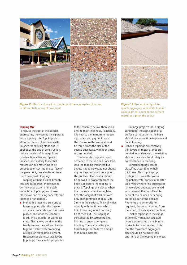
COLOURING THE MATRIXThe cement matrix (cement, water and sand) between the coarse aggregate particles can also be coloured in a number of ways: mineral oxide pigments, chemical stains, dyes, tints and coloured sealers. The colour is normally selected to match or complement the colour of the coarse aggregates Figure 13.
Pigments (typically 1–2%) can be integrally mixed into the concrete or mixed through a topping (see Adding Aggregates). Refer to Briefing 013 for more details about colouring concrete with mineral oxide pigments.
At the planning stage, suppliers of pigments can assist in determining the correct proportion of pigment to achieve the desired colour. Small test samples are essential in determining the final pigment and concentration to be used in order to achieve the desired appearance. Manufacturers may also provide a specification for their product and the method of dispersion through the concrete mix.
If the mix is not to be coloured with mineral oxides pigments, the fine aggregates and cement colour will largely determine the overall colour of the matrix. For large projects, ensure the contractor stockpiles sufficient quantities of both the coarse and fine aggregates for consistency of colour.
The colour of the cement will also affect the appearance. Cement falls broadly into three colour groups: white, off-white and grey, although variations of these colours are available, for example those that could be described as beige. Within each category, variations in the shade may also occur depending on the source of the material and manufacturing process. Variations are less noticeable with off-white and white cement, but may still occur. An alternative to using the more expensive imported white cement, and to achieve colour consistency, consideration may be given to using off-white cement with a white titanium oxide pigment added Figure 14. To achieve consistent colour, cement used in a particular project should be of the same type and from the same source of supply.
ADDING AGGREGATESSelected aggregates can be added to the concrete in a number of ways: they can be incorporated integrally throughout the entire concrete mix, contained in a topping mix, seeded onto and then embedded into the surface of the concrete, or set into the surface at particular positions.
Integral MixA special mix with selected aggregates mixed through the concrete can be ordered from a pre-mixed concrete supplier. Most suppliers carry a range of aggregates that can be selected and mixed in varying proportions within the concrete to achieve the desired colour or appearance.
Concrete is placed, screeded and bullfloated to the finished level, ensuring an even cover of about 2 mm of cement mortar to the aggregate at the surface.
Figure 10 Exposed aggregate surfaces for local roads and residential streets
Figure 12 Glass aggregates provide a translucent feature in artistic terrazzo design (Star City Casino, Sydney)
Figure 11 Glass aggregates seeded onto the surface and used to provide a translucent finish to the honed surface
Page 6 Briefing 02 june 2007
Topping MixTo reduce the cost of the special aggregates, they can be incorporated into a topping mix. Toppings also allow correction of surface levels, finishes for existing slabs and, if applied at the end of construction, reduce the risk of damage from construction activities. Special finishes, particularly those that require various materials to be embedded or set into the surface of the pavement, can also be achieved more easily with toppings.
Toppings can be divided broadly into two categories: those placed during construction of the slab (monolithic toppings) and those placed over an existing concrete slab (bonded or unbonded).n Monolithic toppings are surface
layers applied after the base or structural concrete slab has been placed, and while the concrete is still in its ‘plastic’ or workable state. This allows bonding of the two layers as they set and harden together, effectively producing a single or monolithic element. Because concrete surface layers (toppings) have similar properties
to the concrete below, there is no limit to their thickness. Practically, it is kept to a minimum to reduce aggregate and pigment costs. The minimum thickness should be three times the size of the coarse aggregate, with four times recommended.
The base slab is placed and screeded to the finished floor level less the topping thickness but should not be trowelled nor should any curing compound be applied. The surface bleed-water should be allowed to evaporate from the base slab before the topping is placed. Toppings are placed when the concrete is hard enough to bear the weight of workers with only an indentation of about 2 to 3 mm in the surface. This coincides roughly with the time at which final trowelling would normally be carried out. The topping is consolidated by screeding and floating to ensure complete bonding. The slab and topping harden together to form a single monolithic element.
On large projects (or in drying conditions) the application of a surface set retarder to the base slab allows more time to place and finish topping.
n Bonded toppings are relatively thin layers of material that are bonded to, and rely on, the existing slab for their structural integrity eg resistance to cracking.
Bonded toppings can be classified according to their thickness. Thin toppings up to about 10 mm in thickness (eg pebblecrete) consist of mortar type mixes where fine aggregates (single-sized pebbles) are mixed with cement. Grey or off-white cement can be used depending on the colour of the pebbles. Pigments are generally not required, the colour coming from the small, closely spaced pebbles.
Thicker toppings in the range of 20 to 50 mm allow selected coarse aggregates up to 14 mm in size to be incorporated. Note that the maximum aggregate size should be no more than one-third of the topping thickness,
Figure 13 Matrix coloured to complement the aggregate colour and to differentiate areas of pavement
Figure 14 Predominantly white quartz aggregate with white titanium oxide pigment added to the cement matrix to lighten the colour
Briefing 02 june 2007 Page 7
with one-quarter recommended, particularly where reinforcement is incorporated.
For bonded toppings 20 to 50 mm thick, preparation of the substrate, and bonding to it are critical. Topping mixes range from 1:1:2 (heavy duty) to 1:2:4 (lightly trafficked) of cement, sand and aggregate.
n Unbounded toppings are separated from the existing slab by a bond breaker such as plastic and are essentially thin new slabs that should be designed and reinforced accordingly. If toppings greater than 50 mm in thickness are required, then an unbonded topping should be considered. A minimum thickness of 70 to 75 mm is recommended to allow sufficient cover for reinforcement and minimise curling problems. This also permits the use of 20-mm aggregates or larger.
Special topping mixes, containing the selected aggregates, can be ordered from a pre-mixed concrete supplier or they can be mixed on-site in the proportions (by volume): 1 part cement, 1.5 parts sand, 3 parts aggregate (and pigments if required) and just enough water for workability. Bagged topping mixes are also available. However, these incorporate standard aggregates (usually dark grey) the colour of which may not be suitable. Test panels are always recommended to ensure the finished result meets expectations.
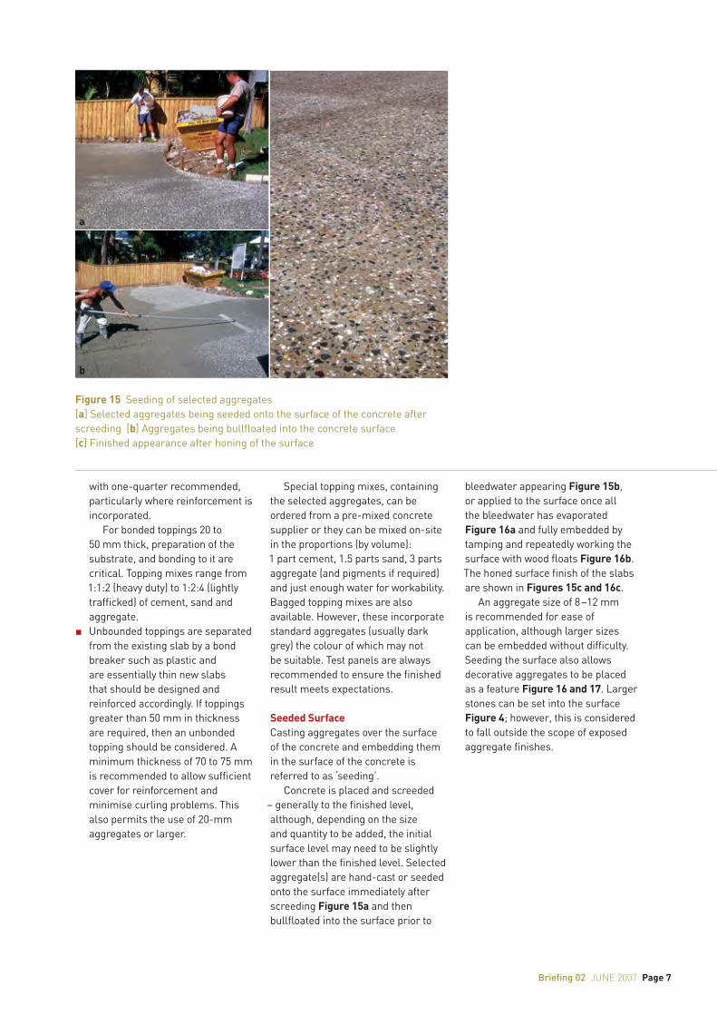
Seeded SurfaceCasting aggregates over the surface of the concrete and embedding them in the surface of the concrete is referred to as ‘seeding’.
Concrete is placed and screeded – generally to the finished level, although, depending on the size and quantity to be added, the initial surface level may need to be slightly lower than the finished level. Selected aggregate(s) are hand-cast or seeded onto the surface immediately after screeding Figure 15a and then bullfloated into the surface prior to
bleedwater appearing Figure 15b, or applied to the surface once all the bleedwater has evaporated Figure 16a and fully embedded by tamping and repeatedly working the surface with wood floats Figure 16b. The honed surface finish of the slabs are shown in Figures 15c and 16c.
An aggregate size of 8 –12 mm is recommended for ease of application, although larger sizes can be embedded without difficulty. Seeding the surface also allows decorative aggregates to be placed as a feature Figure 16 and 17. Larger stones can be set into the surface Figure 4; however, this is considered to fall outside the scope of exposed aggregate finishes.
Figure 15 Seeding of selected aggregates[a] Selected aggregates being seeded onto the surface of the concrete after screeding [b] Aggregates being bullfloated into the concrete surface [c] Finished appearance after honing of the surface
a
b c

Page 8 Briefing 02 june 2007
Setting Aggregates into the SurfaceTo create intricate patterns, the aggregates are generally set into the surface of the concrete or topping Figures 18 and 19. The aggregate size must be appropriate to define the pattern, details and different colours. To allow sufficient time to place aggregates over large areas, they may be placed into a dry mortar bed which is then watered Figure 18a; alternatively, set retarders can be added to the concrete to allow more time to embed the stones (Figure 18b). Large areas can also be divided into smaller, more manageable sections. Similar to setting special features into the surface and then embedding these in concrete, the polished stones in Figure 19 were set in position and then gaps filled with a mortar mix.
Large areas can also be constructed using smaller precast sections. This method has the advantage of off-site fabrication which reduces installation time and inconvenience to the public Figures 20 and 21. With this method, pebbles are set into a sand bed and then the concrete is placed.
EXPOSING AGGREGATESThe common methods used to expose aggregates are water washing, abrasive blasting, honing and acid etching. Each should be undertaken only by experienced contractors. Test panels are recommended to assess techniques, surface finish, distribution of aggregates and, if applicable, consistency of colour.
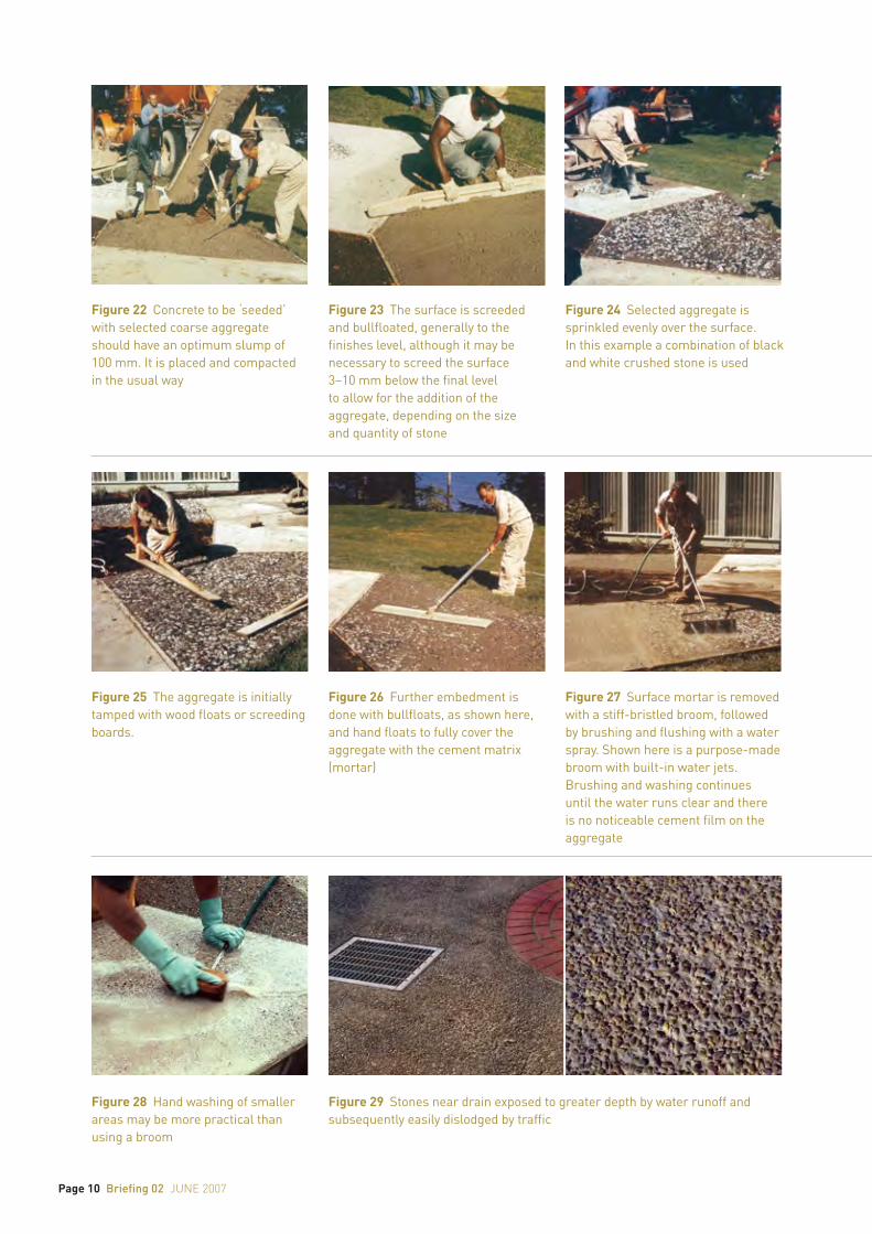
Water Wash-off TechniqueThe water wash-off technique removes the cement matrix at the surface of the slab by brushing and flushing the surface with water soon after the concrete has stiffened. Generally, this technique is used when the objective is to reveal large aggregates by up to a third of their size. The shape and surface texture of the aggregates are unaffected by the process, unlike abrasive blasting and honing (grinding) which affect the texture and, in the case of honing, the shape of the aggregates. The process is shown in Figures 22 to 27 for a surface that is seeded with a large aggregate.
Aggregate exposure begins when the surface can bear the weight of the paviour without making surface impressions deeper than 2 to 3 mm. A medium-bristle broom, together with a continuous water spray, is used to wash away the cement matrix. The surface should not be broomed repeatedly because this will weaken the mortar and dislodge aggregates. Often re-trowelling of the surface may be necessary to tightly pack the aggregate particles for a better finish, and the washing process repeated.
Smaller sections can be done by hand using a sponge Figure 28, while smaller aggregates such as those used in pebblecrete require a finer water spray to avoid washing the stones out of the concrete surface. Similarly, if washing large areas, water runoff should not be allowed to build to the point where stones are either washed out or exposed more than one third of their depth Figure 29.
Figure 16 Decorative aggregate used as feature in Bourke Street Mall, Melbourne (Artist: David Humphries, Public Art Squad)[a] Seeding aggregates onto surface [b] Floating aggregates into surface [c] Surface after honing
Figure 17 Surface seeded with large decorative white quartz aggregate(Mt Keira Summit Park, NSW)
a
b c

Briefing 02 june 2007 Page 9
Figure 18 Coloured gravels set into surface to form patterns[a] Aggregates set into cement mortar topping [b] Aggregates set into concrete path create spiral pattern
Figure 20 Pebble mosaic formed from smaller precast elements in Parterre Garden, Queens Park, Toowoomba (Artist: Naomi Hatt)[a] Completed work [b] Installing precast sections [c] Individual precast section
Figure 19 Polished stone (aggregate) embedded in cement mortar topping (Mural in forecourt Parliament House, Canberra)
Figure 21 ‘Koala’ pebble mosaic. Pittsworth Shire Council (Artist: Naomi Hatt)
a
b
a
b
c
Page 10 Briefing 02 june 2007
Figure 22 Concrete to be ‘seeded’ with selected coarse aggregate should have an optimum slump of 100 mm. It is placed and compacted in the usual way
Figure 25 The aggregate is initially tamped with wood floats or screeding boards.
Figure 23 The surface is screeded and bullfloated, generally to the finishes level, although it may be necessary to screed the surface 3–10 mm below the final level to allow for the addition of the aggregate, depending on the size and quantity of stone
Figure 26 Further embedment is done with bullfloats, as shown here, and hand floats to fully cover the aggregate with the cement matrix (mortar)
Figure 24 Selected aggregate is sprinkled evenly over the surface. In this example a combination of black and white crushed stone is used
Figure 27 Surface mortar is removed with a stiff-bristled broom, followed by brushing and flushing with a water spray. Shown here is a purpose-made broom with built-in water jets. Brushing and washing continues until the water runs clear and there is no noticeable cement film on the aggregate
Figure 28 Hand washing of smaller areas may be more practical than using a broom
Figure 29 Stones near drain exposed to greater depth by water runoff and subsequently easily dislodged by traffic
Briefing 02 june 2007 Page 11
The use of water-based surface set-retarders could also be considered. Those that are developed specially for this technique slow the setting time of the surface of the slab to a predetermined depth without affecting the set of the mass of the concrete. A consistent depth of exposure will be obtained with uniform application of the product. They are very useful when drying weather conditions would otherwise limit the time available for aggregate exposure.
If set retarders are applied at varying thicknesses, different depths of aggregate exposure and hence intensity of colour from the aggregate will result when the surface is water washed. This is the process behind photo-engraved concrete images.
After exposure of aggregates, the surface is cured for a minimum period depending on the location and application. A minimum of 7 days curing is recommended for increased concrete strength and improved bonding of the aggregates into the surface.
An acid-wash treatment (1 hydrochloric acid to between 10 and 20 parts water) is usually necessary to brighten up the stones by removing the fine cement film from the surface. The surface should first be thoroughly wetted to prevent acid soaking into the concrete and weakening the bond to the exposed aggregates. The surface should afterwards be rinsed with clean water to remove all residual acid. A surface sealer may be applied if desired. If a curing compound has been applied, acid washing should be delayed until the curing compound has degraded and worn off the surface.
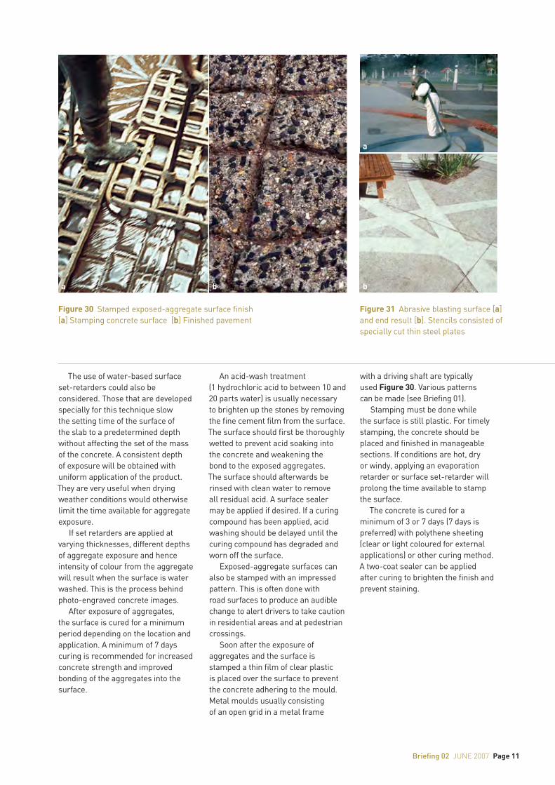
Exposed-aggregate surfaces can also be stamped with an impressed pattern. This is often done with road surfaces to produce an audible change to alert drivers to take caution in residential areas and at pedestrian crossings.
Soon after the exposure of aggregates and the surface is stamped a thin film of clear plastic is placed over the surface to prevent the concrete adhering to the mould. Metal moulds usually consisting of an open grid in a metal frame
with a driving shaft are typically used Figure 30. Various patterns can be made (see Briefing 01).
Stamping must be done while the surface is still plastic. For timely stamping, the concrete should be placed and finished in manageable sections. If conditions are hot, dry or windy, applying an evaporation retarder or surface set-retarder will prolong the time available to stamp the surface.
The concrete is cured for a minimum of 3 or 7 days (7 days is preferred) with polythene sheeting (clear or light coloured for external applications) or other curing method. A two-coat sealer can be applied after curing to brighten the finish and prevent staining.
Figure 30 Stamped exposed-aggregate surface finish[a] Stamping concrete surface [b] Finished pavement
Figure 31 Abrasive blasting surface [a] and end result [b]. Stencils consisted of specially cut thin steel plates
a b
a
b
Page 12 Briefing 02 june 2007
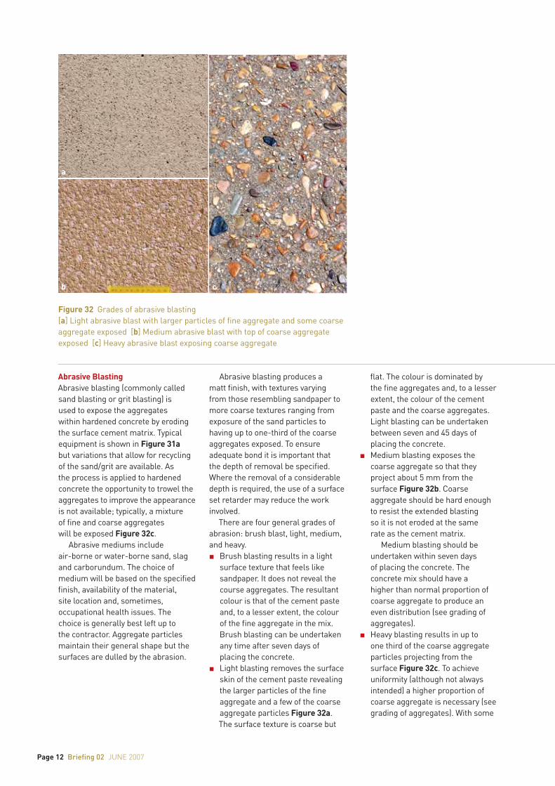
Abrasive BlastingAbrasive blasting (commonly called sand blasting or grit blasting) is used to expose the aggregates within hardened concrete by eroding the surface cement matrix. Typical equipment is shown in Figure 31a but variations that allow for recycling of the sand/grit are available. As the process is applied to hardened concrete the opportunity to trowel the aggregates to improve the appearance is not available; typically, a mixture of fine and coarse aggregates will be exposed Figure 32c.
Abrasive mediums include air-borne or water-borne sand, slag and carborundum. The choice of medium will be based on the specified finish, availability of the material, site location and, sometimes, occupational health issues. The choice is generally best left up to the contractor. Aggregate particles maintain their general shape but the surfaces are dulled by the abrasion.
Abrasive blasting produces a matt finish, with textures varying from those resembling sandpaper to more coarse textures ranging from exposure of the sand particles to having up to one-third of the coarse aggregates exposed. To ensure adequate bond it is important that the depth of removal be specified. Where the removal of a considerable depth is required, the use of a surface set retarder may reduce the work involved.
There are four general grades of abrasion: brush blast, light, medium, and heavy.n Brush blasting results in a light
surface texture that feels like sandpaper. It does not reveal the course aggregates. The resultant colour is that of the cement paste and, to a lesser extent, the colour of the fine aggregate in the mix. Brush blasting can be undertaken any time after seven days of placing the concrete.
n Light blasting removes the surface skin of the cement paste revealing the larger particles of the fine aggregate and a few of the coarse aggregate particles Figure 32a. The surface texture is coarse but
flat. The colour is dominated by the fine aggregates and, to a lesser extent, the colour of the cement paste and the coarse aggregates. Light blasting can be undertaken between seven and 45 days of placing the concrete.
n Medium blasting exposes the coarse aggregate so that they project about 5 mm from the surface Figure 32b. Coarse aggregate should be hard enough to resist the extended blasting so it is not eroded at the same rate as the cement matrix.
Medium blasting should be undertaken within seven days of placing the concrete. The concrete mix should have a higher than normal proportion of coarse aggregate to produce an even distribution (see grading of aggregates).
n Heavy blasting results in up to one third of the coarse aggregate particles projecting from the surface Figure 32c. To achieve uniformity (although not always intended) a higher proportion of coarse aggregate is necessary (see grading of aggregates). With some
Figure 32 Grades of abrasive blasting[a] Light abrasive blast with larger particles of fine aggregate and some coarse aggregate exposed [b] Medium abrasive blast with top of coarse aggregate exposed [c] Heavy abrasive blast exposing coarse aggregate
a
b c
Briefing 02 june 2007 Page 13
exceptions, there is little point in specifying a heavy blast if there are few aggregate particles to reveal. The colour is generally dominated by the coarse aggregates.
Heavy blasting should be undertaken within 24 hours of placing the concrete (prior to any significant strength gain) to reduce the work involved in removing a considerable depth of the cement matrix. A chemical set retarder is recommended for medium and heavy blasting. This will generally help achieve a more uniform and economical finish.In recent years, interesting
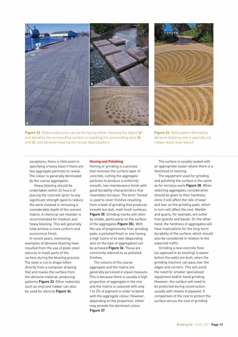
examples of abrasive blasting have resulted from the use of plate-steel stencils to mask parts of the surface during the blasting process. The steel is cut to shape (often directly from a computer drawing file) and masks the surface from the abrasive material, producing patterns Figure 33. Other materials such as vinyl and rubber can also be used for stencils Figure 34.
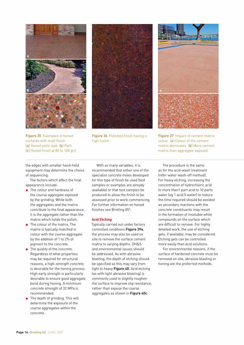
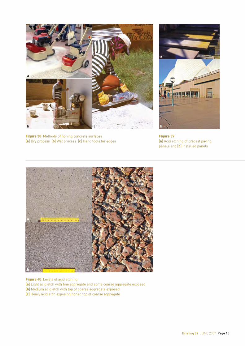
Honing and PolishingHoning or grinding is a process that removes the surface layer of concrete, cutting the aggregate particles to produce a uniformly smooth, low-maintenance finish with good durability characteristics that resembles terrazzo. The term ‘honed’ is used to cover finishes resulting from a level of grinding that produces smooth but dull, matt finish surfaces Figure 35. Grinding marks will often be visible, particularly on the surface of the aggregates Figure 35c. With the use of progressively finer grinding pads, a polished finish or one having a high lustre of its own (depending also on the type of aggregates) can be achieved Figure 36. These are commonly referred to as polished finishes.
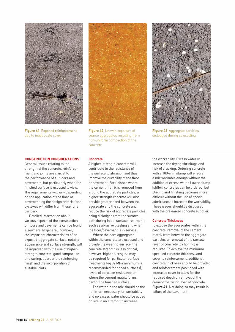
The colours of the coarse aggregate and the matrix are generally perceived in equal measure. This is because there is usually a high proportion of aggregate in the mix and the matrix is coloured with only 1 to 2% of pigment in order to blend with the aggregate colour. However, depending on the proportion, either may provide the dominant colour Figure 37.
The surface is usually sealed with an appropriate sealer where there is a likelihood of staining.
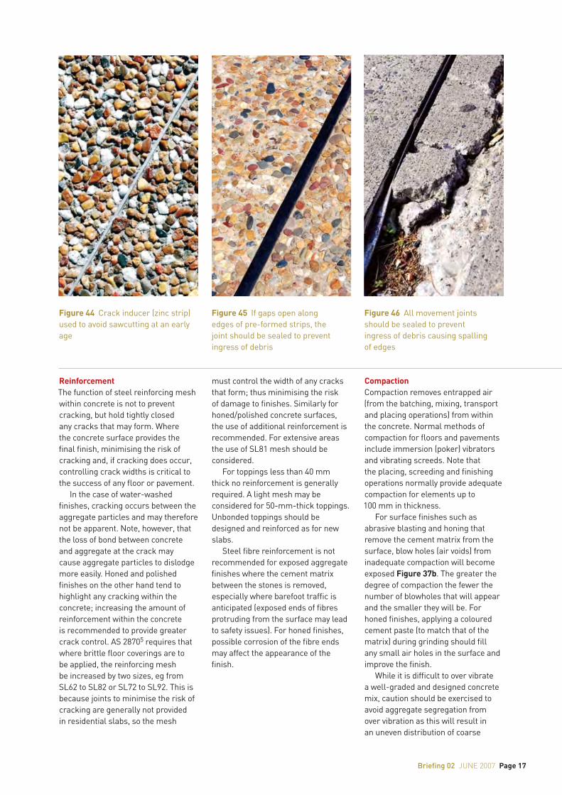
The equipment used for grinding and polishing the surface is the same as for terrazzo work Figure 38. When selecting aggregates consideration should be given to their hardness since it will affect the rate of wear and tear on the grinding pads, which in turn will affect the cost. Marble and quartz, for example, are softer than granite and basalt. On the other hand, the hardness of aggregates will have implications for the long-term durability of the surface, which should also be considered in relation to the expected traffic.
Grinding a new concrete floor (as opposed to an existing) is easier before the walls are built, when the grinding machine can pass over the edges and corners. This will avoid the need for smaller specialised equipment and/or hand grinding. However, the surface will need to be protected during construction: usually with sheets of plywood. A comparison of the cost to protect the surface versus the cost of grinding
Figure 33 Patterns/pictures can be formed by either masking the object [a] and abrading the surrounding surface or masking the surrounding area [b] and [c] and abrasive blasting the actual object/pattern
Figure 34 Shell pattern formed by abrasive blasting over a specially cut rubber-back-vinyl stencil
a c
b
Page 14 Briefing 02 june 2007
the edges with smaller hand-held equipment may determine the choice of sequencing.
The factors which affect the final appearance include:n The colour and hardness of
the course aggregate exposed by the grinding. While both the aggregates and the matrix contribute to the final appearance, it is the aggregate rather than the matrix which holds the polish.
n The colour of the matrix. The matrix is typically matched in colour with the course aggregate by the addition of 1 to 2% of pigment to the concrete.
n The quality of the concrete. Regardless of what properties may be required for structural reasons, a high-strength concrete is desirable for the honing process. High early strength is particularly desirable to ensure good aggregate bond during honing. A minimum concrete strength of 32 MPa is recommended.
n The depth of grinding. This will determine the exposure of the coarse aggregates within the concrete.
With so many variables, it is recommended that either one of the specialist concrete mixes developed for this type of finish be used (test samples or examples are already available) or that test samples be produced to allow the finish to be assessed prior to work commencing. For further information on honed finishes see Briefing 054.
Acid EtchingTypically carried out under factory controlled conditions Figure 39a, the process may also be used on site to remove the surface cement matrix to varying depths. OH&S and environmental issues should be addressed. As with abrasive blasting, the depth of etching should be specified as this may vary from light to heavy Figure 40. Acid etching (as with light abrasive blasting) is commonly used to slightly roughen the surface to improve slip resistance, rather than expose the coarse aggregates as shown in Figure 40c.
The procedure is the same as for the acid-wash treatment (refer water wash-off method). For heavy etching, increasing the concentration of hydrochloric acid to more than1 part acid to 10 parts water (eg 1 acid:5 water) to reduce the time required should be avoided as secondary reactions with the concrete constituents may result in the formation of insoluble white compounds on the surface which are difficult to remove. For highly detailed work, the use of etching gels, if available, may be considered. Etching gels can be controlled more easily than acid solutions.
For environmental reasons, if the surface of hardened concrete must be removed on site, abrasive blasting or honing are the preferred methods.
Figure 35 Examples of honed surfaces with matt finish[a] Honed patio slab [b] Path [c] Honed finish at 80 to 100 grit
Figure 36 Polished finish having a high lustre
Figure 37 Impact of cement matrix colour [a] Colour of the cement matrix dominates [b] More cement matrix than aggregate exposed
a
b
c
a
b
Briefing 02 june 2007 Page 15
Figure 39 [a] Acid etching of precast paving panels and [b] Installed panels
Figure 38 Methods of honing concrete surfaces[a] Dry process [b] Wet process [c] Hand tools for edges
Figure 40 Levels of acid etching[a] Light acid etch with fine aggregate and some coarse aggregate exposed [b] Medium acid etch with top of coarse aggregate exposed [c] Heavy acid etch exposing honed top of coarse aggregate
a
b c
a
b
a
b c
Page 16 Briefing 02 june 2007
CONSTRUCTION CONSIDERATIONSGeneral issues relating to the strength of the concrete, reinforce-ment and joints are crucial to the performance of all floors and pavements, but particularly when the finished surface is exposed to view. The requirements will vary depending on the application of the floor or pavement, eg the design criteria for a cycleway will differ from those for a car park.
Detailed information about various aspects of the construction of floors and pavements can be found elsewhere. In general, however, the important characteristics of an exposed-aggregate surface, notably appearance and surface strength, will be improved with the use of higher-strength concrete, good compaction and curing, appropriate reinforcing mesh and the incorporation of suitable joints.
ConcreteA higher-strength concrete will contribute to the resistance of the surface to abrasion and thus improve the durability of the floor or pavement. For finishes where the cement matrix is removed from around the aggregate particles, a higher strength concrete will also provide greater bond between the aggregate and the concrete and reduce the risk of aggregate particles being dislodged from the surface, both during initial surface treatments such as abrasive blasting and when the floor/pavement is in service.
Where the hard aggregates within the concrete are exposed and provide the wearing surface, the concrete strength is less critical, however, higher strengths may be required for particular surface treatments (eg 32 MPa minimum is recommended for honed surfaces), levels of abrasion resistance or where the cement matrix forms part of the finished surface.
The water in the mix should be the minimum necessary for workability and no excess water should be added on site in an attempt to increase
the workability. Excess water will increase the drying shrinkage and risk of cracking. Ordering concrete with a 100-mm slump will ensure a mix workable enough without the addition of excess water. Lower slump (stiffer) concretes can be ordered, but placing and finishing becomes more difficult without the use of special admixtures to increase the workability. These issues should be discussed with the pre-mixed concrete supplier.
Concrete ThicknessTo expose the aggregates within the concrete, removal of the cement matrix from between the aggregate particles or removal of the surface layer of concrete (by honing) is required. To achieve the minimum specified concrete thickness and cover to reinforcement, additional concrete thickness should be provided and reinforcement positioned with increased cover to allow for the required depth of removal of the cement matrix or layer of concrete Figure 41. Not doing so may result in failure of the pavement.
Figure 41 Exposed reinforcement due to inadequate cover
Figure 42 Uneven exposure of coarse aggregates resulting from non-uniform compaction of the concrete
Figure 43 Aggregate particles dislodged during sawcutting
Briefing 02 june 2007 Page 17
ReinforcementThe function of steel reinforcing mesh within concrete is not to prevent cracking, but hold tightly closed any cracks that may form. Where the concrete surface provides the final finish, minimising the risk of cracking and, if cracking does occur, controlling crack widths is critical to the success of any floor or pavement.
In the case of water-washed finishes, cracking occurs between the aggregate particles and may therefore not be apparent. Note, however, that the loss of bond between concrete and aggregate at the crack may cause aggregate particles to dislodge more easily. Honed and polished finishes on the other hand tend to highlight any cracking within the concrete; increasing the amount of reinforcement within the concrete is recommended to provide greater crack control. AS 28705 requires that where brittle floor coverings are to be applied, the reinforcing mesh be increased by two sizes, eg from SL62 to SL82 or SL72 to SL92. This is because joints to minimise the risk of cracking are generally not provided in residential slabs, so the mesh
must control the width of any cracks that form; thus minimising the risk of damage to finishes. Similarly for honed/polished concrete surfaces, the use of additional reinforcement is recommended. For extensive areas the use of SL81 mesh should be considered.
For toppings less than 40 mm thick no reinforcement is generally required. A light mesh may be considered for 50-mm-thick toppings. Unbonded toppings should be designed and reinforced as for new slabs.
Steel fibre reinforcement is not recommended for exposed aggregate finishes where the cement matrix between the stones is removed, especially where barefoot traffic is anticipated (exposed ends of fibres protruding from the surface may lead to safety issues). For honed finishes, possible corrosion of the fibre ends may affect the appearance of the finish.
CompactionCompaction removes entrapped air (from the batching, mixing, transport and placing operations) from within the concrete. Normal methods of compaction for floors and pavements include immersion (poker) vibrators and vibrating screeds. Note that the placing, screeding and finishing operations normally provide adequate compaction for elements up to 100 mm in thickness.
For surface finishes such as abrasive blasting and honing that remove the cement matrix from the surface, blow holes (air voids) from inadequate compaction will become exposed Figure 37b. The greater the degree of compaction the fewer the number of blowholes that will appear and the smaller they will be. For honed finishes, applying a coloured cement paste (to match that of the matrix) during grinding should fill any small air holes in the surface and improve the finish.
While it is difficult to over vibrate a well-graded and designed concrete mix, caution should be exercised to avoid aggregate segregation from over vibration as this will result in an uneven distribution of coarse
Figure 44 Crack inducer (zinc strip) used to avoid sawcutting at an early age
Figure 45 If gaps open along edges of pre-formed strips, the joint should be sealed to prevent ingress of debris
Figure 46 All movement joints should be sealed to prevent ingress of debris causing spalling of edges
Page 18 Briefing 02 june 2007
aggregates. For honed finished, uneven vibration may result in aggregate particles settling more at the point where the vibrator was inserted Figure 42. Vibrators dragged through the concrete can also cause lines or streaks in the exposed surface.
CrackingMinimising the risk long-term drying shrinkage cracking and controlling crack widths if they do occur, will improve the appearance of any concrete finish. Drying shrinkage occurs as a result of water in the concrete drying out over time. All concrete will shrink, but measures can be taken to limit or control it.
Basic quality issues such as not adding excess water to the mix, adequate compaction and curing are a good place to start and among the most effective ways to reduce the risk of cracking. Keeping water to a minimum reduces the long-term drying shrinkage; compaction removes entrapped air and improves density and strength; and curing not only improves strength, but also delays shrinkage until the concrete has gained strength.
Increasing the amount of reinforcement (as discussed above) will also be beneficial in controlling the width of any cracks that do occur.
If possible, providing joints at centres appropriate to the slab thickness should be the first option employed for reducing the risk of cracking.
Should cracking occur, a generally acceptable crack width where visual appearance is important would be 0.3 mm. As mentioned above, the impact of such a crack depends on the surface finish with rougher water-washed finishes tending to conceal cracks and smooth polished finishes tending to highlight them.
JointsApart from house slabs, joints should be provided in all concrete pavements at spacings no more than 30 times the slab thickness. Both joints that allow movement (expansion and isolation) and those that are specifically intended to control shrinkage cracking (control or contraction) may be used to divide large areas into smaller ones to reduce the risk of uncontrolled random cracking, and to induce cracking at locations
(joints) where they are acceptable. For information on the different joint types, details and spacings refer Residential Concrete Driveways and Paths 6.
Some points to consider about joints include:n Sawcut control joints should be
installed (cut) within 12 to 18 hours after completion of the slab (depending on the temperature). With water wash-off finishes the aggregate particles are not bonded into the concrete for their full depth and at such an early age may tend to dislodge more during sawing Figure 43. The use of other types of control joints such as crack inducers (see below) and pre-formed metal joints that avoid sawcutting at an early age (while the concrete is still quite weak) could be considered Figure 44.
n Expansion joints with pre-formed strips along the top Figure 45 may still need to be sealed to prevent ingress of debris, locking up of the joint and damage to slab edges Figure 46.
Figure 47 Sealed joint to prevent ingress of sand and other non-compressible material (debris)
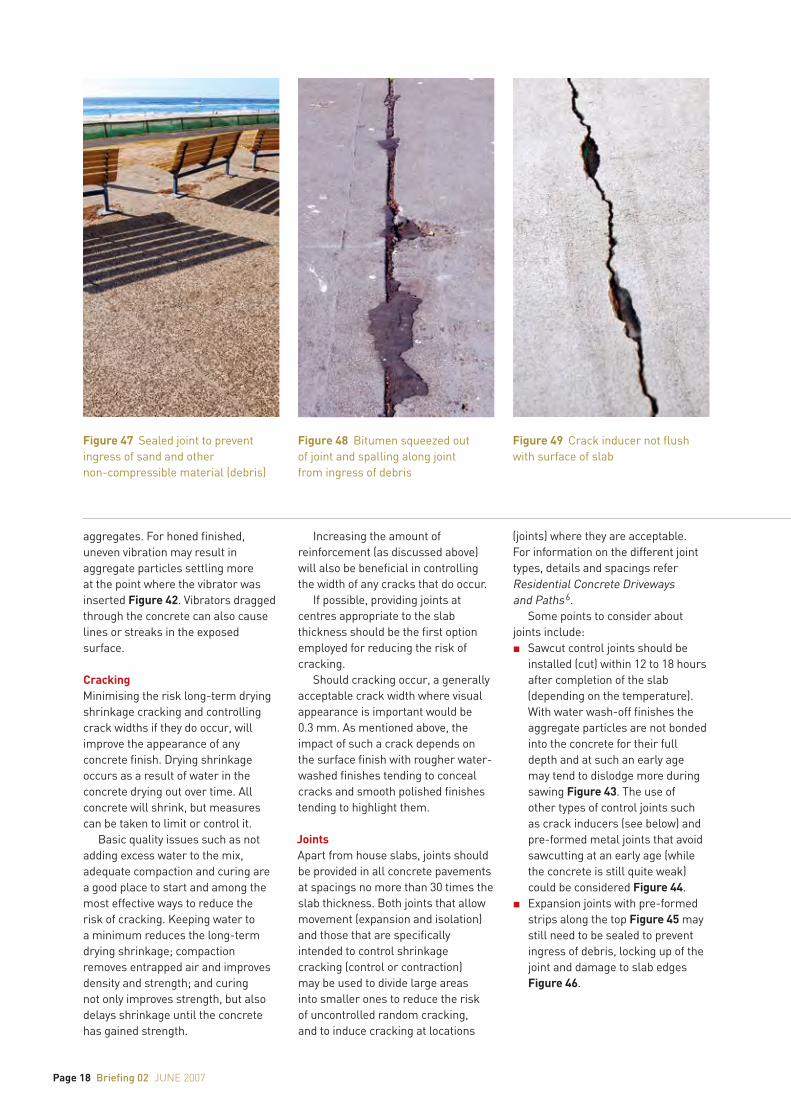
Figure 48 Bitumen squeezed out of joint and spalling along joint from ingress of debris
Figure 49 Crack inducer not flush with surface of slab
Briefing 02 june 2007 Page 19
n Movement joints should be sealed across the top and sides using sealants such as silicones and polyurethanes Figure 47. The colour of sealant can be selected to match that of the aggregate.
n Bitumen-impregnated fibreboard fillers in joints may not have sufficient compression and can detract from the appearance if squeezed out of the joint Figure 48.
n If crack inducers are used, they should be flush with the surface to avoid an irregular crack that allows sections to break off Figure 49.
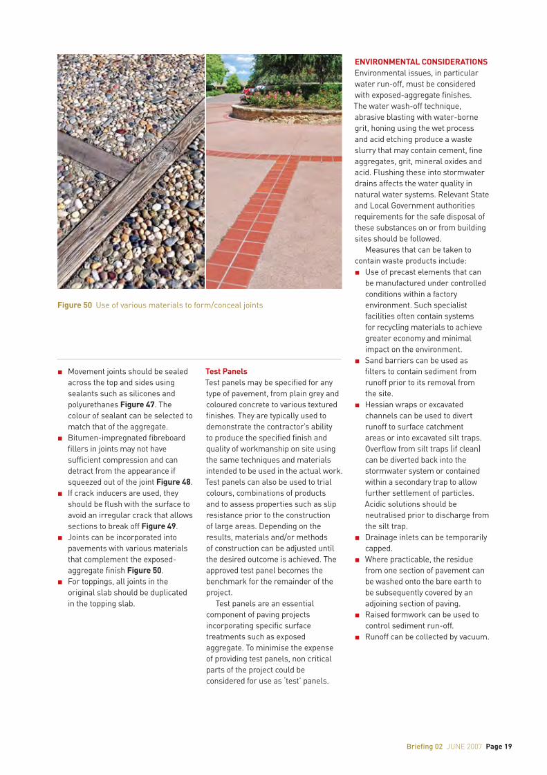
n Joints can be incorporated into pavements with various materials that complement the exposed-aggregate finish Figure 50.
n For toppings, all joints in the original slab should be duplicated in the topping slab.
Test PanelsTest panels may be specified for any type of pavement, from plain grey and coloured concrete to various textured finishes. They are typically used to demonstrate the contractor’s ability to produce the specified finish and quality of workmanship on site using the same techniques and materials intended to be used in the actual work. Test panels can also be used to trial colours, combinations of products and to assess properties such as slip resistance prior to the construction of large areas. Depending on the results, materials and/or methods of construction can be adjusted until the desired outcome is achieved. The approved test panel becomes the benchmark for the remainder of the project.
Test panels are an essential component of paving projects incorporating specific surface treatments such as exposed aggregate. To minimise the expense of providing test panels, non critical parts of the project could be considered for use as ‘test’ panels.
ENVIRONMENTAL CONSIDERATIONSEnvironmental issues, in particular water run-off, must be considered with exposed-aggregate finishes. The water wash-off technique, abrasive blasting with water-borne grit, honing using the wet process and acid etching produce a waste slurry that may contain cement, fine aggregates, grit, mineral oxides and acid. Flushing these into stormwater drains affects the water quality in natural water systems. Relevant State and Local Government authorities requirements for the safe disposal of these substances on or from building sites should be followed.
Measures that can be taken to contain waste products include:n Use of precast elements that can
be manufactured under controlled conditions within a factory environment. Such specialist facilities often contain systems for recycling materials to achieve greater economy and minimal impact on the environment.
n Sand barriers can be used as filters to contain sediment from runoff prior to its removal from the site.
n Hessian wraps or excavated channels can be used to divert runoff to surface catchment areas or into excavated silt traps. Overflow from silt traps (if clean) can be diverted back into the stormwater system or contained within a secondary trap to allow further settlement of particles. Acidic solutions should be neutralised prior to discharge from the silt trap.
n Drainage inlets can be temporarily capped.
n Where practicable, the residue from one section of pavement can be washed onto the bare earth to be subsequently covered by an adjoining section of paving.
n Raised formwork can be used to control sediment run-off.
n Runoff can be collected by vacuum.
Figure 50 Use of various materials to form/conceal joints
REFERENCES1 AS 2758.1 Aggregates and rock for Engineering purposes –
Concrete aggregates Standards Australia.2 Nasvik, Joe, ‘Decorative Concrete Using Glass Aggregate’
Concrete Construction, July 2006, pp 53–623 Colouring, Stencilling and Stamping Concrete Flatwork
Briefing 01, Cement Concrete & Aggregates Australia, 2007.4 Polished Concrete Floors Briefing 05,
Cement Concrete & Aggregates Australia, 2006.5 AS 2870 Residential slabs and footings – Construction
Standards Australia.6 Residential Concrete Driveways and Paths
Cement Concrete & Aggregates Australia, 2006.
Briefing 02 June 2007 supersedes Briefing 02 July 2000
OTHER BRIEFINGS available online from www.concrete.net.au are:
Briefing 01 Colouring, stencilling and stamping concrete flatwork
Briefing 03 Colour and texture in concrete walling
Briefing 04 Concrete panel homes
Briefing 05 Polished concrete floors
Briefing 06 Form liners achieving surface relief and texture
Briefing 07 Concrete floor heating
Briefing 08 Concrete panel buildings
Briefing 09 Passive solar design
02june 2007
CCAA OFFICES
SYDNEY OFFICE:Level 6, 504 Pacific Highway St Leonards NSW Australia 2065 POSTAL ADDRESS: Locked Bag 2010 St Leonards NSW 1590TELEPHONE: (61 2) 9437 9711 FACSIMILE: (61 2) 9437 9470
BRISBANE OFFICE: Level 14, IBM Building 348 Edward Street Brisbane QLD 4000TELEPHONE: (61 7) 3831 3288FACSIMILE: (61 7) 3839 6005
MELBOURNE OFFICE:2nd Floor, 1 Hobson Street South Yarra VIC 3141 TELEPHONE: (61 3) 9825 0200FACSIMILE: (61 3) 9825 0222
PERTH OFFICE:45 Ventnor Avenue West Perth WA 6005 TELEPHONE: (61 8) 9389 4452FACSIMILE: (61 8) 9389 4451
ADELAIDE OFFICE:Greenhill Executive Suites 213 Greenhill RoadEastwood SA 5063 POSTAL ADDRESS:PO Box 229 Fullarton SA 5063TELEPHONE: (61 8) 8274 3758FACSIMILE: (61 8) 8373 7210
EXTRACTIVE INDUSTRIES OFFICEPO Box 243Henley Beach SA 5022TELEPHONE: (61 8) 8353 8151FACSIMILE: (61 8) 8353 8151
TASMANIAN OFFICE: EXTRACTIVE INDUSTRIES OFFICEPO Box 246Sheffield TAS 7306TELEPHONE: (61 3) 6491 2529FACSIMILE: (61 3) 6491 2529
WEBSITE: www.concrete.net.au
EMAIL: [email protected]
LAYOUT: Helen Rix Design
Disclaimer: Cement Concrete & Aggregates Australia is a not for profit organisation sponsored by the cement concrete and aggregate industries in Australia to provide information on the many uses of cement and concrete. This publication is produced by CCAA for that purpose. Since the information provided is intended for general guidance only and in no way replaces the services of professional consultants on particular projects, no legal liability can be accepted by CCAA for its use.
CCAA respects your privacy. Your details have been collected to provide you with information on our activities, publications and services. From time to time your details may be made available to third party organisations who comply with the Privacy Act such as affiliated associations, sponsors of events and other reputable organisations whose services we think you may find of interest. If you do not wish to receive information from CCAA or wish to be taken off the database please write to the Privacy Officer, CCAA, Locked Bag 2010, St Leonards, NSW, 1590
ISBN 978-1-877023-23-1