explanation of terms - rs...
TRANSCRIPT
K-24 For more Information: U.S. www.sensors.omron.com Canada www.sensors.omron.ca
Proximity sensor
Explanation of terms
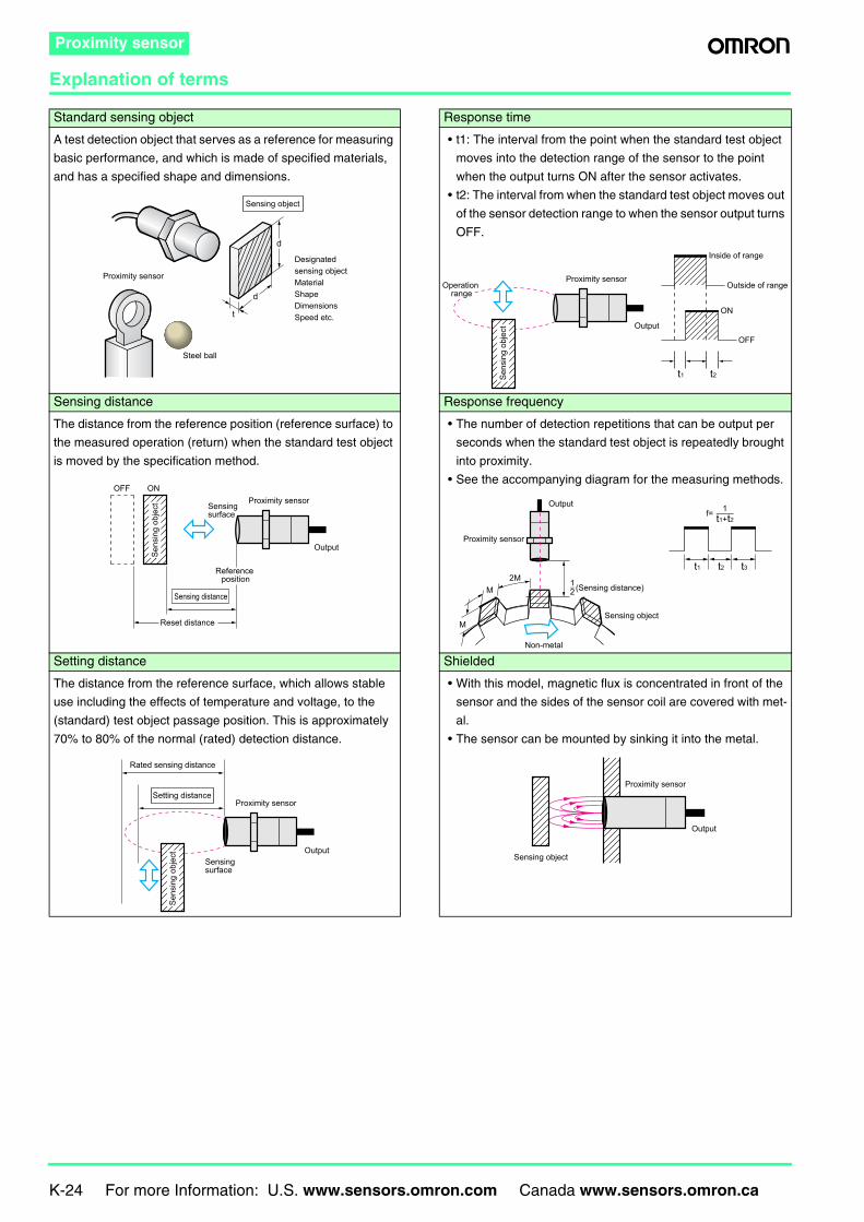
Standard sensing object Response time
A test detection object that serves as a reference for measuring
basic performance, and which is made of specified materials,
and has a specified shape and dimensions.
• t1: The interval from the point when the standard test object
moves into the detection range of the sensor to the point
when the output turns ON after the sensor activates.
• t2: The interval from when the standard test object moves out
of the sensor detection range to when the sensor output turns
OFF.
Sensing distance Response frequency
The distance from the reference position (reference surface) to
the measured operation (return) when the standard test object
is moved by the specification method.
• The number of detection repetitions that can be output per
seconds when the standard test object is repeatedly brought
into proximity.
• See the accompanying diagram for the measuring methods.
Setting distance Shielded
The distance from the reference surface, which allows stable
use including the effects of temperature and voltage, to the
(standard) test object passage position. This is approximately
70% to 80% of the normal (rated) detection distance.
• With this model, magnetic flux is concentrated in front of the
sensor and the sides of the sensor coil are covered with met-
al.
• The sensor can be mounted by sinking it into the metal.
d
Sensing object
Proximity sensor
Steel ball
Designated sensing objectMaterialShapeDimensionsSpeed etc.
d
t
Inside of range
Outside of range
ON
t1 t2
OFF
Proximity sensor
Output
Sens
ing
obje
ct
Operation range
Reset distance
Proximity sensor
Output
Sensing surface
Sensing distance
Sens
ing
obje
ct
OFF ON
Reference position
(Sensing distance)
Sensing object
1−2
f= 1−t1+t2
Proximity sensor
Output
Non-metal
M
M
2Mt1 t3t2
Setting distance
Sensing surface
Proximity sensor
Rated sensing distance
Output
Sens
ing
obje
ct
Output
Proximity sensor
Sensing object
For more Information: U.S. www.sensors.omron.com Canada www.sensors.omron.ca K-25
Proximity sensor
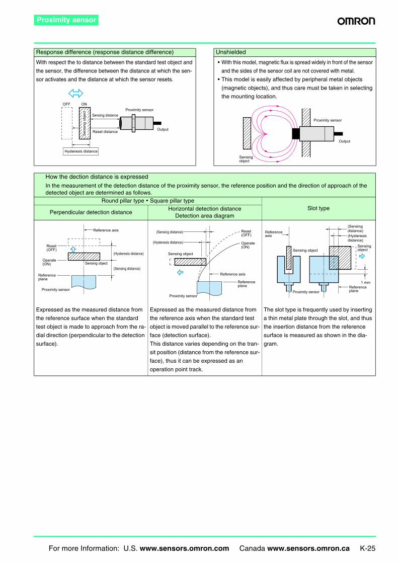
Response difference (response distance difference) Unshielded
With respect the to distance between the standard test object and
the sensor, the difference between the distance at which the sen-
sor activates and the distance at which the sensor resets.
• With this model, magnetic flux is spread widely in front of the sensor
and the sides of the sensor coil are not covered with metal.
• This model is easily affected by peripheral metal objects
(magnetic objects), and thus care must be taken in selecting
the mounting location.
How the dection distance is expressed
In the measurement of the detection distance of the proximity sensor, the reference position and the direction of approach of the detected object are determined as follows.
Round pillar type • Square pillar typeSlot type
Perpendicular detection distanceHorizontal detection distance
Detection area diagram
Expressed as the measured distance from
the reference surface when the standard
test object is made to approach from the ra-
dial direction (perpendicular to the detection
surface).
Expressed as the measured distance from
the reference axis when the standard test
object is moved parallel to the reference sur-
face (detection surface).
This distance varies depending on the tran-
sit position (distance from the reference sur-
face), thus it can be expressed as an
operation point track.
The slot type is frequently used by inserting
a thin metal plate through the slot, and thus
the insertion distance from the reference
surface is measured as shown in the dia-
gram.
Reset distance
Sensing distanceProximity sensor
Output
Hysteresis distance
OFF ON
Sens
ing
obje
ct
Output
Proximity sensor
Sensing object
Reference axis
Proximity sensor
(Hysteresis distance)
(Sensing distance)
Reset (OFF)
Operate (ON)
Reference plane
Sensing object
Reference axis
Proximity sensor
(Hysteresis distance)
(Sensing distance) Reset (OFF)
Operate (ON)
Reference plane
Sensing objectSensing object
Sensing object
Proximity sensorReference plane
Reference axis (Hysteresis
distance)
(Sensing distance)
1 mm
K-26 For more Information: U.S. www.sensors.omron.com Canada www.sensors.omron.ca
Proximity sensor
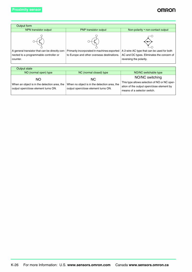
Output formNPN transistor output PNP transistor output Non-polarity • non-contact output
A general transistor that can be directly con-
nected to a programmable controller or
counter.
Primarily incorporated in machines exported
to Europe and other overseas destinations.
A 2-wire AC type that can be used for both
AC and DC types. Eliminates the concern of
reversing the polarity.
Output stateNO (normal open) type NC (normal closed) type NO/NC switchable type
NOWhen an object is in the detection area, the
output open/close element turns ON.
NCWhen no object is in the detection area, the
output open/close element turns ON.
NO/NC switchingThis type allows selection of NO or NC oper-
ation of the output open/close element by
means of a selector switch.
For more Information: U.S. www.sensors.omron.com Canada www.sensors.omron.ca K-27
Proximity sensor
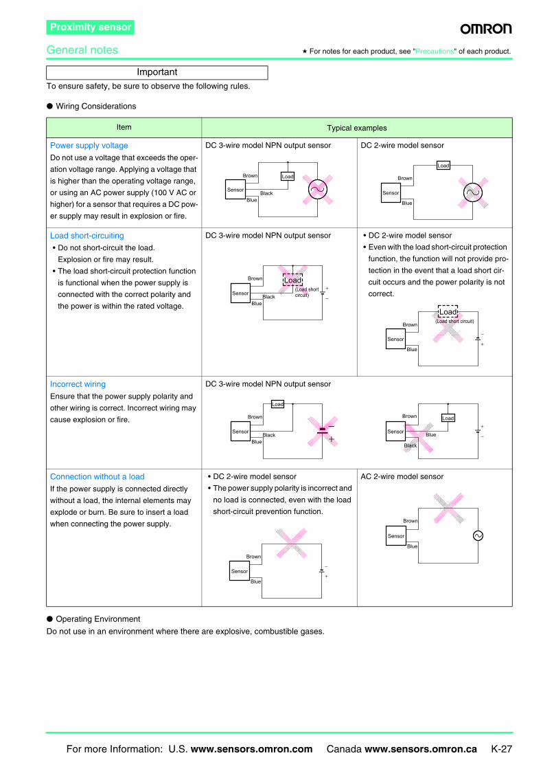
General notes * For notes for each product, see "Precautions" of each product.
To ensure safety, be sure to observe the following rules.
Wiring Considerations
Operating Environment
Do not use in an environment where there are explosive, combustible gases.
Important
Item Typical examples
Power supply voltage
Do not use a voltage that exceeds the oper-
ation voltage range. Applying a voltage that
is higher than the operating voltage range,
or using an AC power supply (100 V AC or
higher) for a sensor that requires a DC pow-
er supply may result in explosion or fire.
DC 3-wire model NPN output sensor DC 2-wire model sensor
Load short-circuiting
• Do not short-circuit the load.
Explosion or fire may result.
• The load short-circuit protection function
is functional when the power supply is
connected with the correct polarity and
the power is within the rated voltage.
DC 3-wire model NPN output sensor • DC 2-wire model sensor
• Even with the load short-circuit protection
function, the function will not provide pro-
tection in the event that a load short cir-
cuit occurs and the power polarity is not
correct.
Incorrect wiring
Ensure that the power supply polarity and
other wiring is correct. Incorrect wiring may
cause explosion or fire.
DC 3-wire model NPN output sensor
Connection without a load
If the power supply is connected directly
without a load, the internal elements may
explode or burn. Be sure to insert a load
when connecting the power supply.
• DC 2-wire model sensor
• The power supply polarity is incorrect and
no load is connected, even with the load
short-circuit prevention function.
AC 2-wire model sensor
Load
Sensor
Brown
BlueBlack
Load
Sensor
Brown
Blue
−
+Load
Sensor
Brown
BlueBlack
(Load short circuit)
+
−Sensor
Brown
Blue
Load(Load short circuit)
+−
Sensor−
+LoadBrown
Black
Blue
Load
Sensor
Brown
BlueBlack
+
−Sensor
Brown
Blue
Sensor
Brown
Blue
K-28 For more Information: U.S. www.sensors.omron.com Canada www.sensors.omron.ca
Proximity sensor
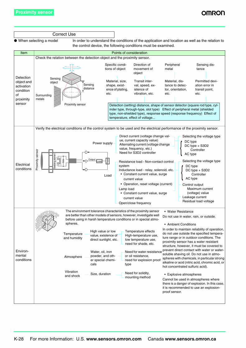
When selecting a model In order to understand the conditions of the application and location as well as the relation to the control device, the following conditions must be examined.
Correct Use
Item Points of consideration
Detection object and activation condition of proximity sensor
Check the relation between the detection object and the proximity sensor.
Electrical conditions
Verify the electrical conditions of the control system to be used and the electrical performance of the proximity sensor.
Environ-mental conditions
Transit inter-val, speed, ex-istence of vibration, etc.
Material, dis-tance to detec-tor, orientation, etc.
Permitted devi-ation error in transit point, etc.
Material, size, shape, exist-ence of plating, etc.
Specific condi-tions of object
Direction of movement of object
Peripheral metal
Sensing dis-tance
Detection (setting) distance, shape of sensor detector (square rod type, cyl-inder type, through-type, slot type) Effect of peripheral metal (shielded type, non-shielded type), response speed (response frequency) Effect of temperature, effect of voltage...
Sensing object
Proximity sensor
Sensing distance
Surrounding metals
Load Powe
r
Switc
hing e
lemen
t
Prox
imity
sen
sor
Output
Load
Resistance load - Non-contact control systemInductance load - relay, solenoid, etc.• Constant current value, surge
current value
• Operation, reset voltage (current)
Lamp load• Constant current value, surge
current value
Open/close frequency
Control outputMaximum current (voltage) value
Leakage currentResidual load voltage
Selecting the voltage typeDirect current (voltage change val-ue, current capacity value)Alternating current (voltage change value, frequency, etc.)Need for S3D2 controller
Selecting the voltage type
Power supply DC typeDC type + S3D2
ControllerAC type
DC typeDC type + S3D2
ControllerAC type
Temperature effects High-temperature use, low temperature use, need for shade, etc.
Need for water resistance or oil resistance, need for explosion proof type
Need for solidity, mounting method
The environment tolerance characteristics of the proximity sensor are better than other models of sensors, however, investigate well before using in harsh temperature conditions or in special atmo-spheres.
Temperature and humidity
Atmosphere
Vibration and shock
High value or low value, existence of direct sunlight, etc.
• Water Resistance
Do not use in water, rain, or outside.
• Ambient Conditions
In order to maintain reliability of operation, do not use outside the specified tempera-ture range or in outdoor conditions. The proximity sensor has a water resistant structure, however, it must be covered to prevent direct contact with water or water-soluble shaving oil. Do not use in atmo-spheres with chemicals, in particular strong alkaline or acid (nitric acid, chromic acid, or hot concentrated sulfuric acid).
• Explosive atmospheres
Cannot be used in atmospheres where there is a danger of explosion. In this case, it is recommended to use an explosion-proof sensor.
Water, oil, iron powder, and oth-er special chemi-cals
Size, duration
For more Information: U.S. www.sensors.omron.com Canada www.sensors.omron.ca K-29
Proximity sensor
Mounting conditions
Effect of external electromag-netic field
• The effect within a direct current magnetic field is 20 mT. Do not use at a level higher than 20 mT.
• Sudden changes in the direct current magnetic field may cause incorrect operation. Do not use for applications that involve turn-
ing the direct current electromagnet on and off.
• Do not place a transceiver near the proximity sensor or its wiring, as this may cause incorrect operation.
Other Accessories
Economical - Price / Delivery date Life - Power on time / Frequency of use
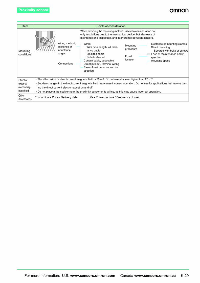
Item Points of consideration
When deciding the mounting method, take into consideration not only restrictions due to the mechanical device, but also ease of maintence and inspection, and interference between sensors.
Wiring method, existence of inductance surges
Connections
Mounting procedure
WiresWire type, length, oil resis-tance cableShielded cableRobot cable, etc.
Conduit cable, duct cableDirect pull-out, terminal wiringEase of maintenance and in-spection
Existence of mounting clampsDirect mounting
Secured with bolts or screwsEase of maintenance and in-spectionMounting space
Fixed location
K-30 For more Information: U.S. www.sensors.omron.com Canada www.sensors.omron.ca
Proximity sensor
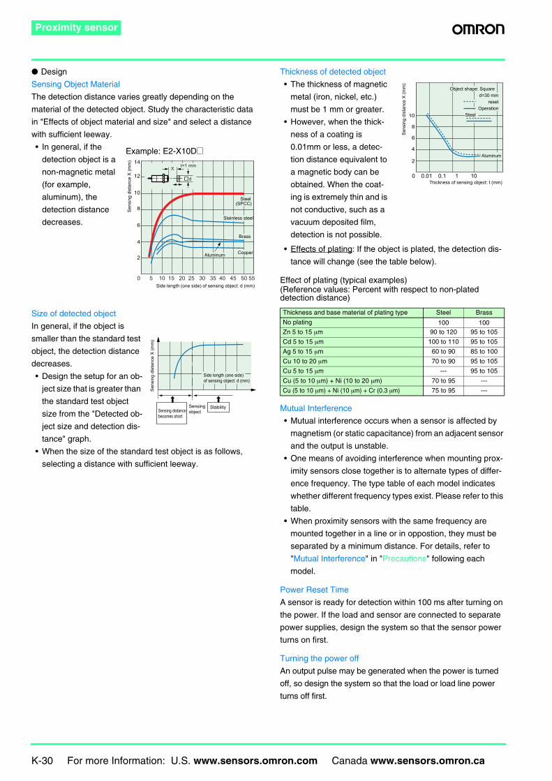
Design
Sensing Object Material
The detection distance varies greatly depending on the
material of the detected object. Study the characteristic data
in "Effects of object material and size" and select a distance
with sufficient leeway.
• In general, if the
detection object is a
non-magnetic metal
(for example,
aluminum), the
detection distance
decreases.
Size of detected object
In general, if the object is
smaller than the standard test
object, the detection distance
decreases.
• Design the setup for an ob-
ject size that is greater than
the standard test object
size from the "Detected ob-
ject size and detection dis-
tance" graph.
• When the size of the standard test object is as follows,
selecting a distance with sufficient leeway.
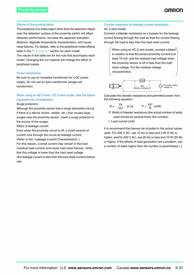
Thickness of detected object
• The thickness of magnetic
metal (iron, nickel, etc.)
must be 1 mm or greater.
• However, when the thick-
ness of a coating is
0.01mm or less, a detec-
tion distance equivalent to
a magnetic body can be
obtained. When the coat-
ing is extremely thin and is
not conductive, such as a
vacuum deposited film,
detection is not possible.
• Effects of plating: If the object is plated, the detection dis-
tance will change (see the table below).
Effect of plating (typical examples)(Reference values: Percent with respect to non-plated detection distance)
Mutual Interference
• Mutual interference occurs when a sensor is affected by
magnetism (or static capacitance) from an adjacent sensor
and the output is unstable.
• One means of avoiding interference when mounting prox-
imity sensors close together is to alternate types of differ-
ence frequency. The type table of each model indicates
whether different frequency types exist. Please refer to this
table.
• When proximity sensors with the same frequency are
mounted together in a line or in oppostion, they must be
separated by a minimum distance. For details, refer to
"Mutual Interference" in "Precautions" following each
model.
Power Reset Time
A sensor is ready for detection within 100 ms after turning on
the power. If the load and sensor are connected to separate
power supplies, design the system so that the sensor power
turns on first.
Turning the power off
An output pulse may be generated when the power is turned
off, so design the system so that the load or load line power
turns off first.
Aluminum Copper
Brass
Stainless steel
Steel(SPCC)
0 5 10 15 20 25 30 35 40 45 50 55Side length (one side) of sensing object: d (mm)
14
12
10
8
6
4
2
X
d
t=1 mm
Sens
ing
dist
ance
X (m
m)
Example: E2-X10D@
StabilitySensing distance becomes short
Sensing object
Sens
ing
dist
ance
X (m
m)
Side length (one side) of sensing object: d (mm)
Thickness and base material of plating type Steel Brass
No plating 100 100Zn 5 to 15 µm 90 to 120 95 to 105
Cd 5 to 15 µm 100 to 110 95 to 105
Ag 5 to 15 µm 60 to 90 85 to 100
Cu 10 to 20 µm 70 to 90 95 to 105
Cu 5 to 15 µm --- 95 to 105
Cu (5 to 10 µm) + Ni (10 to 20 µm) 70 to 95 ---
Cu (5 to 10 µm) + Ni (10 µm) + Cr (0.3 µm) 75 to 95 ---
Aluminum
Steel
0 0.01 0.1 1 10Thickness of sensing object: t (mm)
10
8
6
4
2
Sens
ing
dist
ance
X (m
m)
Object shape: Square d=30 mm
resetOperation
For more Information: U.S. www.sensors.omron.com Canada www.sensors.omron.ca K-31
Proximity sensor
Effects of Surrounding Metal
The existence of a metal object other than the detection object
near the detection surface of the proximity switch will affect
detection performance, increase the apparent activation
distance, degrade temperature characteristics, and cause
reset failures. For details, refer to the peripheral metal effects
table in the "Precautions" section for each model.
The values in the table are for the nuts that accompany each
model. Changing the nut material will change the effect of
peripheral metals.
Power transformer
Be sure to use an insulated transformer for a DC power
supply. Do not use an auto transformer (single-coil
transformer).
When using an AC 2-wire / DC 2-wire model, take the follow-
ing points into consideration.
Surge protection
Although the proximity sensor has a surge absorption circuit,
if there is a device (motor, welder, etc.) that causes large
surges near the proximity sensor, insert a surge protector in
the source of the surges.
Effect of leakage current
Even when the proximity circuit is off, a small amount of
current runs through the circuit as leakage current.
(Refer to the "Leakage Current Characteristics".)
For this reason, a small current may remain in the load
(residual load current) and cause load reset failures. Verify
that this voltage is lower than the load reset voltage
(the leakage current is less than the load reset current) before
use.
Counter measures for leakage current (examples)
AC 2-wire model
Connect a bleeder resistance as a bypass for the leakage
current flowing through the load so that the current flowing
through the load is less than the load reset current.
Calculate the bleeder resistance and permitted power from the following equation.
P: Watts of bleeder resistance (the actual number of watts
used should be several times this number)
I: Load current (mA)
It is recommend that leeway be included in the actual values
used. For 200 V AC, use 10 kΩ or less and 3 W (5 W) or
higher, and for 200 V AC, use 20 kΩ or less and 10 W (20 W)
or higher. If the effects of heat generation are a problem, use
a number of watts higher than the number in parentheses ( ).
R ≤Vs
(k Ω) P >Vs2
(mW)10-I R
When using an AC 2-wire model, connect a bleed-
er resistor so that the sensor proximity current is at
least 10 mA, and the residual load voltage when
the proximity sensor is off is less than the load
reset voltage. For the residual voltage
characteristics.
Bleeder resistance R
Load
AC power supply voltage Vs
K-32 For more Information: U.S. www.sensors.omron.com Canada www.sensors.omron.ca
Proximity sensor
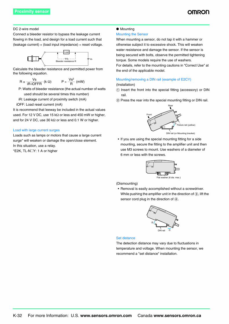
DC 2-wire model
Connect a bleeder resistor to bypass the leakage current
flowing in the load, and design for a load current such that
(leakage current) × (load input impedance) < reset voltage.
Calculate the bleeder resistance and permitted power from the following equation.
P: Watts of bleeder resistance (the actual number of watts
used should be several times this number)
iR: Leakage current of proximity switch (mA)
iOFF: Load reset current (mA)
It is recommend that leeway be included in the actual values
used. For 12 V DC, use 15 kΩ or less and 450 mW or higher,
and for 24 V DC, use 30 kΩ or less and 0.1 W or higher.
Load with large current surges
Loads such as lamps or motors that cause a large current
surge* will weaken or damage the open/close element.
In this situation, use a relay.
*E2K, TL-N@Y: 1 A or higher
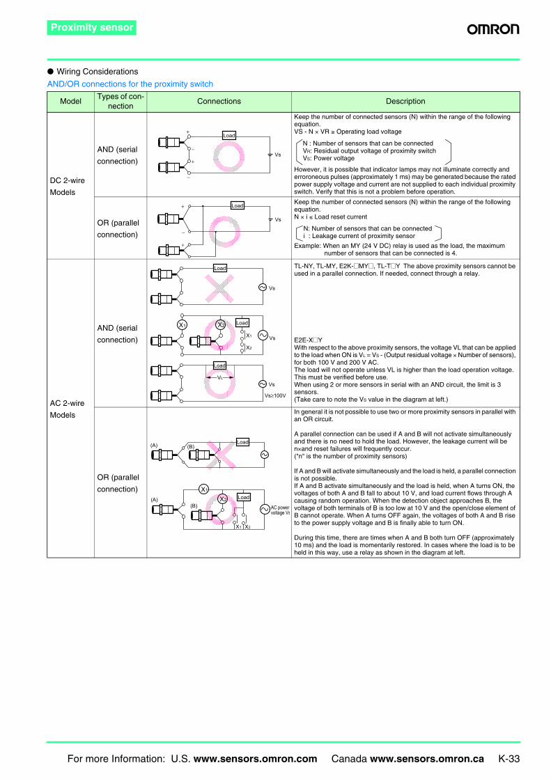
Mounting
Mounting the Sensor
When mounting a sensor, do not tap it with a hammer or
otherwise subject it to excessive shock. This will weaken
water resistance and damage the sensor. If the sensor is
being secured with bolts, observe the permitted tightening
torque. Some models require the use of washers.
For details, refer to the mounting cautions in "Correct Use" at
the end of the applicable model.
Mounting/removing a DIN rail (example of E2CY)
(Installation)
A Insert the front into the special fitting (accessory) or DIN
rail.
B Press the rear into the special mounting fitting or DIN rail.
• If you are using the special mounting fitting for a side
mounting, secure the fitting to the amplifier unit and then
use M3 screws to mount. Use washers of a diameter of
6 mm or less with the screws.
(Dismounting)
• Removal is easily accomplished without a screwdriver.
While pushing the amplifier unit in the direction of C, lift the
sensor cord plug in the direction of D.
Set distance
The detection distance may vary due to fluctuations in
temperature and voltage. When mounting the sensor, we
recommend a "set distance" installation.
R ≤Vs
(k Ω) P >Vs2
(mW)iR-iOFFR R
Vs
Load
Bleeder resistance R
Front
Rear
Fixture rail (yellow)
DIN rail (or Mounting bracket)
A
B
Flat washer (6 dia. max.)
DIN rail C
D
For more Information: U.S. www.sensors.omron.com Canada www.sensors.omron.ca K-33
Proximity sensor
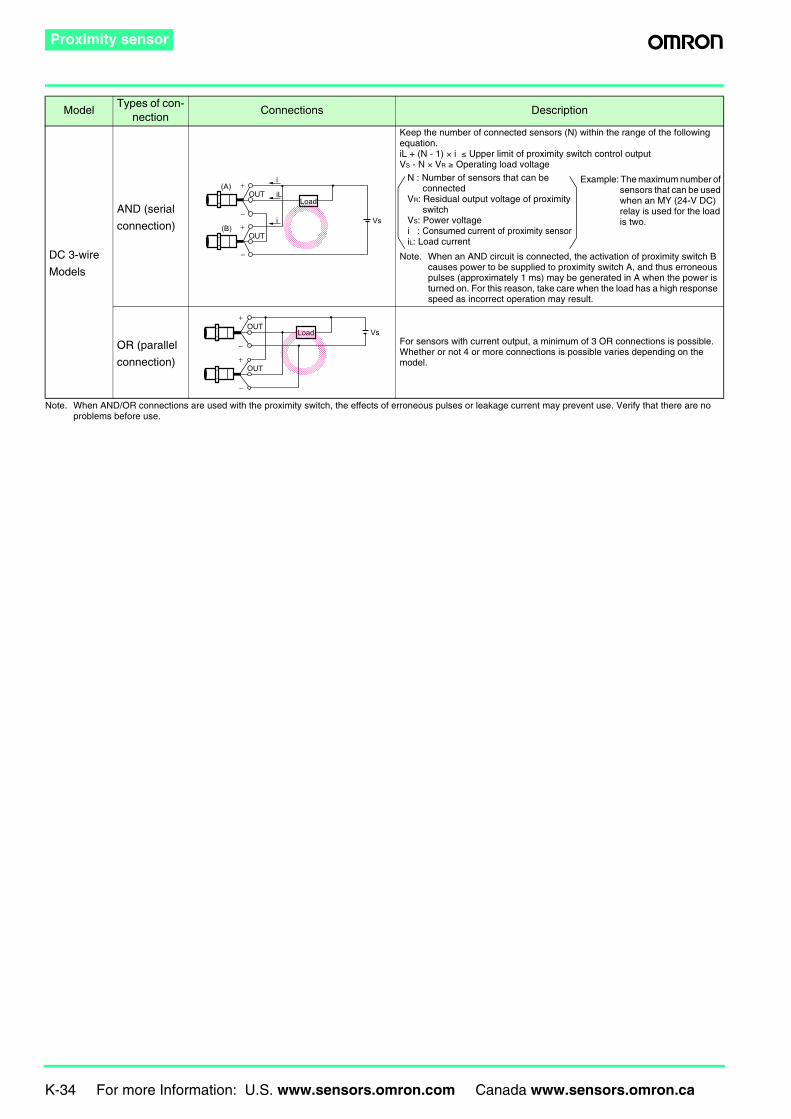
Wiring Considerations
AND/OR connections for the proximity switch
ModelTypes of con-
nectionConnections Description
DC 2-wire
Models
AND (serial
connection)
Keep the number of connected sensors (N) within the range of the following equation.VS - N × VR ≥ Operating load voltage
However, it is possible that indicator lamps may not illuminate correctly and erroroneous pulses (approximately 1 ms) may be generated because the rated power supply voltage and current are not supplied to each individual proximity switch. Verify that this is not a problem before operation.
OR (parallel
connection)
Keep the number of connected sensors (N) within the range of the following equation.N × i ≤ Load reset current
Example: When an MY (24 V DC) relay is used as the load, the maximum number of sensors that can be connected is 4.
AC 2-wire
Models
AND (serial
connection)
TL-NY, TL-MY, E2K-@MY@, TL-T@Y The above proximity sensors cannot be used in a parallel connection. If needed, connect through a relay.
E2E-X@YWith respect to the above proximity sensors, the voltage VL that can be applied to the load when ON is VL = VS - (Output residual voltage × Number of sensors), for both 100 V and 200 V AC.The load will not operate unless VL is higher than the load operation voltage. This must be verified before use.When using 2 or more sensors in serial with an AND circuit, the limit is 3 sensors.(Take care to note the VS value in the diagram at left.)
OR (parallel
connection)
In general it is not possible to use two or more proximity sensors in parallel with an OR circuit.
A parallel connection can be used if A and B will not activate simultaneously and there is no need to hold the load. However, the leakage current will be n×and reset failures will frequently occur.("n" is the number of proximity sensors)
If A and B will activate simultaneously and the load is held, a parallel connection is not possible.If A and B activate simultaneously and the load is held, when A turns ON, the voltages of both A and B fall to about 10 V, and load current flows through A causing random operation. When the detection object approaches B, the voltage of both terminals of B is too low at 10 V and the open/close element of B cannot operate. When A turns OFF again, the voltages of both A and B rise to the power supply voltage and B is finally able to turn ON.
During this time, there are times when A and B both turn OFF (approximately 10 ms) and the load is momentarily restored. In cases where the load is to be held in this way, use a relay as shown in the diagram at left.
Vs−
−
+
+Load
N : Number of sensors that can be connectedVR: Residual output voltage of proximity switchVS: Power voltage
−
+
+
Vs
Load
N: Number of sensors that can be connectedi : Leakage current of proximity sensor
Vs
VsX1
X2
X2X1
Vs≥100V
VL
Vs
Load
Load
Load
(B)
(B)
(A)
(A)
X1 X2
X2
X1
AC power voltage Vs
Load
Load
K-34 For more Information: U.S. www.sensors.omron.com Canada www.sensors.omron.ca
Proximity sensor
Note. When AND/OR connections are used with the proximity switch, the effects of erroneous pulses or leakage current may prevent use. Verify that there are no problems before use.
DC 3-wire
Models
AND (serial
connection)
Keep the number of connected sensors (N) within the range of the following equation.iL + (N - 1) × i ≤ Upper limit of proximity switch control outputVS - N × VR ≥ Operating load voltage
Note. When an AND circuit is connected, the activation of proximity switch B causes power to be supplied to proximity switch A, and thus erroneous pulses (approximately 1 ms) may be generated in A when the power is turned on. For this reason, take care when the load has a high response speed as incorrect operation may result.
OR (parallel
connection)
For sensors with current output, a minimum of 3 OR connections is possible.Whether or not 4 or more connections is possible varies depending on the model.
ModelTypes of con-
nectionConnections Description
(B)
(A)
Vs
i+
+
OUT
OUT
−
−
iL
i
Load
Example: The maximum number of sensors that can be used when an MY (24-V DC) relay is used for the load is two.
N : Number of sensors that can be connected
VR: Residual output voltage of proximity switch
VS: Power voltagei : Consumed current of proximity sensoriL: Load current
−
OUT
OUT
−
+
+
VsLoad
For more Information: U.S. www.sensors.omron.com Canada www.sensors.omron.ca K-35
Proximity sensor
Cable Length
The cable of a built-in amplifier models can be extended to a
maximum length of 200 m with each of the standard cables
(excluding some models).
For separate amplifier models (E2C-T11, E2C, E2J, E2CY,
F2LP), refer to the specific cautions.
Bending the cable
If you need to bend the cable, we recommend a bend radius
that is at least 3 times the outer diameter of the cable (with the
exception of coaxial and shielded cable).
Cable tension limits
In general, do apply a force greater than the values in the
following table.
Note. Note that shielded cable and coaxial cable must not be subjected to ten-sion.
Distinguishing high-voltage wire
Using metal conduit
If a power line lies near the proximity sensor cable, use
independent metal conduit to prevent incorrect operation or
damage.
(Same for DC Models.)
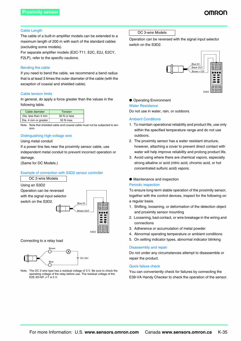
Example of connection with S3D2 sensor controller
Using an S3D2
Operation can be reversed
with the signal input selector
switch on the S3D2.
Connecting to a relay load
Note. The DC 2-wire type has a residual voltage of 3 V. Be sure to check the operating voltage of the relay before use. The residual voltage of the E2E-XD-M1 J-T is 5 V.
Operation can be reversed with the signal input selector
switch on the S3D2.
Operating Environment
Water Resistance
Do not use in water, rain, or outdoors.
Ambient Conditions
1. To maintain operational reliability and product life, use only
within the specified temperature range and do not use
outdoors.
2. The proximity sensor has a water resistant structure,
however, attaching a cover to prevent direct contact with
water will help improve reliability and prolong product life.
3. Avoid using where there are chemical vapors, especially
strong alkaline or acid (nitric acid, chromic acid, or hot
concentrated sulfuric acid) vapors.
Maintenance and inspection
Periodic inspection
To ensure long-term stable operation of the proximity sensor,
together with the control devices, inspect for the following on
a regular basis.
1. Shifting, loosening, or deformation of the detection object
and proximity sensor mounting
2. Loosening, bad contact, or wire breakage in the wiring and
connections
3. Adherence or accumulation of metal powder
4. Abnormal operating temperature or ambient conditions
5. On setting indicator types, abnormal indicator blinking
Disassembly and repair
Do not under any circumstances attempt to disassemble or
repair the product.
Quick failure check
You can conveniently check for failures by connecting the
E39-VA Handy Checker to check the operation of the sensor.
Cable diameter Tension
Dia. less than 4 mm 30 N or less
Dia. 4 mm or greater 50 N max.
DC 2-wire Models
5
2
4
1
6
3
11
8
10
7
12
9
Brown OUT
Blue 0V
S3D2
Blue
Brown
DC 24V
X
DC 3-wire Models
5
2
4
1
6
3
11
8
10
7
12
9Black OUTBlue 0V
Brown +12V
S3D2
K-36 For more Information: U.S. www.sensors.omron.com Canada www.sensors.omron.ca
Proximity sensor
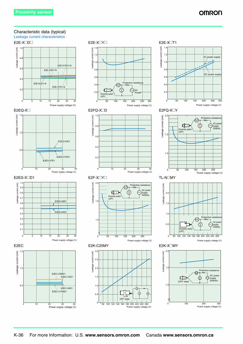
Characteristic data (typical)Leakage current characteristics
E2E-X@D@ E2E-X@Y@ E2E-X@T1
E2EQ-X@ E2FQ-X@D E2FQ-X@Y
E2ES-X@D1 E2F-X@Y@ TL-N@MY
E2EC E2K-C25MY E2K-X@MY
1.0
0.8
0.6
0.4
0.2
0 5 10 15 20 25 30
Power supply voltage (V)
Leak
age
curre
nt (m
A)
E2E-X10D1-N
E2E-X3D1-N
E2E-X7D1-NE2E-X2D1-N
Power supply voltage (V)
Leak
age
curre
nt (m
A) 1.4
1.2
1.0
0.8
0.6
0.4
0.2
0 50 100 150 200 250 300
mA
V ACPower
Protective resistance
Proximity switch (OFF)
1.4
1.2
1.0
0.8
0.6
0.4
0.2
0 50 100 150 200 250 300
Power supply voltage (V)
Leak
age
curre
nt (m
A)
AC power supply
DC power supply
E2EQ-X3D1
E2EQ-X10D1
E2EQ-X7D1
1.5
1.0
0.5
0 10 20Power supply voltage (V)
30 40
Leak
age
curre
nt (m
A)
Power supply voltage (V)
Leak
age
curre
nt (m
A) 1.0
0.8
0.6
0.4
0.2
0 10 20 30 40
Power supply voltage (V)
Leak
age
curre
nt (m
A) 2.0
1.5
1.0
0 50 100 150 200 250
mA
VAC power supply50/60Hz
Protective resistance
Proximity switch (OFF)
0 5 10 15 20 25 30
Power supply voltage (V)
Leak
age
curre
nt (m
A) 1.0
0.9
0.8
0.7
0.6
0.5
0.4
0.3
0.2
0.1
E2ES-X8D1
E2ES-X4D1
Power supply voltage (V)
Leak
age
curre
nt (m
A) 2.0
1.5
1.0
0 50 100 150 200 250
mA
VAC power supply50/60Hz
Protective resistance
Proximity switch (OFF)
0 80 100 120 140 160 180 200 220 240 260
Power supply voltage (V)
2.0
1.5
1.0
0.5
Leak
age
curre
nt (m
A)
mA
VAC power supply50/60Hz
Protective resistance
Proximity switch (OFF)
10 20 30 400
1.5
1.0
0.5
Power supply voltage (V)
E2EC-C1R5D1E2EC-X4D1
E2EC-C3D1E2EC-CR8D1Le
akag
e cu
rrent
(mA)
V
A
3.0
2.5
2.0
1.5
1.0
0.5
0
Leak
age
curre
nt (m
A)
80 100 120 140 160 180 200 220 240 260Power supply voltage (V)
OFF state
mA
V
2.0
1.5
1.0
Leak
age
curre
nt (m
A)
0 100 200 300Power supply voltage (V)
(OFF state)
Protective resistance
AC power supply50/60Hz
For more Information: U.S. www.sensors.omron.com Canada www.sensors.omron.ca K-37
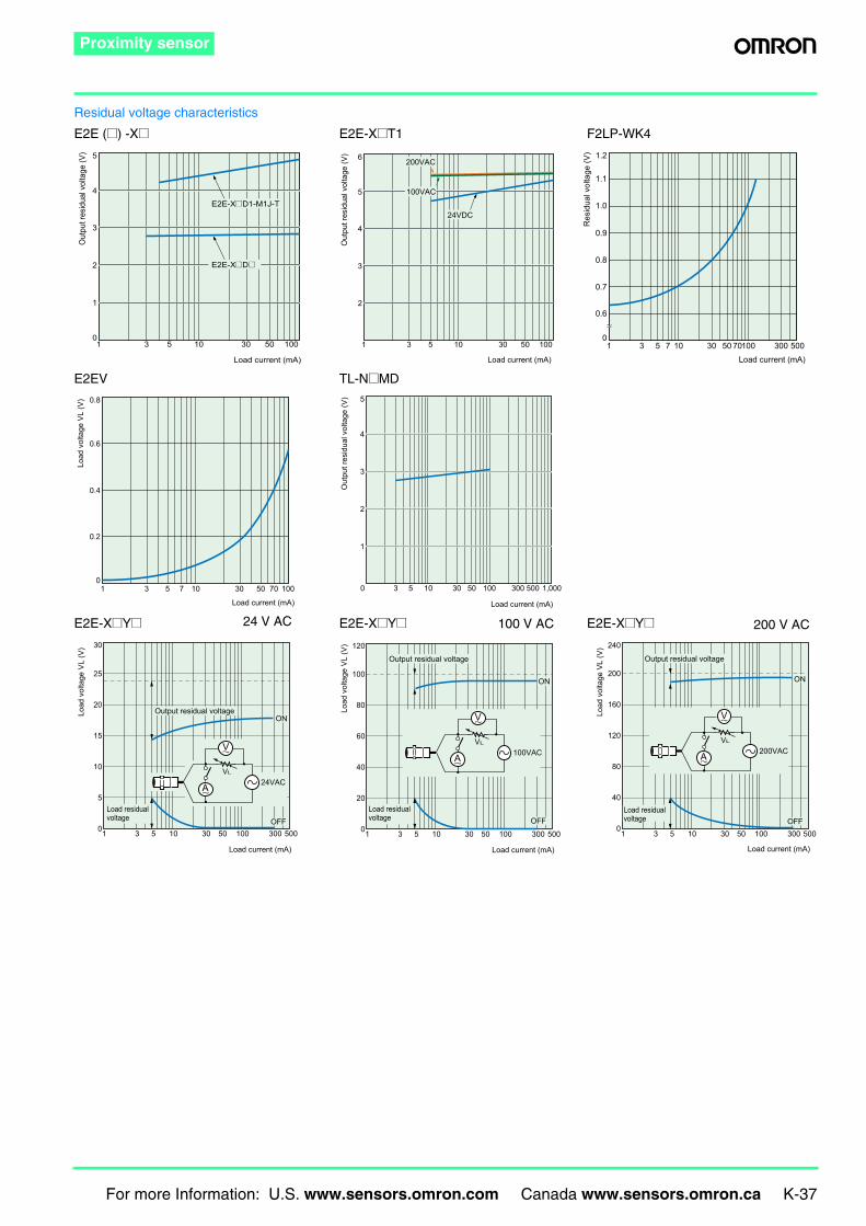
Proximity sensor
Residual voltage characteristics
E2E (@) -X@ E2E-X@T1 F2LP-WK4
E2EV TL-N@MD
E2E-X@Y@ E2E-X@Y@ E2E-X@Y@
1 3 5 10 30 50 100
Load current (mA)
5
4
3
2
1
0
Out
put r
esid
ual v
olta
ge (V
)
E2E-X@D1-M1J-T
E2E-X@D@
200VAC
100VAC
24VDC
1 3 5 10 30 50 100
Load current (mA)
6
5
4
3
2
O
utpu
t res
idua
l vol
tage
(V) 1.2
1.1
1.0
0.9
0.8
0.7
0.6
0
Res
idua
l vol
tage
(V)
1 3 5 7 10 30 50 70100 300 500Load current (mA)
0.8
0.6
0.4
0.2
0
Load
vol
tage
VL
(V)
1 3 5 7 10 30 50 70 100
Load current (mA)
0 3 5 10 30 50 100 300 500 1,000
Load current (mA)
Out
put r
esid
ual v
olta
ge (V
) 5
4
3
2
1
24 V AC 100 V AC 200 V AC
Load
vol
tage
VL
(V)
Load current (mA)
1 3 5 10 30 50 100 300 500
30
25
20
15
10
5
0
ON
OFFLoad residual voltage
Output residual voltage
A
V
VL
24VAC
Load
vol
tage
VL
(V)
Load current (mA)
1 3 5 10 30 50 100 300 500
120
100
80
60
40
20
0
Output residual voltage
Load residual voltage
ON
OFF
A
V
VL
100VAC
Load
vol
tage
VL
(V)
Load current (mA)
1 3 5 10 30 50 100 300 500
240
200
160
120
80
40
0
Output residual voltage
Load residual voltage
ON
OFF
A
V
VL
200VAC
K-38 For more Information: U.S. www.sensors.omron.com Canada www.sensors.omron.ca
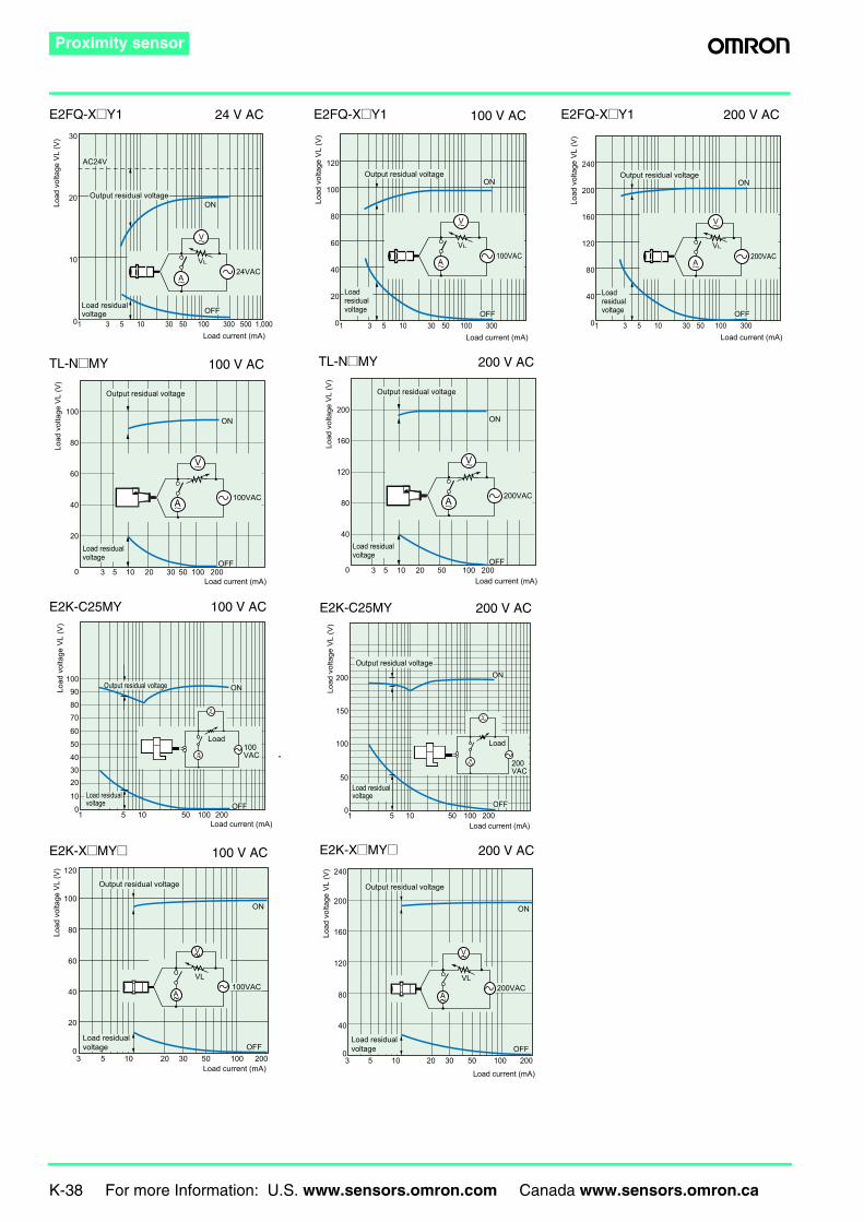
Proximity sensor
E2FQ-X@Y1 E2FQ-X@Y1 E2FQ-X@Y124 V AC 100 V AC 200 V AC
Load
vol
tage
VL
(V)
Load current (mA)1 3 5 10 30 50 100 300 500 1,000
30
20
10
0
AC24V
ON
OFFLoad residual voltage
Output residual voltage
A
V
VL
24VAC
Load
vol
tage
VL
(V)
Load current (mA)1 3 5 10 30 50 100 300
120
100
80
60
40
20
0
ON
OFF
Load residual voltage
Output residual voltage
A
V
VL
100VAC
Load
vol
tage
VL
(V)
Load current (mA)1 3 5 10 30 50 100 300
240
200
160
120
80
40
0
ON
OFF
Load residual voltage
Output residual voltage
A
V
VL
200VAC
100 V ACTL-N@MY
Load
vol
tage
VL
(V)
Load current (mA) 3 5 10 20 30 50 100 200
100
80
60
40
20
0
ON
OFF
Load residual voltage
Output residual voltage
A
V
100VAC
200 V ACTL-N@MY
Load
vol
tage
VL
(V)
Load current (mA) 3 5 10 20 50 100 200
200
160
120
80
40
0
ON
OFF
Load residual voltage
Output residual voltage
A
V
200VAC
100 V ACE2K-C25MY
V
A
Output residual voltage
Load residual voltage
Load100VAC
OFF
100908070
6050403020
100
Load
vol
tage
VL
(V)
1 5 10 50 100 200Load current (mA)
ON
200 V ACE2K-C25MY
V
A
Load
200VAC
OFF
Load residual voltage
Output residual voltageON
Load
vol
tage
VL
(V)
200
150
100
50
01 5 10 50 100 200Load current (mA)
100 V ACE2K-X@MY@
A
V
Output residual voltage
Load residual voltage
ON
OFF
100VAC
120
100
80
60
40
20
0
Load
vol
tage
VL
(V)
3 5 10 20 30 50 100 200Load current (mA)
VL
200 V ACE2K-X@MY@
A
V
Output residual voltage
Load residual voltage
ON
OFF
200VAC
240
200
160
120
80
40
0
Load
vol
tage
VL
(V)
3 5 10 20 30 50 100 200Load current (mA)
VL

MEMO
For more Information: U.S. www.sensors.omron.com Canada www.sensors.omron.ca K-39