event notification moduletm - schneider electric€¦ · update an alarm and event filter .....16...
TRANSCRIPT

Event Notification ModuleTM
User GuideVersion 7.0
63220-083-01A308/2012

Event Notification Module 63220-083-01A308/2012
© 2012 Schneider Electric. All Rights Reserved.2
Notices
StruxureWare, StruxureWare Power Monitoring, PowerLogic, Citect, and Schneider Electric are either trademarks or registered trademarks of Schneider Electric in France, the USA, and other countries. All other trademarks are property of their respective owners.

63220-083-01A3 08/2012
© 2012 Schneider Electric. All Rights Reserved. 3
Safety Information
Important InformationRead these instructions carefully and look at the equipment to become familiar with the device before trying to install, operate, service or maintain it. The following special messages may appear throughout this manual or on the equipment to warn of potential hazards or to call attention to information that clarifies or simplifies a procedure.
The addition of either symbol to a “Danger” or “Warning” safety label indicates that an electrical hazard exists which will result in personal injury if the instructions are not followed.
This is the safety alert symbol. It is used to alert you to potential personal injury hazards. Obey all safety messages that follow this symbol to avoid possible injury or death.
Please NoteElectrical equipment should be installed, operated, serviced and maintained only by qualified personnel. No responsibility is assumed by Schneider Electric for any consequences arising out of the use of this material.
A qualified person is one who has skills and knowledge related to the construction, installation, and operation of electrical equipment and has received safety training to recognize and avoid the hazards involved.
DANGERDANGER indicates an imminently hazardous situation which, if not avoided, will result in death or serious injury.
WARNINGWARNING indicates a potentially hazardous situation which, if not avoided, can result in death or serious injury.
CAUTIONCAUTION indicates a potentially hazardous situation which, if not avoided, can result in minor or moderate injury.
NOTICE, is used to address practices not related to physical injury. The safety alert symbol shall not be used with this signal word.

Event Notification Module 63220-083-01A308/2012
© 2012 Schneider Electric. All Rights Reserved.4

63220-083-01A3 Table of Contents08/2012
© 2012 Schneider Electric All Rights Reserved 5
CHAPTER 1 - OVERVIEW About Event Notification Module and Alarm Sentry .................................... 7Overview .................................................................................................. 7Technical Considerations ........................................................................ 8Support Contacts ..................................................................................... 8
CHAPTER 2 - SETTING UP EVENT NOTIFICATION MODULE
Add local users to Event Notification Module groups .................................. 9Set up local users .................................................................................... 9Assign local users to a group ................................................................. 10
Start Event Notification Module ................................................................. 10Set up OPC alarm and event server connections ..................................... 11
Auto-detect OPC alarm and event servers ............................................ 12Register the OPC alarm and event server manually ............................. 13Update Event Notification Module with server changes ........................ 13
Configure alarm and event filtering ........................................................... 14Add a new alarm and event filter ........................................................... 15Update an alarm and event filter ............................................................ 16Remove an alarm and event filter .......................................................... 16
Identify recipients and define relay attributes ............................................ 17Add and configure recipients and relay attributes .................................. 17Modify a recipient and relay attributes ................................................... 18Delete a recipient and relay ................................................................... 18
Define message schedules for recipients ................................................. 19Subscribe recipients to receive alarms ..................................................... 21
Subscribe a recipient ............................................................................. 21Edit a subscription for alarm notifications .............................................. 22Delete a subscription for alarm notifications .......................................... 22
Define maintenance mode groups (optional) ............................................ 22Add maintenance mode groups ............................................................. 22
Subscribe a recipient ................................................................................. 24Edit a subscription for maintenance mode notifications ......................... 25Delete a subscription for maintenance mode notifications .................... 25
Start and stop Event Notification Module services (Administrative) .......... 26Define relay message templates (optional) ............................................... 27
Add and configure relay templates ........................................................ 27Modify a relay template .......................................................................... 29Delete a relay template .......................................................................... 29
Define messages for relay notifications (optional) .................................... 29Standard OPC attributes ........................................................................ 30Custom OPC attributes .......................................................................... 30
CHAPTER 3 - SETTING UP ALARM SENTRY
Start Alarm Sentry ..................................................................................... 33Configure the source for OPC DA tags ..................................................... 34Filter the grid data ..................................................................................... 36Configure analog and digital alarms .......................................................... 37
Select the server with DA Tag sources .................................................. 38Define the alarm for one DA tag at a time ............................................. 39Define alarms for multiple DA Tags with a template .............................. 40
Configure advanced alarms ...................................................................... 43Select the server with the DA Tag sources ............................................ 43Create and verify the alarm expression ................................................. 44
Configure the TAG OPC DA/AE Server .................................................... 46Configure DCOM for the TAG OPC DA/AE Server ............................... 46
Update ENM with the Alarm Sentry server ............................................... 47Stop the OPC Logger and ENM services .............................................. 47Configure the OPC Server in Event Notification Module ....................... 48Restart the OPC Logger and ENM services .......................................... 49

Table of Contents 63220-083-01A308/2012
© 2012 Schneider Electric All Rights Reserved6
CHAPTER 4 - EVENT NOTIFICATION MODULE CONTROL
Change the status of maintenance mode groups ......................................51
CHAPTER 5 - EVENT NOTIFICATION MODULE MONITORING
View live monitoring data ..........................................................................53View historical monitoring data ..................................................................54
Use basic filtering ...................................................................................54Use advanced filtering ...........................................................................55
Export to spreadsheet ...............................................................................56Configure monitoring options ....................................................................57
CHAPTER 6 - EVENT NOTIFICATION MODULE DIAGNOSTICS VIEWER
View live diagnostics data .........................................................................59View historical diagnostics data ................................................................60
Use basic filtering ...................................................................................60Use advanced filtering ...........................................................................61Export to spreadsheet ............................................................................61
Configure diagnostic options .....................................................................62
CHAPTER 7 - RESOLVE ISSUES
Problems and Resolutions ........................................................................63
CHAPTER 8 - RELAY ATTRIBUTE DEFINITIONS
Definitions ..................................................................................................65Attributes ...................................................................................................65
CHAPTER 9 - OPC AE SERVER FOR PLSCADA
Installation .................................................................................................69Citect Configuration ...................................................................................69
CHAPTER 10 - DATABASE MAINTENANCE UTILITY
SQL Scripts and Windows Tasks ..............................................................71
CHAPTER 11 - HOT STANDBY CONFIGURATION
Prerequisites .............................................................................................73Configure ENM on the Primary Server ......................................................73Configure ENM on the Secondary Server .................................................75Configure PLSCADA Servers for Hot-Standby Operation .........................76
Share server folders ...............................................................................76Configure Citect Software ......................................................................77
Troubleshooting Citect Setup ....................................................................81Citect INI file settings .............................................................................81Citect-Regkey entry ...............................................................................81Server switching delays .........................................................................81

63220-083-01A3 08/2012
© 2012 Schneider Electric All Rights Reserved 7
Chapter 1 — Overview
About Event Notification Module and Alarm Sentry
NoteOther parts of the overall communication system, such as email servers and cellular phone systems, could fail and result in notifications not being delivered. If notifications are not delivered to recipients, conditions that cause alarming may persist and result in safety critical issues.
Overview
The Event Notification Module (ENM) provides a way for you to make sure the specified people in your facility are notified about critical power incidents no matter where they are. ENM delivers timely alerts of power system events to the mobile phone, email or pager of designated users and helps them quickly identify system abnormalities and take appropriate action.
Event Notification Module provides:
• Flexible alarm notifications schedules• Multiple notification options• Alarm grouping• Alarm consolidation• Simple commissioning • Maintenance mode
WARNING
HAZARD OF UNDELIVERED NOTIFICATIONSDo not rely solely on Event Notification Module software for alarm notifications where human or equipment safety relies on successfully delivered notifications.
Failure to follow these instructions can result in death, serious injury, or equipment damage.
WARNING
HAZARD OF UNINTENDED OPERATIONDo not use Event Notification Module software for critical control or protection applications where human or equipment safety relies on the operation of the control circuit.
Failure to follow these instructions can result in death, serious injury, or equipment damage.

Chapter 1—Overview 63220-083-01A3About Event Notification Module and Alarm Sentry 08/2012
© 2012 Schneider Electric All Rights Reserved8
Technical Considerations
The core function of the ENM is alarm notification. ENM accepts alarms through OPC Alarm and Event (AE) servers and PowerLogic™ SCADA servers and notifies the specified user based on the configured notification options and alarm schedule.
ENM also includes the Alarm Sentry component. Alarm Sentry extends the standard notification features of ENM with alarm evaluation capabilities. Alarm Sentry can generate alarms on data from an ION Enterprise 6.0.1 system and from a StruxureWare™ Power Monitoring™(SPM) 7.0 or 7.0.1 system. Alarm Sentry accepts data through an OPC Data Acquisition (DA) server and evaluates the alarm conditions. If an alarm occurs, Alarm Sentry passes the event to the ENM notification engine.
The following chapters explain how to configure the core ENM features as well as the Alarm Sentry and OPC Server components. Each of these components plays an important part in providing a complete alarm evaluation and notification solution.
Support Contacts
Support for solutions is provided by Solutions Customer Support centers. All customer issues must be reported to one of these channels:
Phone:
• NAOD: +1 615-287-3400 (7:30 AM – 7:00 PM US-Central Time)• EMEAS: +420 281 088 660 (8:30 AM – 5:30 PM Central Europe Time)• APOD: +86 10 6503 7788 (8:30 AM – 5:30 PM China Standard Time)
Email: [email protected]
Pl@net: http://planet.schneider-electric.com/

63220-083-01A3 08/2012
© 2012 Schneider Electric All Rights Reserved 9
Chapter 2 — Setting up Event Notification Module
This chapter describes how to set up Event Notification Module (ENM) to receive alarms and events and to transmit them to recipients via email, SMS text messages, and other methods.
The setup of ENM involves the following tasks.
1. Add local users to ENM groups.2. Start the ENM web setup application.3. Set up OPC alarm and event server connections.4. Configure alarm and event filtering from various OPC alarm and event servers.5. Identify recipients and how they should be notified.6. Define the schedule for each recipient to receive alarm messages.7. Subscribe recipients to receive alarms and maintenance mode notifications.You can also complete these optional setup tasks:
• Create maintenance mode groups, which are required to set up maintenance subscriptions for nodes. Once a node or a group of nodes is placed in maintenance mode, ENM does not send alarms from these nodes.
• Create templates to define message transmission characteristics for relays, such as email or SMS text messages.
• Create messages for relay notifications sent to recipients.
NOTE: When using Internet Explorer 8, Compatibility Mode must be enabled. If not enabled, some ENM functionality will not be available. ENM does not work with Internet Explorer 9.
Add local users to Event Notification Module groups
The following sections explain how to set up the necessary ENM user groups. You can add local users to these ENM groups:
• ENMAdmin - The group has full rights to the setup. monitoring, and diagnostics areas. This group also has rights for the Alarm Sentry setup.
• ENMControl - The group has rights to the monitoring, diagnostics, and the control areas.• ENMUser - The group has rights to the monitoring and diagnostics areas only.
NOTE: Only ENM Administrators have access to the Setup page. To configure an ENM application, administrative privileges must be established by adding the user to the ENMAdmin group.
NOTE: This section explains how to set up local users only, not domain users.
Set up local users
Use Computer Management to add new users for ENM.
1. In Windows Control Panel, open Administrative Tools > Computer Management. The Computer Management screen appears.
2. In the Computer Management tree view, click System Tools > Local Users & Groups. The Users and Groups folder appear in the tree view.

Chapter 2—Setting up Event Notification Module 63220-083-01A3Start Event Notification Module 08/2012
© 2012 Schneider Electric All Rights Reserved10
3. Right-click the Users folder and select the New User command. The New User screen appears.
4. Enter the User Name, Full Name, and Description. 5. Enter the user’s password. 6. Click Create, and then click Close.
Assign local users to a group
After you add a local user to the system, you can assign the user to either ENMAdmin, ENMControl, or ENMUser account. The same user can be assigned to all three accounts.
1. In the Computer Management tree view, click Groups folder. The system group names appear in the list.
2. Double-click either ENM group to assign local user to that group. The group Properties screen appears.
3. Click Add. The Select User screen appears.4. Select the local users you want to add to this group.5. Click OK. The group Properties screen appears.6. Click Apply, and then click OK.
Start Event Notification Module
If the Event Notification Module web page is not open, then open it as follows.
1. In Windows, go to Start > All Programs > Schneider Electric > StruxureWare Solutions > Event Notification. You can also use the Desktop shortcut icon. The Event Notification Module home page appears.

63220-083-01A3 Chapter 2—Setting up Event Notification Module08/2012 Set up OPC alarm and event server connections
© 2012 Schneider Electric All Rights Reserved 11
2. To set up the ENM application, click Setup > ENM Setup in the toolbar.The Setup menu appears.
3. In the Setup menu, click the menu name or the arrows to see the command links.The following sections describe the required and optional tasks for configuring ENM.
Set up OPC alarm and event server connections
On the OPC Server Configuration page you set up communication between the ENM and the OPC Alarm and Event Servers on the data network.
You can let ENM automatically detect available OPC servers and select the server you want to use. You can also enter a specific OPC server on a server machine.

Chapter 2—Setting up Event Notification Module 63220-083-01A3Set up OPC alarm and event server connections 08/2012
© 2012 Schneider Electric All Rights Reserved12
Auto-detect OPC alarm and event servers
Follow these steps if you want to let ENM automatically detect OPC servers.
1. On the Setup menu, click OPC Server > Edit. The OPC Server Configuration page appears.
If OPC servers are available on the local host, they will automatically appear in the Available Servers box. Skip to step 4. If the OPC server is on a different server machine, use the following steps.
2. Under Available OPC Servers, type the computer name in the Machine box.3. Click Auto-detect OPC Servers.
If OPC alarm and event servers are registered on the specified computer, then the server names appear in the Available Servers box.
4. In the Available Servers box, click a server name and then click > to move the server to the Selected Servers box.You can also click >> to move all servers to the Selected Servers box.
5. Click Apply Changes to register the servers.

63220-083-01A3 Chapter 2—Setting up Event Notification Module08/2012 Set up OPC alarm and event server connections
© 2012 Schneider Electric All Rights Reserved 13
Register the OPC alarm and event server manually
Follow these steps if you want to manually select an OPC server.
1. On the Setup menu, click OPC Server > Edit. The OPC Server Configuration page appears.
2. Under Manual Entry, type the computer host name or IP address in the Machine box.3. Type the server name in the OPC Server box.4. Click Verify to make sure the server is on the network.
If the server is available, a message appears to confirm the connection.
5. Click Add to insert the server into the Selected Servers box.6. Click Apply Changes to save the configuration.
Update Event Notification Module with server changes
At a later time, changes may be made to the settings on an OPC server. ENM does not automatically detect those changes. You must return to the OPC Server Configuration page and apply the changes.
For example, you add a PowerLogic SCADA OPC server to the Selected Servers box and that server currently has a disabled alarm. Later, the alarm on that server is enabled. You must click Apply Changes to make sure ENM detects the now-enabled alarm on the server.
You must also open the Preferences page and restart the OPC logger and ENM services. See “Start and stop Event Notification Module services (Administrative)” on page 26 for instructions.
Chapter 2—Setting up Event Notification Module 63220-083-01A3Configure alarm and event filtering 08/2012
© 2012 Schneider Electric All Rights Reserved14
Configure alarm and event filtering
ENM streamlines the management of alarms with alarm grouping functionality called filters. By default, each new OPC server connected to ENM has a filter set up that includes all its alarms, the “ALL” filter.
However, it often makes sense to define new filters to simplify:
• Sending alarms from different devices to different users • Using a different notification method for lower priority alarms• Filtering out alarms on the OPC server that are not important
When ENM receives an alarm that matches the filter and if the delay is anything greater than 0, it does the following:
• ENM sends a notification, indicating it is aggregating the alarms, and identifies which alarms triggered the aggregation.
• At the end of the delay, ENM sends another notification, summarizing the received alarms.
If the delay is zero, the system sends a notification for every alarm that is received.
On the Filter Configuration page you can create an alarm and event filter that defines a group of alarms. You can define specific filters to process alarms from different servers and nodes.
The “ALL” filter is a default filter assigned to each OPC server. This filter includes all alarms from all nodes.

63220-083-01A3 Chapter 2—Setting up Event Notification Module08/2012 Configure alarm and event filtering
© 2012 Schneider Electric All Rights Reserved 15
Add a new alarm and event filter
Follow these steps to add a new alarm and event filter.
1. On the Setup menu, click Filter > Edit. The Filter Configuration page with the “ALL” filter appears.
2. Under Select Filter, select the server in the Servers box.3. Click Add New Filter. A new filter is created with “New Filter” as the default name. 4. In the Name box, type over the default name and enter a descriptive name.5. In the Severity Filter boxes, enter the range of alarms and events to be received.
NOTE: If you are unfamiliar with the alarm severity level, please contact the system administrator.
6. (Optional) Type an integer value in the Delay in Seconds box. This option prevents a flood of notifications from events that trigger many alarms very quickly. For example, if a main drops out, hundreds of alarms are produced within a few seconds. Recipients do not want to receive a notification for each alarm. This option tells ENM to wait and see if other alarms come in rapidly. If so, then ENM aggregates the alarms into one message.
7. (Optional) In the Delay Start Messages box, type the message you want to include in the alarm notification.
8. In the Available Nodes box, select the server nodes from where you want to receive alarms.
9. Click Save Filter to save the new filter. 10. Click OK in the confirmation message.
Repeat steps 3 – 9 to add more filters for the same server.
Repeat steps 2 – 9 to add filters for a different server.
Chapter 2—Setting up Event Notification Module 63220-083-01A3Configure alarm and event filtering 08/2012
© 2012 Schneider Electric All Rights Reserved16
Update an alarm and event filter
After the new filter is saved, you can change the server nodes for the filter at any time. You do not have to click Save Filter after changing the nodes.
If you change other details for the filter, you must click Save Filter to save the changes.
Remove an alarm and event filter
You can remove an alarm and event filter when the filter is no longer necessary.
1. On the Setup menu, click Filter > Edit. The Filter Configuration page appears.2. Under Select Filter, select the server in the Servers box.3. In the Filters box, select the filter you want to delete.4. Click Remove Filter.5. In the confirmation message, click OK.

63220-083-01A3 Chapter 2—Setting up Event Notification Module08/2012 Identify recipients and define relay attributes
© 2012 Schneider Electric All Rights Reserved 17
Identify recipients and define relay attributes
ENM supports several methods, called relays, to send alarm and event notifications to a person or recipient. On the Relay and Recipient Configuration page, you can identify recipients who will receive alarm and event messages and define their relay attributes.
Before you start adding new recipients, it is helpful to create a template for the relays you want to use. Many of the fields you need to provide for a particular relay will be the same for all recipients who use that relay. The template represents initial values for the relay attributes. After you select the template, you can modify the unique details for each recipient. See “Define relay message templates (optional)” on page 27 for details.
Add and configure recipients and relay attributes
In ENM, a recipient can receive notifications through multiple relays. Follow these steps to define the recipients and associated relays.
1. On the Setup menu, click Relay & Recipient > Edit. The Relay and Recipient Configuration page appears.
2. Under Recipient, click Add. In the popup screen, type the recipient's name and description, and then click Apply.
3. In the Relay Name box, select the relay you want to configure for this recipient. The attributes for this relay appear in the grid. The values in the data column are default values or indicate the correct format.

Chapter 2—Setting up Event Notification Module 63220-083-01A3Identify recipients and define relay attributes 08/2012
© 2012 Schneider Electric All Rights Reserved18
4. If templates are defined and you want to use a template:a. Select the matching template in the Relay Template box.b. In the confirmation message, click OK. The fields in the data column get populated
from the template.
5. Under Configuration, enter the data for each attribute in the left column:a. Click the data field in the right column for an attribute.b. In the data entry box, enter text or select an option, and then click OK.c. Continue these steps for each attribute you want to enter for this template.d. See Chapter 8—Relay Attribute Definitions for more information about the attributes.
NOTE: The value for an attribute must not exceed 500 characters, including spaces.
The changes you make for the relay configuration are saved automatically.
Repeat steps 3 – 5 to configure a different relay for the same recipient.
Repeat steps 2 – 5 to configure relays for another recipient.
Modify a recipient and relay attributes
You can change details about a relay recipient, such as recipient name and relay attributes. Any changes you make are saved automatically.
1. On the Setup menu, click Relay & Recipient > Edit. The Relay and Recipient Configuration page appears.
2. Under Recipient, click Edit. In the dialog box, change the recipient's name and description, and then click Apply.
3. In the Relay Name box, select the relay you want to change. The attributes for this relay appear in the grid.
4. Click an attribute field and modify the value.
Delete a recipient and relay
You can delete recipients from the system at any time. The relay attributes for the deleted recipient are also removed.
1. On the Setup menu, click Relay & Recipient > Edit. The Relay and Recipient Configuration page appears.
2. Under Recipient, click Delete.3. In the confirmation message, click OK.
The recipient and associated attributes are removed from the application.

63220-083-01A3 Chapter 2—Setting up Event Notification Module08/2012 Define message schedules for recipients
© 2012 Schneider Electric All Rights Reserved 19
Define message schedules for recipients
For each recipient you entered previously, you can define a schedule for when that person will receive alarm and event messages.
The Schedules page defines the times during a seven-day week when recipients can receive messages from ENM. You can define a different schedule on each day of the week, if necessary. For example, the recipient can accept messages Monday through Wednesday between 7:00 AM and 7:00 PM, and Friday through Saturday between 10:00 AM and 10:00 PM.
1. On the Setup menu, click Schedule > Edit. The Schedules page appears.
2. In the Recipients box, select the recipient.3. Click Add. A data row appears in the grid with default values.
4. Click the check box in each day column to check or uncheck the cell.5. Click the Start Time or End Time cell and type the correct time range for the recipient.6. Press the TAB key to access the change.7. Note the following details about the time range cells:
• Start Time – The earliest time you can enter is 12:00 AM.• End Time – The latest time you can enter is 11:59 PM.• One schedule row can accommodate any time range from 12:00 AM to 11:59 PM on
the same calendar day.

Chapter 2—Setting up Event Notification Module 63220-083-01A3Define message schedules for recipients 08/2012
© 2012 Schneider Electric All Rights Reserved20
• If the schedule starts on one day and continues past midnight until the next day, you must enter two rows for the schedule, as shown next:
Scheduling changes are saved automatically.
Repeat steps 3 – 5 to add a different schedule for the same recipient. You can add multiple rows, each with a different schedule, to define the exact schedule required for the recipient.
Repeat steps 2 – 6 to enter a schedule for a different recipient.

63220-083-01A3 Chapter 2—Setting up Event Notification Module08/2012 Subscribe recipients to receive alarms
© 2012 Schneider Electric All Rights Reserved 21
Subscribe recipients to receive alarms
On the Alarm and Event Notification Subscription page you specify which alarm groups (filters) are assigned to a recipient and how those alarms are sent. For each recipient, you select the OPC server, filter definition, and relay type. You can define multiple subscriptions for a recipient.
Subscribe a recipient
1. On the Setup screen, click Subscription > AE Subscription. The Alarm and Event Notification Subscription screen appears.
2. In the grid, click Add. A blank data row appears in the grid.3. Click the Edit Row icon next to the blank row. The details screen appears.
4. Select the recipient name, server, and other details for this subscription.5. (Optional) Check the Get Server Pings option if you want ENM to send regular
notifications during long periods of inactivity. The default is one hour. If this duration should be changed, contact Technical Support.
6. Click OK. The subscription details appear in the grid.Repeat steps 2 – 6 to subscribe the same recipient to other OPC servers or configure subscriptions for other recipients.
Chapter 2—Setting up Event Notification Module 63220-083-01A3Define maintenance mode groups (optional) 08/2012
© 2012 Schneider Electric All Rights Reserved22
Edit a subscription for alarm notifications
You can change details for a subscription when necessary.
1. On the Setup screen, click Subscription > AE Subscription. The Alarm and Event Notification Subscription screen appears.
2. Click the edit icon next to the row you want to edit. The subscription details screen appears.
3. Change any details as necessary.4. Click OK.
The subscription details appear in the grid.
Delete a subscription for alarm notifications
When a subscription is no longer needed, you can remove it from the system.
1. On the Setup screen, click Subscription > AE Subscription. The Alarm and Event Subscription Notification screen appears.
2. Click the delete icon next to the row you want to remove.
The data row gets deleted from the grid.
Define maintenance mode groups (optional)
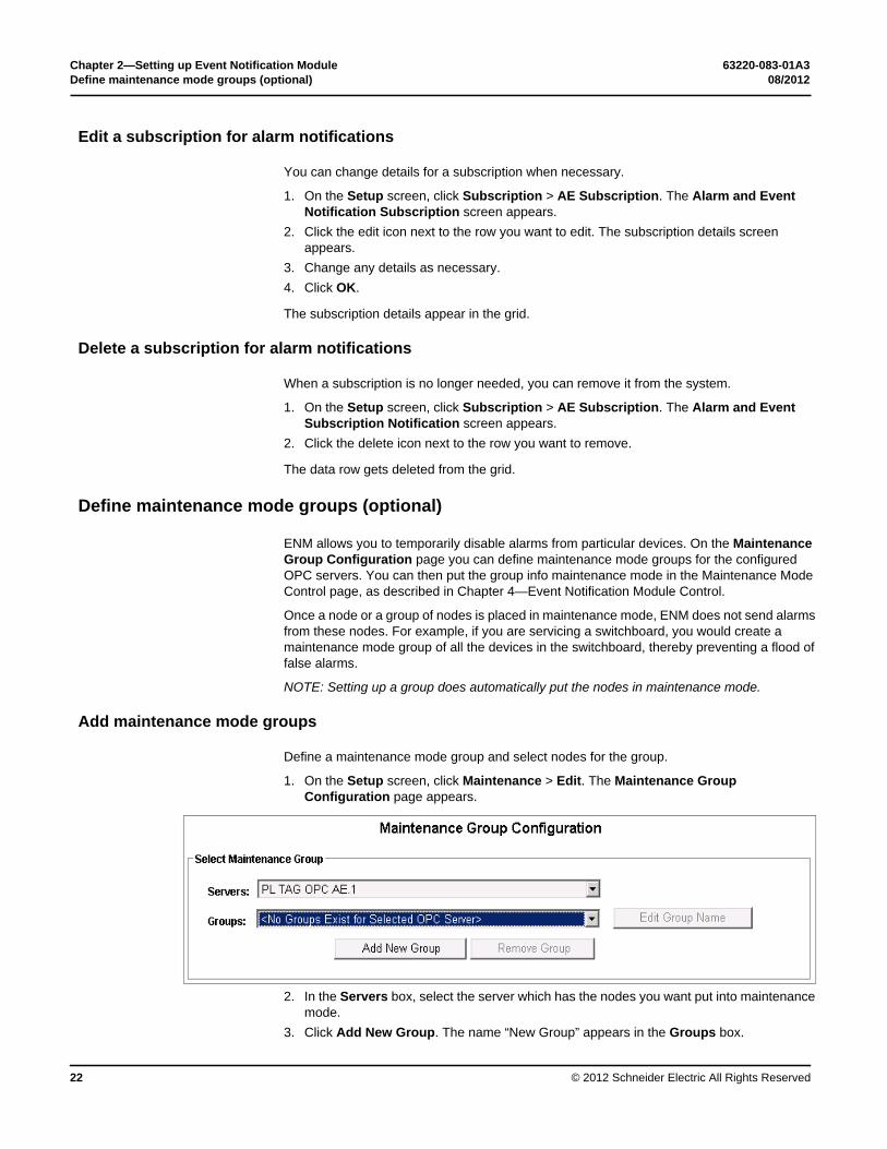
ENM allows you to temporarily disable alarms from particular devices. On the Maintenance Group Configuration page you can define maintenance mode groups for the configured OPC servers. You can then put the group info maintenance mode in the Maintenance Mode Control page, as described in Chapter 4—Event Notification Module Control.
Once a node or a group of nodes is placed in maintenance mode, ENM does not send alarms from these nodes. For example, if you are servicing a switchboard, you would create a maintenance mode group of all the devices in the switchboard, thereby preventing a flood of false alarms.
NOTE: Setting up a group does automatically put the nodes in maintenance mode.
Add maintenance mode groups
Define a maintenance mode group and select nodes for the group.
1. On the Setup screen, click Maintenance > Edit. The Maintenance Group Configuration page appears.
2. In the Servers box, select the server which has the nodes you want put into maintenance mode.
3. Click Add New Group. The name “New Group” appears in the Groups box.

63220-083-01A3 Chapter 2—Setting up Event Notification Module08/2012 Define maintenance mode groups (optional)
© 2012 Schneider Electric All Rights Reserved 23
4. Click Edit Group Name to change the name.5. Under Available Nodes, click [+] to expand the nodes under the server.6. Click the check box to select the nodes to include in the group.
7. Click Save Configuration.8. In the confirmation message, click OK.
Repeat steps 3 – 8 to define another group on the same server.
Repeat steps 2 – 8 to define maintenance mode groups on a different server.

Chapter 2—Setting up Event Notification Module 63220-083-01A3Subscribe a recipient 08/2012
© 2012 Schneider Electric All Rights Reserved24
Subscribe a recipient
A recipient subscribed to a maintenance mode group is notified through the selected relay any time the group is enabled and alarms from those devices will be suppressed.
1. On the Setup screen, click Subscription > MM Subscription. The Maintenance Mode Subscription Notification screen appears.
2. In the grid, click Add. A blank data row appears in the grid.3. Click the edit icon next to the blank row. The subscription details screen appears.
4. Select the recipient name, server, and other details for this subscription.5. Click OK. The subscription details appear in the grid.
Repeat steps 2 – 5 to subscribe the same recipient to other OPC servers or configure subscriptions for other recipients.

63220-083-01A3 Chapter 2—Setting up Event Notification Module08/2012 Subscribe a recipient
© 2012 Schneider Electric All Rights Reserved 25
Edit a subscription for maintenance mode notifications
1. On the Setup screen, click Subscription > MM Subscription. The Maintenance Mode Subscription Notification screen appears.
2. Click the edit icon next to the row you want to edit. The subscription details screen appears.
3. Change the details for this subscription.4. Click OK.
Delete a subscription for maintenance mode notifications
1. On the Setup screen, click Subscription > MM Subscription. The Maintenance Mode Subscription Notification screen appears.
2. Click the delete icon next to the row you want to remove.
Chapter 2—Setting up Event Notification Module 63220-083-01A3Start and stop Event Notification Module services (Administrative) 08/2012
© 2012 Schneider Electric All Rights Reserved26
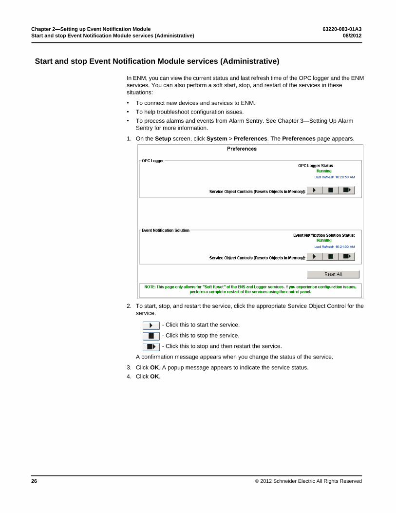
Start and stop Event Notification Module services (Administrative)
In ENM, you can view the current status and last refresh time of the OPC logger and the ENM services. You can also perform a soft start, stop, and restart of the services in these situations:
• To connect new devices and services to ENM.• To help troubleshoot configuration issues.• To process alarms and events from Alarm Sentry. See Chapter 3—Setting Up Alarm
Sentry for more information.
1. On the Setup screen, click System > Preferences. The Preferences page appears.
2. To start, stop, and restart the service, click the appropriate Service Object Control for the service.
- Click this to start the service.
- Click this to stop the service.
- Click this to stop and then restart the service.
A confirmation message appears when you change the status of the service.
3. Click OK. A popup message appears to indicate the service status. 4. Click OK.
63220-083-01A3 Chapter 2—Setting up Event Notification Module08/2012 Define relay message templates (optional)
© 2012 Schneider Electric All Rights Reserved 27
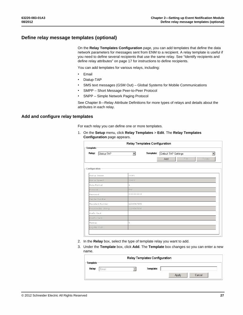
Define relay message templates (optional)
On the Relay Templates Configuration page, you can add templates that define the data network parameters for messages sent from ENM to a recipient. A relay template is useful if you need to define several recipients that use the same relay. See “Identify recipients and define relay attributes” on page 17 for instructions to define recipients.
You can add templates for various relays, including:
• Email• Dialup-TAP• SMS text messages (GSM Out) – Global Systems for Mobile Communications• SMPP – Short Message Peer-to-Peer Protocol• SNPP – Simple Network Paging Protocol
See Chapter 8—Relay Attribute Definitions for more types of relays and details about the attributes in each relay.
Add and configure relay templates
For each relay you can define one or more templates.
1. On the Setup menu, click Relay Templates > Edit. The Relay Templates Configuration page appears.
2. In the Relay box, select the type of template relay you want to add.3. Under the Template box, click Add. The Template box changes so you can enter a new
name.
Chapter 2—Setting up Event Notification Module 63220-083-01A3Define relay message templates (optional) 08/2012
© 2012 Schneider Electric All Rights Reserved28
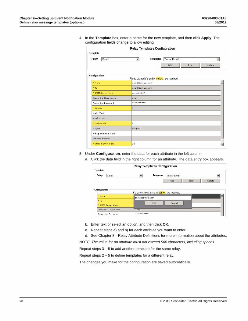
4. In the Template box, enter a name for the new template, and then click Apply. The configuration fields change to allow editing.
5. Under Configuration, enter the data for each attribute in the left column:a. Click the data field in the right column for an attribute. The data entry box appears.
b. Enter text or select an option, and then click OK.c. Repeat steps a) and b) for each attribute you want to enter.d. See Chapter 8—Relay Attribute Definitions for more information about the attributes.
NOTE: The value for an attribute must not exceed 500 characters, including spaces.
Repeat steps 3 – 5 to add another template for the same relay.
Repeat steps 2 – 5 to define templates for a different relay.
The changes you make for the configuration are saved automatically.

63220-083-01A3 Chapter 2—Setting up Event Notification Module08/2012 Define messages for relay notifications (optional)
© 2012 Schneider Electric All Rights Reserved 29
Modify a relay template
1. On the Setup menu, click Relay Templates > Edit. The Relay Templates Configuration page appears.
2. In the Relay box, select the type of relay that has templates you want to modify.3. In the Template box, select the template.4. To change the template name, click Edit.5. In the name box, type a new name and click OK.6. To modify attributes for the template, click the data field of the attribute you want to
change.7. In the data entry box, type or select the data, as appropriate.
Delete a relay template
1. On the Setup menu, click Relay Templates > Edit. The Relay Templates Configuration page appears.
2. In the Relay box, select the type of relay that has templates you want to delete.3. In the Template box, select the template.4. Click Delete.5. In the confirmation message, click OK.
Define messages for relay notifications (optional)
The attribute “Message” is available in the following relays so you can configure the message body of the notification sent to the recipient.
• Dialup-TAP• Email• GSM OUT• SMPP• SNMP• SNPP
For the Email relay, you can also configure the subject of the message.

Chapter 2—Setting up Event Notification Module 63220-083-01A3Define messages for relay notifications (optional) 08/2012
© 2012 Schneider Electric All Rights Reserved30
When a new recipient is created the message value defaults to [MESSAGE] which will send the OPC message text to the targeted recipient.
Standard OPC attributes
You can replace the default [MESSAGE] value with other properties based on standard OPC attribute values. To define a message with other OPS attributes, enclose the OPC property names in brackets. Any text or character you add to the Message field will appear in the message. Other text outside of brackets will appear in the notification as written.
The OPC properties you can use in a message are:
• ACKREQUIRED – Acknowledge Required• ACTIVETIME – Active Time (Event Time)• ACTORID – Actor• CONDITIONNAME – Condition Name• MESSAGE – Message• SEVERITY – Severity• SOURCE – Source• SUBCONDITIONNAME – Sub condition• TIME – Server Time Stamp
Custom OPC attributes
You may also place the OPC custom attributes into the message by inserting the name of the attributes in brackets as you would a standard OPC property. For example, a custom attribute named “Milliseconds” could be inserted by including [Milliseconds] in the message template.
In addition to substitution, ENM supports special cases for “source levels” and “date formatting.”

63220-083-01A3 Chapter 2—Setting up Event Notification Module08/2012 Define messages for relay notifications (optional)
© 2012 Schneider Electric All Rights Reserved 31
Source Levels
The source field can be broken into levels so that only a specific level will be inserted. To insert a particular level use the SOURCE attribute, plus two parameters separated by the colon “:” character.
For Source: Parameter 2 is the Level, as in Level0.Level1.Level2.Level3
For Source: Parameter 3 is the character to use in splitting the source string for the levels
For example, [SOURCE:0:.] would determine levels base on the “.” character and insert the first level “0”.
If the SOURCE property is “Area1.Area2.Area3” then “Area1” would be inserted into the message where [SOURCE:0:.] existed previously.
Date Formatting
Dates can be formatted using a second parameter containing a valid date format. To format a date, use the TIME or ACTIVETIME properties followed by a colon “:” character then the date format string. Date format strings provide a great deal of flexibility to return date and time information to the user.
For extensive information on date format strings, refer to the following Microsoft sites for standard formats.
http://msdn.microsoft.com/en-us/library/az4se3k1.aspx
An extended list for finer control exists here:
http://msdn.microsoft.com/en-us/library/8kb3ddd4.aspx
The commas, dashes, and words will appear between the inserted values as shown in the Message field. For Example:
[SOURCE:0:.], [CONDITIONNAME] - [ACTIVETIME:dddd], [ACTIVETIME:d] at [ACTIVETIME:T]
could return the following:
Alarm, True - Monday, 7/25/2012 at 11:39:54 AM

Chapter 2—Setting up Event Notification Module 63220-083-01A3Define messages for relay notifications (optional) 08/2012
© 2012 Schneider Electric All Rights Reserved32

63220-083-01A3 08/2012
© 2012 Schneider Electric All Rights Reserved 33
Chapter 3 — Setting Up Alarm Sentry
This chapter describes how to set up Alarm Sentry to evaluate events and produce alarms based on specific source values.
To setup Alarm Sentry, you complete the following steps:
1. Configure where the source OPC DA tags come from.2. Configure the alarms for DA tags.
• analog alarms• digital alarms• advanced alarms
3. Configure the TAG OPC Server.4. Add the server to ENM to process the alarms.
Start Alarm Sentry
You start Alarm Sentry within Event Notification Module.
1. Start the ENM web application. The ENM home page appears.2. Click Setup > Alarm Sentry Setup. The Alarm Sentry page appears.
NOTE: If Microsoft Silverlight has not been installed on the system, and this is the first time to run Alarm Sentry, the application starts the Silverlight installation.

Chapter 3—Setting Up Alarm Sentry 63220-083-01A3Configure the source for OPC DA tags 08/2012
© 2012 Schneider Electric All Rights Reserved34
Configure the source for OPC DA tags
Use the DA Tags page to set up the source OPC DA tags for use in each of the available alarm types. These source values are required for alarm and event configuration. You must configure the OPC DA sources on this page before you can use them in an alarm.
1. In the Alarm Sentry toolbar, click DA Tag Selection. The DA Tags page appears.
2. Under Area Tree, click Connect. The list of OPC DA servers appears.3. Expand the server, such as ION.OpcDaServer.1, that contains the OPC DA Tags you
want use for alarms. 4. Expand the nodes to navigate to the OPC DA tags.

63220-083-01A3 Chapter 3—Setting Up Alarm Sentry08/2012 Configure the source for OPC DA tags
© 2012 Schneider Electric All Rights Reserved 35
5. Select individual tags or folders and drag them to the DA Tags grid. The server updates the list with the tags and displays how they will be saved into the database.
You can select multiple tags in a folder using Shift+click and Ctrl+click functions.
NOTE: Do not drag a node or branch that contains more than one folder. If you want all the tags in several folders, drag each folder separately into the grid.
The saved status for each source tag appears in the status column.
• The green check indicates the source is saved.• The pencil icon indicates the source has not been saved.
6. Click Save on the DA Tags grid toolbar.7. Repeat steps 4 – 6 to add other tags to the grid.
All DA tags in the grid are available for setting up alarms.
Alarms produced by devices and uploaded by StruxureWare™ Power Monitoring™ (SPM) 7.0 or 7.0.1 or another supported system are available on a per-device basis. In the DA Tags screen, the Alarm Sentry OPC server adds a source for each device under the OPD DA Server branch of the Area Tree. Alarm Sentry creates the tree with the OPC DA Server at the root, then groups, then devices under their respective groups.
To receive any alarm produced by a device, select that device in the DA Tags screen. If you select the device, the subscribers to that filter will receive all events from that device.

Chapter 3—Setting Up Alarm Sentry 63220-083-01A3Filter the grid data 08/2012
© 2012 Schneider Electric All Rights Reserved36
Filter the grid data
While you work with analog, digital, and advanced alarms in the DA Tags grid, you can filter the list to show specific tags. You can view all tags for a specific server or enter other filter criteria.
1. Click AnalogSetupView, DigitalSetupView, or AdvancedSetupView to see the DA tags available for alarms.
2. Enter the server or filter criteria in the DA Tags toolbar, as shown next.
3. To view the tags for a specific OPC DA server:• In the DA Tags tool bar, select the server in the Server box.
• Click Apply Filter.
4. To view the tags for other filter criteria:• Type the filter text you want to find in the Tag field.• Click Apply Filter.

63220-083-01A3 Chapter 3—Setting Up Alarm Sentry08/2012 Configure analog and digital alarms
© 2012 Schneider Electric All Rights Reserved 37
5. To filter tags based on column headers:• Click the filter icon in a column header. The filter selection box appears. • Enter or select the filter criteria in the fields.• Click Filter.
Configure analog and digital alarms
You can set up two types of alarms in Alarm Sentry: analog and digital.
Analog alarms are “level” alarms. They are created when the value for a parameter exceeds preset levels, either higher or lower. Analog alarms in Alarm Sentry have four conditions: “Hi Hi”, “Hi”, “Lo”, and “Lo Lo”. The range of values between “Hi” and “Lo” represent normal. Values that are higher or lower than normal trigger alarms.
Digital Alarms are alarms which can have only two states, true or false. They are configured so that the true and false state descriptions become the conditions for the alarm. Also, the current state of the alarm reflects the status of its source, true if the source is true, or false if the source is false. In Alarm Sentry you can also set up “advanced alarms,” which are digital alarms with fully-customizable conditions. Advanced alarms are explained in a later section.
Alarms should make sense to the customer so they will understand the meaning of the notification to take proper action.
Before you configure analog or digital alarms, the source OPC DA tags must be added as described above.

Chapter 3—Setting Up Alarm Sentry 63220-083-01A3Configure analog and digital alarms 08/2012
© 2012 Schneider Electric All Rights Reserved38
Select the server with DA Tag sources
Follow these steps to select the server which has DA Tag sources to use for setting up alarms.
1. In the Alarm Sentry toolbar, click AnalogAlarmSetupView or DigitalAlarmSetupView. The alarms grid appears below the DA Tags grid.
2. In the DA Tags tool bar, select the server in the Server box.3. Click Apply Filter. The DA tags you previously selected for the server appear in the grid.
• For analog alarms, the DA Tags grid shows only the tags which use a “Double” data type.
• For digital alarms, the DA Tags grid shows only the tags which use a “Boolean” data type.
If you have DA tags that are not similar to each other, you can define the alarm for each tag separately. See “Define the alarm for one DA tag at a time” on page 39.
If several DA tags are similar, you can use a template to define the alarm for a group of DA tags at the same time. See “Define alarms for multiple DA Tags with a template” on page 40.

63220-083-01A3 Chapter 3—Setting Up Alarm Sentry08/2012 Configure analog and digital alarms
© 2012 Schneider Electric All Rights Reserved 39
Define the alarm for one DA tag at a time
The alarm definition for a tag should be understandable to the customer. If you have many DA tags, you can filter the grid to see the specific tags to set up.
1. In the DA Tags grid, find the source you want to use for the alarm.2. Click on the source and drag it to the alarms grid or click Add Alarm. The system creates
an alarm and inserts default values for the alarm definition, as shown in the grid cells.
3. Edit the alarm definition in the Alarm Tag and Condition cells. The alarm name sent to the customer is the combination of these two values. The alarm definition should make sense to the customer when the notification is sent, such as:• Main A.Current.Under Alarm.Level Status
4. Edit the parameters for the alarm in the following cells:
Field Value
Alarm Tag Enter the descriptive name for the alarm, such as “Main A.Current.”
Condition Enter the descriptive name for the condition that will trigger the alarm notification, such as “Under Alarm.Level Status”
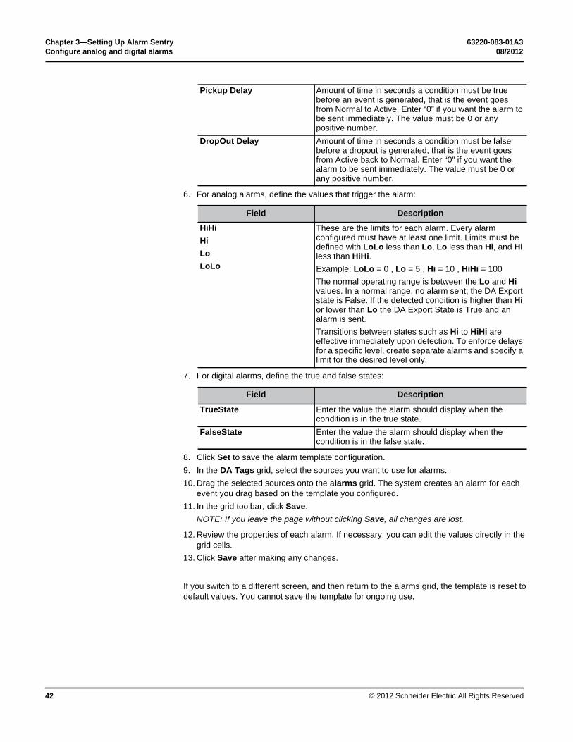
Field Description
Severity OPC severity level with which Alarm Sentry evaluates the event. Type a value between 1 and 1000. A high number means Alarm Sentry will evaluate the event to a higher alarm condition than a low number.
Pickup Delay Amount of time in seconds a condition must be true before an event is generated, that is the event goes from Normal to Active. Enter “0” if you want the alarm to be sent immediately. The value must be 0 or any positive number.

Chapter 3—Setting Up Alarm Sentry 63220-083-01A3Configure analog and digital alarms 08/2012
© 2012 Schneider Electric All Rights Reserved40
5. For analog alarms, define the values that trigger the alarm:
6. For digital alarms, enter the true and false states:
7. Click Save.
NOTE: If you leave the page without clicking Save, all changes are lost.
Define alarms for multiple DA Tags with a template
If several DA tags need similar alarms, you can define a template to set up a group of alarms at the same time. For example, you could define a template for an over current alarm and use it on multiple circuits, represented by multiple DA tags.
1. In the DA Tags grid, select the sources you want to use for alarms.2. If you have many DA tags, you can filter the grid to see the specific tags to set up.
See “Filter the grid data” on page 36 for more information about filtering the tags.
DropOut Delay Amount of time in seconds a condition must be false before a dropout is generated, that is the event goes from Active back to Normal. Enter “0” if you want the alarm to be sent immediately. The value must be 0 or any positive number.
Field Description
HiHiHiLoLoLo
These are the limits for each alarm. Every alarm configured must have at least one limit. Limits must be defined with LoLo less than Lo, Lo less than Hi, and Hi less than HiHi.Example: LoLo = 0 , Lo = 5 , Hi = 10 , HiHi = 100The normal operating range is between the Lo and Hi values. In a normal range, no alarm sent; the DA Export state is False. If the detected condition is higher than Hi or lower than Lo the DA Export State is True and an alarm is sent.Transitions between states such as Hi to HiHi are effective immediately upon detection. To enforce delays for a specific level, create separate alarms for the same source DA tag and specify a limit for the desired level only.
Field Description
TrueState Enter the value the alarm should display when the condition is in the true state. For example, “Running” can be the true state for a building generator.
FalseState Enter the value the alarm should display when the condition is in the false state. For example, “Stopped” could be the false state for a building generator.

63220-083-01A3 Chapter 3—Setting Up Alarm Sentry08/2012 Configure analog and digital alarms
© 2012 Schneider Electric All Rights Reserved 41
3. In the alarms grid, click Set Alarm Template. The Alarm Template screen appears.NOTE: If the Set Alarm Template command does not appear, expand the browser window or click the down-arrow at the end of the toolbar.
The values in the Misc1,2,3 Text boxes become drop-down options for the Alarm tag name and Condition name. The complete alarm name is composed of the values in the Alarm tag and Condition boxes.
You may include a number in any of the fields so that when you drag new sources to add alarms the number increments from the current starting point. This helps keep source names unique when adding multiple alarms.
Use at least one period in every alarm. This avoids servers where all of the Source alarms and events are shown at the root level.
For example, you can define a template with the following name format, where NN automatically increases for each alarm definition:
• Main A.Current.Under Alarm.Level StatusNN 4. In the Template Values screen, define the alarm tag and condition fields:
5. Configure the severity and delay values:
Field Description
Misc1 Text Delete the “misc1” text and enter “Main A.” Be sure to add the period at end.
Misc2 Text Delete the “misc1” text and enter “Level Status01.” Misc3 Text Delete the “misc1” text and leave the field blank.Alarm Tag Template Name First field, leave blank. Second field, select “Misc1.”
Third field, enter “Current” Uncheck the increment box.
Condition Template Name First field, enter “Under Alarm.” Second field, select “Misc2.” Third field, leave blank. Check the increment box and enter 1 as the increment value.
Field Description
Severity OPC severity level with which Alarm Sentry evaluates the event. Type a value between 1 and 1000. A high number means Alarm Sentry will evaluate the event to a higher alarm condition than a low number.
Chapter 3—Setting Up Alarm Sentry 63220-083-01A3Configure analog and digital alarms 08/2012
© 2012 Schneider Electric All Rights Reserved42
6. For analog alarms, define the values that trigger the alarm:
7. For digital alarms, define the true and false states:
8. Click Set to save the alarm template configuration. 9. In the DA Tags grid, select the sources you want to use for alarms. 10. Drag the selected sources onto the alarms grid. The system creates an alarm for each
event you drag based on the template you configured.11. In the grid toolbar, click Save.
NOTE: If you leave the page without clicking Save, all changes are lost.
12. Review the properties of each alarm. If necessary, you can edit the values directly in the grid cells.
13. Click Save after making any changes.
If you switch to a different screen, and then return to the alarms grid, the template is reset to default values. You cannot save the template for ongoing use.
Pickup Delay Amount of time in seconds a condition must be true before an event is generated, that is the event goes from Normal to Active. Enter “0” if you want the alarm to be sent immediately. The value must be 0 or any positive number.
DropOut Delay Amount of time in seconds a condition must be false before a dropout is generated, that is the event goes from Active back to Normal. Enter “0” if you want the alarm to be sent immediately. The value must be 0 or any positive number.
Field Description
HiHiHiLoLoLo
These are the limits for each alarm. Every alarm configured must have at least one limit. Limits must be defined with LoLo less than Lo, Lo less than Hi, and Hi less than HiHi.Example: LoLo = 0 , Lo = 5 , Hi = 10 , HiHi = 100The normal operating range is between the Lo and Hi values. In a normal range, no alarm sent; the DA Export state is False. If the detected condition is higher than Hi or lower than Lo the DA Export State is True and an alarm is sent.Transitions between states such as Hi to HiHi are effective immediately upon detection. To enforce delays for a specific level, create separate alarms and specify a limit for the desired level only.
Field Description
TrueState Enter the value the alarm should display when the condition is in the true state.
FalseState Enter the value the alarm should display when the condition is in the false state.

63220-083-01A3 Chapter 3—Setting Up Alarm Sentry08/2012 Configure advanced alarms
© 2012 Schneider Electric All Rights Reserved 43
Configure advanced alarms
Advanced alarms are similar to digital alarms since they can have only two states, true or false. They are configured so that the true and false state descriptions become the conditions for the alarm. However, advanced alarms are calculated based on the result of a custom expression using a script, similar to C#. The script expressions can use any number of DA values as inputs, but must always evaluate to true or false and return true or false as the result. Alarm Sentry will create an event based on the transition from true to false or from false to true.
For example, an OPC AE server is tracking two redundant power supplies. You can define an alarm to evaluate the output of each power supply. When the power supply output of one unit drops to 20% of the other unit, the alarm is triggered and Alarm Sentry sends notification.
Before you configure advanced alarms, the source OPC DA tags must be added as described above.
You can only define one advanced alarm at a time. A template function is available for advanced alarms, but you can only configure the DA tags for one alarm at a time.
Select the server with the DA Tag sources
Follow these steps to select the server which has DA Tag sources to use for setting up alarms.
1. In the Alarm Sentry toolbar, click AdvancedAlarmSetupView. The Advanced Alarms grid appears below the DA Tags grid.
2. In the DA Tags tool bar, select the server in the Server box.3. Click Apply Filter. The DA tags for the server appear in the grid.See “Filter the grid data” on page 36 for more information about filtering.

Chapter 3—Setting Up Alarm Sentry 63220-083-01A3Configure advanced alarms 08/2012
© 2012 Schneider Electric All Rights Reserved44
Create and verify the alarm expression
With advanced alarms, you manually verify an alarm definition to make sure the expression compiles and returns a True or False value.
1. In the DA Tags grid, select the sources you want to use for alarms.2. If you have many DA tags, you can filter the grid to see specific tags.3. Click on one or more DA tags and drag them to the Advanced Alarms grid. The system
creates an alarm for each DA tag and inserts default values for the alarm definition, as shown in the grid cells.
4. Edit the values in the grid cells so the alarm definition makes sense to the customer.
5. Enter the parameters for the alarm.
Field Description
Alarm Tag Delete the default value and enter a name for the alarm.Condition Template Name Delete the default value and enter the condition name.
Field Description
Severity OPC severity level with which Alarm Sentry evaluates the event. Type a value between 1 and 1000. A high number means Alarm Sentry will evaluate the event to a higher alarm condition than a low number.
Pickup Delay Amount of time in seconds a condition must be true before an event is generated, that is the event goes from Normal to Active. Enter “0” if you want the alarm to be sent immediately. The value must be 0 or any positive number.
DropOut Delay Amount of time in seconds a condition must be false before a dropout is generated, that is the event goes from Active back to Normal. Enter “0” if you want the alarm to be sent immediately. The value must be 0 or any positive number.
True State Enter the value the alarm notification should show when the condition is true.
False State Enter the value the alarm notification should show when the condition is false.

63220-083-01A3 Chapter 3—Setting Up Alarm Sentry08/2012 Configure advanced alarms
© 2012 Schneider Electric All Rights Reserved 45
6. Click in the Expression cell. The Alarm Expression editor appears in the row.
7. Type your expression in the Expression box. 8. To use an available tag in the expression, double-click on a row under Available Tags.
The tag appears in the Expression box.For example: (Int16) Source("Advosol.SimDAServer.1.SimulatedData.Ramp")
The reference consists of the C# type “(Int16)”, the rest of the reference retrieves the specific value of the source using its unique alias as defined in the DA Tags configuration.
NOTE: The editor does not allow carriage returns within the expression. If you press Enter the editor closes. Also, pasted expressions from other editors are truncated at the first carriage return.
NOTE: Do not change the alarm tag as inserted into the editor. References to the alarm tags must be in the format as added by double-clicking on the row.
9. Click Verify to make sure the expression works correctly.• If the expression compiles successfully the Verification Result box turns green. The
result “True” or “False” appears as appropriate for the expression.• If the expression does not compile, the box turns red and displays information about
the error.
10. When the expression is complete, click away from the Alarm Expression box to close the editor.
11. Click Save.NOTE: If you leave the page without clicking Save, all changes are lost.
12. Review and edit the properties of each alarm. By default, the True State and False State names are set to “True” and “False”. Edit the true and false state names as needed.
13. Click Save.

Chapter 3—Setting Up Alarm Sentry 63220-083-01A3Configure the TAG OPC DA/AE Server 08/2012
© 2012 Schneider Electric All Rights Reserved46
Configure the TAG OPC DA/AE Server
Configure DCOM for the TAG OPC DA/AE Server
The TAG OPC DA/AE Server depends on DCOM in order to operate successfully. The server should be run as a specific user with administrative permissions. Follow these steps to configure the server as a specific user.
1. In Windows, click Start > Run.2. Type “dcomcnfg.exe” and click OK. The Component Services screen appears.3. Expand the tree to Console Root > Component Services > Computers >
My Computer > DCOM Config.
4. Find the TAG OPC DA/AE Server.5. Right-click the server and select Properties.

63220-083-01A3 Chapter 3—Setting Up Alarm Sentry08/2012 Update ENM with the Alarm Sentry server
© 2012 Schneider Electric All Rights Reserved 47
6. Select the Identity tab.
7. Select This user.8. In the User box, enter or select DCOMUser. This is the user which has access to the
database, as well as local and remote DCOM permissions.9. Enter the password for the user.10. Click OK.11. Close the Component Services screen.
You can now connect to the OPC Server.
Update ENM with the Alarm Sentry server
Stop the OPC Logger and ENM services
The OPC Logger and ENM services must be stopped before you can add the Alarm Sentry server to ENM.
1. Disconnect all OPC clients from the Alarm Sentry OPC Server.2. Restart the Alarm Sentry OPC server.3. Start the ENM web application.

Chapter 3—Setting Up Alarm Sentry 63220-083-01A3Update ENM with the Alarm Sentry server 08/2012
© 2012 Schneider Electric All Rights Reserved48
4. On the Setup screen, click System > Preferences. The Preferences page appears.
5. Click the stop icon for both services. A confirmation message appears. 6. Click OK. A popup message appears to indicate the service status. 7. Click OK.8. While both services are stopped, open the Windows Task Manger.9. On the Processes tab, verify that the DanSrvAE.exe process does not appear in the list.
Configure the OPC Server in Event Notification Module
Add the PL TAG OPC AE.1 server to the list of servers for ENM.
1. Start the ENM web application.2. Click Setup in the toolbar.

63220-083-01A3 Chapter 3—Setting Up Alarm Sentry08/2012 Update ENM with the Alarm Sentry server
© 2012 Schneider Electric All Rights Reserved 49
3. On the Setup page, click OPC Server > Edit. The OPC Server Configuration screen appears.
4. Click Auto-detect OPC Servers. The PL TAG OPC AE.1 server should appear in the Available Servers box.
5. Select the PL TAG OPC AE.1 server and click > to move it to the Selected Servers box.6. Click Apply Changes to save your changes and update the events in the ENM system.
NOTE: If you make changes to the Alarm Sentry configuration, you must repeat this procedure for those changes to take effect in ENM.
Restart the OPC Logger and ENM services
The OPC Logger and ENM services must be restarted after you add the Alarm Sentry server to ENM.
1. Disconnect all OPC clients from the Alarm Sentry OPC Server.2. Restart the Alarm Sentry OPC server.3. Start the ENM web application.4. On the Setup screen, click System > Preferences. The Preferences page appears.5. Click the start button for both services. A confirmation message appears.6. Click OK. A popup message appears to indicate the service status.7. Click OK.

Chapter 3—Setting Up Alarm Sentry 63220-083-01A3Update ENM with the Alarm Sentry server 08/2012
© 2012 Schneider Electric All Rights Reserved50

63220-083-01A3 08/2012
© 2012 Schneider Electric All Rights Reserved 51
Chapter 4 — Event Notification Module Control
The Maintenance Mode Control page provides a way to change the status of maintenance mode groups. After you enable a maintenance mode group, all alarms and events originating from nodes in the group will not be sent to recipients.
NOTE: If you want the alarms to be sent again from the group, you must disable maintenance mode.
You must be a member of either ENMAdmin or ENMControl to access and change the maintenance mode status. See Chapter 2—Setting up Event Notification Module for instructions to add ENM users.
Change the status of maintenance mode groups
Follow these steps to enable or disable a maintenance mode group. If enabled, the alarms and events originating from nodes in the group will not be sent to recipients.
1. On the Home page, click Control > Maintenance Mode Status. The Maintenance Mode Control page appears. This page displays all the maintenance groups set up in ENM.
2. Find the maintenance group you want to change. If the list is very long, you can filter the list by entering the group name in the Filter by box. • Under Enabled, a check mark in the box indicates the maintenance group is active.
The nodes in an active maintenance group do not send alarm and event messages.

Chapter 4—Event Notification Module Control 63220-083-01A3Change the status of maintenance mode groups 08/2012
© 2012 Schneider Electric All Rights Reserved52
• A blank box indicates the group is not active. The nodes in an inactive group send alarm and event messages.
3. To change the status, click the check box for the group. The Enter reason for status change row appears.
4. Type the reason for changing the status and click Continue.ENM sends this text as a message to the recipients who are subscribed to the affected nodes.

63220-083-01A3 08/2012
© 2012 Schneider Electric All Rights Reserved 53
Chapter 5 — Event Notification Module Monitoring
The Monitoring Events pages display live and historical viewing of alarms and events received from the OPC alarm and event servers. You can also set options to display or hide certain alarm and event attributes.
View live monitoring data
In ENM, you can view current monitoring information as it happens.
• In the menu bar, click Monitoring > Live. The Monitoring Events page appears.
ENM refreshes this page every 5 seconds. You can click a column heading to sort the grid data.

Chapter 5—Event Notification Module Monitoring 63220-083-01A3View historical monitoring data 08/2012
© 2012 Schneider Electric All Rights Reserved54
View historical monitoring data
You can view historical monitoring data with filtering and sorting. You can export the grid data to a Microsoft Excel spreadsheet.
• On the home page, click Monitoring > Historical. The Monitoring Events page appears.
Use basic filtering
Filter the data as follows:
1. Under Date Time Filter, change the Start Date/Time and End Date/Time to see events within a specific date and time range.
2. Under Filter Type, select Auto. In any column header, click the filter icon and select a filter option.
The events matching the filter criteria appear in the grid.

63220-083-01A3 Chapter 5—Event Notification Module Monitoring08/2012 View historical monitoring data
© 2012 Schneider Electric All Rights Reserved 55
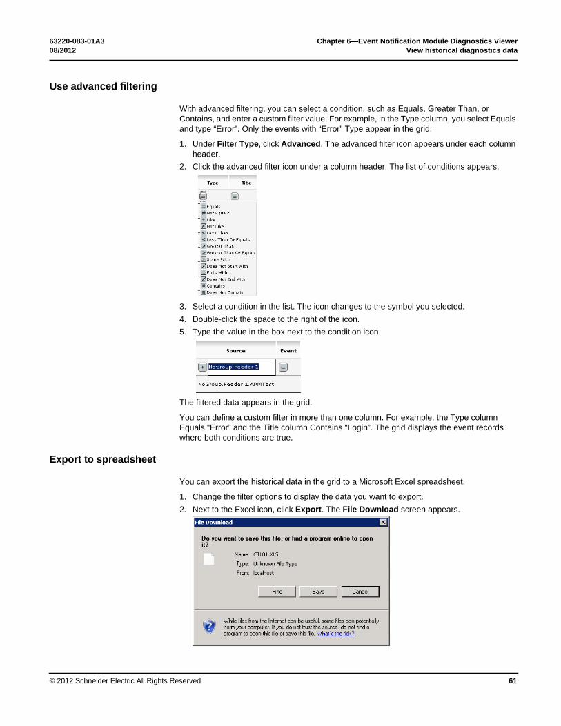
Use advanced filtering
With advanced filtering, you can select a condition, such as Equals, Greater Than, or Contains, and enter a custom filter value. For example, in the Type column, you select Equals and type “Error”. Only the events with “Error” Type appear in the grid.
1. Under Filter Type, click Advanced. The filter icon appears under each column header.2. Click the filter icon under a column header. The list of conditions appears.
3. Select a condition in the list. The button changes to the symbol you selected.4. Double-click the space to the right of the button.5. Type the value in the box next to the condition button.
The filtered data appears in the grid.
You can define a custom filter in more than one column. For example, Type column Equals “Error” and Title column Contains “Login”. The grid displays the event records where both conditions are true.

Chapter 5—Event Notification Module Monitoring 63220-083-01A3Export to spreadsheet 08/2012
© 2012 Schneider Electric All Rights Reserved56
Export to spreadsheet
You can export the historical data in the grid to a Microsoft Excel spreadsheet.
1. Change the filter options to display the data you want to export.2. Next to the the Excel icon, click Export. The File Download screen appears.
3. Do either of the following:• Click Find to select Microsoft Excel to view the spreadsheet.• Click Save to save the file to a disk drive.

63220-083-01A3 Chapter 5—Event Notification Module Monitoring08/2012 Configure monitoring options
© 2012 Schneider Electric All Rights Reserved 57
Configure monitoring options
You can select the columns to display and define the number of data rows to display on each page.
1. In the menu bar, click Monitoring > Options. The Monitoring Options page appears.
2. Select the column titles you want to see in the data grid.3. In Rows Per Page, select the number of rows.The changes are saved automatically when you click another menu in the toolbar.

Chapter 5—Event Notification Module Monitoring 63220-083-01A3Configure monitoring options 08/2012
© 2012 Schneider Electric All Rights Reserved58

63220-083-01A3 08/2012
© 2012 Schneider Electric All Rights Reserved 59
Chapter 6 — Event Notification Module Diagnostics Viewer
View live diagnostics data
The Diagnostics page provides real time and historical viewing of activity relating to the Event Notification Module (ENM). It does not provide information on events transmitted from OPC alarm and event servers.
In ENM, you can view current diagnostic information as it happens.
• In the menu bar, click Diagnostics > Live. The Diagnostic Events page appears.
ENM refreshes this page every 5 seconds. You can click a column heading to sort the grid data.

Chapter 6—Event Notification Module Diagnostics Viewer 63220-083-01A3View historical diagnostics data 08/2012
© 2012 Schneider Electric All Rights Reserved60
View historical diagnostics data
You can view historical diagnostic data with filtering and sorting. You can export the grid data to a Microsoft Excel spreadsheet.
• On the home page, click Diagnostics > Historical. The Diagnostic Events page appears.
Use basic filtering
Filter the historical diagnostics data as follows:
1. Under Date Time Filter, change the Start Date Time and End Date Time to see events within a specific date and time range.
2. Under Filter Type, select Auto.3. In any column header, click the filter icon and select a filter option.
The events matching the column filter criteria appear in the grid.
63220-083-01A3 Chapter 6—Event Notification Module Diagnostics Viewer08/2012 View historical diagnostics data
© 2012 Schneider Electric All Rights Reserved 61
Use advanced filtering
With advanced filtering, you can select a condition, such as Equals, Greater Than, or Contains, and enter a custom filter value. For example, in the Type column, you select Equals and type “Error”. Only the events with “Error” Type appear in the grid.
1. Under Filter Type, click Advanced. The advanced filter icon appears under each column header.
2. Click the advanced filter icon under a column header. The list of conditions appears.
3. Select a condition in the list. The icon changes to the symbol you selected. 4. Double-click the space to the right of the icon. 5. Type the value in the box next to the condition icon.
The filtered data appears in the grid.
You can define a custom filter in more than one column. For example, the Type column Equals “Error” and the Title column Contains “Login”. The grid displays the event records where both conditions are true.
Export to spreadsheet
You can export the historical data in the grid to a Microsoft Excel spreadsheet.
1. Change the filter options to display the data you want to export. 2. Next to the Excel icon, click Export. The File Download screen appears.

Chapter 6—Event Notification Module Diagnostics Viewer 63220-083-01A3Configure diagnostic options 08/2012
© 2012 Schneider Electric All Rights Reserved62
3. Do either of the following:• Click Find to select Microsoft Excel to view the spreadsheet.• Click Save to save the file to a disk drive.
Configure diagnostic options
You can select the columns to display and define the number of data rows to display on each page.
1. On the home page, click Diagnostics > Options. The Diagnostic Options page appears.
2. Select the column titles you want to see in the data grid.3. In Rows Per Page, select the number of rows.
The changes are saved automatically when you click another menu in the toolbar.

63220-083-01A3 08/2012
© 2012 Schneider Electric All Rights Reserved 63
Chapter 7 — Resolve Issues
If symptoms exist and do not match with the ones listed in this appendix, or if the attempt to implement the prescribed solution does not resolve the issue, please contact Technical Support at 615-287-3400.
Problems and Resolutions
Problem Resolution
ENM service and the OPCAELogger Service do not start after installing ENM.
After installing ENM, you must restart the server. The ENM service and the OPCAELogger Service will start automatically after the system restarts.
The OPC AE Server and ENM application are on separate machines, and you are having problem connecting to the OPC server.
The configuration of the DCOM settings for the two machines must be corrected. Contact Technical Support.
ENM installation restarts after adding a new user.
If a new Windows user profile is created after installing ENM, then logging into the machine as the new user will cause the ENM install to restart. To avoid this issue, create additional local Windows user profiles before installing ENM.
“The page cannot be displayed” message appears when accessing the ENM web application.
ENM relies on integrated Windows authentication for security. If the IIS setting HTTP Keep-Alives Enabled is unchecked for the default website integrated Windows authentication does not work and the resulting error message is shown.To correct the issue, go to the Default Web Site Properties screen, select the Web Site tab and check the HTTP Keep-Alives Enabled option.
Blank screen appears after you click the AE Subscription menu link on the Setup page.
When this happens, click on the AE Subscription menu link again.

Chapter 7—Resolve Issues 63220-083-01A3Problems and Resolutions 08/2012
© 2012 Schneider Electric All Rights Reserved64
Problem Resolution
The names of some filters migrated from version 5.x are truncated in ENM filter drop-down boxes.
The filter drop-down boxes in ENM are limited to 40 characters, including spaces. During migration from version 5.x, 5 characters are appended to the name of the filter. If the original filter name is longer than 35 characters, then the filter name is truncated in ENM.
The user interface looks skewed or out of proportion.
The minimum recommended screen size for ENM is 1024 by 768. Use the Windows Monitor Properties page to change the screen size. Otherwise, maximize the browser window and refresh the page.
Configuration changes do not take effect in the application.
After you change the configuration settings, restart the ENM service and the PLOpcAELogger service. To restart the services, use System > Preferences page in ENM or the Windows Service Controller in the Control Panel.
In Alarm Sentry, the DA Tag selection page is unable to browse the DA Tags.
Open Computer Management and verify the PL AlarmGen Host Service is started.The PL AlarmGen Host Service allows the web configuration tool to access the various OPC DA servers and provides the DA tags available on these servers. In order for the configuration tool to function correctly the Host Service must be running and accessible to the IIS server running the configuration application.
If the PL Alarm Gen Host Service is started and the problem continues, check the firewall configuration, as follows:The Host Service provides web services which are available on two network ports: 7897 and 7896. These ports must be opened on any firewall which is installed on the server. The Alarm Sentry install process opens these ports as well as port 81 for use by the eSolutions website. If disabling the firewall corrects the issue, open ports 7897 and 7896 before enabling the firewall.To facilitate opening the correct ports, the following batch files are included in the install:1. EnablePorts_PLES.bat opens the ports for all networks.2. EnablePorts_PLES.bat opens the port for the subnet only.3. DisablePorts_PLES.bat closes the ports.
The folder is:C:\Program Files\Schneider Electric\EventNotificationModule\PLeSolutionsWeb\ AlarmGenUI\Services

63220-083-01A3 08/2012
© 2012 Schneider Electric All Rights Reserved 65
Chapter 8 — Relay Attribute Definitions
Definitions
Attributes
Relay Attributes for “Dial-up TAP”:
Term Description
GSM Global System for Mobile communications. This is a communications standard used by many mobile phones. SMS is defined in the GSM standard, allowing messages of up to 160 characters.
OTA Over-the-Air activation system. his is a category of the type of device that is connecting to the SMSC – used in the SMPP standard.
PL SMS PowerLogic System Manager Software. SIM card Subscriber Identity Module. This is a chip that is placed into a
mobile phone and securely stores the service-subscriber key of a user, allowing the user to switch phones by replacing the SIM card. This card is mandatory in all devices that communicate using GSM.
SMPP Short Message Peer to Peer. This is an open standard that sends and SMS by connecting directly to an SMSC. Often used to submit messages in bulk.
SMS Short Message Service. This is a communications protocol that allows the exchange of short text messages (160 7-bit characters, including spaces) between mobile phones. More information about SMS, including other protocols can be found at the website www.smsforum.net.
SMSC Short Message Service Centre. Routes an SMS sent by a user, to the specified destination.
SNPP Simple Network Paging Protocol. This is a standard protocol for sending messages to SMS and paging devices.
TAP Telocator Alphanumeric Protocol. This protocol can be used to send SMS messages using a standard modem and telephone landline.
UCP Universal Computer Protocol. This is a protocol that is used by mobile phones to connect to an SMSC.
VMS Voice Mail System. This is a category of the type of device that is connecting to the SMSC – used in the SMPP standard.
Attribute Description
Dialup Device Name of the device for sending ENM messages.Dialup Speed The baud rate of the communication system.

Chapter 8—Relay Attribute Definitions 63220-083-01A3Attributes 08/2012
© 2012 Schneider Electric All Rights Reserved66
Relay Attributes for “Email”:
Data Format The data bits / parity / stop bits. Contact your provider to get this. See the ActiveXperts website for more information:http://www.activexperts.com/xmstoolkit/smsclist/
Protocol Type of provider, either TAP or UCP. Password The provider password, if required.Sender Number The reply-to number in the SMS.Recipient Number SMS number of the recipient.Provider Dial String The number to dial for provider access.Prefix Text Text to append before the message body of the SMS.Postfix Text Text to append after the message body of the SMS.Retries The number of unsuccessful send attempts before canceling
the SMS.Log File Path The full path, including the file name, of the log file. All device
commands and responses are written to this file.Message Defines the message sent out to the recipient. The default
value is [MESSAGE] which will cause the notification to include the OPC Message text. This value can be customized as described in “Define messages for relay notifications (optional)” on page 29.
Attribute Description
“From” Appears in the “From” field of the sent email.“To” Addresses of e-mail recipients, comma separated.SMTP Server Host This can be a server name or an IP address of the provider.
Usually obtained from the IT department.Credential User Name Login for SMTP Server, if required.Credential Password Password for SMTP Server, if required.Retries This number determines how many unsuccessful send
attempts are made before the email is aborted.Prefix Text Text to append before the subject of the email.Postfix Text Text to append after the subject of the email.Enable SSL True or False – indicates whether the email is sent using
Secure Sockets.Subject The text that will appear in the subject line of the sent email.Pickup Directory Location Path to the folder where email messages are to be placed in
order to be processed by the SMTP server. Blank by default. Delivery Method Indicates how email messages are delivered. Blank by
default. Options include:• An SMTP server.• Moving the email into the pickup directory for IIS, which
then delivers the message.• Moving the email to a directory specified by
PickupDirectoryLocation for later delivery by another application.
SMTP Service Port An integer that represents the port number on the SMTP host. The default value is 25.

63220-083-01A3 Chapter 8—Relay Attribute Definitions08/2012 Attributes
© 2012 Schneider Electric All Rights Reserved 67
Relay Attributes for “GSMOUT”:
Relay Attributes for “SMPP”:
SMTP Timeout An integer that specifies the time-out value in seconds. The default value is 60 seconds.
Message Defines the message sent out to the recipient. The default value is [MESSAGE] which will cause the notification to include the OPC Message text. This value can be customized as descried Chapter 3.
Attribute Description
Gsm Device Name of the device to use for sending SMS messages.Gsm Sim Pin Required if SIM card is pin-protected.Gsm Prefix Text Text to append before the subject of the SMS.Gsm Postfix Text Text to append after the subject of the SMS.Gsm Retries This number determines how many unsuccessful send
attempts are made before the SMS is aborted.Gsm Recipient SMS number of the recipient.Log File Path This is the full path (including name) of the log file. All device
commands and responses are written to this file.Message Defines the message sent out to the recipient. The default
value is [MESSAGE] which will cause the notification to include the OPC Message text. This value can be customized as descried Chapter 3.
Attribute Description
Smpp Server This can be a server name or an IP address of the provider.Smpp Server Port TCP port used for connection to SMPP provider.Smpp System ID Account used to login to the SMSC provider’s system.Smpp Password Password used to login to the SMSC provider’s system.Smpp System Type Type of SMSC provider, such as SMPP, VMS, or OTA.Smpp Keep Alive (Seconds) Integer representing the number of seconds to keep a
communication channel open.Smpp Timeout (Milliseconds) Integer representing the server timeout in milliseconds –
used for all network operations such as Connect or Send.Smpp Prefix Text Text to append before the subject of the SMS.Smpp Postfix Text Text to append after the subject of the SMS.Smpp Retries This number determines how many unsuccessful send
attempts are made before the SMS is aborted.Smpp Recipient SMS number of the recipient.Log File This is the full path (including name) of the log file. All device
commands and responses are written to this file.Message Defines the message sent out to the recipient. The default
value is [MESSAGE] which will cause the notification to include the OPC Message text. This value can be customized as descried Chapter 3.

Chapter 8—Relay Attribute Definitions 63220-083-01A3Attributes 08/2012
© 2012 Schneider Electric All Rights Reserved68
Relay Attributes for “SNMP”:
Relay Attributes for “SNPP”:
Relay Attributes for “MODBUS”:
Attribute Description
Snmp Server This can be a server name or an IP address of the provider. Required for the relay to work
Snmp Community This name is used to identify the group of the agentSnmp Port An integer that represents the port number on the SNMP
host and the client. The default value is 162.Snmp Protocol Version This option is not editable and only SNMP v2c is selectedMessage Defines the message sent out to the recipient. The default
value is [MESSAGE] which will cause the notification to include the OPC Message text. This value can be customized as descried Chapter 3.
Attribute Description
Snpp Server This can be a server name or an IP address of the provider.Snpp Server Port TCP port used for connection to SMPP provider.Snpp Password Password used to login to the SMSC provider’s system.Snpp Timeout (Milliseconds) Integer representing the server timeout in milliseconds –
used for all network operations such as Connect or Send.Snpp Prefix Text Text to append before the subject of the SMS.Snpp Postfix Text Text to append after the subject of the SMS.Snpp Retries This number determines how many unsuccessful send
attempts are made before the SMS is aborted.Snpp Recipient SMS number of the recipient.Log File This is the full path (including name) of the log file. All device
commands and responses are written to this file.Message Defines the message sent out to the recipient. The default
value is [MESSAGE] which will cause the notification to include the OPC Message text. This value can be customized as descried Chapter 3.
Attribute Description
IP Address This is the IP address of the deviceDevice ID The Modbus/device ID of the deviceRegister Number Register number to which a value is writtenSwitch ON Value ON Value to be written to the registerSwitch OFF Value OFF Value to be written to the registerTime Duration for OFF (Seconds)
Time period for the ON value of the register number to be swapped by the OFF number

63220-083-01A3 08/2012
© 2012 Schneider Electric All Rights Reserved 69
Chapter 9 — OPC AE Server for PLSCADA
If you are connecting a PowerLogic SCADA OPC Server to Event Notification Module, read this appendix. The PowerLogic SCADA OPC server connects to the PowerLogic SCADA server and acts as an OPC-compliant Alarm and Event server.
Installation
The ENM DVD allows for the installation of the PLSCADA OPC Server application. The installer package installs the PLSCADA OPC server if PowerLogic SCADA 7.1 is present on the machine.
Citect Configuration
The OPC server connects to the installed PowerLogic SCADA server to retrieve events. The translation of PLSCADA alarms into OPC events is as follows.
Event Tree
The OPC tree structure is built from the Alarm Tag using a UNC type structure. Each level of the tree is defined by a back slash “\” character so that multilevel trees can be defined. For example:
Source\Event1
Source\Event2
produces a tree with “Source” as the root and “Event1” and “Event2” as sub-levels:
Source
Event1
Event2
Trees can have as many levels as needed to represent the event structure the customer desires.
PowerLogic SCADA Event Priorities
PLSCADA priorities are defined in the Alarm Category Screen. A priority is an integer value between 1 and 255. The value 1 is the considered the highest priority while 255 is the lowest.
PLSCADA OPC server converts these priority values into values consistent with the OPC scale where 1 is lowest and 1000 is highest. A PLSCADA priority of 1 is equivalent to OPC severity of 1000. A PLSCADA priority of 255 is equivalent to OPC severity of 1.

Chapter 9—OPC AE Server for PLSCADA 63220-083-01A3Citect Configuration 08/2012
© 2012 Schneider Electric All Rights Reserved70

63220-083-01A3 08/2012
© 2012 Schneider Electric All Rights Reserved 71
Chapter 10 — Database Maintenance Utility
SQL Scripts and Windows Tasks
The Database Maintenance Utility is a set of SQL scripts scheduled to run daily as a Windows scheduled task. These scripts and tasks facilitate the maintenance of the various databases associated with Event Notification Module (ENM). They are installed during the ENM installation.
The scripts associated with the database maintenance tasks are located in the DBMaintenance directory. To change the directory for the backup or some other aspect of the maintenance tasks, edit the scripts in the subdirectory associated with the particular task.
All tasks associated with the Database maintenance are scheduled to run once per day during the early morning hours.
Task Description
Database Backup Performs backup on the databases.Log Backup Performs a backup of the log files.Rebuild Index Rebuilds the table indexes.Reorg Index Reorganizes the table indexes.ShrinkTranLog Shrinks the transaction log.TrimDiagnosticLogTable Removes old diagnostic events. By default this task leaves
5000 records for diagnostic events. Usually, this number is sufficient for monitoring the health of the system. If you wish to leave more events in the table you may edit the TrimDiagnosticLogTable.sql file. You should not increase the value to more than 50,0000. If you do, the database may grow larger than the 4 GB limit.
TrimEventsTable Removes old monitoring events. By default this leaves 1,000,000 records in the table. If you wish to leave more records or do not wish to trim the events table, edit the TrimEventsTable.sql file or disable the scheduled task.

Chapter 10—Database Maintenance Utility 63220-083-01A3SQL Scripts and Windows Tasks 08/2012
© 2012 Schneider Electric All Rights Reserved72

63220-083-01A3 08/2012
© 2012 Schneider Electric All Rights Reserved 73
Chapter 11 — Hot Standby Configuration
In hot-standby mode, two separate installations of ENM are required on two PLSCADA servers, configured to run as redundant servers. Only one ENM server will be active at any instance, although both installations will record the alarms from PLSCADA. If the primary server becomes unavailable, the second ENM server will take over active paging responsibilities. All alarms received by the second ENM server, while the primary server is unavailable, will be synchronized as soon as the primary server comes back online.
The following sections describe how to configure the ENM and PLSCADA servers to enable hot-standby mode.
Prerequisites
Complete these steps before you configure ENM to run in “Hot-Standby” mode:
1. Install ENM 7.0 or higher on both servers. Refer to Event Notification Installation Guide for instructions.
2. Configure all alarm tags in PLSCADA. Refer to PLSCADA documentation for instructions to use PLSCADA software.
Configure ENM on the Primary Server
1. On the primary server, configure ENM as described in the previous chapters:• Servers• Filters• Relays and recipients• Scheduling• Subscriptions
2. Test and verify that the configurations are correct.

Chapter 11—Hot Standby Configuration 63220-083-01A3Configure ENM on the Primary Server 08/2012
© 2012 Schneider Electric All Rights Reserved74
3. Start the HotStandby configuration tool: In Windows, go to Start > Program Files > Schneider Electric > Event Notification Module > Hot Standby > Hot Standby Config UI. The following screen appears.
4. Check the Enable Hot Standby option.5. Enter the Primary Server and the Secondary Server name or IP address.6. Click Apply Changes.7. Click the Export/Import Settings tab.
8. In the Export File Name box, enter a local folder and file name to export the settings and click Export Settings.
NOTE: Do not export the file to a network drive.

63220-083-01A3 Chapter 11—Hot Standby Configuration08/2012 Configure ENM on the Secondary Server
© 2012 Schneider Electric All Rights Reserved 75
Configure ENM on the Secondary Server
1. Copy the Sag04_ENM_Setup.zip or the file which you exported to the local drive from the remote server.
2. Close the ENM web application if it is open.3. Stop the ENM and OPC Logger services using the Windows Control Panel.4. Start the Hot Standby Configuration tool.5. Click the Export/Import Settings tab.6. Select the file in the Import File Name box and click Import Settings.
NOTE: During the import, the Diagnostic Log tab is automatically displayed and all progress is shown here. Check if there are any errors indicated here. Most errors encountered will be SQL time out errors or SQL access errors. If you do encounter any errors, restart the SQL server and import the settings again.
7. Click the HotStandby Configuration tab and click Apply Changes.8. After successfully importing the settings, start the ENM, OPC Logger and PLHotStandby
Services using the Windows Control Panel.

Chapter 11—Hot Standby Configuration 63220-083-01A3Configure PLSCADA Servers for Hot-Standby Operation 08/2012
© 2012 Schneider Electric All Rights Reserved76
Configure PLSCADA Servers for Hot-Standby Operation
Share server folders
1. Share the Folder “PowerLogic SCADA 7.20” on both the servers: Primary and Secondary.If PLSCADA was installed in the default location, the folder is located at:
C:\Documents and Settings\All Users\Application Data\Schneider Electric\PowerLogic SCADA 7.20
2. On the primary server, map the “PowerLogic SCADA 7.20” folder from the secondary as network drive “G”. You can use a different letter if G is already taken.
3. On the secondary server, map the “PowerLogic SCADA 7.20” folder from the primary as drive G, if it is available. Use the same drive letter as you selected in step 2.

63220-083-01A3 Chapter 11—Hot Standby Configuration08/2012 Configure PLSCADA Servers for Hot-Standby Operation
© 2012 Schneider Electric All Rights Reserved 77
Configure Citect Software
Complete the following steps on the primary server and the secondary server.
1. Start the Citect Project Editor and open the Citect Computer Setup Wizard.2. Check the Custom Setup option and click Next.
3. Make sure the correct project is selected and click Next.
4. Check the Server and Control Client option.

Chapter 11—Hot Standby Configuration 63220-083-01A3Configure PLSCADA Servers for Hot-Standby Operation 08/2012
© 2012 Schneider Electric All Rights Reserved78
5. You can also check the Multi-Process option if appropriate for the server setup.
6. Select the TCP/IP option.

63220-083-01A3 Chapter 11—Hot Standby Configuration08/2012 Configure PLSCADA Servers for Hot-Standby Operation
© 2012 Schneider Electric All Rights Reserved 79
7. Depending on the server setting, check the Internet Server option or leave this in the default setting.
8. On the Alarm Server Properties Setup screen, set the Primary Alarms Server save path to C:\ProgramData\Schneider Electric\PowerLogic SCADA 7.20\Alarm.
9. Set the Standby Alarms Server save path to “<network drive>\Alarm” such as: “G:\Alarm”.
10. Other options can remain in the default values.NOTE: If the Alarm folder is not already present in that directory the computer setup wizard is going to create one when the program is run.
11. Check the Inhibit triggered trends on startup option, if appropriate for the server setup.12. Click Next until the Security Setup – Control Menu screen appears.

Chapter 11—Hot Standby Configuration 63220-083-01A3Configure PLSCADA Servers for Hot-Standby Operation 08/2012
© 2012 Schneider Electric All Rights Reserved80
13. Check the Kernel on menu option.
14. Click Next until the wizard completes. You can change default values, if necessary.15. On the final wizard screen, click Finish. Citect will compile the project.
If the Alarms folder is not present in the “PowerLogic SCADA 7.20” folder, a message appears to confirm that you want to create a new folder in that directory.
Click OK to continue.
Repeat these steps on the secondary server.

63220-083-01A3 Chapter 11—Hot Standby Configuration08/2012 Troubleshooting Citect Setup
© 2012 Schneider Electric All Rights Reserved 81
Troubleshooting Citect Setup
Citect INI file settings
When you try to connect ENM with Citect, Make sure these changes are made in the “Computer Setup Editor” under Citect Project Editor:
CtAPI
AllowLegacyConnections = 1
AllowLegacyServices = 1
LAN
AllowLegacyConnections = 1
Citect-Regkey entry
Verify the following registry key exist or can run the Citect-Regkey entry from the CD:
[HKEY_LOCAL_MACHINE\SOFTWARE\Citect\SCADA Installs] "ActiveINIPath"="C:\\Documents and Settings\\All Users\\Application Data\\Schneider Electric\\PowerLogic SCADA 7.10\\Config\\"
[HKEY_LOCAL_MACHINE\SOFTWARE\Citect\SCADA Installs\7.10] [HKEY_LOCAL_MACHINE\SOFTWARE\Citect\SCADA Installs\7.10\PowerLogic SCADA]
"DefaultINIPath"="C:\\Documents and Settings\\All Users\\Application Data\\Schneider
Electric\\PowerLogic SCADA 7.10\\Config\\citect.ini"
@="Citect"
Server switching delays
If the switching of the servers is delayed by a couple of minutes or more, a change is required. Refer to Faster Alarm Redundancy Switchover.

Chapter 11—Hot Standby Configuration 63220-083-01A3Troubleshooting Citect Setup 08/2012
© 2012 Schneider Electric All Rights Reserved82

Electrical equipment should be installed, operated, serviced, and maintained only by qualified personnel. No responsibility is assumed by Schneider Electric for any consequences arising out of the use of this material.
63220-083-01A3 08/2012Replaces 3080IB0801 dated 01/2010 and 63220-083-01A2 dated 05/2012© Schneider Electric All Rights Reserved.
Schneider Electric295 Tech Park Drive, Suite 100LaVergne, TN 37086 USA
For technical support:[email protected](00) + 1 250 544 3010
Contact your local Schneider Electric sales representative for assistance or go towww.schneider-electric.com
Event Notification Module 7.0
User Guide