event management guide - ibm · describes how the event gateway performs event enrichment, and how...
TRANSCRIPT
Network Manager IP EditionVersion 4 Release 1
Event Management Guide
R4.1 E1
���

Network Manager IP EditionVersion 4 Release 1
Event Management Guide
R4.1 E1
���

NoteBefore using this information and the product it supports, read the information in“Notices” on page 235.
This edition applies to version 4.1 of IBM Tivoli Network Manager IP Edition (product number 5724-S45) and to allsubsequent releases and modifications until otherwise indicated in new editions.
© Copyright IBM Corporation 2006, 2013.US Government Users Restricted Rights – Use, duplication or disclosure restricted by GSA ADP Schedule Contractwith IBM Corp.

Contents
About this publication . . . . . . . . vIntended audience . . . . . . . . . . . . vWhat this publication contains . . . . . . . . vPublications . . . . . . . . . . . . . . viiAccessibility . . . . . . . . . . . . . . xTivoli technical training. . . . . . . . . . . xSupport and community information . . . . . . xiConventions used in this publication . . . . . . xii
Chapter 1. About polling the network . . 1Poll policies . . . . . . . . . . . . . . 2
Poll policy parameters . . . . . . . . . . 2Poll policy scope . . . . . . . . . . . . 2
Poll definitions . . . . . . . . . . . . . 4Poll definition parameters . . . . . . . . . 4Polling mechanisms . . . . . . . . . . . 5Poll definition types . . . . . . . . . . . 8Data labels . . . . . . . . . . . . . . 9Ping polling properties and metrics . . . . . 10
Multibyte data in poll definitions . . . . . . . 10
Chapter 2. Enabling and disabling polls 11
Chapter 3. Creating polls . . . . . . . 13Creating fully featured poll policies . . . . . . 13Creating simple poll policies. . . . . . . . . 19
Chapter 4. Creating new poll definitions 21Creating basic threshold poll definitions . . . . . 21Creating generic threshold poll definitions . . . . 23Creating chassis and interface ping poll definitions 25Creating remote ping and link state poll definitions 27
Chapter 5. Changing polls . . . . . . 29Changing poll policies . . . . . . . . . . . 29
Example poll policy . . . . . . . . . . 32Changing poll definitions. . . . . . . . . . 34
Changing basic threshold poll definitions . . . 34Changing generic threshold poll definitions . . 36Changing chassis and interface ping polldefinitions . . . . . . . . . . . . . . 38Changing remote ping and link state polldefinitions . . . . . . . . . . . . . . 40Example customized poll definition . . . . . 41Example basic threshold expression . . . . . 42Example generic threshold expression . . . . 43
Chapter 6. Deleting poll policies . . . . 45
Chapter 7. Deleting poll definitions . . 47
Chapter 8. Managing adaptive polling 49Adaptive polling scenarios . . . . . . . . . 49
Rapid confirmation that device is really down . . 49Rapid confirmation of a threshold violation. . . 52
Creating adaptive polls . . . . . . . . . . 55
Chapter 9. Administering networkpolling . . . . . . . . . . . . . . . 57Administering polls . . . . . . . . . . . 57
Retrieving poll status . . . . . . . . . . 57Enabling and disabling polls. . . . . . . . 57Refreshing polls . . . . . . . . . . . . 58Copying polls across domains . . . . . . . 58Polling suspension options . . . . . . . . 59Administering poll policy throttling . . . . . 60Speeding up ncp_poller startup by not checkingSNMP credentials . . . . . . . . . . . 61Configuring Link State polling . . . . . . . 61
Administering multiple pollers . . . . . . . . 61Multiple poller overview . . . . . . . . . 62Setting up an additional poller . . . . . . . 62Removing a poller . . . . . . . . . . . 64
Administering historical polling . . . . . . . 65Configuring how much historical performancedata is stored . . . . . . . . . . . . . 65Deleting historical polling data . . . . . . . 66Configuring storage of Ping response times. . . 66
Chapter 10. Troubleshooting pingpolling of the network . . . . . . . . 69
Chapter 11. About event enrichmentand correlation . . . . . . . . . . . 71Event enrichment . . . . . . . . . . . . 71
Quick reference for event enrichment . . . . . 71Event filtering . . . . . . . . . . . . 73Event states . . . . . . . . . . . . . 80Event handling . . . . . . . . . . . . 84Example: Default enrichment of a TivoliNetcool/OMNIbus trap event . . . . . . . 103
Event Gateway plugins . . . . . . . . . . 106Plugin descriptions . . . . . . . . . . 106Plug-in subscriptions . . . . . . . . . . 114
Root-cause analysis . . . . . . . . . . . 117Quick reference for RCA. . . . . . . . . 118Precedence value . . . . . . . . . . . 118Poller entity . . . . . . . . . . . . . 120RCA and unmanaged status . . . . . . . 122RCA stitchers . . . . . . . . . . . . 123Examples of root cause analysis . . . . . . 127
Chapter 12. Configuring eventenrichment . . . . . . . . . . . . 139Configuring extra event enrichment . . . . . . 139
Modifications to the ObjectServer alerts.statustable . . . . . . . . . . . . . . . 139
© Copyright IBM Corp. 2006, 2013 iii
Example: Enriching an event with main nodedevice location . . . . . . . . . . . . 140Example: Enriching an event with interfacename . . . . . . . . . . . . . . . 141
Configuring the ObjectServer update interval field 143Using the OQL service provider to log into theEvent Gateway databases . . . . . . . . . 144
Querying the ObjectServer . . . . . . . . 144Querying the NCIM database . . . . . . . 144
Resynchronizing events with the ObjectServer . . 145
Chapter 13. Configuring EventGateway plug-ins. . . . . . . . . . 147Enabling and disabling plugins . . . . . . . 147Listing plug-in information . . . . . . . . . 148Modifying event map subscriptions . . . . . . 149Setting plug-in configuration parameters . . . . 151Configuring the SAE plug-in . . . . . . . . 152
Configuring summary field information inservice-affected events . . . . . . . . . 152Adding SAE types to the SAE plug-in . . . . 153
Chapter 14. Configuring root-causeanalysis. . . . . . . . . . . . . . 155Configuring the poller entity . . . . . . . . 155Configuring the maximum age difference forevents . . . . . . . . . . . . . . . . 156
Appendix A. Default poll policies . . . 159Default ping policies . . . . . . . . . . . 159Default remote ping policies . . . . . . . . 159Default SNMP threshold policies . . . . . . . 160Default SNMP link state policies . . . . . . . 163Poll policies used by reporting . . . . . . . 163
Appendix B. Default poll definitions 165
Appendix C. Example trigger andclear thresholds . . . . . . . . . . 173
Appendix D. Syntax for poll definitionexpressions . . . . . . . . . . . . 175eval statement syntax in threshold expressions . . 175
eval statement syntax for SNMP variables . . . 175eval statement syntax for network entityvariables . . . . . . . . . . . . . . 176
eval statement syntax for poll policy variables 177eval statement syntax for poll definitionvariables . . . . . . . . . . . . . . 178
Operators in threshold expressions . . . . . . 178
Appendix E. Configuration of theProbe for Tivoli Netcool/OMNIbus . . 181About the nco_p_ncpmonitor.props file. . . . . 181About the nco_p_ncpmonitor.rules file . . . . . 182nco_p_ncpmonitor.rules configuration reference 182
Example of rules file processing . . . . . . 183Network Manager event data fields . . . . . 185alerts.status fields used by Network Manager 187
Appendix F. Network Manager eventcategories . . . . . . . . . . . . . 193Network Manager network events . . . . . . 194Network Manager status events . . . . . . . 194
Appendix G. Polling databases . . . . 199NCMONITOR databases . . . . . . . . . 199
SNMP tables for polling in the ncmonitordatabase . . . . . . . . . . . . . . 199Ping polling status tables . . . . . . . . 202
OQL databases . . . . . . . . . . . . . 211config database for polling . . . . . . . . 211profiling database for polling . . . . . . . 214
Appendix H. Event enrichmentdatabases . . . . . . . . . . . . . 219ncp_g_event database . . . . . . . . . . 219
The config database schema . . . . . . . 219ncp_g_event plug-in databases . . . . . . . 224
RCA plug-in database . . . . . . . . . 224SAE plug-in database. . . . . . . . . . 227ncp_g_event plug-in database tables inncmonitor . . . . . . . . . . . . . 229
Appendix I. Network Managerglossary . . . . . . . . . . . . . 231
Notices . . . . . . . . . . . . . . 235Trademarks . . . . . . . . . . . . . . 237
Index . . . . . . . . . . . . . . . 239
iv IBM Tivoli Network Manager IP Edition: Event Management Guide
About this publication
IBM Tivoli Network Manager IP Edition provides detailed network discovery,device monitoring, topology visualization, and root cause analysis (RCA)capabilities. Network Manager can be extensively customized and configured tomanage different networks. Network Manager also provides extensive reportingfeatures, and integration with other IBM products, such as IBM Tivoli ApplicationDependency Discovery Manager, IBM Tivoli Business Service Manager and IBMSystems Director.
The IBM Tivoli Network Manager IP Edition Event Management Guide describes howto use Network Manager to poll network devices.
Intended audienceThis publication is intended for users, and system and network administrators whoare responsible for configuring IBM Tivoli Network Manager IP Edition.
IBM Tivoli Network Manager IP Edition works in conjunction with IBM TivoliNetcool/OMNIbus; this publication assumes that you understand how IBM TivoliNetcool/OMNIbus works. For more information on IBM Tivoli Netcool/OMNIbus,see the publications described in “Publications” on page vii.
What this publication contains
This publication contains the following sections:v Chapter 1, “About polling the network,” on page 1
Describes poll policies and poll definitions, and how they interact to create anetwork poll.
v Chapter 2, “Enabling and disabling polls,” on page 11Describes how to enable and disable polls.
v Chapter 3, “Creating polls,” on page 13Describes how to create polls, both by copying an existing poll and using thePoll Policy Wizard.
v Chapter 4, “Creating new poll definitions,” on page 21Describes how to create new poll definitions.
v Chapter 5, “Changing polls,” on page 29Describes how to change polls.
v Chapter 6, “Deleting poll policies,” on page 45Describes how to delete poll policies when they are no longer required.
v Chapter 7, “Deleting poll definitions,” on page 47Describes how to delete poll definitions when they are no longer required.
v Chapter 8, “Managing adaptive polling,” on page 49Adaptive polls dynamically react to events on the network. The chapterdescribes adaptive polls that manage a wide range of network problemscenarios.
v Chapter 9, “Administering network polling,” on page 57
© Copyright IBM Corp. 2006, 2013 v
Describes how to use the command-line interface to manage multiple pollers,copy network polls across network domains, and suspend network polling.
v Chapter 10, “Troubleshooting ping polling of the network,” on page 69Describes how to ensure that the important IP addresses in your network arebeing polled as expected by Network Manager.
v Chapter 11, “About event enrichment and correlation,” on page 71Describes how the Event Gateway performs event enrichment, and how eventsare passed to plug-in processes such as root-cause analysis (RCA) and failover,which take further action based on the data in the enriched event. Also describesthe mechanism by which the enriched event is passed back to the ObjectServer.
v Chapter 12, “Configuring event enrichment,” on page 139Describes how to configure the way an event is processed as it passes throughthe Event Gateway.
v Chapter 13, “Configuring Event Gateway plug-ins,” on page 147Describes how to configure the Event Gateway plug-ins.
v Chapter 14, “Configuring root-cause analysis,” on page 155Describes how to configure the Event Gateway RCA plug-in.
v Appendix A, “Default poll policies,” on page 159Describes the poll policies that are included with an installation of IBM TivoliNetwork Manager IP Edition
v Appendix B, “Default poll definitions,” on page 165Describes the poll definitions that are included with an installation of IBM TivoliNetwork Manager IP Edition
v Appendix C, “Example trigger and clear thresholds,” on page 173Provides example threshold formulas to set up the clear and trigger thresholdsfor generic threshold poll definitions.
v Appendix D, “Syntax for poll definition expressions,” on page 175Reference information to support building of complex threshold expressions touse in basic and generic threshold poll definitions.
v Appendix E, “Configuration of the Probe for Tivoli Netcool/OMNIbus,” on page181Describes the Probe for Tivoli Netcool/OMNIbus, the probe that enables eventsgenerated by the Network Manager polls to be sent to the TivoliNetcool/OMNIbus ObjectServer.
v Appendix F, “Network Manager event categories,” on page 193The events that are raised by Network Manager fall into two categories: eventsabout the network being monitored and events about Network Managerprocesses. This appendix provides more information on these events.
v Appendix G, “Polling databases,” on page 199Describes the structure of databases used for polling.
v Appendix H, “Event enrichment databases,” on page 219Describes the structure of databases used for event enrichment.
vi IBM Tivoli Network Manager IP Edition: Event Management Guide
PublicationsThis section lists publications in the Network Manager library and relateddocuments. The section also describes how to access Tivoli publications online andhow to order Tivoli publications.
Your Network Manager library
The following documents are available in the Network Manager library:v IBM Tivoli Network Manager IP Edition Release Notes, GI11-9354-00
Gives important and late-breaking information about IBM Tivoli NetworkManager IP Edition. This publication is for deployers and administrators, andshould be read first.
v IBM Tivoli Network Manager Getting Started Guide, GI11-9353-00Describes how to set up IBM Tivoli Network Manager IP Edition after you haveinstalled the product. This guide describes how to start the product, make sure itis running correctly, and discover the network. Getting a good networkdiscovery is central to using Network Manager successfully. This guide describeshow to configure and monitor a first discovery, verify the results of thediscovery, configure a production discovery, and how to keep the networktopology up to date. Once you have an up-to-date network topology, this guidedescribes how to make the network topology available to Network Operators,and how to monitor the network. The essential tasks are covered in this shortguide, with references to the more detailed, optional, or advanced tasks andreference material in the rest of the documentation set.
v IBM Tivoli Network Manager IP Edition Product Overview, GC27-2759-00Gives an overview of IBM Tivoli Network Manager IP Edition. It describes theproduct architecture, components and functionality. This publication is foranyone interested in IBM Tivoli Network Manager IP Edition.
v IBM Tivoli Network Manager IP Edition Installation and Configuration Guide,SC27-2760-00Describes how to install IBM Tivoli Network Manager IP Edition. It alsodescribes necessary and optional post-installation configuration tasks. Thispublication is for administrators who need to install and set up IBM TivoliNetwork Manager IP Edition.
v IBM Tivoli Network Manager IP Edition Administration Guide, SC27-2761-00Describes administration tasks for IBM Tivoli Network Manager IP Edition, suchas how to administer processes, query databases and start and stop the product.This publication is for administrators who are responsible for the maintenanceand availability of IBM Tivoli Network Manager IP Edition.
v IBM Tivoli Network Manager IP Edition Discovery Guide, SC27-2762-00Describes how to use IBM Tivoli Network Manager IP Edition to discover yournetwork. This publication is for administrators who are responsible forconfiguring and running network discovery.
v IBM Tivoli Network Manager IP Edition Event Management Guide, SC27-2763-00Describes how to use IBM Tivoli Network Manager IP Edition to poll networkdevices, to configure the enrichment of events from network devices, and tomanage plug-ins to the Tivoli Netcool/OMNIbus Event Gateway, includingconfiguration of the RCA plug-in for root-cause analysis purposes. Thispublication is for administrators who are responsible for configuring andrunning network polling, event enrichment, root-cause analysis, and EventGateway plug-ins.
About this publication vii

v IBM Tivoli Network Manager IP Edition Network Troubleshooting Guide,GC27-2765-00Describes how to use IBM Tivoli Network Manager IP Edition to troubleshootnetwork problems identified by the product. This publication is for networkoperators who are responsible for identifying or resolving network problems.
v IBM Tivoli Network Manager IP Edition Network Visualization Setup Guide,SC27-2764-00Describes how to configure the IBM Tivoli Network Manager IP Edition networkvisualization tools to give your network operators a customized workingenvironment. This publication is for product administrators or team leaders whoare responsible for facilitating the work of network operators.
v IBM Tivoli Network Manager IP Edition Management Database Reference,SC23-9906-00Describes the schemas of the component databases in IBM Tivoli NetworkManager IP Edition. This publication is for advanced users who need to querythe component databases directly.
v IBM Tivoli Network Manager IP Edition Topology Database Reference, SC27-2766-00Describes the schemas of the database used for storing topology data in IBMTivoli Network Manager IP Edition. This publication is for advanced users whoneed to query the topology database directly.
v IBM Tivoli Network Manager IP Edition Language Reference, SC27-2768-00Describes the system languages used by IBM Tivoli Network Manager IPEdition, such as the Stitcher language, and the Object Query Language. Thispublication is for advanced users who need to customize the operation of IBMTivoli Network Manager IP Edition.
v IBM Tivoli Network Manager IP Edition Perl API Guide, SC27-2769-00Describes the Perl modules that allow developers to write custom applicationsthat interact with the IBM Tivoli Network Manager IP Edition. Examples ofcustom applications that developers can write include Polling and DiscoveryAgents. This publication is for advanced Perl developers who need to write suchcustom applications.
v IBM Tivoli Monitoring for Tivoli Network Manager IP User's Guide, SC27-2770-00Provides information about installing and using IBM Tivoli Monitoring for IBMTivoli Network Manager IP Edition. This publication is for systemadministrators who install and use IBM Tivoli Monitoring for IBM TivoliNetwork Manager IP Edition to monitor and manage IBM Tivoli NetworkManager IP Edition resources.
Prerequisite publications
To use the information in this publication effectively, you must have someprerequisite knowledge, which you can obtain from the following publications:v IBM Tivoli Netcool/OMNIbus Installation and Deployment Guide, SC14-7604
Includes installation and upgrade procedures for Tivoli Netcool/OMNIbus, anddescribes how to configure security and component communications. Thepublication also includes examples of Tivoli Netcool/OMNIbus architectures anddescribes how to implement them.
v IBM Tivoli Netcool/OMNIbus User's Guide, SC14-7607Provides an overview of the desktop tools and describes the operator tasksrelated to event management using these tools.
v IBM Tivoli Netcool/OMNIbus Administration Guide, SC14-7605
viii IBM Tivoli Network Manager IP Edition: Event Management Guide
Describes how to perform administrative tasks using the TivoliNetcool/OMNIbus Administrator GUI, command-line tools, and process control.The publication also contains descriptions and examples of ObjectServer SQLsyntax and automations.
v IBM Tivoli Netcool/OMNIbus Probe and Gateway Guide, SC14-7608Contains introductory and reference information about probes and gateways,including probe rules file syntax and gateway commands.
v IBM Tivoli Netcool/OMNIbus Web GUI Administration and User's Guide SC14-7606Describes how to perform administrative and event visualization tasks using theTivoli Netcool/OMNIbus Web GUI.
Accessing terminology online
The IBM Terminology Web site consolidates the terminology from IBM productlibraries in one convenient location. You can access the Terminology Web site at thefollowing Web address:
http://www.ibm.com/software/globalization/terminology
Accessing publications online
IBM posts publications for this and all other Tivoli products, as they becomeavailable and whenever they are updated, to the Tivoli Information Center Website at:
http://publib.boulder.ibm.com/infocenter/tivihelp/v3r1/index.jsp
Note: If you print PDF documents on other than letter-sized paper, set the optionin the File > Print window that allows your PDF reading application to printletter-sized pages on your local paper.
Ordering publications
You can order many Tivoli publications online at the following Web site:
http://www.ibm.com/e-business/linkweb/publications/servlet/pbi.wss
You can also order by telephone by calling one of these numbers:v In the United States: 800-879-2755v In Canada: 800-426-4968
In other countries, contact your software account representative to order Tivolipublications. To locate the telephone number of your local representative, performthe following steps:1. Go to the following Web site:
http://www.ibm.com/e-business/linkweb/publications/servlet/pbi.wss2. Select your country from the list and click Go. The Welcome to the IBM
Publications Center page is displayed for your country.3. On the left side of the page, click About this site to see an information page
that includes the telephone number of your local representative.
About this publication ix

AccessibilityAccessibility features help users with a physical disability, such as restrictedmobility or limited vision, to use software products successfully.
Accessibility features
The following list includes the major accessibility features in Network Manager:v The console-based installer supports keyboard-only operation.v Network Manager provides the following features suitable for low vision users:
– All non-text content used in the GUI has associated alternative text.– Low-vision users can adjust the system display settings, including high
contrast mode, and can control the font sizes using the browser settings.– Color is not used as the only visual means of conveying information,
indicating an action, prompting a response, or distinguishing a visualelement.
v Network Manager provides the following features suitable for photosensitiveepileptic users:– Web pages do not contain anything that flashes more than two times in any
one second period.
The Network Manager Information Center is accessibility-enabled. The accessibilityfeatures of the information center are described in Accessibility and keyboardshortcuts in the information center.
Extra steps to configure Internet Explorer for accessibility
If you are using Internet Explorer as your web browser, you might need toperform extra configuration steps to enable accessibility features.
To enable high contrast mode, complete the following steps:1. Click Tools > Internet Options > Accessibility.2. Select all the check boxes in the Formatting section.
If clicking View > Text Size > Largest does not increase the font size, click Ctrl +and Ctrl -.
IBM® and accessibility
See the IBM Human Ability and Accessibility Center for more information aboutthe commitment that IBM has to accessibility.
Tivoli technical training
For Tivoli technical training information, refer to the following IBM TivoliEducation Web site:
http://www.ibm.com/software/tivoli/education
x IBM Tivoli Network Manager IP Edition: Event Management Guide

Support and community informationUse IBM Support, Service Management Connect, and Tivoli user groups to connectwith IBM and get the help and information you need.
IBM Support
If you have a problem with your IBM software, you want to resolve it quickly. IBMprovides the following ways for you to obtain the support you need:
OnlineGo to the IBM Software Support site at http://www.ibm.com/software/support/probsub.html and follow the instructions.
IBM Support AssistantThe IBM Support Assistant (ISA) is a free local software serviceabilityworkbench that helps you resolve questions and problems with IBMsoftware products. The ISA provides quick access to support-relatedinformation and serviceability tools for problem determination. To installthe ISA software, go to http://www.ibm.com/software/support/isa
Tivoli user groups
Tivoli user groups are independent, user-run membership organizations thatprovide Tivoli users with information to assist them in the implementation ofTivoli Software solutions. Through these groups, members can share informationand learn from the knowledge and experience of other Tivoli users. Tivoli usergroups include the following members and groups:v 23,000+ membersv 144+ groups
Access the link for the Tivoli Users Group at www.tivoli-ug.org.
Service Management Connect
Access Service Management Connect at https://www.ibm.com/developerworks/servicemanagement/. Use Service Management Connect in the following ways:v Become involved with transparent development, an ongoing, open engagement
between other users and IBM developers of Tivoli products. You can access earlydesigns, sprint demonstrations, product roadmaps, and prerelease code.
v Connect one-on-one with the experts to collaborate and network about Tivoliand the (enter your community name here) community.
v Read blogs to benefit from the expertise and experience of others.v Use wikis and forums to collaborate with the broader user community.
About this publication xi
Conventions used in this publicationThis publication uses several conventions for special terms and actions andoperating system-dependent commands and paths.
Typeface conventions
This publication uses the following typeface conventions:
Bold
v Lowercase commands and mixed case commands that are otherwisedifficult to distinguish from surrounding text
v Interface controls (check boxes, push buttons, radio buttons, spinbuttons, fields, folders, icons, list boxes, items inside list boxes,multicolumn lists, containers, menu choices, menu names, tabs, propertysheets), labels (such as Tip:, and Operating system considerations:)
v Keywords and parameters in text
Italic
v Citations (examples: titles of publications, diskettes, and CDsv Words defined in text (example: a nonswitched line is called a
point-to-point line)v Emphasis of words and letters (words as words example: "Use the word
that to introduce a restrictive clause."; letters as letters example: "TheLUN address must start with the letter L.")
v New terms in text (except in a definition list): a view is a frame in aworkspace that contains data.
v Variables and values you must provide: ... where myname represents....
Monospace
v Examples and code examplesv File names, programming keywords, and other elements that are difficult
to distinguish from surrounding textv Message text and prompts addressed to the userv Text that the user must typev Values for arguments or command options
Bold monospace
v Command names, and names of macros and utilities that you can typeas commands
v Environment variable names in textv Keywordsv Parameter names in text: API structure parameters, command
parameters and arguments, and configuration parametersv Process namesv Registry variable names in textv Script names
xii IBM Tivoli Network Manager IP Edition: Event Management Guide

Operating system-dependent variables and paths
This publication uses environment variables without platform-specific prefixes andsuffixes, unless the command applies only to specific platforms. For example, thedirectory where the Network Manager core components are installed is representedas NCHOME.
On UNIX systems, preface environment variables with the dollar sign $. Forexample, on UNIX, NCHOME is $NCHOME.
About this publication xiii

xiv IBM Tivoli Network Manager IP Edition: Event Management Guide
Chapter 1. About polling the network
To poll the network, Network Manager periodically sends queries to the devices onthe network. These queries determine the behavior of the devices, for exampleoperational status, or the data in the Management Information Base (MIB)variables of the devices.
Network polling is controlled by poll policies. Poll policies consist of the following:v Poll definitions, which define the data to retrieve.v Poll scope, consisting of the devices to poll. The scope can also be modified at a
poll definition level to filter based on device class and interface.v Polling interval and other poll properties.
Note: Network Manager does not poll non-IP entities, such as layer 1 opticaldevices and radio access network devices. These devices are automatically set tounmanaged status, that is, they have a status of managedStatus = 0 in the NCIMtopology database managedStatus table.
Network Manager uses the IBM Tivoli Netcool/OMNIbus SNMP trap probe andthe Syslog probe to monitor the network. To run Tivoli Netcool/OMNIbus probes,use Tivoli Netcool/OMNIbus process control.
For more information about how to use Tivoli Netcool/OMNIbus process control,see the IBM Tivoli Netcool/OMNIbus Administration Guide.
The polling process is controlled by the ncp_poller process. The ncp_poller processstores SNMP information in the ncmonitor database; other data is storedin-memory.
Network Manager has a multiple poller mechanism to distribute the load. If thedefault poller cannot handle the polling demands for your network, you mightneed to use the multiple poller feature.Related tasks:“Administering multiple pollers” on page 61If multiple pollers are needed to poll your network, you can set up NetworkManager to administer the multiple poller feature. You can add pollers or removepollers, or use a poller ID to associate a specific poller with a policy.Related reference:“SNMP tables for polling in the ncmonitor database” on page 199The SNMP tables in the ncmonitor database are used by the polling engine,ncp_poller, to store information on how to access each discovered device usingSNMP.
© Copyright IBM Corp. 2006, 2013 1
Poll policiesPoll policies contain all the properties of a network poll operation. They specifyhow often a device is polled, the type of polling mechanisms employed to do thepolling, and the devices to be polled.Related reference:Appendix A, “Default poll policies,” on page 159Network Manager provides a set of default poll policies. Use this information tofamiliarize yourself with these policies.
Poll policy parametersUse this information to understand the parameters of a poll policy.
Use the poll policy to define the following parameters:v Name of the poll policyv Enablement or disablement: A poll policy must be enabled for polling to take
place.v Poll definitions: A poll policy can have one or more poll definitions associated
with it. If interface-level filtering is required, the poll definition must containcertain settings. For each poll definition associated with the policy, you canspecify whether to store polled data for historical reporting. If this parameter isset, the data is stored in the ncpolldata database schema.
Restriction: Storage of polled data is not supported for the Cisco Remote Ping,the Juniper Remote Ping, and the Generic Threshold poll definitions.
v Polling intervalv Poller to which to assign the poll policy, if the multiple poller feature is set up.v Scope. This contains:
– Network views: Specify the network views containing the devices that youwish to poll.
– Device filters: Refine the list of devices that you want to be polled by filteringagainst the values of fields in the mainNodeDetails table of the NetworkConnectivity and Inventory Model (NCIM) database. Multiple filters can becombined in a Boolean relationship.
Network Manager provides default poll policies and definitions. You might haveother polls available if you have migrated poll settings during the installationprocess of Network Manager.
Poll policy scopeThe poll policy scope defines the devices or device interfaces to be polled.
A poll policy scope can be described as a series of filters. If, at any stage, a filter isnot defined, then all devices pass through. The output of this set of filters can beeither a set of devices, or, if the interface filter is defined, a set of devicesinterfaces. This is illustrated in the following figure.
2 IBM Tivoli Network Manager IP Edition: Event Management Guide
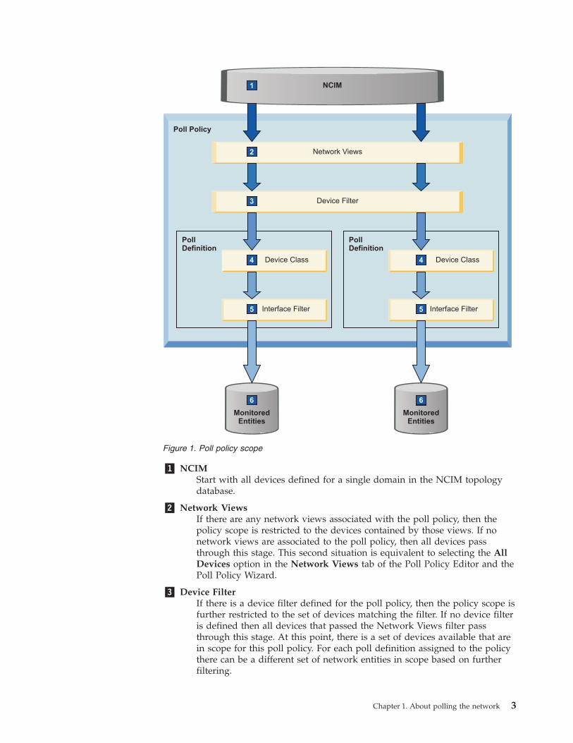
�1� NCIMStart with all devices defined for a single domain in the NCIM topologydatabase.
�2� Network ViewsIf there are any network views associated with the poll policy, then thepolicy scope is restricted to the devices contained by those views. If nonetwork views are associated to the poll policy, then all devices passthrough this stage. This second situation is equivalent to selecting the AllDevices option in the Network Views tab of the Poll Policy Editor and thePoll Policy Wizard.
�3� Device FilterIf there is a device filter defined for the poll policy, then the policy scope isfurther restricted to the set of devices matching the filter. If no device filteris defined then all devices that passed the Network Views filter passthrough this stage. At this point, there is a set of devices available that arein scope for this poll policy. For each poll definition assigned to the policythere can be a different set of network entities in scope based on furtherfiltering.
Poll Policy
Network Views
MonitoredEntities
MonitoredEntities
Device Filter
PollDefinition
Device Class
Interface Filter
PollDefinition
Device Class
Interface Filter
NCIM
6
1
2
3
4
5
6
4
5
6
Figure 1. Poll policy scope
Chapter 1. About polling the network 3
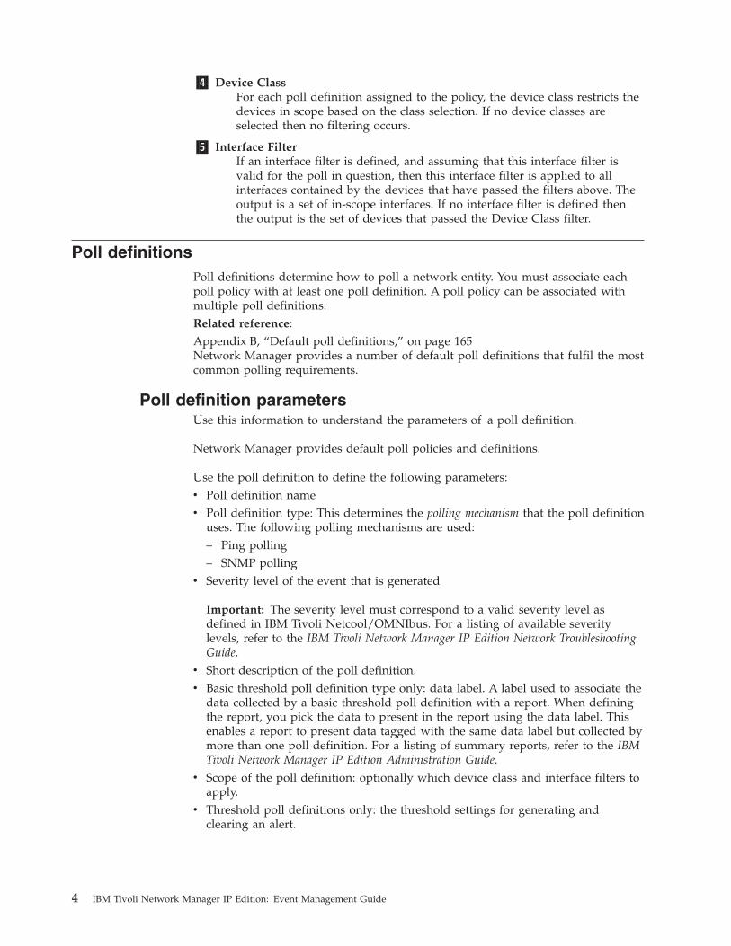
�4� Device ClassFor each poll definition assigned to the policy, the device class restricts thedevices in scope based on the class selection. If no device classes areselected then no filtering occurs.
�5� Interface FilterIf an interface filter is defined, and assuming that this interface filter isvalid for the poll in question, then this interface filter is applied to allinterfaces contained by the devices that have passed the filters above. Theoutput is a set of in-scope interfaces. If no interface filter is defined thenthe output is the set of devices that passed the Device Class filter.
Poll definitionsPoll definitions determine how to poll a network entity. You must associate eachpoll policy with at least one poll definition. A poll policy can be associated withmultiple poll definitions.Related reference:Appendix B, “Default poll definitions,” on page 165Network Manager provides a number of default poll definitions that fulfil the mostcommon polling requirements.
Poll definition parametersUse this information to understand the parameters of a poll definition.
Network Manager provides default poll policies and definitions.
Use the poll definition to define the following parameters:v Poll definition namev Poll definition type: This determines the polling mechanism that the poll definition
uses. The following polling mechanisms are used:– Ping polling– SNMP polling
v Severity level of the event that is generated
Important: The severity level must correspond to a valid severity level asdefined in IBM Tivoli Netcool/OMNIbus. For a listing of available severitylevels, refer to the IBM Tivoli Network Manager IP Edition Network TroubleshootingGuide.
v Short description of the poll definition.v Basic threshold poll definition type only: data label. A label used to associate the
data collected by a basic threshold poll definition with a report. When definingthe report, you pick the data to present in the report using the data label. Thisenables a report to present data tagged with the same data label but collected bymore than one poll definition. For a listing of summary reports, refer to the IBMTivoli Network Manager IP Edition Administration Guide.
v Scope of the poll definition: optionally which device class and interface filters toapply.
v Threshold poll definitions only: the threshold settings for generating andclearing an alert.
4 IBM Tivoli Network Manager IP Edition: Event Management Guide
Polling mechanismsPoll definitions use one of two possible polling mechanisms: ping polling andSNMP polling. All poll definitions are based on either of these mechanisms.
Ping pollingPing polling determines the availability of a network device or interface by usingan ICMP echo request.
The ping process ensures that a device is still present, live, and can be contacted inthe network by periodically sending an ICMP packet to an IP address and waitingfor a response.
A ping poll can have the following results:
SuccessfulA response to the ping packets is received. No alerts are generated.
FailureNo response to the ping packets is received within the time specified in thepoll definition. Alerts are raised for network entities that do not respond.
RestoreA device that was unreachable on the last ping attempt becomes reachableagain. An alert is generated to clear the ping failure alert.
Ping polling can be performed on either a chassis or an interface of a device. In thecase of a chassis, the ICMP packets are sent to the IP address of a main nodedevice. The main node IP address is also associated with an interface. In the caseof interfaces, the ICMP packets are sent to the IP address of each interface.Consequently, if you enable ping polling for both chassis and interfaces, the trafficon main-node IP addresses doubles.
Remember: By default, only the chassis ping poll is enabled on all devices withinthe discovered network topology, with the exception of end-node devices, such asdesktops and printers.
SNMP pollingSNMP polling involves retrieving Management Information Base (MIB) variablesfrom devices in order to determine faulty behavior or connection problems. Faultydevices or faulty connections are then diagnosed by applying predefined formulasto the extracted MIB variables.
Link state polling:
Link state polling monitors changes to the status of the following interface MIBvariables: ifOperStatus and ifAdminStatus.
If the value of one of these MIB variables changes between poll intervals, an eventis raised.
Example
If the value of ifOperStatus was 1 (up) during the previous poll, and changes to 2(down) in the current poll, an event is raised.
Chapter 1. About polling the network 5
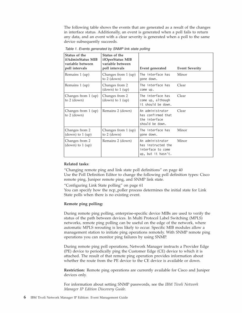
The following table shows the events that are generated as a result of the changesin interface status. Additionally, an event is generated when a poll fails to returnany data, and an event with a clear severity is generated when a poll to the samedevice subsequently succeeds.
Table 1. Events generated by SNMP link state polling
Status of theifAdminStatus MIBvariable betweenpoll intervals
Status of theifOperStatus MIBvariable betweenpoll intervals Event generated Event Severity
Remains 1 (up) Changes from 1 (up)to 2 (down)
The interface hasgone down.
Minor
Remains 1 (up) Changes from 2(down) to 1 (up)
The interface hascome up.
Clear
Changes from 1 (up)to 2 (down)
Changes from 2(down) to 1 (up)
The interface hascome up, althoughit should be down.
Clear
Changes from 1 (up)to 2 (down)
Remains 2 (down) An administratorhas confirmed thatthe interfaceshould be down.
Clear
Changes from 2(down) to 1 (up)
Changes from 1 (up)to 2 (down)
The interface hasgone down.
Minor
Changes from 2(down) to 1 (up)
Remains 2 (down) An administratorhas instructed theinterface to comeup, but it hasn’t.
Minor
Related tasks:“Changing remote ping and link state poll definitions” on page 40Use the Poll Definition Editor to change the following poll definition types: Ciscoremote ping, Juniper remote ping, and SNMP link state.“Configuring Link State polling” on page 61You can specify how the ncp_poller process determines the initial state for LinkState polls when there is no existing event.
Remote ping polling:
During remote ping polling, enterprise-specific device MIBs are used to verify thestatus of the path between devices. In Multi Protocol Label Switching (MPLS)networks, remote ping polling can be useful on the edge of the network, whereautomatic MPLS rerouting is less likely to occur. Specific MIB modules allow amanagement station to initiate ping operations remotely. With SNMP remote pingoperations you can monitor ping failures by using SNMP.
During remote ping poll operations, Network Manager instructs a Provider Edge(PE) device to periodically ping the Customer Edge (CE) device to which it isattached. The result of that remote ping operation provides information aboutwhether the route from the PE device to the CE device is available or down.
Restriction: Remote ping operations are currently available for Cisco and Juniperdevices only.
For information about setting SNMP passwords, see the IBM Tivoli NetworkManager IP Edition Discovery Guide.
6 IBM Tivoli Network Manager IP Edition: Event Management Guide
Prerequisites for remote ping polling
Before remote ping polling can operate, the following prerequisites must be met:v You must have write access to the PE device.v The MPLS paths must have been discovered, and the data transferred to the
NCIM database. In NCIM, the data must be located as follows:– Virtual Private Network Router Forwarding (VRF) tables must be listed in the
VPNRouteForwarding table.– Links from PE to CE devices must be listed in the connects table.
v For Juniper remote ping polling, you also require access to Juniper devicesthrough the View-Based Access Control Model (VACM).
For more information about the VPNRouteForwarding table and the connectstable, see the IBM Tivoli Network Manager IP Edition Topology Database Reference.
Threshold polling:
During threshold polling, predefined formulas are applied to the selected MIBvariables, and if the threshold is exceeded by the MIB variable, then an event isgenerated. A Clear event is generated when the value of the MIB variable eitherfalls below the threshold-value, or falls below a different clear-value.
You can set two thresholds:
Generate thresholdRequired: An event is generated when the value of the MIB variable orvariables exceeds the threshold.
Clear thresholdOptional: A clear-event is generated when the value of the MIB variablefalls below the threshold.
If you do not specify a clear-threshold, the raised event is cleared automaticallywhen the value of the MIB variable or variables no longer exceeds the value of thegenerate-threshold.
Example of threshold polling
The Monitoring Administrator wants to identify all Cisco 29xx routers that haveCPU usage greater than 75%. Using SNMP polling, the administrator can monitorthe behavior of all Cisco 29xx routers in the network, and define that an event isgenerated for each of these routers when their CPU usage exceeds 75%. Aclear-threshold can also be set to generate a notification when CPU usage dropsbelow 60%; if no clear-threshold is specified, a clear-event is generated when theCPU usage no longer exceeds 75%.
Basic and generic threshold polling
Use basic threshold polling to apply simple formulas to the MIB variables, or forfiltering the scope at device and interface level. To filter at interface level, the polldefinition must be set up for interface filtering.
Use generic threshold polling for complex formulas, or for filtering the scope atdevice level only.
Chapter 1. About polling the network 7
Poll definition typesEach poll definition is based on a poll definition type. Poll definition types can begrouped according to the polling mechanism that they use.
Based on the polling mechanisms, the poll definition type restricts the scope of thepoll operation in which it is used.
Ping polling mechanism
The ping polling mechanism has the following poll definition types:
Chassis pingUsed for pinging the management interface of a network device or themain interface of an end-node.
Interface pingUsed for ping operations on interfaces within devices. An interface pingpoll definition has optional interface-level filtering.
SNMP polling mechanism
The SNMP polling mechanism has the following poll definition types:
Generic thresholdUsed for setting formulas to apply against MIB variables. A genericthreshold poll definition consists of the following thresholds:
Trigger thresholdRequired: An event is generated when the value of the MIBvariable or variables exceeds the threshold.
Clear thresholdOptional: A Clear event is generated when the value of the MIBvariable falls below the threshold.
Basic thresholdUse a basic threshold to collect poll data for a single MIB variable orexpression. You can present the data collected in reports or display it inMIB graphs. An event is generated when the trigger threshold conditiondefined in the poll definition is met, and is cleared when the clearthreshold condition is met.
SNMP Link stateUsed for checking the administrative and operational status. An SNMPlink state poll definition has optional interface-level filtering.
Cisco remote pingUsed for checking the availability of devices by using Cisco-specific MIBs.
Juniper remote pingFor checking the availability of devices by using Juniper-specific MIBs.
8 IBM Tivoli Network Manager IP Edition: Event Management Guide
Data labelsData labels are a mechanism that allows grouping of multiple poll definitions thatcollect the same poll data within a single report. Data labels are only available inbasic threshold poll definitions. By default the data label takes the same name asthe poll definition but you can change this to meet your data labeling needs.
The following examples describe the use of data labels to enable a single report toretrieve data from multiple poll definitions. A number of Network Managersummary reports use data labels by default. For a listing of summary reports, referto the IBM Tivoli Network Manager IP Edition Administration Guide.
Multiple vendor-specific poll definitions
A summary report that presents data on the percentage usage of memory acrossdifferent vendor devices must retrieve poll data from multiple vendor-specific polldefinitions. By defining a common memoryPercentageUsage data label within eachof the vendor-specific poll definitions, the data retrieved by each of these differentpoll definitions can be grouped within one report.
Poll definitions with different thresholds and event severities
A summary report that presents data on inbound discards on device interfacesretrieves data from multiple poll definitions. Each of these poll definitions collectsthe same poll data but applies different thresholds and event severities to this data.By defining a common ifInDiscards data label within each of the different polldefinitions, the data retrieved by each of these poll definitions can be groupedwithin a single report.
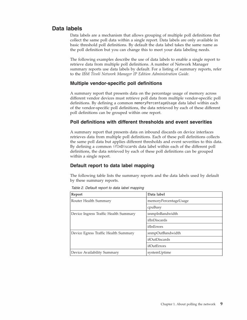
Default report to data label mapping
The following table lists the summary reports and the data labels used by defaultby these summary reports.
Table 2. Default report to data label mapping
Report Data label
Router Health Summary memoryPercentageUsage
cpuBusy
Device Ingress Traffic Health Summary snmpInBandwidth
ifInDiscards
ifInErrors
Device Egress Traffic Health Summary snmpOutBandwidth
ifOutDiscards
ifOutErrors
Device Availability Summary systemUptime
Chapter 1. About polling the network 9
Ping polling properties and metricsFor chassis and interface ping polls, you can specify ping properties such astimeout periods and number of ping retries. You can also collect ping metrics, suchas response time and packet loss.
You can specify the following ping properties when creating a chassis or interfaceping poll.
TimeoutSpecify, in milliseconds, how long the polling process should wait for aresponse from the target device before sending a new ping packet.
RetriesSpecify how many times the polling process should attempt to ping thetarget device before giving up. When Packet Loss metric collection isenabled, the polling process sends this number of ping packets regardlessof whether a response is received.
Payload sizeSelect the size of the ICMP packet to be used for the ping request. Selectthe default (32 bytes) or choose a custom size. This setting overrides thevalue of IcmpData in the NcPollerSchema.cfg configuration file.
CAUTION:Using a size smaller than 32 bytes may result in packets being dropped.
You can collect the following ping metrics when creating a chassis or interface pingpoll.
Response timeYou can opt to collect data on the round trip time for ping tests. This ismeasured in milliseconds. When Packet Loss is also being collected, this isthe average response time for each successful test.
Packet lossYou can opt to collect data on the number of ping packets for which thepolling process did not receive a response. This is stored as a percentage.
Multibyte data in poll definitionsIf you are running Network Manager in a domain that uses multibyte characterssuch as Simplified Chinese, then you must ensure that Network Manager isconfigured to handle multibyte characters before you configure basic or genericthreshold poll definitions.
For information on how to configure Network Manager to use multibytecharacters, see the IBM Tivoli Network Manager IP Edition Installation andConfiguration Guide.
10 IBM Tivoli Network Manager IP Edition: Event Management Guide
Chapter 2. Enabling and disabling polls
To activate Network Manager polling, you must enable the poll policies. If anetwork entity is off the network, disable the poll policy that polls that entity.
Tip: You can change the settings for a poll before enabling it. When creating yourown poll policies, use the default poll policies as examples.
By default, only the chassis ping poll is enabled on all devices within thediscovered network topology, with the exception of end-node devices, such asdesktops and printers.
Note: If you are enabling poll policies for a large number of devices, it is bestpractice to wait until the poll policies are fully enabled before using the NetworkPolling GUI to make any changes to the poll policies. Any changes to poll policiescauses the Polling engine, ncp_poller, to restart, and this can have unpredictableresults if ncp_poller was in the process of enabling poll policies. Use the Statusand Enabled columns in the Configure Poll Policies section of the Network PollingGUI to determine if a poll policy has been enabled.
To enable or disable polls:1. Click Administration > Network > Network Polling.2. Select the check box next to the required policy or policies.3. Optional: To enable the selected policy or policies, click Enable Selected
Policies .
4. Optional: To disable policies, click Disable Selected Policies .5. Click OK.
© Copyright IBM Corp. 2006, 2013 11

12 IBM Tivoli Network Manager IP Edition: Event Management Guide
Chapter 3. Creating polls
Create polls if the existing default poll policies and definitions do not meet yourrequirements. Either customize a copy of an existing or default poll, or create anew poll from scratch.
Use the Poll Policy Editor to create a fully-featured poll policy with multiple polldefinitions and complete scoping facilities. Alternatively you can use the PollPolicy Wizard to guide you through the creation of a poll policy; however, you canonly use the wizard to create a simple poll policy with a single existing polldefinition and limited scoping facilities.
Remember: The system enforces unique poll policy names within a domain.
Note: If you are enabling poll policies for a large number of devices, it is bestpractice to wait until the poll policies are fully enabled before using the NetworkPolling GUI to make any changes to the poll policies. Any changes to poll policiescauses the Polling engine, ncp_poller, to restart, and this can have unpredictableresults if ncp_poller was in the process of enabling poll policies. Use the Statusand Enabled columns in the Configure Poll Policies section of the Network PollingGUI to determine if a poll policy has been enabled.Related concepts:“Poll definition types” on page 8Each poll definition is based on a poll definition type. Poll definition types can begrouped according to the polling mechanism that they use.Related tasks:Chapter 5, “Changing polls,” on page 29To change a poll, make changes to either the poll policy, or the poll definition onwhich the poll is based.“Changing poll definitions” on page 34Change existing poll definitions to customize them for your polling requirements.You change poll definitions in the Poll Definition Editor; the steps you follow differdepending on the poll definition type.“Creating adaptive polls” on page 55Create adaptive polls to enable the system to dynamically react to events on thenetwork.
Creating fully featured poll policiesUse the Poll Policy Editor to create a fully-featured poll policy with multiple polldefinitions and complete scoping features.
Using the Poll Policy Editor you can create a poll policy with the followingfeatures:v Multiple poll definitions. You can use existing poll definitions or you can create
new poll definitions.v Network views. You can restrict the set of devices to poll to those contained by
the selected network views.v Device Filter. You can further refine the list of devices selected by the network
views using this simple filter on the mainNodeDetails table.
© Copyright IBM Corp. 2006, 2013 13

Note: You can further restrict the poll policy scope by filtering the scope of each ofthe poll definitions contained within this poll policy. You can filter poll definitionscope by device class and by interface.1. Click Administration > Network > Network Polling.2. Create a new policy by doing one of the following:
v To create a new policy from scratch, click Add New . The Poll PolicyEditor opens
v To clone an existing policy, perform the following steps:a. In the Select column select the check box next to the required row and
click Copy Selected Items .b. Click OK. The copy is named using the following convention:
policyname_1, where policyname is the name of the copied policy. Forexample, if you copied the policy bgpPeerState, then the copy will benamed bgpPeerState_1. Poll policies are ordered alphabetically so in thisexample, the copy bgpPeerState_1 would appear in the list immediatelyafter the copied policy bgpPeerState.
c. Click the name of the copy of the poll policy in the list to open the PollPolicy Editor.
3. From the Poll Policy Properties tab, specify a value for each property:
Name Type the unique name that you want to give the poll policy. Onlyalphanumeric characters, spaces and underscores are allowed.
Poll EnabledSelect this check box to enable the poll policy. Ensure that you havespecified at least one poll definition for the policy before enabling it.
Poll DefinitionsUse this table to specify one or more poll definitions for the pollpolicy.
RefreshRefreshes the data in the table. This updates the table withany changes made by other users since you logged on or sinceyou last clicked Refresh.
Delete Selected Item(s)Deletes the selected rows.
Add Poll Definition(s) to this PolicyOpens the Poll Definitions panel where you can specify one ormore poll definitions to add to the poll policy.
SearchSearches the table for text entered in the Search field. Bydefault the search is performed on all of the columns in thetable. Click the down arrow to the left of the Search field tolimit the search to one or more columns in the table.v Select the checkboxes corresponding to the columns that
you want to limit the search to.v Select All Columns to revert to the default search settings.v Click OK once you have made your selection.
14 IBM Tivoli Network Manager IP Edition: Event Management Guide

Poll Definitions tableThe list of poll definitions attached to this poll policy ispresented in a table. You can perform the following actions onthis table. Any settings made are valid for this session only.
Hide ToolbarHides the toolbar. If the toolbar is hidden, click ShowToolbar to show the toolbar.
Sort ColumnClick the column header to sort that column indescending order. Click the column a second time tosort the column in ascending order. Further clickstoggle the column between descending and ascendingorder. The meaning of ascending and descendingorder varies according to the type of data in thecolumn:
Alphabetical dataAscending order orders the data from a to z.Descending order orders the data from z to a.
Numerical dataAscending order orders the data from lowestto highest. Descending order orders the datafrom higest to lowest.
Icon Ascending order orders the icons from thehighest to lowest value associated with theicon. Descending order orders the icons fromthe lowest to highest value associated with theicon. The values associated with each icon arelisted below.
Resize a columnClick and drag the vertical line separator to the rightof the column heading.
Select All/Clear AllSelect the check box to select all rows. If all rows are selected,clear the check box to clear all rows. Select the check box nextto a row to select a single row or to clear a single selectedrow.
Store? Select the check box to store data collected by this polldefinition for reporting and historical MIB graphing purposes.
Note: This option is only available for poll definitions of typeBasic Threshold.
Name The name of a poll definition attached to this poll policy. Clickthe name to edit the properties of this poll definition.
Type The type of poll definition.
Status Indicates whether the poll definition is in error. The full list ofvalues is provided in the following table.
Chapter 3. Creating polls 15
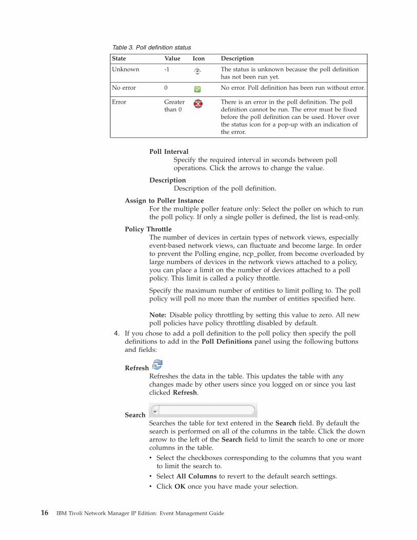
Table 3. Poll definition status
State Value Icon Description
Unknown -1 The status is unknown because the poll definitionhas not been run yet.
No error 0 No error. Poll definition has been run without error.
Error Greaterthan 0
There is an error in the poll definition. The polldefinition cannot be run. The error must be fixedbefore the poll definition can be used. Hover overthe status icon for a pop-up with an indication ofthe error.
Poll IntervalSpecify the required interval in seconds between polloperations. Click the arrows to change the value.
DescriptionDescription of the poll definition.
Assign to Poller InstanceFor the multiple poller feature only: Select the poller on which to runthe poll policy. If only a single poller is defined, the list is read-only.
Policy ThrottleThe number of devices in certain types of network views, especiallyevent-based network views, can fluctuate and become large. In orderto prevent the Polling engine, ncp_poller, from become overloaded bylarge numbers of devices in the network views attached to a policy,you can place a limit on the number of devices attached to a pollpolicy. This limit is called a policy throttle.
Specify the maximum number of entities to limit polling to. The pollpolicy will poll no more than the number of entities specified here.
Note: Disable policy throttling by setting this value to zero. All newpoll policies have policy throttling disabled by default.
4. If you chose to add a poll definition to the poll policy then specify the polldefinitions to add in the Poll Definitions panel using the following buttonsand fields:
RefreshRefreshes the data in the table. This updates the table with anychanges made by other users since you logged on or since you lastclicked Refresh.
SearchSearches the table for text entered in the Search field. By default thesearch is performed on all of the columns in the table. Click the downarrow to the left of the Search field to limit the search to one or morecolumns in the table.v Select the checkboxes corresponding to the columns that you want
to limit the search to.v Select All Columns to revert to the default search settings.v Click OK once you have made your selection.
16 IBM Tivoli Network Manager IP Edition: Event Management Guide

Poll Definitions tableThe complete list of poll definitions defined on the system. Polldefinitions already attached to this poll policy have a greyed outcheckbox. You can perform the following actions on this table. Anysettings made are valid for this session only.
Hide ToolbarHides the toolbar. If the toolbar is hidden, click Show Toolbar
to show the toolbar.
Sort ColumnClick the column header to sort that column in descendingorder. Click the column a second time to sort the column inascending order. Further clicks toggle the column betweendescending and ascending order. The meaning of ascendingand descending order varies according to the type of data inthe column:
Alphabetical dataAscending order orders the data from a to z.Descending order orders the data from z to a.
Numerical dataAscending order orders the data from lowest tohighest. Descending order orders the data from higestto lowest.
Icon Ascending order orders the icons from the highest tolowest value associated with the icon. Descendingorder orders the icons from the lowest to highestvalue associated with the icon. The values associatedwith each icon are listed below.
Resize a columnClick and drag the vertical line separator to the right of thecolumn heading.
Select All/Clear AllSelect the check box to select all rows. If all rows are selected, clearthe check box to clear all rows. Select the check box next to a row toselect a single row or to clear a single selected row.
Name The name of a poll definition attached to this poll policy. Click thename to edit the properties of this poll definition.
Type The type of poll definition.
DescriptionDescription of the poll definition.
Store Poll DataSelect this check box to store the poll data so that it can besubsequently retrieved for reporting. The data is stored in thencpolldata database.
Restriction: Storage of polled data is not supported for the CiscoRemote Ping, the Juniper Remote Ping, and the Generic Thresholdpoll definitions.
IntervalSpecify the required interval in seconds between poll operations. Clickthe arrows to change the value.
Chapter 3. Creating polls 17

5. Click the Network Views tab to set the poll scope. In the Network Viewstree, select the check boxes of the required network views. The NetworkViews tree displays only those network views that belong to the networkdomain in which this poll policy is defined.Attention: If you select the All Devices option, then the system polls alldevices that match the scope defined in the Device Filter tab. If no scope isset then, if you select the All Devices option, the poll that you create will pollall devices in the current network domain.You can further filter the poll policy scope by filtering the scope of each of thepoll definitions contained within this poll policy. You can filter poll definitionscope by device class and by interface.
6. Optional: Click the Device Filter tab. This filters on devices on themainNodeDetails device table only. Define the filter by using one of thefollowing methods:v Type an SQL WHERE statement in the field in the Filter column.
v Click Edit to set up the filter by using the Filter Builder.7. Optional: In the Filter Builder, build the required query on one of the two tabs
and then click OK:v On the Basic tab, select a field, a comparator, and type a value. Use the %
character as a wildcard. The field is restricted to the selected attribute table.v On the Advanced tab, type the required SQL WHERE statement.
The information that you enter on the Basic tab is automatically written to theAdvanced tab.
8. Optional: To add filters on other attribute tables, click Add new row , andrepeat the steps to edit the row and build the filter.
9. Optional: To combine multiple filters, click All or Any:v All: Only network entities that match all the specified filters are polled. For
example, if you create two filters, a network entity must match both filters.v Any: Network entities that match any of the specified filters are polled.
10. Click Save.Related concepts:“Poll policy scope” on page 2The poll policy scope defines the devices or device interfaces to be polled.Related tasks:“Administering poll policy throttling” on page 60You can configure how much data is transferred by the Polling engine, ncp_poller,and how often. You might want to adjust polling bandwidth to avoid networkcongestion or to reduce the impact of large numbers of polling events occurringsimultaneously.Related reference:Appendix D, “Syntax for poll definition expressions,” on page 175Use this information to understand how to build complex threshold expressions touse in basic and generic threshold poll definitions.
18 IBM Tivoli Network Manager IP Edition: Event Management Guide
Creating simple poll policiesUse the Poll Policy Wizard to guide you through the creation of a poll policy;however, you can only use the wizard to create a simple poll policy with a singleexisting poll definition and limited scoping features.
Using the Poll Policy Wizard you can create a simple poll policy with thefollowing limited poll definition and scoping features.v Single poll definition. You can use a single existing poll definition only.v Network views. You can restrict the set of devices to poll to those contained by
the selected network views.
Restriction: The Poll Policy Wizard does not provide a device filter to refine thelist of devices selected by the network views.
If you require a fully-featured poll policy with multiple poll definitions and fullscoping features, then use the Poll Policy Editor.1. Click Administration > Network > Network Polling.
2. Click Launch Poll Configuration Wizard .3. Click Next. Complete the Poll Policy Details page as follows:
Name Specify a name for the poll policy. Only alphanumeric characters,spaces and underscores are allowed.
IntervalSpecify the required interval in seconds between poll operations. Clickthe arrows to change the value.
Poll EnabledSpecify whether the poll should be enabled. The poll is enabled bydefault. To disable the poll, clear this check box.
Store Poll DataSelect this check box to store the poll data so that it can besubsequently retrieved for reporting. The data is stored in thencpolldata database.
Restriction: Storage of polled data is not supported for the CiscoRemote Ping, the Juniper Remote Ping, and the Generic Threshold polldefinitions.
DefinitionSelect a poll definition from the list.
4. Click Next. On the Poll Policy Scope Details page, select the check boxes of therequired network views. In the Network Views tree, select the check boxes ofthe required network views. The Network Views tree displays only thosenetwork views that belong to the network domain in which this poll policy isdefined.Attention: If you select the All Devices option, the poll that you create willpoll all devices in the current network domain.
5. Click Next. On the Poll Policy Summary page, review the information that youspecified and click Finish.
Chapter 3. Creating polls 19

Related concepts:“Poll policy scope” on page 2The poll policy scope defines the devices or device interfaces to be polled.Related reference:Appendix D, “Syntax for poll definition expressions,” on page 175Use this information to understand how to build complex threshold expressions touse in basic and generic threshold poll definitions.
20 IBM Tivoli Network Manager IP Edition: Event Management Guide
Chapter 4. Creating new poll definitions
Use the Poll Definition Editor to guide you through the steps of creating a newpoll definition.
Before you create or change a poll definition, view an existing poll definition todetermine whether you can use it as a template to create a new poll definition.
Remember: The system enforces unique poll definition names within a domain.
Because the poll definition types differ, the Poll Definition Editor displays differentpages depending on which poll definition type you select.Related tasks:“Changing poll definitions” on page 34Change existing poll definitions to customize them for your polling requirements.You change poll definitions in the Poll Definition Editor; the steps you follow differdepending on the poll definition type.Chapter 3, “Creating polls,” on page 13Create polls if the existing default poll policies and definitions do not meet yourrequirements. Either customize a copy of an existing or default poll, or create anew poll from scratch.Related reference:Appendix B, “Default poll definitions,” on page 165Network Manager provides a number of default poll definitions that fulfil the mostcommon polling requirements.
Creating basic threshold poll definitionsCreate a basic threshold poll definition to run simple formulas against MIBvariables, or to create threshold polls with interface-level filtering.
Before you create or change a poll definition, view an existing poll definition todetermine whether you can use it as a template to create a new poll definition.
To create a basic threshold poll definition:1. Click Administration > Network > Network Polling.
2. Click Add New . The New Poll Definition Type Selection page isdisplayed.
3. Select Basic threshold from the list and click OK.4. In the Poll Definition Editor, under the General tab, complete the General
Properties fields as follows:
Name Specify a unique name for the poll definition. Only alphanumericcharacters, spaces and underscores are allowed.
Type This field is disabled. The Polling engine, ncp_poller, automaticallypopulates this field once this poll definition is included as part of anenabled poll policy. The value assigned to the event ID is POLL-pollde
Event IDThis field is disabled. The Polling engine, ncp_poller, automatically
© Copyright IBM Corp. 2006, 2013 21
populates this field once this poll definition is included as part of anenabled policy. The Event ID field is populated as follows:v If this is a new poll definition, then the Event ID field is populated
with the value POLL-polldef, where polldef is the name of thecurrent poll definition.
v If you created a poll definition by copying an existing poll definition,then the Event ID contains the same value as the copied polldefinition.
Note: Some of the older default polls have Event ID fields that do notuse the POLL-polldef naming convention.
Event SeveritySpecify a valid number for the severity. The severity level mustcorrespond to a valid severity level as defined in IBM TivoliNetcool/OMNIbus. For a listing of available severity levels, refer to theIBM Tivoli Network Manager IP Edition Network Troubleshooting Guide
DescriptionType a short description of the poll definition.
Data LabelClick the data label list and select one of the data labels from the list.By default the data label takes the same name as the current polldefinition. To define a new data label, select <Add New Data Label>. Thefield to the right of the list becomes active. Type the name of the newdata label in this field.
5. Click the Classes tab. In the Classes tree, select the check boxes of the requiredclasses.Attention: If you leave all classes unchecked, then the system polls all devicesthat match the scope defined in the poll policy that uses this poll definition.
6. Optional: Click the Interface Filter tab and build the filter against the requiredfields. The Table field is prepopulated with the interfaces table.
7. Click the Poll Data tab and specify the required formula:v To specify a MIB Object Identifier (OID), select Single OID. Specify the
current or delta value of the required MIB variable and type the variable intothe next field.
v To specify a complex expression, select Expression and type the formula intothe field.
To select variables directly from the MIB tree, click Add MIB Object . Fromthe MIB tree, you can specify the current or previous values of the selected MIBvariable, or resolve the current value of the variable to the SNMP index.
8. Click the Threshold tab and specify the formulas for triggering events andclearing events. The MIB OID or expression that you specified on the Poll Datatab is written automatically into the formulas.a. In the Trigger Threshold area, select a comparator from the list and type
the value against which to filter the MIB OID.b. In the Description field, type a meaningful description of the trigger
formula. Add the MIB variable to the description in parentheses. Thedescription is displayed in the AEL when and event is raised. For example:CPU usage high (avgBusy5=)
c. To insert the underlying eval statement into the description, position the
cursor before the closing parenthesis, click Add MIB Object , and
22 IBM Tivoli Network Manager IP Edition: Event Management Guide
navigate to the specified variable. Specify whether the current or previousvalue of the variable is evaluated, or whether the value is resolved to theSNMP index, and click OK. The statement is inserted, for example:CPU usage high (avgBusy5=eval(text,"&SNMP.VALUE.sysName"))
d. Repeat steps 8a on page 22 to 8c on page 22 for the Clear Threshold area.9. Click Save.Related concepts:“Multibyte data in poll definitions” on page 10If you are running Network Manager in a domain that uses multibyte characterssuch as Simplified Chinese, then you must ensure that Network Manager isconfigured to handle multibyte characters before you configure basic or genericthreshold poll definitions.“Poll policy scope” on page 2The poll policy scope defines the devices or device interfaces to be polled.Related reference:“Example basic threshold expression” on page 42Use this example basic threshold expression to understand how to composecomplex basic threshold expressions.Appendix D, “Syntax for poll definition expressions,” on page 175Use this information to understand how to build complex threshold expressions touse in basic and generic threshold poll definitions.
Creating generic threshold poll definitionsUse the Poll Definition Editor to create new generic threshold poll definitions.
When creating a generic threshold definition, you set formulas and combineformulas.
To create a generic threshold poll definition:1. Click Administration > Network > Network Polling.
2. Click Add New . The New Poll Definition Type Selection page isdisplayed.
3. Select Generic Threshold from the list and click OK.4. In the Poll Definition Editor, under the General tab, complete the General
Properties fields as follows:
Name Specify a unique name for the poll definition. Only alphanumericcharacters, spaces and underscores are allowed.
Type This field is disabled. The Polling engine, ncp_poller, automaticallypopulates this field once this poll definition is included as part of anenabled poll policy. The value assigned to the event ID is POLL-pollde
Event IDThis field is disabled. The Polling engine, ncp_poller, automaticallypopulates this field once this poll definition is included as part of anenabled policy. The Event ID field is populated as follows:v If this is a new poll definition, then the Event ID field is populated
with the value POLL-polldef, where polldef is the name of thecurrent poll definition.
Chapter 4. Creating new poll definitions 23

v If you created a poll definition by copying an existing polldefinition, then the Event ID contains the same value as the copiedpoll definition.
Note: Some of the older default polls have Event ID fields that do notuse the POLL-polldef naming convention.
Event SeveritySpecify a valid number for the severity. The severity level mustcorrespond to a valid severity level as defined in IBM TivoliNetcool/OMNIbus. For a listing of available severity levels, refer tothe IBM Tivoli Network Manager IP Edition Network TroubleshootingGuide
DescriptionType a short description of the poll definition.
5. Click the Classes tab. In the Classes tree, select the check boxes of therequired classes.Attention: If you leave all classes unchecked, then the system polls alldevices that match the scope defined in the poll policy that uses this polldefinition.
6. Optional: Click the Interface Filter tab and build the filter against the requiredfields. The Table field is prepopulated with the interfaces table.
7. Click the Trigger Threshold tab. Build the formula that specifies the thresholdby using one of the following methods:v In the Basic area, use the fields and options to build a formula. To select
values from the MIB tree, click Open MIB Tree .v In the Advanced area, type the required eval statement in Object Query
Language (OQL).8. Specify the message that is displayed in the AEL for the generated event:
a. In the Event description field, type the message.
b. To insert the MIB variables in the field, click Open MIB Tree . Set themessage to include either the current or previous SNMP value, or theSNMP index, and click OK.
9. Required: Click the Clear Threshold tab. Every generic threshold polldefinition requires a clear threshold. Build the formula that specifies thethreshold by using one of the following methods:v In the Basic area, use the fields and options to build a formula. To select
values from the MIB tree, click Open MIB Tree .v In the Advanced area, type the required eval statement in Object Query
Language (OQL).
Tip: If you want the threshold to be cleared manually, create a clear thresholdthat will not be reached.
10. Specify the message that is displayed in the AEL for the generated event:a. In the Event description field, type the message.
b. To insert the MIB variables in the field, click Open MIB Tree . Set themessage to include either the current or previous SNMP value, or theSNMP index, and click OK.
11. Click Save, then click OK.
24 IBM Tivoli Network Manager IP Edition: Event Management Guide
The poll definition is added to the bottom of the list.Related concepts:“Multibyte data in poll definitions” on page 10If you are running Network Manager in a domain that uses multibyte characterssuch as Simplified Chinese, then you must ensure that Network Manager isconfigured to handle multibyte characters before you configure basic or genericthreshold poll definitions.“Poll policy scope” on page 2The poll policy scope defines the devices or device interfaces to be polled.Related reference:“Example generic threshold expression” on page 43Use this example generic threshold expression to understand how to composecomplex generic threshold expressions.Appendix D, “Syntax for poll definition expressions,” on page 175Use this information to understand how to build complex threshold expressions touse in basic and generic threshold poll definitions.
Creating chassis and interface ping poll definitionsUse the Poll Definition Editor to create chassis and interface ping poll definitiontypes.
You perform identical steps to create a poll definition based on all the above polldefinition types.
To create a chassis or interface ping poll definition:1. Click Administration > Network > Network Polling.
2. Click Add New . The New Poll Definition Type Selection page isdisplayed.
3. Select Chassis Ping or Interface Ping from the list.4. In the Poll Definition Editor, under the General tab, complete the General
Properties fields as follows:
Name Specify a unique name for the poll definition. Only alphanumericcharacters, spaces and underscores are allowed.
Type This field is disabled. The Polling engine, ncp_poller, automaticallypopulates this field once this poll definition is included as part of anenabled poll policy. The value assigned to the event ID is POLL-pollde
Event IDThis field is disabled. The Polling engine, ncp_poller, automaticallypopulates this field once this poll definition is included as part of anenabled policy. The Event ID field is populated as follows:v If this is a new poll definition, then the Event ID field is populated
with the value POLL-polldef, where polldef is the name of thecurrent poll definition.
v If you created a poll definition by copying an existing poll definition,then the Event ID contains the same value as the copied polldefinition.
Note: Some of the older default polls have Event ID fields that do notuse the POLL-polldef naming convention.
Chapter 4. Creating new poll definitions 25
Event SeveritySpecify a valid number for the severity. The severity level mustcorrespond to a valid severity level as defined in IBM TivoliNetcool/OMNIbus. For a listing of available severity levels, refer to theIBM Tivoli Network Manager IP Edition Network Troubleshooting Guide
DescriptionType a short description of the poll definition.
5. Click the Classes tab. In the Classes tree, select the check boxes of the requiredclasses.Attention: If you leave all classes unchecked, then the system polls all devicesthat match the scope defined in the poll policy that uses this poll definition.
6. Optional: Click the Interface Filter tab and build the filter against the requiredfields. The Table field is prepopulated with the interfaces table.
7. Click the Ping tab and complete the Ping Properties fields as follows:
TimeoutSpecify, in milliseconds, how long the polling process should wait for aresponse from the target device before sending a new ping packet.
RetriesSpecify how many times the polling process should attempt to ping thetarget device before giving up. When Packet Loss metric collection isenabled, the polling process sends this number of ping packetsregardless of whether a response is received.
Collect Ping Metrics
Response TimeCheck the box to collect the time taken by devices to respondto a ping request.
Packet LossCheck the box to collect data about lost packets.
Payload SizeSelect the size of the ICMP packet to be used for the ping request.Select the default (32 bytes) or choose a custom size. This settingoverrides the value of IcmpData in the NcPollerSchema.cfgconfiguration file.
CAUTION:Using a size smaller than 32 bytes may result in packets beingdropped.
8. Click Save, then click OK.Related concepts:“Poll policy scope” on page 2The poll policy scope defines the devices or device interfaces to be polled.
26 IBM Tivoli Network Manager IP Edition: Event Management Guide
Creating remote ping and link state poll definitionsUse the Poll Definition Editor to create new poll definitions with the following polldefinition types: Cisco remote ping, Juniper remote ping, SNMP link state.
You perform identical steps to create a poll definition based on all the above polldefinition types.
To create a remote ping poll definition, or an SNMP link state poll definition:1. Click Administration > Network > Network Polling.
2. Click Add New . The New Poll Definition Type Selection page isdisplayed.
3. Select the required definition type from the list:v Cisco Remote Ping
v Juniper Remote Ping
v SNMP Link State
4. Click OK.5. In the Poll Definition Editor, under the General tab, complete the General
Properties fields as follows:
Name Specify a unique name for the poll definition. Only alphanumericcharacters, spaces and underscores are allowed.
Type This field is disabled. The Polling engine, ncp_poller, automaticallypopulates this field once this poll definition is included as part of anenabled poll policy. The value assigned to the event ID is POLL-pollde
Event IDThis field is disabled. The Polling engine, ncp_poller, automaticallypopulates this field once this poll definition is included as part of anenabled policy. The Event ID field is populated as follows:v If this is a new poll definition, then the Event ID field is populated
with the value POLL-polldef, where polldef is the name of thecurrent poll definition.
v If you created a poll definition by copying an existing poll definition,then the Event ID contains the same value as the copied polldefinition.
Note: Some of the older default polls have Event ID fields that do notuse the POLL-polldef naming convention.
Event SeveritySpecify a valid number for the severity. The severity level mustcorrespond to a valid severity level as defined in IBM TivoliNetcool/OMNIbus. For a listing of available severity levels, refer to theIBM Tivoli Network Manager IP Edition Network Troubleshooting Guide
DescriptionType a short description of the poll definition.
6. Click the Classes tab. In the Classes tree, select the check boxes of the requiredclasses.Attention: If you leave all classes unchecked, then the system polls all devicesthat match the scope defined in the poll policy that uses this poll definition.
Chapter 4. Creating new poll definitions 27

7. Optional: Click the Interface Filter tab and build the filter against the requiredfields. The Table field is prepopulated with the interfaces table.
8. Click Save, then click OK.Related concepts:“Poll policy scope” on page 2The poll policy scope defines the devices or device interfaces to be polled.
28 IBM Tivoli Network Manager IP Edition: Event Management Guide
Chapter 5. Changing polls
To change a poll, make changes to either the poll policy, or the poll definition onwhich the poll is based.Related concepts:“Poll policies” on page 2Poll policies contain all the properties of a network poll operation. They specifyhow often a device is polled, the type of polling mechanisms employed to do thepolling, and the devices to be polled.“Poll definitions” on page 4Poll definitions determine how to poll a network entity. You must associate eachpoll policy with at least one poll definition. A poll policy can be associated withmultiple poll definitions.Related tasks:Chapter 3, “Creating polls,” on page 13Create polls if the existing default poll policies and definitions do not meet yourrequirements. Either customize a copy of an existing or default poll, or create anew poll from scratch.Related reference:Appendix A, “Default poll policies,” on page 159Network Manager provides a set of default poll policies. Use this information tofamiliarize yourself with these policies.
Changing poll policiesUse the Poll Policy Editor to change the settings of existing poll policies.
Before you create or change a poll policy, view an existing poll policy to determinewhether you can use the poll as a template to create a new poll policy.
Note: If you are enabling poll policies for a large number of devices, it is bestpractice to wait until the poll policies are fully enabled before using the NetworkPolling GUI to make any changes to the poll policies. Any changes to poll policiescauses the Polling engine, ncp_poller, to restart, and this can have unpredictableresults if ncp_poller was in the process of enabling poll policies. Use the Statusand Enabled columns in the Configure Poll Policies section of the Network PollingGUI to determine if a poll policy has been enabled.
To change a poll policy:1. Click Administration > Network > Network Polling.2. Click the required poll policy. The Poll Policy Editor is displayed; the settings
of the selected poll policy are automatically loaded into the fields.3. Under Poll Policy Properties, specify a value for the following fields:
Name Type the unique name that you want to give the poll policy. Onlyalphanumeric characters, spaces and underscores are allowed.
Poll EnabledSelect this check box to enable the poll policy. Ensure that you havespecified at least one poll definition for the policy before enabling it.
© Copyright IBM Corp. 2006, 2013 29
Poll DefinitionsUse this table to specify one or more poll definitions for the poll policy.
RefreshRefreshes the data in the table. This updates the table with anychanges made by other users since you logged on or since youlast clicked Refresh.
Delete Selected Item(s)Deletes the selected rows.
Add Poll Definition(s) to this PolicyOpens the Poll Definitions panel where you can specify one ormore poll definitions to add to the poll policy.
SearchSearches the table for text entered in the Search field. Bydefault the search is performed on all of the columns in thetable. Click the down arrow to the left of the Search field tolimit the search to one or more columns in the table.v Select the checkboxes corresponding to the columns that you
want to limit the search to.v Select All Columns to revert to the default search settings.v Click OK once you have made your selection.
Poll Definitions tableThe list of poll definitions attached to this poll policy ispresented in a table. You can perform the following actions onthis table. Any settings made are valid for this session only.
Hide ToolbarHides the toolbar. If the toolbar is hidden, click ShowToolbar to show the toolbar.
Sort ColumnClick the column header to sort that column indescending order. Click the column a second time tosort the column in ascending order. Further clickstoggle the column between descending and ascendingorder. The meaning of ascending and descending ordervaries according to the type of data in the column:
Alphabetical dataAscending order orders the data from a to z.Descending order orders the data from z to a.
Numerical dataAscending order orders the data from lowest tohighest. Descending order orders the data fromhigest to lowest.
Icon Ascending order orders the icons from thehighest to lowest value associated with theicon. Descending order orders the icons fromthe lowest to highest value associated with theicon. The values associated with each icon arelisted below.
30 IBM Tivoli Network Manager IP Edition: Event Management Guide
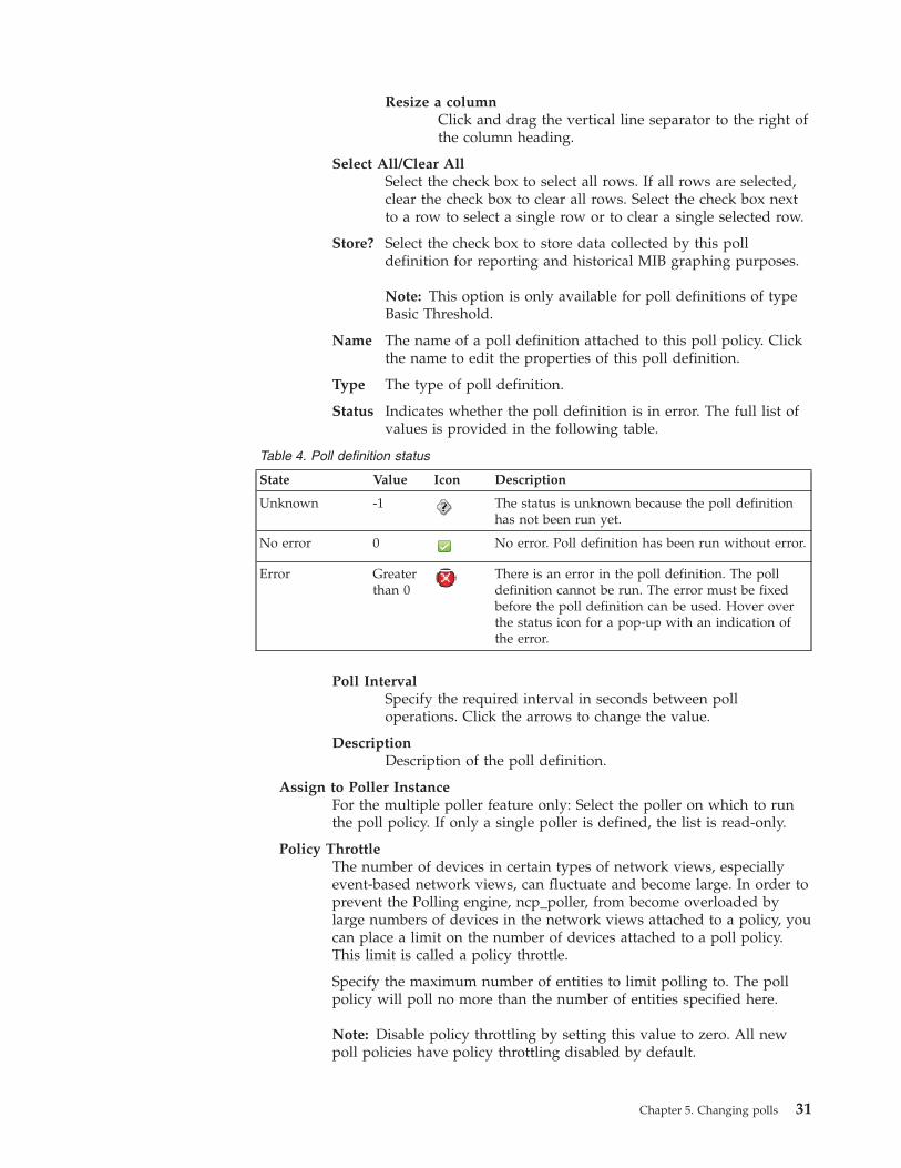
Resize a columnClick and drag the vertical line separator to the right ofthe column heading.
Select All/Clear AllSelect the check box to select all rows. If all rows are selected,clear the check box to clear all rows. Select the check box nextto a row to select a single row or to clear a single selected row.
Store? Select the check box to store data collected by this polldefinition for reporting and historical MIB graphing purposes.
Note: This option is only available for poll definitions of typeBasic Threshold.
Name The name of a poll definition attached to this poll policy. Clickthe name to edit the properties of this poll definition.
Type The type of poll definition.
Status Indicates whether the poll definition is in error. The full list ofvalues is provided in the following table.
Table 4. Poll definition status
State Value Icon Description
Unknown -1 The status is unknown because the poll definitionhas not been run yet.
No error 0 No error. Poll definition has been run without error.
Error Greaterthan 0
There is an error in the poll definition. The polldefinition cannot be run. The error must be fixedbefore the poll definition can be used. Hover overthe status icon for a pop-up with an indication ofthe error.
Poll IntervalSpecify the required interval in seconds between polloperations. Click the arrows to change the value.
DescriptionDescription of the poll definition.
Assign to Poller InstanceFor the multiple poller feature only: Select the poller on which to runthe poll policy. If only a single poller is defined, the list is read-only.
Policy ThrottleThe number of devices in certain types of network views, especiallyevent-based network views, can fluctuate and become large. In order toprevent the Polling engine, ncp_poller, from become overloaded bylarge numbers of devices in the network views attached to a policy, youcan place a limit on the number of devices attached to a poll policy.This limit is called a policy throttle.
Specify the maximum number of entities to limit polling to. The pollpolicy will poll no more than the number of entities specified here.
Note: Disable policy throttling by setting this value to zero. All newpoll policies have policy throttling disabled by default.
Chapter 5. Changing polls 31
4. Click the Network Views tab. In the Network Views tree, select the checkboxes of the required network views. The Network Views tree displays onlythose network views that belong to the network domain in which this pollpolicy is defined.Attention: If you select the All Devices option, then the system polls alldevices that match the scope defined in the Device Filter tab. If no scope is setthen, if you select the All Devices option, the poll that you create will poll alldevices in the current network domain.
5. Optional: Click the Device Filter tab. This filters on devices on themainNodeDetails device table only. Define the filter by using one of thefollowing methods:v Type an SQL WHERE statement in the field in the Filter column.
v Click Edit to set up the filter by using the Filter Builder.6. In the Filter Builder, build the required query on one of the two tabs and then
click OK:v On the Basic tab, select a field, a comparator, and type a value. Use the %
character as a wildcard. The field is restricted to the selected attribute table.v On the Advanced tab, type the required SQL WHERE statement.
The information that you enter on the Basic tab is automatically written to theAdvanced tab.
7. To add filters on other attribute tables, click Add new row , and repeat thesteps to edit the row and build the filter.
8. To combine multiple filters, click All or Any:v All: Only network entities that match all the specified filters are polled. For
example, if you create two filters, a network entity must match both filters.v Any: Network entities that match any of the specified filters are polled.
9. Click Save.Related reference:Appendix A, “Default poll policies,” on page 159Network Manager provides a set of default poll policies. Use this information tofamiliarize yourself with these policies.
Example poll policyUse this example of a customized poll policy to help you copy an existing policyand customize it to poll specific devices in class C subnets.
Scenario
You must customize a poll policy to meet the following requirements:v The poll policy must check the network for devices in class C subnets that have
the IP address 9.1.2.* or 10.123.46*v The poll policy must check the network at intervals of 60 secondsv The poll policy must begin polling the network immediately after it has been
saved
Required settings
To create a poll that responds to the requirements described in the previousscenario, make the following settings:
32 IBM Tivoli Network Manager IP Edition: Event Management Guide
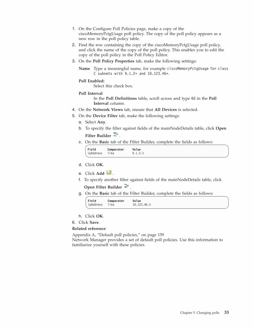
1. On the Configure Poll Policies page, make a copy of theciscoMemoryPctgUsage poll policy. The copy of the poll policy appears as anew row in the poll policy table.
2. Find the row containing the copy of the ciscoMemoryPctgUsage poll policy,and click the name of the copy of the poll policy. This enables you to edit thecopy of the poll policy in the Poll Policy Editor.
3. On the Poll Policy Properties tab, make the following settings:
Name Type a meaningful name, for example ciscoMemoryPctgUsage for classC subnets with 9.1.2* and 10.123.46*.
Poll Enabled:Select this check box.
Poll IntervalIn the Poll Definitions table, scroll across and type 60 in the PollInterval column.
4. On the Network Views tab, ensure that All Devices is selected.5. On the Device Filter tab, make the following settings:
a. Select Any.b. To specify the filter against fields of the mainNodeDetails table, click Open
Filter Builder .c. On the Basic tab of the Filter Builder, complete the fields as follows:
Field Comparator ValueipAddress like 9.1.2.%
d. Click OK.
e. Click Add .f. To specify another filter against fields of the mainNodeDetails table, click
Open Filter Builder .g. On the Basic tab of the Filter Builder, complete the fields as follows:
Field Comparator ValueipAddress like 10.123.46.%
h. Click OK.6. Click Save.Related reference:Appendix A, “Default poll policies,” on page 159Network Manager provides a set of default poll policies. Use this information tofamiliarize yourself with these policies.
Chapter 5. Changing polls 33
Changing poll definitionsChange existing poll definitions to customize them for your polling requirements.You change poll definitions in the Poll Definition Editor; the steps you follow differdepending on the poll definition type.
Before you create or change a poll definition, view an existing poll definition todetermine whether you can use it as a template to create a new poll definition.Related tasks:Chapter 4, “Creating new poll definitions,” on page 21Use the Poll Definition Editor to guide you through the steps of creating a newpoll definition.Related reference:Appendix A, “Default poll policies,” on page 159Network Manager provides a set of default poll policies. Use this information tofamiliarize yourself with these policies.
Changing basic threshold poll definitionsUse the Poll Definition Editor to change basic threshold poll definitions.
You can change some of the general properties of the poll definition and theproperties that are associated with the poll definition type. However, you cannotchange the poll definition type.
To change a basic threshold poll definition:1. Click Administration > Network > Network Polling.2. Click the required poll definition. The poll definition must have the poll
definition type Basic Threshold.3. In the Poll Definition Editor, under the General tab, complete the General
Properties fields as follows:
Name Specify a unique name for the poll definition. Only alphanumericcharacters, spaces and underscores are allowed.
Type This field is disabled. The Polling engine, ncp_poller, automaticallypopulates this field once this poll definition is included as part of anenabled poll policy. The value assigned to the event ID is POLL-pollde
Event IDThis field is disabled. The Polling engine, ncp_poller, automaticallypopulates this field once this poll definition is included as part of anenabled policy. The Event ID field is populated as follows:v If this is a new poll definition, then the Event ID field is populated
with the value POLL-polldef, where polldef is the name of thecurrent poll definition.
v If you created a poll definition by copying an existing poll definition,then the Event ID contains the same value as the copied polldefinition.
Note: Some of the older default polls have Event ID fields that do notuse the POLL-polldef naming convention.
Event SeveritySpecify a valid number for the severity. The severity level mustcorrespond to a valid severity level as defined in IBM Tivoli
34 IBM Tivoli Network Manager IP Edition: Event Management Guide
Netcool/OMNIbus. For a listing of available severity levels, refer to theIBM Tivoli Network Manager IP Edition Network Troubleshooting Guide
DescriptionType a short description of the poll definition.
Data LabelClick the data label list and select one of the data labels from the list.By default the data label takes the same name as the current polldefinition. To define a new data label, select <Add New Data Label>. Thefield to the right of the list becomes active. Type the name of the newdata label in this field.
4. Click the Classes tab. In the Classes tree, select the check boxes of the requiredclasses.Attention: If you leave all classes unchecked, then the system polls all devicesthat match the scope defined in the poll policy that uses this poll definition.
5. Optional: Click the Interface Filter tab and build the filter against the requiredfields. The Table field is prepopulated with the interfaces table.
6. Click the Poll Data tab and specify the required formula:v To specify a MIB Object Identifier (OID), select Single OID. Specify the
current or delta value of the required MIB variable and type the variable intothe next field.
v To specify a complex expression, select Expression and type the formula intothe field.
To select variables directly from the MIB tree, click Add MIB Object . Fromthe MIB tree, you can specify the current or previous values of the selected MIBvariable, or resolve the current value of the variable to the SNMP index.
7. Click the Threshold tab and specify the formulas for triggering events andclearing events. The MIB OID or expression that you specified on the Poll Datatab is written automatically into the formulas.a. In the Trigger Threshold area, select a comparator from the list and type
the value against which to filter the MIB OID.b. In the Description field, type a meaningful description of the trigger
formula. Add the MIB variable to the description in parentheses. Thedescription is displayed in the AEL when and event is raised. For example:CPU usage high (avgBusy5=)
c. To insert the underlying eval statement into the description, position the
cursor before the closing parenthesis, click Add MIB Object , andnavigate to the specified variable. Specify whether the current or previousvalue of the variable is evaluated, or whether the value is resolved to theSNMP index, and click OK. The statement is inserted, for example:CPU usage high (avgBusy5=eval(text,"&SNMP.VALUE.sysName"))
d. Repeat steps 7a to 7c for the Clear Threshold area.8. Click Save.
Chapter 5. Changing polls 35
Related concepts:“Multibyte data in poll definitions” on page 10If you are running Network Manager in a domain that uses multibyte characterssuch as Simplified Chinese, then you must ensure that Network Manager isconfigured to handle multibyte characters before you configure basic or genericthreshold poll definitions.“Poll policy scope” on page 2The poll policy scope defines the devices or device interfaces to be polled.Related reference:“Example basic threshold expression” on page 42Use this example basic threshold expression to understand how to composecomplex basic threshold expressions.Appendix D, “Syntax for poll definition expressions,” on page 175Use this information to understand how to build complex threshold expressions touse in basic and generic threshold poll definitions.
Changing generic threshold poll definitionsUse the Poll Definition Editor to change generic threshold poll definitions.
You can change some of the general properties of the poll definition and theproperties that are associated with the poll definition type. However, you cannotchange the poll definition type.
To change a generic threshold poll definition:1. Click Administration > Network > Network Polling.2. Click the required poll definition. The poll definition must have the poll
definition type Generic Threshold.3. In the Poll Definition Editor, under the General tab, complete the General
Properties fields as follows:
Name Specify a unique name for the poll definition. Only alphanumericcharacters, spaces and underscores are allowed.
Type This field is disabled. The Polling engine, ncp_poller, automaticallypopulates this field once this poll definition is included as part of anenabled poll policy. The value assigned to the event ID is POLL-pollde
Event IDThis field is disabled. The Polling engine, ncp_poller, automaticallypopulates this field once this poll definition is included as part of anenabled policy. The Event ID field is populated as follows:v If this is a new poll definition, then the Event ID field is populated
with the value POLL-polldef, where polldef is the name of thecurrent poll definition.
v If you created a poll definition by copying an existing polldefinition, then the Event ID contains the same value as the copiedpoll definition.
Note: Some of the older default polls have Event ID fields that do notuse the POLL-polldef naming convention.
Event SeveritySpecify a valid number for the severity. The severity level mustcorrespond to a valid severity level as defined in IBM Tivoli
36 IBM Tivoli Network Manager IP Edition: Event Management Guide
Netcool/OMNIbus. For a listing of available severity levels, refer tothe IBM Tivoli Network Manager IP Edition Network TroubleshootingGuide
DescriptionType a short description of the poll definition.
4. Click the Classes tab. In the Classes tree, select the check boxes of therequired classes.Attention: If you leave all classes unchecked, then the system polls alldevices that match the scope defined in the poll policy that uses this polldefinition.
5. Optional: Click the Interface Filter tab and build the filter against the requiredfields. The Table field is prepopulated with the interfaces table.
6. Click the Trigger Threshold tab. Build the formula that specifies the thresholdby using one of the following methods:v In the Basic area, use the fields and options to build a formula. To select
values from the MIB tree, click Open MIB Tree .v In the Advanced area, type the required eval statement in Object Query
Language (OQL).7. Specify the message that is displayed in the AEL for the generated event:
a. In the Event description field, type the message.
b. To insert the MIB variables in the field, click Open MIB Tree . Set themessage to include either the current or previous SNMP value, or theSNMP index, and click OK.
8. Required: Click the Clear Threshold tab. Every generic threshold polldefinition requires a clear threshold. Build the formula that specifies thethreshold by using one of the following methods:v In the Basic area, use the fields and options to build a formula. To select
values from the MIB tree, click Open MIB Tree .v In the Advanced area, type the required eval statement in Object Query
Language (OQL).
Tip: If you want the threshold to be cleared manually, create a clear thresholdthat will not be reached.
9. Specify the message that is displayed in the AEL for the generated event:a. In the Event description field, type the message.
b. To insert the MIB variables in the field, click Open MIB Tree . Set themessage to include either the current or previous SNMP value, or theSNMP index, and click OK.
10. Click Save, then click OK.
Chapter 5. Changing polls 37
Related concepts:“Multibyte data in poll definitions” on page 10If you are running Network Manager in a domain that uses multibyte characterssuch as Simplified Chinese, then you must ensure that Network Manager isconfigured to handle multibyte characters before you configure basic or genericthreshold poll definitions.“Poll policy scope” on page 2The poll policy scope defines the devices or device interfaces to be polled.Related reference:Appendix A, “Default poll policies,” on page 159Network Manager provides a set of default poll policies. Use this information tofamiliarize yourself with these policies.“Example generic threshold expression” on page 43Use this example generic threshold expression to understand how to composecomplex generic threshold expressions.Appendix D, “Syntax for poll definition expressions,” on page 175Use this information to understand how to build complex threshold expressions touse in basic and generic threshold poll definitions.
Changing chassis and interface ping poll definitionsUse the Poll Definition Editor to change chassis and interface ping poll definitiontypes.
You can change some of the general properties of the poll definition and theproperties that are associated with the poll definition type. However, you cannotchange the poll definition type.
To change a chassis or interface ping poll definition:1. Click Administration > Network > Network Polling.2. Click the required poll definition. The poll definition must have the poll
definition type Chassis Ping or Interface Ping.3. In the Poll Definition Editor, under the General tab, complete the General
Properties fields as follows:
Name Specify a unique name for the poll definition. Only alphanumericcharacters, spaces and underscores are allowed.
Type This field is disabled. The Polling engine, ncp_poller, automaticallypopulates this field once this poll definition is included as part of anenabled poll policy. The value assigned to the event ID is POLL-pollde
Event IDThis field is disabled. The Polling engine, ncp_poller, automaticallypopulates this field once this poll definition is included as part of anenabled policy. The Event ID field is populated as follows:v If this is a new poll definition, then the Event ID field is populated
with the value POLL-polldef, where polldef is the name of thecurrent poll definition.
v If you created a poll definition by copying an existing poll definition,then the Event ID contains the same value as the copied polldefinition.
Note: Some of the older default polls have Event ID fields that do notuse the POLL-polldef naming convention.
38 IBM Tivoli Network Manager IP Edition: Event Management Guide
Event SeveritySpecify a valid number for the severity. The severity level mustcorrespond to a valid severity level as defined in IBM TivoliNetcool/OMNIbus. For a listing of available severity levels, refer to theIBM Tivoli Network Manager IP Edition Network Troubleshooting Guide
DescriptionType a short description of the poll definition.
4. Click the Classes tab. In the Classes tree, select the check boxes of the requiredclasses.Attention: If you leave all classes unchecked, then the system polls all devicesthat match the scope defined in the poll policy that uses this poll definition.
5. Optional: Click the Interface Filter tab and build the filter against the requiredfields. The Table field is prepopulated with the interfaces table.
6. Click the Ping tab and complete the Ping Properties fields as follows:
TimeoutSpecify, in milliseconds, how long the polling process should wait for aresponse from the target device before sending a new ping packet.
RetriesSpecify how many times the polling process should attempt to ping thetarget device before giving up. When Packet Loss metric collection isenabled, the polling process sends this number of ping packetsregardless of whether a response is received.
Collect Ping Metrics
Response TimeCheck the box to collect the time taken by devices to respondto a ping request.
Packet LossCheck the box to collect data about lost packets.
Payload SizeSelect the size of the ICMP packet to be used for the ping request.Select the default (32 bytes) or choose a custom size. This settingoverrides the value of IcmpData in the NcPollerSchema.cfgconfiguration file.
CAUTION:Using a size smaller than 32 bytes may result in packets beingdropped.
7. Click Save, then click OK.Related concepts:“Poll policy scope” on page 2The poll policy scope defines the devices or device interfaces to be polled.
Chapter 5. Changing polls 39
Changing remote ping and link state poll definitionsUse the Poll Definition Editor to change the following poll definition types: Ciscoremote ping, Juniper remote ping, and SNMP link state.
You can change some of the general properties of the poll definition and theproperties that are associated with the poll definition type. However, you cannotchange the poll definition type.
To change a remote ping poll definition or an SNMP link state poll definition:1. Click Administration > Network > Network Polling.2. Click the required poll definition. The poll definition must have one of the
following poll definition types:v Cisco remote pingv Juniper remote pingv SNMP link state
3. In the Poll Definition Editor, under the General tab, complete the GeneralProperties fields as follows:
Name Specify a unique name for the poll definition. Only alphanumericcharacters, spaces and underscores are allowed.
Type This field is disabled. The Polling engine, ncp_poller, automaticallypopulates this field once this poll definition is included as part of anenabled poll policy. The value assigned to the event ID is POLL-pollde
Event IDThis field is disabled. The Polling engine, ncp_poller, automaticallypopulates this field once this poll definition is included as part of anenabled policy. The Event ID field is populated as follows:v If this is a new poll definition, then the Event ID field is populated
with the value POLL-polldef, where polldef is the name of thecurrent poll definition.
v If you created a poll definition by copying an existing poll definition,then the Event ID contains the same value as the copied polldefinition.
Note: Some of the older default polls have Event ID fields that do notuse the POLL-polldef naming convention.
Event SeveritySpecify a valid number for the severity. The severity level mustcorrespond to a valid severity level as defined in IBM TivoliNetcool/OMNIbus. For a listing of available severity levels, refer to theIBM Tivoli Network Manager IP Edition Network Troubleshooting Guide
DescriptionType a short description of the poll definition.
4. Click the Classes tab. In the Classes tree, select the check boxes of the requiredclasses.Attention: If you leave all classes unchecked, then the system polls all devicesthat match the scope defined in the poll policy that uses this poll definition.
5. Optional: Click the Interface Filter tab and build the filter against the requiredfields. The Table field is prepopulated with the interfaces table.
6. Click Save, then click OK.
40 IBM Tivoli Network Manager IP Edition: Event Management Guide
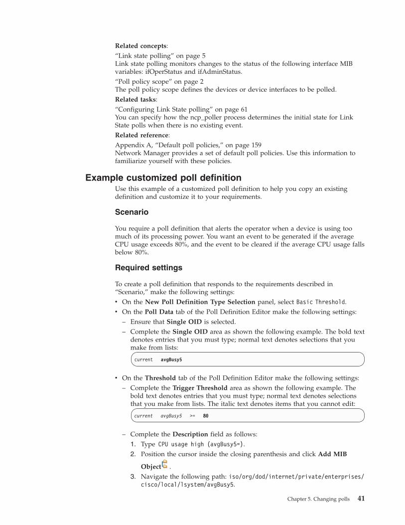
Related concepts:“Link state polling” on page 5Link state polling monitors changes to the status of the following interface MIBvariables: ifOperStatus and ifAdminStatus.“Poll policy scope” on page 2The poll policy scope defines the devices or device interfaces to be polled.Related tasks:“Configuring Link State polling” on page 61You can specify how the ncp_poller process determines the initial state for LinkState polls when there is no existing event.Related reference:Appendix A, “Default poll policies,” on page 159Network Manager provides a set of default poll policies. Use this information tofamiliarize yourself with these policies.
Example customized poll definitionUse this example of a customized poll definition to help you copy an existingdefinition and customize it to your requirements.
Scenario
You require a poll definition that alerts the operator when a device is using toomuch of its processing power. You want an event to be generated if the averageCPU usage exceeds 80%, and the event to be cleared if the average CPU usage fallsbelow 80%.
Required settings
To create a poll definition that responds to the requirements described in“Scenario,” make the following settings:v On the New Poll Definition Type Selection panel, select Basic Threshold.v On the Poll Data tab of the Poll Definition Editor make the following settings:
– Ensure that Single OID is selected.– Complete the Single OID area as shown the following example. The bold text
denotes entries that you must type; normal text denotes selections that youmake from lists:
current avgBusy5
v On the Threshold tab of the Poll Definition Editor make the following settings:– Complete the Trigger Threshold area as shown the following example. The
bold text denotes entries that you must type; normal text denotes selectionsthat you make from lists. The italic text denotes items that you cannot edit:
current avgBusy5 >= 80
– Complete the Description field as follows:1. Type CPU usage high (avgBusy5=).2. Position the cursor inside the closing parenthesis and click Add MIB
Object .3. Navigate the following path: iso/org/dod/internet/private/enterprises/
cisco/local/lsystem/avgBusy5.
Chapter 5. Changing polls 41
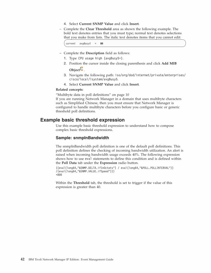
4. Select Current SNMP Value and click Insert.– Complete the Clear Threshold area as shown the following example. The
bold text denotes entries that you must type; normal text denotes selectionsthat you make from lists. The italic text denotes items that you cannot edit:
current avgBusy5 < 80
– Complete the Description field as follows:1. Type CPU usage high (avgBusy5=).2. Position the cursor inside the closing parenthesis and click Add MIB
Object .3. Navigate the following path: iso/org/dod/internet/private/enterprises/
cisco/local/lsystem/avgBusy5.4. Select Current SNMP Value and click Insert.
Related concepts:“Multibyte data in poll definitions” on page 10If you are running Network Manager in a domain that uses multibyte characterssuch as Simplified Chinese, then you must ensure that Network Manager isconfigured to handle multibyte characters before you configure basic or genericthreshold poll definitions.
Example basic threshold expressionUse this example basic threshold expression to understand how to composecomplex basic threshold expressions.
Sample: snmpInBandwidth
The snmpInBandwidth poll definition is one of the default poll definitions. Thispoll definition defines the checking of incoming bandwidth utilization. An alert israised when incoming bandwidth usage exceeds 40%. The following expressionshows how to use eval statements to define this condition and is defined withinthe Poll Data tab under the Expression radio button.((eval(long64,"&SNMP.DELTA.ifInOctets") / eval(long64,"&POLL.POLLINTERVAL"))/(eval(long64,"&SNMP.VALUE.ifSpeed")))*800
Within the Threshold tab, the threshold is set to trigger if the value of thisexpression is greater than 40.
42 IBM Tivoli Network Manager IP Edition: Event Management Guide
Related concepts:“Multibyte data in poll definitions” on page 10If you are running Network Manager in a domain that uses multibyte characterssuch as Simplified Chinese, then you must ensure that Network Manager isconfigured to handle multibyte characters before you configure basic or genericthreshold poll definitions.Related tasks:“Changing basic threshold poll definitions” on page 34Use the Poll Definition Editor to change basic threshold poll definitions.“Creating basic threshold poll definitions” on page 21Create a basic threshold poll definition to run simple formulas against MIBvariables, or to create threshold polls with interface-level filtering.Related reference:Appendix D, “Syntax for poll definition expressions,” on page 175Use this information to understand how to build complex threshold expressions touse in basic and generic threshold poll definitions.
Example generic threshold expressionUse this example generic threshold expression to understand how to composecomplex generic threshold expressions.
Sample: memoryPoll
The memoryPoll poll definition is one of the default poll definitions. This polldefinition defines the checking of memory-pool usage for Cisco devices. An alert israised when the memory pool usage exceeds 80%. The following expression showshow to use eval statements to define this condition and is defined within theTrigger Threshold tab under the Advanced radio button.((eval(int,"&SNMP.VALUE.ciscoMemoryPoolValid") = 1)AND((eval(long64,"&SNMP.VALUE.ciscoMemoryPoolUsed")/(eval(long64,"&SNMP.VALUE.ciscoMemoryPoolFree") +eval(long64,"&SNMP.VALUE.ciscoMemoryPoolUsed")))*100> 80))
Related concepts:“Multibyte data in poll definitions” on page 10If you are running Network Manager in a domain that uses multibyte characterssuch as Simplified Chinese, then you must ensure that Network Manager isconfigured to handle multibyte characters before you configure basic or genericthreshold poll definitions.Related tasks:“Changing generic threshold poll definitions” on page 36Use the Poll Definition Editor to change generic threshold poll definitions.“Creating generic threshold poll definitions” on page 23Use the Poll Definition Editor to create new generic threshold poll definitions.Related reference:Appendix D, “Syntax for poll definition expressions,” on page 175Use this information to understand how to build complex threshold expressions touse in basic and generic threshold poll definitions.
Chapter 5. Changing polls 43

44 IBM Tivoli Network Manager IP Edition: Event Management Guide

Chapter 6. Deleting poll policies
Delete poll policies when they are no longer required.
To delete a poll policy:1. Click Administration > Network > Network Polling.2. In the Select column, select the required poll policies.
3. Click Delete .4. Click OK to confirm the deletion.
The selected poll policies are deleted.
© Copyright IBM Corp. 2006, 2013 45

46 IBM Tivoli Network Manager IP Edition: Event Management Guide

Chapter 7. Deleting poll definitions
Delete poll definitions when they are no longer required.
To delete a poll definition:1. Click Administration > Network > Network Polling.2. In the Select column, select the required poll definitions.
3. Click Delete .4. Click OK to confirm the deletion.
The selected poll definitions are deleted.
© Copyright IBM Corp. 2006, 2013 47

48 IBM Tivoli Network Manager IP Edition: Event Management Guide
Chapter 8. Managing adaptive polling
Adaptive polls dynamically react to events on the network. You can createadaptive polls that manage a wide range of network problem scenarios.Related concepts:“Adaptive polling plug-in” on page 107Use this information to understand plug-in prerequisites, how the adaptive pollingplug-in populates fields in the activeEvent table, as well as configuration detailsassociated with the plug-in. The activeEvent table is in the NCMONITOR schema.Related reference:“Plugin descriptions” on page 106Use this information to understand what each Event Gateway plugin does.
Adaptive polling scenariosNetwork Manager provides default adaptive polls to automatically handle keynetwork problem scenarios. Use these default adaptive polls to understand how tocreate your own adaptive polls.
Rapid confirmation that device is really downUse the adaptive polling described in this scenario to determine as quickly aspossible when a device is really down. You can activate this adaptive polling byenabling the ConfirmDeviceDown poll policy.
Rationale
The standard Default Chassis Ping poll policy polls all chassis devices in thecurrent network domain every two minutes. For various reasons healthy devicessometimes fail to respond to this poll policy, generating misleading NmosPingFailevents in the Active Event List (AEL). These events are not cleared until asuccessful ping response at least two minutes later. During that time thesemisleading events might cause network operators to take unnecessary action.
The adaptive polling described in this scenario avoids the risk of unnecessarynetwork operations activity by accelerating pinging of all devices on which anNmosPingFail event is first raised. These devices are pinged by a separate pollpolicy every 10 seconds for three minutes, with the intention of clearing the eventas soon as the device responds. Those devices that still exhibit an NmosPingFailevent after three minutes of accelerated pinging are considered to be really down,and are no longer pinged. The network operator can take action on these devices,or automations can be written to take relevant action, with the confidence that theevents are actionable.
Note: The three minutes are enforced by specifying as policy scope devices withan NmosPingFail event and a Tally value of less than 18. The Tally value iscalculated by assuming that a faulty device will fail to respond to all acceleratedpolls. Each minute there are six accelerated ping polls, so in a three minute periodthere will be 18, and the Tally value of those devices that are still not respondingwill reach 18.
© Copyright IBM Corp. 2006, 2013 49
The accelerated pinging values are fully configurable. For example, you can specifya 20 second accelerated ping polling interval (instead of a 10 second interval) tolighten the load on the network. You could also continue accelerated polling forlonger than three minutes (by increasing the Tally value) if you require a longertime to verify that devices are really down.
Chained poll policies
The adaptive poll described in this scenario is made up of the following chainedpoll policies:
Default Chassis PingThis poll policy pings all devices in the network every two minutes. It isenabled by default.
ConfirmDeviceDownThis poll policy provides accelerated pinging at 10 second intervals ofdevices that fail to respond to the Default Chassis Ping poll policy. TheConfirmDeviceDown policy must be assigned to a network view.
Important: The ConfirmDeviceDown poll policy is disabled by default.You must enable this poll policy in order to activate the adaptive pollingdescribed in this scenario.
Scenario walkthrough
The following section walks you through this adaptive poll.1. The Default Chassis Ping poll policy polls all chassis device in the current
network domain. You can modify the scope of this policy by modifying theassociated network views and device filter.
2. An NmosPingFail event is generated for all devices that do not respond to theDefault Chassis Ping policy.
3. Devices that have an associated NmosPingFail event are automatically added tothe Initial Ping Fail Events network view. The Initial Ping Fail Events networkview is a Filtered network view that is defined as follows:
EventId = NmosPingFailTally < 18
The Initial Ping Fail Events network view can be found in the Network Views,in the Network View tree, in the Monitoring Views > Initial Ping Fail Eventsnode. For more information on the nodes in the network view tree, see the IBMTivoli Network Manager IP Edition Network Troubleshooting Guide.You can change the duration of accelerated polling by modifying the Tally <18 filter clause. For example, if you want to increase the duration of acceleratedpolling to five minutes, then change this clause to Tally < 30. This value isdetermined by the following calculation based on a 10 second polling interval:each minute there are six accelerated ping polls, so in a five minute periodthere will be 30. For more information on changing event-filtered networkviews, see the IBM Tivoli Network Manager IP Edition Network Visualization SetupGuide.
4. The ConfirmDeviceDown poll policy polls all devices within the Initial PingFail Events network view every 10 seconds. Each time the device does notrespond, another NmosPingFail is received for the device, and theNmosPingFail Tally value for the device is incremented.
50 IBM Tivoli Network Manager IP Edition: Event Management Guide
Important: By default you have to take the following actions in order toactivate the adaptive polling described in this scenario:v The ConfirmDeviceDown poll policy is disabled by default. You must enable
this poll policy.v The ConfirmDeviceDown poll policy has no scope by default. You must
assign the Initial Ping Fail Events network view as the scope of theConfirmDeviceDown poll policy.
You can change the frequency of accelerated ping polling by editing theConfirmDeviceDown poll policy and modifying the interval in secondsbetween poll operations. For example, if you want to decrease the pollingfrequency to 20 second polling intervals (three polls per minute rather thansix), then open the ConfirmDeviceDown poll policy in the Poll Policy Editorand set the Poll Interval value to 20.
Note: Changing the poll policy interval changes the Tally value for the sameaccelerated polling duration. For example, if you change the Poll Interval valueto 20 this decreases the frequency of accelerated ping polling to 3 polls perminute. In this case the associated Tally value for a three minutes of acceleratedpolling is 9. This value is determined by the following calculation based on a20 second polling interval: each minute there are three accelerated ping polls,so in a three minute period there will be 9.
5. Accelerated polling of devices can conclude in one of the following ways:
Healthy deviceDuring the three-minute accelerated polling period a successful pingresponse is received for a device. The NmosPingFail event for thatdevice is cleared and will subsequently be deleted from the ActiveEvent List (AEL). The device is automatically removed from the InitialPing Fail Events network view, and therefore is no longer subject toaccelerated polling.
Faulty deviceThe device continues to be ping polled until the end of thethree-minute period. The Tally value for the event on that devicereaches 18 and the device is automatically removed from the InitialPing Fail Events network view, and therefore is no longer subject toaccelerated polling. The Active Event List (AEL) now contains anactionable event, that is, an NmosPingFail event with a tally of 18 orgreater.
Chapter 8. Managing adaptive polling 51
Related tasks:Chapter 2, “Enabling and disabling polls,” on page 11To activate Network Manager polling, you must enable the poll policies. If anetwork entity is off the network, disable the poll policy that polls that entity.“Changing poll policies” on page 29Use the Poll Policy Editor to change the settings of existing poll policies.“Creating adaptive polls” on page 55Create adaptive polls to enable the system to dynamically react to events on thenetwork.Related reference:Appendix A, “Default poll policies,” on page 159Network Manager provides a set of default poll policies. Use this information tofamiliarize yourself with these policies.Appendix B, “Default poll definitions,” on page 165Network Manager provides a number of default poll definitions that fulfil the mostcommon polling requirements.
Rapid confirmation of a threshold violationUse the adaptive polling defined in this scenario to use slow SNMP polling mostof the time to create minimum impact on your network devices, and acceleratepolling when a threshold has actually been breached. You can activate thisadaptive polling by enabling the ConfirmHighDiscardRate poll policy.
Rationale
The standard HighDiscardRate poll policy performs an SNMP threshold poll on allrouters in the current network domain every 30 minutes to determine if thepercentage packet discard rate on any of the router interfaces exceeds 5%. If thepoll policy detects that any one interface on a router has exceeded the threshold,then the poll generates a POLL-HighDiscardRate event for the router. Healthyrouter interfaces might occasionally be busy and need to drop packets, causingthem to breach the 5% threshold during any one 30 minute interval, generatingmisleading HighDiscardRate events in the Active Event List (AEL). These eventsare not cleared until a successful POLL-HighDiscardRate poll policy responseoccurs at least thirty minutes later. During that time these misleading events mightcause network operators to take unnecessary action.
The adaptive polling described in this scenario avoids the risk of unnecessarynetwork operations activity by accelerating SNMP polling of all devices on which aPOLL-HighDiscardRate event is first raised. These devices are polled by a separateSNMP poll policy every five minutes, with the intention of clearing the event assoon as all interfaces on the device respond with a percentage packet discard ratethat falls within the 5% threshold. Those devices that continue to exhibit thePOLL-HighDiscardRate event are confirmed as having one or more faultyinterfaces. The network operator can take action on these devices, or automationscan be written to take relevant action, with the confidence that the events areactionable.
The accelerated polling values are fully configurable. For example, you can specifya 10 minute accelerated SNMP polling interval (instead of a 5 minute interval) tolighten the load on the network.
52 IBM Tivoli Network Manager IP Edition: Event Management Guide
Chained poll policies
The adaptive poll described in this scenario is made up of the following chainedpoll policies:
HighDiscardRateThis poll policy determines whether an interface on a device is droppingmore than a minimum percentage of the total packets that it is processing.The policy polls for this information every 30 minutes.
ConfirmHighDiscardRateThis poll policy provides accelerated SNMP polling at five minutesintervals of devices that have at least one interface that breached the 5%packet discard rate threshold. The ConfirmHighDiscardRate policy scopemust be assigned to a network view.
Important: The ConfirmHighDiscardRate poll policy is disabled by default.You must enable this poll policy in order to activate the adaptive pollingdescribed in this scenario.
Scenario walkthrough
The following section walks you through this adaptive poll.1. The HighDiscardRate SNMP poll policy performs an SNMP threshold poll on
all routers in the current network domain every 30 minutes. You can modifythe scope of this policy by modifying the associated network views and devicefilter.
2. A POLL-HighDiscardRate event is generated for all devices that have at leastone interface that breached the 5% packet discard rate threshold.
3. Devices that have an associated POLL-HighDiscardRate event are automaticallyadded to the Devices that have at least one interface event for HighDiscardRatenetwork view. This network view is a Filtered network view that is defined asfollows:
EventId = POLL-HighDiscardRate
The Devices that have at least one interface event for HighDiscardRate networkview can be found in the Network Views, in the Network View tree, in theMonitoring Views > Devices that have at least one interface event forHighDiscardRate node. For more information on the nodes in the networkview tree, see the IBM Tivoli Network Manager IP Edition Network TroubleshootingGuide.
4. The ConfirmHighDiscardRate poll policy polls all devices within the Devicesthat have at least one interface event for HighDiscardRate network view everyfive minutes.
Important: By default you have to take the following actions in order toactivate the adaptive polling described in this scenario:v The ConfirmHighDiscardRate poll policy is disabled by default. You must
enable this poll policy.v The ConfirmHighDiscardRate poll policy has no scope by default. You must
assign the Devices that have at least one interface event for HighDiscardRatenetwork view as the scope of the ConfirmHighDiscardRate poll policy.
Chapter 8. Managing adaptive polling 53
Important: The ConfirmHighDiscardRate poll policy is disabled by default.You must enable this poll policy in order to activate the adaptive pollingdescribed in this scenario.You can change the frequency of accelerated SNMP threshold polling by editingthe ConfirmHighDiscardRate poll policy and modifying the interval in secondsbetween poll operations. For example, if you want to decrease the pollingfrequency to 10 minute polling intervals, then open theConfirmHighDiscardRate poll policy in the Poll Policy Editor and set the PollInterval value to 600.
5. Accelerated SNMP threshold polling of devices can conclude in one of thefollowing ways:
Healthy deviceAll interfaces on the device respond to the accelerated poll with apercentage packet discard rate that falls within the 5% threshold. ThePOLL-HighDiscardRate event for that device is cleared and willsubsequently be deleted from the Active Event List (AEL). The deviceis automatically removed from the Devices that have at least oneinterface event for HighDiscardRate network view, and therefore is nolonger subject to accelerated polling.
Faulty deviceAt least one interface on the device continues to respond to theaccelerated SNMP poll with a breach of the 5% packet discard rate. ThePOLL-HighDiscardRate event remains in the Active Event List (AEL)with a continually increasing Tally value. The Active Event List (AEL)now contains an actionable POLL-HighDiscardRate event.
Related tasks:Chapter 2, “Enabling and disabling polls,” on page 11To activate Network Manager polling, you must enable the poll policies. If anetwork entity is off the network, disable the poll policy that polls that entity.“Changing poll policies” on page 29Use the Poll Policy Editor to change the settings of existing poll policies.“Creating adaptive polls” on page 55Create adaptive polls to enable the system to dynamically react to events on thenetwork.Related reference:Appendix A, “Default poll policies,” on page 159Network Manager provides a set of default poll policies. Use this information tofamiliarize yourself with these policies.Appendix B, “Default poll definitions,” on page 165Network Manager provides a number of default poll definitions that fulfil the mostcommon polling requirements.
54 IBM Tivoli Network Manager IP Edition: Event Management Guide
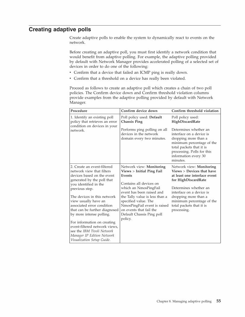
Creating adaptive pollsCreate adaptive polls to enable the system to dynamically react to events on thenetwork.
Before creating an adaptive poll, you must first identify a network condition thatwould benefit from adaptive polling. For example, the adaptive polling providedby default with Network Manager provides accelerated polling of a selected set ofdevices in order to do one of the following:v Confirm that a device that failed an ICMP ping is really down.v Confirm that a threshold on a device has really been violated.
Proceed as follows to create an adaptive poll which creates a chain of two pollpolicies. The Confirm device down and Confirm threshold violation columnsprovide examples from the adaptive polling provided by default with NetworkManager.
Procedure Confirm device down Confirm threshold violation
1. Identify an existing pollpolicy that retrieves an errorcondition on devices in yournetwork.
Poll policy used: DefaultChassis Ping
Performs ping polling on alldevices in the networkdomain every two minutes.
Poll policy used:HighDiscardRate
Determines whether aninterface on a device isdropping more than aminimum percentage of thetotal packets that it isprocessing. Polls for thisinformation every 30minutes.
2. Create an event-filterednetwork view that filtersdevices based on the eventgenerated by the poll thatyou identified in theprevious step.
The devices in this networkview usually have anassociated error conditionthat can be further diagnosedby more intense polling.
For information on creatingevent-filtered network views,see the IBM Tivoli NetworkManager IP Edition NetworkVisualization Setup Guide.
Network view: MonitoringViews > Initial Ping FailEvents
Contains all devices onwhich an NmosPingFailevent has been raised andthe Tally value is less than aspecified value. TheNmosPingFail event is raisedon events that fail theDefault Chassis Ping pollpolicy.
Network view: MonitoringViews > Devices that haveat least one interface eventfor HighDiscardRate
Determines whether aninterface on a device isdropping more than aminimum percentage of thetotal packets that it isprocessing.
Chapter 8. Managing adaptive polling 55
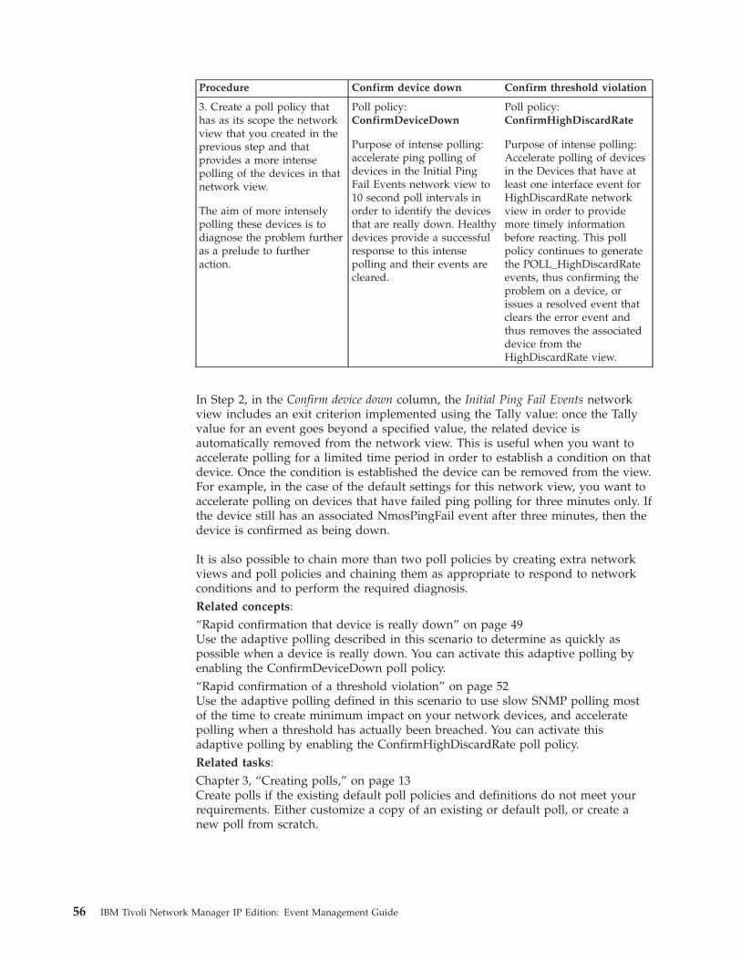
Procedure Confirm device down Confirm threshold violation
3. Create a poll policy thathas as its scope the networkview that you created in theprevious step and thatprovides a more intensepolling of the devices in thatnetwork view.
The aim of more intenselypolling these devices is todiagnose the problem furtheras a prelude to furtheraction.
Poll policy:ConfirmDeviceDown
Purpose of intense polling:accelerate ping polling ofdevices in the Initial PingFail Events network view to10 second poll intervals inorder to identify the devicesthat are really down. Healthydevices provide a successfulresponse to this intensepolling and their events arecleared.
Poll policy:ConfirmHighDiscardRate
Purpose of intense polling:Accelerate polling of devicesin the Devices that have atleast one interface event forHighDiscardRate networkview in order to providemore timely informationbefore reacting. This pollpolicy continues to generatethe POLL_HighDiscardRateevents, thus confirming theproblem on a device, orissues a resolved event thatclears the error event andthus removes the associateddevice from theHighDiscardRate view.
In Step 2, in the Confirm device down column, the Initial Ping Fail Events networkview includes an exit criterion implemented using the Tally value: once the Tallyvalue for an event goes beyond a specified value, the related device isautomatically removed from the network view. This is useful when you want toaccelerate polling for a limited time period in order to establish a condition on thatdevice. Once the condition is established the device can be removed from the view.For example, in the case of the default settings for this network view, you want toaccelerate polling on devices that have failed ping polling for three minutes only. Ifthe device still has an associated NmosPingFail event after three minutes, then thedevice is confirmed as being down.
It is also possible to chain more than two poll policies by creating extra networkviews and poll policies and chaining them as appropriate to respond to networkconditions and to perform the required diagnosis.Related concepts:“Rapid confirmation that device is really down” on page 49Use the adaptive polling described in this scenario to determine as quickly aspossible when a device is really down. You can activate this adaptive polling byenabling the ConfirmDeviceDown poll policy.“Rapid confirmation of a threshold violation” on page 52Use the adaptive polling defined in this scenario to use slow SNMP polling mostof the time to create minimum impact on your network devices, and acceleratepolling when a threshold has actually been breached. You can activate thisadaptive polling by enabling the ConfirmHighDiscardRate poll policy.Related tasks:Chapter 3, “Creating polls,” on page 13Create polls if the existing default poll policies and definitions do not meet yourrequirements. Either customize a copy of an existing or default poll, or create anew poll from scratch.
56 IBM Tivoli Network Manager IP Edition: Event Management Guide

Chapter 9. Administering network polling
Use the command-line interface to perform a wide range of polling administrationtasks, including managing the multiple poller feature, copying network polls acrossnetwork domains, suspending network polling, enabling and disabling polls,retrieving poll status, and refreshing polls.
You can also configure the SNMP Helper to use the GetBulk operation whenSNMP v2 or v3 is used. Use of the GetBulk operation improves polling efficiency.For more information, see the IBM Tivoli Network Manager IP Edition Installation andConfiguration Guide.
Administering pollsUse the command-line interface to administer poll policies.
Retrieving poll statusUse the itnm_poller.pl script to display the status of poll policies.
The domain provided on the command-line interface (CLI) must have an entry inthe domainMgr NCIM table.
For more information on the itnm_poller.pl script, see the IBM Tivoli NetworkManager IP Edition Administration Guide.1. Change to the $NCHOME/precision/scripts/perl/scripts directory and locate
the itnm_poller.pl script.2. Run the itnm_poller.pl script program to retrieve the status of poll policies.
The following example shows how to retrieve the status of all poll policies.ncp_perl itnm_poller.pl -domain NCOMS -status all
You can also retrieve the status of only realtime or static poll polices byspecifying -status realtime or -status static.
Enabling and disabling pollsUse the itnm_poller.pl script to enable and disable individual poll policies.
The domain provided on the command-line interface (CLI) must have an entry inthe domainMgr NCIM table.
For more information on the itnm_poller.pl script, see the IBM Tivoli NetworkManager IP Edition Administration Guide.1. Change to the $NCHOME/precision/scripts/perl/scripts directory and locate
the itnm_poller.pl script.2. Run the itnm_poller.pl script program to retrieve the status of the various poll
policies, as shown in the following example.ncp_perl itnm_poller.pl -domain NCOMS -status all
In the output of the command you can see the ID for each poll policy. Make anote of the ID for the poll policy that you want to enable or disable.
© Copyright IBM Corp. 2006, 2013 57
3. Run the itnm_poller.pl script program to enable or disable individual pollpolicies, specifying the poll policy ID as a parameter. The following exampleshows how to enable a poll policy with a policy ID of 10.ncp_perl itnm_poller.pl -domain NCOMS -enable 10
The following example shows how to disable a poll policy with a policy ID of15.ncp_perl itnm_poller.pl -domain NCOMS -disable 15
Refreshing pollsUse the itnm_poller.pl script to refresh a poll policy configuration and its entitylist.
The domain provided on the command-line interface (CLI) must have an entry inthe NCIM topology database domainMgr table.
For more information on the itnm_poller.pl script, see the IBM Tivoli NetworkManager IP Edition Administration Guide.1. Change to the $NCHOME/precision/scripts/perl/scripts directory and locate
the itnm_poller.pl script.2. Run the itnm_poller.pl script program to retrieve the status of the various poll
policies, as shown in the following example.ncp_perl itnm_poller.pl -domain NCOMS -status all
In the output of the command you can see the ID for each poll policy. Make anote of the ID for the poll policy that you want to enable or disable.
3. Run the itnm_poller.pl script program to refresh a single poll policy, or of pollpolicies. The following example shows how to refresh a poll policy with apolicy ID of 10.ncp_perl itnm_poller.pl -domain NCOMS -refresh 10
The following example shows how to refresh all poll policies.ncp_perl itnm_poller.pl -domain NCOMS -refresh all
Copying polls across domainsUse the get_policies.pl program to copy your poll policies from one networkdomain to another, or between a file and a domain.
If you provide a domain name with either the -to or -from options, you must beconnected to the NCIM and NCMONITOR databases. The connections are createdbased on the settings in the DbLogins.DOMAIN.cfg file, or the DbLogins.cfg file if nodomain-specific file is found.
The domain provided on the command-line interface (CLI) must have an entry inthe domainMgr NCIM table.1. Change to the NCHOME/precision/scripts/perl/scripts directory and locate the
get_policies.pl program.2. Run the get_policies.pl program to copy poll policies. The following table
describes the possible actions and what to enter on the CLI.
58 IBM Tivoli Network Manager IP Edition: Event Management Guide
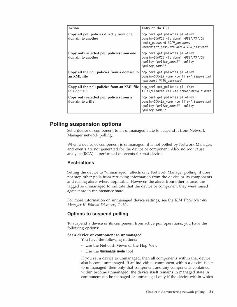
Action Entry on the CLI
Copy all poll policies directly from onedomain to another
ncp_perl get_policies.pl -fromdomain=SOURCE -to domain=DESTINATION-ncim_password NCIM_password-ncmonitor_password NCMONITOR_password
Copy only selected poll policies from onedomain to another
ncp_perl get_policies.pl -fromdomain=SOURCE -to domain=DESTINATION-policy "policy_name1" -policy"policy_name2"
Copy all the poll policies from a domain toan XML file
ncp_perl get_policies.pl -fromdomain=DOMAIN_name -to file=filename.xml-password NCIM_password
Copy all the poll policies from an XML fileto a domain
ncp_perl get_policies.pl -fromfile=filename.xml -to domain=DOMAIN_name
Copy only selected poll policies from adomain to a file
ncp_perl get_policies.pl -fromdomain=DOMAIN_name -to file=filename.xml-policy "policy_name1" -policy"policy_name2"
Polling suspension optionsSet a device or component to an unmanaged state to suspend it from NetworkManager network polling.
When a device or component is unmanaged, it is not polled by Network Manager,and events are not generated for the device or component. Also, no root causeanalysis (RCA) is performed on events for that device.
Restrictions
Setting the device to “unmanaged” affects only Network Manager polling, it doesnot stop other polls from retrieving information from the device or its componentsand raising alerts where applicable. However, the alerts from other sources aretagged as unmanaged to indicate that the device or component they were raisedagainst are in maintenance state.
For more information on unmanaged device settings, see the IBM Tivoli NetworkManager IP Edition Discovery Guide.
Options to suspend polling
To suspend a device or its component from active poll operations, you have thefollowing options:
Set a device or component to unmanagedYou have the following options:v Use the Network Views or the Hop Viewv Use the Unmanage node tool
If you set a device to unmanaged, then all components within that devicealso become unmanaged. If an individual component within a device is setto unmanaged, then only that component and any components containedwithin become unmanaged, the device itself remains in managed state. Acomponent can be managed or unmanaged only if the device within which
Chapter 9. Administering network polling 59

it resides is in managed state. Also, setting the management interfaceassociated with the chassis to unmanaged state does not suspend polls forthe whole device.
Set specific interface types to be permanently unmanagedThis means that the specified interface types are not polled by NetworkManager. Also, you can set new devices not to be polled initially afterbeing discovered and added to the topology. These settings are determinedby the TagManagedEntities.stch file and the NCIM database tables.
For more information on the Network Views and the Hop View, see the IBM TivoliNetwork Manager IP Edition Network Visualization Setup Guide. For more informationon setting devices and components to an unmanaged state, see the IBM TivoliNetwork Manager IP Edition Network Troubleshooting Guide.
Administering poll policy throttlingYou can configure how much data is transferred by the Polling engine, ncp_poller,and how often. You might want to adjust polling bandwidth to avoid networkcongestion or to reduce the impact of large numbers of polling events occurringsimultaneously.
Changing the interval for checking poll policy membership sizeYou can change the interval for checking poll policy membership size for all pollpolicies.
Before changing the interval for checking poll policy membership size, you shouldconsider the following:v A longer interval means less load on the network due to longer time between
checks.v A shorter interval means that ncp_poller is kept more up to date with changes,
especially network view membership size.1. Edit the following configuration file: $NCHOME/etc/precision/
NcPollerSchema.cfg.2. Add the following line to the end of the file:
update config.properties set PolicyUpdateInterval= update_interval;
Where: update_interval is the interval for checking poll policy membership size,in seconds. The default value is 30 seconds.
3. Restart the Polling engine, ncp_poller.
Enabling and disabling network view updates for poll policiesBy default network view updates are enabled for all poll policies. You can disablenetwork view updates if you are polling stable network views. This will avoid anyperformance issues associated with the update.1. Edit the following configuration file: $NCHOME/etc/precision/
NcPollerSchema.cfg.2. Add the following line to the end of the file:
update config.properties set UpdateNetworkViewCache = enable_or_disable_update;
Where: enable_or_disable_update is either 1 (enable) or 0 (disable ). The defaultvalue is 1 (enable).
3. Restart the Polling engine, ncp_poller.
60 IBM Tivoli Network Manager IP Edition: Event Management Guide
Speeding up ncp_poller startup by not checking SNMPcredentials
Disabling the testing of SNMP access credentials on startup of ncp_poller canimprove startup times.
If you are sure that your access credentials for the devices you want to poll areaccurate, you can configure the polling process, ncp_poller, not to check them onstartup.1. Back up and edit the file NCHOME/etc/precision/NcPollerSchema.DOMAIN.cfg
2. Locate the line that defines the value of the DiscoverInitialAccess option.3. If you want the ncp_poller process to check the SNMP credentials each time it
starts up, leave the value of DiscoverInitialAccess set to 1.4. To turn off the initial checking of SNMP access credentials, set the value of
DiscoverInitialAccess set to 0. The ncp_poller process still tests SNMPcredentials for a given device if there is a poll failure.
5. Restart the ncp_poller process.
Configuring Link State pollingYou can specify how the ncp_poller process determines the initial state for LinkState polls when there is no existing event.
The ncp_poller process can either use the first poll to determine the initial state ofLink State polls, or assume a Clear state.1. Edit the NCHOME/etc/precision/NcPollerSchema.cfg file.2. Locate the config.properties section.3. Edit the value for UseFirstPollForInitialState.
v Set to 0 to set the initial state to Clear.v Set to 1 to configure the initial state to be determined by the first poll.
Related concepts:“Link state polling” on page 5Link state polling monitors changes to the status of the following interface MIBvariables: ifOperStatus and ifAdminStatus.Related tasks:“Changing remote ping and link state poll definitions” on page 40Use the Poll Definition Editor to change the following poll definition types: Ciscoremote ping, Juniper remote ping, and SNMP link state.
Administering multiple pollersIf multiple pollers are needed to poll your network, you can set up NetworkManager to administer the multiple poller feature. You can add pollers or removepollers, or use a poller ID to associate a specific poller with a policy.
Chapter 9. Administering network polling 61

Multiple poller overviewYou can use multiple pollers to scale your polling to more devices and forperformance reasons.
The poller process has two functions: to poll network devices, and to performadministrative tasks such as data pruning and updating caches. If a single poller ispolling many devices on a regular basis, consider using multiple pollers forpolling.
You can also avoid performance issues by using a separate poller to performadministrative functions. Start only one poller with the -admin option, and do notuse this poller for polling network devices. Start the other pollers with the-noadmin option, and use these pollers for network polling. If you are usingfailover, replicate the same arrangement of pollers on the backup server.
Each poller is registered with a name that the administrator can use to associate apolicy with a poller.
Restriction: Distributing polling over multiple servers is not supported. Start allpollers on the Network Manager server.
You can monitor the polling engines using the Network Manager Health views inIBM Tivoli® Monitoring.
For additional information, see the IBM Tivoli Monitoring for Tivoli Network ManagerIP User's Guide.
Monitor Policy editor
When multiple pollers are deployed, the administrator controls which poller isused by a policy. By default, each policy uses the default poller on the NetworkManager server. The administrator can select a different poller from a list ofregistered pollers.
Real-time MIB graphing
The poller used for real-time polling is defined by the administrator.
Setting up an additional pollerSet up an additional poller on the Network Manager server if one poller is notsufficient to handle your network load.
To set up an additional poller for the monitoring system, you must register andcreate the new poller instances.
The default poller is automatically installed when you install Network Manager.Complete the following steps to register a new instance of the poller andautomatically start the poller.1. On the system where the poller will run, register the poller by entering the
following command.ncp_poller -domain domain_name -register -name poller_name
2. Edit the CtrlServices.cfg file.a. Locate the entry for the ncp_poller process.
62 IBM Tivoli Network Manager IP Edition: Event Management Guide
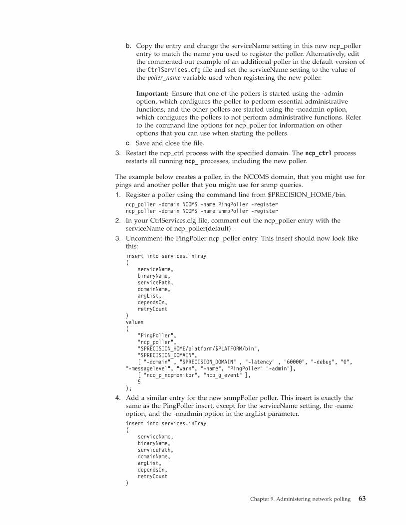
b. Copy the entry and change the serviceName setting in this new ncp_pollerentry to match the name you used to register the poller. Alternatively, editthe commented-out example of an additional poller in the default version ofthe CtrlServices.cfg file and set the serviceName setting to the value ofthe poller_name variable used when registering the new poller.
Important: Ensure that one of the pollers is started using the -adminoption, which configures the poller to perform essential administrativefunctions, and the other pollers are started using the -noadmin option,which configures the pollers to not perform administrative functions. Referto the command line options for ncp_poller for information on otheroptions that you can use when starting the pollers.
c. Save and close the file.3. Restart the ncp_ctrl process with the specified domain. The ncp_ctrl process
restarts all running ncp_ processes, including the new poller.
The example below creates a poller, in the NCOMS domain, that you might use forpings and another poller that you might use for snmp queries.1. Register a poller using the command line from $PRECISION_HOME/bin.
ncp_poller -domain NCOMS -name PingPoller -registerncp_poller -domain NCOMS -name snmpPoller -register
2. In your CtrlServices.cfg file, comment out the ncp_poller entry with theserviceName of ncp_poller(default) .
3. Uncomment the PingPoller ncp_poller entry. This insert should now look likethis:insert into services.inTray(
serviceName,binaryName,servicePath,domainName,argList,dependsOn,retryCount
)values(
"PingPoller","ncp_poller","$PRECISION_HOME/platform/$PLATFORM/bin","$PRECISION_DOMAIN",[ "-domain" , "$PRECISION_DOMAIN" , "-latency" , "60000", "-debug", "0",
"-messagelevel", "warn", "-name", "PingPoller" "-admin"],[ "nco_p_ncpmonitor", "ncp_g_event" ],5
);
4. Add a similar entry for the new snmpPoller poller. This insert is exactly thesame as the PingPoller insert, except for the serviceName setting, the -nameoption, and the -noadmin option in the argList parameter.insert into services.inTray(
serviceName,binaryName,servicePath,domainName,argList,dependsOn,retryCount
)
Chapter 9. Administering network polling 63
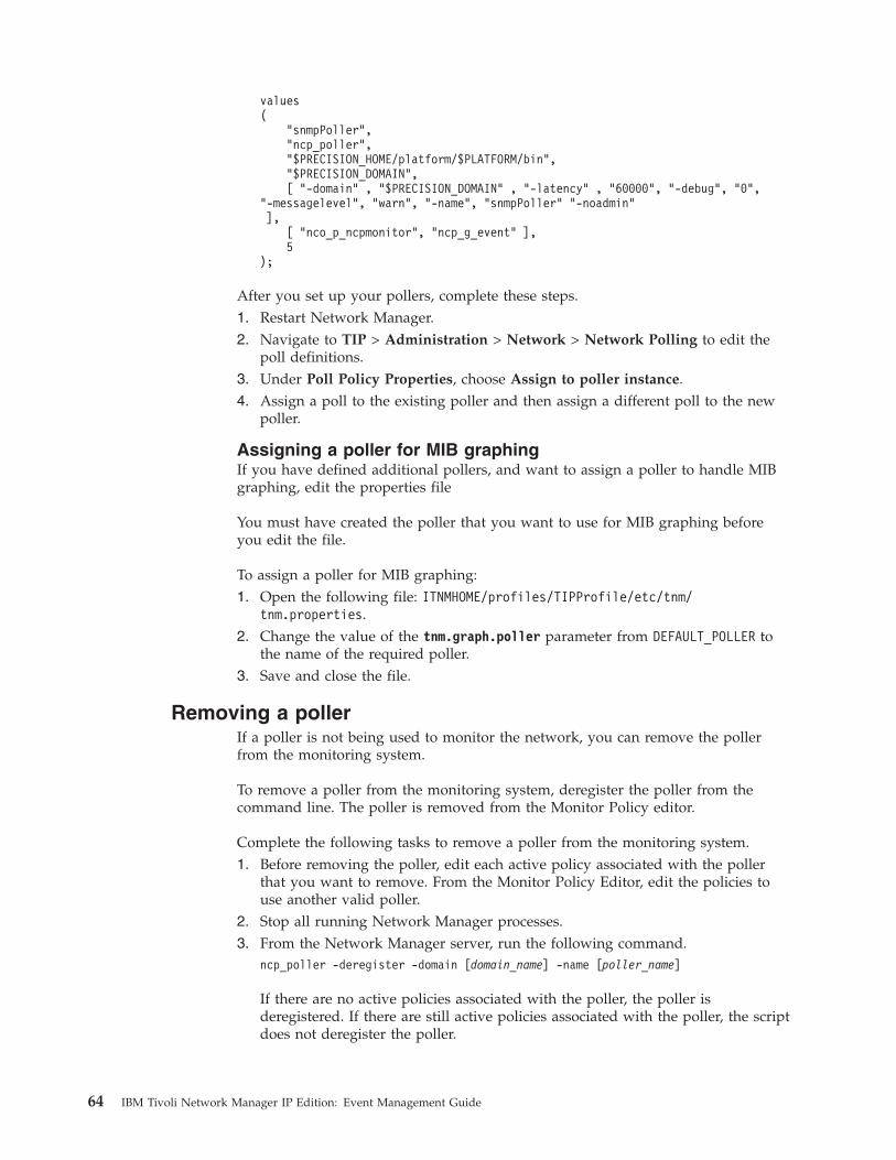
values(
"snmpPoller","ncp_poller","$PRECISION_HOME/platform/$PLATFORM/bin","$PRECISION_DOMAIN",[ "-domain" , "$PRECISION_DOMAIN" , "-latency" , "60000", "-debug", "0",
"-messagelevel", "warn", "-name", "snmpPoller" "-noadmin"],
[ "nco_p_ncpmonitor", "ncp_g_event" ],5
);
After you set up your pollers, complete these steps.1. Restart Network Manager.2. Navigate to TIP > Administration > Network > Network Polling to edit the
poll definitions.3. Under Poll Policy Properties, choose Assign to poller instance.4. Assign a poll to the existing poller and then assign a different poll to the new
poller.
Assigning a poller for MIB graphingIf you have defined additional pollers, and want to assign a poller to handle MIBgraphing, edit the properties file
You must have created the poller that you want to use for MIB graphing beforeyou edit the file.
To assign a poller for MIB graphing:1. Open the following file: ITNMHOME/profiles/TIPProfile/etc/tnm/
tnm.properties.2. Change the value of the tnm.graph.poller parameter from DEFAULT_POLLER to
the name of the required poller.3. Save and close the file.
Removing a pollerIf a poller is not being used to monitor the network, you can remove the pollerfrom the monitoring system.
To remove a poller from the monitoring system, deregister the poller from thecommand line. The poller is removed from the Monitor Policy editor.
Complete the following tasks to remove a poller from the monitoring system.1. Before removing the poller, edit each active policy associated with the poller
that you want to remove. From the Monitor Policy Editor, edit the policies touse another valid poller.
2. Stop all running Network Manager processes.3. From the Network Manager server, run the following command.
ncp_poller -deregister -domain [domain_name] -name [poller_name]
If there are no active policies associated with the poller, the poller isderegistered. If there are still active policies associated with the poller, the scriptdoes not deregister the poller.
64 IBM Tivoli Network Manager IP Edition: Event Management Guide
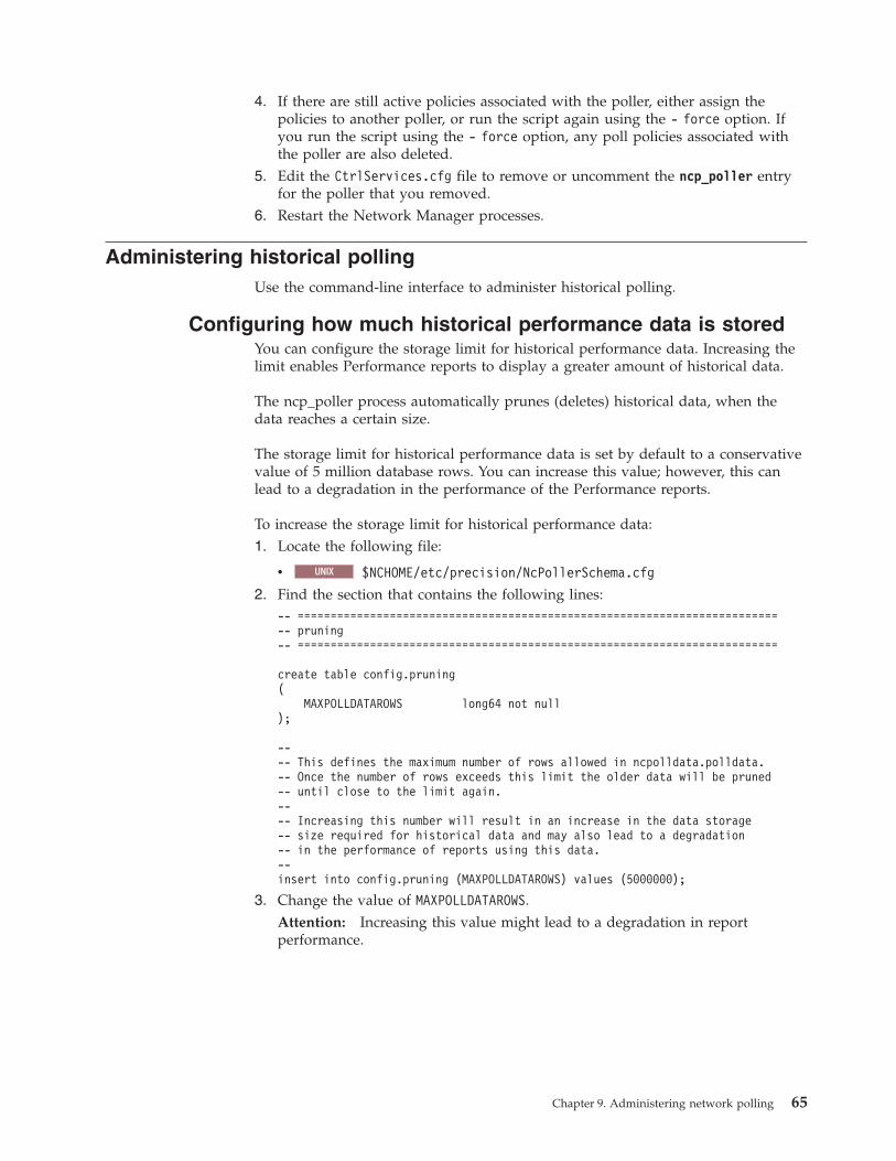
4. If there are still active policies associated with the poller, either assign thepolicies to another poller, or run the script again using the - force option. Ifyou run the script using the - force option, any poll policies associated withthe poller are also deleted.
5. Edit the CtrlServices.cfg file to remove or uncomment the ncp_poller entryfor the poller that you removed.
6. Restart the Network Manager processes.
Administering historical pollingUse the command-line interface to administer historical polling.
Configuring how much historical performance data is storedYou can configure the storage limit for historical performance data. Increasing thelimit enables Performance reports to display a greater amount of historical data.
The ncp_poller process automatically prunes (deletes) historical data, when thedata reaches a certain size.
The storage limit for historical performance data is set by default to a conservativevalue of 5 million database rows. You can increase this value; however, this canlead to a degradation in the performance of the Performance reports.
To increase the storage limit for historical performance data:1. Locate the following file:
v UNIX $NCHOME/etc/precision/NcPollerSchema.cfg
2. Find the section that contains the following lines:-- =========================================================================-- pruning-- =========================================================================
create table config.pruning(
MAXPOLLDATAROWS long64 not null);
---- This defines the maximum number of rows allowed in ncpolldata.polldata.-- Once the number of rows exceeds this limit the older data will be pruned-- until close to the limit again.---- Increasing this number will result in an increase in the data storage-- size required for historical data and may also lead to a degradation-- in the performance of reports using this data.--insert into config.pruning (MAXPOLLDATAROWS) values (5000000);
3. Change the value of MAXPOLLDATAROWS.Attention: Increasing this value might lead to a degradation in reportperformance.
Chapter 9. Administering network polling 65
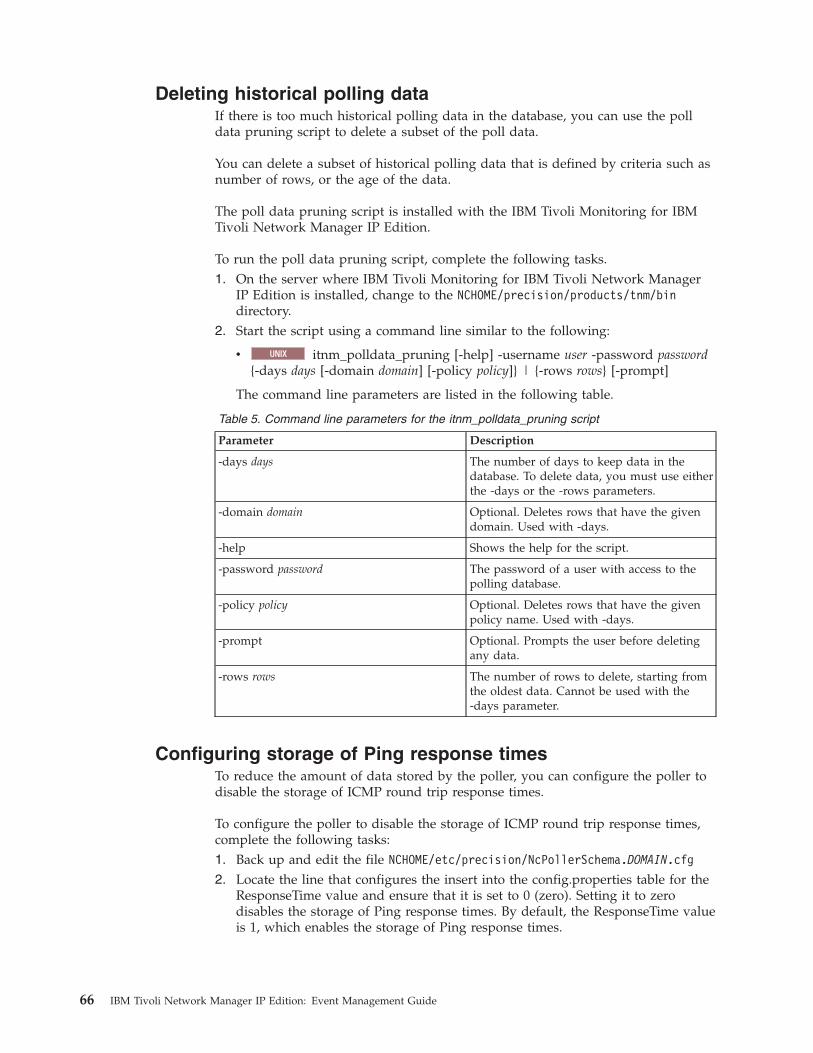
Deleting historical polling dataIf there is too much historical polling data in the database, you can use the polldata pruning script to delete a subset of the poll data.
You can delete a subset of historical polling data that is defined by criteria such asnumber of rows, or the age of the data.
The poll data pruning script is installed with the IBM Tivoli Monitoring for IBMTivoli Network Manager IP Edition.
To run the poll data pruning script, complete the following tasks.1. On the server where IBM Tivoli Monitoring for IBM Tivoli Network Manager
IP Edition is installed, change to the NCHOME/precision/products/tnm/bindirectory.
2. Start the script using a command line similar to the following:
v UNIX itnm_polldata_pruning [-help] -username user -password password{-days days [-domain domain] [-policy policy]} | {-rows rows} [-prompt]
The command line parameters are listed in the following table.
Table 5. Command line parameters for the itnm_polldata_pruning script
Parameter Description
-days days The number of days to keep data in thedatabase. To delete data, you must use eitherthe -days or the -rows parameters.
-domain domain Optional. Deletes rows that have the givendomain. Used with -days.
-help Shows the help for the script.
-password password The password of a user with access to thepolling database.
-policy policy Optional. Deletes rows that have the givenpolicy name. Used with -days.
-prompt Optional. Prompts the user before deletingany data.
-rows rows The number of rows to delete, starting fromthe oldest data. Cannot be used with the-days parameter.
Configuring storage of Ping response timesTo reduce the amount of data stored by the poller, you can configure the poller todisable the storage of ICMP round trip response times.
To configure the poller to disable the storage of ICMP round trip response times,complete the following tasks:1. Back up and edit the file NCHOME/etc/precision/NcPollerSchema.DOMAIN.cfg
2. Locate the line that configures the insert into the config.properties table for theResponseTime value and ensure that it is set to 0 (zero). Setting it to zerodisables the storage of Ping response times. By default, the ResponseTime valueis 1, which enables the storage of Ping response times.
66 IBM Tivoli Network Manager IP Edition: Event Management Guide
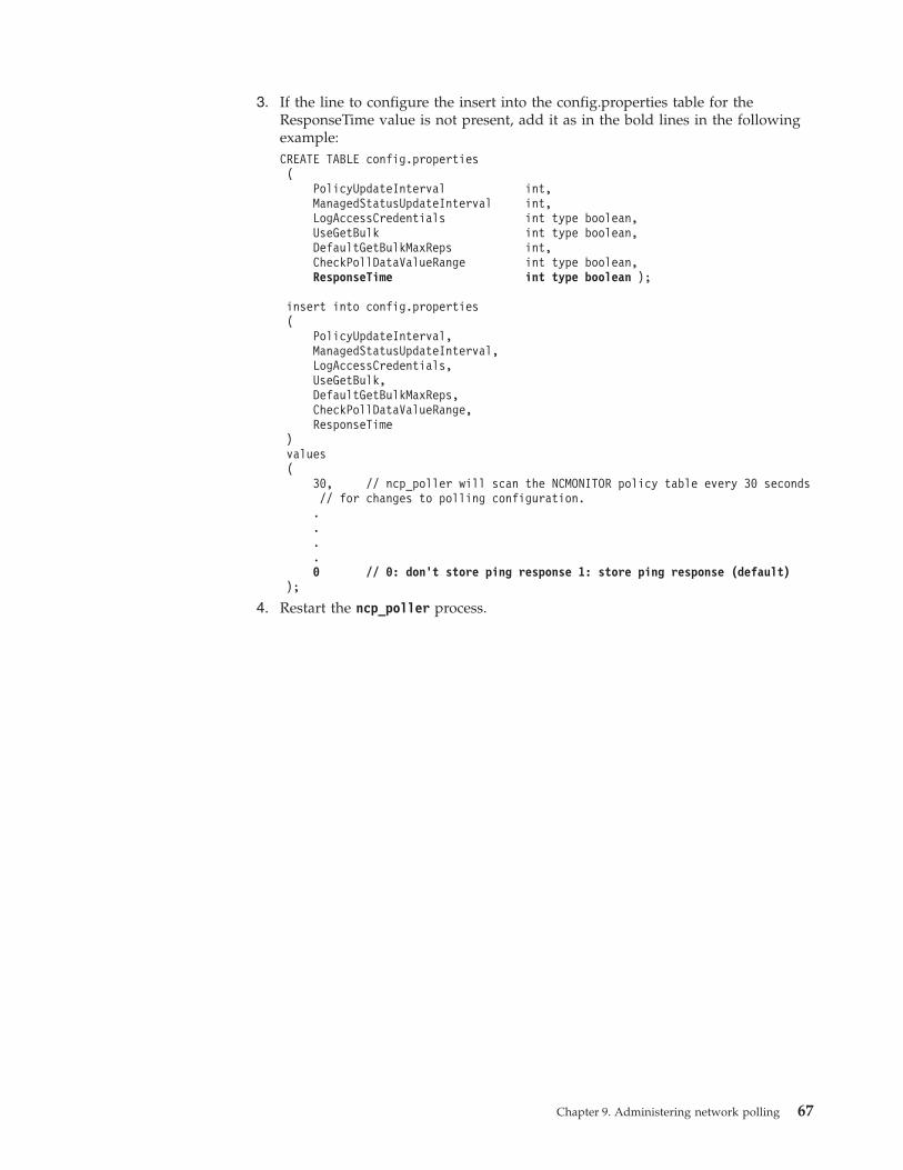
3. If the line to configure the insert into the config.properties table for theResponseTime value is not present, add it as in the bold lines in the followingexample:CREATE TABLE config.properties(
PolicyUpdateInterval int,ManagedStatusUpdateInterval int,LogAccessCredentials int type boolean,UseGetBulk int type boolean,DefaultGetBulkMaxReps int,CheckPollDataValueRange int type boolean,ResponseTime int type boolean );
insert into config.properties(
PolicyUpdateInterval,ManagedStatusUpdateInterval,LogAccessCredentials,UseGetBulk,DefaultGetBulkMaxReps,CheckPollDataValueRange,ResponseTime
)values(
30, // ncp_poller will scan the NCMONITOR policy table every 30 seconds// for changes to polling configuration.....0 // 0: don’t store ping response 1: store ping response (default)
);
4. Restart the ncp_poller process.
Chapter 9. Administering network polling 67

68 IBM Tivoli Network Manager IP Edition: Event Management Guide
Chapter 10. Troubleshooting ping polling of the network
Use this information to help you ensure that the important IP addresses in yournetwork are being ping polled as expected by Network Manager and, if not, toprovide information to resolve the problem.
By default, the tables and views defined in the $NCHOME/precision/scripts/SQL/createPollLogTables.sql file are added to the NCMONITOR schema as part of theNetwork Manager installation. These tables and views store the results of thediagnostic operations performed in this procedure.
Note: This mechanism is for ping polling policies only, not for SNMP pollingpolicies.
This procedure includes a step for taking a snapshot of the current ping pollingstatus within a specified network domainAfter starting the Network Managerpolling process, you must allow at least two polling intervals before taking the firstsnapshot. A restart of the system is not necessary.
Given a set of IP addresses, the scripts described in this task provide insight intowhether the poller is pinging those IP addresses, and if not, provide an indicationof what the problem is. There are a number of reasons why IP addresses might notbe being polled including the following:v The device specified in the poll policy was not discovered.v The device or interface is not included in any of the ping policy scopes.v The device or interface has been marked as unmanaged from one of the
topology visualization GUIs.v The interface was marked as unmanaged at discovery time or determined to be
unroutable.
For more information on the scripts described in this task, see the IBM TivoliNetwork Manager IP Edition Administration Guide.
Note: These scripts are a verification and diagnostic tool only and have no effecton the actual polling of the devices; polling of devices is governed solely by thepoll policies set up using the Network Polling GUI.1. Add the list of IP addresses whose polling you want to monitor using the
ncp_upload_expected_ips.pl script. Issue the following command:$NCHOME/precision/bin/ncp_perl $NCHOME/precision/scripts/perl/scripts/ncp_upload_expected_ips.pl -domain DOMAIN_NAME -file FILENAME -passwordPASSWORD Where:v DOMAIN_NAME is the name of domain that contains the IP addresses. The
list of IP addresses will only be compared with IP addresses in this domain.v FILENAME is a plain text file of IP addresses, separated by whitespace (for
example, one IP address per line). This only accepts IPv4 addresses. The fileis expected to contain just IP addresses in standard dot notation.
v PASSWORD is the database password used to access the NCIM andNCMONITOR schemas.
© Copyright IBM Corp. 2006, 2013 69

Note: Only repeat this operation if there are changes to the list of IP addresseswhose polling you want to monitor. Otherwise, this is a one-time operationonly per domain.
2. Periodically, or when required for troubleshooting purposes, take a snapshot ofthe current ping polling status within the domain specified in the previousstep. Issue the following command:$NCHOME/precision/bin/ncp_perl$NCHOME/precision/scripts/perl/scripts/ncp_ping_poller_snapshot.pl-domain DOMAIN_NAME -password PASSWORD Where:v DOMAIN_NAME is the name of domain within which to take a snapshot of
the current ping polling status.v PASSWORD is the database password used to access the NCIM and
NCMONITOR schemas.
The results of the operation are stored in the pollLog database table within theNCMONITOR schema.
3. Report on the entities that are not being polled.Run the report of the status ofentities polled or not polled by the Network Manager polling process. Issue thefollowing command: $NCHOME/precision/bin/ncp_perl $NCHOME/precision/scripts/perl/scripts/ ncp_polling_exceptions.pl -domain DOMAIN_NAME [-notpolled ] [-format LIST | REPORT ] Where:v DOMAIN_NAME is the name of domain within which to report on current ping
polling status.v -notpolled: this optional parameter outputs a list of IP addresses that are not
polled as compared with the list of expected IP addresses. This output is inLIST format only.
v -format LIST | REPORT: this optional parameter specifies whether the outputshould be in report or list format.
This command outputs two lists: a list of IP addresses that you want to polland a list of IP addresses that are not being polled. You can see at a glance ifany of the IP addresses that you want to poll are not being polled.
Related reference:“Ping polling status tables” on page 202The NCMONITOR ping polling status tables enable diagnostic operations to beperformed on network ping polling.
70 IBM Tivoli Network Manager IP Edition: Event Management Guide
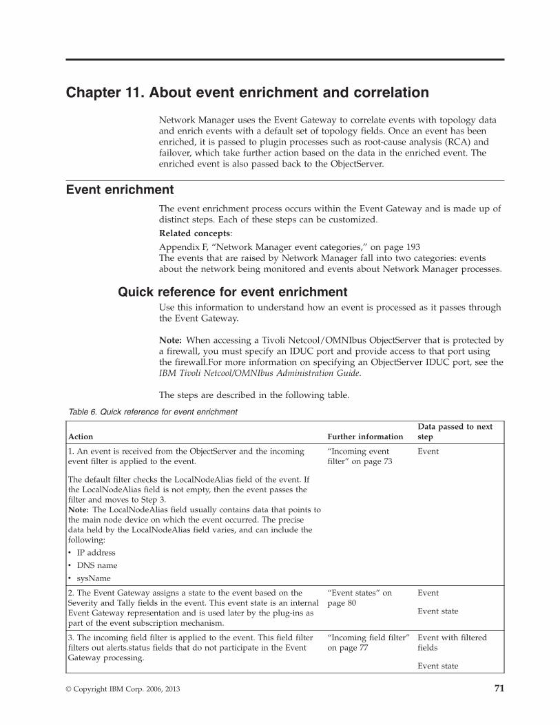
Chapter 11. About event enrichment and correlation
Network Manager uses the Event Gateway to correlate events with topology dataand enrich events with a default set of topology fields. Once an event has beenenriched, it is passed to plugin processes such as root-cause analysis (RCA) andfailover, which take further action based on the data in the enriched event. Theenriched event is also passed back to the ObjectServer.
Event enrichmentThe event enrichment process occurs within the Event Gateway and is made up ofdistinct steps. Each of these steps can be customized.Related concepts:Appendix F, “Network Manager event categories,” on page 193The events that are raised by Network Manager fall into two categories: eventsabout the network being monitored and events about Network Manager processes.
Quick reference for event enrichmentUse this information to understand how an event is processed as it passes throughthe Event Gateway.
Note: When accessing a Tivoli Netcool/OMNIbus ObjectServer that is protected bya firewall, you must specify an IDUC port and provide access to that port usingthe firewall.For more information on specifying an ObjectServer IDUC port, see theIBM Tivoli Netcool/OMNIbus Administration Guide.
The steps are described in the following table.
Table 6. Quick reference for event enrichment
Action Further informationData passed to nextstep
1. An event is received from the ObjectServer and the incomingevent filter is applied to the event.
The default filter checks the LocalNodeAlias field of the event. Ifthe LocalNodeAlias field is not empty, then the event passes thefilter and moves to Step 3.Note: The LocalNodeAlias field usually contains data that points tothe main node device on which the event occurred. The precisedata held by the LocalNodeAlias field varies, and can include thefollowing:
v IP address
v DNS name
v sysName
“Incoming eventfilter” on page 73
Event
2. The Event Gateway assigns a state to the event based on theSeverity and Tally fields in the event. This event state is an internalEvent Gateway representation and is used later by the plug-ins aspart of the event subscription mechanism.
“Event states” onpage 80
Event
Event state
3. The incoming field filter is applied to the event. This field filterfilters out alerts.status fields that do not participate in the EventGateway processing.
“Incoming field filter”on page 77
Event with filteredfields
Event state
© Copyright IBM Corp. 2006, 2013 71
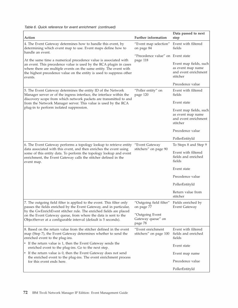
Table 6. Quick reference for event enrichment (continued)
Action Further informationData passed to nextstep
4. The Event Gateway determines how to handle this event, bydetermining which event map to use. Event maps define how tohandle an event.
At the same time a numerical precedence value is associated withan event. This precedence value is used by the RCA plugin in caseswhere there are multiple events on the same entity. The event withthe highest precedence value on the entity is used to suppress otherevents.
“Event map selection”on page 84
“Precedence value” onpage 118
Event with filteredfields
Event state
Event map fields, suchas event map nameand event enrichmentstitcher
Precedence value
5. The Event Gateway determines the entity ID of the NetworkManager server or of the ingress interface, the interface within thediscovery scope from which network packets are transmitted to andfrom the Network Manager server. This value is used by the RCAplug-in to perform isolated suppression.
“Poller entity” onpage 120
Event with filteredfields
Event state
Event map fields, suchas event map nameand event enrichmentstitcher
Precedence value
PollerEntityId
6. The Event Gateway performs a topology lookup to retrieve entitydata associated with this event, and then enriches the event usingsome of this entity data. To perform the topology lookup and eventenrichment, the Event Gateway calls the stitcher defined in theevent map.
“Event Gatewaystitchers” on page 90
To Steps 8 and Step 9
Event with filteredfields and enrichedfields
Event state
Precedence value
PollerEntityId
Return value fromstitcher
7. The outgoing field filter is applied to the event. This filter onlypasses the fields enriched by the Event Gateway, and in particular,by the GwEnrichEvent stitcher rule. The enriched fields are placedon the Event Gateway queue, from where the data is sent to theObjectServer at a configurable interval (default is 5 seconds).
“Outgoing field filter”on page 77
“Outgoing EventGateway queue” onpage 78
Fields enriched byEvent Gateway
8. Based on the return value from the stitcher defined in the eventmap (Step 7), the Event Gateway determines whether to send theenriched event to the plug-ins.
v If the return value is 1, then the Event Gateway sends theenriched event to the plug-ins. Go to the next step.
v If the return value is 0, then the Event Gateway does not sendthe enriched event to the plug-ins. The event enrichment processfor this event ends here.
“Event enrichmentstitchers” on page 100
Event with filteredfields and enrichedfields
Event state
Event map name
Precedence value
PollerEntityId
72 IBM Tivoli Network Manager IP Edition: Event Management Guide
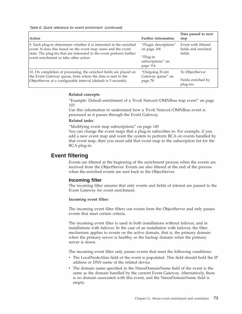
Table 6. Quick reference for event enrichment (continued)
Action Further informationData passed to nextstep
9. Each plug-in determines whether it is interested in the enrichedevent. It does this based on the event map name and the eventstate. The plug-ins that are interested in the event perform furtherevent enrichment or take other action.
“Plugin descriptions”on page 106
“Plug-insubscriptions” onpage 114
Event with filteredfields and enrichedfields
10. On completion of processing, the enriched fields are placed onthe Event Gateway queue, from where the data is sent to theObjectServer at a configurable interval (default is 5 seconds).
“Outgoing EventGateway queue” onpage 78
To ObjectServer
Fields enriched byplug-ins
Related concepts:“Example: Default enrichment of a Tivoli Netcool/OMNIbus trap event” on page103Use this information to understand how a Tivoli Netcool/OMNIbus event isprocessed as it passes through the Event Gateway.Related tasks:“Modifying event map subscriptions” on page 149You can change the event maps that a plug-in subscribes to. For example, if youadd a new event map and want the system to perform RCA on events handled bythat event map, then you must add that event map to the subscription list for theRCA plug-in.
Event filteringEvents are filtered at the beginning of the enrichment process when the events arereceived from the ObjectServer. Events are also filtered at the end of the processwhen the enriched events are sent back to the ObjectServer.
Incoming filterThe incoming filter ensures that only events and fields of interest are passed to theEvent Gateway for event enrichment.
Incoming event filter:
The incoming event filter filters out events from the ObjectServer and only passesevents that meet certain criteria.
The incoming event filter is used in both installations without failover, and ininstallations with failover. In the case of an installation with failover, the filtermechanism applies to events on the active domain, that is, the primary domainwhen the primary server is healthy, or the backup domain when the primaryserver is down.
The incoming event filter only passes events that meet the following conditions:v The LocalNodeAlias field of the event is populated. This field should hold the IP
address or DNS name of the related device.v The domain name specified in the NmosDomainName field of the event is the
same as the domain handled by the current Event Gateway. Alternatively, thereis no domain associated with this event, and the NmosDomainName field isempty.
Chapter 11. About event enrichment and correlation 73

The incoming event filter can handle events in both single domain andmultidomain systems.
Single domain and multidomain handling
In a single domain system, there is only one Event Gateway process. All eventsthat have a domain set in the NmosDomainName field have the same domainassignment as this Event Gateway.
In a multiple domain system, there are multiple Event Gateway processes, one foreach domain. Each Event Gateway process receives events from the ObjectServerand filters the events so that it only receives events for its own domain. TheObjectServer performs deduplication and matching of problem and resolutionevents based on the following alerts.status fields: AlertKey, Identifier, and Domain.The inclusion of the Domain field ensures that all deduplication and matching ofproblem and resolution events is domain specific.
Events with no domain
Events that come from sources outside of Network Manager, for example, TivoliNetcool/OMNIbus syslog or trap probes, do not have a domain setting the firsttime that they pass through an Event Gateway. In a single domain system eventswith no domain setting pass the incoming event filter and the Event Gatewaydetermines the domain associated with the event as part of the topology lookupperformed during event enrichment.
In a multidomain system, the first Event Gateway that encounters the event withno domain passes it through the incoming event filter and proceeds to process it.However, if the topology lookup fails to find an entity for the event, then the eventwill be rejected by the Event Gateway without any event enrichment. The event isthen picked up by a different Event Gateway, which also attempts to match theevent to a device in its domain. This process continues until the event eventually isprocessed by an Event Gateway that is able to match an entity to the event.Related reference:“config.nco2ncp table” on page 223The config.nco2ncp table is used to filter events being passed from TivoliNetcool/OMNIbus to Network Manager.
Incoming event filter: default configuration:
This example shows how the incoming event filter is configured in theEventGatewaySchema.cfg configuration file. This standard insert for the incomingevent filter handles both single-domain and multi-domain systems.
The incoming event filter is configured in the EventGatewaySchema.cfgconfiguration file. This file is located at: $NCHOME/etc/precision/EventGatewaySchema.cfg.
The following table describes the relevant lines from this insert.
Table 7. Lines of code relevant to the incoming event filter
Line numbers Description
1 Configure the incoming filter by making an insert into the config.nco2ncptable.
3 Specify an insert into the EventFilter field of the config.nco2ncp table.
74 IBM Tivoli Network Manager IP Edition: Event Management Guide
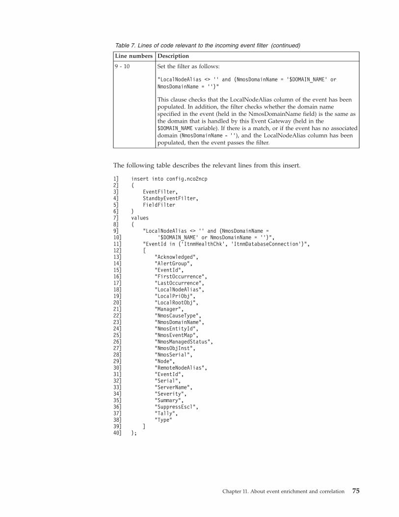
Table 7. Lines of code relevant to the incoming event filter (continued)
Line numbers Description
9 - 10 Set the filter as follows:
"LocalNodeAlias <> ’’ and (NmosDomainName = ’$DOMAIN_NAME’ orNmosDomainName = ’’)"
This clause checks that the LocalNodeAlias column of the event has beenpopulated. In addition, the filter checks whether the domain namespecified in the event (held in the NmosDomainName field) is the same asthe domain that is handled by this Event Gateway (held in the$DOMAIN_NAME variable). If there is a match, or if the event has no associateddomain (NmosDomainName - ’’), and the LocalNodeAlias column has beenpopulated, then the event passes the filter.
The following table describes the relevant lines from this insert.
1]2]3]4]5]6]7]8]9]10]11]12]13]14]15]16]17]18]19]20]21]22]23]24]25]26]27]28]29]30]31]32]33]34]35]36]37]38]39]40]
insert into config.nco2ncp(
EventFilter,StandbyEventFilter,FieldFilter
)values(
"LocalNodeAlias <> ’’ and (NmosDomainName =’$DOMAIN_NAME’ or NmosDomainName = ’’)",
"EventId in (’ItnmHealthChk’, ’ItnmDatabaseConnection’)",[
"Acknowledged","AlertGroup","EventId","FirstOccurrence","LastOccurrence","LocalNodeAlias","LocalPriObj","LocalRootObj","Manager","NmosCauseType","NmosDomainName","NmosEntityId","NmosEventMap","NmosManagedStatus","NmosObjInst","NmosSerial","Node","RemoteNodeAlias","EventId","Serial","ServerName","Severity","Summary","SuppressEscl","Tally","Type"
]);
Chapter 11. About event enrichment and correlation 75
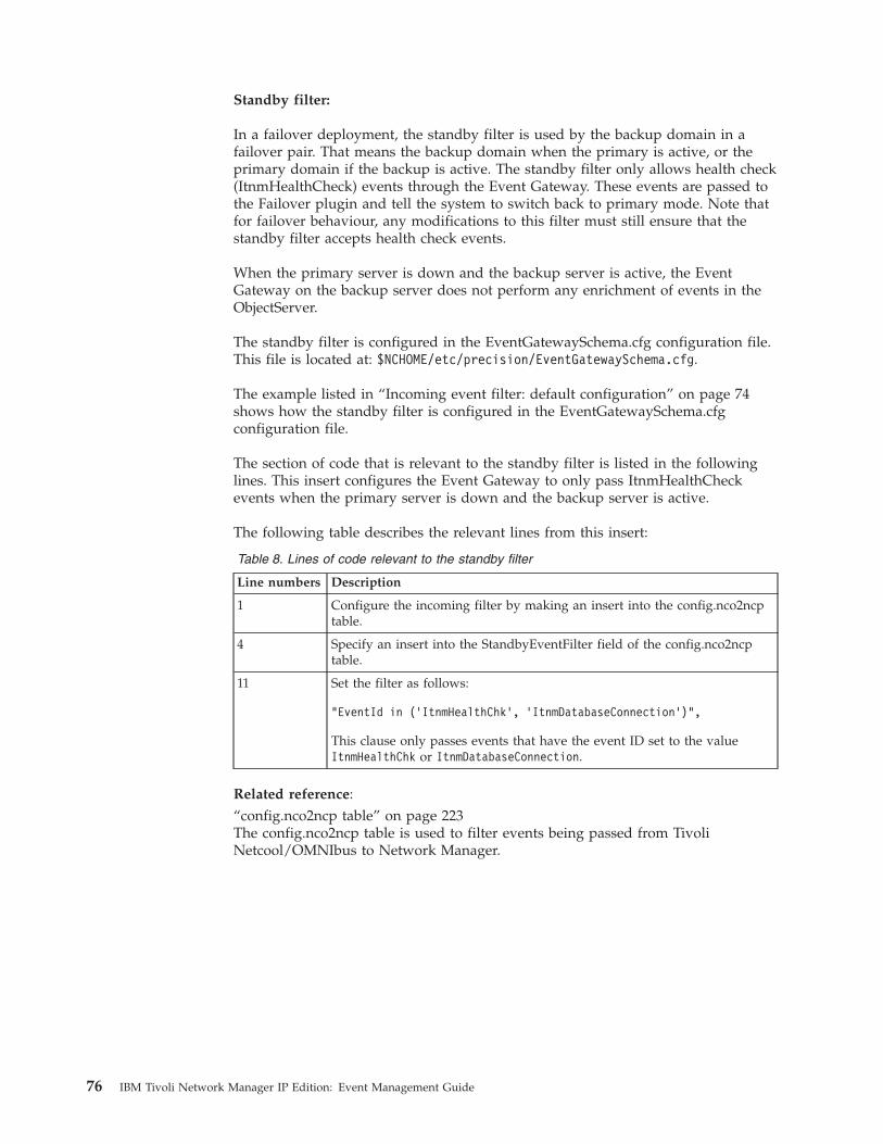
Standby filter:
In a failover deployment, the standby filter is used by the backup domain in afailover pair. That means the backup domain when the primary is active, or theprimary domain if the backup is active. The standby filter only allows health check(ItnmHealthCheck) events through the Event Gateway. These events are passed tothe Failover plugin and tell the system to switch back to primary mode. Note thatfor failover behaviour, any modifications to this filter must still ensure that thestandby filter accepts health check events.
When the primary server is down and the backup server is active, the EventGateway on the backup server does not perform any enrichment of events in theObjectServer.
The standby filter is configured in the EventGatewaySchema.cfg configuration file.This file is located at: $NCHOME/etc/precision/EventGatewaySchema.cfg.
The example listed in “Incoming event filter: default configuration” on page 74shows how the standby filter is configured in the EventGatewaySchema.cfgconfiguration file.
The section of code that is relevant to the standby filter is listed in the followinglines. This insert configures the Event Gateway to only pass ItnmHealthCheckevents when the primary server is down and the backup server is active.
The following table describes the relevant lines from this insert:
Table 8. Lines of code relevant to the standby filter
Line numbers Description
1 Configure the incoming filter by making an insert into the config.nco2ncptable.
4 Specify an insert into the StandbyEventFilter field of the config.nco2ncptable.
11 Set the filter as follows:
"EventId in (’ItnmHealthChk’, ’ItnmDatabaseConnection’)",
This clause only passes events that have the event ID set to the valueItnmHealthChk or ItnmDatabaseConnection.
Related reference:“config.nco2ncp table” on page 223The config.nco2ncp table is used to filter events being passed from TivoliNetcool/OMNIbus to Network Manager.
76 IBM Tivoli Network Manager IP Edition: Event Management Guide
Incoming field filter:
For each event that passes the incoming event filter, the field filter specifies asubset of alerts.status fields that are passed through to the event enrichmentprocess. If the field filter is empty then all alerts.status fields are are passedthrough to the event enrichment process. The purpose of this filter is to limit thefields passed through to the minimum required set in order to lighten theprocessing load.
The incoming event filter is configured in the EventGatewaySchema.cfgconfiguration file. This file is located at: $NCHOME/etc/precision/EventGatewaySchema.cfg.
The example listed in “Incoming event filter: default configuration” on page 74shows how the incoming field filter is configured in the EventGatewaySchema.cfgconfiguration file.
The section of code that is relevant to the incoming field filter is listed in thefollowing lines from the example. For each event that the ObjectServer passes tothe Event Gateway, the incoming field filter specifies a subset of alerts.status fieldsthat are passed through to the event enrichment process.
The following table describes the relevant lines from this example:
Table 9. Lines of code relevant to the incoming field filter
Line numbers Description
1 Configure the incoming filter by making an insert into the config.ncp2ncotable.
5 Specify an insert into the FieldFilter field of the config.ncp2nco table.
11-38 Only pass the alerts.status fields specified in lines 13 to 38.Note: If you configure extra event enrichment, you might need to addfields to this list.
Outgoing field filterThe outgoing field filter defines the set of ObjectServer fields that may be updatedby the Event Gateway.
Event enrichment is performed by the GwEnrichEvent() stitcher rule. Of the fieldsenriched with that rule, only those listed in this filter are transmitted to the ObjectServer. Some event enrichment is intended purely to provide data for use by EventGateway plug-ins. The enriched fields intended only for use by plug-ins do notneed to be specified in the outgoing field filter. The outgoing field filter works onany data passed to the GwEnrichEvent() rule
Note: If you customize event enrichment to add extra enriched fields to the event,then you must update the outgoing field filter to include these extra enrichedfields. For example, if you want enrich events so that any alert on a Cisco routersalerts is increased to critical severity (severity 5) then you must add Severity to thelist of fields in the outgoing field filter.
The outgoing field filter is configured in the EventGatewaySchema.cfgconfiguration file. This file is located at: $NCHOME/etc/precision/EventGatewaySchema.cfg.
Chapter 11. About event enrichment and correlation 77
The following example shows how the outgoing field filter is configured in theEventGatewaySchema.cfg configuration file.
The section of code that is relevant to the outgoing field filter is listed in thefollowing lines from the example. Each time the Event Gateway passes enrichedfields back to the ObjectServer, only the fields listed in this filter are transmitted.Any other fields are ignored.
The following table describes the relevant lines from this example:
Table 10. Lines of code relevant to the incoming event filter
Line numbers Description
1 Configure the outgoing field filter by making an insert into theconfig.ncp2nco table.
3 Specify an insert into the FieldFilter field of the config.ncp2nco table.
5-14 Only pass the fields specified in lines 5 to 14 back to the ObjectServer.Note: If you configure extra event enrichment, you must add fields to thislist.
1]2]3]4]5]6]7]8]9]10]11]12]13]14]15]
insert into config.ncp2nco(
FieldFilter)values(
["NmosCauseType","NmosDomainName","NmosEntityId","NmosManagedStatus","NmosObjInst","NmosSerial"
]);
Related tasks:“Example: Enriching an event with main node device location” on page 140You can configure event enrichment so that the location of the main node deviceassociated with an event is added to a field in the event.“Example: Enriching an event with interface name” on page 141You can configure event enrichment so that for all interface events, the name of theinterface on which the event occurred is added to a field in the event.
Outgoing Event Gateway queue:
The outgoing Event Gateway queue receives enriched events from the EventGateway stitchers (main event enrichment) and from the plug-ins. In order tominimize the number of updates and hence minimize the load on the ObjectServer,updates to the Object Server are placed in a queue, aggregated, and sent to theObjectServer at a specified interval. The default is 5 seconds.
The outgoing Event Gateway queue receives enriched events from both the EventGateway stitchers (main event enrichment) and from the plug-ins, as shown in thefollowing diagram.
78 IBM Tivoli Network Manager IP Edition: Event Management Guide
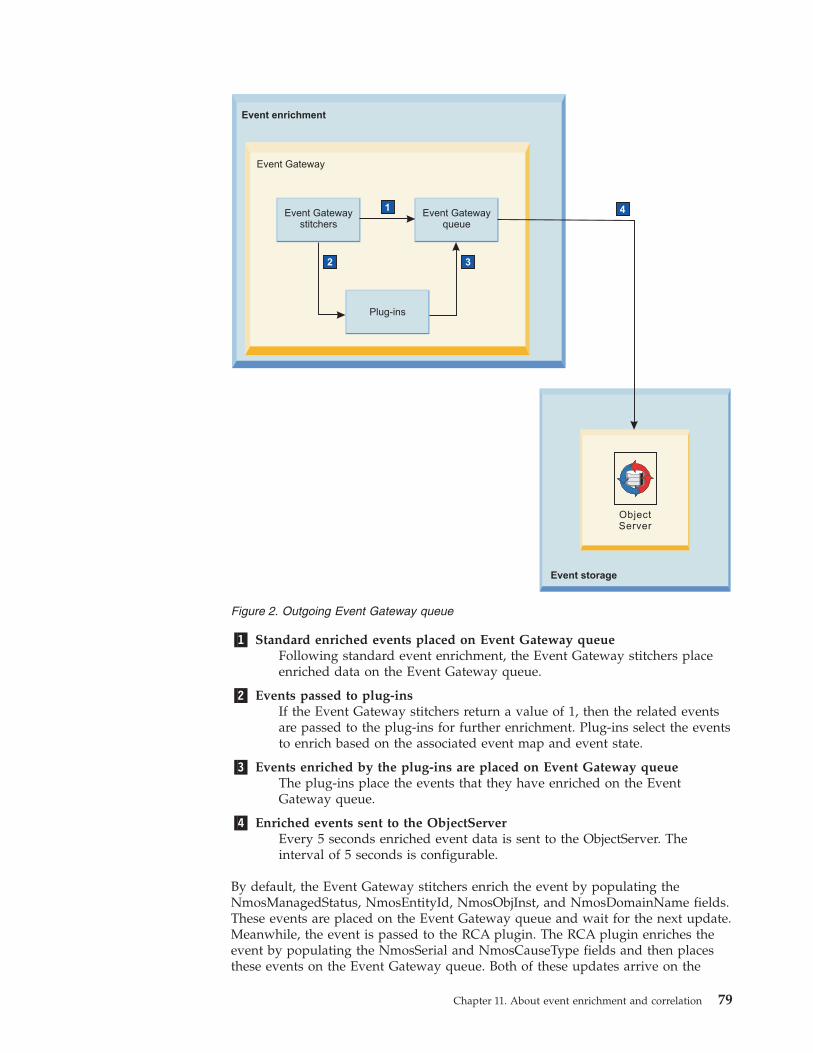
�1� Standard enriched events placed on Event Gateway queueFollowing standard event enrichment, the Event Gateway stitchers placeenriched data on the Event Gateway queue.
�2� Events passed to plug-insIf the Event Gateway stitchers return a value of 1, then the related eventsare passed to the plug-ins for further enrichment. Plug-ins select the eventsto enrich based on the associated event map and event state.
�3� Events enriched by the plug-ins are placed on Event Gateway queueThe plug-ins place the events that they have enriched on the EventGateway queue.
�4� Enriched events sent to the ObjectServerEvery 5 seconds enriched event data is sent to the ObjectServer. Theinterval of 5 seconds is configurable.
By default, the Event Gateway stitchers enrich the event by populating theNmosManagedStatus, NmosEntityId, NmosObjInst, and NmosDomainName fields.These events are placed on the Event Gateway queue and wait for the next update.Meanwhile, the event is passed to the RCA plugin. The RCA plugin enriches theevent by populating the NmosSerial and NmosCauseType fields and then placesthese events on the Event Gateway queue. Both of these updates arrive on the
Event Gateway
1
2
Event Gatewaystitchers
Event Gatewayqueue
Plug-ins
ObjectServer
Event enrichment
Event storage
3
4
Figure 2. Outgoing Event Gateway queue
Chapter 11. About event enrichment and correlation 79
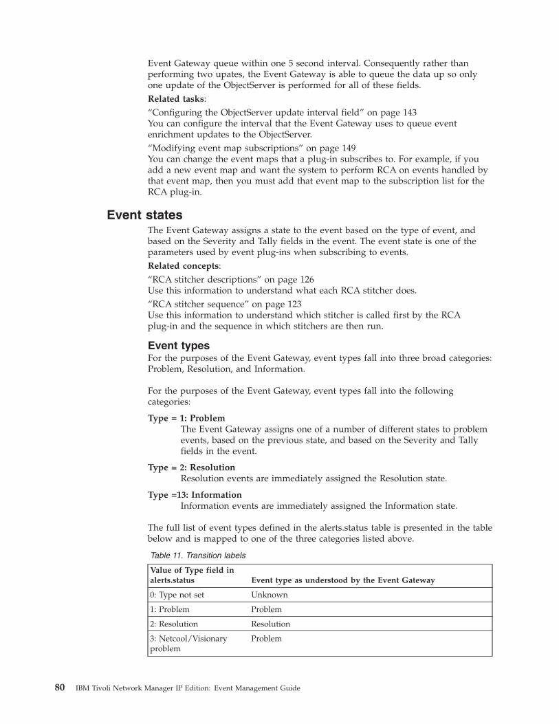
Event Gateway queue within one 5 second interval. Consequently rather thanperforming two upates, the Event Gateway is able to queue the data up so onlyone update of the ObjectServer is performed for all of these fields.Related tasks:“Configuring the ObjectServer update interval field” on page 143You can configure the interval that the Event Gateway uses to queue eventenrichment updates to the ObjectServer.“Modifying event map subscriptions” on page 149You can change the event maps that a plug-in subscribes to. For example, if youadd a new event map and want the system to perform RCA on events handled bythat event map, then you must add that event map to the subscription list for theRCA plug-in.
Event statesThe Event Gateway assigns a state to the event based on the type of event, andbased on the Severity and Tally fields in the event. The event state is one of theparameters used by event plug-ins when subscribing to events.Related concepts:“RCA stitcher descriptions” on page 126Use this information to understand what each RCA stitcher does.“RCA stitcher sequence” on page 123Use this information to understand which stitcher is called first by the RCAplug-in and the sequence in which stitchers are then run.
Event typesFor the purposes of the Event Gateway, event types fall into three broad categories:Problem, Resolution, and Information.
For the purposes of the Event Gateway, event types fall into the followingcategories:
Type = 1: ProblemThe Event Gateway assigns one of a number of different states to problemevents, based on the previous state, and based on the Severity and Tallyfields in the event.
Type = 2: ResolutionResolution events are immediately assigned the Resolution state.
Type =13: InformationInformation events are immediately assigned the Information state.
The full list of event types defined in the alerts.status table is presented in the tablebelow and is mapped to one of the three categories listed above.
Table 11. Transition labels
Value of Type field inalerts.status Event type as understood by the Event Gateway
0: Type not set Unknown
1: Problem Problem
2: Resolution Resolution
3: Netcool/Visionaryproblem
Problem
80 IBM Tivoli Network Manager IP Edition: Event Management Guide
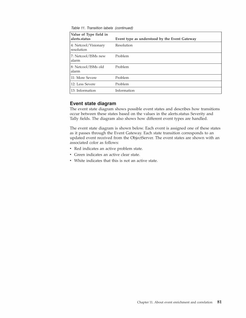
Table 11. Transition labels (continued)
Value of Type field inalerts.status Event type as understood by the Event Gateway
4: Netcool/Visionaryresolution
Resolution
7: Netcool/ISMs newalarm
Problem
8: Netcool/ISMs oldalarm
Problem
11: More Severe Problem
12: Less Severe Problem
13: Information Information
Event state diagramThe event state diagram shows possible event states and describes how transitionsoccur between these states based on the values in the alerts.status Severity andTally fields. The diagram also shows how different event types are handled.
The event state diagram is shown below. Each event is assigned one of these statesas it passes through the Event Gateway. Each state transition corresponds to anupdated event received from the ObjectServer. The event states are shown with anassociated color as follows:v Red indicates an active problem state.v Green indicates an active clear state.v White indicates that this is not an active state.
Chapter 11. About event enrichment and correlation 81
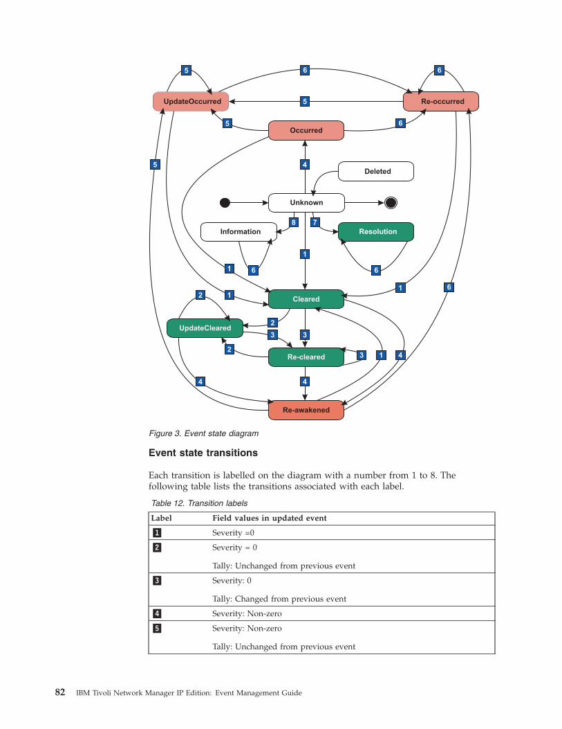
Event state transitions
Each transition is labelled on the diagram with a number from 1 to 8. Thefollowing table lists the transitions associated with each label.
Table 12. Transition labels
Label Field values in updated event
�1� Severity =0
�2� Severity = 0
Tally: Unchanged from previous event
�3� Severity: 0
Tally: Changed from previous event
�4� Severity: Non-zero
�5� Severity: Non-zero
Tally: Unchanged from previous event
1
78
1
1
4
2
2
44
41
6
1
5 6
5
6 65
5
2
3 3
3
66
UpdateOccurred Re-occurred
Occurred
Deleted
Cleared
Re-cleared
UpdateCleared
Re-awakened
ResolutionInformation
Unknown
Figure 3. Event state diagram
82 IBM Tivoli Network Manager IP Edition: Event Management Guide
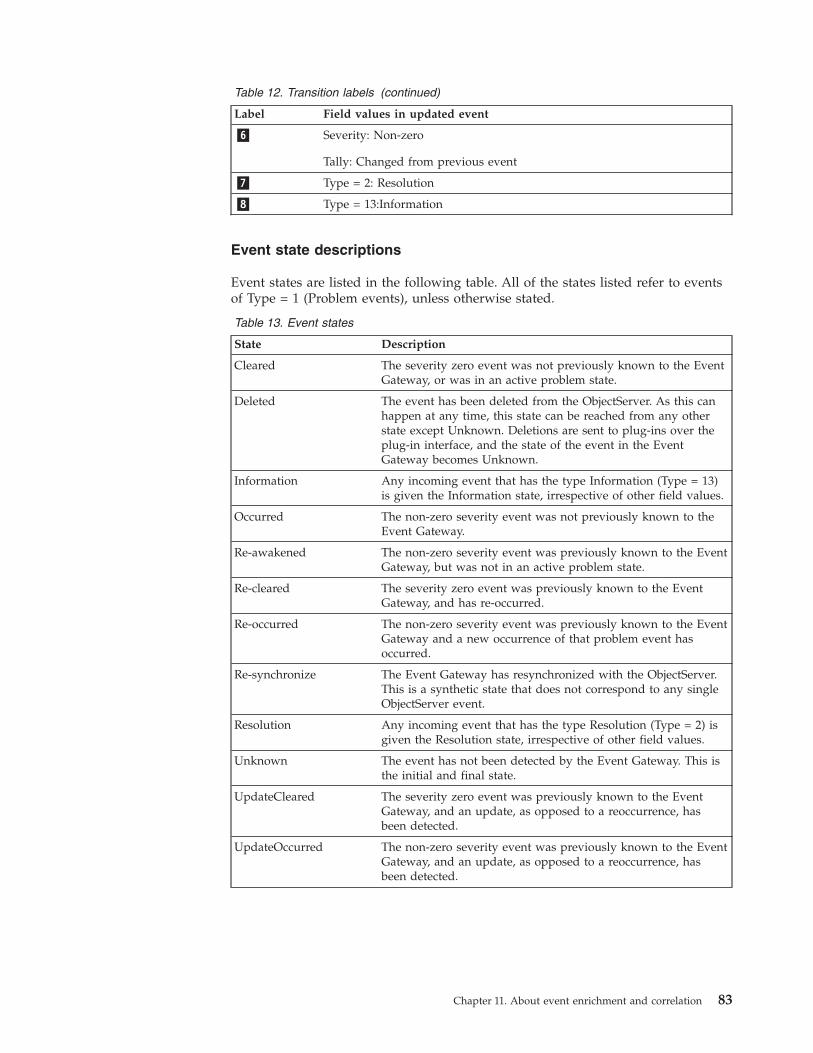
Table 12. Transition labels (continued)
Label Field values in updated event
�6� Severity: Non-zero
Tally: Changed from previous event
�7� Type = 2: Resolution
�8� Type = 13:Information
Event state descriptions
Event states are listed in the following table. All of the states listed refer to eventsof Type = 1 (Problem events), unless otherwise stated.
Table 13. Event states
State Description
Cleared The severity zero event was not previously known to the EventGateway, or was in an active problem state.
Deleted The event has been deleted from the ObjectServer. As this canhappen at any time, this state can be reached from any otherstate except Unknown. Deletions are sent to plug-ins over theplug-in interface, and the state of the event in the EventGateway becomes Unknown.
Information Any incoming event that has the type Information (Type = 13)is given the Information state, irrespective of other field values.
Occurred The non-zero severity event was not previously known to theEvent Gateway.
Re-awakened The non-zero severity event was previously known to the EventGateway, but was not in an active problem state.
Re-cleared The severity zero event was previously known to the EventGateway, and has re-occurred.
Re-occurred The non-zero severity event was previously known to the EventGateway and a new occurrence of that problem event hasoccurred.
Re-synchronize The Event Gateway has resynchronized with the ObjectServer.This is a synthetic state that does not correspond to any singleObjectServer event.
Resolution Any incoming event that has the type Resolution (Type = 2) isgiven the Resolution state, irrespective of other field values.
Unknown The event has not been detected by the Event Gateway. This isthe initial and final state.
UpdateCleared The severity zero event was previously known to the EventGateway, and an update, as opposed to a reoccurrence, hasbeen detected.
UpdateOccurred The non-zero severity event was previously known to the EventGateway, and an update, as opposed to a reoccurrence, hasbeen detected.
Chapter 11. About event enrichment and correlation 83
Event handlingEvent handling involves determining how to map each type of event from theObjectServer to an entity in the topology data.
Event mapsEvent handling is performed using event maps. The main function of an eventmap is to call a set of stitchers that perform topology lookup to determine theentity associated with the event and then enrich the event with topology data.
Event map selection:
The Event Gateway determines which event map to use based on the kind ofevent, as defined in the alerts.status EventId field. An example of a kind of event isan SNMP trap link down event.
Event map selection using the Event Gateway:
Use this information to understand how the Event Gateway is configured to selectevent maps to use for event handling.
If you choose to configure event map selection using the Event Gateway, then youmust configure the Event Gateway config.precedence table. The config.precedencetable is configured in the EventGatewaySchema.cfg configuration file. This file islocated at: $NCHOME/etc/precision/EventGatewaySchema.cfg.
The following example shows how the config.precedence table is configured in theEventGatewaySchema.cfg configuration file.
The section of code that is relevant to selection of event maps to use for eventhandling is listed in the following lines from the example. This example insertconfigures the Event Gateway to use the event map LinkDownIfIndex for allevents that have the EventId field set to SNMPTRAP-LinkDown. These are trapevents originating from a Tivoli Netcool/OMNIbus probe.
The following table describes the relevant lines from this example:
Table 14. Lines of code relevant to the incoming event filter
Line numbers Description
1 Configure the incoming filter by making an insert into theconfig.precedence table.
4-5 Specify an insert into the EventMapName and NcoEventIds field of theconfig.precedence table.
10 Set the EventMapName field to the value LinkDownIfIndex.
11 Set the NcoEventId field to the value of the EventId field in the alerts.status table; in this example, the event map LinkDownIfIndex is selectedfor all events where the alerts.status EventId value is SNMPTRAP-LinkDown.
84 IBM Tivoli Network Manager IP Edition: Event Management Guide
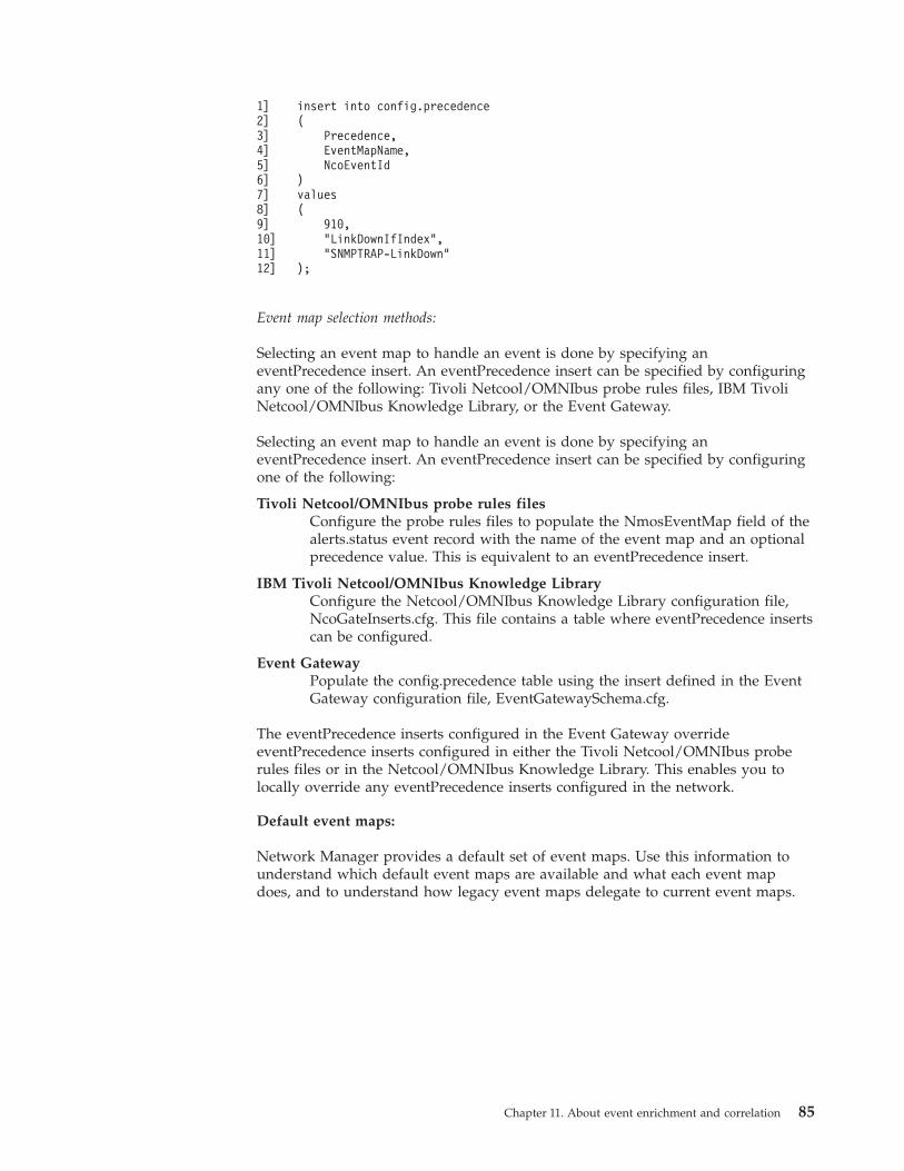
1]2]3]4]5]6]7]8]9]10]11]12]
insert into config.precedence(
Precedence,EventMapName,NcoEventId
)values(
910,"LinkDownIfIndex","SNMPTRAP-LinkDown"
);
Event map selection methods:
Selecting an event map to handle an event is done by specifying aneventPrecedence insert. An eventPrecedence insert can be specified by configuringany one of the following: Tivoli Netcool/OMNIbus probe rules files, IBM TivoliNetcool/OMNIbus Knowledge Library, or the Event Gateway.
Selecting an event map to handle an event is done by specifying aneventPrecedence insert. An eventPrecedence insert can be specified by configuringone of the following:
Tivoli Netcool/OMNIbus probe rules filesConfigure the probe rules files to populate the NmosEventMap field of thealerts.status event record with the name of the event map and an optionalprecedence value. This is equivalent to an eventPrecedence insert.
IBM Tivoli Netcool/OMNIbus Knowledge LibraryConfigure the Netcool/OMNIbus Knowledge Library configuration file,NcoGateInserts.cfg. This file contains a table where eventPrecedence insertscan be configured.
Event GatewayPopulate the config.precedence table using the insert defined in the EventGateway configuration file, EventGatewaySchema.cfg.
The eventPrecedence inserts configured in the Event Gateway overrideeventPrecedence inserts configured in either the Tivoli Netcool/OMNIbus proberules files or in the Netcool/OMNIbus Knowledge Library. This enables you tolocally override any eventPrecedence inserts configured in the network.
Default event maps:
Network Manager provides a default set of event maps. Use this information tounderstand which default event maps are available and what each event mapdoes, and to understand how legacy event maps delegate to current event maps.
Chapter 11. About event enrichment and correlation 85
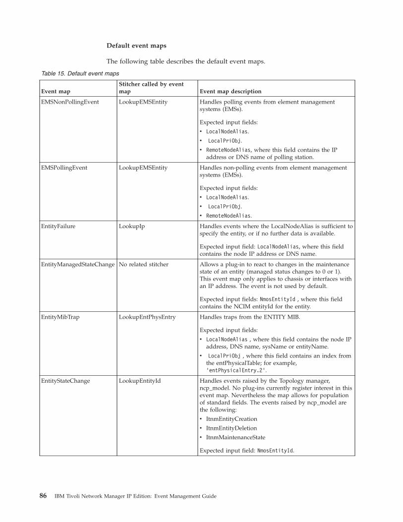
Default event maps
The following table describes the default event maps.
Table 15. Default event maps
Event mapStitcher called by eventmap Event map description
EMSNonPollingEvent LookupEMSEntity Handles polling events from element managementsystems (EMSs).
Expected input fields:
v LocalNodeAlias.
v LocalPriObj.
v RemoteNodeAlias, where this field contains the IPaddress or DNS name of polling station.
EMSPollingEvent LookupEMSEntity Handles non-polling events from element managementsystems (EMSs).
Expected input fields:
v LocalNodeAlias.
v LocalPriObj.
v RemoteNodeAlias.
EntityFailure LookupIp Handles events where the LocalNodeAlias is sufficient tospecify the entity, or if no further data is available.
Expected input field: LocalNodeAlias, where this fieldcontains the node IP address or DNS name.
EntityManagedStateChange No related stitcher Allows a plug-in to react to changes in the maintenancestate of an entity (managed status changes to 0 or 1).This event map only applies to chassis or interfaces withan IP address. The event is not used by default.
Expected input fields: NmosEntityId , where this fieldcontains the NCIM entityId for the entity.
EntityMibTrap LookupEntPhysEntry Handles traps from the ENTITY MIB.
Expected input fields:
v LocalNodeAlias , where this field contains the node IPaddress, DNS name, sysName or entityName.
v LocalPriObj , where this field contains an index fromthe entPhysicalTable; for example,’entPhysicalEntry.2’.
EntityStateChange LookupEntityId Handles events raised by the Topology manager,ncp_model. No plug-ins currently register interest in thisevent map. Nevertheless the map allows for populationof standard fields. The events raised by ncp_model arethe following:
v ItnmEntityCreation
v ItnmEntityDeletion
v ItnmMaintenanceState
Expected input field: NmosEntityId.
86 IBM Tivoli Network Manager IP Edition: Event Management Guide
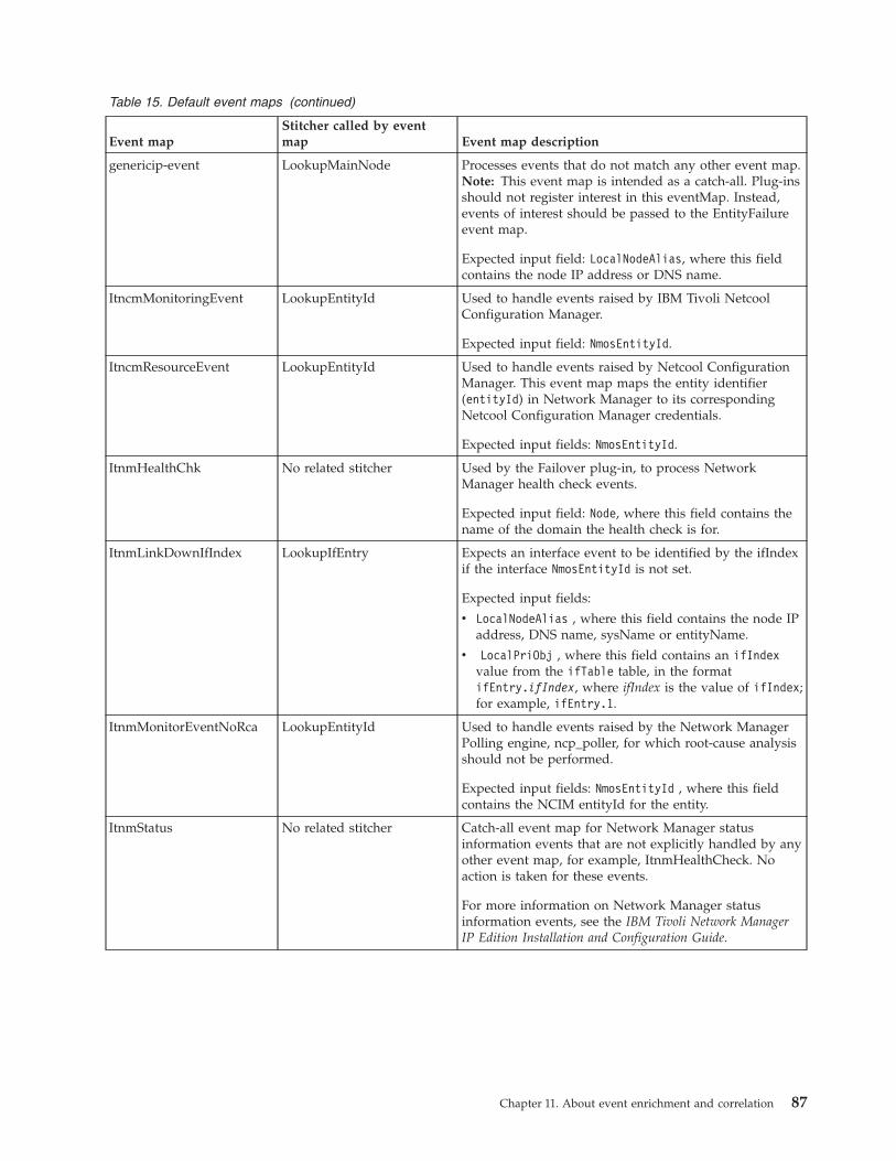
Table 15. Default event maps (continued)
Event mapStitcher called by eventmap Event map description
genericip-event LookupMainNode Processes events that do not match any other event map.Note: This event map is intended as a catch-all. Plug-insshould not register interest in this eventMap. Instead,events of interest should be passed to the EntityFailureevent map.
Expected input field: LocalNodeAlias, where this fieldcontains the node IP address or DNS name.
ItncmMonitoringEvent LookupEntityId Used to handle events raised by IBM Tivoli NetcoolConfiguration Manager.
Expected input field: NmosEntityId.
ItncmResourceEvent LookupEntityId Used to handle events raised by Netcool ConfigurationManager. This event map maps the entity identifier(entityId) in Network Manager to its correspondingNetcool Configuration Manager credentials.
Expected input fields: NmosEntityId.
ItnmHealthChk No related stitcher Used by the Failover plug-in, to process NetworkManager health check events.
Expected input field: Node, where this field contains thename of the domain the health check is for.
ItnmLinkDownIfIndex LookupIfEntry Expects an interface event to be identified by the ifIndexif the interface NmosEntityId is not set.
Expected input fields:
v LocalNodeAlias , where this field contains the node IPaddress, DNS name, sysName or entityName.
v LocalPriObj , where this field contains an ifIndexvalue from the ifTable table, in the formatifEntry.ifIndex, where ifIndex is the value of ifIndex;for example, ifEntry.1.
ItnmMonitorEventNoRca LookupEntityId Used to handle events raised by the Network ManagerPolling engine, ncp_poller, for which root-cause analysisshould not be performed.
Expected input fields: NmosEntityId , where this fieldcontains the NCIM entityId for the entity.
ItnmStatus No related stitcher Catch-all event map for Network Manager statusinformation events that are not explicitly handled by anyother event map, for example, ItnmHealthCheck. Noaction is taken for these events.
For more information on Network Manager statusinformation events, see the IBM Tivoli Network ManagerIP Edition Installation and Configuration Guide.
Chapter 11. About event enrichment and correlation 87
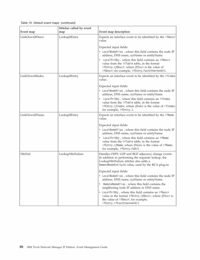
Table 15. Default event maps (continued)
Event mapStitcher called by eventmap Event map description
LinkDownIfDescr LookupIfEntry Expects an interface event to be identified by the ifDescrvalue.
Expected input fields:
v LocalNodeAlias , where this field contains the node IPaddress, DNS name, sysName or entityName.
v LocalPriObj , where this field contains an ifDescrvalue from the ifTable table, in the formatifEntry.ifDescr, where ifDescr is the value ofifDescr; for example, ifEntry.FastEthernet0/1.
LinkDownIfIndex LookupIfEntry Expects an interface event to be identified by the ifIndexvalue.
Expected input fields:
v LocalNodeAlias , where this field contains the node IPaddress, DNS name, sysName or entityName.
v LocalPriObj , where this field contains an ifIndexvalue from the ifTable table, in the formatifEntry.ifIndex, where ifIndex is the value of ifIndex;for example, ifEntry.1.
LinkDownIfName LookupIfEntry Expects an interface event to be identified by the ifNamevalue.
Expected input fields:
v LocalNodeAlias , where this field contains the node IPaddress, DNS name, sysName or entityName.
v LocalPriObj , where this field contains an ifNamevalue from the ifTable table, in the formatifEntry.ifName, where ifName is the value of ifName;for example, ifEntry.Fa0/1.
NbrFail LookupNbrFailure Handles OSPF, LDP and BGP adjacency change events.In addition to performing the requisite lookup, theLookupNbrFailure stitcher also adds aRemoteNodeEntityId value, used by the RCA plug-in.
Expected input fields:
v LocalNodeAlias , where this field contains the node IPaddress, DNS name, sysName or entityName.
v RemoteNodeAlias , where this field contains theneighboring node IP address or DNS name.
v LocalPriObj , where this field contains an ifDescrvalue in the format ifEntry.ifDescr, where ifDescr isthe value of ifDescr; for example,ifEntry.ifFastEthernet0/1.
88 IBM Tivoli Network Manager IP Edition: Event Management Guide
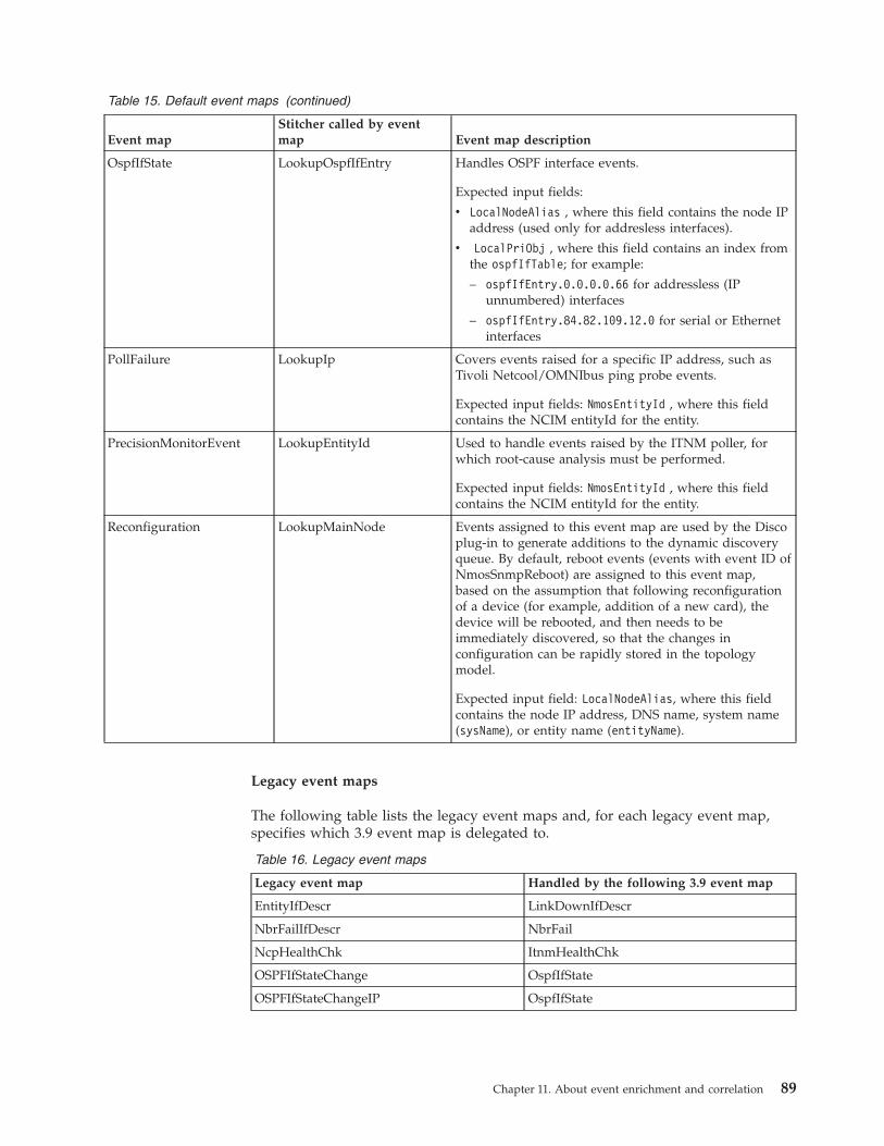
Table 15. Default event maps (continued)
Event mapStitcher called by eventmap Event map description
OspfIfState LookupOspfIfEntry Handles OSPF interface events.
Expected input fields:
v LocalNodeAlias , where this field contains the node IPaddress (used only for addresless interfaces).
v LocalPriObj , where this field contains an index fromthe ospfIfTable; for example:
– ospfIfEntry.0.0.0.0.66 for addressless (IPunnumbered) interfaces
– ospfIfEntry.84.82.109.12.0 for serial or Ethernetinterfaces
PollFailure LookupIp Covers events raised for a specific IP address, such asTivoli Netcool/OMNIbus ping probe events.
Expected input fields: NmosEntityId , where this fieldcontains the NCIM entityId for the entity.
PrecisionMonitorEvent LookupEntityId Used to handle events raised by the ITNM poller, forwhich root-cause analysis must be performed.
Expected input fields: NmosEntityId , where this fieldcontains the NCIM entityId for the entity.
Reconfiguration LookupMainNode Events assigned to this event map are used by the Discoplug-in to generate additions to the dynamic discoveryqueue. By default, reboot events (events with event ID ofNmosSnmpReboot) are assigned to this event map,based on the assumption that following reconfigurationof a device (for example, addition of a new card), thedevice will be rebooted, and then needs to beimmediately discovered, so that the changes inconfiguration can be rapidly stored in the topologymodel.
Expected input field: LocalNodeAlias, where this fieldcontains the node IP address, DNS name, system name(sysName), or entity name (entityName).
Legacy event maps
The following table lists the legacy event maps and, for each legacy event map,specifies which 3.9 event map is delegated to.
Table 16. Legacy event maps
Legacy event map Handled by the following 3.9 event map
EntityIfDescr LinkDownIfDescr
NbrFailIfDescr NbrFail
NcpHealthChk ItnmHealthChk
OSPFIfStateChange OspfIfState
OSPFIfStateChangeIP OspfIfState
Chapter 11. About event enrichment and correlation 89
How legacy event maps delegate to 3.9 event maps
This example explains how the NbrFailIfDescr legacy event map delegates to theNbrFail 3.9 event map.1. An event is received that has an eventId listed in the config.precedence table,
mapping to the NbrFailIfDescr eventMap.2. The NbrFailIfDescr eventMap delegates to the NbrFail eventMap, using the
HandledBy field.3. The event is treated exactly as if it had been mapped to the NbrFail eventMap
in the first place, that is it will be handled as follows:v The LookupNbrFailure stitcher is called. This stitcher is referenced in the
Stitcher field relevant to the NbrFail event map entry in theconfig.eventMaps table.
v The fields of the NbrFail eventMap (not the NbrFailIfDescr to which theevent was originally mapped) are appended to the event before passing it toplug-ins.
v Plugins that have registered interest in the NbrFail eventMap (not theNbrFailIfDescr to which the event was originally mapped) receive the event.
In this example, the flexibility of the stitcher language allows both types of eventto be handled in the same way. If the ifDescr, expected by the legacyNbrFailIfDescr eventMap, is available, it is extracted and used within theLookupNbrFailure stitcher.Related concepts:Appendix F, “Network Manager event categories,” on page 193The events that are raised by Network Manager fall into two categories: eventsabout the network being monitored and events about Network Manager processes.
Event Gateway stitchersEvent Gateway stitchers match events to an entity, perform a topology lookup, andthen use the topology data retrieved to enrich the event data.
Event Gateway stitchers are stored in the following location: $NCHOME/precision/eventGateway/stitchers/.
For information on stitcher language, see the IBM Tivoli Network Manager IP EditionLanguage Reference.
There are four types of Event Gateway stitcher:v “Topology lookup stitchers” on page 93v “Data extraction stitchers” on page 97v “Entity retrieval stitchers” on page 98v “Event enrichment stitchers” on page 100
In addition, a number of Event Gateway stitchers are provided that are not usedby default. These stitchers are provided as examples of extra functionality that canbe added to the Event Gateway using stitchers. For more information, see“Stitchers not used by default” on page 102.
90 IBM Tivoli Network Manager IP Edition: Event Management Guide
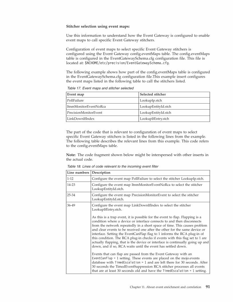
Stitcher selection using event maps:
Use this information to understand how the Event Gateway is configured to enableevent maps to call specific Event Gateway stitchers.
Configuration of event maps to select specific Event Gateway stitchers isconfigured using the Event Gateway config.eventMaps table. The config.eventMapstable is configured in the EventGatewaySchema.cfg configuration file. This file islocated at: $NCHOME/etc/precision/EventGatewaySchema.cfg.
The following example shows how part of the config.eventMaps table is configuredin the EventGatewaySchema.cfg configuration file.This example insert configuresthe event maps listed in the following table to call the stitchers listed.
Table 17. Event maps and stitcher selected
Event map Selected stitcher
PollFailure LookupIp.stch
ItnmMonitorEventNoRca LookupEntityId.stch
PrecisionMonitorEvent LookupEntityId.stch
LinkDownIfIndex LookupIfEntry.stch
The part of the code that is relevant to configuration of event maps to selectspecific Event Gateway stitchers is listed in the following lines from the example.The following table describes the relevant lines from this example. This code refersto the config.eventMaps table.
Note: The code fragment shown below might be interspersed with other inserts inthe actual code.
Table 18. Lines of code relevant to the incoming event filter
Line numbers Description
1-12 Configure the event map PollFailure to select the stitcher LookupIp.stch.
14-23 Configure the event map ItnmMonitorEventNoRca to select the stitcherLookupEntityId.stch.
25-34 Configure the event map PrecisionMonitorEvent to select the stitcherLookupEntityId.stch.
36-49 Configure the event map LinkDownIfIndex to select the stitcherLookupIfEntry.stch.
As this is a trap event, it is possible for the event to flap. Flapping is acondition where a device or interface connects to and then disconnectsfrom the network repeatedly in a short space of time. This causes problemand clear events to be received one after the other for the same device orinterface. Setting the EventCanFlap flag to 1 informs the RCA plug-in ofthis condition. The RCA plug-in checks if events with this flag set to 1 areactually flapping, that is the device or interface is continually going up anddown, and if so, RCA waits until the event has settled down.
Events that can flap are passed from the Event Gateway with anEventCanFlap = 1 setting. These events are placed on the mojo.eventsdatabase with TimedEscalation = 1 and are left there for 30 seconds. After30 seconds the TimedEventSuppression RCA stitcher processes all eventsthat are at least 30 seconds old and have the TimedEscalation = 1 setting.
Chapter 11. About event enrichment and correlation 91
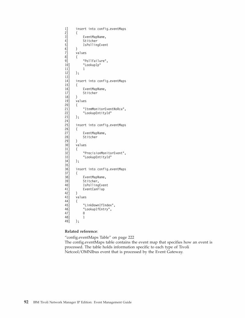
1]2]3]4]5]6]7]8]9]10]11]12]13]14]15]16]17]18]19]20]21]22]23]24]25]26]27]28]29]30]31]32]33]34]35]36]37]38]39]40]41]42]43]44]45]46]47]48]49]
insert into config.eventMaps(
EventMapName,StitcherIsPollingEvent
)values(
"PollFailure","LookupIp"1
);
insert into config.eventMaps(
EventMapName,Stitcher
)values(
"ItnmMonitorEventNoRca","LookupEntityId"
);
insert into config.eventMaps(
EventMapName,Stitcher
)values(
"PrecisionMonitorEvent","LookupEntityId"
);
insert into config.eventMaps(
EventMapName,Stitcher,IsPollingEventEventCanFlap
)values(
"LinkDownIfIndex","LookupIfEntry",01
);
Related reference:“config.eventMaps Table” on page 222The config.eventMaps table contains the event map that specifies how an event isprocessed. The table holds information specific to each type of TivoliNetcool/OMNIbus event that is processed by the Event Gateway.
92 IBM Tivoli Network Manager IP Edition: Event Management Guide
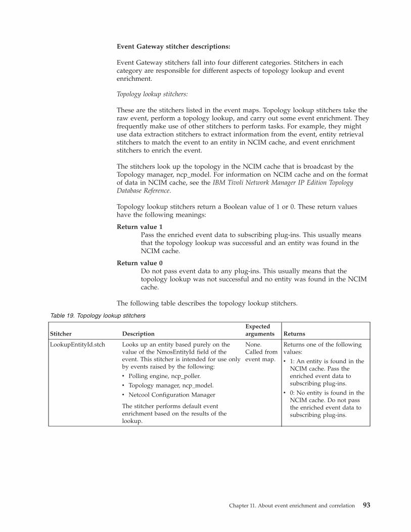
Event Gateway stitcher descriptions:
Event Gateway stitchers fall into four different categories. Stitchers in eachcategory are responsible for different aspects of topology lookup and eventenrichment.
Topology lookup stitchers:
These are the stitchers listed in the event maps. Topology lookup stitchers take theraw event, perform a topology lookup, and carry out some event enrichment. Theyfrequently make use of other stitchers to perform tasks. For example, they mightuse data extraction stitchers to extract information from the event, entity retrievalstitchers to match the event to an entity in NCIM cache, and event enrichmentstitchers to enrich the event.
The stitchers look up the topology in the NCIM cache that is broadcast by theTopology manager, ncp_model. For information on NCIM cache and on the formatof data in NCIM cache, see the IBM Tivoli Network Manager IP Edition TopologyDatabase Reference.
Topology lookup stitchers return a Boolean value of 1 or 0. These return valueshave the following meanings:
Return value 1Pass the enriched event data to subscribing plug-ins. This usually meansthat the topology lookup was successful and an entity was found in theNCIM cache.
Return value 0Do not pass event data to any plug-ins. This usually means that thetopology lookup was not successful and no entity was found in the NCIMcache.
The following table describes the topology lookup stitchers.
Table 19. Topology lookup stitchers
Stitcher DescriptionExpectedarguments Returns
LookupEntityId.stch Looks up an entity based purely on thevalue of the NmosEntityId field of theevent. This stitcher is intended for use onlyby events raised by the following:
v Polling engine, ncp_poller.
v Topology manager, ncp_model.
v Netcool Configuration Manager
The stitcher performs default eventenrichment based on the results of thelookup.
None.Called fromevent map.
Returns one of the followingvalues:
v 1: An entity is found in theNCIM cache. Pass theenriched event data tosubscribing plug-ins.
v 0: No entity is found in theNCIM cache. Do not passthe enriched event data tosubscribing plug-ins.
Chapter 11. About event enrichment and correlation 93
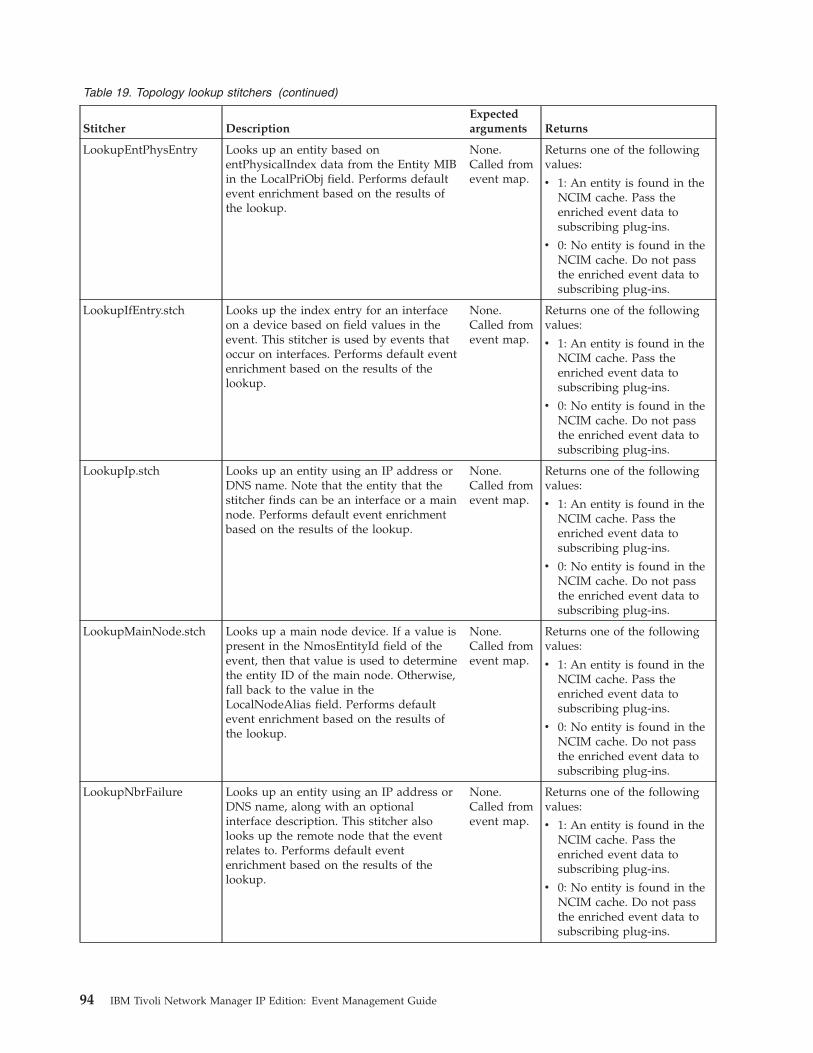
Table 19. Topology lookup stitchers (continued)
Stitcher DescriptionExpectedarguments Returns
LookupEntPhysEntry Looks up an entity based onentPhysicalIndex data from the Entity MIBin the LocalPriObj field. Performs defaultevent enrichment based on the results ofthe lookup.
None.Called fromevent map.
Returns one of the followingvalues:
v 1: An entity is found in theNCIM cache. Pass theenriched event data tosubscribing plug-ins.
v 0: No entity is found in theNCIM cache. Do not passthe enriched event data tosubscribing plug-ins.
LookupIfEntry.stch Looks up the index entry for an interfaceon a device based on field values in theevent. This stitcher is used by events thatoccur on interfaces. Performs default eventenrichment based on the results of thelookup.
None.Called fromevent map.
Returns one of the followingvalues:
v 1: An entity is found in theNCIM cache. Pass theenriched event data tosubscribing plug-ins.
v 0: No entity is found in theNCIM cache. Do not passthe enriched event data tosubscribing plug-ins.
LookupIp.stch Looks up an entity using an IP address orDNS name. Note that the entity that thestitcher finds can be an interface or a mainnode. Performs default event enrichmentbased on the results of the lookup.
None.Called fromevent map.
Returns one of the followingvalues:
v 1: An entity is found in theNCIM cache. Pass theenriched event data tosubscribing plug-ins.
v 0: No entity is found in theNCIM cache. Do not passthe enriched event data tosubscribing plug-ins.
LookupMainNode.stch Looks up a main node device. If a value ispresent in the NmosEntityId field of theevent, then that value is used to determinethe entity ID of the main node. Otherwise,fall back to the value in theLocalNodeAlias field. Performs defaultevent enrichment based on the results ofthe lookup.
None.Called fromevent map.
Returns one of the followingvalues:
v 1: An entity is found in theNCIM cache. Pass theenriched event data tosubscribing plug-ins.
v 0: No entity is found in theNCIM cache. Do not passthe enriched event data tosubscribing plug-ins.
LookupNbrFailure Looks up an entity using an IP address orDNS name, along with an optionalinterface description. This stitcher alsolooks up the remote node that the eventrelates to. Performs default eventenrichment based on the results of thelookup.
None.Called fromevent map.
Returns one of the followingvalues:
v 1: An entity is found in theNCIM cache. Pass theenriched event data tosubscribing plug-ins.
v 0: No entity is found in theNCIM cache. Do not passthe enriched event data tosubscribing plug-ins.
94 IBM Tivoli Network Manager IP Edition: Event Management Guide
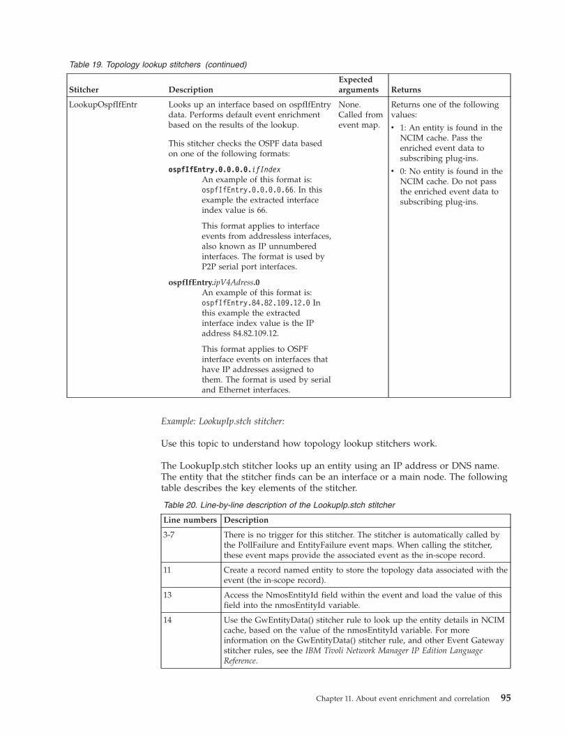
Table 19. Topology lookup stitchers (continued)
Stitcher DescriptionExpectedarguments Returns
LookupOspfIfEntr Looks up an interface based on ospfIfEntrydata. Performs default event enrichmentbased on the results of the lookup.
This stitcher checks the OSPF data basedon one of the following formats:
ospfIfEntry.0.0.0.0.ifIndexAn example of this format is:ospfIfEntry.0.0.0.0.66. In thisexample the extracted interfaceindex value is 66.
This format applies to interfaceevents from addressless interfaces,also known as IP unnumberedinterfaces. The format is used byP2P serial port interfaces.
ospfIfEntry.ipV4Adress.0An example of this format is:ospfIfEntry.84.82.109.12.0 Inthis example the extractedinterface index value is the IPaddress 84.82.109.12.
This format applies to OSPFinterface events on interfaces thathave IP addresses assigned tothem. The format is used by serialand Ethernet interfaces.
None.Called fromevent map.
Returns one of the followingvalues:
v 1: An entity is found in theNCIM cache. Pass theenriched event data tosubscribing plug-ins.
v 0: No entity is found in theNCIM cache. Do not passthe enriched event data tosubscribing plug-ins.
Example: LookupIp.stch stitcher:
Use this topic to understand how topology lookup stitchers work.
The LookupIp.stch stitcher looks up an entity using an IP address or DNS name.The entity that the stitcher finds can be an interface or a main node. The followingtable describes the key elements of the stitcher.
Table 20. Line-by-line description of the LookupIp.stch stitcher
Line numbers Description
3-7 There is no trigger for this stitcher. The stitcher is automatically called bythe PollFailure and EntityFailure event maps. When calling the stitcher,these event maps provide the associated event as the in-scope record.
11 Create a record named entity to store the topology data associated with theevent (the in-scope record).
13 Access the NmosEntityId field within the event and load the value of thisfield into the nmosEntityId variable.
14 Use the GwEntityData() stitcher rule to look up the entity details in NCIMcache, based on the value of the nmosEntityId variable. For moreinformation on the GwEntityData() stitcher rule, and other Event Gatewaystitcher rules, see the IBM Tivoli Network Manager IP Edition LanguageReference.
Chapter 11. About event enrichment and correlation 95
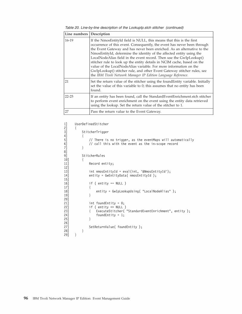
Table 20. Line-by-line description of the LookupIp.stch stitcher (continued)
Line numbers Description
16-19 If the NmosEntityId field is NULL, this means that this is the firstoccurrence of this event. Consequently, the event has never been throughthe Event Gateway and has never been enriched. As an alternative to theNmosEntityId, determine the identity of the affected entity using theLocalNodeAlias field in the event record. Then use the GwIpLookup()stitcher rule to look up the entity details in NCIM cache, based on thevalue of the LocalNodeAlias variable. For more information on theGwIpLookup() stitcher rule, and other Event Gateway stitcher rules, seethe IBM Tivoli Network Manager IP Edition Language Reference.
21 Set the return value of the stitcher using the foundEntity variable. Initiallyset the value of this variable to 0; this assumes that no entity has beenfound.
22-25 If an entity has been found, call the StandardEventEnrichment.stch stitcherto perform event enrichment on the event using the entity data retrievedusing the lookup. Set the return value of the stitcher to 1.
27 Pass the return value to the Event Gateway.
1]2]3]4]5]6]7]8]9]10]11]12]13]14]15]16]17]18]19]20]21]22]23]24]25]26]27]28]29]
UserDefinedStitcher{
StitcherTrigger{
// There is no trigger, as the eventMaps will automatically// call this with the event as the in-scope record
}
StitcherRules{
Record entity;
int nmosEntityId = eval(int, ’&NmosEntityId’);entity = GwEntityData( nmosEntityId );
if ( entity == NULL ){
entity = GwIpLookupUsing( "LocalNodeAlias" );}
int foundEntity = 0;if ( entity <> NULL ){ ExecuteStitcher( "StandardEventEnrichment", entity );
foundEntity = 1;}
SetReturnValue( foundEntity );}
}
96 IBM Tivoli Network Manager IP Edition: Event Management Guide
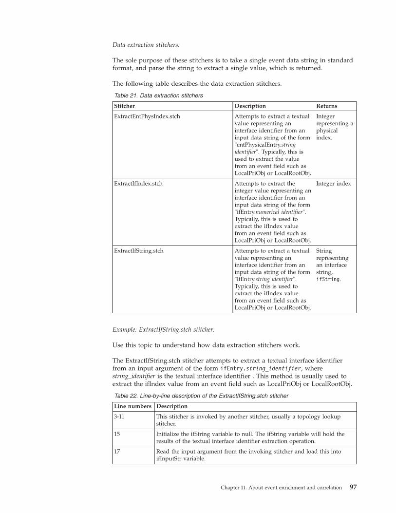
Data extraction stitchers:
The sole purpose of these stitchers is to take a single event data string in standardformat, and parse the string to extract a single value, which is returned.
The following table describes the data extraction stitchers.
Table 21. Data extraction stitchers
Stitcher Description Returns
ExtractEntPhysIndex.stch Attempts to extract a textualvalue representing aninterface identifier from aninput data string of the form"entPhysicalEntry.stringidentifier". Typically, this isused to extract the valuefrom an event field such asLocalPriObj or LocalRootObj.
Integerrepresenting aphysicalindex.
ExtractIfIndex.stch Attempts to extract theinteger value representing aninterface identifier from aninput data string of the form"ifEntry.numerical identifier".Typically, this is used toextract the ifIndex valuefrom an event field such asLocalPriObj or LocalRootObj.
Integer index
ExtractIfString.stch Attempts to extract a textualvalue representing aninterface identifier from aninput data string of the form"ifEntry.string identifier".Typically, this is used toextract the ifIndex valuefrom an event field such asLocalPriObj or LocalRootObj.
Stringrepresentingan interfacestring,ifString.
Example: ExtractIfString.stch stitcher:
Use this topic to understand how data extraction stitchers work.
The ExtractIfString.stch stitcher attempts to extract a textual interface identifierfrom an input argument of the form ifEntry.string_identifier, wherestring_identifier is the textual interface identifier . This method is usually used toextract the ifIndex value from an event field such as LocalPriObj or LocalRootObj.
Table 22. Line-by-line description of the ExtractIfString.stch stitcher
Line numbers Description
3-11 This stitcher is invoked by another stitcher, usually a topology lookupstitcher.
15 Initialize the ifString variable to null. The ifString variable will hold theresults of the textual interface identifier extraction operation.
17 Read the input argument from the invoking stitcher and load this intoifInputStr variable.
Chapter 11. About event enrichment and correlation 97
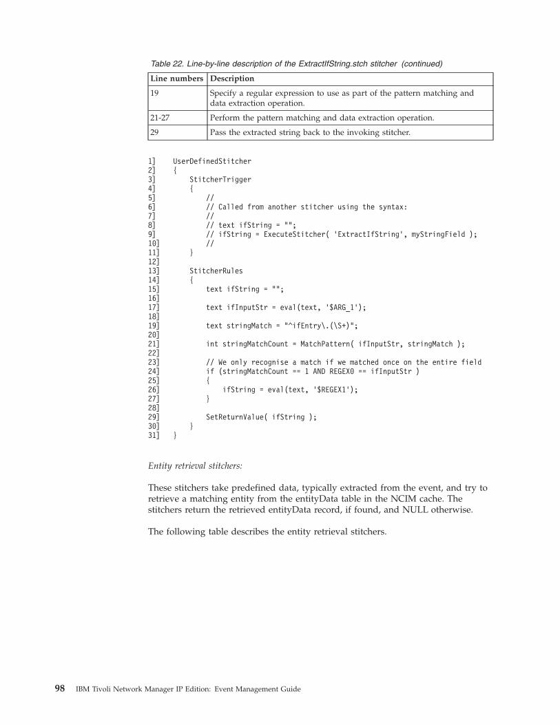
Table 22. Line-by-line description of the ExtractIfString.stch stitcher (continued)
Line numbers Description
19 Specify a regular expression to use as part of the pattern matching anddata extraction operation.
21-27 Perform the pattern matching and data extraction operation.
29 Pass the extracted string back to the invoking stitcher.
1]2]3]4]5]6]7]8]9]10]11]12]13]14]15]16]17]18]19]20]21]22]23]24]25]26]27]28]29]30]31]
UserDefinedStitcher{
StitcherTrigger{
//// Called from another stitcher using the syntax://// text ifString = "";// ifString = ExecuteStitcher( ’ExtractIfString’, myStringField );//
}
StitcherRules{
text ifString = "";
text ifInputStr = eval(text, ’$ARG_1’);
text stringMatch = "^ifEntry\.(\S+)";
int stringMatchCount = MatchPattern( ifInputStr, stringMatch );
// We only recognise a match if we matched once on the entire fieldif (stringMatchCount == 1 AND REGEX0 == ifInputStr ){
ifString = eval(text, ’$REGEX1’);}
SetReturnValue( ifString );}
}
Entity retrieval stitchers:
These stitchers take predefined data, typically extracted from the event, and try toretrieve a matching entity from the entityData table in the NCIM cache. Thestitchers return the retrieved entityData record, if found, and NULL otherwise.
The following table describes the entity retrieval stitchers.
98 IBM Tivoli Network Manager IP Edition: Event Management Guide
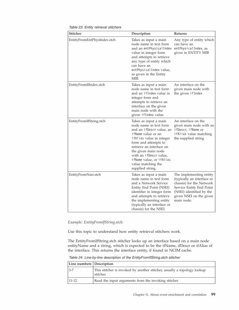
Table 23. Entity retrieval stitchers
Stitcher Description Returns
EntityFromEntPhysIndex.stch Takes as input a mainnode name in text formand an entPhysicalIndexvalue in integer formand attempts to retrieveany type of entity whichcan have anentPhysicalIndex value,as given in the EntityMIB.
Any type of entity whichcan have anentPhysicalIndex, asgiven in ENTITY MIB
EntityFromIfIndex.stch Takes as input a mainnode name in text formand an ifIndex value ininteger form andattempts to retrieve aninterface on the givenmain node with thegiven ifIndex value.
An interface on thegiven main node withthe given ifIndex
EntityFromIfString.stch Takes as input a mainnode name in text formand an ifDescr value, anifName value or anifAlias value in integerform and attempts toretrieve an interface onthe given main nodewith an ifDescr value,ifName value, or ifAliasvalue matching thesupplied string.
An interface on thegiven main node with anifDescr, ifName orifAlias value matchingthe supplied string
EntityFromNsei.stch Takes as input a mainnode name in text formand a Network ServiceEntity End Point (NSEI)identifier in integer formand attempts to retrievethe implementing entity(typically an interface orchassis) for the NSEI.
The implementing entity(typically an interface orchassis) for the NetworkService Entity End Point(NSEI) identified by thegiven NSEI on the givenmain node.
Example: EntityFromIfString.stch:
Use this topic to understand how entity retrieval stitchers work.
The EntityFromIfString.stch stitcher looks up an interface based on a main nodeentityName and a string, which is expected to be the ifName, ifDescr or ifAlias ofthe interface. This returns the interface entity, if found in NCIM cache.
Table 24. Line-by-line description of the EntityFromIfString.stch stitcher
Line numbers Description
3-7 This stitcher is invoked by another stitcher, usually a topology lookupstitcher.
11-12 Read the input arguments from the invoking stitcher.
Chapter 11. About event enrichment and correlation 99
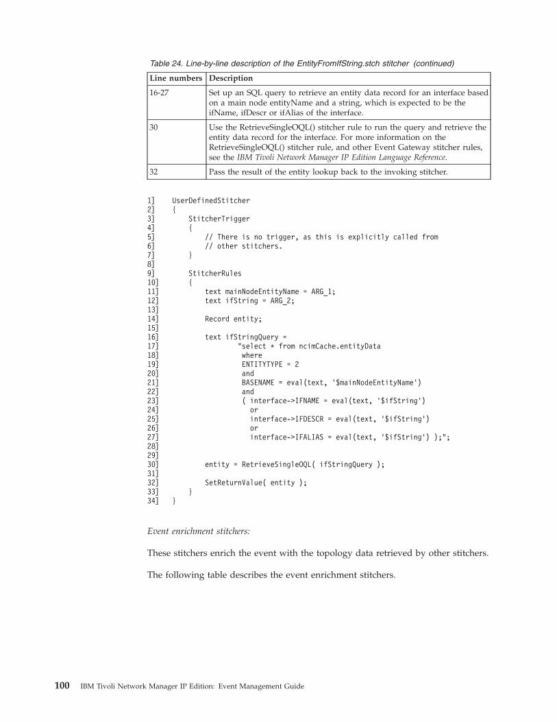
Table 24. Line-by-line description of the EntityFromIfString.stch stitcher (continued)
Line numbers Description
16-27 Set up an SQL query to retrieve an entity data record for an interface basedon a main node entityName and a string, which is expected to be theifName, ifDescr or ifAlias of the interface.
30 Use the RetrieveSingleOQL() stitcher rule to run the query and retrieve theentity data record for the interface. For more information on theRetrieveSingleOQL() stitcher rule, and other Event Gateway stitcher rules,see the IBM Tivoli Network Manager IP Edition Language Reference.
32 Pass the result of the entity lookup back to the invoking stitcher.
1]2]3]4]5]6]7]8]9]10]11]12]13]14]15]16]17]18]19]20]21]22]23]24]25]26]27]28]29]30]31]32]33]34]
UserDefinedStitcher{
StitcherTrigger{
// There is no trigger, as this is explicitly called from// other stitchers.
}
StitcherRules{
text mainNodeEntityName = ARG_1;text ifString = ARG_2;
Record entity;
text ifStringQuery ="select * from ncimCache.entityDatawhereENTITYTYPE = 2andBASENAME = eval(text, ’$mainNodeEntityName’)and( interface->IFNAME = eval(text, ’$ifString’)
orinterface->IFDESCR = eval(text, ’$ifString’)orinterface->IFALIAS = eval(text, ’$ifString’) );";
entity = RetrieveSingleOQL( ifStringQuery );
SetReturnValue( entity );}
}
Event enrichment stitchers:
These stitchers enrich the event with the topology data retrieved by other stitchers.
The following table describes the event enrichment stitchers.
100 IBM Tivoli Network Manager IP Edition: Event Management Guide
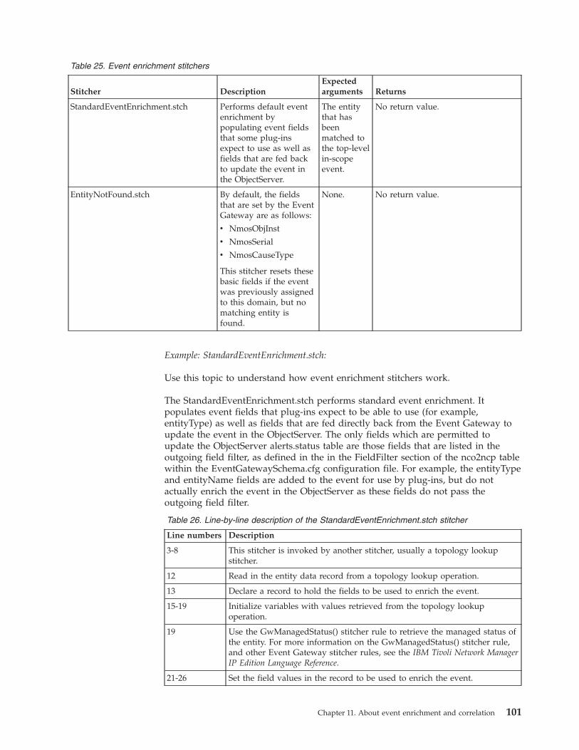
Table 25. Event enrichment stitchers
Stitcher DescriptionExpectedarguments Returns
StandardEventEnrichment.stch Performs default eventenrichment bypopulating event fieldsthat some plug-insexpect to use as well asfields that are fed backto update the event inthe ObjectServer.
The entitythat hasbeenmatched tothe top-levelin-scopeevent.
No return value.
EntityNotFound.stch By default, the fieldsthat are set by the EventGateway are as follows:
v NmosObjInst
v NmosSerial
v NmosCauseType
This stitcher resets thesebasic fields if the eventwas previously assignedto this domain, but nomatching entity isfound.
None. No return value.
Example: StandardEventEnrichment.stch:
Use this topic to understand how event enrichment stitchers work.
The StandardEventEnrichment.stch performs standard event enrichment. Itpopulates event fields that plug-ins expect to be able to use (for example,entityType) as well as fields that are fed directly back from the Event Gateway toupdate the event in the ObjectServer. The only fields which are permitted toupdate the ObjectServer alerts.status table are those fields that are listed in theoutgoing field filter, as defined in the in the FieldFilter section of the nco2ncp tablewithin the EventGatewaySchema.cfg configuration file. For example, the entityTypeand entityName fields are added to the event for use by plug-ins, but do notactually enrich the event in the ObjectServer as these fields do not pass theoutgoing field filter.
Table 26. Line-by-line description of the StandardEventEnrichment.stch stitcher
Line numbers Description
3-8 This stitcher is invoked by another stitcher, usually a topology lookupstitcher.
12 Read in the entity data record from a topology lookup operation.
13 Declare a record to hold the fields to be used to enrich the event.
15-19 Initialize variables with values retrieved from the topology lookupoperation.
19 Use the GwManagedStatus() stitcher rule to retrieve the managed status ofthe entity. For more information on the GwManagedStatus() stitcher rule,and other Event Gateway stitcher rules, see the IBM Tivoli Network ManagerIP Edition Language Reference.
21-26 Set the field values in the record to be used to enrich the event.
Chapter 11. About event enrichment and correlation 101
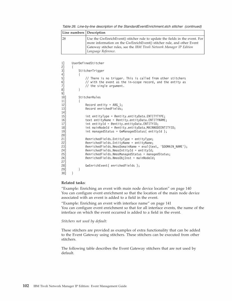
Table 26. Line-by-line description of the StandardEventEnrichment.stch stitcher (continued)
Line numbers Description
28 Use the GwEnrichEvent() stitcher rule to update the fields in the event. Formore information on the GwEnrichEvent() stitcher rule, and other EventGateway stitcher rules, see the IBM Tivoli Network Manager IP EditionLanguage Reference.
1]2]3]4]5]6]7]8]9]10]11]12]13]14]15]16]17]18]19]20]21]22]23]24]25]26]27]28]29]30]
UserDefinedStitcher{
StitcherTrigger{
// There is no trigger. This is called from other stitchers// with the event as the in-scope record, and the entity as// the single argument.
}
StitcherRules{
Record entity = ARG_1;Record enrichedFields;
int entityType = @entity.entityData.ENTITYTYPE;text entityName = @entity.entityData.ENTITYNAME;int entityId = @entity.entityData.ENTITYID;int mainNodeId = @entity.entityData.MAINNODEENTITYID;int managedStatus = GwManagedStatus( entityId );
@enrichedFields.EntityType = entityType;@enrichedFields.EntityName = entityName;@enrichedFields.NmosDomainName = eval(text, ’$DOMAIN_NAME’);@enrichedFields.NmosEntityId = entityId;@enrichedFields.NmosManagedStatus = managedStatus;@enrichedFields.NmosObjInst = mainNodeId;
GwEnrichEvent( enrichedFields );}
}
Related tasks:“Example: Enriching an event with main node device location” on page 140You can configure event enrichment so that the location of the main node deviceassociated with an event is added to a field in the event.“Example: Enriching an event with interface name” on page 141You can configure event enrichment so that for all interface events, the name of theinterface on which the event occurred is added to a field in the event.
Stitchers not used by default:
These stitchers are provided as examples of extra functionality that can be addedto the Event Gateway using stitchers. These stitchers can be executed from otherstitchers.
The following table describes the Event Gateway stitchers that are not used bydefault.
102 IBM Tivoli Network Manager IP Edition: Event Management Guide
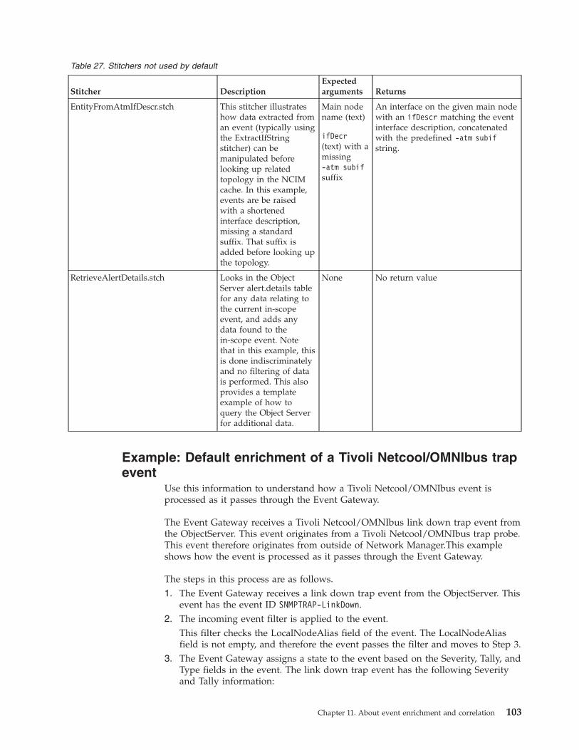
Table 27. Stitchers not used by default
Stitcher DescriptionExpectedarguments Returns
EntityFromAtmIfDescr.stch This stitcher illustrateshow data extracted froman event (typically usingthe ExtractIfStringstitcher) can bemanipulated beforelooking up relatedtopology in the NCIMcache. In this example,events are be raisedwith a shortenedinterface description,missing a standardsuffix. That suffix isadded before looking upthe topology.
Main nodename (text)
ifDecr(text) with amissing-atm subifsuffix
An interface on the given main nodewith an ifDescr matching the eventinterface description, concatenatedwith the predefined -atm subifstring.
RetrieveAlertDetails.stch Looks in the ObjectServer alert.details tablefor any data relating tothe current in-scopeevent, and adds anydata found to thein-scope event. Notethat in this example, thisis done indiscriminatelyand no filtering of datais performed. This alsoprovides a templateexample of how toquery the Object Serverfor additional data.
None No return value
Example: Default enrichment of a Tivoli Netcool/OMNIbus trapevent
Use this information to understand how a Tivoli Netcool/OMNIbus event isprocessed as it passes through the Event Gateway.
The Event Gateway receives a Tivoli Netcool/OMNIbus link down trap event fromthe ObjectServer. This event originates from a Tivoli Netcool/OMNIbus trap probe.This event therefore originates from outside of Network Manager.This exampleshows how the event is processed as it passes through the Event Gateway.
The steps in this process are as follows.1. The Event Gateway receives a link down trap event from the ObjectServer. This
event has the event ID SNMPTRAP-LinkDown.2. The incoming event filter is applied to the event.
This filter checks the LocalNodeAlias field of the event. The LocalNodeAliasfield is not empty, and therefore the event passes the filter and moves to Step 3.
3. The Event Gateway assigns a state to the event based on the Severity, Tally, andType fields in the event. The link down trap event has the following Severityand Tally information:
Chapter 11. About event enrichment and correlation 103
v Severity is non-zerov Tally is 1v Type is 'Problem'Based in this information, the Event Gateway assigns the Occurred state to thisevent. This is a problem event and is a candidate for RCA.
4. The default incoming field filter is applied to the event. This field filter filtersout alerts.status fields that do not participate in the Event Gateway processingand only allows the following fields through:v Acknowledgedv AlertGroupv EventIdv FirstOccurrencev LastOccurrencev LocalNodeAliasv LocalPriObjv LocalRootObjv Managerv NmosCauseTypev NmosDomainNamev NmosEntityIdv NmosEventMapv NmosManagedStatusv NmosObjInstv NmosSerialv Nodev RemoteNodeAliasv EventIdv Serialv ServerNamev Severityv Summaryv SuppressEsclv Tallyv Type
5. The Event Gateway determines how to handle this event, by determiningwhich event map to use. Event maps define how to handle an event. At thesame time a numerical precedence value is associated with the event.The event in this example has event ID SNMPTRAP-LinkDown. The insert thatdefines how to handle events with this event ID is defined in theNetcool/OMNIbus Knowledge Library configuration file, NcoGateInserts.cfg,and has the following form.insert into config.precedence(
Precedence,EventMapName,NcoEventId
)values(
104 IBM Tivoli Network Manager IP Edition: Event Management Guide
910,"LinkDownIfIndex","SNMPTRAP-LinkDown"
);
This insert instructs the Event Gateway to handle the SNMP link down trapevent as follows:v Apply the event map LinkDownIfIndex to the event.
– This event map covers link up and link down events from the TivoliNetcool/OMNIbus mttrapd probe These events all use the ifIndex valueheld in the LocalPriObj field of alerts.status to identify the interface fromwhich this trap originated.
– The RCA plug-in subscribes to events that are handled by theLinkDownIfIndex event map. Consequently this event will be passed tothe RCA plug-in.
v When sending the event for RCA, use a precedence value of 910 for theevent.
6. The Event Gateway uses the selected event map to determine which stitcher tocall to perform a topology lookup.The selected event map is LinkDownIfIndex. In the EventGatewaySchema.cfgconfiguration file, the following insert is associated with this event map:insert into config.eventMaps(
EventMapName,Stitcher,EventCanFlap
)values(
"LinkDownIfIndex","LookupIfEntry",1
);
This insert instructs the Event Gateway to perform the following actions:v Use the stitcher LookupIfEntry to perform the topology lookup.
The LookupIfEntry looks up the index entry for an interface on a devicebased on the field values in the event. Based on the value of the interfaceindex extracted from the fields in the event, the stitcher retrieves a row fromthe NCIM cache consisting of entity and interface data. Another stitcher iscalled to perform event enrichment.
v Set the EventCanFlap flag to 1 to inform the RCA plug-in that the relateddevice or interface might be continuing going up and down.
7. Enriched event data is filtered by the outgoing field filter and placed on theEvent Gateway queue.
8. The event is passed to the RCA plug-in.9. Following further event enrichment by RCA, the event is placed on the Event
Gateway queue.Related concepts:“Quick reference for event enrichment” on page 71Use this information to understand how an event is processed as it passes throughthe Event Gateway.
Chapter 11. About event enrichment and correlation 105
Event Gateway pluginsEvent Gateway plug-ins are modules of the Event Gateway process that receiveenriched events from the Event Gateway and perform further event enrichment ortake other action on these events.Related concepts:“Root-cause analysis” on page 117Root cause analysis (RCA) is the process of determining the root cause of one ormore device alerts. The root-cause analysis (RCA) plugin receives a subset ofenriched events from the Event Gateway and determines which of the events areroot cause and which events are symptoms. RCA only receives events that affectthe routing of traffic through the network.
Plugin descriptionsUse this information to understand what each Event Gateway plugin does.
The following table describes the Event Gateway plug-ins. Each of these plug-insreceives enriched events from the Event Gateway and performs further enrichmentof the event or takes some other action.
Note: The following plug-ins are enabled by default:v Adaptive pollingv Failoverv RCAv All Service-affected event (SAE) plug-ins
Table 28. Event Gateway plug-ins
Plug-in Description
Adaptive polling Writes a subset of related event and entity data to the ncmonitor.activeEvent table. Thisenables network views to be created based on event data (alert views). Poll policies arescoped based on network views and therefore polls can be defined based on networkalerts. These are known as adaptive polls because polling is initiated based on networkproblem conditions.
Failover Receives Network Manager health check (ItnmHealthChk) events from the Event Gatewayand passes these events to the Virtual Domain process, which decides whether or not toinitiate failover based on the event.
PostNcimProcessing Triggers the stitching of multiple domains into a single aggregation domain when atopology update event is received. It does this by running any stitchers that are necessaryafter the NCIM database has been updated.
Root cause analysis(RCA)
Based on data in the event and based on the discovered topology, rules coded in RCAstitchers attempt to identify events that are caused by or cause other events.
Service-affected event(SAE)
By default, the SAE plug-in generates the following types of SAEs:
v MPLS VPN: generates service-affected events for MPLS VPNs
v IP path: generates service-affected events for IP paths
v Generic Network Manager service: can be configured to generated synthetic eventswhen a an event occurs on a device associated with a custom service.
zNetView Populates additional custom alerts.status fields that are used by IBM Tivoli NetView forz/OS®.Note: You must first add the following custom fields to the alerts.status table:
v NmosClassName
v NmosEntityType
106 IBM Tivoli Network Manager IP Edition: Event Management Guide
Related concepts:“Root-cause analysis” on page 117Root cause analysis (RCA) is the process of determining the root cause of one ormore device alerts. The root-cause analysis (RCA) plugin receives a subset ofenriched events from the Event Gateway and determines which of the events areroot cause and which events are symptoms. RCA only receives events that affectthe routing of traffic through the network.Related tasks:“Enabling and disabling plugins” on page 147You can enable and disable plug-ins.“Listing plug-in information” on page 148You can list information on Event Gateway plug-ins. For example, you can list theevent maps and event states that each plug-in subscribes to.“Modifying event map subscriptions” on page 149You can change the event maps that a plug-in subscribes to. For example, if youadd a new event map and want the system to perform RCA on events handled bythat event map, then you must add that event map to the subscription list for theRCA plug-in.“Setting plug-in configuration parameters” on page 151You can set optional configuration parameters for the Event Gateway plug-insusing the ncp_gwplugins.pl script.Chapter 8, “Managing adaptive polling,” on page 49Adaptive polls dynamically react to events on the network. You can createadaptive polls that manage a wide range of network problem scenarios.
Adaptive polling plug-inUse this information to understand plug-in prerequisites, how the adaptive pollingplug-in populates fields in the activeEvent table, as well as configuration detailsassociated with the plug-in. The activeEvent table is in the NCMONITOR schema.
The adaptive polling plug-in removes rows from the activeEvent table when anevent is cleared or deleted from the ObjectServer.
Required fields
This plug-in expects events supplied by the Event Gateway to be with populatedwith the following fields:v Acknowledgedv AlertGroupv EventIdv FirstOccurrencev LastOccurrencev LocalPriObjv NmosCauseTypev NmosSerialv NmosEntityIdv Serialv Severityv SuppressEsclv Tally
Chapter 11. About event enrichment and correlation 107
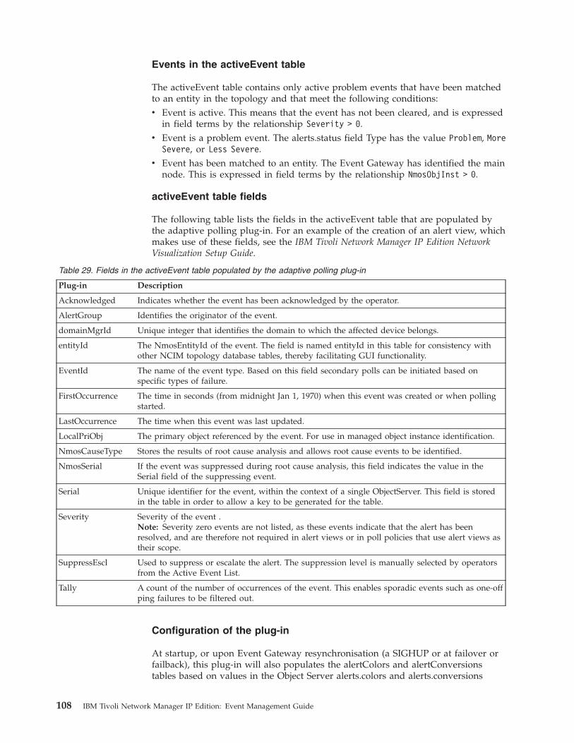
Events in the activeEvent table
The activeEvent table contains only active problem events that have been matchedto an entity in the topology and that meet the following conditions:v Event is active. This means that the event has not been cleared, and is expressed
in field terms by the relationship Severity > 0.v Event is a problem event. The alerts.status field Type has the value Problem, More
Severe, or Less Severe.v Event has been matched to an entity. The Event Gateway has identified the main
node. This is expressed in field terms by the relationship NmosObjInst > 0.
activeEvent table fields
The following table lists the fields in the activeEvent table that are populated bythe adaptive polling plug-in. For an example of the creation of an alert view, whichmakes use of these fields, see the IBM Tivoli Network Manager IP Edition NetworkVisualization Setup Guide.
Table 29. Fields in the activeEvent table populated by the adaptive polling plug-in
Plug-in Description
Acknowledged Indicates whether the event has been acknowledged by the operator.
AlertGroup Identifies the originator of the event.
domainMgrId Unique integer that identifies the domain to which the affected device belongs.
entityId The NmosEntityId of the event. The field is named entityId in this table for consistency withother NCIM topology database tables, thereby facilitating GUI functionality.
EventId The name of the event type. Based on this field secondary polls can be initiated based onspecific types of failure.
FirstOccurrence The time in seconds (from midnight Jan 1, 1970) when this event was created or when pollingstarted.
LastOccurrence The time when this event was last updated.
LocalPriObj The primary object referenced by the event. For use in managed object instance identification.
NmosCauseType Stores the results of root cause analysis and allows root cause events to be identified.
NmosSerial If the event was suppressed during root cause analysis, this field indicates the value in theSerial field of the suppressing event.
Serial Unique identifier for the event, within the context of a single ObjectServer. This field is storedin the table in order to allow a key to be generated for the table.
Severity Severity of the event .Note: Severity zero events are not listed, as these events indicate that the alert has beenresolved, and are therefore not required in alert views or in poll policies that use alert views astheir scope.
SuppressEscl Used to suppress or escalate the alert. The suppression level is manually selected by operatorsfrom the Active Event List.
Tally A count of the number of occurrences of the event. This enables sporadic events such as one-offping failures to be filtered out.
Configuration of the plug-in
At startup, or upon Event Gateway resynchronisation (a SIGHUP or at failover orfailback), this plug-in will also populates the alertColors and alertConversionstables based on values in the Object Server alerts.colors and alerts.conversions
108 IBM Tivoli Network Manager IP Edition: Event Management Guide
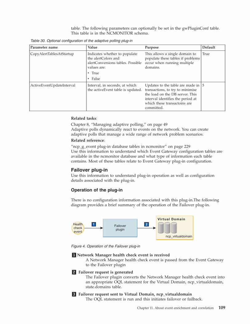
table. The following parameters can optionally be set in the gwPluginConf table.This table is in the NCMONITOR schema.
Table 30. Optional configuration of the adaptive polling plug-in
Parameter name Value Purpose Default
CopyAlertTablesAtStartup Indicates whether to populatethe alertColors andalertConversions tables. Possiblevalues are:
v True
v False
This allows a single domain topopulate these tables if problemsoccur when running multipledomains.
True
ActiveEventUpdateInterval Interval, in seconds, at whichthe activeEvent table is updated.
Updates to the table are made intransactions, to try to minimisethe load on the DB server. Thisinterval identifies the period atwhich these transactoins arecommitted.
5
Related tasks:Chapter 8, “Managing adaptive polling,” on page 49Adaptive polls dynamically react to events on the network. You can createadaptive polls that manage a wide range of network problem scenarios.Related reference:“ncp_g_event plug-in database tables in ncmonitor” on page 229Use this information to understand which Event Gateway configuration tables areavailable in the ncmonitor database and what type of information each tablecontains. Most of these tables relate to Event Gateway plug-in configuration.
Failover plug-inUse this information to understand plug-in operation as well as configurationdetails associated with the plug-in.
Operation of the plug-in
There is no configuration information associated with this plug-in.The followingdiagram provides a brief summary of the operation of the Failover plug-in.
�1�Network Manager health check event is receivedA Network Manager health check event is passed from the Event Gatewayto the Failover plugin
�2� Failover request is generatedThe Failover plugin converts the Network Manager health check event intoan appropriate OQL statement for the Virtual Domain, ncp_virtualdomain,state.domains table.
�3� Failover request sent to Virtual Domain, ncp_virtualdomainThe OQL statement is run and this initiates failover or failback.
Healthcheckevent
Failoverplugin
ncp_virtualdomain
Virtual Domain
1 2
Figure 4. Operation of the Failover plug-in
Chapter 11. About event enrichment and correlation 109
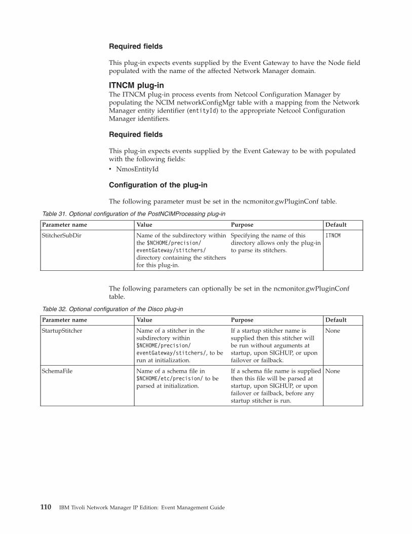
Required fields
This plug-in expects events supplied by the Event Gateway to have the Node fieldpopulated with the name of the affected Network Manager domain.
ITNCM plug-inThe ITNCM plug-in process events from Netcool Configuration Manager bypopulating the NCIM networkConfigMgr table with a mapping from the NetworkManager entity identifier (entityId) to the appropriate Netcool ConfigurationManager identifiers.
Required fields
This plug-in expects events supplied by the Event Gateway to be with populatedwith the following fields:v NmosEntityId
Configuration of the plug-in
The following parameter must be set in the ncmonitor.gwPluginConf table.
Table 31. Optional configuration of the PostNCIMProcessing plug-in
Parameter name Value Purpose Default
StitcherSubDir Name of the subdirectory withinthe $NCHOME/precision/eventGateway/stitchers/directory containing the stitchersfor this plug-in.
Specifying the name of thisdirectory allows only the plug-into parse its stitchers.
ITNCM
The following parameters can optionally be set in the ncmonitor.gwPluginConftable.
Table 32. Optional configuration of the Disco plug-in
Parameter name Value Purpose Default
StartupStitcher Name of a stitcher in thesubdirectory within$NCHOME/precision/eventGateway/stitchers/, to berun at initialization.
If a startup stitcher name issupplied then this stitcher willbe run without arguments atstartup, upon SIGHUP, or uponfailover or failback.
None
SchemaFile Name of a schema file in$NCHOME/etc/precision/ to beparsed at initialization.
If a schema file name is suppliedthen this file will be parsed atstartup, upon SIGHUP, or uponfailover or failback, before anystartup stitcher is run.
None
110 IBM Tivoli Network Manager IP Edition: Event Management Guide
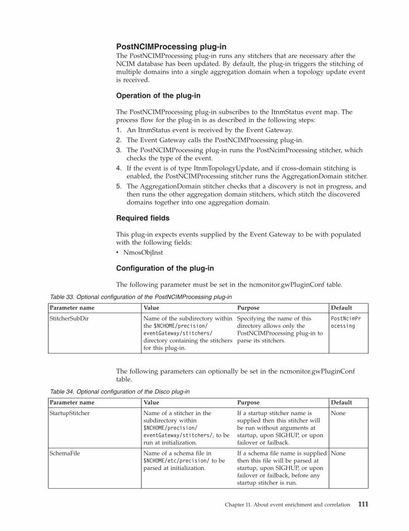
PostNCIMProcessing plug-inThe PostNCIMProcessing plug-in runs any stitchers that are necessary after theNCIM database has been updated. By default, the plug-in triggers the stitching ofmultiple domains into a single aggregation domain when a topology update eventis received.
Operation of the plug-in
The PostNCIMProcessing plug-in subscribes to the ItnmStatus event map. Theprocess flow for the plug-in is as described in the following steps:1. An ItnmStatus event is received by the Event Gateway.2. The Event Gateway calls the PostNCIMProcessing plug-in.3. The PostNCIMProcessing plug-in runs the PostNcimProcessing stitcher, which
checks the type of the event.4. If the event is of type ItnmTopologyUpdate, and if cross-domain stitching is
enabled, the PostNCIMProcessing stitcher runs the AggregationDomain stitcher.5. The AggregationDomain stitcher checks that a discovery is not in progress, and
then runs the other aggregation domain stitchers, which stitch the discovereddomains together into one aggregation domain.
Required fields
This plug-in expects events supplied by the Event Gateway to be with populatedwith the following fields:v NmosObjInst
Configuration of the plug-in
The following parameter must be set in the ncmonitor.gwPluginConf table.
Table 33. Optional configuration of the PostNCIMProcessing plug-in
Parameter name Value Purpose Default
StitcherSubDir Name of the subdirectory withinthe $NCHOME/precision/eventGateway/stitchers/directory containing the stitchersfor this plug-in.
Specifying the name of thisdirectory allows only thePostNCIMProcessing plug-in toparse its stitchers.
PostNcimProcessing
The following parameters can optionally be set in the ncmonitor.gwPluginConftable.
Table 34. Optional configuration of the Disco plug-in
Parameter name Value Purpose Default
StartupStitcher Name of a stitcher in thesubdirectory within$NCHOME/precision/eventGateway/stitchers/, to berun at initialization.
If a startup stitcher name issupplied then this stitcher willbe run without arguments atstartup, upon SIGHUP, or uponfailover or failback.
None
SchemaFile Name of a schema file in$NCHOME/etc/precision/ to beparsed at initialization.
If a schema file name is suppliedthen this file will be parsed atstartup, upon SIGHUP, or uponfailover or failback, before anystartup stitcher is run.
None
Chapter 11. About event enrichment and correlation 111
SAE plug-inThe SAE plug-in generates service-affected events for MPLS VPNs and IP paths.
By default the SAE plug-in enables the system to generate service-affected eventsfor the following services:v MPLS VPNsv IP pathsv Custom services
Each of these types of service-affected events is described in the following section:
MPLS VPN service-affected eventsA synthetic event generated when a Severity 5 (critical) fault event occurson a provider edge (PE) or customer edge (CE) router or on any of the PEinterfaces pointing towards a CE router in any of the discovered MPLSVPNs. The SAE generated is associated with the entity ID of the logicalentity in the discovery that represents the collection of MPLS VPN deviceson which the fault events occurred.
All PE to CE interfaces are added to a members list and an event on any ofthe interfaces in this members list causes the system to generate a syntheticMPLS VPN SAE.
You can enable the generation of SAE events based on interfacesdependencies deeper in the core network, by enabling theBGPPeerNextHopInterface discovery agent as part of your networkdiscovery. This agent calls the AddLayer3VPNInterfaceDependency.stchstitcher.This stitcher determines all PE to core provider router (P) interfaces and Pto PE interfaces involved in a VPN. These PE -> P and P ->PE interfacesare added to a dependency list. An event on any of the interfaces in thisdependency list causes the system to generate a synthetic MPLS VPN SAE.If an MPLS VPN SAE has already been generated based on an event onany of the interfaces in the members list, then any events in interfaces inthe dependency list will be added as related events to that alreadygenerated MPLS VPN SAE.
For more information on the BGPPeerNextHopInterface discovery agentand the AddLayer3VPNInterfaceDependency.stch stitcher, see the IBMTivoli Network Manager IP Edition Discovery Guide
IP path service-affected eventsA synthetic event generated when an event occurs on a device within anyof the IP paths created using the Network Paths GUI. The SAE generatedis associated with the entity ID that corresponds to the IP path containingthe device on which the event occurred.
Customizable service-affected eventsThe SAE plug-in can be configured to generated synthetic events when aan event occurs on a device associated with a custom service. In order toperform this configuration you must perform the following tasks:1. Configure the Discovery engine, ncp_disco, to collect data for the
custom service. Perform this configuration by writing a custom stitcherto define the custom service and ensure that this stitcher is called bythe relevant standard Network Manager stitcher.
Note: For help with writing custom stitchers, contact IBM Support.
112 IBM Tivoli Network Manager IP Edition: Event Management Guide
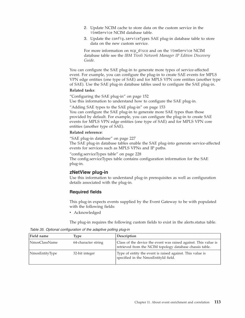
2. Update NCIM cache to store data on the custom service in theitnmService NCIM database table.
3. Update the config.serviceTypes SAE plug-in database table to storedata on the new custom service.
For more information on ncp_disco and on the itnmService NCIMdatabase table see the IBM Tivoli Network Manager IP Edition DiscoveryGuide.
You can configure the SAE plug-in to generate more types of service-affectedevent. For example, you can configure the plug-in to create SAE events for MPLSVPN edge entities (one type of SAE) and for MPLS VPN core entities (another typeof SAE). Use the SAE plug-in database tables used to configure the SAE plug-in.Related tasks:“Configuring the SAE plug-in” on page 152Use this information to understand how to configure the SAE plug-in.“Adding SAE types to the SAE plug-in” on page 153You can configure the SAE plug-in to generate more SAE types than thoseprovided by default. For example, you can configure the plug-in to create SAEevents for MPLS VPN edge entities (one type of SAE) and for MPLS VPN coreentities (another type of SAE).Related reference:“SAE plug-in database” on page 227The SAE plug-in database tables enable the SAE plug-into generate service-affectedevents for services such as MPLS VPNs and IP paths.“config.serviceTypes table” on page 228The config.serviceTypes table contains configuration information for the SAEplug-in.
zNetView plug-inUse this information to understand plug-in prerequisites as well as configurationdetails associated with the plug-in.
Required fields
This plug-in expects events supplied by the Event Gateway to be with populatedwith the following fields:v Acknowledged
The plug-in requires the following custom fields to exist in the alerts.status table.
Table 35. Optional configuration of the adaptive polling plug-in
Field name Type Description
NmosClassName 64-character string Class of the device the event was raised against. This value isretrieved from the NCIM topology database chassis table.
NmosEntityType 32-bit integer Type of entity the event is raised against. This value isspecified in the NmosEntityId field.
Chapter 11. About event enrichment and correlation 113
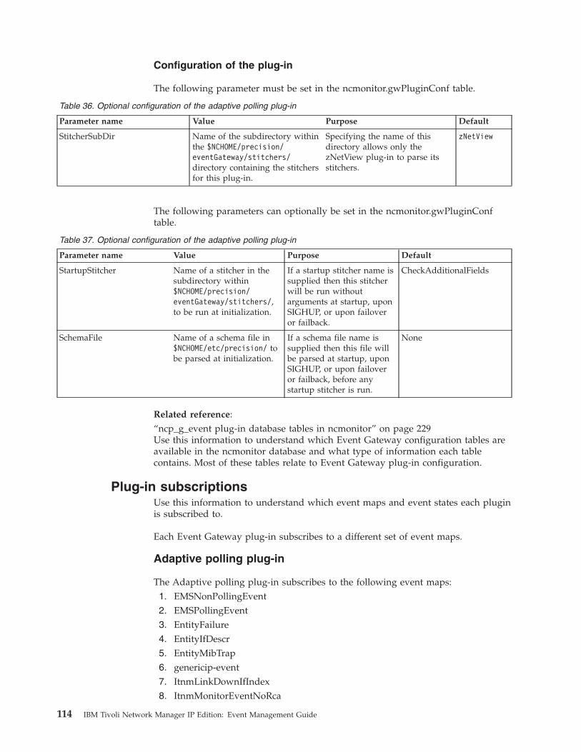
Configuration of the plug-in
The following parameter must be set in the ncmonitor.gwPluginConf table.
Table 36. Optional configuration of the adaptive polling plug-in
Parameter name Value Purpose Default
StitcherSubDir Name of the subdirectory withinthe $NCHOME/precision/eventGateway/stitchers/directory containing the stitchersfor this plug-in.
Specifying the name of thisdirectory allows only thezNetView plug-in to parse itsstitchers.
zNetView
The following parameters can optionally be set in the ncmonitor.gwPluginConftable.
Table 37. Optional configuration of the adaptive polling plug-in
Parameter name Value Purpose Default
StartupStitcher Name of a stitcher in thesubdirectory within$NCHOME/precision/eventGateway/stitchers/,to be run at initialization.
If a startup stitcher name issupplied then this stitcherwill be run withoutarguments at startup, uponSIGHUP, or upon failoveror failback.
CheckAdditionalFields
SchemaFile Name of a schema file in$NCHOME/etc/precision/ tobe parsed at initialization.
If a schema file name issupplied then this file willbe parsed at startup, uponSIGHUP, or upon failoveror failback, before anystartup stitcher is run.
None
Related reference:“ncp_g_event plug-in database tables in ncmonitor” on page 229Use this information to understand which Event Gateway configuration tables areavailable in the ncmonitor database and what type of information each tablecontains. Most of these tables relate to Event Gateway plug-in configuration.
Plug-in subscriptionsUse this information to understand which event maps and event states each pluginis subscribed to.
Each Event Gateway plug-in subscribes to a different set of event maps.
Adaptive polling plug-in
The Adaptive polling plug-in subscribes to the following event maps:1. EMSNonPollingEvent2. EMSPollingEvent3. EntityFailure4. EntityIfDescr5. EntityMibTrap6. genericip-event7. ItnmLinkDownIfIndex8. ItnmMonitorEventNoRca
114 IBM Tivoli Network Manager IP Edition: Event Management Guide
9. LinkDownIfDescr10. LinkDownIfIndex11. LinkDownIfName12. NbrFail13. NbrFailIfDescr14. OSPFIfState15. OSPFIfStateChange16. OSPFIfStateChangeIP17. PollFailure18. PrecisionMonitorEvent19. Reconfiguration
The Adaptive polling plug-in subscribes to the following event states:1. Cleared2. Deleted3. Occurred4. ReAwakened5. ReOccurred6. ReSync7. Updated
Disco plug-in
The Disco plug-in subscribes to the Reconfiguration event map.
Failover plug-in
This plug-in subscribes to the ItnmHealthChk event map.
The Failover plug-in subscribes to the following event states:1. Cleared2. Occurred3. ReAwakened4. ReCleared5. ReOccurred6. Resolution7. ReSync
ITNM plug-in
This plug-in subscribes to the ItncmResourceEvent event map.
The Failover plug-in subscribes to the following event states:1. Information2. Occurred
Chapter 11. About event enrichment and correlation 115
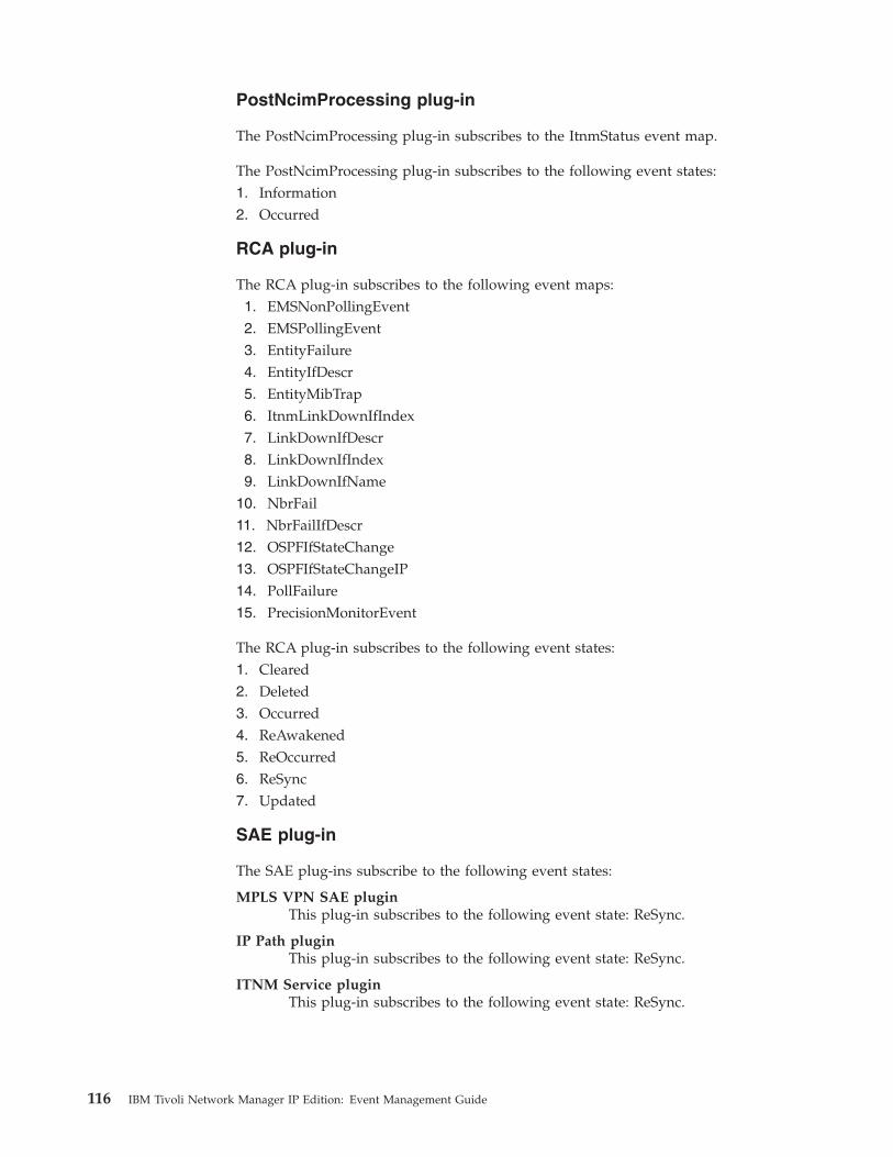
PostNcimProcessing plug-in
The PostNcimProcessing plug-in subscribes to the ItnmStatus event map.
The PostNcimProcessing plug-in subscribes to the following event states:1. Information2. Occurred
RCA plug-in
The RCA plug-in subscribes to the following event maps:1. EMSNonPollingEvent2. EMSPollingEvent3. EntityFailure4. EntityIfDescr5. EntityMibTrap6. ItnmLinkDownIfIndex7. LinkDownIfDescr8. LinkDownIfIndex9. LinkDownIfName
10. NbrFail11. NbrFailIfDescr12. OSPFIfStateChange13. OSPFIfStateChangeIP14. PollFailure15. PrecisionMonitorEvent
The RCA plug-in subscribes to the following event states:1. Cleared2. Deleted3. Occurred4. ReAwakened5. ReOccurred6. ReSync7. Updated
SAE plug-in
The SAE plug-ins subscribe to the following event states:
MPLS VPN SAE pluginThis plug-in subscribes to the following event state: ReSync.
IP Path pluginThis plug-in subscribes to the following event state: ReSync.
ITNM Service pluginThis plug-in subscribes to the following event state: ReSync.
116 IBM Tivoli Network Manager IP Edition: Event Management Guide
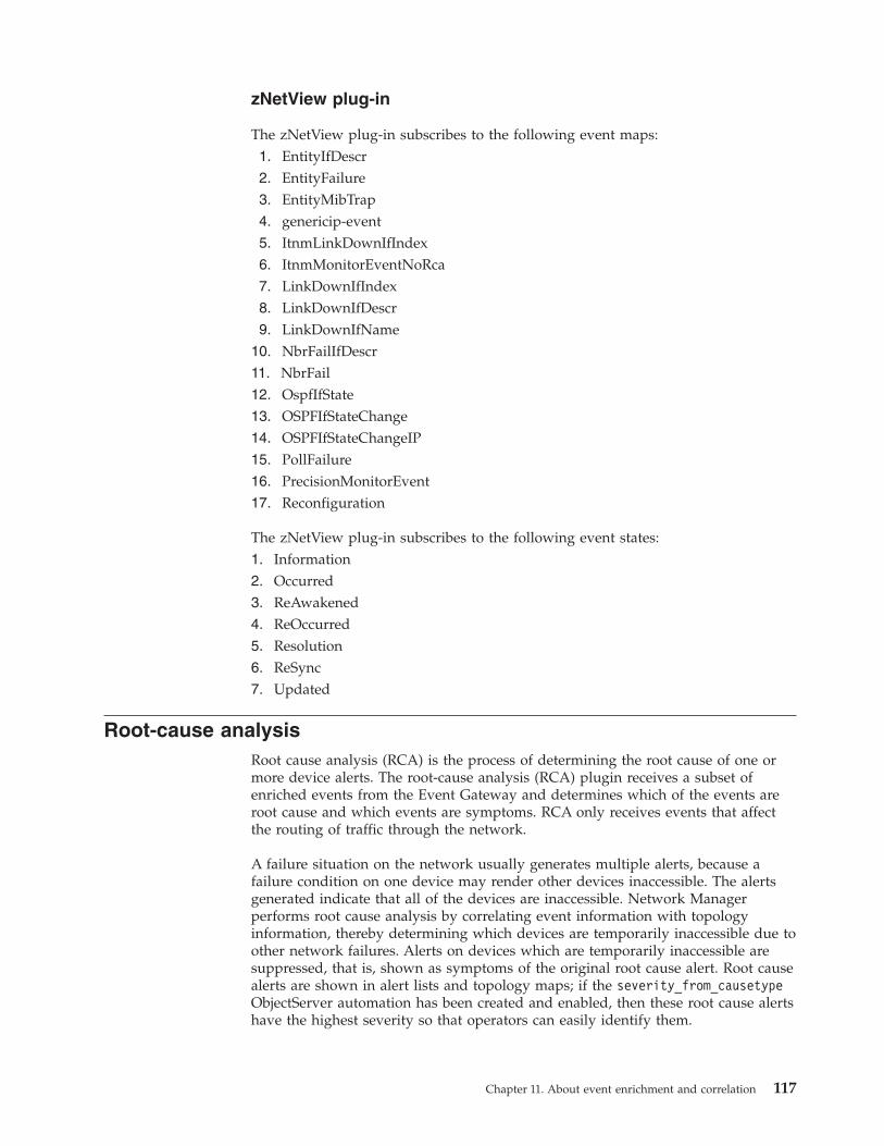
zNetView plug-in
The zNetView plug-in subscribes to the following event maps:1. EntityIfDescr2. EntityFailure3. EntityMibTrap4. genericip-event5. ItnmLinkDownIfIndex6. ItnmMonitorEventNoRca7. LinkDownIfIndex8. LinkDownIfDescr9. LinkDownIfName
10. NbrFailIfDescr11. NbrFail12. OspfIfState13. OSPFIfStateChange14. OSPFIfStateChangeIP15. PollFailure16. PrecisionMonitorEvent17. Reconfiguration
The zNetView plug-in subscribes to the following event states:1. Information2. Occurred3. ReAwakened4. ReOccurred5. Resolution6. ReSync7. Updated
Root-cause analysisRoot cause analysis (RCA) is the process of determining the root cause of one ormore device alerts. The root-cause analysis (RCA) plugin receives a subset ofenriched events from the Event Gateway and determines which of the events areroot cause and which events are symptoms. RCA only receives events that affectthe routing of traffic through the network.
A failure situation on the network usually generates multiple alerts, because afailure condition on one device may render other devices inaccessible. The alertsgenerated indicate that all of the devices are inaccessible. Network Managerperforms root cause analysis by correlating event information with topologyinformation, thereby determining which devices are temporarily inaccessible due toother network failures. Alerts on devices which are temporarily inaccessible aresuppressed, that is, shown as symptoms of the original root cause alert. Root causealerts are shown in alert lists and topology maps; if the severity_from_causetypeObjectServer automation has been created and enabled, then these root cause alertshave the highest severity so that operators can easily identify them.
Chapter 11. About event enrichment and correlation 117
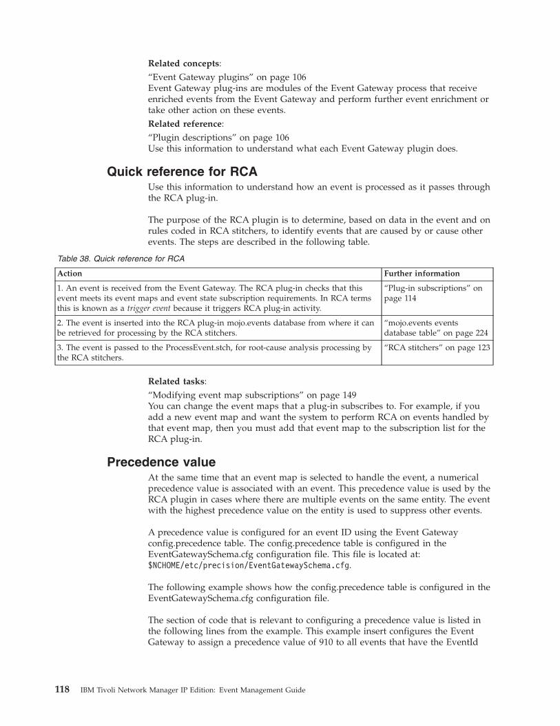
Related concepts:“Event Gateway plugins” on page 106Event Gateway plug-ins are modules of the Event Gateway process that receiveenriched events from the Event Gateway and perform further event enrichment ortake other action on these events.Related reference:“Plugin descriptions” on page 106Use this information to understand what each Event Gateway plugin does.
Quick reference for RCAUse this information to understand how an event is processed as it passes throughthe RCA plug-in.
The purpose of the RCA plugin is to determine, based on data in the event and onrules coded in RCA stitchers, to identify events that are caused by or cause otherevents. The steps are described in the following table.
Table 38. Quick reference for RCA
Action Further information
1. An event is received from the Event Gateway. The RCA plug-in checks that thisevent meets its event maps and event state subscription requirements. In RCA termsthis is known as a trigger event because it triggers RCA plug-in activity.
“Plug-in subscriptions” onpage 114
2. The event is inserted into the RCA plug-in mojo.events database from where it canbe retrieved for processing by the RCA stitchers.
“mojo.events eventsdatabase table” on page 224
3. The event is passed to the ProcessEvent.stch, for root-cause analysis processing bythe RCA stitchers.
“RCA stitchers” on page 123
Related tasks:“Modifying event map subscriptions” on page 149You can change the event maps that a plug-in subscribes to. For example, if youadd a new event map and want the system to perform RCA on events handled bythat event map, then you must add that event map to the subscription list for theRCA plug-in.
Precedence valueAt the same time that an event map is selected to handle the event, a numericalprecedence value is associated with an event. This precedence value is used by theRCA plugin in cases where there are multiple events on the same entity. The eventwith the highest precedence value on the entity is used to suppress other events.
A precedence value is configured for an event ID using the Event Gatewayconfig.precedence table. The config.precedence table is configured in theEventGatewaySchema.cfg configuration file. This file is located at:$NCHOME/etc/precision/EventGatewaySchema.cfg.
The following example shows how the config.precedence table is configured in theEventGatewaySchema.cfg configuration file.
The section of code that is relevant to configuring a precedence value is listed inthe following lines from the example. This example insert configures the EventGateway to assign a precedence value of 910 to all events that have the EventId
118 IBM Tivoli Network Manager IP Edition: Event Management Guide
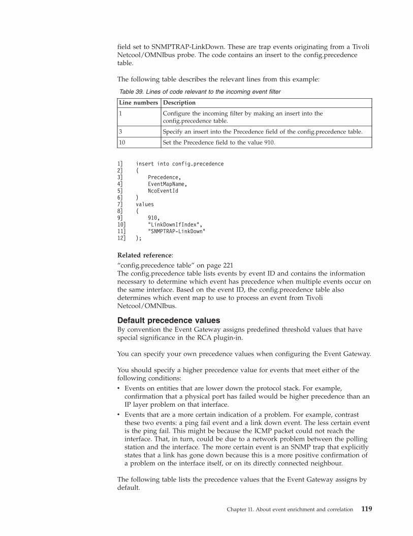
field set to SNMPTRAP-LinkDown. These are trap events originating from a TivoliNetcool/OMNIbus probe. The code contains an insert to the config.precedencetable.
The following table describes the relevant lines from this example:
Table 39. Lines of code relevant to the incoming event filter
Line numbers Description
1 Configure the incoming filter by making an insert into theconfig.precedence table.
3 Specify an insert into the Precedence field of the config.precedence table.
10 Set the Precedence field to the value 910.
1]2]3]4]5]6]7]8]9]10]11]12]
insert into config.precedence(
Precedence,EventMapName,NcoEventId
)values(
910,"LinkDownIfIndex","SNMPTRAP-LinkDown"
);
Related reference:“config.precedence table” on page 221The config.precedence table lists events by event ID and contains the informationnecessary to determine which event has precedence when multiple events occur onthe same interface. Based on the event ID, the config.precedence table alsodetermines which event map to use to process an event from TivoliNetcool/OMNIbus.
Default precedence valuesBy convention the Event Gateway assigns predefined threshold values that havespecial significance in the RCA plugin-in.
You can specify your own precedence values when configuring the Event Gateway.
You should specify a higher precedence value for events that meet either of thefollowing conditions:v Events on entities that are lower down the protocol stack. For example,
confirmation that a physical port has failed would be higher precedence than anIP layer problem on that interface.
v Events that are a more certain indication of a problem. For example, contrastthese two events: a ping fail event and a link down event. The less certain eventis the ping fail. This might be because the ICMP packet could not reach theinterface. That, in turn, could be due to a network problem between the pollingstation and the interface. The more certain event is an SNMP trap that explicitlystates that a link has gone down because this is a more positive confirmation ofa problem on the interface itself, or on its directly connected neighbour.
The following table lists the precedence values that the Event Gateway assigns bydefault.
Chapter 11. About event enrichment and correlation 119
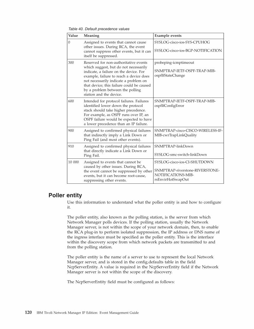
Table 40. Default precedence values
Value Meaning Example events
0 Assigned to events that cannot causeother issues. During RCA, the eventcannot suppress other events, but it canitself be suppressed.
SYSLOG-cisco-ios-SYS-CPUHOG
SYSLOG-cisco-ios-BGP-NOTIFICATION
300 Reserved for non-authoritative eventswhich suggest, but do not necessarilyindicate, a failure on the device. Forexample, failure to reach a device doesnot necessarily indicate a problem onthat device; this failure could be causedby a problem between the pollingstation and the device.
probeping-icmptimeout
SNMPTRAP-IETF-OSPF-TRAP-MIB-ospfIfStateChange
600 Intended for protocol failures. Failuresidentified lower down the protocolstack should take higher precedence.For example, as OSPF runs over IP, anOSPF failure would be expected to havea lower precedence than an IP failure.
SNMPTRAP-IETF-OSPF-TRAP-MIB-ospfIfConfigError
900 Assigned to confirmed physical failuresthat indirectly imply a Link Down orPing Fail (and most other events).
SNMPTRAP-cisco-CISCO-WIRELESS-IF-MIB-cwrTrapLinkQuality
910 Assigned to confirmed physical failuresthat directly indicate a Link Down orPing Fail.
SNMPTRAP-linkDown
SYSLOG-smc-switch-linkDown
10 000 Assigned to events that cannot becaused by other issues. During RCA,the event cannot be suppressed by otherevents, but it can become root-cause,suppressing other events.
SYSLOG-cisco-ios-CI-SHUTDOWN
SNMPTRAP-riverstone-RIVERSTONE-NOTIFICATIONS-MIB-rsEnvirHotSwapOut
Poller entityUse this information to understand what the poller entity is and how to configureit.
The poller entity, also known as the polling station, is the server from whichNetwork Manager polls devices. If the polling station, usually the NetworkManager server, is not within the scope of your network domain, then, to enablethe RCA plug-in to perform isolated suppression, the IP address or DNS name ofthe ingress interface must be specified as the poller entity. This is the interfacewithin the discovery scope from which network packets are transmitted to andfrom the polling station.
The poller entity is the name of a server to use to represent the local NetworkManager server, and is stored in the config.defaults table in the fieldNcpServerEntity. A value is required in the NcpServerEntity field if the NetworkManager server is not within the scope of the discovery.
The NcpServerEntity field must be configured as follows:
120 IBM Tivoli Network Manager IP Edition: Event Management Guide

Table 41. NcpServerEntity field configuration settings
Is Network Manager server in discoveryscope? Value of NcpServerEntity field
Yes Empty string
No IP address or DNS name of the ingressinterface
The following diagram shows the ingress interface (circled) when the NetworkManager server is outside discovery scope.
Note: You must have run at least one discovery in order for the Event Gateway tofind the poller entity in the NCIM database.
Related tasks:“Configuring the poller entity” on page 155When the Network Manager server is not within the scope of your networkdomain, or you have several domains, specify the IP address or DNS name of thepoller entity.
Router XNetwork Manager
server
Router Y
Discovery scopeof NetworkManager domain
Figure 5. Ingress interface
Chapter 11. About event enrichment and correlation 121
RCA and unmanaged statusUse this information to understand how the RCA plug-in handles events fromdevices that are in unmanaged state, also known as maintenance state.
The method used by the RCA plug-in to handle events from devices that are inunmanaged state is governed by the value set for the HonourManagedStatus in theRCA plug-in configuration file $NCHOME/etc/precision/RCASchema.cfg. This fieldcan take the following values.v 1 (default value): instructs the RCA plug-in to honour the managed status of
events. All events from unmanaged devices are ignored.v 0: instructs the RCA plug-in to process events from unmanaged devices as
normal events.
In each case, the RCA plug-in determines whether the device is unmanaged bylooking at the NmosManagedStatus field of the event.
Assuming that the RCA plug-in is configured to honour the managed status ofevents (HonourManagedStatus = 1), then an event from an unmanaged devicecannot be root cause and it cannot be suppressed.
If the event has an event state of ReOccurred and earlier occurrences of this sameevent indicated that the device was previously managed, then the event record inthe mojo.events database is updated and will have its NmosCauseType, NmosSerialand SuppressionState reset to 0, in effect instructing the RCA plug-in to nowignore this event. The managed status of reoccurring events can change because ofthe following: managed Status is a property of an entity; for example, an interface.The managed status of the entity is stored in a field in the entity record. Inaddition, events raised on an entity also contain a field called NmosManagedStatusthat records the managed status of the entity at the time the event was raised.Therefore it is possible for an event to occur when an entity is being managed, butthen later on the same event could reoccur when the entity is unmanaged, that is,after the entity has changed state from managed to unmanaged.
The following scenarios explain how the RCA plug-in handles events whosemanaged status changes on subsequent occurrences.
Event changes from managed to unmanaged
The sequence is as follows:1. The initially occurring event (for example, a ping fail event) is processed as
normal for RCA, since the event had an NmosManagedStatus of 0, meaning thatthe entity was managed when the event first occurred.
2. Then, some time later, the interface entity is set to unmanaged; that is, theManagedStatus value for the interface becomes 1.
3. The event on the interface reoccurs.4. The reoccurred ping fail event now contains the field value NmosManagedStatus
= 1, but the previous occurrence of this event, still in the database mojo.events,had the field value NmosManagedStatus = 0.
5. The RCA plug-in detects that the the value of the field NmosManagedStatus haschanged from 0 to 1, for the ReOccurred (or Updated) event.
122 IBM Tivoli Network Manager IP Edition: Event Management Guide
6. The RCA plug-in updates the event record in the database mojo.events andfrom then on treats the event is as it would treat a deleted event; that is, itreprocesses all the suppressees of the event as because this event no longerallowed to suppress events.
Event changes from unmanaged to managed
The sequence is as follows:1. The initially occurring event (for example, a ping fail event) arrives with a
NmosManagedStatus of 1 meaning that the entity was unmanaged when theevent first occurred.Therefore the event is processed as if it were a deletedevent and is not allowed to suppress events.
2. Then, some time later, the interface entity is set to managed; that is, theManagedStatus value for the interface becomes 0.
3. The event on the interface reoccurs.4. The reoccurred ping fail event now contains the field value NmosManagedStatus
= 0, but the previous occurrence of this event, still in the database mojo.events,had the field value NmosManagedStatus = 1.
5. The RCA plug-in detects that the the value of the field NmosManagedStatus haschanged from 1 to 0, for the ReOccurred (or Updated) event.
6. The RCA plug-in updates the event record in the database mojo.events andfrom then on treats the event is as a normal event; this event now allowed tosuppress other events.
Related reference:“config.defaults database table” on page 226The config.defaults database table stores configuration data for the RCA plug-inevent queue.
RCA stitchersRCA stitchers process a trigger event as it passes through the RCA plug-in.
RCA plug-in stitchers are stored in the following location: $NCHOME/precision/eventGateway/stitchers/RCA.
For information on stitcher language, see the IBM Tivoli Network Manager IP EditionLanguage Reference.
RCA stitcher sequenceUse this information to understand which stitcher is called first by the RCAplug-in and the sequence in which stitchers are then run.
The following diagram shows the sequence in which the RCA stitchers are run.
Chapter 11. About event enrichment and correlation 123
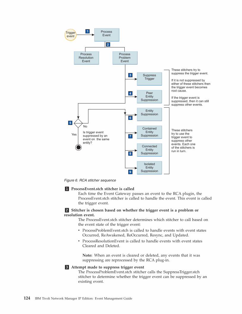
�1� ProcessEvent.stch stitcher is calledEach time the Event Gateway passes an event to the RCA plugin, theProcessEvent.stch stitcher is called to handle the event. This event is calledthe trigger event.
�2� Stitcher is chosen based on whether the trigger event is a problem orresolution event.
The ProcessEvent.stch stitcher determines which stitcher to call based onthe event state of the trigger event:v ProcessProblemEvent.stch is called to handle events with event states
Occurred, ReAwakened, ReOccurred, Resync, and Updated.v ProcessResolutionEvent is called to handle events with event states
Cleared and Deleted.
Note: When an event is cleared or deleted, any events that it wassuppressing are reprocessed by the RCA plug-in.
�3� Attempt made to suppress trigger eventThe ProcessProblemEvent.stch stitcher calls the SuppressTrigger.stchstitcher to determine whether the trigger event can be suppressed by anexisting event.
Triggerevent
ProcessEvent
1
EntitySuppression
ContainedEntity
Suppression
ConnectedEntity
Suppression
IsolatedEntity
Suppression
SuppressTrigger
PeerEntity
Suppression
ProcessResolution
Event
ProcessProblem
Event
These stitchers try tosuppress the trigger event.
If it is not suppressed byeither of these stitchers thenthe trigger event becomesroot cause.
If the trigger event issuppressed, then it can stillsuppress other events.
These stitcherstry to use thetrigger event tosuppress otherevents. Each oneof the stitchers isrun in turn.
2
3
4
6
7
8
9
5No
YesIs trigger eventsuppressed by anevent on the sameentity?
Figure 6. RCA stitcher sequence
124 IBM Tivoli Network Manager IP Edition: Event Management Guide

�4� Attempt made to suppress OSPF or BGP trigger eventIf the event is an OSPF or BGP event, then the ProcessProblemEvent.stchstitcher calls the PeerEntitySuppression.stch stitcher to determine whetherthe trigger event can be suppressed by another event on the peer entity.
�5� Check to see whether trigger event is entity suppressed, that is, it is not themaster event for this entity
Is this trigger event suppressed by another event on the same entity? If sodo not let it suppress anything as the suppression will have been done bythe master event on this entity.
�6� Attempt made to use trigger event to suppress other events based on sameentity suppression
The ProcessProblemEvent.stch stitcher calls the EntitySuppression.stchstitcher. This stitcher uses the trigger event to attempt to suppress otherevents using same entity suppression principles. The event with thehighest precedence on the same entity suppresses the other events on thatentity.
�7� Attempt made to use trigger event to suppress other events based oncontained entity principles
The ProcessProblemEvent.stch stitcher calls theContainedEntitySuppression.stch stitcher. This stitcher uses the triggerevent to attempt to suppress other events using contained entity principles.The event on the containing entity suppresses events on all containedentities.
�8� Attempt made to use trigger event to suppress other events based onconnected entity principles
The ProcessProblemEvent.stch stitcher calls theConnectedEntitySuppression.stch stitcher. This stitcher uses the triggerevent to attempt to suppress other events using connected entityprinciples. For example, when two interfaces are connected and there is anevent on both, the event on one of the interfaces suppresses the event onthe other interface.
�9� Attempt made to use trigger event to suppress other events based ondownstream entity principles
The ProcessProblemEvent.stch stitcher calls theIsolatedEntitySuppression.stch stitcher. This stitcher uses the trigger eventto attempt to suppress other events using downstream entity principles.
Related concepts:“Event states” on page 80The Event Gateway assigns a state to the event based on the type of event, andbased on the Severity and Tally fields in the event. The event state is one of theparameters used by event plug-ins when subscribing to events.
Chapter 11. About event enrichment and correlation 125
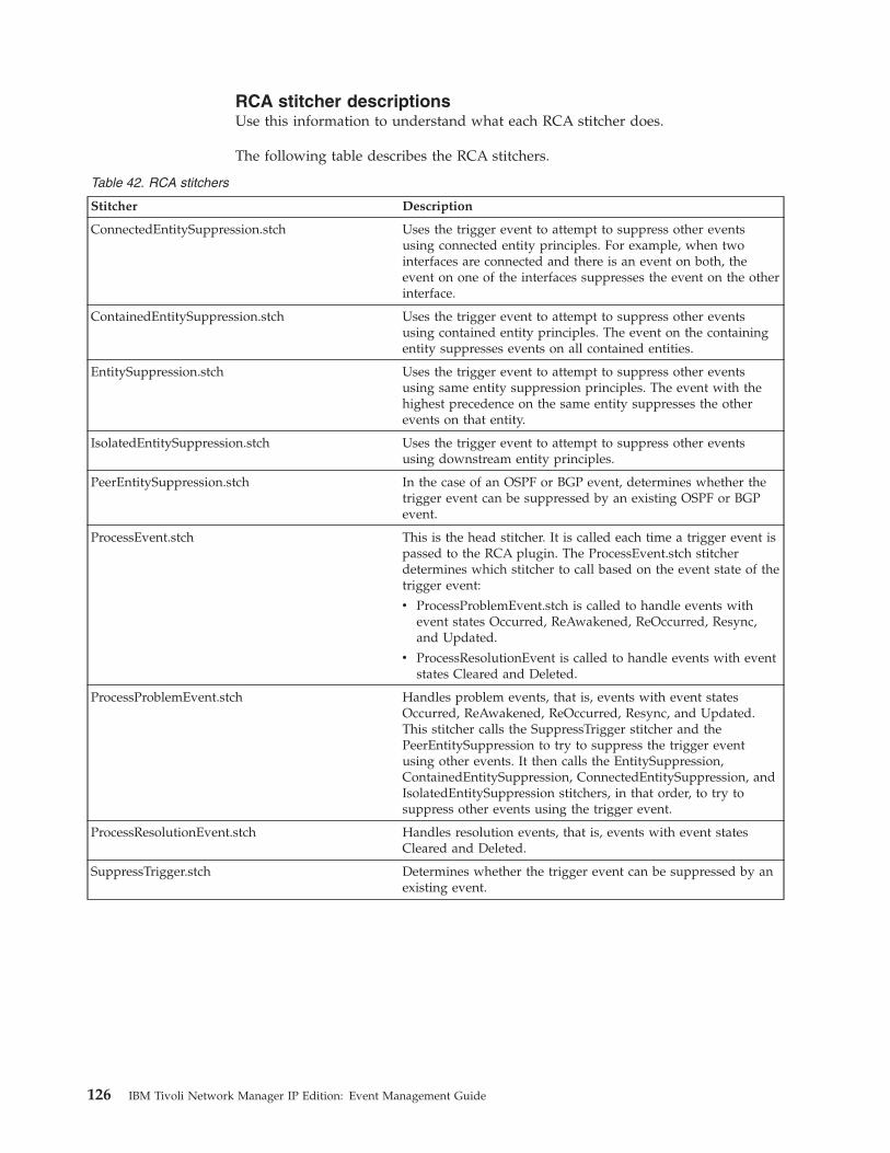
RCA stitcher descriptionsUse this information to understand what each RCA stitcher does.
The following table describes the RCA stitchers.
Table 42. RCA stitchers
Stitcher Description
ConnectedEntitySuppression.stch Uses the trigger event to attempt to suppress other eventsusing connected entity principles. For example, when twointerfaces are connected and there is an event on both, theevent on one of the interfaces suppresses the event on the otherinterface.
ContainedEntitySuppression.stch Uses the trigger event to attempt to suppress other eventsusing contained entity principles. The event on the containingentity suppresses events on all contained entities.
EntitySuppression.stch Uses the trigger event to attempt to suppress other eventsusing same entity suppression principles. The event with thehighest precedence on the same entity suppresses the otherevents on that entity.
IsolatedEntitySuppression.stch Uses the trigger event to attempt to suppress other eventsusing downstream entity principles.
PeerEntitySuppression.stch In the case of an OSPF or BGP event, determines whether thetrigger event can be suppressed by an existing OSPF or BGPevent.
ProcessEvent.stch This is the head stitcher. It is called each time a trigger event ispassed to the RCA plugin. The ProcessEvent.stch stitcherdetermines which stitcher to call based on the event state of thetrigger event:
v ProcessProblemEvent.stch is called to handle events withevent states Occurred, ReAwakened, ReOccurred, Resync,and Updated.
v ProcessResolutionEvent is called to handle events with eventstates Cleared and Deleted.
ProcessProblemEvent.stch Handles problem events, that is, events with event statesOccurred, ReAwakened, ReOccurred, Resync, and Updated.This stitcher calls the SuppressTrigger stitcher and thePeerEntitySuppression to try to suppress the trigger eventusing other events. It then calls the EntitySuppression,ContainedEntitySuppression, ConnectedEntitySuppression, andIsolatedEntitySuppression stitchers, in that order, to try tosuppress other events using the trigger event.
ProcessResolutionEvent.stch Handles resolution events, that is, events with event statesCleared and Deleted.
SuppressTrigger.stch Determines whether the trigger event can be suppressed by anexisting event.
126 IBM Tivoli Network Manager IP Edition: Event Management Guide
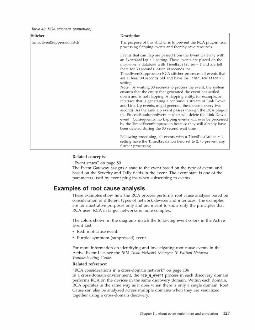
Table 42. RCA stitchers (continued)
Stitcher Description
TimedEventSuppression.stch The purpose of this stitcher is to prevent the RCA plug-in fromprocessing flapping events and thereby save resources.
Events that can flap are passed from the Event Gateway withan EventCanFlap = 1 setting. These events are placed on themojo.events database with TimedEscalation = 1 and are leftthere for 30 seconds. After 30 seconds theTimedEventSuppression RCA stitcher processes all events thatare at least 30 seconds old and have the TimedEscalation = 1setting.Note: By waiting 30 seconds to process the event, the systemensures that the entity that generated the event has settleddown and is not flapping. A flapping entity, for example, aninterface that is generating a continuous stream of Link Downand Link Up events, might generate these events every twoseconds. As the Link Up event passes through the RCA plug-in,the ProcessResolutionEvent stitcher will delete the Link Downevent . Consequently, no flapping events will ever be processedby the TimedEventSuppression because they will already havebeen deleted during the 30 second wait time.
Following processing, all events with a TimedEscalation = 1setting have the TimedEscalation field set to 2, to prevent anyfurther processing.
Related concepts:“Event states” on page 80The Event Gateway assigns a state to the event based on the type of event, andbased on the Severity and Tally fields in the event. The event state is one of theparameters used by event plug-ins when subscribing to events.
Examples of root cause analysisThese examples show how the RCA process performs root cause analysis based onconsideration of different types of network devices and interfaces. The examplesare for illustrative purposes only and are meant to show only the principles thatRCA uses. RCA in larger networks is more complex.
The colors shown in the diagrams match the following event colors in the ActiveEvent List:v Red: root-cause event.v Purple: symptom (suppressed) event.
For more information on identifying and investigating root-cause events in theActive Event List, see the IBM Tivoli Network Manager IP Edition NetworkTroubleshooting Guide.Related reference:“RCA considerations in a cross-domain network” on page 136In a cross-domain environment, the ncp_g_event process in each discovery domainperforms RCA on the devices in the same discovery domain. Within each domain,RCA operates in the same way as it does when there is only a single domain. RootCause can also be analyzed across multiple domains when they are visualizedtogether using a cross-domain discovery.
Chapter 11. About event enrichment and correlation 127
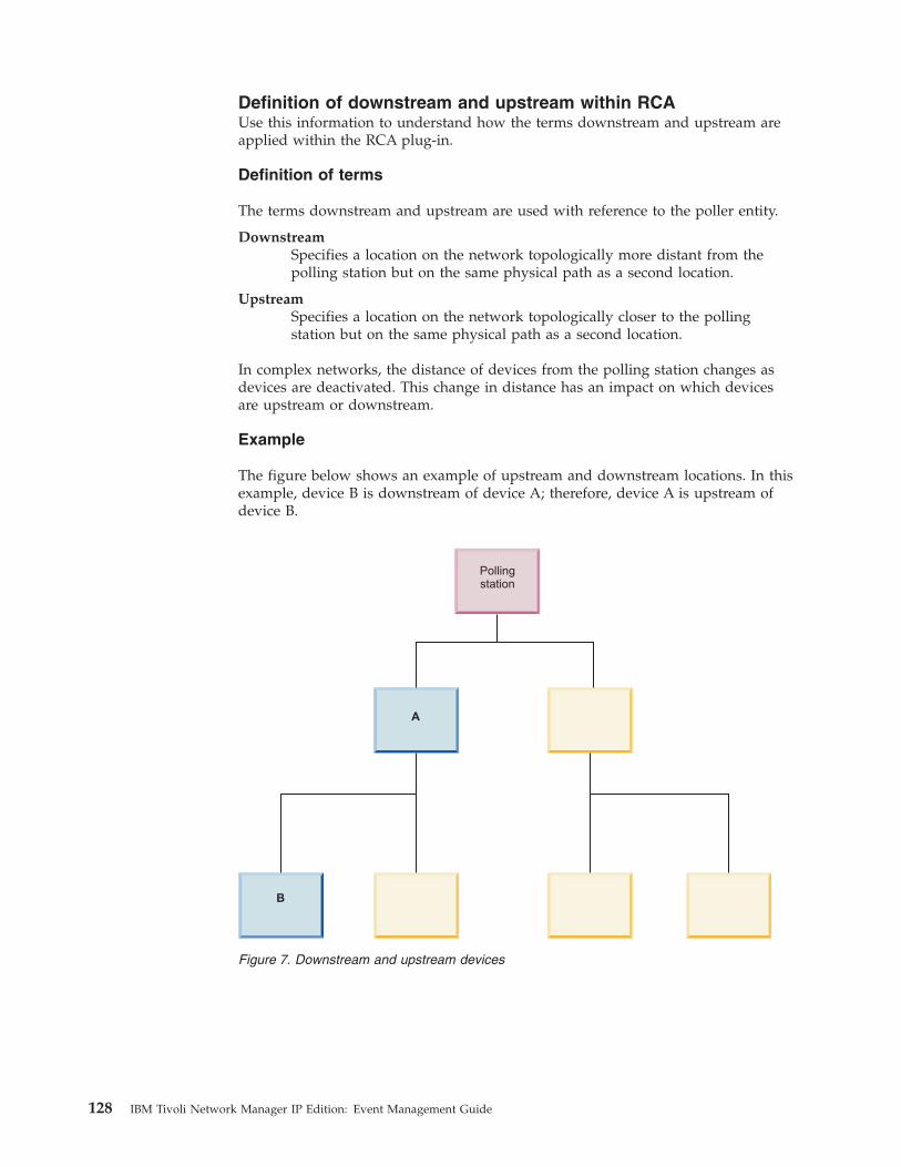
Definition of downstream and upstream within RCAUse this information to understand how the terms downstream and upstream areapplied within the RCA plug-in.
Definition of terms
The terms downstream and upstream are used with reference to the poller entity.
DownstreamSpecifies a location on the network topologically more distant from thepolling station but on the same physical path as a second location.
UpstreamSpecifies a location on the network topologically closer to the pollingstation but on the same physical path as a second location.
In complex networks, the distance of devices from the polling station changes asdevices are deactivated. This change in distance has an impact on which devicesare upstream or downstream.
Example
The figure below shows an example of upstream and downstream locations. In thisexample, device B is downstream of device A; therefore, device A is upstream ofdevice B.
A
B
Pollingstation
Figure 7. Downstream and upstream devices
128 IBM Tivoli Network Manager IP Edition: Event Management Guide
Related reference:“Isolated suppression of chassis devices” on page 132A failure on a chassis device suppresses failures on all chassis devices isolated bythe chassis device where the failure occurred. This is an example of isolatedsuppression.“Isolated suppression for devices at the edge of a network” on page 135A failure on a logical or physical interface that is the sole connection between otherentities and the network suppresses failures in the downstream entities. This is anexample of isolated suppression.
Chassis devices and loopback interfacesIn most cases, the RCA process assumes that if a chassis fails, then the root causefor other failures originates in the chassis. Chassis failures suppress failures oncontained interfaces, connected interfaces and downstream chassis devices.
The loopback interface has a special function within a chassis device, whetherrouter or switch. A loopback interface always has an IP address, whichcorresponds to the IP address of the chassis device.Network Manager associatesthe loopback interface with the chassis during discovery. The loopback interfacerepresents the whole chassis and can be polled individually. Failures on theloopback interface suppress failures on connected and contained entities in exactlythe same way as failures on chassis devices.
Only events on chassis devices, interfaces, modules, and cards are allowed toconnect-suppress other events. However, a chassis will not connect-suppressanother chassis (or daughter card).
Contained interfaces:
A chassis failure suppresses all failures on interfaces contained within that chassis.
In the figure below, a failure on chassis device A suppresses failures on interfacesb, c and d. Interfaces b, c and d are all contained within chassis device A.
Chapter 11. About event enrichment and correlation 129
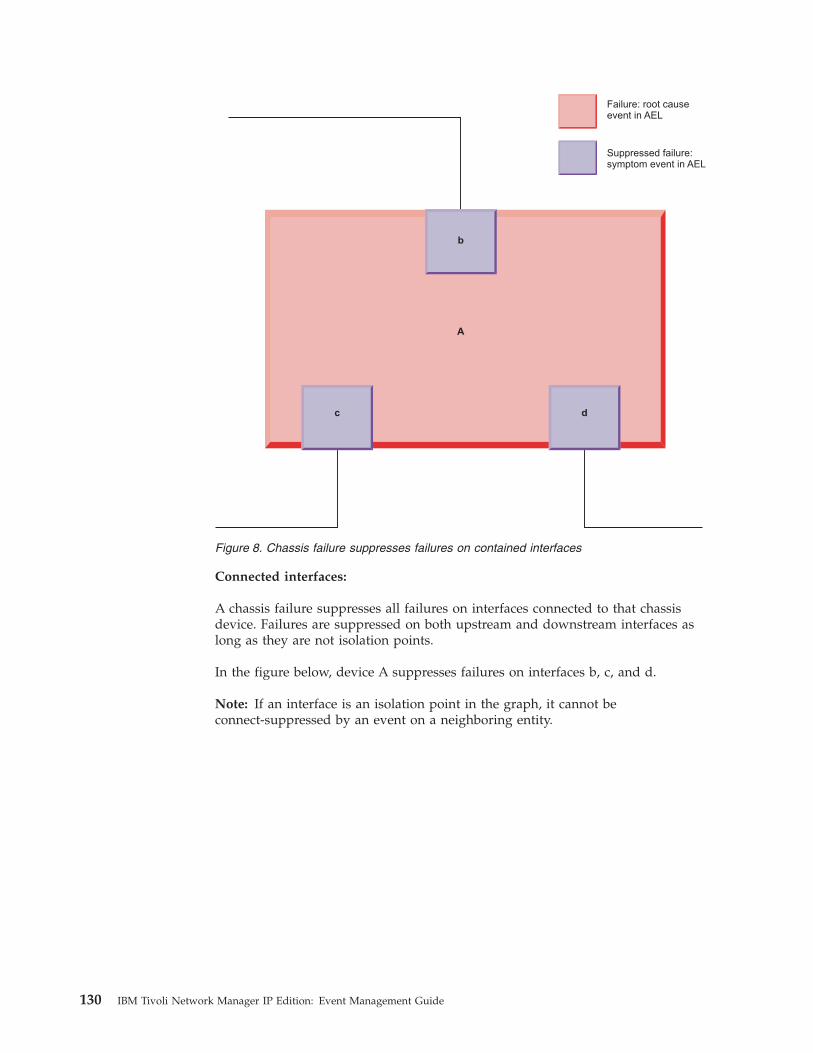
Connected interfaces:
A chassis failure suppresses all failures on interfaces connected to that chassisdevice. Failures are suppressed on both upstream and downstream interfaces aslong as they are not isolation points.
In the figure below, device A suppresses failures on interfaces b, c, and d.
Note: If an interface is an isolation point in the graph, it cannot beconnect-suppressed by an event on a neighboring entity.
A
d
b
c
Failure: root causeevent in AEL
Suppressed failure:symptom event in AEL
Figure 8. Chassis failure suppresses failures on contained interfaces
130 IBM Tivoli Network Manager IP Edition: Event Management Guide
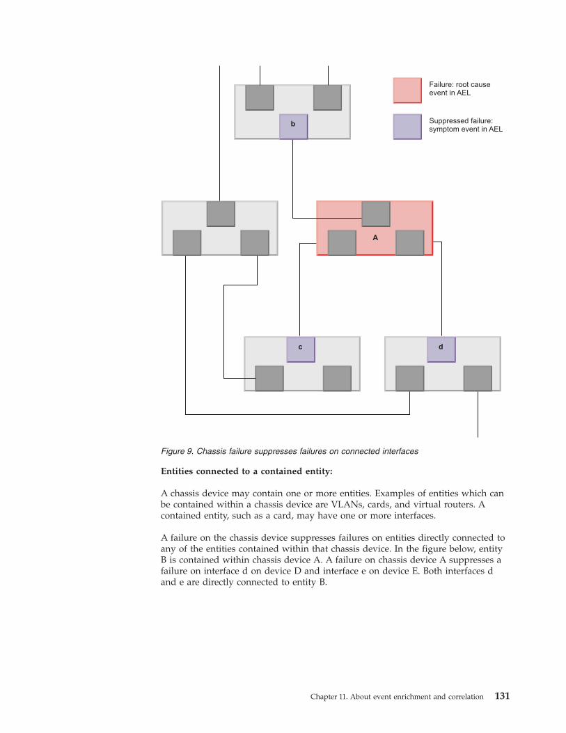
Entities connected to a contained entity:
A chassis device may contain one or more entities. Examples of entities which canbe contained within a chassis device are VLANs, cards, and virtual routers. Acontained entity, such as a card, may have one or more interfaces.
A failure on the chassis device suppresses failures on entities directly connected toany of the entities contained within that chassis device. In the figure below, entityB is contained within chassis device A. A failure on chassis device A suppresses afailure on interface d on device D and interface e on device E. Both interfaces dand e are directly connected to entity B.
A
c d
b
Failure: root causeevent in AEL
Suppressed failure:symptom event in AEL
Figure 9. Chassis failure suppresses failures on connected interfaces
Chapter 11. About event enrichment and correlation 131
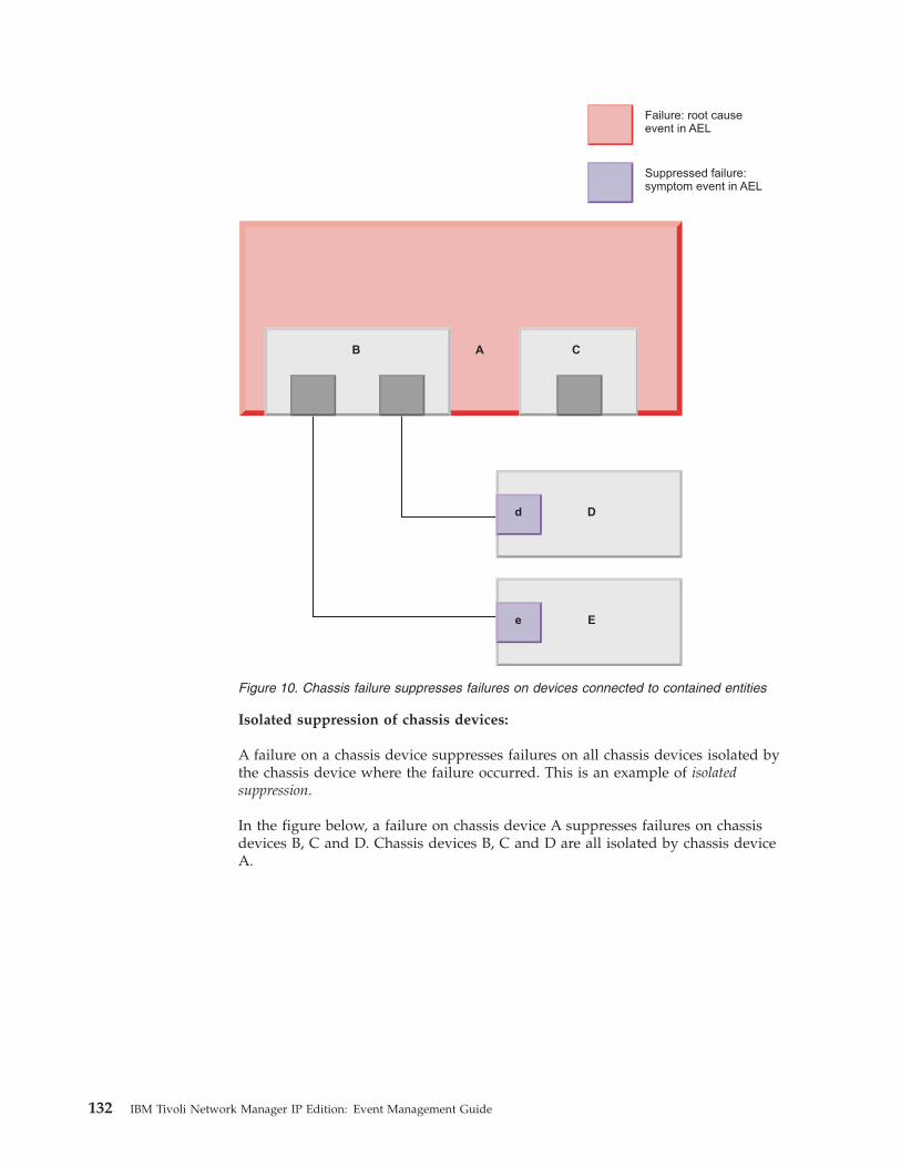
Isolated suppression of chassis devices:
A failure on a chassis device suppresses failures on all chassis devices isolated bythe chassis device where the failure occurred. This is an example of isolatedsuppression.
In the figure below, a failure on chassis device A suppresses failures on chassisdevices B, C and D. Chassis devices B, C and D are all isolated by chassis deviceA.
Failure: root causeevent in AEL
Suppressed failure:symptom event in AEL
D
E
d
e
B A C
Figure 10. Chassis failure suppresses failures on devices connected to contained entities
132 IBM Tivoli Network Manager IP Edition: Event Management Guide
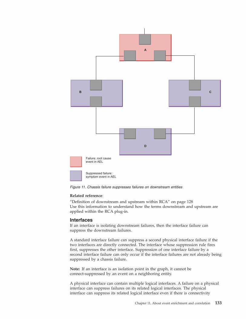
Related reference:“Definition of downstream and upstream within RCA” on page 128Use this information to understand how the terms downstream and upstream areapplied within the RCA plug-in.
InterfacesIf an interface is isolating downstream failures, then the interface failure cansuppress the downstream failures.
A standard interface failure can suppress a second physical interface failure if thetwo interfaces are directly connected. The interface whose suppression rule firesfirst, suppresses the other interface. Suppression of one interface failure by asecond interface failure can only occur if the interface failures are not already beingsuppressed by a chassis failure.
Note: If an interface is an isolation point in the graph, it cannot beconnect-suppressed by an event on a neighboring entity.
A physical interface can contain multiple logical interfaces. A failure on a physicalinterface can suppress failures on its related logical interfaces. The physicalinterface can suppress its related logical interface even if there is connectivity
A
D
CB
Failure: root causeevent in AEL
Suppressed failure:symptom event in AEL
Figure 11. Chassis failure suppresses failures on downstream entities
Chapter 11. About event enrichment and correlation 133
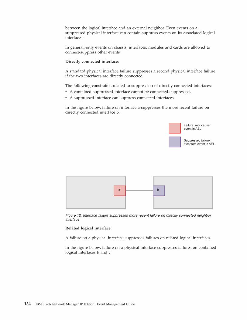
between the logical interface and an external neighbor. Even events on asuppressed physical interface can contain-suppress events on its associated logicalinterfaces.
In general, only events on chassis, interfaces, modules and cards are allowed toconnect-suppress other events
Directly connected interface:
A standard physical interface failure suppresses a second physical interface failureif the two interfaces are directly connected.
The following constraints related to suppression of directly connected interfaces:v A contained-suppressed interface cannot be connected suppressed.v A suppressed interface can suppress connected interfaces.
In the figure below, failure on interface a suppresses the more recent failure ondirectly connected interface b.
Related logical interface:
A failure on a physical interface suppresses failures on related logical interfaces.
In the figure below, failure on a physical interface suppresses failures on containedlogical interfaces b and c.
a b
Failure: root causeevent in AEL
Suppressed failure:symptom event in AEL
Figure 12. Interface failure suppresses more recent failure on directly connected neighborinterface
134 IBM Tivoli Network Manager IP Edition: Event Management Guide
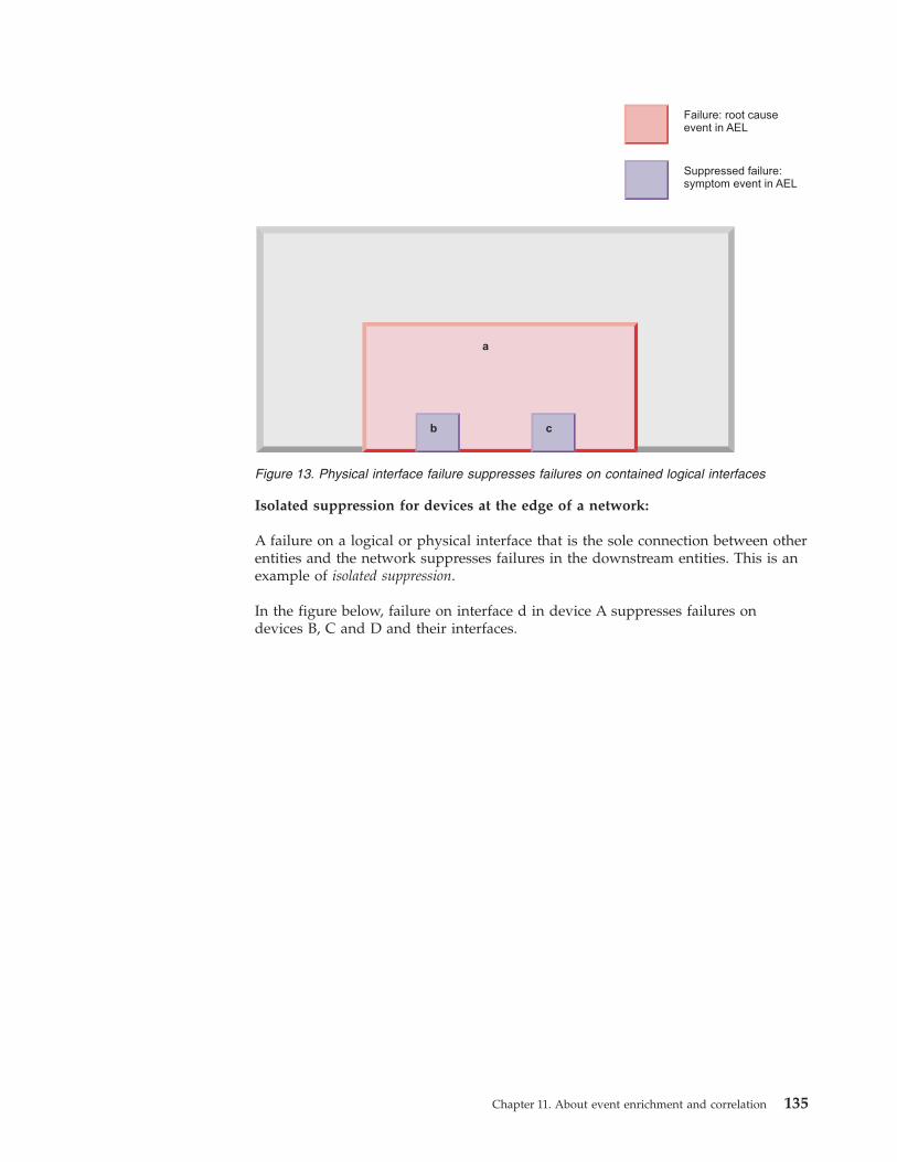
Isolated suppression for devices at the edge of a network:
A failure on a logical or physical interface that is the sole connection between otherentities and the network suppresses failures in the downstream entities. This is anexample of isolated suppression.
In the figure below, failure on interface d in device A suppresses failures ondevices B, C and D and their interfaces.
Failure: root causeevent in AEL
Suppressed failure:symptom event in AEL
a
b c
Figure 13. Physical interface failure suppresses failures on contained logical interfaces
Chapter 11. About event enrichment and correlation 135
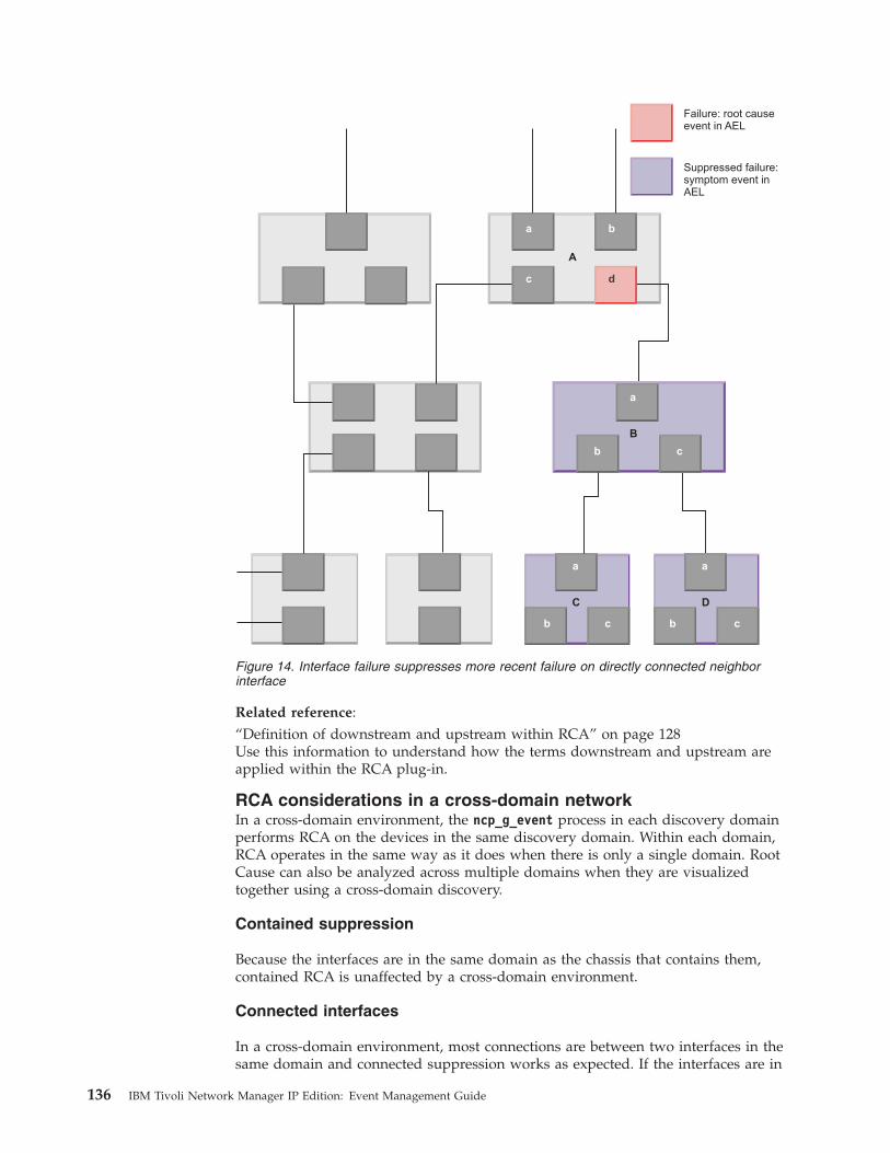
Related reference:“Definition of downstream and upstream within RCA” on page 128Use this information to understand how the terms downstream and upstream areapplied within the RCA plug-in.
RCA considerations in a cross-domain networkIn a cross-domain environment, the ncp_g_event process in each discovery domainperforms RCA on the devices in the same discovery domain. Within each domain,RCA operates in the same way as it does when there is only a single domain. RootCause can also be analyzed across multiple domains when they are visualizedtogether using a cross-domain discovery.
Contained suppression
Because the interfaces are in the same domain as the chassis that contains them,contained RCA is unaffected by a cross-domain environment.
Connected interfaces
In a cross-domain environment, most connections are between two interfaces in thesame domain and connected suppression works as expected. If the interfaces are in
a a
C D
b bc c
a
b
A
B
a b
c d
c
Failure: root causeevent in AEL
Suppressed failure:symptom event inAEL
Figure 14. Interface failure suppresses more recent failure on directly connected neighborinterface
136 IBM Tivoli Network Manager IP Edition: Event Management Guide
different domains, connected suppression does not associate the events at each endof the link.
Isolated suppression
Devices on the edge of the network, which have fewer connections, can becomeunreachable (isolated) from the poller entity if a device between them and thepoller entity fails. Events on these isolated devices are suppressed, as long as allisolated devices are in the same domain. When you partition your network, ensurethat groups of devices that are isolated are kept within the same domain.
SAE RCA
If a service, for example a VPN, consists of devices in two domains, then two SAEevents can be created for the same VPN, one in each domain.Related tasks:“Configuring the poller entity” on page 155When the Network Manager server is not within the scope of your networkdomain, or you have several domains, specify the IP address or DNS name of thepoller entity.Related reference:“Examples of root cause analysis” on page 127These examples show how the RCA process performs root cause analysis based onconsideration of different types of network devices and interfaces. The examplesare for illustrative purposes only and are meant to show only the principles thatRCA uses. RCA in larger networks is more complex.
Chapter 11. About event enrichment and correlation 137

138 IBM Tivoli Network Manager IP Edition: Event Management Guide
Chapter 12. Configuring event enrichment
You can configure the way an event is processed as it passes through the EventGateway.
Configuring extra event enrichmentYou can configure the Event Gateway to perform extra event enrichment. Thefollowing examples illustrate the kinds of information that can be added to anevent using event enrichment.
You can configure the Event Gateway to populate any field in the ObjectServeralerts.status table. You can populate an existing field or a customized field.
Note: The Event Gateway does not alter the alerts.status table. If you want tocreate a new field in the alerts.status table and have the Event Gateway populatethis new field, you must first alter the alerts.status table in the ObjectServer to addthe new field.
Modifications to the ObjectServer alerts.status tableThe Event Gateway does not create new fields in the alerts.status table. If you areconfiguring extra event enrichment then you might need to configure theObjectServer to add new fields to the alerts.status table.
The following examples describe typical custom event enrichment. Each examplespecifies whether any alerts.status table configuration is required prior toconfiguring the custom event enrichment.
Enriching a default event field that is not currently enrichedAn example of this is where you want to enrich the PhysicalPortalerts.status field. This is a field that exists by default in the alerts.statustable, and therefore there is no need to modify the ObjectServer.
Enriching a custom field that was already added earlier for a different purposeAn example of this is where you already have a field that is populated byone or more probes, and you want it populated for all events. In thisexample, some events that arrive via the monitor probe, from the poller,might have a populated EXTRAINFO_sysLocation field in the NCIM cachedata. You have already added an NmosLocation field to the ObjectServer,and this field is populated from the monitor probe where possible. It cannow be populated for all events. In this case there is no need to modify theObjectServer.
Performing any topology enrichment from the NCIM topology databaseIn this case you want to enrich the event with any of the data from NCIM.You must first modify the ObjectServer to add the new field or fields to thealerts.status table.
© Copyright IBM Corp. 2006, 2013 139

Example: Enriching an event with main node device locationYou can configure event enrichment so that the location of the main node deviceassociated with an event is added to a field in the event.
Consider which field in the ObjectServer to populate. There already is a defaultLocation field in the alerts.status table. This example assumes that you want topopulate this field, unless it is already populated. If you have a reason to create aseparate customized field to store the enriched location value, then you can add afield to the alerts.status table to store the main node device location; for example,NmosLocation. For information on how to add a custom field to an ObjectServertable, see the IBM Tivoli Netcool/OMNIbus Administration Guide.
The location of the main node device associated with an event is available in theNCIM topology database chassis table. This field can be accessed using NCIMcache, and is held in the ncimCache.entityData table.
For more information on the structure of NCIM cache tables and fields, see theIBM Tivoli Network Manager IP Edition Topology Database Reference.
The following steps explain how to configure this extra event enrichment.1. Edit the Event Gateway schema file, $NCHOME/etc/precision/
EventGatewaySchema.cfg, to allow the Event Gateway to update the new field.To do this, add the text in bold to the outgoing event filter. Remember to add acomma at the end of the line containing the NmosSerial field, before the linecontaining the new Location field.insert into config.ncp2nco(
FieldFilter)values(
["NmosCauseType","NmosDomainName","NmosEntityId","NmosManagedStatus","NmosObjInst","NmosSerial","Location"
]);
Note: Fields that are added to the outgoing event filter are automaticallyadded to the incoming field filter, config.nco2ncp, thus ensuring that thecurrent value of the field is retrieved. This allows the StandardEventEnrichmentstitcher in the next step to check the value of the InterfaceName field beforeupdating it. This technique ensures that the Event Gateway does not keepupdating the same value.
2. Edit the Event Gateway stitchers to retrieve the location information from thetopology database and to populate the Location field. One way to do this is toadd the following code to the StandardEventEnrichment stitcher. Adding thiscode ensures that this procedure is performed for all topology events that arematched to an entity. Add this code to the stitcher immediately before the finalline, the call to GwEnrichEvent( enrichedFields ). For more information on theGwEnrichEvent() stitcher rule, see the IBM Tivoli Network Manager IP EditionLanguage Reference.
140 IBM Tivoli Network Manager IP Edition: Event Management Guide
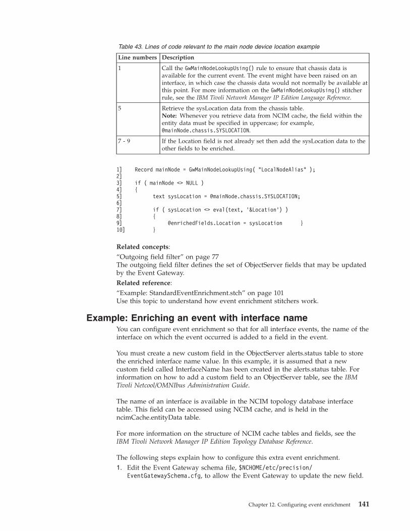
Table 43. Lines of code relevant to the main node device location example
Line numbers Description
1 Call the GwMainNodeLookupUsing() rule to ensure that chassis data isavailable for the current event. The event might have been raised on aninterface, in which case the chassis data would not normally be available atthis point. For more information on the GwMainNodeLookupUsing() stitcherrule, see the IBM Tivoli Network Manager IP Edition Language Reference.
5 Retrieve the sysLocation data from the chassis table.Note: Whenever you retrieve data from NCIM cache, the field within theentity data must be specified in uppercase; for example,@mainNode.chassis.SYSLOCATION.
7 - 9 If the Location field is not already set then add the sysLocation data to theother fields to be enriched.
1]2]3]4]5]6]7]8]9]10]
Record mainNode = GwMainNodeLookupUsing( "LocalNodeAlias" );
if ( mainNode <> NULL ){
text sysLocation = @mainNode.chassis.SYSLOCATION;
if ( sysLocation <> eval(text, ’&Location’) ){
@enrichedFields.Location = sysLocation }}
Related concepts:“Outgoing field filter” on page 77The outgoing field filter defines the set of ObjectServer fields that may be updatedby the Event Gateway.Related reference:“Example: StandardEventEnrichment.stch” on page 101Use this topic to understand how event enrichment stitchers work.
Example: Enriching an event with interface nameYou can configure event enrichment so that for all interface events, the name of theinterface on which the event occurred is added to a field in the event.
You must create a new custom field in the ObjectServer alerts.status table to storethe enriched interface name value. In this example, it is assumed that a newcustom field called InterfaceName has been created in the alerts.status table. Forinformation on how to add a custom field to an ObjectServer table, see the IBMTivoli Netcool/OMNIbus Administration Guide.
The name of an interface is available in the NCIM topology database interfacetable. This field can be accessed using NCIM cache, and is held in thencimCache.entityData table.
For more information on the structure of NCIM cache tables and fields, see theIBM Tivoli Network Manager IP Edition Topology Database Reference.
The following steps explain how to configure this extra event enrichment.1. Edit the Event Gateway schema file, $NCHOME/etc/precision/
EventGatewaySchema.cfg, to allow the Event Gateway to update the new field.
Chapter 12. Configuring event enrichment 141
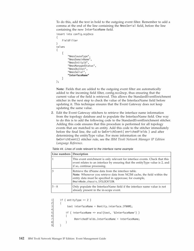
To do this, add the text in bold to the outgoing event filter. Remember to add acomma at the end of the line containing the NmosSerial field, before the linecontaining the new InterfaceName field.insert into config.ncp2nco(
FieldFilter)values(
["NmosCauseType","NmosDomainName","NmosEntityId","NmosManagedStatus","NmosObjInst","NmosSerial","InterfaceName"
]);
Note: Fields that are added to the outgoing event filter are automaticallyadded to the incoming field filter, config.nco2ncp, thus ensuring that thecurrent value of the field is retrieved. This allows the StandardEventEnrichmentstitcher in the next step to check the value of the InterfaceName field beforeupdating it. This technique ensures that the Event Gateway does not keepupdating the same value.
2. Edit the Event Gateway stitchers to retrieve the interface name informationfrom the topology database and to populate the InterfaceName field. One wayto do this is to add the following code to the StandardEventEnrichment stitcher.Adding this code ensures that this procedure is performed for all topologyevents that are matched to an entity. Add this code to the stitcher immediatelybefore the final line, the call to GwEnrichEvent( enrichedFields ) and afterdetermining the entityType value. For more information on theGwEnrichEvent() stitcher rule, see the IBM Tivoli Network Manager IP EditionLanguage Reference.
Table 44. Lines of code relevant to the interface name example
Line numbers Description
1 This event enrichment is only relevant for interface events. Check that thisevent relates to an interface by ensuring that the entityType value is 2, andif so, continue processing.
3 Retrieve the ifName data from the interface table.Note: Whenever you retrieve data from NCIM cache, the field within theentity data must be specified in uppercase; for example,@mainNode.chassis.SYSLOCATION.
5 - 8 Only populate the InterfaceName field if the interface name value is notalready present in the in-scope event.
1]2]3]4]5]6]7]8]9]
if ( entityType == 2 ){
text interfaceName = @entity.interface.IFNAME;
if ( interfaceName <> eval(text, ’&InterfaceName’) ){
@enrichedFields.InterfaceName = interfaceName;}
}
142 IBM Tivoli Network Manager IP Edition: Event Management Guide
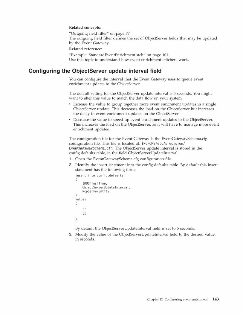
Related concepts:“Outgoing field filter” on page 77The outgoing field filter defines the set of ObjectServer fields that may be updatedby the Event Gateway.Related reference:“Example: StandardEventEnrichment.stch” on page 101Use this topic to understand how event enrichment stitchers work.
Configuring the ObjectServer update interval fieldYou can configure the interval that the Event Gateway uses to queue eventenrichment updates to the ObjectServer.
The default setting for the ObjectServer update interval is 5 seconds. You mightwant to alter this value to match the data flow on your system.v Increase the value to group together more event enrichment updates in a single
ObjectServer update. This decreases the load on the ObjectServer but increasesthe delay in event enrichment updates on the ObjectServer
v Decrease the value to speed up event enrichment updates to the ObjectServer.This increases the load on the ObjectServer, as it will have to manage more eventenrichment updates.
The configuration file for the Event Gateway is the EventGatewaySchema.cfgconfiguration file. This file is located at: $NCHOME/etc/precision/EventGatewaySchema.cfg. The ObjectServer update interval is stored in theconfig.defaults table, in the field ObjectServerUpdateInterval.1. Open the EventGatewaySchema.cfg configuration file.2. Identify the insert statement into the config.defaults table. By default this insert
statement has the following form:insert into config.defaults(
IDUCFlushTime,ObjectServerUpdateInterval,NcpServerEntity
)values(
5,5,""
);
By default the ObjectServerUpdateInterval field is set to 5 seconds.3. Modify the value of the ObjectServerUpdateInterval field to the desired value,
in seconds.
Chapter 12. Configuring event enrichment 143
Related concepts:“Outgoing Event Gateway queue” on page 78The outgoing Event Gateway queue receives enriched events from the EventGateway stitchers (main event enrichment) and from the plug-ins. In order tominimize the number of updates and hence minimize the load on the ObjectServer,updates to the Object Server are placed in a queue, aggregated, and sent to theObjectServer at a specified interval. The default is 5 seconds.Related reference:“config.defaults table” on page 220The config.defaults table contains general configuration data for the EventGateway.
Using the OQL service provider to log into the Event Gatewaydatabases
You must log into the databases using the object query language (OQL) serviceprovider and the EventGateway service name to query the gateway databases.
The command-line example below logs in to the NcoGate service for the EventGateway, which is running in the NCOMS domain.ncp_oql -domain NCOMS -service EventGateway
User authentication for the OQL Service Provider is off by default. If authenticationhas been turned on, type a valid username and password at the prompt.
Querying the ObjectServerYou can use the OQL Service Provider to query the ObjectServer.
The OQL Service Provider command-line example below logs in to theObjectServer service, which is running in the NCOMS domain on an ObjectServercalled NCOMS.ncp_oql -domain NCOMS -service ObjectServer -server NCOMS -username netcool
User authentication for the OQL Service Provider is off by default. If authenticationhas been turned on, type a valid username and password at the prompt.
Note: The -server argument is optional. If this argument is not specified then theserver configured in the $NCHOME/etc/precision/ConfigItnm.cfg file is used.
Querying the NCIM databaseYou can use the OQL Service Provider to query the NCIM database.
The OQL Service Provider command-line example below logs in to theNCMONITOR schema within the NCIM service, which is running in the NCOMSdomain. This is useful if you want to access a table in the NCMONITOR schema;for example, the activeEvent table.ncp_oql -domain NCOMS -service Ncim -dbId NCMONITOR
User authentication for the OQL Service Provider is off by default. If authenticationhas been turned on, type a valid username and password at the prompt.
Note: The -dbId argument is optional.
144 IBM Tivoli Network Manager IP Edition: Event Management Guide
Resynchronizing events with the ObjectServerIssue the SIGHUP command to the Event Gateway to change the configuration ofthe Event Gateway.
Type this command: kill -HUP PID, where PID is the process ID of the EventGateway.
The Event Gateway checks the timestamp on the configuration file. If theconfiguration file is modified, then the Event Gateway reads the configuration fileagain to process any configuration changes.
Note: This command also resynchronizes all events with the Event Gateway.
Processing steps for the SIGHUP command
The processing of the SIGHUP command is described in the following steps:1. Event Gateway receives an HUP command.2. Event Gateway stops listening for events on the ObjectServer IDUC channel.3. Event Gateway empties its current cache of events. This cache is used to
determine event state.4. Event Gateway sends all its plug-ins a synthetic resync start event5. RCA plug-in cleans out the mojo.events database table and redraws the graph
based on data in NCIM cache.
Note: The RCA plug-in does not reread the RCASchema.cfg configuration fileor the RCA stitchers at this point.
6. Event Gateway retrieves all events from the Object Server, in the same way thatit would at startup.
7. Event Gateway processes all events in the same way that it would at startupand passes any relevant events to the plug-ins.
8. Event Gateway sends a resync end event to its plug-ins.9. Event Gateway resumes listening for events on the ObjectServer IDUC channel,Related tasks:Chapter 14, “Configuring root-cause analysis,” on page 155You can configure the RCA plug-in.
Chapter 12. Configuring event enrichment 145

146 IBM Tivoli Network Manager IP Edition: Event Management Guide
Chapter 13. Configuring Event Gateway plug-ins
You can configure Event Gateway plug-ins. You can also view currently enabledplug-ins.
Enabling and disabling pluginsYou can enable and disable plug-ins.
Use the ncp_gwplugins.pl script to enable and disable plugins. The script islocated at $NCHOME/precision/scripts/perl/scripts/ncp_gwplugins.pl.
To run the script to enable event map subscriptions, issue a command similar tothe following. This example enables the zNetView plug-in in all domains.$NCHOME/precision/bin/ncp_perl $NCHOME/precision/scripts/perl/scripts/ncp_gwplugins.pl -domain NCOMS -plugin zNetView -enable -global
Command-line options
The following table describes the command-line options for the ncp_gwplugins.plscript used in this example. For help, run the script as follows:v For a brief list of the available options, run the command without any options.v For a full set of command line options, run the script with the -help option.
Table 45. ncp_gwplugins.pl command-line options
Command-line option Description
-domain DomainName Mandatory; the name of a domain related tothe plug-in. This domain is used to enablethe script to read the relevant DbLogins,cfgfile in order to connect to and update therelevant Event Gateway plug-in databases.
-plugin PluginName Name of the plug-in.Note: You can only run the script for oneplug-in at a time.Plug-in names for use inthis command line option are as follows. Ifthe plug-in name is made up of more thanone word, then the name must be enclosedin double quotes; for example: "AdaptivePolling".
v Adaptive Polling
v Disco
v Failover
v ITNCM
v PostNcimProcessing
v RCA
v SAE IP Path
v SAE ITNM Service
v SAE MPLS VPN
v zNetView
-disable Disables the specified plug-in.
© Copyright IBM Corp. 2006, 2013 147
Table 45. ncp_gwplugins.pl command-line options (continued)
Command-line option Description
-enable Enables the specified plug-in.
-global Enables plug-ins in all domains. If this is notspecified, then the plug-in is enabled only inthe domain specified using the -domainparameter.
Related reference:“Plugin descriptions” on page 106Use this information to understand what each Event Gateway plugin does.“ncp_g_event plug-in database tables in ncmonitor” on page 229Use this information to understand which Event Gateway configuration tables areavailable in the ncmonitor database and what type of information each tablecontains. Most of these tables relate to Event Gateway plug-in configuration.
Listing plug-in informationYou can list information on Event Gateway plug-ins. For example, you can list theevent maps and event states that each plug-in subscribes to.
Use the ncp_gwplugins.pl script to list plug-in information, The script is located at$NCHOME/precision/scripts/perl/scripts/ncp_gwplugins.pl.
To run the script to list event map subscriptions, issue a command similar to thefollowing. This example lists all event maps and event states subscribed to by theDisco plug-in.$NCHOME/precision/bin/ncp_perl$NCHOME/precision/scripts/perl/scripts/ncp_gwplugins.pl -domain NCOMS -plugin Disco
Command-line options
The following table describes the command-line options for the ncp_gwplugins.plscript used in this example. For help, run the script as follows:v For a brief list of the available options, run the command without any options.v For a full set of command line options, run the script with the -help option.
Table 46. ncp_gwplugins.pl command-line options
Command-line option Description
-domain DomainName Mandatory; the name of a domain related tothe plug-in. This domain is used to enablethe script to read the relevant DbLogins,cfgfile in order to connect to the relevant EventGateway plug-in databases.
148 IBM Tivoli Network Manager IP Edition: Event Management Guide
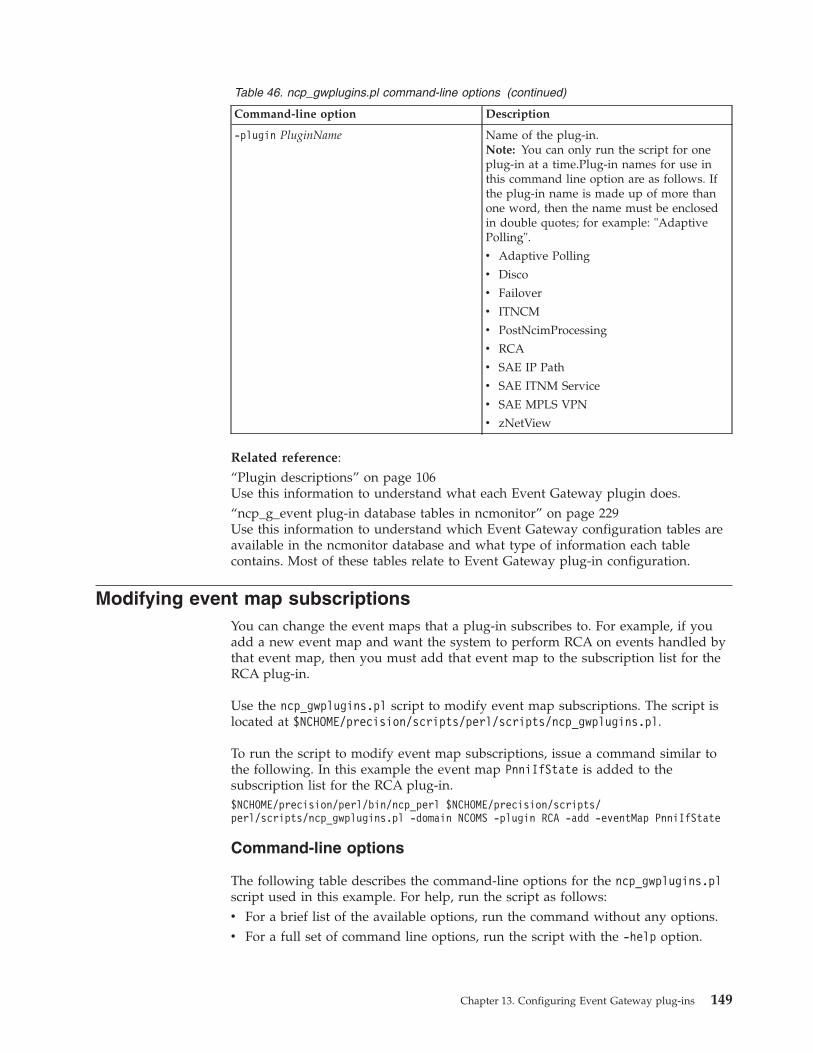
Table 46. ncp_gwplugins.pl command-line options (continued)
Command-line option Description
-plugin PluginName Name of the plug-in.Note: You can only run the script for oneplug-in at a time.Plug-in names for use inthis command line option are as follows. Ifthe plug-in name is made up of more thanone word, then the name must be enclosedin double quotes; for example: "AdaptivePolling".
v Adaptive Polling
v Disco
v Failover
v ITNCM
v PostNcimProcessing
v RCA
v SAE IP Path
v SAE ITNM Service
v SAE MPLS VPN
v zNetView
Related reference:“Plugin descriptions” on page 106Use this information to understand what each Event Gateway plugin does.“ncp_g_event plug-in database tables in ncmonitor” on page 229Use this information to understand which Event Gateway configuration tables areavailable in the ncmonitor database and what type of information each tablecontains. Most of these tables relate to Event Gateway plug-in configuration.
Modifying event map subscriptionsYou can change the event maps that a plug-in subscribes to. For example, if youadd a new event map and want the system to perform RCA on events handled bythat event map, then you must add that event map to the subscription list for theRCA plug-in.
Use the ncp_gwplugins.pl script to modify event map subscriptions. The script islocated at $NCHOME/precision/scripts/perl/scripts/ncp_gwplugins.pl.
To run the script to modify event map subscriptions, issue a command similar tothe following. In this example the event map PnniIfState is added to thesubscription list for the RCA plug-in.$NCHOME/precision/perl/bin/ncp_perl $NCHOME/precision/scripts/perl/scripts/ncp_gwplugins.pl -domain NCOMS -plugin RCA -add -eventMap PnniIfState
Command-line options
The following table describes the command-line options for the ncp_gwplugins.plscript used in this example. For help, run the script as follows:v For a brief list of the available options, run the command without any options.v For a full set of command line options, run the script with the -help option.
Chapter 13. Configuring Event Gateway plug-ins 149
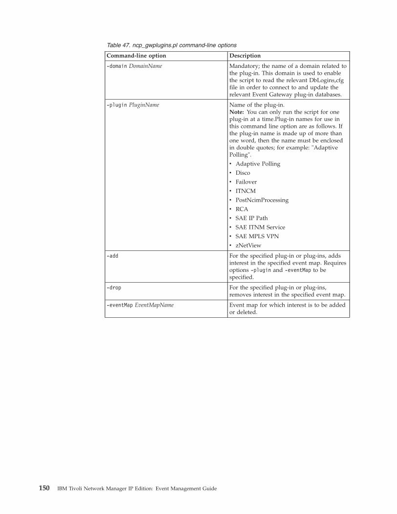
Table 47. ncp_gwplugins.pl command-line options
Command-line option Description
-domain DomainName Mandatory; the name of a domain related tothe plug-in. This domain is used to enablethe script to read the relevant DbLogins,cfgfile in order to connect to and update therelevant Event Gateway plug-in databases.
-plugin PluginName Name of the plug-in.Note: You can only run the script for oneplug-in at a time.Plug-in names for use inthis command line option are as follows. Ifthe plug-in name is made up of more thanone word, then the name must be enclosedin double quotes; for example: "AdaptivePolling".
v Adaptive Polling
v Disco
v Failover
v ITNCM
v PostNcimProcessing
v RCA
v SAE IP Path
v SAE ITNM Service
v SAE MPLS VPN
v zNetView
-add For the specified plug-in or plug-ins, addsinterest in the specified event map. Requiresoptions -plugin and -eventMap to bespecified.
-drop For the specified plug-in or plug-ins,removes interest in the specified event map.
-eventMap EventMapName Event map for which interest is to be addedor deleted.
150 IBM Tivoli Network Manager IP Edition: Event Management Guide
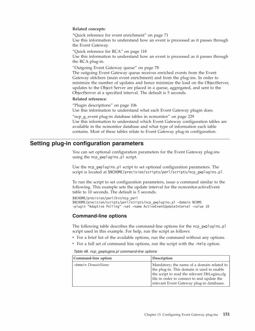
Related concepts:“Quick reference for event enrichment” on page 71Use this information to understand how an event is processed as it passes throughthe Event Gateway.“Quick reference for RCA” on page 118Use this information to understand how an event is processed as it passes throughthe RCA plug-in.“Outgoing Event Gateway queue” on page 78The outgoing Event Gateway queue receives enriched events from the EventGateway stitchers (main event enrichment) and from the plug-ins. In order tominimize the number of updates and hence minimize the load on the ObjectServer,updates to the Object Server are placed in a queue, aggregated, and sent to theObjectServer at a specified interval. The default is 5 seconds.Related reference:“Plugin descriptions” on page 106Use this information to understand what each Event Gateway plugin does.“ncp_g_event plug-in database tables in ncmonitor” on page 229Use this information to understand which Event Gateway configuration tables areavailable in the ncmonitor database and what type of information each tablecontains. Most of these tables relate to Event Gateway plug-in configuration.
Setting plug-in configuration parametersYou can set optional configuration parameters for the Event Gateway plug-insusing the ncp_gwplugins.pl script.
Use the ncp_gwplugins.pl script to set optional configuration parameters. Thescript is located at $NCHOME/precision/scripts/perl/scripts/ncp_gwplugins.pl.
To run the script to set configuration parameters, issue a command similar to thefollowing. This example sets the update interval for the ncmonitor.activeEventtable to 10 seconds. The default is 5 seconds.$NCHOME/precision/perl/bin/ncp_perl$NCHOME/precision/scripts/perl/scripts/ncp_gwplugins.pl -domain NCOMS-plugin "Adaptive Polling" -set -name ActiveEventUpdateInterval -value 10
Command-line options
The following table describes the command-line options for the ncp_gwplugins.plscript used in this example. For help, run the script as follows:v For a brief list of the available options, run the command without any options.v For a full set of command line options, run the script with the -help option.
Table 48. ncp_gwplugins.pl command-line options
Command-line option Description
-domain DomainName Mandatory; the name of a domain related tothe plug-in. This domain is used to enablethe script to read the relevant DbLogins,cfgfile in order to connect to and update therelevant Event Gateway plug-in databases.
Chapter 13. Configuring Event Gateway plug-ins 151
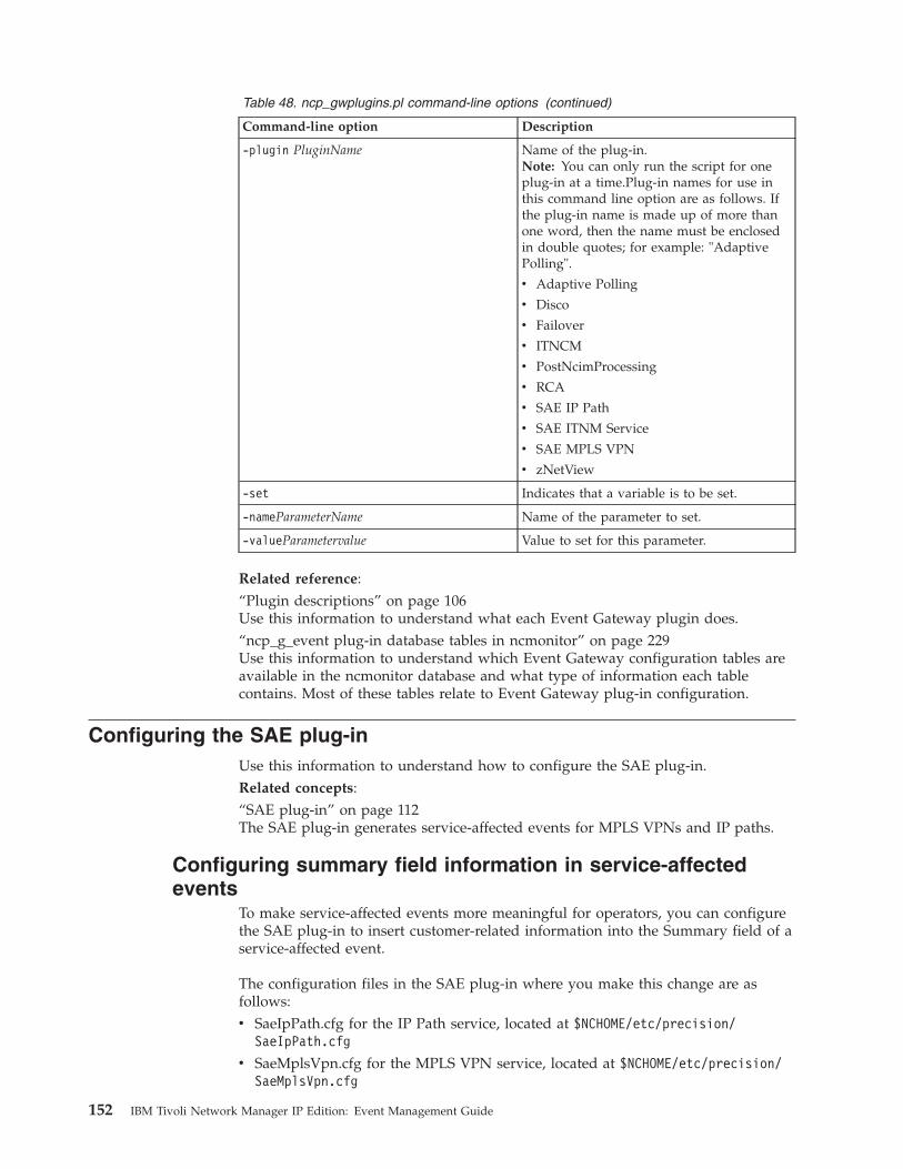
Table 48. ncp_gwplugins.pl command-line options (continued)
Command-line option Description
-plugin PluginName Name of the plug-in.Note: You can only run the script for oneplug-in at a time.Plug-in names for use inthis command line option are as follows. Ifthe plug-in name is made up of more thanone word, then the name must be enclosedin double quotes; for example: "AdaptivePolling".
v Adaptive Polling
v Disco
v Failover
v ITNCM
v PostNcimProcessing
v RCA
v SAE IP Path
v SAE ITNM Service
v SAE MPLS VPN
v zNetView
-set Indicates that a variable is to be set.
-nameParameterName Name of the parameter to set.
-valueParametervalue Value to set for this parameter.
Related reference:“Plugin descriptions” on page 106Use this information to understand what each Event Gateway plugin does.“ncp_g_event plug-in database tables in ncmonitor” on page 229Use this information to understand which Event Gateway configuration tables areavailable in the ncmonitor database and what type of information each tablecontains. Most of these tables relate to Event Gateway plug-in configuration.
Configuring the SAE plug-inUse this information to understand how to configure the SAE plug-in.Related concepts:“SAE plug-in” on page 112The SAE plug-in generates service-affected events for MPLS VPNs and IP paths.
Configuring summary field information in service-affectedevents
To make service-affected events more meaningful for operators, you can configurethe SAE plug-in to insert customer-related information into the Summary field of aservice-affected event.
The configuration files in the SAE plug-in where you make this change are asfollows:v SaeIpPath.cfg for the IP Path service, located at $NCHOME/etc/precision/
SaeIpPath.cfg
v SaeMplsVpn.cfg for the MPLS VPN service, located at $NCHOME/etc/precision/SaeMplsVpn.cfg
152 IBM Tivoli Network Manager IP Edition: Event Management Guide
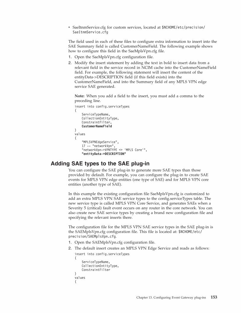
v SaeItnmService.cfg for custom services, located at $NCHOME/etc/precision/SaeItnmService.cfg
The field used in each of these files to configure extra information to insert into theSAE Summary field is called CustomerNameField. The following example showshow to configure this field in the SaeMplsVpn.cfg file.1. Open the SaeMplsVpn.cfg configuration file.2. Modify the insert statement by adding the text in bold to insert data from a
relevant field in the service record in NCIM cache into the CustomerNameFieldfield. For example, the following statement will insert the content of theentityData->DESCRIPTION field (if this field exists) into theCustomerNameField, and into the Summary field of any MPLS VPN edgeservice SAE generated.
Note: When you add a field to the insert, you must add a comma to thepreceding line.insert into config.serviceTypes(
ServiceTypeName,CollectionEntityType,ConstraintFilter,CustomerNameField
)values(
"MPLSVPNEdgeService",17 -- "networkVpn","networkVpn->VPNTYPE <> ’MPLS Core’","entityData->DESCRIPTION"
Adding SAE types to the SAE plug-inYou can configure the SAE plug-in to generate more SAE types than thoseprovided by default. For example, you can configure the plug-in to create SAEevents for MPLS VPN edge entities (one type of SAE) and for MPLS VPN coreentities (another type of SAE).
In this example the existing configuration file SaeMplsVpn.cfg is customized toadd an extra MPLS VPN SAE service types to the config.serviceTypes table. Thenew service type is called MPLS VPN Core Service, and generates SAEs when aSeverity 5 (critical) fault event occurs on any router in the core network. You canalso create new SAE service types by creating a brand new configuration file andspecifying the relevant inserts there.
The configuration file for the MPLS VPN SAE service types in the SAE plug-in isthe SAEMplsVpn.cfg configuration file. This file is located at: $NCHOME/etc/precision/SAEMplsVpn.cfg.1. Open the SAEMplsVpn.cfg configuration file.2. The default insert creates an MPLS VPN Edge Service and reads as follows:
insert into config.serviceTypes(
ServiceTypeName,CollectionEntityType,ConstraintFilter
)values(
Chapter 13. Configuring Event Gateway plug-ins 153
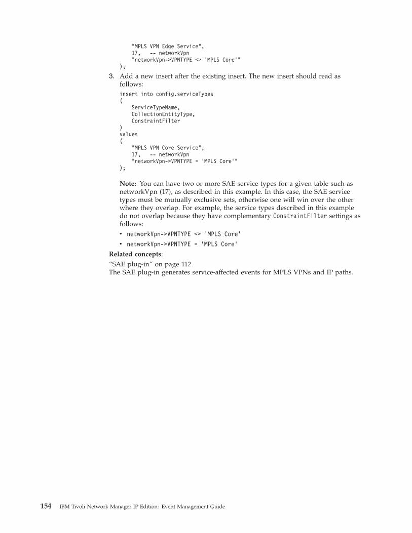
"MPLS VPN Edge Service",17, -- networkVpn"networkVpn->VPNTYPE <> ’MPLS Core’"
);
3. Add a new insert after the existing insert. The new insert should read asfollows:insert into config.serviceTypes(
ServiceTypeName,CollectionEntityType,ConstraintFilter
)values(
"MPLS VPN Core Service",17, -- networkVpn"networkVpn->VPNTYPE = ’MPLS Core’"
);
Note: You can have two or more SAE service types for a given table such asnetworkVpn (17), as described in this example. In this case, the SAE servicetypes must be mutually exclusive sets, otherwise one will win over the otherwhere they overlap. For example, the service types described in this exampledo not overlap because they have complementary ConstraintFilter settings asfollows:v networkVpn->VPNTYPE <> ’MPLS Core’
v networkVpn->VPNTYPE = ’MPLS Core’
Related concepts:“SAE plug-in” on page 112The SAE plug-in generates service-affected events for MPLS VPNs and IP paths.
154 IBM Tivoli Network Manager IP Edition: Event Management Guide
Chapter 14. Configuring root-cause analysis
You can configure the RCA plug-in.Related reference:“Resynchronizing events with the ObjectServer” on page 145Issue the SIGHUP command to the Event Gateway to change the configuration ofthe Event Gateway.
Configuring the poller entityWhen the Network Manager server is not within the scope of your networkdomain, or you have several domains, specify the IP address or DNS name of thepoller entity.
The poller entity is a designated node in the topology from which RCA iscalculated. By default, the poller entity is the same as the server where theNetwork Manager core components are installed.
Define one poller entity for each discovery domain. The poller entity must exist inthe discovered network topology for the domain in which it is defined. If theserver where Network Manager is installed is itself not in the topology, set thepoller entity to the nearest node that is within the topology.
For effective downstream and isolated suppression, set the poller entity to be theserver from where the network is polled, or as close to that server as possible.
The configuration file for the Event Gateway is theEventGatewaySchema.DOMAIN.cfg configuration file, where DOMAIN is the nameof the domain in which the Event Gateway is running. This file is located at:NCHOME/etc/precision/. The poller entity value is stored in the config.defaultstable, in the field NcpServerEntity.1. Open the EventGatewaySchema.DOMAIN.cfg configuration file.2. Identify the insert statement into the config.defaults table. By default this insert
statement has the following form:insert into config.defaults(
IDUCFlushTime,ObjectServerUpdateInterval,NcimHandleCount,NcpServerEntity
)values(
5,5,1""
);
By default the NcpServerEntity field is empty. In this case, the Event Gatewaysearches the topology using the IP address or the addresses of the local host itis running on.
© Copyright IBM Corp. 2006, 2013 155
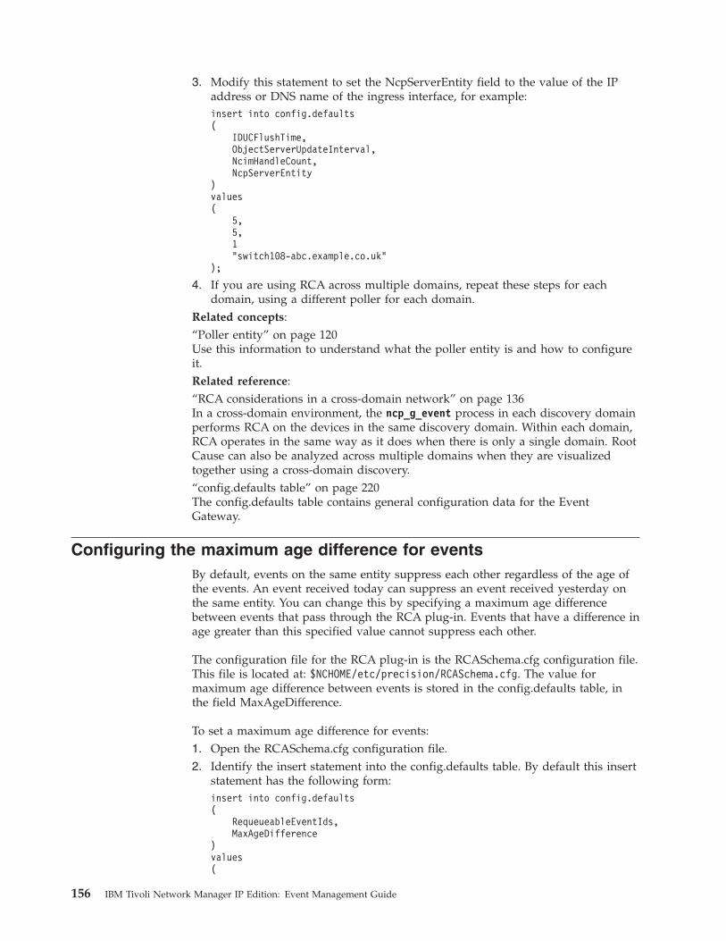
3. Modify this statement to set the NcpServerEntity field to the value of the IPaddress or DNS name of the ingress interface, for example:insert into config.defaults(
IDUCFlushTime,ObjectServerUpdateInterval,NcimHandleCount,NcpServerEntity
)values(
5,5,1"switch108-abc.example.co.uk"
);
4. If you are using RCA across multiple domains, repeat these steps for eachdomain, using a different poller for each domain.
Related concepts:“Poller entity” on page 120Use this information to understand what the poller entity is and how to configureit.Related reference:“RCA considerations in a cross-domain network” on page 136In a cross-domain environment, the ncp_g_event process in each discovery domainperforms RCA on the devices in the same discovery domain. Within each domain,RCA operates in the same way as it does when there is only a single domain. RootCause can also be analyzed across multiple domains when they are visualizedtogether using a cross-domain discovery.“config.defaults table” on page 220The config.defaults table contains general configuration data for the EventGateway.
Configuring the maximum age difference for eventsBy default, events on the same entity suppress each other regardless of the age ofthe events. An event received today can suppress an event received yesterday onthe same entity. You can change this by specifying a maximum age differencebetween events that pass through the RCA plug-in. Events that have a difference inage greater than this specified value cannot suppress each other.
The configuration file for the RCA plug-in is the RCASchema.cfg configuration file.This file is located at: $NCHOME/etc/precision/RCASchema.cfg. The value formaximum age difference between events is stored in the config.defaults table, inthe field MaxAgeDifference.
To set a maximum age difference for events:1. Open the RCASchema.cfg configuration file.2. Identify the insert statement into the config.defaults table. By default this insert
statement has the following form:insert into config.defaults(
RequeueableEventIds,MaxAgeDifference
)values(
156 IBM Tivoli Network Manager IP Edition: Event Management Guide

[’NmosPingFail’,’NmosSnmpPollFail’
],0
);
By default the value for MaxAgeDifference is 0. This means that the feature isturned off.
3. Modify this statement to set the MaxAgeDifference field to a desired value inminutes.
Tip: For example, set the MaxAgeDifference field to a value of 15 to configurethe system so that events on the same entity that have a difference in agegreater than fifteen minutes cannot suppress each other.
Related reference:“config.defaults database table” on page 226The config.defaults database table stores configuration data for the RCA plug-inevent queue.
Chapter 14. Configuring root-cause analysis 157

158 IBM Tivoli Network Manager IP Edition: Event Management Guide
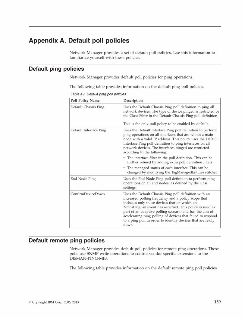
Appendix A. Default poll policies
Network Manager provides a set of default poll policies. Use this information tofamiliarize yourself with these policies.
Default ping policiesNetwork Manager provides default poll policies for ping operations.
The following table provides information on the default ping poll policies.
Table 49. Default ping poll policies
Poll Policy Name Description
Default Chassis Ping Uses the Default Chassis Ping poll definition to ping allnetwork devices. The type of device pinged is restricted bythe Class Filter in the Default Chassis Ping poll definition.
This is the only poll policy to be enabled by default.
Default Interface Ping Uses the Default Interface Ping poll definition to performping operations on all interfaces that are within a mainnode with a valid IP address. This policy uses the DefaultInterface Ping poll definition to ping interfaces on allnetwork devices. The interfaces pinged are restrictedaccording to the following:
v The interface filter in the poll definition. This can befurther refined by adding extra poll definition filters.
v The managed status of each interface. This can bechanged by modifying the TagManagedEntities stitcher.
End Node Ping Uses the End Node Ping poll definition to perform pingoperations on all end nodes, as defined by the classsettings.
ConfirmDeviceDown Uses the Default Chassis Ping poll definition with anincreased polling frequency and a policy scope thatincludes only those devices that on which anNmosPingFail event has occurred. This policy is used aspart of an adaptive polling scenario and has the aim ofaccelerating ping polling of devices that failed to respondto a ping poll in order to identify devices that are reallydown.
Default remote ping policiesNetwork Manager provides default poll policies for remote ping operations. Thesepolls use SNMP write operations to control vendor-specific extensions to theDISMAN-PING-MIB.
The following table provides information on the default remote ping poll policies.
© Copyright IBM Corp. 2006, 2013 159
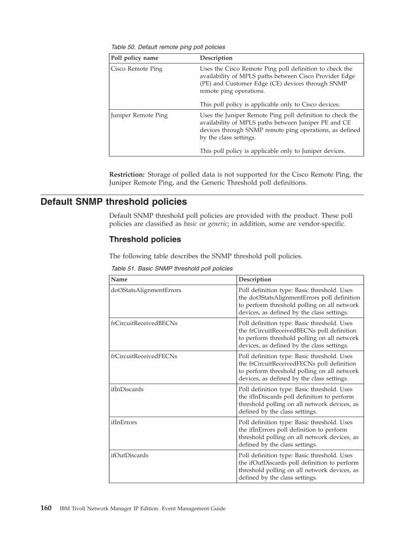
Table 50. Default remote ping poll policies
Poll policy name Description
Cisco Remote Ping Uses the Cisco Remote Ping poll definition to check theavailability of MPLS paths between Cisco Provider Edge(PE) and Customer Edge (CE) devices through SNMPremote ping operations.
This poll policy is applicable only to Cisco devices.
Juniper Remote Ping Uses the Juniper Remote Ping poll definition to check theavailability of MPLS paths between Juniper PE and CEdevices through SNMP remote ping operations, as definedby the class settings.
This poll policy is applicable only to Juniper devices.
Restriction: Storage of polled data is not supported for the Cisco Remote Ping, theJuniper Remote Ping, and the Generic Threshold poll definitions.
Default SNMP threshold policiesDefault SNMP threshold poll policies are provided with the product. These pollpolicies are classified as basic or generic; in addition, some are vendor-specific.
Threshold policies
The following table describes the SNMP threshold poll policies.
Table 51. Basic SNMP threshold poll policies
Name Description
dot3StatsAlignmentErrors Poll definition type: Basic threshold. Usesthe dot3StatsAlignmentErrors poll definitionto perform threshold polling on all networkdevices, as defined by the class settings.
frCircuitReceivedBECNs Poll definition type: Basic threshold. Usesthe frCircuitReceivedBECNs poll definitionto perform threshold polling on all networkdevices, as defined by the class settings.
frCircuitReceivedFECNs Poll definition type: Basic threshold. Usesthe frCircuitReceivedFECNs poll definitionto perform threshold polling on all networkdevices, as defined by the class settings.
ifInDiscards Poll definition type: Basic threshold. Usesthe ifInDiscards poll definition to performthreshold polling on all network devices, asdefined by the class settings.
ifInErrors Poll definition type: Basic threshold. Usesthe ifInErrors poll definition to performthreshold polling on all network devices, asdefined by the class settings.
ifOutDiscards Poll definition type: Basic threshold. Usesthe ifOutDiscards poll definition to performthreshold polling on all network devices, asdefined by the class settings.
160 IBM Tivoli Network Manager IP Edition: Event Management Guide
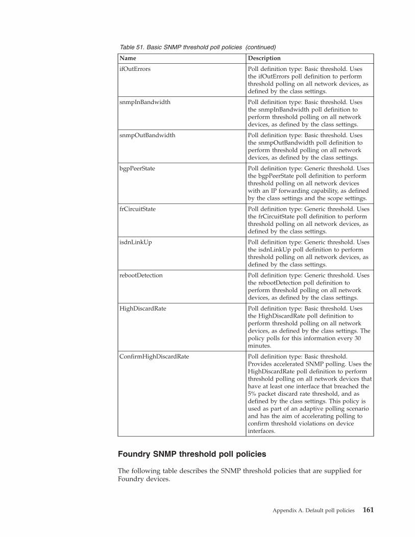
Table 51. Basic SNMP threshold poll policies (continued)
Name Description
ifOutErrors Poll definition type: Basic threshold. Usesthe ifOutErrors poll definition to performthreshold polling on all network devices, asdefined by the class settings.
snmpInBandwidth Poll definition type: Basic threshold. Usesthe snmpInBandwidth poll definition toperform threshold polling on all networkdevices, as defined by the class settings.
snmpOutBandwidth Poll definition type: Basic threshold. Usesthe snmpOutBandwidth poll definition toperform threshold polling on all networkdevices, as defined by the class settings.
bgpPeerState Poll definition type: Generic threshold. Usesthe bgpPeerState poll definition to performthreshold polling on all network deviceswith an IP forwarding capability, as definedby the class settings and the scope settings.
frCircuitState Poll definition type: Generic threshold. Usesthe frCircuitState poll definition to performthreshold polling on all network devices, asdefined by the class settings.
isdnLinkUp Poll definition type: Generic threshold. Usesthe isdnLinkUp poll definition to performthreshold polling on all network devices, asdefined by the class settings.
rebootDetection Poll definition type: Generic threshold. Usesthe rebootDetection poll definition toperform threshold polling on all networkdevices, as defined by the class settings.
HighDiscardRate Poll definition type: Basic threshold. Usesthe HighDiscardRate poll definition toperform threshold polling on all networkdevices, as defined by the class settings. Thepolicy polls for this information every 30minutes.
ConfirmHighDiscardRate Poll definition type: Basic threshold.Provides accelerated SNMP polling. Uses theHighDiscardRate poll definition to performthreshold polling on all network devices thathave at least one interface that breached the5% packet discard rate threshold, and asdefined by the class settings. This policy isused as part of an adaptive polling scenarioand has the aim of accelerating polling toconfirm threshold violations on deviceinterfaces.
Foundry SNMP threshold poll policies
The following table describes the SNMP threshold policies that are supplied forFoundry devices.
Appendix A. Default poll policies 161
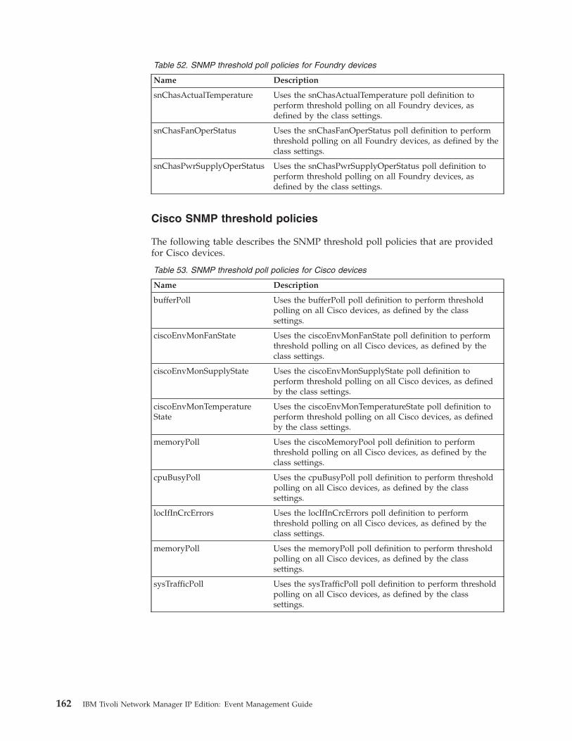
Table 52. SNMP threshold poll policies for Foundry devices
Name Description
snChasActualTemperature Uses the snChasActualTemperature poll definition toperform threshold polling on all Foundry devices, asdefined by the class settings.
snChasFanOperStatus Uses the snChasFanOperStatus poll definition to performthreshold polling on all Foundry devices, as defined by theclass settings.
snChasPwrSupplyOperStatus Uses the snChasPwrSupplyOperStatus poll definition toperform threshold polling on all Foundry devices, asdefined by the class settings.
Cisco SNMP threshold policies
The following table describes the SNMP threshold poll policies that are providedfor Cisco devices.
Table 53. SNMP threshold poll policies for Cisco devices
Name Description
bufferPoll Uses the bufferPoll poll definition to perform thresholdpolling on all Cisco devices, as defined by the classsettings.
ciscoEnvMonFanState Uses the ciscoEnvMonFanState poll definition to performthreshold polling on all Cisco devices, as defined by theclass settings.
ciscoEnvMonSupplyState Uses the ciscoEnvMonSupplyState poll definition toperform threshold polling on all Cisco devices, as definedby the class settings.
ciscoEnvMonTemperatureState
Uses the ciscoEnvMonTemperatureState poll definition toperform threshold polling on all Cisco devices, as definedby the class settings.
memoryPoll Uses the ciscoMemoryPool poll definition to performthreshold polling on all Cisco devices, as defined by theclass settings.
cpuBusyPoll Uses the cpuBusyPoll poll definition to perform thresholdpolling on all Cisco devices, as defined by the classsettings.
locIfInCrcErrors Uses the locIfInCrcErrors poll definition to performthreshold polling on all Cisco devices, as defined by theclass settings.
memoryPoll Uses the memoryPoll poll definition to perform thresholdpolling on all Cisco devices, as defined by the classsettings.
sysTrafficPoll Uses the sysTrafficPoll poll definition to perform thresholdpolling on all Cisco devices, as defined by the classsettings.
162 IBM Tivoli Network Manager IP Edition: Event Management Guide
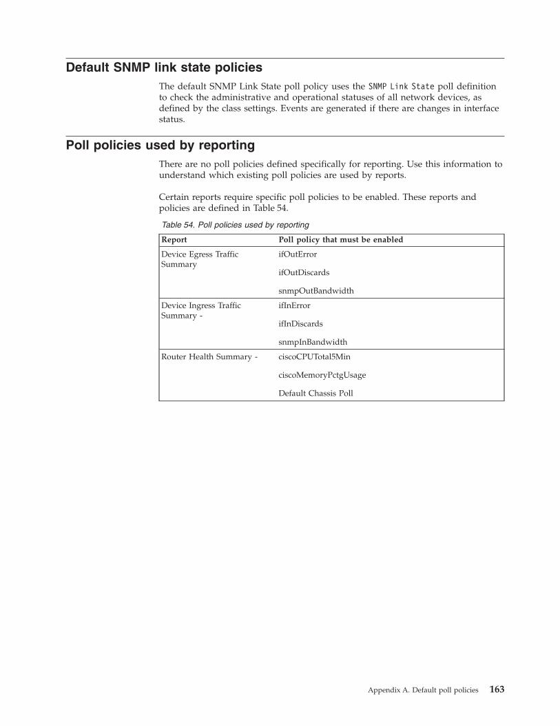
Default SNMP link state policiesThe default SNMP Link State poll policy uses the SNMP Link State poll definitionto check the administrative and operational statuses of all network devices, asdefined by the class settings. Events are generated if there are changes in interfacestatus.
Poll policies used by reportingThere are no poll policies defined specifically for reporting. Use this information tounderstand which existing poll policies are used by reports.
Certain reports require specific poll policies to be enabled. These reports andpolicies are defined in Table 54.
Table 54. Poll policies used by reporting
Report Poll policy that must be enabled
Device Egress TrafficSummary
ifOutError
ifOutDiscards
snmpOutBandwidth
Device Ingress TrafficSummary -
ifInError
ifInDiscards
snmpInBandwidth
Router Health Summary - ciscoCPUTotal5Min
ciscoMemoryPctgUsage
Default Chassis Poll
Appendix A. Default poll policies 163

164 IBM Tivoli Network Manager IP Edition: Event Management Guide
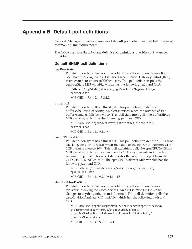
Appendix B. Default poll definitions
Network Manager provides a number of default poll definitions that fulfil the mostcommon polling requirements.
The following table describes the default poll definitions that Network Managerprovides.
Default SNMP poll definitions
bgpPeerStatePoll definition type: Generic threshold. This poll definition defines BGPpeer-state checking. An alert is raised when Border Gateway Patrol (BGP)peers change to an unestablished state. This poll definition polls thebgpPeerState MIB variable, which has the following path and OID:
Path: iso/org/dod/mgmt/mib-2/bgpPeerTable/bgpPeerEntry/bgpPeerState
MIB OID: 1.3.6.1.2.1.15.3.1.2
bufferPollPoll definition type: Basic threshold. This poll definition definesbuffer-exhaustion checking. An alert is raised when the number of freebuffer elements falls below 100. This poll definition polls the bufferElFreeMIB variable, which has the following path and OID:
MIB path: iso/org/dod/private/enterprises/cisco/local/bufferElFree
MIB OID: 1.3.6.1.4.1.9.2.1.9
ciscoCPUTotal5minPoll definition type: Basic threshold. This poll definition defines CPU usagechecking. An alert is raised when the value of the cpmCPUTotal5min CiscoMIB variable exceeds 80%. This poll definition polls the cpmCPUTotal5minMIB variable, which shows the overall CPU busy percentage in the lastfive-minute period. This object deprecates the avgBusy5 object from theOLD-CISCO-SYSTEM-MIB. The cpmCPUTotal5min MIB variable has thefollowing path and OID:
MIB path: iso/org/dod/private/enterprises/cisco/local/cpmCPUTotal5min
MIB OID: 1.3.6.1.4.1.9.9.109.1.1.1.1.5
ciscoEnvMonFanStatePoll definition type: Generic threshold. This poll definition definesfan-status checking for Cisco devices. An alert is raised if the statuschanges to anything other than 1 (normal). This poll definition polls theciscoEnvMonFanState MIB variable, which has the following path andOID:
MIB Path: iso/org/dod/mgmt/mib-2/private/enterprises/cisco/ciscoMgmt/ciscoEnvMonMIB/ciscoEnvMonObjects/ciscoEnvMonFanStatusTable/ciscoEnvMonFanStatusEntry/ciscoEnvMonFanState
MIB OID: 1.3.6.1.4.1.9.9.13.1.4.1.3
© Copyright IBM Corp. 2006, 2013 165
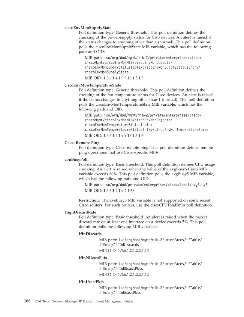
ciscoEnvMonSupplyStatePoll definition type: Generic threshold. This poll definition defines thechecking of the power-supply status for Ciso devices. An alert is raised ifthe status changes to anything other than 1 (normal). This poll definitionpolls the ciscoEnvMonSupplyState MIB variable, which has the followingpath and OID:
MIB path: iso/org/dod/mgmt/mib-2/private/enterprises/cisco/ciscoMgmt/ciscoEnvMonMIB/ciscoEnvMonObjects/ciscoEnvMonSupplyStatusTable/ciscoEnvMonSupplyStatusEntry/ciscoEnvMonSupplyState
MIB OID: 1.3.6.1.4.1.9.9.13.1.5.1.3
ciscoEnvMonTemperatureStatePoll definition type: Generic threshold. This poll definition defines thechecking of the fan-temperature status for Cisco devices. An alert is raisedif the status changes to anything other than 1 (normal). This poll definitionpolls the ciscoEnvMonTemperatureState MIB variable, which has thefollowing path and OID:
MIB path: iso/org/dod/mgmt/mib-2/private/enterprises/cisco/ciscoMgmt/ciscoEnvMonMIB/ciscoEnvMonObjects/ciscoEnvMonTemperatureStatusTable/ciscoEnvMonTemperateureStatusEntry/ciscoEnvMonTemperatureState
MIB OID: 1.3.6.1.4.1.9.9.13.1.3.1.6
Cisco Remote PingPoll definition type: Cisco remote ping. This poll definition defines remoteping operations that use Cisco-specific MIBs.
cpuBusyPollPoll definition type: Basic threshold. This poll definition defines CPU usagechecking. An alert is raised when the value of the avgBusy5 Cisco MIBvariable exceeds 80%. This poll definition polls the avgBusy5 MIB variable,which has the following path and OID:
MIB path: iso/org/dod/private/enterprises/cisco/local/avgBusy5MIB OID: 1.3.6.1.4.1.9.2.1.58
Restriction: The aveBusy5 MIB variable is not supported on some recentCisco routers. For such routers, use the ciscoCPUTotal5min poll definition.
HighDiscardRatePoll definition type: Basic threshold. An alert is raised when the packetdiscard rate on at least one interface on a device exceeds 5%. This polldefinition polls the following MIB variables:
ifInDiscards
MIB path: iso/org/dod/mgmt/mib-2/interfaces/ifTable/ifEntry/ifInDiscards
MIB OID: 1.3.6.1.2.1.2.2.1.13
ifInNUcastPkts
MIB path: iso/org/dod/mgmt/mib-2/interfaces/ifTable/ifEntry/ifInNUcastPkts
MIB OID: 1.3.6.1.2.1.2.2.1.12
ifInUcastPkts
MIB path: iso/org/dod/mgmt/mib-2/interfaces/ifTable/ifEntry/ifInUcastPkts
166 IBM Tivoli Network Manager IP Edition: Event Management Guide
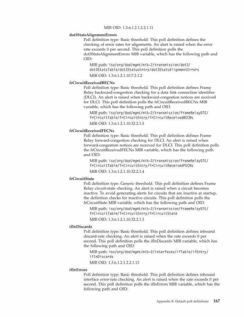
MIB OID: 1.3.6.1.2.1.2.2.1.11
dot3StatsAlignmentErrorsPoll definition type: Basic threshold. This poll definition defines thechecking of error rates for alignments. An alert is raised when the errorrate exceeds 0 per second. This poll definition polls thedot3StatsAlignmentErrors MIB variable, which has the following path andOID:
MIB path: iso/org/dod/mgmt/mib-2/transmission/dot3/dot3StatsTable/dot3StatusEntry/dot3StatsAlignmentErrors
MIB OID: 1.3.6.1.2.1.10.7.2.1.2
frCircuitReceivedBECNsPoll definition type: Basic threshold. This poll definition defines FrameRelay backward-congestion checking for a data link connection identifier(DLCI). An alert is raised when backward-congestion notices are receivedfor DLCI. This poll definition polls the frCircuitReceivedBECNs MIBvariable, which has the following path and OID:
MIB path: iso/org/dod/mgmt/mib-2/transmission/frameRelayDTE/frCircuitTable/frCircuitEntry/frCircuitReceivedBECNs
MIB OID: 1.3.6.1.2.1.10.32.2.1.5
frCircuitReceivedFECNsPoll definition type: Basic threshold. This poll definition defines FrameRelay forward-congestion checking for DLCI. An alert is raised whenforward-congestion notices are received for DLCI. This poll definition pollsthe frCircuitReceivedFECNs MIB variable, which has the following pathand OID:
MIB path: iso/org/dod/mgmt/mib-2/transmission/frameRelayDTE/frCircuitTable/frCircuitEntry/frCircuitReceivedFECNs
MIB OID: 1.3.6.1.2.1.10.32.2.1.4
frCircuitStatePoll definition type: Generic threshold. This poll definition defines FrameRelay circuit-state checking. An alert is raised when a circuit becomesinactive. To avoid generating alerts for circuits that are inactive at startup,the definition checks for inactive circuits. This poll definition polls thefrCircuitState MIB variable, which has the following path and OID:
MIB path: iso/org/dod/mgmt/mib-2/transmission/frameRelayDTE/frCircuitTable/frCircuitEntry/frCircuitState
MIB OID: 1.3.6.1.2.1.10.32.2.1.3
ifInDiscardsPoll definition type: Basic threshold. This poll definition defines inbounddiscard-rate checking. An alert is raised when the rate exceeds 0 persecond. This poll definition polls the ifInDiscards MIB variable, which hasthe following path and OID:
MIB path: iso/org/dod/mgmt/mib-2/interfaces/ifTable/ifEntry/ifInDiscards
MIB OID: 1.3.6.1.2.1.2.2.1.13
ifInErrorsPoll definition type: Basic threshold. This poll definition defines inboundinterface error-rate checking. An alert is raised when the rate exceeds 0 persecond. This poll definition polls the ifInErrors MIB variable, which has thefollowing path and OID:
Appendix B. Default poll definitions 167
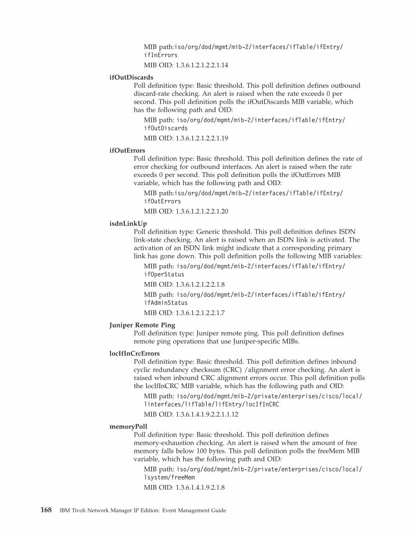
MIB path:iso/org/dod/mgmt/mib-2/interfaces/ifTable/ifEntry/ifInErrors
MIB OID: 1.3.6.1.2.1.2.2.1.14
ifOutDiscardsPoll definition type: Basic threshold. This poll definition defines outbounddiscard-rate checking. An alert is raised when the rate exceeds 0 persecond. This poll definition polls the ifOutDiscards MIB variable, whichhas the following path and OID:
MIB path: iso/org/dod/mgmt/mib-2/interfaces/ifTable/ifEntry/ifOutDiscards
MIB OID: 1.3.6.1.2.1.2.2.1.19
ifOutErrorsPoll definition type: Basic threshold. This poll definition defines the rate oferror checking for outbound interfaces. An alert is raised when the rateexceeds 0 per second. This poll definition polls the ifOutErrors MIBvariable, which has the following path and OID:
MIB path:iso/org/dod/mgmt/mib-2/interfaces/ifTable/ifEntry/ifOutErrors
MIB OID: 1.3.6.1.2.1.2.2.1.20
isdnLinkUpPoll definition type: Generic threshold. This poll definition defines ISDNlink-state checking. An alert is raised when an ISDN link is activated. Theactivation of an ISDN link might indicate that a corresponding primarylink has gone down. This poll definition polls the following MIB variables:
MIB path: iso/org/dod/mgmt/mib-2/interfaces/ifTable/ifEntry/ifOperStatus
MIB OID: 1.3.6.1.2.1.2.2.1.8MIB path: iso/org/dod/mgmt/mib-2/interfaces/ifTable/ifEntry/ifAdminStatus
MIB OID: 1.3.6.1.2.1.2.2.1.7
Juniper Remote PingPoll definition type: Juniper remote ping. This poll definition definesremote ping operations that use Juniper-specific MIBs.
locIfInCrcErrorsPoll definition type: Basic threshold. This poll definition defines inboundcyclic redundancy checksum (CRC) /alignment error checking. An alert israised when inbound CRC alignment errors occur. This poll definition pollsthe locIfInCRC MIB variable, which has the following path and OID:
MIB path: iso/org/dod/mgmt/mib-2/private/enterprises/cisco/local/linterfaces/lifTable/lifEntry/locIfInCRC
MIB OID: 1.3.6.1.4.1.9.2.2.1.1.12
memoryPollPoll definition type: Basic threshold. This poll definition definesmemory-exhaustion checking. An alert is raised when the amount of freememory falls below 100 bytes. This poll definition polls the freeMem MIBvariable, which has the following path and OID:
MIB path: iso/org/dod/mgmt/mib-2/private/enterprises/cisco/local/lsystem/freeMem
MIB OID: 1.3.6.1.4.1.9.2.1.8
168 IBM Tivoli Network Manager IP Edition: Event Management Guide
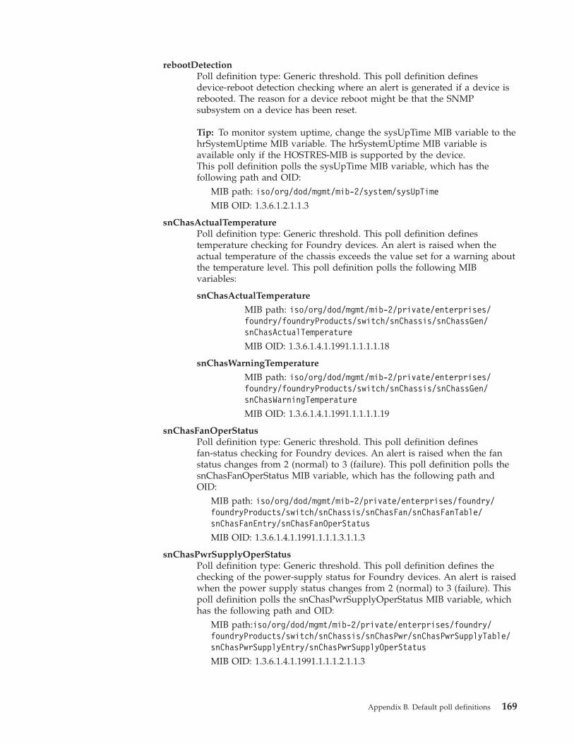
rebootDetectionPoll definition type: Generic threshold. This poll definition definesdevice-reboot detection checking where an alert is generated if a device isrebooted. The reason for a device reboot might be that the SNMPsubsystem on a device has been reset.
Tip: To monitor system uptime, change the sysUpTime MIB variable to thehrSystemUptime MIB variable. The hrSystemUptime MIB variable isavailable only if the HOSTRES-MIB is supported by the device.This poll definition polls the sysUpTime MIB variable, which has thefollowing path and OID:
MIB path: iso/org/dod/mgmt/mib-2/system/sysUpTimeMIB OID: 1.3.6.1.2.1.1.3
snChasActualTemperaturePoll definition type: Generic threshold. This poll definition definestemperature checking for Foundry devices. An alert is raised when theactual temperature of the chassis exceeds the value set for a warning aboutthe temperature level. This poll definition polls the following MIBvariables:
snChasActualTemperature
MIB path: iso/org/dod/mgmt/mib-2/private/enterprises/foundry/foundryProducts/switch/snChassis/snChassGen/snChasActualTemperature
MIB OID: 1.3.6.1.4.1.1991.1.1.1.1.18
snChasWarningTemperature
MIB path: iso/org/dod/mgmt/mib-2/private/enterprises/foundry/foundryProducts/switch/snChassis/snChassGen/snChasWarningTemperature
MIB OID: 1.3.6.1.4.1.1991.1.1.1.1.19
snChasFanOperStatusPoll definition type: Generic threshold. This poll definition definesfan-status checking for Foundry devices. An alert is raised when the fanstatus changes from 2 (normal) to 3 (failure). This poll definition polls thesnChasFanOperStatus MIB variable, which has the following path andOID:
MIB path: iso/org/dod/mgmt/mib-2/private/enterprises/foundry/foundryProducts/switch/snChassis/snChasFan/snChasFanTable/snChasFanEntry/snChasFanOperStatus
MIB OID: 1.3.6.1.4.1.1991.1.1.1.3.1.1.3
snChasPwrSupplyOperStatusPoll definition type: Generic threshold. This poll definition defines thechecking of the power-supply status for Foundry devices. An alert is raisedwhen the power supply status changes from 2 (normal) to 3 (failure). Thispoll definition polls the snChasPwrSupplyOperStatus MIB variable, whichhas the following path and OID:
MIB path:iso/org/dod/mgmt/mib-2/private/enterprises/foundry/foundryProducts/switch/snChassis/snChasPwr/snChasPwrSupplyTable/snChasPwrSupplyEntry/snChasPwrSupplyOperStatus
MIB OID: 1.3.6.1.4.1.1991.1.1.1.2.1.1.3
Appendix B. Default poll definitions 169
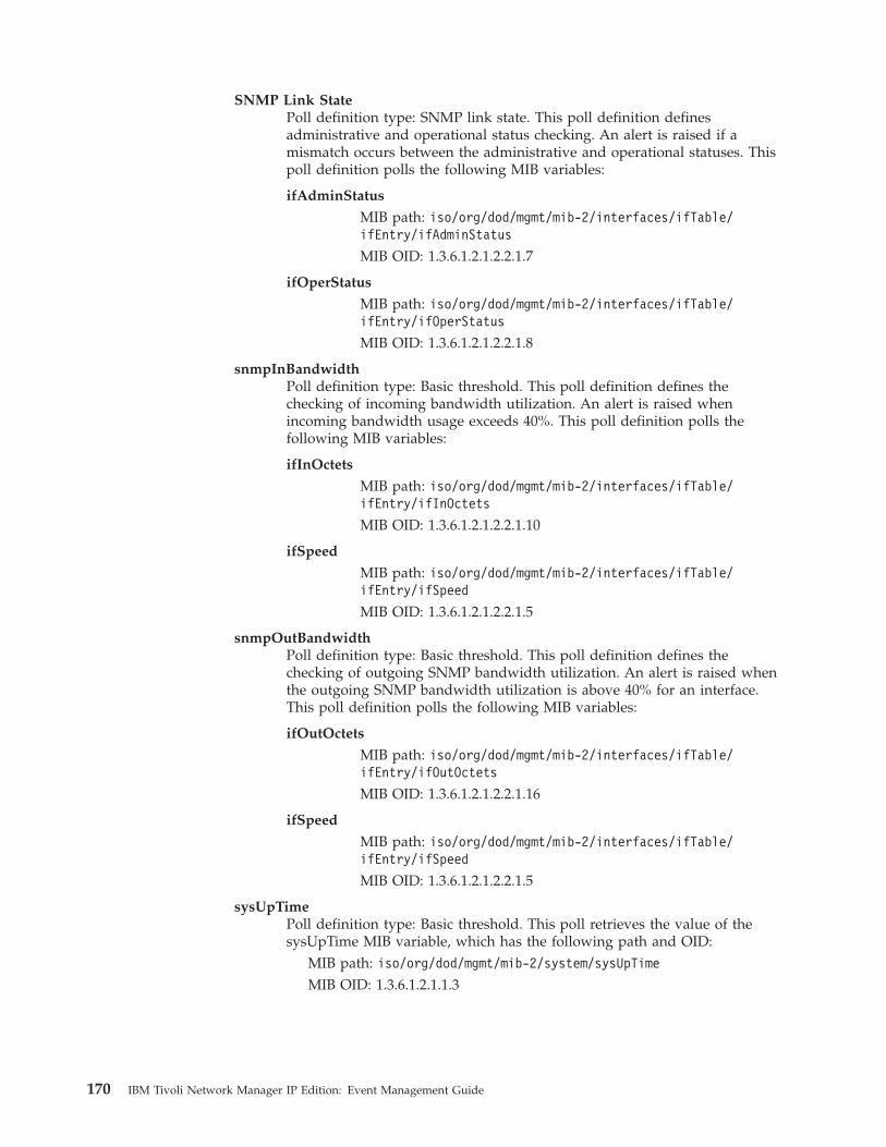
SNMP Link StatePoll definition type: SNMP link state. This poll definition definesadministrative and operational status checking. An alert is raised if amismatch occurs between the administrative and operational statuses. Thispoll definition polls the following MIB variables:
ifAdminStatus
MIB path: iso/org/dod/mgmt/mib-2/interfaces/ifTable/ifEntry/ifAdminStatus
MIB OID: 1.3.6.1.2.1.2.2.1.7
ifOperStatus
MIB path: iso/org/dod/mgmt/mib-2/interfaces/ifTable/ifEntry/ifOperStatus
MIB OID: 1.3.6.1.2.1.2.2.1.8
snmpInBandwidthPoll definition type: Basic threshold. This poll definition defines thechecking of incoming bandwidth utilization. An alert is raised whenincoming bandwidth usage exceeds 40%. This poll definition polls thefollowing MIB variables:
ifInOctets
MIB path: iso/org/dod/mgmt/mib-2/interfaces/ifTable/ifEntry/ifInOctets
MIB OID: 1.3.6.1.2.1.2.2.1.10
ifSpeed
MIB path: iso/org/dod/mgmt/mib-2/interfaces/ifTable/ifEntry/ifSpeed
MIB OID: 1.3.6.1.2.1.2.2.1.5
snmpOutBandwidthPoll definition type: Basic threshold. This poll definition defines thechecking of outgoing SNMP bandwidth utilization. An alert is raised whenthe outgoing SNMP bandwidth utilization is above 40% for an interface.This poll definition polls the following MIB variables:
ifOutOctets
MIB path: iso/org/dod/mgmt/mib-2/interfaces/ifTable/ifEntry/ifOutOctets
MIB OID: 1.3.6.1.2.1.2.2.1.16
ifSpeed
MIB path: iso/org/dod/mgmt/mib-2/interfaces/ifTable/ifEntry/ifSpeed
MIB OID: 1.3.6.1.2.1.2.2.1.5
sysUpTimePoll definition type: Basic threshold. This poll retrieves the value of thesysUpTime MIB variable, which has the following path and OID:
MIB path: iso/org/dod/mgmt/mib-2/system/sysUpTimeMIB OID: 1.3.6.1.2.1.1.3
170 IBM Tivoli Network Manager IP Edition: Event Management Guide
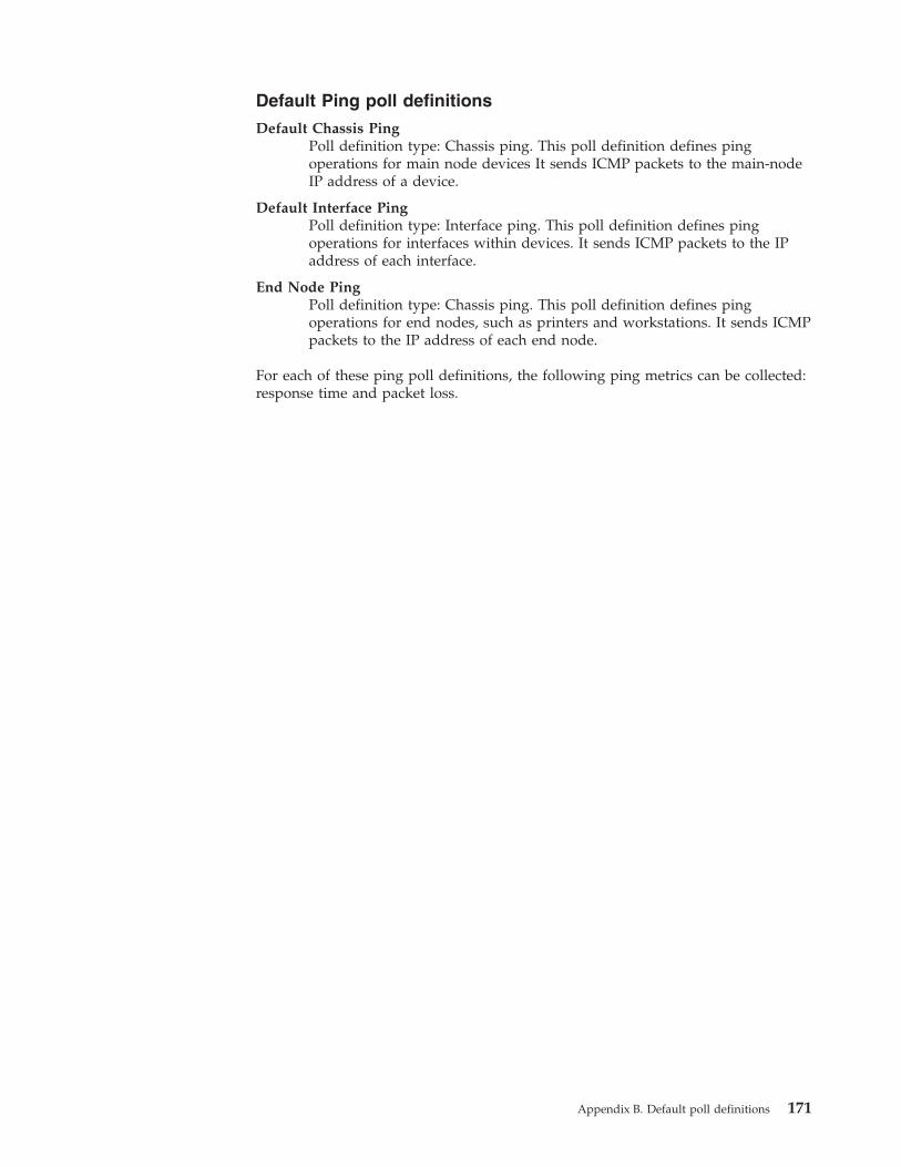
Default Ping poll definitions
Default Chassis PingPoll definition type: Chassis ping. This poll definition defines pingoperations for main node devices It sends ICMP packets to the main-nodeIP address of a device.
Default Interface PingPoll definition type: Interface ping. This poll definition defines pingoperations for interfaces within devices. It sends ICMP packets to the IPaddress of each interface.
End Node PingPoll definition type: Chassis ping. This poll definition defines pingoperations for end nodes, such as printers and workstations. It sends ICMPpackets to the IP address of each end node.
For each of these ping poll definitions, the following ping metrics can be collected:response time and packet loss.
Appendix B. Default poll definitions 171

172 IBM Tivoli Network Manager IP Edition: Event Management Guide
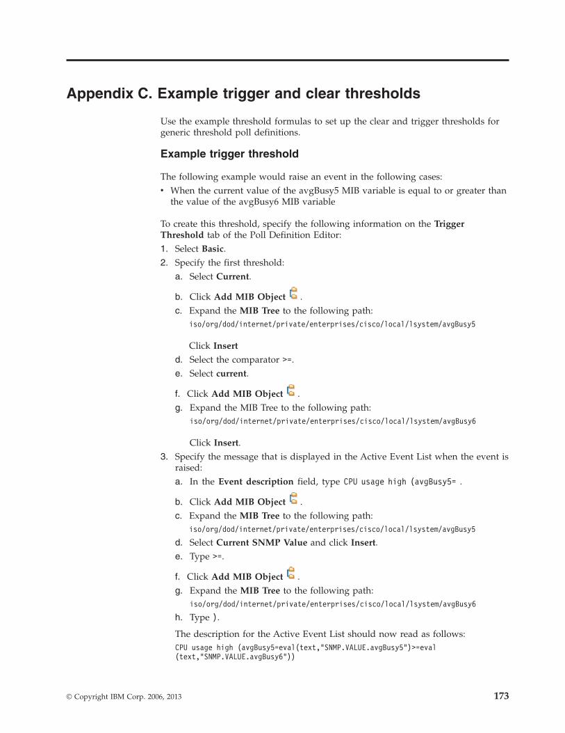
Appendix C. Example trigger and clear thresholds
Use the example threshold formulas to set up the clear and trigger thresholds forgeneric threshold poll definitions.
Example trigger threshold
The following example would raise an event in the following cases:v When the current value of the avgBusy5 MIB variable is equal to or greater than
the value of the avgBusy6 MIB variable
To create this threshold, specify the following information on the TriggerThreshold tab of the Poll Definition Editor:1. Select Basic.2. Specify the first threshold:
a. Select Current.
b. Click Add MIB Object .c. Expand the MIB Tree to the following path:
iso/org/dod/internet/private/enterprises/cisco/local/lsystem/avgBusy5
Click Insert
d. Select the comparator >=.e. Select current.
f. Click Add MIB Object .g. Expand the MIB Tree to the following path:
iso/org/dod/internet/private/enterprises/cisco/local/lsystem/avgBusy6
Click Insert.3. Specify the message that is displayed in the Active Event List when the event is
raised:a. In the Event description field, type CPU usage high (avgBusy5= .
b. Click Add MIB Object .c. Expand the MIB Tree to the following path:
iso/org/dod/internet/private/enterprises/cisco/local/lsystem/avgBusy5
d. Select Current SNMP Value and click Insert.e. Type >=.
f. Click Add MIB Object .g. Expand the MIB Tree to the following path:
iso/org/dod/internet/private/enterprises/cisco/local/lsystem/avgBusy6
h. Type ).
The description for the Active Event List should now read as follows:CPU usage high (avgBusy5=eval(text,"SNMP.VALUE.avgBusy5")>=eval(text,"SNMP.VALUE.avgBusy6"))
© Copyright IBM Corp. 2006, 2013 173
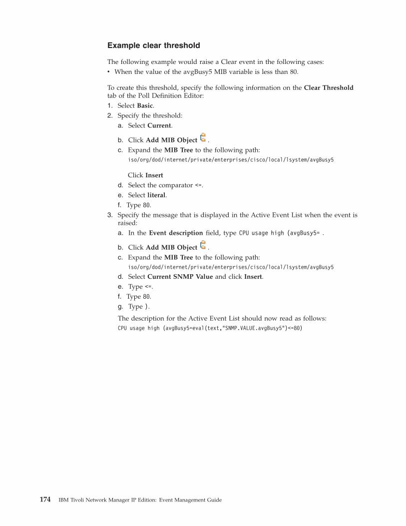
Example clear threshold
The following example would raise a Clear event in the following cases:v When the value of the avgBusy5 MIB variable is less than 80.
To create this threshold, specify the following information on the Clear Thresholdtab of the Poll Definition Editor:1. Select Basic.2. Specify the threshold:
a. Select Current.
b. Click Add MIB Object .c. Expand the MIB Tree to the following path:
iso/org/dod/internet/private/enterprises/cisco/local/lsystem/avgBusy5
Click Insert
d. Select the comparator <=.e. Select literal.f. Type 80.
3. Specify the message that is displayed in the Active Event List when the event israised:a. In the Event description field, type CPU usage high (avgBusy5= .
b. Click Add MIB Object .c. Expand the MIB Tree to the following path:
iso/org/dod/internet/private/enterprises/cisco/local/lsystem/avgBusy5
d. Select Current SNMP Value and click Insert.e. Type <=.f. Type 80.g. Type ).
The description for the Active Event List should now read as follows:CPU usage high (avgBusy5=eval(text,"SNMP.VALUE.avgBusy5")<=80)
174 IBM Tivoli Network Manager IP Edition: Event Management Guide
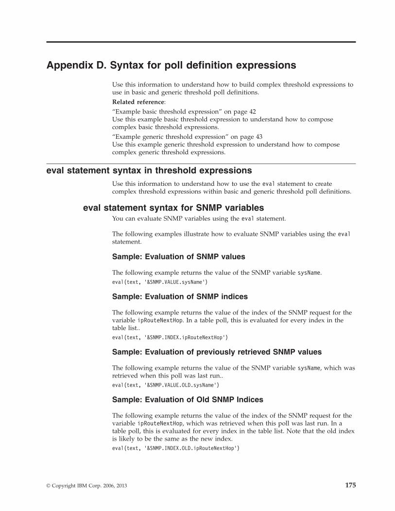
Appendix D. Syntax for poll definition expressions
Use this information to understand how to build complex threshold expressions touse in basic and generic threshold poll definitions.Related reference:“Example basic threshold expression” on page 42Use this example basic threshold expression to understand how to composecomplex basic threshold expressions.“Example generic threshold expression” on page 43Use this example generic threshold expression to understand how to composecomplex generic threshold expressions.
eval statement syntax in threshold expressionsUse this information to understand how to use the eval statement to createcomplex threshold expressions within basic and generic threshold poll definitions.
eval statement syntax for SNMP variablesYou can evaluate SNMP variables using the eval statement.
The following examples illustrate how to evaluate SNMP variables using the evalstatement.
Sample: Evaluation of SNMP values
The following example returns the value of the SNMP variable sysName.eval(text, ’&SNMP.VALUE.sysName’)
Sample: Evaluation of SNMP indices
The following example returns the value of the index of the SNMP request for thevariable ipRouteNextHop. In a table poll, this is evaluated for every index in thetable list..eval(text, ’&SNMP.INDEX.ipRouteNextHop’)
Sample: Evaluation of previously retrieved SNMP values
The following example returns the value of the SNMP variable sysName, which wasretrieved when this poll was last run..eval(text, ’&SNMP.VALUE.OLD.sysName’)
Sample: Evaluation of Old SNMP Indices
The following example returns the value of the index of the SNMP request for thevariable ipRouteNextHop, which was retrieved when this poll was last run. In atable poll, this is evaluated for every index in the table list. Note that the old indexis likely to be the same as the new index.eval(text, ’&SNMP.INDEX.OLD.ipRouteNextHop’)
© Copyright IBM Corp. 2006, 2013 175
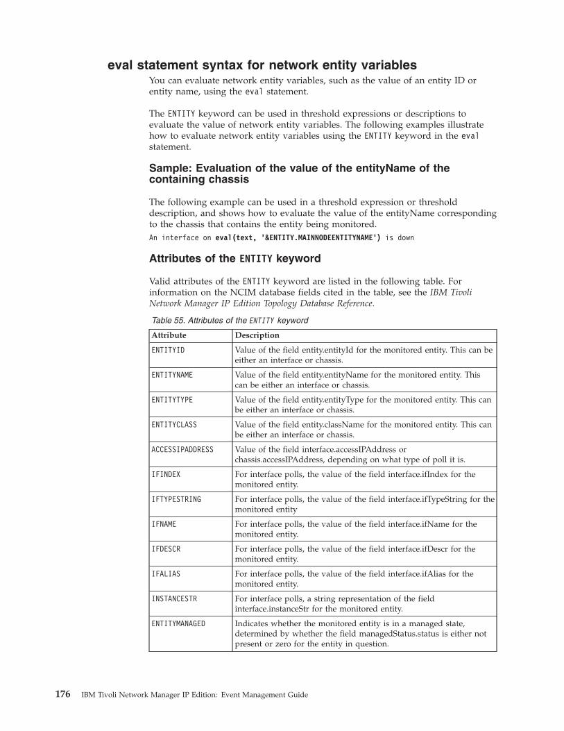
eval statement syntax for network entity variablesYou can evaluate network entity variables, such as the value of an entity ID orentity name, using the eval statement.
The ENTITY keyword can be used in threshold expressions or descriptions toevaluate the value of network entity variables. The following examples illustratehow to evaluate network entity variables using the ENTITY keyword in the evalstatement.
Sample: Evaluation of the value of the entityName of thecontaining chassis
The following example can be used in a threshold expression or thresholddescription, and shows how to evaluate the value of the entityName correspondingto the chassis that contains the entity being monitored.An interface on eval(text, ’&ENTITY.MAINNODEENTITYNAME’) is down
Attributes of the ENTITY keyword
Valid attributes of the ENTITY keyword are listed in the following table. Forinformation on the NCIM database fields cited in the table, see the IBM TivoliNetwork Manager IP Edition Topology Database Reference.
Table 55. Attributes of the ENTITY keyword
Attribute Description
ENTITYID Value of the field entity.entityId for the monitored entity. This can beeither an interface or chassis.
ENTITYNAME Value of the field entity.entityName for the monitored entity. Thiscan be either an interface or chassis.
ENTITYTYPE Value of the field entity.entityType for the monitored entity. This canbe either an interface or chassis.
ENTITYCLASS Value of the field entity.className for the monitored entity. This canbe either an interface or chassis.
ACCESSIPADDRESS Value of the field interface.accessIPAddress orchassis.accessIPAddress, depending on what type of poll it is.
IFINDEX For interface polls, the value of the field interface.ifIndex for themonitored entity.
IFTYPESTRING For interface polls, the value of the field interface.ifTypeString for themonitored entity
IFNAME For interface polls, the value of the field interface.ifName for themonitored entity.
IFDESCR For interface polls, the value of the field interface.ifDescr for themonitored entity.
IFALIAS For interface polls, the value of the field interface.ifAlias for themonitored entity.
INSTANCESTR For interface polls, a string representation of the fieldinterface.instanceStr for the monitored entity.
ENTITYMANAGED Indicates whether the monitored entity is in a managed state,determined by whether the field managedStatus.status is either notpresent or zero for the entity in question.
176 IBM Tivoli Network Manager IP Edition: Event Management Guide
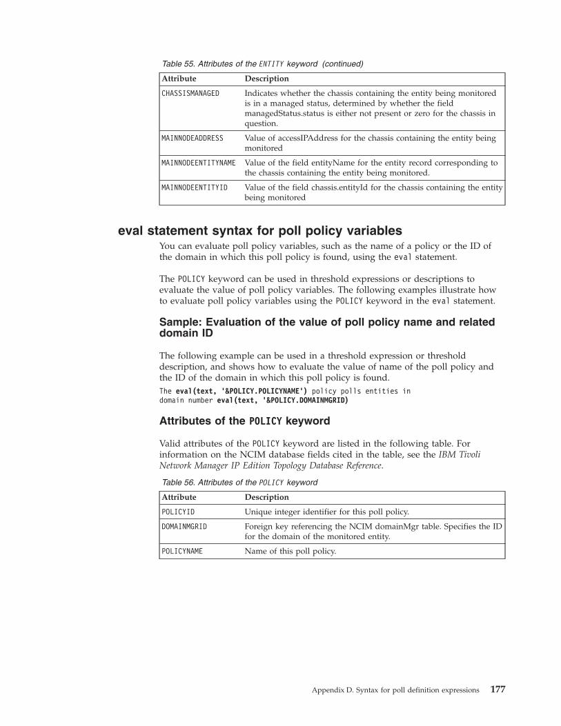
Table 55. Attributes of the ENTITY keyword (continued)
Attribute Description
CHASSISMANAGED Indicates whether the chassis containing the entity being monitoredis in a managed status, determined by whether the fieldmanagedStatus.status is either not present or zero for the chassis inquestion.
MAINNODEADDRESS Value of accessIPAddress for the chassis containing the entity beingmonitored
MAINNODEENTITYNAME Value of the field entityName for the entity record corresponding tothe chassis containing the entity being monitored.
MAINNODEENTITYID Value of the field chassis.entityId for the chassis containing the entitybeing monitored
eval statement syntax for poll policy variablesYou can evaluate poll policy variables, such as the name of a policy or the ID ofthe domain in which this poll policy is found, using the eval statement.
The POLICY keyword can be used in threshold expressions or descriptions toevaluate the value of poll policy variables. The following examples illustrate howto evaluate poll policy variables using the POLICY keyword in the eval statement.
Sample: Evaluation of the value of poll policy name and relateddomain ID
The following example can be used in a threshold expression or thresholddescription, and shows how to evaluate the value of name of the poll policy andthe ID of the domain in which this poll policy is found.The eval(text, ’&POLICY.POLICYNAME’) policy polls entities indomain number eval(text, ’&POLICY.DOMAINMGRID)
Attributes of the POLICY keyword
Valid attributes of the POLICY keyword are listed in the following table. Forinformation on the NCIM database fields cited in the table, see the IBM TivoliNetwork Manager IP Edition Topology Database Reference.
Table 56. Attributes of the POLICY keyword
Attribute Description
POLICYID Unique integer identifier for this poll policy.
DOMAINMGRID Foreign key referencing the NCIM domainMgr table. Specifies the IDfor the domain of the monitored entity.
POLICYNAME Name of this poll policy.
Appendix D. Syntax for poll definition expressions 177
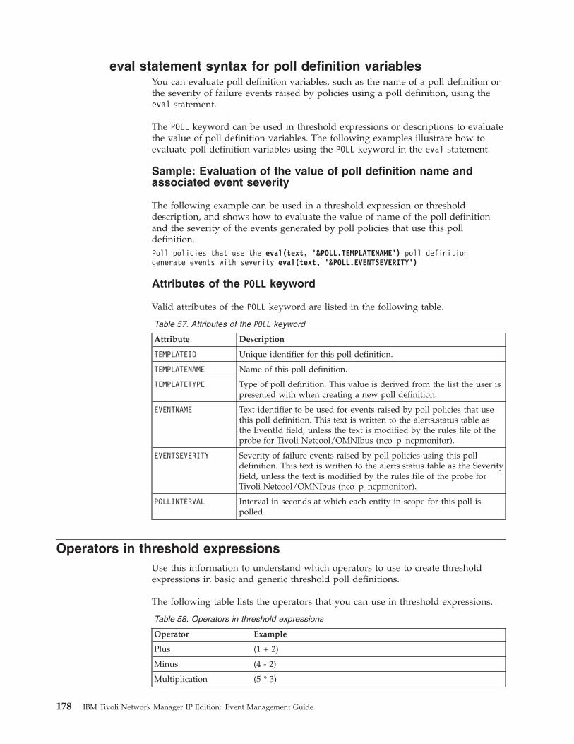
eval statement syntax for poll definition variablesYou can evaluate poll definition variables, such as the name of a poll definition orthe severity of failure events raised by policies using a poll definition, using theeval statement.
The POLL keyword can be used in threshold expressions or descriptions to evaluatethe value of poll definition variables. The following examples illustrate how toevaluate poll definition variables using the POLL keyword in the eval statement.
Sample: Evaluation of the value of poll definition name andassociated event severity
The following example can be used in a threshold expression or thresholddescription, and shows how to evaluate the value of name of the poll definitionand the severity of the events generated by poll policies that use this polldefinition.Poll policies that use the eval(text, ’&POLL.TEMPLATENAME’) poll definitiongenerate events with severity eval(text, ’&POLL.EVENTSEVERITY’)
Attributes of the POLL keyword
Valid attributes of the POLL keyword are listed in the following table.
Table 57. Attributes of the POLL keyword
Attribute Description
TEMPLATEID Unique identifier for this poll definition.
TEMPLATENAME Name of this poll definition.
TEMPLATETYPE Type of poll definition. This value is derived from the list the user ispresented with when creating a new poll definition.
EVENTNAME Text identifier to be used for events raised by poll policies that usethis poll definition. This text is written to the alerts.status table asthe EventId field, unless the text is modified by the rules file of theprobe for Tivoli Netcool/OMNIbus (nco_p_ncpmonitor).
EVENTSEVERITY Severity of failure events raised by poll policies using this polldefinition. This text is written to the alerts.status table as the Severityfield, unless the text is modified by the rules file of the probe forTivoli Netcool/OMNIbus (nco_p_ncpmonitor).
POLLINTERVAL Interval in seconds at which each entity in scope for this poll ispolled.
Operators in threshold expressionsUse this information to understand which operators to use to create thresholdexpressions in basic and generic threshold poll definitions.
The following table lists the operators that you can use in threshold expressions.
Table 58. Operators in threshold expressions
Operator Example
Plus (1 + 2)
Minus (4 - 2)
Multiplication (5 * 3)
178 IBM Tivoli Network Manager IP Edition: Event Management Guide
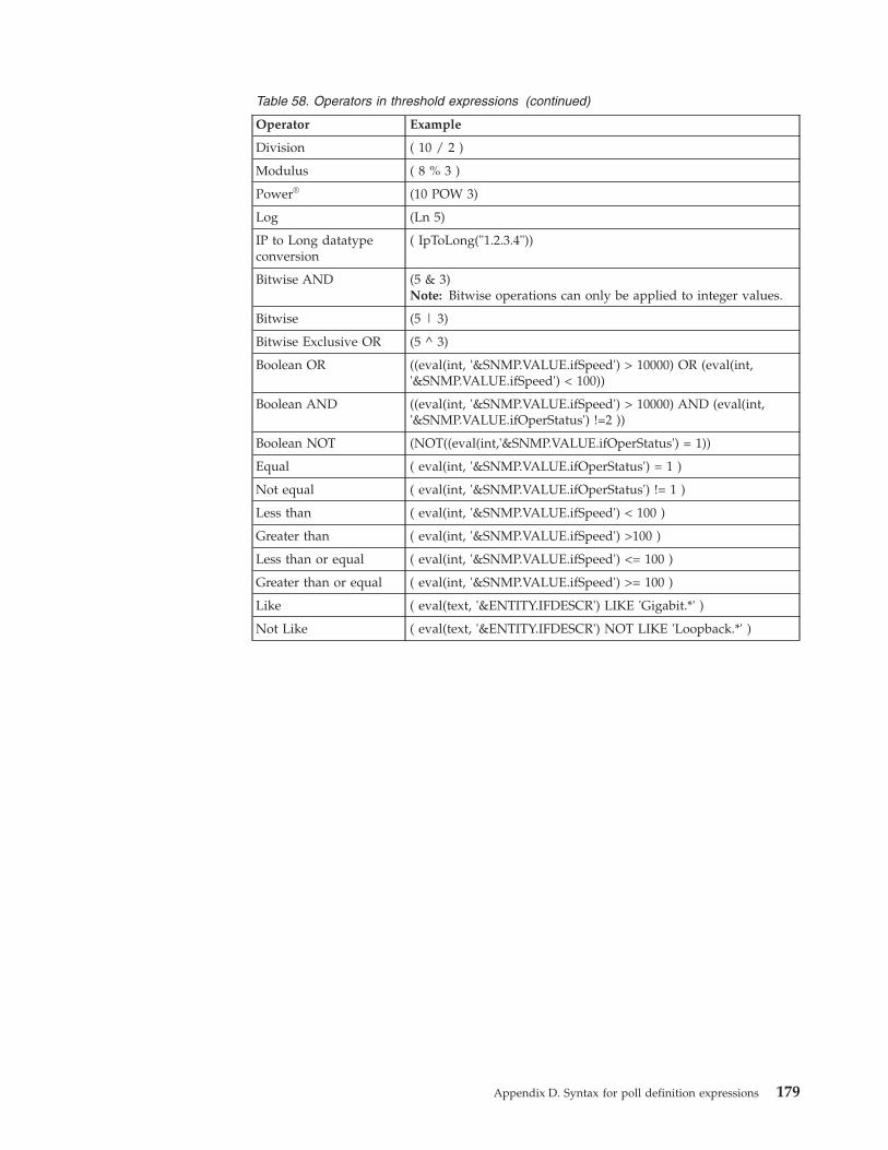
Table 58. Operators in threshold expressions (continued)
Operator Example
Division ( 10 / 2 )
Modulus ( 8 % 3 )
Power® (10 POW 3)
Log (Ln 5)
IP to Long datatypeconversion
( IpToLong("1.2.3.4"))
Bitwise AND (5 & 3)Note: Bitwise operations can only be applied to integer values.
Bitwise (5 | 3)
Bitwise Exclusive OR (5 ^ 3)
Boolean OR ((eval(int, '&SNMP.VALUE.ifSpeed') > 10000) OR (eval(int,'&SNMP.VALUE.ifSpeed') < 100))
Boolean AND ((eval(int, '&SNMP.VALUE.ifSpeed') > 10000) AND (eval(int,'&SNMP.VALUE.ifOperStatus') !=2 ))
Boolean NOT (NOT((eval(int,'&SNMP.VALUE.ifOperStatus') = 1))
Equal ( eval(int, '&SNMP.VALUE.ifOperStatus') = 1 )
Not equal ( eval(int, '&SNMP.VALUE.ifOperStatus') != 1 )
Less than ( eval(int, '&SNMP.VALUE.ifSpeed') < 100 )
Greater than ( eval(int, '&SNMP.VALUE.ifSpeed') >100 )
Less than or equal ( eval(int, '&SNMP.VALUE.ifSpeed') <= 100 )
Greater than or equal ( eval(int, '&SNMP.VALUE.ifSpeed') >= 100 )
Like ( eval(text, '&ENTITY.IFDESCR') LIKE 'Gigabit.*' )
Not Like ( eval(text, '&ENTITY.IFDESCR') NOT LIKE 'Loopback.*' )
Appendix D. Syntax for poll definition expressions 179

180 IBM Tivoli Network Manager IP Edition: Event Management Guide
Appendix E. Configuration of the Probe for TivoliNetcool/OMNIbus
The Probe for Tivoli Netcool/OMNIbus (nco_p_ncpmonitor) acquires and processesthe events that are generated by Network Manager polls and processes, andforwards these events to the ObjectServer.
The Probe for Tivoli Netcool/OMNIbus is installed in the $NCHOME/probes/archdirectory, where arch represents an operating system directory. You can configurethe probe by using its configuration files, which are as follows:v Properties file: nco_p_ncpmonitor.propsv Rules file: nco_p_ncpmonitor.rules
Note: The executable file (or nco_p_ncpmonitor command) for the probe is alsoinstalled in the $NCHOME/probes/arch directory. The probe is, however, configuredto run under the domain process controller CTRL, by default, and thenco_p_ncpmonitor command should be run manually only for troubleshootingpurposes.
The events raised in Network Manager are domain-specific. When NetworkManager runs in failover mode, the probe uses the virtual domain name bydefault, provided the name is configured in the $NCHOME/etc/precision/ConfigItnm.cfg file.
For more information about probe concepts, see the IBM Tivoli Netcool/OMNIbusProbe and Gateway Guide in the Tivoli Netcool/OMNIbus information centre athttp://publib.boulder.ibm.com/infocenter/tivihelp/v8r1/topic/com.ibm.tivoli.nam.doc/welcome_ob.htm.
About the nco_p_ncpmonitor.props fileThe $NCHOME/probes/arch/nco_p_ncpmonitor.props file defines the environment inwhich the Probe for Tivoli Netcool/OMNIbus runs.
The properties file is formed of name-value pairs that are separated by a colon.The default properties file lists a subset of the properties that the probe supports;these properties are commented out with a number sign (#) at the beginning of theline. The standard set of common probe properties, which are applicable for theversion of Tivoli Netcool/OMNIbus being run, can be specified for the Probe forTivoli Netcool/OMNIbus, where relevant.
A suggested practice for changing the default values of the properties is that youadd a name-value line for each required property at the bottom of the file. Tospecify a property, ensure that the line is uncommented and then modify the valueas required. String values must be enclosed in quotation marks; other values donot require quotation marks. For example:Server : "VIRTUAL"RulesFile : "$NCHOME/probes/solaris2/nco_p_ncpmonitor.rules"Buffering : 1BufferSize : 15
© Copyright IBM Corp. 2006, 2013 181
For troubleshooting purposes, you can alternatively configure probe propertiesfrom the command line by running the nco_p_ncpmonitor command with therelevant command-line options.
For information about the properties that are common to probes, see the IBM TivoliNetcool/OMNIbus Probe and Gateway Guide in the Tivoli Netcool/OMNIbusinformation centre at http://publib.boulder.ibm.com/infocenter/tivihelp/v8r1/topic/com.ibm.tivoli.nam.doc/welcome_ob.htm.
About the nco_p_ncpmonitor.rules fileThe $NCHOME/probes/arch/nco_p_ncpmonitor.rules file defines how the Probe forTivoli Netcool/OMNIbus should process Network Manager event data to create ameaningful Tivoli Netcool/OMNIbus event.
nco_p_ncpmonitor.rules configuration referenceThe rules file maps Network Manager event data to ObjectServer fields, and can beused to customize the behavior of the probe. Knowledge of the TivoliNetcool/OMNIbus probe rules syntax is required for rules file configuration.
The probe uses tokens and elements, and applies rules, to transform NetworkManager event source data into a format that the ObjectServer can recognize. Theraw event source data is converted to tokens, which are then parsed into elements.The rules file is used to perform conditional processing on the elements, and tomap them to ObjectServer alerts.status fields. In the rules file, elements areidentified by the $ symbol and alerts.status fields are identified by the @ symbol.The rules file configuration maps elements to fields, as shown in the followingsample code:@Summary=$Description
In this example, @Summary identifies the alerts.status field, and $Descriptionidentifies the Network Manager input field.
Where the Network Manager ExtraInfo field is used with nested fields to storeadditional data on entities (for example, ExtraInfo->ifIndex), these fields areavailable in the following format in the rules file:$ExtraInfo_variable
Where variable represents a Management Information Base (MIB) variable (forexample, ifIndex), or other data (for example, column names in NCIM tables). MIBvariables are specified in mixed case characters, and other data, in uppercasecharacters. For example:$ExtraInfo_ifIndex$ExtraInfo_MONITOREDENTITYID
To configure the rules file for the Probe for Tivoli Netcool/OMNIbus, it isnecessary to have an understanding of:v The Network Manager event source data that is available for use in the probe
rules filev The set of alerts.status fields that can be populated with event data from
Network Managerv The data mapping between the Network Manager and alerts.status fields
182 IBM Tivoli Network Manager IP Edition: Event Management Guide
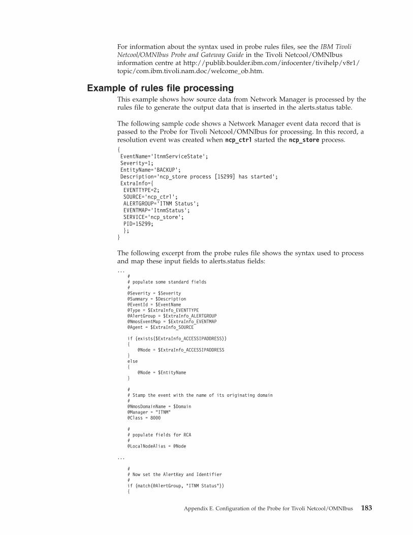
For information about the syntax used in probe rules files, see the IBM TivoliNetcool/OMNIbus Probe and Gateway Guide in the Tivoli Netcool/OMNIbusinformation centre at http://publib.boulder.ibm.com/infocenter/tivihelp/v8r1/topic/com.ibm.tivoli.nam.doc/welcome_ob.htm.
Example of rules file processingThis example shows how source data from Network Manager is processed by therules file to generate the output data that is inserted in the alerts.status table.
The following sample code shows a Network Manager event data record that ispassed to the Probe for Tivoli Netcool/OMNIbus for processing. In this record, aresolution event was created when ncp_ctrl started the ncp_store process.{EventName=’ItnmServiceState’;Severity=1;EntityName=’BACKUP’;Description=’ncp_store process [15299] has started’;ExtraInfo={EVENTTYPE=2;SOURCE=’ncp_ctrl’;ALERTGROUP=’ITNM Status’;EVENTMAP=’ItnmStatus’;SERVICE=’ncp_store’;PID=15299;};
}
The following excerpt from the probe rules file shows the syntax used to processand map these input fields to alerts.status fields:...
## populate some standard fields#@Severity = $Severity@Summary = $Description@EventId = $EventName@Type = $ExtraInfo_EVENTTYPE@AlertGroup = $ExtraInfo_ALERTGROUP@NmosEventMap = $ExtraInfo_EVENTMAP@Agent = $ExtraInfo_SOURCE
if (exists($ExtraInfo_ACCESSIPADDRESS)){
@Node = $ExtraInfo_ACCESSIPADDRESS}else{
@Node = $EntityName}
## Stamp the event with the name of its originating domain#@NmosDomainName = $Domain@Manager = "ITNM"@Class = 8000
## populate fields for RCA#@LocalNodeAlias = @Node
...
## Now set the AlertKey and Identifier#if (match(@AlertGroup, "ITNM Status")){
Appendix E. Configuration of the Probe for Tivoli Netcool/OMNIbus 183
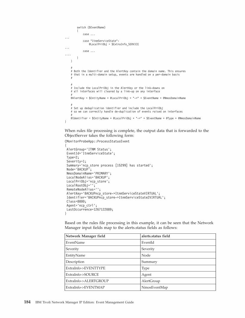
switch ($EventName){
case ......
case "ItnmServiceState":@LocalPriObj = $ExtraInfo_SERVICE
...case ...
....}
}
## Both the Identifier and the AlertKey contain the domain name. This ensures# that in a multi-domain setup, events are handled on a per-domain basis#
## Include the LocalPriObj in the AlertKey or the link-downs on# all interfaces will cleared by a link-up on any interface#@AlertKey = $EntityName + @LocalPriObj + "->" + $EventName + @NmosDomainName
## Set up deduplication identifier and include the LocalPriObj# so we can correctly handle de-duplication of events raised on interfaces#@Identifier = $EntityName + @LocalPriObj + "->" + $EventName + @Type + @NmosDomainName
}
When rules file processing is complete, the output data that is forwarded to theObjectServer takes the following form:CMonitorProbeApp::ProcessStatusEvent{AlertGroup=’ITNM Status’;EventId=’ItnmServiceState’;Type=2;Severity=1;Summary=’ncp_store process [15299] has started’;Node=’BACKUP’;NmosDomainName=’PRIMARY’;LocalNodeAlias=’BACKUP’;LocalPriObj=’ncp_store’;LocalRootObj=’’;RemoteNodeAlias=’’;AlertKey=’BACKUPncp_store->ItnmServiceStateVIRTUAL’;Identifier=’BACKUPncp_store->ItnmServiceState2VIRTUAL’;Class=8000;Agent=’ncp_ctrl’;LastOccurrence=1267122089;}
Based on the rules file processing in this example, it can be seen that the NetworkManager input fields map to the alerts.status fields as follows:
Network Manager field alerts.status field
EventName EventId
Severity Severity
EntityName Node
Description Summary
ExtraInfo->EVENTTYPE Type
ExtraInfo->SOURCE Agent
ExtraInfo->ALERTGROUP AlertGroup
ExtraInfo->EVENTMAP NmosEventMap
184 IBM Tivoli Network Manager IP Edition: Event Management Guide
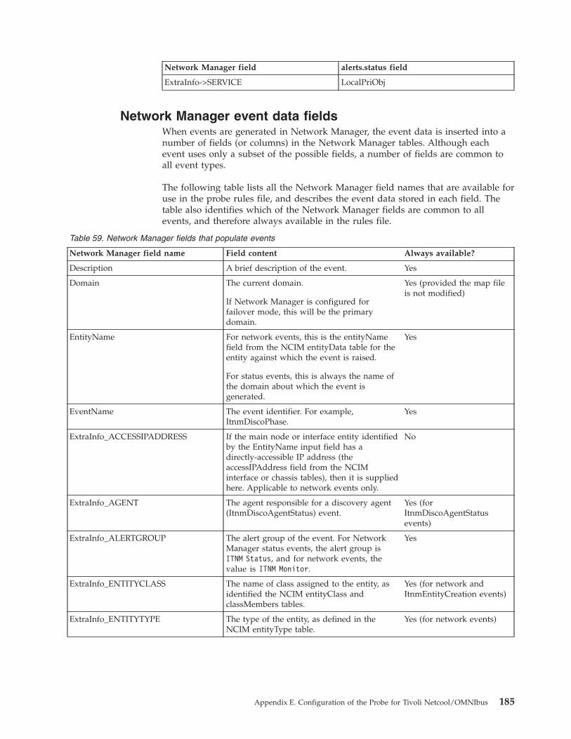
Network Manager field alerts.status field
ExtraInfo->SERVICE LocalPriObj
Network Manager event data fieldsWhen events are generated in Network Manager, the event data is inserted into anumber of fields (or columns) in the Network Manager tables. Although eachevent uses only a subset of the possible fields, a number of fields are common toall event types.
The following table lists all the Network Manager field names that are available foruse in the probe rules file, and describes the event data stored in each field. Thetable also identifies which of the Network Manager fields are common to allevents, and therefore always available in the rules file.
Table 59. Network Manager fields that populate events
Network Manager field name Field content Always available?
Description A brief description of the event. Yes
Domain The current domain.
If Network Manager is configured forfailover mode, this will be the primarydomain.
Yes (provided the map fileis not modified)
EntityName For network events, this is the entityNamefield from the NCIM entityData table for theentity against which the event is raised.
For status events, this is always the name ofthe domain about which the event isgenerated.
Yes
EventName The event identifier. For example,ItnmDiscoPhase.
Yes
ExtraInfo_ACCESSIPADDRESS If the main node or interface entity identifiedby the EntityName input field has adirectly-accessible IP address (theaccessIPAddress field from the NCIMinterface or chassis tables), then it is suppliedhere. Applicable to network events only.
No
ExtraInfo_AGENT The agent responsible for a discovery agent(ItnmDiscoAgentStatus) event.
Yes (forItnmDiscoAgentStatusevents)
ExtraInfo_ALERTGROUP The alert group of the event. For NetworkManager status events, the alert group isITNM Status, and for network events, thevalue is ITNM Monitor.
Yes
ExtraInfo_ENTITYCLASS The name of class assigned to the entity, asidentified the NCIM entityClass andclassMembers tables.
Yes (for network andItnmEntityCreation events)
ExtraInfo_ENTITYTYPE The type of the entity, as defined in theNCIM entityType table.
Yes (for network events)
Appendix E. Configuration of the Probe for Tivoli Netcool/OMNIbus 185
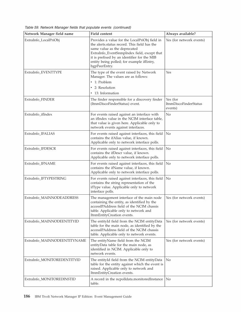
Table 59. Network Manager fields that populate events (continued)
Network Manager field name Field content Always available?
ExtraInfo_LocalPriObj Provides a value for the LocalPriObj field inthe alerts.status record. This field has thesame value as the deprecatedExtraInfo_EventSnmpIndex field, except thatit is prefixed by an identifier for the MIBentity being polled; for example ifEntry,bgpPeerEntry.
Yes (for network events)
ExtraInfo_EVENTTYPE The type of the event raised by NetworkManager. The values are as follows:
v 1: Problem
v 2: Resolution
v 13: Information
Yes
ExtraInfo_FINDER The finder responsible for a discovery finder(ItnmDiscoFinderStatus) event.
Yes (forItnmDiscoFinderStatusevents)
ExtraInfo_ifIndex For events raised against an interface withan ifIndex value in the NCIM interface table,that value is given here. Applicable only tonetwork events against interfaces.
No
ExtraInfo_IFALIAS For events raised against interfaces, this fieldcontains the ifAlias value, if known.Applicable only to network interface polls.
No
ExtraInfo_IFDESCR For events raised against interfaces, this fieldcontains the ifDescr value, if known.Applicable only to network interface polls.
No
ExtraInfo_IFNAME For events raised against interfaces, this fieldcontains the ifName value, if known.Applicable only to network interface polls.
No
ExtraInfo_IFTYPESTRING For events raised against interfaces, this fieldcontains the string representation of theifType value. Applicable only to networkinterface polls.
No
ExtraInfo_MAINNODEADDRESS The management interface of the main nodecontaining the entity, as identified by theaccessIPAddress field of the NCIM chassistable. Applicable only to network andItnmEntityCreation events.
Yes (for network events)
ExtraInfo_MAINNODEENTITYID The entityId field from the NCIM entityDatatable for the main node, as identified by theaccessIPAddress field of the NCIM chassistable. Applicable only to network events.
Yes (for network events)
ExtraInfo_MAINNODEENTITYNAME The entityName field from the NCIMentityData table for the main node, asidentified in NCIM. Applicable only tonetwork events.
Yes (for network events)
ExtraInfo_MONITOREDENTITYID The entityId field from the NCIM entityDatatable for the entity against which the event israised. Applicable only to network andItnmEntityCreation events.
No
ExtraInfo_MONITOREDINSTID A record in the ncpolldata.monitoredInstancetable.
No
186 IBM Tivoli Network Manager IP Edition: Event Management Guide
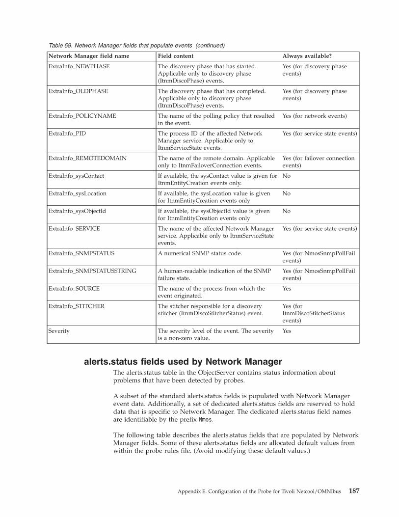
Table 59. Network Manager fields that populate events (continued)
Network Manager field name Field content Always available?
ExtraInfo_NEWPHASE The discovery phase that has started.Applicable only to discovery phase(ItnmDiscoPhase) events.
Yes (for discovery phaseevents)
ExtraInfo_OLDPHASE The discovery phase that has completed.Applicable only to discovery phase(ItnmDiscoPhase) events.
Yes (for discovery phaseevents)
ExtraInfo_POLICYNAME The name of the polling policy that resultedin the event.
Yes (for network events)
ExtraInfo_PID The process ID of the affected NetworkManager service. Applicable only toItnmServiceState events.
Yes (for service state events)
ExtraInfo_REMOTEDOMAIN The name of the remote domain. Applicableonly to ItnmFailoverConnection events.
Yes (for failover connectionevents)
ExtraInfo_sysContact If available, the sysContact value is given forItnmEntityCreation events only.
No
ExtraInfo_sysLocation If available, the sysLocation value is givenfor ItnmEntityCreation events only
No
ExtraInfo_sysObjectId If available, the sysObjectId value is givenfor ItnmEntityCreation events only
No
ExtraInfo_SERVICE The name of the affected Network Managerservice. Applicable only to ItnmServiceStateevents.
Yes (for service state events)
ExtraInfo_SNMPSTATUS A numerical SNMP status code. Yes (for NmosSnmpPollFailevents)
ExtraInfo_SNMPSTATUSSTRING A human-readable indication of the SNMPfailure state.
Yes (for NmosSnmpPollFailevents)
ExtraInfo_SOURCE The name of the process from which theevent originated.
Yes
ExtraInfo_STITCHER The stitcher responsible for a discoverystitcher (ItnmDiscoStitcherStatus) event.
Yes (forItnmDiscoStitcherStatusevents)
Severity The severity level of the event. The severityis a non-zero value.
Yes
alerts.status fields used by Network ManagerThe alerts.status table in the ObjectServer contains status information aboutproblems that have been detected by probes.
A subset of the standard alerts.status fields is populated with Network Managerevent data. Additionally, a set of dedicated alerts.status fields are reserved to holddata that is specific to Network Manager. The dedicated alerts.status field namesare identifiable by the prefix Nmos.
The following table describes the alerts.status fields that are populated by NetworkManager fields. Some of these alerts.status fields are allocated default values fromwithin the probe rules file. (Avoid modifying these default values.)
Appendix E. Configuration of the Probe for Tivoli Netcool/OMNIbus 187
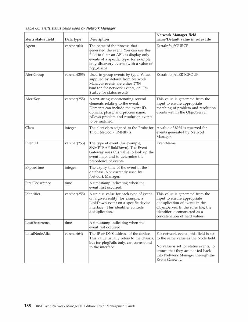
Table 60. alerts.status fields used by Network Manager
alerts.status field Data type DescriptionNetwork Manager fieldname/Default value in rules file
Agent varchar(64) The name of the process thatgenerated the event. You can use thisfield to filter an AEL to display onlyevents of a specific type; for example,only discovery events (with a value ofncp_disco).
ExtraInfo_SOURCE
AlertGroup varchar(255) Used to group events by type. Valuessupplied by default from NetworkManager events are either ITNMMonitor for network events, or ITNMStatus for status events.
ExtraInfo_ALERTGROUP
AlertKey varchar(255) A text string concatenating severalelements relating to the event.Elements can include the event ID,domain, phase, and process name.Allows problem and resolution eventsto be matched.
This value is generated from theinput to ensure appropriatematching of problem and resolutionevents within the ObjectServer.
Class integer The alert class asigned to the Probe forTivoli Netcool/OMNIbus.
A value of 8000 is reserved forevents generated by NetworkManager.
EventId varchar(255) The type of event (for example,SNMPTRAP-linkDown). The EventGateway uses this value to look up theevent map, and to determine theprecedence of events.
EventName
ExpireTime integer The expiry time of the event in thedatabase. Not currently used byNetwork Manager.
FirstOccurrence time A timestamp indicating when theevent first occurred.
Identifier varchar(255) A unique value for each type of eventon a given entity (for example, aLinkDown event on a specific deviceinterface). This identifier controlsdeduplication.
This value is generated from theinput to ensure appropriatededuplication of events in theObjectServer. In the rules file, theidentifier is constructed as aconcatenation of field values.
LastOccurrence time A timestamp indicating when theevent last occurred.
LocalNodeAlias varchar(64) The IP or DNS address of the device.This value usually refers to the chassis,but for pingFails only, can correspondto the interface.
For network events, this field is setto the same value as the Node field.
No value is set for status events, toensure that they are not fed backinto Network Manager through theEvent Gateway.
188 IBM Tivoli Network Manager IP Edition: Event Management Guide
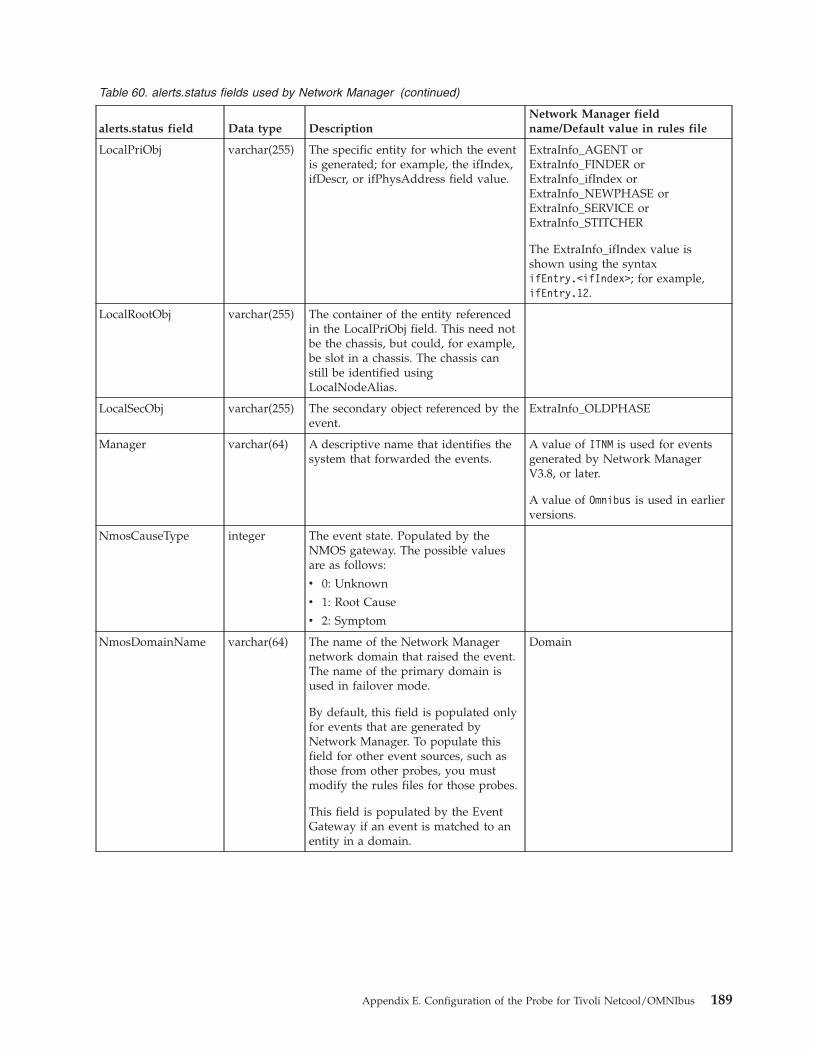
Table 60. alerts.status fields used by Network Manager (continued)
alerts.status field Data type DescriptionNetwork Manager fieldname/Default value in rules file
LocalPriObj varchar(255) The specific entity for which the eventis generated; for example, the ifIndex,ifDescr, or ifPhysAddress field value.
ExtraInfo_AGENT orExtraInfo_FINDER orExtraInfo_ifIndex orExtraInfo_NEWPHASE orExtraInfo_SERVICE orExtraInfo_STITCHER
The ExtraInfo_ifIndex value isshown using the syntaxifEntry.<ifIndex>; for example,ifEntry.12.
LocalRootObj varchar(255) The container of the entity referencedin the LocalPriObj field. This need notbe the chassis, but could, for example,be slot in a chassis. The chassis canstill be identified usingLocalNodeAlias.
LocalSecObj varchar(255) The secondary object referenced by theevent.
ExtraInfo_OLDPHASE
Manager varchar(64) A descriptive name that identifies thesystem that forwarded the events.
A value of ITNM is used for eventsgenerated by Network ManagerV3.8, or later.
A value of Omnibus is used in earlierversions.
NmosCauseType integer The event state. Populated by theNMOS gateway. The possible valuesare as follows:
v 0: Unknown
v 1: Root Cause
v 2: Symptom
NmosDomainName varchar(64) The name of the Network Managernetwork domain that raised the event.The name of the primary domain isused in failover mode.
By default, this field is populated onlyfor events that are generated byNetwork Manager. To populate thisfield for other event sources, such asthose from other probes, you mustmodify the rules files for those probes.
This field is populated by the EventGateway if an event is matched to anentity in a domain.
Domain
Appendix E. Configuration of the Probe for Tivoli Netcool/OMNIbus 189
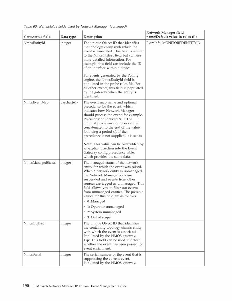
Table 60. alerts.status fields used by Network Manager (continued)
alerts.status field Data type DescriptionNetwork Manager fieldname/Default value in rules file
NmosEntityId integer The unique Object ID that identifiesthe topology entity with which theevent is associated. This field is similarto the NmosObjInst field but containsmore detailed information. Forexample, this field can include the IDof an interface within a device.
For events generated by the Pollingengine, the NmosEntityId field ispopulated in the probe rules file. Forall other events, this field is populatedby the gateway when the entity isidentified.
ExtraInfo_MONITOREDENTITYID
NmosEventMap varchar(64) The event map name and optionalprecedence for the event, whichindicates how Network Managershould process the event; for example,PrecisionMonitorEvent.910. Theoptional precedence number can beconcatenated to the end of the value,following a period (.). If theprecedence is not supplied, it is set to0.Note: This value can be overridden byan explicit insertion into the EventGateway config.precedence table,which provides the same data.
NmosManagedStatus integer The managed status of the networkentity for which the event was raised.When a network entity is unmanaged,the Network Manager polls aresuspended and events from othersources are tagged as unmanaged. Thisfield allows you to filter out eventsfrom unmanaged entities. The possiblevalues for this field are as follows:
v 0: Managed
v 1: Operator unmanaged
v 2: System unmanaged
v 3: Out of scope
NmosObjInst integer The unique Object ID that identifiesthe containing topology chassis entitywith which the event is associated.Populated by the NMOS gateway.Tip: This field can be used to detectwhether the event has been passed forevent enrichment.
NmosSerial integer The serial number of the event that issuppressing the current event.Populated by the NMOS gateway.
190 IBM Tivoli Network Manager IP Edition: Event Management Guide
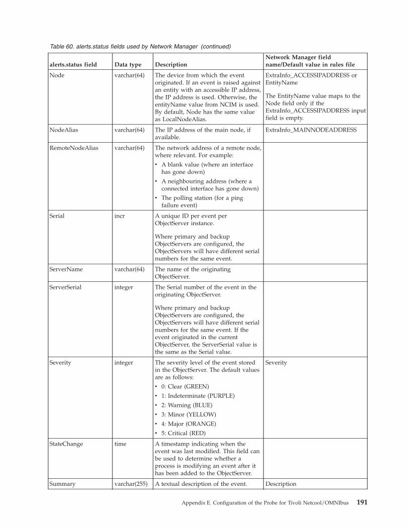
Table 60. alerts.status fields used by Network Manager (continued)
alerts.status field Data type DescriptionNetwork Manager fieldname/Default value in rules file
Node varchar(64) The device from which the eventoriginated. If an event is raised againstan entity with an accessible IP address,the IP address is used. Otherwise, theentityName value from NCIM is used.By default, Node has the same valueas LocalNodeAlias.
ExtraInfo_ACCESSIPADDRESS orEntityName
The EntityName value maps to theNode field only if theExtraInfo_ACCESSIPADDRESS inputfield is empty.
NodeAlias varchar(64) The IP address of the main node, ifavailable.
ExtraInfo_MAINNODEADDRESS
RemoteNodeAlias varchar(64) The network address of a remote node,where relevant. For example:
v A blank value (where an interfacehas gone down)
v A neighbouring address (where aconnected interface has gone down)
v The polling station (for a pingfailure event)
Serial incr A unique ID per event perObjectServer instance.
Where primary and backupObjectServers are configured, theObjectServers will have different serialnumbers for the same event.
ServerName varchar(64) The name of the originatingObjectServer.
ServerSerial integer The Serial number of the event in theoriginating ObjectServer.
Where primary and backupObjectServers are configured, theObjectServers will have different serialnumbers for the same event. If theevent originated in the currentObjectServer, the ServerSerial value isthe same as the Serial value.
Severity integer The severity level of the event storedin the ObjectServer. The default valuesare as follows:
v 0: Clear (GREEN)
v 1: Indeterminate (PURPLE)
v 2: Warning (BLUE)
v 3: Minor (YELLOW)
v 4: Major (ORANGE)
v 5: Critical (RED)
Severity
StateChange time A timestamp indicating when theevent was last modified. This field canbe used to determine whether aprocess is modifying an event after ithas been added to the ObjectServer.
Summary varchar(255) A textual description of the event. Description
Appendix E. Configuration of the Probe for Tivoli Netcool/OMNIbus 191
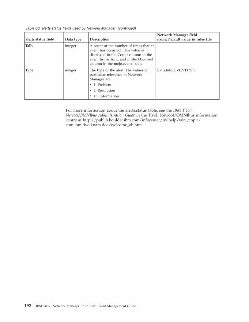
Table 60. alerts.status fields used by Network Manager (continued)
alerts.status field Data type DescriptionNetwork Manager fieldname/Default value in rules file
Tally integer A count of the number of times that anevent has occurred. This value isdisplayed in the Count column in theevent list or AEL, and in the Occurredcolumn in the mojo.events table.
Type integer The type of the alert. The values ofparticular relevance to NetworkManager are
v 1: Problem
v 2: Resolution
v 13: Information
ExtraInfo_EVENTTYPE
For more information about the alerts.status table, see the IBM TivoliNetcool/OMNIbus Administration Guide in the Tivoli Netcool/OMNIbus informationcentre at http://publib.boulder.ibm.com/infocenter/tivihelp/v8r1/topic/com.ibm.tivoli.nam.doc/welcome_ob.htm.
192 IBM Tivoli Network Manager IP Edition: Event Management Guide
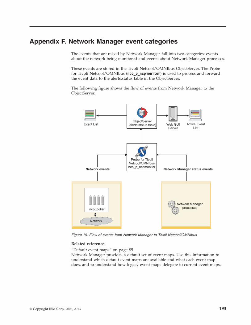
Appendix F. Network Manager event categories
The events that are raised by Network Manager fall into two categories: eventsabout the network being monitored and events about Network Manager processes.
These events are stored in the Tivoli Netcool/OMNIbus ObjectServer. The Probefor Tivoli Netcool/OMNIbus (nco_p_ncpmonitor) is used to process and forwardthe event data to the alerts.status table in the ObjectServer.
The following figure shows the flow of events from Network Manager to theObjectServer.
Related reference:“Default event maps” on page 85Network Manager provides a default set of event maps. Use this information tounderstand which default event maps are available and what each event mapdoes, and to understand how legacy event maps delegate to current event maps.
Network Managerprocesses
Network
ncp_poller
Active EventList
Probe for TivoliNetcool/OMNIbusnco_p_ncpmonitor
ObjectServer[alerts.status table]Event List Web GUI
Server
Network events Network Manager status events
Figure 15. Flow of events from Network Manager to Tivoli Netcool/OMNIbus
© Copyright IBM Corp. 2006, 2013 193
Network Manager network eventsThe Polling engine, ncp_poller, generates events about the state of the network.These events can be used to identify network problems, and are configurable byusing the Network Polling GUI (go to Administration > Network > NetworkPolling). These events are known as network events and have the alerts.statusAlertGroup field value of ITNM Monitor.
Each network event is raised on a single entity, such as an interface or a chassis,and the event data is dependent on the type of poll. When network events areforwarded to the ObjectServer for insertion into the alerts.status table, they areallocated an AlertGroup value of ITNM Monitor.
An unlimited set of event identifiers is available for network events. Events thatare generated when an SNMP poll fails are specifically allocated an EventID valueof NmosSnmpPollFail in the alerts.status table.
Network events in the ObjectServer are pulled back into Network Managerthrough the Event Gateway to perform event enrichment, including root causeanalysis.
Network Manager status eventsNetwork Manager can generate events that show the status of various NetworkManager processes. These events are known as Network Manager status eventsand have the alerts.status AlertGroup field value of ITNM Status.
When these status events are forwarded to the ObjectServer for insertion into thealerts.status table, they are allocated an AlertGroup value of ITNM Status.
Status event types
A set of event identifiers is used to identify Network Manager status events bytype. The following list identifies the EventId values that are inserted in thealerts.status table, and describes how each associated status event is generated.
ItnmDatabaseConnectionThis type of event is generated to indicate loss of connection to NCIM.This event is generated by the managed status polling thread in thencp_model process. The raising of this event depends on the time periodconfigured in the managed status polling interval in model. A problemevent is raised if the connection is lost, and a corresponding resolutionevent is raised if the connection is restored, or at startup to clear anyfailures from a previous operation. This event type allows the backupdomain to take over when failover is configured. The virtual domainprocess reacts to this event as defined in the filter for NCIM in theNCHOME/etc/precision/VirtualDomainSchema.cfg file.
ItnmDiscoAgentStatusThis type of event is generated by ncp_disco when a discovery agenttransitions to a new state. At the end of a discovery, an information eventis forwarded to the ObjectServer, for each agent that was used during thediscovery.
You can use this information to identify the state of each agent. In thealerts.status table, the LocalPriObj field is used to store the name of theagent.
194 IBM Tivoli Network Manager IP Edition: Event Management Guide
Discovery agent events in the ObjectServer are overwritten when asubsequent discovery is run.
ItnmDiscoFinderStatusThis type of event is generated by ncp_disco when a discovery findertransitions to a new state. At the end of a discovery, an information eventis forwarded to the ObjectServer, for each finder that was used during thediscovery.
You can use this information to identify which finders are running andtheir state. In the alerts.status table, the LocalPriObj field is used to storethe name of the finder.
Discovery finder events in the ObjectServer are overwritten when asubsequent discovery is run.
ItnmDiscoPhaseThis type of event is generated by ncp_disco when the discovery processtransitions to a new phase. At the end of the discovery, five informationevents should be present in the ObjectServer, to show the loopedtransitions from phase 0 (standby) to phases 1, 2, and 3 (data collection) tophase -1 (data processing). An event is raised for each of the followingphase changes in a single discovery:v 0 to 1v 1 to 2v 2 to 3v 3 to -1v -1 to 0
You can use this information to determine the length of each phase. In thealerts.status table, the LocalPriObj field is used to store the phase to whichthe discovery is transitioning, and the LocalSecObj field stores the previousphase of the discovery.
Tip: The string values for the phases are also shown in the discovery logfile when the ncp_disco process is run in debug mode.
Discovery phase events in the ObjectServer are overwritten when asubsequent discovery is run.
ItnmDiscoStitcherStatusThe discovery process is made up of a data collection stage and a dataprocessing stage, during which the topology is created.ItnmDiscoStitcherStatus events are generated by the Discovery engine,ncp_disco, when a major phase is reached in the data processing stage. Atthe end of the discovery, an information event is forwarded to theObjectServer, for each major discovery stitcher that was used during thediscovery.
You can use this information to identify what phase in the data processingstage the discovery is in. In the alerts.status table, the LocalPriObj field isused to store the name of the stitcher corresponding to this phase.
ItnmDiscoStitcherStatus events are raised when the following stitchersbegin executing:v BuildFinalEntityTablev BuildContainmentv BuildLayers
Appendix F. Network Manager event categories 195
v MergeLayersv PostLayerProcessing
Subsequently events are raised during the topology creation phase whenthe following stitchers are run.v If ncp_disco is using the dNCIM database:
– PopulateDNCIM
Discovery stitcher events in the ObjectServer are overwritten when asubsequent discovery is run.
ItnmEntityCreationIf configured in the $NCHOME/etc/precision/ModelSchema.cfg file, this typeof information event is generated by ncp_model, for each new chassis or IPinterface entity (EntityType = 1) that is inserted into the NCIM database.
You can configure ModelSchema.cfg by setting the value of theRaiseEntityEvent column to 1 in the INSERT statement for themodel.config table. For example:create table model.config(LingerTime int not null primary key, // default value 3 (discoveries)RaiseEntityEvent int type boolean not null, // default value 0 ( off )DiscoveryUpdateMode int not null, // default value 0 - full discovery,
// 1 - partialunique(LingerTime));insert into model.config values (3, 1, 0);
Note: For the configuration changes to take effect and enable the events,the ncp_model process must be restarted. The process reads theconfiguration settings at start-up.
ItnmEntityDeletionIf configured in the $NCHOME/etc/precision/ModelSchema.cfg file, this typeof information event is generated by ncp_model, for each chassis or IPinterface entity (EntityType = 1) that is deleted from the NCIM database.
You can configure ModelSchema.cfg by setting the value of theRaiseEntityEvent column to 1 in the INSERT statement for themodel.config table, as shown in the preceding description for theItnmEntityCreation EventId.
ItnmFailoverThis type of event is generated by ncp_virtualdomain when a NetworkManager domain within a failover pair fails over or fails back.
A problem event is generated when failover occurs and a resolution eventis generated on failback.
In the alerts.status table, the Summary field description indicates whetherthe domain is the primary or backup, and whether it is in an active or astandby mode.
ItnmFailoverConnectionThis type of event is generated by ncp_virtualdomain to indicate when thebackup domain in a failover pair connects to, or disconnects from, theprimary domain.
When Network Manager runs in failover mode, a resolution event isgenerated when the primary and backup domains set up their TCP socketconnection. This socket connection is required to transfer the topologyupdates from the primary domain because the discovery process
196 IBM Tivoli Network Manager IP Edition: Event Management Guide

(ncp_disco) does not run in the backup domain. If the connection issubsequently lost, a problem event is generated.
Note: The status of the connection does not determine whether failover istriggered. Failover is triggered only when health check events aretransferred (via the ObjectServer) across domains, and provided a socketconnection has, at some point, been established.
ItnmHealthChkHealth check events govern Network Manager failover. Each domain in thefailover pair generates health check resolution events while that domain ishealthy.
Health check problem events for a domain can be generated in two ways:v By the local domain: The local domain detects a failure of one of its
processes, as configured in the $NCHOME/etc/precision/VirtualDomainSchema.cfg file.
v By the remote domain: One domain detects that the other domain hasnot generated a health check resolution event in the configured amountof time, and generates a synthetic health check problem event on behalfof the remote domain.
When a health check problem event is generated for the primary domain,failover is initiated, and the backup domain becomes active.
Health check events were previously allocated an EventID value ofNcpHealthChk. For compatibility with earlier versions of NetworkManager, you can substitute NcpHealthChk in place of ItnmHealthChk inthe probe rules file.
Note: Health check events are handled by the Network Manager EventGateway, which requires the Node value to be the domain to which theevent refers. This need not be the domain raising the event, since onedomain can raise failure events on behalf of the other.
ItnmMaintenanceStateIf configured in the $NCHOME/etc/precision/ModelSchema.cfg file, this typeof event is generated by the Topology manager, ncp_model, for maintenancestatus changes to a chassis or an IP interface.
You can configure ModelSchema.cfg by setting the value of theRaiseEntityEvent column to 1 in the INSERT statement for themodel.config table, as shown in the preceding description for theItnmEntityCreation event.
A problem event is generated when the chassis or IP interface entity is inmaintenance, and a resolution event is generated when the entity is out ofmaintenance.
Note: An individual interface event is sent only if the change does notapply at the chassis level; when a device changes, a chassis event and aseries of interface events are not collectively generated.
ItnmServiceStateThis type of event is generated when a process starts or ends, and signifieswhether a process has failed to start or has stopped during runtime. (Notethat process state events are not generated when processes are stopped atsystem shutdown.)
Appendix F. Network Manager event categories 197
A resolution event is generated when ncp_ctrl starts a process. If a processfails to start or if it stops during runtime, a problem event is generated.
In the alerts.status table, the Summary field description includes theprocess name, the PID, and an indication of whether the process has:v Started (and successfully initialized)v Stopped (that is, it has been deleted from the ncp_ctrl database table
named services.inTray)v Terminated (that is, it stopped, but will be restarted by ncp_ctrl)v Failed to startv Failed and will not be restarted (that is, it stopped and the number of
retries configured for the process has been exceeded)
ItnmTopologyUpdatedThis type of information event is generated by ncp_model when the updateof the NCIM topology database is completed at the end of a discoverycycle. This information is useful if you intend to program scripts orprocedures to run after the NCIM database is updated.
Note: If the feedback option is on, or large subnets are pinged, there mightbe multiple discovery cycles and thus multiple events of this type, oneevent for each discovery cycle. To determine if discovery has finallyfinished, the following OQL query can be made to the Ping Finder service:select * from pingFinder.status where m_Completed <> 1;
This query looks for any subnets that the Ping finder is still pinging. Ifthere are no outstanding ping sweeps and the discovery is in phase 0, thismeans that the discovery is complete.
198 IBM Tivoli Network Manager IP Edition: Event Management Guide
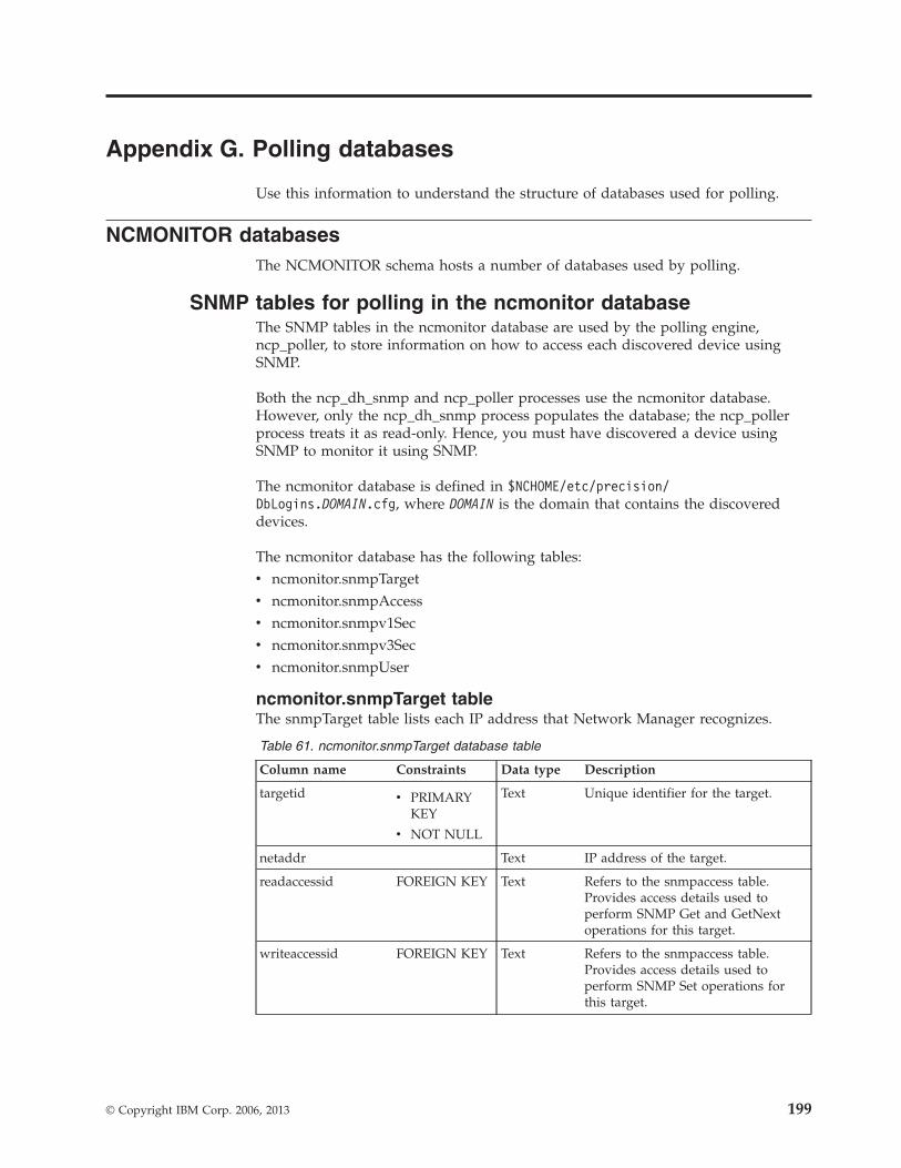
Appendix G. Polling databases
Use this information to understand the structure of databases used for polling.
NCMONITOR databasesThe NCMONITOR schema hosts a number of databases used by polling.
SNMP tables for polling in the ncmonitor databaseThe SNMP tables in the ncmonitor database are used by the polling engine,ncp_poller, to store information on how to access each discovered device usingSNMP.
Both the ncp_dh_snmp and ncp_poller processes use the ncmonitor database.However, only the ncp_dh_snmp process populates the database; the ncp_pollerprocess treats it as read-only. Hence, you must have discovered a device usingSNMP to monitor it using SNMP.
The ncmonitor database is defined in $NCHOME/etc/precision/DbLogins.DOMAIN.cfg, where DOMAIN is the domain that contains the discovereddevices.
The ncmonitor database has the following tables:v ncmonitor.snmpTargetv ncmonitor.snmpAccessv ncmonitor.snmpv1Secv ncmonitor.snmpv3Secv ncmonitor.snmpUser
ncmonitor.snmpTarget tableThe snmpTarget table lists each IP address that Network Manager recognizes.
Table 61. ncmonitor.snmpTarget database table
Column name Constraints Data type Description
targetid v PRIMARYKEY
v NOT NULL
Text Unique identifier for the target.
netaddr Text IP address of the target.
readaccessid FOREIGN KEY Text Refers to the snmpaccess table.Provides access details used toperform SNMP Get and GetNextoperations for this target.
writeaccessid FOREIGN KEY Text Refers to the snmpaccess table.Provides access details used toperform SNMP Set operations forthis target.
© Copyright IBM Corp. 2006, 2013 199
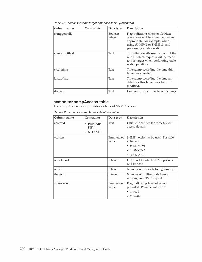
Table 61. ncmonitor.snmpTarget database table (continued)
Column name Constraints Data type Description
snmpgetbulk Booleaninteger
Flag indicating whether GetNextoperations will be attempted whenappropriate; for example, whenusing SNMPv2 or SNMPv3, andperforming a table walk.
snmpthrottleid Text Throttling details used to control therate at which requests will be madeto this target when performing tablewalk operations.
createtime Text Timestamp recording the time thistarget was created.
lastupdate Text Timestamp recording the time anydetail for this target was lastmodified.
domain Text Domain to which this target belongs.
ncmonitor.snmpAccess tableThe snmpAccess table provides details of SNMP access.
Table 62. ncmonitor.snmpAccess database table
Column name Constraints Data type Description
accessid v PRIMARYKEY
v NOT NULL
Text Unique identifier for these SNMPaccess details.
version Enumeratedvalue
SNMP version to be used. Possiblevalue are:
v 0: SNMPv1
v 1: SNMPv2
v 3: SNMPv3
remoteport Integer UDP port to which SNMP packetswill be sent.
retries Integer Number of retries before giving up.
timeout Integer Number of milliseconds beforeretrying an SNMP request .
accesslevel Enumeratedvalue
Flag indicating level of accessprovided. Possible values are:
v 1: read
v 2: write
200 IBM Tivoli Network Manager IP Edition: Event Management Guide
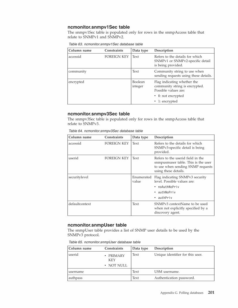
ncmonitor.snmpv1Sec tableThe snmpv1Sec table is populated only for rows in the snmpAccess table thatrelate to SNMPv1 and SNMPv2.
Table 63. ncmonitor.snmpv1Sec database table
Column name Constraints Data type Description
accessid FOREIGN KEY Text Refers to the details for whichSNMPv1 or SNMPv2-specific detailis being provided.
community Text Community string to use whensending requests using these details.
encrypted Booleaninteger
Flag indicating whether thecommunity string is encrypted.Possible values are:
v 0: not encrypted
v 1: encrypted
ncmonitor.snmpv3Sec tableThe snmpv3Sec table is populated only for rows in the snmpAccess table thatrelate to SNMPv3.
Table 64. ncmonitor.snmpv3Sec database table
Column name Constraints Data type Description
accessid FOREIGN KEY Text Refers to the details for whichSNMPv3-specific detail is beingprovided.
userid FOREIGN KEY Text Refers to the userid field in thesnmpusmuser table. This is the userto use when sending SNMP requestsusing these details.
securitylevel Enumeratedvalue
Flag indicating SNMPv3 securitylevel. Possible values are:
v noAuthNoPriv
v authNoPriv
v authPriv
defaultcontext Text SNMPv3 contextName to be usedwhen not explicitly specified by adiscovery agent.
ncmonitor.snmpUser tableThe snmpUser table provides a list of SNMP user details to be used by theSNMPv3 protocol.
Table 65. ncmonitor.snmpUser database table
Column name Constraints Data type Description
userid v PRIMARYKEY
v NOT NULL
Text Unique identifier for this user.
username Text USM username.
authpass Text Authentication password.
Appendix G. Polling databases 201
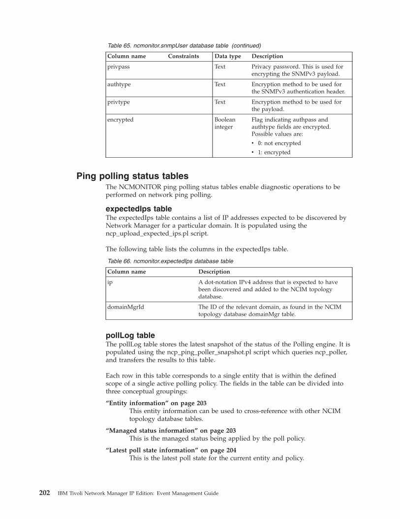
Table 65. ncmonitor.snmpUser database table (continued)
Column name Constraints Data type Description
privpass Text Privacy password. This is used forencrypting the SNMPv3 payload.
authtype Text Encryption method to be used forthe SNMPv3 authentication header.
privtype Text Encryption method to be used forthe payload.
encrypted Booleaninteger
Flag indicating authpass andauthtype fields are encrypted.Possible values are:
v 0: not encrypted
v 1: encrypted
Ping polling status tablesThe NCMONITOR ping polling status tables enable diagnostic operations to beperformed on network ping polling.
expectedIps tableThe expectedIps table contains a list of IP addresses expected to be discovered byNetwork Manager for a particular domain. It is populated using thencp_upload_expected_ips.pl script.
The following table lists the columns in the expectedIps table.
Table 66. ncmonitor.expectedIps database table
Column name Description
ip A dot-notation IPv4 address that is expected to havebeen discovered and added to the NCIM topologydatabase.
domainMgrId The ID of the relevant domain, as found in the NCIMtopology database domainMgr table.
pollLog tableThe pollLog table stores the latest snapshot of the status of the Polling engine. It ispopulated using the ncp_ping_poller_snapshot.pl script which queries ncp_poller,and transfers the results to this table.
Each row in this table corresponds to a single entity that is within the definedscope of a single active polling policy. The fields in the table can be divided intothree conceptual groupings:
“Entity information” on page 203This entity information can be used to cross-reference with other NCIMtopology database tables.
“Managed status information” on page 203This is the managed status being applied by the poll policy.
“Latest poll state information” on page 204This is the latest poll state for the current entity and policy.
202 IBM Tivoli Network Manager IP Edition: Event Management Guide
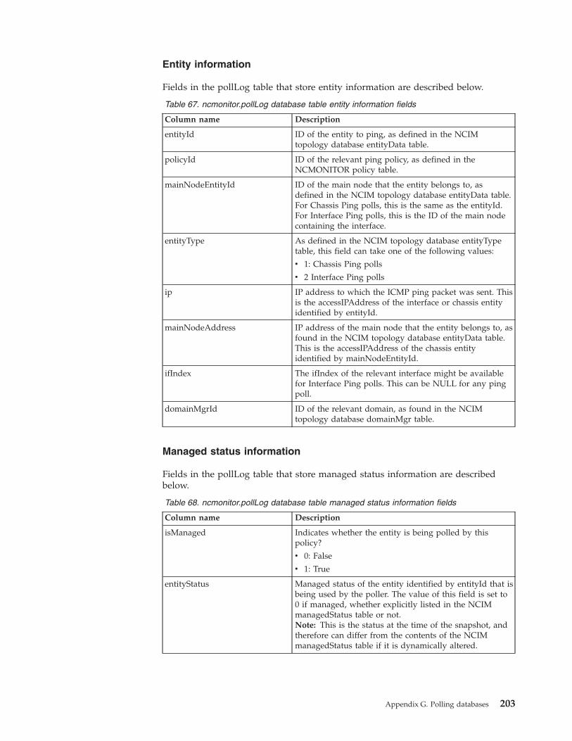
Entity information
Fields in the pollLog table that store entity information are described below.
Table 67. ncmonitor.pollLog database table entity information fields
Column name Description
entityId ID of the entity to ping, as defined in the NCIMtopology database entityData table.
policyId ID of the relevant ping policy, as defined in theNCMONITOR policy table.
mainNodeEntityId ID of the main node that the entity belongs to, asdefined in the NCIM topology database entityData table.For Chassis Ping polls, this is the same as the entityId.For Interface Ping polls, this is the ID of the main nodecontaining the interface.
entityType As defined in the NCIM topology database entityTypetable, this field can take one of the following values:
v 1: Chassis Ping polls
v 2 Interface Ping polls
ip IP address to which the ICMP ping packet was sent. Thisis the accessIPAddress of the interface or chassis entityidentified by entityId.
mainNodeAddress IP address of the main node that the entity belongs to, asfound in the NCIM topology database entityData table.This is the accessIPAddress of the chassis entityidentified by mainNodeEntityId.
ifIndex The ifIndex of the relevant interface might be availablefor Interface Ping polls. This can be NULL for any pingpoll.
domainMgrId ID of the relevant domain, as found in the NCIMtopology database domainMgr table.
Managed status information
Fields in the pollLog table that store managed status information are describedbelow.
Table 68. ncmonitor.pollLog database table managed status information fields
Column name Description
isManaged Indicates whether the entity is being polled by thispolicy?
v 0: False
v 1: True
entityStatus Managed status of the entity identified by entityId that isbeing used by the poller. The value of this field is set to0 if managed, whether explicitly listed in the NCIMmanagedStatus table or not.Note: This is the status at the time of the snapshot, andtherefore can differ from the contents of the NCIMmanagedStatus table if it is dynamically altered.
Appendix G. Polling databases 203
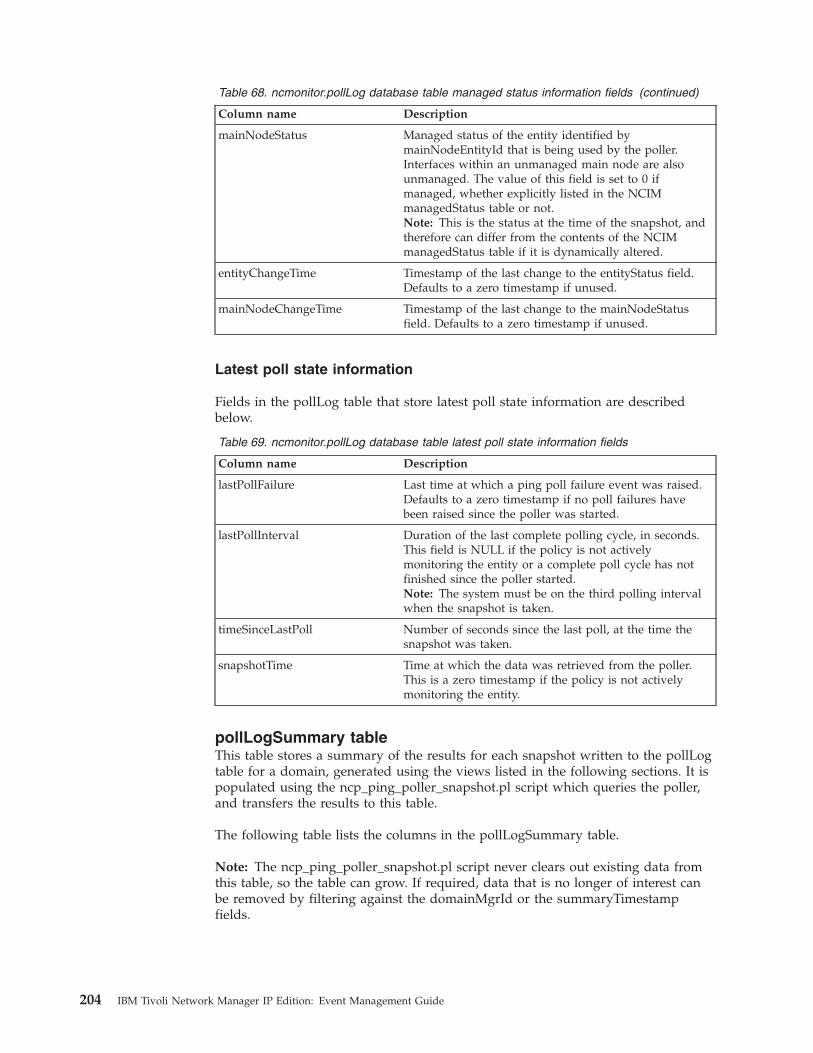
Table 68. ncmonitor.pollLog database table managed status information fields (continued)
Column name Description
mainNodeStatus Managed status of the entity identified bymainNodeEntityId that is being used by the poller.Interfaces within an unmanaged main node are alsounmanaged. The value of this field is set to 0 ifmanaged, whether explicitly listed in the NCIMmanagedStatus table or not.Note: This is the status at the time of the snapshot, andtherefore can differ from the contents of the NCIMmanagedStatus table if it is dynamically altered.
entityChangeTime Timestamp of the last change to the entityStatus field.Defaults to a zero timestamp if unused.
mainNodeChangeTime Timestamp of the last change to the mainNodeStatusfield. Defaults to a zero timestamp if unused.
Latest poll state information
Fields in the pollLog table that store latest poll state information are describedbelow.
Table 69. ncmonitor.pollLog database table latest poll state information fields
Column name Description
lastPollFailure Last time at which a ping poll failure event was raised.Defaults to a zero timestamp if no poll failures havebeen raised since the poller was started.
lastPollInterval Duration of the last complete polling cycle, in seconds.This field is NULL if the policy is not activelymonitoring the entity or a complete poll cycle has notfinished since the poller started.Note: The system must be on the third polling intervalwhen the snapshot is taken.
timeSinceLastPoll Number of seconds since the last poll, at the time thesnapshot was taken.
snapshotTime Time at which the data was retrieved from the poller.This is a zero timestamp if the policy is not activelymonitoring the entity.
pollLogSummary tableThis table stores a summary of the results for each snapshot written to the pollLogtable for a domain, generated using the views listed in the following sections. It ispopulated using the ncp_ping_poller_snapshot.pl script which queries the poller,and transfers the results to this table.
The following table lists the columns in the pollLogSummary table.
Note: The ncp_ping_poller_snapshot.pl script never clears out existing data fromthis table, so the table can grow. If required, data that is no longer of interest canbe removed by filtering against the domainMgrId or the summaryTimestampfields.
204 IBM Tivoli Network Manager IP Edition: Event Management Guide
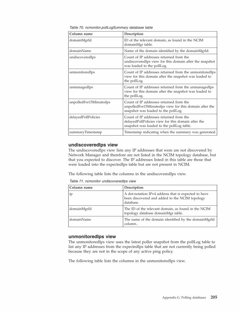
Table 70. ncmonitor.pollLogSummary database table
Column name Description
domainMgrId ID of the relevant domain, as found in the NCIMdomainMgr table.
domainName Name of the domain identified by the domainMgrId.
undiscoveredIps Count of IP addresses returned from theundiscoveredIps view for this domain after the snapshotwas loaded to the pollLog.
unmonitoredIps Count of IP addresses returned from the unmonitoredIpsview for this domain after the snapshot was loaded tothe pollLog.
unmanagedIps Count of IP addresses returned from the unmanagedIpsview for this domain after the snapshot was loaded tothe pollLog.
unpolledFor15MinutesIps Count of IP addresses returned from theunpolledFor15MinutesIps view for this domain after thesnapshot was loaded to the pollLog.
delayedPollPolicies Count of IP addresses returned from thedelayedPollPolicies view for this domain after thesnapshot was loaded to the pollLog table.
summaryTimestamp Timestamp indicating when the summary was generated.
undiscoveredIps viewThe undiscoveredIps view lists any IP addresses that were are not discovered byNetwork Manager and therefore are not listed in the NCIM topology database, butthat you expected to discover. The IP addresses listed in this table are those thatwere loaded into the expectedIps table but are not present in NCIM.
The following table lists the columns in the undiscoveredIps view.
Table 71. ncmonitor undiscoveredIps view
Column name Description
ip A dot-notation IPv4 address that is expected to havebeen discovered and added to the NCIM topologydatabase.
domainMgrId The ID of the relevant domain, as found in the NCIMtopology database domainMgr table.
domainName The name of the domain identified by the domainMgrIdcolumn..
unmonitoredIps viewThe unmonitoredIps view uses the latest poller snapshot from the pollLog table tolist any IP addresses from the expectedIps table that are not currently being polledbecause they are not in the scope of any active ping policy.
The following table lists the columns in the unmonitoredIps view.
Appendix G. Polling databases 205
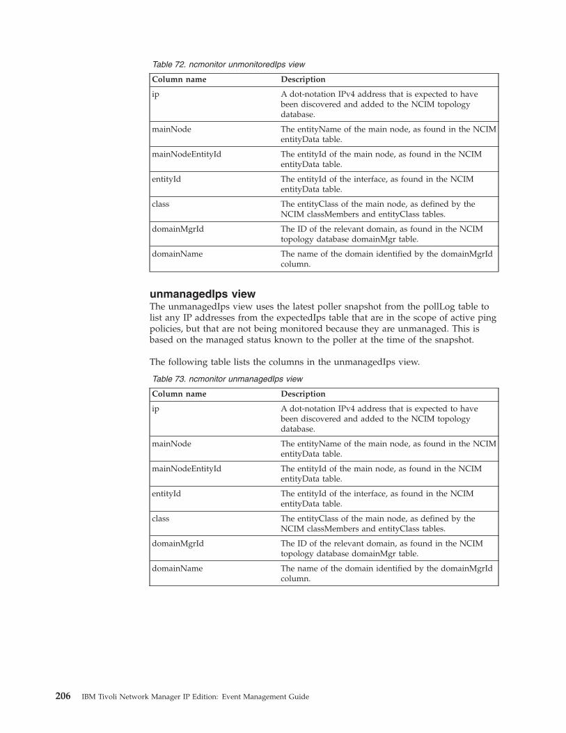
Table 72. ncmonitor unmonitoredIps view
Column name Description
ip A dot-notation IPv4 address that is expected to havebeen discovered and added to the NCIM topologydatabase.
mainNode The entityName of the main node, as found in the NCIMentityData table.
mainNodeEntityId The entityId of the main node, as found in the NCIMentityData table.
entityId The entityId of the interface, as found in the NCIMentityData table.
class The entityClass of the main node, as defined by theNCIM classMembers and entityClass tables.
domainMgrId The ID of the relevant domain, as found in the NCIMtopology database domainMgr table.
domainName The name of the domain identified by the domainMgrIdcolumn.
unmanagedIps viewThe unmanagedIps view uses the latest poller snapshot from the pollLog table tolist any IP addresses from the expectedIps table that are in the scope of active pingpolicies, but that are not being monitored because they are unmanaged. This isbased on the managed status known to the poller at the time of the snapshot.
The following table lists the columns in the unmanagedIps view.
Table 73. ncmonitor unmanagedIps view
Column name Description
ip A dot-notation IPv4 address that is expected to havebeen discovered and added to the NCIM topologydatabase.
mainNode The entityName of the main node, as found in the NCIMentityData table.
mainNodeEntityId The entityId of the main node, as found in the NCIMentityData table.
entityId The entityId of the interface, as found in the NCIMentityData table.
class The entityClass of the main node, as defined by theNCIM classMembers and entityClass tables.
domainMgrId The ID of the relevant domain, as found in the NCIMtopology database domainMgr table.
domainName The name of the domain identified by the domainMgrIdcolumn.
206 IBM Tivoli Network Manager IP Edition: Event Management Guide
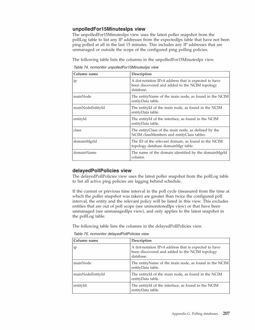
unpolledFor15MinutesIps viewThe unpolledFor15MinutesIps view uses the latest poller snapshot from thepollLog table to list any IP addresses from the expectedIps table that have not beenping polled at all in the last 15 minutes. This includes any IP addresses that areunmanaged or outside the scope of the configured ping polling policies.
The following table lists the columns in the unpolledFor15MinutesIps view.
Table 74. ncmonitor unpolledFor15MinutesIps view
Column name Description
ip A dot-notation IPv4 address that is expected to havebeen discovered and added to the NCIM topologydatabase.
mainNode The entityName of the main node, as found in the NCIMentityData table.
mainNodeEntityId The entityId of the main node, as found in the NCIMentityData table.
entityId The entityId of the interface, as found in the NCIMentityData table.
class The entityClass of the main node, as defined by theNCIM classMembers and entityClass tables.
domainMgrId The ID of the relevant domain, as found in the NCIMtopology database domainMgr table.
domainName The name of the domain identified by the domainMgrIdcolumn.
delayedPollPolicies viewThe delayedPollPolicies view uses the latest poller snapshot from the pollLog tableto list all active ping policies are lagging behind schedule.
If the current or previous time interval in the poll cycle (measured from the time atwhich the poller snapshot was taken) are greater than twice the configured pollinterval, the entity and the relevant policy will be listed in this view. This excludesentities that are out of poll scope (see unmonitoredIps view) or that have beenunmanaged (see unmanagedIps view), and only applies to the latest snapshot inthe pollLog table.
The following table lists the columns in the delayedPollPolicies view.
Table 75. ncmonitor delayedPollPolicies view
Column name Description
ip A dot-notation IPv4 address that is expected to havebeen discovered and added to the NCIM topologydatabase.
mainNode The entityName of the main node, as found in the NCIMentityData table.
mainNodeEntityId The entityId of the main node, as found in the NCIMentityData table.
entityId The entityId of the interface, as found in the NCIMentityData table.
Appendix G. Polling databases 207
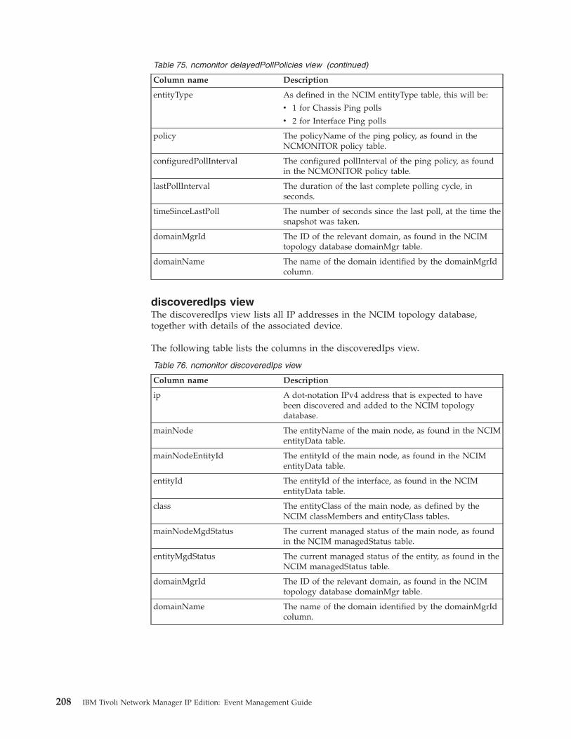
Table 75. ncmonitor delayedPollPolicies view (continued)
Column name Description
entityType As defined in the NCIM entityType table, this will be:
v 1 for Chassis Ping polls
v 2 for Interface Ping polls
policy The policyName of the ping policy, as found in theNCMONITOR policy table.
configuredPollInterval The configured pollInterval of the ping policy, as foundin the NCMONITOR policy table.
lastPollInterval The duration of the last complete polling cycle, inseconds.
timeSinceLastPoll The number of seconds since the last poll, at the time thesnapshot was taken.
domainMgrId The ID of the relevant domain, as found in the NCIMtopology database domainMgr table.
domainName The name of the domain identified by the domainMgrIdcolumn.
discoveredIps viewThe discoveredIps view lists all IP addresses in the NCIM topology database,together with details of the associated device.
The following table lists the columns in the discoveredIps view.
Table 76. ncmonitor discoveredIps view
Column name Description
ip A dot-notation IPv4 address that is expected to havebeen discovered and added to the NCIM topologydatabase.
mainNode The entityName of the main node, as found in the NCIMentityData table.
mainNodeEntityId The entityId of the main node, as found in the NCIMentityData table.
entityId The entityId of the interface, as found in the NCIMentityData table.
class The entityClass of the main node, as defined by theNCIM classMembers and entityClass tables.
mainNodeMgdStatus The current managed status of the main node, as foundin the NCIM managedStatus table.
entityMgdStatus The current managed status of the entity, as found in theNCIM managedStatus table.
domainMgrId The ID of the relevant domain, as found in the NCIMtopology database domainMgr table.
domainName The name of the domain identified by the domainMgrIdcolumn.
208 IBM Tivoli Network Manager IP Edition: Event Management Guide
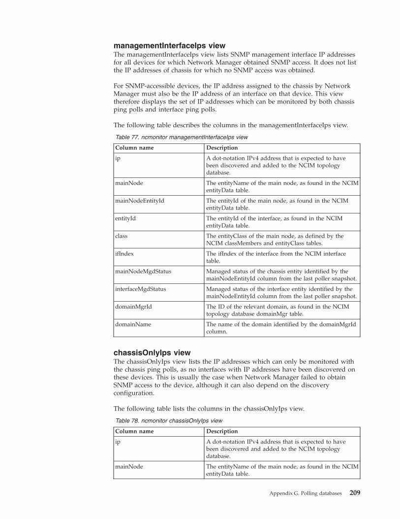
managementInterfaceIps viewThe managementInterfaceIps view lists SNMP management interface IP addressesfor all devices for which Network Manager obtained SNMP access. It does not listthe IP addresses of chassis for which no SNMP access was obtained.
For SNMP-accessible devices, the IP address assigned to the chassis by NetworkManager must also be the IP address of an interface on that device. This viewtherefore displays the set of IP addresses which can be monitored by both chassisping polls and interface ping polls.
The following table describes the columns in the managementInterfaceIps view.
Table 77. ncmonitor managementInterfaceIps view
Column name Description
ip A dot-notation IPv4 address that is expected to havebeen discovered and added to the NCIM topologydatabase.
mainNode The entityName of the main node, as found in the NCIMentityData table.
mainNodeEntityId The entityId of the main node, as found in the NCIMentityData table.
entityId The entityId of the interface, as found in the NCIMentityData table.
class The entityClass of the main node, as defined by theNCIM classMembers and entityClass tables.
ifIndex The ifIndex of the interface from the NCIM interfacetable.
mainNodeMgdStatus Managed status of the chassis entity identified by themainNodeEntityId column from the last poller snapshot.
interfaceMgdStatus Managed status of the interface entity identified by themainNodeEntityId column from the last poller snapshot.
domainMgrId The ID of the relevant domain, as found in the NCIMtopology database domainMgr table.
domainName The name of the domain identified by the domainMgrIdcolumn.
chassisOnlyIps viewThe chassisOnlyIps view lists the IP addresses which can only be monitored withthe chassis ping polls, as no interfaces with IP addresses have been discovered onthese devices. This is usually the case when Network Manager failed to obtainSNMP access to the device, although it can also depend on the discoveryconfiguration.
The following table lists the columns in the chassisOnlyIps view.
Table 78. ncmonitor chassisOnlyIps view
Column name Description
ip A dot-notation IPv4 address that is expected to havebeen discovered and added to the NCIM topologydatabase.
mainNode The entityName of the main node, as found in the NCIMentityData table.
Appendix G. Polling databases 209
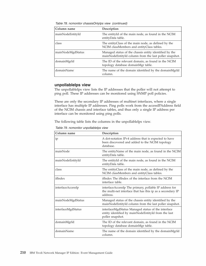
Table 78. ncmonitor chassisOnlyIps view (continued)
Column name Description
mainNodeEntityId The entityId of the main node, as found in the NCIMentityData table.
class The entityClass of the main node, as defined by theNCIM classMembers and entityClass tables.
mainNodeMgdStatus Managed status of the chassis entity identified by themainNodeEntityId column from the last poller snapshot.
domainMgrId The ID of the relevant domain, as found in the NCIMtopology database domainMgr table.
domainName The name of the domain identified by the domainMgrIdcolumn.
unpollableIps viewThe unpollableIps view lists the IP addresses that the poller will not attempt toping poll. These IP addresses can be monitored using SNMP poll policies.
These are only the secondary IP addresses of multinet interfaces, where a singleinterface has multiple IP addresses. Ping polls work from the accessIPAddress fieldof the NCIM chassis and interface tables, and thus only a single IP address perinterface can be monitored using ping polls.
The following table lists the columns in the unpollableIps view.
Table 79. ncmonitor unpollableIps view
Column name Description
ip A dot-notation IPv4 address that is expected to havebeen discovered and added to the NCIM topologydatabase.
mainNode The entityName of the main node, as found in the NCIMentityData table.
mainNodeEntityId The entityId of the main node, as found in the NCIMentityData table.
class The entityClass of the main node, as defined by theNCIM classMembers and entityClass tables.
ifIndex ifIndex The ifIndex of the interface from the NCIMinterface table.
interfaceAccessIp interfaceAccessIp The primary, pollable IP address forthe multi-net interface that has this ip as a secondary IPaddress.
mainNodeMgdStatus Managed status of the chassis entity identified by themainNodeEntityId column from the last poller snapshot.
interfaceMgdStatus interfaceMgdStatus Managed status of the interfaceentity identified by mainNodeEntityId from the lastpoller snapshot.
domainMgrId The ID of the relevant domain, as found in the NCIMtopology database domainMgr table.
domainName The name of the domain identified by the domainMgrIdcolumn.
210 IBM Tivoli Network Manager IP Edition: Event Management Guide
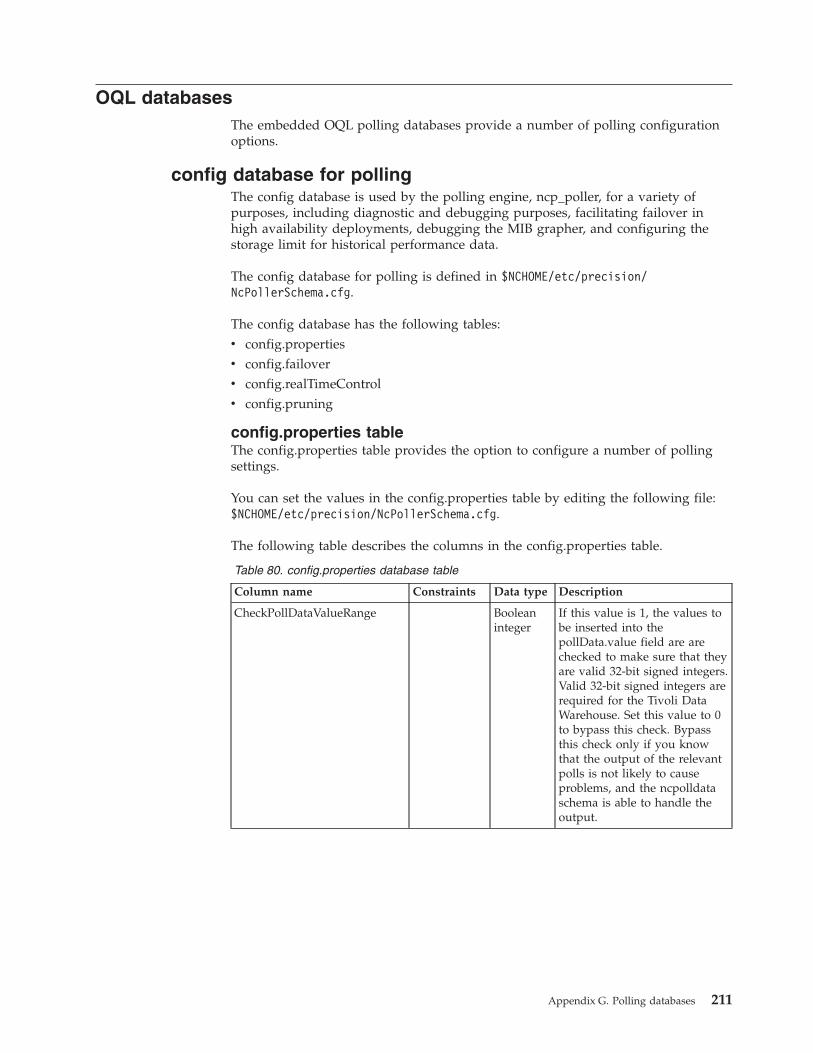
OQL databasesThe embedded OQL polling databases provide a number of polling configurationoptions.
config database for pollingThe config database is used by the polling engine, ncp_poller, for a variety ofpurposes, including diagnostic and debugging purposes, facilitating failover inhigh availability deployments, debugging the MIB grapher, and configuring thestorage limit for historical performance data.
The config database for polling is defined in $NCHOME/etc/precision/NcPollerSchema.cfg.
The config database has the following tables:v config.propertiesv config.failoverv config.realTimeControlv config.pruning
config.properties tableThe config.properties table provides the option to configure a number of pollingsettings.
You can set the values in the config.properties table by editing the following file:$NCHOME/etc/precision/NcPollerSchema.cfg.
The following table describes the columns in the config.properties table.
Table 80. config.properties database table
Column name Constraints Data type Description
CheckPollDataValueRange Booleaninteger
If this value is 1, the values tobe inserted into thepollData.value field are arechecked to make sure that theyare valid 32-bit signed integers.Valid 32-bit signed integers arerequired for the Tivoli DataWarehouse. Set this value to 0to bypass this check. Bypassthis check only if you knowthat the output of the relevantpolls is not likely to causeproblems, and the ncpolldataschema is able to handle theoutput.
Appendix G. Polling databases 211
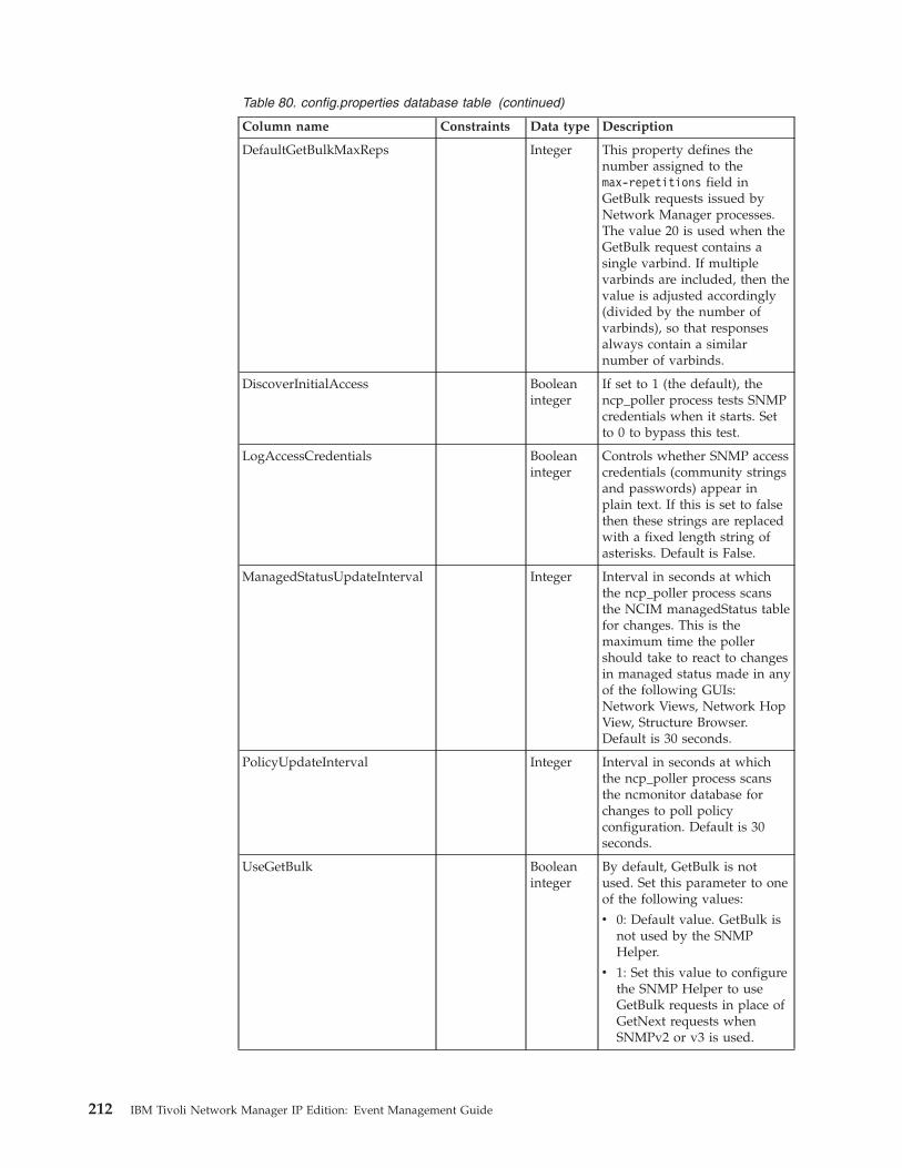
Table 80. config.properties database table (continued)
Column name Constraints Data type Description
DefaultGetBulkMaxReps Integer This property defines thenumber assigned to themax-repetitions field inGetBulk requests issued byNetwork Manager processes.The value 20 is used when theGetBulk request contains asingle varbind. If multiplevarbinds are included, then thevalue is adjusted accordingly(divided by the number ofvarbinds), so that responsesalways contain a similarnumber of varbinds.
DiscoverInitialAccess Booleaninteger
If set to 1 (the default), thencp_poller process tests SNMPcredentials when it starts. Setto 0 to bypass this test.
LogAccessCredentials Booleaninteger
Controls whether SNMP accesscredentials (community stringsand passwords) appear inplain text. If this is set to falsethen these strings are replacedwith a fixed length string ofasterisks. Default is False.
ManagedStatusUpdateInterval Integer Interval in seconds at whichthe ncp_poller process scansthe NCIM managedStatus tablefor changes. This is themaximum time the pollershould take to react to changesin managed status made in anyof the following GUIs:Network Views, Network HopView, Structure Browser.Default is 30 seconds.
PolicyUpdateInterval Integer Interval in seconds at whichthe ncp_poller process scansthe ncmonitor database forchanges to poll policyconfiguration. Default is 30seconds.
UseGetBulk Booleaninteger
By default, GetBulk is notused. Set this parameter to oneof the following values:
v 0: Default value. GetBulk isnot used by the SNMPHelper.
v 1: Set this value to configurethe SNMP Helper to useGetBulk requests in place ofGetNext requests whenSNMPv2 or v3 is used.
212 IBM Tivoli Network Manager IP Edition: Event Management Guide
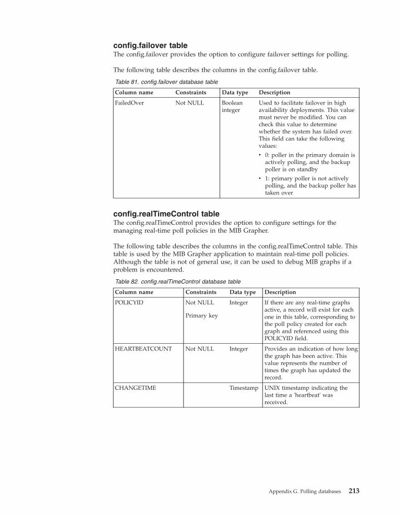
config.failover tableThe config.failover provides the option to configure failover settings for polling.
The following table describes the columns in the config.failover table.
Table 81. config.failover database table
Column name Constraints Data type Description
FailedOver Not NULL Booleaninteger
Used to facilitate failover in highavailability deployments. This valuemust never be modified. You cancheck this value to determinewhether the system has failed over.This field can take the followingvalues:
v 0: poller in the primary domain isactively polling, and the backuppoller is on standby
v 1: primary poller is not activelypolling, and the backup poller hastaken over
config.realTimeControl tableThe config.realTimeControl provides the option to configure settings for themanaging real-time poll policies in the MIB Grapher.
The following table describes the columns in the config.realTimeControl table. Thistable is used by the MIB Grapher application to maintain real-time poll policies.Although the table is not of general use, it can be used to debug MIB graphs if aproblem is encountered.
Table 82. config.realTimeControl database table
Column name Constraints Data type Description
POLICYID Not NULL
Primary key
Integer If there are any real-time graphsactive, a record will exist for eachone in this table, corresponding tothe poll policy created for eachgraph and referenced using thisPOLICYID field.
HEARTBEATCOUNT Not NULL Integer Provides an indication of how longthe graph has been active. Thisvalue represents the number oftimes the graph has updated therecord.
CHANGETIME Timestamp UNIX timestamp indicating thelast time a 'heartbeat' wasreceived.
Appendix G. Polling databases 213
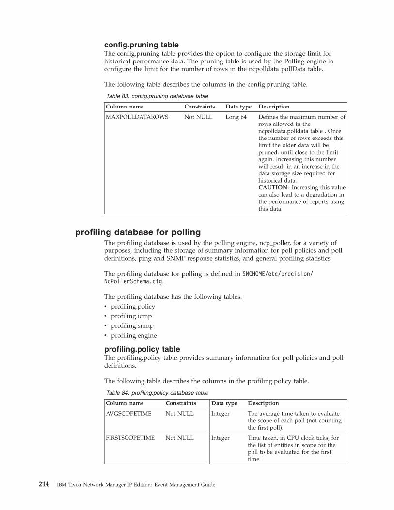
config.pruning tableThe config.pruning table provides the option to configure the storage limit forhistorical performance data. The pruning table is used by the Polling engine toconfigure the limit for the number of rows in the ncpolldata pollData table.
The following table describes the columns in the config.pruning table.
Table 83. config.pruning database table
Column name Constraints Data type Description
MAXPOLLDATAROWS Not NULL Long 64 Defines the maximum number ofrows allowed in thencpolldata.polldata table . Oncethe number of rows exceeds thislimit the older data will bepruned, until close to the limitagain. Increasing this numberwill result in an increase in thedata storage size required forhistorical data.CAUTION: Increasing this valuecan also lead to a degradation inthe performance of reports usingthis data.
profiling database for pollingThe profiling database is used by the polling engine, ncp_poller, for a variety ofpurposes, including the storage of summary information for poll policies and polldefinitions, ping and SNMP response statistics, and general profiling statistics.
The profiling database for polling is defined in $NCHOME/etc/precision/NcPollerSchema.cfg.
The profiling database has the following tables:v profiling.policyv profiling.icmpv profiling.snmpv profiling.engine
profiling.policy tableThe profiling.policy table provides summary information for poll policies and polldefinitions.
The following table describes the columns in the profiling.policy table.
Table 84. profiling.policy database table
Column name Constraints Data type Description
AVGSCOPETIME Not NULL Integer The average time taken to evaluatethe scope of each poll (not countingthe first poll).
FIRSTSCOPETIME Not NULL Integer Time taken, in CPU clock ticks, forthe list of entities in scope for thepoll to be evaluated for the firsttime.
214 IBM Tivoli Network Manager IP Edition: Event Management Guide
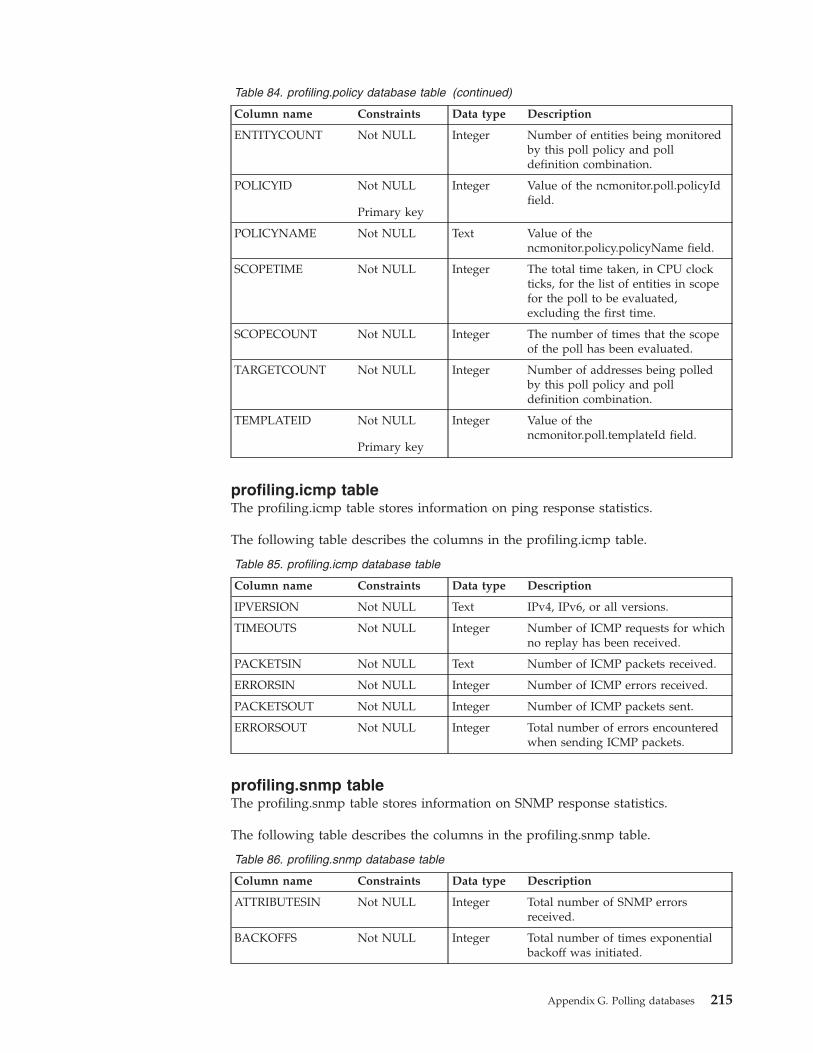
Table 84. profiling.policy database table (continued)
Column name Constraints Data type Description
ENTITYCOUNT Not NULL Integer Number of entities being monitoredby this poll policy and polldefinition combination.
POLICYID Not NULL
Primary key
Integer Value of the ncmonitor.poll.policyIdfield.
POLICYNAME Not NULL Text Value of thencmonitor.policy.policyName field.
SCOPETIME Not NULL Integer The total time taken, in CPU clockticks, for the list of entities in scopefor the poll to be evaluated,excluding the first time.
SCOPECOUNT Not NULL Integer The number of times that the scopeof the poll has been evaluated.
TARGETCOUNT Not NULL Integer Number of addresses being polledby this poll policy and polldefinition combination.
TEMPLATEID Not NULL
Primary key
Integer Value of thencmonitor.poll.templateId field.
profiling.icmp tableThe profiling.icmp table stores information on ping response statistics.
The following table describes the columns in the profiling.icmp table.
Table 85. profiling.icmp database table
Column name Constraints Data type Description
IPVERSION Not NULL Text IPv4, IPv6, or all versions.
TIMEOUTS Not NULL Integer Number of ICMP requests for whichno replay has been received.
PACKETSIN Not NULL Text Number of ICMP packets received.
ERRORSIN Not NULL Integer Number of ICMP errors received.
PACKETSOUT Not NULL Integer Number of ICMP packets sent.
ERRORSOUT Not NULL Integer Total number of errors encounteredwhen sending ICMP packets.
profiling.snmp tableThe profiling.snmp table stores information on SNMP response statistics.
The following table describes the columns in the profiling.snmp table.
Table 86. profiling.snmp database table
Column name Constraints Data type Description
ATTRIBUTESIN Not NULL Integer Total number of SNMP errorsreceived.
BACKOFFS Not NULL Integer Total number of times exponentialbackoff was initiated.
Appendix G. Polling databases 215
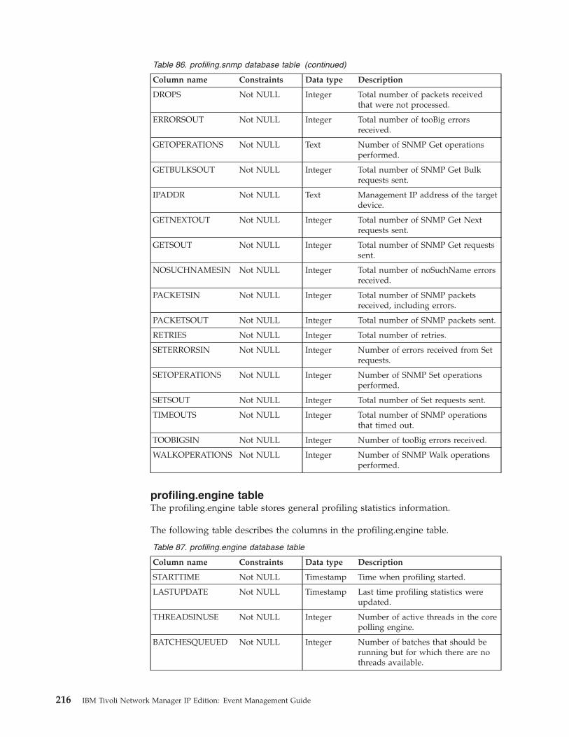
Table 86. profiling.snmp database table (continued)
Column name Constraints Data type Description
DROPS Not NULL Integer Total number of packets receivedthat were not processed.
ERRORSOUT Not NULL Integer Total number of tooBig errorsreceived.
GETOPERATIONS Not NULL Text Number of SNMP Get operationsperformed.
GETBULKSOUT Not NULL Integer Total number of SNMP Get Bulkrequests sent.
IPADDR Not NULL Text Management IP address of the targetdevice.
GETNEXTOUT Not NULL Integer Total number of SNMP Get Nextrequests sent.
GETSOUT Not NULL Integer Total number of SNMP Get requestssent.
NOSUCHNAMESIN Not NULL Integer Total number of noSuchName errorsreceived.
PACKETSIN Not NULL Integer Total number of SNMP packetsreceived, including errors.
PACKETSOUT Not NULL Integer Total number of SNMP packets sent.
RETRIES Not NULL Integer Total number of retries.
SETERRORSIN Not NULL Integer Number of errors received from Setrequests.
SETOPERATIONS Not NULL Integer Number of SNMP Set operationsperformed.
SETSOUT Not NULL Integer Total number of Set requests sent.
TIMEOUTS Not NULL Integer Total number of SNMP operationsthat timed out.
TOOBIGSIN Not NULL Integer Number of tooBig errors received.
WALKOPERATIONS Not NULL Integer Number of SNMP Walk operationsperformed.
profiling.engine tableThe profiling.engine table stores general profiling statistics information.
The following table describes the columns in the profiling.engine table.
Table 87. profiling.engine database table
Column name Constraints Data type Description
STARTTIME Not NULL Timestamp Time when profiling started.
LASTUPDATE Not NULL Timestamp Last time profiling statistics wereupdated.
THREADSINUSE Not NULL Integer Number of active threads in the corepolling engine.
BATCHESQUEUED Not NULL Integer Number of batches that should berunning but for which there are nothreads available.
216 IBM Tivoli Network Manager IP Edition: Event Management Guide

Table 87. profiling.engine database table (continued)
Column name Constraints Data type Description
AVGBATCHTIME Not NULL Integer Average time in milliseconds toprocess each batch of work.
Appendix G. Polling databases 217

218 IBM Tivoli Network Manager IP Edition: Event Management Guide
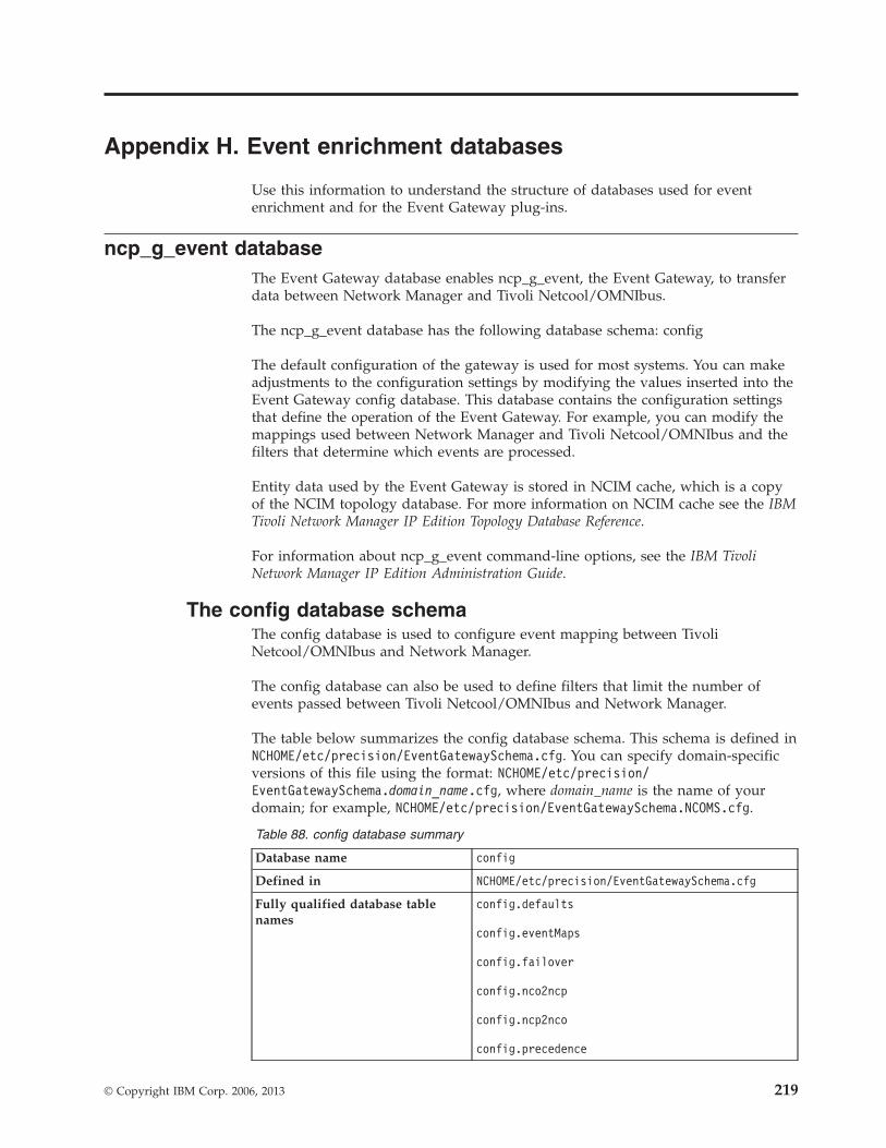
Appendix H. Event enrichment databases
Use this information to understand the structure of databases used for eventenrichment and for the Event Gateway plug-ins.
ncp_g_event databaseThe Event Gateway database enables ncp_g_event, the Event Gateway, to transferdata between Network Manager and Tivoli Netcool/OMNIbus.
The ncp_g_event database has the following database schema: config
The default configuration of the gateway is used for most systems. You can makeadjustments to the configuration settings by modifying the values inserted into theEvent Gateway config database. This database contains the configuration settingsthat define the operation of the Event Gateway. For example, you can modify themappings used between Network Manager and Tivoli Netcool/OMNIbus and thefilters that determine which events are processed.
Entity data used by the Event Gateway is stored in NCIM cache, which is a copyof the NCIM topology database. For more information on NCIM cache see the IBMTivoli Network Manager IP Edition Topology Database Reference.
For information about ncp_g_event command-line options, see the IBM TivoliNetwork Manager IP Edition Administration Guide.
The config database schemaThe config database is used to configure event mapping between TivoliNetcool/OMNIbus and Network Manager.
The config database can also be used to define filters that limit the number ofevents passed between Tivoli Netcool/OMNIbus and Network Manager.
The table below summarizes the config database schema. This schema is defined inNCHOME/etc/precision/EventGatewaySchema.cfg. You can specify domain-specificversions of this file using the format: NCHOME/etc/precision/EventGatewaySchema.domain_name.cfg, where domain_name is the name of yourdomain; for example, NCHOME/etc/precision/EventGatewaySchema.NCOMS.cfg.
Table 88. config database summary
Database name config
Defined in NCHOME/etc/precision/EventGatewaySchema.cfg
Fully qualified database tablenames
config.defaults
config.eventMaps
config.failover
config.nco2ncp
config.ncp2nco
config.precedence
© Copyright IBM Corp. 2006, 2013 219
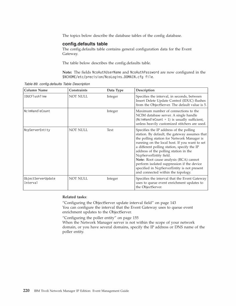
The topics below describe the database tables of the config database.
config.defaults tableThe config.defaults table contains general configuration data for the EventGateway.
The table below describes the config.defaults table.
Note: The fields NcoAuthUserName and NcoAuthPassword are now configured in the$NCHOME/etc/precision/NcoLogins.DOMAIN.cfg file.
Table 89. config.defaults Table Description
Column Name Constraints Data Type Description
IDUCFlushTime NOT NULL Integer Specifies the interval, in seconds, betweenInsert Delete Update Control (IDUC) flushesfrom the ObjectServer. The default value is 5.
NcimHandleCount Integer Maximum number of connections to theNCIM database server. A single handle(NcimHandleCount = 1) is usually sufficient,unless heavily customized stitchers are used.
NcpServerEntity NOT NULL Text Specifies the IP address of the pollingstation. By default, the gateway assumes thatthe polling station for Network Manager isrunning on the local host. If you want to seta different polling station, specify the IPaddress of the polling station in theNcpServerEntity field.Note: Root cause analysis (RCA) cannotperform isolated suppression if the devicespecified in NcpServerEntity is not presentand connected within the topology.
ObjectServerUpdateInterval
NOT NULL Integer Specifies the interval that the Event Gatewayuses to queue event enrichment updates tothe ObjectServer.
Related tasks:“Configuring the ObjectServer update interval field” on page 143You can configure the interval that the Event Gateway uses to queue eventenrichment updates to the ObjectServer.“Configuring the poller entity” on page 155When the Network Manager server is not within the scope of your networkdomain, or you have several domains, specify the IP address or DNS name of thepoller entity.
220 IBM Tivoli Network Manager IP Edition: Event Management Guide
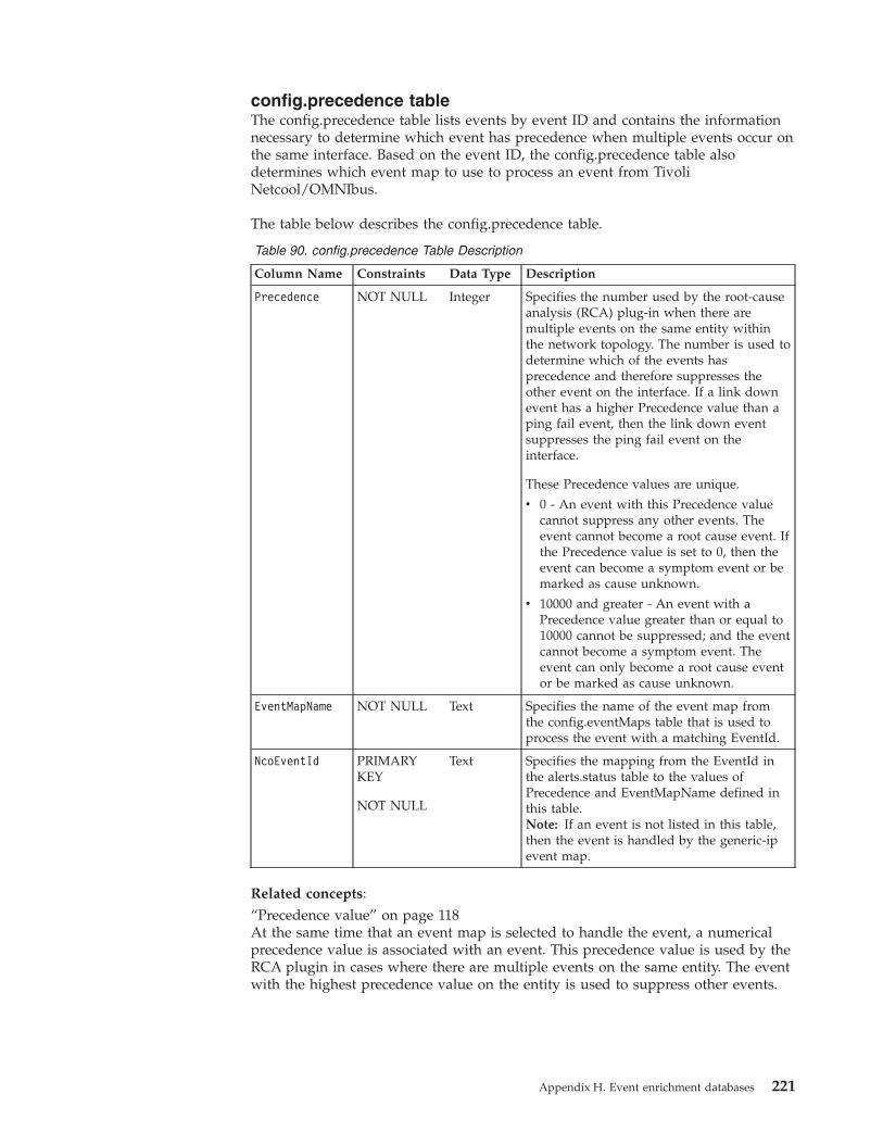
config.precedence tableThe config.precedence table lists events by event ID and contains the informationnecessary to determine which event has precedence when multiple events occur onthe same interface. Based on the event ID, the config.precedence table alsodetermines which event map to use to process an event from TivoliNetcool/OMNIbus.
The table below describes the config.precedence table.
Table 90. config.precedence Table Description
Column Name Constraints Data Type Description
Precedence NOT NULL Integer Specifies the number used by the root-causeanalysis (RCA) plug-in when there aremultiple events on the same entity withinthe network topology. The number is used todetermine which of the events hasprecedence and therefore suppresses theother event on the interface. If a link downevent has a higher Precedence value than aping fail event, then the link down eventsuppresses the ping fail event on theinterface.
These Precedence values are unique.
v 0 - An event with this Precedence valuecannot suppress any other events. Theevent cannot become a root cause event. Ifthe Precedence value is set to 0, then theevent can become a symptom event or bemarked as cause unknown.
v 10000 and greater - An event with aPrecedence value greater than or equal to10000 cannot be suppressed; and the eventcannot become a symptom event. Theevent can only become a root cause eventor be marked as cause unknown.
EventMapName NOT NULL Text Specifies the name of the event map fromthe config.eventMaps table that is used toprocess the event with a matching EventId.
NcoEventId PRIMARYKEY
NOT NULL
Text Specifies the mapping from the EventId inthe alerts.status table to the values ofPrecedence and EventMapName defined inthis table.Note: If an event is not listed in this table,then the event is handled by the generic-ipevent map.
Related concepts:“Precedence value” on page 118At the same time that an event map is selected to handle the event, a numericalprecedence value is associated with an event. This precedence value is used by theRCA plugin in cases where there are multiple events on the same entity. The eventwith the highest precedence value on the entity is used to suppress other events.
Appendix H. Event enrichment databases 221
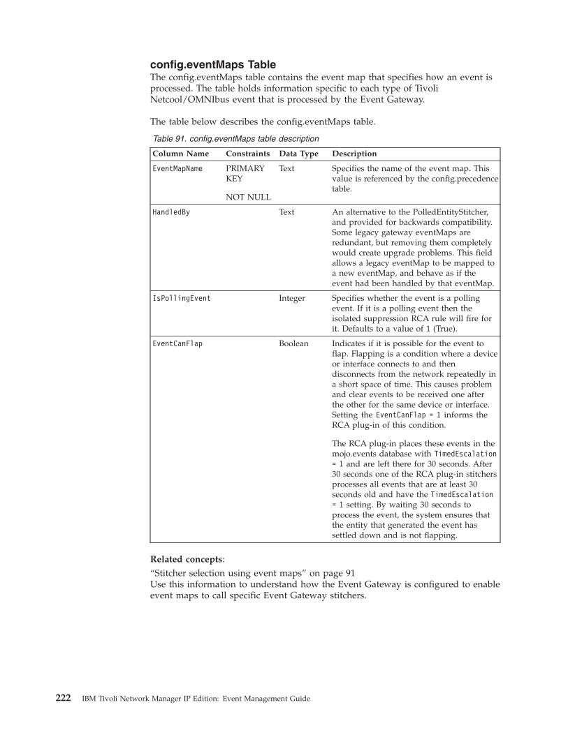
config.eventMaps TableThe config.eventMaps table contains the event map that specifies how an event isprocessed. The table holds information specific to each type of TivoliNetcool/OMNIbus event that is processed by the Event Gateway.
The table below describes the config.eventMaps table.
Table 91. config.eventMaps table description
Column Name Constraints Data Type Description
EventMapName PRIMARYKEY
NOT NULL
Text Specifies the name of the event map. Thisvalue is referenced by the config.precedencetable.
HandledBy Text An alternative to the PolledEntityStitcher,and provided for backwards compatibility.Some legacy gateway eventMaps areredundant, but removing them completelywould create upgrade problems. This fieldallows a legacy eventMap to be mapped toa new eventMap, and behave as if theevent had been handled by that eventMap.
IsPollingEvent Integer Specifies whether the event is a pollingevent. If it is a polling event then theisolated suppression RCA rule will fire forit. Defaults to a value of 1 (True).
EventCanFlap Boolean Indicates if it is possible for the event toflap. Flapping is a condition where a deviceor interface connects to and thendisconnects from the network repeatedly ina short space of time. This causes problemand clear events to be received one afterthe other for the same device or interface.Setting the EventCanFlap = 1 informs theRCA plug-in of this condition.
The RCA plug-in places these events in themojo.events database with TimedEscalation= 1 and are left there for 30 seconds. After30 seconds one of the RCA plug-in stitchersprocesses all events that are at least 30seconds old and have the TimedEscalation= 1 setting. By waiting 30 seconds toprocess the event, the system ensures thatthe entity that generated the event hassettled down and is not flapping.
Related concepts:“Stitcher selection using event maps” on page 91Use this information to understand how the Event Gateway is configured to enableevent maps to call specific Event Gateway stitchers.
222 IBM Tivoli Network Manager IP Edition: Event Management Guide
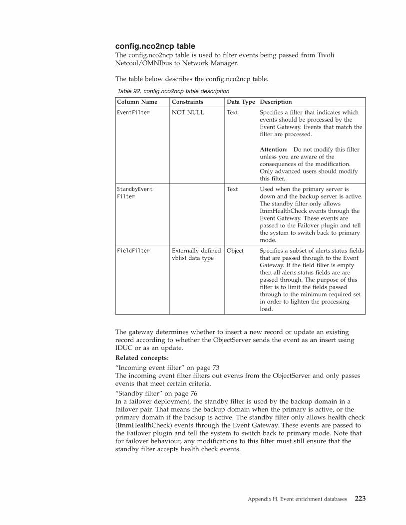
config.nco2ncp tableThe config.nco2ncp table is used to filter events being passed from TivoliNetcool/OMNIbus to Network Manager.
The table below describes the config.nco2ncp table.
Table 92. config.nco2ncp table description
Column Name Constraints Data Type Description
EventFilter NOT NULL Text Specifies a filter that indicates whichevents should be processed by theEvent Gateway. Events that match thefilter are processed.
Attention: Do not modify this filterunless you are aware of theconsequences of the modification.Only advanced users should modifythis filter.
StandbyEventFilter
Text Used when the primary server isdown and the backup server is active.The standby filter only allowsItnmHealthCheck events through theEvent Gateway. These events arepassed to the Failover plugin and tellthe system to switch back to primarymode.
FieldFilter Externally definedvblist data type
Object Specifies a subset of alerts.status fieldsthat are passed through to the EventGateway. If the field filter is emptythen all alerts.status fields are arepassed through. The purpose of thisfilter is to limit the fields passedthrough to the minimum required setin order to lighten the processingload.
The gateway determines whether to insert a new record or update an existingrecord according to whether the ObjectServer sends the event as an insert usingIDUC or as an update.Related concepts:“Incoming event filter” on page 73The incoming event filter filters out events from the ObjectServer and only passesevents that meet certain criteria.“Standby filter” on page 76In a failover deployment, the standby filter is used by the backup domain in afailover pair. That means the backup domain when the primary is active, or theprimary domain if the backup is active. The standby filter only allows health check(ItnmHealthCheck) events through the Event Gateway. These events are passed tothe Failover plugin and tell the system to switch back to primary mode. Note thatfor failover behaviour, any modifications to this filter must still ensure that thestandby filter accepts health check events.
Appendix H. Event enrichment databases 223
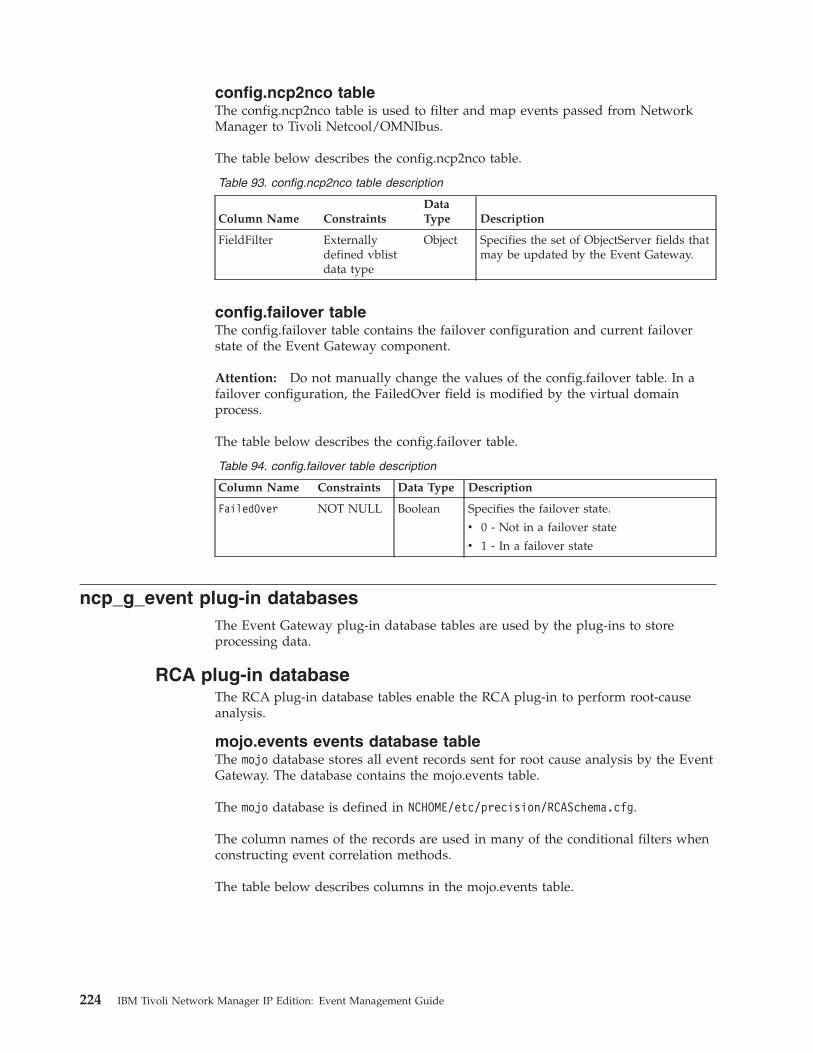
config.ncp2nco tableThe config.ncp2nco table is used to filter and map events passed from NetworkManager to Tivoli Netcool/OMNIbus.
The table below describes the config.ncp2nco table.
Table 93. config.ncp2nco table description
Column Name ConstraintsDataType Description
FieldFilter Externallydefined vblistdata type
Object Specifies the set of ObjectServer fields thatmay be updated by the Event Gateway.
config.failover tableThe config.failover table contains the failover configuration and current failoverstate of the Event Gateway component.
Attention: Do not manually change the values of the config.failover table. In afailover configuration, the FailedOver field is modified by the virtual domainprocess.
The table below describes the config.failover table.
Table 94. config.failover table description
Column Name Constraints Data Type Description
FailedOver NOT NULL Boolean Specifies the failover state.
v 0 - Not in a failover state
v 1 - In a failover state
ncp_g_event plug-in databasesThe Event Gateway plug-in database tables are used by the plug-ins to storeprocessing data.
RCA plug-in databaseThe RCA plug-in database tables enable the RCA plug-in to perform root-causeanalysis.
mojo.events events database tableThe mojo database stores all event records sent for root cause analysis by the EventGateway. The database contains the mojo.events table.
The mojo database is defined in NCHOME/etc/precision/RCASchema.cfg.
The column names of the records are used in many of the conditional filters whenconstructing event correlation methods.
The table below describes columns in the mojo.events table.
224 IBM Tivoli Network Manager IP Edition: Event Management Guide
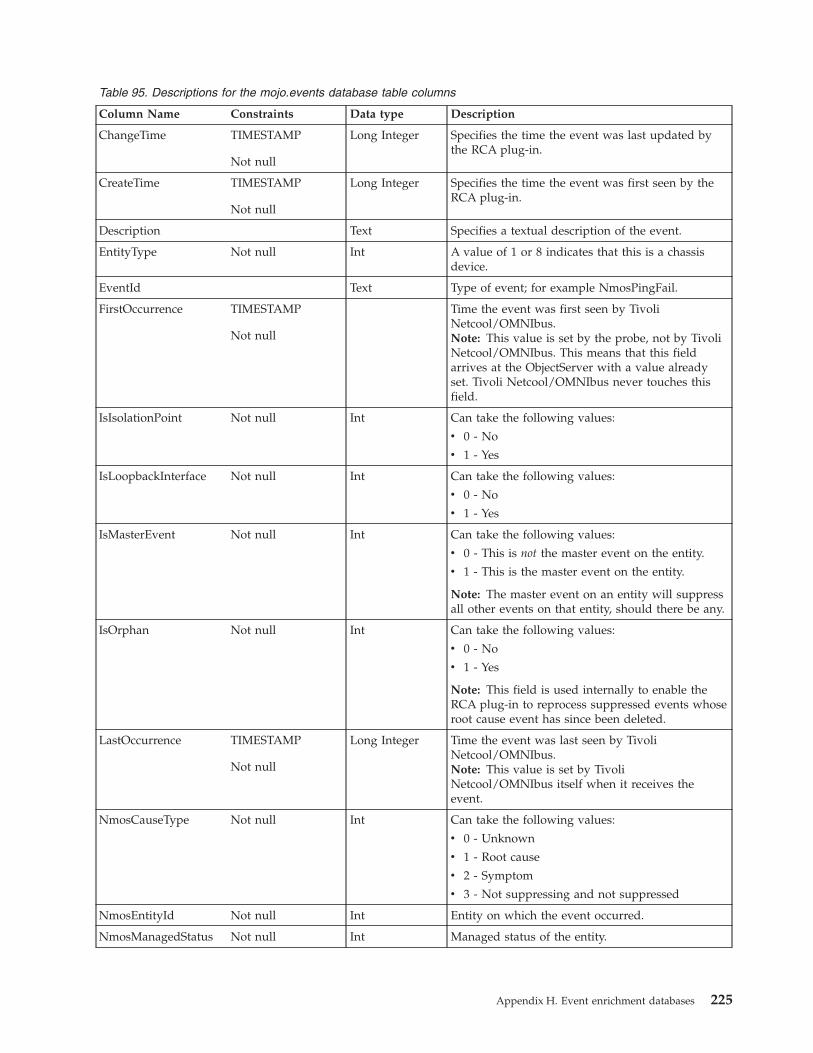
Table 95. Descriptions for the mojo.events database table columns
Column Name Constraints Data type Description
ChangeTime TIMESTAMP
Not null
Long Integer Specifies the time the event was last updated bythe RCA plug-in.
CreateTime TIMESTAMP
Not null
Long Integer Specifies the time the event was first seen by theRCA plug-in.
Description Text Specifies a textual description of the event.
EntityType Not null Int A value of 1 or 8 indicates that this is a chassisdevice.
EventId Text Type of event; for example NmosPingFail.
FirstOccurrence TIMESTAMP
Not null
Time the event was first seen by TivoliNetcool/OMNIbus.Note: This value is set by the probe, not by TivoliNetcool/OMNIbus. This means that this fieldarrives at the ObjectServer with a value alreadyset. Tivoli Netcool/OMNIbus never touches thisfield.
IsIsolationPoint Not null Int Can take the following values:
v 0 - No
v 1 - Yes
IsLoopbackInterface Not null Int Can take the following values:
v 0 - No
v 1 - Yes
IsMasterEvent Not null Int Can take the following values:
v 0 - This is not the master event on the entity.
v 1 - This is the master event on the entity.
Note: The master event on an entity will suppressall other events on that entity, should there be any.
IsOrphan Not null Int Can take the following values:
v 0 - No
v 1 - Yes
Note: This field is used internally to enable theRCA plug-in to reprocess suppressed events whoseroot cause event has since been deleted.
LastOccurrence TIMESTAMP
Not null
Long Integer Time the event was last seen by TivoliNetcool/OMNIbus.Note: This value is set by TivoliNetcool/OMNIbus itself when it receives theevent.
NmosCauseType Not null Int Can take the following values:
v 0 - Unknown
v 1 - Root cause
v 2 - Symptom
v 3 - Not suppressing and not suppressed
NmosEntityId Not null Int Entity on which the event occurred.
NmosManagedStatus Not null Int Managed status of the entity.
Appendix H. Event enrichment databases 225
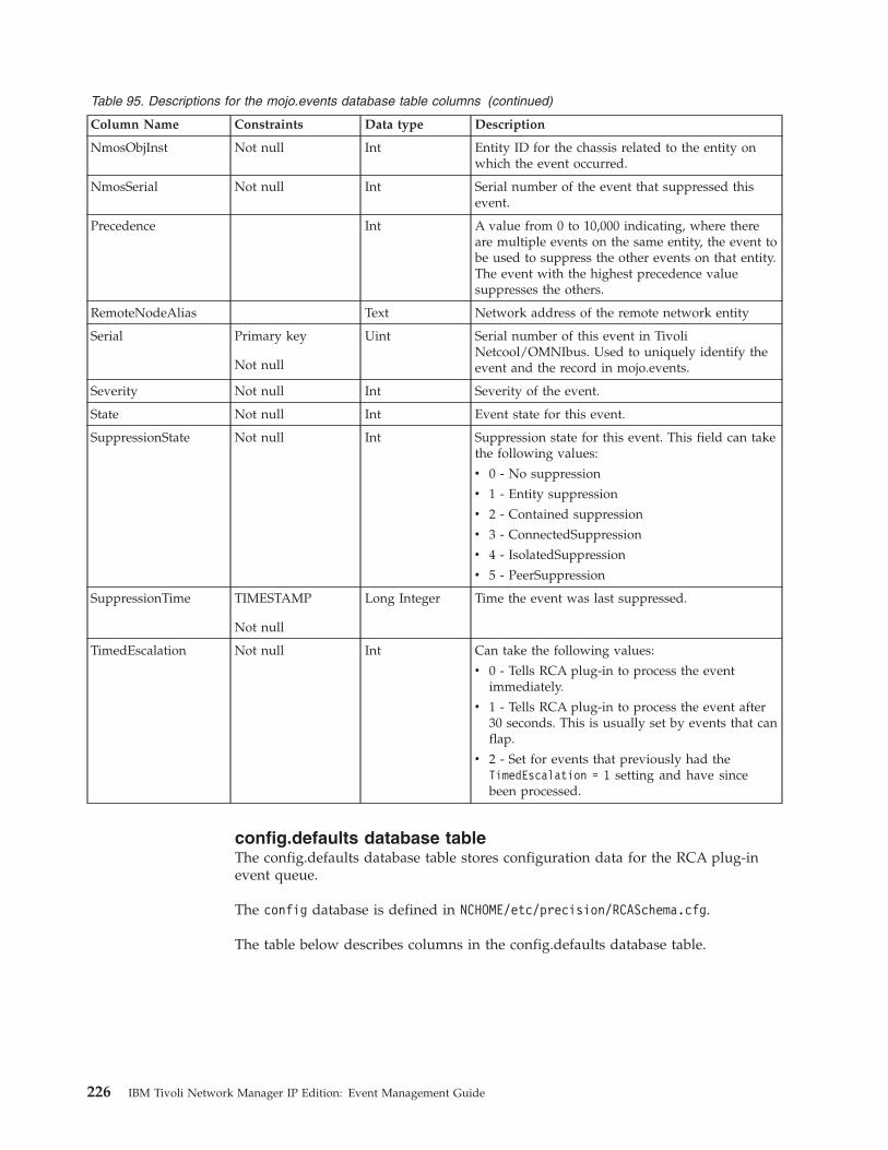
Table 95. Descriptions for the mojo.events database table columns (continued)
Column Name Constraints Data type Description
NmosObjInst Not null Int Entity ID for the chassis related to the entity onwhich the event occurred.
NmosSerial Not null Int Serial number of the event that suppressed thisevent.
Precedence Int A value from 0 to 10,000 indicating, where thereare multiple events on the same entity, the event tobe used to suppress the other events on that entity.The event with the highest precedence valuesuppresses the others.
RemoteNodeAlias Text Network address of the remote network entity
Serial Primary key
Not null
Uint Serial number of this event in TivoliNetcool/OMNIbus. Used to uniquely identify theevent and the record in mojo.events.
Severity Not null Int Severity of the event.
State Not null Int Event state for this event.
SuppressionState Not null Int Suppression state for this event. This field can takethe following values:
v 0 - No suppression
v 1 - Entity suppression
v 2 - Contained suppression
v 3 - ConnectedSuppression
v 4 - IsolatedSuppression
v 5 - PeerSuppression
SuppressionTime TIMESTAMP
Not null
Long Integer Time the event was last suppressed.
TimedEscalation Not null Int Can take the following values:
v 0 - Tells RCA plug-in to process the eventimmediately.
v 1 - Tells RCA plug-in to process the event after30 seconds. This is usually set by events that canflap.
v 2 - Set for events that previously had theTimedEscalation = 1 setting and have sincebeen processed.
config.defaults database tableThe config.defaults database table stores configuration data for the RCA plug-inevent queue.
The config database is defined in NCHOME/etc/precision/RCASchema.cfg.
The table below describes columns in the config.defaults database table.
226 IBM Tivoli Network Manager IP Edition: Event Management Guide
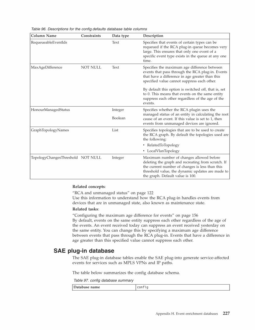
Table 96. Descriptions for the config.defaults database table columns
Column Name Constraints Data type Description
RequeueableEventIds Text Specifies that events of certain types can berequeued if the RCA plug-in queue becomes verylarge. This ensures that only one event of aspecific event type exists in the queue at any onetime.
MaxAgeDifference NOT NULL Text Specifies the maximum age difference betweenevents that pass through the RCA plug-in. Eventsthat have a difference in age greater than thisspecified value cannot suppress each other.
By default this option is switched off, that is, setto 0. This means that events on the same entitysuppress each other regardless of the age of theevents.
HonourManagedStatus Integer
Boolean
Specifies whether the RCA plugin uses themanaged status of an entity in calculating the rootcause of an event. If this value is set to 1, thenevents from unmanaged devices are ignored.
GraphTopologyNames List Specifies topologies that are to be used to createthe RCA graph. By default the topologies used arethe following:
v RelatedToTopology
v LocalVlanTopology
TopologyChangesThreshold NOT NULL Integer Maximum number of changes allowed beforedeleting the graph and recreating from scratch. Ifthe current number of changes is less than thisthreshold value, the dynamic updates are made tothe graph. Default value is 100.
Related concepts:“RCA and unmanaged status” on page 122Use this information to understand how the RCA plug-in handles events fromdevices that are in unmanaged state, also known as maintenance state.Related tasks:“Configuring the maximum age difference for events” on page 156By default, events on the same entity suppress each other regardless of the age ofthe events. An event received today can suppress an event received yesterday onthe same entity. You can change this by specifying a maximum age differencebetween events that pass through the RCA plug-in. Events that have a difference inage greater than this specified value cannot suppress each other.
SAE plug-in databaseThe SAE plug-in database tables enable the SAE plug-into generate service-affectedevents for services such as MPLS VPNs and IP paths.
The table below summarizes the config database schema.
Table 97. config database summary
Database name config
Appendix H. Event enrichment databases 227
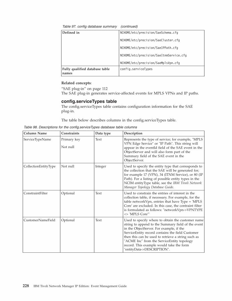
Table 97. config database summary (continued)
Defined in NCHOME/etc/precision/SaeSchema.cfg
NCHOME/etc/precision/SaeCluster.cfg
NCHOME/etc/precision/SaeIPPath.cfg
NCHOME/etc/precision/SaeItnmService.cfg
NCHOME/etc/precision/SaeMplsVpn.cfg
Fully qualified database tablenames
config.serviceTypes
Related concepts:“SAE plug-in” on page 112The SAE plug-in generates service-affected events for MPLS VPNs and IP paths.
config.serviceTypes tableThe config.serviceTypes table contains configuration information for the SAEplug-in.
The table below describes columns in the config.serviceTypes table.
Table 98. Descriptions for the config.serviceTypes database table columns
Column Name Constraints Data type Description
ServiceTypeName Primary key
Not null
Text Represents the type of service; for example, "MPLSVPN Edge Service" or "IP Path". This string willappear in the eventId field of the SAE event in theObjectServer and will also form part of theSummary field of the SAE event in theObjectServer.
CollectionEntityType Not null Integer Used to specify the entity type that corresponds tothe collection that the SAE will be generated for;for example 17 (VPN), 34 (ITNM Service), or 80 (IPPath). For a listing of possible entity types in theNCIM entityType table, see the IBM Tivoli NetworkManager Topology Database Guide.
ConstraintFilter Optional Text Used to constrain the entries of interest in thecollection table, if necessary. For example, for thetable networkVpn, entries that have Type = 'MPLSCore' are excluded. In this case, the contraint filteris formulated as follows: "networkVpn->VPNTYPE<> 'MPLS Core'"
CustomerNameField Optional Text Used to specify where to obtain the customer namestring to append to the Summary field of the eventin the ObjectServer. For example, if theServiceEntity record contains the field Customerthen this can be used to retrieve a string such as"ACME Inc" from the ServiceEntity topologyrecord. This example would take the form"entityData->DESCRIPTION".
228 IBM Tivoli Network Manager IP Edition: Event Management Guide
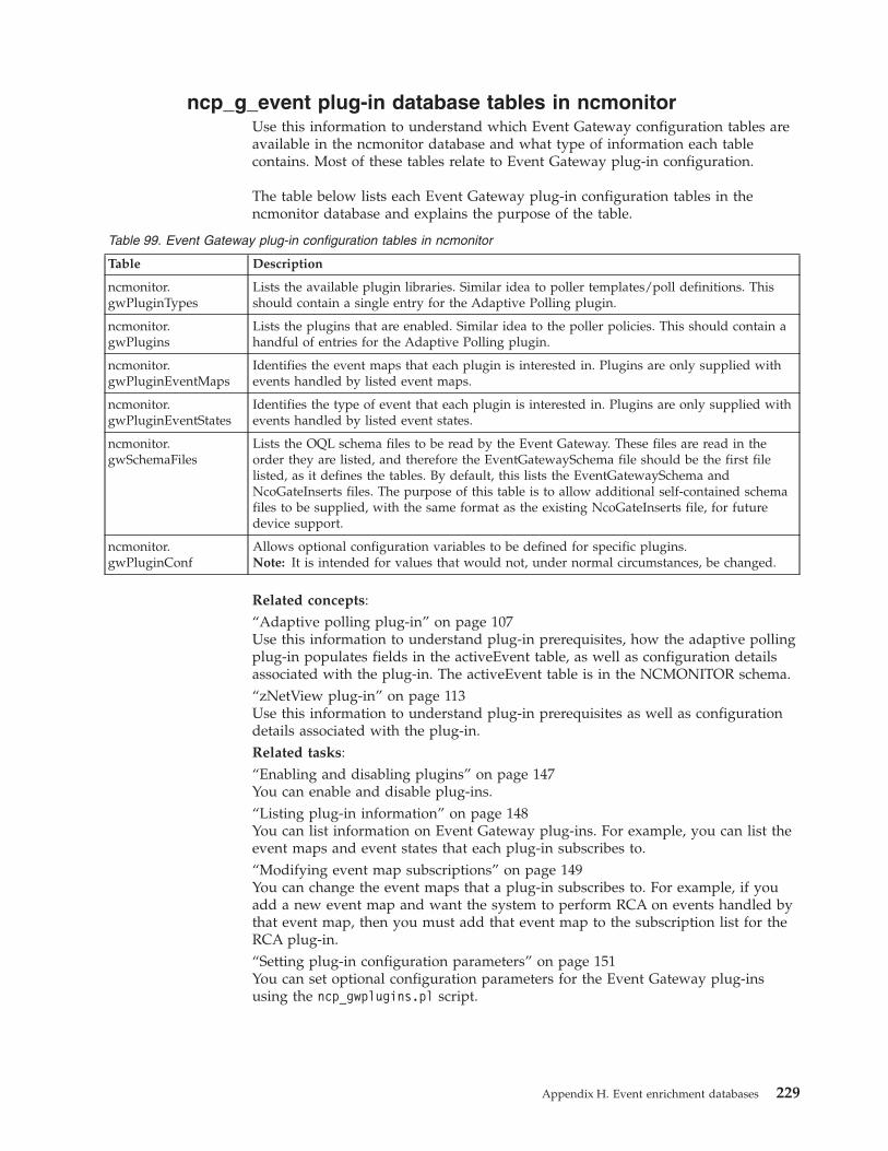
ncp_g_event plug-in database tables in ncmonitorUse this information to understand which Event Gateway configuration tables areavailable in the ncmonitor database and what type of information each tablecontains. Most of these tables relate to Event Gateway plug-in configuration.
The table below lists each Event Gateway plug-in configuration tables in thencmonitor database and explains the purpose of the table.
Table 99. Event Gateway plug-in configuration tables in ncmonitor
Table Description
ncmonitor.gwPluginTypes
Lists the available plugin libraries. Similar idea to poller templates/poll definitions. Thisshould contain a single entry for the Adaptive Polling plugin.
ncmonitor.gwPlugins
Lists the plugins that are enabled. Similar idea to the poller policies. This should contain ahandful of entries for the Adaptive Polling plugin.
ncmonitor.gwPluginEventMaps
Identifies the event maps that each plugin is interested in. Plugins are only supplied withevents handled by listed event maps.
ncmonitor.gwPluginEventStates
Identifies the type of event that each plugin is interested in. Plugins are only supplied withevents handled by listed event states.
ncmonitor.gwSchemaFiles
Lists the OQL schema files to be read by the Event Gateway. These files are read in theorder they are listed, and therefore the EventGatewaySchema file should be the first filelisted, as it defines the tables. By default, this lists the EventGatewaySchema andNcoGateInserts files. The purpose of this table is to allow additional self-contained schemafiles to be supplied, with the same format as the existing NcoGateInserts file, for futuredevice support.
ncmonitor.gwPluginConf
Allows optional configuration variables to be defined for specific plugins.Note: It is intended for values that would not, under normal circumstances, be changed.
Related concepts:“Adaptive polling plug-in” on page 107Use this information to understand plug-in prerequisites, how the adaptive pollingplug-in populates fields in the activeEvent table, as well as configuration detailsassociated with the plug-in. The activeEvent table is in the NCMONITOR schema.“zNetView plug-in” on page 113Use this information to understand plug-in prerequisites as well as configurationdetails associated with the plug-in.Related tasks:“Enabling and disabling plugins” on page 147You can enable and disable plug-ins.“Listing plug-in information” on page 148You can list information on Event Gateway plug-ins. For example, you can list theevent maps and event states that each plug-in subscribes to.“Modifying event map subscriptions” on page 149You can change the event maps that a plug-in subscribes to. For example, if youadd a new event map and want the system to perform RCA on events handled bythat event map, then you must add that event map to the subscription list for theRCA plug-in.“Setting plug-in configuration parameters” on page 151You can set optional configuration parameters for the Event Gateway plug-insusing the ncp_gwplugins.pl script.
Appendix H. Event enrichment databases 229

230 IBM Tivoli Network Manager IP Edition: Event Management Guide
Appendix I. Network Manager glossary
Use this information to understand terminology relevant to the Network Managerproduct.
The following list provides explanations for Network Manager terminology.
AOC filesFiles used by the Active Object Class manager, ncp_class to classifynetwork devices following a discovery. Device classification is defined inAOC files by using a set of filters on the object ID and other device MIBparameters.
active object class (AOC)An element in the predefined hierarchical topology of network devicesused by the Active Object Class manager, ncp_class, to classify discovereddevices following a discovery.
agent See, discovery agent.
bookmarkSee, network view bookmark.
class hierarchyPredefined hierarchical topology of network devices used by the ActiveObject Class manager, ncp_class, to classify discovered devices following adiscovery.
configuration filesEach Network Manager process has one or more configuration files used tocontrol process behaviour by setting values in the process databases.Configuration files can also be made domain-specific.
discovery agentPiece of code that runs during a discovery and retrieves detailedinformation from discovered devices.
Discovery Configuration GUIGUI used to configure discovery parameters.
Discovery engine (ncp_disco)Network Manager process that performs network discovery.
discovery phaseA network discovery is divided into four phases: Interrogating devices,Resolving addresses, Downloading connections, and Correlatingconnectivity.
discovery seedOne or more devices from which the discovery starts.
discovery scopeThe boundaries of a discovery, expressed as one or more subnets andnetmasks.
Discovery Status GUIGUI used to launch and monitor a running discovery.
discovery stitcherPiece of code used during the discovery process. There are various
© Copyright IBM Corp. 2006, 2013 231
discovery stitchers, and they can be grouped into two types: data collectionstitchers, which transfer data between databases during the data collectionphases of a discovery, and data processing stitchers, which build thenetwork topology during the data processing phase.
dNCIM databaseThe dNCIM is a relational database embedded into the Discovery engine,ncp_disco, and it stores the containment model that is derived from thefullTopology database (and created by stitchers). This is the version of thetopology that is sent to the Topology manager, ncp_model. The dNCIMdatabase performs the same function as the scratchTopology database didin previous versions of Network Manager.
domainSee, network domain.
entity A topology database concept. All devices and device componentsdiscovered by Network Manager are entities. Also device collections suchas VPNs and VLANs, as well as pieces of topology that form a complexconnection, are entities.
event enrichmentThe process of adding topology information to the event.
Event Gateway (ncp_g_event)Network Manager process that performs event enrichment.
Event Gateway stitcherStitchers that perform topology lookup as part of the event enrichmentprocess.
failoverIn your Network Manager environment, a failover architecture can be usedto configure your system for high availability, minimizing the impact ofcomputer or network failure.
Failover plug-inReceives Network Manager health check events from the Event Gatewayand passes these events to the Virtual Domain process, which decideswhether or not to initiate failover based on the event.
Fault Finding ViewComposite GUI view consisting of an Active Event List (AEL) portletabove and a Network Hop View portlet below. Use the Fault Finding Viewto monitor network events.
full discoveryA discovery run with a large scope, intended to discover all of the networkdevices that you want to manage. Full discoveries are usually just calleddiscoveries, unless they are being contrasted with partial discoveries. Seealso, partial discovery.
message brokerComponent that manages communication between Network Managerprocesses. The message broker used byNetwork Manager is called ReallySmall Message Broker. To ensure correct operation of Network Manager,Really Small Message Broker must be running at all times.
NCIM databaseRelational database that stores topology data, as well as administrativedata such as data associated with poll policies and definitions, andperformance data from devices.
232 IBM Tivoli Network Manager IP Edition: Event Management Guide
ncp_discoSee, Discovery engine.
ncp_g_eventSee, Event Gateway.
ncp_modelSee, Topology manager.
ncp_pollerSee, Polling engine.
network domainA collection of network entities to be discovered and managed. A singleNetwork Manager installation can manage multiple network domains.
Network Health ViewComposite GUI view consisting of a Network Views portlet above and anActive Event List (AEL) portlet below. Use the Network Health View todisplay events on network devices.
Network Hop ViewNetwork visualization GUI. Use the Network Hop View to search thenetwork for a specific device and display a specified network device. Youcan also use the Network Hop View as a starting point for networktroubleshooting. Formerly known as the Hop View.
Network Polling GUIAdministrator GUI. Enables definition of poll policies and poll definitions.
Network ViewsNetwork visualization GUI that shows hierarchically organized views of adiscovered network. Use the Network Views to view the results of adiscovery and to troubleshoot network problems.
network view bookmarkNetwork view bookmarks group together just those network views thatyou or your team need to monitor. Create new bookmarks or changeexisting bookmarks to help network operators visualize just those devicesthat they need to monitor.
OQL databasesNetwork Manager processes store configuration, management andoperational information in OQL databases.
OQL languageVersion of the Structured Query Language (SQL) that has been designedfor use in Network Manager. Network Manager processes create andinteract with their databases using OQL.
partial discoveryA subsequent rediscovery of a section of the previously discoverednetwork. The section of the network is usually defined using a discoveryscope consisting of either an address range, a single device, or a group ofdevices. A partial discovery relies on the results of the last full discovery,and can only be run if the Discovery engine, ncp_disco, has not beenstopped since the last full discovery. See also, full discovery.
Path ViewsNetwork visualization GUI that displays devices and links that make up a
Appendix I. Network Manager glossary 233
network path between two selected devices. Create new path views orchange existing path views to help network operators visualize networkpaths.
performance dataPerformance data can be gathered using performance reports. Thesereports allow you to view any historical performance data that has beencollected by the monitoring system for diagnostic purposes.
Polling engine (ncp_poller)Network Manager process that polls target devices and interfaces. ThePolling engine also collects performance data from polled devices.
poll definitionDefines how to poll a network device or interface and further filter thetarget devices or interfaces.
poll policyDefines which devices to poll. Also defines other attributes of a poll suchas poll frequency.
Probe for Tivoli Netcool/OMNIbus (nco_p_ncpmonitor)Acquires and processes the events that are generated by Network Managerpolls and processes, and forwards these events to the ObjectServer.
RCA plug-inBased on data in the event and based on the discovered topology, attemptsto identify events that are caused by or cause other events using rulescoded in RCA stitchers.
RCA stitcherStitchers that process a trigger event as it passes through the RCA plug-in.
root-cause analysis (RCA)The process of determining the root cause of one or more device alerts.
SNMP MIB BrowserGUI that retrieves MIB variable information from network devices tosupport diagnosis of network problems.
SNMP MIB GrapherGUI that displays a real-time graph of MIB variables for a device and ussethe graph for fault analysis and resolution of network problems.
stitcherCode used in the following processes: discovery, event enrichment, androot-cause analysis. See also, discovery stitcher, Event Gateway stitcher,and RCA stitcher.
Structure BrowserGUI that enables you to investigate the health of device components inorder to isolate faults within a network device.
Topology Manager (ncp_model)Stores the topology data following a discovery and sends the topologydata to the NCIM topology database where it can be queried using SQL.
WebToolsSpecialized data retrieval tools that retrieve data from network devices andcan be launched from the network visualization GUIs, Network Views andNetwork Hop View, or by specifying a URL in a web browser.
234 IBM Tivoli Network Manager IP Edition: Event Management Guide
Notices
This information applies to the PDF documentation set for IBM Tivoli NetworkManager IP Edition.
This information was developed for products and services offered in the U.S.A.
IBM may not offer the products, services, or features discussed in this document inother countries. Consult your local IBM representative for information on theproducts and services currently available in your area. Any reference to an IBMproduct, program, or service is not intended to state or imply that only that IBMproduct, program, or service may be used. Any functionally equivalent product,program, or service that does not infringe any IBM intellectual property right maybe used instead. However, it is the user's responsibility to evaluate and verify theoperation of any non-IBM product, program, or service.
IBM may have patents or pending patent applications covering subject matterdescribed in this document. The furnishing of this document does not grant youany license to these patents. You can send license inquiries, in writing, to:
IBM Director of LicensingIBM CorporationNorth Castle DriveArmonk, NY 10504-1785U.S.A.
For license inquiries regarding double-byte character set (DBCS) information,contact the IBM Intellectual Property Department in your country or sendinquiries, in writing, to:
Intellectual Property LicensingLegal and Intellectual Property LawIBM Japan, Ltd.19-21, Nihonbashi-Hakozakicho, Chuo-kuTokyo 103-8510, Japan
The following paragraph does not apply to the United Kingdom or any othercountry where such provisions are inconsistent with local law: INTERNATIONALBUSINESS MACHINES CORPORATION PROVIDES THIS PUBLICATION "AS IS"WITHOUT WARRANTY OF ANY KIND, EITHER EXPRESS OR IMPLIED,INCLUDING, BUT NOT LIMITED TO, THE IMPLIED WARRANTIES OFNON-INFRINGEMENT, MERCHANTABILITY OR FITNESS FOR A PARTICULARPURPOSE. Some states do not allow disclaimer of express or implied warranties incertain transactions, therefore, this statement may not apply to you.
This information could include technical inaccuracies or typographical errors.Changes are periodically made to the information herein; these changes will beincorporated in new editions of the publication. IBM may make improvementsand/or changes in the product(s) and/or the program(s) described in thispublication at any time without notice.
Any references in this information to non-IBM Web sites are provided forconvenience only and do not in any manner serve as an endorsement of those Web
© Copyright IBM Corp. 2006, 2013 235
sites. The materials at those Web sites are not part of the materials for this IBMproduct and use of those Web sites is at your own risk.
IBM may use or distribute any of the information you supply in any way itbelieves appropriate without incurring any obligation to you.
Licensees of this program who wish to have information about it for the purposeof enabling: (i) the exchange of information between independently createdprograms and other programs (including this one) and (ii) the mutual use of theinformation which has been exchanged, should contact:
IBM Corporation958/NH04IBM Centre, St Leonards601 Pacific HwySt Leonards, NSW, 2069AustraliaIBM Corporation896471/H128B76 Upper GroundLondonSE1 9PZUnited KingdomIBM CorporationJBF1/SOM1 294Route 100Somers, NY, 10589-0100United States of America
Such information may be available, subject to appropriate terms and conditions,including in some cases, payment of a fee.
The licensed program described in this document and all licensed materialavailable for it are provided by IBM under terms of the IBM Customer Agreement,IBM International Program License Agreement or any equivalent agreementbetween us.
Any performance data contained herein was determined in a controlledenvironment. Therefore, the results obtained in other operating environments mayvary significantly. Some measurements may have been made on development-levelsystems and there is no guarantee that these measurements will be the same ongenerally available systems. Furthermore, some measurements may have beenestimated through extrapolation. Actual results may vary. Users of this documentshould verify the applicable data for their specific environment.
Information concerning non-IBM products was obtained from the suppliers ofthose products, their published announcements or other publicly available sources.IBM has not tested those products and cannot confirm the accuracy ofperformance, compatibility or any other claims related to non-IBM products.Questions on the capabilities of non-IBM products should be addressed to thesuppliers of those products.
This information contains examples of data and reports used in daily businessoperations. To illustrate them as completely as possible, the examples include the
236 IBM Tivoli Network Manager IP Edition: Event Management Guide
names of individuals, companies, brands, and products. All of these names arefictitious and any similarity to the names and addresses used by an actual businessenterprise is entirely coincidental.
COPYRIGHT LICENSE:
This information contains sample application programs in source language, whichillustrate programming techniques on various operating platforms. You may copy,modify, and distribute these sample programs in any form without payment toIBM, for the purposes of developing, using, marketing or distributing applicationprograms conforming to the application programming interface for the operatingplatform for which the sample programs are written. These examples have notbeen thoroughly tested under all conditions. IBM, therefore, cannot guarantee orimply reliability, serviceability, or function of these programs.
TrademarksThe terms in Table 100 are trademarks of International Business MachinesCorporation in the United States, other countries, or both:
Table 100. IBM trademarks
AIX® Informix® RDN®
BNT iSeries® solidDB®
ClearQuest® Lotus® System p
Cognos® Netcool® System z®
DB2® NetView® Tivoli
DB2 UniversalDatabase
Notes® WebSphere®
developerWorks® OMEGAMON® z/OS
DS8000 PowerPC z/VM®
EnterpriseStorage Server®
PowerVM® zSeries
IBM PR/SM™
Intel, Intel logo, Intel Inside, Intel Inside logo, Intel Centrino, Intel Centrino logo,Celeron, Intel Xeon, Intel SpeedStep, Itanium, and Pentium are trademarks orregistered trademarks of Intel Corporation or its subsidiaries in the United Statesand other countries.
Java™ and all Java-based trademarks and logos are trademarks orregistered trademarks of Oracle and/or its affiliates.
Notices 237
Linux is a registered trademark of Linus Torvalds in the United States, othercountries, or both.
UNIX is a registered trademark of The Open Group in the United States and othercountries.
Microsoft, Windows, Windows NT, and the Windows logo are trademarks ofMicrosoft Corporation in the United States, other countries, or both.
Privacy policy considerations
IBM Software products, including software as a service solutions, ("SoftwareOfferings") may use cookies or other technologies to collect product usageinformation, to help improve the end user experience, to tailor interactions withthe end user or for other purposes. In many cases no personally identifiableinformation is collected by the Software Offerings. Some of our Software Offeringscan help enable you to collect personally identifiable information. If this SoftwareOffering uses cookies to collect personally identifiable information, specificinformation about this offering's use of cookies is set forth below.
This Software Offering may collect IP addresses, user names and passwords for thepurpose of performing network discovery. Failure to enable the collection of thisinformation would likely eliminate important functionality provided by thisSoftware Offering. You as customer should seek your own legal advice about anylaws applicable to such data collection, including any requirements for notice andconsent.
For more information about the use of various technologies, including cookies, forthese purposes, See IBM's Privacy Policy at http://www.ibm.com/privacy andIBM's Online Privacy Statement at http://www.ibm.com/privacy/details thesection entitled "Cookies, Web Beacons and Other Technologies" and the "IBMSoftware Products and Software-as-a-Service Privacy Statement" athttp://www.ibm.com/software/info/product-privacy.
238 IBM Tivoli Network Manager IP Edition: Event Management Guide
Index
Special characters<$nopage>root cause analysis, see RCA
examples 127poller entity 128
Aaccessibility xadaptive polling
managing 49adaptive polling plug-in 107adaptive polling scenario
confirmation of thresholdviolation 52
device down confirmation 49adaptive polling scenarios 49adaptive polls
creating 55adding SAE types to SAE plug-in 153administering
historical polling 65multiple poller feature 61network polling 57poll policy throttling 60polls 57
alerts.status tablefields used for Network
Manager 187AMOS process
root cause analysis 129audience v
Bbasic threshold expression
example 42basic threshold policies
default 160basic threshold poll definitions
changing 34creation 21
basic threshold pollschanging 29
Ccards
entities 131changing
basic threshold poll definitions 34chassis ping poll definitions 38generic threshold poll definitions 36interface ping poll definitions 38interval for checking poll policy
membership size 60link state poll definitions 40poll definitions 34poll policies 29remote ping poll definitions 40
changing poll definitionsexample 41
chassis devicesdownstream 132
chassis ping poll definitionschanging 38creating 25
chassisOnlyIps view 209Chinese characters
See multibyte dataclear threshold
example 173commands
SIGHUP 145config database 219
for polling 211config.defaults database 220
root cause analysis 226config.eventMaps 222config.eventMaps database 222config.failover database 224config.failover table
for polling 213config.nco2ncp database 223config.ncp2nco database 224config.ncp2nco table 224config.precedence database 221config.properties table
for polling 211config.pruning table
for polling 214config.realTimeControl table
for polling 213config.serviceTypes table 228configuration parameters for Event
Gateway plug-inssetting 151
configuringevent enrichment 139Event Gateway plug-ins 147extra event enrichment 139poller entity 155RCA plug-in 155root-cause analysis 155SAE plug-in 152
connected interfaces 130connecting entities 131contained interfaces 129conventions, typeface xiicopying
get_policies.pl program 58polls
across domains 58creating
adaptive polls 55basic threshold poll definitions 21chassis ping poll definitions 25generic threshold poll definitions 23interface ping poll definitions 25link state poll definitions 27poll definitions 21
creating (continued)remote ping poll definitions 27
Ddata extraction stitchers 97data labels 9database tables
RCA plug-in 224SAE plug-in 227
databases 222, 224config 219config.defaults 220, 226config.failover 224config.nco2ncp 223config.precedence 221for event enrichment 219for polling 199gateway 219mojo.events 224ncmonitor 199ncp_g_event 219
databases for pollingconfig.failover table 213config.properties table 211config.pruning table 214config.realTimeControl table 213profiling.engine table 216profiling.icmp table 215profiling.policy table 214profiling.snmp table 215
default event maps 86default precedence values 119defining using multibyte data 10delayedPollPolicies view 207deleting
poll definitions 47poll policies 45
descriptionsRCA stitchers 126
deviceschassis 130, 132Chassis 129main node 129
disablingEvent Gateway plug-ins 147network view updates for poll
policies 60poll policies 57
disabling polls 11discoveredIps view 208downstream 128downstream chassis devices
root cause analysis 132downstream devices
root cause analysis 127
© Copyright IBM Corp. 2006, 2013 239

Eeducation
see Tivoli technical training xenabling
Event Gateway plug-ins 147network view updates for poll
policies 60poll policies 57
enabling polls 11entities
cards 131virtual routers 131VLANs 131
entity retrieval stitchers 98EntityFromIfString.stch 99environment variables, notation xiieval statement
in threshold expressions 175event categories 193event correlation 71event enrichment 71
assigning states to different eventtypes 80
configuring 139configuring extra event
enrichment 139data extraction stitchers 97enriching event with interface
name 141enriching event with main node
device location 140entity retrieval stitchers 98event enrichment stitchers 100event filter 73event filtering 73event handling 84event maps 84event state 80event state diagram 81example 103, 140, 141field filter 77incoming event filter 73incoming field filter 77outgoing field filter 77poller entity 128precedence value 118quick reference 71standby filter 76stitchers 93stitchers not used by default 102topology lookup stitchers 93
event enrichment databases 219event enrichment stitchers 100event fields 185event filter 73
incoming to Event Gateway 73event filtering 73Event Gateway
assigning states to different eventtypes 80
configuring 145configuring extra event
enrichment 139data extraction stitchers 97entity retrieval stitchers 98event enrichment stitchers 100event handling 84
Event Gateway (continued)event maps 84event state 80event state diagram 81filter 73incoming filter 73logging into the databases using
OQL 144methods for selecting event maps 85NcpServerEntity 120outgoing queue 78plug-in configuration tables 229poller entity 128Poller entity 120precedence value 118precedence values 119selecting event maps 84standby filter 76stitchers 90stitchers not used by default 102topology lookup stitchers 93
Event Gateway plug-in configurationparameters
setting 151Event Gateway plug-in information
listing 148Event Gateway plug-ins
configuring 147disabling 147enabling 147subscriptions 149
Event Gateway plugins 106RCA 117
Event Gateway SAE plug-inadding SAE types 153
Event Gateway stitchersexample 95, 97, 99, 101
event handling 84event map
selection 84selection methods 85selection using the Event
Gateway 84event mappings 222, 224event maps 84
default 86event state 80event state diagram 81event types 80events
maximum age difference forRCA 156
network 194service-affected (SAE)
summary fields 152status information 194
exampledata extraction stitcher 97entity retrieval stitcher 99event enrichment 103, 140, 141event enrichment stitcher 101Event Gateway stitcher 95, 97, 99,
101poll definition
example of thresholdexpression 42, 43
threshold expression 42, 43
example (continued)topology lookup stitcher 95
examplesthreshold polling 7
expectedIps table 202extra event enrichment
configuring 139ExtractIfString.stch 97
Ffailover plug-in 109failures
chassis 130field filter 77field mappings
Network Manager toalerts.status 187
filterincoming to Event Gateway 73
Ggeneric threshold expression
example 43generic threshold policies
default 160generic threshold poll definitions
changing 36creation 23
generic threshold pollschanging 29examples 173
glossary 231
Hhistorical polling
administering 65deleting data 66
Iincoming event filter 73incoming field filter 77interface ping poll definitions
changing 38creating 25
interfaces 133contained 129downstream 130loopback 129upstream 130
interval for checking poll policymembership size
changing 60isolated suppression 132, 135ITNCM plug-in 110
Llink state poll definitions
changing 40creating 27
240 IBM Tivoli Network Manager IP Edition: Event Management Guide
link state pollschanging 29
listingEvent Gateway plug-in
information 148locales
See multibyte datalookup stitchers 93LookupIp.stch 95loopback interfaces 129
Mmanaged status
and RCA 122managementInterfaceIps view 209managing
adaptive polling 49manuals viimaximum age differencefor RCA 156membership size of poll policies
changing checking interval 60mojo.events database
root cause analysis 224multibyte data
in poll definitions 10multiple poller feature
adding poller 62administering 61overview 62removing poller 64
NNCIM database
querying using OQL 144NCMONITOR
polling databases 199polling status tables 202
ncmonitor databasechassisOnlyIps view 209delayedPollPolicies view 207discoveredIps view 208Event Gateway plug-in configuration
tables 229expectedIps table 202managementInterfaceIps view 209pollLog table 202pollLogSummary table 204SNMP 199snmpAccess table 200snmpTarget table 199snmpUser table 201snmpv1Sec table 201snmpv3Sec table 201undiscoveredIps view 205unmanagedIps view 206unmonitoredIps view 205unpollableIps view 210unpolledFor15MinutesIps view 207
ncp_g_event 219NcPollerSchema.cfg 66NcpServerEntity 120network events 194Network Manager event categories 193Network Manager event fields 185
Network Manager glossary 231Network Manager to alerts.status
mappings 187network polling
administering 57network view updates for poll policies
disabling 60enabling 60
OObjectServer
querying using OQL 144online publications viioperators
in threshold expressions 178OQL polling databases 211ordering publications viioutgoing field filter 77outgoing queue
on Event Gateway 78overview
multiple poller feature 62
Pparameters
of poll definitions 4of poll policies 2
ping policiesdefault 159
ping pollingoverview 5poll definition types 8
ping pollschanging 29
plug-inquick reference for RCA 118
plug-in configuration parameterssetting 151
plug-in informationlisting 148
plug-insadaptive polling 107configuration tables 229configuring 147disabling 147enabling 147failover 109ITNCM 110PostNCIMProcessing 111SAE 112subscriptions 149zNetView 113
plugins 106event map subscriptions 114
for plugins 114RCA 117
policy throttlingadministering 60
Poll Definition Editor 21poll definition types 8poll definitions 10
changing 34example 41
creation 21
poll definitions (continued)data labels 9defaults 165definition 4deletion 47mechanisms
ping 5SNMP 5
overview 4parameters 4remote ping 6SNMP link state 5threshold 7threshold expressions 175
poll policieschanging 29defaults
basic threshold 160generic threshold 160ping 159remote ping 159reporting 163
definition 2deletion 45disabling 57enabling 57example 32overview 2parameters 2refreshing 58retrieving status 57
poll policyscope 2
poll policy membership sizechanging checking interval 60
poll policy network view updatesdisabling 60enabling 60
poll policy throttlingadministering 60
polleradding 62removing 64
poller entity 128configuring 155
Poller entity 120polling
adaptive polling scenarios 49administering network polling 57default probes 1managing adaptive polling 49overview 1
polling databaseembedded OQL databases 211
polling databases 199config database 211config.failover table 213config.properties table 211config.pruning table 214config.realTimeControl table 213NCMONITOR 199profiling database 214profiling.engine table 216profiling.icmp table 215profiling.policy table 214profiling.snmp table 215
polling status tables 202
Index 241
pollLog table 202pollLogSummary table 204polls
across domains 58administering 57copying 58disabling 11enabling 11
PostNCIMProcessing plug-in 111precedence value 118precedence values
defaults 119Probe for Tivoli Netcool/OMNIbus
configuring 181properties file 181rules file 182
processfor event enrichment 71
processesevents generated 194
profiling databasefor polling 214
profiling.engine tablefor polling 216
profiling.icmp tablefor polling 215
profiling.policy tablefor polling 214
profiling.snmp tablefor polling 215
programsget_policies.pl 58
publications vii
Qquerying
NCIM database using OQL 144ObjectServer using OQL 144
queueoutgoing on Event Gateway 78
quick referenceevent enrichment 71RCA plug-in 118
RRCA 117
and managed status 122configuring 155isolated suppression 132, 135maximum age difference for
suppression 156precedence value 118precedence values 119
RCA exampleconnected interfaces 130contained interfaces 129directly connected interface 134related logical interface 134
RCA plug-inconfiguring 155database tables 224quick reference 118
RCA stitchers 123descriptions 126
RCA stitchers (continued)sequence 123
referenceevent enrichment 71RCA plug-in 118
refreshingpoll policies 58
remote ping policiesdefault 159
remote ping poll definitionschanging 40creating 27
remote ping pollingoverview 6restrictions 6
reporting policiesdefault 163
retrievingstatus of poll policies 57
root cause analysis 129AMOS process 129config.defaults database 226contained interfaces 129downstream chassis devices 132mojo.events database 224
Root Cause Analysisisolated suppression 132, 135
root-cause analysis 117configuring 155maximum age difference for
suppression 156rules file processing example 183
SSAE plug-in 112
adding SAE types 153config.serviceTypes table 228configuring 152database tables 227
SAEsconfiguring summary fields 152
scenariosfor adaptive polling 49
scopeof poll policy 2
selectionof event map 84of event map using the Event
Gateway 84selection methods
for event map 85sequence
RCA stitchers 123service xiservice management connect xisetting
Event Gateway plug-in configurationparameters 151
SIGHUP command 145SMC xiSNMP
ncmonitor database 199SNMP link state polling
overview 5SNMP polling
overview 5
SNMP polling (continued)poll definition types 8
snmpAccess table 200snmpTarget table 199snmpUser table 201snmpv1Sec table 201snmpv3Sec table 201StandardEventEnrichment.stch 101standby filter 76state
of events 80status information events 194stitchers
example for Event Gateway 95, 97,99, 101
examples of Event Gateway stitchersnot used by default 102
ExtractIfString.stch 97, 99for data extraction 97for entity retrieval 98for event enrichment 93, 100for Event Gateway 90for topology lookup 93LookupIp.stch 95RCA stitcher descriptions 126RCA stitcher sequence 123StandardEventEnrichment.stch 101
storing ping response times 66subscriptions
for Event Gateway plug-ins 149support xisupport information xi
Ttables
expectedIps 202pollLog 202pollLogSummary 204snmpAccess 200snmpTarget 199snmpUser 201snmpv1Sec 201snmpv3Sec 201
threshold expressionexample 42, 43
threshold expressionsoperators 178syntax 175use of the eval statement 175
threshold pollingexample 7overview 7
throttlingadministering 60
Tivoli software information center viiTivoli technical training xtopology lookup stitchers 93training, Tivoli technical xtrigger threshold
example 173typeface conventions xii
242 IBM Tivoli Network Manager IP Edition: Event Management Guide

UundiscoveredIps view 205unmanagedIps view 206unmonitoredIps view 205unpollableIps view 210unpolledFor15MinutesIps view 207upstream 128upstream devices
root cause analysis 127
Vvariables, notation for xiiviews
chassisOnlyIps 209delayedPollPolicies 207discoveredIps 208managementInterfaceIps 209undiscoveredIps 205unmanagedIps 206unmonitoredIps 205unpollableIps 210unpolledFor15MinutesIps 207
virtual routersentities 131
VLANsentities 131
ZzNetView plug-in 113
Index 243

244 IBM Tivoli Network Manager IP Edition: Event Management Guide


����
Printed in the Republic of Ireland