evandro lab 4
TRANSCRIPT

ELC LAB 5 212086561
1
Table of Contents Introduction ........................................................................................................................................................ 2
Theory ................................................................................................................................................................. 2
Equipment used .................................................................................................................................................. 5
Procedures .......................................................................................................................................................... 5
Results ................................................................................................................................................................. 8
Discussion of results ........................................................................................................................................... 9
Analysis ............................................................................................................................................................... 9
Compare the values of VAB and IL in Norton’s experiment with those obtained in in case the circuit is
treated as Thevenin’s circuit. Is theory of source transformation verified? ...................................................... 9
When the Norton’s equivalent circuit is established and is compared with the thevenin’s equivalent circuit
they behave in exactly the same way due to the fact that they are just a source transformation of each
other. .................................................................................................................................................................. 9
On what grounds one can say that Thevenin and Norton are the source transformation of each
other?.................................................................................................................................................................. 9
Referring to the observation tables 3 and 4, how much current will be supplied by the source?
Justify your answer mathematically. .................................................................................................................. 9
The relationship between power absorbed for the networks of Figure 4 and 5, what can you infer from
it? [Hint: Talk in terms of resistance] ................................................................................................................ 10
Conclusion ......................................................................................................................................................... 10
REFERENCES ................................................................................................................................................. 11

ELC LAB 5 212086561
2
Introduction
Electricity is an essential part of the modern life experience, and as an engineer it is essential to know
how it behaves and responds to changes in its trajectory. This lab was divided into two parts namely
Part 1 you work with Norton`s theorem and part 2 is all about delta/ star transformations. The main
goal of the lab is to verify Norton’s Theorem and the theory of Star – Delta transformation. The
purpose is to get familiarized with lab equipment be able to make simple circuit connections and
successfully be able to extract experimental data from such connected circuit.
Theory
Basic definitions needed for the complete understanding of the content of this report :
Voltage is electrical potential energy per unit charge which is measured in joules per coulomb
which has its SI unit as volts.
Resistance is defined as the opposition within a conductor to the passage of electric current which
has its SI unit as Ohms (Ω). Carbon resistor are the components which are placed in a circuit to
oppose current flow.
Power supply is a device that supplies electric power to an electrical load.
Norton's Theorem
Norton's theorem states that any two terminal networks may be replaced by a simple equivalent
circuit consisting of a constant current source IN, shunted by an internal resistance RN,. The
Norton current IN is distributed between the shunt resistance RN and the load RL. The current
IL in RL may be found from the equation NN L NL I xRI RR = + The rules for determining the
constants in the Norton equivalent circuit are as follows:
1 The constant current IN is the current that would flow in the short circuit between the load
resistance terminals if the load resistance were replaced by a short circuit.
2 The Norton resistance RN is the resistance seen from the terminals of the open load, looking
into the original network, when the voltage sources in the circuit are replaced by their internal
resistance. Thus RN is defined in exactly the same manner as is RTH in Thevenin’s theorem.
The theory of source conversion says that the Norton and Thevenin’s circuits can be terminally
equivalent and related as follows:
Figure 1a shows the original network as a block terminated by a load resistance RL. Figure 1b
shows the Norton equivalent circuit

ELC LAB 5 212086561
3
Figure 1
Figure 2
ELC LAB 5 212086561
4
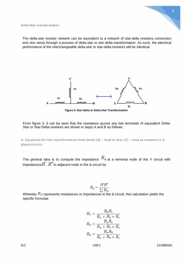
Delta-Star transformation
The delta-star resistor network can be equivalent to a network of star-delta resistors connection
and vice versa through a process of delta-star or star-delta transformation .As such, the electrical
performance of the interchangeable delta-star or star-delta resistors will be Identical.
Figure 3: Star-delta or Delta-Star Transformation
From figure 3, it can be seen that the resistance across any two terminals of equivalent Delta- Star or Star-Delta resistors are shown in steps A and B as follows:
A. Equations for the transformation from Delta (Δ) – load to Star (Y) – load as common in 3-
phase circuits
The general idea is to compute the impedance at a terminal node of the Y circuit with
impedances , to adjacent node in the Δ circuit by
Whereby represents resistances or impedances in the Δ circuit, this calculation yields the
specific formulae
ELC LAB 5 212086561
5
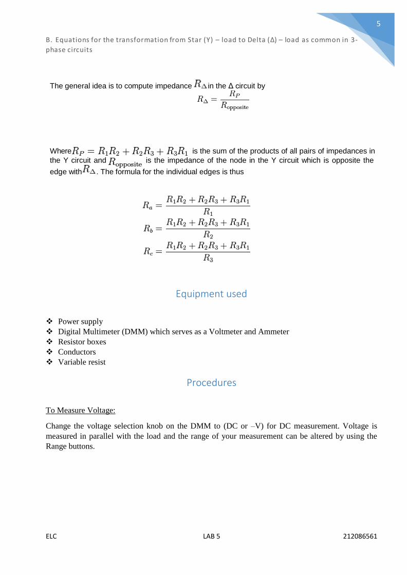
B. Equations for the transformation from Star (Y) – load to Delta (Δ) – load as common in 3-
phase circuits
The general idea is to compute impedance in the Δ circuit by
Where is the sum of the products of all pairs of impedances in
the Y circuit and is the impedance of the node in the Y circuit which is opposite the
edge with . The formula for the individual edges is thus
Equipment used
Power supply
Digital Multimeter (DMM) which serves as a Voltmeter and Ammeter
Resistor boxes
Conductors
Variable resist
Procedures
To Measure Voltage:
Change the voltage selection knob on the DMM to (DC or –V) for DC measurement. Voltage is
measured in parallel with the load and the range of your measurement can be altered by using the
Range buttons.
ELC LAB 5 212086561
6
To Measure Current:
Change the current outlet of the DMM to (“+” terminal) and the COM outlet (ground). Current is
measured in series you will have to break the circuit to measure current. For a current less than
200mA use the outlet (VΩA) and for current greater than 200mA use the outlet written 20A
in red else the DMM will not be accurate and may not show the current reading. You can vary the
range of your measurement by using the Range buttons.
To Measure Power Supply Voltage:
A voltmeter is always connected in parallel across your load or power supply. The “+” terminal of the
voltmeter should be connected to the “+” terminal of the Power Supply hence forth referred to as (PS)
(usually the red outlet) and the “-” terminal of the voltmeter to the “-” terminal of the PS (usually the
COM or black outlet) of the DMM.
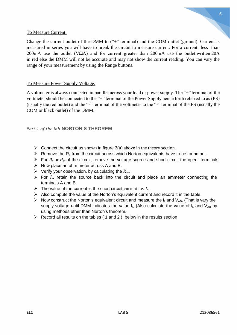
Part 1 of the lab NORTON’S THEOREM
Connect the circuit as shown in figure 2(a) above in the theory section. Remove the RL from the circuit across which Norton equivalents have to be found out. For RN or RTH of the circuit, remove the voltage source and short circuit the open terminals. Now place an ohm meter across A and B. Verify your observation, by calculating the RTH.
For IN, retain the source back into the circuit and place an ammeter connecting the
terminals A and B. The value of the current is the short circuit current i.e. IN. Also compute the value of the Norton’s equivalent current and record it in the table. Now construct the Norton’s equivalent circuit and measure the IL and VAB. (That is vary the
supply voltage until DMM indicates the value IN )Also calculate the value of IL and VAB by
using methods other than Norton’s theorem. Record all results on the tables ( 1 and 2 ) below in the results section

ELC LAB 5 212086561
7
Part 2 of the lab. DELTA-STAR TRANSFORMATION
Figure 4: Resistors in Delta
Connect circuit in Figure 4:R1=3kΩ , R2=3kΩ , R3=1kΩ , R4=2kΩ , R5=3kΩ ,V1=10 VDC
Measure the voltage VAB and record in Table :3 Measure the currents I1,I2 IT ,and IAB and record in Table:3 below in the results section and
calculate power across AB
Figure 5: Resistors in Star-Connection
Connect circuit in figure 5 and adjust Ra to 1 kΩ
Measure the voltage VAB and record in Table :4 Measure the currents I1,I2 IT ,and IAB and record in Table:4 and calculate power across AB Adjust variable resistor (RA) and repeat steps (b) and (c).
ELC LAB 5 212086561
8
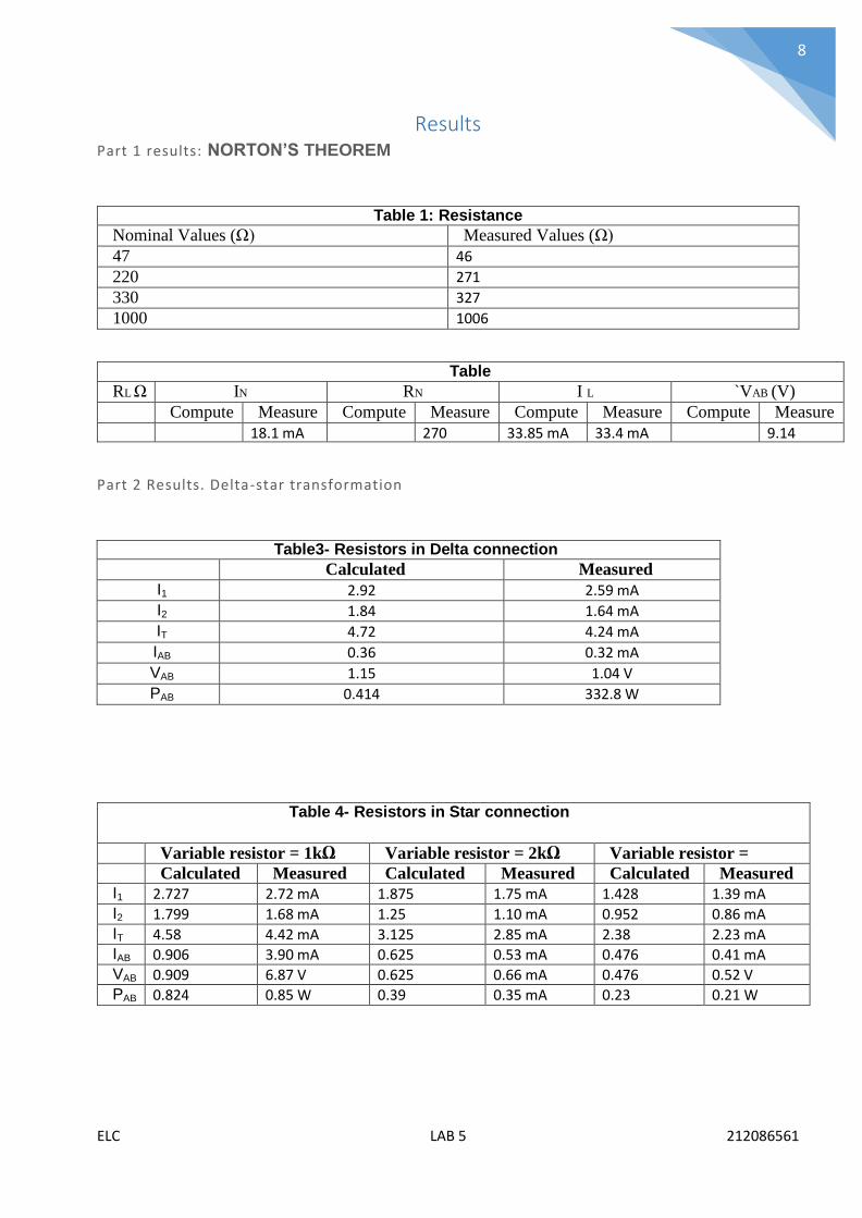
Results Part 1 results: NORTON’S THEOREM
Table 1: Resistance values Nominal Values (Ω) Measured Values (Ω)
47 46
220 271
330 327
1000 1006
Table 2: RL Ω IN
(A) RN
(Ω) I L
(A) `VAB (V)
Computed
Measured
Computed
Measured
Computed
Measured
Computed
Measured 18.1 mA 270 33.85 mA 33.4 mA 9.14
Part 2 Results. Delta-star transformation
Table3- Resistors in Delta connection
Calculated Measured I1 2.92 2.59 mA
I2 1.84 1.64 mA
IT 4.72 4.24 mA
IAB 0.36 0.32 mA
VAB 1.15 1.04 V
PAB 0.414 332.8 W
Table 4- Resistors in Star connection
Variable resistor = 1kΩ Variable resistor = 2kΩ Variable resistor = 3.23kΩ Calculated Measured Calculated Measured Calculated Measured
I1 2.727 2.72 mA 1.875 1.75 mA 1.428 1.39 mA I2 1.799 1.68 mA 1.25 1.10 mA 0.952 0.86 mA IT 4.58 4.42 mA 3.125 2.85 mA 2.38 2.23 mA IAB 0.906 3.90 mA 0.625 0.53 mA 0.476 0.41 mA VAB 0.909 6.87 V 0.625 0.66 mA 0.476 0.52 V PAB 0.824 0.85 W 0.39 0.35 mA 0.23 0.21 W

ELC LAB 5 212086561
9
Discussion of results
Analysis
Compare the values of VAB and IL in Norton’s experiment with those
obtained in in case the circuit is treated as Thevenin’s circuit. Is
theory of source transformation verified? (ANS)
When the Norton’s equivalent circuit is established and is compared with the thevenin’s
equivalent circuit they behave in exactly the same way due to the fact that they are just a
source transformation of each other.
On what grounds one can say that Thevenin and Norton are the
source transformation of each other? (ANS)
When the circuit has already been simplified and all that is left is a voltage source in series with a
resistance which is the thevenin’s equivalent. Now this thevenin equivalent circuit if source
transformed will result in the Norton`s equivalent circuit and vice versa.
Referring to the observation tables 3 and 4, how much current
will be supplied by the source? Justify your answer mathematically.
(ANS)
For table 3
The current generated by the source is the algebraic sum of the currents I1 and I2. Therefore 2.59+1.64mA=
4.23mA which can be verified in table three above.
For table 4
The current supplied by the source changes as the Req also changes due to the ohms law relationship which
states that R=V/I. Therefore the current supplied by the source shall be as follows
With a 1KΩ variable resistor… It= 2.72mA+1.68mA=4.4mA
With a 2 KΩ variable resistor… It=1.75mA+1.10mA=2.85mA
With the 3.2 KΩ variable resistor… It=1.39mA+0.86mA=2.25mA
Therefore as the total resistance increases so does the total current supplied decrease.
ELC LAB 5 212086561
10
The relationship between power absorbed for the networks of Figure
4 and 5, what can you infer from it? [Hint: Talk in terms of resistance]
(ANS)
Since the relationship between voltage and resistance to generate power is ( P=V2/R ) and due to the
different arrangements between the resistors in figures 4 and 5 will cause different values for the equivalent
resistances.
For figure 4 there shall be a smaller resistance than in figure 5. And due to the fact that the source voltages
remain the same the following conclusions can be made.
That there shall be more power dissipated in a circuit with an arrangement as in figure 4. And there
shall be less power dissipated in a circuit with an arrangement as the one in figure 5
Conclusion
In conclusion it is very well established mathematically and theoretically that the Norton`s equivalent circuit
and the thevenin`s equivalent circuit are very closely related to one another since one is a source
transformation of the other. Therefore according to ohms law the relationship between resistance voltage
and current allows us to theoretically prove the practical results that we have gotten. The delta star network
transformation aids in the simplification of the circuit for the analysis.
In addition this lab has been of immense interest as it has established some of the most common theories in
elc as true.

ELC LAB 5 212086561
11
REFERENCES
Bird, J. (2003). electrical circuit theory and thechnology. boston: Newnes.

12