european practice in refuse and sewage sludge disposal by ... · european practice • in refuse...
TRANSCRIPT
European Practice •
In Refuse
and
Sewage Sludge Disposal
by Incineration
Abstract
American and European incineration starts from two different prerequisites. In America, volume reduction of the refuse is strived fOf; in Europe the aim i s to com� pletely burn out the refuse, to utilize the waste heat, and to minimize air pollution as far as possible through the use of expensive lIue-gas cleaning equipment. Today, values that must be attained are 3 per ceht combustible constituents in the residue, 0.1-0.2 per cent putrefying substance, and 0.04 grains of dust per ;td cu ft of lIue gas.
The combination of refuse incineration and large power-station boilers is becoming more and more frequent. This can be attributed to the favorable financing possibilities by the States for electric companies with additional incineration of household and industrial refuse. This explains our development of large boiler plants with high steam temperatures and pressures which have been combined with refuse incineration.
Possible corrosion problems seemed formidable at first, but today means are available to substantially prevent s';ch damage and to improve the availability of combined refuse boiler units.
Introc!uct1on
The particulars of some specific European refuse disposal plants will be discussed especially their firing techniques.
HEINZ EBERHARDT Kohlenscheidungs Gesellschaft m.b.H.
Stuttgart, Germany
To incorporate refuse disposal into our present urhan space, operating experience is required combined with ingeneous, economical planning in a favorable political atmosphere. The choice of metllOd - sanitary landfill, combustion or compo sting has to be determined.
Expedient refuse disposal is required by law in most European countries - particularly in Germany. For the protection of the densely populated living space, hygienic laws, conservation laws and laws for keeping the air clean have been enacted. These are manifest in land allocation programs and in national building regulations.
Political and economic thinking and ingenious planning are required for incorporating refuse disposal plants into our communities. The choice of the method -sanitary landfill, incineration or composting - has to be determined by objective examination involving great responsibility. The increasing lack of refuse dumps that do not endanger ground-water, yet are located at an economically practical distance (rom the refuse source, made refuse incineration very attractive in both densely and sparsely populated areas.
Composting is possible to a small extent and only then in districts with special ground structure and agricultural utilization. Fanners are not very interested in refuse compost. This is probably due to a rationalization process, to an over .. valuation of mineral fertilizers, to the presence of foreign materials in the compost, and last but not least to the costs per cu ft of refuse compost.
124
'.
"
n
•
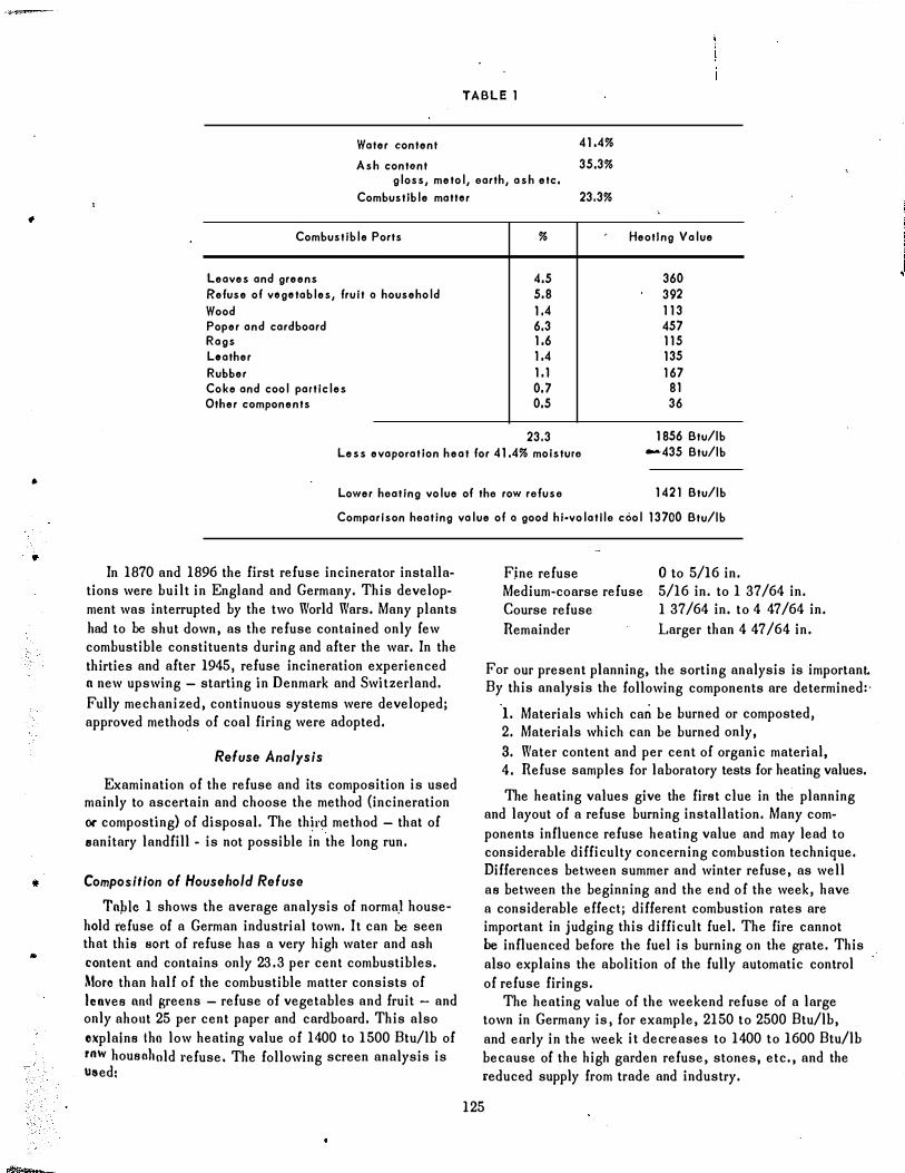
TABLE 1
Water content 41.4%
Ash contont 35.3% gloss, metol, earth, ash etc.
Combustible mattor 23.3%
Combustible Ports
Leaves and greens Refuse of vogotables, fruit 0 household Wood Poper and cardboard Rags Loather Rubber Coke and cool particles Other components
%
4.5 5.8 1.4 6.3 1.6 1.4 1.1 0.7 0.5
23.3
Heotlng Value
360 392 113 457 115 135 167
81 36
Less evaporation heat for 41.4% moisture 1856 Btu/lb
-435 Btu/lb
Lower heating volue of the row refuse 1421 Btu/lb
Comparison heating value of 0 good hi"volatlle cool 13700 Btu/lb
In 1870 and 1896 the first refuse incinerator installations were built in England and Germany. This development was interrupted by the two World Wars. Many plants had to be shut down, as the refuse contained only rew combustible constituents during and after the war. In the thirties and after 1945, refuse incineration experienced n new upswing - starting in Denmark and Switzerland. Fully mechanized, continuous systems were developed; approved methods of coal firing were adopted.
Refuse Analysis
Examination of the refuse and its composition is used mainly to ascertain and choose the method {incineration or composting} of disposal. The third method - that of .anitary landfill - is not possible in the long run.
Composition of Household Refuse
Topic 1 shows the average analysis of norma,! household refuse of a German industrial town. It can be seen that this 80rt of refuse has a very high water and ash content and contains only 23. 3 per cent combustibles. Mor. than hall of the combustible matter consists of leaves ond greens - refuse of vegetables and fruit - and only ahollt 25 per cent paper and cardboard. This also oxplalns tho low heating value of 1400 to 1500 Btu/lb of raw housnllald I'efuse. The following screen analysis is used,
Fjne refuse Medium�coarse refuse Course refuse Remainder
o to 5/16 in. 5/16 in. to 1 37/64 in. 1 37/64 in. to 4 47/64 in. Larger than 4 47/64 in.
For our present planning, the sorting analysis is important. By this analysis the following components are determined,·
I. Materials which can be burned or composted, 2. Materials which can be burned only, 3. Water content and per cent of organic material, 4. Refuse samples for laboratory tests for heating values.
The heating values give the first clue in the planning and layout of a refuse burning installation. Many components influence refuse heating value and may lead to considerable difficulty concerning combustion technique. Differences between summer and winter refuse, as well as between the beginning and the end of the week, have a considerable effect; different combustion rates are important in judging this difficult fuel. The lire cannot be influenced before the fuel is burning on the grate. This also explains the abolition of the fully automatic control of refuse firings.
The heating value of the weekend refuse of a large town in Germany is, for example, 2150 to 2500 Btu/lb, and early in the week it decreases to 1400 to 1600 Btu/lb because of the high garden refuse, stones, etc., and the reduced supply from trade and industry.
125
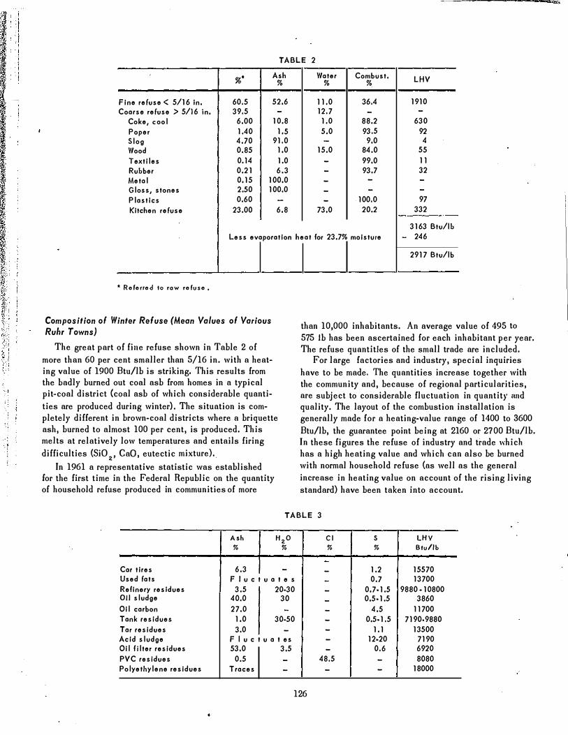
TABLE 2
%' Ash Water Combust. LHV % % %
Fine refuse < 5/16 in. 60.5 52.6 11,0 36.4 1910 Coarse refuse> 5/16 in. 39.5 - 12.7 - -
Coke, cool 6.00 10.8 1,0 88.2 630
Poper 1,40 1,5 5.0 93.5 92 Slog 4.70 91,0 - 9.0 4 Wood 0.85 1.0 15.0 84.0 55
Textiles 0.14 1.0 - 99.0 11 Rubber 0.21 6.3 - 93.7 32 Metal 0.15 100.0 - - -
Gloss, stones 2.50 100.0 - - -
Plastics 0.60 - - 100.0 97
Kitchen refuse 23.00 6.8 73.0 20.2 332
3163 Btu/lb Less evaporation heat for 23.7% moisture - 246
, ,
* Referred to raw refuse.
Composition of Winter Refuse (Mean Yalues of Yarious Ruhr Towns)
The great part of fille refuse shown in Table 2 of more than 60 per cent smaller than 5/16 in. with a heating value of 1900 Btu/lb is striking. This results from the badly burned out coal asb from homes in a typical pit-coal district {coal asb of which considerable quantities are produced during winter), The situation is completely different in brown-coal districts where a briquette ash, burned to almost 100 per cent, is produced. This melts at relatively low temperatures and entails firing difficulties (SiOz' CaD, eutectic mixture).
In 1961 a representative statistic was established for the first time in the Federal Republic on the quantity of household refuse produced in communities of more
2917 Btu/lb
than 10,000 inhabitants. An average value of 495 to 575 Ib has been ascertained for each inhabitant per year. The refuse quantities of the small trade are included.
For large factories and industry, special inquiries have to be made. The quantities increase together with the community and, because of regional particularities, are subject to considerable fluctuation in quantity and quality. The layout of the combustion installation is generally made for a heating-value range of 1400 to 3600 Btu/lb, the guarantee point being at 2160 or 2700 Btu/lb. In these figures the refuse of industry and trade which has a high heating value and which can also be burned with normal household refuse (as well as the general increase in heating value on account of the rising living standard) have been taken into account.
TABLE 3
Ash HzO CI S LHV % % % % Btu/lb
-
Car tires 6.3 - - 1.2 15570 Used fats F l u c t u a t e s - 0.7 13700 Refinery residues 3.5 20·30 - 0.7·1.5 9880· 10800 011 sludge 40.0 30 - 0.5·1.5 3860 Oil carbon 27.0 - - 4.5 11700 Tank residues 1.0 30·50 - 0.5·1.5 7190·9880 Tar residues 3.0 - - 1.1 13500 Acid sludge F l u c t u a t es - 12·20 7190 Oil fjlter residues 53.0 3.5 - 0.6 6920 PVC residues 0.5 - 48.5 - 8080 Polyethylene residues Traces - - - 18000
126
>----
•
•
•
•
•
Makeup of InJustrlal R.fuse
Special difficulties appear with the combustion of industrial refuse, Table 3. Peak heating values of )8,000 Btu/lb, and components such as sulphur and chlorine require special design measures for firing and
I boilcr�henling surfaces. One of the most used plastics is polyvinyl chloride (PVC); simultaneously it is the most troublesome to the refuse burning installations. Its proportion in household refuse is today between 1 and 3 per cent. The chlorine content of this material, which is dilficult to burn, is about 50 per cent, and when heated oyer 446 F, it .appears as hydrocJ.loric acid. In the combustion of PVC, one has to reckon with slagging and lube corrosion due to the formation of sodium chloride nnd direct attack by hydrochloric acid. With too low rurnace temperatures and insufficient gas combustion, PVC burns with intense soot development. The soot absorbs hydrochloric acid and produces considerable corrosion when deposited on tube walls. This is frequently observed in small plants.
The effect of burning car tires and acid sludge has olso been examined. The latter material !s produced in the refining of heavy oils and contains 12 to 20 per cent sulphur as free sulphuric acid. The combustion of this sulphur is possible in the refineries only through high capital investment; other eco-Demieal elimination or utilization is not possible. According to our observations, however, combustion is possible with a good mixture with high-asll household refuse, as a great percentage of the sulphur trioxide produced will be bound by hasic ash particles.
W�en burning tire rubber, neither slagging nor corro� sion were found in spite of the high sulphur content. 'nlis is due to the mineral softener oils in the rubber filler - zinc carbonate and zinc oxide.
As is known, both carbonates and oxides are successfully used in oil-fired boilers in order to avoid flue gas corrosion. Industrial refuse is transported separately, not togetber with normal household refuse. The effects of the various refuse components during combustion {pastes, themoplastics} and composting (toxic agents, residual materials which cannot be composted) need, as the case may be, special examination and constructive measures in the incinerator and boiler plant.
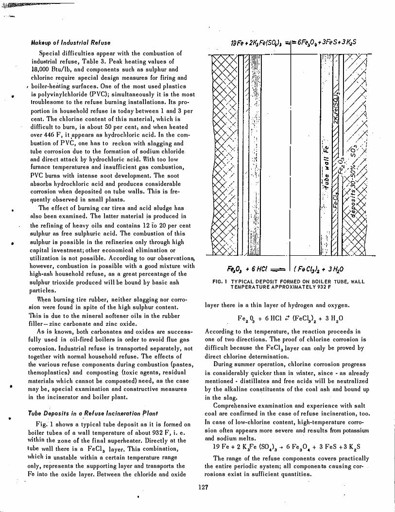
Tube Deposits in a Refuse Incineration Plant
Fig.' 1 shows a typical tube deposit as it is formed on boiler tubes of a wall temperature of about 932 F, i. e. lI,tbin the zone of the final superheater. Directly at the tube wnll there is a FeCI. layer. This combination, which is unstable within a certain temperature range only, represents the supporting layer and transports the F. into the oxide layer. Between the chloride and oxide
/
"
i �! .
i ·'1' / , " / . ,
FIG. 1 TYPtCAL DEPOSIT FORMED ON BOILER TUBE, WALL TEMPERATURE APPROXIMATELY 932 F
layer there is a thin layer of hydrogen and oxygen.
Fe2 O. + 6 HCl ;: (FeCV2 + 3 H20
According to the temperature, the reaction proceeds in one of two directions. The proof of chlorine corrosion is difficult because the FeCl31ayer can only be proved by direct chlorine determination.
During summer operation, chlorine corrosion progress is considerably quicker than in winter, since - as already mentioned - distillates and free acids will be neutralized by the alkaline constituents of the coal ash and bound up in the slag.
Comprehensive examination and experience with salt coal are confirmed in the case of refuse incineration, too . In case of low-chlorine content, high-temperature corrosion often appears more severe and results from potassium and sodium melts.
19 Fe + 2 KFe (SO.). � 6 Fe.O. + 3 FeS + 3 K2S
The range of the refuse components covers practically the entire periodic system; all componen ts causing corw rosions exist in suHicient quantities.
127
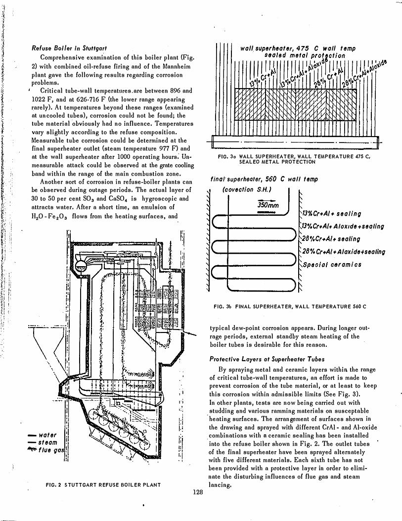
Refuse Boller In Stuttgart Comprehensive examination of this boiler plant (Fig.
2) with combined oil-refuse firing and of the Mannheim plant gave the following results regarding corrosion problems.
Critical tube-wall temperatures. are between 896 and 1022 F, and at 626-716 F (the lower range appearing rarely). At temperatures beyond these ranges (examined at un cooled tubes), corrosion could not be found; the tube material obviously had no influence. Temperatures vary slightly according to the refuse composition. Measurable tube corrosion could be determined at the final superheater outlet (steam temperature 977 F) and at the wall superheater after 1000 operating hours: Unmeasurable attack could be observed at the grate cooling band within the range of the main combustion zone.
Another sort of corrosion in refuse-boiler plants can be observed during outage periods. The actual layer of 30 to 50 per cent SO. and CaSO. is hygroscopic and attracts water. After a short time, an emulsion of H,O - Fe,O. flows from the heating surfaces, and
...
"
1'; .
i;;
- water -steam � flue
FIG. 2 S TUTTGART REFUSE BOILER PLANT
128
wall su perheater, 475 C wall temp
1III iil'jillJ!J!t[HID!lI I 1 1 �!." 'I)' ,c. \3'1.0 ��'I' ��'IP
II U
�. 'Yy '{y
FIG. 30 WALL SUPERHEATER. WALL TEMPERATURE 475 C, SEALEO METAL PROTECTION
finat superheater, 560 C wall temp
.+
� (covection S.H.)
� -
, JSOmm
IJ%Cr+AI+ sealing
IJ%Cr+A/. AlaKlde+sealing
28%Cr.A/. sealing
-
IC , ) 1'; , C I'
)� 28% Cr.AI + AlaKi de+sealing
Special cBrami cs
�C �. �
)f FIG. 3b FINAL SUPERHEATER. WALL TEMPERATURE 560 C
typical dew-point corrosion appears. During longer outrage periods, external standby steam heating of the boiler tubes is desirable for this reason.
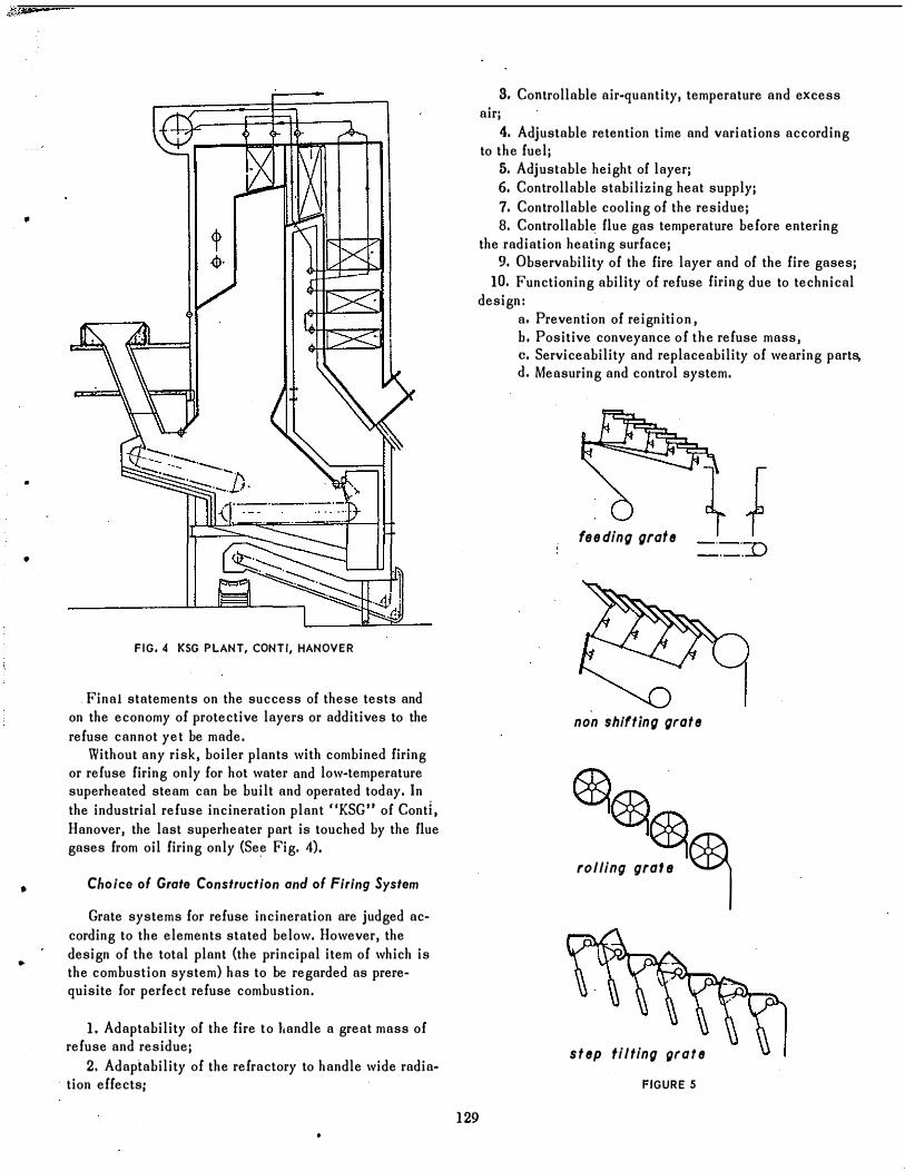
Profect/ve Layers of Superheafer Tubes
By spraying metal and ceramic layers within the range of critical tube�wall temperatures, an effort is made to prevent corrosion of the tube material, or at least to keep this corrosion within admissible limits (See Fig. 3). In- other plants, tests are now being carried out with
. studding �nd various ramming materials on susceptable heating surfaces. The arrangement of surfaces shown in the drawing and sprayed with different CrAI - and AI-oxide
. combinations with n ceramic sealing has been installed into the refuse boiler shown in Fig. 2. The outlet tubes of the final superheater have been sprayed alternately with five different materials. Each sixth tube has not been provided with a protective layer in order to eliminate the disturbing influences of flue gas and steam lancing.
•
•
•
•
•
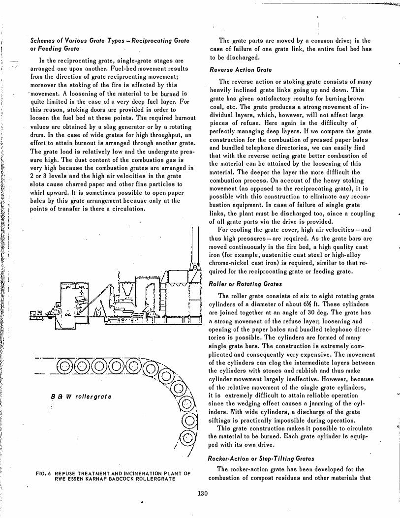
FIG. 4 KSG PLANT, CONTI, HANOVER
. Final statements on the success of these tests and on the economy of protective layers or additives to the refuse cannot yet be made.
Without any risk, boiler plants with combined firing or refuse firing only for hot water and low.temperature superheated steam can be built and operated today. In the industrial refuse incineration plant flKSG" of Conti, Hanover, the last superheater part is touched by the lIue gases from oil firing only (See Fig. 4).
Choice of Grat. Construction and of Firing System
Grate systems for refuse incineration are judged according to the elements stated below. However, the design of the total plant (the principal item of which is the combustion system) has to be regarded as prerequisite for perfect refuse combustion.
1. Adaptability of the fire to handle a great mass of refuse and residue;
2. Adaptability of the refractory to handle wide radiation effects;
s. Controllable air-quantity, temperature and excess air;
4. Adjustable retention time and variations according to the fuel;
5. Adjustable height of layer; 6. Controllable stabilizing heat supply; 7. Controllable cooling of the residue; 8. Controllable lIue gas temperature before entering
the radiation heating surface; 9. Observability of the fire layer and of the fire gases;
10. Functioning ability of refuse firing due to technical design:
a, Prevention of reignition, h. Positive conveyance of the refuse mass, c. Serviceability and replaceability of wearing parts, d. Measuring and control system.
feeding grate
non shifting grate
, ,,11/, •• "" �
step tilting grate
FIGURE 5
129
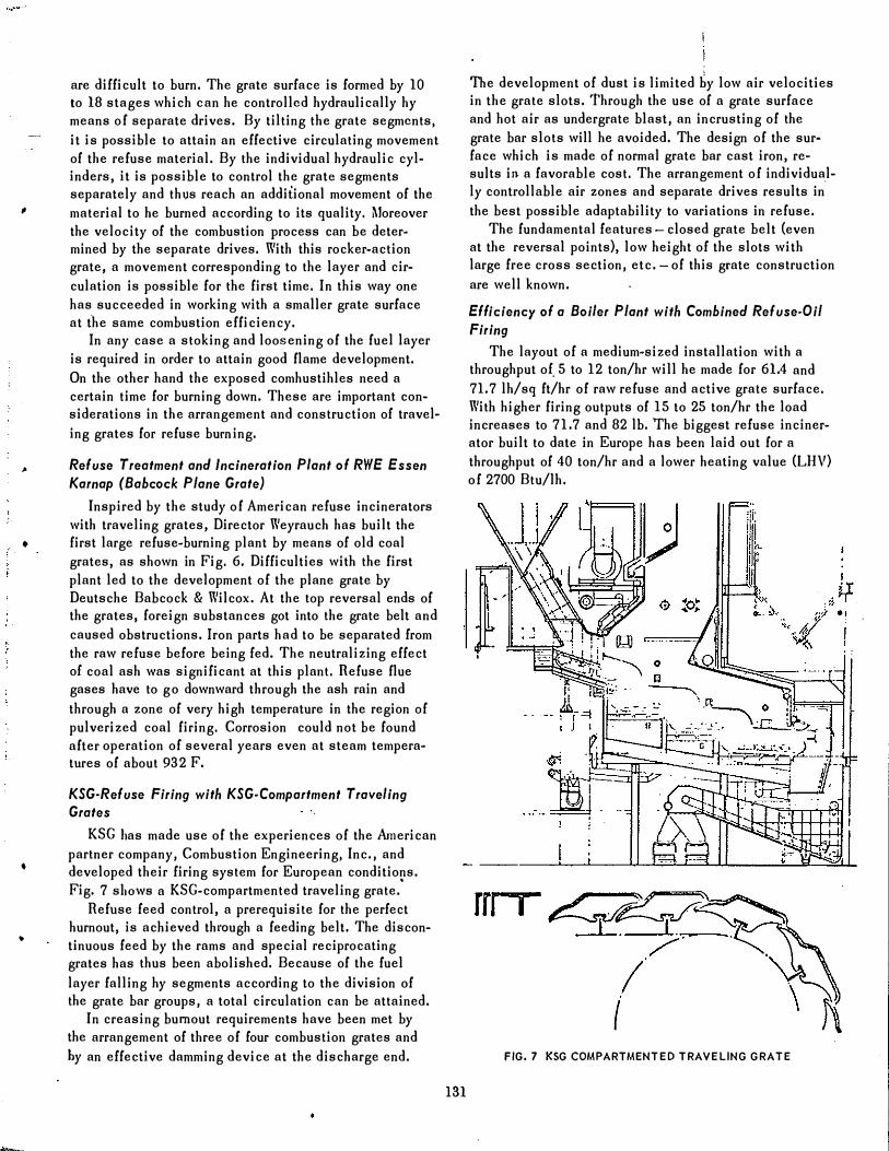
Scl,emes 0' Various Grate Types - Reciprocating Grate or Feeding Grate
In the reciprocating grate, single.grate stages are orranged one upon another. Fucl·bed movement results (rom the direction of grate reciprocating movementj moreover the stoking of the fire is effected by this
'movement. A loosening of the material to be burned is quite limited in the case of a very deep fuel layer. For this reason, stoking doors are provided in order to loosen the fuel bed a t these points. The required burnout values are obtained by a slag generator or by a rotating drum. In the case of wide grates for high throughput, an effort to attain burnout is arranged through another grate. The grate load is relatively low and the undergrate pressure high. The dust content of the combustion gas is very high because the combustion grates arc arranged in 2 or 3 levels and the high air velocities in the grate slots cause charred paper and other fine particles to whirl upward. It is sometimes possible to open paper bales by this grate arrangement because only at the points of transfer is there a circulation.
� a W rol/ergrafe
FIG. 6 REFUSE TREATMENT AND INCINERATION PLANT OF RWE ESSEN KARNAP BABCOCK ROLLERGRATE
130
--------------------------�4�·�
The grate parts are moved by a common drive; in the case of failure of one grate link, the entire fuel bed has to be discharged.
Reverse Action Grafe
The reverse action or stoking grate consists of many heavily inclined grate links going up and down. This grate has given satisfactory results for burning brown coal, etc. The gratc produces a strong movement of in· dividual layers, which, however, will not affect large pieces of refuse. Here again is the difficulty of perfectly managing deep layers. 1£ we compare the grate construction for the combustion of pressed paper bales and bundled telephone directories, we can easily find that with the reverse acting grate belter combustion of the material can be attained by the loosening of this material. The deeper the layer the more difficult the combustion process. On account of the heavy stoking movement (as opposed to the reciprocating grate), it is possible with this construction to eliminate any recombustian equipment. In case of failure of single grate links, the plant must be discharged too, since a coupling of all grate parts via the drive is provided.
For cooling the gratc cover, high air velocities - and thus high pressures - are required. As the grate bars are moved continuously in the fire bed, a high quality cast iron (for example, austenitic cast steel or high-alloy chrome-nickel cast iron) is required, similar to that required for the reciprocating grate or feeding grate.
Roller or Rotating Grates
The roller grate consists of six to eight rotating grate cylinders of a diameter of about 6l!, ft. These cylinders are joined together at an angle of 30 deg. The grate has a strong movement of the refuse layer; loosening and opening of the paper bales and bundled telephone directories is possible. The cylinders are formed of many single grate bars. The construction is extremely complicated and consequently very expensive. The movement of the cylinders can clog the intermediate layers between the cylinders with stones and rubbish and thus make cylinder movement largely ineffective. However, because of the relative movement of the single grate cylinders, it is extremely difficult to attain reliable operation since the wedging effect causes a jamming of the cylinders. With wide cylinders, a discharge of the grate siftings is practically impossible during operation.
This grate construction makes it possible to circulate the material to be burned. Each grate cylinder is equipped with its own drive.
Rocker-Action or Step. Tilting Grates
The rocker-action grate has been developed for the combustion of compost residues and other materials that
•
•
•
•
•
�-
are difficult to burn. The grate surface is formed by 10 to 18 stages which ean he controlled hydraulically hy means of separate drives. By tilting the grate segments, it is possible to attain an effective circulating movement of the refuse material. By the individual hydraulic cylinders, it is possible to control the gratc segments separately and thus reach an additional movement of the material to he burned according to its quality. Moreover the velocity of the combustion process can be deter� mined by the separate drives. With this rocker-action grate, a movement corresponding to the layer and circulation is possible for the first time. In this way one has succeeded in working with a smaller grate surface at t"he same combustion efficiency.
In any case a stoking and loosening of the fuel layer is required in order to attain good flame development. On the other hand the exposed comhustihles need a certain time for burning down. These arc important considerations in the arrangement and construction of traveling grates for refuse burning.
Refuse Treatment and Incineration Plant of RWE Essen Karnap (Babcock Plane Grate)
Inspired by the study of American refuse incinerators with traveling grates, Director Weyrauch has built the first large refuse-burning plant by means of old coal grates, as shown in Fig. 6. Difficulties with the first plant led to the development of the plane grate by Deutsche Babcock & Wilcox. At the top reversal ends of the grates, foreign substances got into the grate belt and caused obstructions. Iron parts had to be separated from the raw refuse before being fed. The neutralizing effect of coal ash was significant at this plant. Refuse flue gases have to go downward through the ash rain and through a zone of very high temperature in the region of pulverized coal firing. Corrosion could not be found after operation of several years even at steam temperatUres of about 932 F.
KSG·Refuse Firing with KSG·Compartment Traveling Grates
KSG Jlas made use of the experiences of the American partner company, Combustion Engineering, Inc., and developed their firing system for European conditions. Fig. 7 sllOws a KSG-compartmented traveling grate.
'
Refuse feed control, a prerequisite for the perfect hurnout, is achieved thl'Ough a feeding belt. The discontinuous feed by the rams and special reciprocating grates has thus been abolished. Because of the fuel layer falling hy segments according to the division of the grate bar groups, a total circulation can be attained.
In creasing burnout requirements have been met by the arrangement of three of four combustion grates and hy an effective damming device at the discharge end.
131
The development of dust is limited by low air velocities in the grate slots. Through the use of a grate surface and hot air as undergrate blast, an incrusting of the grate bar slots will he avoided. The design of the surface which is made of normal grate bar cast iron, results in a favorable cost. The arrangement of individually controllable air zones and separate drives results in
"
the best possible adaptability to variations in refuse. The fundamental features - closed grate belt (even
at the reversal points), low height of the slots with large free cross section, etc. - of this grate construction are well known.
Efficiency of a Boiler Plant with Combined Refuse-Oil Firing
The layout of a medium-sized installation with a throughput of. 5 to 12 ton/hr will he made for 61.4 and 71.7 Ih/sq ft/hr of raw refuse and active grate surface. With higher firing outputs of 15 to 25 ton/hr the load increases to 71.7 and 82 lb. The biggest refuse incinerator built to date in Europe has been laid out for a throughput of 40 ton/hr and a lower heating value (LHV) of 2700 Btu/lh.
rn I
FIG. 7 KSG COMPARTMENTED TRAVELING GRATE

The refuse throughput at heating values which are higher than the guaranteed value is limited by the maximum gross heating value. The layout will be made for a refuse heating value of 2160 or 2700 Btullb at a maximum thermal load of the grate of about 300,000 Btu/sq ft/hr.
.
The efficiency diagrams shown in Fig. 8 are valid for a radiant boiler wi tl1 combined refuse�oil firing for a steam output of 110,000 lblhr at 600 psi and 536 F. The refuse burning capacity is 15 tonlhr at 600 psi and 536 F. The refuse hurning capacity is 15 tonlhr at a refuse heating value (LHV) of 1400 to 3600 Btu/lb. The boiler plant can be operated with refuse only as well as with oil only, or combined in any ratio. The total efficiency results from a combination of the refuse firing efficiencies shown below, depending on the heating value and on the upper efficienc), line for oil firing. Steam output can be detcrmined with refuse firing depending on the heating value and on the upper efficiency line for oil firing. Steam output can also be determined with the refuse firing alone.
�. efficiency
90i----�--�--�----4---_+
OO+-----+-----+-----�----���
960e�.--- -.. ... -
. 50-1--1--4-+-+-+--11--+--+--1-+ o 20 40 60 100
% slsam flow
FIG.8 EF FICIENCY DIAGRAMS FOR RADIANT BOILER WITH COMBINED REFUSE·OIL FIRING FOR STEAM OUTPUT OF 110,000 Ib/}" AT 600 p,1 AND 536 F
132
�. ,.... I . -·tf.'· .. ·
FIG. 9 VOLUND INCINERATOR DESIGN
The furnace loads range between 16,900 and 22,500 Btulcu ft/hr. The radiant chamber of the boiler plant will be laid out for a heating surface load of 40,500 to 110,000 Btulsq ftlhr and a cross-section load of 500,000 to 700,000 Btu/sq ft/hr.
"Volunc/II Incinerator Design
This system (See Fig. 9) has a feeding and drying grate as well as a combustion grate (both grates being designed as reciprocating grates) and a rotary kiln for burnout. Some disadvantages of this firing technique are: the gas path is not well-defined, it is difficult to bring sufficient oxygen to the combustible parts in the rotating kiln at slightest excess air, and there is a relatively high space requirement. Also, the combustion gases may choose their route to the waste�heat boiler via the preliminary drying chamber and the by-pass duct or through the kiln.
The space required has been reduced by arranging the feed grate and the drying grate in opposite directions above the drum. However, a considerable height of fuel
•
.\ I
•
•
•
•
•
F.D. Fan
Tangential Air Feed ....
Axial Air
, ' . . . . . . . . . . . . . . . . . . . . . . . . . . . . .
FluB ·Gas
Air Channel
FIG. 10 COM BUSTION DRUM
r,11
, o
FIG. 11 VON ROLL SYSTEM BUILT FOR FRANKFURT PLANT
lall is required, because of a rising flue-gas £low and an increased delivery head. The connection to a waste heat boiler still remains a problem.
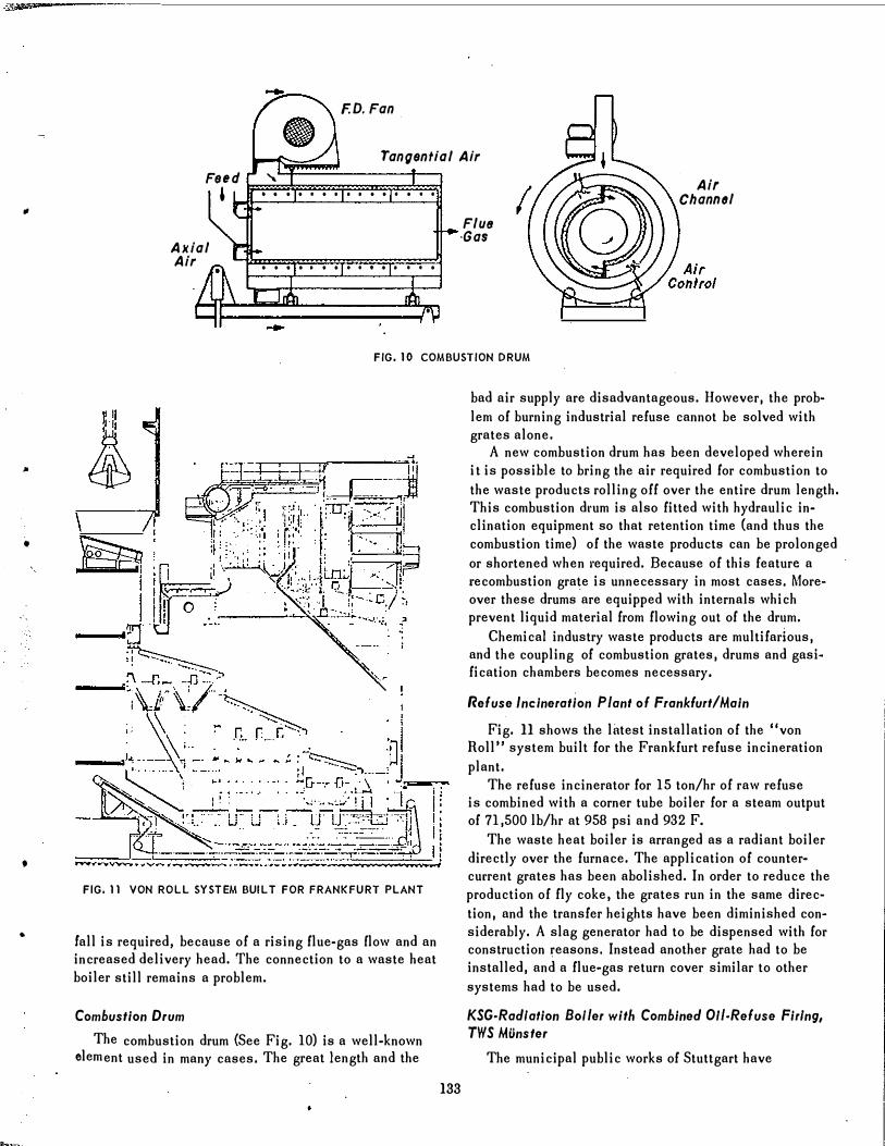
Combustion Drum
The combustion drum (See Fig. 10) is a well-known element used in many cases. The great length and the
133
bad air supply are disadvantageous. However, the problem of burning industrial refuse cannot be solved with grates alone.
A new combustion drum has been developed wherein it is possible to bring the air required for combustion to the waste products rolling off over the entire drum length. This combustion d"um is also fitted with hydraulic inclination equipment so that retention time (and thus the combustion time) of the waste products can be prolonged or shortened when l·equired. Because of this feature a recombustion grate is unnecessary in most cases, Moreover these drums are equipped with internals which prevent liquid material from flowing out of the drum.
Chemical industry waste products are multifarious, and the coupling of combustion grates, drums and gasi .. fication chambers becomes necessary.
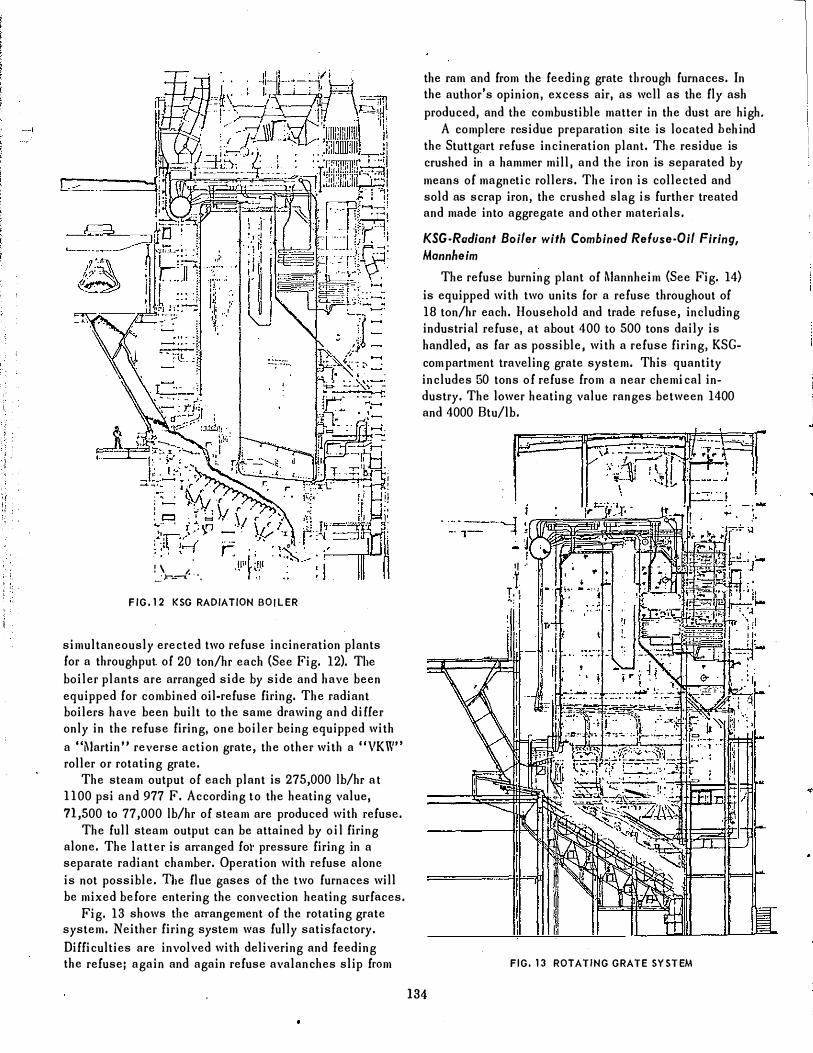
nefuse Incineration Plant of Frankfurt/Main
Fig. 11 shows the latest installation of the "von Roll" system built for the Frankfurt refuse incineration plant.
The refuse incinerator for 15 ton/hr of raw refuse is combined with a corner tube boiler for a steam output of 71,500 Ib/hr at 958 psi and 932 F.
The waste heat boiler is arranged as a radiant boiler directly over the furnace. The application of countercurrent grates has been abolished. In order to reduce the production of fly coke, the grates run in the same direction, and the transfer heights have been diminished considerably. A slag generator had to be dispensed with for construction �easons. Instead another grate had to be installed, and a flue-gas return cover similar to other systems had to be used.
KSG-Radlafion Boller with Combined OIl·Refuse FirIng, TWS MOnsfer
The municipal public works of Stuttgart have
; , .
r: " '\ ,tlll/.;',"," �r.:-f " , f
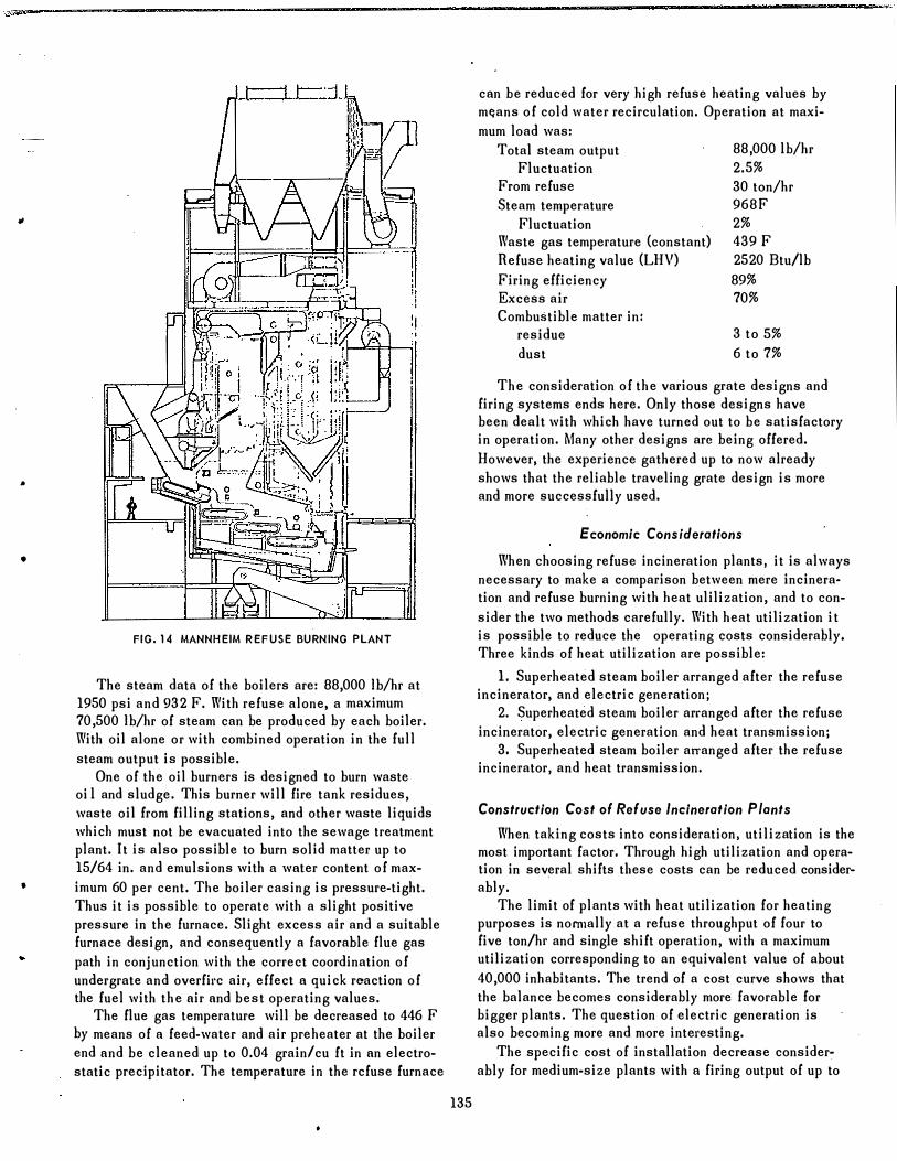
FIG.12 KSG RADIATION BOILER
simultaneously erected two refuse incineration plants for a throughput of 20 ton/hr each (See Fig. 12). TIle boiler plants are arranged side by side and have been equipped for combined oil-refuse firing. The radiant boilers have been built to the same drawing and di££er only in the refuse firing, one boiler being equipped with a "�JartinU reverse action grate, the other with a "VKW" roller or rotating grate.
The steam output of each plant is 275,000 Ib/hr at 1100 psi and 977 F. According to the heating value, n,500 to 77,000 Ib/hr of steam are produced with refuse.
The full steam output can be attained by oil firing alone. The latter is arranged fo1' pressure firing in a separate radiant chamber. Operation with refuse alonc is not possible. The flue gases of the two furnaces will be mixed before entering the convection heating surfaces.
Fig. 13 shows t11c arrangement of the rotating grate system. Neither firing system was fully satisfactory. Difficulties are involved with delivering and feeding the refuse; again and again refuse avalanches slip fL'Om
the ram and from the feeding grate tllfough furnaces. In the author's opinion, excess air, as well as the fly ash produced, and the combustible matter in the dust are high.
A complcrc rcsidue preparation site is located hchind thc Stuttg�rt refuse incincration plant. The residue is crushed in a hammer mill, and the iron is separated by meanS of magnctic rollers. The iron is collected and sold as scrap iron, the crushed slag is further treated and made into aggregate and other materials.
KSG-Rudiant Boiler with Combined Refuse-Oil Firing, Mannheim
The refuse burning plant of Mannheim (See Fig. 14) is equipped with two units for a refuse throughout of 18 ton/hr each. Household and trade refuse, including industrial refuse, at about 400 to 500 tons daily is handled, as far as possible, with a refuse firing, KSGcompartment traveling grate system. This quantity includes 50 tons of refuse from a near chemi cal industry. The lower heating value ranges between 1400 and 4000 Btu/lb.
'I··
1 � I
J
FIG. 13 ROTATING GRATE SYSTEM
134
, :
. "
" ,
;"
�W· __ ---------------- ______________________________________________________________ _
•
•
•
•
FIG. 14 MANNHEIM REFUSE BURNING PLANT
The steam data of the boilers are: 88,000 Iblhr at 1950 psi and 932 F. With refuse alone, a maximum 70,500 Iblhr of steam can be produced by each boiler. With oil alone or with combined operation in the full steam output is possible.
One of the oil burners is designed to burn waste oi I and sludge. This burner will fire tank residues, waste oil from filling stations, and other waste liquids whicJl must not be evacuated into the sewage treatment plant. It is also possible to burn solid matter up to 15/64 in. and emulsions with a water content of maximum 60 per cent. The boiler casing is pressure-tight. Thus it is possible to operate with a slight positive pressure in the furnace. Slight excess air and a suitable furnace design, and consequently a favorable flue gas path in conjunction with the correct coordination of undergrate and overfil'c air, effect a quick reaction of the fuel with the nil' nnd best operating values.
The flue gas temperature will be decreased to 446 F by means of a feed-water and air pre heater at the boiler end nnd be cleaned up to 0.04 grain/cu ft in nn electrostatic precipitator. The temperature in the rcfuse furnace
135
can be reduced for very high refuse heating values by mf;ans of cold water recirculation. Operation at maximum load was:
Total steam output Fluctuation
From refuse Steam temperature
Fluctuation Waste gas temperature (constant) Refuse heating value (LHV) Firing efficiency Excess air Combustible matter in:
residue dust
88,000 Iblhr 2.5% 30 tonlhr 968F 2% 439 F 2520 Btu/lb 89% 70%
3 to 5% 6 to 7%
The consideration of the various grate designs and firing systems ends here. Only those designs have been dealt with which have turned out to be satisfactory in operation. Many other designs arc being offered. However, the experience gathered up to now already shows that the reliable traveling grate design is more and more successfully used.
Economic Considerations
When choosing refuse incineration plants, it is always necessary to make a comparison between mere incineration and refuse burning with heat ulilization, and to consider the two methods carefully. With heat utilization it is possible to reduce the operating costs considerably. Three kinds of heat utilization are possible:
1. Superheated steam boiler arranged after the refuse incinerator, and electric generation;
2. Superheated steam boiler arranged after the refuse incinerator, electric generation and heat transmission;
3. Superheated steam boiler arranged after the refuse incinerator, and heat transmission.
Construction Cost of Refuse Incineration Plants
When taking costs into consideration, utilization is the most important factor. Through high utilization and operation in sev.eral shifts tl1ese costs can be reduced considerably.
The limit of plants with heat utilization for heating purposes is nomlUlly at a refuse throughput of four to five ton/hI' and single shift operation, with a maximum utilization corresponding to an equivalent value of about 40,000 inhabitants. The trend of a cost curve shows that the balance becomes considerably more favorable for higger plants. The question of electric generation is also becoming more and more intel·esting.
The specific cost of installation decrease considerably for medium-size plants with a firing output of up to
� ! � 1
i >
(
I
I � t I � i
t y.' � �. t �
I t l: r 11 � . 1 , i: f, ! n , , ; ! � 1 "
•
10 ton/hr. With big plants with an output of more than 15 ton/hr the cost per ton of refuse remains practically constant.
For plants with heat utilization, the erection of a reserve unit can hardly be avoided as the fuel always changes even with fully developed designs so that absolute availability cannot be guaranteed.
Operating Costs a( Re(use Incineration Plant.
The operating costs of refuse incineration plants as specific costs per ton of burned refuse include capital costs, personnel costs, electrical costs, water costs, repair and maintenance costs, and overhead expenses.
They are based on an operating life of 20 years for the equipment and installation, of 50 years for the buildings and on an interest of 6.5 per cent. Operating costs are based on full-load capacity; for part-load operation these costs are less favorable.
Refuse conveyor costs are not included, nor are the residue removal costs which, at an ash content of 40 per cent, are relatively high.
Incineration plants without heat utilization should only be huilt in sizes of hetween five and eight ton/hr of refuse. With outputs of more than 10 ton/hr, heat utilization should always he incorporated. The large flue-gas quantities should he cooled in hoiler plants and their volume should he reduced in order not to exceed an inlet temperature of 482 F into the flue-gas cleaning equipment.
It is not possible to make a general statement on the installation size which is most suitable for the various requirements. This must be examined separately in each case.
From the comparison it is to he seen that profitability is heavily influenced by:
1. Installation cost, 2. Hours of use, 3. Sale price for steam and electricity generated.
Laws (or Keeping the Air Clean and
Special Construction lor Dust Collector.
In Germany general regulations for industrial application were issued on September 8, 1964 as "Technische Anleitung zur Reinhaltung der Luft" ("Technical Instructions for Air Pollution Control"). Other European countries have partly accepted these regulations or followed the example through similar legislation.
Approval for the erection of new plants may, in principle, only be given when:
1. The plants will be equipped with equipment for the limitation and distribution of stack emission cOlTesponding to the latest state of the art;
30
I� Co
� .18
I o 20 40 60 80
';' , (flu/! !JQS I
!�, r-.....
�r ............ t--=: 80
60 .......
40 r-----." l-
20
o
136
i I I
10 20 30 40 50 grain oi." from two plant.
FIGURE 15
60" grain siz£'
2. The emission limiting values in the effective area of the plant will not be exceeded hy actual operation.
In the case of sulphur dioxide emissions of more than 441 lh/hr, it can he required to provide space for the installation of waste gas desulphurization equipment.
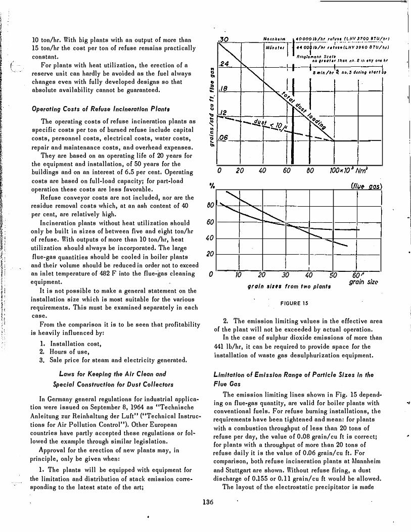
Limitation 0/ Emission Range o( Particle Sizes In the Flue Gas
The emission limiting lines shown in Fig. 15 depending on flue-gas quantity, are valid for boiler plants with conventional fuels. For refuse burning installations, the requirements have heen tightened and mean: for plants with a comhustion throughput of less than 20 tons of refuse per day, the value of 0.08 grain/cu ft is correct; for plants with a throughput of more than 20 tons of refuse daily it is the value of 0.06 grain/cu ft. For comparison, both refuse incineration plants at Mnnnheim and Stuttgart are shown. Without refuse firing, a dust discharge of 0.155 or 0. 11 grain/cu ft would be allowed.
The layout of the electrostatic precipitator is made
- iLl
•
•
."""-
TABLE 4
Annual Average Monthly Average
Non"toxlc dusts 0.6 9roin/sq ft day 0.93 groin/sq ft day
1.86 groln/sq It day In Industrial agglomeration districts 1.2 groln/sq h day
Nitrous gasos
Chlorine
Hydrogen .ulphlde
Sulphur dioxide
0.4· 10" groin NO, leu It air
0.03 graln/ �'2 hour
within 8 hours
0.12 '10" groin Clleu It air
0.009 groin Il'2 hour
within 8 hour.
0.06 '10" groin H,5/eu It air
0.0046 gralnlYo hour
within 8 hours
0.16'10" groin 50,Ieu It air
0.011 groin I Yo hour
within 2 hours
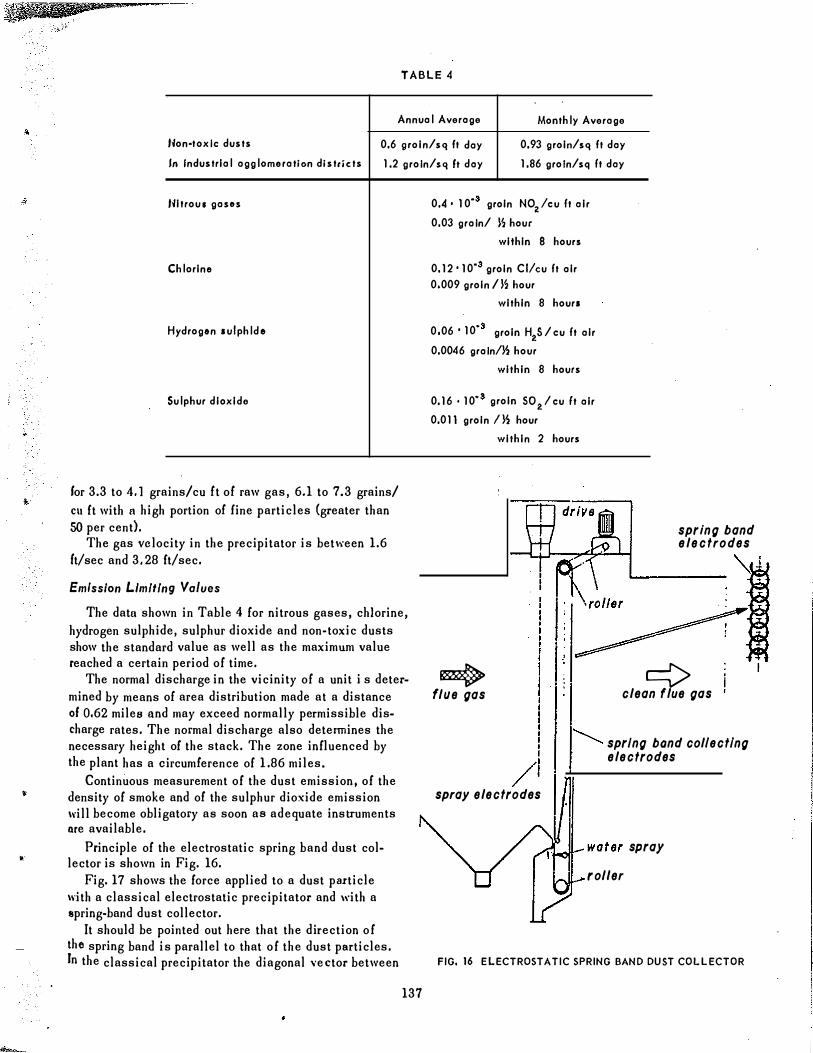
lor 3.3 to 4.1 grains/cu tt ot raw gas, 6.1 to 7.3 grains/ ell It with a high portion ot line particles (greater than 50 per cent).
The gas velocity in the precipitator is between 1.6 It/sec and 3.28 It/sec.
spring band electrodes
Emission Limiting Values
The datu shown in Table 4 for nitrous gases, chlorine, hydrogen sulphide, sulphur dioxide and non·toxic dusts show the standard value as well as the maximum value reached a certain period of time.
The normal discharge in the vicinity of a unit i s determined by means of area distribution made at a distance 010.62 miles and may exceed normally permissible discharge rates. The normal discharge also determines the necessary height of the stack. The zone influenced by the plant has a circumterence of 1.86 miles.
Continuous measurement of the dust emission, of the density of smoke and ot the sulphur dioxide emission will become obligatory as soon as adequate instruments are available.
Principle of the electrostatic spring band dust col· lector is shown in Fig. 16 .
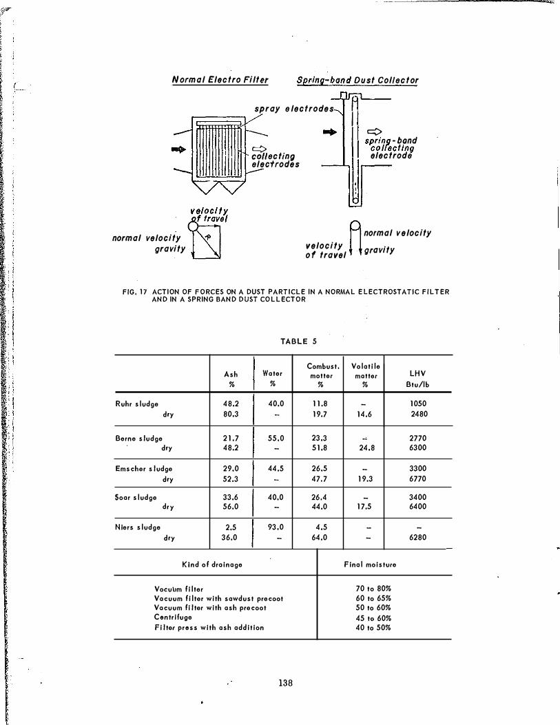
Fig. 17 shows the force applied to a dust particle with a classical electrostatic precipitator and with a spring.band dust collector.
It should be pointed out here that the direction of the spring band is parallel to that of the dust particles. In the classical precipitator the diagonal vector between
137
* flue gas
/
L--__ _
�l
¢ clean flue gas
spring bond col/ectlng electrodes
spray electrodes
...... ,-JI-_water spray
rol/er
FIG. 16 ELECTROSTATIC SPRING BAND DUST COLLECTOR
: ; , I I
" ! : !
"
Normal Electro Filter Spring-band Dust Col/ector
spray electrodes
II velocity.
bY normal velocity .p gravity
�ectln(J electrodes
c:::> spring - bond
colfeellng electrode
A normal velocity velocity � � gravity of travel
FIG. 17 ACTION OF FORCES ON A DUST PARTICLE IN A NORMAL ELECTROSTATIC FILTER AND IN A SPRING BAND DUST COLLECTOR
TABLE 5
Combust. Volatile Ash Water motter matter LHV
% % % % Btu/lb
Ruhr sludge 48.2 40.0 11.8 - 1050
d,y 80.3 - 19.7 14.6 2480
Berne sludge 21.7 55.0 23.3 - 2770 d,y 48.2 - 51.8 24.8 6300
Emscher sludge 29.0 44.5 26.5 - 3300
d,y 52.3 - 47.7 19.3 6770
Soar sludge 33.6 40.0 26.4 - 3400 d,y 56.0 - 44.0 17.5 6400
Nlers sludge 2.5 93.0 4.5 - -
d,y 36.0 - 64.0 - 6280
Kind of drainage Final moisture
VoculJm filter 70 to 80% Vacuum filter with sawdust precool 60 to 65% Vacuum filter with ash precool 50 to 60% Centrifuge 451060% Filter press with ash addition 40 to 50%
138
• I
•
•
•
•
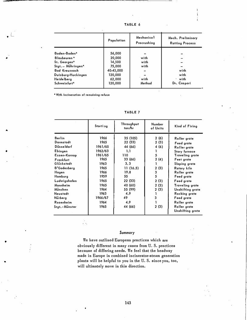
TABLE 6
Mechonico 1 Mach. Preliminary Population
Precrushing Rotting Process
Boden·Boden* 56,000 - -
Blaubeuren ,. 20,000 with -St. Georgen* 14,500 with -
Slgt. - Mohringen* 75,000 with -
Bad Kreu:z:nach 40·45,000 - with Dul sburg·Huckingen 120,000 - with Heidelberg 62,000 with with Schweinfurt* 120,000 Method Dr. Cas peri
,. With Incineration of remaining refuse
Berlin Darmstadt Dusseldorf Ehingen Essen·Kornop Frankfurt Glu'ckstadt B'Godesberg Hagen Homburg Ludwigshafen Monnheim Munchon Neustadt Nutberg Rosenheim Stgt. - Munster
TABLE 7
Storti 09 Throughput Number Kind of Firing
ton/hr of Units
1966 35 (105) 2 (6) Roller grate 1965 22 (33) 2 (3) Feed grate
1961/65 44 (66) 4 (6) Roller grate 1962/63 1.1 1 Story furnace 1961/65 110 5 Traveling grote
1965 33 (66) 2 (4) Feet grate 1963 3. 3 1 Sloping grate 1965 11 (16.5) 2 (3) Rotary kiln 1966 19.8 3 Roller grate 1959 55 5 feed grate 1965 22 (33) 2 (3) Feed grate 1965 40 (60) 2 (3) Traveling grate 1964 55 (99) 2 (3) Unshifting grate 1963 4.9 1 Rocking grate
1966/67 49 3 Feed grate 1964 4.9 1 Roller grate 1965 44 (66) 2 (3) Roller grate
Unshifting grate
Summary
We have outlined European practices which are obviously different in many cases from U. S. practices because of differing needs. We feel that the headway made in Europe in combined incinerator-steam generation plants will be helpful to you in the U. S. since you, too, will ultimately move in this direction.
143