eup lot 30: electric motors and drives€¦ · electric motors and drives task 7: improvement...
TRANSCRIPT
EuP Lot 30: Electric Motors and Drives
Task 7: Improvement Potential
ENER/C3/413-2010
June 2014
Final
Anibal De Almeida
Hugh Falkner
João Fong
2
Contents 3 Task 7: Policy and Impact Analysis ................................................................................................. 3
3.1 Options .................................................................................................................................... 3
3.2 Basis of analysis for the different products ............................................................................ 3
3.2.1 Induction Motors ............................................................................................................ 3
3.2.2 Variable Speed Drives ..................................................................................................... 4
3.2.3 Submersible Motors ........................................................................................................ 4
3.2.4 Motor + Controllers ........................................................................................................ 4
3.3 Impacts .................................................................................................................................... 6
3.3.1 Key assumptions underpinning environmental impacts ................................................ 6
3.3.2 Environmental impact of improved technology ............................................................. 7
3.4 Costs ........................................................................................................................................ 9
3.5 Analysis LLCC and BAT ............................................................................................................. 9
3.5.1 Ranking of the Design options ........................................................................................ 9
3.5.2 Analysis of indirect impacts of the individual design option ........................................ 12
3.5.3 Impact of cumulative design options – comparison of Net energy savings for each
option 13
3.6 Long-term targets (BNAT) and systems analysis ................................................................... 14
3.6.1 Long term potential of new products ........................................................................... 14
3.6.2 Long term changes in application of motors ................................................................ 15
3.7 Conclusions ........................................................................................................................... 16
3
7 Task 7: Policy and Impact Analysis
7.1 Options
This subtask identifies and describes the individual design options for environmental improvement,
based on the preceding technical analysis in Task 6.
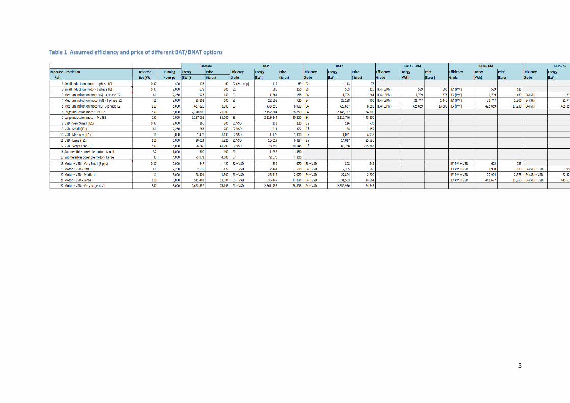
The design options for each of the basecases are presented in Task 6, and are summarised in Table 1.
This table presents each basecase and the related Best Available Technology options (efficiency and
price) for each. It is these different design options that form the basis of the analysis in this section.
7.2 Basis of analysis for the different products
7.2.1 Induction Motors
The efficiencies in this category are taken from the IE classification scheme (IEC60034-30), for 4 pole
50Hz motors. The prices are best estimates from limited available information. An increase of 10%
in stock has been assumed to account for the Brake and Explosion proof motors that were explicitly
excluded from current regulation 640/2009. In all cases the frame size dimensions are kept the
same, although a longer stack is allowed where needed.
NB. Strictly this category should be considered to be “Any line start and run single speed motor”,
but the existing nomenclature is used as it matches closely the existing regulation 640/2009.
For the Small induction motors, 3 phase <0.75kW that are not currently subject to regulation, the
basecase is assumed to be IE1, with IE2 & IE3 shown as options using conventional technology. In
addition, a LSPM motor is shown as BAT3, although any product that is line start and run could in
theory be used as an alternative to an induction motor. It is acknowledged that there are technical
differences which mean that they are not always a direct replacement, but this factor is not critical
for this analysis. For small induction motors, 1 phase < 0.75kW, IE1 is also the assumed basecase.
Two options are shown for improved performance: Addition of a second capacitor to create a
Capacitor Start Capacitor Run motor (BAT1), and additional material (conventional technology) as
BAT2.
For the Medium induction motors, IE2 is the assumed basecase, as this power range (0.75 to
375kW) is already regulated with IE2 as the MEPS. BAT options include achieving IE3 and IE4 with
conventional technology, and also reaching IE4 with an LSPM.
Large induction motors >375kW are currently not regulated, but it is believed that they are typically
at IE2 efficiency. BAT1 is therefore the IE3 level, assumed to be achieved with conventional
induction motor technology. BAT2 and BAT3 represent higher efficiencies achieved through the use
of already available technologies.
4
7.2.2 Variable Speed Drives
The Variable Speed Drives considered in the study are based on PWM inverters for induction motors,
but are considered representative of controllers for all types of motor considered. This is
reasonable on the basis that many VSDs are actually able to control many different types of motor.
There is an advanced draft CENELEC Standard 50598-2 (to be finalized by the end of 2014) that
proposes IE levels for VSD performance.,. In particular the baseline efficiency level for VSDs has
been defined as the IE1 levels.
Little information is available on the standby power losses within VSDs, and so this is something that
should be considered separately.
NB. “BAT1” is actually the industry norm, and so this is used as the basis of comparison of improved
technologies. The Basecase data given represents the most energy intensive products sold, with the
additional energy relating largely to additional functions included in the VSD package. It is the
removal of the basecase that is one of the Policy Options considered.
7.2.3 Submersible Motors
These are analyzed here in order to provide data for their possible inclusion in an Extended Product
Regulation under the LOT29 study on clean water pumps. The only option shown is for an improved
conventional induction motor. Some are supplied with VSDs, but this will be accounted for within
the Extended Product Model being developed as part of LOT29.
7.2.4 Motor + Controllers
In each case it is assumed that the improvement in efficiency is due to the use of a more efficient
motor, both because this is easily quantifiable and the savings from improved VSDs are extremely
modest. The total energy consumption takes account of the losses in the motor and VSD, and
includes an increase in the motor losses due to the harmonic content of the waveform. BAT options
are shown for a conventional IE4 motor, Permanent Magnet and Synchronous reluctance motor.
Analysis of the different technologies is relative to the use of an IE3 motor and basecase VSD. Later
in this Task, separate analysis is shown that identifies the payback of new types of variable speed
motors such as Permanent Magnet and Synchronous Reluctance.
Table 1 shows the key price and energy consumption inputs used in this analysis:
5
Table 1 Assumed efficiency and price of different BAT/BNAT options
6
7.3 Impacts
7.3.1 Key assumptions underpinning environmental impacts
For the motors considered in this study, it was previously shown in Task 5 that it is the energy
consumption that dominated environmental emissions, and so is the focus of the analysis in this
section. In the absence of firm data on the non energy environmental impact of improved induction
motors, the following assumptions have been made:
Production phase. A nominal 20% increase of materials has been assumed for an increase
of one IE level.
Distribution. The distance and the packaged volume are assumed to be the same, as often
the design will comprise a longer stack of active materials within the same casing.
Maintenance. More efficient motors run cooler and so may have a longer time between
maintenance, but this is a modest effect and so is not taken account of.
Disposal. This is assumed to be the same.
If any of these parameters are found at a later stage to be important, further analysis can be
undertaken to refine this data, but from Task 5 analysis it is clear that over the lifetime,
material content is much less significant than the energy consumption.
The use of Permanent Magnet rare earth technology is the most important difference in
terms of material use, and so this is also considered as an option. However, it should also be
noted that the business models for the use of these motors assume the reclamation of this
material, and so in reality the environmental impact of these is spread in time over a large
number of motors.
7
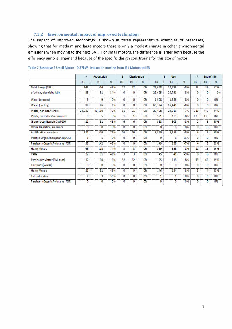
7.3.2 Environmental impact of improved technology
The impact of improved technology is shown in three representative examples of basecases,
showing that for medium and large motors there is only a modest change in other environmental
emissions when moving to the next BAT. For small motors, the difference is larger both because the
efficiency jump is larger and because of the specific design constraints for this size of motor.
Table 2 Basecase 2 Small Motor - 0.37kW- Impact on moving from IE1 Motors to IE3
8
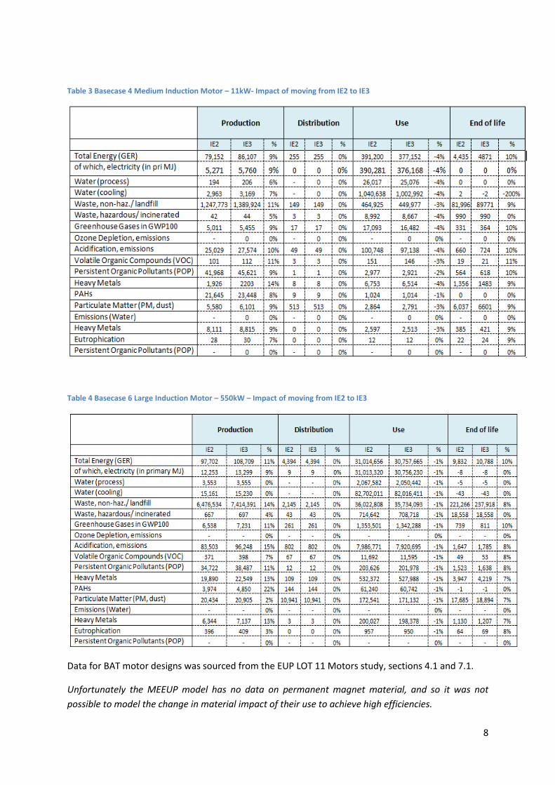
Table 3 Basecase 4 Medium Induction Motor – 11kW- Impact of moving from IE2 to IE3
Table 4 Basecase 6 Large Induction Motor – 550kW – Impact of moving from IE2 to IE3
Data for BAT motor designs was sourced from the EUP LOT 11 Motors study, sections 4.1 and 7.1.
Unfortunately the MEEUP model has no data on permanent magnet material, and so it was not
possible to model the change in material impact of their use to achieve high efficiencies.
9
7.4 Costs
For each design option, the additional cost has been estimated on the basis of incremental cost
relative to the basecase price. See Table 1 for the assumed price of each option.
7.5 Analysis LLCC and BAT
7.5.1 Ranking of the Design options
Methodology for calculation of LLCC
For each design option (BAT), a whole Life Cycle Costing (LCC) is calculated, which sums the following
factors;
Purchase price
+ Installation price
+ Maintenance price
+ Lifetime energy use
As expected for commercial motors, in each case the lifetime energy use was found to dominate the
LCC.
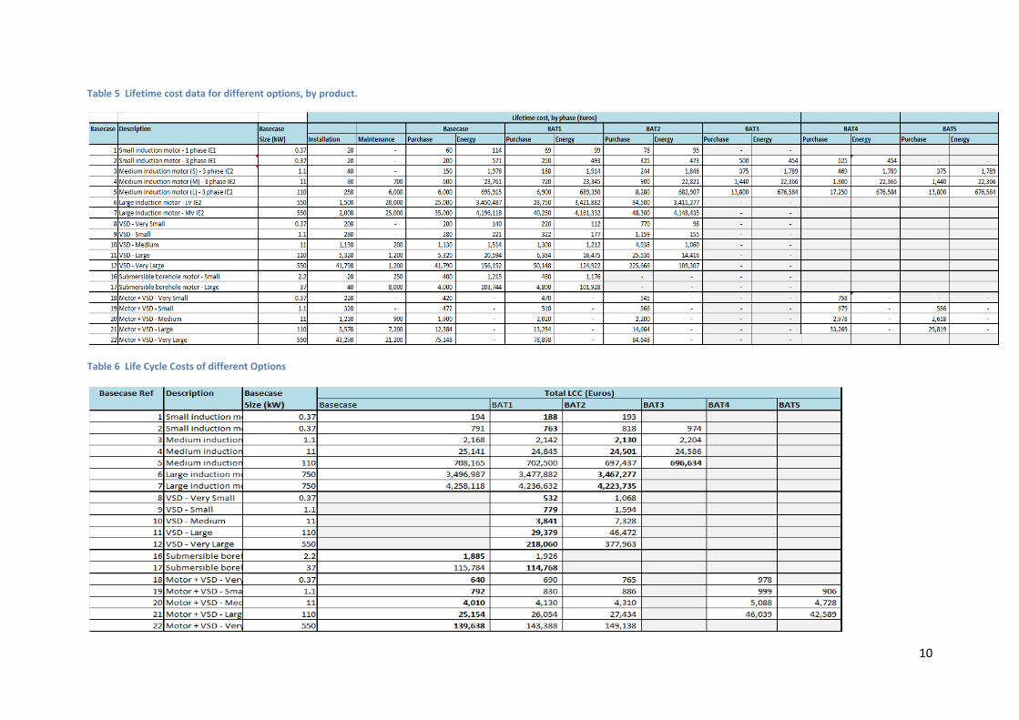
The LCC for each BAT was compared in order to identify the Lease Life Cycle Cost (LLCC) option,
which represents the best purchase option for the motor user (consumer). The breakdown of costs
are summarized in Table 5 and 6. Table 6 and Figure 1 show the total Lifecycle costs of each, with
the LLCC option shown in bold, ( Figure 1).
10
Table 5 Lifetime cost data for different options, by product.
Table 6 Life Cycle Costs of different Options
11
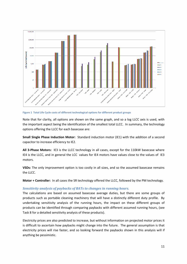
Figure 1 Total Life Cycle costs of different technological options for different product groups
Note that for clarity, all options are shown on the same graph, and so a log LLCC axis is used, with
the important aspect being the identification of the smallest total LLCC. In summary, the technology
options offering the LLCC for each basecase are:
Small Single Phase Induction Motor: Standard induction motor (IE1) with the addition of a second
capacitor to increase efficiency to IE2.
All 3-Phase Motors: IE3 is the LLCC technology in all cases, except for the 110kW basecase where
IE4 is the LLCC, and in general the LCC values for IE4 motors have values close to the values of IE3
motors.
VSDs: The only improvement option is too costly in all sizes, and so the assumed basecase remains
the LLCC.
Motor + Controller: In all cases the SR technology offered the LLCC, followed by the PM technology.
Sensitivity analysis of paybacks of BATs to changes in running hours.
The calculations are based on assumed basecase average duties, but there are some groups of
products such as portable cleaning machinery that will have a distinctly different duty profile. By
undertaking sensitivity analysis of the running hours, the impact on these different groups of
products can be identified through comparing paybacks with different assumed running hours, (see
Task 8 for a detailed sensitivity analysis of these products).
Electricity prices are also predicted to increase, but without information on projected motor prices it
is difficult to ascertain how paybacks might change into the future. The general assumption is that
electricity prices will rise faster, and so looking forward the paybacks shown in this analysis will if
anything be pessimistic.
12
7.5.2 Analysis of indirect impacts of the individual design option
An important issue is that more efficient induction motors inherently have lower slip, and so will run
slightly faster. In uncontrolled systems where advantage of the additional work performed cannot
be taken, then the energy saving will not be as large as hoped. To give an estimate of the magnitude
of this effect, in the worst case (quadratic torque load such as centrifugal fan or pump with low or no
static head), it may be considered that the power consumption will remain the same when a more
efficient motor is used. This might impact 40% of motors installed as replacements. However, in
the longer term this effect will reduce anyway because new motor driven equipment will be
designed to take account of this change in speed. Therefore, the impact of this is not considered to
be material when assessing the long term impact of more efficient motors.
A critical issue in the analysis of VSDs is that the system energy savings that they deliver are many
times greater than the additional losses their use incurs in both the motor and VSD itself. Care must
be taken that any MEPS applied to VSDs do not increase their price sufficiently that their use is
reduced, as this will lose these much larger system savings. Estimates vary, but indicatively a
reduction of 15% - 25% of all motor energy use can be achieved by the use of VSDs. This is
concentrated in applications where there is a high friction flow component, such as pump and fan
systems, and so the saving in those applications where it is technically and economically feasible is
individually much larger than this figure.
The re-bound effect of more efficient motors is thought to be negligible. This is because the
absolute saving in energy on any individual motor is only a few percentage points, and so insufficient
for users to consider using them with less care about their duty cycle or load. The energy savings
from the use of more efficient VSDs are similarly only very small, and so again there is no obvious
rebound effect.
Extended Product Approach
The attribution of energy savings to the use of VSDs and other system controls is considered in detail
in the Extended Product Approach (EPA) being developed within the LOT 28 and 29 Pump studies,
and the Cenelec TC22x committee. It is not yet ready to be used to other systems, and so it is
suggested that this is reviewed at an appropriate time with a view to use with a wider range of
motor driven systems at the time of First Review of any regulations following from this study.
In summary it is expected that this will look at the losses of the motor, controller, transmission and
driven load (fan, pump, compressor etc) under assumed operating conditions. It will therefore draw
on the efficiency levels (MEI) of individual components as analysed in this Preparatory study, and
then combine them to form an overall system energy efficiency index (EEI).
This means that all the motors and VSDs considered in this study will also be included in Extended
Product Approach based regulations for any systems for which they are devised. Care must
therefore be taken to avoid double counting of any energy savings identified. The protocol used in
this study is that the internal losses of the motor and of the VSD are counted in this study, but the
system savings are counted within studies such as LOT28, 29 and 31 pump and compressor studies.
This means that this study looks only at the negative (internal energy loss) aspect of VSDs, with the
system savings that their use enables being accounted for elsewhere.
13
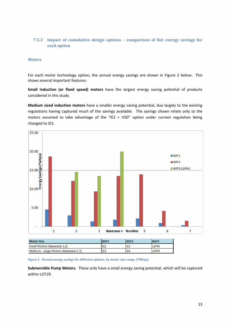
7.5.3 Impact of cumulative design options – comparison of Net energy savings for
each option
Motors
For each motor technology option, the annual energy savings are shown in Figure 2 below. This shows several important features:
Small induction (or fixed speed) motors have the largest energy saving potential of products
considered in this study.
Medium sized induction motors have a smaller energy saving potential, due largely to the existing
regulations having captured much of the savings available. The savings shown relate only to the
motors assumed to take advantage of the “IE2 + VSD” option under current regulation being
changed to IE3.
Figure 2 Annual energy savings for different options, by motor size range, (TWhpa)
Submersible Pump Motors. These only have a small energy saving potential, which will be captured
within LOT29.
14
Variable Speed Drive
Based on the data received, the energy saving potential for VSDs is very small, and cost prohibitive.
However, the use of motors that can only work when connected to a VSD means that the use of a
VSD makes possible BAT4 and 5 motor technologies, as below.
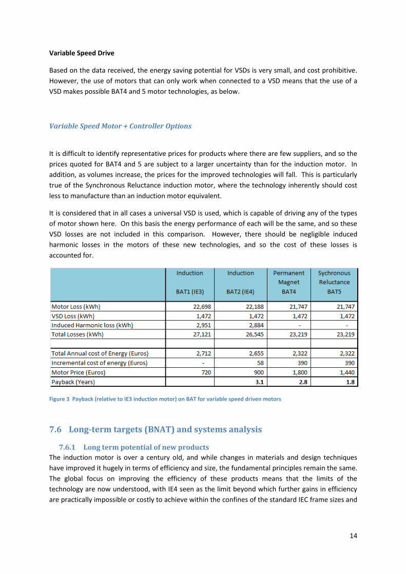
Variable Speed Motor + Controller Options
It is difficult to identify representative prices for products where there are few suppliers, and so the
prices quoted for BAT4 and 5 are subject to a larger uncertainty than for the induction motor. In
addition, as volumes increase, the prices for the improved technologies will fall. This is particularly
true of the Synchronous Reluctance induction motor, where the technology inherently should cost
less to manufacture than an induction motor equivalent.
It is considered that in all cases a universal VSD is used, which is capable of driving any of the types
of motor shown here. On this basis the energy performance of each will be the same, and so these
VSD losses are not included in this comparison. However, there should be negligible induced
harmonic losses in the motors of these new technologies, and so the cost of these losses is
accounted for.
Figure 3 Payback (relative to IE3 induction motor) on BAT for variable speed driven motors
7.6 Long-term targets (BNAT) and systems analysis
7.6.1 Long term potential of new products
The induction motor is over a century old, and while changes in materials and design techniques
have improved it hugely in terms of efficiency and size, the fundamental principles remain the same.
The global focus on improving the efficiency of these products means that the limits of the
technology are now understood, with IE4 seen as the limit beyond which further gains in efficiency
are practically impossible or costly to achieve within the confines of the standard IEC frame sizes and
15
50Hz frequency that are the standard across Europe. Some manufacturers already have IE4 motors
available at commercial or prototype level in some sizes.
The only major new design option is the use of copper for the rotor, which is a practical option
already used by some manufacturers as a way to achieve higher efficiencies within the same volume.
Indicatively this method can achieve at least a further half IE grade1 for the same dimensions.
Disadvantages are a higher cost in some sizes, and higher rotor inertia due to the additional rotor
mass.
Beyond this, Line Start Permanent Magnet motors offer currently offer the only practical
opportunity to achieve higher efficiency. However, this is limited in the maximum size in which it is
available.
A VSD driven induction motor depresses the efficiency of the motor by an estimated 10-16%,
equivalent to about half one IE grade. Further improvements to the high frequency performance of
the motor are expected to help reduce this loss, which should be seen in the context of the large
(often >50%) energy savings in the system that it is controlling.
The energy losses within the VSD itself are small, and should again be seen in the context of the
bigger system savings that they enable.
New types of power semiconductor offer lower losses, both through lower switching losses and
lower on state losses. These might reduce losses by about 25%. This will impact all types of motor
controller by a similar amount, and is the likely basis of the BAT show.
New types of motors that require controllers are slowly being commercialized, which offer superior
energy performance to variable speed induction motors. The offering of motors sold with dedicated
controllers is changing the market towards considering the whole drive package as a “black box”.
This makes it easier for new technologies to gain market share, but until they reach a critical market
share they will always be at a disadvantage compared to the ready availability and inter-
changeability of the induction motor. In the context of this study they represent very best BAT or
BNAT, and so developments in this market should be closely followed to ensure that any policy
options selected encourage their uptake. Currently the two options are: Permanent Magnet and
Synchronous Reluctance.
7.6.2 Long term changes in application of motors
The application of Motor is so broad that no single change in end use will have much impact on the
overall market. However, in countries with a declining industrial base there is a shift from industrial
to commercial applications, with HVAC applications becoming more important. This phenomenon is
behind the growth in the application of VSDs, which are well suited to the varying flows found in
HVAC systems. This is also reflected in an increase in the relative share of smaller motors compared
to larger motors.
1 Reference, International Copper Association
16
7.7 Conclusions
This section has identified the technical improvement options for each of the basecase considered.
Provisional estimates of the energy saving potential of each have been made, with Least Life Cycle
Cost analysis to identify those products that represent the best purchasing option to the consumer.
The analysis has identified the following technically and economically preferred options for each of
the following technologies:
Single Phase and Small Three phase Induction motors: It is economic to increase the efficiency of
these motors to IE2.
Large motors (>375kW to 1000kW): It is economic to increase the efficiency of these motors to IE3.
Excluded motors: Explosion proof and brake motors should be bought into scope, closing a current
loophole.
The cost performance of IE4 motors looks attractive for some medium and large motors, but these
products to dat3 have only limited availability.
VSDs: It is not economic to define a MEPS for VSDs, but it seems relevant to remove from the
market low efficiency units (below IE1 as defined by EN 50598-2)..
Improved variable speed motor technology, in particular Permanent Magnet and Synchronous
Reluctance motors, can offer good energy savings. However, it is unreasonable to set MEPS
regulations at a level that effectively demands these, as they are only available from a small number
of suppliers, and there are technical reasons why they cannot be used in every application.
It should be noted that the wider system energy savings from the use of variable speed controlled
motors is not considered, which would represent considerable further energy savings. This point
should be kept foremost when considering regulatory options.