etsi ts 136 331 v9.12 · 3gpp ts 36.331 version 9.1 etsi 2.0 release 9 5 etsi ts 136 331 v9.12.0...
TRANSCRIPT

ETSI TS 136 331 V9.12.0 (2012-11)
LTE; Evolved Universal Terrestrial Radio Access (E-UTRA);
Radio Resource Control (RRC); Protocol specification
(3GPP TS 36.331 version 9.12.0 Release 9)
Technical Specification
ETSI
ETSI TS 136 331 V9.12.0 (2012-11)13GPP TS 36.331 version 9.12.0 Release 9
Reference RTS/TSGR-0236331v9c0
Keywords LTE
ETSI
650 Route des Lucioles F-06921 Sophia Antipolis Cedex - FRANCE
Tel.: +33 4 92 94 42 00 Fax: +33 4 93 65 47 16
Siret N° 348 623 562 00017 - NAF 742 C
Association à but non lucratif enregistrée à la Sous-Préfecture de Grasse (06) N° 7803/88
Important notice
Individual copies of the present document can be downloaded from: http://www.etsi.org
The present document may be made available in more than one electronic version or in print. In any case of existing or perceived difference in contents between such versions, the reference version is the Portable Document Format (PDF).
In case of dispute, the reference shall be the printing on ETSI printers of the PDF version kept on a specific network drive within ETSI Secretariat.
Users of the present document should be aware that the document may be subject to revision or change of status. Information on the current status of this and other ETSI documents is available at
http://portal.etsi.org/tb/status/status.asp
If you find errors in the present document, please send your comment to one of the following services: http://portal.etsi.org/chaircor/ETSI_support.asp
Copyright Notification
No part may be reproduced except as authorized by written permission. The copyright and the foregoing restriction extend to reproduction in all media.
© European Telecommunications Standards Institute 2012.
All rights reserved.
DECTTM, PLUGTESTSTM, UMTSTM and the ETSI logo are Trade Marks of ETSI registered for the benefit of its Members. 3GPPTM and LTE™ are Trade Marks of ETSI registered for the benefit of its Members and
of the 3GPP Organizational Partners. GSM® and the GSM logo are Trade Marks registered and owned by the GSM Association.
ETSI
ETSI TS 136 331 V9.12.0 (2012-11)23GPP TS 36.331 version 9.12.0 Release 9
Intellectual Property Rights IPRs essential or potentially essential to the present document may have been declared to ETSI. The information pertaining to these essential IPRs, if any, is publicly available for ETSI members and non-members, and can be found in ETSI SR 000 314: "Intellectual Property Rights (IPRs); Essential, or potentially Essential, IPRs notified to ETSI in respect of ETSI standards", which is available from the ETSI Secretariat. Latest updates are available on the ETSI Web server (http://ipr.etsi.org).
Pursuant to the ETSI IPR Policy, no investigation, including IPR searches, has been carried out by ETSI. No guarantee can be given as to the existence of other IPRs not referenced in ETSI SR 000 314 (or the updates on the ETSI Web server) which are, or may be, or may become, essential to the present document.
Foreword This Technical Specification (TS) has been produced by ETSI 3rd Generation Partnership Project (3GPP).
The present document may refer to technical specifications or reports using their 3GPP identities, UMTS identities or GSM identities. These should be interpreted as being references to the corresponding ETSI deliverables.
The cross reference between GSM, UMTS, 3GPP and ETSI identities can be found under http://webapp.etsi.org/key/queryform.asp.

ETSI
ETSI TS 136 331 V9.12.0 (2012-11)33GPP TS 36.331 version 9.12.0 Release 9
Contents
Intellectual Property Rights ................................................................................................................................ 2
Foreword ............................................................................................................................................................. 2
Foreword ........................................................................................................................................................... 12
1 Scope ...................................................................................................................................................... 13
2 References .............................................................................................................................................. 13
3 Definitions, symbols and abbreviations ................................................................................................. 15
3.1 Definitions ........................................................................................................................................................ 15
3.2 Abbreviations ................................................................................................................................................... 16
4 General ................................................................................................................................................... 17
4.1 Introduction ...................................................................................................................................................... 17
4.2 Architecture ...................................................................................................................................................... 18
4.2.1 UE states and state transitions including inter RAT ................................................................................... 18
4.2.2 Signalling radio bearers .............................................................................................................................. 19
4.3 Services ............................................................................................................................................................ 20
4.3.1 Services provided to upper layers ............................................................................................................... 20
4.3.2 Services expected from lower layers .......................................................................................................... 20
4.4 Functions .......................................................................................................................................................... 20
5 Procedures .............................................................................................................................................. 21
5.1 General ............................................................................................................................................................. 21
5.1.1 Introduction................................................................................................................................................. 21
5.1.2 General requirements .................................................................................................................................. 21
5.2 System information .......................................................................................................................................... 22
5.2.1 Introduction................................................................................................................................................. 22
5.2.1.1 General .................................................................................................................................................. 22
5.2.1.2 Scheduling ............................................................................................................................................. 22
5.2.1.3 System information validity and notification of changes ...................................................................... 23
5.2.1.4 Indication of ETWS notification ........................................................................................................... 24
5.2.1.5 Indication of CMAS notification ........................................................................................................... 24
5.2.2 System information acquisition .................................................................................................................. 24
5.2.2.1 General .................................................................................................................................................. 24
5.2.2.2 Initiation ................................................................................................................................................ 25
5.2.2.3 System information required by the UE ................................................................................................ 25
5.2.2.4 System information acquisition by the UE ............................................................................................ 25
5.2.2.5 Essential system information missing ................................................................................................... 26
5.2.2.6 Actions upon reception of the MasterInformationBlock message ......................................................... 27
5.2.2.7 Actions upon reception of the SystemInformationBlockType1 message ............................................... 27
5.2.2.8 Actions upon reception of SystemInformation messages ...................................................................... 27
5.2.2.9 Actions upon reception of SystemInformationBlockType2 ................................................................... 27
5.2.2.10 Actions upon reception of SystemInformationBlockType3 ................................................................... 28
5.2.2.11 Actions upon reception of SystemInformationBlockType4 ................................................................... 28
5.2.2.12 Actions upon reception of SystemInformationBlockType5 ................................................................... 28
5.2.2.13 Actions upon reception of SystemInformationBlockType6 ................................................................... 28
5.2.2.14 Actions upon reception of SystemInformationBlockType7 ................................................................... 28
5.2.2.15 Actions upon reception of SystemInformationBlockType8 ................................................................... 28
5.2.2.16 Actions upon reception of SystemInformationBlockType9 ................................................................... 29
5.2.2.17 Actions upon reception of SystemInformationBlockType10 ................................................................. 29
5.2.2.18 Actions upon reception of SystemInformationBlockType11 ................................................................. 29
5.2.2.19 Actions upon reception of SystemInformationBlockType12 ................................................................. 30
5.2.2.20 Actions upon reception of SystemInformationBlockType13 ................................................................. 31
5.2.3 Acquisition of an SI message ...................................................................................................................... 31
5.3 Connection control ........................................................................................................................................... 31
5.3.1 Introduction................................................................................................................................................. 31
5.3.1.1 RRC connection control ........................................................................................................................ 31

ETSI
ETSI TS 136 331 V9.12.0 (2012-11)43GPP TS 36.331 version 9.12.0 Release 9
5.3.1.2 Security ................................................................................................................................................. 32
5.3.1.3 Connected mode mobility ..................................................................................................................... 32
5.3.2 Paging ......................................................................................................................................................... 33
5.3.2.1 General .................................................................................................................................................. 33
5.3.2.2 Initiation ................................................................................................................................................ 34
5.3.2.3 Reception of the Paging message by the UE ........................................................................................ 34
5.3.3 RRC connection establishment ................................................................................................................... 35
5.3.3.1 General .................................................................................................................................................. 35
5.3.3.2 Initiation ................................................................................................................................................ 35
5.3.3.3 Actions related to transmission of RRCConnectionRequest message ................................................... 38
5.3.3.4 Reception of the RRCConnectionSetup by the UE ................................................................................ 38
5.3.3.5 Cell re-selection while T300, T302, T303 or T305 is running .............................................................. 39
5.3.3.6 T300 expiry ........................................................................................................................................... 39
5.3.3.7 T302, T303 or T305 expiry or stop ....................................................................................................... 39
5.3.3.8 Reception of the RRCConnectionReject by the UE .............................................................................. 40
5.3.3.9 Abortion of RRC connection establishment .......................................................................................... 40
5.3.3.10 Handling of SSAC related parameters ........................................................................................................ 40
5.3.4 Initial security activation ............................................................................................................................ 41
5.3.4.1 General .................................................................................................................................................. 41
5.3.4.2 Initiation ................................................................................................................................................ 41
5.3.4.3 Reception of the SecurityModeCommand by the UE ............................................................................ 41
5.3.5 RRC connection reconfiguration ................................................................................................................ 42
5.3.5.1 General .................................................................................................................................................. 42
5.3.5.2 Initiation ................................................................................................................................................ 43
5.3.5.3 Reception of an RRCConnectionReconfiguration not including the mobilityControlInfo by the UE ......................................................................................................................................................... 43
5.3.5.4 Reception of an RRCConnectionReconfiguration including the mobilityControlInfo by the UE (handover) ............................................................................................................................................. 44
5.3.5.5 Reconfiguration failure ......................................................................................................................... 45
5.3.5.6 T304 expiry (handover failure) ............................................................................................................. 46
5.3.5.7 Void....................................................................................................................................................... 46
5.3.5.8 Radio Configuration involving full configuration option...................................................................... 46
5.3.6 Counter check ............................................................................................................................................. 47
5.3.6.1 General .................................................................................................................................................. 47
5.3.6.2 Initiation ................................................................................................................................................ 47
5.3.6.3 Reception of the CounterCheck message by the UE ............................................................................. 47
5.3.7 RRC connection re-establishment ............................................................................................................... 48
5.3.7.1 General .................................................................................................................................................. 48
5.3.7.2 Initiation ................................................................................................................................................ 49
5.3.7.3 Actions following cell selection while T311 is running ........................................................................ 49
5.3.7.4 Actions related to transmission of RRCConnectionReestablishmentRequest message ......................... 49
5.3.7.5 Reception of the RRCConnectionReestablishment by the UE .............................................................. 50
5.3.7.6 T311 expiry ........................................................................................................................................... 51
5.3.7.7 T301 expiry or selected cell no longer suitable ..................................................................................... 51
5.3.7.8 Reception of RRCConnectionReestablishmentReject by the UE .......................................................... 51
5.3.8 RRC connection release .............................................................................................................................. 51
5.3.8.1 General .................................................................................................................................................. 51
5.3.8.2 Initiation ................................................................................................................................................ 52
5.3.8.3 Reception of the RRCConnectionRelease by the UE ............................................................................ 52
5.3.8.4 T320 expiry ........................................................................................................................................... 52
5.3.9 RRC connection release requested by upper layers .................................................................................... 52
5.3.9.1 General .................................................................................................................................................. 52
5.3.9.2 Initiation ................................................................................................................................................ 52
5.3.10 Radio resource configuration ...................................................................................................................... 53
5.3.10.0 General .................................................................................................................................................. 53
5.3.10.1 SRB addition/ modification ................................................................................................................... 53
5.3.10.2 DRB release .......................................................................................................................................... 53
5.3.10.3 DRB addition/ modification .................................................................................................................. 54
5.3.10.4 MAC main reconfiguration ................................................................................................................... 54
5.3.10.5 Semi-persistent scheduling reconfiguration .......................................................................................... 55
5.3.10.6 Physical channel reconfiguration .......................................................................................................... 55
5.3.10.7 Radio Link Failure Timers and Constants reconfiguration ................................................................... 55

ETSI
ETSI TS 136 331 V9.12.0 (2012-11)53GPP TS 36.331 version 9.12.0 Release 9
5.3.11 Radio link failure related actions ................................................................................................................ 55
5.3.11.1 Detection of physical layer problems in RRC_CONNECTED ............................................................. 55
5.3.11.2 Recovery of physical layer problems .................................................................................................... 55
5.3.11.3 Detection of radio link failure ............................................................................................................... 56
5.3.12 UE actions upon leaving RRC_CONNECTED .......................................................................................... 56
5.3.13 UE actions upon PUCCH/ SRS release request .......................................................................................... 56
5.3.14 Proximity indication ................................................................................................................................... 57
5.3.14.1 General .................................................................................................................................................. 57
5.3.14.2 Initiation ................................................................................................................................................ 57
5.3.14.3 Actions related to transmission of ProximityIndication message.......................................................... 57
5.4 Inter-RAT mobility........................................................................................................................................... 58
5.4.1 Introduction................................................................................................................................................. 58
5.4.2 Handover to E-UTRA ................................................................................................................................. 58
5.4.2.1 General .................................................................................................................................................. 58
5.4.2.2 Initiation ................................................................................................................................................ 58
5.4.2.3 Reception of the RRCConnectionReconfiguration by the UE ............................................................... 58
5.4.2.4 Reconfiguration failure ......................................................................................................................... 60
5.4.2.5 T304 expiry (handover to E-UTRA failure) .......................................................................................... 60
5.4.3 Mobility from E-UTRA .............................................................................................................................. 60
5.4.3.1 General .................................................................................................................................................. 60
5.4.3.2 Initiation ................................................................................................................................................ 61
5.4.3.3 Reception of the MobilityFromEUTRACommand by the UE ............................................................... 61
5.4.3.4 Successful completion of the mobility from E-UTRA .......................................................................... 62
5.4.3.5 Mobility from E-UTRA failure ............................................................................................................. 62
5.4.4 Handover from E-UTRA preparation request (CDMA2000) ..................................................................... 63
5.4.4.1 General .................................................................................................................................................. 63
5.4.4.2 Initiation ................................................................................................................................................ 63
5.4.4.3 Reception of the HandoverFromEUTRAPreparationRequest by the UE ............................................. 63
5.4.5 UL handover preparation transfer (CDMA2000) ....................................................................................... 64
5.4.5.1 General .................................................................................................................................................. 64
5.4.5.2 Initiation ................................................................................................................................................ 64
5.4.5.3 Actions related to transmission of the ULHandoverPreparationTransfer message .............................. 64
5.4.5.4 Failure to deliver the ULHandoverPreparationTransfer message ........................................................ 64
5.4.6 Inter-RAT cell change order to E-UTRAN ................................................................................................. 64
5.4.6.1 General .................................................................................................................................................. 64
5.4.6.2 Initiation ................................................................................................................................................ 65
5.4.6.3 UE fails to complete an inter-RAT cell change order ........................................................................... 65
5.5 Measurements ................................................................................................................................................... 65
5.5.1 Introduction................................................................................................................................................. 65
5.5.2 Measurement configuration ........................................................................................................................ 67
5.5.2.1 General .................................................................................................................................................. 67
5.5.2.2 Measurement identity removal .............................................................................................................. 67
5.5.2.3 Measurement identity addition/ modification ....................................................................................... 68
5.5.2.4 Measurement object removal ................................................................................................................ 69
5.5.2.5 Measurement object addition/ modification .......................................................................................... 69
5.5.2.6 Reporting configuration removal .......................................................................................................... 70
5.5.2.7 Reporting configuration addition/ modification .................................................................................... 70
5.5.2.8 Quantity configuration .......................................................................................................................... 70
5.5.2.9 Measurement gap configuration ............................................................................................................ 71
5.5.3 Performing measurements .......................................................................................................................... 71
5.5.3.1 General .................................................................................................................................................. 71
5.5.3.2 Layer 3 filtering .................................................................................................................................... 72
5.5.4 Measurement report triggering ................................................................................................................... 73
5.5.4.1 General .................................................................................................................................................. 73
5.5.4.2 Event A1 (Serving becomes better than threshold) ............................................................................... 75
5.5.4.3 Event A2 (Serving becomes worse than threshold) .............................................................................. 76
5.5.4.4 Event A3 (Neighbour becomes offset better than serving) ................................................................... 76
5.5.4.5 Event A4 (Neighbour becomes better than threshold) .......................................................................... 77
5.5.4.6 Event A5 (Serving becomes worse than threshold1 and neighbour becomes better than threshold2) ............................................................................................................................................ 77
5.5.4.7 Event B1 (Inter RAT neighbour becomes better than threshold) .......................................................... 78

ETSI
ETSI TS 136 331 V9.12.0 (2012-11)63GPP TS 36.331 version 9.12.0 Release 9
5.5.4.8 Event B2 (Serving becomes worse than threshold1 and inter RAT neighbour becomes better than threshold2) ............................................................................................................................................ 79
5.5.5 Measurement reporting ............................................................................................................................... 80
5.5.6 Measurement related actions....................................................................................................................... 81
5.5.6.1 Actions upon handover and re-establishment........................................................................................ 81
5.5.6.2 Speed dependant scaling of measurement related parameters ............................................................... 82
5.6 Other ................................................................................................................................................................. 83
5.6.1 DL information transfer .............................................................................................................................. 83
5.6.1.1 General .................................................................................................................................................. 83
5.6.1.2 Initiation ................................................................................................................................................ 83
5.6.1.3 Reception of the DLInformationTransfer by the UE ............................................................................ 83
5.6.2 UL information transfer .............................................................................................................................. 83
5.6.2.1 General .................................................................................................................................................. 83
5.6.2.2 Initiation ................................................................................................................................................ 83
5.6.2.3 Actions related to transmission of ULInformationTransfer message .................................................... 84
5.6.2.4 Failure to deliver ULInformationTransfer message .............................................................................. 84
5.6.3 UE capability transfer ................................................................................................................................. 84
5.6.3.1 General .................................................................................................................................................. 84
5.6.3.2 Initiation ................................................................................................................................................ 85
5.6.3.3 Reception of the UECapabilityEnquiry by the UE ............................................................................... 85
5.6.4 CSFB to 1x Parameter transfer ................................................................................................................... 86
5.6.4.1 General .................................................................................................................................................. 86
5.6.4.2 Initiation ................................................................................................................................................ 86
5.6.4.3 Actions related to transmission of CSFBParametersRequestCDMA2000 message .............................. 86
5.6.4.4 Reception of the CSFBParametersResponseCDMA2000 message ....................................................... 86
5.6.5 UE Information ........................................................................................................................................... 87
5.6.5.1 General .................................................................................................................................................. 87
5.6.5.2 Initiation ................................................................................................................................................ 87
5.6.5.3 Reception of the UEInformationRequest message ................................................................................ 87
5.7 Generic error handling ...................................................................................................................................... 88
5.7.1 General ........................................................................................................................................................ 88
5.7.2 ASN.1 violation or encoding error .............................................................................................................. 88
5.7.3 Field set to a not comprehended value ........................................................................................................ 88
5.7.4 Mandatory field missing ............................................................................................................................. 88
5.7.5 Not comprehended field .............................................................................................................................. 89
5.8 MBMS .............................................................................................................................................................. 89
5.8.1 Introduction................................................................................................................................................. 89
5.8.1.1 General .................................................................................................................................................. 89
5.8.1.2 Scheduling ............................................................................................................................................. 90
5.8.1.3 MCCH information validity and notification of changes ...................................................................... 90
5.8.2 MCCH information acquisition .................................................................................................................. 91
5.8.2.1 General .................................................................................................................................................. 91
5.8.2.2 Initiation ................................................................................................................................................ 91
5.8.2.3 MCCH information acquisition by the UE ............................................................................................ 91
5.8.2.4 Actions upon reception of the MBSFNAreaConfiguration message ..................................................... 91
5.8.3 MBMS PTM radio bearer configuration ..................................................................................................... 92
5.8.3.1 General .................................................................................................................................................. 92
5.8.3.2 Initiation ................................................................................................................................................ 92
5.8.3.3 MRB establishment ............................................................................................................................... 92
5.8.3.4 MRB release .......................................................................................................................................... 92
6 Protocol data units, formats and parameters (tabular & ASN.1) ............................................................ 92
6.1 General ............................................................................................................................................................. 92
6.2 RRC messages .................................................................................................................................................. 93
6.2.1 General message structure .......................................................................................................................... 93
– EUTRA-RRC-Definitions ...................................................................................................................... 93
– BCCH-BCH-Message ........................................................................................................................... 93
– BCCH-DL-SCH-Message ..................................................................................................................... 94
– MCCH-Message .................................................................................................................................... 94
– PCCH-Message ..................................................................................................................................... 94
– DL-CCCH-Message .............................................................................................................................. 95
– DL-DCCH-Message .............................................................................................................................. 95

ETSI
ETSI TS 136 331 V9.12.0 (2012-11)73GPP TS 36.331 version 9.12.0 Release 9
– UL-CCCH-Message .............................................................................................................................. 95
– UL-DCCH-Message .............................................................................................................................. 96
6.2.2 Message definitions .................................................................................................................................... 96
– CounterCheck ........................................................................................................................................ 96
– CounterCheckResponse ......................................................................................................................... 97
– CSFBParametersRequestCDMA2000 ................................................................................................... 98
– CSFBParametersResponseCDMA2000 ................................................................................................ 98
– DLInformationTransfer ......................................................................................................................... 99
– HandoverFromEUTRAPreparationRequest (CDMA2000) .................................................................. 99
– MasterInformationBlock ..................................................................................................................... 100
– MBSFNAreaConfiguration ................................................................................................................. 101
– MeasurementReport ............................................................................................................................ 102
– MobilityFromEUTRACommand .......................................................................................................... 102
– Paging ................................................................................................................................................. 105
– ProximityIndication............................................................................................................................. 106
– RRCConnectionReconfiguration ......................................................................................................... 107
– RRCConnectionReconfigurationComplete .......................................................................................... 108
– RRCConnectionReestablishment ......................................................................................................... 109
– RRCConnectionReestablishmentComplete ......................................................................................... 109
– RRCConnectionReestablishmentReject ............................................................................................... 110
– RRCConnectionReestablishmentRequest ............................................................................................ 111
– RRCConnectionReject ......................................................................................................................... 111
– RRCConnectionRelease ...................................................................................................................... 112
– RRCConnectionRequest ...................................................................................................................... 114
– RRCConnectionSetup .......................................................................................................................... 115
– RRCConnectionSetupComplete ........................................................................................................... 116
– SecurityModeCommand ...................................................................................................................... 117
– SecurityModeComplete ....................................................................................................................... 117
– SecurityModeFailure........................................................................................................................... 118
– SystemInformation .............................................................................................................................. 119
– SystemInformationBlockType1 ............................................................................................................ 119
– UECapabilityEnquiry .......................................................................................................................... 121
– UECapabilityInformation ................................................................................................................... 122
– UEInformationRequest ........................................................................................................................ 123
– UEInformationResponse ..................................................................................................................... 123
– ULHandoverPreparationTransfer (CDMA2000) ................................................................................ 125
– ULInformationTransfer ....................................................................................................................... 125
6.3 RRC information elements ............................................................................................................................. 126
6.3.1 System information blocks ....................................................................................................................... 126
– SystemInformationBlockType2 ............................................................................................................ 126
– SystemInformationBlockType3 ............................................................................................................ 127
– SystemInformationBlockType4 ............................................................................................................ 129
– SystemInformationBlockType5 ............................................................................................................ 130
– SystemInformationBlockType6 ............................................................................................................ 132
– SystemInformationBlockType7 ............................................................................................................ 133
– SystemInformationBlockType8 ............................................................................................................ 134
– SystemInformationBlockType9 ............................................................................................................ 137
– SystemInformationBlockType10 .......................................................................................................... 137
– SystemInformationBlockType11 .......................................................................................................... 138
– SystemInformationBlockType12 .......................................................................................................... 139
– SystemInformationBlockType13 .......................................................................................................... 140
6.3.2 Radio resource control information elements ........................................................................................... 140
– AntennaInfo ......................................................................................................................................... 140
– CQI-ReportConfig ............................................................................................................................... 141
– DRB-Identity ....................................................................................................................................... 142
– LogicalChannelConfig ........................................................................................................................ 142
– MAC-MainConfig ................................................................................................................................ 143
– PDCP-Config ...................................................................................................................................... 145
– PDSCH-Config .................................................................................................................................... 146
– PHICH-Config .................................................................................................................................... 147
– PhysicalConfigDedicated .................................................................................................................... 147
– P-Max .................................................................................................................................................. 148

ETSI
ETSI TS 136 331 V9.12.0 (2012-11)83GPP TS 36.331 version 9.12.0 Release 9
– PRACH-Config .................................................................................................................................... 148
– PresenceAntennaPort1 ........................................................................................................................ 149
– PUCCH-Config ................................................................................................................................... 149
– PUSCH-Config .................................................................................................................................... 150
– RACH-ConfigCommon ........................................................................................................................ 151
– RACH-ConfigDedicated ...................................................................................................................... 152
– RadioResourceConfigCommon ........................................................................................................... 153
– RadioResourceConfigDedicated ......................................................................................................... 154
– RLC-Config ......................................................................................................................................... 155
– RLF-TimersAndConstants ................................................................................................................... 157
– SchedulingRequestConfig ................................................................................................................... 157
– SoundingRS-UL-Config ....................................................................................................................... 158
– SPS-Config .......................................................................................................................................... 159
– TDD-Config ........................................................................................................................................ 160
– TimeAlignmentTimer ........................................................................................................................... 161
– TPC-PDCCH-Config .......................................................................................................................... 161
– UplinkPowerControl ........................................................................................................................... 162
6.3.3 Security control information elements ...................................................................................................... 163
– NextHopChainingCount ...................................................................................................................... 163
– SecurityAlgorithmConfig ..................................................................................................................... 163
– ShortMAC-I ......................................................................................................................................... 164
6.3.4 Mobility control information elements ..................................................................................................... 164
– AdditionalSpectrumEmission .............................................................................................................. 164
– ARFCN-ValueCDMA2000 .................................................................................................................. 164
– ARFCN-ValueEUTRA ......................................................................................................................... 164
– ARFCN-ValueGERAN......................................................................................................................... 165
– ARFCN-ValueUTRA ........................................................................................................................... 165
– BandclassCDMA2000 ......................................................................................................................... 165
– BandIndicatorGERAN......................................................................................................................... 165
– CarrierFreqCDMA2000 ..................................................................................................................... 166
– CarrierFreqGERAN ............................................................................................................................ 166
– CarrierFreqsGERAN .......................................................................................................................... 166
– CDMA2000-Type ................................................................................................................................ 167
– CellIdentity .......................................................................................................................................... 167
– CellIndexList ....................................................................................................................................... 167
– CellReselectionPriority ....................................................................................................................... 168
– CSFB-RegistrationParam1XRTT ........................................................................................................ 168
– CellGlobalIdEUTRA ........................................................................................................................... 169
– CellGlobalIdUTRA .............................................................................................................................. 169
– CellGlobalIdGERAN ........................................................................................................................... 170
– CellGlobalIdCDMA2000 .................................................................................................................... 170
– CSG-Identity........................................................................................................................................ 171
– FreqBandIndicator .............................................................................................................................. 171
– MobilityControlInfo ............................................................................................................................ 171
– MobilityParametersCDMA2000 (1xRTT) ........................................................................................... 172
– MobilityStateParameters ..................................................................................................................... 172
– MultiBandInfoList ............................................................................................................................... 173
– PhysCellId ........................................................................................................................................... 173
– PhysCellIdRange ................................................................................................................................. 173
– PhysCellIdRangeUTRA-FDDList ....................................................................................................... 174
– PhysCellIdCDMA2000 ........................................................................................................................ 174
– PhysCellIdGERAN .............................................................................................................................. 174
– PhysCellIdUTRA-FDD ....................................................................................................................... 175
– PhysCellIdUTRA-TDD ........................................................................................................................ 175
– PLMN-Identity .................................................................................................................................... 175
– PreRegistrationInfoHRPD .................................................................................................................. 176
– Q-QualMin .......................................................................................................................................... 176
– Q-RxLevMin ........................................................................................................................................ 176
– Q-OffsetRange ..................................................................................................................................... 177
– Q-OffsetRangeInterRAT ...................................................................................................................... 177
– ReselectionThreshold .......................................................................................................................... 177
– ReselectionThresholdQ ....................................................................................................................... 177

ETSI
ETSI TS 136 331 V9.12.0 (2012-11)93GPP TS 36.331 version 9.12.0 Release 9
– SpeedStateScaleFactors ...................................................................................................................... 177
– SystemInfoListGERAN ........................................................................................................................ 178
– SystemTimeInfoCDMA2000 ................................................................................................................ 178
– TrackingAreaCode .............................................................................................................................. 179
– T-Reselection ....................................................................................................................................... 179
6.3.5 Measurement information elements .......................................................................................................... 179
– AllowedMeasBandwidth ...................................................................................................................... 179
– Hysteresis ............................................................................................................................................ 179
– MeasConfig ......................................................................................................................................... 180
– MeasGapConfig .................................................................................................................................. 181
– MeasId ................................................................................................................................................. 181
– MeasIdToAddModList ......................................................................................................................... 181
– MeasObjectCDMA2000 ...................................................................................................................... 181
– MeasObjectEUTRA ............................................................................................................................. 182
– MeasObjectGERAN............................................................................................................................. 183
– MeasObjectId ...................................................................................................................................... 183
– MeasObjectToAddModList ................................................................................................................. 184
– MeasObjectUTRA ............................................................................................................................... 184
– MeasResults ........................................................................................................................................ 185
– QuantityConfig .................................................................................................................................... 188
– ReportConfigEUTRA........................................................................................................................... 188
– ReportConfigId .................................................................................................................................... 190
– ReportConfigInterRAT ........................................................................................................................ 190
– ReportConfigToAddModList ............................................................................................................... 192
– ReportInterval ..................................................................................................................................... 192
– RSRP-Range ........................................................................................................................................ 193
– RSRQ-Range ....................................................................................................................................... 193
– TimeToTrigger .................................................................................................................................... 193
6.3.6 Other information elements ...................................................................................................................... 193
– C-RNTI ................................................................................................................................................ 193
– DedicatedInfoCDMA2000 ................................................................................................................... 194
– DedicatedInfoNAS ............................................................................................................................... 194
– FilterCoefficient .................................................................................................................................. 194
– MMEC ................................................................................................................................................. 194
– NeighCellConfig .................................................................................................................................. 194
– OtherConfig ........................................................................................................................................ 195
– RAND-CDMA2000 (1xRTT) ............................................................................................................... 195
– RAT-Type ............................................................................................................................................ 195
– RRC-TransactionIdentifier .................................................................................................................. 196
– S-TMSI ................................................................................................................................................ 196
– UE-CapabilityRAT-ContainerList ....................................................................................................... 196
– UE-EUTRA-Capability ....................................................................................................................... 197
– UE-TimersAndConstants ..................................................................................................................... 202
6.3.7 MBMS information elements ................................................................................................................... 203
– MBMS-NotificationConfig .................................................................................................................. 203
– MBSFN-AreaInfoList .......................................................................................................................... 203
– MBSFN-SubframeConfig .................................................................................................................... 204
– PMCH-InfoList .................................................................................................................................... 205
6.4 RRC multiplicity and type constraint values .................................................................................................. 206
– Multiplicity and type constraint definitions .............................................................................................. 206
– End of EUTRA-RRC-Definitions ............................................................................................................. 207
7 Variables and constants ........................................................................................................................ 207
7.1 UE variables ................................................................................................................................................... 207
– EUTRA-UE-Variables ......................................................................................................................... 207
– VarMeasConfig ................................................................................................................................... 208
– VarMeasReportList ............................................................................................................................. 208
– VarShortMAC-Input ............................................................................................................................ 208
– Multiplicity and type constraint definitions ........................................................................................ 209
– End of EUTRA-UE-Variables ............................................................................................................. 209
7.2 Counters ......................................................................................................................................................... 209
7.3 Timers (Informative) ...................................................................................................................................... 210

ETSI
ETSI TS 136 331 V9.12.0 (2012-11)103GPP TS 36.331 version 9.12.0 Release 9
7.4 Constants ........................................................................................................................................................ 211
8 Protocol data unit abstract syntax ......................................................................................................... 211
8.1 General ................................................................................................................................................. 211
8.2 Structure of encoded RRC messages .............................................................................................................. 211
8.3 Basic production ............................................................................................................................................. 212
8.4 Extension ........................................................................................................................................................ 212
8.5 Padding ........................................................................................................................................................... 212
9 Specified and default radio configurations ........................................................................................... 212
9.1 Specified configurations ................................................................................................................................. 213
9.1.1 Logical channel configurations ................................................................................................................. 213
9.1.1.1 BCCH configuration ........................................................................................................................... 213
9.1.1.2 CCCH configuration ........................................................................................................................... 213
9.1.1.3 PCCH configuration ............................................................................................................................ 213
9.1.1.4 MCCH and MTCH configuration ....................................................................................................... 213
9.1.2 SRB configurations ................................................................................................................................... 213
9.1.2.1 SRB1 ................................................................................................................................................... 213
9.1.2.2 SRB2 ................................................................................................................................................... 214
9.2 Default radio configurations ........................................................................................................................... 214
9.2.1 SRB configurations ................................................................................................................................... 214
9.2.1.1 SRB1 ................................................................................................................................................... 214
9.2.1.2 SRB2 ................................................................................................................................................... 214
9.2.2 Default MAC main configuration ............................................................................................................. 215
9.2.3 Default semi-persistent scheduling configuration ..................................................................................... 215
9.2.4 Default physical channel configuration .................................................................................................... 215
9.2.5 Default values timers and constants .......................................................................................................... 216
10 Radio information related interactions between network nodes .......................................................... 216
10.1 General ........................................................................................................................................................... 216
10.2 Inter-node RRC messages .............................................................................................................................. 216
10.2.1 General ...................................................................................................................................................... 216
– EUTRA-InterNodeDefinitions ................................................................................................................... 216
10.2.2 Message definitions .................................................................................................................................. 217
– HandoverCommand ............................................................................................................................ 217
– HandoverPreparationInformation ...................................................................................................... 217
– UERadioAccessCapabilityInformation ............................................................................................... 218
10.3 Inter-node RRC information element definitions ........................................................................................... 219
– AS-Config ............................................................................................................................................ 219
– AS-Context .......................................................................................................................................... 220
– ReestablishmentInfo ............................................................................................................................ 220
– RRM-Config ........................................................................................................................................ 221
10.4 Inter-node RRC multiplicity and type constraint values ................................................................................ 222
– Multiplicity and type constraints definitions ............................................................................................ 222
– End of EUTRA-InterNodeDefinitions ....................................................................................................... 222
10.5 Mandatory information in AS-Config ............................................................................................................. 222
11 UE capability related constraints and performance requirements ........................................................ 224
11.1 UE capability related constraints .................................................................................................................... 224
11.2 Processing delay requirements for RRC procedures ...................................................................................... 225
11.3 Void ................................................................................................................................................................ 227
Annex A (informative): Guidelines, mainly on use of ASN.1 ........................................................... 228
A.1 Introduction .................................................................................................................................................... 228
A.2 Procedural specification ................................................................................................................................. 228
A.2.1 General principles ..................................................................................................................................... 228
A.2.2 More detailed aspects................................................................................................................................ 228
A.3 PDU specification........................................................................................................................................... 228
A.3.1 General principles ..................................................................................................................................... 228
A.3.1.1 ASN.1 sections .................................................................................................................................... 228
A.3.1.2 ASN.1 identifier naming conventions ................................................................................................. 229
A.3.1.3 Text references using ASN.1 identifiers ............................................................................................. 230
A.3.2 High-level message structure .................................................................................................................... 231

ETSI
ETSI TS 136 331 V9.12.0 (2012-11)113GPP TS 36.331 version 9.12.0 Release 9
A.3.3 Message definition .................................................................................................................................... 231
A.3.4 Information elements ................................................................................................................................ 233
A.3.5 Fields with optional presence.................................................................................................................... 234
A.3.6 Fields with conditional presence ............................................................................................................... 234
A.3.7 Guidelines on use of lists with elements of SEQUENCE type ................................................................. 235
A.4 Extension of the PDU specifications .............................................................................................................. 235
A.4.1 General principles to ensure compatibility ............................................................................................... 235
A.4.2 Critical extension of messages .................................................................................................................. 236
A.4.3 Non-critical extension of messages .......................................................................................................... 237
A.4.3.1 General principles ............................................................................................................................... 237
A.4.3.2 Further guidelines ............................................................................................................................... 237
A.4.3.3 Typical example of evolution of IE with local extensions .................................................................. 238
A.4.3.4 Typical examples of non critical extension at the end of a message ................................................... 239
A.4.3.5 Examples of non-critical extensions not placed at the default extension location .............................. 239
– ParentIE-WithEM ............................................................................................................................... 240
– ChildIE1-WithoutEM .......................................................................................................................... 240
– ChildIE2-WithoutEM .......................................................................................................................... 241
A.5 Guidelines regarding inclusion of transaction identifiers in RRC messages .................................................. 241
A.6 Protection of RRC messages (informative) .................................................................................................... 242
A.7 Miscellaneous ................................................................................................................................................. 244
Annex B (normative): Release 8 and 9 AS feature handling .................................................................... 245
B.1 Feature group indicators ................................................................................................................................. 245
B.2 CSG support ................................................................................................................................................... 253
Annex C (informative): Change history ..................................................................................................... 254
History ............................................................................................................................................................ 260

ETSI
ETSI TS 136 331 V9.12.0 (2012-11)123GPP TS 36.331 version 9.12.0 Release 9
Foreword This Technical Specification has been produced by the 3rd Generation Partnership Project (3GPP).
The contents of the present document are subject to continuing work within the TSG and may change following formal TSG approval. Should the TSG modify the contents of the present document, it will be re-released by the TSG with an identifying change of release date and an increase in version number as follows:
Version x.y.z
where:
x the first digit:
1 presented to TSG for information;
2 presented to TSG for approval;
3 or greater indicates TSG approved document under change control.
y the second digit is incremented for all changes of substance, i.e. technical enhancements, corrections, updates, etc.
z the third digit is incremented when editorial only changes have been incorporated in the document.

ETSI
ETSI TS 136 331 V9.12.0 (2012-11)133GPP TS 36.331 version 9.12.0 Release 9
1 Scope The present document specifies the Radio Resource Control protocol for the UE-E-UTRAN radio interface.
The scope of the present document also includes:
- the radio related information transported in a transparent container between source eNB and target eNB upon inter eNB handover;
- the radio related information transported in a transparent container between a source or target eNB and another system upon inter RAT handover.
2 References The following documents contain provisions which, through reference in this text, constitute provisions of the present document.
• References are either specific (identified by date of publication, edition number, version number, etc.) or non-specific.
• For a specific reference, subsequent revisions do not apply.
• For a non-specific reference, the latest version applies. In the case of a reference to a 3GPP document (including a GSM document), a non-specific reference implicitly refers to the latest version of that document in the same Release as the present document.
[1] 3GPP TR 21.905: "Vocabulary for 3GPP Specifications".
[2] Void.
[3] 3GPP TS 36.302: "Evolved Universal Terrestrial Radio Access (E-UTRA); Services provided by the physical layer ".
[4] 3GPP TS 36.304: "Evolved Universal Terrestrial Radio Access (E-UTRA); UE Procedures in Idle Mode".
[5] 3GPP TS 36.306 "Evolved Universal Terrestrial Radio Access (E-UTRA); UE Radio Access Capabilities".
[6] 3GPP TS 36.321: "Evolved Universal Terrestrial Radio Access (E-UTRA); Medium Access Control (MAC) protocol specification".
[7] 3GPP TS 36.322:"Evolved Universal Terrestrial Radio Access (E-UTRA); Radio Link Control (RLC) protocol specification".
[8] 3GPP TS 36.323: "Evolved Universal Terrestrial Radio Access (E-UTRA); Packet Data Convergence Protocol (PDCP) Specification".
[9] 3GPP TS 36.300: "Evolved Universal Terrestrial Radio Access (E-UTRA) and Evolved Universal Terrestrial Radio Access (E-UTRAN); Overall description; Stage 2".
[10] 3GPP TS 22.011: "Service accessibility".
[11] 3GPP TS 23.122: "Non-Access-Stratum (NAS) functions related to Mobile Station (MS) in idle mode".
[12] 3GPP2 C.S0002-A v6.0: "Physical Layer Standard for cdma2000 Spread Spectrum Systems – Release A".
[13] ITU-T Recommendation X.680 (07/2002) "Information Technology - Abstract Syntax Notation One (ASN.1): Specification of basic notation" (Same as the ISO/IEC International Standard 8824-1).
ETSI
ETSI TS 136 331 V9.12.0 (2012-11)143GPP TS 36.331 version 9.12.0 Release 9
[14] ITU-T Recommendation X.681 (07/2002) "Information Technology - Abstract Syntax Notation One (ASN.1): Information object specification" (Same as the ISO/IEC International Standard 8824-2).
[15] ITU-T Recommendation X.691 (07/2002) "Information technology - ASN.1 encoding rules: Specification of Packed Encoding Rules (PER)" (Same as the ISO/IEC International Standard 8825-2).
[16] 3GPP TS 36.133: "Evolved Universal Terrestrial Radio Access (E-UTRA); Requirements for support of radio resource management".
[17] 3GPP TS 25.101: "Universal Terrestrial Radio Access (UTRA); User Equipment (UE) radio transmission and reception (FDD)".
[18] 3GPP TS 25.102: "Universal Terrestrial Radio Access (UTRA); User Equipment (UE) radio transmission and reception (TDD)".
[19] 3GPP TS 25.331:"Universal Terrestrial Radio Access (UTRA); Radio Resource Control (RRC); Protocol specification".
[20] 3GPP TS 45.005: "Radio transmission and reception".
[21] 3GPP TS 36.211: "Evolved Universal Terrestrial Radio Access (E-UTRA); Physical Channels and Modulation".
[22] 3GPP TS 36.212: "Evolved Universal Terrestrial Radio Access (E-UTRA); Multiplexing and channel coding".
[23] 3GPP TS 36.213: "Evolved Universal Terrestrial Radio Access (E-UTRA); Physical layer procedures".
[24] 3GPP2 C.S0057-E v1.0: "Band Class Specification for cdma2000 Spread Spectrum Systems".
[25] 3GPP2 C.S0005-A v6.0: "Upper Layer (Layer 3) Signaling Standard for cdma2000 Spread Spectrum Systems – Release A, Addendum 2".
[26] 3GPP2 C.S0024-A v3.0: "cdma2000 High Rate Packet Data Air Interface Specification".
[27] 3GPP TS 23.003: "Numbering, addressing and identification".
[28] 3GPP TS 45.008: "Radio subsystem link control".
[29] 3GPP TS 25.133: "Requirements for Support of Radio Resource Management (FDD)".
[30] 3GPP TS 25.123: "Requirements for Support of Radio Resource Management (TDD)".
[31] 3GPP TS 36.401: "Evolved Universal Terrestrial Radio Access (E-UTRA); Architecture description".
[32] 3GPP TS 33.401: "3GPP System Architecture Evolution (SAE); Security architecture".
[33] 3GPP2 A.S0008-C v4.0: "Interoperability Specification (IOS) for High Rate Packet Data (HRPD) Radio Access Network Interfaces with Session Control in the Access Network"
[34] 3GPP2 C.S0004-A v6.0: "Signaling Link Access Control (LAC) Standard for cdma2000 Spread Spectrum Systems – Addendum 2"
[35] 3GPP TS 24.301: "Non-Access-Stratum (NAS) protocol for Evolved Packet System (EPS); Stage 3".
[36] 3GPP TS 44.060: "General Packet Radio Service (GPRS); Mobile Station (MS) - Base Station System (BSS) interface; Radio Link Control/Medium Access Control (RLC/MAC) protocol".
[37] 3GPP TS 23.041: "Technical realization of Cell Broadcast Service (CBS)".
[38] 3GPP TS 23.038: "Alphabets and Language".

ETSI
ETSI TS 136 331 V9.12.0 (2012-11)153GPP TS 36.331 version 9.12.0 Release 9
[39] 3GPP TS 36.413: "Evolved Universal Terrestrial Radio Access (E-UTRAN); S1 Application Protocol (S1 AP)".
[40] 3GPP TS 25.304: "Universal Terrestrial Radio Access (UTRAN); User Equipment (UE) procedures in idle mode and procedures for cell reselection in connected mode".
[41] 3GPP TS 23.401: "General Packet Radio Service (GPRS) enhancements for Evolved Universal Terrestrial Radio Access Network (E-UTRAN) access".
[42] 3GPP TS 36.101: "Evolved Universal Terrestrial Radio Access (E-UTRA); User Equipment (UE) radio transmission and reception".
[43] 3GPP TS 44.005: "Data Link (DL) Layer General Aspects".
[44] 3GPP2 C.S0087-A v1.0: "E-UTRAN - cdma2000 HRPD Connectivity and Interworking: Air Interface Specification"
[45] 3GPP TS 44.018: "Mobile radio interface layer 3 specification; Radio Resource Control (RRC) protocol".
[46] 3GPP TS 25.223: "Spreading and modulation (TDD)".
[47] 3GPP TS 36.104: "Evolved Universal Terrestrial Radio Access (E-UTRA); Base Station (BS) radio transmission and reception".
[48] 3GPP TS 36.214: "Evolved Universal Terrestrial Radio Access (E-UTRA); Physical layer - Measurements".
[49] 3GPP TS 24.008: "Mobile radio interface layer 3 specification; Core network protocols; Stage 3".
[50] 3GPP TS 45.010: "Radio subsystem synchronization".
[51] 3GPP TS 23.272: "Circuit Switched Fallback in Evolved Packet System; Stage 2".
[52] 3GPP TS 29.061: "Interworking between the Public Land Mobile Network (PLMN) supporting packet based services and Packet Data Networks (PDN)".
[53] 3GPP2 C.S0097-0 v2.0: "E-UTRAN - cdma2000 1x Connectivity and Interworking Air Interface Specification".
[54] 3GPP TS 23.216: "Single Radio Voice Call Continuity (SRVCC); Stage 2".
3 Definitions, symbols and abbreviations
3.1 Definitions For the purposes of the present document, the terms and definitions given in TR 21.905 [1] and the following apply. A term defined in the present document takes precedence over the definition of the same term, if any, in TR 21.905 [1].
CSG member cell: for a UE in RRC_CONNECTED, a cell broadcasting the identity of the Registered PLMN or Equivalent PLMN and for which CSG whitelist of the UE includes an entry comprising of cell’s CSG ID and the respective PLMN identity.
Field: The individual contents of an information element are referred as fields.
Floor: Mathematical function used to 'round down' i.e. to the nearest integer having a lower value.
Information element: A structural element containing a single or multiple fields is referred as information element.

ETSI
ETSI TS 136 331 V9.12.0 (2012-11)163GPP TS 36.331 version 9.12.0 Release 9
3.2 Abbreviations For the purposes of the present document, the abbreviations given in TR 21.905 [1] and the following apply. An abbreviation defined in the present document takes precedence over the definition of the same abbreviation, if any, in TR 21.905 [1].
1xRTT CDMA2000 1x Radio Transmission Technology AM Acknowledged Mode ASN.1 Abstract Syntax Notation One ARQ Automatic Repeat Request AS Access Stratum BCCH Broadcast Control Channel BCH Broadcast Channel CCCH Common Control Channel CCO Cell Change Order CMAS Commercial Mobile Alert Service CP Control Plane C-RNTI Cell RNTI CSG Closed Subscriber Group DCCH Dedicated Control Channel DRB (user) Data Radio Bearer DRX Discontinuous Reception DTCH Dedicated Traffic Channel DL Downlink DL-SCH Downlink Shared Channel ETWS Earthquake and Tsunami Warning System E-UTRA Evolved Universal Terrestrial Radio Access E-UTRAN Evolved Universal Terrestrial Radio Access Network ENB Evolved Node B EPC Enhanced Packet Core EPS Enhanced Packet System FDD Frequency Division Duplex FFS For Further Study GERAN GSM/EDGE Radio Access Network GSM Global System for Mobile Communications HARQ Hybrid Automatic Repeat Request HRPD CDMA2000 High Rate Packet Data IE Information element IMEI International Mobile Equipment Identity IMSI International Mobile Subscriber Identity kB Kilobyte (1000 bytes) L1 Layer 1 L2 Layer 2 L3 Layer 3 MAC Medium Access Control MBMS Multimedia Broadcast Multicast Service MBSFN Multimedia Broadcast multicast service Single Frequency Network MIB Master Information Block MRB MBMS Point to Multipoint Radio Bearer MSI MCH Scheduling Information N/A Not Applicable NACC Network Assisted Cell Change NAS Non Access Stratum PCCH Paging Control Channel PDU Protocol Data Unit PDCP Packet Data Convergence Protocol PLMN Public Land Mobile Network QoS Quality of Service RACH Random Access CHannel RAT Radio Access Technology RB Radio Bearer

ETSI
ETSI TS 136 331 V9.12.0 (2012-11)173GPP TS 36.331 version 9.12.0 Release 9
RLC Radio Link Control RNTI Radio Network Temporary Identifier RRC Radio Resource Control RSCP Received Signal Code Power RSRP Reference Signal Received Power RSSI Received Signal Strength Indicator SAE System Architecture Evolution SAP Service Access Point SFN System Frame Number SI System Information SIB System Information Block SI-RNTI System Information RNTI SPS Semi-Persistent Scheduling SRB Signalling Radio Bearer SSAC Service Specific Access Control S-TMSI SAE Temporary Mobile Station Identifier TA Tracking Area TDD Time Division Duplex TM Transparent Mode TPC-RNTI Transmit Power Control RNTI UE User Equipment UICC Universal Integrated Circuit Card UL Uplink UM Unacknowledged Mode UL-SCH Uplink Shared Channel UP User Plane UTRAN Universal Terrestrial Radio Access Network VoLTE Voice over Long Term Evolution
In the ASN.1, lower case may be used for some (parts) of the above abbreviations e.g. c-RNTI
4 General
4.1 Introduction This specification is organised as follows:
- sub-clause 4.2 describes the RRC protocol model;
- sub-clause 4.3 specifies the services provided to upper layers as well as the services expected from lower layers;
- sub-clause 4.4 lists the RRC functions;
- clause 5 specifies RRC procedures, including UE state transitions;
- clause 6 specifies the RRC message in a mixed format (i.e. tabular & ASN.1 together);
- clause 7 specifies the variables (including protocol timers and constants) and counters to be used by the UE;
- clause 8 specifies the encoding of the RRC messages;
- clause 9 specifies the specified and default radio configurations;
- clause 10 specifies the RRC messages transferred across network nodes;
- clause 11 specifies the UE capability related constraints and performance requirements.

ETSI
ETSI TS 136 331 V9.12.0 (2012-11)183GPP TS 36.331 version 9.12.0 Release 9
4.2 Architecture
4.2.1 UE states and state transitions including inter RAT
A UE is in RRC_CONNECTED when an RRC connection has been established. If this is not the case, i.e. no RRC connection is established, the UE is in RRC_IDLE state. The RRC states can further be characterised as follows:
- RRC_IDLE:
- A UE specific DRX may be configured by upper layers.
- UE controlled mobility;
- The UE:
- Monitors a Paging channel to detect incoming calls, system information change, for ETWS capable UEs, ETWS notification, and for CMAS capable UEs, CMAS notification;
- Performs neighbouring cell measurements and cell (re-)selection;
- Acquires system information.
- RRC_CONNECTED:
- Transfer of unicast data to/from UE.
- At lower layers, the UE may be configured with a UE specific DRX.
- Network controlled mobility, i.e. handover and cell change order with optional network assistance (NACC) to GERAN;
- The UE:
- Monitors a Paging channel and/ or System Information Block Type 1 contents to detect system information change, for ETWS capable UEs, ETWS notification, and for CMAS capable UEs, CMAS notification;
Monitors control channels associated with the shared data channel to determine if data is scheduled for it;
- Provides channel quality and feedback information;
- Performs neighbouring cell measurements and measurement reporting;
- Acquires system information.
The following figure not only provides an overview of the RRC states in E-UTRA, but also illustrates the mobility support between E-UTRAN, UTRAN and GERAN.
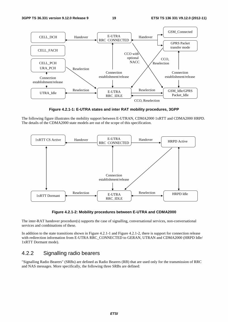
ETSI
ETSI TS 136 331 V9.12.0 (2012-11)193GPP TS 36.331 version 9.12.0 Release 9
Handover
CELL_PCH
URA_PCH
CELL_DCH
UTRA_Idle
E-UTRA RRC_CONNECTED
E-UTRA RRC_IDLE
GSM_Idle/GPRS Packet_Idle
GPRS Packet transfer mode
GSM_Connected
Handover
Reselection Reselection
Reselection
Connection establishment/release
Connection establishment/release
Connection establishment/release
CCO, Reselection
CCO with optional
NACC
CELL_FACH
CCO, Reselection
Figure 4.2.1-1: E-UTRA states and inter RAT mobility procedures, 3GPP
The following figure illustrates the mobility support between E-UTRAN, CDMA2000 1xRTT and CDMA2000 HRPD. The details of the CDMA2000 state models are out of the scope of this specification.
Handover 1xRTT CS Active
1xRTT Dormant
E-UTRA RRC_CONNECTED
E-UTRA RRC_IDLE
HRPD Idle
Handover
Reselection Reselection
Connection establishment/release
HRPD Dormant HRPD Active
Figure 4.2.1-2: Mobility procedures between E-UTRA and CDMA2000
The inter-RAT handover procedure(s) supports the case of signalling, conversational services, non-conversational services and combinations of these.
In addition to the state transitions shown in Figure 4.2.1-1 and Figure 4.2.1-2, there is support for connection release with redirection information from E-UTRA RRC_CONNECTED to GERAN, UTRAN and CDMA2000 (HRPD Idle/ 1xRTT Dormant mode).
4.2.2 Signalling radio bearers
"Signalling Radio Bearers" (SRBs) are defined as Radio Bearers (RB) that are used only for the transmission of RRC and NAS messages. More specifically, the following three SRBs are defined:
ETSI
ETSI TS 136 331 V9.12.0 (2012-11)203GPP TS 36.331 version 9.12.0 Release 9
- SRB0 is for RRC messages using the CCCH logical channel;
- SRB1 is for RRC messages (which may include a piggybacked NAS message) as well as for NAS messages prior to the establishment of SRB2, all using DCCH logical channel;
- SRB2 is for NAS messages, using DCCH logical channel. SRB2 has a lower-priority than SRB1 and is always configured by E-UTRAN after security activation.
In downlink piggybacking of NAS messages is used only for one dependant (i.e. with joint success/ failure) procedure: bearer establishment/ modification/ release. In uplink NAS message piggybacking is used only for transferring the initial NAS message during connection setup.
NOTE: The NAS messages transferred via SRB2 are also contained in RRC messages, which however do not include any RRC protocol control information.
Once security is activated, all RRC messages on SRB1 and SRB2, including those containing NAS or non-3GPP messages, are integrity protected and ciphered by PDCP. NAS independently applies integrity protection and ciphering to the NAS messages.
4.3 Services
4.3.1 Services provided to upper layers
The RRC protocol offers the following services to upper layers:
- Broadcast of common control information;
- Notification of UEs in RRC_IDLE, e.g. about a terminating call, for ETWS, for CMAS;
- Transfer of dedicated control information, i.e. information for one specific UE.
4.3.2 Services expected from lower layers
In brief, the following are the main services that RRC expects from lower layers:
- PDCP: integrity protection and ciphering;
- RLC: reliable and in-sequence transfer of information, without introducing duplicates and with support for segmentation and concatenation.
Further details about the services provided by Packet Data Convergence Protocol layer (e.g. integrity and ciphering) are provided in TS 36.323 [8]. The services provided by Radio Link Control layer (e.g. the RLC modes) are specified in TS 36.322 [7]. Further details about the services provided by Medium Access Control layer (e.g. the logical channels) are provided in TS 36.321 [6]. The services provided by physical layer (e.g. the transport channels) are specified in TS 36.302 [3].
4.4 Functions The RRC protocol includes the following main functions:
- Broadcast of system information:
- Including NAS common information;
- Information applicable for UEs in RRC_IDLE, e.g. cell (re-)selection parameters, neighbouring cell information and information (also) applicable for UEs in RRC_CONNECTED, e.g. common channel configuration information.
- Including ETWS notification, CMAS notification;
- RRC connection control:

ETSI
ETSI TS 136 331 V9.12.0 (2012-11)213GPP TS 36.331 version 9.12.0 Release 9
- Paging;
- Establishment/ modification/ release of RRC connection, including e.g. assignment/ modification of UE identity (C-RNTI), establishment/ modification/ release of SRB1 and SRB2, access class barring;
- Initial security activation, i.e. initial configuration of AS integrity protection (SRBs) and AS ciphering (SRBs, DRBs);
- RRC connection mobility including e.g. intra-frequency and inter-frequency handover, associated security handling, i.e. key/ algorithm change, specification of RRC context information transferred between network nodes;
- Establishment/ modification/ release of RBs carrying user data (DRBs);
- Radio configuration control including e.g. assignment/ modification of ARQ configuration, HARQ configuration, DRX configuration;
- QoS control including assignment/ modification of semi-persistent scheduling (SPS) configuration information for DL and UL, assignment/ modification of parameters for UL rate control in the UE, i.e. allocation of a priority and a prioritised bit rate (PBR) for each RB;
- Recovery from radio link failure;
- Inter-RAT mobility including e.g. security activation, transfer of RRC context information;
- Measurement configuration and reporting:
- Establishment/ modification/ release of measurements (e.g. intra-frequency, inter-frequency and inter- RAT measurements);
- Setup and release of measurement gaps;
- Measurement reporting;
- Other functions including e.g. transfer of dedicated NAS information and non-3GPP dedicated information, transfer of UE radio access capability information, support for E-UTRAN sharing (multiple PLMN identities);
- Generic protocol error handling;
- Support of self-configuration and self-optimisation;
NOTE: Random access is specified entirely in the MAC including initial transmission power estimation.
5 Procedures
5.1 General
5.1.1 Introduction
The procedural requirements are structured according to the main functional areas: system information (5.2), connection control (5.3), inter-RAT mobility (5.4) and measurements (5.5). In addition there is a sub-clause other (5.6) that covers e.g. NAS dedicated information transfer, UE capability transfer. Finally, sub-clause 5.7 specifies the generic error handling.
5.1.2 General requirements
The UE shall:
1> process the received messages in order of reception by RRC, i.e. the processing of a message shall be completed before starting the processing of a subsequent message;

ETSI
ETSI TS 136 331 V9.12.0 (2012-11)223GPP TS 36.331 version 9.12.0 Release 9
NOTE 1: E-UTRAN may initiate a subsequent procedure prior to receiving the UE's response of a previously initiated procedure.
1> within a sub-clause execute the steps according to the order specified in the procedural description;
1> consider the term 'radio bearer' (RB) to cover SRBs and DRBs but not MRBs unless explicitly stated otherwise;
1> set the rrc-TransactionIdentifier in the response message, if included, to the same value as included in the message received from E-UTRAN that triggered the response message;
1> upon receiving a choice value set to 'setup':
2> apply the corresponding received configuration and start using the associated resources, unless explicitly specified otherwise;
1> upon receiving a choice value set to 'release':
2> clear the corresponding configuration and stop using the associated resources;
1> upon handover to E-UTRA; or
1> upon receiving an RRCConnectionReconfiguration message including the fullConfig:
2> apply the Conditions in the ASN.1 for inclusion of the fields for the DRB/PDCP/RLC setup during the reconfiguration of the DRBs included in the drb-ToAddModList;
NOTE 2: At each point in time, the UE keeps a single value for each field except for during handover when the UE temporarily stores the previous configuration so it can revert back upon handover failure. In other words: when the UE reconfigures a field, the existing value is released except for during handover.
NOTE 3: Although not explicitly stated, the UE initially considers all functionality to be deactivated/ released until it is explicitly stated that the functionality is setup/ activated. Correspondingly, the UE initially considers lists to be empty e.g. the list of radio bearers, the list of measurements.
5.2 System information
5.2.1 Introduction
5.2.1.1 General
System information is divided into the MasterInformationBlock (MIB) and a number of SystemInformationBlocks (SIBs). The MIB includes a limited number of most essential and most frequently transmitted parameters that are needed to acquire other information from the cell, and is transmitted on BCH. SIBs other than SystemInformationBlockType1 are carried in SystemInformation (SI) messages and mapping of SIBs to SI messages is flexibly configurable by schedulingInfoList included in SystemInformationBlockType1, with restrictions that: each SIB is contained only in a single SI message, only SIBs having the same scheduling requirement (periodicity) can be mapped to the same SI message, and SystemInformationBlockType2 is always mapped to the SI message that corresponds to the first entry in the list of SI messages in schedulingInfoList. There may be multiple SI messages transmitted with the same periodicity. SystemInformationBlockType1 and all SI messages are transmitted on DL-SCH.
5.2.1.2 Scheduling
The MIB uses a fixed schedule with a periodicity of 40 ms and repetitions made within 40 ms. The first transmission of the MIB is scheduled in subframe #0 of radio frames for which the SFN mod 4 = 0, and repetitions are scheduled in subframe #0 of all other radio frames.
The SystemInformationBlockType1 uses a fixed schedule with a periodicity of 80 ms and repetitions made within 80 ms. The first transmission of SystemInformationBlockType1 is scheduled in subframe #5 of radio frames for which the SFN mod 8 = 0, and repetitions are scheduled in subframe #5 of all other radio frames for which SFN mod 2 = 0.
The SI messages are transmitted within periodically occurring time domain windows (referred to as SI-windows) using dynamic scheduling. Each SI message is associated with a SI-window and the SI-windows of different SI messages do

ETSI
ETSI TS 136 331 V9.12.0 (2012-11)233GPP TS 36.331 version 9.12.0 Release 9
not overlap. That is, within one SI-window only the corresponding SI is transmitted. The length of the SI-window is common for all SI messages, and is configurable. Within the SI-window, the corresponding SI message can be transmitted a number of times in any subframe other than MBSFN subframes, uplink subframes in TDD, and subframe #5 of radio frames for which SFN mod 2 = 0. The UE acquires the detailed time-domain scheduling (and other information, e.g. frequency-domain scheduling, used transport format) from decoding SI-RNTI on PDCCH (see TS 36.321 [6]).
A single SI-RNTI is used to address SystemInformationBlockType1 as well as all SI messages.
SystemInformationBlockType1 configures the SI-window length and the transmission periodicity for the SI messages.
5.2.1.3 System information validity and notification of changes
Change of system information (other than for ETWS and CMAS) only occurs at specific radio frames, i.e. the concept of a modification period is used. System information may be transmitted a number of times with the same content within a modification period, as defined by its scheduling. The modification period boundaries are defined by SFN values for which SFN mod m= 0, where m is the number of radio frames comprising the modification period. The modification period is configured by system information.
When the network changes (some of the) system information, it first notifies the UEs about this change, i.e. this may be done throughout a modification period. In the next modification period, the network transmits the updated system information. These general principles are illustrated in figure 5.2.1.3-1, in which different colours indicate different system information. Upon receiving a change notification, the UE acquires the new system information immediately from the start of the next modification period. The UE applies the previously acquired system information until the UE acquires the new system information.
BCCH modification period (n)
Change notification Updated information
BCCH modification period (n+1)
Figure 5.2.1.3-1: Change of system Information
The Paging message is used to inform UEs in RRC_IDLE and UEs in RRC_CONNECTED about a system information change. If the UE receives a Paging message including the systemInfoModification, it knows that the system information will change at the next modification period boundary. Although the UE may be informed about changes in system information, no further details are provided e.g. regarding which system information will change.
SystemInformationBlockType1 includes a value tag, systemInfoValueTag, that indicates if a change has occurred in the SI messages. UEs may use systemInfoValueTag, e.g. upon return from out of coverage, to verify if the previously stored SI messages are still valid. Additionally, the UE considers stored system information to be invalid after 3 hours from the moment it was successfully confirmed as valid, unless specified otherwise.
E-UTRAN may not update systemInfoValueTag upon change of some system information e.g. ETWS information, CMAS information, regularly changing parameters like CDMA2000 system time (see 6.3). Similarly, E-UTRAN may not include the systemInfoModification within the Paging message upon change of some system information.
The UE verifies that stored system information remains valid by either checking systemInfoValueTag in SystemInformationBlockType1 after the modification period boundary, or attempting to find the systemInfoModification indication at least modificationPeriodCoeff times during the modification period in case no paging is received, in every modification period. If no paging message is received by the UE during a modification period, the UE may assume that no change of system information will occur at the next modification period boundary. If UE in RRC_CONNECTED, during a modification period, receives one paging message, it may deduce from the presence/ absence of systemInfoModification whether a change of system information other than ETWS and CMAS information will occur in the next modification period or not.
ETWS and/or CMAS capable UEs in RRC_CONNECTED shall attempt to read paging at least once every defaultPagingCycle to check whether ETWS and/or CMAS notification is present or not.

ETSI
ETSI TS 136 331 V9.12.0 (2012-11)243GPP TS 36.331 version 9.12.0 Release 9
5.2.1.4 Indication of ETWS notification
ETWS primary notification and/ or ETWS secondary notification can occur at any point in time. The Paging message is used to inform ETWS capable UEs in RRC_IDLE and UEs in RRC_CONNECTED about presence of an ETWS primary notification and/ or ETWS secondary notification. If the UE receives a Paging message including the etws-Indication, it shall start receiving the ETWS primary notification and/ or ETWS secondary notification according to schedulingInfoList contained in SystemInformationBlockType1.
NOTE: The UE is not required to periodically check schedulingInfoList contained in SystemInformationBlockType1, but Paging message including the etws-Indication triggers the UE to re-acquire schedulingInfoList contained in SystemInformationBlockType1 for scheduling changes for SystemInformationBlockType10 and SystemInformationBlockType11. The UE may or may not receive a Paging message including the etws-Indication and/or systemInfoModification when ETWS is no longer scheduled.
ETWS primary notification is contained in SystemInformationBlockType10 and ETWS secondary notification is contained in SystemInformationBlockType11. Segmentation can be applied for the delivery of a secondary notification. The segmentation is fixed for transmission of a given secondary notification within a cell (i.e. the same segment size for a given segment with the same messageIdentifier, serialNumber and warningMessageSegmentNumber). An ETWS secondary notification corresponds to a single CB data IE as defined according to TS 23.041 [37].
5.2.1.5 Indication of CMAS notification
CMAS notification can occur at any point in time. The Paging message is used to inform CMAS capable UEs in RRC_IDLE and UEs in RRC_CONNECTED about presence of one or more CMAS notifications. If the UE receives a Paging message including the cmas-Indication, it shall start receiving the CMAS notifications according to schedulingInfoList contained in SystemInformationBlockType1.
NOTE: The UE is not required to periodically check schedulingInfoList contained in SystemInformationBlockType1, but Paging message including the cmas-Indication triggers the UE to re-acquire schedulingInfoList contained in SystemInformationBlockType1 for scheduling changes for SystemInformationBlockType12. The UE may or may not receive a Paging message including the cmas-Indication and/or systemInfoModification when SystemInformationBlockType12 is no longer scheduled.
CMAS notification is contained in SystemInformationBlockType12. Segmentation can be applied for the delivery of a CMAS notification. The segmentation is fixed for transmission of a given CMAS notification within a cell (i.e. the same segment size for a given segment with the same messageIdentifier, serialNumber and warningMessageSegmentNumber). E-UTRAN does not interleave transmissions of CMAS notifications, i.e. all segments of a given CMAS notification transmission are transmitted prior to those of another CMAS notification. A CMAS notification corresponds to a single CB data IE as defined according to TS 23.041 [37].
5.2.2 System information acquisition
5.2.2.1 General
E-UTRAN
MasterInformationBlock
UE
SystemInformationBlockType1
SystemInformation
Figure 5.2.2.1-1: System information acquisition, normal
The UE applies the system information acquisition procedure to acquire the AS- and NAS- system information that is broadcasted by the E-UTRAN. The procedure applies to UEs in RRC_IDLE and UEs in RRC_CONNECTED.

ETSI
ETSI TS 136 331 V9.12.0 (2012-11)253GPP TS 36.331 version 9.12.0 Release 9
5.2.2.2 Initiation
The UE shall apply the system information acquisition procedure upon selecting (e.g. upon power on) and upon re-selecting a cell, after handover completion, after entering E-UTRA from another RAT, upon return from out of coverage, upon receiving a notification that the system information has changed, upon receiving an indication about the presence of an ETWS notification, upon receiving an indication about the presence of a CMAS notification, upon receiving a request from CDMA2000 upper layers and upon exceeding the maximum validity duration. Unless explicitly stated otherwise in the procedural specification, the system information acquisition procedure overwrites any stored system information, i.e. delta configuration is not applicable for system information and the UE discontinues using a field if it is absent in system information unless explicitly specified otherwise.
5.2.2.3 System information required by the UE
The UE shall:
1> ensure having a valid version, as defined below, of (at least) the following system information, also referred to as the 'required' system information:
2> if in RRC_IDLE:
3> the MasterInformationBlock and SystemInformationBlockType1 as well as SystemInformationBlockType2 through SystemInformationBlockType8, depending on support of the concerned RATs;
2> if in RRC_CONNECTED:
3> the MasterInformationBlock, SystemInformationBlockType1 and SystemInformationBlockType2 as well as SystemInformationBlockType8, depending on support of CDMA2000;
1> delete any stored system information after 3 hours from the moment it was confirmed to be valid as defined in 5.2.1.3, unless specified otherwise;
1> consider any stored system information except SystemInformationBlockType10, SystemInformationBlockType11 and systemInformationBlockType12 to be invalid if systemInfoValueTag included in the SystemInformationBlockType1 is different from the one of the stored system information;
5.2.2.4 System information acquisition by the UE
The UE shall:
1> apply the specified BCCH configuration defined in 9.1.1.1;
1> if the procedure is triggered by a system information change notification:
2> start acquiring the required system information, as defined in 5.2.2.3, from the beginning of the modification period following the one in which the change notification was received;
NOTE 1: The UE continues using the previously received system information until the new system information has been acquired.
1> if the UE is in RRC_IDLE and enters a cell for which the UE does not have stored a valid version of the system information required in RRC_IDLE, as defined in 5.2.2.3:
2> acquire, using the system information acquisition procedure as defined in 5.2.3, the system information required in RRC_IDLE, as defined in 5.2.2.3;
1> following successful handover completion to a cell for which the UE does not have stored a valid version of the system information required in RRC_CONNECTED, as defined in 5.2.2.3:
2> acquire, using the system information acquisition procedure as defined in 5.2.3, the system information required in RRC_CONNECTED, as defined in 5.2.2.3;
2> upon acquiring the concerned system information:
3> discard the corresponding radio resource configuration information included in the radioResourceConfigCommon previously received in a dedicated message, if any;

ETSI
ETSI TS 136 331 V9.12.0 (2012-11)263GPP TS 36.331 version 9.12.0 Release 9
1> following a request from CDMA2000 upper layers:
2> acquire SystemInformationBlockType8, as defined in 5.2.3;
1> neither initiate the RRC connection establishment procedure nor initiate transmission of the RRCConnectionReestablishmentRequest message until the UE has a valid version of the MasterInformationBlock and SystemInformationBlockType1 messages as well as SystemInformationBlockType2 ;
1> if the UE is ETWS capable:
2> upon entering a cell during RRC_IDLE, following successful handover or upon connection re-establishment:
3> discard any previously buffered warningMessageSegment;
3> clear, if any, the current values of messageIdentifier and serialNumber for SystemInformationBlockType11;
2> when the UE acquires SystemInformationBlockType1 following ETWS indication, upon entering a cell during RRC_IDLE, following successful handover or upon connection re-establishment:
3> if schedulingInfoList indicates that SystemInformationBlockType10 is present:
4> start acquiring SystemInformationBlockType10 immediately;
3> if schedulingInfoList indicates that SystemInformationBlockType11 is present:
4> start acquiring SystemInformationBlockType11 immediately;
NOTE 2: UEs shall start acquiring SystemInformationBlockType10 and SystemInformationBlockType11 as described above even when systemInfoValueTag in SystemInformationBlockType1 has not changed.
1> if the UE is CMAS capable:
2> upon entering a cell during RRC_IDLE, following successful handover or upon connection re-establishment:
3> discard any previously buffered warningMessageSegment;
3> clear, if any, stored values of messageIdentifier and serialNumber for SystemInformationBlockType12 associated with the discarded warningMessageSegment ;
2> when the UE acquires SystemInformationBlockType1 following CMAS indication, upon entering a cell during RRC_IDLE, following successful handover and upon connection re-establishment:
3> if schedulingInfoList indicates that SystemInformationBlockType12 is present:
4> aquire SystemInformationBlockType12;
NOTE 3: UEs shall start acquiring SystemInformationBlockType12 as described above even when systemInfoValueTag in SystemInformationBlockType1 has not changed.
1> if the UE is interested to receive MBMS services; and
1> if schedulingInfoList indicates that SystemInformationBlockType13 is present and the UE does not have stored a valid version of this system information block:
2> aquire SystemInformationBlockType13;
The UE may apply the received SIBs immediately, i.e. the UE does not need to delay using a SIB until all SI messages have been received. The UE may delay applying the received SIBs until completing lower layer procedures associated with a received or a UE originated RRC message, e.g. an ongoing random access procedure.
NOTE 4: While attempting to acquire a particular SIB, if the UE detects from schedulingInfoList that it is no longer present, the UE should stop trying to acquire the particular SIB.
5.2.2.5 Essential system information missing
The UE shall

ETSI
ETSI TS 136 331 V9.12.0 (2012-11)273GPP TS 36.331 version 9.12.0 Release 9
1> if in RRC_IDLE or in RRC_CONNECTED while T311 is running:
2> if the UE is unable to acquire the MasterInformationBlock or the SystemInformationBlockType1:
3> consider the cell as barred in accordance with TS 36.304 [4] and;
3> perform barring as if intraFreqReselection is set to 'allowed', and as if the csg-Indication is set to 'FALSE';
2> else if the UE is unable to acquire the SystemInformationBlockType2:
3> treat the cell as barred in accordance with TS 36.304 [4];
5.2.2.6 Actions upon reception of the MasterInformationBlock message
Upon receiving the MasterInformationBlock message the UE shall:
1> apply the radio resource configuration included in the phich-Config;
1> if the UE is in RRC_IDLE or if the UE is in RRC_CONNECTED while T311 is running:
2> if the UE has no valid system information stored according to 5.2.2.3 for the concerned cell:
3> apply the received value of dl-Bandwidth to the ul-Bandwidth until SystemInformationBlockType2 is received;
5.2.2.7 Actions upon reception of the SystemInformationBlockType1 message
Upon receiving the SystemInformationBlockType1 message the UE shall:
1> if the frequency band indicated in the freqBandIndicator is part of the frequency bands supported by the UE; or
1> if the UE supports multiBandInfoList, and if one or more of the frequency bands indicated in the multiBandInfoList are part of the frequency bands supported by the UE:
2> forward the cellIdentity to upper layers;
2> forward the trackingAreaCode to upper layers;
1> else:
2> consider the cell as barred in accordance with TS 36.304 [4] and;
2> perform barring as if intraFreqReselection is set to notAllowed, and as if the csg-Indication is set to FALSE;
5.2.2.8 Actions upon reception of SystemInformation messages
No UE requirements related to the contents of the SystemInformation messages apply other than those specified elsewhere e.g. within procedures using the concerned system information, and/ or within the corresponding field descriptions.
5.2.2.9 Actions upon reception of SystemInformationBlockType2
Upon receiving SystemInformationBlockType2, the UE shall:
1> if upper layers indicate that a (UE specific) paging cycle is configured:
2> Apply the shortest of the (UE specific) paging cycle and the defaultPagingCycle included in the radioResourceConfigCommon;
1> else:
2> Apply the defaultPagingCycle included in the radioResourceConfigCommon;
1> if the mbsfn-SubframeConfigList is included:
ETSI
ETSI TS 136 331 V9.12.0 (2012-11)283GPP TS 36.331 version 9.12.0 Release 9
2> consider that no other DL assignments occur in the MBSFN subframes indicated in the mbsfn-SubframeConfigList:
1> apply the configuration included in the radioResourceConfigCommon;
1> apply the specified PCCH configuration defined in 9.1.1.3;
1> not apply the timeAlignmentTimerCommon;
1> if in RRC_CONNECTED and UE has previously received rlf-TimersAndConstants:
2> The UE shall not update its values of the timers and constants in UE-TimersAndConstants except for the value of timer T300.
5.2.2.10 Actions upon reception of SystemInformationBlockType3
No UE requirements related to the contents of this SystemInformationBlock apply other than those specified elsewhere e.g. within procedures using the concerned system information, and/ or within the corresponding field descriptions.
5.2.2.11 Actions upon reception of SystemInformationBlockType4
No UE requirements related to the contents of this SystemInformationBlock apply other than those specified elsewhere e.g. within procedures using the concerned system information, and/ or within the corresponding field descriptions.
5.2.2.12 Actions upon reception of SystemInformationBlockType5
No UE requirements related to the contents of this SystemInformationBlock apply other than those specified elsewhere e.g. within procedures using the concerned system information, and/ or within the corresponding field descriptions.
5.2.2.13 Actions upon reception of SystemInformationBlockType6
No UE requirements related to the contents of this SystemInformationBlock apply other than those specified elsewhere e.g. within procedures using the concerned system information, and/ or within the corresponding field descriptions.
5.2.2.14 Actions upon reception of SystemInformationBlockType7
No UE requirements related to the contents of this SystemInformationBlock apply other than those specified elsewhere e.g. within procedures using the concerned system information, and/ or within the corresponding field descriptions.
5.2.2.15 Actions upon reception of SystemInformationBlockType8
Upon receiving SystemInformationBlockType8, the UE shall:
1> if the systemTimeInfo is included:
2> forward the systemTimeInfo to CDMA2000 upper layers;
1> if the UE is in RRC_IDLE and if searchWindowSize is included:
2> forward the searchWindowSize to CDMA2000 upper layers;
1> if parametersHRPD is included;
2> forward the preRegistrationInfoHRPD to CDMA2000 upper layers only if the UE has not received the preRegistrationInfoHRPD within an RRCConnectionReconfiguration message after entering this cell;
2> if the cellReselectionParametersHRPD is included:
3> forward the neighCellList to the CDMA2000 upper layers;
1> if the parameters1XRTT is included:
2> if the csfb-RegistrationParam1XRTT is included:

ETSI
ETSI TS 136 331 V9.12.0 (2012-11)293GPP TS 36.331 version 9.12.0 Release 9
3> forward the csfb-RegistrationParam1XRTT to the CDMA2000 upper layers which will use this information to determine if a CS registration/re-registration towards CDMA2000 1xRTT in the EUTRA cell is required;
2> else:
3> indicate to CDMA2000 upper layers that CSFB Registration to CDMA2000 1xRTT is not allowed;
2> if the longCodeState1XRTT is included:
3> forward the longCodeState1XRTT to CDMA2000 upper layers;
2> if the cellReselectionParameters1XRTT is included:
3> forward the neighCellList to the CDMA2000 upper layers;
2> if the csfb-SupportForDualRxUEs is included:
3> forward csfb-SupportForDualRxUEs to the CDMA2000 upper layers;
2> else
3> forward csfb-SupportForDualRxUEs, with its value set to FALSE, to the CDMA2000 upper layers;
2> forward the ac-BarringConfig1XRTT to CDMA2000 upper layers, if included;
5.2.2.16 Actions upon reception of SystemInformationBlockType9
Upon receiving SystemInformationBlockType9, the UE shall:
1> if hnb-Name is included, forward the hnb-Name to upper layers;
5.2.2.17 Actions upon reception of SystemInformationBlockType10
Upon receiving SystemInformationBlockType10, the UE shall:
1> forward the received warningType, warningSecurityInfo (if present), messageIdentifier and serialNumber to upper layers;
5.2.2.18 Actions upon reception of SystemInformationBlockType11
Upon receiving SystemInformationBlockType11, the UE shall:
1> if there is no current value for messageIdentifier and serialNumber for SystemInformationBlockType11; or
1> if either the received value of messageIdentifier or of serialNumber or of both are different from the current values of messageIdentifier and serialNumber for SystemInformationBlockType11:
2> use the received values of messageIdentifier and serialNumber for SystemInformationBlockType11 as the current values of messageIdentifier and serialNumber for SystemInformationBlockType11;
2> discard any previously buffered warningMessageSegment;
2> if all segments of a warning message have been received:
3> assemble the warning message from the received warningMessageSegment;
3> forward the received warning message, messageIdentifier, serialNumber and dataCodingScheme to upper layers;
3> stop reception of SystemInformationBlockType11;
3> discard the current values of messageIdentifier and serialNumber for SystemInformationBlockType11;
2> else:
3> store the received warningMessageSegment;

ETSI
ETSI TS 136 331 V9.12.0 (2012-11)303GPP TS 36.331 version 9.12.0 Release 9
3> continue reception of SystemInformationBlockType11;
1> else if all segments of a warning message have been received:
2> assemble the warning message from the received warningMessageSegment;
2> forward the received complete warning message, messageIdentifier, serialNumber and dataCodingScheme to upper layers;
2> stop reception of SystemInformationBlockType11;
2> discard the current values of messageIdentifier and serialNumber for SystemInformationBlockType11;
1> else:
2> store the received warningMessageSegment;
2> continue reception of SystemInformationBlockType11;
The UE should discard any stored warningMessageSegment and the current value of messageIdentifier and serialNumber for SystemInformationBlockType11 if the complete warning message has not been assembled within a period of 3 hours.
5.2.2.19 Actions upon reception of SystemInformationBlockType12
Upon receiving SystemInformationBlockType12, the UE shall:
1> if the SystemInformationBlockType12 contains a complete warning message:
2> forward the received warning message, messageIdentifier, serialNumber and dataCodingScheme to upper layers;
2> continue reception of SystemInformationBlockType12;
1> else:
2> if the received values of messageIdentifier and serialNumber are the same (each value is the same) as a pair for which a warning message is currently being assembled:
3> store the received warningMessageSegment;
3> if all segments of a warning message have been received:
4> assemble the warning message from the received warningMessageSegment;
4> forward the received warning message, messageIdentifier, serialNumber and dataCodingScheme to upper layers;
4> stop assembling a warning message for this messageIdentifier and serialNumber and delete all stored information held for it;
3> continue reception of SystemInformationBlockType12;
2> else if the received values of messageIdentifier and/or serialNumber are not the same as any of the pairs for which a warning message is currently being assembled:
3> start assembling a warning message for this messageIdentifier and serialNumber pair;
3> store the received warningMessageSegment;
3> continue reception of SystemInformationBlockType12;
The UE should discard warningMessageSegment and the associated values of messageIdentifierand serialNumber for SystemInformationBlockType12 if the complete warning message has not been assembled within a period of 3 hours.
NOTE: The number of warning messages that a UE can re-assemble simultaneously is a function of UE implementation.

ETSI
ETSI TS 136 331 V9.12.0 (2012-11)313GPP TS 36.331 version 9.12.0 Release 9
5.2.2.20 Actions upon reception of SystemInformationBlockType13
No UE requirements related to the contents of this SystemInformationBlock apply other than those specified elsewhere e.g. within procedures using the concerned system information, and/ or within the corresponding field descriptions.
5.2.3 Acquisition of an SI message
When acquiring an SI message, the UE shall:
1> determine the start of the SI-window for the concerned SI message as follows:
2> for the concerned SI message, determine the number n which corresponds to the order of entry in the list of SI messages configured by schedulingInfoList in SystemInformationBlockType1;
2> determine the integer value x = (n – 1)*w, where w is the si-WindowLength;
2> the SI-window starts at the subframe #a, where a = x mod 10, in the radio frame for which SFN mod T = FLOOR(x/10), where T is the si-Periodicity of the concerned SI message;
NOTE: E-UTRAN should configure an SI-window of 1 ms only if all SIs are scheduled before subframe #5 in radio frames for which SFN mod 2 = 0.
1> receive DL-SCH using the SI-RNTI from the start of the SI-window and continue until the end of the SI-window whose absolute length in time is given by si-WindowLength, or until the SI message was received, excluding the following subframes:
2> subframe #5 in radio frames for which SFN mod 2 = 0;
2> any MBSFN subframes;
2> any uplink subframes in TDD;
1> if the SI message was not received by the end of the SI-window, repeat reception at the next SI-window occasion for the concerned SI message;
5.3 Connection control
5.3.1 Introduction
5.3.1.1 RRC connection control
RRC connection establishment involves the establishment of SRB1. E-UTRAN completes RRC connection establishment prior to completing the establishment of the S1 connection, i.e. prior to receiving the UE context information from the EPC. Consequently, AS security is not activated during the initial phase of the RRC connection. During this initial phase of the RRC connection, the E-UTRAN may configure the UE to perform measurement reporting. However, the UE only accepts a handover message when security has been activated.
Upon receiving the UE context from the EPC, E-UTRAN activates security (both ciphering and integrity protection) using the initial security activation procedure. The RRC messages to activate security (command and successful response) are integrity protected, while ciphering is started only after completion of the procedure. That is, the response to the message used to activate security is not ciphered, while the subsequent messages (e.g. used to establish SRB2 and DRBs) are both integrity protected and ciphered.
After having initiated the initial security activation procedure, E-UTRAN initiates the establishment of SRB2 and DRBs, i.e. E-UTRAN may do this prior to receiving the confirmation of the initial security activation from the UE. In any case, E-UTRAN will apply both ciphering and integrity protection for the RRC connection reconfiguration messages used to establish SRB2 and DRBs. E-UTRAN should release the RRC connection if the initial security activation and/ or the radio bearer establishment fails (i.e. security activation and DRB establishment are triggered by a joint S1-procedure, which does not support partial success).
For SRB2 and DRBs, security is always activated from the start, i.e. the E-UTRAN does not establish these bearers prior to activating security.
ETSI
ETSI TS 136 331 V9.12.0 (2012-11)323GPP TS 36.331 version 9.12.0 Release 9
The release of the RRC connection is initiated by E-UTRAN. The procedure may be used to re-direct the UE to an E-UTRA frequency or an inter-RAT carrier frequency. In exceptional cases the UE may abort the RRC connection, i.e. move to RRC_IDLE without notifying E-UTRAN.
5.3.1.2 Security
AS security comprises of the integrity protection of RRC signalling (SRBs) as well as the ciphering of RRC signalling (SRBs) and user data (DRBs).
RRC handles the configuration of the security parameters which are part of the AS configuration: the integrity protection algorithm, the ciphering algorithm and two parameters, namely the keyChangeIndicator and the nextHopChainingCount, which are used by the UE to determine the AS security keys upon handover and/ or connection re-establishment.
The integrity protection algorithm is common for signalling radio bearers SRB1 and SRB2. The ciphering algorithm is common for all radio bearers (i.e. SRB1, SRB2 and DRBs). Neither integrity protection nor ciphering applies for SRB0.
RRC integrity and ciphering are always activated together, i.e. in one message/ procedure. RRC integrity and ciphering are never de-activated. However, it is possible to switch to a 'NULL' ciphering algorithm (eea0).
The 'NULL' integrity protection algorithm (eia0) is used only for the UE in limited service mode [32, TS33.401]. In case the 'NULL' integrity protection algorithm is used, 'NULL' ciphering algorithm is also used.
NOTE 1: Lower layers discard RRC messages for which the integrity check has failed and indicate the integrity verification check failure to RRC.
The AS applies three different security keys: one for the integrity protection of RRC signalling (KRRCint), one for the ciphering of RRC signalling (KRRCenc) and one for the ciphering of user data (KUPenc). All three AS keys are derived from the KeNB key. The KeNB is based on the KASME key, which is handled by upper layers.
Upon connection establishment new AS keys are derived. No AS-parameters are exchanged to serve as inputs for the derivation of the new AS keys at connection establishment.
The integrity and ciphering of the RRC message used to perform handover is based on the security configuration used prior to the handover and is performed by the source eNB.
The integrity and ciphering algorithms can only be changed upon handover. The four AS keys (KeNB, KRRCint, KRRCenc
and KUPenc) change upon every handover and connection re-establishment. The keyChangeIndicator is used upon handover and indicates whether the UE should use the keys associated with the latest available KASME key. The nextHopChainingCount parameter is used upon handover and connection re-establishment by the UE when deriving the new KeNB that is used to generate KRRCint, KRRCenc and KUPenc (see TS 33.401 [32]). An intra cell handover procedure may be used to change the keys in RRC_CONNECTED.
For each radio bearer an independent counter (COUNT, as specified in TS 36.323 [8]) is maintained for each direction. For each DRB, the COUNT is used as input for ciphering. For each SRB, the COUNT is used as input for both ciphering and integrity protection. It is not allowed to use the same COUNT value more than once for a given security key. In order to limit the signalling overhead, individual messages/ packets include a short sequence number (PDCP SN, as specified in TS 36.323 [8]). In addition, an overflow counter mechanism is used: the hyper frame number (TX_HFN and RX_HFN, as specified in TS 36.323 [8]). The HFN needs to be synchronized between the UE and the eNB. The eNB is responsible for avoiding reuse of the COUNT with the same RB identity and with the same KeNB, e.g. due to the transfer of large volumes of data, release and establishment of new RBs. In order to avoid such re-use, the eNB may e.g. use different RB identities for successive RB establishments, trigger an intra cell handover or an RRC_CONNECTED to RRC_IDLE to RRC_CONNECTED transition.
For each SRB, the value provided by RRC to lower layers to derive the 5-bit BEARER parameter used as input for ciphering and for integrity protection is the value of the corresponding srb-Identity with the MSBs padded with zeroes.
5.3.1.3 Connected mode mobility
In RRC_CONNECTED, the network controls UE mobility, i.e. the network decides when the UE shall move to which cell (which may be on another frequency or RAT). For network controlled mobility in RRC_CONNECTED, handover is the only procedure that is defined. The network triggers the handover procedure e.g. based on radio conditions, load. To facilitate this, the network may configure the UE to perform measurement reporting (possibly including the

ETSI
ETSI TS 136 331 V9.12.0 (2012-11)333GPP TS 36.331 version 9.12.0 Release 9
configuration of measurement gaps). The network may also initiate handover blindly, i.e. without having received measurement reports from the UE.
Before sending the handover message to the UE, the source eNB prepares one or more target cells. The target eNB generates the message used to perform the handover, i.e. the message including the AS-configuration to be used in the target cell. The source eNB transparently (i.e. does not alter values/ content) forwards the handover message/ information received from the target to the UE. When appropriate, the source eNB may initiate data forwarding for (a subset of) the DRBs.
After receiving the handover message, the UE attempts to access the target cell at the first available RACH occasion according to Random Access resource selection defined in TS 36.321 [6], i.e. the handover is asynchronous. Consequently, when allocating a dedicated preamble for the random access in the target cell, E-UTRA shall ensure it is available from the first RACH occasion the UE may use. Upon successful completion of the handover, the UE sends a message used to confirm the handover.
If the target eNB does not support the release of RRC protocol which the source eNB used to configure the UE, the target eNB may be unable to comprehend the UE configuration provided by the source eNB. In this case, the target eNB should use the full configuration option to reconfigure the UE for Handover and Re-establishment. Full configuration option includes an initialization of the radio configuration, which makes the procedure independent of the configuration used in the source cell with the exception that the security algorithms are continued for the RRC re-establishment.
After the successful completion of handover, PDCP SDUs may be re-transmitted in the target cell. This only applies for DRBs using RLC-AM mode and for handovers not involving full configuration option. The further details are specified in TS 36.323 [8]. After the successful completion of handover not involving full configuration option, the SN and the HFN are reset except for the DRBs using RLC-AM mode (for which both SN and HFN continue). For reconfigurations involving the full configuration option, the PDCP entities are newly established (SN and HFN do not continue) for all DRBs irrespective of the RLC mode. The further details are specified in TS 36.323 [8].
One UE behaviour to be performed upon handover is specified, i.e. this is regardless of the handover procedures used within the network (e.g. whether the handover includes X2 or S1 signalling procedures).
The source eNB should, for some time, maintain a context to enable the UE to return in case of handover failure. After having detected handover failure, the UE attempts to resume the RRC connection either in the source or in another cell using the RRC re-establishment procedure. This connection resumption succeeds only if the accessed cell is prepared, i.e. concerns a cell of the source eNB or of another eNB towards which handover preparation has been performed.
Normal measurement and mobility procedures are used to support handover to cells broadcasting a CSG identity. In addition, E-UTRAN may configure the UE to report that it is entering or leaving the proximity of cell(s) included in its CSG whitelist. Furthermore, E-UTRAN may request the UE to provide additional information broadcast by the handover candidate cell e.g. cell global identity, CSG identity, CSG membership status.
NOTE E-UTRAN may use the ‘proximity report’ to configure measurements as well as to decide whether or not to request additional information broadcast by the handover candidate cell. The additional information is used to verify whether or not the UE is authorised to access the target cell and may also be needed to identify handover candidate cell (PCI confusion i.e. when the physical layer identity that is included in the measurement report does not uniquely identify the cell).
5.3.2 Paging
5.3.2.1 General
Paging
UE EUTRAN
Figure 5.3.2.1-1: Paging

ETSI
ETSI TS 136 331 V9.12.0 (2012-11)343GPP TS 36.331 version 9.12.0 Release 9
The purpose of this procedure is:
- to transmit paging information to a UE in RRC_IDLE and/ or;
- to inform UEs in RRC_IDLE and UEs in RRC_CONNECTED about a system information change and/ or;
- to inform about an ETWS primary notification and/ or ETWS secondary notification and/ or;
- to inform about a CMAS notification.
The paging information is provided to upper layers, which in response may initiate RRC connection establishment, e.g. to receive an incoming call.
5.3.2.2 Initiation
E-UTRAN initiates the paging procedure by transmitting the Paging message at the UE's paging occasion as specified in TS 36.304 [4]. E-UTRAN may address multiple UEs within a Paging message by including one PagingRecord for each UE. E-UTRAN may also indicate a change of system information, and/ or provide an ETWS notification or a CMAS notification in the Paging message.
5.3.2.3 Reception of the Paging message by the UE
Upon receiving the Paging message, the UE shall:
1> if in RRC_IDLE, for each of the PagingRecord, if any, included in the Paging message:
2> if the ue-Identity included in the PagingRecord matches one of the UE identities allocated by upper layers:
3> forward the ue-Identity and the cn-Domain to the upper layers;
1> if the systemInfoModification is included:
2> re-acquire the required system information using the system information acquisition procedure as specified in 5.2.2.
1> if the etws-Indication is included and the UE is ETWS capable:
2> re-acquire SystemInformationBlockType1 immediately, i.e., without waiting until the next system information modification period boundary;
2> if the schedulingInfoList indicates that SystemInformationBlockType10 is present:
3> acquire SystemInformationBlockType10;
2> if the schedulingInfoList indicates that SystemInformationBlockType11 is present:
3> acquire SystemInformationBlockType11;
1> if the cmas-Indication is included and the UE is CMAS capable:
2> re-acquire SystemInformationBlockType1 immediately, i.e., without waiting until the next system information modification period boundary as specified in 5.2.1.5;
2> if the schedulingInfoList indicates that SystemInformationBlockType12 is present:
3> acquire SystemInformationBlockType12;

ETSI
ETSI TS 136 331 V9.12.0 (2012-11)353GPP TS 36.331 version 9.12.0 Release 9
5.3.3 RRC connection establishment
5.3.3.1 General
RRCConnectionSetup
RRCConnectionRequest
UE EUTRAN
RRCConnectionSetupComplete
Figure 5.3.3.1-1: RRC connection establishment, successful
RRCConnectionReject
RRCConnectionRequest
UE EUTRAN
Figure 5.3.3.1-2: RRC connection establishment, network reject
The purpose of this procedure is to establish an RRC connection. RRC connection establishment involves SRB1 establishment. The procedure is also used to transfer the initial NAS dedicated information/ message from the UE to E-UTRAN.
E-UTRAN applies the procedure as follows:
- to establish SRB1 only.
5.3.3.2 Initiation
The UE initiates the procedure when upper layers request establishment of an RRC connection while the UE is in RRC_IDLE.
Upon initiation of the procedure, the UE shall:
1> if the UE is establishing the RRC connection for mobile terminating calls:
2> if timer T302 is running:
3> consider access to the cell as barred;
2> else:
3> consider access to the cell as not barred;
1> else if the UE is establishing the RRC connection for emergency calls:
2> if SystemInformationBlockType2 includes the ac-BarringInfo:

ETSI
ETSI TS 136 331 V9.12.0 (2012-11)363GPP TS 36.331 version 9.12.0 Release 9
3> if the ac-BarringForEmergency is set to FALSE:
4> consider access to the cell as not barred;
3> else if the UE has one or more Access Classes, as stored on the USIM, with a value in the range 11..15, which is valid for the UE to use according to TS 22.011 [10] and TS 23.122 [11]:
NOTE 1: ACs 12, 13, 14 are only valid for use in the home country and ACs 11, 15 are only valid for use in the HPLMN/ EHPLMN.
4> if the ac-BarringInfo includes ac-BarringForMO-Data, and for all of the valid Access Classes for the UE, the corresponding bit in the ac-BarringForSpecialAC contained in ac-BarringForMO-Data is set to one:
5> consider access to the cell as barred;
4> else:
5> consider access to the cell as not barred;
3> else:
4> consider access to the cell as barred;
2> else:
3> consider access to the cell as not barred;
1> else if the UE is establishing the RRC connection for mobile originating calls:
2> if timer T302 or T303 is running:
3> consider access to the cell as barred;
2> else if SystemInformationBlockType2 includes the ac-BarringInfo and the ac-BarringForMO-Data is present:
3> if the UE has one or more Access Classes, as stored on the USIM, with a value in the range 11..15, which is valid for the UE to use according to TS 22.011 [10] and TS 23.122 [11], and
3> for at least one of these Access Classes the corresponding bit in the ac-BarringForSpecialAC contained in ac-BarringForMO-Data is set to zero:
4> consider access to the cell as not barred;
3> else:
4> draw a random number 'rand' uniformly distributed in the range: 0 ≤ rand < 1;
4> if 'rand' is lower than the value indicated by ac-BarringFactor included in ac-BarringForMO-Data:
5> consider access to the cell as not barred;
4> else:
5> consider access to the cell as barred;
2> else:
3> consider access to the cell as not barred;
1> else (the UE is establishing the RRC connection for mobile originating signalling):
2> if timer T302 or T305 is running:
3> consider access to the cell as barred;
2> else if SystemInformationBlockType2 includes the ac-BarringInfo and the ac-BarringForMO-Signalling is present:
ETSI
ETSI TS 136 331 V9.12.0 (2012-11)373GPP TS 36.331 version 9.12.0 Release 9
3> if the UE has one or more Access Classes, as stored on the USIM, with a value in the range 11..15, which is valid for the UE to use according to TS 22.011 [10] and TS 23.122 [11], and
3> for at least one of these Access Classes the corresponding bit in the ac-BarringForSpecialAC contained in ac-BarringForMO-Signalling is set to zero:
4> consider access to the cell as not barred;
3> else:
4> draw a random number 'rand' uniformly distributed in the range: 0 ≤ rand < 1;
4> if 'rand' is lower than the value indicated by ac-BarringFactor included in ac-BarringForMO-Signalling:
5> consider access to the cell as not barred;
4> else:
5> consider access to the cell as barred;
2> else:
3> consider access to the cell as not barred;
1> if access to the cell, as specified above, is not barred:
2> apply the default physical channel configuration as specified in 9.2.4;
2> apply the default semi-persistent scheduling configuration as specified in 9.2.3;
2> apply the default MAC main configuration as specified in 9.2.2;
2> apply the CCCH configuration as specified in 9.1.1.2;
2> apply the timeAlignmentTimerCommon included in SystemInformationBlockType2;
2> start timer T300;
2> initiate transmission of the RRCConnectionRequest message in accordance with 5.3.3.3;
NOTE 2: Upon initiating the connection establishment procedure, the UE is not required to ensure it maintains up to date system information applicable only for UEs in RRC_IDLE state. However, the UE needs to perform system information acquisition upon cell re-selection.
1> else:
2> if the UE is establishing the RRC connection for mobile originating calls and if both timers T302 and T303 are not running:
3> draw a random number 'rand' that is uniformly distributed in the range 0 ≤ rand < 1;
3> start timer T303 with the timer value calculated as follows, using the ac-BarringTime included in ac-BarringForMO-Data:
T303= (0.7+ 0.6 * rand) * ac-BarringTime
3> inform upper layers about the failure to establish the RRC connection and that access barring for mobile originating calls is applicable, upon which the procedure ends;
2> else if the UE is establishing the RRC connection for mobile originating signalling and if both timers T302 and T305 are not running:
3> draw a random number 'rand' that is uniformly distributed in the range 0 ≤ rand < 1;
3> start timer T305 with the timer value calculated as follows, using the ac-BarringTime included in ac-BarringForMO-Signalling:

ETSI
ETSI TS 136 331 V9.12.0 (2012-11)383GPP TS 36.331 version 9.12.0 Release 9
T305= (0.7+ 0.6 * rand) * ac-BarringTime
3> inform upper layers about the failure to establish the RRC connection and that access barring for mobile originating signalling is applicable, upon which the procedure ends;
2> else if the UE is establishing the RRC connection for emergency calls:
3> inform upper layers about the failure to establish the RRC connection and that access barring for emergency calls is applicable, upon which the procedure ends;
2> else:
3> inform upper layers about the failure to establish the RRC connection, upon which the procedure ends;
5.3.3.3 Actions related to transmission of RRCConnectionRequest message
The UE shall set the contents of RRCConnectionRequest message as follows:
1> set the ue-Identity as follows:
2> if upper layers provide an S-TMSI:
3> set the ue-Identity to the value received from upper layers;
2> else:
3> draw a random value in the range 0 .. 240-1 and set the ue-Identity to this value;
NOTE 1: Upper layers provide the S-TMSI if the UE is registered in the TA of the current cell.
1> set the establishmentCause in accordance with the information received from upper layers;
The UE shall submit the RRCConnectionRequest message to lower layers for transmission.
The UE shall continue cell re-selection related measurements as well as cell re-selection evaluation. If the conditions for cell re-selection are fulfilled, the UE shall perform cell re-selection as specified in 5.3.3.5.
5.3.3.4 Reception of the RRCConnectionSetup by the UE
NOTE: Prior to this, lower layer signalling is used to allocate a C-RNTI. For further details see TS 36.321 [6];
The UE shall:
1> perform the radio resource configuration procedure in accordance with the received radioResourceConfigDedicated and as specified in 5.3.10;
1> if stored, discard the cell reselection priority information provided by the idleModeMobilityControlInfo or inherited from another RAT;
1> stop timer T300;
1> stop timer T302, if running;
1> stop timer T303, if running;
1> stop timer T305, if running;
1> perform the actions as specified in 5.3.3.7;
1> stop timer T320, if running;
1> enter RRC_CONNECTED;
1> stop the cell re-selection procedure;
1> set the content of RRCConnectionSetupComplete message as follows:

ETSI
ETSI TS 136 331 V9.12.0 (2012-11)393GPP TS 36.331 version 9.12.0 Release 9
2> set the selectedPLMN-Identity to the PLMN selected by upper layers (see TS 23.122 [11], TS 24.301 [35]) from the PLMN(s) included in the plmn-IdentityList in SystemInformationBlockType1;
2> if upper layers provide the 'Registered MME', include and set the registeredMME as follows:
3> if the PLMN identity of the 'Registered MME' is different from the PLMN selected by the upper layers:
4> include the plmnIdentity in the registeredMME and set it to the value of the PLMN identity in the 'Registered MME' received from upper layers;
3> set the mmegi and the mmec to the value received from upper layers;
2> set the dedicatedInfoNAS to include the information received from upper layers;
2> submit the RRCConnectionSetupComplete message to lower layers for transmission, upon which the procedure ends;
5.3.3.5 Cell re-selection while T300, T302, T303 or T305 is running
The UE shall:
1> if cell reselection occurs while T300, T302, T303 or T305 is running:
2> if timer T302, T303 and/ or T305 is running:
3> stop timer T302, T303 and T305, whichever ones were running;
3> perform the actions as specified in 5.3.3.7;
2> if timer T300 is running:
3> stop timer T300;
3> reset MAC, release the MAC configuration and re-establish RLC for all RBs that are established;
3> inform upper layers about the failure to establish the RRC connection, upon which the procedure ends;
5.3.3.6 T300 expiry
The UE shall:
1> if timer T300 expires:
2> reset MAC, release the MAC configuration and re-establish RLC for all RBs that are established;
2> inform upper layers about the failure to establish the RRC connection, upon which the procedure ends;
5.3.3.7 T302, T303 or T305 expiry or stop
The UE shall:
1> if timer T302 expires or is stopped:
2> inform upper layers about barring alleviation for mobile terminating access;
2> if timer T303 is not running:
3> inform upper layers about barring alleviation for mobile originating calls;
2> if timer T305 is not running:
3> inform upper layers about barring alleviation for mobile originating signalling;
1> if timer T303 expires or is stopped:
2> if timer T302 is not running:

ETSI
ETSI TS 136 331 V9.12.0 (2012-11)403GPP TS 36.331 version 9.12.0 Release 9
3> inform upper layers about barring alleviation for mobile originating calls;
1> if timer T305 expires or is stopped:
2> if timer T302 is not running:
3> inform upper layers about barring alleviation for mobile originating signalling;
5.3.3.8 Reception of the RRCConnectionReject by the UE
The UE shall:
1> stop timer T300;
1> reset MAC and release the MAC configuration;
1> start timer T302, with the timer value set to the waitTime;
1> inform upper layers about the failure to establish the RRC connection and that access barring for mobile originating calls, mobile originating signalling and mobile terminating access is applicable, upon which the procedure ends;
5.3.3.9 Abortion of RRC connection establishment
If upper layers abort the RRC connection establishment procedure while the UE has not yet entered RRC_CONNECTED, the UE shall:
1> stop timer T300, if running;
1> reset MAC, release the MAC configuration and re-establish RLC for all RBs that are established;
5.3.3.10 Handling of SSAC related parameters
Upon request from the upper layers, the UE shall:
1> set the local variables BarringFactorForMMTEL-Voice and BarringTimeForMMTEL-Voice as follows:
2> if the UE is in RRC_IDLE and ssac-BarringForMMTEL-Voice is present:
3> if the UE has one or more Access Classes, as stored on the USIM, with a value in the range 11..15, which is valid for the UE to use according to TS 22.011 [10] and TS 23.122 [11], and
NOTE: ACs 12, 13, 14 are only valid for use in the home country and ACs 11, 15 are only valid for use in the HPLMN/ EHPLMN.
3> if, for at least one of these Access Classes, the corresponding bit in the ac-BarringForSpecialAC contained in ssac-BarringForMMTEL-Voice is set to zero:
4> set BarringFactorForMMTEL-Voice to one and BarringTimeForMMTEL-Voice to zero;
3> else:
4> set BarringFactorForMMTEL-Voice and BarringTimeForMMTEL-Voice to the value of ac-BarringFactor and ac-BarringTime included in ssac-BarringForMMTEL-Voice, respectively;
2> else set BarringFactorForMMTEL-Voice to one and BarringTimeForMMTEL-Voice to zero;
1> set the local variables BarringFactorForMMTEL-Video and BarringTimeForMMTEL-Video as follows:
2> if the UE is in RRC_IDLE and ssac-BarringForMMTEL-Video is present:
3> if the UE has one or more Access Classes, as stored on the USIM, with a value in the range 11..15, which is valid for the UE to use according to TS 22.011 [10] and TS 23.122 [11], and
3> if, for at least one of these Access Classes, the corresponding bit in the ac-BarringForSpecialAC contained in ssac-BarringForMMTEL-Video is set to zero:
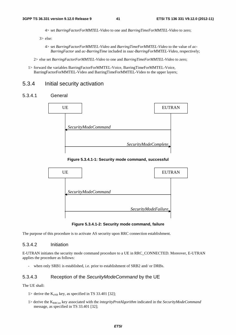
ETSI
ETSI TS 136 331 V9.12.0 (2012-11)413GPP TS 36.331 version 9.12.0 Release 9
4> set BarringFactorForMMTEL-Video to one and BarringTimeForMMTEL-Video to zero;
3> else:
4> set BarringFactorForMMTEL-Video and BarringTimeForMMTEL-Video to the value of ac-BarringFactor and ac-BarringTime included in ssac-BarringForMMTEL-Video, respectively;
2> else set BarringFactorForMMTEL-Video to one and BarringTimeForMMTEL-Video to zero;
1> forward the variables BarringFactorForMMTEL-Voice, BarringTimeForMMTEL-Voice, BarringFactorForMMTEL-Video and BarringTimeForMMTEL-Video to the upper layers;
5.3.4 Initial security activation
5.3.4.1 General
SecurityModeComplete
SecurityModeCommand
UE EUTRAN
Figure 5.3.4.1-1: Security mode command, successful
SecurityModeFailure
SecurityModeCommand
UE EUTRAN
Figure 5.3.4.1-2: Security mode command, failure
The purpose of this procedure is to activate AS security upon RRC connection establishment.
5.3.4.2 Initiation
E-UTRAN initiates the security mode command procedure to a UE in RRC_CONNECTED. Moreover, E-UTRAN applies the procedure as follows:
- when only SRB1 is established, i.e. prior to establishment of SRB2 and/ or DRBs.
5.3.4.3 Reception of the SecurityModeCommand by the UE
The UE shall:
1> derive the KeNB key, as specified in TS 33.401 [32];
1> derive the KRRCint key associated with the integrityProtAlgorithm indicated in the SecurityModeCommand message, as specified in TS 33.401 [32];

ETSI
ETSI TS 136 331 V9.12.0 (2012-11)423GPP TS 36.331 version 9.12.0 Release 9
1> request lower layers to verify the integrity protection of the SecurityModeCommand message, using the algorithm indicated by the integrityProtAlgorithm as included in the SecurityModeCommand message and the KRRCint key;
1> if the SecurityModeCommand message passes the integrity protection check:
2> derive the KRRCenc key and the KUPenc key associated with the cipheringAlgorithm indicated in the SecurityModeCommand message, as specified in TS 33.401 [32];
2> configure lower layers to apply integrity protection using the indicated algorithm and the KRRCint key immediately, i.e. integrity protection shall be applied to all subsequent messages received and sent by the UE, including the SecurityModeComplete message;
2> configure lower layers to apply ciphering using the indicated algorithm, the KRRCenc key and the KUPenc key after completing the procedure, i.e. ciphering shall be applied to all subsequent messages received and sent by the UE, except for the SecurityModeComplete message which is sent unciphered;
2> consider AS security to be activated;
2> submit the SecurityModeComplete message to lower layers for transmission, upon which the procedure ends;
1> else:
2> continue using the configuration used prior to the reception of the SecurityModeCommand message, i.e. neither apply integrity protection nor ciphering.
2> submit the SecurityModeFailure message to lower layers for transmission, upon which the procedure ends;
5.3.5 RRC connection reconfiguration
5.3.5.1 General
RRCConnectionReconfigurationComplete
RRCConnectionReconfiguration
UE EUTRAN
Figure 5.3.5.1-1: RRC connection reconfiguration, successful
RRC connection re-establishment
RRCConnectionReconfiguration
UE EUTRAN
Figure 5.3.5.1-2: RRC connection reconfiguration, failure

ETSI
ETSI TS 136 331 V9.12.0 (2012-11)433GPP TS 36.331 version 9.12.0 Release 9
The purpose of this procedure is to modify an RRC connection, e.g. to establish/ modify/ release RBs, to perform handover, to setup/ modify/ release measurements. As part of the procedure, NAS dedicated information may be transferred from E-UTRAN to the UE.
5.3.5.2 Initiation
E-UTRAN may initiate the RRC connection reconfiguration procedure to a UE in RRC_CONNECTED. E-UTRAN applies the procedure as follows:
- the mobilityControlInfo is included only when AS-security has been activated, and SRB2 with at least one DRB are setup and not suspended;
- the establishment of RBs (other than SRB1, that is established during RRC connection establishment) is included only when AS security has been activated;
5.3.5.3 Reception of an RRCConnectionReconfiguration not including the mobilityControlInfo by the UE
If the RRCConnectionReconfiguration message does not include the mobilityControlInfo and the UE is able to comply with the configuration included in this message, the UE shall:
1> if this is the first RRCConnectionReconfiguration message after successful completion of the RRC Connection Re-establishment procedure:
2> re-establish PDCP for SRB2 and for all DRBs that are established, if any;
2> re-establish RLC for SRB2 and for all DRBs that are established, if any;
2> if the RRCConnectionReconfiguration message includes the fullConfig:
3> perform the radio configuration procedure as specified in section 5.3.5.8;
2> if the RRCConnectionReconfiguration message includes the radioResourceConfigDedicated:
3> perform the radio resource configuration procedure as specified in 5.3.10;
2> resume SRB2 and all DRBs that are suspended, if any;
NOTE 1: The handling of the radio bearers after the successful completion of the PDCP re-establishment, e.g. the re-transmission of unacknowledged PDCP SDUs (as well as the associated status reporting), the handling of the SN and the HFN, is specified in TS 36.323 [8].
1> else:
2> if the RRCConnectionReconfiguration message includes the radioResourceConfigDedicated:
3> perform the radio resource configuration procedure as specified in 5.3.10;
NOTE 2: If the RRCConnectionReconfiguration message includes the establishment of radio bearers other than SRB1, the UE may start using these radio bearers immediately, i.e. there is no need to wait for an outstanding acknowledgment of the SecurityModeComplete message.
1> if the RRCConnectionReconfiguration message includes the dedicatedInfoNASList:
2> forward each element of the dedicatedInfoNASList to upper layers in the same order as listed;
1> if the RRCConnectionReconfiguration message includes the measConfig:
2> perform the measurement configuration procedure as specified in 5.5.2;
1> if the RRCConnectionReconfiguration message includes the reportProximityConfig:
2> perform the proximity indication in accordance with the received reportProximityConfig;
1> submit the RRCConnectionReconfigurationComplete message to lower layers for transmission using the new configuration, upon which the procedure ends;
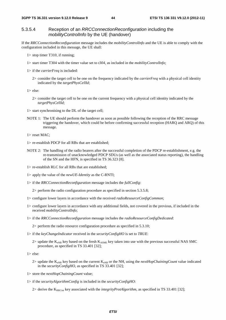
ETSI
ETSI TS 136 331 V9.12.0 (2012-11)443GPP TS 36.331 version 9.12.0 Release 9
5.3.5.4 Reception of an RRCConnectionReconfiguration including the mobilityControlInfo by the UE (handover)
If the RRCConnectionReconfiguration message includes the mobilityControlInfo and the UE is able to comply with the configuration included in this message, the UE shall:
1> stop timer T310, if running;
1> start timer T304 with the timer value set to t304, as included in the mobilityControlInfo;
1> if the carrierFreq is included:
2> consider the target cell to be one on the frequency indicated by the carrierFreq with a physical cell identity indicated by the targetPhysCellId;
1> else:
2> consider the target cell to be one on the current frequency with a physical cell identity indicated by the targetPhysCellId;
1> start synchronising to the DL of the target cell;
NOTE 1: The UE should perform the handover as soon as possible following the reception of the RRC message triggering the handover, which could be before confirming successful reception (HARQ and ARQ) of this message.
1> reset MAC;
1> re-establish PDCP for all RBs that are established;
NOTE 2: The handling of the radio bearers after the successful completion of the PDCP re-establishment, e.g. the re-transmission of unacknowledged PDCP SDUs (as well as the associated status reporting), the handling of the SN and the HFN, is specified in TS 36.323 [8].
1> re-establish RLC for all RBs that are established;
1> apply the value of the newUE-Identity as the C-RNTI;
1> if the RRCConnectionReconfiguration message includes the fullConfig:
2> perform the radio configuration procedure as specified in section 5.3.5.8;
1> configure lower layers in accordance with the received radioResourceConfigCommon;
1> configure lower layers in accordance with any additional fields, not covered in the previous, if included in the received mobilityControlInfo;
1> if the RRCConnectionReconfiguration message includes the radioResourceConfigDedicated:
2> perform the radio resource configuration procedure as specified in 5.3.10;
1> if the keyChangeIndicator received in the securityConfigHO is set to TRUE:
2> update the KeNB key based on the fresh KASME key taken into use with the previous successful NAS SMC procedure, as specified in TS 33.401 [32];
1> else:
2> update the KeNB key based on the current KeNB or the NH, using the nextHopChainingCount value indicated in the securityConfigHO, as specified in TS 33.401 [32];
1> store the nextHopChainingCount value;
1> if the securityAlgorithmConfig is included in the securityConfigHO:
2> derive the KRRCint key associated with the integrityProtAlgorithm, as specified in TS 33.401 [32];

ETSI
ETSI TS 136 331 V9.12.0 (2012-11)453GPP TS 36.331 version 9.12.0 Release 9
2> derive the KRRCenc key and the KUPenc key associated with the cipheringAlgorithm, as specified in TS 33.401 [32];
1> else:
2> derive the KRRCint key associated with the current integrity algorithm, as specified in TS 33.401 [32];
2> derive the KRRCenc key and the KUPenc key associated with the current ciphering algorithm, as specified in TS 33.401 [32];
1> configure lower layers to apply the integrity protection algorithm and the KRRCint key, i.e. the integrity protection configuration shall be applied to all subsequent messages received and sent by the UE, including the message used to indicate the successful completion of the procedure;
1> configure lower layers to apply the ciphering algorithm, the KRRCenc key and the KUPenc key, i.e. the ciphering configuration shall be applied to all subsequent messages received and sent by the UE, including the message used to indicate the successful completion of the procedure;
1> perform the measurement related actions as specified in 5.5.6.1;
1> if the RRCConnectionReconfiguration message includes the measConfig:
2> perform the measurement configuration procedure as specified in 5.5.2;
1> release reportProximityConfig and clear any associated proximity status reporting timer;
1> if the RRCConnectionReconfiguration message includes the reportProximityConfig:
2> perform the proximity indication in accordance with the received reportProximityConfig;
1> submit the RRCConnectionReconfigurationComplete message to lower layers for transmission;
1> if MAC successfully completes the random access procedure:
2> stop timer T304;
2> apply the parts of the CQI reporting configuration, the scheduling request configuration and the sounding RS configuration that do not require the UE to know the SFN of the target cell, if any;
2> apply the parts of the measurement and the radio resource configuration that require the UE to know the SFN of the target cell (e.g. measurement gaps, periodic CQI reporting, scheduling request configuration, sounding RS configuration), if any, upon acquiring the SFN of the target cell;
NOTE 3: Whenever the UE shall setup or reconfigure a configuration in accordance with a field that is received it applies the new configuration, except for the cases addressed by the above statements.
2> the procedure ends;
NOTE 4: The UE is not required to determine the SFN of the target cell by acquiring system information from that cell before performing RACH access in the target cell.
5.3.5.5 Reconfiguration failure
The UE shall:
1> if the UE is unable to comply with (part of) the configuration included in the RRCConnectionReconfiguration message:
2> continue using the configuration used prior to the reception of RRCConnectionReconfiguration message;
2> if security has not been activated:
3> perform the actions upon leaving RRC_CONNECTED as specified in 5.3.12, with release cause 'other';
2> else:
ETSI
ETSI TS 136 331 V9.12.0 (2012-11)463GPP TS 36.331 version 9.12.0 Release 9
3> initiate the connection re-establishment procedure as specified in 5.3.7, upon which the connection reconfiguration procedure ends;
NOTE 1: The UE may apply above failure handling also in case the RRCConnectionReconfiguration message causes a protocol error for which the generic error handling as defined in 5.7 specifies that the UE shall ignore the message.
NOTE 2: If the UE is unable to comply with part of the configuration, it does not apply any part of the configuration, i.e. there is no partial success/ failure.
5.3.5.6 T304 expiry (handover failure)
The UE shall:
1> if T304 expires (handover failure):
NOTE: Following T304 expiry any dedicated preamble, if provided within the rach-ConfigDedicated, is not available for use by the UE anymore.
2> revert back to the configuration used in the source cell, excluding the configuration configured by the physicalConfigDedicated, the mac-MainConfig and the sps-Config;
2> initiate the connection re-establishment procedure as specified in 5.3.7, upon which the RRC connection reconfiguration procedure ends;
5.3.5.7 Void
5.3.5.8 Radio Configuration involving full configuration option
The UE shall:
1> release/ clear all current dedicated radio configurations except the C-RNTI, the security configuration and the PDCP, RLC and logical channel configurations for the RBs;
NOTE 1: Radio configuration is not just the resource configuration but includes other configurations like MeasConfig and OtherConfig.
1> if the RRCConnectionReconfiguration message includes the mobilityControlInfo:
2> release/ clear all current common radio configurations;
2> use the default values specified in 9.2.5 for timer T310, T311 and constant N310, N311;
1> else:
2> use values for timers T301, T310, T311 and constants N310, N311, as included in ue-TimersAndConstants received in SystemInformationBlockType2;
1> apply the default physical channel configuration as specified in 9.2.4;
1> apply the default semi-persistent scheduling configuration as specified in 9.2.3;
1> apply the default MAC main configuration as specified in 9.2.2;
1> for each srb-Identity value included in the srb-ToAddModList (SRB reconfiguration):
2> apply the specified configuration defined in 9.1.2 for the corresponding SRB;
2> apply the corresponding default RLC configuration for the SRB specified in 9.2.1.1 for SRB1 or in 9.2.1.2 for SRB2;
2> apply the corresponding default logical channel configuration for the SRB as specified in 9.2.1.1 for SRB1 or in 9.2.1.2 for SRB2;
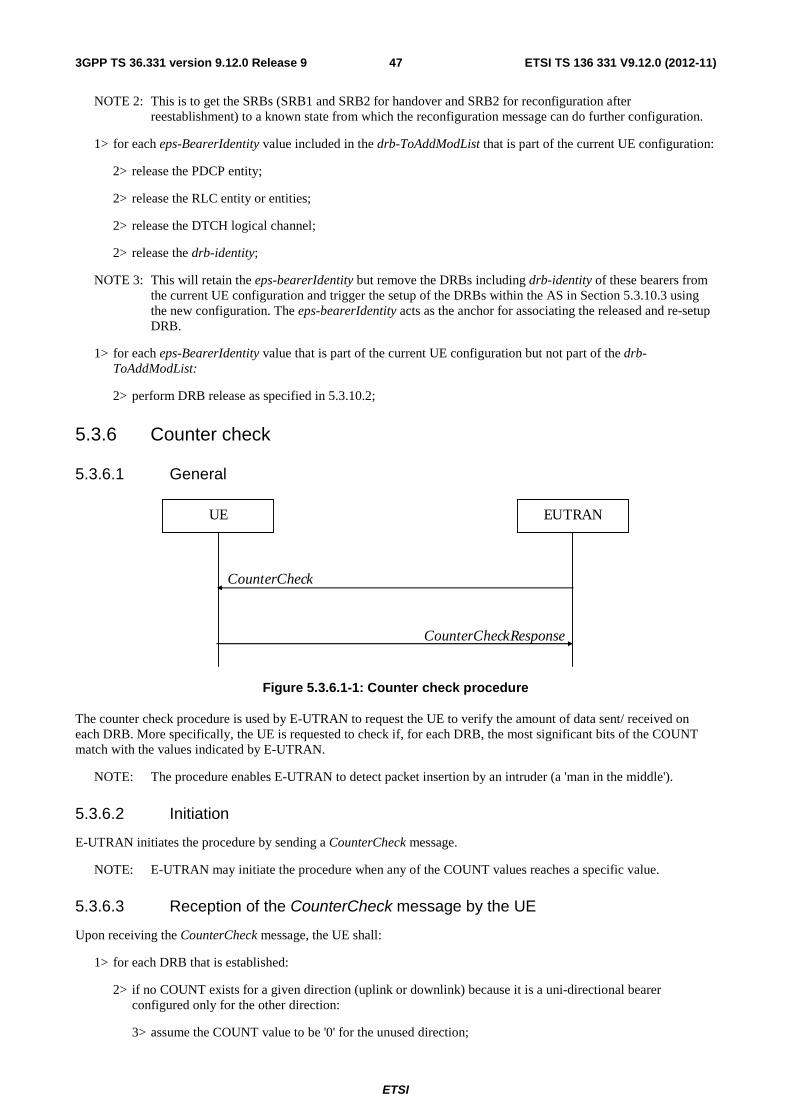
ETSI
ETSI TS 136 331 V9.12.0 (2012-11)473GPP TS 36.331 version 9.12.0 Release 9
NOTE 2: This is to get the SRBs (SRB1 and SRB2 for handover and SRB2 for reconfiguration after reestablishment) to a known state from which the reconfiguration message can do further configuration.
1> for each eps-BearerIdentity value included in the drb-ToAddModList that is part of the current UE configuration:
2> release the PDCP entity;
2> release the RLC entity or entities;
2> release the DTCH logical channel;
2> release the drb-identity;
NOTE 3: This will retain the eps-bearerIdentity but remove the DRBs including drb-identity of these bearers from the current UE configuration and trigger the setup of the DRBs within the AS in Section 5.3.10.3 using the new configuration. The eps-bearerIdentity acts as the anchor for associating the released and re-setup DRB.
1> for each eps-BearerIdentity value that is part of the current UE configuration but not part of the drb-ToAddModList:
2> perform DRB release as specified in 5.3.10.2;
5.3.6 Counter check
5.3.6.1 General
CounterCheckResponse
CounterCheck
UE EUTRAN
Figure 5.3.6.1-1: Counter check procedure
The counter check procedure is used by E-UTRAN to request the UE to verify the amount of data sent/ received on each DRB. More specifically, the UE is requested to check if, for each DRB, the most significant bits of the COUNT match with the values indicated by E-UTRAN.
NOTE: The procedure enables E-UTRAN to detect packet insertion by an intruder (a 'man in the middle').
5.3.6.2 Initiation
E-UTRAN initiates the procedure by sending a CounterCheck message.
NOTE: E-UTRAN may initiate the procedure when any of the COUNT values reaches a specific value.
5.3.6.3 Reception of the CounterCheck message by the UE
Upon receiving the CounterCheck message, the UE shall:
1> for each DRB that is established:
2> if no COUNT exists for a given direction (uplink or downlink) because it is a uni-directional bearer configured only for the other direction:
3> assume the COUNT value to be '0' for the unused direction;
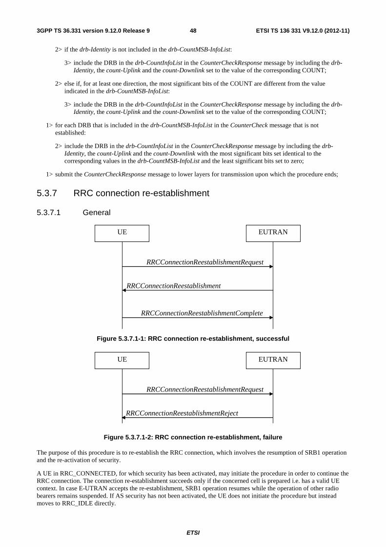
ETSI
ETSI TS 136 331 V9.12.0 (2012-11)483GPP TS 36.331 version 9.12.0 Release 9
2> if the drb-Identity is not included in the drb-CountMSB-InfoList:
3> include the DRB in the drb-CountInfoList in the CounterCheckResponse message by including the drb-Identity, the count-Uplink and the count-Downlink set to the value of the corresponding COUNT;
2> else if, for at least one direction, the most significant bits of the COUNT are different from the value indicated in the drb-CountMSB-InfoList:
3> include the DRB in the drb-CountInfoList in the CounterCheckResponse message by including the drb-Identity, the count-Uplink and the count-Downlink set to the value of the corresponding COUNT;
1> for each DRB that is included in the drb-CountMSB-InfoList in the CounterCheck message that is not established:
2> include the DRB in the drb-CountInfoList in the CounterCheckResponse message by including the drb-Identity, the count-Uplink and the count-Downlink with the most significant bits set identical to the corresponding values in the drb-CountMSB-InfoList and the least significant bits set to zero;
1> submit the CounterCheckResponse message to lower layers for transmission upon which the procedure ends;
5.3.7 RRC connection re-establishment
5.3.7.1 General
RRCConnectionReestablishmentRequest
UE EUTRAN
RRCConnectionReestablishment
RRCConnectionReestablishmentComplete
Figure 5.3.7.1-1: RRC connection re-establishment, successful
RRCConnectionReestablishmentRequest
UE EUTRAN
RRCConnectionReestablishmentReject
Figure 5.3.7.1-2: RRC connection re-establishment, failure
The purpose of this procedure is to re-establish the RRC connection, which involves the resumption of SRB1 operation and the re-activation of security.
A UE in RRC_CONNECTED, for which security has been activated, may initiate the procedure in order to continue the RRC connection. The connection re-establishment succeeds only if the concerned cell is prepared i.e. has a valid UE context. In case E-UTRAN accepts the re-establishment, SRB1 operation resumes while the operation of other radio bearers remains suspended. If AS security has not been activated, the UE does not initiate the procedure but instead moves to RRC_IDLE directly.
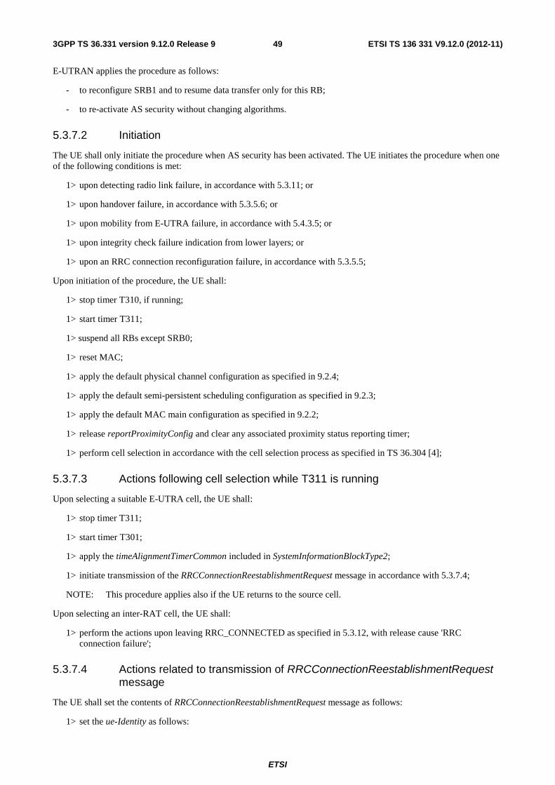
ETSI
ETSI TS 136 331 V9.12.0 (2012-11)493GPP TS 36.331 version 9.12.0 Release 9
E-UTRAN applies the procedure as follows:
- to reconfigure SRB1 and to resume data transfer only for this RB;
- to re-activate AS security without changing algorithms.
5.3.7.2 Initiation
The UE shall only initiate the procedure when AS security has been activated. The UE initiates the procedure when one of the following conditions is met:
1> upon detecting radio link failure, in accordance with 5.3.11; or
1> upon handover failure, in accordance with 5.3.5.6; or
1> upon mobility from E-UTRA failure, in accordance with 5.4.3.5; or
1> upon integrity check failure indication from lower layers; or
1> upon an RRC connection reconfiguration failure, in accordance with 5.3.5.5;
Upon initiation of the procedure, the UE shall:
1> stop timer T310, if running;
1> start timer T311;
1> suspend all RBs except SRB0;
1> reset MAC;
1> apply the default physical channel configuration as specified in 9.2.4;
1> apply the default semi-persistent scheduling configuration as specified in 9.2.3;
1> apply the default MAC main configuration as specified in 9.2.2;
1> release reportProximityConfig and clear any associated proximity status reporting timer;
1> perform cell selection in accordance with the cell selection process as specified in TS 36.304 [4];
5.3.7.3 Actions following cell selection while T311 is running
Upon selecting a suitable E-UTRA cell, the UE shall:
1> stop timer T311;
1> start timer T301;
1> apply the timeAlignmentTimerCommon included in SystemInformationBlockType2;
1> initiate transmission of the RRCConnectionReestablishmentRequest message in accordance with 5.3.7.4;
NOTE: This procedure applies also if the UE returns to the source cell.
Upon selecting an inter-RAT cell, the UE shall:
1> perform the actions upon leaving RRC_CONNECTED as specified in 5.3.12, with release cause 'RRC connection failure';
5.3.7.4 Actions related to transmission of RRCConnectionReestablishmentRequest message
The UE shall set the contents of RRCConnectionReestablishmentRequest message as follows:
1> set the ue-Identity as follows:

ETSI
ETSI TS 136 331 V9.12.0 (2012-11)503GPP TS 36.331 version 9.12.0 Release 9
2> set the c-RNTI to the C-RNTI used in the source cell (handover and mobility from E-UTRA failure) or used in the cell in which the trigger for the re-establishment occurred (other cases);
2> set the physCellId to the physical cell identity of the source cell (handover and mobility from E-UTRA failure) or of the cell in which the trigger for the re-establishment occurred (other cases);
2> set the shortMAC-I to the 16 least significant bits of the MAC-I calculated:
3> over the ASN.1 encoded as per section 8 (i.e., a multiple of 8 bits) VarShortMAC-Input;
3> with the KRRCint key and integrity protection algorithm that was used in the source cell (handover and mobility from E-UTRA failure) or of the cell in which the trigger for the re-establishment occurred (other cases); and
3> with all input bits for COUNT, BEARER and DIRECTION set to binary ones;
1> set the reestablishmentCause as follows:
2> if the re-establishment procedure was initiated due to reconfiguration failure as specified in 5.3.5.5 (the UE is unable to comply with the reconfiguration):
3> set the reestablishmentCause to the value 'reconfigurationFailure';
2> else if the re-establishment procedure was initiated due to handover failure as specified in 5.3.5.6 (intra-LTE handover failure) or 5.4.3.5 (inter-RAT mobility from EUTRA failure):
3> set the reestablishmentCause to the value 'handoverFailure';
2> else:
3> set the reestablishmentCause to the value 'otherFailure';
The UE shall submit the RRCConnectionReestablishmentRequest message to lower layers for transmission.
5.3.7.5 Reception of the RRCConnectionReestablishment by the UE
NOTE: Prior to this, lower layer signalling is used to allocate a C-RNTI. For further details see TS 36.321 [6];
The UE shall:
1> stop timer T301;
1> re-establish PDCP for SRB1;
1> re-establish RLC for SRB1;
1> perform the radio resource configuration procedure in accordance with the received radioResourceConfigDedicated and as specified in 5.3.10;
1> resume SRB1;
NOTE: E-UTRAN should not transmit any message on SRB1 prior to receiving the RRCConnectionReestablishmentComplete message.
1> update the KeNB key based on the KASME key to which the current KeNB is associated, using the nextHopChainingCount value indicated in the RRCConnectionReestablishment message, as specified in TS 33.401 [32];
1> store the nextHopChainingCount value;
1> derive the KRRCint key associated with the previously configured integrity algorithm, as specified in TS 33.401 [32];
1> derive the KRRCenc key and the KUPenc key associated with the previously configured ciphering algorithm, as specified in TS 33.401 [32];

ETSI
ETSI TS 136 331 V9.12.0 (2012-11)513GPP TS 36.331 version 9.12.0 Release 9
1> configure lower layers to activate integrity protection using the previously configured algorithm and the KRRCint key immediately, i.e., integrity protection shall be applied to all subsequent messages received and sent by the UE, including the message used to indicate the successful completion of the procedure;
1> configure lower layers to apply ciphering using the previously configured algorithm, the KRRCenc key and the KUPenc key immediately, i.e., ciphering shall be applied to all subsequent messages received and sent by the UE, including the message used to indicate the successful completion of the procedure;
1> set the content of RRCConnectionReestablishmentComplete message as follows:
2> include the rlf-InfoAvailable and set it to true, if the UE has radio link failure information available that is related to the last occurrence of radio link failure;
1> perform the measurement related actions as specified in 5.5.6.1;
1> submit the RRCConnectionReestablishmentComplete message to lower layers for transmission, upon which the procedure ends;
5.3.7.6 T311 expiry
Upon T311 expiry, the UE shall:
1> perform the actions upon leaving RRC_CONNECTED as specified in 5.3.12, with release cause 'RRC connection failure';
5.3.7.7 T301 expiry or selected cell no longer suitable
The UE shall:
1> if timer T301 expires; or
1> if the selected cell becomes no longer suitable according to the cell selection criteria as specified in TS 36.304 [4]:
2> perform the actions upon leaving RRC_CONNECTED as specified in 5.3.12, with release cause 'RRC connection failure';
5.3.7.8 Reception of RRCConnectionReestablishmentReject by the UE
Upon receiving the RRCConnectionReestablishmentReject message, the UE shall:
1> perform the actions upon leaving RRC_CONNECTED as specified in 5.3.12, with release cause 'RRC connection failure';
5.3.8 RRC connection release
5.3.8.1 General
RRCConnectionRelease
UE EUTRAN
Figure 5.3.8.1-1: RRC connection release, successful
The purpose of this procedure is to release the RRC connection, which includes the release of the established radio bearers as well as all radio resources.

ETSI
ETSI TS 136 331 V9.12.0 (2012-11)523GPP TS 36.331 version 9.12.0 Release 9
5.3.8.2 Initiation
E-UTRAN initiates the RRC connection release procedure to a UE in RRC_CONNECTED.
5.3.8.3 Reception of the RRCConnectionRelease by the UE
The UE shall:
1> delay the following actions defined in this sub-clause 60 ms from the moment the RRCConnectionRelease message was received or optionally when lower layers indicate that the receipt of the RRCConnectionRelease message has been successfully acknowledged, whichever is earlier;
1> if the RRCConnectionRelease message includes the idleModeMobilityControlInfo:
2> store the cell reselection priority information provided by the idleModeMobilityControlInfo;
2> if the t320 is included:
3> start timer T320, with the timer value set according to the value of t320;
1> else:
2> apply the cell reselection priority information broadcast in the system information;
1> if the releaseCause received in the RRCConnectionRelease message indicates 'loadBalancingTAURequired':
2> perform the actions upon leaving RRC_CONNECTED as specified in 5.3.12, with release cause 'load balancing TAU required';
1> else:
2> perform the actions upon leaving RRC_CONNECTED as specified in 5.3.12, with release cause 'other';
5.3.8.4 T320 expiry
The UE shall:
1> if T320 expires:
2> if stored, discard the cell reselection priority information provided by the idleModeMobilityControlInfo or inherited from another RAT;
2> apply the cell reselection priority information broadcast in the system information;
5.3.9 RRC connection release requested by upper layers
5.3.9.1 General
The purpose of this procedure is to release the RRC connection. Access to the current cell may be barred as a result of this procedure.
NOTE: Upper layers invoke the procedure, e.g. upon determining that the network has failed an authentication check, see TS 24.301 [35].
5.3.9.2 Initiation
The UE initiates the procedure when upper layers request the release of the RRC connection.
The UE shall:
1> perform the actions upon leaving RRC_CONNECTED as specified in 5.3.12, with release cause 'other';
1> if the upper layers indicate barring of the serving cell:

ETSI
ETSI TS 136 331 V9.12.0 (2012-11)533GPP TS 36.331 version 9.12.0 Release 9
2> treat the cell used prior to entering RRC_IDLE as barred according to TS 36.304 [4];
5.3.10 Radio resource configuration
5.3.10.0 General
The UE shall:
1> if the received radioResourceConfigDedicated includes the srb-ToAddModList:
2> perform the SRB addition or reconfiguration as specified in 5.3.10.1;
1> if the received radioResourceConfigDedicated includes the drb-ToReleaseList:
2> perform DRB release as specified in 5.3.10.2;
1> if the received radioResourceConfigDedicated includes the drb-ToAddModList:
2> perform DRB addition or reconfiguration as specified in 5.3.10.3;
1> if the received radioResourceConfigDedicated includes the mac-MainConfig:
2> perform MAC main reconfiguration as specified in 5.3.10.4;
1> if the received radioResourceConfigDedicated includes sps-Config:
2> perform SPS reconfiguration according to 5.3.10.5;
1> if the received radioResourceConfigDedicated includes the physicalConfigDedicated:
2> reconfigure the physical channel configuration as specified in 5.3.10. 6.
1> if the received radioResourceConfigDedicated includes the rlf-TimersAndConstants:
2> reconfigure the values of timers and constants as specified in 5.3.10.7;
5.3.10.1 SRB addition/ modification
The UE shall:
1> for each srb-Identity value included in the srb-ToAddModList that is not part of the current UE configuration (SRB establishment):
2> apply the specified configuration defined in 9.1.2 for the corresponding SRB;
2> establish a PDCP entity and configure it with the current security configuration, if applicable;
2> establish an RLC entity in accordance with the received rlc-Config;
2> establish a DCCH logical channel in accordance with the received logicalChannelConfig and with the logical channel identity set in accordance with 9.1.2;
1> for each srb-Identity value included in the srb-ToAddModList that is part of the current UE configuration (SRB reconfiguration):
2> reconfigure the RLC entity in accordance with the received rlc-Config;
2> reconfigure the DCCH logical channel in accordance with the received logicalChannelConfig;
5.3.10.2 DRB release
The UE shall:
1> for each drb-Identity value included in the drb-ToReleaseList that is part of the current UE configuration (DRB release); or
ETSI
ETSI TS 136 331 V9.12.0 (2012-11)543GPP TS 36.331 version 9.12.0 Release 9
1> for each drb-identity value that is to be released as the result of full configuration option according to 5.3.5.8:
2> release the PDCP entity;
2> release the RLC entity or entities;
2> release the DTCH logical channel;
1> if the procedure was triggered due to handover:
2> indicate the release of the DRB(s) and the eps-BearerIdentity of the released DRB(s) to upper layers after successful handover;
1> else:
2> indicate the release of the DRB(s) and the eps-BearerIdentity of the released DRB(s) to upper layers immediately.
NOTE: The UE does not consider the message as erroneous if the drb-ToReleaseList includes any drb-Identity value that is not part of the current UE configuration.
5.3.10.3 DRB addition/ modification
The UE shall:
1> for each drb-Identity value included in the drb-ToAddModList that is not part of the current UE configuration (DRB establishment including the case when full configuration option is used):
2> establish a PDCP entity and configure it with the current security configuration and in accordance with the received pdcp-Config;
2> establish an RLC entity or entities in accordance with the received rlc-Config;
2> establish a DTCH logical channel in accordance with the received logicalChannelIdentity and the received logicalChannelConfig;
1> if the RRCConnectionReconfiguration message includes the fullConfig IE:
2> associate the established DRB with corresponding included eps-BearerIdentity;
1> else:
2> indicate the establishment of the DRB(s) and the eps-BearerIdentity of the established DRB(s) to upper layers;
1> for each drb-Identity value included in the drb-ToAddModList that is part of the current UE configuration (DRB reconfiguration):
2> if the pdcp-Config is included:
3> reconfigure the PDCP entity in accordance with the received pdcp-Config;
2> if the rlc-Config is included:
3> reconfigure the RLC entity or entities in accordance with the received rlc-Config;
2> if the logicalChannelConfig is included:
3> reconfigure the DTCH logical channel in accordance with the received logicalChannelConfig;
NOTE: Removal and addition of the same drb-Identity in single radioResourceConfiguration is not supported.
5.3.10.4 MAC main reconfiguration
The UE shall:

ETSI
ETSI TS 136 331 V9.12.0 (2012-11)553GPP TS 36.331 version 9.12.0 Release 9
1> reconfigure the MAC main configuration in accordance with the received mac-MainConfig;
5.3.10.5 Semi-persistent scheduling reconfiguration
The UE shall:
1> reconfigure the semi-persistent scheduling in accordance with the received sps-Config:
5.3.10.6 Physical channel reconfiguration
The UE shall:
1> reconfigure the physical channel configuration in accordance with the received physicalConfigDedicated;
1> if the antennaInfo is included and set to 'explicitValue':
2> if the configured transmissionMode is not 'tm3' or 'tm4' or 'tm8':
3> release ri-ConfigIndex in cqi-ReportPeriodic, if previously configured;
2> if the configured transmissionMode is 'tm8' and pmi-RI-Report is not present:
3> release ri-ConfigIndex in cqi-ReportPeriodic, if previously configured;
1> else if the antennaInfo is included and set to 'defaultValue':
2> release ri-ConfigIndex in cqi-ReportPeriodic, if previously configured;
5.3.10.7 Radio Link Failure Timers and Constants reconfiguration
The UE shall:
1> if the received rlf-TimersAndConstants is set to ‘release’:
2> use values for timers T301, T310, T311 and constants N310, N311, as included in ue-TimersAndConstants received in SystemInformationBlockType2;
1> else:
2> reconfigure the value of timers and constants in accordance with received rlf-TimersAndConstants;
5.3.11 Radio link failure related actions
5.3.11.1 Detection of physical layer problems in RRC_CONNECTED
The UE shall:
1> upon receiving N310 consecutive "out-of-sync" indications from lower layers while neither T300, T301, T304 nor T311 is running:
2> start timer T310;
5.3.11.2 Recovery of physical layer problems
Upon receiving N311 consecutive "in-sync" indications from lower layers while T310 is running, the UE shall:
1> stop timer T310;
NOTE 1: In this case, the UE maintains the RRC connection without explicit signalling, i.e. the UE maintains the entire radio resource configuration.
NOTE 2: Periods in time where neither "in-sync" nor "out-of-sync" is reported by layer 1 do not affect the evaluation of the number of consecutive "in-sync" or "out-of-sync" indications.

ETSI
ETSI TS 136 331 V9.12.0 (2012-11)563GPP TS 36.331 version 9.12.0 Release 9
5.3.11.3 Detection of radio link failure
The UE shall:
1> upon T310 expiry; or
1> upon random access problem indication from MAC while neither T300, T301, T304 nor T311 is running; or
1> upon indication from RLC that the maximum number of retransmissions has been reached:
2> consider radio link failure to be detected;
2> if AS security has not been activated:
3> perform the actions upon leaving RRC_CONNECTED as specified in 5.3.12, with release cause 'other';
2> else:
3> initiate the connection re-establishment procedure as specified in 5.3.7;
5.3.12 UE actions upon leaving RRC_CONNECTED
Upon leaving RRC_CONNECTED, the UE shall:
1> reset MAC;
1> stop all timers that are running except T320;
1> release all radio resources, including release of the RLC entity, the MAC configuration and the associated PDCP entity for all established RBs;
1> indicate the release of the RRC connection to upper layers together with the release cause;
1> if leaving RRC_CONNECTED was not triggered by reception of the MobilityFromEUTRACommand message:
2> enter RRC_IDLE and perform procedures as specified in TS 36.304 [4, 5.2.7];
5.3.13 UE actions upon PUCCH/ SRS release request
Upon receiving a PUCCH/ SRS release request from lower layers, the UE shall:
1> apply the default physical channel configuration for CQI-ReportConfig and cqi-Mask if configured as specified in 9.2.4;
1> apply the default physical channel configuration for soundingRS-UL-ConfigDedicated as specified in 9.2.4;
1> apply the default physical channel configuration for schedulingRequestConfig as specified in 9.2.4;

ETSI
ETSI TS 136 331 V9.12.0 (2012-11)573GPP TS 36.331 version 9.12.0 Release 9
5.3.14 Proximity indication
5.3.14.1 General
ProximityIndication
UE EUTRAN
RRC connection reconfiguration
Figure 5.3.14.1-1: Proximity indication
The purpose of this procedure is to indicate that the UE is entering or leaving the proximity of one or more CSG member cells. The detection of proximity is based on an autonomous search function as defined in TS 36.304 [4].
5.3.14.2 Initiation
A UE in RRC_CONNECTED shall:
1> if the UE enters the proximity of one or more CSG member cell(s) on an E-UTRA frequency while proximity indication is enabled for such E-UTRA cells; or
1> if the UE enters the proximity of one or more CSG member cell(s) on an UTRA frequency while proximity indication is enabled for such UTRA cells; or
1> if the UE leaves the proximity of all CSG member cell(s) on an E-UTRA frequency while proximity indication is enabled for such E-UTRA cells; or
1> if the UE leaves the proximity of all CSG member cell(s) on an UTRA frequency while proximity indication is enabled for such UTRA cells:
2> if the UE has previously not transmitted a ProximityIndication for the RAT and frequency during the current RRC connection, or if more than 5 s has elapsed since the UE has last transmitted a ProximityIndication (either entering or leaving) for the RAT and frequency:
3> initiate transmission of the ProximityIndication message in accordance with 5.3.14.3;
NOTE: In the conditions above, "if the UE enters the proximity of one or more CSG member cell(s)" includes the case of already being in the proximity of such cell(s) at the time proximity indication for the corresponding RAT is enabled.
5.3.14.3 Actions related to transmission of ProximityIndication message
The UE shall set the contents of ProximityIndication message as follows:
1> if the UE applies the procedure to report entering the proximity of CSG member cell(s):
2> set type to 'entering';
1> else if the UE applies the procedure to report leaving the proximity of CSG member cell(s):
2> set type to 'leaving';
1> if the proximity indication was triggered for one or more CSG member cell(s) on an E-UTRA frequency:
2> set the carrierFreq to 'eutra' with the value set to the E-ARFCN value of the E-UTRA cell(s) for which proximity indication was triggered;

ETSI
ETSI TS 136 331 V9.12.0 (2012-11)583GPP TS 36.331 version 9.12.0 Release 9
1> else if the proximity indication was triggered for one or more CSG member cell(s) on a UTRA frequency:
2> set the carrierFreq to 'utra' with the value set to the ARFCN value of the UTRA cell(s) for which proximity indication was triggered;
The UE shall submit the ProximityIndication message to lower layers for transmission.
5.4 Inter-RAT mobility
5.4.1 Introduction
The general principles of connected mode mobility are described in 5.3.1.3. The general principles of the security handling upon connected mode mobility are described in 5.3.1.2.
For the (network controlled) inter RAT mobility from E-UTRA for a UE in RRC_CONNECTED, a single procedure is defined that supports both handover, cell change order with optional network assistance (NACC) and enhanced CS fallback to CDMA2000 1xRTT. In case of mobility to CDMA2000, the eNB decides when to move to the other RAT while the target RAT determines to which cell the UE shall move.
5.4.2 Handover to E-UTRA
5.4.2.1 General
RRCConnectionReconfigurationComplete
RRCConnectionReconfiguration (sent via other RAT)
UE EUTRAN
Figure 5.4.2.1-1: Handover to E-UTRA, successful
The purpose of this procedure is to, under the control of the network, transfer a connection between the UE and another Radio Access Network (e.g. GERAN or UTRAN) to E-UTRAN.
The handover to E-UTRA procedure applies when SRBs, possibly in combination with DRBs, are established in another RAT. Handover from UTRAN to E-UTRAN applies only after integrity has been activated in UTRAN.
5.4.2.2 Initiation
The RAN using another RAT initiates the Handover to E-UTRA procedure, in accordance with the specifications applicable for the other RAT, by sending the RRCConnectionReconfiguration message via the radio access technology from which the inter-RAT handover is performed.
E-UTRAN applies the procedure as follows:
- to activate ciphering, possibly using NULL algorithm, if not yet activated in the other RAT;
- to establish SRB1, SRB2 and one or more DRBs, i.e. at least the DRB associated with the default EPS bearer is established;
5.4.2.3 Reception of the RRCConnectionReconfiguration by the UE
If the UE is able to comply with the configuration included in the RRCConnectionReconfiguration message, the UE shall:

ETSI
ETSI TS 136 331 V9.12.0 (2012-11)593GPP TS 36.331 version 9.12.0 Release 9
1> apply the default physical channel configuration as specified in 9.2.4;
1> apply the default semi-persistent scheduling configuration as specified in 9.2.3;
1> apply the default MAC main configuration as specified in 9.2.2;
1> start timer T304 with the timer value set to t304, as included in the mobilityControlInfo;
1> consider the target cell to be one on the frequency indicated by the carrierFreq with a physical cell identity indicated by the targetPhysCellId;
1> start synchronising to the DL of the target cell;
1> set the C-RNTI to the value of the newUE-Identity;
1> for the target cell, apply the downlink bandwidth indicated by the dl-Bandwidth;
1> for the target cell, apply the uplink bandwidth indicated by (the absence or presence of) the ul-Bandwidth;
1> configure lower layers in accordance with the received radioResourceConfigCommon;
1> configure lower layers in accordance with any additional fields, not covered in the previous, if included in the received mobilityControlInfo;
1> perform the radio resource configuration procedure as specified in 5.3.10;
1> forward the nas-SecurityParamToEUTRA to the upper layers;
1> derive the KeNB key, as specified in TS 33.401 [32];
1> derive the KRRCint key associated with the integrityProtAlgorithm, as specified in TS 33.401 [32];
1> derive the KRRCenc key and the KUPenc key associated with the cipheringAlgorithm, as specified in TS 33.401 [32];
1> configure lower layers to apply the indicated integrity protection algorithm and the KRRCint key immediately, i.e. the indicated integrity protection configuration shall be applied to all subsequent messages received and sent by the UE, including the message used to indicate the successful completion of the procedure;
1> configure lower layers to apply the indicated ciphering algorithm, the KRRCenc key and the KUPenc key immediately, i.e. the indicated ciphering configuration shall be applied to all subsequent messages received and sent by the UE, including the message used to indicate the successful completion of the procedure;
1> if the RRCConnectionReconfiguration message includes the measConfig:
2> perform the measurement configuration procedure as specified in 5.5.2;
1> if the RRCConnectionReconfiguration message includes the reportProximityConfig:
2> perform the proximity indication configuration in accordance with the received reportProximityConfig;
1> submit the RRCConnectionReconfigurationComplete message to lower layers for transmission using the new configuration;
1> if the RRCConnectionReconfiguration message does not include the rlf-TimersAndConstants:
2> use the default values specified in 9.2.5 for timer T310, T311 and constant N310, N311;
1> if MAC successfully completes the random access procedure:
2> stop timer T304;
2> apply the parts of the CQI reporting configuration, the scheduling request configuration and the sounding RS configuration that do not require the UE to know the SFN of the target cell, if any;
2> apply the parts of the measurement and the radio resource configuration that require the UE to know the SFN of the target cell (e.g. measurement gaps, periodic CQI reporting, scheduling request configuration, sounding RS configuration), if any, upon acquiring the SFN of the target cell;

ETSI
ETSI TS 136 331 V9.12.0 (2012-11)603GPP TS 36.331 version 9.12.0 Release 9
NOTE 1: Whenever the UE shall setup or reconfigure a configuration in accordance with a field that is received it applies the new configuration, except for the cases addressed by the above statements.
2> enter E-UTRA RRC_CONNECTED, upon which the procedure ends;
NOTE 2: The UE is not required to determine the SFN of the target cell by acquiring system information from that cell before performing RACH access in the target cell.
5.4.2.4 Reconfiguration failure
The UE shall:
1> if the UE is unable to comply with (part of) the configuration included in the RRCConnectionReconfiguration message:
2> perform the actions defined for this failure case as defined in the specifications applicable for the other RAT;
NOTE 1: The UE may apply above failure handling also in case the RRCConnectionReconfiguration message causes a protocol error for which the generic error handling as defined in 5.7 specifies that the UE shall ignore the message.
NOTE 2: If the UE is unable to comply with part of the configuration, it does not apply any part of the configuration, i.e. there is no partial success/ failure.
5.4.2.5 T304 expiry (handover to E-UTRA failure)
The UE shall:
1> upon T304 expiry (handover to E-UTRA failure):
2> reset MAC;
2> perform the actions defined for this failure case as defined in the specifications applicable for the other RAT;
5.4.3 Mobility from E-UTRA
5.4.3.1 General
MobilityFromEUTRACommand
UE EUTRAN
Figure 5.4.3.1-1: Mobility from E-UTRA, successful
RRC connection re-establishment
MobilityFromEUTRACommand
UE EUTRAN
Figure 5.4.3.1-2: Mobility from E-UTRA, failure
ETSI
ETSI TS 136 331 V9.12.0 (2012-11)613GPP TS 36.331 version 9.12.0 Release 9
The purpose of this procedure is to move a UE in RRC_CONNECTED to a cell using another Radio Access Technology (RAT), e.g. GERAN, UTRA or CDMA2000 systems. The mobility from E-UTRA procedure covers the following type of mobility:
- handover, i.e. the MobilityFromEUTRACommand message includes radio resources that have been allocated for the UE in the target cell;
- cell change order, i.e. the MobilityFromEUTRACommand message may include information facilitating access of and/ or connection establishment in the target cell, e.g. system information. Cell change order is applicable only to GERAN; and
- enhanced CS fallback to CDMA2000 1xRTT, i.e. the MobilityFromEUTRACommand message includes radio resources that have been allocated for the UE in the target cell. The enhanced CS fallback to CDMA2000 1xRTT may be combined with concurrent handover or redirection to CDMA2000 HRPD.
5.4.3.2 Initiation
E-UTRAN initiates the mobility from E-UTRA procedure to a UE in RRC_CONNECTED, possibly in response to a MeasurementReport message or in response to reception of CS fallback indication for the UE from MME, by sending a MobilityFromEUTRACommand message. E-UTRAN applies the procedure as follows:
- the procedure is initiated only when AS-security has been activated, and SRB2 with at least one DRB are setup and not suspended;
5.4.3.3 Reception of the MobilityFromEUTRACommand by the UE
The UE shall be able to receive a MobilityFromEUTRACommand message and perform a cell change order to GERAN, even if no prior UE measurements have been performed on the target cell.
The UE shall:
1> stop timer T310, if running;
1> if the MobilityFromEUTRACommand message includes the purpose set to 'handover':
2> if the targetRAT-Type is set to 'utra' or 'geran':
3> consider inter-RAT mobility as initiated towards the RAT indicated by the targetRAT-Type included in the MobilityFromEUTRACommand message;
3> forward the nas-SecurityParamFromEUTRA to the upper layers;
3> access the target cell indicated in the inter-RAT message in accordance with the specifications of the target RAT;
3> if the targetRAT-Type is set to 'geran':
4> use the contents of systemInformation, if provided for PS Handover, as the system information to begin access on the target GERAN cell;
NOTE 1: If there are DRBs for which no radio bearers are established in the target RAT as indicated in the targetRAT-MessageContainer in the message, the E-UTRA RRC part of the UE does not indicate the release of the concerned DRBs to the upper layers. Upper layers may derive which bearers are not established from information received from the AS of the target RAT.
NOTE 2: In case of SR-VCC, the DRB to be replaced is specified in [54].
2> else if the targetRAT-Type is set to 'cdma2000-1XRTT' or 'cdma2000-HRPD':
3> forward the targetRAT-Type and the targetRAT-MessageContainer to the CDMA2000 upper layers for the UE to access the cell(s) indicated in the inter-RAT message in accordance with the specifications of the CDMA2000 target-RAT;
1> else if the MobilityFromEUTRACommand message includes the purpose set to 'cellChangeOrder':

ETSI
ETSI TS 136 331 V9.12.0 (2012-11)623GPP TS 36.331 version 9.12.0 Release 9
2> start timer T304 with the timer value set to t304, as included in the MobilityFromEUTRACommand message;
2> if the targetRAT-Type is set to 'geran':
3> if networkControlOrder is included in the MobilityFromEUTRACommand message:
4> apply the value as specified in TS 44.060 [36];
3> else:
4> acquire networkControlOrder and apply the value as specified in TS 44.060 [36];
3> use the contents of systemInformation, if provided, as the system information to begin access on the target GERAN cell;
2> establish the connection to the target cell indicated in the CellChangeOrder;
NOTE 3: The criteria for success or failure of the cell change order to GERAN are specified in TS 44.060[36].
1> if the MobilityFromEUTRACommand message includes the purpose set to 'e-CSFB':
2> if messageContCDMA2000-1XRTT is present:
3> forward the messageContCDMA2000-1XRTT to the CDMA2000 upper layers for the UE to access the cell(s) indicated in the inter-RAT message in accordance with the specification of the target RAT;
2> if mobilityCDMA2000-HRPD is present and is set to 'handover':
3> forward the messageContCDMA2000-HRPD to the CDMA2000 upper layers for the UE to access the cell(s) indicated in the inter-RAT message in accordance with the specification of the target RAT;
2> if mobilityCDMA2000-HRPD is present and is set to ' redirection':
3> forward the redirectedCarrierInfoCDMA2000-HRPD to the CDMA2000 upper layers;
NOTE 4: When the CDMA2000 upper layers in the UE receive both the messageContCDMA2000-1XRTT and messageContCDMA2000-HRPD the UE performs concurrent access to both CDMA2000 1xRTT and CDMA2000 HRPD RAT.
5.4.3.4 Successful completion of the mobility from E-UTRA
Upon successfully completing the handover, the cell change order or enhanced 1xRTT CS fallback, the UE shall:
1> perform the actions upon leaving RRC_CONNECTED as specified in 5.3.12, with release cause 'other';
1> stop timer T304, if running;
NOTE: If the UE performs enhanced 1xRTT CS fallback along with concurrent mobility to CDMA2000 HRPD and the connection to either CDMA2000 1xRTT or CDMA2000 HRPD succeeds, then the mobility from E-UTRA is considered successful.
5.4.3.5 Mobility from E-UTRA failure
The UE shall:
1> if T304 expires (mobility from E-UTRA failure); or
1> if the UE does not succeed in establishing the connection to the target radio access technology; or
1> if the UE is unable to comply with (part of) the configuration included in the MobilityFromEUTRACommand message; or
1> if there is a protocol error in the inter RAT information included in the MobilityFromEUTRACommand message, causing the UE to fail the procedure according to the specifications applicable for the target RAT:
2> stop T304, if running;
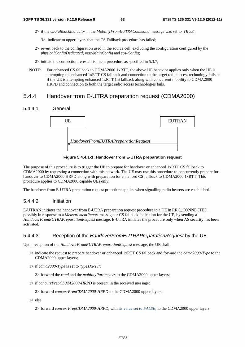
ETSI
ETSI TS 136 331 V9.12.0 (2012-11)633GPP TS 36.331 version 9.12.0 Release 9
2> if the cs-FallbackIndicator in the MobilityFromEUTRACommand message was set to 'TRUE':
3> indicate to upper layers that the CS Fallback procedure has failed;
2> revert back to the configuration used in the source cell, excluding the configuration configured by the physicalConfigDedicated, mac-MainConfig and sps-Config;
2> initiate the connection re-establishment procedure as specified in 5.3.7;
NOTE: For enhanced CS fallback to CDMA2000 1xRTT, the above UE behavior applies only when the UE is attempting the enhanced 1xRTT CS fallback and connection to the target radio access technology fails or if the UE is attempting enhanced 1xRTT CS fallback along with concurrent mobility to CDMA2000 HRPD and connection to both the target radio access technologies fails.
5.4.4 Handover from E-UTRA preparation request (CDMA2000)
5.4.4.1 General
HandoverFromEUTRAPreparationRequest
UE EUTRAN
Figure 5.4.4.1-1: Handover from E-UTRA preparation request
The purpose of this procedure is to trigger the UE to prepare for handover or enhanced 1xRTT CS fallback to CDMA2000 by requesting a connection with this network. The UE may use this procedure to concurrently prepare for handover to CDMA2000 HRPD along with preparation for enhanced CS fallback to CDMA2000 1xRTT. This procedure applies to CDMA2000 capable UEs only.
The handover from E-UTRA preparation request procedure applies when signalling radio bearers are established.
5.4.4.2 Initiation
E-UTRAN initiates the handover from E-UTRA preparation request procedure to a UE in RRC_CONNECTED, possibly in response to a MeasurementReport message or CS fallback indication for the UE, by sending a HandoverFromEUTRAPreparationRequest message. E-UTRA initiates the procedure only when AS security has been activated.
5.4.4.3 Reception of the HandoverFromEUTRAPreparationRequest by the UE
Upon reception of the HandoverFromEUTRAPreparationRequest message, the UE shall:
1> indicate the request to prepare handover or enhanced 1xRTT CS fallback and forward the cdma2000-Type to the CDMA2000 upper layers;
1> if cdma2000-Type is set to 'type1XRTT':
2> forward the rand and the mobilityParameters to the CDMA2000 upper layers;
1> if concurrPrepCDMA2000-HRPD is present in the received message:
2> forward concurrPrepCDMA2000-HRPD to the CDMA2000 upper layers;
1> else
2> forward concurrPrepCDMA2000-HRPD, with its value set to FALSE, to the CDMA2000 upper layers;

ETSI
ETSI TS 136 331 V9.12.0 (2012-11)643GPP TS 36.331 version 9.12.0 Release 9
5.4.5 UL handover preparation transfer (CDMA2000)
5.4.5.1 General
ULHandoverPreparationTransfer
UE EUTRAN
Figure 5.4.5.1-1: UL handover preparation transfer
The purpose of this procedure is to tunnel the handover related CDMA2000 dedicated information or enhanced 1xRTT CS fallback related CDMA2000 dedicated information from UE to E-UTRAN when requested by the higher layers. The procedure is triggered by the higher layers on receipt of HandoverFromEUTRAPreparationRequest message. If preparing for enhanced CS fallback to CDMA2000 1xRTT and handover to CDMA2000 HRPD, the UE sends two consecutive ULHandoverPreparationTransfer messages to E-UTRAN, one per addressed CDMA2000 RAT Type. This procedure applies to CDMA2000 capable UEs only.
5.4.5.2 Initiation
A UE in RRC_CONNECTED initiates the UL Handover Preparation Transfer procedure whenever there is a need to transfer handover or enhanced 1xRTT CS fallback related non-3GPP dedicated information. The UE initiates the UL handover preparation transfer procedure by sending the ULHandoverPreparationTransfer message.
5.4.5.3 Actions related to transmission of the ULHandoverPreparationTransfer message
The UE shall set the contents of the ULHandoverPreparationTransfer message as follows:
1> include the cdma2000-Type and the dedicatedInfo;
1> if the cdma2000-Type is set to 'type1XRTT':
2> include the meid and set it to the value received from the CDMA2000 upper layers;
1> submit the ULHandoverPreparationTransfer message to lower layers for transmission, upon which the procedure ends;
5.4.5.4 Failure to deliver the ULHandoverPreparationTransfer message
The UE shall:
1> if the UE is unable to guarantee successful delivery of ULHandoverPreparationTransfer messages:
2> inform upper layers about the possible failure to deliver the information contained in the concerned ULHandoverPreparationTransfer message;
5.4.6 Inter-RAT cell change order to E-UTRAN
5.4.6.1 General
The purpose of the inter-RAT cell change order to E-UTRAN procedure is to transfer, under the control of the source radio access technology, a connection between the UE and another radio access technology (e.g. GSM/ GPRS) to E-UTRAN.

ETSI
ETSI TS 136 331 V9.12.0 (2012-11)653GPP TS 36.331 version 9.12.0 Release 9
5.4.6.2 Initiation
The procedure is initiated when a radio access technology other than E-UTRAN, e.g. GSM/GPRS, using procedures specific for that RAT, orders the UE to change to an E-UTRAN cell. In response, upper layers request the establishment of an RRC connection as specified in subclause 5.3.3.
NOTE: Within the message used to order the UE to change to an E-UTRAN cell, the source RAT should specify the identity of the target E-UTRAN cell as specified in the specifications for that RAT.
The UE shall:
1> upon receiving an RRCConnectionSetup message:
2> consider the inter-RAT cell change order procedure to have completed succesfully;
5.4.6.3 UE fails to complete an inter-RAT cell change order
If the inter-RAT cell change order fails the UE shall return to the other radio access technology and proceed as specified in the appropriate specifications for that RAT.
The UE shall:
1> upon failure to establish the RRC connection as specified in subclause 5.3.3:
2> consider the inter-RAT cell change order procedure to have failed;
NOTE: The cell change was network ordered. Therefore, failure to change to the target cell should not cause the UE to move to UE-controlled cell selection.
5.5 Measurements
5.5.1 Introduction
The UE reports measurement information in accordance with the measurement configuration as provided by E-UTRAN. E-UTRAN provides the measurement configuration applicable for a UE in RRC_CONNECTED by means of dedicated signalling, i.e. using the RRCConnectionReconfiguration message.
The UE can be requested to perform the following types of measurements:
- Intra-frequency measurements: measurements at the downlink carrier frequency of the serving cell.
- Inter-frequency measurements: measurements at frequencies that differ from the downlink carrier frequency of the serving cell.
- Inter-RAT measurements of UTRA frequencies.
- Inter-RAT measurements of GERAN frequencies.
- Inter-RAT measurements of CDMA2000 HRPD or CDMA2000 1xRTT frequencies.
The measurement configuration includes the following parameters:
1. Measurement objects: The objects on which the UE shall perform the measurements.
- For intra-frequency and inter-frequency measurements a measurement object is a single E-UTRA carrier frequency. Associated with this carrier frequency, E-UTRAN can configure a list of cell specific offsets and a list of 'blacklisted' cells. Blacklisted cells are not considered in event evaluation or measurement reporting.
- For inter-RAT UTRA measurements a measurement object is a set of cells on a single UTRA carrier frequency.
- For inter-RAT GERAN measurements a measurement object is a set of GERAN carrier frequencies.

ETSI
ETSI TS 136 331 V9.12.0 (2012-11)663GPP TS 36.331 version 9.12.0 Release 9
- For inter-RAT CDMA2000 measurements a measurement object is a set of cells on a single (HRPD or 1xRTT) carrier frequency.
NOTE 1: Some measurements using the above mentioned measurement objects, only concern a single cell, e.g. measurements used to report neighbouring cell system information, serving cell UE Rx- Tx time difference.
2. Reporting configurations: A list of reporting configurations where each reporting configuration consists of the following:
- Reporting criterion: The criterion that triggers the UE to send a measurement report. This can either be periodical or a single event description.
- Reporting format: The quantities that the UE includes in the measurement report and associated information (e.g. number of cells to report).
3. Measurement identities: A list of measurement identities where each measurement identity links one measurement object with one reporting configuration. By configuring multiple measurement identities it is possible to link more than one measurement object to the same reporting configuration, as well as to link more than one reporting configuration to the same measurement object. The measurement identity is used as a reference number in the measurement report.
4. Quantity configurations: One quantity configuration is configured per RAT type. The quantity configuration defines the measurement quantities and associated filtering used for all event evaluation and related reporting of that measurement type. One filter can be configured per measurement quantity.
5. Measurement gaps: Periods that the UE may use to perform measurements, i.e. no (UL, DL) transmissions are scheduled.
E-UTRAN only configures a single measurement object for a given frequency, i.e. it is not possible to configure two or more measurement objects for the same frequency with different associated parameters, e.g. different offsets and/ or blacklists. E-UTRAN may configure multiple instances of the same event e.g. by configuring two reporting configurations with different thresholds.
The UE maintains a single measurement object list, a single reporting configuration list, and a single measurement identities list. The measurement object list includes measurement objects, that are specified per RAT type, possibly including an intra-frequency object (i.e. the object corresponding to the serving frequency), inter-frequency object(s) and inter-RAT objects. Similarly, the reporting configuration list includes E-UTRA and inter-RAT reporting configurations. Any measurement object can be linked to any reporting configuration of the same RAT type. Some reporting configurations may not be linked to a measurement object. Likewise, some measurement objects may not be linked to a reporting configuration.
The measurement procedures distinguish the following types of cells:
1. The serving cell.
2. Listed cells - these are cells listed within the measurement object(s).
3. Detected cells - these are cells that are not listed within the measurement object(s) but are detected by the UE on the carrier frequency(ies) indicated by the measurement object(s).
For E-UTRA, the UE measures and reports on the serving cell, listed cells and detected cells. For inter-RAT UTRA, the UE measures and reports on listed cells and optionally on cells that are within a range for which reporting is allowed by E-UTRAN. For inter-RAT GERAN, the UE measures and reports on detected cells. For inter-RAT CDMA2000, the UE measures and reports on listed cells.
NOTE 2: For inter-RAT UTRA and CDMA2000, the UE measures and reports also on detected cells for the purpose of SON.
NOTE 3: This specification is based on the assumption that typically CSG cells of home deployment type are not indicated within the neighbour list. Furthermore, the assumption is that for non-home deployments, the physical cell identity is unique within the area of a large macro cell (i.e. as for UTRAN).

ETSI
ETSI TS 136 331 V9.12.0 (2012-11)673GPP TS 36.331 version 9.12.0 Release 9
Whenever the procedural specification, other than contained in sub-clause 5.5.2, refers to a field it concerns a field included in the VarMeasConfig unless explictly stated otherwise i.e. only the measurement configuration procedure covers the direct UE action related to the received measConfig.
5.5.2 Measurement configuration
5.5.2.1 General
E-UTRAN applies the procedure as follows:
- to ensure that, whenever the UE has a measConfig, it includes a measObject for the serving frequency;
- to configure at most one measurement identity using a reporting configuration with the purpose set to 'reportCGI';
The UE shall:
1> if the received measConfig includes the measObjectToRemoveList:
2> perform the measurement object removal procedure as specified in 5.5.2.4;
1> if the received measConfig includes the measObjectToAddModList:
2> perform the measurement object addition/ modification procedure as specified in 5.5.2.5;
1> if the received measConfig includes the reportConfigToRemoveList:
2> perform the reporting configuration removal procedure as specified in 5.5.2.6;
1> if the received measConfig includes the reportConfigToAddModList:
2> perform the reporting configuration addition/ modification procedure as specified in 5.5.2.7;
1> if the received measConfig includes the quantityConfig:
2> perform the quantity configuration procedure as specified in 5.5.2.8;
1> if the received measConfig includes the measIdToRemoveList:
2> perform the measurement identity removal procedure as specified in 5.5.2.2;
1> if the received measConfig includes the measIdToAddModList:
2> perform the measurement identity addition/ modification procedure as specified in 5.5.2.3;
1> if the received measConfig includes the measGapConfig:
2> perform the measurement gap configuration procedure as specified in 5.5.2.9;
1> if the received measConfig includes the s-Measure:
2> set the parameter s-Measure within VarMeasConfig to the lowest value of the RSRP ranges indicated by the received value of s-Measure;
1> if the received measConfig includes the preRegistrationInfoHRPD:
2> forward the preRegistrationInfoHRPD to CDMA2000 upper layers;
1> if the received measConfig includes the speedStatePars:
2> set the parameter speedStatePars within VarMeasConfig to the received value of speedStatePars;
5.5.2.2 Measurement identity removal
The UE shall:
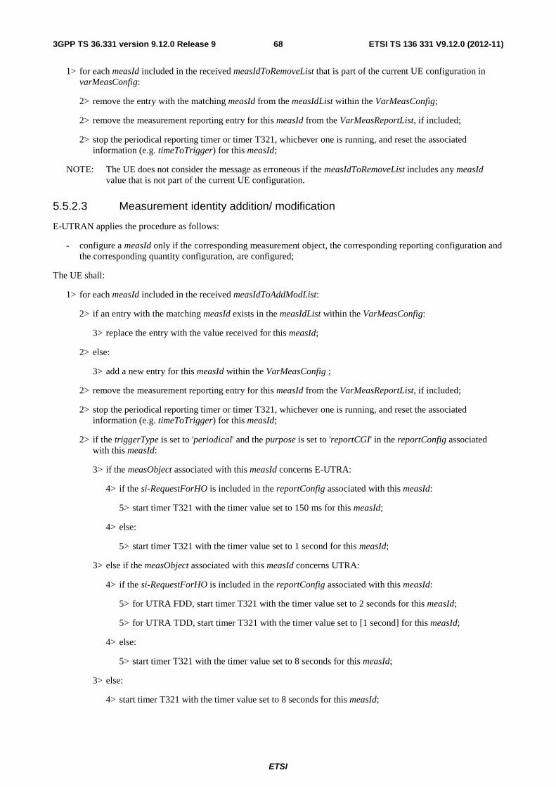
ETSI
ETSI TS 136 331 V9.12.0 (2012-11)683GPP TS 36.331 version 9.12.0 Release 9
1> for each measId included in the received measIdToRemoveList that is part of the current UE configuration in varMeasConfig:
2> remove the entry with the matching measId from the measIdList within the VarMeasConfig;
2> remove the measurement reporting entry for this measId from the VarMeasReportList, if included;
2> stop the periodical reporting timer or timer T321, whichever one is running, and reset the associated information (e.g. timeToTrigger) for this measId;
NOTE: The UE does not consider the message as erroneous if the measIdToRemoveList includes any measId value that is not part of the current UE configuration.
5.5.2.3 Measurement identity addition/ modification
E-UTRAN applies the procedure as follows:
- configure a measId only if the corresponding measurement object, the corresponding reporting configuration and the corresponding quantity configuration, are configured;
The UE shall:
1> for each measId included in the received measIdToAddModList:
2> if an entry with the matching measId exists in the measIdList within the VarMeasConfig:
3> replace the entry with the value received for this measId;
2> else:
3> add a new entry for this measId within the VarMeasConfig ;
2> remove the measurement reporting entry for this measId from the VarMeasReportList, if included;
2> stop the periodical reporting timer or timer T321, whichever one is running, and reset the associated information (e.g. timeToTrigger) for this measId;
2> if the triggerType is set to 'periodical' and the purpose is set to 'reportCGI' in the reportConfig associated with this measId:
3> if the measObject associated with this measId concerns E-UTRA:
4> if the si-RequestForHO is included in the reportConfig associated with this measId:
5> start timer T321 with the timer value set to 150 ms for this measId;
4> else:
5> start timer T321 with the timer value set to 1 second for this measId;
3> else if the measObject associated with this measId concerns UTRA:
4> if the si-RequestForHO is included in the reportConfig associated with this measId:
5> for UTRA FDD, start timer T321 with the timer value set to 2 seconds for this measId;
5> for UTRA TDD, start timer T321 with the timer value set to [1 second] for this measId;
4> else:
5> start timer T321 with the timer value set to 8 seconds for this measId;
3> else:
4> start timer T321 with the timer value set to 8 seconds for this measId;

ETSI
ETSI TS 136 331 V9.12.0 (2012-11)693GPP TS 36.331 version 9.12.0 Release 9
5.5.2.4 Measurement object removal
The UE shall:
1> for each measObjectId included in the received measObjectToRemoveList that is part of the current UE configuration in varMeasConfig:
2> remove the entry with the matching measObjectId from the measObjectList within the VarMeasConfig;
2> remove all measId associated with this measObjectId from the measIdList within the VarMeasConfig, if any;
2> if a measId is removed from the measIdList:
3> remove the measurement reporting entry for this measId from the VarMeasReportList, if included;
3> stop the periodical reporting timer or timer T321, whichever one is running, and reset the associated information (e.g. timeToTrigger) for this measId;
NOTE: The UE does not consider the message as erroneous if the measObjectToRemoveList includes any measObjectId value that is not part of the current UE configuration.
5.5.2.5 Measurement object addition/ modification
The UE shall:
1> for each measObjectId included in the received measObjectToAddModList:
2> if an entry with the matching measObjectId exists in the measObjectList within the VarMeasConfig, for this entry:
3> replace the entry with the value received for this measObject, except for the fields cellsToAddModList, blackCellsToAddModList, cellsToRemoveList and blackCellsToRemoveList:
3> if the received measObject includes the cellsToRemoveList:
4> for each cellIndex included in the cellsToRemoveList:
5> remove the entry with the matching cellIndex from the cellsToAddModList;
3> if the received measObject includes the cellsToAddModList:
4> for each cellIndex value included in the cellsToAddModList:
5> if an entry with the matching cellIndex exists in the cellsToAddModList:
6> replace the entry with the value received for this cellIndex;
5> else:
6> add a new entry for the received cellIndex to the cellsToAddModList;
3> if the received measObject includes the blackCellsToRemoveList:
4> for each cellIndex included in the blackCellsToRemoveList:
5> remove the entry with the matching cellIndex from the blackCellsToAddModList;
3> if the received measObject includes the blackCellsToAddModList:
4> for each cellIndex included in the blackCellsToAddModList:
5> if an entry with the matching cellIndex is included in the blackCellsToAddModList:
6> replace the entry with the value received for this cellIndex;
5> else:
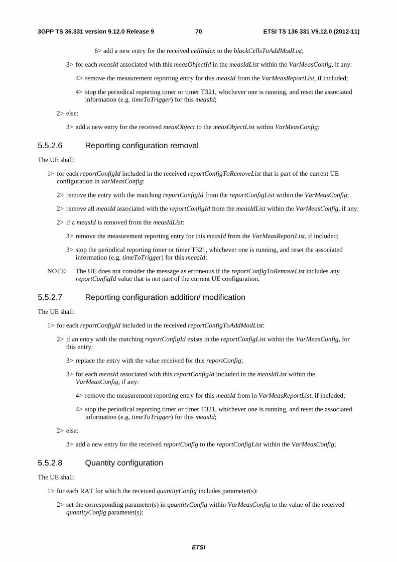
ETSI
ETSI TS 136 331 V9.12.0 (2012-11)703GPP TS 36.331 version 9.12.0 Release 9
6> add a new entry for the received cellIndex to the blackCellsToAddModList;
3> for each measId associated with this measObjectId in the measIdList within the VarMeasConfig, if any:
4> remove the measurement reporting entry for this measId from the VarMeasReportList, if included;
4> stop the periodical reporting timer or timer T321, whichever one is running, and reset the associated information (e.g. timeToTrigger) for this measId;
2> else:
3> add a new entry for the received measObject to the measObjectList within VarMeasConfig;
5.5.2.6 Reporting configuration removal
The UE shall:
1> for each reportConfigId included in the received reportConfigToRemoveList that is part of the current UE configuration in varMeasConfig:
2> remove the entry with the matching reportConfigId from the reportConfigList within the VarMeasConfig;
2> remove all measId associated with the reportConfigId from the measIdList within the VarMeasConfig, if any;
2> if a measId is removed from the measIdList:
3> remove the measurement reporting entry for this measId from the VarMeasReportList, if included;
3> stop the periodical reporting timer or timer T321, whichever one is running, and reset the associated information (e.g. timeToTrigger) for this measId;
NOTE: The UE does not consider the message as erroneous if the reportConfigToRemoveList includes any reportConfigId value that is not part of the current UE configuration.
5.5.2.7 Reporting configuration addition/ modification
The UE shall:
1> for each reportConfigId included in the received reportConfigToAddModList:
2> if an entry with the matching reportConfigId exists in the reportConfigList within the VarMeasConfig, for this entry:
3> replace the entry with the value received for this reportConfig;
3> for each measId associated with this reportConfigId included in the measIdList within the VarMeasConfig, if any:
4> remove the measurement reporting entry for this measId from in VarMeasReportList, if included;
4> stop the periodical reporting timer or timer T321, whichever one is running, and reset the associated information (e.g. timeToTrigger) for this measId;
2> else:
3> add a new entry for the received reportConfig to the reportConfigList within the VarMeasConfig;
5.5.2.8 Quantity configuration
The UE shall:
1> for each RAT for which the received quantityConfig includes parameter(s):
2> set the corresponding parameter(s) in quantityConfig within VarMeasConfig to the value of the received quantityConfig parameter(s);

ETSI
ETSI TS 136 331 V9.12.0 (2012-11)713GPP TS 36.331 version 9.12.0 Release 9
1> for each measId included in the measIdList within VarMeasConfig:
2> remove the measurement reporting entry for this measId from the VarMeasReportList, if included;
2> stop the periodical reporting timer or timer T321, whichever one is running, and reset the associated information (e.g. timeToTrigger) for this measId;
5.5.2.9 Measurement gap configuration
The UE shall:
1> if measGapConfig is set to 'setup':
2> if a measurement gap configuration is already setup, release the measurement gap configuration;
2> setup the measurement gap configuration indicated by the measGapConfig in accordance with the received gapOffset, i.e., each gap starts at an SFN and subframe meeting the following condition:
SFN mod T = FLOOR(gapOffset/10);
subframe = gapOffset mod 10;
with T = MGRP/10 as defined in TS 36.133 [16];
1> else:
2> release the measurement gap configuration;
5.5.3 Performing measurements
5.5.3.1 General
For all measurements the UE applies the layer 3 filtering as specified in 5.5.3.2, before using the measured results for evaluation of reporting criteria or for measurement reporting.
The UE shall:
1> for each measId included in the measIdList within VarMeasConfig:
2> if the purpose for the associated reportConfig is set to 'reportCGI':
3> if si-RequestForHO is configured for the associated reportConfig:
4> perform the corresponding measurements on the frequency and RAT indicated in the associated measObject using autonomous gaps as necessary;
3> else:
4> perform the corresponding measurements on the frequency and RAT indicated in the associated measObject using available idle periods or using autonomous gaps as necessary;
NOTE 1: If autonomous gaps are used to perform measurements, the UE is allowed to temporarily abort communication with the serving cell, i.e. create autonomous gaps to perform the corresponding measurements within the limits specified in TS 36.133 [16]. Otherwise, the UE only supports the measurements with the purpose set to 'reportCGI' only if E-UTRAN has provided sufficient idle periods.
3> try to acquire the global cell identity of the cell indicated by the cellForWhichToReportCGI in the associated measObject by acquiring the relevant system information from the concerned cell;
3> if the cell indicated by the cellForWhichToReportCGI included in the associated measObject is an E-UTRAN cell:
4> try to acquire the CSG identity, if the CSG identity is broadcast in the concerned cell;

ETSI
ETSI TS 136 331 V9.12.0 (2012-11)723GPP TS 36.331 version 9.12.0 Release 9
4> try to acquire the list of additional PLMN Identities, as included in the plmn-IdentityList, if multiple PLMN identities are broadcast in the concerned cell;
NOTE 2: The 'primary' PLMN is part of the global cell identity.
3> if the cell indicated by the cellForWhichToReportCGI included in the associated measObject is a UTRAN cell:
4> try to acquire the LAC, the RAC and the list of additional PLMN Identities, if multiple PLMN identities are broadcast in the concerned cell;
4> try to acquire the CSG identity, if the CSG identity is broadcast in the concerned cell;
3> if the cell indicated by the cellForWhichToReportCGI included in the associated measObject is a GERAN cell:
4> try to acquire the RAC in the concerned cell;
3> if the cell indicated by the cellForWhichToReportCGI included in the associated measObject is a CDMA2000 cell and the cdma2000-Type included in the measObject is 'typeHRPD':
4> try to acquire the Sector ID in the concerned cell;
3> if the cell indicated by the cellForWhichToReportCGI included in the associated measObject is a CDMA2000 cell and the cdma2000-Type included in the measObject is 'type1XRTT':
4> try to acquire the BASE ID, SID and NID in the concerned cell;
2> else:
3> if a measurement gap configuration is setup; or
3> if the UE does not require measurement gaps to perform the concerned measurements:
4> if s-Measure is not configured; or
4> if s-Measure is configured and the serving cell RSRP, after layer 3 filtering, is lower than this value:
5> perform the corresponding measurements of neighbouring cells on the frequencies and RATs indicated in the concerned measObject;
4> if the ue-RxTxTimeDiffPeriodical is configured in the associated reportConfig:
5> perform the UE Rx – Tx time difference measurements on the serving cell;
2> perform the evaluation of reporting criteria as specified in 5.5.4;
NOTE 3: The 's-Measure' defines when the UE is required to perform measurements. The UE is however allowed to perform measurements also when the serving cell RSRP exceeds 's-Measure', e.g., to measure cells broadcasting a CSG identity following use of the autonomous search function as defined in TS 36.304 [4].
5.5.3.2 Layer 3 filtering
The UE shall:
1> for each measurement quantity that the UE performs measurements according to 5.5.3.1:
NOTE 1: This does not include quantities configured solely for UE Rx- Tx time difference measurements i.e. for those type of measurements the UE ignores the triggerQuantity and reportQuantity.
2> filter the measured result, before using for evaluation of reporting criteria or for measurement reporting, by the following formula:
nnn MaFaF ⋅+⋅−= −1)1(

ETSI
ETSI TS 136 331 V9.12.0 (2012-11)733GPP TS 36.331 version 9.12.0 Release 9
where
Mn is the latest received measurement result from the physical layer;
Fn is the updated filtered measurement result, that is used for evaluation of reporting criteria or for measurement reporting;
Fn-1 is the old filtered measurement result, where F0 is set to M1 when the first measurement result from the physical layer is received; and
a = 1/2(k/4), where k is the filterCoefficent for the corresponding measurement quantity received by the quantityConfig;
2> adapt the filter such that the time characteristics of the filter are preserved at different input rates, observing that the filterCoefficent k assumes a sample rate equal to 200 ms;
NOTE 2: If k is set to 0, no layer 3 filtering is applicable.
NOTE 3: The filtering is performed in the same domain as used for evaluation of reporting criteria or for measurement reporting, i.e., logarithmic filtering for logarithmic measurements.
NOTE 4: The filter input rate is implementation dependent, to fulfil the performance requirements set in [16]. For further details about the physical layer measurements, see TS 36.133 [16].
5.5.4 Measurement report triggering
5.5.4.1 General
The UE shall:
1> for each measId included in the measIdList within VarMeasConfig:
2> if the corresponding reportConfig includes a purpose set to 'reportStrongestCellsForSON':
3> consider any neighbouring cell detected on the associated frequency to be applicable;
2> else if the corresponding reportConfig includes a purpose set to 'reportCGI':
3> consider any neighbouring cell detected on the associated frequency/ set of frequencies (GERAN) which has a physical cell identity matching the value of the cellForWhichToReportCGI included in the corresponding measObject within the VarMeasConfig to be applicable;
2> else:
3> if the corresponding measObject concerns E-UTRA:
4> if the ue-RxTxTimeDiffPeriodical, eventA1 or eventA2 is configured in the corresponding reportConfig:
5> consider only the serving cell to be applicable;
4> else:
5> consider any neighbouring cell detected on the associated frequency to be applicable when the concerned cell is not included in the blackCellsToAddModList defined within the VarMeasConfig for this measId;
3> else if the corresponding measObject concerns UTRA or CDMA2000:
4> consider a neighbouring cell on the associated frequency to be applicable when the concerned cell is included in the cellsToAddModList defined within the VarMeasConfig for this measId (i.e. the cell is included in the white-list);

ETSI
ETSI TS 136 331 V9.12.0 (2012-11)743GPP TS 36.331 version 9.12.0 Release 9
NOTE 0: The UE may also consider a neighbouring cell on the associated UTRA frequency to be applicable when the concerned cell is included in the csg-allowedReportingCells within the VarMeasConfig for this measId, if configured in the corresponding measObjectUTRA (i.e. the cell is included in the range of physical cell identities for which reporting is allowed).
3> else if the corresponding measObject concerns GERAN:
4> consider a neighbouring cell on the associated set of frequencies to be applicable when the concerned cell matches the ncc-Permitted defined within the VarMeasConfig for this measId;
2> if the triggerType is set to 'event' and if the entry condition applicable for this event, i.e. the event corresponding with the eventId of the corresponding reportConfig within VarMeasConfig, is fulfilled for one or more applicable cells for all measurements after layer 3 filtering taken during timeToTrigger defined for this event within the VarMeasConfig, while the VarMeasReportList does not include an measurement reporting entry for this measId (a first cell triggers the event):
3> include a measurement reporting entry within the VarMeasReportList for this measId;
3> set the numberOfReportsSent defined within the VarMeasReportList for this measId to 0;
3> include the concerned cell(s) in the cellsTriggeredList defined within the VarMeasReportList for this measId;
3> initiate the measurement reporting procedure, as specified in 5.5.5;
2> if the triggerType is set to 'event' and if the entry condition applicable for this event, i.e. the event corresponding with the eventId of the corresponding reportConfig within VarMeasConfig, is fulfilled for one or more applicable cells not included in the cellsTriggeredList for all measurements after layer 3 filtering taken during timeToTrigger defined for this event within the VarMeasConfig (a subsequent cell triggers the event):
3> set the numberOfReportsSent defined within the VarMeasReportList for this measId to 0;
3> include the concerned cell(s) in the cellsTriggeredList defined within the VarMeasReportList for this measId;
3> initiate the measurement reporting procedure, as specified in 5.5.5;
2> if the triggerType is set to 'event' and if the leaving condition applicable for this event is fulfilled for one or more of the cells included in the cellsTriggeredList defined within the VarMeasReportList for this measId for all measurements after layer 3 filtering taken during timeToTrigger defined within the VarMeasConfig for this event:
3> remove the concerned cell(s) in the cellsTriggeredList defined within the VarMeasReportList for this measId;
3> if reportOnLeave is set to TRUE for the corresponding reporting configuration:
4> initiate the measurement reporting procedure, as specified in 5.5.5;
3> if the cellsTriggeredList defined within the VarMeasReportList for this measId is empty:
4> remove the measurement reporting entry within the VarMeasReportList for this measId;
4> stop the periodical reporting timer for this measId, if running;
2> if the purpose is included and set to 'reportStrongestCells' or to 'reportStrongestCellsForSON' and if a (first) measurement result is available for one or more applicable cells:
3> include a measurement reporting entry within the VarMeasReportList for this measId;
3> set the numberOfReportsSent defined within the VarMeasReportList for this measId to 0;
3> initiate the measurement reporting procedure, as specified in 5.5.5;
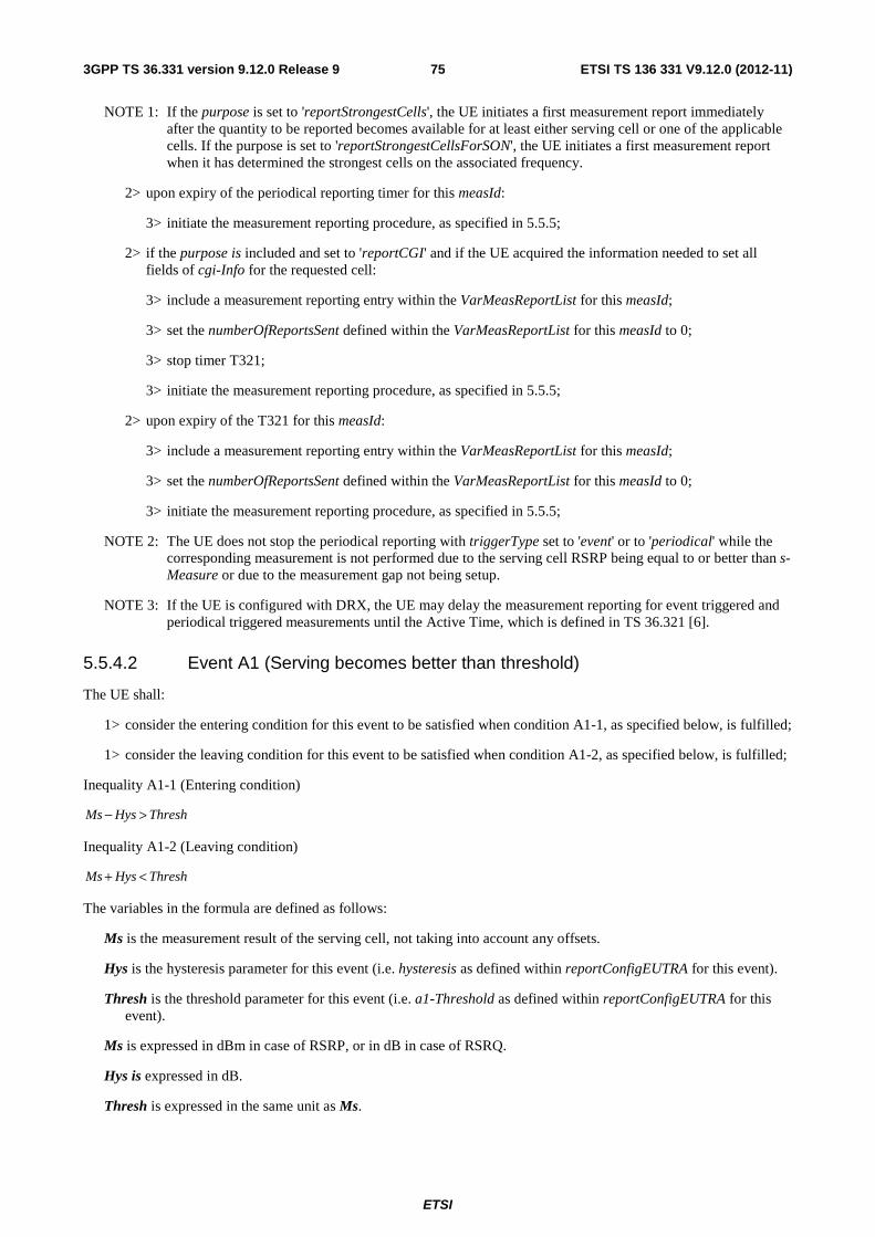
ETSI
ETSI TS 136 331 V9.12.0 (2012-11)753GPP TS 36.331 version 9.12.0 Release 9
NOTE 1: If the purpose is set to 'reportStrongestCells', the UE initiates a first measurement report immediately after the quantity to be reported becomes available for at least either serving cell or one of the applicable cells. If the purpose is set to 'reportStrongestCellsForSON', the UE initiates a first measurement report when it has determined the strongest cells on the associated frequency.
2> upon expiry of the periodical reporting timer for this measId:
3> initiate the measurement reporting procedure, as specified in 5.5.5;
2> if the purpose is included and set to 'reportCGI' and if the UE acquired the information needed to set all fields of cgi-Info for the requested cell:
3> include a measurement reporting entry within the VarMeasReportList for this measId;
3> set the numberOfReportsSent defined within the VarMeasReportList for this measId to 0;
3> stop timer T321;
3> initiate the measurement reporting procedure, as specified in 5.5.5;
2> upon expiry of the T321 for this measId:
3> include a measurement reporting entry within the VarMeasReportList for this measId;
3> set the numberOfReportsSent defined within the VarMeasReportList for this measId to 0;
3> initiate the measurement reporting procedure, as specified in 5.5.5;
NOTE 2: The UE does not stop the periodical reporting with triggerType set to 'event' or to 'periodical' while the corresponding measurement is not performed due to the serving cell RSRP being equal to or better than s-Measure or due to the measurement gap not being setup.
NOTE 3: If the UE is configured with DRX, the UE may delay the measurement reporting for event triggered and periodical triggered measurements until the Active Time, which is defined in TS 36.321 [6].
5.5.4.2 Event A1 (Serving becomes better than threshold)
The UE shall:
1> consider the entering condition for this event to be satisfied when condition A1-1, as specified below, is fulfilled;
1> consider the leaving condition for this event to be satisfied when condition A1-2, as specified below, is fulfilled;
Inequality A1-1 (Entering condition)
ThreshHysMs >−
Inequality A1-2 (Leaving condition)
ThreshHysMs <+
The variables in the formula are defined as follows:
Ms is the measurement result of the serving cell, not taking into account any offsets.
Hys is the hysteresis parameter for this event (i.e. hysteresis as defined within reportConfigEUTRA for this event).
Thresh is the threshold parameter for this event (i.e. a1-Threshold as defined within reportConfigEUTRA for this event).
Ms is expressed in dBm in case of RSRP, or in dB in case of RSRQ.
Hys is expressed in dB.
Thresh is expressed in the same unit as Ms.
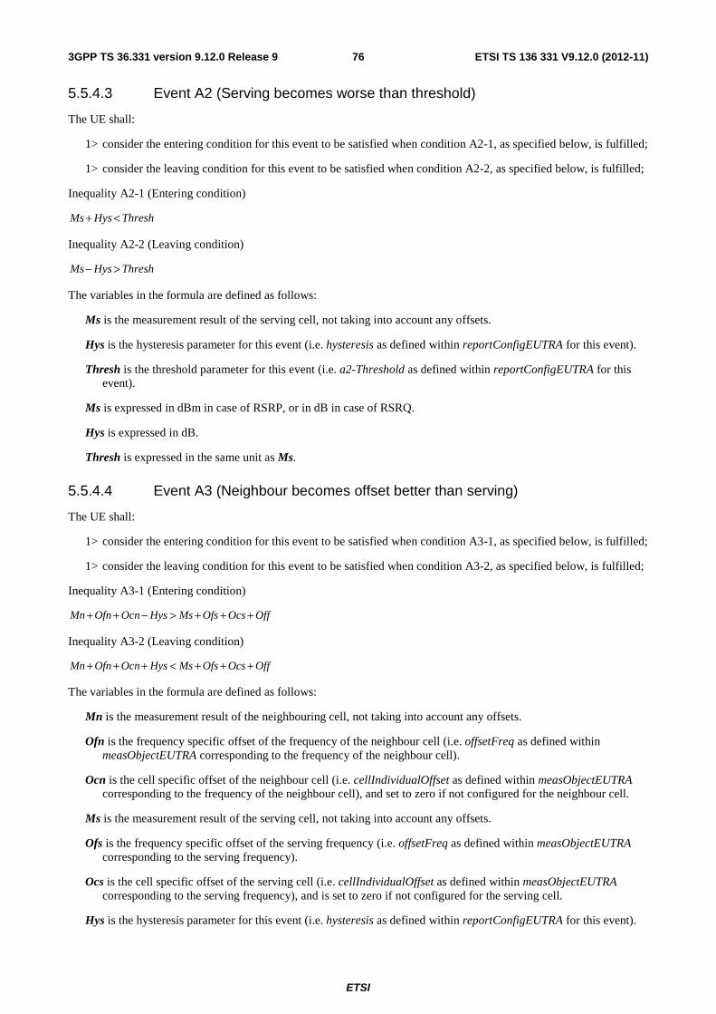
ETSI
ETSI TS 136 331 V9.12.0 (2012-11)763GPP TS 36.331 version 9.12.0 Release 9
5.5.4.3 Event A2 (Serving becomes worse than threshold)
The UE shall:
1> consider the entering condition for this event to be satisfied when condition A2-1, as specified below, is fulfilled;
1> consider the leaving condition for this event to be satisfied when condition A2-2, as specified below, is fulfilled;
Inequality A2-1 (Entering condition)
ThreshHysMs <+
Inequality A2-2 (Leaving condition)
ThreshHysMs >−
The variables in the formula are defined as follows:
Ms is the measurement result of the serving cell, not taking into account any offsets.
Hys is the hysteresis parameter for this event (i.e. hysteresis as defined within reportConfigEUTRA for this event).
Thresh is the threshold parameter for this event (i.e. a2-Threshold as defined within reportConfigEUTRA for this event).
Ms is expressed in dBm in case of RSRP, or in dB in case of RSRQ.
Hys is expressed in dB.
Thresh is expressed in the same unit as Ms.
5.5.4.4 Event A3 (Neighbour becomes offset better than serving)
The UE shall:
1> consider the entering condition for this event to be satisfied when condition A3-1, as specified below, is fulfilled;
1> consider the leaving condition for this event to be satisfied when condition A3-2, as specified below, is fulfilled;
Inequality A3-1 (Entering condition)
OffOcsOfsMsHysOcnOfnMn +++>−++
Inequality A3-2 (Leaving condition)
OffOcsOfsMsHysOcnOfnMn +++<+++
The variables in the formula are defined as follows:
Mn is the measurement result of the neighbouring cell, not taking into account any offsets.
Ofn is the frequency specific offset of the frequency of the neighbour cell (i.e. offsetFreq as defined within measObjectEUTRA corresponding to the frequency of the neighbour cell).
Ocn is the cell specific offset of the neighbour cell (i.e. cellIndividualOffset as defined within measObjectEUTRA corresponding to the frequency of the neighbour cell), and set to zero if not configured for the neighbour cell.
Ms is the measurement result of the serving cell, not taking into account any offsets.
Ofs is the frequency specific offset of the serving frequency (i.e. offsetFreq as defined within measObjectEUTRA corresponding to the serving frequency).
Ocs is the cell specific offset of the serving cell (i.e. cellIndividualOffset as defined within measObjectEUTRA corresponding to the serving frequency), and is set to zero if not configured for the serving cell.
Hys is the hysteresis parameter for this event (i.e. hysteresis as defined within reportConfigEUTRA for this event).

ETSI
ETSI TS 136 331 V9.12.0 (2012-11)773GPP TS 36.331 version 9.12.0 Release 9
Off is the offset parameter for this event (i.e. a3-Offset as defined within reportConfigEUTRA for this event).
Mn, Ms are expressed in dBm in case of RSRP, or in dB in case of RSRQ.
Ofn, Ocn, Ofs, Ocs, Hys, Off are expressed in dB.
5.5.4.5 Event A4 (Neighbour becomes better than threshold)
The UE shall:
1> consider the entering condition for this event to be satisfied when condition A4-1, as specified below, is fulfilled;
1> consider the leaving condition for this event to be satisfied when condition A4-2, as specified below, is fulfilled;
Inequality A4-1 (Entering condition)
ThreshHysOcnOfnMn >−++
Inequality A4-2 (Leaving condition)
ThreshHysOcnOfnMn <+++
The variables in the formula are defined as follows:
Mn is the measurement result of the neighbouring cell, not taking into account any offsets.
Ofn is the frequency specific offset of the frequency of the neighbour cell (i.e. offsetFreq as defined within measObjectEUTRA corresponding to the frequency of the neighbour cell).
Ocn is the cell specific offset of the neighbour cell (i.e. cellIndividualOffset as defined within measObjectEUTRA corresponding to the frequency of the neighbour cell), and set to zero if not configured for the neighbour cell.
Hys is the hysteresis parameter for this event (i.e. hysteresis as defined within reportConfigEUTRA for this event).
Thresh is the threshold parameter for this event (i.e. a4-Threshold as defined within reportConfigEUTRA for this event).
Mn is expressed in dBm in case of RSRP, or in dB in case of RSRQ.
Ofn, Ocn, Hys are expressed in dB.
Thresh is expressed in the same unit as Ms.
5.5.4.6 Event A5 (Serving becomes worse than threshold1 and neighbour becomes better than threshold2)
The UE shall:
1> consider the entering condition for this event to be satisfied when both conditions A5-1 and condition A5-2, as specified below, are fulfilled;
1> consider the leaving condition for this event to be satisfied when condition A5-3 or condition A5-4, i.e. at least one of the two, as specified below, is fulfilled;
Inequality A5-1 (Entering condition 1)
1ThreshHysMs <+
Inequality A5-2 (Entering condition 2)
2ThreshHysOcnOfnMn >−++
Inequality A5-3 (Leaving condition 1)
1ThreshHysMs >−

ETSI
ETSI TS 136 331 V9.12.0 (2012-11)783GPP TS 36.331 version 9.12.0 Release 9
Inequality A5-4 (Leaving condition 2)
2ThreshHysOcnOfnMn <+++
The variables in the formula are defined as follows:
Ms is the measurement result of the serving cell, not taking into account any offsets.
Mn is the measurement result of the neighbouring cell, not taking into account any offsets.
Ofn is the frequency specific offset of the frequency of the neighbour cell (i.e. offsetFreq as defined within measObjectEUTRA corresponding to the frequency of the neighbour cell).
Ocn is the cell specific offset of the neighbour cell (i.e. cellIndividualOffset as defined within measObjectEUTRA corresponding to the frequency of the neighbour cell), and set to zero if not configured for the neighbour cell.
Hys is the hysteresis parameter for this event (i.e. hysteresis as defined within reportConfigEUTRA for this event).
Thresh1 is the threshold parameter for this event (i.e. a5-Threshold1 as defined within reportConfigEUTRA for this event).
Thresh2 is the threshold parameter for this event (i.e. a5-Threshold2 as defined within reportConfigEUTRA for this event).
Mn, Ms are expressed in dBm in case of RSRP, or in dB in case of RSRQ.
Ofn, Ocn, Hys are expressed in dB.
Thresh1 is expressed in the same unit as Ms.
Thresh2 is expressed in the same unit as Mn.
5.5.4.7 Event B1 (Inter RAT neighbour becomes better than threshold)
The UE shall:
1> for UTRA and CDMA2000, only trigger the event for cells included in the corresponding measurement object;
1> consider the entering condition for this event to be satisfied when condition B1-1, as specified below, is fulfilled;
1> consider the leaving condition for this event to be satisfied when condition B1-2, as specified below, is fulfilled;
Inequality B1-1 (Entering condition)
ThreshHysOfnMn >−+
Inequality B1-2 (Leaving condition)
ThreshHysOfnMn <++
The variables in the formula are defined as follows:
Mn is the measurement result of the inter-RAT neighbour cell, not taking into account any offsets. For CDMA 2000 measurement result, pilotStrength is divided by -2.
Ofn is the frequency specific offset of the frequency of the inter-RAT neighbour cell (i.e. offsetFreq as defined within the measObject corresponding to the frequency of the neighbour inter-RAT cell).
Hys is the hysteresis parameter for this event (i.e. hysteresis as defined within reportConfigInterRAT for this event).
Thresh is the threshold parameter for this event (i.e. b1-Threshold as defined within reportConfigInterRAT for this event). For CDMA2000, b1-Threshold is divided by -2.
Mn is expressed in dBm or in dB, depending on the measurement quantity of the inter-RAT neighbour cell.
Ofn, Hys are expressed in dB.

ETSI
ETSI TS 136 331 V9.12.0 (2012-11)793GPP TS 36.331 version 9.12.0 Release 9
Thresh is expressed in the same unit as Mn.
5.5.4.8 Event B2 (Serving becomes worse than threshold1 and inter RAT neighbour becomes better than threshold2)
The UE shall:
1> for UTRA and CDMA2000, only trigger the event for cells included in the corresponding measurement object;
1> consider the entering condition for this event to be satisfied when both condition B2-1 and condition B2-2, as specified below, are fulfilled;
1> consider the leaving condition for this event to be satisfied when condition B2-3 or condition B2-4, i.e. at least one of the two, as specified below, is fulfilled;
Inequality B2-1 (Entering condition 1)
1ThreshHysMs <+
Inequality B2-2 (Entering condition 2)
2ThreshHysOfnMn >−+
Inequality B2-3 (Leaving condition 1)
1ThreshHysMs >−
Inequality B2-4 (Leaving condition 2)
2ThreshHysOfnMn <++
The variables in the formula are defined as follows:
Ms is the measurement result of the serving cell, not taking into account any offsets.
Mn is the measurement result of the inter-RAT neighbour cell, not taking into account any offsets. For CDMA2000 measurement result, pilotStrength is divided by -2.
Ofn is the frequency specific offset of the frequency of the inter-RAT neighbour cell (i.e. offsetFreq as defined within the measObject corresponding to the frequency of the inter-RAT neighbour cell).
Hys is the hysteresis parameter for this event (i.e. hysteresis as defined within reportConfigInterRAT for this event).
Thresh1 is the threshold parameter for this event (i.e. b2-Threshold1 as defined within reportConfigInterRAT for this event).
Thresh2 is the threshold parameter for this event (i.e. b2-Threshold2 as defined within reportConfigInterRAT for this event). For CDMA2000, b2-Threshold2 is divided by -2.
Ms is expressed in dBm in case of RSRP, or in dB in case of RSRQ.
Mn is expressed in dBm or dB, depending on the measurement quantity of the inter-RAT neighbour cell.
Ofn, Hys are expressed in dB.
Thresh1 is expressed in the same unit as Ms.
Thresh2 is expressed in the same unit as Mn.
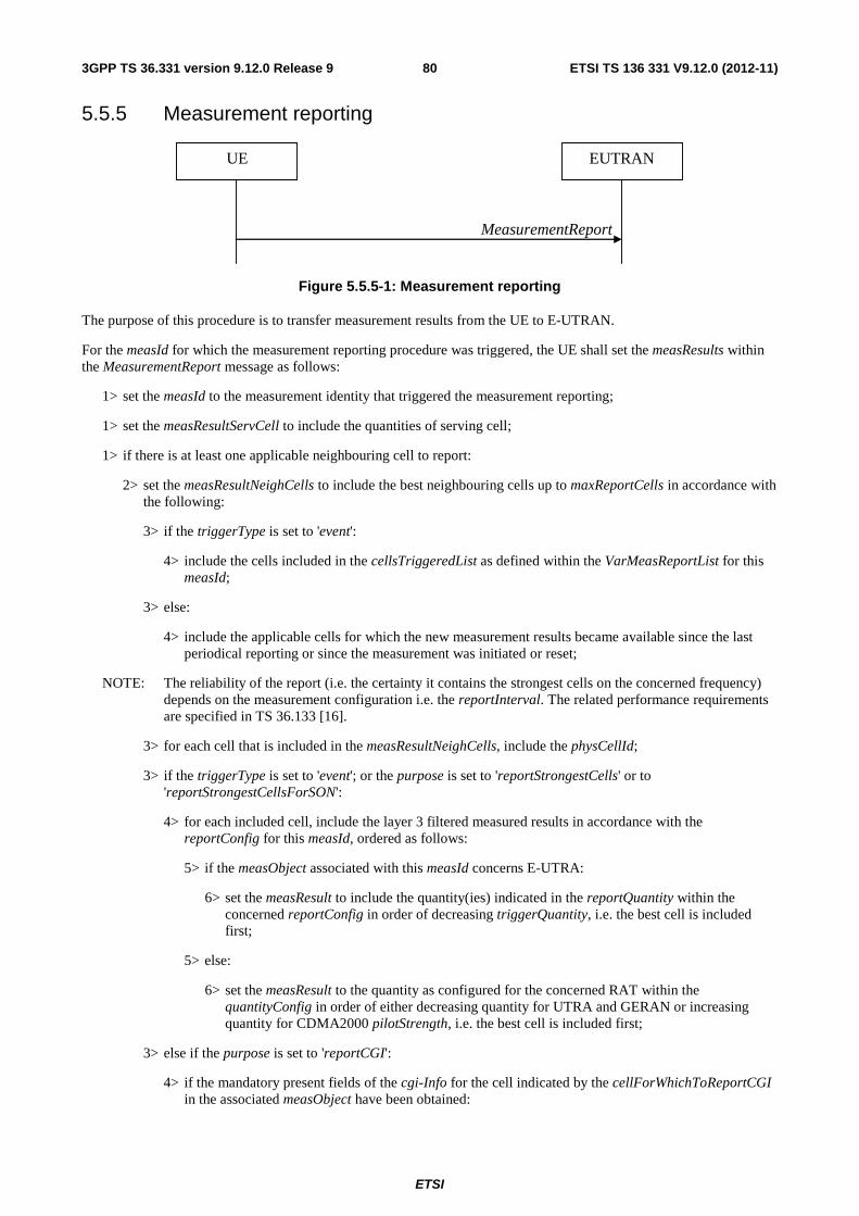
ETSI
ETSI TS 136 331 V9.12.0 (2012-11)803GPP TS 36.331 version 9.12.0 Release 9
5.5.5 Measurement reporting
MeasurementReport
UE EUTRAN
Figure 5.5.5-1: Measurement reporting
The purpose of this procedure is to transfer measurement results from the UE to E-UTRAN.
For the measId for which the measurement reporting procedure was triggered, the UE shall set the measResults within the MeasurementReport message as follows:
1> set the measId to the measurement identity that triggered the measurement reporting;
1> set the measResultServCell to include the quantities of serving cell;
1> if there is at least one applicable neighbouring cell to report:
2> set the measResultNeighCells to include the best neighbouring cells up to maxReportCells in accordance with the following:
3> if the triggerType is set to 'event':
4> include the cells included in the cellsTriggeredList as defined within the VarMeasReportList for this measId;
3> else:
4> include the applicable cells for which the new measurement results became available since the last periodical reporting or since the measurement was initiated or reset;
NOTE: The reliability of the report (i.e. the certainty it contains the strongest cells on the concerned frequency) depends on the measurement configuration i.e. the reportInterval. The related performance requirements are specified in TS 36.133 [16].
3> for each cell that is included in the measResultNeighCells, include the physCellId;
3> if the triggerType is set to 'event'; or the purpose is set to 'reportStrongestCells' or to 'reportStrongestCellsForSON':
4> for each included cell, include the layer 3 filtered measured results in accordance with the reportConfig for this measId, ordered as follows:
5> if the measObject associated with this measId concerns E-UTRA:
6> set the measResult to include the quantity(ies) indicated in the reportQuantity within the concerned reportConfig in order of decreasing triggerQuantity, i.e. the best cell is included first;
5> else:
6> set the measResult to the quantity as configured for the concerned RAT within the quantityConfig in order of either decreasing quantity for UTRA and GERAN or increasing quantity for CDMA2000 pilotStrength, i.e. the best cell is included first;
3> else if the purpose is set to 'reportCGI':
4> if the mandatory present fields of the cgi-Info for the cell indicated by the cellForWhichToReportCGI in the associated measObject have been obtained:

ETSI
ETSI TS 136 331 V9.12.0 (2012-11)813GPP TS 36.331 version 9.12.0 Release 9
5> if the cell broadcasts a CSG identity:
6> include the csg-Identity;
6> include the csg-MemberStatus and set it to 'member' if the cell is a CSG member cell;
5> if the 'si-RequestForHO' is configured within the reportConfig associated with this measId:
6> include the cgi-Info containing all the fields that have been successfully acquired, except for the plmn-IdentityList;
5> else:
6> include the cgi-Info containing all the fields that have been successfully acquired;
1> if the ue-RxTxTimeDiffPeriodical is configured within the corresponding reportConfig for this measId;
2> set the ue-RxTxTimeDiffResult to the measurement result provided by lower layers;
2> set the currentSFN;
1> increment the numberOfReportsSent as defined within the VarMeasReportList for this measId by 1;
1> stop the periodical reporting timer, if running;
1> if the numberOfReportsSent as defined within the VarMeasReportList for this measId is less than the reportAmount as defined within the corresponding reportConfig for this measId:
2> start the periodical reporting timer with the value of reportInterval as defined within the corresponding reportConfig for this measId;
1> else:
2> if the triggerType is set to 'periodical':
3> remove the entry within the VarMeasReportList for this measId;
3> remove this measId from the measIdList within VarMeasConfig;
1> if the measured results are for CDMA2000 HRPD:
2> set the preRegistrationStatusHRPD to the UE's CDMA2000 upper layer's HRPD preRegistrationStatus;
1> if the measured results are for CDMA2000 1xRTT:
2> set the preRegistrationStatusHRPD to 'FALSE';
1> submit the MeasurementReport message to lower layers for transmission, upon which the procedure ends;
5.5.6 Measurement related actions
5.5.6.1 Actions upon handover and re-establishment
E-UTRAN applies the handover procedure as follows:
- when performing the handover procedure, as specified in 5.3.5.4, ensure that a measObjectId corresponding to the handover target carrier frequency is configured as a result of the procedures described in this sub-clause and in 5.3.5.4;
E-UTRAN applies the re-establishment procedure as follows:
- when performing the connection re-establishment procedure, as specified in 5.3.7, ensure that a measObjectId corresponding to the target carrier frequency is configured as a result of the procedure described in this sub-clause and the subsequent connection reconfiguration procedure immediately following the re-establishment procedure;

ETSI
ETSI TS 136 331 V9.12.0 (2012-11)823GPP TS 36.331 version 9.12.0 Release 9
The UE shall:
1> for each measId included in the measIdList within VarMeasConfig:
2> if the triggerType is set to 'periodical':
3> remove this measId from the measIdList within VarMeasConfig:
1> if the procedure was triggered due to inter-frequency handover or successful re-establishment to an inter-frequency cell, update the measId values in the measIdList within VarMeasConfig as follows:
2> if a measObjectId value corresponding to the target carrier frequency exists in the measObjectList within VarMeasConfig:
3> for each measId value in the measIdList:
4> if the measId value is linked to the measObjectId value corresponding to the source carrier frequency:
5> link this measId value to the measObjectId value corresponding to the target carrier frequency;
4> else if the measId value is linked to the measObjectId value corresponding to the target carrier frequency:
5> link this measId value to the measObjectId value corresponding to the source carrier frequency;
2> else:
3> remove all measId values that are linked to the measObjectId value corresponding to the source carrier frequency;
1> remove all measurement reporting entries within VarMeasReportList;
1> stop the periodical reporting timer or timer T321, whichever one is running, as well as associated information (e.g. timeToTrigger) for all measId;
1> release the measurement gaps, if activated;
NOTE: If the UE requires measurement gaps to perform inter-frequency or inter-RAT measurements, the UE resumes the inter-frequency and inter-RAT measurements after the E-UTRAN has setup the measurement gaps.
5.5.6.2 Speed dependant scaling of measurement related parameters
The UE shall adjust the value of the following parameter configured by the E-UTRAN depending on the UE speed: timeToTrigger. The UE shall apply 3 different levels, which are selected as follows:
The UE shall:
1> perform mobility state detection using the mobility state detection as specified in TS 36.304 [4] with the following modifications:
2> counting handovers instead of cell reselections;
2> applying the parameter applicable for RRC_CONNECTED as included in speedStatePars within VarMeasConfig;
1> if high mobility state is detected:
2> use the timeToTrigger value multiplied by sf-High within VarMeasConfig;
1> else if medium mobility state is detected:
2> use the timeToTrigger value multiplied by sf-Medium within VarMeasConfig;
1> else
2> no scaling is applied;

ETSI
ETSI TS 136 331 V9.12.0 (2012-11)833GPP TS 36.331 version 9.12.0 Release 9
5.6 Other
5.6.1 DL information transfer
5.6.1.1 General
DLInformationTransfer
UE EUTRAN
Figure 5.6.1.1-1: DL information transfer
The purpose of this procedure is to transfer NAS or (tunnelled) non-3GPP dedicated information from E-UTRAN to a UE in RRC_CONNECTED.
5.6.1.2 Initiation
E-UTRAN initiates the DL information transfer procedure whenever there is a need to transfer NAS or non-3GPP dedicated information. E-UTRAN initiates the DL information transfer procedure by sending the DLInformationTransfer message.
5.6.1.3 Reception of the DLInformationTransfer by the UE
Upon receiving DLInformationTransfer message, the UE shall:
1> if the dedicatedInfoType is set to 'dedicatedInfoNAS':
2> forward the dedicatedInfoNAS to the NAS upper layers.
1> if the dedicatedInfoType is set to 'dedicatedInfoCDMA2000-1XRTT' or to 'dedicatedInfoCDMA2000-HRPD:
2> forward the dedicatedInfoCDMA2000 to the CDMA2000 upper layers;
5.6.2 UL information transfer
5.6.2.1 General
ULInformationTransfer
UE EUTRAN
Figure 5.6.2.1-1: UL information transfer
The purpose of this procedure is to transfer NAS or (tunnelled) non-3GPP dedicated information from the UE to E-UTRAN.
5.6.2.2 Initiation
A UE in RRC_CONNECTED initiates the UL information transfer procedure whenever there is a need to transfer NAS or non-3GPP dedicated information, except at RRC connection establishment in which case the NAS information is

ETSI
ETSI TS 136 331 V9.12.0 (2012-11)843GPP TS 36.331 version 9.12.0 Release 9
piggybacked to the RRCConnectionSetupComplete message. The UE initiates the UL information transfer procedure by sending the ULInformationTransfer message. When CDMA2000 information has to be transferred, the UE shall initiate the procedure only if SRB2 is established.
5.6.2.3 Actions related to transmission of ULInformationTransfer message
The UE shall set the contents of the ULInformationTransfer message as follows:
1> if there is a need to transfer NAS information:
2> set the dedicatedInfoType to include the 'dedicatedInfoNAS';
1> if there is a need to transfer CDMA2000 1XRTT information:
2> set the dedicatedInfoType to include the 'dedicatedInfoCDMA2000-1XRTT';
1> if there is a need to transfer CDMA2000 HRPD information:
2> set the dedicatedInfoType to include the 'dedicatedInfoCDMA2000-HRPD';
1> submit the ULInformationTransfer message to lower layers for transmission, upon which the procedure ends;
5.6.2.4 Failure to deliver ULInformationTransfer message
The UE shall:
1> if mobility (i.e. handover, RRC connection re-establishment) occurs before the successful delivery of ULInformationTransfer messages has been confirmed by lower layers:
2> inform upper layers about the possible failure to deliver the information contained in the concerned ULInformationTransfer messages;
5.6.3 UE capability transfer
5.6.3.1 General
UECapabilityInformation
UECapabilityEnquiry
UE EUTRAN
Figure 5.6.3.1-1: UE capability transfer
The purpose of this procedure is to transfer UE radio access capability information from the UE to E-UTRAN.
If the UE has changed its E-UTRAN radio access capabilities, the UE shall request higher layers to initiate the necessary NAS procedures (see TS 23.401 [41]) that would result in the update of UE radio access capabilities using a new RRC connection.
NOTE: Change of the UE's GERAN UE radio capabilities in RRC_IDLE is supported by use of Tracking Area Update.

ETSI
ETSI TS 136 331 V9.12.0 (2012-11)853GPP TS 36.331 version 9.12.0 Release 9
5.6.3.2 Initiation
E-UTRAN initiates the procedure to a UE in RRC_CONNECTED when it needs (additional) UE radio access capability information.
5.6.3.3 Reception of the UECapabilityEnquiry by the UE
The UE shall:
1> set the contents of UECapabilityInformation message as follows:
2> if the ue-CapabilityRequest includes 'eutra':
3> include the UE-EUTRA-Capability within a ue-CapabilityRAT-Container and with the rat-Type set to 'eutra';
3> if the UE supports FDD and TDD:
4> set all fields of UECapabilityInformation, except field fdd-Add-UE-EUTRA-Capabilities and tdd-Add-UE-EUTRA-Capabilities (including their sub-fields), to include the values applicable for both FDD and TDD (i.e. functionality supported by both modes);
4> if (some of) the UE capability fields have a different value for FDD and TDD:
5> if for FDD, the UE supports additional functionality compared to what is indicated by the previous fields of UECapabilityInformation:
6> include field fdd-Add-UE-EUTRA-Capabilities and set it to include fields reflecting the additional functionality applicable for FDD;
5> if for TDD, the UE supports additional functionality compared to what is indicated by the previous fields of UECapabilityInformation:
6> include field tdd-Add-UE-EUTRA-Capabilities and set it to include fields reflecting the additional functionality applicable for TDD;
NOTE: The UE includes fields of XDD-Add-UE-EUTRA-Capabilities in accordance with the following:
- The field is included only if one or more of its sub-fields has a value that is different compared to the value signalled elsewhere within UE-EUTRA-Capability;
(this value signalled elsewhere is also referred to as the Common value, that is supported for both XDD modes)
- For the fields that are included in XDD-Add-UE-EUTRA-Capabilities, the UE sets:
- the sub-fields that are not allowed to be different the same as the Common value;
- the sub-fields that are allowed to be different to a value indicating at least the same functionality as indicated by the Common value;
3> else (UE supports single xDD mode):
4> set all fields of UECapabilityInformation, except field fdd-Add-UE-EUTRA-Capabilities and tdd-Add-UE-EUTRA-Capabilities (including their sub-fields), to include the values applicable for the xDD mode supported by the UE;
2> if the ue-CapabilityRequest includes 'geran-cs' and if the UE supports GERAN CS domain:
3> include the UE radio access capabilities for GERAN CS within a ue-CapabilityRAT-Container and with the rat-Type set to 'geran-cs';
2> if the ue-CapabilityRequest includes 'geran-ps' and if the UE supports GERAN PS domain:
3> include the UE radio access capabilities for GERAN PS within a ue-CapabilityRAT-Container and with the rat-Type set to 'geran-ps';
2> if the ue-CapabilityRequest includes 'utra' and if the UE supports UTRA:
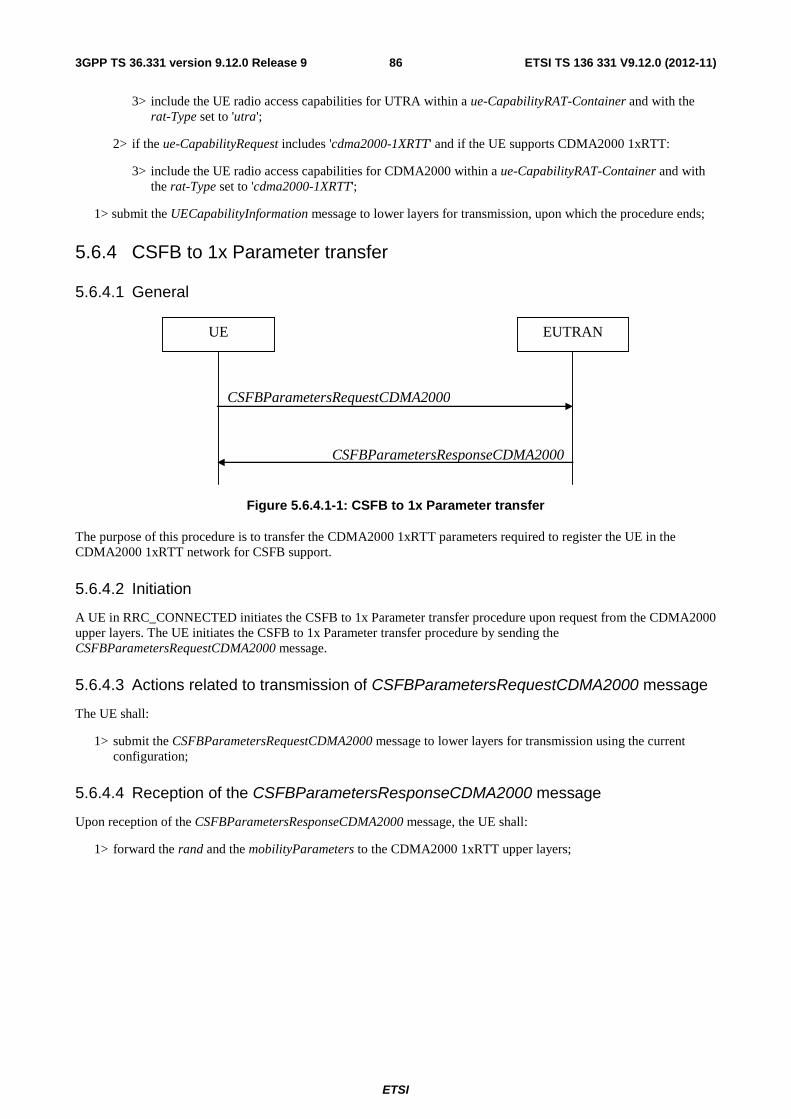
ETSI
ETSI TS 136 331 V9.12.0 (2012-11)863GPP TS 36.331 version 9.12.0 Release 9
3> include the UE radio access capabilities for UTRA within a ue-CapabilityRAT-Container and with the rat-Type set to 'utra';
2> if the ue-CapabilityRequest includes 'cdma2000-1XRTT' and if the UE supports CDMA2000 1xRTT:
3> include the UE radio access capabilities for CDMA2000 within a ue-CapabilityRAT-Container and with the rat-Type set to 'cdma2000-1XRTT';
1> submit the UECapabilityInformation message to lower layers for transmission, upon which the procedure ends;
5.6.4 CSFB to 1x Parameter transfer
5.6.4.1 General
CSFBParametersResponseCDMA2000
CSFBParametersRequestCDMA2000
UE EUTRAN
Figure 5.6.4.1-1: CSFB to 1x Parameter transfer
The purpose of this procedure is to transfer the CDMA2000 1xRTT parameters required to register the UE in the CDMA2000 1xRTT network for CSFB support.
5.6.4.2 Initiation
A UE in RRC_CONNECTED initiates the CSFB to 1x Parameter transfer procedure upon request from the CDMA2000 upper layers. The UE initiates the CSFB to 1x Parameter transfer procedure by sending the CSFBParametersRequestCDMA2000 message.
5.6.4.3 Actions related to transmission of CSFBParametersRequestCDMA2000 message
The UE shall:
1> submit the CSFBParametersRequestCDMA2000 message to lower layers for transmission using the current configuration;
5.6.4.4 Reception of the CSFBParametersResponseCDMA2000 message
Upon reception of the CSFBParametersResponseCDMA2000 message, the UE shall:
1> forward the rand and the mobilityParameters to the CDMA2000 1xRTT upper layers;

ETSI
ETSI TS 136 331 V9.12.0 (2012-11)873GPP TS 36.331 version 9.12.0 Release 9
5.6.5 UE Information
5.6.5.1 General
UEInformationResponse
UEInformationRequest
UE EUTRAN
Figure 5.6.5.1-1: UE information procedure
The UE information procedure is used by E-UTRAN to request the UE to report information.
5.6.5.2 Initiation
E-UTRAN initiates the procedure by sending the UEInformationRequest message.
5.6.5.3 Reception of the UEInformationRequest message
Upon receiving the UEInformationRequest message, the UE shall:
1> if rach-ReportReq is set to true, set the contents of the rach-Report in theUEInformationResponse message as follows:
2> set the numberOfPreamblesSent to indicate the number of preambles sent by MAC for the last successfully completed random access procedure
2> if contention is detected by MAC for at least one of the transmitted preambles for the last successfully completed random access procedure:
3> set the contentionDetected to true;
2> else:
3> set the contentionDetected to false;
1> if rlf-ReportReq is set to true and there is radio link failure information available, set the contents of the rlf-Report in theUEInformationResponse message as follows:
2> set the measResultLastServCell;
2> set the measResultNeighCells to include best neighbouring cells, ordered such that the best cell is listed first, and based on measurements collected up to the moment the UE detected radio link failure;
3> if the UE was configured to perform measurements for one or more EUTRA frequencies, include the measResultListEUTRA and include the corresponding carrierFreq and measResultList;
3> if the UE was configured to perform measurement reporting for one or more neighbouring UTRA frequencies, include the measResultListUTRA and include the corresponding carrierFreq and measResultList;
3> if the UE was configured to perform measurement reporting for one or more neighbouring GERAN frequencies, include the measResultListGERAN;
3> if the UE was configured to perform measurement reporting for one or more neighbouring CDMA2000 frequencies, include the measResultsCDMA2000 and include the corresponding carrierFreq and measResultList;

ETSI
ETSI TS 136 331 V9.12.0 (2012-11)883GPP TS 36.331 version 9.12.0 Release 9
NOTE The measured quantities are filtered by L3 filter as configured in mobility measurement configuration. Blacklisted cells are not required to be reported.
1> submit the UEInformationResponse message to lower layers for transmission upon which the procedure ends;
5.7 Generic error handling
5.7.1 General
The generic error handling defined in the subsequent sub-clauses applies unless explicitly specified otherwise e.g. within the procedure specific error handling.
The UE shall consider a value as not comprehended when it is set:
- to an extended value that is not defined in the version of the transfer syntax supported by the UE.
- to a spare or reserved value unless the specification defines specific behaviour that the UE shall apply upon receiving the concerned spare/ reserved value.
The UE shall consider a field as not comprehended when it is defined:
- as spare or reserved unless the specification defines specific behaviour that the UE shall apply upon receiving the concerned spare/ reserved field.
5.7.2 ASN.1 violation or encoding error
The UE shall:
1> when receiving an RRC message on the BCCH, PCCH, CCCH, or MCCH for which the abstract syntax is invalid [13]:
2> ignore the message;
NOTE This section applies in case one or more fields is set to a value, other than a spare, reserved or extended value, not defined in this version of the transfer syntax. E.g. in the case the UE receives value 12 for a field defined as INTEGER (1..11). In cases like this, it may not be possible to reliably detect which field is in the error hence the error handling is at the message level.
5.7.3 Field set to a not comprehended value
The UE shall, when receiving an RRC message on any logical channel:
1> if the message includes a field that has a value that the UE does not comprehend:
2> if a default value is defined for this field:
3> treat the message while using the default value defined for this field;
2> else if the concerned field is optional:
3> treat the message as if the field were absent and in accordance with the need code for absence of the concerned field;
2> else:
3> treat the message as if the field were absent and in accordance with sub-clause 5.7.4;
5.7.4 Mandatory field missing
The UE shall:

ETSI
ETSI TS 136 331 V9.12.0 (2012-11)893GPP TS 36.331 version 9.12.0 Release 9
1> if the message includes a field that is mandatory to include in the message (e.g. because conditions for mandatory presence are fulfilled) and that field is absent or treated as absent:
2> if the RRC message was received on DCCH or CCCH:
3> ignore the message;
2> else:
3> if the field concerns a (sub-field of) an entry of a list (i.e. a SEQUENCE OF):
4> treat the list as if the entry including the missing or not comprehended field was not present;
3> else if the field concerns a sub-field of another field, referred to as the 'parent' field i.e. the field that is one nesting level up compared to the erroneous field:
4> consider the 'parent' field to be set to a not comprehended value;
4> apply the generic error handling to the subsequent 'parent' field(s), until reaching the top nesting level i.e. the message level;
3> else (field at message level):
4> ignore the message;
NOTE: The error handling defined in these sub-clauses implies that the UE ignores a message with the message type or version set to a not comprehended value.
5.7.5 Not comprehended field
The UE shall, when receiving an RRC message on any logical channel:
1> if the message includes a field that the UE does not comprehend:
2> treat the rest of the message as if the field was absent;
NOTE: This section does not apply to the case of an extension to the value range of a field. Such cases are addressed instead by the requirements in section 5.7.3.
5.8 MBMS
5.8.1 Introduction
5.8.1.1 General
In general the control information relevant only for UEs supporting MBMS is separated as much as possible from unicast control information. Most of the MBMS control information is provided on a logical channel specific for MBMS common control information: the MCCH. E-UTRA employs one MCCH logical channel per MBSFN area. In case the network configures multiple MBSFN areas, the UE acquires the MBMS control information from the MCCHs that are configured to identify if services it is interested to receive are ongoing. The action applicable when the UE is unable to simultaneously receive MBMS and unicast services is up to UE implementation. In this release of the specification, an MBMS capable UE is only required to support reception of a single MBMS service at a time, and reception of more than one MBMS service (also possibly on more than one MBSFN area) in parallel is left for UE implementation. The MCCH carries a single message, the MBSFNAreaConfiguration message, which indicates the MBMS sessions that are ongoing as well as the (corresponding) radio resource configuration.
A limited amount of MBMS control information is provided on the BCCH. This primarily concerns the information needed to acquire the MCCH(s). This information is carried by means of a single MBMS specific SystemInformationBlock: SystemInformationBlockType13. An MBSFN area is identified solely by the mbsfn-AreaId in SystemInformationBlockType13. At mobility, the UE considers that the MBSFN area is continuous when the source cell and the target cell broadcast the same value in the mbsfn-AreaId.

ETSI
ETSI TS 136 331 V9.12.0 (2012-11)903GPP TS 36.331 version 9.12.0 Release 9
5.8.1.2 Scheduling
The MCCH information is transmitted periodically, using a configurable repetition period. Scheduling information is not provided for MCCH i.e. both the time domain scheduling as well as the lower layer configuration are semi-statically configured, as defined within SystemInformationBlockType13.
For MBMS user data, which is carried by the MTCH logical channel, E-UTRAN periodically provides MCH scheduling information (MSI) at lower layers (MAC). This MCH information only concerns the time domain scheduling i.e. the frequency domain scheduling and the lower layer configuration are semi-statically configured. The periodicity of the MSI is configurable and defined by the MCH scheduling period.
5.8.1.3 MCCH information validity and notification of changes
Change of MCCH information only occurs at specific radio frames, i.e. the concept of a modification period is used. Within a modification period, the same MCCH information may be transmitted a number of times, as defined by its scheduling (which is based on a repetition period). The modification period boundaries are defined by SFN values for which SFN mod m= 0, where m is the number of radio frames comprising the modification period. The modification period is configured by means of SystemInformationBlockType13.
When the network changes (some of) the MCCH information, it notifies the UEs about the change during a first modification period. In the next modification period, the network transmits the updated MCCH information. These general principles are illustrated in figure 5.8.1.3-1, in which different colours indicate different MCCH information. Upon receiving a change notification, a UE interested to receive MBMS services acquires the new MCCH information immediately from the start of the next modification period. The UE applies the previously acquired MCCH information until the UE acquires the new MCCH information.
MCCH modification period (n)
Change notification Updated information
MCCH modification period (n+1)
MCCH repetition period
Figure 5.8.1.3-1: Change of MCCH Information
Indication of an MBMS specific RNTI, the M-RNTI (see TS 36.321 [6]), on PDCCH is used to inform UEs in RRC_IDLE and UEs in RRC_CONNECTED about an MCCH information change. When receiving an MCCH information change notification, the UE knows that the MCCH information will change at the next modification period boundary. The notification on PDCCH indicates which of the MCCHs will change, which is done by means of an 8-bit bitmap. Within this bitmap, the bit at the position indicated by the field notificationIndicator is used to indicate changes for that MBSFN area: if the bit is set to "1", the corresponding MCCH will change. No further details are provided e.g. regarding which MCCH information will change. The MCCH information change notification is used only to inform the UE about a change of MCCH information upon session start.
The MCCH information change notifications on PDCCH are transmitted periodically and are carried on MBSFN subframes only. These MCCH information change notification occasions are common for all MCCHs that are configured, and configurable by parameters included in SystemInformationBlockType13: a repetition coefficient, a radio frame offset and a subframe index. These common notification occasions are based on the MCCH with the shortest modification period.
NOTE 1: E-UTRAN may modify the MBMS configuration information provided on MCCH at the same time as updating the MBMS configuration information carried on BCCH i.e. at a coinciding BCCH and MCCH modification period. Upon detecting that a new MCCH is configured on BCCH, a UE interested to receive one or more MBMS services should acquire the MCCH, unless it knows that the services it is interested in are not provided by the corresponding MBSFN area.
A UE that is receiving an MBMS service shall acquire the MCCH information from the start of each modification period. A UE that is not receiving an MBMS service, as well as UEs that are receiving an MBMS service but potentially interested to receive other services not started yet in another MBSFN area, shall verify that the stored MCCH information remains valid by attempting to find the MCCH information change notification at least

ETSI
ETSI TS 136 331 V9.12.0 (2012-11)913GPP TS 36.331 version 9.12.0 Release 9
notificationRepetitionCoeff times during the modification period of the applicable MCCH(s), if no MCCH information change notification is received.
NOTE 2: In case the UE is aware which MCCH(s) E-UTRAN uses for the service(s) it is interested to receive, the UE may only need to monitor change notifications for a subset of the MCCHs that are configured, referred to as the 'applicable MCCH(s)' in the above.
5.8.2 MCCH information acquisition
5.8.2.1 General
E-UTRAN
MBSFNAreaConfiguration
UE
Figure 5.8.2.1-1: MCCH information acquisition
The UE applies the MCCH information acquisition procedure to acquire the MBMS control information that is broadcasted by the E-UTRAN. The procedure applies to MBMS capable UEs that are in RRC_IDLE or in RRC_CONNECTED.
5.8.2.2 Initiation
A UE interested to receive MBMS services shall apply the MCCH information acquisition procedure upon entering the corresponding MBSFN area (e.g. upon power on, following UE mobility) and upon receiving a notification that the MCCH information has changed. A UE that is receiving an MBMS service shall apply the MCCH information acquisition procedure to acquire the MCCH, that corresponds with the service that is being received, at the start of each modification period.
Unless explicitly stated otherwise in the procedural specification, the MCCH information acquisition procedure overwrites any stored MCCH information, i.e. delta configuration is not applicable for MCCH information and the UE discontinues using a field if it is absent in MCCH information unless explicitly specified otherwise.
5.8.2.3 MCCH information acquisition by the UE
An MBMS capable UE shall:
1> if the procedure is triggered by a MCCH information change notification:
2> start acquiring the MBSFNAreaConfiguration message from the beginning of the modification period following the one in which the change notification was received;
NOTE 1: The UE continues using the previously received MCCH information until the new MCCH information has been acquired.
1> if the UE enters an MBSFN area:
2> acquire the MBSFNAreaConfiguration message at the next repetition period;
1> if the UE is receiving an MBMS service:
2> start acquiring the MBSFNAreaConfiguration message, that corresponds with the service that is being received, from the beginning of each modification period;
5.8.2.4 Actions upon reception of the MBSFNAreaConfiguration message
No UE requirements related to the contents of this MBSFNAreaConfiguration apply other than those specified elsewhere e.g. within procedures using the concerned system information, the corresponding field descriptions.
ETSI
ETSI TS 136 331 V9.12.0 (2012-11)923GPP TS 36.331 version 9.12.0 Release 9
5.8.3 MBMS PTM radio bearer configuration
5.8.3.1 General
The MBMS PTM radio bearer configuration procedure is used by the UE to configure RLC, MAC and the physical layer upon starting and or stopping to receive a MRB. The procedure applies to UEs interested to receive one or more MBMS services.
NOTE: In case the UE is unable to receive an MBMS service due to capability limitations, upper layers may take appropriate action e.g. terminate a lower priority unicast service.
5.8.3.2 Initiation
The UE applies the MRB establishment procedure to start receiving a session of a service it has an interest in. The procedure may be initiated e.g. upon start of the MBMS session, upon (re-)entry of the corresponding MBSFN service area, upon becoming interested in the MBMS service, upon removal of UE capability limitations inhibiting reception of the concerned service.
The UE applies the MRB release procedure to stop receiving a session. The procedure may be initiated e.g. upon stop of the MBMS session, upon leaving the corresponding MBSFN service area, upon losing interest in the MBMS service, when capability limitations start inhibiting reception of the concerned service.
5.8.3.3 MRB establishment
Upon MRB establishment, the UE shall:
1> establish an RLC entity in accordance with the configuration specified in 9.1.1.4;
1> configure an MTCH logical channel in accordance with the received locgicalChannelIdentity, applicable for the MRB, as included in the MBSFNAreaConfiguration message;
1> configure the physical layer in accordance with the pmch-Config, applicable for the MRB, as included in the MBSFNAreaConfiguration message;
1> inform upper layers about the establishment of the MRB by indicating the corresponding tmgi and sessionId;
5.8.3.4 MRB release
Upon MRB release, the UE shall:
1> release the RLC entity as well as the related MAC and physical layer configuration;
1> inform upper layers about the release of the MRB by indicating the corresponding tmgi and sessionId;
6 Protocol data units, formats and parameters (tabular & ASN.1)
6.1 General The contents of each RRC message is specified in sub-clause 6.2 using ASN.1 to specify the message syntax and using tables when needed to provide further detailed information about the information elements specified in the message syntax. The syntax of the information elements that are defined as stand-alone abstract types is further specified in a similar manner in sub-clause 6.3.
The need for information elements to be present in a message or an abstract type, i.e., the ASN.1 fields that are specified as OPTIONAL in the abstract notation (ASN.1), is specified by means of comment text tags attached to the OPTIONAL statement in the abstract syntax. All comment text tags are available for use in the downlink direction only. The meaning of each tag is specified in table 6.1-1.
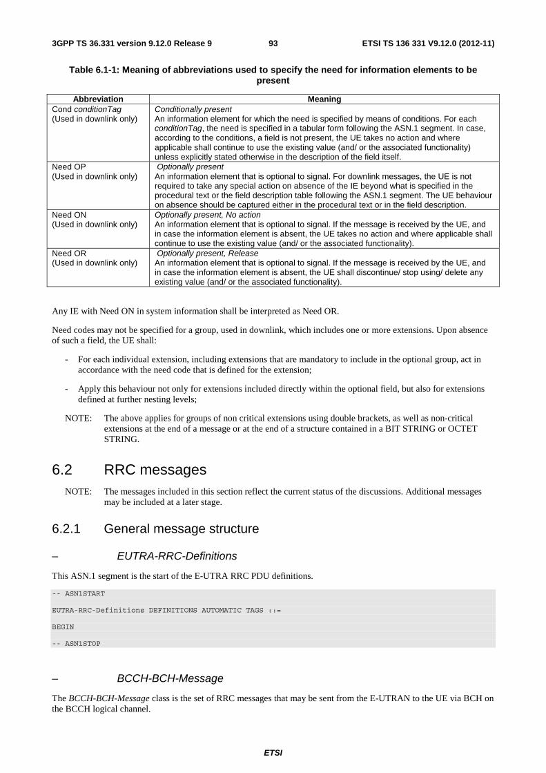
ETSI
ETSI TS 136 331 V9.12.0 (2012-11)933GPP TS 36.331 version 9.12.0 Release 9
Table 6.1-1: Meaning of abbreviations used to specify the need for information elements to be present
Abbreviation Meaning Cond conditionTag (Used in downlink only)
Conditionally present An information element for which the need is specified by means of conditions. For each conditionTag, the need is specified in a tabular form following the ASN.1 segment. In case, according to the conditions, a field is not present, the UE takes no action and where applicable shall continue to use the existing value (and/ or the associated functionality) unless explicitly stated otherwise in the description of the field itself.
Need OP (Used in downlink only)
Optionally present An information element that is optional to signal. For downlink messages, the UE is not required to take any special action on absence of the IE beyond what is specified in the procedural text or the field description table following the ASN.1 segment. The UE behaviour on absence should be captured either in the procedural text or in the field description.
Need ON (Used in downlink only)
Optionally present, No action An information element that is optional to signal. If the message is received by the UE, and in case the information element is absent, the UE takes no action and where applicable shall continue to use the existing value (and/ or the associated functionality).
Need OR (Used in downlink only)
Optionally present, Release An information element that is optional to signal. If the message is received by the UE, and in case the information element is absent, the UE shall discontinue/ stop using/ delete any existing value (and/ or the associated functionality).
Any IE with Need ON in system information shall be interpreted as Need OR.
Need codes may not be specified for a group, used in downlink, which includes one or more extensions. Upon absence of such a field, the UE shall:
- For each individual extension, including extensions that are mandatory to include in the optional group, act in accordance with the need code that is defined for the extension;
- Apply this behaviour not only for extensions included directly within the optional field, but also for extensions defined at further nesting levels;
NOTE: The above applies for groups of non critical extensions using double brackets, as well as non-critical extensions at the end of a message or at the end of a structure contained in a BIT STRING or OCTET STRING.
6.2 RRC messages NOTE: The messages included in this section reflect the current status of the discussions. Additional messages
may be included at a later stage.
6.2.1 General message structure
– EUTRA-RRC-Definitions
This ASN.1 segment is the start of the E-UTRA RRC PDU definitions.
-- ASN1START EUTRA-RRC-Definitions DEFINITIONS AUTOMATIC TAGS ::= BEGIN -- ASN1STOP
– BCCH-BCH-Message
The BCCH-BCH-Message class is the set of RRC messages that may be sent from the E-UTRAN to the UE via BCH on the BCCH logical channel.

ETSI
ETSI TS 136 331 V9.12.0 (2012-11)943GPP TS 36.331 version 9.12.0 Release 9
-- ASN1START BCCH-BCH-Message ::= SEQUENCE { message BCCH-BCH-MessageType } BCCH-BCH-MessageType ::= MasterInformationBlock -- ASN1STOP
– BCCH-DL-SCH-Message
The BCCH-DL-SCH-Message class is the set of RRC messages that may be sent from the E-UTRAN to the UE via DL-SCH on the BCCH logical channel.
-- ASN1START BCCH-DL-SCH-Message ::= SEQUENCE { message BCCH-DL-SCH-MessageType } BCCH-DL-SCH-MessageType ::= CHOICE { c1 CHOICE { systemInformation SystemInformation, systemInformationBlockType1 SystemInformationBlockType1 }, messageClassExtension SEQUENCE {} } -- ASN1STOP
– MCCH-Message
The MCCH-Message class is the set of RRC messages that may be sent from the E-UTRAN to the UE on the MCCH logical channel.
-- ASN1START MCCH-Message ::= SEQUENCE { message MCCH-MessageType } MCCH-MessageType ::= CHOICE { c1 CHOICE { mbsfnAreaConfiguration-r9 MBSFNAreaConfiguration-r9 }, messageClassExtension SEQUENCE {} } -- ASN1STOP
– PCCH-Message
The PCCH-Message class is the set of RRC messages that may be sent from the E-UTRAN to the UE on the PCCH logical channel.
-- ASN1START PCCH-Message ::= SEQUENCE { message PCCH-MessageType } PCCH-MessageType ::= CHOICE { c1 CHOICE { paging Paging }, messageClassExtension SEQUENCE {} }

ETSI
ETSI TS 136 331 V9.12.0 (2012-11)953GPP TS 36.331 version 9.12.0 Release 9
-- ASN1STOP
– DL-CCCH-Message
The DL-CCCH-Message class is the set of RRC messages that may be sent from the E-UTRAN to the UE on the downlink CCCH logical channel.
-- ASN1START DL-CCCH-Message ::= SEQUENCE { message DL-CCCH-MessageType } DL-CCCH-MessageType ::= CHOICE { c1 CHOICE { rrcConnectionReestablishment RRCConnectionReestablishment, rrcConnectionReestablishmentReject RRCConnectionReestablishmentReject, rrcConnectionReject RRCConnectionReject, rrcConnectionSetup RRCConnectionSetup }, messageClassExtension SEQUENCE {} } -- ASN1STOP
– DL-DCCH-Message
The DL-DCCH-Message class is the set of RRC messages that may be sent from the E-UTRAN to the UE on the downlink DCCH logical channel.
-- ASN1START DL-DCCH-Message ::= SEQUENCE { message DL-DCCH-MessageType } DL-DCCH-MessageType ::= CHOICE { c1 CHOICE { csfbParametersResponseCDMA2000 CSFBParametersResponseCDMA2000, dlInformationTransfer DLInformationTransfer, handoverFromEUTRAPreparationRequest HandoverFromEUTRAPreparationRequest, mobilityFromEUTRACommand MobilityFromEUTRACommand, rrcConnectionReconfiguration RRCConnectionReconfiguration, rrcConnectionRelease RRCConnectionRelease, securityModeCommand SecurityModeCommand, ueCapabilityEnquiry UECapabilityEnquiry, counterCheck CounterCheck, ueInformationRequest-r9 UEInformationRequest-r9, spare6 NULL, spare5 NULL, spare4 NULL, spare3 NULL, spare2 NULL, spare1 NULL }, messageClassExtension SEQUENCE {} } -- ASN1STOP
– UL-CCCH-Message
The UL-CCCH-Message class is the set of RRC messages that may be sent from the UE to the E-UTRAN on the uplink CCCH logical channel.
-- ASN1START UL-CCCH-Message ::= SEQUENCE { message UL-CCCH-MessageType } UL-CCCH-MessageType ::= CHOICE { c1 CHOICE {

ETSI
ETSI TS 136 331 V9.12.0 (2012-11)963GPP TS 36.331 version 9.12.0 Release 9
rrcConnectionReestablishmentRequest RRCConnectionReestablishmentRequest, rrcConnectionRequest RRCConnectionRequest }, messageClassExtension SEQUENCE {} } -- ASN1STOP
– UL-DCCH-Message
The UL-DCCH-Message class is the set of RRC messages that may be sent from the UE to the E-UTRAN on the uplink DCCH logical channel.
-- ASN1START UL-DCCH-Message ::= SEQUENCE { message UL-DCCH-MessageType } UL-DCCH-MessageType ::= CHOICE { c1 CHOICE { csfbParametersRequestCDMA2000 CSFBParametersRequestCDMA2000, measurementReport MeasurementReport, rrcConnectionReconfigurationComplete RRCConnectionReconfigurationComplete, rrcConnectionReestablishmentComplete RRCConnectionReestablishmentComplete, rrcConnectionSetupComplete RRCConnectionSetupComplete, securityModeComplete SecurityModeComplete, securityModeFailure SecurityModeFailure, ueCapabilityInformation UECapabilityInformation, ulHandoverPreparationTransfer ULHandoverPreparationTransfer, ulInformationTransfer ULInformationTransfer, counterCheckResponse CounterCheckResponse, ueInformationResponse-r9 UEInformationResponse-r9, proximityIndication-r9 ProximityIndication-r9, spare3 NULL, spare2 NULL, spare1 NULL }, messageClassExtension SEQUENCE {} } -- ASN1STOP
6.2.2 Message definitions
– CounterCheck
The CounterCheck message is used by the E-UTRAN to indicate the current COUNT MSB values associated to each DRB and to request the UE to compare these to its COUNT MSB values and to report the comparison results to E-UTRAN.
Signalling radio bearer: SRB1
RLC-SAP: AM
Logical channel: DCCH
Direction: E-UTRAN to UE
CounterCheck message
-- ASN1START CounterCheck ::= SEQUENCE { rrc-TransactionIdentifier RRC-TransactionIdentifier, criticalExtensions CHOICE { c1 CHOICE { counterCheck-r8 CounterCheck-r8-IEs, spare3 NULL, spare2 NULL, spare1 NULL }, criticalExtensionsFuture SEQUENCE {}

ETSI
ETSI TS 136 331 V9.12.0 (2012-11)973GPP TS 36.331 version 9.12.0 Release 9
} } CounterCheck-r8-IEs ::= SEQUENCE { drb-CountMSB-InfoList DRB-CountMSB-InfoList, nonCriticalExtension CounterCheck-v8a0-IEs OPTIONAL } CounterCheck-v8a0-IEs ::= SEQUENCE { lateNonCriticalExtension OCTET STRING OPTIONAL, -- Need OP nonCriticalExtension SEQUENCE {} OPTIONAL -- Need OP } DRB-CountMSB-InfoList ::= SEQUENCE (SIZE (1..maxDRB)) OF DRB-CountMSB-Info DRB-CountMSB-Info ::= SEQUENCE { drb-Identity DRB-Identity, countMSB-Uplink INTEGER(0..33554431), countMSB-Downlink INTEGER(0..33554431) } -- ASN1STOP
CounterCheck field descriptions drb-CountMSB-InfoList Indicates the MSBs of the COUNT values of the DRBs. count-MSB-Uplink Indicates the value of 25 MSBs from uplink COUNT associated to this DRB. count-MSB-Downlink Indicates the value of 25 MSBs from downlink COUNT associated to this DRB.
– CounterCheckResponse
The CounterCheckResponse message is used by the UE to respond to a CounterCheck message.
Signalling radio bearer: SRB1
RLC-SAP: AM
Logical channel: DCCH
Direction: UE to E-UTRAN
CounterCheckResponse message
-- ASN1START CounterCheckResponse ::= SEQUENCE { rrc-TransactionIdentifier RRC-TransactionIdentifier, criticalExtensions CHOICE { counterCheckResponse-r8 CounterCheckResponse-r8-IEs, criticalExtensionsFuture SEQUENCE {} } } CounterCheckResponse-r8-IEs ::= SEQUENCE { drb-CountInfoList DRB-CountInfoList, nonCriticalExtension CounterCheckResponse-v8a0-IEs OPTIONAL } CounterCheckResponse-v8a0-IEs ::= SEQUENCE { lateNonCriticalExtension OCTET STRING OPTIONAL, nonCriticalExtension SEQUENCE {} OPTIONAL } DRB-CountInfoList ::= SEQUENCE (SIZE (0..maxDRB)) OF DRB-CountInfo DRB-CountInfo ::= SEQUENCE { drb-Identity DRB-Identity, count-Uplink INTEGER(0..4294967295),
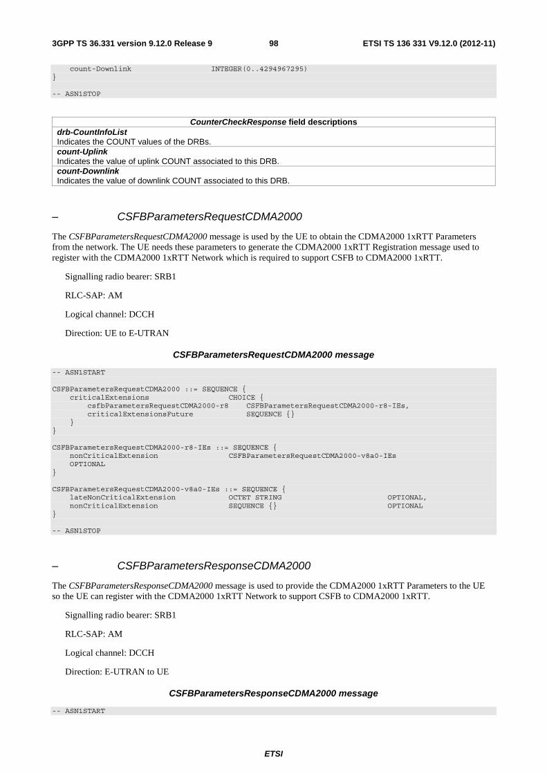
ETSI
ETSI TS 136 331 V9.12.0 (2012-11)983GPP TS 36.331 version 9.12.0 Release 9
count-Downlink INTEGER(0..4294967295) } -- ASN1STOP
CounterCheckResponse field descriptions drb-CountInfoList Indicates the COUNT values of the DRBs. count-Uplink Indicates the value of uplink COUNT associated to this DRB. count-Downlink Indicates the value of downlink COUNT associated to this DRB.
– CSFBParametersRequestCDMA2000
The CSFBParametersRequestCDMA2000 message is used by the UE to obtain the CDMA2000 1xRTT Parameters from the network. The UE needs these parameters to generate the CDMA2000 1xRTT Registration message used to register with the CDMA2000 1xRTT Network which is required to support CSFB to CDMA2000 1xRTT.
Signalling radio bearer: SRB1
RLC-SAP: AM
Logical channel: DCCH
Direction: UE to E-UTRAN
CSFBParametersRequestCDMA2000 message
-- ASN1START CSFBParametersRequestCDMA2000 ::= SEQUENCE { criticalExtensions CHOICE { csfbParametersRequestCDMA2000-r8 CSFBParametersRequestCDMA2000-r8-IEs, criticalExtensionsFuture SEQUENCE {} } } CSFBParametersRequestCDMA2000-r8-IEs ::= SEQUENCE { nonCriticalExtension CSFBParametersRequestCDMA2000-v8a0-IEs OPTIONAL } CSFBParametersRequestCDMA2000-v8a0-IEs ::= SEQUENCE { lateNonCriticalExtension OCTET STRING OPTIONAL, nonCriticalExtension SEQUENCE {} OPTIONAL } -- ASN1STOP
– CSFBParametersResponseCDMA2000
The CSFBParametersResponseCDMA2000 message is used to provide the CDMA2000 1xRTT Parameters to the UE so the UE can register with the CDMA2000 1xRTT Network to support CSFB to CDMA2000 1xRTT.
Signalling radio bearer: SRB1
RLC-SAP: AM
Logical channel: DCCH
Direction: E-UTRAN to UE
CSFBParametersResponseCDMA2000 message
-- ASN1START

ETSI
ETSI TS 136 331 V9.12.0 (2012-11)993GPP TS 36.331 version 9.12.0 Release 9
CSFBParametersResponseCDMA2000 ::= SEQUENCE { rrc-TransactionIdentifier RRC-TransactionIdentifier, criticalExtensions CHOICE { csfbParametersResponseCDMA2000-r8 CSFBParametersResponseCDMA2000-r8-IEs, criticalExtensionsFuture SEQUENCE {} } } CSFBParametersResponseCDMA2000-r8-IEs ::= SEQUENCE { rand RAND-CDMA2000, mobilityParameters MobilityParametersCDMA2000, nonCriticalExtension CSFBParametersResponseCDMA2000-v8a0-IEs OPTIONAL } CSFBParametersResponseCDMA2000-v8a0-IEs ::= SEQUENCE { lateNonCriticalExtension OCTET STRING OPTIONAL, -- Need OP nonCriticalExtension SEQUENCE {} OPTIONAL -- Need OP } -- ASN1STOP
– DLInformationTransfer
The DLInformationTransfer message is used for the downlink transfer of dedicated NAS information.
Signalling radio bearer: SRB2 or SRB1 (only if SRB2 not established yet. If SRB2 is suspended, E-UTRAN does not send this message until SRB2 is resumed.)
RLC-SAP: AM
Logical channel: DCCH
Direction: E-UTRAN to UE
DLInformationTransfer message
-- ASN1START DLInformationTransfer ::= SEQUENCE { rrc-TransactionIdentifier RRC-TransactionIdentifier, criticalExtensions CHOICE { c1 CHOICE { dlInformationTransfer-r8 DLInformationTransfer-r8-IEs, spare3 NULL, spare2 NULL, spare1 NULL }, criticalExtensionsFuture SEQUENCE {} } } DLInformationTransfer-r8-IEs ::= SEQUENCE { dedicatedInfoType CHOICE { dedicatedInfoNAS DedicatedInfoNAS, dedicatedInfoCDMA2000-1XRTT DedicatedInfoCDMA2000, dedicatedInfoCDMA2000-HRPD DedicatedInfoCDMA2000 }, nonCriticalExtension DLInformationTransfer-v8a0-IEs OPTIONAL } DLInformationTransfer-v8a0-IEs ::= SEQUENCE { lateNonCriticalExtension OCTET STRING OPTIONAL, -- Need OP nonCriticalExtension SEQUENCE {} OPTIONAL -- Need OP } -- ASN1STOP
– HandoverFromEUTRAPreparationRequest (CDMA2000)
The HandoverFromEUTRAPreparationRequest message is used to trigger the handover preparation procedure with a CDMA2000 RAT. This message is also used to trigger a tunneled preparation procedure with a CDMA2000 1xRTT

ETSI
ETSI TS 136 331 V9.12.0 (2012-11)1003GPP TS 36.331 version 9.12.0 Release 9
RAT to obtain traffic channel resources for the enhanced CS fallback to CDMA2000 1xRTT, which may also involve a concurrent preparation for handover to CDMA2000 HRPD.
Signalling radio bearer: SRB1
RLC-SAP: AM
Logical channel: DCCH
Direction: E-UTRAN to UE
HandoverFromEUTRAPreparationRequest message
-- ASN1START HandoverFromEUTRAPreparationRequest ::= SEQUENCE { rrc-TransactionIdentifier RRC-TransactionIdentifier, criticalExtensions CHOICE { c1 CHOICE { handoverFromEUTRAPreparationRequest-r8 HandoverFromEUTRAPreparationRequest-r8-IEs, spare3 NULL, spare2 NULL, spare1 NULL }, criticalExtensionsFuture SEQUENCE {} } } HandoverFromEUTRAPreparationRequest-r8-IEs ::= SEQUENCE { cdma2000-Type CDMA2000-Type, rand RAND-CDMA2000 OPTIONAL, -- Cond cdma2000-Type mobilityParameters MobilityParametersCDMA2000 OPTIONAL, -- Cond cdma2000-Type nonCriticalExtension HandoverFromEUTRAPreparationRequest-v890-IEs OPTIONAL } HandoverFromEUTRAPreparationRequest-v890-IEs ::= SEQUENCE { lateNonCriticalExtension OCTET STRING OPTIONAL, -- Need OP nonCriticalExtension HandoverFromEUTRAPreparationRequest-v920-IEs OPTIONAL } HandoverFromEUTRAPreparationRequest-v920-IEs ::= SEQUENCE { concurrPrepCDMA2000-HRPD-r9 BOOLEAN OPTIONAL, -- Cond cdma2000-Type nonCriticalExtension SEQUENCE {} OPTIONAL -- Need OP } -- ASN1STOP
HandoverFromEUTRAPreparationRequest field descriptions concurrPrepCDMA2000-HRPD Value TRUE indicates that upper layers should initiate concurrent preparation for handover to CDMA2000 HRPD in addition to preparation for enhanced CS fallback to CDMA2000 1xRTT.
Conditional presence Explanation cdma2000-Type The field is mandatory present if the cdma2000-Type = type1XRTT; otherwise it is not
present.
– MasterInformationBlock
The MasterInformationBlock includes the system information transmitted on BCH.

ETSI
ETSI TS 136 331 V9.12.0 (2012-11)1013GPP TS 36.331 version 9.12.0 Release 9
Signalling radio bearer: N/A
RLC-SAP: TM
Logical channel: BCCH
Direction: E-UTRAN to UE
MasterInformationBlock
-- ASN1START MasterInformationBlock ::= SEQUENCE { dl-Bandwidth ENUMERATED { n6, n15, n25, n50, n75, n100}, phich-Config PHICH-Config, systemFrameNumber BIT STRING (SIZE (8)), spare BIT STRING (SIZE (10)) } -- ASN1STOP
MasterInformationBlock field descriptions dl-Bandwidth Parameter: transmission bandwidth configuration, NRB in downlink, see TS 36.101 [42, table 5.6-1]. n6 corresponds to 6 resource blocks, n15 to 15 resource blocks and so on. systemFrameNumber Defines the 8 most significant bits of the SFN. As indicated in TS 36.211 [21, 6.6.1], the 2 least significant bits of the SFN are acquired implicitly in the P-BCH decoding, i.e. timing of 40ms P-BCH TTI indicates 2 least significant bits (within 40ms P-BCH TTI, the first radio frame: 00, the second radio frame: 01, the third radio frame: 10, the last radio frame: 11).
– MBSFNAreaConfiguration
The MBSFNAreaConfiguration message contains the MBMS control information applicable for an MBSFN area. E-UTRAN configures an MCCH for each MBSFN area i.e. the MCCH identifies the MBSFN area.
Signalling radio bearer: N/A
RLC-SAP: UM
Logical channel: MCCH
Direction: E-UTRAN to UE
MBSFNAreaConfiguration message
-- ASN1START MBSFNAreaConfiguration-r9 ::= SEQUENCE { commonSF-Alloc-r9 CommonSF-AllocPatternList-r9, commonSF-AllocPeriod-r9 ENUMERATED { rf4, rf8, rf16, rf32, rf64, rf128, rf256}, pmch-InfoList-r9 PMCH-InfoList-r9, nonCriticalExtension MBSFNAreaConfiguration-v930-IEs OPTIONAL } MBSFNAreaConfiguration-v930-IEs ::= SEQUENCE { lateNonCriticalExtension OCTET STRING OPTIONAL, -- Need OP nonCriticalExtension SEQUENCE {} OPTIONAL -- Need OP } CommonSF-AllocPatternList-r9 ::= SEQUENCE (SIZE (1..maxMBSFN-Allocations)) OF MBSFN-SubframeConfig -- ASN1STOP
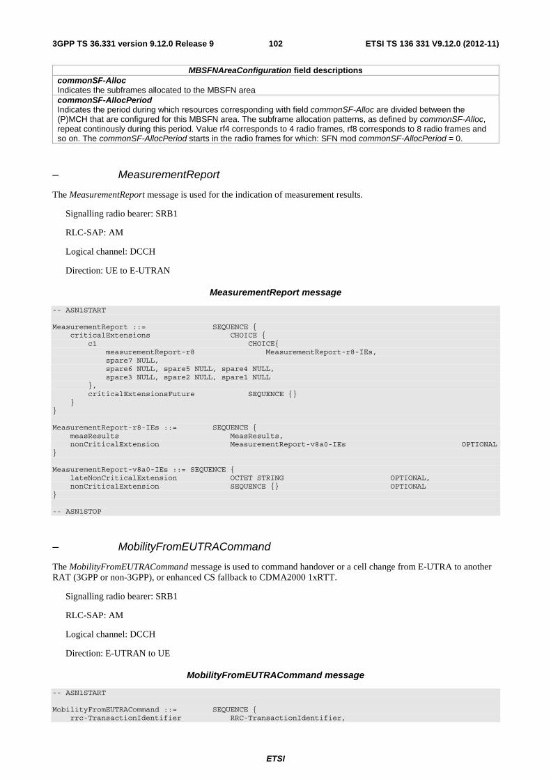
ETSI
ETSI TS 136 331 V9.12.0 (2012-11)1023GPP TS 36.331 version 9.12.0 Release 9
MBSFNAreaConfiguration field descriptions commonSF-Alloc Indicates the subframes allocated to the MBSFN area commonSF-AllocPeriod Indicates the period during which resources corresponding with field commonSF-Alloc are divided between the (P)MCH that are configured for this MBSFN area. The subframe allocation patterns, as defined by commonSF-Alloc, repeat continously during this period. Value rf4 corresponds to 4 radio frames, rf8 corresponds to 8 radio frames and so on. The commonSF-AllocPeriod starts in the radio frames for which: SFN mod commonSF-AllocPeriod = 0.
– MeasurementReport
The MeasurementReport message is used for the indication of measurement results.
Signalling radio bearer: SRB1
RLC-SAP: AM
Logical channel: DCCH
Direction: UE to E-UTRAN
MeasurementReport message
-- ASN1START MeasurementReport ::= SEQUENCE { criticalExtensions CHOICE { c1 CHOICE{ measurementReport-r8 MeasurementReport-r8-IEs, spare7 NULL, spare6 NULL, spare5 NULL, spare4 NULL, spare3 NULL, spare2 NULL, spare1 NULL }, criticalExtensionsFuture SEQUENCE {} } } MeasurementReport-r8-IEs ::= SEQUENCE { measResults MeasResults, nonCriticalExtension MeasurementReport-v8a0-IEs OPTIONAL } MeasurementReport-v8a0-IEs ::= SEQUENCE { lateNonCriticalExtension OCTET STRING OPTIONAL, nonCriticalExtension SEQUENCE {} OPTIONAL } -- ASN1STOP
– MobilityFromEUTRACommand
The MobilityFromEUTRACommand message is used to command handover or a cell change from E-UTRA to another RAT (3GPP or non-3GPP), or enhanced CS fallback to CDMA2000 1xRTT.
Signalling radio bearer: SRB1
RLC-SAP: AM
Logical channel: DCCH
Direction: E-UTRAN to UE
MobilityFromEUTRACommand message
-- ASN1START MobilityFromEUTRACommand ::= SEQUENCE { rrc-TransactionIdentifier RRC-TransactionIdentifier,

ETSI
ETSI TS 136 331 V9.12.0 (2012-11)1033GPP TS 36.331 version 9.12.0 Release 9
criticalExtensions CHOICE { c1 CHOICE{ mobilityFromEUTRACommand-r8 MobilityFromEUTRACommand-r8-IEs, mobilityFromEUTRACommand-r9 MobilityFromEUTRACommand-r9-IEs, spare2 NULL, spare1 NULL }, criticalExtensionsFuture SEQUENCE {} } } MobilityFromEUTRACommand-r8-IEs ::= SEQUENCE { cs-FallbackIndicator BOOLEAN, purpose CHOICE{ handover Handover, cellChangeOrder CellChangeOrder }, nonCriticalExtension MobilityFromEUTRACommand-v8a0-IEs OPTIONAL } MobilityFromEUTRACommand-v8a0-IEs ::= SEQUENCE { lateNonCriticalExtension OCTET STRING OPTIONAL, -- Need OP nonCriticalExtension MobilityFromEUTRACommand-v8d0-IEs OPTIONAL } MobilityFromEUTRACommand-v8d0-IEs ::= SEQUENCE { bandIndicator BandIndicatorGERAN OPTIONAL, -- Cond GERAN nonCriticalExtension SEQUENCE {} OPTIONAL -- Need OP } MobilityFromEUTRACommand-r9-IEs ::= SEQUENCE { cs-FallbackIndicator BOOLEAN, purpose CHOICE{ handover Handover, cellChangeOrder CellChangeOrder, e-CSFB-r9 E-CSFB-r9, ... }, nonCriticalExtension MobilityFromEUTRACommand-v930-IEs OPTIONAL } MobilityFromEUTRACommand-v930-IEs ::= SEQUENCE { lateNonCriticalExtension OCTET STRING OPTIONAL, -- Need OP nonCriticalExtension MobilityFromEUTRACommand-v960-IEs OPTIONAL } MobilityFromEUTRACommand-v960-IEs ::= SEQUENCE { bandIndicator BandIndicatorGERAN OPTIONAL, -- Cond GERAN nonCriticalExtension SEQUENCE {} OPTIONAL -- Need OP } Handover ::= SEQUENCE { targetRAT-Type ENUMERATED { utra, geran, cdma2000-1XRTT, cdma2000-HRPD, spare4, spare3, spare2, spare1, ...}, targetRAT-MessageContainer OCTET STRING, nas-SecurityParamFromEUTRA OCTET STRING (SIZE (1)) OPTIONAL, -- Cond UTRAGERAN systemInformation SI-OrPSI-GERAN OPTIONAL -- Cond PSHO } CellChangeOrder ::= SEQUENCE { t304 ENUMERATED { ms100, ms200, ms500, ms1000, ms2000, ms4000, ms8000, spare1}, targetRAT-Type CHOICE { geran SEQUENCE { physCellId PhysCellIdGERAN, carrierFreq CarrierFreqGERAN, networkControlOrder BIT STRING (SIZE (2)) OPTIONAL, -- Need OP systemInformation SI-OrPSI-GERAN OPTIONAL -- Need OP }, ... } } SI-OrPSI-GERAN ::= CHOICE { si SystemInfoListGERAN,

ETSI
ETSI TS 136 331 V9.12.0 (2012-11)1043GPP TS 36.331 version 9.12.0 Release 9
psi SystemInfoListGERAN } E-CSFB-r9 ::= SEQUENCE { messageContCDMA2000-1XRTT-r9 OCTET STRING OPTIONAL, -- Need ON mobilityCDMA2000-HRPD-r9 ENUMERATED { handover, redirection } OPTIONAL, -- Need OP messageContCDMA2000-HRPD-r9 OCTET STRING OPTIONAL, -- Cond concHO redirectCarrierCDMA2000-HRPD-r9 CarrierFreqCDMA2000 OPTIONAL -- Cond concRedir } -- ASN1STOP
MobilityFromEUTRACommand field descriptions t304 Timer T304 as described in section 7.3. Value ms100 corresponds with 100 ms, ms200 corresponds with 200 ms and so on. cs-FallbackIndicator Value ‘true’ indicates that the CS Fallback procedure to UTRAN or GERAN is triggered. purpose Indicates which type of mobility procedure the UE is requested to perform. EUTRAN always applies value e-CSFB in case of enhanced CS fallback to CDMA2000 (e.g. also when that procedure results in handover to CDMA2000 1XRTT only, in handover to CDMA2000 HRPD only or in redirection to CDMA2000 HRPD only), bandIndicator Indicates how to interpret the ARFCN of the BCCH carrier. targetRAT-Type Indicates the target RAT type. targetRAT-MessageContainer The field contains a message specified in another standard, as indicated by the targetRAT-Type, and carries information about the target cell identifier(s) and radio parameters relevant for the target radio access technology. NOTE 1. A complete message is included, as specified in the other standard. nas-SecurityParamFromEUTRA Used to deliver the key synchronisation and Key freshness for the E-UTRAN to UTRAN handovers as specified in TS 33.401. The content of the parameter is defined in TS24.301. carrierFreq contains the carrier frequency of the target GERAN cell. networkControlOrder Parameter NETWORK_CONTROL_ORDER in TS 44.060 [36]. SystemInfoListGERAN If purpose = 'CellChangeOrder' and if the field is not present, the UE has to acquire SI/PSI from the GERAN cell. mobilityCDMA2000-HRPD This field indicates whether or not mobility to CDMA2000 HRPD is to be performed by the UE and it also indicates the type of mobility to CDMA2000 HRPD that is to be performed; If this field is not present the UE shall perform only the enhanced CS fallback to CDMA2000 1xRTT. messageContCDMA2000-1XRTT This field contains a message specified in CDMA2000 1xRTT standard that either tells the UE to move to specific 1xRTT target cell(s) or indicates a failure to allocate resources for the enhanced CS fallback to CDMA2000 1xRTT. messageContCDMA2000-HRPD This field contains a message specified in CDMA2000 HRPD standard that either tells the UE to move to specific HRPD target cell(s) or indicates a failure to allocate resources for the handover to CDMA2000 HRPD. redirectCarrierCDMA2000-HRPD The redirectCarrierCDMA2000-HRPD indicates a CDMA2000 carrier frequency and is used to redirect the UE to a HRPD carrier frequency.
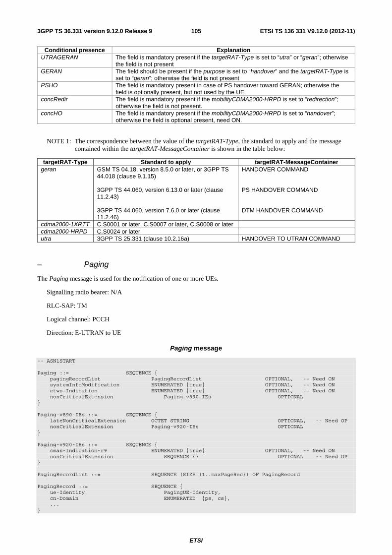
ETSI
ETSI TS 136 331 V9.12.0 (2012-11)1053GPP TS 36.331 version 9.12.0 Release 9
Conditional presence Explanation UTRAGERAN The field is mandatory present if the targetRAT-Type is set to “utra” or “geran”; otherwise
the field is not present GERAN The field should be present if the purpose is set to “handover” and the targetRAT-Type is
set to “geran”; otherwise the field is not present PSHO The field is mandatory present in case of PS handover toward GERAN; otherwise the
field is optionally present, but not used by the UE concRedir The field is mandatory present if the mobilityCDMA2000-HRPD is set to “redirection”;
otherwise the field is not present. concHO The field is mandatory present if the mobilityCDMA2000-HRPD is set to “handover”;
otherwise the field is optional present, need ON.
NOTE 1: The correspondence between the value of the targetRAT-Type, the standard to apply and the message contained within the targetRAT-MessageContainer is shown in the table below:
targetRAT-Type Standard to apply targetRAT-MessageContainer geran GSM TS 04.18, version 8.5.0 or later, or 3GPP TS
44.018 (clause 9.1.15) 3GPP TS 44.060, version 6.13.0 or later (clause 11.2.43) 3GPP TS 44.060, version 7.6.0 or later (clause 11.2.46)
HANDOVER COMMAND PS HANDOVER COMMAND DTM HANDOVER COMMAND
cdma2000-1XRTT C.S0001 or later, C.S0007 or later, C.S0008 or later cdma2000-HRPD C.S0024 or later utra 3GPP TS 25.331 (clause 10.2.16a) HANDOVER TO UTRAN COMMAND
– Paging
The Paging message is used for the notification of one or more UEs.
Signalling radio bearer: N/A
RLC-SAP: TM
Logical channel: PCCH
Direction: E-UTRAN to UE
Paging message
-- ASN1START Paging ::= SEQUENCE { pagingRecordList PagingRecordList OPTIONAL, -- Need ON systemInfoModification ENUMERATED {true} OPTIONAL, -- Need ON etws-Indication ENUMERATED {true} OPTIONAL, -- Need ON nonCriticalExtension Paging-v890-IEs OPTIONAL } Paging-v890-IEs ::= SEQUENCE { lateNonCriticalExtension OCTET STRING OPTIONAL, -- Need OP nonCriticalExtension Paging-v920-IEs OPTIONAL } Paging-v920-IEs ::= SEQUENCE { cmas-Indication-r9 ENUMERATED {true} OPTIONAL, -- Need ON nonCriticalExtension SEQUENCE {} OPTIONAL -- Need OP } PagingRecordList ::= SEQUENCE (SIZE (1..maxPageRec)) OF PagingRecord PagingRecord ::= SEQUENCE { ue-Identity PagingUE-Identity, cn-Domain ENUMERATED {ps, cs}, ... }

ETSI
ETSI TS 136 331 V9.12.0 (2012-11)1063GPP TS 36.331 version 9.12.0 Release 9
PagingUE-Identity ::= CHOICE { s-TMSI S-TMSI, imsi IMSI, ... } IMSI ::= SEQUENCE (SIZE (6..21)) OF IMSI-Digit IMSI-Digit ::= INTEGER (0..9) -- ASN1STOP
Paging field descriptions cn-Domain Indicates the origin of paging. ue-Identity Provides the NAS identity of the UE that is being paged. systemInfoModification If present: indication of a BCCH modification other than SIB10, SIB11 and SIB12. etws-Indication If present: indication of an ETWS primary notification and/ or ETWS secondary notification. cmas-Indication If present: indication of a CMAS notification. imsi The International Mobile Subscriber Identity, a globally unique permanent subscriber identity, see TS 23.003 [27]. The first element contains the first IMSI digit, the second element contains the second IMSI digit and so on.
– ProximityIndication
The ProximityIndication message is used to indicate that the UE is entering or leaving the proximity of one or more CSG member cell(s).
Signalling radio bearer: SRB1
RLC-SAP: AM
Logical channel: DCCH
Direction: UE to E-UTRAN
ProximityIndication message
-- ASN1START ProximityIndication-r9 ::= SEQUENCE { criticalExtensions CHOICE { c1 CHOICE { proximityIndication-r9 ProximityIndication-r9-IEs, spare3 NULL, spare2 NULL, spare1 NULL }, criticalExtensionsFuture SEQUENCE {} } } ProximityIndication-r9-IEs ::= SEQUENCE { type-r9 ENUMERATED {entering, leaving}, carrierFreq-r9 CHOICE { eutra-r9 ARFCN-ValueEUTRA, utra-r9 ARFCN-ValueUTRA, ... }, nonCriticalExtension ProximityIndication-v930-IEs OPTIONAL } ProximityIndication-v930-IEs ::= SEQUENCE { lateNonCriticalExtension OCTET STRING OPTIONAL, nonCriticalExtension SEQUENCE {} OPTIONAL }

ETSI
ETSI TS 136 331 V9.12.0 (2012-11)1073GPP TS 36.331 version 9.12.0 Release 9
-- ASN1STOP
ProximityIndication field descriptions type Used to indicate whether the UE is entering or leaving the proximity of CSG member cell(s). carrierFreq Indicates the RAT and frequency of the CSG member cell(s) for which the proximity indication is sent.
– RRCConnectionReconfiguration
The RRCConnectionReconfiguration message is the command to modify an RRC connection. It may convey information for measurement configuration, mobility control, radio resource configuration (including RBs, MAC main configuration and physical channel configuration) including any associated dedicated NAS information and security configuration.
Signalling radio bearer: SRB1
RLC-SAP: AM
Logical channel: DCCH
Direction: E-UTRAN to UE
RRCConnectionReconfiguration message
-- ASN1START RRCConnectionReconfiguration ::= SEQUENCE { rrc-TransactionIdentifier RRC-TransactionIdentifier, criticalExtensions CHOICE { c1 CHOICE{ rrcConnectionReconfiguration-r8 RRCConnectionReconfiguration-r8-IEs, spare7 NULL, spare6 NULL, spare5 NULL, spare4 NULL, spare3 NULL, spare2 NULL, spare1 NULL }, criticalExtensionsFuture SEQUENCE {} } } RRCConnectionReconfiguration-r8-IEs ::= SEQUENCE { measConfig MeasConfig OPTIONAL, -- Need ON mobilityControlInfo MobilityControlInfo OPTIONAL, -- Cond HO dedicatedInfoNASList SEQUENCE (SIZE(1..maxDRB)) OF DedicatedInfoNAS OPTIONAL, -- Cond nonHO radioResourceConfigDedicated RadioResourceConfigDedicated OPTIONAL, -- Cond HO-toEUTRA securityConfigHO SecurityConfigHO OPTIONAL, -- Cond HO nonCriticalExtension RRCConnectionReconfiguration-v890-IEs OPTIONAL } RRCConnectionReconfiguration-v890-IEs ::= SEQUENCE { lateNonCriticalExtension OCTET STRING OPTIONAL, -- Need OP nonCriticalExtension RRCConnectionReconfiguration-v920-IEs OPTIONAL } RRCConnectionReconfiguration-v920-IEs ::= SEQUENCE { otherConfig-r9 OtherConfig-r9 OPTIONAL, -- Need ON fullConfig-r9 ENUMERATED {true} OPTIONAL, -- Cond HO-Reestab nonCriticalExtension SEQUENCE {} OPTIONAL -- Need OP } SecurityConfigHO ::= SEQUENCE { handoverType CHOICE { intraLTE SEQUENCE { securityAlgorithmConfig SecurityAlgorithmConfig OPTIONAL, -- Cond fullConfig keyChangeIndicator BOOLEAN, nextHopChainingCount NextHopChainingCount },

ETSI
ETSI TS 136 331 V9.12.0 (2012-11)1083GPP TS 36.331 version 9.12.0 Release 9
interRAT SEQUENCE { securityAlgorithmConfig SecurityAlgorithmConfig, nas-SecurityParamToEUTRA OCTET STRING (SIZE(6)) } }, ... } -- ASN1STOP
RRCConnectionReconfiguration field descriptions dedicatedInfoNASList This field is used to transfer UE specific NAS layer information between the network and the UE. The RRC layer is transparent for each PDU in the list. nas-securityParamToEUTRA This field is used to transfer UE specific NAS layer information between the network and the UE. The RRC layer is transparent for this field, although it affects activation of AS- security after inter-RAT handover to E-UTRA. The content is defined in TS 24.301. keyChangeIndicator ‘true’ is used only in an intra-cell handover when a KeNB key is derived from a native KASME key taken into use through the successful NAS SMC, as described in TS 33.401 [32] for KeNB re-keying. ’false’ is used in an intra-LTE handover when the new KeNB key is obtained from the current KeNB key or from the NH as described in TS 33.401 [32]. nextHopChainingCount Parameter NCC: See TS 33.401 [32] fullConfig Indicates the full configuration option is applicable for the RRC Connection Reconfiguration message.
Conditional presence Explanation HO The field is mandatory present in case of handover within E-UTRA or to E-UTRA;
otherwise the field is not present. nonHO The field is not present in case of handover within E-UTRA or to E-UTRA; otherwise it is
optional present, need ON. HO-toEUTRA The field is mandatory present in case of handover to E-UTRA or for reconfigurations
when fullConfig is included; otherwise the field is optionally present, need ON. HO-Reestab This field is optionally present, need ON, in case of handover within E-UTRA or upon the
first reconfiguration after RRC connection re-establishment; otherwise the field is not present.
fullConfig This field is mandatory present for handover within E-UTRA when the fullConfig is included; otherwise it is optionally present, Need OP.
– RRCConnectionReconfigurationComplete
The RRCConnectionReconfigurationComplete message is used to confirm the successful completion of an RRC connection reconfiguration.
Signalling radio bearer: SRB1
RLC-SAP: AM
Logical channel: DCCH
Direction: UE to E-UTRAN
RRCConnectionReconfigurationComplete message
-- ASN1START RRCConnectionReconfigurationComplete ::= SEQUENCE { rrc-TransactionIdentifier RRC-TransactionIdentifier, criticalExtensions CHOICE { rrcConnectionReconfigurationComplete-r8 RRCConnectionReconfigurationComplete-r8-IEs, criticalExtensionsFuture SEQUENCE {}

ETSI
ETSI TS 136 331 V9.12.0 (2012-11)1093GPP TS 36.331 version 9.12.0 Release 9
} } RRCConnectionReconfigurationComplete-r8-IEs ::= SEQUENCE { nonCriticalExtension RRCConnectionReconfigurationComplete-v8a0-IEs OPTIONAL } RRCConnectionReconfigurationComplete-v8a0-IEs ::= SEQUENCE { lateNonCriticalExtension OCTET STRING OPTIONAL, nonCriticalExtension SEQUENCE {} OPTIONAL } -- ASN1STOP
– RRCConnectionReestablishment
The RRCConnectionReestablishment message is used to resolve contention and to re-establish SRB1.
Signalling radio bearer: SRB0
RLC-SAP: TM
Logical channel: CCCH
Direction: E-UTRAN to UE
RRCConnectionReestablishment message
-- ASN1START RRCConnectionReestablishment ::= SEQUENCE { rrc-TransactionIdentifier RRC-TransactionIdentifier, criticalExtensions CHOICE { c1 CHOICE{ rrcConnectionReestablishment-r8 RRCConnectionReestablishment-r8-IEs, spare7 NULL, spare6 NULL, spare5 NULL, spare4 NULL, spare3 NULL, spare2 NULL, spare1 NULL }, criticalExtensionsFuture SEQUENCE {} } } RRCConnectionReestablishment-r8-IEs ::= SEQUENCE { radioResourceConfigDedicated RadioResourceConfigDedicated, nextHopChainingCount NextHopChainingCount, nonCriticalExtension RRCConnectionReestablishment-v8a0-IEs OPTIONAL } RRCConnectionReestablishment-v8a0-IEs ::= SEQUENCE { lateNonCriticalExtension OCTET STRING OPTIONAL, -- Need OP nonCriticalExtension SEQUENCE {} OPTIONAL -- Need OP } -- ASN1STOP
– RRCConnectionReestablishmentComplete
The RRCConnectionReestablishmentComplete message is used to confirm the successful completion of an RRC connection reestablishment.

ETSI
ETSI TS 136 331 V9.12.0 (2012-11)1103GPP TS 36.331 version 9.12.0 Release 9
Signalling radio bearer: SRB1
RLC-SAP: AM
Logical channel: DCCH
Direction: UE to E-UTRAN
RRCConnectionReestablishmentComplete message
-- ASN1START RRCConnectionReestablishmentComplete ::= SEQUENCE { rrc-TransactionIdentifier RRC-TransactionIdentifier, criticalExtensions CHOICE { rrcConnectionReestablishmentComplete-r8 RRCConnectionReestablishmentComplete-r8-IEs, criticalExtensionsFuture SEQUENCE {} } } RRCConnectionReestablishmentComplete-r8-IEs ::= SEQUENCE { nonCriticalExtension RRCConnectionReestablishmentComplete-v920-IEs OPTIONAL } RRCConnectionReestablishmentComplete-v920-IEs ::= SEQUENCE { rlf-InfoAvailable-r9 ENUMERATED {true} OPTIONAL, nonCriticalExtension RRCConnectionReestablishmentComplete-v8a0-IEs OPTIONAL } RRCConnectionReestablishmentComplete-v8a0-IEs ::= SEQUENCE { lateNonCriticalExtension OCTET STRING OPTIONAL, nonCriticalExtension SEQUENCE {} OPTIONAL } -- ASN1STOP
RRCConnectionReestablishmentComplete field descriptions rlf-InfoAvailable This field is used to indicate the availability of radio link failure related measurements
– RRCConnectionReestablishmentReject
The RRCConnectionReestablishmentReject message is used to indicate the rejection of an RRC connection reestablishment request.
Signalling radio bearer: SRB0
RLC-SAP: TM
Logical channel: CCCH
Direction: E-UTRAN to UE
RRCConnectionReestablishmentReject message
-- ASN1START RRCConnectionReestablishmentReject ::= SEQUENCE { criticalExtensions CHOICE { rrcConnectionReestablishmentReject-r8 RRCConnectionReestablishmentReject-r8-IEs, criticalExtensionsFuture SEQUENCE {} } } RRCConnectionReestablishmentReject-r8-IEs ::= SEQUENCE {

ETSI
ETSI TS 136 331 V9.12.0 (2012-11)1113GPP TS 36.331 version 9.12.0 Release 9
nonCriticalExtension RRCConnectionReestablishmentReject-v8a0-IEs OPTIONAL } RRCConnectionReestablishmentReject-v8a0-IEs ::= SEQUENCE { lateNonCriticalExtension OCTET STRING OPTIONAL, -- Need OP nonCriticalExtension SEQUENCE {} OPTIONAL -- Need OP } -- ASN1STOP
– RRCConnectionReestablishmentRequest
The RRCConnectionReestablishmentRequest message is used to request the reestablishment of an RRC connection.
Signalling radio bearer: SRB0
RLC-SAP: TM
Logical channel: CCCH
Direction: UE to E-UTRAN
RRCConnectionReestablishmentRequest message
-- ASN1START RRCConnectionReestablishmentRequest ::= SEQUENCE { criticalExtensions CHOICE { rrcConnectionReestablishmentRequest-r8 RRCConnectionReestablishmentRequest-r8-IEs, criticalExtensionsFuture SEQUENCE {} } } RRCConnectionReestablishmentRequest-r8-IEs ::= SEQUENCE { ue-Identity ReestabUE-Identity, reestablishmentCause ReestablishmentCause, spare BIT STRING (SIZE (2)) } ReestabUE-Identity ::= SEQUENCE { c-RNTI C-RNTI, physCellId PhysCellId, shortMAC-I ShortMAC-I } ReestablishmentCause ::= ENUMERATED { reconfigurationFailure, handoverFailure, otherFailure, spare1} -- ASN1STOP
RRCConnectionReestablishmentRequest field descriptions ue-Identity UE identity included to retrieve UE context and to facilitate contention resolution by lower layers. reestablishmentCause Indicates the failure cause that triggered the re-establishment procedure. physCellId The Physical Cell Identity of the cell the UE was connected to prior to the failure.
– RRCConnectionReject
The RRCConnectionReject message is used to reject the RRC connection establishment.
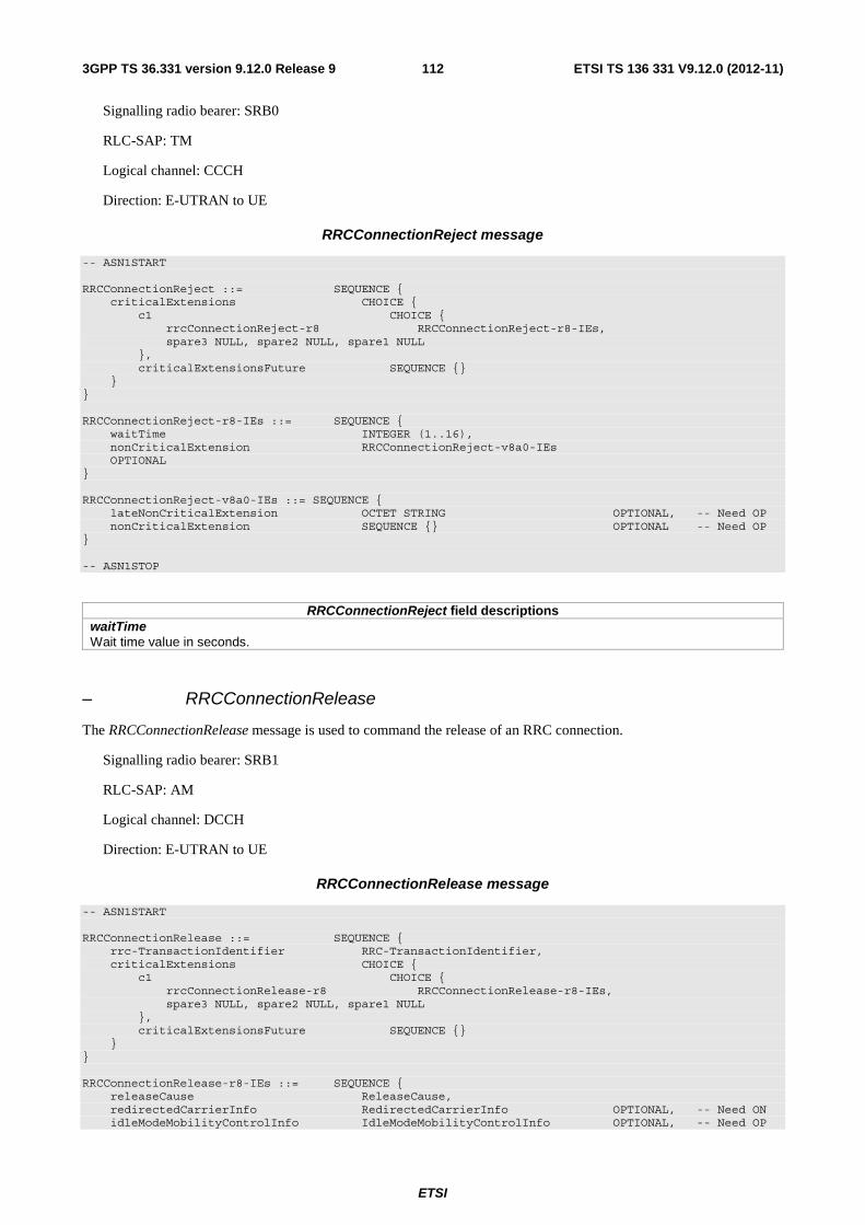
ETSI
ETSI TS 136 331 V9.12.0 (2012-11)1123GPP TS 36.331 version 9.12.0 Release 9
Signalling radio bearer: SRB0
RLC-SAP: TM
Logical channel: CCCH
Direction: E-UTRAN to UE
RRCConnectionReject message
-- ASN1START RRCConnectionReject ::= SEQUENCE { criticalExtensions CHOICE { c1 CHOICE { rrcConnectionReject-r8 RRCConnectionReject-r8-IEs, spare3 NULL, spare2 NULL, spare1 NULL }, criticalExtensionsFuture SEQUENCE {} } } RRCConnectionReject-r8-IEs ::= SEQUENCE { waitTime INTEGER (1..16), nonCriticalExtension RRCConnectionReject-v8a0-IEs OPTIONAL } RRCConnectionReject-v8a0-IEs ::= SEQUENCE { lateNonCriticalExtension OCTET STRING OPTIONAL, -- Need OP nonCriticalExtension SEQUENCE {} OPTIONAL -- Need OP } -- ASN1STOP
RRCConnectionReject field descriptions waitTime Wait time value in seconds.
– RRCConnectionRelease
The RRCConnectionRelease message is used to command the release of an RRC connection.
Signalling radio bearer: SRB1
RLC-SAP: AM
Logical channel: DCCH
Direction: E-UTRAN to UE
RRCConnectionRelease message
-- ASN1START RRCConnectionRelease ::= SEQUENCE { rrc-TransactionIdentifier RRC-TransactionIdentifier, criticalExtensions CHOICE { c1 CHOICE { rrcConnectionRelease-r8 RRCConnectionRelease-r8-IEs, spare3 NULL, spare2 NULL, spare1 NULL }, criticalExtensionsFuture SEQUENCE {} } } RRCConnectionRelease-r8-IEs ::= SEQUENCE { releaseCause ReleaseCause, redirectedCarrierInfo RedirectedCarrierInfo OPTIONAL, -- Need ON idleModeMobilityControlInfo IdleModeMobilityControlInfo OPTIONAL, -- Need OP

ETSI
ETSI TS 136 331 V9.12.0 (2012-11)1133GPP TS 36.331 version 9.12.0 Release 9
nonCriticalExtension RRCConnectionRelease-v890-IEs OPTIONAL } RRCConnectionRelease-v890-IEs ::= SEQUENCE { lateNonCriticalExtension OCTET STRING OPTIONAL, -- Need OP nonCriticalExtension RRCConnectionRelease-v920-IEs OPTIONAL } RRCConnectionRelease-v920-IEs ::= SEQUENCE { cellInfoList-r9 CHOICE { geran-r9 CellInfoListGERAN-r9, utra-FDD-r9 CellInfoListUTRA-FDD-r9, utra-TDD-r9 CellInfoListUTRA-TDD-r9, ... } OPTIONAL, -- Cond Redirection nonCriticalExtension SEQUENCE {} OPTIONAL -- Need OP } ReleaseCause ::= ENUMERATED {loadBalancingTAUrequired, other,spare2,spare1} RedirectedCarrierInfo ::= CHOICE { eutra ARFCN-ValueEUTRA, geran CarrierFreqsGERAN, utra-FDD ARFCN-ValueUTRA, utra-TDD ARFCN-ValueUTRA, cdma2000-HRPD CarrierFreqCDMA2000, cdma2000-1xRTT CarrierFreqCDMA2000, ... } IdleModeMobilityControlInfo ::= SEQUENCE { freqPriorityListEUTRA FreqPriorityListEUTRA OPTIONAL, -- Need ON freqPriorityListGERAN FreqsPriorityListGERAN OPTIONAL, -- Need ON freqPriorityListUTRA-FDD FreqPriorityListUTRA-FDD OPTIONAL, -- Need ON freqPriorityListUTRA-TDD FreqPriorityListUTRA-TDD OPTIONAL, -- Need ON bandClassPriorityListHRPD BandClassPriorityListHRPD OPTIONAL, -- Need ON bandClassPriorityList1XRTT BandClassPriorityList1XRTT OPTIONAL, -- Need ON t320 ENUMERATED { min5, min10, min20, min30, min60, min120, min180, spare1} OPTIONAL, -- Need OR ... } FreqPriorityListEUTRA ::= SEQUENCE (SIZE (1..maxFreq)) OF FreqPriorityEUTRA FreqPriorityEUTRA ::= SEQUENCE { carrierFreq ARFCN-ValueEUTRA, cellReselectionPriority CellReselectionPriority } FreqsPriorityListGERAN ::= SEQUENCE (SIZE (1..maxGNFG)) OF FreqsPriorityGERAN FreqsPriorityGERAN ::= SEQUENCE { carrierFreqs CarrierFreqsGERAN, cellReselectionPriority CellReselectionPriority } FreqPriorityListUTRA-FDD ::= SEQUENCE (SIZE (1..maxUTRA-FDD-Carrier)) OF FreqPriorityUTRA-FDD FreqPriorityUTRA-FDD ::= SEQUENCE { carrierFreq ARFCN-ValueUTRA, cellReselectionPriority CellReselectionPriority } FreqPriorityListUTRA-TDD ::= SEQUENCE (SIZE (1..maxUTRA-TDD-Carrier)) OF FreqPriorityUTRA-TDD FreqPriorityUTRA-TDD ::= SEQUENCE { carrierFreq ARFCN-ValueUTRA, cellReselectionPriority CellReselectionPriority } BandClassPriorityListHRPD ::= SEQUENCE (SIZE (1..maxCDMA-BandClass)) OF BandClassPriorityHRPD BandClassPriorityHRPD ::= SEQUENCE { bandClass BandclassCDMA2000, cellReselectionPriority CellReselectionPriority }

ETSI
ETSI TS 136 331 V9.12.0 (2012-11)1143GPP TS 36.331 version 9.12.0 Release 9
BandClassPriorityList1XRTT ::= SEQUENCE (SIZE (1..maxCDMA-BandClass)) OF BandClassPriority1XRTT BandClassPriority1XRTT ::= SEQUENCE { bandClass BandclassCDMA2000, cellReselectionPriority CellReselectionPriority } CellInfoListGERAN-r9 ::= SEQUENCE (SIZE (1..maxCellInfoGERAN-r9)) OF CellInfoGERAN-r9 CellInfoGERAN-r9 ::= SEQUENCE { physCellId-r9 PhysCellIdGERAN, carrierFreq-r9 CarrierFreqGERAN, systemInformation-r9 SystemInfoListGERAN } CellInfoListUTRA-FDD-r9 ::= SEQUENCE (SIZE (1..maxCellInfoUTRA-r9)) OF CellInfoUTRA-FDD-r9 CellInfoUTRA-FDD-r9 ::= SEQUENCE { physCellId-r9 PhysCellIdUTRA-FDD, utra-BCCH-Container-r9 OCTET STRING } CellInfoListUTRA-TDD-r9 ::= SEQUENCE (SIZE (1..maxCellInfoUTRA-r9)) OF CellInfoUTRA-TDD-r9 CellInfoUTRA-TDD-r9 ::= SEQUENCE { physCellId-r9 PhysCellIdUTRA-TDD, utra-BCCH-Container-r9 OCTET STRING } -- ASN1STOP
RRCConnectionRelease field descriptions releaseCause The releaseCause is used to indicate the reason for releasing the RRC Connection. redirectedCarrierInfo The redirectedCarrierInfo indicates a carrier frequency (downlink for FDD) and is used to redirect the UE to an E-UTRA or an inter-RAT carrier frequency, by means of the cell selection upon leaving RRC_CONNECTED as specified in TS 36.304 [4]. idleModeMobilityControlInfo Provides dedicated cell reselection priorities. Used for cell reselection as specified in TS 36.304 [4]. freqPriorityListX Provides a cell reselection priority for each frequency, by means of separate lists for each RAT (including E-UTRA). carrierFreq or bandClass The carrier frequency (UTRA and E-UTRA) and band class (HRPD and 1xRTT) for which the associated cellReselectionPriority is applied. t320 Timer T320 as described in section 7.3. Value minN corresponds to N minutes. carrierFreqs The list of GERAN carrier frequencies organised into one group of GERAN carrier frequencies. systemInformation Container for system information of the GERAN cell i.e. one or more System Information (SI) messages as defined in TS 44.018 [45, table 9.1.1]. cellInfoList Used to provide system information of one or more cells on the redirected inter-RAT carrier frequency. The system information can be used if, upon redirection, the UE selects an inter-RAT cell indicated by the physCellId and carrierFreq (GERAN) or by the physCellId (other RATs). The choice shall match the redirectedCarrierInfo. utra-BCCH-Container Contains System Information Container message as defined in TS 25.331 [19].
Conditional presence Explanation Redirection The field is optionally present, need ON, if the redirectedCarrierInfo is included and set to
‘geran’, ‘utra-FDD’ or ‘utra-TDD’; otherwise the field is not present.
– RRCConnectionRequest
The RRCConnectionRequest message is used to request the establishment of an RRC connection.
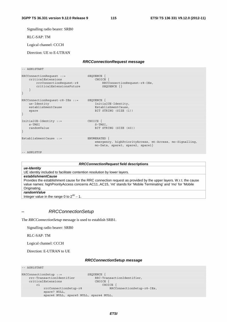
ETSI
ETSI TS 136 331 V9.12.0 (2012-11)1153GPP TS 36.331 version 9.12.0 Release 9
Signalling radio bearer: SRB0
RLC-SAP: TM
Logical channel: CCCH
Direction: UE to E-UTRAN
RRCConnectionRequest message
-- ASN1START RRCConnectionRequest ::= SEQUENCE { criticalExtensions CHOICE { rrcConnectionRequest-r8 RRCConnectionRequest-r8-IEs, criticalExtensionsFuture SEQUENCE {} } } RRCConnectionRequest-r8-IEs ::= SEQUENCE { ue-Identity InitialUE-Identity, establishmentCause EstablishmentCause, spare BIT STRING (SIZE (1)) } InitialUE-Identity ::= CHOICE { s-TMSI S-TMSI, randomValue BIT STRING (SIZE (40)) } EstablishmentCause ::= ENUMERATED { emergency, highPriorityAccess, mt-Access, mo-Signalling, mo-Data, spare3, spare2, spare1} -- ASN1STOP
RRCConnectionRequest field descriptions ue-Identity UE identity included to facilitate contention resolution by lower layers. establishmentCause Provides the establishment cause for the RRC connection request as provided by the upper layers. W.r.t. the cause value names: highPriorityAccess concerns AC11..AC15, ‘mt’ stands for ‘Mobile Terminating’ and ‘mo’ for ‘Mobile Originating. randomValue Integer value in the range 0 to 240 − 1.
– RRCConnectionSetup
The RRCConnectionSetup message is used to establish SRB1.
Signalling radio bearer: SRB0
RLC-SAP: TM
Logical channel: CCCH
Direction: E-UTRAN to UE
RRCConnectionSetup message
-- ASN1START RRCConnectionSetup ::= SEQUENCE { rrc-TransactionIdentifier RRC-TransactionIdentifier, criticalExtensions CHOICE { c1 CHOICE { rrcConnectionSetup-r8 RRCConnectionSetup-r8-IEs, spare7 NULL, spare6 NULL, spare5 NULL, spare4 NULL,

ETSI
ETSI TS 136 331 V9.12.0 (2012-11)1163GPP TS 36.331 version 9.12.0 Release 9
spare3 NULL, spare2 NULL, spare1 NULL }, criticalExtensionsFuture SEQUENCE {} } } RRCConnectionSetup-r8-IEs ::= SEQUENCE { radioResourceConfigDedicated RadioResourceConfigDedicated, nonCriticalExtension RRCConnectionSetup-v8a0-IEs OPTIONAL } RRCConnectionSetup-v8a0-IEs ::= SEQUENCE { lateNonCriticalExtension OCTET STRING OPTIONAL, -- Need OP nonCriticalExtension SEQUENCE {} OPTIONAL -- Need OP } -- ASN1STOP
– RRCConnectionSetupComplete
The RRCConnectionSetupComplete message is used to confirm the successful completion of an RRC connection establishment.
Signalling radio bearer: SRB1
RLC-SAP: AM
Logical channel: DCCH
Direction: UE to E-UTRAN
RRCConnectionSetupComplete message
-- ASN1START RRCConnectionSetupComplete ::= SEQUENCE { rrc-TransactionIdentifier RRC-TransactionIdentifier, criticalExtensions CHOICE { c1 CHOICE{ rrcConnectionSetupComplete-r8 RRCConnectionSetupComplete-r8-IEs, spare3 NULL, spare2 NULL, spare1 NULL }, criticalExtensionsFuture SEQUENCE {} } } RRCConnectionSetupComplete-r8-IEs ::= SEQUENCE { selectedPLMN-Identity INTEGER (1..6), registeredMME RegisteredMME OPTIONAL, dedicatedInfoNAS DedicatedInfoNAS, nonCriticalExtension RRCConnectionSetupComplete-v8a0-IEs OPTIONAL } RRCConnectionSetupComplete-v8a0-IEs ::= SEQUENCE { lateNonCriticalExtension OCTET STRING OPTIONAL, nonCriticalExtension SEQUENCE {} OPTIONAL } RegisteredMME ::= SEQUENCE { plmn-Identity PLMN-Identity OPTIONAL, mmegi BIT STRING (SIZE (16)), mmec MMEC } -- ASN1STOP

ETSI
ETSI TS 136 331 V9.12.0 (2012-11)1173GPP TS 36.331 version 9.12.0 Release 9
RRCConnectionSetupComplete field descriptions selectedPLMN-Identity Index of the PLMN selected by the UE from the plmn-IdentityList included in SIB1. 1 if the 1st PLMN is selected from the plmn-IdentityList included in SIB1, 2 if the 2nd PLMN is selected from the plmn-IdentityList included in SIB1 and so on. registeredMME This field is used to transfer the GUMMEI of the MME where the UE is registered, as provided by upper layers. mmegi Provides the Group Identity of the registered MME within the PLMN, as provided by upper layers, see TS 23.003 [27].
– SecurityModeCommand
The SecurityModeCommand message is used to command the activation of AS security.
Signalling radio bearer: SRB1
RLC-SAP: AM
Logical channel: DCCH
Direction: E-UTRAN to UE
SecurityModeCommand message
-- ASN1START SecurityModeCommand ::= SEQUENCE { rrc-TransactionIdentifier RRC-TransactionIdentifier, criticalExtensions CHOICE { c1 CHOICE{ securityModeCommand-r8 SecurityModeCommand-r8-IEs, spare3 NULL, spare2 NULL, spare1 NULL }, criticalExtensionsFuture SEQUENCE {} } } SecurityModeCommand-r8-IEs ::= SEQUENCE { securityConfigSMC SecurityConfigSMC, nonCriticalExtension SecurityModeCommand-v8a0-IEs OPTIONAL } SecurityModeCommand-v8a0-IEs ::= SEQUENCE { lateNonCriticalExtension OCTET STRING OPTIONAL, -- Need OP nonCriticalExtension SEQUENCE {} OPTIONAL -- Need OP } SecurityConfigSMC ::= SEQUENCE { securityAlgorithmConfig SecurityAlgorithmConfig, ... } -- ASN1STOP
– SecurityModeComplete
The SecurityModeComplete message is used to confirm the successful completion of a security mode command.

ETSI
ETSI TS 136 331 V9.12.0 (2012-11)1183GPP TS 36.331 version 9.12.0 Release 9
Signalling radio bearer: SRB1
RLC-SAP: AM
Logical channel: DCCH
Direction: UE to E-UTRAN
SecurityModeComplete message
-- ASN1START SecurityModeComplete ::= SEQUENCE { rrc-TransactionIdentifier RRC-TransactionIdentifier, criticalExtensions CHOICE { securityModeComplete-r8 SecurityModeComplete-r8-IEs, criticalExtensionsFuture SEQUENCE {} } } SecurityModeComplete-r8-IEs ::= SEQUENCE { nonCriticalExtension SecurityModeComplete-v8a0-IEs OPTIONAL } SecurityModeComplete-v8a0-IEs ::= SEQUENCE { lateNonCriticalExtension OCTET STRING OPTIONAL, nonCriticalExtension SEQUENCE {} OPTIONAL } -- ASN1STOP
– SecurityModeFailure
The SecurityModeFailure message is used to indicate an unsuccessful completion of a security mode command.
Signalling radio bearer: SRB1
RLC-SAP: AM
Logical channel: DCCH
Direction: UE to E-UTRAN
SecurityModeFailure message
-- ASN1START SecurityModeFailure ::= SEQUENCE { rrc-TransactionIdentifier RRC-TransactionIdentifier, criticalExtensions CHOICE { securityModeFailure-r8 SecurityModeFailure-r8-IEs, criticalExtensionsFuture SEQUENCE {} } } SecurityModeFailure-r8-IEs ::= SEQUENCE { nonCriticalExtension SecurityModeFailure-v8a0-IEs OPTIONAL } SecurityModeFailure-v8a0-IEs ::= SEQUENCE { lateNonCriticalExtension OCTET STRING OPTIONAL, nonCriticalExtension SEQUENCE {} OPTIONAL } -- ASN1STOP

ETSI
ETSI TS 136 331 V9.12.0 (2012-11)1193GPP TS 36.331 version 9.12.0 Release 9
– SystemInformation
The SystemInformation message is used to convey one or more System Information Blocks. All the SIBs included are transmitted with the same periodicity.
Signalling radio bearer: N/A
RLC-SAP: TM
Logical channel: BCCH
Direction: E-UTRAN to UE
SystemInformation message
-- ASN1START SystemInformation ::= SEQUENCE { criticalExtensions CHOICE { systemInformation-r8 SystemInformation-r8-IEs, criticalExtensionsFuture SEQUENCE {} } } SystemInformation-r8-IEs ::= SEQUENCE { sib-TypeAndInfo SEQUENCE (SIZE (1..maxSIB)) OF CHOICE { sib2 SystemInformationBlockType2, sib3 SystemInformationBlockType3, sib4 SystemInformationBlockType4, sib5 SystemInformationBlockType5, sib6 SystemInformationBlockType6, sib7 SystemInformationBlockType7, sib8 SystemInformationBlockType8, sib9 SystemInformationBlockType9, sib10 SystemInformationBlockType10, sib11 SystemInformationBlockType11, ..., sib12-v920 SystemInformationBlockType12-r9, sib13-v920 SystemInformationBlockType13-r9 }, nonCriticalExtension SystemInformation-v8a0-IEs OPTIONAL } SystemInformation-v8a0-IEs ::= SEQUENCE { lateNonCriticalExtension OCTET STRING OPTIONAL, -- Need OP nonCriticalExtension SEQUENCE {} OPTIONAL -- Need OP } -- ASN1STOP
– SystemInformationBlockType1
SystemInformationBlockType1 contains information relevant when evaluating if a UE is allowed to access a cell and defines the scheduling of other system information.
Signalling radio bearer: N/A
RLC-SAP: TM
Logical channel: BCCH
Direction: E-UTRAN to UE
SystemInformationBlockType1 message
-- ASN1START SystemInformationBlockType1 ::= SEQUENCE { cellAccessRelatedInfo SEQUENCE { plmn-IdentityList PLMN-IdentityList, trackingAreaCode TrackingAreaCode, cellIdentity CellIdentity,

ETSI
ETSI TS 136 331 V9.12.0 (2012-11)1203GPP TS 36.331 version 9.12.0 Release 9
cellBarred ENUMERATED {barred, notBarred}, intraFreqReselection ENUMERATED {allowed, notAllowed}, csg-Indication BOOLEAN, csg-Identity CSG-Identity OPTIONAL -- Need OR }, cellSelectionInfo SEQUENCE { q-RxLevMin Q-RxLevMin, q-RxLevMinOffset INTEGER (1..8) OPTIONAL -- Need OP }, p-Max P-Max OPTIONAL, -- Need OP freqBandIndicator FreqBandIndicator, schedulingInfoList SchedulingInfoList, tdd-Config TDD-Config OPTIONAL, -- Cond TDD si-WindowLength ENUMERATED { ms1, ms2, ms5, ms10, ms15, ms20, ms40}, systemInfoValueTag INTEGER (0..31), nonCriticalExtension SystemInformationBlockType1-v890-IEs OPTIONAL } SystemInformationBlockType1-v890-IEs::= SEQUENCE { lateNonCriticalExtension OCTET STRING (CONTAINING SystemInformationBlockType1-v8h0-IEs) OPTIONAL, -- Need OP nonCriticalExtension SystemInformationBlockType1-v920-IEs OPTIONAL } SystemInformationBlockType1-v8h0-IEs ::= SEQUENCE { multiBandInfoList MultiBandInfoList OPTIONAL, -- Need OR nonCriticalExtension SEQUENCE {} OPTIONAL -- Need OP } SystemInformationBlockType1-v920-IEs ::= SEQUENCE { ims-EmergencySupport-r9 ENUMERATED {true} OPTIONAL, -- Need OR cellSelectionInfo-v920 CellSelectionInfo-v920 OPTIONAL, -- Cond RSRQ nonCriticalExtension SEQUENCE {} OPTIONAL -- Need OP } PLMN-IdentityList ::= SEQUENCE (SIZE (1..6)) OF PLMN-IdentityInfo PLMN-IdentityInfo ::= SEQUENCE { plmn-Identity PLMN-Identity, cellReservedForOperatorUse ENUMERATED {reserved, notReserved} } SchedulingInfoList ::= SEQUENCE (SIZE (1..maxSI-Message)) OF SchedulingInfo SchedulingInfo ::= SEQUENCE { si-Periodicity ENUMERATED { rf8, rf16, rf32, rf64, rf128, rf256, rf512}, sib-MappingInfo SIB-MappingInfo } SIB-MappingInfo ::= SEQUENCE (SIZE (0..maxSIB-1)) OF SIB-Type SIB-Type ::= ENUMERATED { sibType3, sibType4, sibType5, sibType6, sibType7, sibType8, sibType9, sibType10, sibType11, sibType12-v920, sibType13-v920, spare5, spare4, spare3, spare2, spare1, ...} CellSelectionInfo-v920 ::= SEQUENCE { q-QualMin-r9 Q-QualMin-r9, q-QualMinOffset-r9 INTEGER (1..8) OPTIONAL -- Need OP } -- ASN1STOP

ETSI
ETSI TS 136 331 V9.12.0 (2012-11)1213GPP TS 36.331 version 9.12.0 Release 9
SystemInformationBlockType1 field descriptions multiBandInfoList A list of additional frequency band indicators, including the frequency band indicated by freqBandIndicator, as defined in TS 36.101 [42, table 5.5-1] that the cell belongs to. If there are multiple bands supported by the UE, the UE shall apply the first listed band which it supports. plmn-IdentityList List of PLMN identities. The first listed PLMN-Identity is the primary PLMN. cellReservedForOperatorUse As defined in TS 36.304 [4]. trackingAreaCode A trackingAreaCode that is common for all the PLMNs listed. cellBarred ‘barred’ means the cell is barred, as defined in TS 36.304 [4]. intraFreqReselection Used to control cell reselection to intra-frequency cells when the highest ranked cell is barred, or treated as barred by the UE, as specified in TS 36.304 [4]. csg-Indication If set to TRUE the UE is only allowed to access the cell if it is a CSG member cell or if selected during manual CSG selection, see TS 36.304 [4]. q-RxLevMinOffset Parameter Qrxlevminoffset in TS 36.304 [4]. Actual value Qrxlevminoffset = IE value * 2 [dB]. If absent, the UE applies the (default) value of 0 dB for Qrxlevminoffset. Affects the minimum required Rx level in the cell. p-Max Value applicable for the cell. If absent the UE applies the maximum power according to the UE capability. si-Periodicity Periodicity of the SI-message in radio frames, such that rf8 denotes 8 radio frames, rf16 denotes 16 radio frames, and so on. sib-MappingInfo List of the SIBs mapped to this SystemInformation message.There is no mapping information of SIB2; it is always present in the first SystemInformation message listed in the schedulingInfoList list. si-WindowLength Common SI scheduling window for all SIs. Unit in milliseconds, where ms1 denotes 1 millisecond, ms2 denotes 2 milliseconds and so on. systemInfoValueTag Common for all SIBs other than MIB, SIB1, SIB10, SIB11 and SIB12. Change of MIB and SIB1 is detected by acquisition of the corresponding message. csg-Identity Identity of the Closed Subscriber Group the cell belongs to. The field is present in a CSG cell. ims-EmergencySupport Indicates whether the cell supports IMS emergency bearer services for UEs in limited service mode. If absent, IMS emergency call is not supported by the network in the cell for UEs in limited service mode. q-QualMin Parameter “Qqualmin” in TS 36.304 [4]. If cellSelectionInfo-v920 is not present, the UE applies the (default) value of negative infinity for Qqualmin. q-QualMinOffset Parameter “Qqualminoffset” in TS 36.304 [4]. Actual value Qqualminoffset = IE value [dB]. If cellSelectionInfo-v920 is not present or the field is not present, the UE applies the (default) value of 0 dB for Qqualminoffset. Affects the minimum required quality level in the cell.
Conditional presence Explanation TDD This field is mandatory present for TDD; it is not present for FDD and the UE shall delete
any existing value for this field. RSRQ The field is mandatory present if SIB3 is being broadcasted and threshServingLowQ is
present in SIB3; otherwise optionally present, Need OP.
– UECapabilityEnquiry
The UECapabilityEnquiry message is used to request the transfer of UE radio access capabilities for E-UTRA as well as for other RATs.
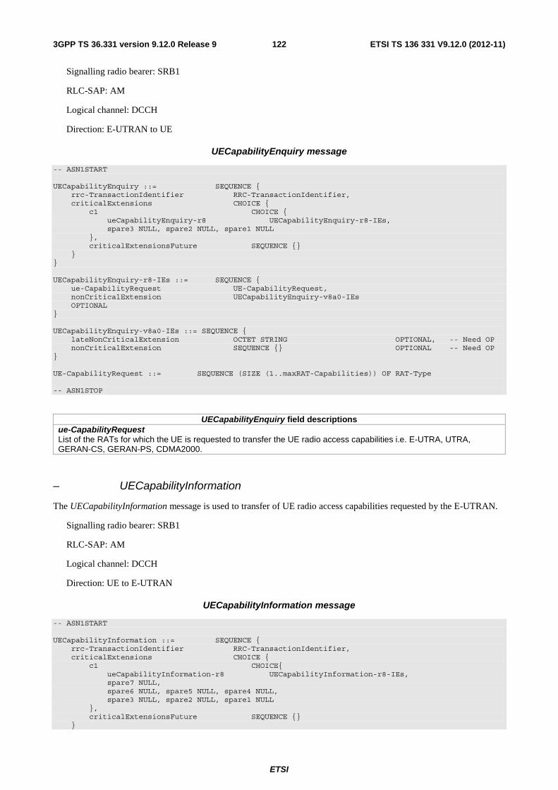
ETSI
ETSI TS 136 331 V9.12.0 (2012-11)1223GPP TS 36.331 version 9.12.0 Release 9
Signalling radio bearer: SRB1
RLC-SAP: AM
Logical channel: DCCH
Direction: E-UTRAN to UE
UECapabilityEnquiry message
-- ASN1START UECapabilityEnquiry ::= SEQUENCE { rrc-TransactionIdentifier RRC-TransactionIdentifier, criticalExtensions CHOICE { c1 CHOICE { ueCapabilityEnquiry-r8 UECapabilityEnquiry-r8-IEs, spare3 NULL, spare2 NULL, spare1 NULL }, criticalExtensionsFuture SEQUENCE {} } } UECapabilityEnquiry-r8-IEs ::= SEQUENCE { ue-CapabilityRequest UE-CapabilityRequest, nonCriticalExtension UECapabilityEnquiry-v8a0-IEs OPTIONAL } UECapabilityEnquiry-v8a0-IEs ::= SEQUENCE { lateNonCriticalExtension OCTET STRING OPTIONAL, -- Need OP nonCriticalExtension SEQUENCE {} OPTIONAL -- Need OP } UE-CapabilityRequest ::= SEQUENCE (SIZE (1..maxRAT-Capabilities)) OF RAT-Type -- ASN1STOP
UECapabilityEnquiry field descriptions ue-CapabilityRequest List of the RATs for which the UE is requested to transfer the UE radio access capabilities i.e. E-UTRA, UTRA, GERAN-CS, GERAN-PS, CDMA2000.
– UECapabilityInformation
The UECapabilityInformation message is used to transfer of UE radio access capabilities requested by the E-UTRAN.
Signalling radio bearer: SRB1
RLC-SAP: AM
Logical channel: DCCH
Direction: UE to E-UTRAN
UECapabilityInformation message
-- ASN1START UECapabilityInformation ::= SEQUENCE { rrc-TransactionIdentifier RRC-TransactionIdentifier, criticalExtensions CHOICE { c1 CHOICE{ ueCapabilityInformation-r8 UECapabilityInformation-r8-IEs, spare7 NULL, spare6 NULL, spare5 NULL, spare4 NULL, spare3 NULL, spare2 NULL, spare1 NULL }, criticalExtensionsFuture SEQUENCE {} }

ETSI
ETSI TS 136 331 V9.12.0 (2012-11)1233GPP TS 36.331 version 9.12.0 Release 9
} UECapabilityInformation-r8-IEs ::= SEQUENCE { ue-CapabilityRAT-ContainerList UE-CapabilityRAT-ContainerList, nonCriticalExtension UECapabilityInformation-v8a0-IEs OPTIONAL } UECapabilityInformation-v8a0-IEs ::= SEQUENCE { lateNonCriticalExtension OCTET STRING OPTIONAL, nonCriticalExtension SEQUENCE {} OPTIONAL } -- ASN1STOP
– UEInformationRequest
The UEInformationRequest is the command used by E-UTRAN to retrieve information from the UE.
Signalling radio bearer: SRB1
RLC-SAP: AM
Logical channel: DCCH
Direction: E-UTRAN to UE
UEInformationRequest message
-- ASN1START UEInformationRequest-r9 ::= SEQUENCE { rrc-TransactionIdentifier RRC-TransactionIdentifier, criticalExtensions CHOICE { c1 CHOICE { ueInformationRequest-r9 UEInformationRequest-r9-IEs, spare3 NULL, spare2 NULL, spare1 NULL }, criticalExtensionsFuture SEQUENCE {} } } UEInformationRequest-r9-IEs ::= SEQUENCE { rach-ReportReq-r9 BOOLEAN, rlf-ReportReq-r9 BOOLEAN, nonCriticalExtension UEInformationRequest-v930-IEs OPTIONAL } UEInformationRequest-v930-IEs ::= SEQUENCE { lateNonCriticalExtension OCTET STRING OPTIONAL, -- Need OP nonCriticalExtension SEQUENCE {} OPTIONAL -- Need OP } -- ASN1STOP
UEInformationRequest field descriptions rach-ReportReq This field is used to indicate whether the UE shall report information about the random access procedure.
– UEInformationResponse
The UEInformationResponse message is used by the UE to transfer the information requested by the E-UTRAN.
Signalling radio bearer: SRB1
RLC-SAP: AM
Logical channel: DCCH

ETSI
ETSI TS 136 331 V9.12.0 (2012-11)1243GPP TS 36.331 version 9.12.0 Release 9
Direction: UE to E-UTRAN
UEInformationResponse message
-- ASN1START UEInformationResponse-r9 ::= SEQUENCE { rrc-TransactionIdentifier RRC-TransactionIdentifier, criticalExtensions CHOICE { c1 CHOICE { ueInformationResponse-r9 UEInformationResponse-r9-IEs, spare3 NULL, spare2 NULL, spare1 NULL }, criticalExtensionsFuture SEQUENCE {} } } UEInformationResponse-r9-IEs ::= SEQUENCE { rach-Report-r9 SEQUENCE { numberOfPreamblesSent-r9 INTEGER (1..200), contentionDetected-r9 BOOLEAN } OPTIONAL, rlfReport-r9 RLF-Report-r9 OPTIONAL, nonCriticalExtension UEInformationResponse-v930-IEs OPTIONAL } UEInformationResponse-v930-IEs ::= SEQUENCE { lateNonCriticalExtension OCTET STRING OPTIONAL, nonCriticalExtension SEQUENCE {} OPTIONAL } RLF-Report-r9 ::= SEQUENCE { measResultLastServCell-r9 SEQUENCE { rsrpResult-r9 RSRP-Range, rsrqResult-r9 RSRQ-Range OPTIONAL }, measResultNeighCells-r9 SEQUENCE { measResultListEUTRA-r9 MeasResultList2EUTRA-r9 OPTIONAL, measResultListUTRA-r9 MeasResultList2UTRA-r9 OPTIONAL, measResultListGERAN-r9 MeasResultListGERAN OPTIONAL, measResultsCDMA2000-r9 MeasResultList2CDMA2000-r9 OPTIONAL } OPTIONAL, ... } MeasResultList2EUTRA-r9 ::= SEQUENCE (SIZE (1..maxFreq)) OF MeasResult2EUTRA-r9 MeasResult2EUTRA-r9 ::= SEQUENCE { carrierFreq-r9 ARFCN-ValueEUTRA, measResultList-r9 MeasResultListEUTRA } MeasResultList2UTRA-r9 ::= SEQUENCE (SIZE (1..maxFreq)) OF MeasResult2UTRA-r9 MeasResult2UTRA-r9 ::= SEQUENCE { carrierFreq-r9 ARFCN-ValueUTRA, measResultList-r9 MeasResultListUTRA } MeasResultList2CDMA2000-r9 ::= SEQUENCE (SIZE (1..maxFreq)) OF MeasResult2CDMA2000-r9 MeasResult2CDMA2000-r9 ::= SEQUENCE { carrierFreq-r9 CarrierFreqCDMA2000, measResultList-r9 MeasResultsCDMA2000 } -- ASN1STOP

ETSI
ETSI TS 136 331 V9.12.0 (2012-11)1253GPP TS 36.331 version 9.12.0 Release 9
UEInformationResponse field descriptions numberOfPreamblesSent This field is used to indicate the number of RACH preambles that were transmitted. Corresponds to parameter PREAMBLE_TRANSMISSION_COUNTER in TS 36.321 [6]. contentionDetected This field is used to indicate that contention was detected for at least one of the transmitted preambles, see also [6]. measResultLastServCell This field refers to the last measurement results taken in the serving cell, where radio link failure happened.
– ULHandoverPreparationTransfer (CDMA2000)
The ULHandoverPreparationTransfer message is used for the uplink transfer of handover related CDMA2000 information when requested by the higher layers.
Signalling radio bearer: SRB1
RLC-SAP: AM
Logical channel: DCCH
Direction: UE to E-UTRAN
ULHandoverPreparationTransfer message
-- ASN1START ULHandoverPreparationTransfer ::= SEQUENCE { criticalExtensions CHOICE { c1 CHOICE { ulHandoverPreparationTransfer-r8 ULHandoverPreparationTransfer-r8-IEs, spare3 NULL, spare2 NULL, spare1 NULL }, criticalExtensionsFuture SEQUENCE {} } } ULHandoverPreparationTransfer-r8-IEs ::= SEQUENCE { cdma2000-Type CDMA2000-Type, meid BIT STRING (SIZE (56)) OPTIONAL, dedicatedInfo DedicatedInfoCDMA2000, nonCriticalExtension ULHandoverPreparationTransfer-v8a0-IEs OPTIONAL } ULHandoverPreparationTransfer-v8a0-IEs ::= SEQUENCE { lateNonCriticalExtension OCTET STRING OPTIONAL, nonCriticalExtension SEQUENCE {} OPTIONAL } -- ASN1STOP
ULHandoverPreparationTransfer field descriptions meid The 56 bit mobile identification number provided by the CDMA2000 Upper layers.
– ULInformationTransfer
The ULInformationTransfer message is used for the uplink transfer of dedicated NAS information.
Signalling radio bearer: SRB2 or SRB1(only if SRB2 not established yet). If SRB2 is suspended, the UE does not send this message until SRB2 is resumed
RLC-SAP: AM
Logical channel: DCCH

ETSI
ETSI TS 136 331 V9.12.0 (2012-11)1263GPP TS 36.331 version 9.12.0 Release 9
Direction: UE to E-UTRAN
ULInformationTransfer message
-- ASN1START ULInformationTransfer ::= SEQUENCE { criticalExtensions CHOICE { c1 CHOICE { ulInformationTransfer-r8 ULInformationTransfer-r8-IEs, spare3 NULL, spare2 NULL, spare1 NULL }, criticalExtensionsFuture SEQUENCE {} } } ULInformationTransfer-r8-IEs ::= SEQUENCE { dedicatedInfoType CHOICE { dedicatedInfoNAS DedicatedInfoNAS, dedicatedInfoCDMA2000-1XRTT DedicatedInfoCDMA2000, dedicatedInfoCDMA2000-HRPD DedicatedInfoCDMA2000 }, nonCriticalExtension ULInformationTransfer-v8a0-IEs OPTIONAL } ULInformationTransfer-v8a0-IEs ::= SEQUENCE { lateNonCriticalExtension OCTET STRING OPTIONAL, nonCriticalExtension SEQUENCE {} OPTIONAL } -- ASN1STOP
6.3 RRC information elements
6.3.1 System information blocks
– SystemInformationBlockType2
The IE SystemInformationBlockType2 contains radio resource configuration information that is common for all UEs.
NOTE: UE timers and constants related to functionality for which parameters are provided in another SIB are included in the corresponding SIB.
SystemInformationBlockType2 information element
-- ASN1START SystemInformationBlockType2 ::= SEQUENCE { ac-BarringInfo SEQUENCE { ac-BarringForEmergency BOOLEAN, ac-BarringForMO-Signalling AC-BarringConfig OPTIONAL, -- Need OP ac-BarringForMO-Data AC-BarringConfig OPTIONAL -- Need OP } OPTIONAL, -- Need OP radioResourceConfigCommon RadioResourceConfigCommonSIB, ue-TimersAndConstants UE-TimersAndConstants, freqInfo SEQUENCE { ul-CarrierFreq ARFCN-ValueEUTRA OPTIONAL, -- Need OP ul-Bandwidth ENUMERATED {n6, n15, n25, n50, n75, n100} OPTIONAL, -- Need OP additionalSpectrumEmission AdditionalSpectrumEmission }, mbsfn-SubframeConfigList MBSFN-SubframeConfigList OPTIONAL, -- Need OR timeAlignmentTimerCommon TimeAlignmentTimer, ..., lateNonCriticalExtension OCTET STRING (CONTAINING SystemInformationBlockType2-v8h0-IEs) OPTIONAL, -- Need OP [[ ssac-BarringForMMTEL-Voice-r9 AC-BarringConfig OPTIONAL, -- Need OP ssac-BarringForMMTEL-Video-r9 AC-BarringConfig OPTIONAL -- Need OP ]]

ETSI
ETSI TS 136 331 V9.12.0 (2012-11)1273GPP TS 36.331 version 9.12.0 Release 9
} SystemInformationBlockType2-v8h0-IEs ::= SEQUENCE { multiBandInfoList SEQUENCE (SIZE (1..maxMultiBands)) OF AdditionalSpectrumEmission OPTIONAL, -- Need OR nonCriticalExtension SEQUENCE {} OPTIONAL -- Need OP } AC-BarringConfig ::= SEQUENCE { ac-BarringFactor ENUMERATED { p00, p05, p10, p15, p20, p25, p30, p40, p50, p60, p70, p75, p80, p85, p90, p95}, ac-BarringTime ENUMERATED {s4, s8, s16, s32, s64, s128, s256, s512}, ac-BarringForSpecialAC BIT STRING (SIZE(5)) } MBSFN-SubframeConfigList ::= SEQUENCE (SIZE (1..maxMBSFN-Allocations)) OF MBSFN-SubframeConfig -- ASN1STOP
SystemInformationBlockType2 field descriptions ac-BarringForEmergency Access class barring for AC 10. ac-BarringForMO-Signalling Access class barring for mobile originating signalling. ac-BarringForMO-Data Access class barring for mobile originating calls. ac-BarringFactor If the random number drawn by the UE is lower than this value, access is allowed. Otherwise the access is barred. The values are interpreted in the range [0,1): p00 = 0, p05 = 0.05, p10 = 0.10,…,p95 = 0.95. Values other than ‘p00’ can only be set if all bits of the corresponding ac-BarringForSpecialAC are set to 0. ac-BarringTime Mean access barring time value in seconds. ac-BarringForSpecialAC Access class barring for AC 11-15. The first/ leftmost bit is for AC 11, the second bit is for AC 12, and so on. ul-CarrierFreq For FDD: If absent, the (default) value determined from the default TX-RX frequency separation defined in TS 36.101 [42, table 5.7.3-1] applies. For TDD: This parameter is absent and it is equal to the downlink frequency. ul-Bandwidth Parameter: transmission bandwidth configuration, NRB, in uplink, see TS 36.101 [42, table 5.6-1]. Value n6 corresponds to 6 resource blocks, n15 to 15 resource blocks and so on. If for FDD this parameter is absent, the uplink bandwidth is equal to the downlink bandwidth. For TDD this parameter is absent and it is equal to the downlink bandwidth. mbsfn-SubframeConfigList Defines the subframes that are reserved for MBSFN in downlink. multiBandInfoList A list of additionalSpectrumEmission i.e. one for each additional frequency band included in multiBandInfoList in SystemInformationBlockType1, listed in the same order. ssac-BarringForMMTEL-Voice Service specific access class barring for MMTEL voice originating calls. ssac-BarringForMMTEL-Video Service specific access class barring for MMTEL video originating calls.
– SystemInformationBlockType3
The IE SystemInformationBlockType3 contains cell re-selection information common for intra-frequency, inter-frequency and/ or inter-RAT cell re-selection (i.e. applicable for more than one type of cell re-selection but not necessarily all) as well as intra-frequency cell re-selection information other than neighbouring cell related.
SystemInformationBlockType3 information element
-- ASN1START SystemInformationBlockType3 ::= SEQUENCE { cellReselectionInfoCommon SEQUENCE { q-Hyst ENUMERATED {

ETSI
ETSI TS 136 331 V9.12.0 (2012-11)1283GPP TS 36.331 version 9.12.0 Release 9
dB0, dB1, dB2, dB3, dB4, dB5, dB6, dB8, dB10, dB12, dB14, dB16, dB18, dB20, dB22, dB24}, speedStateReselectionPars SEQUENCE { mobilityStateParameters MobilityStateParameters, q-HystSF SEQUENCE { sf-Medium ENUMERATED { dB-6, dB-4, dB-2, dB0}, sf-High ENUMERATED { dB-6, dB-4, dB-2, dB0} } } OPTIONAL -- Need OP }, cellReselectionServingFreqInfo SEQUENCE { s-NonIntraSearch ReselectionThreshold OPTIONAL, -- Need OP threshServingLow ReselectionThreshold, cellReselectionPriority CellReselectionPriority }, intraFreqCellReselectionInfo SEQUENCE { q-RxLevMin Q-RxLevMin, p-Max P-Max OPTIONAL, -- Need OP s-IntraSearch ReselectionThreshold OPTIONAL, -- Need OP allowedMeasBandwidth AllowedMeasBandwidth OPTIONAL, -- Need OP presenceAntennaPort1 PresenceAntennaPort1, neighCellConfig NeighCellConfig, t-ReselectionEUTRA T-Reselection, t-ReselectionEUTRA-SF SpeedStateScaleFactors OPTIONAL -- Need OP }, ..., lateNonCriticalExtension OCTET STRING OPTIONAL, -- Need OP [[ s-IntraSearch-v920 SEQUENCE { s-IntraSearchP-r9 ReselectionThreshold, s-IntraSearchQ-r9 ReselectionThresholdQ-r9 } OPTIONAL, -- Need OP s-NonIntraSearch-v920 SEQUENCE { s-NonIntraSearchP-r9 ReselectionThreshold, s-NonIntraSearchQ-r9 ReselectionThresholdQ-r9 } OPTIONAL, -- Need OP q-QualMin-r9 Q-QualMin-r9 OPTIONAL, -- Need OP threshServingLowQ-r9 ReselectionThresholdQ-r9 OPTIONAL -- Need OP ]] } -- ASN1STOP

ETSI
ETSI TS 136 331 V9.12.0 (2012-11)1293GPP TS 36.331 version 9.12.0 Release 9
SystemInformationBlockType3 field descriptions cellReselectionInfoCommon Cell re-selection information common for cells. q-Hyst Parameter Qhyst in 36.304 [4], Value in dB. Value dB1 corresponds to 1 dB, dB2 corresponds to 2 dB and so on. speedStateReselectionPars Speed dependent reselection parameters, see TS 36.304 [4]. If this field is absent, i.e, mobilityStateParameters is also not present, UE behaviour is specified in TS 36.304 [4]. q-HystSF Parameter “Speed dependent ScalingFactor for Qhyst” in TS 36.304 [4]. The sf-Medium and sf-High concern the additional hysteresis to be applied, in Medium and High Mobility state respectively, to Qhyst as defined in TS 36.304 [4]. In dB. Value dB-6 corresponds to -6dB, dB-4 corresponds to -4dB and so on. t-ReselectionEUTRA Parameter “TreselectionEUTRA” in TS 36.304 [4]. t-ReselectionEUTRA-SF Parameter “Speed dependent ScalingFactor for TreselectionEUTRA” in TS 36.304 [4]. If the field is not present, the UE behaviour is specified in TS 36.304 [4]. q-RxLevMin Parameter “Qrxlevmin” in TS 36.304 [4], applicable for intra-frequency neighbour cells. s-IntraSearch Parameter “SIntraSearchP” in TS 36.304 [4]. If the field s-IntraSearchP is present, the UE applies the value of s-IntraSearchP instead. Otherwise if neither s-IntraSearch nor s-IntraSearchP is present, the UE applies the (default) value of infinity for SIntraSearchP. cellReselectionServingFreqInfo Information common for Cell re-selection to inter-frequency and inter-RAT cells. s-NonIntraSearch Parameter “SnonIntraSearchP” in TS 36.304 [4]. If the field s-NonIntraSearchP is present, the UE applies the value of s-NonIntraSearchP instead. Otherwise if neither s-NonIntraSearch nor s-NonIntraSearchP is present, the UE applies the (default) value of infinity for SnonIntraSearchP. threshServingLow Parameter “ThreshServing, LowP” in TS 36.304 [4]. intraFreqcellReselectionInfo Cell re-selection information common for intra-frequency cells. p-Max Value applicable for the intra-frequency neighbouring E-UTRA cells. If absent the UE applies the maximum power according to the UE capability. allowedMeasBandwidth If absent, the value corresponding to the downlink bandwidth indicated by the dl-Bandwidth included in MasterInformationBlock applies. s-IntraSearchP Parameter “SIntraSearchP” in TS 36.304 [4]. See descriptions under s-IntraSearch. s-IntraSearchQ Parameter “SIntraSearchQ” in TS 36.304 [4]. If the field is not present, the UE applies the (default) value of 0 dB for SIntraSearchQ. s-NonIntraSearchP Parameter “SnonIntraSearchP” in TS 36.304 [4]. See descriptions under s-NonIntraSearch. s-NonIntraSearchQ Parameter “SnonIntraSearchQ” in TS 36.304 [4]. If the field is not present, the UE applies the (default) value of 0 dB for SnonIntraSearchQ. q-QualMin Parameter “Qqualmin” in TS 36.304 [4], applicable for intra-frequency neighrbour cells. If the field is not present, the UE applies the (default) value of negative infinity for Qqualmin. threshServingLowQ Parameter “ThreshServing, LowQ” in TS 36.304 [4].
– SystemInformationBlockType4
The IE SystemInformationBlockType4 contains neighbouring cell related information relevant only for intra-frequency cell re-selection. The IE includes cells with specific re-selection parameters as well as blacklisted cells.
SystemInformationBlockType4 information element
-- ASN1START SystemInformationBlockType4 ::= SEQUENCE { intraFreqNeighCellList IntraFreqNeighCellList OPTIONAL, -- Need OR

ETSI
ETSI TS 136 331 V9.12.0 (2012-11)1303GPP TS 36.331 version 9.12.0 Release 9
intraFreqBlackCellList IntraFreqBlackCellList OPTIONAL, -- Need OR csg-PhysCellIdRange PhysCellIdRange OPTIONAL, -- Cond CSG ..., lateNonCriticalExtension OCTET STRING OPTIONAL -- Need OP } IntraFreqNeighCellList ::= SEQUENCE (SIZE (1..maxCellIntra)) OF IntraFreqNeighCellInfo IntraFreqNeighCellInfo ::= SEQUENCE { physCellId PhysCellId, q-OffsetCell Q-OffsetRange, ... } IntraFreqBlackCellList ::= SEQUENCE (SIZE (1..maxCellBlack)) OF PhysCellIdRange -- ASN1STOP
SystemInformationBlockType4 field descriptions intraFreqNeighbCellList List of intra-frequency neighbouring cells with specific cell re-selection parameters. q-OffsetCell Parameter “Qoffsets,n” in TS 36.304 [4]. intraFreqBlackCellList List of blacklisted intra-frequency neighbouring cells. csg-PhysCellIdRange Set of physical cell identities reserved for CSG cells on the frequency on which this field was received. The received csg-PhysCellIdRange applies if less than 24 hours has elapsed since it was received and it was received in the same primary PLMN. The 3 hour validity restriction (section 5.2.1.3) does not apply to this field.
Conditional presence Explanation CSG This field is optional, need OP, for non-CSG cells, and mandatory for CSG cells.
– SystemInformationBlockType5
The IE SystemInformationBlockType5 contains information relevant only for inter-frequency cell re-selection i.e. information about other E-UTRA frequencies and inter-frequency neighbouring cells relevant for cell re-selection. The IE includes cell re-selection parameters common for a frequency as well as cell specific re-selection parameters.
SystemInformationBlockType5 information element
-- ASN1START SystemInformationBlockType5 ::= SEQUENCE { interFreqCarrierFreqList InterFreqCarrierFreqList, ..., lateNonCriticalExtension OCTET STRING (CONTAINING SystemInformationBlockType5-v8h0-IEs) OPTIONAL -- Need OP } SystemInformationBlockType5-v8h0-IEs ::= SEQUENCE { interFreqCarrierFreqList-v8h0 SEQUENCE (SIZE (1..maxFreq)) OF InterFreqCarrierFreqInfo-v8h0 OPTIONAL, -- Need OP nonCriticalExtension SEQUENCE {} OPTIONAL -- Need OP } InterFreqCarrierFreqList ::= SEQUENCE (SIZE (1..maxFreq)) OF InterFreqCarrierFreqInfo InterFreqCarrierFreqInfo ::= SEQUENCE { dl-CarrierFreq ARFCN-ValueEUTRA, q-RxLevMin Q-RxLevMin, p-Max P-Max OPTIONAL, -- Need OP t-ReselectionEUTRA T-Reselection, t-ReselectionEUTRA-SF SpeedStateScaleFactors OPTIONAL, -- Need OP threshX-High ReselectionThreshold, threshX-Low ReselectionThreshold, allowedMeasBandwidth AllowedMeasBandwidth, presenceAntennaPort1 PresenceAntennaPort1, cellReselectionPriority CellReselectionPriority OPTIONAL, -- Need OP neighCellConfig NeighCellConfig,

ETSI
ETSI TS 136 331 V9.12.0 (2012-11)1313GPP TS 36.331 version 9.12.0 Release 9
q-OffsetFreq Q-OffsetRange DEFAULT dB0, interFreqNeighCellList InterFreqNeighCellList OPTIONAL, -- Need OR interFreqBlackCellList InterFreqBlackCellList OPTIONAL, -- Need OR ..., [[ q-QualMin-r9 Q-QualMin-r9 OPTIONAL, -- Need OP threshX-Q-r9 SEQUENCE { threshX-HighQ-r9 ReselectionThresholdQ-r9, threshX-LowQ-r9 ReselectionThresholdQ-r9 } OPTIONAL -- Cond RSRQ ]] } InterFreqCarrierFreqInfo-v8h0 ::= SEQUENCE { multiBandInfoList MultiBandInfoList OPTIONAL -- Need OR } InterFreqNeighCellList ::= SEQUENCE (SIZE (1..maxCellInter)) OF InterFreqNeighCellInfo InterFreqNeighCellInfo ::= SEQUENCE { physCellId PhysCellId, q-OffsetCell Q-OffsetRange } InterFreqBlackCellList ::= SEQUENCE (SIZE (1..maxCellBlack)) OF PhysCellIdRange -- ASN1STOP
SystemInformationBlockType5 field descriptions multiBandInfoList Indicates the list of frequency bands in addition to the band represented by dl-CarrierFreq for which cell reselection parameters are common. p-Max Value applicable for the neighbouring E-UTRA cells on this carrier frequency. If absent the UE applies the maximum power according to the UE capability. threshX-High Parameter “ThreshX, HighP” in TS 36.304 [4]. threshX-Low Parameter “ThreshX, LowP” in TS 36.304 [4]. t-ReselectionEUTRA Parameter “TreselectionEUTRA” in TS 36.304 [4]. t-ReselectionEUTRA-SF Parameter “Speed dependent ScalingFactor for TreselectionEUTRA” in TS 36.304 [4]. If the field is not present, the UE behaviour is specified in TS 36.304 [4]. q-OffsetFreq Parameter “Qoffsetfrequency” in TS 36.304 [4]. interFreqNeighCellList List of inter-frequency neighbouring cells with specific cell re-selection parameters. q-OffsetCell Parameter “Qoffsets,n” in TS 36.304 [4]. interFreqBlackCellList List of blacklisted inter-frequency neighbouring cells. interFreqCarrierFreqList-v8h0 One entry corresponding to each supported carrier frequency listed in the same order as in interFreqCarrierFreqList. q-QualMin Parameter “Qqualmin” in TS 36.304 [4]. If the field is not present, the UE applies the (default) value of negative infinity for Qqualmin. threshX-HighQ Parameter “ThreshX, HighQ” in TS 36.304 [4]. threshX-LowQ Parameter “ThreshX, LowQ” in TS 36.304 [4].
Conditional presence Explanation RSRQ The field is mandatory present if threshServingLowQ is present in
systemInformationBlockType3; otherwise it is not present.

ETSI
ETSI TS 136 331 V9.12.0 (2012-11)1323GPP TS 36.331 version 9.12.0 Release 9
– SystemInformationBlockType6
The IE SystemInformationBlockType6 contains information relevant only for inter-RAT cell re-selection i.e. information about UTRA frequencies and UTRA neighbouring cells relevant for cell re-selection. The IE includes cell re-selection parameters common for a frequency.
SystemInformationBlockType6 information element
-- ASN1START SystemInformationBlockType6 ::= SEQUENCE { carrierFreqListUTRA-FDD CarrierFreqListUTRA-FDD OPTIONAL, -- Need OR carrierFreqListUTRA-TDD CarrierFreqListUTRA-TDD OPTIONAL, -- Need OR t-ReselectionUTRA T-Reselection, t-ReselectionUTRA-SF SpeedStateScaleFactors OPTIONAL, -- Need OP ..., lateNonCriticalExtension OCTET STRING (CONTAINING SystemInformationBlockType6-v8h0-IEs) OPTIONAL -- Need OP } SystemInformationBlockType6-v8h0-IEs ::= SEQUENCE { carrierFreqListUTRA-FDD-v8h0 SEQUENCE (SIZE (1..maxUTRA-FDD-Carrier)) OF CarrierFreqInfoUTRA-FDD-v8h0 OPTIONAL, -- Need OR nonCriticalExtension SEQUENCE {} OPTIONAL -- Need OP } CarrierFreqListUTRA-FDD ::= SEQUENCE (SIZE (1..maxUTRA-FDD-Carrier)) OF CarrierFreqUTRA-FDD CarrierFreqUTRA-FDD ::= SEQUENCE { carrierFreq ARFCN-ValueUTRA, cellReselectionPriority CellReselectionPriority OPTIONAL, -- Need OP threshX-High ReselectionThreshold, threshX-Low ReselectionThreshold, q-RxLevMin INTEGER (-60..-13), p-MaxUTRA INTEGER (-50..33), q-QualMin INTEGER (-24..0), ..., [[ threshX-Q-r9 SEQUENCE { threshX-HighQ-r9 ReselectionThresholdQ-r9, threshX-LowQ-r9 ReselectionThresholdQ-r9 } OPTIONAL -- Cond RSRQ ]] } CarrierFreqInfoUTRA-FDD-v8h0 ::= SEQUENCE { multiBandInfoList SEQUENCE (SIZE (1..maxMultiBands)) OF FreqBandIndicator-UTRA-FDD OPTIONAL -- Need OR } CarrierFreqListUTRA-TDD ::= SEQUENCE (SIZE (1..maxUTRA-TDD-Carrier)) OF CarrierFreqUTRA-TDD CarrierFreqUTRA-TDD ::= SEQUENCE { carrierFreq ARFCN-ValueUTRA, cellReselectionPriority CellReselectionPriority OPTIONAL, -- Need OP threshX-High ReselectionThreshold, threshX-Low ReselectionThreshold, q-RxLevMin INTEGER (-60..-13), p-MaxUTRA INTEGER (-50..33), ... } FreqBandIndicator-UTRA-FDD ::= INTEGER (1..86) -- ASN1STOP

ETSI
ETSI TS 136 331 V9.12.0 (2012-11)1333GPP TS 36.331 version 9.12.0 Release 9
SystemInformationBlockType6 field descriptions t-ReselectionUTRA Parameter “TreselectionUTRAN” in TS 36.304 [4]. t-ReselectionUTRA-SF Parameter “Speed dependent ScalingFactor for TreselectionUTRA” in TS 36.304 [4]. If the field is not present, the UE behaviour is specified in TS 36.304 [4]. carrierFreqListUTRA-FDD-v8h0 One entry corresponding to each supported UTRA FDD carrier frequency listed in the same order as in carrierFreqListUTRA-FDD. carrierFreqListUTRA-FDD List of carrier frequencies of UTRA FDD. carrierFreqListUTRA-TDD List of carrier frequencies of UTRA TDD. multiBandInfoList Indicates the list of frequency bands in addition to the band represented by carrierFreq in the CarrierFreqUTRA-FDD for which UTRA cell reselection parameters are common threshX-High Parameter “ThreshX, HighP” in TS 36.304 [4]. threshX-Low Parameter “ThreshX, LowP” in TS 36.304 [4]. q-RxLevMin Parameter “Qrxlevmin” in TS 25.304 [40]. Actual value = IE value * 2+1 [dBm]. p-MaxUTRA The maximum allowed transmission power on the (uplink) carrier frequency, see TS 25.304 [40]. In dBm q-QualMin Parameter “Qqualmin” in TS 25.304 [40]. Actual value = IE value [dB]. threshX-HighQ Parameter “ThreshX, HighQ” in TS 36.304 [4]. threshX-LowQ Parameter “ThreshX, LowQ” in TS 36.304 [4].
Conditional presence Explanation RSRQ The field is mandatory present if the threshServingLowQ is present in
systemInformationBlockType3; otherwise it is not present.
– SystemInformationBlockType7
The IE SystemInformationBlockType7 contains information relevant only for inter-RAT cell re-selection i.e. information about GERAN frequencies relevant for cell re-selection. The IE includes cell re-selection parameters for each frequency.
SystemInformationBlockType7 information element
-- ASN1START SystemInformationBlockType7 ::= SEQUENCE { t-ReselectionGERAN T-Reselection, t-ReselectionGERAN-SF SpeedStateScaleFactors OPTIONAL, -- Need OR carrierFreqsInfoList CarrierFreqsInfoListGERAN OPTIONAL, -- Need OR ..., lateNonCriticalExtension OCTET STRING OPTIONAL -- Need OP } CarrierFreqsInfoListGERAN ::= SEQUENCE (SIZE (1..maxGNFG)) OF CarrierFreqsInfoGERAN CarrierFreqsInfoGERAN ::= SEQUENCE { carrierFreqs CarrierFreqsGERAN, commonInfo SEQUENCE { cellReselectionPriority CellReselectionPriority OPTIONAL, -- Need OP ncc-Permitted BIT STRING (SIZE (8)), q-RxLevMin INTEGER (0..45), p-MaxGERAN INTEGER (0..39) OPTIONAL, -- Need OP threshX-High ReselectionThreshold, threshX-Low ReselectionThreshold }, ... }

ETSI
ETSI TS 136 331 V9.12.0 (2012-11)1343GPP TS 36.331 version 9.12.0 Release 9
-- ASN1STOP
SystemInformationBlockType7 field descriptions carrierFreqsInfoList Provides a list of neighbouring GERAN carrier frequencies, which may be monitored for neighbouring GERAN cells. The GERAN carrier frequencies are organised in groups and the cell reselection parameters are provided per group of GERAN carrier frequencies. carrierFreqs The list of GERAN carrier frequencies organised into one group of GERAN carrier frequencies. commonInfo Defines the set of cell reselection parameters for the group of GERAN carrier frequencies. t-ReselectionGERAN Parameter “TreselectionGERAN” in TS 36.304 [4]. t-ReselectionGERAN-SF Parameter “Speed dependent ScalingFactor for TreselectionGERAN” in TS 36.304 [4]. If the field is not present, the UE behaviour is specified in TS 36.304 [4]. ncc-Permitted Field encoded as a bit map, where bit N is set to "0" if a BCCH carrier with NCC = N-1 is not permitted for monitoring and set to "1" if the BCCH carrier with NCC = N-1 is permitted for monitoring; N = 1 to 8; bit 1 of the bitmap is the leading bit of the bit string. q-RxLevMin Parameter “Qrxlevmin” in TS 36.304 [1], minimum required RX level in the GSM cell. The actual value of Qrxlevmin in dBm = (IE value * 2) − 115. p-MaxGERAN Maximum allowed transmission power for GERAN on an uplink carrier frequency, see TS 45.008 [28]. Value in dBm. Applicable for the neighbouring GERAN cells on this carrier frequency. If pmaxGERAN is absent, the maximum power according to the UE capability is used. threshX-High Parameter “ThreshX, HighP” in TS 36.304 [4]. threshX-Low Parameter “ThreshX, LowP” in TS 36.304 [4].
– SystemInformationBlockType8
The IE SystemInformationBlockType8 contains information relevant only for inter-RAT cell re-selection i.e. information about CDMA2000 frequencies and CDMA2000 neighbouring cells relevant for cell re-selection. The IE includes cell re-selection parameters common for a frequency as well as cell specific re-selection parameters.
SystemInformationBlockType8 information element
-- ASN1START SystemInformationBlockType8 ::= SEQUENCE { systemTimeInfo SystemTimeInfoCDMA2000 OPTIONAL, -- Need OR searchWindowSize INTEGER (0..15) OPTIONAL, -- Need OR parametersHRPD SEQUENCE { preRegistrationInfoHRPD PreRegistrationInfoHRPD, cellReselectionParametersHRPD CellReselectionParametersCDMA2000 OPTIONAL -- Need OR } OPTIONAL, -- Need OR parameters1XRTT SEQUENCE { csfb-RegistrationParam1XRTT CSFB-RegistrationParam1XRTT OPTIONAL, -- Need OP longCodeState1XRTT BIT STRING (SIZE (42)) OPTIONAL, -- Need OR cellReselectionParameters1XRTT CellReselectionParametersCDMA2000 OPTIONAL -- Need OR } OPTIONAL, -- Need OR ..., lateNonCriticalExtension OCTET STRING OPTIONAL, -- Need OP [[ csfb-SupportForDualRxUEs-r9 BOOLEAN OPTIONAL, -- Need OR cellReselectionParametersHRPD-v920 CellReselectionParametersCDMA2000-v920 OPTIONAL, -- Cond NCL-HRPD cellReselectionParameters1XRTT-v920 CellReselectionParametersCDMA2000-v920 OPTIONAL, -- Cond NCL-1XRTT csfb-RegistrationParam1XRTT-v920 CSFB-RegistrationParam1XRTT-v920 OPTIONAL, -- Cond REG-1XRTT ac-BarringConfig1XRTT-r9 AC-BarringConfig1XRTT-r9 OPTIONAL -- Cond REG-1XRTT ]] }

ETSI
ETSI TS 136 331 V9.12.0 (2012-11)1353GPP TS 36.331 version 9.12.0 Release 9
CellReselectionParametersCDMA2000 ::= SEQUENCE { bandClassList BandClassListCDMA2000, neighCellList NeighCellListCDMA2000, t-ReselectionCDMA2000 T-Reselection, t-ReselectionCDMA2000-SF SpeedStateScaleFactors OPTIONAL -- Need OP } CellReselectionParametersCDMA2000-v920 ::= SEQUENCE { neighCellList-v920 NeighCellListCDMA2000-v920 } NeighCellListCDMA2000 ::= SEQUENCE (SIZE (1..16)) OF NeighCellCDMA2000 NeighCellCDMA2000 ::= SEQUENCE { bandClass BandclassCDMA2000, neighCellsPerFreqList NeighCellsPerBandclassListCDMA2000 } NeighCellsPerBandclassListCDMA2000 ::= SEQUENCE (SIZE (1..16)) OF NeighCellsPerBandclassCDMA2000 NeighCellsPerBandclassCDMA2000 ::= SEQUENCE { arfcn ARFCN-ValueCDMA2000, physCellIdList PhysCellIdListCDMA2000 } NeighCellListCDMA2000-v920 ::= SEQUENCE (SIZE (1..16)) OF NeighCellCDMA2000-v920 NeighCellCDMA2000-v920 ::= SEQUENCE { neighCellsPerFreqList-v920 NeighCellsPerBandclassListCDMA2000-v920 } NeighCellsPerBandclassListCDMA2000-v920 ::= SEQUENCE (SIZE (1..16)) OF NeighCellsPerBandclassCDMA2000-v920 NeighCellsPerBandclassCDMA2000-v920 ::= SEQUENCE { physCellIdList-v920 PhysCellIdListCDMA2000-v920 } PhysCellIdListCDMA2000 ::= SEQUENCE (SIZE (1..16)) OF PhysCellIdCDMA2000 PhysCellIdListCDMA2000-v920 ::= SEQUENCE (SIZE (0..24)) OF PhysCellIdCDMA2000 BandClassListCDMA2000 ::= SEQUENCE (SIZE (1..maxCDMA-BandClass)) OF BandClassInfoCDMA2000 BandClassInfoCDMA2000 ::= SEQUENCE { bandClass BandclassCDMA2000, cellReselectionPriority CellReselectionPriority OPTIONAL, -- Need OP threshX-High INTEGER (0..63), threshX-Low INTEGER (0..63), ... } AC-BarringConfig1XRTT-r9 ::= SEQUENCE { ac-Barring0to9-r9 INTEGER (0..63), ac-Barring10-r9 INTEGER (0..7), ac-Barring11-r9 INTEGER (0..7), ac-Barring12-r9 INTEGER (0..7), ac-Barring13-r9 INTEGER (0..7), ac-Barring14-r9 INTEGER (0..7), ac-Barring15-r9 INTEGER (0..7), ac-BarringMsg-r9 INTEGER (0..7), ac-BarringReg-r9 INTEGER (0..7), ac-BarringEmg-r9 INTEGER (0..7) } -- ASN1STOP
SystemInformationBlockType8 field descriptions
systemTimeInfo Information on CDMA2000 system time. This field is required for a UE with rx-ConfigHRPD= `single' and/ or rx-Config1XRTT= `single' to perform handover, cell re-selection, UE measurement based redirection and enhanced 1xRTT CS fallback from E-UTRAN to CDMA2000 according to this specification and TS 36.304 [4]. This field is excluded when estimating changes in system information, i.e. changes of systemTimeInfo should neither result in system information change notifications nor in a modification of systemInfoValueTag in SIB1.
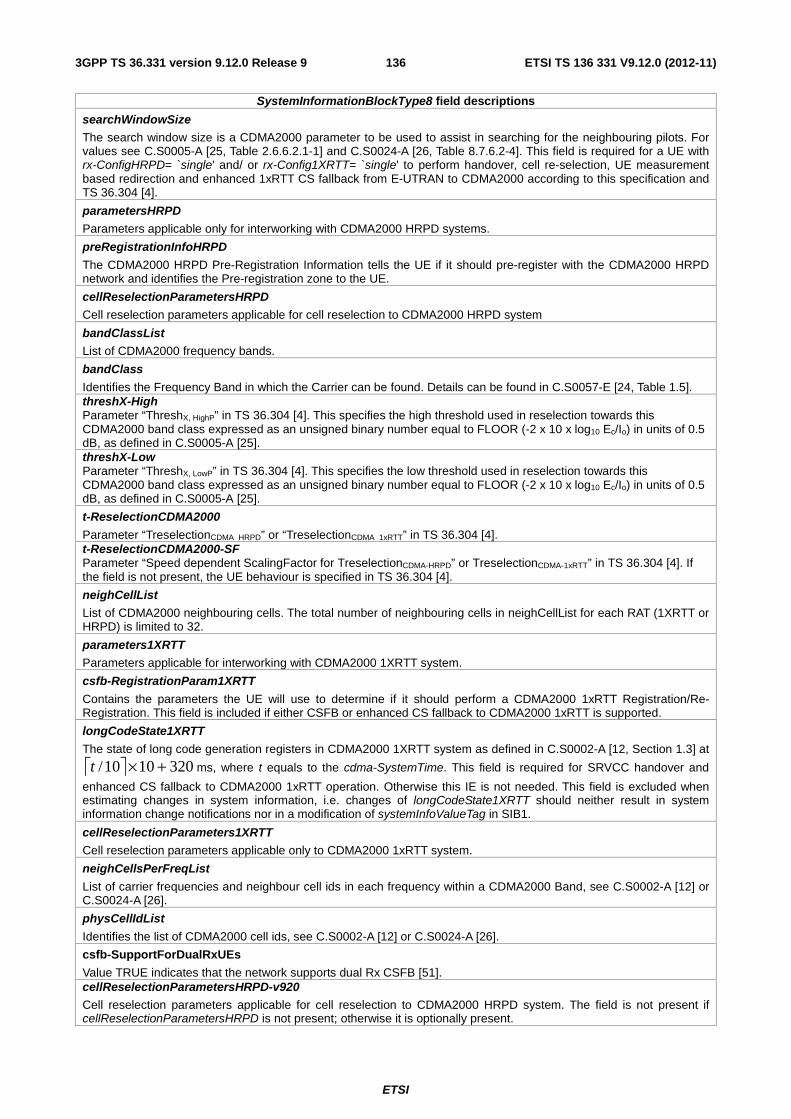
ETSI
ETSI TS 136 331 V9.12.0 (2012-11)1363GPP TS 36.331 version 9.12.0 Release 9
SystemInformationBlockType8 field descriptions
searchWindowSize
The search window size is a CDMA2000 parameter to be used to assist in searching for the neighbouring pilots. For values see C.S0005-A [25, Table 2.6.6.2.1-1] and C.S0024-A [26, Table 8.7.6.2-4]. This field is required for a UE with rx-ConfigHRPD= `single' and/ or rx-Config1XRTT= `single' to perform handover, cell re-selection, UE measurement based redirection and enhanced 1xRTT CS fallback from E-UTRAN to CDMA2000 according to this specification and TS 36.304 [4].
parametersHRPD
Parameters applicable only for interworking with CDMA2000 HRPD systems.
preRegistrationInfoHRPD
The CDMA2000 HRPD Pre-Registration Information tells the UE if it should pre-register with the CDMA2000 HRPD network and identifies the Pre-registration zone to the UE.
cellReselectionParametersHRPD
Cell reselection parameters applicable for cell reselection to CDMA2000 HRPD system
bandClassList
List of CDMA2000 frequency bands.
bandClass
Identifies the Frequency Band in which the Carrier can be found. Details can be found in C.S0057-E [24, Table 1.5]. threshX-High Parameter “ThreshX, HighP” in TS 36.304 [4]. This specifies the high threshold used in reselection towards this CDMA2000 band class expressed as an unsigned binary number equal to FLOOR (-2 x 10 x log10 Ec/Io) in units of 0.5 dB, as defined in C.S0005-A [25]. threshX-Low Parameter “ThreshX, LowP” in TS 36.304 [4]. This specifies the low threshold used in reselection towards this CDMA2000 band class expressed as an unsigned binary number equal to FLOOR (-2 x 10 x log10 Ec/Io) in units of 0.5 dB, as defined in C.S0005-A [25].
t-ReselectionCDMA2000
Parameter “TreselectionCDMA_HRPD” or “TreselectionCDMA_1xRTT” in TS 36.304 [4]. t-ReselectionCDMA2000-SF Parameter “Speed dependent ScalingFactor for TreselectionCDMA-HRPD” or TreselectionCDMA-1xRTT” in TS 36.304 [4]. If the field is not present, the UE behaviour is specified in TS 36.304 [4].
neighCellList
List of CDMA2000 neighbouring cells. The total number of neighbouring cells in neighCellList for each RAT (1XRTT or HRPD) is limited to 32.
parameters1XRTT
Parameters applicable for interworking with CDMA2000 1XRTT system.
csfb-RegistrationParam1XRTT
Contains the parameters the UE will use to determine if it should perform a CDMA2000 1xRTT Registration/Re-Registration. This field is included if either CSFB or enhanced CS fallback to CDMA2000 1xRTT is supported.
longCodeState1XRTT
The state of long code generation registers in CDMA2000 1XRTT system as defined in C.S0002-A [12, Section 1.3] at
⎡ ⎤ 3201010/ +×t ms, where t equals to the cdma-SystemTime. This field is required for SRVCC handover and
enhanced CS fallback to CDMA2000 1xRTT operation. Otherwise this IE is not needed. This field is excluded when estimating changes in system information, i.e. changes of longCodeState1XRTT should neither result in system information change notifications nor in a modification of systemInfoValueTag in SIB1.
cellReselectionParameters1XRTT
Cell reselection parameters applicable only to CDMA2000 1xRTT system.
neighCellsPerFreqList
List of carrier frequencies and neighbour cell ids in each frequency within a CDMA2000 Band, see C.S0002-A [12] or C.S0024-A [26].
physCellIdList
Identifies the list of CDMA2000 cell ids, see C.S0002-A [12] or C.S0024-A [26].
csfb-SupportForDualRxUEs
Value TRUE indicates that the network supports dual Rx CSFB [51]. cellReselectionParametersHRPD-v920
Cell reselection parameters applicable for cell reselection to CDMA2000 HRPD system. The field is not present if cellReselectionParametersHRPD is not present; otherwise it is optionally present.
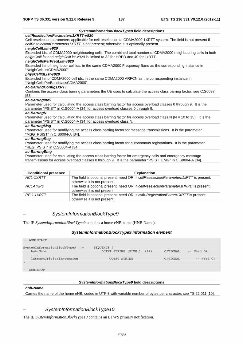
ETSI
ETSI TS 136 331 V9.12.0 (2012-11)1373GPP TS 36.331 version 9.12.0 Release 9
SystemInformationBlockType8 field descriptions cellReselectionParameters1XRTT-v920 Cell reselection parameters applicable for cell reselection to CDMA2000 1XRTT system. The field is not present if cellReselectionParameters1XRTT is not present; otherwise it is optionally present. neighCellList-v920 Extended List of CDMA2000 neighbouring cells. The combined total number of CDMA2000 neighbouring cells in both neighCellList and neighCellList-v920 is limited to 32 for HRPD and 40 for 1xRTT. neighCellsPerFreqList-v920 Extended list of neighbour cell ids, in the same CDMA2000 Frequency Band as the corresponding instance in “NeighCellListCDMA2000”. physCellIdList-v920 Extended list of CDMA2000 cell ids, in the same CDMA2000 ARFCN as the corresponding instance in “NeighCellsPerBandclassCDMA2000”. ac-BarringConfig1XRTT Contains the access class barring parameters the UE uses to calculate the access class barring factor, see C.S0097 [53]. ac-Barring0to9 Parameter used for calculating the access class barring factor for access overload classes 0 through 9. It is the parameter “PSIST” in C.S0004-A [34] for access overload classes 0 through 9. ac-BarringN Parameter used for calculating the access class barring factor for access overload class N (N = 10 to 15). It is the parameter “PSIST” in C.S0004-A [34] for access overload class N. ac-BarringMsg Parameter used for modifying the access class barring factor for message transmissions. It is the parameter “MSG_PSIST” in C.S0004-A [34]. ac-BarringReg Parameter used for modifying the access class barring factor for autonomous registrations. It is the parameter “REG_PSIST” in C.S0004-A [34]. ac-BarringEmg Parameter used for calculating the access class barring factor for emergency calls and emergency message transmissions for access overload classes 0 through 9. It is the parameter “PSIST_EMG” in C.S0004-A [34].
Conditional presence Explanation NCL-1XRTT The field is optional present, need OR, if cellReselectionParameters1xRTT is present;
otherwise it is not present. NCL-HRPD The field is optional present, need OR, if cellReselectionParametersHRPD is present;
otherwise it is not present. REG-1XRTT The field is optional present, need OR, if csfb-RegistrationParam1XRTT is present;
otherwise it is not present.
– SystemInformationBlockType9
The IE SystemInformationBlockType9 contains a home eNB name (HNB Name).
SystemInformationBlockType9 information element
-- ASN1START SystemInformationBlockType9 ::= SEQUENCE { hnb-Name OCTET STRING (SIZE(1..48)) OPTIONAL, -- Need OR ..., lateNonCriticalExtension OCTET STRING OPTIONAL -- Need OP } -- ASN1STOP
SystemInformationBlockType9 field descriptions
hnb-Name
Carries the name of the home eNB, coded in UTF-8 with variable number of bytes per character, see TS 22.011 [10].
– SystemInformationBlockType10
The IE SystemInformationBlockType10 contains an ETWS primary notification.
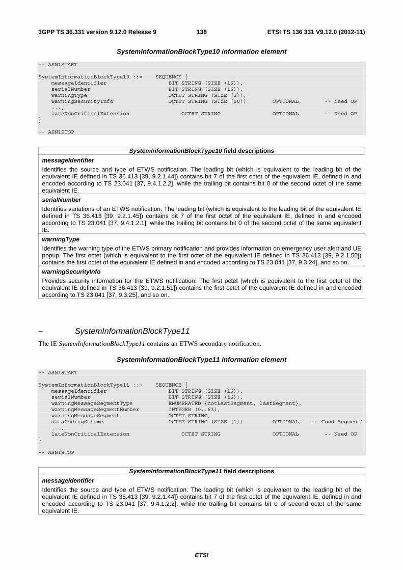
ETSI
ETSI TS 136 331 V9.12.0 (2012-11)1383GPP TS 36.331 version 9.12.0 Release 9
SystemInformationBlockType10 information element
-- ASN1START SystemInformationBlockType10 ::= SEQUENCE { messageIdentifier BIT STRING (SIZE (16)), serialNumber BIT STRING (SIZE (16)), warningType OCTET STRING (SIZE (2)), warningSecurityInfo OCTET STRING (SIZE (50)) OPTIONAL, -- Need OP ..., lateNonCriticalExtension OCTET STRING OPTIONAL -- Need OP } -- ASN1STOP
SystemInformationBlockType10 field descriptions
messageIdentifier
Identifies the source and type of ETWS notification. The leading bit (which is equivalent to the leading bit of the equivalent IE defined in TS 36.413 [39, 9.2.1.44]) contains bit 7 of the first octet of the equivalent IE, defined in and encoded according to TS 23.041 [37, 9.4.1.2.2], while the trailing bit contains bit 0 of the second octet of the same equivalent IE.
serialNumber
Identifies variations of an ETWS notification. The leading bit (which is equivalent to the leading bit of the equivalent IE defined in TS 36.413 [39, 9.2.1.45]) contains bit 7 of the first octet of the equivalent IE, defined in and encoded according to TS 23.041 [37, 9.4.1.2.1], while the trailing bit contains bit 0 of the second octet of the same equivalent IE.
warningType
Identifies the warning type of the ETWS primary notification and provides information on emergency user alert and UE popup. The first octet (which is equivalent to the first octet of the equivalent IE defined in TS 36.413 [39, 9.2.1.50]) contains the first octet of the equivalent IE defined in and encoded according to TS 23.041 [37, 9.3.24], and so on.
warningSecurityInfo
Provides security information for the ETWS notification. The first octet (which is equivalent to the first octet of the equivalent IE defined in TS 36.413 [39, 9.2.1.51]) contains the first octet of the equivalent IE defined in and encoded according to TS 23.041 [37, 9.3.25], and so on.
– SystemInformationBlockType11
The IE SystemInformationBlockType11 contains an ETWS secondary notification.
SystemInformationBlockType11 information element
-- ASN1START SystemInformationBlockType11 ::= SEQUENCE { messageIdentifier BIT STRING (SIZE (16)), serialNumber BIT STRING (SIZE (16)), warningMessageSegmentType ENUMERATED {notLastSegment, lastSegment}, warningMessageSegmentNumber INTEGER (0..63), warningMessageSegment OCTET STRING, dataCodingScheme OCTET STRING (SIZE (1)) OPTIONAL, -- Cond Segment1 ..., lateNonCriticalExtension OCTET STRING OPTIONAL -- Need OP } -- ASN1STOP
SystemInformationBlockType11 field descriptions
messageIdentifier
Identifies the source and type of ETWS notification. The leading bit (which is equivalent to the leading bit of the equivalent IE defined in TS 36.413 [39, 9.2.1.44]) contains bit 7 of the first octet of the equivalent IE, defined in and encoded according to TS 23.041 [37, 9.4.1.2.2], while the trailing bit contains bit 0 of second octet of the same equivalent IE.
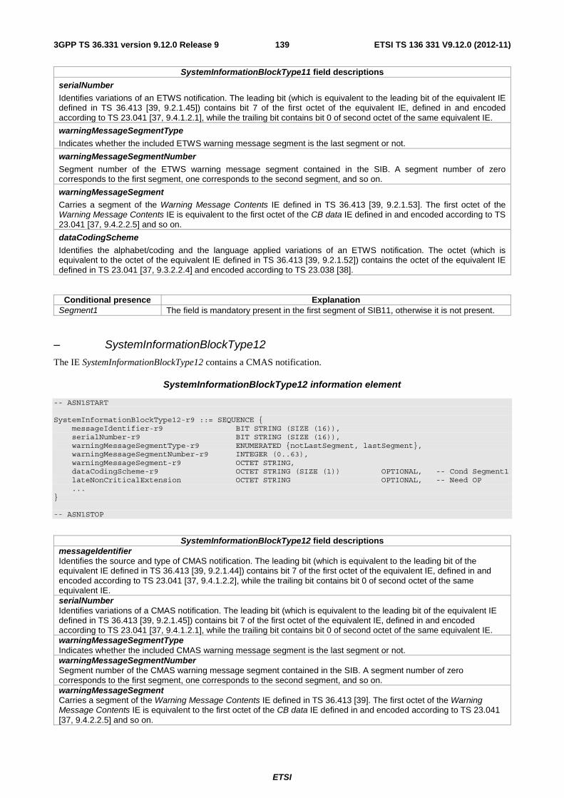
ETSI
ETSI TS 136 331 V9.12.0 (2012-11)1393GPP TS 36.331 version 9.12.0 Release 9
SystemInformationBlockType11 field descriptions
serialNumber
Identifies variations of an ETWS notification. The leading bit (which is equivalent to the leading bit of the equivalent IE defined in TS 36.413 [39, 9.2.1.45]) contains bit 7 of the first octet of the equivalent IE, defined in and encoded according to TS 23.041 [37, 9.4.1.2.1], while the trailing bit contains bit 0 of second octet of the same equivalent IE.
warningMessageSegmentType
Indicates whether the included ETWS warning message segment is the last segment or not.
warningMessageSegmentNumber
Segment number of the ETWS warning message segment contained in the SIB. A segment number of zero corresponds to the first segment, one corresponds to the second segment, and so on.
warningMessageSegment Carries a segment of the Warning Message Contents IE defined in TS 36.413 [39, 9.2.1.53]. The first octet of the Warning Message Contents IE is equivalent to the first octet of the CB data IE defined in and encoded according to TS 23.041 [37, 9.4.2.2.5] and so on.
dataCodingScheme
Identifies the alphabet/coding and the language applied variations of an ETWS notification. The octet (which is equivalent to the octet of the equivalent IE defined in TS 36.413 [39, 9.2.1.52]) contains the octet of the equivalent IE defined in TS 23.041 [37, 9.3.2.2.4] and encoded according to TS 23.038 [38].
Conditional presence Explanation Segment1 The field is mandatory present in the first segment of SIB11, otherwise it is not present.
– SystemInformationBlockType12
The IE SystemInformationBlockType12 contains a CMAS notification.
SystemInformationBlockType12 information element
-- ASN1START SystemInformationBlockType12-r9 ::= SEQUENCE { messageIdentifier-r9 BIT STRING (SIZE (16)), serialNumber-r9 BIT STRING (SIZE (16)), warningMessageSegmentType-r9 ENUMERATED {notLastSegment, lastSegment}, warningMessageSegmentNumber-r9 INTEGER (0..63), warningMessageSegment-r9 OCTET STRING, dataCodingScheme-r9 OCTET STRING (SIZE (1)) OPTIONAL, -- Cond Segment1 lateNonCriticalExtension OCTET STRING OPTIONAL, -- Need OP ... } -- ASN1STOP
SystemInformationBlockType12 field descriptions messageIdentifier Identifies the source and type of CMAS notification. The leading bit (which is equivalent to the leading bit of the equivalent IE defined in TS 36.413 [39, 9.2.1.44]) contains bit 7 of the first octet of the equivalent IE, defined in and encoded according to TS 23.041 [37, 9.4.1.2.2], while the trailing bit contains bit 0 of second octet of the same equivalent IE. serialNumber Identifies variations of a CMAS notification. The leading bit (which is equivalent to the leading bit of the equivalent IE defined in TS 36.413 [39, 9.2.1.45]) contains bit 7 of the first octet of the equivalent IE, defined in and encoded according to TS 23.041 [37, 9.4.1.2.1], while the trailing bit contains bit 0 of second octet of the same equivalent IE. warningMessageSegmentType Indicates whether the included CMAS warning message segment is the last segment or not. warningMessageSegmentNumber Segment number of the CMAS warning message segment contained in the SIB. A segment number of zero corresponds to the first segment, one corresponds to the second segment, and so on. warningMessageSegment Carries a segment of the Warning Message Contents IE defined in TS 36.413 [39]. The first octet of the Warning Message Contents IE is equivalent to the first octet of the CB data IE defined in and encoded according to TS 23.041 [37, 9.4.2.2.5] and so on.

ETSI
ETSI TS 136 331 V9.12.0 (2012-11)1403GPP TS 36.331 version 9.12.0 Release 9
SystemInformationBlockType12 field descriptions dataCodingScheme Identifies the alphabet/coding and the language applied variations of a CMAS notification. The octet (which is equivalent to the octet of the equivalent IE defined in TS 36.413 [39, 9.2.1.52]) contains the octet of the equivalent IE defined in TS 23.041 [37, 9.3.2.2.4] and encoded according to TS 23.038 [38].
Conditional presence Explanation Segment1 The field is mandatory present in the first segment of SIB12, otherwise it is not present.
– SystemInformationBlockType13
The IE SystemInformationBlockType13 contains the information required to acquire the MBMS control information associated with one or more MBSFN areas.
SystemInformationBlockType13 information element
-- ASN1START SystemInformationBlockType13-r9 ::= SEQUENCE { mbsfn-AreaInfoList-r9 MBSFN-AreaInfoList-r9,
notificationConfig-r9 MBMS-NotificationConfig-r9, lateNonCriticalExtension OCTET STRING OPTIONAL, -- Need OP ... } -- ASN1STOP
SystemInformationBlockType13 field descriptions
6.3.2 Radio resource control information elements
– AntennaInfo
The IE AntennaInfoCommon and the AntennaInfoDedicated are used to specify the common and the UE specific antenna configuration respectively.
AntennaInfo information elements
-- ASN1START AntennaInfoCommon ::= SEQUENCE { antennaPortsCount ENUMERATED {an1, an2, an4, spare1} } AntennaInfoDedicated ::= SEQUENCE { transmissionMode ENUMERATED { tm1, tm2, tm3, tm4, tm5, tm6, tm7, tm8-v920}, codebookSubsetRestriction CHOICE { n2TxAntenna-tm3 BIT STRING (SIZE (2)), n4TxAntenna-tm3 BIT STRING (SIZE (4)), n2TxAntenna-tm4 BIT STRING (SIZE (6)), n4TxAntenna-tm4 BIT STRING (SIZE (64)), n2TxAntenna-tm5 BIT STRING (SIZE (4)), n4TxAntenna-tm5 BIT STRING (SIZE (16)), n2TxAntenna-tm6 BIT STRING (SIZE (4)), n4TxAntenna-tm6 BIT STRING (SIZE (16)) } OPTIONAL, -- Cond TM ue-TransmitAntennaSelection CHOICE{ release NULL, setup ENUMERATED {closedLoop, openLoop} } } AntennaInfoDedicated-v920 ::= SEQUENCE {

ETSI
ETSI TS 136 331 V9.12.0 (2012-11)1413GPP TS 36.331 version 9.12.0 Release 9
codebookSubsetRestriction-v920 CHOICE { n2TxAntenna-tm8-r9 BIT STRING (SIZE (6)), n4TxAntenna-tm8-r9 BIT STRING (SIZE (32)) } OPTIONAL -- Cond TM8 } -- ASN1STOP
AntennaInfo field descriptions antennaPortsCount Parameter represents the number of cell specific antenna ports where an1 corresponds to 1, an2 to 2 antenna ports etc. see TS 36.211 [21, 6.2.1]. transmissionMode Points to one of Transmission modes defined in TS 36.213 [23, 7.1] where tm1 refers to transmission mode 1, tm2 to transmission mode 2 etc. codebookSubsetRestriction Parameter: codebookSubsetRestriction, see TS 36.213 [23, 7.2] and TS 36.211 [21, 6.3.4.2.3]. The field codebookSubsetRestriction-v920 is applicable only if PMI/RI reporting is configured. ue-TransmitAntennaSelection For value setup the field indicates whether UE transmit antenna selection control is closed-loop or open-loop as described in TS 36.213 [23, 8.7].
Conditional presence Explanation TM The field is mandatory present if the transmissionMode is set to tm3, tm4, tm5 or tm6.
Otherwise the field is not present and the UE shall delete any existing value for this field. TM8 The field is optional present, need OR, if AntennaInfoDedicated is included and
transmissionMode is set to tm8. If AntennaInfoDedicated is included and transmissionMode is set to a value other than tm8, the field is not present and the UE shall delete any existing value for this field. Otherwise the field is not present and the UE takes no action i.e. continues to use the existing value, if previously configured.
– CQI-ReportConfig
The IE CQI-ReportConfig is used to specify the CQI reporting configuration.
CQI-ReportConfig information elements
-- ASN1START CQI-ReportConfig ::= SEQUENCE { cqi-ReportModeAperiodic ENUMERATED { rm12, rm20, rm22, rm30, rm31, spare3, spare2, spare1} OPTIONAL, -- Need OR nomPDSCH-RS-EPRE-Offset INTEGER (-1..6), cqi-ReportPeriodic CQI-ReportPeriodic OPTIONAL -- Need ON } CQI-ReportConfig-v920 ::= SEQUENCE { cqi-Mask-r9 ENUMERATED {setup} OPTIONAL, -- Cond cqi-Setup pmi-RI-Report-r9 ENUMERATED {setup} OPTIONAL -- Cond PMIRI } CQI-ReportPeriodic ::= CHOICE { release NULL, setup SEQUENCE { cqi-PUCCH-ResourceIndex INTEGER (0.. 1185), cqi-pmi-ConfigIndex INTEGER (0..1023), cqi-FormatIndicatorPeriodic CHOICE { widebandCQI NULL, subbandCQI SEQUENCE { k INTEGER (1..4) } }, ri-ConfigIndex INTEGER (0..1023) OPTIONAL, -- Need OR simultaneousAckNackAndCQI BOOLEAN } } -- ASN1STOP

ETSI
ETSI TS 136 331 V9.12.0 (2012-11)1423GPP TS 36.331 version 9.12.0 Release 9
CQI-ReportConfig field descriptions cqi-PUCCH-ResourceIndex
Parameter (2)PUCCHn , see TS 36.213 [23, 7.2].
cqi-pmi-ConfigIndex Parameter: CQI/PMI Periodicity and Offset Configuration Index ICQI/PMI, see TS 36.213 [23, tables 7.2.2-1A and 7.2.2-1C]. ri-ConfigIndex Parameter: RI Config Index IRI, see TS 36.213 [23, 7.2.2-1B]. K Parameter: K, see TS 36.213 [23, 7.2.2]. cqi-FormatIndicatorPeriodic Parameter: PUCCH CQI Feedback Type, see TS 36.213 [23, table 7.2.2-1]. Depending on transmissionMode, reporting mode is implicitly given from the table. simultaneousAckNackAndCQI Parameter: Simultaneous-AN-and-CQI. see TS 36.213 [23, 10.1] TRUE indicates that simultaneous transmission of ACK/NACK and CQI is allowed. cqi-ReportModeAperiodic Parameter: reporting mode. Value rm12 corresponds to Mode 1-2, rm20 corresponds to Mode 2-0, rm22 corresponds to Mode 2-2 etc. PUSCH reporting modes are described in TS 36.213 [23, 7.2.1]. nomPDSCH-RS-EPRE-Offset
Parameter: offsetΔ see TS 36.213 [23, 7.2.3]. Actual value = IE value * 2 [dB].
cqi-Mask Limits CQI/PMI/RI reports to the on-duration period of the DRX cycle, see TS 36.321 [6]. pmi-RI-Report See TS 36.213 [23, 7.2]. The presence of this field means PMI/RI reporting is configured, which is applicable only when transmissionMode is set to tm8; otherwise PMI/RI reporting is not configured.
Conditional presence Explanation cqi-Setup The field is optional present, need OR, if the cqi-ReportPeriodic in the cqi-ReportConfig is
set to ‘setup’. If the field cqi-ReportPeriodic is present and set to ‘release’, the field is not present and the UE shall delete any existing value for this field. Otherwise the field is not present and the UE takes no action i.e. continues to use the existing value, if previously configured.
PMIRI The field is optional present, need OR, if cqi-ReportPeriodic is included and set to ‘setup’, or cqi-ReportModeAperiodic is included. If the field cqi-ReportPeriodic is present and set to ‘release’ and cqi-ReportModeAperiodic is absent, the field is not present and the UE shall delete any existing value for this field. Otherwise the field is not present and the UE takes no action i.e. continues to use the existing value, if previously configured.
– DRB-Identity
The IE DRB-Identity is used to identify a DRB used by a UE.
DRB-Identity information elements
-- ASN1START DRB-Identity ::= INTEGER (1..32) -- ASN1STOP
– LogicalChannelConfig
The IE LogicalChannelConfig is used to configure the logical channel parameters.
LogicalChannelConfig information element
-- ASN1START LogicalChannelConfig ::= SEQUENCE {

ETSI
ETSI TS 136 331 V9.12.0 (2012-11)1433GPP TS 36.331 version 9.12.0 Release 9
ul-SpecificParameters SEQUENCE { priority INTEGER (1..16), prioritisedBitRate ENUMERATED { kBps0, kBps8, kBps16, kBps32, kBps64, kBps128, kBps256, infinity, spare8, spare7, spare6, spare5, spare4, spare3, spare2, spare1}, bucketSizeDuration ENUMERATED { ms50, ms100, ms150, ms300, ms500, ms1000, spare2, spare1}, logicalChannelGroup INTEGER (0..3) OPTIONAL -- Need OR } OPTIONAL, -- Cond UL ..., [[ logicalChannelSR-Mask-r9 ENUMERATED {setup} OPTIONAL -- Cond SRmask ]] } -- ASN1STOP
LogicalChannelConfig field descriptions priority Logical channel priority in TS 36.321 [6]. Value is an integer. prioritisedBitRate Prioritized Bit Rate for logical channel prioritization in TS 36.321 [6]. Value in kilobytes/second. Value kBps0 corresponds to 0 kB/second, kBps8 corresponds to 8 kB/second, kBps16 corresponds to 16 kB/second and so on. Infinity is the only applicable value for SRB1 and SRB2 bucketSizeDuration Bucket Size Duration for logical channel prioritization in TS 36.321 [6]. Value in milliseconds. Value ms50 corresponds to 50 ms, ms100 corresponds to 100 ms and so on. logicalChannelGroup Mapping of logical channel to logical channel group for BSR reporting in TS 36.321 [6]. logicalChannelSR-Mask Controlling SR triggering on a logical channel basis when an uplink grant is configured. See TS 36.321 [6].
Conditional presence Explanation UL The field is mandatory present for UL logical channels; otherwise it is not present. SRmask The field is optionally present if ul-SpecificParameters is present, need OR; otherwise it is
not present.
– MAC-MainConfig
The IE MAC-MainConfig is used to specify the MAC main configuration for signalling and data radio bearers.
MAC-MainConfig information element
-- ASN1START MAC-MainConfig ::= SEQUENCE { ul-SCH-Config SEQUENCE { maxHARQ-Tx ENUMERATED { n1, n2, n3, n4, n5, n6, n7, n8, n10, n12, n16, n20, n24, n28, spare2, spare1} OPTIONAL, -- Need ON periodicBSR-Timer ENUMERATED { sf5, sf10, sf16, sf20, sf32, sf40, sf64, sf80, sf128, sf160, sf320, sf640, sf1280, sf2560, infinity, spare1} OPTIONAL, -- Need ON retxBSR-Timer ENUMERATED { sf320, sf640, sf1280, sf2560, sf5120, sf10240, spare2, spare1}, ttiBundling BOOLEAN } OPTIONAL, -- Need ON drx-Config DRX-Config OPTIONAL, -- Need ON timeAlignmentTimerDedicated TimeAlignmentTimer, phr-Config CHOICE { release NULL, setup SEQUENCE { periodicPHR-Timer ENUMERATED {sf10, sf20, sf50, sf100, sf200, sf500, sf1000, infinity}, prohibitPHR-Timer ENUMERATED {sf0, sf10, sf20, sf50, sf100,

ETSI
ETSI TS 136 331 V9.12.0 (2012-11)1443GPP TS 36.331 version 9.12.0 Release 9
sf200, sf500, sf1000}, dl-PathlossChange ENUMERATED {dB1, dB3, dB6, infinity} } } OPTIONAL, -- Need ON ..., [[ sr-ProhibitTimer-r9 INTEGER (0..7) OPTIONAL -- Need ON ]] } DRX-Config ::= CHOICE { release NULL, setup SEQUENCE { onDurationTimer ENUMERATED { psf1, psf2, psf3, psf4, psf5, psf6, psf8, psf10, psf20, psf30, psf40, psf50, psf60, psf80, psf100, psf200}, drx-InactivityTimer ENUMERATED { psf1, psf2, psf3, psf4, psf5, psf6, psf8, psf10, psf20, psf30, psf40, psf50, psf60, psf80, psf100, psf200, psf300, psf500, psf750, psf1280, psf1920, psf2560, spare10, spare9, spare8, spare7, spare6, spare5, spare4, spare3, spare2, spare1}, drx-RetransmissionTimer ENUMERATED { psf1, psf2, psf4, psf6, psf8, psf16, psf24, psf33}, longDRX-CycleStartOffset CHOICE { sf10 INTEGER(0..9), sf20 INTEGER(0..19), sf32 INTEGER(0..31), sf40 INTEGER(0..39), sf64 INTEGER(0..63), sf80 INTEGER(0..79), sf128 INTEGER(0..127), sf160 INTEGER(0..159), sf256 INTEGER(0..255), sf320 INTEGER(0..319), sf512 INTEGER(0..511), sf640 INTEGER(0..639), sf1024 INTEGER(0..1023), sf1280 INTEGER(0..1279), sf2048 INTEGER(0..2047), sf2560 INTEGER(0..2559) }, shortDRX SEQUENCE { shortDRX-Cycle ENUMERATED { sf2, sf5, sf8, sf10, sf16, sf20, sf32, sf40, sf64, sf80, sf128, sf160, sf256, sf320, sf512, sf640}, drxShortCycleTimer INTEGER (1..16) } OPTIONAL -- Need OR } } -- ASN1STOP

ETSI
ETSI TS 136 331 V9.12.0 (2012-11)1453GPP TS 36.331 version 9.12.0 Release 9
MAC-MainConfig field descriptions maxHARQ-Tx Maximum number of transmissions for UL HARQ in TS 36.321 [6]. periodicBSR-Timer Timer for BSR reporting in TS 36.321 [6]. Value in number of sub-frames. Value sf10 corresponds to 10 sub-frames, sf20 corresponds to 20 sub-frames and so on. retxBSR-Timer Timer for BSR reporting in TS 36.321 [6]. Value in number of sub-frames. Value sf640 corresponds to 640 sub-frames, sf1280 corresponds to 1280 sub-frames and so on. ttiBundling TRUE indicates that TTI bundling TS 36.321 [6] is enabled while FALSE indicates that TTI bundling is disabled. TTI bundling can be enabled for FDD and for TDD only for configurations 0, 1 and 6. For TDD, E-UTRAN does not simultaneously enable TTI bundling and semi-persistent scheduling in this release of specification. longDRX-CycleStartOffset longDRX-Cycle and drxStartOffset in TS 36.321 [6]. The value of longDRX-Cycle is in number of sub-frames. Value sf10 corresponds to 10 sub-frames, sf20 corresponds to 20 sub-frames and so on. If shortDRX-Cycle is configured, the value of longDRX-Cycle shall be a multiple of the shortDRX-Cycle value. The value of drxStartOffset value is in number of sub-frames. onDurationTimer Timer for DRX in TS 36.321 [6]. Value in number of PDCCH sub-frames. Value psf1 corresponds to 1 PDCCH sub-frame, psf2 corresponds to 2 PDCCH sub-frames and so on. drx-InactivityTimer Timer for DRX in TS 36.321 [6]. Value in number of PDCCH sub-frames. Value psf1 corresponds to 1 PDCCH sub-frame, psf2 corresponds to 2 PDCCH sub-frames and so on. drx-RetransmissionTimer Timer for DRX in TS 36.321 [6]. Value in number of PDCCH sub-frames. Value psf1 corresponds to 1 PDCCH sub-frame, psf2 corresponds to 2 PDCCH sub-frames and so on. shortDRX-Cycle Short DRX cycle in TS 36.321 [6]. Value in number of sub-frames. Value sf2 corresponds to 2 sub-frames, sf5 corresponds to 5 subframes and so on. drxShortCycleTimer Timer for DRX in TS 36.321 [6]. Value in multiples of shortDRX-Cycle. A value of 1 corresponds to shortDRX-Cycle, a value of 2 corresponds to 2 * shortDRX-Cycle and so on. periodicPHR-Timer Timer for PHR reporting in TS 36.321 [6]. Value in number of sub-frames. Value sf10 corresponds to 10 subframes, sf20 corresponds to 20 subframes and so on. prohibitPHR-Timer Timer for PHR reporting in TS 36.321 [6]. Value in number of sub-frames. Value sf0 corresponds to 0 subframes, sf100 corresponds to 100 subframes and so on. dl-PathlossChange DL Pathloss Change for PHR reporting in TS 36.321 [6]. Value in dB. Value dB1 corresponds to 1 dB, dB3 corresponds to 3 dB and so on. sr-ProhibitTimer Timer for SR transmission on PUCCH in TS 36.321 [6]. Value in number of SR period(s). Value 0 means no timer for SR transmission on PUCCH is configured. Value 1 corresponds to one SR period, Value 2 corresponds to 2*SR periods and so on.
– PDCP-Config
The IE PDCP-Config is used to set the configurable PDCP parameters for data radio bearers.
PDCP-Config information element
-- ASN1START PDCP-Config ::= SEQUENCE { discardTimer ENUMERATED { ms50, ms100, ms150, ms300, ms500, ms750, ms1500, infinity } OPTIONAL, -- Cond Setup rlc-AM SEQUENCE { statusReportRequired BOOLEAN } OPTIONAL, -- Cond Rlc-AM rlc-UM SEQUENCE { pdcp-SN-Size ENUMERATED {len7bits, len12bits} } OPTIONAL, -- Cond Rlc-UM headerCompression CHOICE { notUsed NULL,

ETSI
ETSI TS 136 331 V9.12.0 (2012-11)1463GPP TS 36.331 version 9.12.0 Release 9
rohc SEQUENCE { maxCID INTEGER (1..16383) DEFAULT 15, profiles SEQUENCE { profile0x0001 BOOLEAN, profile0x0002 BOOLEAN, profile0x0003 BOOLEAN, profile0x0004 BOOLEAN, profile0x0006 BOOLEAN, profile0x0101 BOOLEAN, profile0x0102 BOOLEAN, profile0x0103 BOOLEAN, profile0x0104 BOOLEAN }, ... } }, ... } -- ASN1STOP
PDCP-Config field descriptions discardTimer Indicates the discard timer value specified in TS 36.323 [8]. Value in milliseconds. Value ms50 means 50 ms, ms100 means 100 ms and so on. statusReportRequired Indicates whether or not the UE shall send a PDCP Status Report upon re-establishment of the PDCP entity as specified in TS 36.323 [8]. pdcp-SN-Size Indicates the PDCP Sequence Number length in bits. Value len7bits means that the 7-bit PDCP SN format is used and len12bits means that the 12-bit PDCP SN format is used, as specified in TS 36.323 [8]. maxCID Indicates the value of the MAX_CID parameter as specified in TS 36.323 [8]. profiles The profiles used by both compressor and decompressor in both UE and E-UTRAN. The field indicates which of the ROHC profiles specified in TS 36.323 [8] are supported, i.e. value 'true' indicates that the profile is supported. Profile 0x0000 shall always be supported when the use of ROHC is configured. If support of two ROHC profile identifiers with the same 8 LSB’s is signalled, only the profile corresponding to the highest value shall be applied.
Conditional presence Explanation
Setup The field is mandatory present in case of radio bearer setup. Otherwise the field is not present.
Rlc-AM The field is mandatory present upon setup of a PDCP entity for a radio bearer configured with RLC AM. The field is optional, need ON, in case of reconfiguration of a PDCP entity at handover for a radio bearer configured with RLC AM. Otherwise the field is not present.
Rlc-UM The field is mandatory present upon setup of a PDCP entity for a radio bearer configured with RLC UM. Otherwise the field is not present.
– PDSCH-Config
The IE PDSCH-ConfigCommon and the IE PDSCH-ConfigDedicated are used to specify the common and the UE specific PDSCH configuration respectively.
PDSCH-Config information element
-- ASN1START PDSCH-ConfigCommon ::= SEQUENCE { referenceSignalPower INTEGER (-60..50), p-b INTEGER (0..3) } PDSCH-ConfigDedicated::= SEQUENCE { p-a ENUMERATED {

ETSI
ETSI TS 136 331 V9.12.0 (2012-11)1473GPP TS 36.331 version 9.12.0 Release 9
dB-6, dB-4dot77, dB-3, dB-1dot77, dB0, dB1, dB2, dB3} } -- ASN1STOP
PDSCH-Config field descriptions referenceSignalPower Parameter: Reference-signal power, which provides the downlink reference-signal EPRE, see TS 36.213 [23, 5.2]. The actual value in dBm. p-a Parameter: AP , see TS 36.213 [23, 5.2]. Value dB-6 corresponds to -6 dB, dB-4dot77 corresponds to -4.77 dB etc.
p-b Parameter: BP , see TS 36.213 [23, Table 5.2-1].
– PHICH-Config
The IE PHICH-Config is used to specify the PHICH configuration.
PHICH-Config information element
-- ASN1START PHICH-Config ::= SEQUENCE { phich-Duration ENUMERATED {normal, extended}, phich-Resource ENUMERATED {oneSixth, half, one, two} } -- ASN1STOP
PHICH-Config field descriptions phich-Duration Parameter: PHICH-Duration, see TS 36.211 [21, Table 6.9.3-1]. phich-Resource Parameter: Ng, see TS 36.211 [21, 6.9]. Value oneSixth corresponds to 1/6, half corresponds to 1/2 and so on.
– PhysicalConfigDedicated
The IE PhysicalConfigDedicated is used to specify the UE specific physical channel configuration.
PhysicalConfigDedicated information element
-- ASN1START PhysicalConfigDedicated ::= SEQUENCE { pdsch-ConfigDedicated PDSCH-ConfigDedicated OPTIONAL, -- Need ON pucch-ConfigDedicated PUCCH-ConfigDedicated OPTIONAL, -- Need ON pusch-ConfigDedicated PUSCH-ConfigDedicated OPTIONAL, -- Need ON uplinkPowerControlDedicated UplinkPowerControlDedicated OPTIONAL, -- Need ON tpc-PDCCH-ConfigPUCCH TPC-PDCCH-Config OPTIONAL, -- Need ON tpc-PDCCH-ConfigPUSCH TPC-PDCCH-Config OPTIONAL, -- Need ON cqi-ReportConfig CQI-ReportConfig OPTIONAL, -- Need ON soundingRS-UL-ConfigDedicated SoundingRS-UL-ConfigDedicated OPTIONAL, -- Need ON antennaInfo CHOICE { explicitValue AntennaInfoDedicated, defaultValue NULL } OPTIONAL, -- Need ON schedulingRequestConfig SchedulingRequestConfig OPTIONAL, -- Need ON ..., [[ cqi-ReportConfig-v920 CQI-ReportConfig-v920 OPTIONAL, -- Need ON antennaInfo-v920 AntennaInfoDedicated-v920 OPTIONAL -- Need ON ]] } -- ASN1STOP

ETSI
ETSI TS 136 331 V9.12.0 (2012-11)1483GPP TS 36.331 version 9.12.0 Release 9
PhysicalConfigDedicated field descriptions antennaInfo A choice is used to indicate whether the antennaInfo is signalled explicitly or set to the default antenna configuration as specified in section 9.2.4. tpc-PDCCH-ConfigPUCCH PDCCH configuration for power control of PUCCH using format 3/3A, see TS 36.212 [22]. tpc-PDCCH-ConfigPUSCH PDCCH configuration for power control of PUSCH using format 3/3A, see TS 36.212 [22].
NOTE: During handover, the UE performs a MAC reset, which involves reverting to the default CQI/ SRS/ SR configuration in accordance with subclause 5.3.13 and TS 36.321 [6, 5.9 & 5.2]. Hence, for these parts of the dedicated radio resource configuration, the default configuration (rather than the configuration used in the source cell) is used as the basis for the delta signalling that is included in the message used to perform handover.
– P-Max
The IE P-Max is used to limit the UE's uplink transmission power on a carrier frequency and is used to calculate the parameter Pcompensation defined in TS 36.304 [4]. Corresponds to parameter PEMAX in TS 36.101 [42]. The UE transmit power shall not exceed the configured maximum UE output power determined by this value as specified in TS 36.101 [42, 6.2.5].
P-Max information element
-- ASN1START P-Max ::= INTEGER (-30..33) -- ASN1STOP
– PRACH-Config
The IE PRACH-ConfigSIB and IE PRACH-Config are used to specify the PRACH configuration in the system information and in the mobility control information, respectively.
PRACH-Config information elements
-- ASN1START PRACH-ConfigSIB ::= SEQUENCE { rootSequenceIndex INTEGER (0..837), prach-ConfigInfo PRACH-ConfigInfo } PRACH-Config ::= SEQUENCE { rootSequenceIndex INTEGER (0..837), prach-ConfigInfo PRACH-ConfigInfo OPTIONAL -- Need ON } PRACH-ConfigInfo ::= SEQUENCE { prach-ConfigIndex INTEGER (0..63), highSpeedFlag BOOLEAN, zeroCorrelationZoneConfig INTEGER (0..15), prach-FreqOffset INTEGER (0..94) } -- ASN1STOP

ETSI
ETSI TS 136 331 V9.12.0 (2012-11)1493GPP TS 36.331 version 9.12.0 Release 9
PRACH-Config field descriptions rootSequenceIndex Parameter: RACH_ROOT_SEQUENCE, see TS 36.211 [21, 5.7.1]. prach-ConfigIndex Parameter: prach-ConfigurationIndex, see TS 36.211 [21, 5.7.1]. highSpeedFlag Parameter: High-speed-flag, see TS 36.211, [21, 5.7.2].TRUE corresponds to Restricted set and FALSE to Unrestricted set. zeroCorrelationZoneConfig Parameter: NCS configuration, see TS 36.211, [21, 5.7.2: table 5.7.2-2] for preamble format 0..3 and TS 36.211, [21, 5.7.2: table 5.7.2-3] for preamble format 4. prach-FreqOffset Parameter: prach-FrequencyOffset, see TS 36.211, [21, 5.7.1]. For TDD the value range is dependent on the value of prach-ConfigIndex.
– PresenceAntennaPort1
The IE PresenceAntennaPort1 is used to indicate whether all the neighbouring cells use Antenna Port 1. When set to TRUE, the UE may assume that at least two cell-specific antenna ports are used in all neighbouring cells.
PresenceAntennaPort1 information element
-- ASN1START PresenceAntennaPort1 ::= BOOLEAN -- ASN1STOP
– PUCCH-Config
The IE PUCCH-ConfigCommon and IE PUCCH-ConfigDedicated are used to specify the common and the UE specific PUCCH configuration respectively.
PUCCH-Config information elements
-- ASN1START PUCCH-ConfigCommon ::= SEQUENCE { deltaPUCCH-Shift ENUMERATED {ds1, ds2, ds3}, nRB-CQI INTEGER (0..98), nCS-AN INTEGER (0..7), n1PUCCH-AN INTEGER (0..2047) } PUCCH-ConfigDedicated ::= SEQUENCE { ackNackRepetition CHOICE{ release NULL, setup SEQUENCE { repetitionFactor ENUMERATED {n2, n4, n6, spare1}, n1PUCCH-AN-Rep INTEGER (0..2047) } }, tdd-AckNackFeedbackMode ENUMERATED {bundling, multiplexing} OPTIONAL -- Cond TDD } -- ASN1STOP

ETSI
ETSI TS 136 331 V9.12.0 (2012-11)1503GPP TS 36.331 version 9.12.0 Release 9
PUCCH-Config field descriptions deltaPUCCH-Shift
Parameter: PUCCHshiftΔ , see 36.211, 5.4.1, where ds1 corresponds to value 1 ds2 to 2 etc.
nRB-CQI
Parameter: (2)RBN , see TS 36.211 [21, 5.4].
nCS-An
Parameter: )1(csN see TS 36.211 [21, 5.4].
n1Pucch-AN
Parameter: )1(PUCCHN see TS 36.213 [23, 10.1].
ackNackRepetition Parameter indicates whether ACK/NACK repetition is configured, see TS 36.213 [23, 10.1]. repetitionFactor
Parameter ANRepN see TS 36.213 [23, 10.1] where n2 corresponds to repetition factor 2, n4 to 4.
n1Pucch-AN-Rep
Parameter: )1(
ANRep PUCCH,n see TS 36.213 [23, 10.1].
tdd-AckNackFeedbackMode Parameter indicates one of the two TDD ACK/NACK feedback modes used, see TS 36.213 [23, 7.3]. bundling corresponds to use of ACK/NACK bundling whereas, multiplexing corresponds to ACK/NACK multiplexing. The same value applies to both ACK/NACK feedback modes on PUCCH as well as on PUSCH. For TDD configuration 5, E-UTRAN should always set this field to bundling.
Conditional presence Explanation TDD The field is mandatory present for TDD; it is not present for FDD and the UE shall delete
any existing value for this field.
– PUSCH-Config
The IE PUSCH-ConfigCommon is used to specify the common PUSCH configuration and the reference signal configuration for PUSCH and PUCCH. The IE PUSCH-ConfigDedicated is used to specify the UE specific PUSCH configuration.
PUSCH-Config information element
-- ASN1START PUSCH-ConfigCommon ::= SEQUENCE { pusch-ConfigBasic SEQUENCE { n-SB INTEGER (1..4), hoppingMode ENUMERATED {interSubFrame, intraAndInterSubFrame}, pusch-HoppingOffset INTEGER (0..98), enable64QAM BOOLEAN }, ul-ReferenceSignalsPUSCH UL-ReferenceSignalsPUSCH } PUSCH-ConfigDedicated ::= SEQUENCE { betaOffset-ACK-Index INTEGER (0..15), betaOffset-RI-Index INTEGER (0..15), betaOffset-CQI-Index INTEGER (0..15) } UL-ReferenceSignalsPUSCH ::= SEQUENCE { groupHoppingEnabled BOOLEAN, groupAssignmentPUSCH INTEGER (0..29), sequenceHoppingEnabled BOOLEAN, cyclicShift INTEGER (0..7) } -- ASN1STOP

ETSI
ETSI TS 136 331 V9.12.0 (2012-11)1513GPP TS 36.331 version 9.12.0 Release 9
PUSCH-Config field descriptions n-SB Parameter: Nsb see TS 36.211 [21, 5.3.4]. hoppingMode Parameter: Hopping-mode, see TS 36.211 [21, 5.3.4]. pusch-hoppingOffset
Parameter: HORBN , see TS 36.211 [21, 5.3.4].
enable64QAM See TS 36.213 [23, 8.6.1]. TRUE indicates that 64QAM is allowed while FALSE indicates that 64QAM is not allowed. betaOffset-ACK-Index
Parameter: ACKHARQ
offsetI −, see TS 36.213 [23, Table 8.6.3-1].
betaOffset-RI-Index
Parameter: RIoffsetI , see TS 36.213 [23, Table 8.6.3-2].
betaOffset-CQI-Index
Parameter: CQIoffsetI , see TS 36.213 [23, Table 8.6.3-3].
ul- ReferenceSignalsPUSCH Used to specify parameters needed for the transmission on PUSCH (or PUCCH). groupHoppingEnabled Parameter: Group-hopping-enabled, see TS 36.211 [21, 5.5.1.3]. groupAssignmentPUSCH Parameter: ΔSS See TS 36.211 [21, 5.5.1.3]. sequenceHoppingEnabled Parameter: Sequence-hopping-enabled, see TS 36.211 [21, 5.5.1.4]. cyclicShift Parameters: cyclicShift, see TS 36.211 [21, Table 5.5.2.1.1-2].
– RACH-ConfigCommon
The IE RACH-ConfigCommon is used to specify the generic random access parameters.
RACH-ConfigCommon information element
-- ASN1START RACH-ConfigCommon ::= SEQUENCE { preambleInfo SEQUENCE { numberOfRA-Preambles ENUMERATED { n4, n8, n12, n16 ,n20, n24, n28, n32, n36, n40, n44, n48, n52, n56, n60, n64}, preamblesGroupAConfig SEQUENCE { sizeOfRA-PreamblesGroupA ENUMERATED { n4, n8, n12, n16 ,n20, n24, n28, n32, n36, n40, n44, n48, n52, n56, n60}, messageSizeGroupA ENUMERATED {b56, b144, b208, b256}, messagePowerOffsetGroupB ENUMERATED { minusinfinity, dB0, dB5, dB8, dB10, dB12, dB15, dB18}, ... } OPTIONAL -- Need OP }, powerRampingParameters SEQUENCE { powerRampingStep ENUMERATED {dB0, dB2,dB4, dB6}, preambleInitialReceivedTargetPower ENUMERATED { dBm-120, dBm-118, dBm-116, dBm-114, dBm-112, dBm-110, dBm-108, dBm-106, dBm-104, dBm-102, dBm-100, dBm-98, dBm-96, dBm-94, dBm-92, dBm-90} }, ra-SupervisionInfo SEQUENCE { preambleTransMax ENUMERATED { n3, n4, n5, n6, n7, n8, n10, n20, n50, n100, n200}, ra-ResponseWindowSize ENUMERATED { sf2, sf3, sf4, sf5, sf6, sf7, sf8, sf10},

ETSI
ETSI TS 136 331 V9.12.0 (2012-11)1523GPP TS 36.331 version 9.12.0 Release 9
mac-ContentionResolutionTimer ENUMERATED { sf8, sf16, sf24, sf32, sf40, sf48, sf56, sf64} }, maxHARQ-Msg3Tx INTEGER (1..8), ... } -- ASN1STOP
RACH-ConfigCommon field descriptions numberOfRA-Preambles Number of non-dedicated random access preambles in TS 36.321 [6]. Value is an integer. Value n4 corresponds to 4, n8 corresponds to 8 and so on. preamblesGroupAConfig Provides the configuration for preamble grouping in TS 36.321 [6]. If the field is not signalled, the size of the random access preambles group A [6] is equal to numberOfRA-Preambles. sizeOfRA-PreamblesGroupA Size of the random access preambles group A in TS 36.321 [6]. Value is an integer. Value n4 corresponds to 4, n8 corresponds to 8 and so on. messageSizeGroupA Threshold for preamble selection in TS 36.321 [6]. Value in bits. Value b56 corresponds to 56 bits, b144 corresponds to 144 bits and so on. messagePowerOffsetGroupB Threshold for preamble selection in TS 36.321 [6]. Value in dB. Value minusinfinity corresponds to –infinity. Value dB0 corresponds to 0 dB, dB5 corresponds to 5 dB and so on. powerRampingStep Power ramping factor in TS 36.321 [6]. Value in dB. Value dB0 corresponds to 0 dB, dB2 corresponds to 2 dB and so on. preambleInitialReceivedTargetPower Initial preamble power in TS 36.321 [6]. Value in dBm. Value dBm-120 corresponds to -120 dBm, dBm-118 corresponds to -118 dBm and so on. preambleTransMax Maximum number of preamble transmission in TS 36.321 [6]. Value is an integer. Value n3 corresponds to 3, n4 corresponds to 4 and so on. ra-ResponseWindowSize Duration of the RA response window in TS 36.321 [6]. Value in subframes. Value sf2 corresponds to 2 subframes, sf3 corresponds to 3 subframes and so on. mac-ContentionResolutionTimer Timer for contention resolution in TS 36.321 [6]. Value in subframes. Value sf8 corresponds to 8 subframes, sf16 corresponds to 16 subframes and so on. maxHARQ-Msg3Tx Maximum number of Msg3 HARQ transmissions in TS 36.321 [6], used for contention based random access. Value is an integer.
– RACH-ConfigDedicated
The IE RACH-ConfigDedicated is used to specify the dedicated random access parameters.
RACH-ConfigDedicated information element
-- ASN1START RACH-ConfigDedicated ::= SEQUENCE { ra-PreambleIndex INTEGER (0..63), ra-PRACH-MaskIndex INTEGER (0..15) } -- ASN1STOP
RACH-ConfigDedicated field descriptions ra-PreambleIndex Explicitly signalled Random Access Preamble for RA Resource selection in TS 36.321 [6]. ra-PRACH-MaskIndex Explicitly signalled PRACH Mask Index for RA Resource selection in TS 36.321 [6].
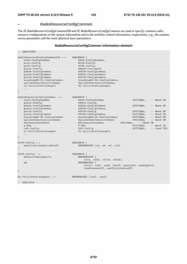
ETSI
ETSI TS 136 331 V9.12.0 (2012-11)1533GPP TS 36.331 version 9.12.0 Release 9
– RadioResourceConfigCommon
The IE RadioResourceConfigCommonSIB and IE RadioResourceConfigCommon are used to specify common radio resource configurations in the system information and in the mobility control information, respectively, e.g., the random access parameters and the static physical layer parameters.
RadioResourceConfigCommon information element
-- ASN1START RadioResourceConfigCommonSIB ::= SEQUENCE { rach-ConfigCommon RACH-ConfigCommon, bcch-Config BCCH-Config, pcch-Config PCCH-Config, prach-Config PRACH-ConfigSIB, pdsch-ConfigCommon PDSCH-ConfigCommon, pusch-ConfigCommon PUSCH-ConfigCommon, pucch-ConfigCommon PUCCH-ConfigCommon, soundingRS-UL-ConfigCommon SoundingRS-UL-ConfigCommon, uplinkPowerControlCommon UplinkPowerControlCommon, ul-CyclicPrefixLength UL-CyclicPrefixLength, ... } RadioResourceConfigCommon ::= SEQUENCE { rach-ConfigCommon RACH-ConfigCommon OPTIONAL, -- Need ON prach-Config PRACH-Config, pdsch-ConfigCommon PDSCH-ConfigCommon OPTIONAL, -- Need ON pusch-ConfigCommon PUSCH-ConfigCommon, phich-Config PHICH-Config OPTIONAL, -- Need ON pucch-ConfigCommon PUCCH-ConfigCommon OPTIONAL, -- Need ON soundingRS-UL-ConfigCommon SoundingRS-UL-ConfigCommon OPTIONAL, -- Need ON uplinkPowerControlCommon UplinkPowerControlCommon OPTIONAL, -- Need ON antennaInfoCommon AntennaInfoCommon OPTIONAL, -- Need ON p-Max P-Max OPTIONAL, -- Need OP tdd-Config TDD-Config OPTIONAL, -- Cond TDD ul-CyclicPrefixLength UL-CyclicPrefixLength, ... } BCCH-Config ::= SEQUENCE { modificationPeriodCoeff ENUMERATED {n2, n4, n8, n16} } PCCH-Config ::= SEQUENCE { defaultPagingCycle ENUMERATED { rf32, rf64, rf128, rf256}, nB ENUMERATED { fourT, twoT, oneT, halfT, quarterT, oneEighthT, oneSixteenthT, oneThirtySecondT} } UL-CyclicPrefixLength ::= ENUMERATED {len1, len2} -- ASN1STOP

ETSI
ETSI TS 136 331 V9.12.0 (2012-11)1543GPP TS 36.331 version 9.12.0 Release 9
RadioResourceConfigCommon field descriptions p-Max Pmax to be used in the target cell. If absent the UE applies the maximum power according to the UE capability. modificationPeriodCoeff Actual modification period, expressed in number of radio frames= modificationPeriodCoeff * defaultPagingCycle. n2 corresponds to value 2, n4 corresponds to value 4, n8 corresponds to value 8 and n16 corresponds to value 16. defaultPagingCycle Default paging cycle, used to derive ‘T’ in TS 36.304 [4]. Value rf32 corresponds to 32 radio frames, rf64 corresponds to 64 radio frames and so on. nB Parameter: nB is used as one of parameters to derive the Paging Frame and Paging Occasion according to TS 36.304 [4]. Value in multiples of defaultPagingCycle ('T'). A value of fourT corresponds to 4 * defaultPagingCycle, a value of twoT corresponds to 2 * defaultPagingCycle and so on. UL-CyclicPrefixLength Parameter: Uplink cyclic prefix length see 36.211 [21, 5.2.1] where len1 corresponds to normal cyclic prefix and len2 corresponds to extended cyclic prefix.
Conditional presence Explanation TDD The field is optional for TDD, Need ON; it is not present for FDD and the UE shall delete
any existing value for this field.
– RadioResourceConfigDedicated
The IE RadioResourceConfigDedicated is used to setup/modify/release RBs, to modify the MAC main configuration, to modify the SPS configuration and to modify dedicated physical configuration.
RadioResourceConfigDedicated information element
-- ASN1START RadioResourceConfigDedicated ::= SEQUENCE { srb-ToAddModList SRB-ToAddModList OPTIONAL, -- Cond HO-Conn drb-ToAddModList DRB-ToAddModList OPTIONAL, -- Cond HO-toEUTRA drb-ToReleaseList DRB-ToReleaseList OPTIONAL, -- Need ON mac-MainConfig CHOICE { explicitValue MAC-MainConfig, defaultValue NULL } OPTIONAL, -- Cond HO-toEUTRA2 sps-Config SPS-Config OPTIONAL, -- Need ON physicalConfigDedicated PhysicalConfigDedicated OPTIONAL, -- Need ON ..., [[ rlf-TimersAndConstants-r9 RLF-TimersAndConstants-r9 OPTIONAL -- Need ON ]] } SRB-ToAddModList ::= SEQUENCE (SIZE (1..2)) OF SRB-ToAddMod SRB-ToAddMod ::= SEQUENCE { srb-Identity INTEGER (1..2), rlc-Config CHOICE { explicitValue RLC-Config, defaultValue NULL } OPTIONAL, -- Cond Setup logicalChannelConfig CHOICE { explicitValue LogicalChannelConfig, defaultValue NULL } OPTIONAL, -- Cond Setup ... } DRB-ToAddModList ::= SEQUENCE (SIZE (1..maxDRB)) OF DRB-ToAddMod DRB-ToAddMod ::= SEQUENCE { eps-BearerIdentity INTEGER (0..15) OPTIONAL, -- Cond DRB-Setup drb-Identity DRB-Identity, pdcp-Config PDCP-Config OPTIONAL, -- Cond PDCP rlc-Config RLC-Config OPTIONAL, -- Cond Setup logicalChannelIdentity INTEGER (3..10) OPTIONAL, -- Cond DRB-Setup
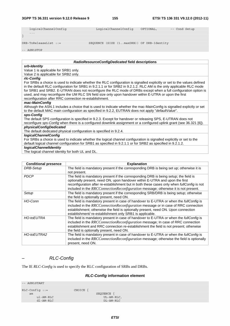
ETSI
ETSI TS 136 331 V9.12.0 (2012-11)1553GPP TS 36.331 version 9.12.0 Release 9
logicalChannelConfig LogicalChannelConfig OPTIONAL, -- Cond Setup ... } DRB-ToReleaseList ::= SEQUENCE (SIZE (1..maxDRB)) OF DRB-Identity -- ASN1STOP
RadioResourceConfigDedicated field descriptions srb-Identity Value 1 is applicable for SRB1 only. Value 2 is applicable for SRB2 only. rlc-Config For SRBs a choice is used to indicate whether the RLC configuration is signalled explicitly or set to the values defined in the default RLC configuration for SRB1 in 9.2.1.1 or for SRB2 in 9.2.1.2. RLC AM is the only applicable RLC mode for SRB1 and SRB2. E-UTRAN does not reconfigure the RLC mode of DRBs except when a full configuration option is used, and may reconfigure the UM RLC SN field size only upon handover within E-UTRA or upon the first reconfiguration after RRC connection re-establishment. mac-MainConfig Although the ASN.1 includes a choice that is used to indicate whether the mac-MainConfig is signalled explictly or set to the default MAC main configuration as specified in 9.2.2, EUTRAN does not apply "defaultValue". sps-Config The default SPS configuration is specified in 9.2.3. Except for handover or releasing SPS, E-UTRAN does not reconfigure sps-Config when there is a configured downlink assignment or a configured uplink grant (see 36.321 [6]). physicalConfigDedicated The default dedicated physical configuration is specified in 9.2.4. logicalChannelConfig For SRBs a choice is used to indicate whether the logical channel configuration is signalled explicitly or set to the default logical channel configuration for SRB1 as specified in 9.2.1.1 or for SRB2 as specified in 9.2.1.2. logicalChannelIdentity The logical channel identity for both UL and DL.
Conditional presence Explanation DRB-Setup The field is mandatory present if the corresponding DRB is being set up; otherwise it is
not present. PDCP The field is mandatory present if the corresponding DRB is being setup; the field is
optionally present, need ON, upon handover within E-UTRA and upon the first reconfiguration after re-establishment but in both these cases only when fullConfig is not included in the RRCConnectionReconfiguration message; otherwise it is not present.
Setup The field is mandatory present if the corresponding SRB/DRB is being setup; otherwise the field is optionally present, need ON.
HO-Conn The field is mandatory present in case of handover to E-UTRA or when the fullConfig is included in the RRCConnectionReconfiguration message or in case of RRC connection establishment; otherwise the field is optionally present, need ON. Upon connection establishment/ re-establishment only SRB1 is applicable.
HO-toEUTRA The field is mandatory present in case of handover to E-UTRA or when the fullConfig is included in the RRCConnectionReconfiguration message; In case of RRC connection establishment and RRC connection re-establishment the field is not present; otherwise the field is optionally present, need ON.
HO-toEUTRA2 The field is mandatory present in case of handover to E-UTRA or when the fullConfig is included in the RRCConnectionReconfiguration message; otherwise the field is optionally present, need ON.
– RLC-Config
The IE RLC-Config is used to specify the RLC configuration of SRBs and DRBs.
RLC-Config information element
-- ASN1START RLC-Config ::= CHOICE { am SEQUENCE { ul-AM-RLC UL-AM-RLC, dl-AM-RLC DL-AM-RLC
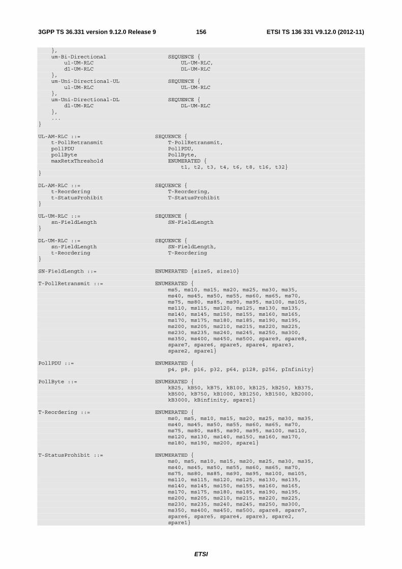
ETSI
ETSI TS 136 331 V9.12.0 (2012-11)1563GPP TS 36.331 version 9.12.0 Release 9
}, um-Bi-Directional SEQUENCE { ul-UM-RLC UL-UM-RLC, dl-UM-RLC DL-UM-RLC }, um-Uni-Directional-UL SEQUENCE { ul-UM-RLC UL-UM-RLC }, um-Uni-Directional-DL SEQUENCE { dl-UM-RLC DL-UM-RLC }, ... } UL-AM-RLC ::= SEQUENCE { t-PollRetransmit T-PollRetransmit, pollPDU PollPDU, pollByte PollByte, maxRetxThreshold ENUMERATED { t1, t2, t3, t4, t6, t8, t16, t32} } DL-AM-RLC ::= SEQUENCE { t-Reordering T-Reordering, t-StatusProhibit T-StatusProhibit } UL-UM-RLC ::= SEQUENCE { sn-FieldLength SN-FieldLength } DL-UM-RLC ::= SEQUENCE { sn-FieldLength SN-FieldLength, t-Reordering T-Reordering } SN-FieldLength ::= ENUMERATED {size5, size10} T-PollRetransmit ::= ENUMERATED { ms5, ms10, ms15, ms20, ms25, ms30, ms35, ms40, ms45, ms50, ms55, ms60, ms65, ms70, ms75, ms80, ms85, ms90, ms95, ms100, ms105, ms110, ms115, ms120, ms125, ms130, ms135, ms140, ms145, ms150, ms155, ms160, ms165, ms170, ms175, ms180, ms185, ms190, ms195, ms200, ms205, ms210, ms215, ms220, ms225, ms230, ms235, ms240, ms245, ms250, ms300, ms350, ms400, ms450, ms500, spare9, spare8, spare7, spare6, spare5, spare4, spare3, spare2, spare1} PollPDU ::= ENUMERATED { p4, p8, p16, p32, p64, p128, p256, pInfinity} PollByte ::= ENUMERATED { kB25, kB50, kB75, kB100, kB125, kB250, kB375, kB500, kB750, kB1000, kB1250, kB1500, kB2000, kB3000, kBinfinity, spare1} T-Reordering ::= ENUMERATED { ms0, ms5, ms10, ms15, ms20, ms25, ms30, ms35, ms40, ms45, ms50, ms55, ms60, ms65, ms70, ms75, ms80, ms85, ms90, ms95, ms100, ms110, ms120, ms130, ms140, ms150, ms160, ms170, ms180, ms190, ms200, spare1} T-StatusProhibit ::= ENUMERATED { ms0, ms5, ms10, ms15, ms20, ms25, ms30, ms35, ms40, ms45, ms50, ms55, ms60, ms65, ms70, ms75, ms80, ms85, ms90, ms95, ms100, ms105, ms110, ms115, ms120, ms125, ms130, ms135, ms140, ms145, ms150, ms155, ms160, ms165, ms170, ms175, ms180, ms185, ms190, ms195, ms200, ms205, ms210, ms215, ms220, ms225, ms230, ms235, ms240, ms245, ms250, ms300, ms350, ms400, ms450, ms500, spare8, spare7, spare6, spare5, spare4, spare3, spare2, spare1}

ETSI
ETSI TS 136 331 V9.12.0 (2012-11)1573GPP TS 36.331 version 9.12.0 Release 9
-- ASN1STOP
RLC-Config field descriptions sn-FieldLength Indicates the UM RLC SN field size, see TS 36.322 [7], in bits. Value size5 means 5 bits, size10 means 10 bits. t-PollRetransmit Timer for RLC AM in TS 36.322 [7], in milliseconds. Value ms5 means 5ms, ms10 means 10ms and so on. pollPDU Parameter for RLC AM in TS 36.322 [7]. Value p4 corresponds to 4 PDUs, p8 to 8 PDUs and so on. pInfinity corresponds to an infinite number of PDUs. pollByte Parameter for RLC AM in TS 36.322 [7]. Value kB25 corresponds to 25 kBytes, kB50 to 50 kBytes and so on. kBInfinity corresponds to an infinite amount of kBytes. maxRetxThreshold Parameter for RLC AM in TS 36.322 [7]. Value t1 corresponds to 1 retransmission, t2 to 2 retransmissions and so on. t-Reordering Timer for reordering in TS 36.322 [7], in milliseconds. Value ms0 means 0ms, ms5 means 5ms and so on. t-StatusProhibit Timer for status reporting in TS 36.322 [7], in milliseconds. Value ms0 means 0ms, ms5 means 5ms and so on.
– RLF-TimersAndConstants
The IE RLF-TimersAndConstants contains UE specific timers and constants applicable for UEs in RRC_CONNECTED.
RLF-TimersAndConstants information element
-- ASN1START RLF-TimersAndConstants-r9 ::= CHOICE { release NULL, setup SEQUENCE { t301-r9 ENUMERATED { ms100, ms200, ms300, ms400, ms600, ms1000, ms1500, ms2000}, t310-r9 ENUMERATED { ms0, ms50, ms100, ms200, ms500, ms1000, ms2000}, n310-r9 ENUMERATED { n1, n2, n3, n4, n6, n8, n10, n20}, t311-r9 ENUMERATED { ms1000, ms3000, ms5000, ms10000, ms15000, ms20000, ms30000}, n311-r9 ENUMERATED { n1, n2, n3, n4, n5, n6, n8, n10}, ... } } -- ASN1STOP
RLF-TimersAndConstants field descriptions t3xy Timers are described in section 7.3. Value ms0 corresponds with 0 ms, ms50 corresponds with 50 ms and so on. n3xy Constants are described in section 7.4. n1 corresponds with 1, n2 corresponds with 2 and so on.
– SchedulingRequestConfig
The IE SchedulingRequestConfig is used to specify the Scheduling Request related parameters
SchedulingRequestConfig information element
-- ASN1START

ETSI
ETSI TS 136 331 V9.12.0 (2012-11)1583GPP TS 36.331 version 9.12.0 Release 9
SchedulingRequestConfig ::= CHOICE { release NULL, setup SEQUENCE { sr-PUCCH-ResourceIndex INTEGER (0..2047), sr-ConfigIndex INTEGER (0..157), dsr-TransMax ENUMERATED { n4, n8, n16, n32, n64, spare3, spare2, spare1} } } -- ASN1STOP
SchedulingRequestConfig field descriptions sr-PUCCH-ResourceIndex
Parameter: )1(
SRIPUCCH,n . see TS 36.213 [23, 10.1].
sr-ConfigIndex Parameter SRI . See TS 36.213 [23,10.1]. The values 156 and 157 are not applicable for Release 8.
dsr-TransMax Parameter for SR transmission in TS 36.321 [6, 5.4.4]. The value n4 corresponds to 4 transmissions, n8 corresponds to 8 transmissions and so on.
– SoundingRS-UL-Config
The IE SoundingRS-UL-Config is used to specify the uplink Sounding RS configuration.
SoundingRS-UL-Config information element
-- ASN1START SoundingRS-UL-ConfigCommon ::= CHOICE { release NULL, setup SEQUENCE { srs-BandwidthConfig ENUMERATED {bw0, bw1, bw2, bw3, bw4, bw5, bw6, bw7}, srs-SubframeConfig ENUMERATED { sc0, sc1, sc2, sc3, sc4, sc5, sc6, sc7, sc8, sc9, sc10, sc11, sc12, sc13, sc14, sc15}, ackNackSRS-SimultaneousTransmission BOOLEAN, srs-MaxUpPts ENUMERATED {true} OPTIONAL -- Cond TDD } } SoundingRS-UL-ConfigDedicated ::= CHOICE{ release NULL, setup SEQUENCE { srs-Bandwidth ENUMERATED {bw0, bw1, bw2, bw3}, srs-HoppingBandwidth ENUMERATED {hbw0, hbw1, hbw2, hbw3}, freqDomainPosition INTEGER (0..23), duration BOOLEAN, srs-ConfigIndex INTEGER (0..1023), transmissionComb INTEGER (0..1), cyclicShift ENUMERATED {cs0, cs1, cs2, cs3, cs4, cs5, cs6, cs7} } } -- ASN1STOP

ETSI
ETSI TS 136 331 V9.12.0 (2012-11)1593GPP TS 36.331 version 9.12.0 Release 9
SoundingRS-UL-Config field descriptions srs-BandwidthConfig Parameter: SRS Bandwidth Configuration. See TS 36.211, [21, table 5.5.3.2-1, 5.5.3.2-2, 5.5.3.2-3 and 5.5.3.2– 4]. Actual configuration depends on UL bandwidth. bw0 corresponds to value 0, bw1 to value 1 and so on. srs-SubframeConfig Parameter: SRS SubframeConfiguration. See TS 36.211, [21, table 5.5.3.3-1] applies for FDD whereas TS 36.211, [21, table 5.5.3.3-2] applies for TDD. sc0 corresponds to value 0, sc1 to value 1 and so on. ackNackSRS-SimultaneousTransmission Parameter: Simultaneous-AN-and-SRS, see TS 36.213 [23, 8.2]. srs-Bandwidth Parameter: SRSB , see TS 36.211 [21, tables 5.5.3.2-1, 5.5.3.2-2, 5.5.3.2-3 and 5.5.3.2-4].
freqDomainPosition Parameter: RRCn , see TS 36.211 [21, 5.5.3.2].
srs-HoppingBandwidth
Parameter: SRS hopping bandwidth }3,2,1,0{∈hopb , see TS 36.211 [21, 5.5.3.2] where hbw0 corresponds to value
0, hbw1 to value 1 and so on. duration Parameter: Duration. See TS 36.213 [21, 8.2]. FALSE corresponds to “single” and value TRUE to “indefinite”. srs-ConfigIndex Parameter: ISRS. See TS 36.213 [23, table8.2-1]. transmissionComb
Parameter: }1,0{TC ∈k , see TS 36.211 [21, 5.5.3.2].
cyclicShift Parameter: n_SRS. See TS 36.211 [21, 5.5.3.1], where cs0 corresponds to 0 etc. srs-MaxUpPts
Parameter: srsMaxUpPts, see TS 36.211 [21, 5.5.3.2]. If this field is present, reconfiguration of max
0,SRSm applies for
UpPts, otherwise reconfiguration does not apply.
Conditional presence Explanation TDD This field is optional present for TDD, need OR; it is not present for FDD and the UE shall
delete any existing value for this field.
– SPS-Config
The IE SPS-Config is used to specify the semi-persistent scheduling configuration.
SPS-Config information element
-- ASN1START SPS-Config ::= SEQUENCE { semiPersistSchedC-RNTI C-RNTI OPTIONAL, -- Need OR sps-ConfigDL SPS-ConfigDL OPTIONAL, -- Need ON sps-ConfigUL SPS-ConfigUL OPTIONAL -- Need ON } SPS-ConfigDL ::= CHOICE{ release NULL, setup SEQUENCE { semiPersistSchedIntervalDL ENUMERATED { sf10, sf20, sf32, sf40, sf64, sf80, sf128, sf160, sf320, sf640, spare6, spare5, spare4, spare3, spare2, spare1}, numberOfConfSPS-Processes INTEGER (1..8), n1-PUCCH-AN-PersistentList N1-PUCCH-AN-PersistentList, ... } } SPS-ConfigUL ::= CHOICE { release NULL, setup SEQUENCE { semiPersistSchedIntervalUL ENUMERATED {

ETSI
ETSI TS 136 331 V9.12.0 (2012-11)1603GPP TS 36.331 version 9.12.0 Release 9
sf10, sf20, sf32, sf40, sf64, sf80, sf128, sf160, sf320, sf640, spare6, spare5, spare4, spare3, spare2, spare1}, implicitReleaseAfter ENUMERATED {e2, e3, e4, e8}, p0-Persistent SEQUENCE { p0-NominalPUSCH-Persistent INTEGER (-126..24), p0-UE-PUSCH-Persistent INTEGER (-8..7) } OPTIONAL, -- Need OP twoIntervalsConfig ENUMERATED {true} OPTIONAL, -- Cond TDD ... } } N1-PUCCH-AN-PersistentList ::= SEQUENCE (SIZE (1..4)) OF INTEGER (0..2047) -- ASN1STOP
SPS-Config field descriptions semiPersistSchedC-RNTI Semi-persistent Scheduling C-RNTI, see TS 36.321 [6]. semiPersistSchedIntervalDL Semi-persistent scheduling interval in downlink, see TS 36.321 [6]. Value in number of sub-frames. Value sf10 corresponds to 10 sub-frames, sf20 corresponds to 20 sub-frames and so on. For TDD, the UE shall round this parameter down to the nearest integer (of 10 sub-frames), e.g. sf10 corresponds to 10 sub-frames, sf32 corresponds to 30 sub-frames, sf128 corresponds to 120 sub-frames. In this release, sf32, sf64 and sf128 should not be configured in TDD. numberOfConfSPS-Processes The number of configured HARQ processes for Semi-Persistent Scheduling, see TS 36.321 [6]. n1-PUCCH-AN-PersistentList
List of parameter: )1(PUCCHn see TS 36.213, [23, 10.1].
semiPersistSchedIntervalUL Semi-persistent scheduling interval in uplink, see TS 36.321 [6]. Value in number of sub-frames. Value sf10 corresponds to 10 sub-frames, sf20 corresponds to 20 sub-frames and so on. For TDD, the UE shall round this parameter down to the nearest integer (of 10 sub-frames), e.g. sf10 corresponds to 10 sub-frames, sf32 corresponds to 30 sub-frames, sf128 corresponds to 120 sub-frames. In this release, sf32, sf64 and sf128 should not be configured in TDD. implicitReleaseAfter Number of empty transmissions before implicit release, see TS 36.321 [6, 5.10.2]. Value e2 corresponds to 2 transmissions, e3 corresponds to 3 transmissions and so on. p0-NominalPUSCH-Persistent Parameter: )0( PUSCHO_NOMINAL_P . See TS 36.213 [23, 5.1.1.1], unit dBm step 1. This field is applicable for persistent
scheduling, only. If choice ‘setup’ is used and p0-Persistent is absent, apply the value of p0-NominalPUSCH for p0-NominalPUSCH-Persistent. p0-UE-PUSCH-Persistent Parameter: )0(O_UE_PUSCHP . See TS 36.213 [23, 5.1.1.1], unit dB. This field is applicable for persistent scheduling,
only. If choice ‘setup’ is used and p0-Persistent is absent, apply the value of p0-UE-PUSCH for p0-UE-PUSCH-Persistent. twoIntervalsConfig Trigger of two-intervals-Semi-Persistent Scheduling in uplink. See TS 36.321 [6, 5.10]. If this field is present, two-intervals-SPS is enabled for uplink. Otherwise, two-intervals-SPS is disabled.
Conditional presence Explanation TDD This field is optional present for TDD, need OR; it is not present for FDD and the UE shall
delete any existing value for this field.
– TDD-Config
The IE TDD-Config is used to specify the TDD specific physical channel configuration.
TDD-Config information element
-- ASN1START
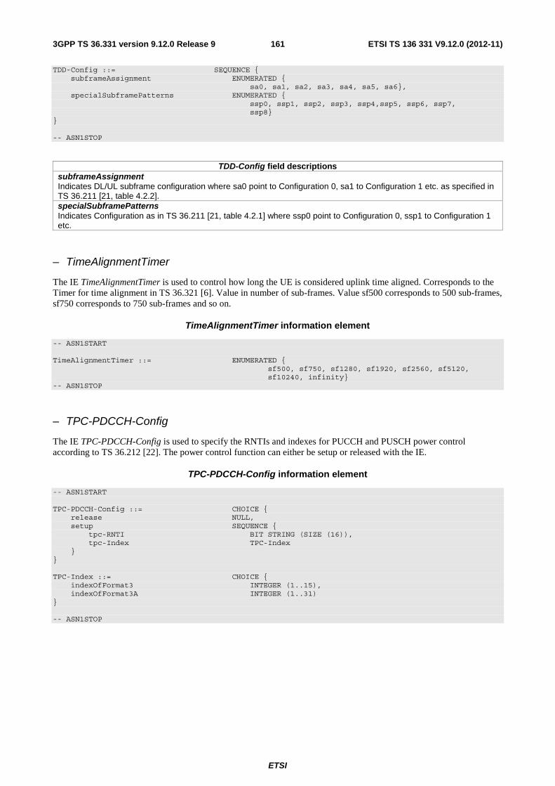
ETSI
ETSI TS 136 331 V9.12.0 (2012-11)1613GPP TS 36.331 version 9.12.0 Release 9
TDD-Config ::= SEQUENCE { subframeAssignment ENUMERATED { sa0, sa1, sa2, sa3, sa4, sa5, sa6}, specialSubframePatterns ENUMERATED { ssp0, ssp1, ssp2, ssp3, ssp4,ssp5, ssp6, ssp7, ssp8} } -- ASN1STOP
TDD-Config field descriptions subframeAssignment Indicates DL/UL subframe configuration where sa0 point to Configuration 0, sa1 to Configuration 1 etc. as specified in TS 36.211 [21, table 4.2.2]. specialSubframePatterns Indicates Configuration as in TS 36.211 [21, table 4.2.1] where ssp0 point to Configuration 0, ssp1 to Configuration 1 etc.
– TimeAlignmentTimer
The IE TimeAlignmentTimer is used to control how long the UE is considered uplink time aligned. Corresponds to the Timer for time alignment in TS 36.321 [6]. Value in number of sub-frames. Value sf500 corresponds to 500 sub-frames, sf750 corresponds to 750 sub-frames and so on.
TimeAlignmentTimer information element
-- ASN1START TimeAlignmentTimer ::= ENUMERATED { sf500, sf750, sf1280, sf1920, sf2560, sf5120, sf10240, infinity} -- ASN1STOP
– TPC-PDCCH-Config
The IE TPC-PDCCH-Config is used to specify the RNTIs and indexes for PUCCH and PUSCH power control according to TS 36.212 [22]. The power control function can either be setup or released with the IE.
TPC-PDCCH-Config information element
-- ASN1START TPC-PDCCH-Config ::= CHOICE { release NULL, setup SEQUENCE { tpc-RNTI BIT STRING (SIZE (16)), tpc-Index TPC-Index } } TPC-Index ::= CHOICE { indexOfFormat3 INTEGER (1..15), indexOfFormat3A INTEGER (1..31) } -- ASN1STOP

ETSI
ETSI TS 136 331 V9.12.0 (2012-11)1623GPP TS 36.331 version 9.12.0 Release 9
TPC-PDCCH-Config field descriptions tpc-RNTI RNTI for power control using DCI format 3/3A, see TS 36.212 [22]. tpc-Index Index of N or M, see TS 36.212 [22, 5.3.3.1.6 and 5.3.3.1.7], where N or M is dependent on the used DCI format (i.e. format 3 or 3a). indexOfFormat3 Index of N when DCI format 3 is used. See TS 36.212 [22, 5.3.3.1.6]. IndexOfFormat3A Index of M when DCI format 3A is used. See TS 36.212 [22, 5.3.3.1.7].
– UplinkPowerControl
The IE UplinkPowerControlCommon and IE UplinkPowerControlDedicated are used to specify parameters for uplink power control in the system information and in the dedicated signalling, respectively.
UplinkPowerControl information elements
-- ASN1START UplinkPowerControlCommon ::= SEQUENCE { p0-NominalPUSCH INTEGER (-126..24), alpha ENUMERATED {al0, al04, al05, al06, al07, al08, al09, al1}, p0-NominalPUCCH INTEGER (-127..-96), deltaFList-PUCCH DeltaFList-PUCCH, deltaPreambleMsg3 INTEGER (-1..6) } UplinkPowerControlDedicated ::= SEQUENCE { p0-UE-PUSCH INTEGER (-8..7), deltaMCS-Enabled ENUMERATED {en0, en1}, accumulationEnabled BOOLEAN, p0-UE-PUCCH INTEGER (-8..7), pSRS-Offset INTEGER (0..15), filterCoefficient FilterCoefficient DEFAULT fc4 } DeltaFList-PUCCH ::= SEQUENCE { deltaF-PUCCH-Format1 ENUMERATED {deltaF-2, deltaF0, deltaF2}, deltaF-PUCCH-Format1b ENUMERATED {deltaF1, deltaF3, deltaF5}, deltaF-PUCCH-Format2 ENUMERATED {deltaF-2, deltaF0, deltaF1, deltaF2}, deltaF-PUCCH-Format2a ENUMERATED {deltaF-2, deltaF0, deltaF2}, deltaF-PUCCH-Format2b ENUMERATED {deltaF-2, deltaF0, deltaF2} } -- ASN1STOP
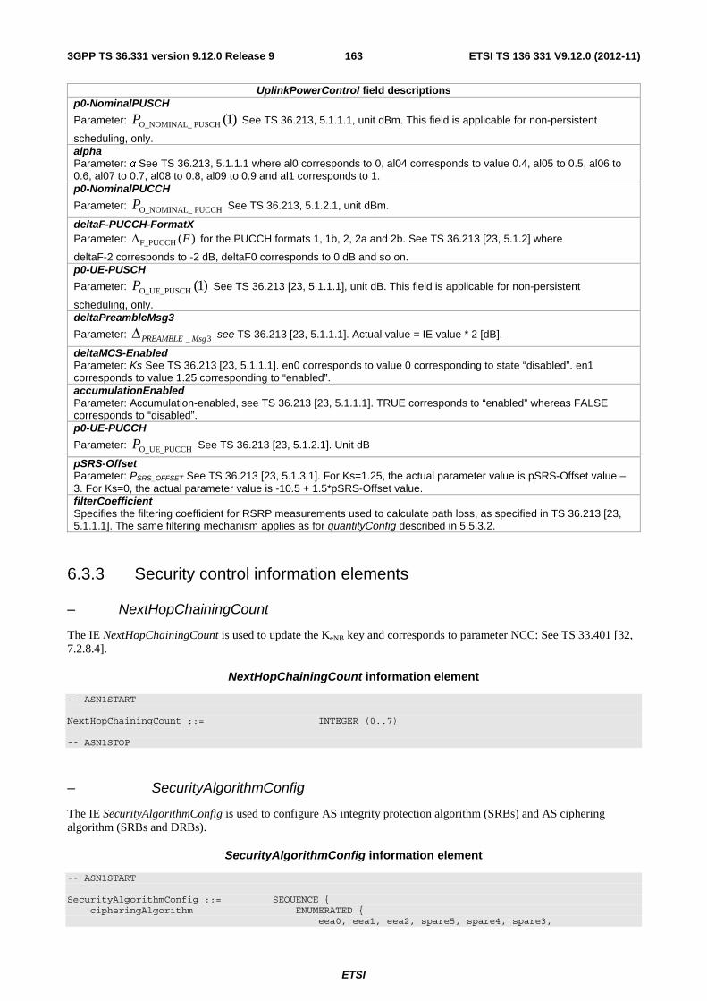
ETSI
ETSI TS 136 331 V9.12.0 (2012-11)1633GPP TS 36.331 version 9.12.0 Release 9
UplinkPowerControl field descriptions p0-NominalPUSCH
Parameter: )1(PUSCH O_NOMINAL_P See TS 36.213, 5.1.1.1, unit dBm. This field is applicable for non-persistent
scheduling, only. alpha Parameter: α See TS 36.213, 5.1.1.1 where al0 corresponds to 0, al04 corresponds to value 0.4, al05 to 0.5, al06 to 0.6, al07 to 0.7, al08 to 0.8, al09 to 0.9 and al1 corresponds to 1. p0-NominalPUCCH
Parameter: PUCCH O_NOMINAL_P See TS 36.213, 5.1.2.1, unit dBm.
deltaF-PUCCH-FormatX Parameter: F_PUCCH ( )FΔ for the PUCCH formats 1, 1b, 2, 2a and 2b. See TS 36.213 [23, 5.1.2] where
deltaF-2 corresponds to -2 dB, deltaF0 corresponds to 0 dB and so on. p0-UE-PUSCH
Parameter: )1(O_UE_PUSCHP See TS 36.213 [23, 5.1.1.1], unit dB. This field is applicable for non-persistent
scheduling, only. deltaPreambleMsg3
Parameter: 3_ MsgPREAMBLEΔ see TS 36.213 [23, 5.1.1.1]. Actual value = IE value * 2 [dB].
deltaMCS-Enabled Parameter: Ks See TS 36.213 [23, 5.1.1.1]. en0 corresponds to value 0 corresponding to state “disabled”. en1 corresponds to value 1.25 corresponding to “enabled”. accumulationEnabled Parameter: Accumulation-enabled, see TS 36.213 [23, 5.1.1.1]. TRUE corresponds to “enabled” whereas FALSE corresponds to “disabled”. p0-UE-PUCCH
Parameter: O_UE_PUCCHP See TS 36.213 [23, 5.1.2.1]. Unit dB
pSRS-Offset Parameter: PSRS_OFFSET See TS 36.213 [23, 5.1.3.1]. For Ks=1.25, the actual parameter value is pSRS-Offset value – 3. For Ks=0, the actual parameter value is -10.5 + 1.5*pSRS-Offset value. filterCoefficient Specifies the filtering coefficient for RSRP measurements used to calculate path loss, as specified in TS 36.213 [23, 5.1.1.1]. The same filtering mechanism applies as for quantityConfig described in 5.5.3.2.
6.3.3 Security control information elements
– NextHopChainingCount
The IE NextHopChainingCount is used to update the KeNB key and corresponds to parameter NCC: See TS 33.401 [32, 7.2.8.4].
NextHopChainingCount information element
-- ASN1START NextHopChainingCount ::= INTEGER (0..7) -- ASN1STOP
– SecurityAlgorithmConfig
The IE SecurityAlgorithmConfig is used to configure AS integrity protection algorithm (SRBs) and AS ciphering algorithm (SRBs and DRBs).
SecurityAlgorithmConfig information element
-- ASN1START SecurityAlgorithmConfig ::= SEQUENCE { cipheringAlgorithm ENUMERATED { eea0, eea1, eea2, spare5, spare4, spare3,

ETSI
ETSI TS 136 331 V9.12.0 (2012-11)1643GPP TS 36.331 version 9.12.0 Release 9
spare2, spare1, ...}, integrityProtAlgorithm ENUMERATED { eia0-v920, eia1, eia2, spare5, spare4, spare3, spare2, spare1, ...} } -- ASN1STOP
SecurityAlgorithmConfig field descriptions integrityProtAlgorithm Indicates the integrity protection algorithm to be used for SRBs, as specified in TS 33.401 [32, 5.1.4.2]. cipheringAlgorithm Indicates the ciphering algorithm to be used for SRBs and DRBs, as specified in TS 33.401 [32, 5.1.3.2].
– ShortMAC-I
The IE ShortMAC-I is used to identify and verify the UE at RRC connection re-establishment. The 16 least significant bits of the MAC-I calculated using the security configuration of the source cell, as specified in 5.3.7.4.
ShortMAC-I information element
-- ASN1START ShortMAC-I ::= BIT STRING (SIZE (16)) -- ASN1STOP
6.3.4 Mobility control information elements
– AdditionalSpectrumEmission
The UE requirements related to IE AdditionalSpectrumEmission are defined in TS 36.101 [42, table 6.2.4-1].
AdditionalSpectrumEmission information element
-- ASN1START AdditionalSpectrumEmission ::= INTEGER (1..32) -- ASN1STOP
– ARFCN-ValueCDMA2000
The IE ARFCN-ValueCDMA2000 used to indicate the CDMA2000 carrier frequency within a CDMA2000 band, see C.S0002-A [12].
ARFCN-ValueCDMA2000 information element
-- ASN1START ARFCN-ValueCDMA2000 ::= INTEGER (0..2047) -- ASN1STOP
– ARFCN-ValueEUTRA
The IE ARFCN-ValueEUTRA is used to indicate the ARFCN applicable for a downlink, uplink or bi-directional (TDD) E-UTRA carrier frequency, as defined in TS 36.101 [42].
ARFCN-ValueEUTRA information element
-- ASN1START

ETSI
ETSI TS 136 331 V9.12.0 (2012-11)1653GPP TS 36.331 version 9.12.0 Release 9
ARFCN-ValueEUTRA ::= INTEGER (0..maxEARFCN) -- ASN1STOP
– ARFCN-ValueGERAN
The IE ARFCN-ValueGERAN is used to specify the ARFCN value applicable for a GERAN BCCH carrier frequency, see TS 45.005 [20].
ARFCN-ValueGERAN information element
-- ASN1START ARFCN-ValueGERAN ::= INTEGER (0..1023) -- ASN1STOP
– ARFCN-ValueUTRA
The IE ARFCN-ValueUTRA is used to indicate the ARFCN applicable for a downlink (Nd, FDD) or bi-directional (Nt, TDD) UTRA carrier frequency, as defined in TS 25.331 [19].
ARFCN-ValueUTRA information element
-- ASN1START ARFCN-ValueUTRA ::= INTEGER (0..16383) -- ASN1STOP
– BandclassCDMA2000
The IE BandclassCDMA2000 is used to define the CDMA2000 band in which the CDMA2000 carrier frequency can be found, as defined in C.S0057-E [24, table 1.5-1].
BandclassCDMA2000 information element
-- ASN1START BandclassCDMA2000 ::= ENUMERATED { bc0, bc1, bc2, bc3, bc4, bc5, bc6, bc7, bc8, bc9, bc10, bc11, bc12, bc13, bc14, bc15, bc16, bc17, bc18-v9a0, bc19-v9a0, bc20-v9a0, bc21-v9a0, spare10, spare9, spare8, spare7, spare6, spare5, spare4, spare3, spare2, spare1, ...} -- ASN1STOP
– BandIndicatorGERAN
The IE BandIndicatorGERAN indicates how to interpret an associated GERAN carrier ARFCN, see TS 45.005 [20]. More specifically, the IE indicates the GERAN frequency band in case the ARFCN value can concern either a DCS 1800 or a PCS 1900 carrier frequency. For ARFCN values not associated with one of these bands, the indicator has no meaning.
BandIndicatorGERAN information element
-- ASN1START BandIndicatorGERAN ::= ENUMERATED {dcs1800, pcs1900} -- ASN1STOP

ETSI
ETSI TS 136 331 V9.12.0 (2012-11)1663GPP TS 36.331 version 9.12.0 Release 9
– CarrierFreqCDMA2000
The IE CarrierFreqCDMA2000 used to provide the CDMA2000 carrier information.
CarrierFreqCDMA2000 information element
-- ASN1START CarrierFreqCDMA2000 ::= SEQUENCE { bandClass BandclassCDMA2000, arfcn ARFCN-ValueCDMA2000 } -- ASN1STOP
– CarrierFreqGERAN
The IE CarrierFreqGERAN is used to provide an unambiguous carrier frequency description of a GERAN cell.
CarrierFreqGERAN information element
-- ASN1START CarrierFreqGERAN ::= SEQUENCE { arfcn ARFCN-ValueGERAN, bandIndicator BandIndicatorGERAN } -- ASN1STOP
CarrierFreqGERAN field descriptions arfcn GERAN ARFCN of BCCH carrier. bandIndicator Indicates how to interpret the ARFCN of the BCCH carrier.
– CarrierFreqsGERAN
The IE CarrierFreqListGERAN is used to provide one or more GERAN ARFCN values, as defined in TS 44.005 [43], which represents a list of GERAN BCCH carrier frequencies.
CarrierFreqsGERAN information element
-- ASN1START CarrierFreqsGERAN ::= SEQUENCE { startingARFCN ARFCN-ValueGERAN, bandIndicator BandIndicatorGERAN, followingARFCNs CHOICE { explicitListOfARFCNs ExplicitListOfARFCNs, equallySpacedARFCNs SEQUENCE { arfcn-Spacing INTEGER (1..8), numberOfFollowingARFCNs INTEGER (0..31) }, variableBitMapOfARFCNs OCTET STRING (SIZE (1..16)) } } ExplicitListOfARFCNs ::= SEQUENCE (SIZE (0..31)) OF ARFCN-ValueGERAN -- ASN1STOP

ETSI
ETSI TS 136 331 V9.12.0 (2012-11)1673GPP TS 36.331 version 9.12.0 Release 9
CarrierFreqsGERAN field descriptions startingARFCN The first ARFCN value, s, in the set. bandIndicator Indicates how to interpret the ARFCN of the BCCH carrier. followingARFCNs Field containing a representation of the remaining ARFCN values in the set. explicitListOfARFCNs The remaining ARFCN values in the set are explicitly listed one by one. arfcn-Spacing Space, d, between a set of equally spaced ARFCN values. numberOfFollowingARFCNs The number, n, of the remaining equally spaced ARFCN values in the set. The complete set of (n+1) ARFCN values is defined as: {s, ((s + d) mod 1024), ((s + 2*d) mod 1024) ... ((s + n*d) mod 1024)}. variableBitMapOfARFCNs Bitmap field representing the remaining ARFCN values in the set. The leading bit of the first octet in the bitmap corresponds to the ARFCN = ((s + 1) mod 1024), the next bit to the ARFCN = ((s + 2) mod 1024), and so on. If the bitmap consist of N octets, the trailing bit of octet N corresponds to ARFCN = ((s + 8*N) mod 1024). The complete set of ARFCN values consists of ARFCN = s and the ARFCN values, where the corresponding bit in the bitmap is set to "1".
– CDMA2000-Type
The IE CDMA2000-Type is used to describe the type of CDMA2000 network.
CDMA2000-Type information element
-- ASN1START CDMA2000-Type ::= ENUMERATED {type1XRTT, typeHRPD} -- ASN1STOP
– CellIdentity
The IE CellIdentity is used to unambiguously identify a cell within a PLMN.
CellIdentity information element
-- ASN1START CellIdentity ::= BIT STRING (SIZE (28)) -- ASN1STOP
– CellIndexList
The IE CellIndexList concerns a list of cell indices, which may be used for different purposes.
CellIndexList information element
-- ASN1START CellIndexList ::= SEQUENCE (SIZE (1..maxCellMeas)) OF CellIndex CellIndex ::= INTEGER (1..maxCellMeas) -- ASN1STOP

ETSI
ETSI TS 136 331 V9.12.0 (2012-11)1683GPP TS 36.331 version 9.12.0 Release 9
– CellReselectionPriority
The IE CellReselectionPriority concerns the absolute priority of the concerned carrier frequency/ set of frequencies (GERAN)/ bandclass (CDMA2000), as used by the cell reselection procedure. Corresponds with parameter "priority" in TS 36.304 [4]. Value 0 means: lowest priority. The UE behaviour for the case the field is absent, if applicable, is specified in TS 36.304 [4].
CellReselectionPriority information element
-- ASN1START CellReselectionPriority ::= INTEGER (0..7) -- ASN1STOP
– CSFB-RegistrationParam1XRTT
The IE CSFB-RegistrationParam1XRTT is used to indicate whether or not the UE shall perform a CDMA2000 1xRTT pre-registration if the UE does not have a valid / current pre-registration.
-- ASN1START CSFB-RegistrationParam1XRTT ::= SEQUENCE { sid BIT STRING (SIZE (15)), nid BIT STRING (SIZE (16)), multipleSID BOOLEAN, multipleNID BOOLEAN, homeReg BOOLEAN, foreignSIDReg BOOLEAN, foreignNIDReg BOOLEAN, parameterReg BOOLEAN, powerUpReg BOOLEAN, registrationPeriod BIT STRING (SIZE (7)), registrationZone BIT STRING (SIZE (12)), totalZone BIT STRING (SIZE (3)), zoneTimer BIT STRING (SIZE (3)) } CSFB-RegistrationParam1XRTT-v920 ::= SEQUENCE { powerDownReg-r9 ENUMERATED {true} } -- ASN1STOP
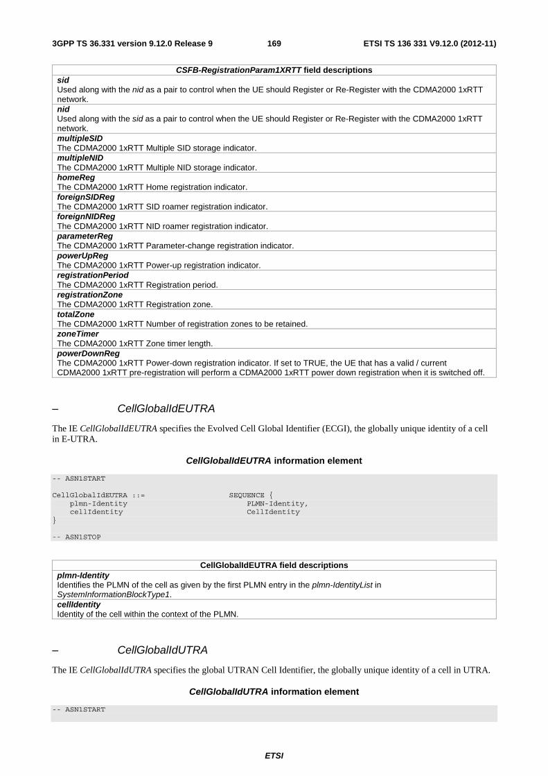
ETSI
ETSI TS 136 331 V9.12.0 (2012-11)1693GPP TS 36.331 version 9.12.0 Release 9
CSFB-RegistrationParam1XRTT field descriptions sid Used along with the nid as a pair to control when the UE should Register or Re-Register with the CDMA2000 1xRTT network. nid Used along with the sid as a pair to control when the UE should Register or Re-Register with the CDMA2000 1xRTT network. multipleSID The CDMA2000 1xRTT Multiple SID storage indicator. multipleNID The CDMA2000 1xRTT Multiple NID storage indicator. homeReg The CDMA2000 1xRTT Home registration indicator. foreignSIDReg The CDMA2000 1xRTT SID roamer registration indicator. foreignNIDReg The CDMA2000 1xRTT NID roamer registration indicator. parameterReg The CDMA2000 1xRTT Parameter-change registration indicator. powerUpReg The CDMA2000 1xRTT Power-up registration indicator. registrationPeriod The CDMA2000 1xRTT Registration period. registrationZone The CDMA2000 1xRTT Registration zone. totalZone The CDMA2000 1xRTT Number of registration zones to be retained. zoneTimer The CDMA2000 1xRTT Zone timer length. powerDownReg The CDMA2000 1xRTT Power-down registration indicator. If set to TRUE, the UE that has a valid / current CDMA2000 1xRTT pre-registration will perform a CDMA2000 1xRTT power down registration when it is switched off.
– CellGlobalIdEUTRA
The IE CellGlobalIdEUTRA specifies the Evolved Cell Global Identifier (ECGI), the globally unique identity of a cell in E-UTRA.
CellGlobalIdEUTRA information element
-- ASN1START CellGlobalIdEUTRA ::= SEQUENCE { plmn-Identity PLMN-Identity, cellIdentity CellIdentity } -- ASN1STOP
CellGlobalIdEUTRA field descriptions plmn-Identity Identifies the PLMN of the cell as given by the first PLMN entry in the plmn-IdentityList in SystemInformationBlockType1. cellIdentity Identity of the cell within the context of the PLMN.
– CellGlobalIdUTRA
The IE CellGlobalIdUTRA specifies the global UTRAN Cell Identifier, the globally unique identity of a cell in UTRA.
CellGlobalIdUTRA information element
-- ASN1START
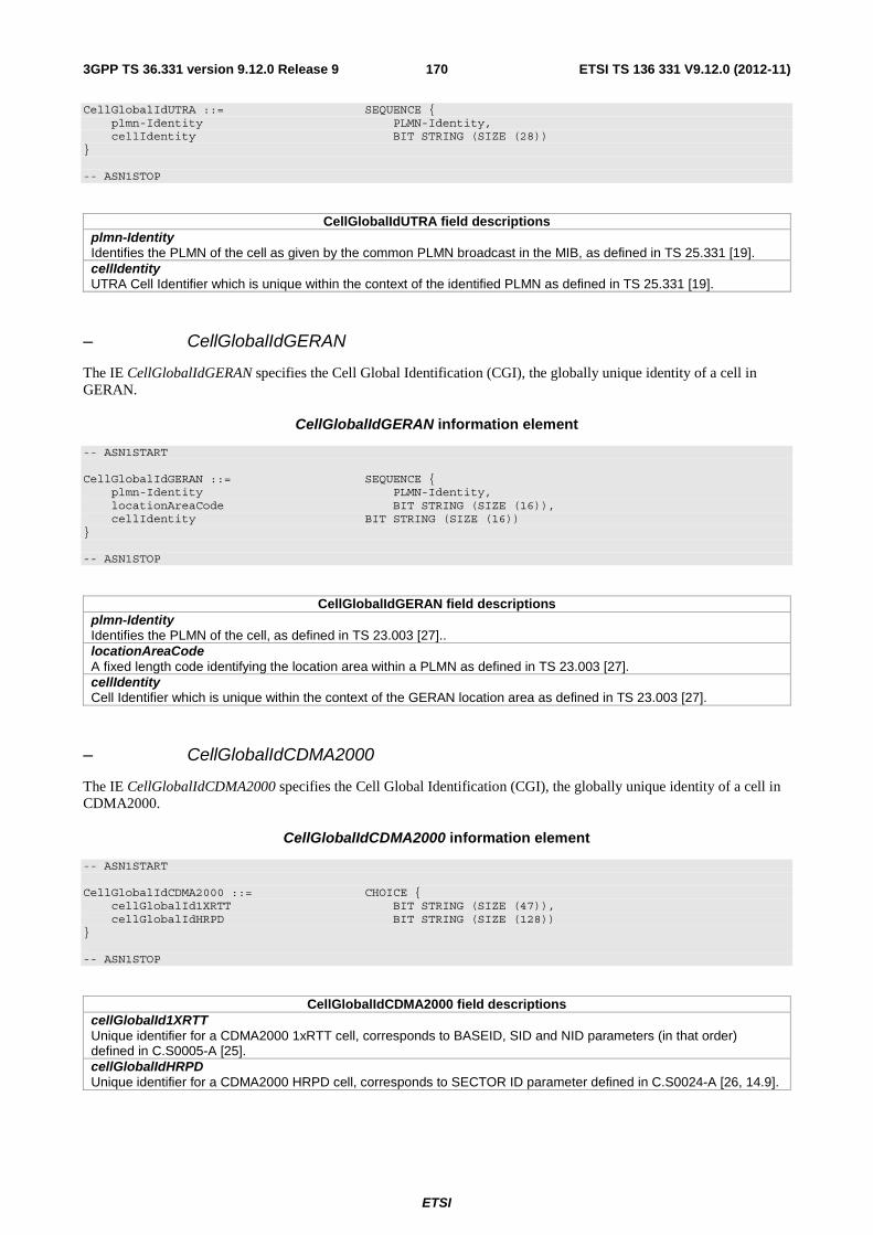
ETSI
ETSI TS 136 331 V9.12.0 (2012-11)1703GPP TS 36.331 version 9.12.0 Release 9
CellGlobalIdUTRA ::= SEQUENCE { plmn-Identity PLMN-Identity, cellIdentity BIT STRING (SIZE (28)) } -- ASN1STOP
CellGlobalIdUTRA field descriptions plmn-Identity Identifies the PLMN of the cell as given by the common PLMN broadcast in the MIB, as defined in TS 25.331 [19]. cellIdentity UTRA Cell Identifier which is unique within the context of the identified PLMN as defined in TS 25.331 [19].
– CellGlobalIdGERAN
The IE CellGlobalIdGERAN specifies the Cell Global Identification (CGI), the globally unique identity of a cell in GERAN.
CellGlobalIdGERAN information element
-- ASN1START CellGlobalIdGERAN ::= SEQUENCE { plmn-Identity PLMN-Identity, locationAreaCode BIT STRING (SIZE (16)), cellIdentity BIT STRING (SIZE (16)) } -- ASN1STOP
CellGlobalIdGERAN field descriptions plmn-Identity Identifies the PLMN of the cell, as defined in TS 23.003 [27].. locationAreaCode A fixed length code identifying the location area within a PLMN as defined in TS 23.003 [27]. cellIdentity Cell Identifier which is unique within the context of the GERAN location area as defined in TS 23.003 [27].
– CellGlobalIdCDMA2000
The IE CellGlobalIdCDMA2000 specifies the Cell Global Identification (CGI), the globally unique identity of a cell in CDMA2000.
CellGlobalIdCDMA2000 information element
-- ASN1START CellGlobalIdCDMA2000 ::= CHOICE { cellGlobalId1XRTT BIT STRING (SIZE (47)), cellGlobalIdHRPD BIT STRING (SIZE (128)) } -- ASN1STOP
CellGlobalIdCDMA2000 field descriptions cellGlobalId1XRTT Unique identifier for a CDMA2000 1xRTT cell, corresponds to BASEID, SID and NID parameters (in that order) defined in C.S0005-A [25]. cellGlobalIdHRPD Unique identifier for a CDMA2000 HRPD cell, corresponds to SECTOR ID parameter defined in C.S0024-A [26, 14.9].

ETSI
ETSI TS 136 331 V9.12.0 (2012-11)1713GPP TS 36.331 version 9.12.0 Release 9
– CSG-Identity
The IE CSG-Identity is used to identify a Closed Subscriber Group.
CSG-Identity information element
-- ASN1START CSG-Identity ::= BIT STRING (SIZE (27)) -- ASN1STOP
– FreqBandIndicator
The IE FreqBandIndicator indicates the E-UTRA operating band as defined in TS 36.101 [42, table 5.5-1].
FreqBandIndicator information element
-- ASN1START FreqBandIndicator ::= INTEGER (1..64) -- ASN1STOP
– MobilityControlInfo
The IE MobilityControlInfo includes parameters relevant for network controlled mobility to/within E-UTRA.
MobilityControlInfo information element
-- ASN1START MobilityControlInfo ::= SEQUENCE { targetPhysCellId PhysCellId, carrierFreq CarrierFreqEUTRA OPTIONAL, -- Cond HO-toEUTRA carrierBandwidth CarrierBandwidthEUTRA OPTIONAL, -- Cond HO-toEUTRA additionalSpectrumEmission AdditionalSpectrumEmission OPTIONAL, -- Cond HO-toEUTRA t304 ENUMERATED { ms50, ms100, ms150, ms200, ms500, ms1000, ms2000, spare1}, newUE-Identity C-RNTI, radioResourceConfigCommon RadioResourceConfigCommon, rach-ConfigDedicated RACH-ConfigDedicated OPTIONAL, -- Need OP ... } CarrierBandwidthEUTRA ::= SEQUENCE { dl-Bandwidth ENUMERATED { n6, n15, n25, n50, n75, n100, spare10, spare9, spare8, spare7, spare6, spare5, spare4, spare3, spare2, spare1}, ul-Bandwidth ENUMERATED { n6, n15, n25, n50, n75, n100, spare10, spare9, spare8, spare7, spare6, spare5, spare4, spare3, spare2, spare1} OPTIONAL -- Need OP } CarrierFreqEUTRA ::= SEQUENCE { dl-CarrierFreq ARFCN-ValueEUTRA, ul-CarrierFreq ARFCN-ValueEUTRA OPTIONAL -- Cond FDD } -- ASN1STOP
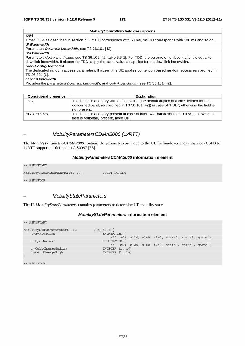
ETSI
ETSI TS 136 331 V9.12.0 (2012-11)1723GPP TS 36.331 version 9.12.0 Release 9
MobilityControlInfo field descriptions t304 Timer T304 as described in section 7.3. ms50 corresponds with 50 ms, ms100 corresponds with 100 ms and so on. dl-Bandwidth Parameter: Downlink bandwidth, see TS 36.101 [42]. ul-Bandwidth Parameter: Uplink bandwidth, see TS 36.101 [42, table 5.6-1]. For TDD, the parameter is absent and it is equal to downlink bandwidth. If absent for FDD, apply the same value as applies for the downlink bandwidth. rach-ConfigDedicated The dedicated random access parameters. If absent the UE applies contention based random access as specified in TS 36.321 [6]. carrierBandwidth Provides the parameters Downlink bandwidth, and Uplink bandwidth, see TS 36.101 [42].
Conditional presence Explanation FDD The field is mandatory with default value (the default duplex distance defined for the
concerned band, as specified in TS 36.101 [42]) in case of “FDD”; otherwise the field is not present.
HO-toEUTRA The field is mandatory present in case of inter-RAT handover to E-UTRA; otherwise the field is optionally present, need ON.
– MobilityParametersCDMA2000 (1xRTT)
The MobilityParametersCDMA2000 contains the parameters provided to the UE for handover and (enhanced) CSFB to 1xRTT support, as defined in C.S0097 [53].
MobilityParametersCDMA2000 information element
-- ASN1START MobilityParametersCDMA2000 ::= OCTET STRING -- ASN1STOP
– MobilityStateParameters
The IE MobilityStateParameters contains parameters to determine UE mobility state.
MobilityStateParameters information element
-- ASN1START MobilityStateParameters ::= SEQUENCE { t-Evaluation ENUMERATED { s30, s60, s120, s180, s240, spare3, spare2, spare1}, t-HystNormal ENUMERATED { s30, s60, s120, s180, s240, spare3, spare2, spare1}, n-CellChangeMedium INTEGER (1..16), n-CellChangeHigh INTEGER (1..16) } -- ASN1STOP

ETSI
ETSI TS 136 331 V9.12.0 (2012-11)1733GPP TS 36.331 version 9.12.0 Release 9
MobilityStateParameters field descriptions t-Evaluation The duration for evaluating criteria to enter mobility states. Corresponds to TCRmax in TS 36.304 [4]. Value in seconds, s30 corresponds to 30 s and so on. t-HystNormal The additional duration for evaluating criteria to enter normal mobility state. Corresponds to TCRmaxHyst in TS 36.304 [4]. Value in seconds, s30 corresponds to 30 s and so on. n-CellChangeMedium The number of cell changes to enter medium mobility state. Corresponds to NCR_M in TS 36.304 [4]. n-CellChangeHigh The number of cell changes to enter high mobility state. Corresponds to NCR_H in TS 36.304 [4].
– MultiBandInfoList
MultiBandInfoList information element
-- ASN1START MultiBandInfoList ::= SEQUENCE (SIZE (1..maxMultiBands)) OF FreqBandIndicator -- ASN1STOP
– PhysCellId
The IE PhysCellId is used to indicate the physical layer identity of the cell, as defined in TS 36.211 [21].
PhysCellId information element
-- ASN1START PhysCellId ::= INTEGER (0..503) -- ASN1STOP
– PhysCellIdRange
The IE PhysCellIdRange is used to encode either a single or a range of physical cell identities. The range is encoded by using a start value and by indicating the number of consecutive physical cell identities (including start) in the range.
PhysCellIdRange information element
-- ASN1START PhysCellIdRange ::= SEQUENCE { start PhysCellId, range ENUMERATED { n4, n8, n12, n16, n24, n32, n48, n64, n84, n96, n128, n168, n252, n504, spare2, spare1} OPTIONAL -- Need OP } -- ASN1STOP
PhysCellIdRange field descriptions start Indicates the lowest physical cell identity in the range. range Indicates the number of physical cell identities in the range (including start). Value n4 corresponds with 4, n8 corresponds with 8 and so on. The UE shall apply value 1 in case the field is absent, in which case only the physical cell identity value indicated by start applies.

ETSI
ETSI TS 136 331 V9.12.0 (2012-11)1743GPP TS 36.331 version 9.12.0 Release 9
– PhysCellIdRangeUTRA-FDDList
The IE PhysCellIdRangeUTRA-FDDList is used to encode one or more of PhysCellIdRangeUTRA-FDD. While the IE PhysCellIdRangeUTRA-FDD is used to encode either a single physical layer identity or a range of physical layer identities, i.e. primary scrambling codes. Each range is encoded by using a start value and by indicating the number of consecutive physical cell identities (including start) in the range.
PhysCellIdRangeUTRA-FDDList information element
-- ASN1START PhysCellIdRangeUTRA-FDDList-r9::= SEQUENCE (SIZE (1.. maxPhysCellIdRange-r9)) OF PhysCellIdRangeUTRA-FDD-r9 PhysCellIdRangeUTRA-FDD-r9 ::= SEQUENCE { start-r9 PhysCellIdUTRA-FDD, range-r9 INTEGER (2..512) OPTIONAL -- Need OP } -- ASN1STOP
PhysCellIdRangeUTRA-FDDList field descriptions start Indicates the lowest primary scrambling code in the range. range Indicates the number of primary scrambling codes in the range (including start). The UE shall apply value 1 in case the field is absent, in which case only the primary scrambling code value indicated by start applies.
– PhysCellIdCDMA2000
The IE PhysCellIdCDMA2000 identifies the PNOffset that represents the "Physical cell identity" in CDMA2000.
PhysCellIdCDMA2000 information element
-- ASN1START PhysCellIdCDMA2000 ::= INTEGER (0..maxPNOffset) -- ASN1STOP
– PhysCellIdGERAN
The IE PhysCellIdGERAN contains the Base Station Identity Code (BSIC).
PhysCellIdGERAN information element
-- ASN1START PhysCellIdGERAN ::= SEQUENCE { networkColourCode BIT STRING (SIZE (3)), baseStationColourCode BIT STRING (SIZE (3)) } -- ASN1STOP
PhysCellIdGERAN field descriptions networkColourCode Network Colour Code as defined in TS 23.003 [27]. baseStationColourCode Base station Colour Code as defined in TS 23.003 [27].

ETSI
ETSI TS 136 331 V9.12.0 (2012-11)1753GPP TS 36.331 version 9.12.0 Release 9
– PhysCellIdUTRA-FDD
The IE PhysCellIdUTRA-FDD is used to indicate the physical layer identity of the cell, i.e. the primary scrambling code, as defined in TS 25.331 [19].
PhysCellIdUTRA-FDD information element
-- ASN1START PhysCellIdUTRA-FDD ::= INTEGER (0..511) -- ASN1STOP
– PhysCellIdUTRA-TDD
The IE PhysCellIdUTRA-TDD is used to indicate the physical layer identity of the cell, i.e. the cell parameters ID (TDD), as specified in TS 25.331 [19]. Also corresponds to the Initial Cell Parameter Assignment in TS 25.223 [46].
PhysCellIdUTRA-TDD information element
-- ASN1START PhysCellIdUTRA-TDD ::= INTEGER (0..127) -- ASN1STOP
– PLMN-Identity
The IE PLMN-Identity identifies a Public Land Mobile Network. Further information regarding how to set the IE are specified in TS 23.003 [27].
PLMN-Identity information element
-- ASN1START PLMN-Identity ::= SEQUENCE { mcc MCC OPTIONAL, -- Cond MCC mnc MNC } MCC ::= SEQUENCE (SIZE (3)) OF MCC-MNC-Digit MNC ::= SEQUENCE (SIZE (2..3)) OF MCC-MNC-Digit MCC-MNC-Digit ::= INTEGER (0..9) -- ASN1STOP
PLMN-Identity field descriptions mcc The first element contains the first MCC digit, the second element the second MCC digit and so on. If the field is absent, it takes the same value as the mcc of the immediately preceding IE PLMN-Identity. See TS 23.003 [27]. mnc The first element contains the first MNC digit, the second element the second MNC digit and so on. See TS 23.003 [27].
Conditional presence Explanation MCC This IE is mandatory when PLMN-Identity is included in CellGlobalIdEUTRA, in
CellGlobalIdUTRA, in CellGlobalIdGERAN or in RegisteredMME. This IE is also mandatory in the first occurrence of the IE PLMN-Identity within the IE PLMN-IdentityList. Otherwise it is optional, need OP.

ETSI
ETSI TS 136 331 V9.12.0 (2012-11)1763GPP TS 36.331 version 9.12.0 Release 9
– PreRegistrationInfoHRPD
-- ASN1START PreRegistrationInfoHRPD ::= SEQUENCE { preRegistrationAllowed BOOLEAN, preRegistrationZoneId PreRegistrationZoneIdHRPD OPTIONAL, -- cond PreRegAllowed secondaryPreRegistrationZoneIdList SecondaryPreRegistrationZoneIdListHRPD OPTIONAL -- Need OR } SecondaryPreRegistrationZoneIdListHRPD ::= SEQUENCE (SIZE (1..2)) OF PreRegistrationZoneIdHRPD PreRegistrationZoneIdHRPD ::= INTEGER (0..255) -- ASN1STOP
PreRegistrationInfoHRPD field descriptions preRegistrationAllowed TRUE indicates that a UE shall perform a CDMA2000 HRPD pre-registration if the UE does not have a valid / current pre-registration. FALSE indicates that the UE is not allowed to perform CDMA2000 HRPD pre-registration in the current cell. preRegistrationZoneID ColorCode (see C.S0024-A [26], C.S0087-A [44]) of the CDMA2000 Reference Cell corresponding to the HRPD sector under the HRPD AN that is configured for this LTE cell. It is used to control when the UE should register or re-register. secondaryPreRegistrationZoneIdList List of SecondaryColorCodes (see C.S0024-A [26], C.S0087-A [44]) of the CDMA2000 Reference Cell corresponding to the HRPD sector under the HRPD AN that is configured for this LTE cell. They are used to control when the UE should re-register.
Conditional presence Explanation PreRegAllowed The field is mandatory in case the preRegistrationAllowed is set to ‘true’. Otherwise the
field is not present and the UE shall delete any existing value for this field.
– Q-QualMin
The IE Q-QualMin is used to indicate for cell selection/ re-selection the required minimum received RSRQ level in the (E-UTRA) cell. Corresponds to parameter Qqualmin in 36.304 [4]. Actual value Qqualmin = IE value [dB].
Q-QualMin information element
-- ASN1START Q-QualMin-r9 ::= INTEGER (-34..-3) -- ASN1STOP
– Q-RxLevMin
The IE Q-RxLevMin is used to indicate for cell selection/ re-selection the required minimum received RSRP level in the (E-UTRA) cell. Corresponds to parameter Qrxlevmin in 36.304 [4]. Actual value Qrxlevmin = IE value * 2 [dBm].
Q-RxLevMin information element
-- ASN1START Q-RxLevMin ::= INTEGER (-70..-22) -- ASN1STOP

ETSI
ETSI TS 136 331 V9.12.0 (2012-11)1773GPP TS 36.331 version 9.12.0 Release 9
– Q-OffsetRange
The IE Q-OffsetRange is used to indicate a cell or frequency specific offset to be applied when evaluating candidates for cell re-selection or when evaluating triggering conditions for measurement reporting. The value in dB. Value dB-24 corresponds to -24 dB, dB-22 corresponds to -22 dB and so on.
Q- OffsetRange information element
-- ASN1START Q-OffsetRange ::= ENUMERATED { dB-24, dB-22, dB-20, dB-18, dB-16, dB-14, dB-12, dB-10, dB-8, dB-6, dB-5, dB-4, dB-3, dB-2, dB-1, dB0, dB1, dB2, dB3, dB4, dB5, dB6, dB8, dB10, dB12, dB14, dB16, dB18, dB20, dB22, dB24} -- ASN1STOP
– Q-OffsetRangeInterRAT
The IE Q-OffsetRangeInterRAT is used to indicate a frequency specific offset to be applied when evaluating triggering conditions for measurement reporting. The value in dB.
Q-OffsetRangeInterRAT information element
-- ASN1START Q-OffsetRangeInterRAT ::= INTEGER (-15..15) -- ASN1STOP
– ReselectionThreshold
The IE ReselectionThreshold is used to indicate an Rx level threshold for cell reselection. Actual value of threshold = IE value * 2 [dB].
ReselectionThreshold information element
-- ASN1START ReselectionThreshold ::= INTEGER (0..31) -- ASN1STOP
– ReselectionThresholdQ
The IE ReselectionThresholdQ is used to indicate a quality level threshold for cell reselection. Actual value of threshold = IE value [dB].
ReselectionThresholdQ information element
-- ASN1START ReselectionThresholdQ-r9 ::= INTEGER (0..31) -- ASN1STOP
– SpeedStateScaleFactors
The IE SpeedStateScaleFactors concerns factors, to be applied when the UE is in medium or high speed state, used for scaling a mobility control related parameter.

ETSI
ETSI TS 136 331 V9.12.0 (2012-11)1783GPP TS 36.331 version 9.12.0 Release 9
SpeedStateScaleFactors information element
-- ASN1START SpeedStateScaleFactors ::= SEQUENCE { sf-Medium ENUMERATED {oDot25, oDot5, oDot75, lDot0}, sf-High ENUMERATED {oDot25, oDot5, oDot75, lDot0} } -- ASN1STOP
SpeedStateScaleFactors field descriptions sf-Medium The concerned mobility control related parameter is multiplied with this factor if the UE is in Medium Mobility state as defined in TS 36.304 [4]. Value oDot25 corresponds to 0.25, oDot5 corresponds to 0.5 , oDot75 corresponds to 0.75 and so on. sf-High The concerned mobility control related parameter is multiplied with this factor if the UE is in High Mobility state as defined in TS 36.304 [4]. Value oDot25 corresponds to 0.25, oDot5 corresponds to 0.5 , oDot75 corresponds to 0.75 and so on.
– SystemInfoListGERAN
The IE SystemInfoListGERAN contains system information.of a GERAN cell.
SystemInfoListGERAN information element
-- ASN1START SystemInfoListGERAN ::= SEQUENCE (SIZE (1..maxGERAN-SI)) OF OCTET STRING (SIZE (1..23)) -- ASN1STOP
SystemInfoListGERAN field descriptions SystemInfoListGERAN Each OCTET STRING contains one System Information (SI) message as defined in TS 44.018 [45, table 9.1.1] excluding the L2 Pseudo Length, the RR management Protocol Discriminator and the Skip Indicator or a complete Packet System Information (PSI) message as defined in TS 44.060 [36, table 11.2.1].
– SystemTimeInfoCDMA2000
The IE SystemTimeInfoCDMA2000 informs the UE about the absolute time in the current cell. The UE uses this absolute time knowledge to derive the CDMA2000 Physical cell identity, expressed as PNOffset, of neighbour CDMA2000 cells.
NOTE: The UE needs the CDMA2000 system time with a certain level of accuracy for performing measurements as well as for communicating with the CDMA2000 network (HRPD or 1xRTT).
SystemTimeInfoCDMA2000 information element
-- ASN1START SystemTimeInfoCDMA2000 ::= SEQUENCE { cdma-EUTRA-Synchronisation BOOLEAN, cdma-SystemTime CHOICE { synchronousSystemTime BIT STRING (SIZE (39)), asynchronousSystemTime BIT STRING (SIZE (49)) } } -- ASN1STOP

ETSI
ETSI TS 136 331 V9.12.0 (2012-11)1793GPP TS 36.331 version 9.12.0 Release 9
SystemTimeInfoCDMA2000 field descriptions cdma-EUTRA-Synchronisation TRUE indicates that the networks are synchronised i.e. there is no drift in the timing between E-UTRA and CDMA2000. FALSE indicates that the networks are not synchronised, i.e. the timing between E-UTRA and CDMA2000 can drift. synchronousSystemTime CDMA2000 system time corresponding to the SFN boundary at or after the ending boundary of the SI-window in which SystemInformationBlockType8 is transmitted. If synchronized to CDMA2000 system time then the size is 39 bits and the unit is 10 ms based on a 1.2288 Mcps chip rate. asynchronousSystemTime The CDMA2000 system time corresponding to the SFN boundary at or after the ending boundary of the SI-Window in which SystemInformationBlockType8 is transmitted. If not synchronized then the size is 49 bits and the unit is [8 CDMA2000 chips based on 1.2288 Mcps].
– TrackingAreaCode
The IE TrackingAreaCode is used to identify a tracking area within the scope of a PLMN, see TS 24.301 [35].
TrackingAreaCode information element
-- ASN1START TrackingAreaCode ::= BIT STRING (SIZE (16)) -- ASN1STOP
– T-Reselection
The IE T-Reselection concerns the cell reselection timer TreselectionRAT for E-UTRA, UTRA, GERAN or CDMA2000. Value in seconds.
T-Reselection information element
-- ASN1START T-Reselection ::= INTEGER (0..7) -- ASN1STOP
6.3.5 Measurement information elements
– AllowedMeasBandwidth
The IE AllowedMeasBandwidth is used to indicate the maximum allowed measurement bandwidth on a carrier frequency as defined by the parameter Transmission Bandwidth Configuration "NRB" TS 36.104 [47]. The values mbw6, mbw15, mbw25, mbw50, mbw75, mbw100 indicate 6, 15, 25, 50, 75 and 100 resource blocks respectively.
AllowedMeasBandwidth information element
-- ASN1START AllowedMeasBandwidth ::= ENUMERATED {mbw6, mbw15, mbw25, mbw50, mbw75, mbw100} -- ASN1STOP
– Hysteresis
The IE Hysteresis is a parameter used within the entry and leave condition of an event triggered reporting condition. The actual value is IE value * 0.5 dB.

ETSI
ETSI TS 136 331 V9.12.0 (2012-11)1803GPP TS 36.331 version 9.12.0 Release 9
Hysteresis information element
-- ASN1START Hysteresis ::= INTEGER (0..30) -- ASN1STOP
– MeasConfig
The IE MeasConfig specifies measurements to be performed by the UE, and covers intra-frequency, inter-frequency and inter-RAT mobility as well as configuration of measurement gaps.
MeasConfig information element
-- ASN1START MeasConfig ::= SEQUENCE { -- Measurement objects measObjectToRemoveList MeasObjectToRemoveList OPTIONAL, -- Need ON measObjectToAddModList MeasObjectToAddModList OPTIONAL, -- Need ON -- Reporting configurations reportConfigToRemoveList ReportConfigToRemoveList OPTIONAL, -- Need ON reportConfigToAddModList ReportConfigToAddModList OPTIONAL, -- Need ON -- Measurement identities measIdToRemoveList MeasIdToRemoveList OPTIONAL, -- Need ON measIdToAddModList MeasIdToAddModList OPTIONAL, -- Need ON -- Other parameters quantityConfig QuantityConfig OPTIONAL, -- Need ON measGapConfig MeasGapConfig OPTIONAL, -- Need ON s-Measure RSRP-Range OPTIONAL, -- Need ON preRegistrationInfoHRPD PreRegistrationInfoHRPD OPTIONAL, -- Need OP speedStatePars CHOICE { release NULL, setup SEQUENCE { mobilityStateParameters MobilityStateParameters, timeToTrigger-SF SpeedStateScaleFactors } } OPTIONAL, -- Need ON ... } MeasIdToRemoveList ::= SEQUENCE (SIZE (1..maxMeasId)) OF MeasId MeasObjectToRemoveList ::= SEQUENCE (SIZE (1..maxObjectId)) OF MeasObjectId ReportConfigToRemoveList ::= SEQUENCE (SIZE (1..maxReportConfigId)) OF ReportConfigId -- ASN1STOP
MeasConfig field descriptions measObjectToRemoveList List of measurement objects to remove. reportConfigToRemoveList List of measurement reporting configurations to remove. measIdToRemoveList List of measurement identities to remove. measGapConfig Used to setup and release measurement gaps. s-Measure Serving cell quality threshold controlling whether or not the UE is required to perform measurements of intra-frequency, inter-frequency and inter-RAT neighbouring cells. Value “0” indicates to disable s-Measure. PreRegistrationInfoHRPD The CDMA2000 HRPD Pre-Registration Information tells the UE if it should pre-register with the CDMA2000 HRPD network and identifies the Pre-registration zone to the UE. timeToTrigger-SF The timeToTrigger in ReportConfigEUTRA and in ReportConfigInterRAT are multiplied with the scaling factor applicable for the UE’s speed state.

ETSI
ETSI TS 136 331 V9.12.0 (2012-11)1813GPP TS 36.331 version 9.12.0 Release 9
– MeasGapConfig
The IE MeasGapConfig specifies the measurement gap configuration and controls setup/ release of measurement gaps.
MeasGapConfig information element
-- ASN1START MeasGapConfig ::= CHOICE { release NULL, setup SEQUENCE { gapOffset CHOICE { gp0 INTEGER (0..39), gp1 INTEGER (0..79), ... } } } -- ASN1STOP
MeasGapConfig field descriptions gapOffset Value gapOffset of gp0 corresponds to gap offset of Gap Pattern Id “0” with MGRP = 40ms, gapOffset of gp1 corresponds to gap offset of Gap Pattern Id “1” with MGRP = 80ms. Also used to specify the measurement gap pattern to be applied, as defined in TS 36.133 [16].
– MeasId
The IE MeasId is used to identify a measurement configuration, i.e., linking of a measurement object and a reporting configuration.
MeasId information element
-- ASN1START MeasId ::= INTEGER (1..maxMeasId) -- ASN1STOP
– MeasIdToAddModList
The IE MeasIdToAddModList concerns a list of measurement identities to add or modify, with for each entry the measId, the associated measObjectId and the associated reportConfigId.
MeasIdToAddModList information element
-- ASN1START MeasIdToAddModList ::= SEQUENCE (SIZE (1..maxMeasId)) OF MeasIdToAddMod MeasIdToAddMod ::= SEQUENCE { measId MeasId, measObjectId MeasObjectId, reportConfigId ReportConfigId } -- ASN1STOP
– MeasObjectCDMA2000
The IE MeasObjectCDMA2000 specifies information applicable for inter-RAT CDMA2000 neighbouring cells.

ETSI
ETSI TS 136 331 V9.12.0 (2012-11)1823GPP TS 36.331 version 9.12.0 Release 9
MeasObjectCDMA2000 information element
-- ASN1START MeasObjectCDMA2000 ::= SEQUENCE { cdma2000-Type CDMA2000-Type, carrierFreq CarrierFreqCDMA2000, searchWindowSize INTEGER (0..15) OPTIONAL, -- Need ON offsetFreq Q-OffsetRangeInterRAT DEFAULT 0, cellsToRemoveList CellIndexList OPTIONAL, -- Need ON cellsToAddModList CellsToAddModListCDMA2000 OPTIONAL, -- Need ON cellForWhichToReportCGI PhysCellIdCDMA2000 OPTIONAL, -- Need ON ... } CellsToAddModListCDMA2000 ::= SEQUENCE (SIZE (1..maxCellMeas)) OF CellsToAddModCDMA2000 CellsToAddModCDMA2000 ::= SEQUENCE { cellIndex INTEGER (1..maxCellMeas), physCellId PhysCellIdCDMA2000 } -- ASN1STOP
MeasObjectCDMA2000 field descriptions cdma2000-Type The type of CDMA2000 network: CDMA2000 1xRTT or CDMA2000 HRPD. carrierInfo Identifies CDMA2000 carrier frequency for which this configuration is valid. searchWindowSize Provides the search window size to be used by the UE for the neighbouring pilot, see C.S0005-A [25]. cellsToRemoveList List of cells to remove from the neighbouring cell list. cellsToAddModList List of cells to add/ modify in the neighbouring cell list. cellIndex Entry index in the neighbouring cell list. physCellId CDMA2000 Physical cell identity of a cell in neighbouring cell list expressed as PNOffset.
– MeasObjectEUTRA
The IE MeasObjectEUTRA specifies information applicable for intra-frequency or inter-frequency E-UTRA cells.
MeasObjectEUTRA information element
-- ASN1START MeasObjectEUTRA ::= SEQUENCE { carrierFreq ARFCN-ValueEUTRA, allowedMeasBandwidth AllowedMeasBandwidth, presenceAntennaPort1 PresenceAntennaPort1, neighCellConfig NeighCellConfig, offsetFreq Q-OffsetRange DEFAULT dB0, -- Cell list cellsToRemoveList CellIndexList OPTIONAL, -- Need ON cellsToAddModList CellsToAddModList OPTIONAL, -- Need ON -- Black list blackCellsToRemoveList CellIndexList OPTIONAL, -- Need ON blackCellsToAddModList BlackCellsToAddModList OPTIONAL, -- Need ON cellForWhichToReportCGI PhysCellId OPTIONAL, -- Need ON ... } CellsToAddModList ::= SEQUENCE (SIZE (1..maxCellMeas)) OF CellsToAddMod CellsToAddMod ::= SEQUENCE { cellIndex INTEGER (1..maxCellMeas), physCellId PhysCellId, cellIndividualOffset Q-OffsetRange }

ETSI
ETSI TS 136 331 V9.12.0 (2012-11)1833GPP TS 36.331 version 9.12.0 Release 9
BlackCellsToAddModList ::= SEQUENCE (SIZE (1..maxCellMeas)) OF BlackCellsToAddMod BlackCellsToAddMod ::= SEQUENCE { cellIndex INTEGER (1..maxCellMeas), physCellIdRange PhysCellIdRange } -- ASN1STOP
MeasObjectEUTRA field descriptions carrierFreq Identifies E-UTRA carrier frequency for which this configuration is valid. offsetFreq Offset value applicable to the carrier frequency. Value dB-24 corresponds to -24 dB, dB-22 corresponds to -22 dB and so on. cellsToRemoveList List of cells to remove from the cell list. cellsToAddModList List of cells to add/ modify in the cell list. cellIndex Entry index in the cell list. An entry may concern a range of cells, in which case this value applies to the entire range. physCellId Physical cell identity of a cell in the cell list. cellIndividualOffset Cell individual offset applicable to a specific cell. Value dB-24 corresponds to -24 dB, dB-22 corresponds to -22 dB and so on. blackCellsToRemoveList List of cells to remove from the black list of cells. blackCellsToAddMoList List of cells to add/ modify in the black list of cells. physCellIdRange Physical cell identity or a range of physical cell identities of cells in the black list.
– MeasObjectGERAN
The IE MeasObjectGERAN specifies information applicable for inter-RAT GERAN neighbouring frequencies.
MeasObjectGERAN information element
-- ASN1START MeasObjectGERAN ::= SEQUENCE { carrierFreqs CarrierFreqsGERAN, offsetFreq Q-OffsetRangeInterRAT DEFAULT 0, ncc-Permitted BIT STRING(SIZE (8)) DEFAULT '11111111'B, cellForWhichToReportCGI PhysCellIdGERAN OPTIONAL, -- Need ON ... } -- ASN1STOP
MeasObjectGERAN field descriptions ncc-Permitted Field encoded as a bit map, where bit N is set to "0" if a BCCH carrier with NCC = N-1 is not permitted for monitoring and set to "1" if a BCCH carrier with NCC = N-1 is permitted for monitoring; N = 1 to 8; bit 1 of the bitmap is the leading bit of the bit string.
– MeasObjectId
The IE MeasObjectId used to identify a measurement object configuration.

ETSI
ETSI TS 136 331 V9.12.0 (2012-11)1843GPP TS 36.331 version 9.12.0 Release 9
MeasObjectId information element
-- ASN1START MeasObjectId ::= INTEGER (1..maxObjectId) -- ASN1STOP
– MeasObjectToAddModList
The IE MeasObjectToAddModList concerns a list of measurement objects to add or modify
MeasObjectToAddModList information element
-- ASN1START MeasObjectToAddModList ::= SEQUENCE (SIZE (1..maxObjectId)) OF MeasObjectToAddMod MeasObjectToAddMod ::= SEQUENCE { measObjectId MeasObjectId, measObject CHOICE { measObjectEUTRA MeasObjectEUTRA, measObjectUTRA MeasObjectUTRA, measObjectGERAN MeasObjectGERAN, measObjectCDMA2000 MeasObjectCDMA2000, ... } } -- ASN1STOP
– MeasObjectUTRA
The IE MeasObjectUTRA specifies information applicable for inter-RAT UTRA neighbouring cells.
MeasObjectUTRA information element
-- ASN1START MeasObjectUTRA ::= SEQUENCE { carrierFreq ARFCN-ValueUTRA, offsetFreq Q-OffsetRangeInterRAT DEFAULT 0, cellsToRemoveList CellIndexList OPTIONAL, -- Need ON cellsToAddModList CHOICE { cellsToAddModListUTRA-FDD CellsToAddModListUTRA-FDD, cellsToAddModListUTRA-TDD CellsToAddModListUTRA-TDD } OPTIONAL, -- Need ON cellForWhichToReportCGI CHOICE { utra-FDD PhysCellIdUTRA-FDD, utra-TDD PhysCellIdUTRA-TDD } OPTIONAL, -- Need ON ..., [[ csg-allowedReportingCells-v930 CSG-AllowedReportingCells-r9 OPTIONAL -- Need ON ]] } CellsToAddModListUTRA-FDD ::= SEQUENCE (SIZE (1..maxCellMeas)) OF CellsToAddModUTRA-FDD CellsToAddModUTRA-FDD ::= SEQUENCE { cellIndex INTEGER (1..maxCellMeas), physCellId PhysCellIdUTRA-FDD } CellsToAddModListUTRA-TDD ::= SEQUENCE (SIZE (1..maxCellMeas)) OF CellsToAddModUTRA-TDD CellsToAddModUTRA-TDD ::= SEQUENCE { cellIndex INTEGER (1..maxCellMeas), physCellId PhysCellIdUTRA-TDD }

ETSI
ETSI TS 136 331 V9.12.0 (2012-11)1853GPP TS 36.331 version 9.12.0 Release 9
CSG-AllowedReportingCells-r9 ::= SEQUENCE { physCellIdRangeUTRA-FDDList-r9 PhysCellIdRangeUTRA-FDDList-r9 OPTIONAL -- Need OR } -- ASN1STOP
MeasObjectUTRA field descriptions carrierFreq Identifies UTRA carrier frequency for which this configuration is valid. cellsToRemoveList List of cells to remove from the neighbouring cell list. cellsToAddModListUTRA-FDD List of UTRA FDD cells to add/ modify in the neighbouring cell list. cellsToAddModListUTRA-TDD List of UTRA TDD cells to add/modify in the neighbouring cell list. cellIndex Entry index in the neighbouring cell list. csg-allowedReportingCells One or more ranges of physical cell identities for which UTRA-FDD reporting is allowed.
– MeasResults
The IE MeasResults covers measured results for intra-frequency, inter-frequency and inter- RAT mobility.
MeasResults information element
-- ASN1START MeasResults ::= SEQUENCE { measId MeasId, measResultServCell SEQUENCE { rsrpResult RSRP-Range, rsrqResult RSRQ-Range }, measResultNeighCells CHOICE { measResultListEUTRA MeasResultListEUTRA, measResultListUTRA MeasResultListUTRA, measResultListGERAN MeasResultListGERAN, measResultsCDMA2000 MeasResultsCDMA2000, ... } OPTIONAL, ..., [[ measResultForECID-r9 MeasResultForECID-r9 OPTIONAL ]] } MeasResultListEUTRA ::= SEQUENCE (SIZE (1..maxCellReport)) OF MeasResultEUTRA MeasResultEUTRA ::= SEQUENCE { physCellId PhysCellId, cgi-Info SEQUENCE { cellGlobalId CellGlobalIdEUTRA, trackingAreaCode TrackingAreaCode, plmn-IdentityList PLMN-IdentityList2 OPTIONAL } OPTIONAL, measResult SEQUENCE { rsrpResult RSRP-Range OPTIONAL, rsrqResult RSRQ-Range OPTIONAL, ..., [[ additionalSI-Info-r9 AdditionalSI-Info-r9 OPTIONAL ]] } } MeasResultListUTRA ::= SEQUENCE (SIZE (1..maxCellReport)) OF MeasResultUTRA MeasResultUTRA ::= SEQUENCE { physCellId CHOICE { fdd PhysCellIdUTRA-FDD, tdd PhysCellIdUTRA-TDD }, cgi-Info SEQUENCE {

ETSI
ETSI TS 136 331 V9.12.0 (2012-11)1863GPP TS 36.331 version 9.12.0 Release 9
cellGlobalId CellGlobalIdUTRA, locationAreaCode BIT STRING (SIZE (16)) OPTIONAL, routingAreaCode BIT STRING (SIZE (8)) OPTIONAL, plmn-IdentityList PLMN-IdentityList2 OPTIONAL } OPTIONAL, measResult SEQUENCE { utra-RSCP INTEGER (-5..91) OPTIONAL, utra-EcN0 INTEGER (0..49) OPTIONAL, ..., [[ additionalSI-Info-r9 AdditionalSI-Info-r9 OPTIONAL ]] } } MeasResultListGERAN ::= SEQUENCE (SIZE (1..maxCellReport)) OF MeasResultGERAN MeasResultGERAN ::= SEQUENCE { carrierFreq CarrierFreqGERAN, physCellId PhysCellIdGERAN, cgi-Info SEQUENCE { cellGlobalId CellGlobalIdGERAN, routingAreaCode BIT STRING (SIZE (8)) OPTIONAL } OPTIONAL, measResult SEQUENCE { rssi INTEGER (0..63), ... } } MeasResultsCDMA2000 ::= SEQUENCE { preRegistrationStatusHRPD BOOLEAN, measResultListCDMA2000 MeasResultListCDMA2000 } MeasResultListCDMA2000 ::= SEQUENCE (SIZE (1..maxCellReport)) OF MeasResultCDMA2000 MeasResultCDMA2000 ::= SEQUENCE { physCellId PhysCellIdCDMA2000, cgi-Info CellGlobalIdCDMA2000 OPTIONAL, measResult SEQUENCE { pilotPnPhase INTEGER (0..32767) OPTIONAL, pilotStrength INTEGER (0..63), ... } } MeasResultForECID-r9 ::= SEQUENCE { ue-RxTxTimeDiffResult-r9 INTEGER (0..4095), currentSFN-r9 BIT STRING (SIZE (10)) } PLMN-IdentityList2 ::= SEQUENCE (SIZE (1..5)) OF PLMN-Identity AdditionalSI-Info-r9 ::= SEQUENCE { csg-MemberStatus-r9 ENUMERATED {member} OPTIONAL, csg-Identity-r9 CSG-Identity OPTIONAL } -- ASN1STOP

ETSI
ETSI TS 136 331 V9.12.0 (2012-11)1873GPP TS 36.331 version 9.12.0 Release 9
MeasResults field descriptions measId Identifies the measurement identity for which the reporting is being performed. measResultServCell Measured result of the serving cell. measResultListEUTRA List of measured results for the maximum number of reported best cells for an E-UTRA measurement identity. rsrpResult Measured RSRP result of an E-UTRA cell. The rsrpResult is only reported if configured by the eNB. rsrqResult Measured RSRQ result of an E-UTRA cell. The rsrqResult is only reported if configured by the eNB. measResultListUTRA List of measured results for the maximum number of reported best cells for a UTRA measurement identity. measResultListGERAN List of measured results for the maximum number of reported best cells or frequencies for a GERAN measurement identity. measResultsCDMA2000 Contains the CDMA2000 HRPD pre-registration status and the list of CDMA2000 measurements. preRegistrationStatusHRPD Set to TRUE if the UE is currently pre-registered with CDMA2000 HRPD. Otherwise set to FALSE. This can be ignored by the eNB for CDMA2000 1xRTT. measResultListCDMA2000 List of measured results for the maximum number of reported best cells for a CDMA2000 measurement identity. measResult Measured result of an E-UTRA cell; Measured result of a UTRA cell; Measured result of a GERAN cell or frequency; or Measured result of a CDMA2000 cell. Measured result of UE Rx – Tx time difference. utra-RSCP According to CPICH_RSCP in TS 25.133 [29] for FDD and P-CCPCH_RSCP in TS 25.123 [30] for TDD. Thirty-one spare values. utra-EcN0 According to CPICH_Ec/No in TS 25.133 [29] for FDD. Fourteen spare values. The field is not present for TDD. rssi GERAN Carrier RSSI. RXLEV is mapped to a value between 0 and 63, TS 45.008 [28]. When mapping the RXLEV value to the RSSI bit string, the first/leftmost bit of the bit string contains the most significant bit. locationAreaCode A fixed length code identifying the location area within a PLMN, as defined in TS 23.003 [27]. routingAreaCode The RAC identity read from broadcast information, as defined in TS 23.003 [27]. plmn-IdentityList The list of PLMN Identity read from broadcast information when the multiple PLMN Identities are broadcast. This field contains the list of identities starting from the second entry of PLMN Identities in the broadcast information. pilotPnPhase Indicates the arrival time of a CDMA2000 pilot, measured relative to the UE’s time reference in units of PN chips, see C.S0005-A [25]. This information is used in either SRVCC handover or enhanced 1xRTT CS fallback procedure to CDMA2000 1xRTT. pilotStrength CDMA2000 Pilot Strength, the ratio of pilot power to total power in the signal bandwidth of a CDMA2000 Forward Channel. See C.S0005-A [25] for CDMA2000 1xRTT and C.S0024-A [26] for CDMA2000 HRPD. csg-MemberStatus Indicates whether or not the UE is a member of the CSG of the neighbour cell. ue-RxTxTimeDiffResult UE Rx-Tx time difference measurement result of the serving cell, provided by lower layers. According to UE Rx-Tx time difference report mapping in TS 36.133 [16]. currentSFN Indicates the current system frame number when receiving the UE Rx-Tx time difference measurement results from lower layer.
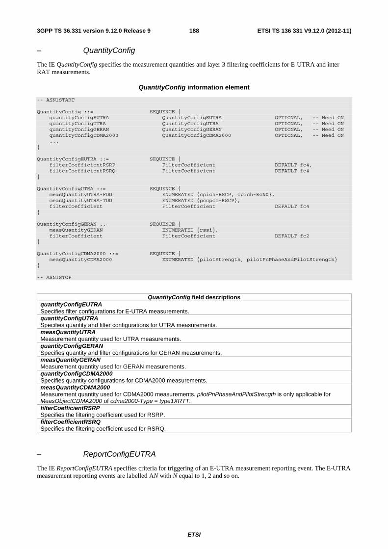
ETSI
ETSI TS 136 331 V9.12.0 (2012-11)1883GPP TS 36.331 version 9.12.0 Release 9
– QuantityConfig
The IE QuantityConfig specifies the measurement quantities and layer 3 filtering coefficients for E-UTRA and inter-RAT measurements.
QuantityConfig information element
-- ASN1START QuantityConfig ::= SEQUENCE { quantityConfigEUTRA QuantityConfigEUTRA OPTIONAL, -- Need ON quantityConfigUTRA QuantityConfigUTRA OPTIONAL, -- Need ON quantityConfigGERAN QuantityConfigGERAN OPTIONAL, -- Need ON quantityConfigCDMA2000 QuantityConfigCDMA2000 OPTIONAL, -- Need ON ... } QuantityConfigEUTRA ::= SEQUENCE { filterCoefficientRSRP FilterCoefficient DEFAULT fc4, filterCoefficientRSRQ FilterCoefficient DEFAULT fc4 } QuantityConfigUTRA ::= SEQUENCE { measQuantityUTRA-FDD ENUMERATED {cpich-RSCP, cpich-EcN0}, measQuantityUTRA-TDD ENUMERATED {pccpch-RSCP}, filterCoefficient FilterCoefficient DEFAULT fc4 } QuantityConfigGERAN ::= SEQUENCE { measQuantityGERAN ENUMERATED {rssi}, filterCoefficient FilterCoefficient DEFAULT fc2 } QuantityConfigCDMA2000 ::= SEQUENCE { measQuantityCDMA2000 ENUMERATED {pilotStrength, pilotPnPhaseAndPilotStrength} } -- ASN1STOP
QuantityConfig field descriptions quantityConfigEUTRA Specifies filter configurations for E-UTRA measurements. quantityConfigUTRA Specifies quantity and filter configurations for UTRA measurements. measQuantityUTRA Measurement quantity used for UTRA measurements. quantityConfigGERAN Specifies quantity and filter configurations for GERAN measurements. measQuantityGERAN Measurement quantity used for GERAN measurements. quantityConfigCDMA2000 Specifies quantity configurations for CDMA2000 measurements. measQuantityCDMA2000 Measurement quantity used for CDMA2000 measurements. pilotPnPhaseAndPilotStrength is only applicable for MeasObjectCDMA2000 of cdma2000-Type = type1XRTT. filterCoefficientRSRP Specifies the filtering coefficient used for RSRP. filterCoefficientRSRQ Specifies the filtering coefficient used for RSRQ.
– ReportConfigEUTRA
The IE ReportConfigEUTRA specifies criteria for triggering of an E-UTRA measurement reporting event. The E-UTRA measurement reporting events are labelled AN with N equal to 1, 2 and so on.
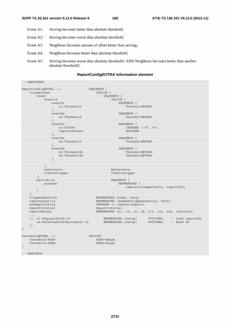
ETSI
ETSI TS 136 331 V9.12.0 (2012-11)1893GPP TS 36.331 version 9.12.0 Release 9
Event A1: Serving becomes better than absolute threshold;
Event A2: Serving becomes worse than absolute threshold;
Event A3: Neighbour becomes amount of offset better than serving;
Event A4: Neighbour becomes better than absolute threshold;
Event A5: Serving becomes worse than absolute threshold1 AND Neighbour becomes better than another absolute threshold2.
ReportConfigEUTRA information element
-- ASN1START ReportConfigEUTRA ::= SEQUENCE { triggerType CHOICE { event SEQUENCE { eventId CHOICE { eventA1 SEQUENCE { a1-Threshold ThresholdEUTRA }, eventA2 SEQUENCE { a2-Threshold ThresholdEUTRA }, eventA3 SEQUENCE { a3-Offset INTEGER (-30..30), reportOnLeave BOOLEAN }, eventA4 SEQUENCE { a4-Threshold ThresholdEUTRA }, eventA5 SEQUENCE { a5-Threshold1 ThresholdEUTRA, a5-Threshold2 ThresholdEUTRA }, ... }, hysteresis Hysteresis, timeToTrigger TimeToTrigger }, periodical SEQUENCE { purpose ENUMERATED { reportStrongestCells, reportCGI} } }, triggerQuantity ENUMERATED {rsrp, rsrq}, reportQuantity ENUMERATED {sameAsTriggerQuantity, both}, maxReportCells INTEGER (1..maxCellReport), reportInterval ReportInterval, reportAmount ENUMERATED {r1, r2, r4, r8, r16, r32, r64, infinity}, ..., [[ si-RequestForHO-r9 ENUMERATED {setup} OPTIONAL, -- Cond reportCGI ue-RxTxTimeDiffPeriodical-r9 ENUMERATED {setup} OPTIONAL -- Need OR ]] } ThresholdEUTRA ::= CHOICE{ threshold-RSRP RSRP-Range, threshold-RSRQ RSRQ-Range } -- ASN1STOP

ETSI
ETSI TS 136 331 V9.12.0 (2012-11)1903GPP TS 36.331 version 9.12.0 Release 9
ReportConfigEUTRA field descriptions eventId Choice of E-UTRA event triggered reporting criteria. aN-ThresholdM Threshold to be used in EUTRA measurement report triggering condition for event number aN. If multiple thresholds are defined for event number aN, the thresholds are differentiated by M. a3-Offset Offset value to be used in EUTRA measurement report triggering condition for event a3. The actual value is IE value * 0.5 dB. reportOnLeave Indicates whether or not the UE shall initiate the measurement reporting procedure when the leaving condition is met for a cell in cellsTriggeredList, as specified in 5.5.4.1. triggerQuantity The quantities used to evaluate the triggering condition for the event. The values rsrp and rsrq correspond to Reference Signal Received Power (RSRP) and Reference Signal Received Quality (RSRQ), see TS 36.214 [48]. timeToTrigger Time during which specific criteria for the event needs to be met in order to trigger a measurement report. reportQuantity The quantities to be included in the measurement report. The value both means that both the rsrp and rsrq quantities are to be included in the measurement report. maxReportCells Max number of cells, excluding the serving cell, to include in the measurement report. reportAmount Number of measurement reports applicable for triggerType ‘event’ as well as for triggerType ‘periodical’. In case purpose is set to ‘reportCGI’ only value 1 applies. ThresholdEUTRA For RSRP: RSRP based threshold for event evaluation. The actual value is IE value – 140 dBm. For RSRQ: RSRQ based threshold for event evaluation. The actual value is (IE value – 40)/2 dB. si-RequestForHO The field applies to the ‘reportCGI’ functionality, and when the field is included, the UE is allowed to use autonomous gaps in acquiring system information from the neighbour cell, applies a different value for T321, and includes different fields in the measurement report. ue-RxTxTimeDiffPeriodical If this field is present, the UE shall perform UE Rx-Tx time difference measurement reporting and ignore the fields triggerQuantity, reportQuantity and maxReportCells. If the field is present, the only applicable values for the corresponding triggerType and purpose are ‘periodical’ and ‘reportStrongestCells’ respectively.
Conditional presence Explanation reportCGI The field is optional, need OR, in case 'purpose' is included and set to 'reportCGI';
otherwise the field is not present.
– ReportConfigId
The IE ReportConfigId is used to identify a measurement reporting configuration.
ReportConfigId information element
-- ASN1START ReportConfigId ::= INTEGER (1..maxReportConfigId) -- ASN1STOP
– ReportConfigInterRAT
The IE ReportConfigInterRAT specifies criteria for triggering of an inter-RAT measurement reporting event. The inter-RAT measurement reporting events are labelled BN with N equal to 1, 2 and so on.

ETSI
ETSI TS 136 331 V9.12.0 (2012-11)1913GPP TS 36.331 version 9.12.0 Release 9
Event B1: Neighbour becomes better than absolute threshold;
Event B2: Serving becomes worse than absolute threshold1 AND Neighbour becomes better than another absolute threshold2.
The b1 and b2 event thresholds for CDMA2000 are the CDMA2000 pilot detection thresholds are expressed as an unsigned binary number equal to [-2 x 10 log 10 Ec/Io] in units of 0.5dB, see C.S0005-A [25] for details.
ReportConfigInterRAT information element
-- ASN1START ReportConfigInterRAT ::= SEQUENCE { triggerType CHOICE { event SEQUENCE { eventId CHOICE { eventB1 SEQUENCE { b1-Threshold CHOICE { b1-ThresholdUTRA ThresholdUTRA, b1-ThresholdGERAN ThresholdGERAN, b1-ThresholdCDMA2000 ThresholdCDMA2000 } }, eventB2 SEQUENCE { b2-Threshold1 ThresholdEUTRA, b2-Threshold2 CHOICE { b2-Threshold2UTRA ThresholdUTRA, b2-Threshold2GERAN ThresholdGERAN, b2-Threshold2CDMA2000 ThresholdCDMA2000 } }, ... }, hysteresis Hysteresis, timeToTrigger TimeToTrigger }, periodical SEQUENCE { purpose ENUMERATED { reportStrongestCells, reportStrongestCellsForSON, reportCGI} } }, maxReportCells INTEGER (1..maxCellReport), reportInterval ReportInterval, reportAmount ENUMERATED {r1, r2, r4, r8, r16, r32, r64, infinity}, ..., [[ si-RequestForHO-r9 ENUMERATED {setup} OPTIONAL -- Cond reportCGI ]] } ThresholdUTRA ::= CHOICE{ utra-RSCP INTEGER (-5..91), utra-EcN0 INTEGER (0..49) } ThresholdGERAN ::= INTEGER (0..63) ThresholdCDMA2000 ::= INTEGER (0..63) -- ASN1STOP
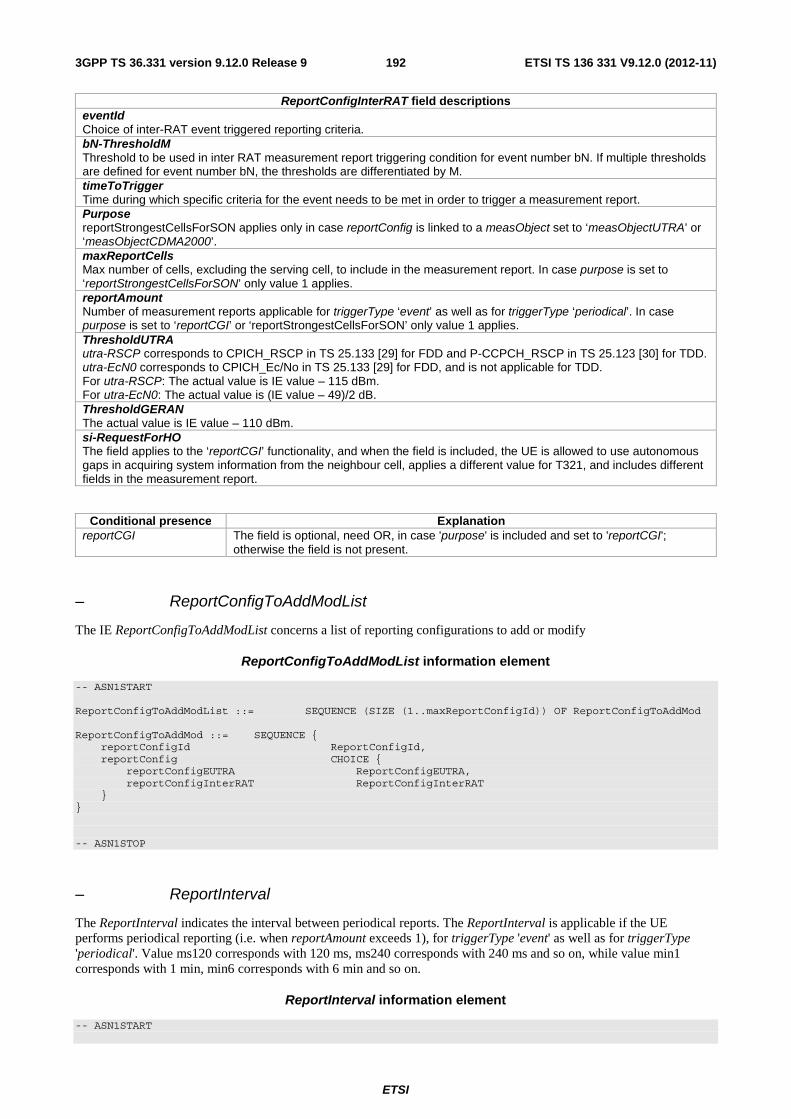
ETSI
ETSI TS 136 331 V9.12.0 (2012-11)1923GPP TS 36.331 version 9.12.0 Release 9
ReportConfigInterRAT field descriptions eventId Choice of inter-RAT event triggered reporting criteria. bN-ThresholdM Threshold to be used in inter RAT measurement report triggering condition for event number bN. If multiple thresholds are defined for event number bN, the thresholds are differentiated by M. timeToTrigger Time during which specific criteria for the event needs to be met in order to trigger a measurement report. Purpose reportStrongestCellsForSON applies only in case reportConfig is linked to a measObject set to ‘measObjectUTRA’ or ‘measObjectCDMA2000’. maxReportCells Max number of cells, excluding the serving cell, to include in the measurement report. In case purpose is set to ‘reportStrongestCellsForSON’ only value 1 applies. reportAmount Number of measurement reports applicable for triggerType ‘event’ as well as for triggerType ‘periodical’. In case purpose is set to ‘reportCGI’ or ‘reportStrongestCellsForSON’ only value 1 applies. ThresholdUTRA utra-RSCP corresponds to CPICH_RSCP in TS 25.133 [29] for FDD and P-CCPCH_RSCP in TS 25.123 [30] for TDD. utra-EcN0 corresponds to CPICH_Ec/No in TS 25.133 [29] for FDD, and is not applicable for TDD. For utra-RSCP: The actual value is IE value – 115 dBm. For utra-EcN0: The actual value is (IE value – 49)/2 dB. ThresholdGERAN The actual value is IE value – 110 dBm. si-RequestForHO The field applies to the ‘reportCGI’ functionality, and when the field is included, the UE is allowed to use autonomous gaps in acquiring system information from the neighbour cell, applies a different value for T321, and includes different fields in the measurement report.
Conditional presence Explanation reportCGI The field is optional, need OR, in case 'purpose' is included and set to 'reportCGI';
otherwise the field is not present.
– ReportConfigToAddModList
The IE ReportConfigToAddModList concerns a list of reporting configurations to add or modify
ReportConfigToAddModList information element
-- ASN1START ReportConfigToAddModList ::= SEQUENCE (SIZE (1..maxReportConfigId)) OF ReportConfigToAddMod ReportConfigToAddMod ::= SEQUENCE { reportConfigId ReportConfigId, reportConfig CHOICE { reportConfigEUTRA ReportConfigEUTRA, reportConfigInterRAT ReportConfigInterRAT } } -- ASN1STOP
– ReportInterval
The ReportInterval indicates the interval between periodical reports. The ReportInterval is applicable if the UE performs periodical reporting (i.e. when reportAmount exceeds 1), for triggerType 'event' as well as for triggerType 'periodical'. Value ms120 corresponds with 120 ms, ms240 corresponds with 240 ms and so on, while value min1 corresponds with 1 min, min6 corresponds with 6 min and so on.
ReportInterval information element
-- ASN1START

ETSI
ETSI TS 136 331 V9.12.0 (2012-11)1933GPP TS 36.331 version 9.12.0 Release 9
ReportInterval ::= ENUMERATED { ms120, ms240, ms480, ms640, ms1024, ms2048, ms5120, ms10240, min1, min6, min12, min30, min60, spare3, spare2, spare1} -- ASN1STOP
– RSRP-Range
The IE RSRP-Range specifies the value range used in RSRP measurements and thresholds. Integer value for RSRP measurements according to mapping table in TS 36.133 [16].
RSRP-Range information element
-- ASN1START RSRP-Range ::= INTEGER(0..97) -- ASN1STOP
– RSRQ-Range
The IE RSRQ-Range specifies the value range used in RSRQ measurements and thresholds. Integer value for RSRQ measurements according to mapping table in TS 36.133 [16].
RSRQ-Range information element
-- ASN1START RSRQ-Range ::= INTEGER(0..34) -- ASN1STOP
– TimeToTrigger
The IE TimeToTrigger specifies the value range used for time to trigger parameter, which concerns the time during which specific criteria for the event needs to be met in order to trigger a measurement report. Value ms0 corresponds to 0 ms, ms40 corresponds to 40 ms, and so on.
TimeToTrigger information element
-- ASN1START TimeToTrigger ::= ENUMERATED { ms0, ms40, ms64, ms80, ms100, ms128, ms160, ms256, ms320, ms480, ms512, ms640, ms1024, ms1280, ms2560, ms5120} -- ASN1STOP
6.3.6 Other information elements
– C-RNTI
The IE C-RNTI identifies a UE having a RRC connection within a cell.
C-RNTI information element
-- ASN1START C-RNTI ::= BIT STRING (SIZE (16)) -- ASN1STOP

ETSI
ETSI TS 136 331 V9.12.0 (2012-11)1943GPP TS 36.331 version 9.12.0 Release 9
– DedicatedInfoCDMA2000
The DedicatedInfoCDMA2000 is used to transfer UE specific CDMA2000 information between the network and the UE. The RRC layer is transparent for this information.
DedicatedInfoCDMA2000 information element
-- ASN1START DedicatedInfoCDMA2000 ::= OCTET STRING -- ASN1STOP
– DedicatedInfoNAS
The IE DedicatedInfoNAS is used to transfer UE specific NAS layer information between the network and the UE. The RRC layer is transparent for this information.
DedicatedInfoNAS information element
-- ASN1START DedicatedInfoNAS ::= OCTET STRING -- ASN1STOP
– FilterCoefficient
The IE FilterCoefficient specifies the measurement filtering coefficient. Value fc0 corresponds to k = 0, fc1 corresponds to k = 1, and so on.
FilterCoefficient information element
-- ASN1START FilterCoefficient ::= ENUMERATED { fc0, fc1, fc2, fc3, fc4, fc5, fc6, fc7, fc8, fc9, fc11, fc13, fc15, fc17, fc19, spare1, ...} -- ASN1STOP
– MMEC
The IE MMEC identifies an MME within the scope of an MME Group within a PLMN, see TS 23.003 [27].
MMEC information element
-- ASN1START MMEC ::= BIT STRING (SIZE (8)) -- ASN1STOP
– NeighCellConfig
The IE NeighCellConfig is used to provide the information related to MBSFN and TDD UL/DL configuration of neighbour cells.

ETSI
ETSI TS 136 331 V9.12.0 (2012-11)1953GPP TS 36.331 version 9.12.0 Release 9
NeighCellConfig information element
-- ASN1START NeighCellConfig ::= BIT STRING (SIZE (2)) -- ASN1STOP
NeighCellConfig field descriptions neighCellConfig Provides information related to MBSFN and TDD UL/DL configuration of neighbour cells of this frequency 00: Not all neighbour cells have the same MBSFN subframe allocation as serving cell 10: The MBSFN subframe allocations of all neighbour cells are identical to or subsets of that in the serving cell 01: No MBSFN subframes are present in all neighbour cells 11: Different UL/DL allocation in neighbouring cells for TDD compared to the serving cell For TDD, 00, 10 and 01 are only used for same UL/DL allocation in neighbouring cells compared to the serving cell.
– OtherConfig
The IE OtherConfig contains configuration related to other configuration
OtherConfig information element
-- ASN1START OtherConfig-r9 ::= SEQUENCE { reportProximityConfig-r9 ReportProximityConfig-r9 OPTIONAL, -- Need ON ... } ReportProximityConfig-r9 ::= SEQUENCE { proximityIndicationEUTRA-r9 ENUMERATED {enabled} OPTIONAL, -- Need OR proximityIndicationUTRA-r9 ENUMERATED {enabled} OPTIONAL -- Need OR } -- ASN1STOP
OtherConfig field descriptions reportProximityConfig Indicates, for each of the applicable RATs (EUTRA, UTRA), whether or not proximity indication is enabled for CSG member cells of the concerned RAT. Note.
NOTE: Enabling/ disabling of proximity indication includes enabling/ disabling of the related functionality e.g. autonomous search in connected mode.
– RAND-CDMA2000 (1xRTT)
The RAND-CDMA2000 concerns a random value, generated by the eNB, to be passed to the CDMA2000 upper layers.
RAND-CDMA2000 information element
-- ASN1START RAND-CDMA2000 ::= BIT STRING (SIZE (32)) -- ASN1STOP
– RAT-Type
The IE RAT-Type is used to indicate the radio access technology (RAT), including E-UTRA, of the requested/ transferred UE capabilities.

ETSI
ETSI TS 136 331 V9.12.0 (2012-11)1963GPP TS 36.331 version 9.12.0 Release 9
RAT-Type information element
-- ASN1START RAT-Type ::= ENUMERATED { eutra, utra, geran-cs, geran-ps, cdma2000-1XRTT, spare3, spare2, spare1, ...} -- ASN1STOP
– RRC-TransactionIdentifier
The IE RRC-TransactionIdentifier is used, together with the message type, for the identification of an RRC procedure (transaction).
RRC-TransactionIdentifier information element
-- ASN1START RRC-TransactionIdentifier ::= INTEGER (0..3) -- ASN1STOP
– S-TMSI
The IE S-TMSI contains an S-Temporary Mobile Subscriber Identity, a temporary UE identity provided by the EPC which uniquely identifies the UE within the tracking area, see TS 23.003 [27].
S-TMSI information element
-- ASN1START S-TMSI ::= SEQUENCE { mmec MMEC, m-TMSI BIT STRING (SIZE (32)) } -- ASN1STOP
S-TMSI field descriptions m-TMSI The first/leftmost bit of the bit string contains the most significant bit of the M-TMSI.
– UE-CapabilityRAT-ContainerList
The IE UE-CapabilityRAT-ContainerList contains list of containers, one for each RAT for which UE capabilities are transferred, if any.
UE-CapabilityRAT-ContainerList information element
-- ASN1START UE-CapabilityRAT-ContainerList ::=SEQUENCE (SIZE (0..maxRAT-Capabilities)) OF UE-CapabilityRAT-Container UE-CapabilityRAT-Container ::= SEQUENCE { rat-Type RAT-Type, ueCapabilityRAT-Container OCTET STRING } -- ASN1STOP

ETSI
ETSI TS 136 331 V9.12.0 (2012-11)1973GPP TS 36.331 version 9.12.0 Release 9
UECapabilityRAT-ContainerList field descriptions ueCapabilityRAT-Container Container for the UE capabilities of the indicated RAT. The encoding is defined in the specification of each RAT: For E-UTRA: the encoding of UE capabilities is defined in IE UE-EUTRA-Capability. For UTRA: the octet string contains the INTER RAT HANDOVER INFO message defined in TS 25.331 [19]. For GERAN CS: the octet string contains the concatenated string of the Mobile Station Classmark 2 and Mobile Station Classmark 3. The first 5 octets correspond to Mobile Station Classmark 2 and the following octets correspond to Mobile Station Classmark 3. The Mobile Station Classmark 2 is formatted as 'TLV' and is coded in the same way as the Mobile Station Classmark 2 information element in TS 24.008 [49]. The first octet is the Mobile station classmark 2 IEI and its value shall be set to 33H. The second octet is the Length of mobile station classmark 2 and its value shall be set to 3. The octet 3 contains the first octet of the value part of the Mobile Station Classmark 2 information element, the octet 4 contains the second octet of the value part of the Mobile Station Classmark 2 information element and so on. For each of these octets, the first/ leftmost/ most significant bit of the octet contains b8 of the corresponding octet of the Mobile Station Classmark 2. The Mobile Station Classmark 3 is formatted as 'V' and is coded in the same way as the value part in the Mobile station classmark 3 information element in TS 24.008 [49]. The sixth octet of this octet string contains octet 1 of the value part of Mobile station classmark 3, the seventh of octet of this octet string contains octet 2 of the value part of Mobile station classmark 3 and so on. Note. For GERAN PS: the encoding of UE capabilities is formatted as 'V' and is coded in the same way as the value part in the MS Radio Access Capability information element in TS 24.008 [49]. For CDMA2000-1XRTT: the octet string contains the A21 Mobile Subscription Information and the encoding of this is defined in A.S0008-C [33]. The A21 Mobile Subscription Information contains the supported CDMA2000 1xRTT band class and band sub-class information.
NOTE: The value part is specified by means of CSN.1, which encoding results in a bit string, to which final padding may be appended up to the next octet boundary TS 24.008 [49]. The first/ leftmost bit of the CSN.1 bit string is placed in the first/ leftmost/ most significant bit of the first octet. This continues until the last bit of the CSN.1 bit string, which is placed in the last/ rightmost/ least significant bit of the last octet.
– UE-EUTRA-Capability
The IE UE-EUTRA-Capability is used to convey the E-UTRA UE Radio Access Capability Parameters, see TS 36.306 [5], and the Feature Group Indicators for mandatory features (defined in Annex B.1) to the network. The IE UE-EUTRA-Capability is transferred in E-UTRA or in another RAT.
UE-EUTRA-Capability information element
-- ASN1START UE-EUTRA-Capability ::= SEQUENCE { accessStratumRelease AccessStratumRelease, ue-Category INTEGER (1..5), pdcp-Parameters PDCP-Parameters, phyLayerParameters PhyLayerParameters, rf-Parameters RF-Parameters, measParameters MeasParameters, featureGroupIndicators BIT STRING (SIZE (32)) OPTIONAL, interRAT-Parameters SEQUENCE { utraFDD IRAT-ParametersUTRA-FDD OPTIONAL, utraTDD128 IRAT-ParametersUTRA-TDD128 OPTIONAL, utraTDD384 IRAT-ParametersUTRA-TDD384 OPTIONAL, utraTDD768 IRAT-ParametersUTRA-TDD768 OPTIONAL, geran IRAT-ParametersGERAN OPTIONAL, cdma2000-HRPD IRAT-ParametersCDMA2000-HRPD OPTIONAL, cdma2000-1xRTT IRAT-ParametersCDMA2000-1XRTT OPTIONAL }, nonCriticalExtension UE-EUTRA-Capability-v920-IEs OPTIONAL } UE-EUTRA-Capability-v920-IEs ::= SEQUENCE { phyLayerParameters-v920 PhyLayerParameters-v920, interRAT-ParametersGERAN-v920 IRAT-ParametersGERAN-v920, interRAT-ParametersUTRA-v920 IRAT-ParametersUTRA-v920 OPTIONAL, interRAT-ParametersCDMA2000-v920 IRAT-ParametersCDMA2000-1XRTT-v920 OPTIONAL, deviceType-r9 ENUMERATED {noBenFromBatConsumpOpt} OPTIONAL, csg-ProximityIndicationParameters-r9 CSG-ProximityIndicationParameters-r9, neighCellSI-AcquisitionParameters-r9 NeighCellSI-AcquisitionParameters-r9, son-Parameters-r9 SON-Parameters-r9, nonCriticalExtension UE-EUTRA-Capability-v940-IEs OPTIONAL } UE-EUTRA-Capability-v940-IEs ::= SEQUENCE {
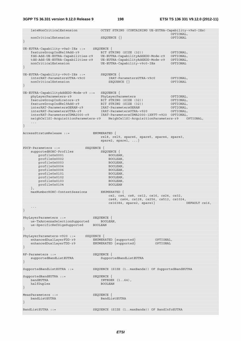
ETSI
ETSI TS 136 331 V9.12.0 (2012-11)1983GPP TS 36.331 version 9.12.0 Release 9
lateNonCriticalExtension OCTET STRING (CONTAINING UE-EUTRA-Capability-v9a0-IEs) OPTIONAL, nonCriticalExtension SEQUENCE {} OPTIONAL } UE-EUTRA-Capability-v9a0-IEs ::= SEQUENCE { featureGroupIndRel9Add-r9 BIT STRING (SIZE (32)) OPTIONAL, fdd-Add-UE-EUTRA-Capabilities-r9 UE-EUTRA-CapabilityAddXDD-Mode-r9 OPTIONAL, tdd-Add-UE-EUTRA-Capabilities-r9 UE-EUTRA-CapabilityAddXDD-Mode-r9 OPTIONAL, nonCriticalExtension UE-EUTRA-Capability-v9c0-IEs OPTIONAL } UE-EUTRA-Capability-v9c0-IEs ::= SEQUENCE { interRAT-ParametersUTRA-v9c0 IRAT-ParametersUTRA-v9c0 OPTIONAL, nonCriticalExtension SEQUENCE {} OPTIONAL } UE-EUTRA-CapabilityAddXDD-Mode-r9 ::= SEQUENCE { phyLayerParameters-r9 PhyLayerParameters OPTIONAL, featureGroupIndicators-r9 BIT STRING (SIZE (32)) OPTIONAL, featureGroupIndRel9Add-r9 BIT STRING (SIZE (32)) OPTIONAL, interRAT-ParametersGERAN-r9 IRAT-ParametersGERAN OPTIONAL, interRAT-ParametersUTRA-r9 IRAT-ParametersUTRA-v920 OPTIONAL, interRAT-ParametersCDMA2000-r9 IRAT-ParametersCDMA2000-1XRTT-v920 OPTIONAL, neighCellSI-AcquisitionParameters-r9 NeighCellSI-AcquisitionParameters-r9 OPTIONAL, ... } AccessStratumRelease ::= ENUMERATED { rel8, rel9, spare6, spare5, spare4, spare3, spare2, spare1, ...} PDCP-Parameters ::= SEQUENCE { supportedROHC-Profiles SEQUENCE { profile0x0001 BOOLEAN, profile0x0002 BOOLEAN, profile0x0003 BOOLEAN, profile0x0004 BOOLEAN, profile0x0006 BOOLEAN, profile0x0101 BOOLEAN, profile0x0102 BOOLEAN, profile0x0103 BOOLEAN, profile0x0104 BOOLEAN }, maxNumberROHC-ContextSessions ENUMERATED { cs2, cs4, cs8, cs12, cs16, cs24, cs32, cs48, cs64, cs128, cs256, cs512, cs1024, cs16384, spare2, spare1} DEFAULT cs16, ... } PhyLayerParameters ::= SEQUENCE { ue-TxAntennaSelectionSupported BOOLEAN, ue-SpecificRefSigsSupported BOOLEAN } PhyLayerParameters-v920 ::= SEQUENCE { enhancedDualLayerFDD-r9 ENUMERATED {supported} OPTIONAL, enhancedDualLayerTDD-r9 ENUMERATED {supported} OPTIONAL } RF-Parameters ::= SEQUENCE { supportedBandListEUTRA SupportedBandListEUTRA } SupportedBandListEUTRA ::= SEQUENCE (SIZE (1..maxBands)) OF SupportedBandEUTRA SupportedBandEUTRA ::= SEQUENCE { bandEUTRA INTEGER (1..64), halfDuplex BOOLEAN } MeasParameters ::= SEQUENCE { bandListEUTRA BandListEUTRA } BandListEUTRA ::= SEQUENCE (SIZE (1..maxBands)) OF BandInfoEUTRA

ETSI
ETSI TS 136 331 V9.12.0 (2012-11)1993GPP TS 36.331 version 9.12.0 Release 9
BandInfoEUTRA ::= SEQUENCE { interFreqBandList InterFreqBandList, interRAT-BandList InterRAT-BandList OPTIONAL } InterFreqBandList ::= SEQUENCE (SIZE (1..maxBands)) OF InterFreqBandInfo InterFreqBandInfo ::= SEQUENCE { interFreqNeedForGaps BOOLEAN } InterRAT-BandList ::= SEQUENCE (SIZE (1..maxBands)) OF InterRAT-BandInfo InterRAT-BandInfo ::= SEQUENCE { interRAT-NeedForGaps BOOLEAN } IRAT-ParametersUTRA-FDD ::= SEQUENCE { supportedBandListUTRA-FDD SupportedBandListUTRA-FDD } IRAT-ParametersUTRA-v920 ::= SEQUENCE { e-RedirectionUTRA-r9 ENUMERATED {supported} } IRAT-ParametersUTRA-v9c0 ::= SEQUENCE { voiceOverPS-HS-UTRA-FDD-r9 ENUMERATED {supported} OPTIONAL, voiceOverPS-HS-UTRA-TDD128-r9 ENUMERATED {supported} OPTIONAL, srvcc-FromUTRA-FDD-ToUTRA-FDD-r9 ENUMERATED {supported} OPTIONAL, srvcc-FromUTRA-FDD-ToGERAN-r9 ENUMERATED {supported} OPTIONAL, srvcc-FromUTRA-TDD128-ToUTRA-TDD128-r9 ENUMERATED {supported} OPTIONAL, srvcc-FromUTRA-TDD128-ToGERAN-r9 ENUMERATED {supported} OPTIONAL } SupportedBandListUTRA-FDD ::= SEQUENCE (SIZE (1..maxBands)) OF SupportedBandUTRA-FDD SupportedBandUTRA-FDD ::= ENUMERATED { bandI, bandII, bandIII, bandIV, bandV, bandVI, bandVII, bandVIII, bandIX, bandX, bandXI, bandXII, bandXIII, bandXIV, bandXV, bandXVI, ..., bandXVII-8a0, bandXVIII-8a0, bandXIX-8a0, bandXX-8a0, bandXXI-8a0, bandXXII-8a0, bandXXIII-8a0, bandXXIV-8a0, bandXXV-8a0, bandXXVI-8a0, bandXXVII-8a0, bandXXVIII-8a0, bandXXIX-8a0, bandXXX-8a0, bandXXXI-8a0, bandXXXII-8a0} IRAT-ParametersUTRA-TDD128 ::= SEQUENCE { supportedBandListUTRA-TDD128 SupportedBandListUTRA-TDD128 } SupportedBandListUTRA-TDD128 ::= SEQUENCE (SIZE (1..maxBands)) OF SupportedBandUTRA-TDD128 SupportedBandUTRA-TDD128 ::= ENUMERATED { a, b, c, d, e, f, g, h, i, j, k, l, m, n, o, p, ...} IRAT-ParametersUTRA-TDD384 ::= SEQUENCE { supportedBandListUTRA-TDD384 SupportedBandListUTRA-TDD384 } SupportedBandListUTRA-TDD384 ::= SEQUENCE (SIZE (1..maxBands)) OF SupportedBandUTRA-TDD384 SupportedBandUTRA-TDD384 ::= ENUMERATED { a, b, c, d, e, f, g, h, i, j, k, l, m, n, o, p, ...} IRAT-ParametersUTRA-TDD768 ::= SEQUENCE { supportedBandListUTRA-TDD768 SupportedBandListUTRA-TDD768 } SupportedBandListUTRA-TDD768 ::= SEQUENCE (SIZE (1..maxBands)) OF SupportedBandUTRA-TDD768 SupportedBandUTRA-TDD768 ::= ENUMERATED { a, b, c, d, e, f, g, h, i, j, k, l, m, n, o, p, ...} IRAT-ParametersGERAN ::= SEQUENCE { supportedBandListGERAN SupportedBandListGERAN, interRAT-PS-HO-ToGERAN BOOLEAN
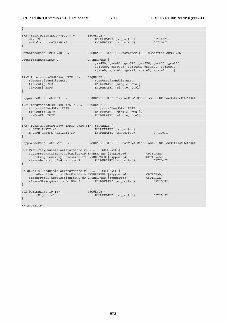
ETSI
ETSI TS 136 331 V9.12.0 (2012-11)2003GPP TS 36.331 version 9.12.0 Release 9
} IRAT-ParametersGERAN-v920 ::= SEQUENCE { dtm-r9 ENUMERATED {supported} OPTIONAL, e-RedirectionGERAN-r9 ENUMERATED {supported} OPTIONAL } SupportedBandListGERAN ::= SEQUENCE (SIZE (1..maxBands)) OF SupportedBandGERAN SupportedBandGERAN ::= ENUMERATED { gsm450, gsm480, gsm710, gsm750, gsm810, gsm850, gsm900P, gsm900E, gsm900R, gsm1800, gsm1900, spare5, spare4, spare3, spare2, spare1, ...} IRAT-ParametersCDMA2000-HRPD ::= SEQUENCE { supportedBandListHRPD SupportedBandListHRPD, tx-ConfigHRPD ENUMERATED {single, dual}, rx-ConfigHRPD ENUMERATED {single, dual} } SupportedBandListHRPD ::= SEQUENCE (SIZE (1..maxCDMA-BandClass)) OF BandclassCDMA2000 IRAT-ParametersCDMA2000-1XRTT ::= SEQUENCE { supportedBandList1XRTT SupportedBandList1XRTT, tx-Config1XRTT ENUMERATED {single, dual}, rx-Config1XRTT ENUMERATED {single, dual} } IRAT-ParametersCDMA2000-1XRTT-v920 ::= SEQUENCE { e-CSFB-1XRTT-r9 ENUMERATED {supported}, e-CSFB-ConcPS-Mob1XRTT-r9 ENUMERATED {supported} OPTIONAL } SupportedBandList1XRTT ::= SEQUENCE (SIZE (1..maxCDMA-BandClass)) OF BandclassCDMA2000 CSG-ProximityIndicationParameters-r9 ::= SEQUENCE { intraFreqProximityIndication-r9 ENUMERATED {supported} OPTIONAL, interFreqProximityIndication-r9 ENUMERATED {supported} OPTIONAL, utran-ProximityIndication-r9 ENUMERATED {supported} OPTIONAL } NeighCellSI-AcquisitionParameters-r9 ::= SEQUENCE { intraFreqSI-AcquisitionForHO-r9 ENUMERATED {supported} OPTIONAL, interFreqSI-AcquisitionForHO-r9 ENUMERATED {supported} OPTIONAL, utran-SI-AcquisitionForHO-r9 ENUMERATED {supported} OPTIONAL } SON-Parameters-r9 ::= SEQUENCE { rach-Report-r9 ENUMERATED {supported} OPTIONAL } -- ASN1STOP

ETSI
ETSI TS 136 331 V9.12.0 (2012-11)2013GPP TS 36.331 version 9.12.0 Release 9
UE-EUTRA-Capability field descriptions FDD/ TDD diff
accessStratumRelease Set to rel9 in this version of the specification.
-
e-RedirectionUTRA Yes intraFreqSI-AcquisitionForHO Yes interFreqSI-AcquisitionForHO Yes maxNumberROHC-ContextSessions Set to the maximum number of concurrently active ROHC contexts supported by the UE. cs2 corresponds with 2 (context sessions), cs4 corresponds with 4 and so on.
-
utran-SI-AcquisitionForHO Yes ue-Category UE category as defined in TS 36.306 [5]. Set to values 1 to 5 in this version of the specification.
-
bandEUTRA E-UTRA band as defined in TS 36.101 [42].
-
ue-TxAntennaSelectionSupported TRUE indicates that the UE is capable of supporting UE transmit antenna selection as described in TS 36.213 [23, 8.7].
Yes
ue-SpecificRefSigsSupported No halfDuplex If halfDuplex is set to true, only half duplex operation is supported for the band, otherwise full duplex operation is supported.
-
bandListEUTRA One entry corresponding to each supported E-UTRA band listed in the same order as in supportedBandListEUTRA.
-
interFreqBandList One entry corresponding to each supported E-UTRA band listed in the same order as in supportedBandListEUTRA.
-
interFreqNeedForGaps Indicates need for measurement gaps when operating on the E-UTRA band given by the entry in bandListEUTRA and measuring on the E-UTRA band given by the entry in interFreqBandList.
-
interRAT-BandList One entry corresponding to each supported band of another RAT listed in the same order as in the interRAT-Parameters.
-
interRAT-NeedForGaps Indicates need for DL measurement gaps when operating on the E-UTRA band given by the entry in bandListEUTRA and measuring on the inter-RAT band given by the entry in the interRAT-BandList.
-
SupportedBandUTRA-FDD UTRA band as defined in TS 25.101 [17].
-
SupportedBandUTRA-TDD128 UTRA band as defined in TS 25.102 [18].
-
SupportedBandUTRA-TDD384 UTRA band as defined in TS 25.102 [18].
-
SupportedBandUTRA-TDD768 UTRA band as defined in TS 25.102 [18].
-
SupportedBandGERAN GERAN band as defined in TS 45.005 [20].
No
dtm Indicates whether the UE supports DTM in GERAN.
-
SupportedBandListGERAN No SupportedBandListHRPD One entry corresponding to each supported CDMA2000 HRPD band class.
-
SupportedBandList1XRTT One entry corresponding to each supported CDMA2000 1xRTT band class.
-
voiceOverPS-HS-UTRA-FDD Indicates whether UE supports IMS voice according to GSMA IR.58 profile in UTRA FDD.
-
voiceOverPS-HS-UTRA-TDD128 Indicates whether UE supports IMS voice in UTRA TDD 1.28Mcps.
-
srvcc-FromUTRA-FDD-ToUTRA-FDD Indicates whether UE supports SRVCC handover from UTRA FDD PS HS to UTRA FDD CS.
-
srvcc-FromUTRA-FDD-ToGERAN Indicates whether UE supports SRVCC handover from UTRA FDD PS HS to GERAN CS.
-
srvcc-FromUTRA-TDD128-ToUTRA-TDD128 Indicates whether UE supports SRVCC handover from UTRA TDD 1.28Mcps PS HS to UTRA TDD 1.28Mcps CS.
-
srvcc-FromUTRA-TDD128-ToGERAN Indicates whether UE supports SRVCC handover from UTRA TDD 1.28Mcps PS HS to GERAN CS.
-

ETSI
ETSI TS 136 331 V9.12.0 (2012-11)2023GPP TS 36.331 version 9.12.0 Release 9
UE-EUTRA-Capability field descriptions FDD/ TDD diff
interRAT-PS-HO-ToGERAN Indicates whether the UE supports inter-RAT PS handover to GERAN or not.
Yes
featureGroupIndicators, featureGroupIndRel9Add The definitions of the bits in the bit string are described in Annex B.1.
Yes
e-CSFB-1XRTT Indicates whether the UE supports enhanced CS fallback to CDMA2000 1xRTT or not.
Yes
e-CSFB-ConcPS-Mob1XRTT Indicates whether the UE supports concurrent enhanced CS fallback to CDMA2000 1xRTT and PS handover/ redirection to CDMA2000 HRPD.
Yes
enhancedDualLayerTDD Indicates whether the UE supports enhanced dual layer (PDSCH transmission mode 8) for TDD or not. This bit shall be set to “TRUE” by a Rel-9 TDD UE when the functionality has been IOT tested.
-
deviceType UE may set the value to “noBenFromBatConsumpOpt” when it does not foresee to particularly benefit from NW-based battery consumption optimisation. Absence of this value means that the device does benefit from NW-based battery consumption optimisation.
-
NOTE 1: The IE UE-EUTRA-Capability does not include AS security capability information, since these are the same as the security capabilities that are signalled by NAS. Consequently AS need not provide "man-in-the-middle" protection for the security capabilities.
NOTE 2: The column FDD/ TDD diff indicates if the UE is allowed to signal, as part of the additional capabilities for an XDD mode i.e. within UE-EUTRA-CapabilityAddXDD-Mode-xNM, a different value compared to the value signalled elsewhere within UE-EUTRA-Capability (i.e. the common value, supported for both XDD modes). A '-' is used to indicate that it is not possible to signal different values (used for fields for which the field description is provided for other reasons).
– UE-TimersAndConstants
The IE UE-TimersAndConstants contains timers and constants used by the UE in either RRC_CONNECTED or RRC_IDLE.
UE-TimersAndConstants information element
-- ASN1START UE-TimersAndConstants ::= SEQUENCE { t300 ENUMERATED { ms100, ms200, ms300, ms400, ms600, ms1000, ms1500, ms2000}, t301 ENUMERATED { ms100, ms200, ms300, ms400, ms600, ms1000, ms1500, ms2000}, t310 ENUMERATED { ms0, ms50, ms100, ms200, ms500, ms1000, ms2000}, n310 ENUMERATED { n1, n2, n3, n4, n6, n8, n10, n20}, t311 ENUMERATED { ms1000, ms3000, ms5000, ms10000, ms15000, ms20000, ms30000}, n311 ENUMERATED { n1, n2, n3, n4, n5, n6, n8, n10}, ... } -- ASN1STOP
UE-TimersAndConstants field descriptions t3xy Timers are described in section 7.3. Value ms0 corresponds with 0 ms, ms50 corresponds with 50 ms and so on. n3xy Constants are described in section 7.4. n1 corresponds with 1, n2 corresponds with 2 and so on.

ETSI
ETSI TS 136 331 V9.12.0 (2012-11)2033GPP TS 36.331 version 9.12.0 Release 9
6.3.7 MBMS information elements
– MBMS-NotificationConfig
The IE MBMS-NotificationConfig specifies the MBMS notification related configuration parameters, that are applicable for all MBSFN areas.
MBMS-NotificationConfig information element
-- ASN1START MBMS-NotificationConfig-r9 ::= SEQUENCE { notificationRepetitionCoeff-r9 ENUMERATED {n2, n4}, notificationOffset-r9 INTEGER (0..10), notificationSF-Index-r9 INTEGER (1..6) } -- ASN1STOP
MBMS-NotificationConfig field descriptions notificationRepetitionCoeff Actual change notification repetition period common for all MCCHs that are configured= shortest modification period/ notificationRepetitionCoeff. The ‘shortest modificaton period’ corresponds with the lowest value of mcch-ModificationPeriod of all MCCHs that are configured. Value n2 corresponds to coefficient 2, and so on. notificationOffset Indicates, together with the notificationRepetitionCoeff, the radio frames in which the MCCH information change notification is scheduled i.e. the MCCH information change notification is scheduled in radio frames for which: SFN mod notification repetition period = notificationOffset notificationSF-Index Indicates the subframe used to transmit MCCH change notifications on PDCCH. FDD: Value 1, 2, 3, 4, 5 and 6 correspond with subframe #1, #2, #3 #6, #7, and #8 respectively. TDD: Value 1, 2, 3, 4, and 5 correspond with subframe #3, #4, #7, #8, and #9 respectively.
– MBSFN-AreaInfoList
The IE MBSFN-AreaInfoList contains the information required to acquire the MBMS control information associated with one or more MBSFN areas.
MBSFN-AreaInfoList information element
-- ASN1START MBSFN-AreaInfoList-r9 ::= SEQUENCE (SIZE(1..maxMBSFN-Area)) OF MBSFN-AreaInfo-r9 MBSFN-AreaInfo-r9 ::= SEQUENCE { mbsfn-AreaId-r9 INTEGER (0..255), non-MBSFNregionLength ENUMERATED {s1, s2}, notificationIndicator-r9 INTEGER (0..7), mcch-Config-r9 SEQUENCE { mcch-RepetitionPeriod-r9 ENUMERATED {rf32, rf64, rf128, rf256}, mcch-Offset-r9 INTEGER (0..10), mcch-ModificationPeriod-r9 ENUMERATED {rf512, rf1024}, sf-AllocInfo-r9 BIT STRING (SIZE(6)), signallingMCS-r9 ENUMERATED {n2, n7, n13, n19} }, ... } -- ASN1STOP

ETSI
ETSI TS 136 331 V9.12.0 (2012-11)2043GPP TS 36.331 version 9.12.0 Release 9
MBSFN-AreaInfoList field descriptions mbsfn-AreaId Indicates the MBSFN area ID, parameter NID
MBSFN in TS 36.211 [21, 6.10.2.1]. signallingMCS Indicates the Modulation and Coding Scheme (MCS) applicable for the subframes indicated by the field sf-AllocInfo and for each (P)MCH that is configured for this MBSFN area, for the first subframe allocated to the (P)MCH within each MCH scheduling period (which may contain the MCH scheduling information provided by MAC). Value n2
corresponds with the value 2 for parameter MCSI in TS 36.213 [23, Table 7.1.7.1-1], and so on. non-MBSFNregionLength Indicates how many symbols from the beginning of the subframe constitute the non-MBSFN region. This value applies in all subframes of the MBSFN area used for PMCH transmissions as indicated in the MSI. The values s1 and s2 correspond with 1 and 2 symbols, respectively: see TS 36.211 [21, Table 6.7-1]. notificationIndicator Indicates which PDCCH bit is used to notify the UE about change of the MCCH applicable for this MBSFN area. Value 0 corresponds with the least significant bit as defined in TS 36.212 [22, Section 5.3.3.1] and so on. mcch-RepetitionPeriod Defines the interval between transmissions of MCCH information, in radio frames, Value rf32 corresponds to 32 radio frames, rf64 corresponds to 64 radio frames and so on. mcch-Offset Indicates, together with the mcch-RepetitionPeriod, the radio frames in which MCCH is scheduled i.e. MCCH is scheduled in radio frames for which: SFN mod mcch-RepetitionPeriod = mcch-Offset mcch-ModificationPeriod Defines periodically appearing boundaries, i.e. radio frames for which SFN mod mcch-ModificationPeriod = 0, The contents of different transmissions of MCCH information can only be different if there is at least one such boundary in-between them. sf-AllocInfo Indicates the subframes of the radio frames indicated by the mcch-RepetitionPeriod and the mcch-Offset, that may carry MCCH. Value “1” indicates that the corresponding subframe is allocated. The following mapping applies: FDD: The first/ leftmost bit defines the allocation for subframe #1 of the radio frame indicated by mcch-RepetitionPeriod and mcch-Offset, the second bit for #2, the third bit for #3 , the fourth bit for #6, the fifth bit for #7 and the sixth bit for #8. TDD: The first/leftmost bit defines the allocation for subframe #3 of the radio frame indicated by mcch-RepetitionPeriod and mcch-Offset, the second bit for #4, third bit for #7, fourth bit for #8, fifth bit for #9. Uplink subframes are not allocated. The last bit is not used.
– MBSFN-SubframeConfig
The IE MBSFN-SubframeConfig defines subframes that are reserved for MBSFN in downlink.
MBSFN-SubframeConfig information element
-- ASN1START MBSFN-SubframeConfig ::= SEQUENCE { radioframeAllocationPeriod ENUMERATED {n1, n2, n4, n8, n16, n32}, radioframeAllocationOffset INTEGER (0..7), subframeAllocation CHOICE { oneFrame BIT STRING (SIZE(6)), fourFrames BIT STRING (SIZE(24)) } } -- ASN1STOP
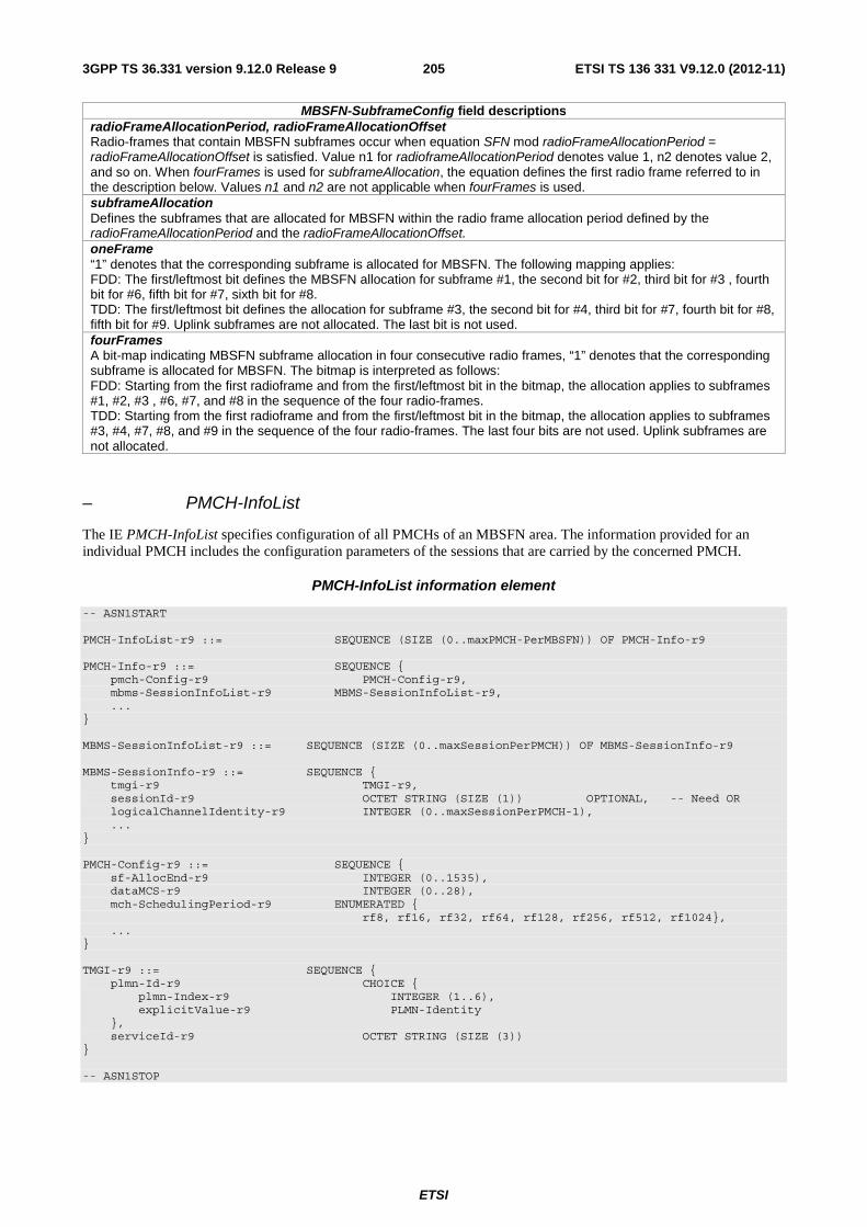
ETSI
ETSI TS 136 331 V9.12.0 (2012-11)2053GPP TS 36.331 version 9.12.0 Release 9
MBSFN-SubframeConfig field descriptions radioFrameAllocationPeriod, radioFrameAllocationOffset Radio-frames that contain MBSFN subframes occur when equation SFN mod radioFrameAllocationPeriod = radioFrameAllocationOffset is satisfied. Value n1 for radioframeAllocationPeriod denotes value 1, n2 denotes value 2, and so on. When fourFrames is used for subframeAllocation, the equation defines the first radio frame referred to in the description below. Values n1 and n2 are not applicable when fourFrames is used. subframeAllocation Defines the subframes that are allocated for MBSFN within the radio frame allocation period defined by the radioFrameAllocationPeriod and the radioFrameAllocationOffset. oneFrame “1” denotes that the corresponding subframe is allocated for MBSFN. The following mapping applies: FDD: The first/leftmost bit defines the MBSFN allocation for subframe #1, the second bit for #2, third bit for #3 , fourth bit for #6, fifth bit for #7, sixth bit for #8. TDD: The first/leftmost bit defines the allocation for subframe #3, the second bit for #4, third bit for #7, fourth bit for #8, fifth bit for #9. Uplink subframes are not allocated. The last bit is not used. fourFrames A bit-map indicating MBSFN subframe allocation in four consecutive radio frames, “1” denotes that the corresponding subframe is allocated for MBSFN. The bitmap is interpreted as follows: FDD: Starting from the first radioframe and from the first/leftmost bit in the bitmap, the allocation applies to subframes #1, #2, #3 , #6, #7, and #8 in the sequence of the four radio-frames. TDD: Starting from the first radioframe and from the first/leftmost bit in the bitmap, the allocation applies to subframes #3, #4, #7, #8, and #9 in the sequence of the four radio-frames. The last four bits are not used. Uplink subframes are not allocated.
– PMCH-InfoList
The IE PMCH-InfoList specifies configuration of all PMCHs of an MBSFN area. The information provided for an individual PMCH includes the configuration parameters of the sessions that are carried by the concerned PMCH.
PMCH-InfoList information element
-- ASN1START PMCH-InfoList-r9 ::= SEQUENCE (SIZE (0..maxPMCH-PerMBSFN)) OF PMCH-Info-r9 PMCH-Info-r9 ::= SEQUENCE { pmch-Config-r9 PMCH-Config-r9, mbms-SessionInfoList-r9 MBMS-SessionInfoList-r9, ... } MBMS-SessionInfoList-r9 ::= SEQUENCE (SIZE (0..maxSessionPerPMCH)) OF MBMS-SessionInfo-r9 MBMS-SessionInfo-r9 ::= SEQUENCE { tmgi-r9 TMGI-r9, sessionId-r9 OCTET STRING (SIZE (1)) OPTIONAL, -- Need OR logicalChannelIdentity-r9 INTEGER (0..maxSessionPerPMCH-1), ... } PMCH-Config-r9 ::= SEQUENCE { sf-AllocEnd-r9 INTEGER (0..1535), dataMCS-r9 INTEGER (0..28), mch-SchedulingPeriod-r9 ENUMERATED { rf8, rf16, rf32, rf64, rf128, rf256, rf512, rf1024}, ... } TMGI-r9 ::= SEQUENCE { plmn-Id-r9 CHOICE { plmn-Index-r9 INTEGER (1..6), explicitValue-r9 PLMN-Identity }, serviceId-r9 OCTET STRING (SIZE (3)) } -- ASN1STOP
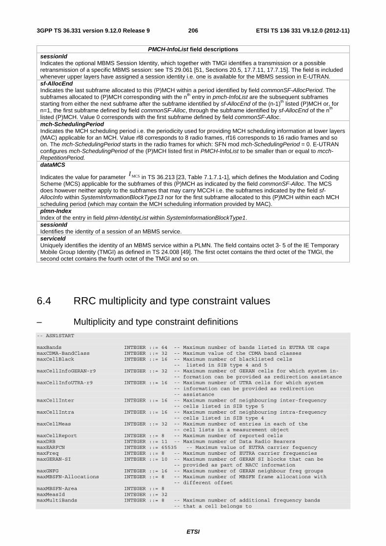
ETSI
ETSI TS 136 331 V9.12.0 (2012-11)2063GPP TS 36.331 version 9.12.0 Release 9
PMCH-InfoList field descriptions sessionId Indicates the optional MBMS Session Identity, which together with TMGI identifies a transmission or a possible retransmission of a specific MBMS session: see TS 29.061 [51, Sections 20.5, 17.7.11, 17.7.15]. The field is included whenever upper layers have assigned a session identity i.e. one is available for the MBMS session in E-UTRAN. sf-AllocEnd Indicates the last subframe allocated to this (P)MCH within a period identified by field commonSF-AllocPeriod. The subframes allocated to (P)MCH corresponding with the nth entry in pmch-InfoList are the subsequent subframes starting from either the next subframe after the subframe identified by sf-AllocEnd of the (n-1)th listed (P)MCH or, for n=1, the first subframe defined by field commonSF-Alloc, through the subframe identified by sf-AllocEnd of the nth listed (P)MCH. Value 0 corresponds with the first subframe defined by field commonSF-Alloc. mch-SchedulingPeriod Indicates the MCH scheduling period i.e. the periodicity used for providing MCH scheduling information at lower layers (MAC) applicable for an MCH. Value rf8 corresponds to 8 radio frames, rf16 corresponds to 16 radio frames and so on. The mch-SchedulingPeriod starts in the radio frames for which: SFN mod mch-SchedulingPeriod = 0. E-UTRAN configures mch-SchedulingPeriod of the (P)MCH listed first in PMCH-InfoList to be smaller than or equal to mcch-RepetitionPeriod. dataMCS
Indicates the value for parameter MCSI in TS 36.213 [23, Table 7.1.7.1-1], which defines the Modulation and Coding Scheme (MCS) applicable for the subframes of this (P)MCH as indicated by the field commonSF-Alloc. The MCS does however neither apply to the subframes that may carry MCCH i.e. the subframes indicated by the field sf-AllocInfo within SystemInformationBlockType13 nor for the first subframe allocated to this (P)MCH within each MCH scheduling period (which may contain the MCH scheduling information provided by MAC). plmn-Index Index of the entry in field plmn-IdentityList within SystemInformationBlockType1. sessionId Identifies the identity of a session of an MBMS service. serviceId Uniquely identifies the identity of an MBMS service within a PLMN. The field contains octet 3- 5 of the IE Temporary Mobile Group Identity (TMGI) as defined in TS 24.008 [49]. The first octet contains the third octet of the TMGI, the second octet contains the fourth octet of the TMGI and so on.
6.4 RRC multiplicity and type constraint values
– Multiplicity and type constraint definitions -- ASN1START maxBands INTEGER ::= 64 -- Maximum number of bands listed in EUTRA UE caps maxCDMA-BandClass INTEGER ::= 32 -- Maximum value of the CDMA band classes maxCellBlack INTEGER ::= 16 -- Maximum number of blacklisted cells -- listed in SIB type 4 and 5 maxCellInfoGERAN-r9 INTEGER ::= 32 -- Maximum number of GERAN cells for which system in- -- formation can be provided as redirection assistance maxCellInfoUTRA-r9 INTEGER ::= 16 -- Maximum number of UTRA cells for which system -- information can be provided as redirection -- assistance maxCellInter INTEGER ::= 16 -- Maximum number of neighbouring inter-frequency -- cells listed in SIB type 5 maxCellIntra INTEGER ::= 16 -- Maximum number of neighbouring intra-frequency -- cells listed in SIB type 4 maxCellMeas INTEGER ::= 32 -- Maximum number of entries in each of the -- cell lists in a measurement object maxCellReport INTEGER ::= 8 -- Maximum number of reported cells maxDRB INTEGER ::= 11 -- Maximum number of Data Radio Bearers maxEARFCN INTEGER ::= 65535 -- Maximum value of EUTRA carrier fequency maxFreq INTEGER ::= 8 -- Maximum number of EUTRA carrier frequencies maxGERAN-SI INTEGER ::= 10 -- Maximum number of GERAN SI blocks that can be -- provided as part of NACC information maxGNFG INTEGER ::= 16 -- Maximum number of GERAN neighbour freq groups maxMBSFN-Allocations INTEGER ::= 8 -- Maximum number of MBSFN frame allocations with -- different offset maxMBSFN-Area INTEGER ::= 8 maxMeasId INTEGER ::= 32 maxMultiBands INTEGER ::= 8 -- Maximum number of additional frequency bands -- that a cell belongs to

ETSI
ETSI TS 136 331 V9.12.0 (2012-11)2073GPP TS 36.331 version 9.12.0 Release 9
maxObjectId INTEGER ::= 32 maxPageRec INTEGER ::= 16 -- maxPhysCellIdRange-r9 INTEGER ::= 4 -- Maximum number of physical cell identity ranges maxPNOffset INTEGER ::= 511 -- Maximum number of CDMA2000 PNOffsets maxPMCH-PerMBSFN INTEGER ::= 15 maxRAT-Capabilities INTEGER ::= 8 -- Maximum number of interworking RATs (incl EUTRA) maxReportConfigId INTEGER ::= 32 maxSessionPerPMCH INTEGER ::= 29 maxSessionPerPMCH-1 INTEGER ::= 28 maxSIB INTEGER ::= 32 -- Maximum number of SIBs maxSIB-1 INTEGER ::= 31 maxSI-Message INTEGER ::= 32 -- Maximum number of SI messages maxUTRA-FDD-Carrier INTEGER ::= 16 -- Maximum number of UTRA FDD carrier frequencies maxUTRA-TDD-Carrier INTEGER ::= 16 -- Maximum number of UTRA TDD carrier frequencies -- ASN1STOP
NOTE: The value of maxDRB align with SA2.
– End of EUTRA-RRC-Definitions -- ASN1START END -- ASN1STOP
7 Variables and constants
7.1 UE variables NOTE: To facilitate the specification of the UE behavioural requirements, UE variables are represented using
ASN.1. Unless explicitly specified otherwise, it is however up to UE implementation how to store the variables. The optionality of the IEs in ASN.1 is used only to indicate that the values may not always be available.
– EUTRA-UE-Variables
This ASN.1 segment is the start of the E-UTRA UE variable definitions.
-- ASN1START EUTRA-UE-Variables DEFINITIONS AUTOMATIC TAGS ::= BEGIN IMPORTS CarrierFreqGERAN, CellIdentity, SpeedStateScaleFactors, C-RNTI, MeasId, MeasIdToAddModList, MeasObjectToAddModList, MobilityStateParameters, NeighCellConfig, PhysCellId, PhysCellIdCDMA2000, PhysCellIdGERAN, PhysCellIdUTRA-FDD, PhysCellIdUTRA-TDD, QuantityConfig, ReportConfigToAddModList, RSRP-Range, maxCellMeas, maxMeasId FROM EUTRA-RRC-Definitions; -- ASN1STOP

ETSI
ETSI TS 136 331 V9.12.0 (2012-11)2083GPP TS 36.331 version 9.12.0 Release 9
– VarMeasConfig
The UE variable VarMeasConfig includes the accumulated configuration of the measurements to be performed by the UE, covering intra-frequency, inter-frequency and inter-RAT mobility related measurements.
VarMeasConfig UE variable
-- ASN1START VarMeasConfig ::= SEQUENCE { -- Measurement identities measIdList MeasIdToAddModList OPTIONAL, -- Measurement objects measObjectList MeasObjectToAddModList OPTIONAL, -- Reporting configurations reportConfigList ReportConfigToAddModList OPTIONAL, -- Other parameters quantityConfig QuantityConfig OPTIONAL, s-Measure RSRP-Range OPTIONAL, speedStatePars CHOICE { release NULL, setup SEQUENCE { mobilityStateParameters MobilityStateParameters, timeToTrigger-SF SpeedStateScaleFactors } } OPTIONAL } -- ASN1STOP
– VarMeasReportList
The UE variable VarMeasReportList includes information about the measurements for which the triggering conditions have been met.
VarMeasReportList UE variable
-- ASN1START VarMeasReportList ::= SEQUENCE (SIZE (1..maxMeasId)) OF VarMeasReport VarMeasReport ::= SEQUENCE { -- List of measurement that have been triggered measId MeasId, cellsTriggeredList CellsTriggeredList OPTIONAL, numberOfReportsSent INTEGER } CellsTriggeredList ::= SEQUENCE (SIZE (1..maxCellMeas)) OF CHOICE { physCellIdEUTRA PhysCellId, physCellIdUTRA CHOICE { fdd PhysCellIdUTRA-FDD, tdd PhysCellIdUTRA-TDD }, physCellIdGERAN SEQUENCE { carrierFreq CarrierFreqGERAN, physCellId PhysCellIdGERAN }, physCellIdCDMA2000 PhysCellIdCDMA2000 } -- ASN1STOP
– VarShortMAC-Input
The UE variable VarShortMAC-Input specifies the input used to generate the shortMAC-I.

ETSI
ETSI TS 136 331 V9.12.0 (2012-11)2093GPP TS 36.331 version 9.12.0 Release 9
VarShortMAC-Input UE variable
-- ASN1START VarShortMAC-Input ::= SEQUENCE { cellIdentity CellIdentity, physCellId PhysCellId, c-RNTI C-RNTI } -- ASN1STOP
VarShortMAC-Input field descriptions cellIdentity Set to CellIdentity of the current cell. physCellId Set to the physical cell identity of the cell the UE was connected to prior to the failure. c-RNTI Set to C-RNTI that the UE had in the cell it was connected to prior to the failure.
– Multiplicity and type constraint definitions
This section includes multiplicity and type constraints applicable (only) for UE variables.
-- ASN1START -- ASN1STOP
– End of EUTRA-UE-Variables
-- ASN1START END -- ASN1STOP
7.2 Counters Counter Reset Incremented When reaching max value

ETSI
ETSI TS 136 331 V9.12.0 (2012-11)2103GPP TS 36.331 version 9.12.0 Release 9
7.3 Timers (Informative) Timer Start Stop At expiry
T300
Transmission of RRCConnectionRequest
Reception of RRCConnectionSetup or RRCConnectionReject message, cell re-selection and upon abortion of connection establishment by upper layers
Perform the actions as specified in 5.3.3.6
T301 Transmission of RRCConnectionReestabilshmentRequest
Reception of RRCConnectionReestablishment or RRCConnectionReestablishmentReject message as well as when the selected cell becomes unsuitable
Go to RRC_IDLE
T302 Reception of RRCConnectionReject while performing RRC connection establishment
Upon entering RRC_CONNECTED and upon cell re-selection
Inform upper layers about barring alleviation as specified in 5.3.3.7
T303 Access barred while performing RRC connection establishment for mobile originating calls
Upon entering RRC_CONNECTED and upon cell re-selection
Inform upper layers about barring alleviation as specified in 5.3.3.7
T304 Reception of RRCConnectionReconfiguration message including the MobilityControl Info or reception of MobilityFromEUTRACommand message including CellChangeOrder
Criterion for successful completion of handover to EUTRA or cell change order is met (the criterion is specified in the target RAT in case of inter-RAT)
In case of cell change order from E-UTRA or intra E-UTRA handover, initiate the RRC connection re-establishment procedure; In case of handover to E-UTRA, perform the actions defined in the specifications applicable for the source RAT.
T305 Access barred while performing RRC connection establishment for mobile originating signalling
Upon entering RRC_CONNECTED and upon cell re-selection
Inform upper layers about barring alleviation as specified in 5.3.3.7
T310 Upon detecting physical layer problems i.e. upon receiving N310 consecutive out-of-sync indications from lower layers
Upon receiving N311 consecutive in-sync indications from lower layers, upon triggering the handover procedure and upon initiating the connection re-establishment procedure
If security is not activated: go to RRC_IDLE else: initiate the connection re-establishment procedure
T311 Upon initiating the RRC connection re-establishment procedure
Selection of a suitable E-UTRA cell or a cell using another RAT.
Enter RRC_IDLE
T320 Upon receiving t320 or upon cell (re)selection to E-UTRA from another RAT with validity time configured for dedicated priorities (in which case the remaining validity time is applied).
Upon entering RRC_CONNECTED, when PLMN selection is performed on request by NAS, or upon cell (re)selection to another RAT (in which case the timer is carried on to the other RAT).
Discard the cell reselection priority information provided by dedicated signalling.
T321 Upon receiving measConfig including a reportConfig with the purpose set to reportCGI
Upon acquiring the information needed to set all fields of cellGlobalId for the requested cell, upon receiving measConfig that includes removal of the reportConfig with the purpose set to reportCGI
Initiate the measurement reporting procedure, stop performing the related measurements and remove the corresponding measId

ETSI
ETSI TS 136 331 V9.12.0 (2012-11)2113GPP TS 36.331 version 9.12.0 Release 9
7.4 Constants Constant Usage
N310 Maximum number of consecutive "out-of-sync" indications received from lower layers N311 Maximum number of consecutive "in-sync" indications received from lower layers
8 Protocol data unit abstract syntax
8.1 General The RRC PDU contents in clause 6 and clause 10 are described using abstract syntax notation one (ASN.1) as specified in ITU-T Rec. X.680 [13] and X.681 [14]. Transfer syntax for RRC PDUs is derived from their ASN.1 definitions by use of Packed Encoding Rules, unaligned as specified in ITU-T Rec. X.691 [15].
The following encoding rules apply in addition to what has been specified in X.691:
- When a bit string value is placed in a bit-field as specified in 15.6 to 15.11 in X.691, the leading bit of the bit string value shall be placed in the leading bit of the bit-field, and the trailing bit of the bit string value shall be placed in the trailing bit of the bit-field.
NOTE: The terms 'leading bit' and 'trailing bit' are defined in ITU-T Rec. X.680. When using the 'bstring' notation, the leading bit of the bit string value is on the left, and the trailing bit of the bit string value is on the right.
- When decoding types constrained with the ASN.1 Contents Constraint ("CONTAINING"), automatic decoding of the contained type should not be performed because errors in the decoding of the contained type should not cause the decoding of the entire RRC message PDU to fail. It is recommended that the decoder first decodes the outer PDU type that contains the OCTET STRING or BIT STRING with the Contents Constraint, and then decodes the contained type that is nested within the OCTET STRING or BIT STRING as a separate step.
- When decoding a) RRC message PDUs, b) BIT STRING constrained with a Contents Constraint, or c) OCTET STRING constrained with a Contents Constraint, PER decoders are required to never report an error if there are extraneous zero or non-zero bits at the end of the encoded RRC message PDU, BIT STRING or OCTET STRING.
8.2 Structure of encoded RRC messages An RRC PDU, which is the bit string that is exchanged between peer entities/ across the radio interface contains the basic production as defined in X.691.
RRC PDUs shall be mapped to and from PDCP SDUs (in case of DCCH) or RLC SDUs (in case of PCCH, BCCH, CCCH or MCCH) upon transmission and reception as follows:
- when delivering an RRC PDU as an PDCP SDU to the PDCP layer for transmission, the first bit of the RRC PDU shall be represented as the first bit in the PDCP SDU and onwards; and
- when delivering an RRC PDU as an RLC SDU to the RLC layer for transmission, the first bit of the RRC PDU shall be represented as the first bit in the RLC SDU and onwards; and
- upon reception of an PDCP SDU from the PDCP layer, the first bit of the PDCP SDU shall represent the first bit of the RRC PDU and onwards; and
- upon reception of an RLC SDU from the RLC layer, the first bit of the RLC SDU shall represent the first bit of the RRC PDU and onwards.

ETSI
ETSI TS 136 331 V9.12.0 (2012-11)2123GPP TS 36.331 version 9.12.0 Release 9
8.3 Basic production The 'basic production' is obtained by applying UNALIGNED PER to the abstract syntax value (the ASN.1 description) as specified in X.691. It always contains a multiple of 8 bits.
8.4 Extension The following rules apply with respect to the use of protocol extensions:
- A transmitter compliant with this version of the specification shall, unless explicitly indicated otherwise on a PDU type basis, set the extension part empty. Transmitters compliant with a later version may send non-empty extensions;
- A transmitter compliant with this version of the specification shall set spare bits to zero;
8.5 Padding If the encoded RRC message does not fill a transport block, the RRC layer shall add padding bits. This applies to PCCH and BCCH.
Padding bits shall be set to 0 and the number of padding bits is a multiple of 8.
RRC padding RRC level padding
ASN.1 encoder
Basic production
Basic production (always a multiple of 8 bits)
RRC message
RRC- PDU
Extension RRC- ASN.1
Figure 8.5-1: RRC level padding
9 Specified and default radio configurations Specified and default configurations are configurations of which the details are specified in the standard. Specified configurations are fixed while default configurations can be modified using dedicated signalling.

ETSI
ETSI TS 136 331 V9.12.0 (2012-11)2133GPP TS 36.331 version 9.12.0 Release 9
9.1 Specified configurations
9.1.1 Logical channel configurations
9.1.1.1 BCCH configuration
Parameters
Name Value Semantics description Ver PDCP configuration N/A RLC configuration TM MAC configuration TM
NOTE: RRC will perform padding, if required due to the granularity of the TF signalling, as defined in 8.5.
9.1.1.2 CCCH configuration
Parameters
Name Value Semantics description Ver PDCP configuration N/A RLC configuration TM MAC configuration Normal MAC headers are used Logical channel configuration priority 1 Highest priority prioritisedBitRate infinity bucketSizeDuration N/A logicalChannelGroup 0 logicalChannelSR-Mask-r9 release v920
9.1.1.3 PCCH configuration
Parameters
Name Value Semantics description Ver PDCP configuration N/A RLC configuration TM MAC configuration TM
NOTE: RRC will perform padding, if required due to the granularity of the TF signalling, as defined in 8.5.
9.1.1.4 MCCH and MTCH configuration
Parameters
Name Value Semantics description Ver PDCP configuration N/A RLC configuration UM Sn-FieldLength size5 t-Reordering 0
9.1.2 SRB configurations
9.1.2.1 SRB1
Parameters

ETSI
ETSI TS 136 331 V9.12.0 (2012-11)2143GPP TS 36.331 version 9.12.0 Release 9
Name Value Semantics description Ver RLC configuration logicalChannelIdentity 1
9.1.2.2 SRB2
Parameters
Name Value Semantics description Ver RLC configuration logicalChannelIdentity 2
9.2 Default radio configurations The following sections only list default values for REL-8 parameters included in protocol version v8.5.0. For all fields introduced in a later protocol version, the default value is "released" unless explicitly specified otherwise. For the following fields, introduced in a protocol version later than v8.5.0, the default corresponds with "value not applicable":
- codeBookSubsetRestriction-v920;
- pmi-RI-Report;
NOTE 1: Value "N/A" indicates that the UE does not apply a specific value (i.e. upon switching to a default configuration, E-UTRAN can not assume the UE keeps the previously configured value). This implies that E-UTRAN needs to configure a value before invoking the related functionality.
NOTE 2: In general, the signalling should preferably support a "release" option for fields introduced after v8.5.0. The "value not applicable" should be used restrictively, mainly limited to for fields which value is relevant only if another field is set to a value other than its default.
9.2.1 SRB configurations
9.2.1.1 SRB1
Parameters
Name Value Semantics description Ver RLC configuration CHOICE am ul-RLC-Config >t-PollRetransmit >pollPDU >pollByte >maxRetxThreshold
ms45 infinity infinity t4
dl-RLC-Config >t-Reordering >t-StatusProhibit
ms35 ms0
Logical channel configuration priority 1 Highest priority prioritisedBitRate infinity bucketSizeDuration N/A logicalChannelGroup 0
9.2.1.2 SRB2
Parameters
Name Value Semantics description Ver RLC configuration CHOICE am ul-RLC-Config

ETSI
ETSI TS 136 331 V9.12.0 (2012-11)2153GPP TS 36.331 version 9.12.0 Release 9
Name Value Semantics description Ver >t-PollRetransmit >pollPDU >pollByte >maxRetxThreshold
ms45 infinity infinity t4
dl-RLC-Config >t-Reordering >t-StatusProhibit
ms35 ms0
Logical channel configuration priority 3 prioritisedBitRate infinity bucketSizeDuration N/A logicalChannelGroup 0
9.2.2 Default MAC main configuration
Parameters
Name Value Semantics description Ver MAC main configuration maxHARQ-tx n5 periodicBSR-Timer infinity retxBSR-Timer sf2560 ttiBundling FALSE drx-Config release phr-Config release sr-ProhibitTimer 0
9.2.3 Default semi-persistent scheduling configuration
SPS-Config >sps-ConfigDL >sps-ConfigUL
release release
9.2.4 Default physical channel configuration
Parameters
Name Value Semantics description Ver PDSCH-ConfigDedicated >p-a
dB0
PUCCH-ConfigDedicated > tdd-AckNackFeedbackMode >ackNackRepetition
bundling release
Only valid for TDD mode
PUSCH-ConfigDedicated >betaOffset-ACK-Index >betaOffset-RI-Index >betaOffset-CQI-Index
10 12 15
UplinkPowerControlDedicated >p0-UE-PUSCH >deltaMCS-Enabled >accumulationEnabled >p0-UE-PUCCH >pSRS-Offset > filterCoefficient
0 en0 (disabled) TRUE 0 7 fc4
tpc-pdcch-ConfigPUCCH release tpc-pdcch-ConfigPUSCH release CQI-ReportConfig > CQI-ReportPeriodic
release
SoundingRS-UL-ConfigDedicated release AntennaInfoDedicated
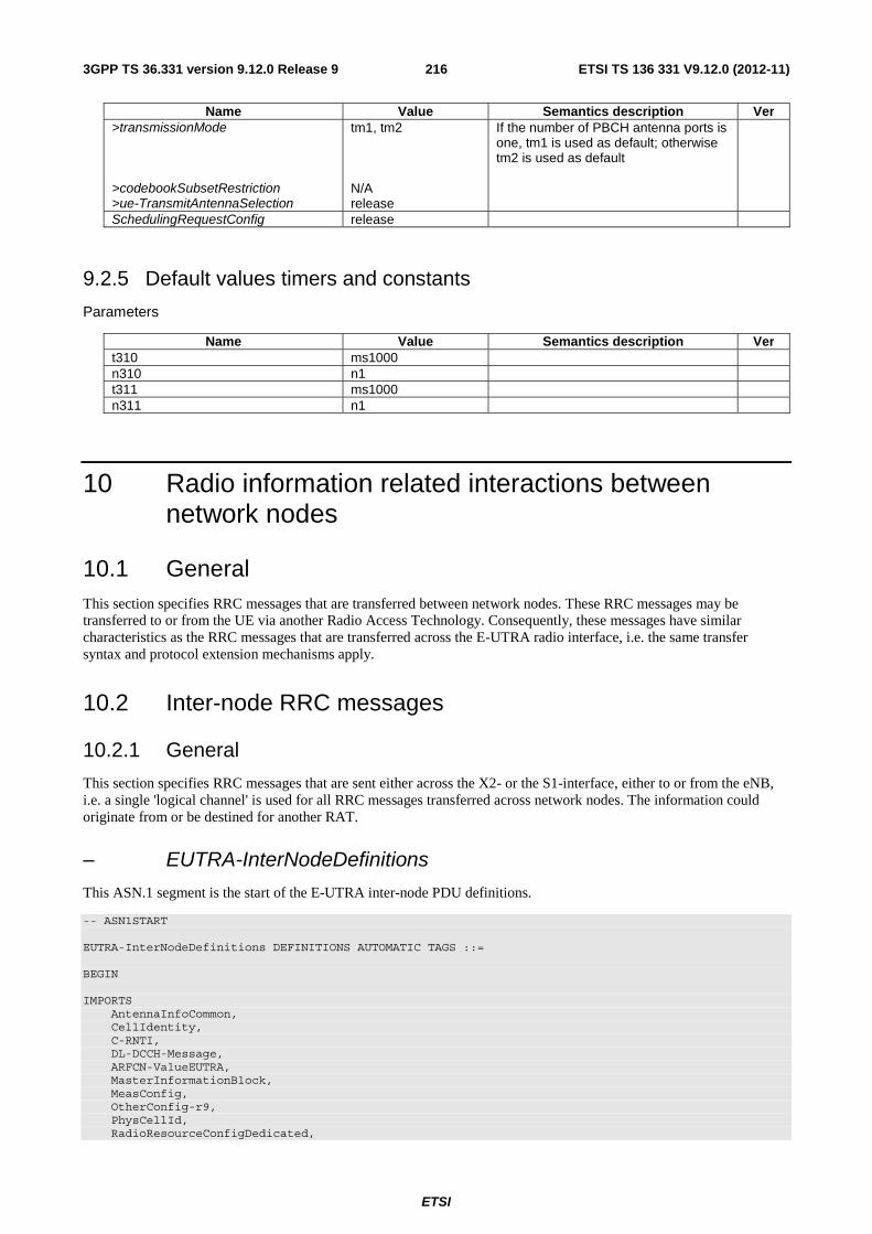
ETSI
ETSI TS 136 331 V9.12.0 (2012-11)2163GPP TS 36.331 version 9.12.0 Release 9
Name Value Semantics description Ver >transmissionMode >codebookSubsetRestriction >ue-TransmitAntennaSelection
tm1, tm2 N/A release
If the number of PBCH antenna ports is one, tm1 is used as default; otherwise tm2 is used as default
SchedulingRequestConfig release
9.2.5 Default values timers and constants
Parameters
Name Value Semantics description Ver t310 ms1000 n310 n1 t311 ms1000 n311 n1
10 Radio information related interactions between network nodes
10.1 General This section specifies RRC messages that are transferred between network nodes. These RRC messages may be transferred to or from the UE via another Radio Access Technology. Consequently, these messages have similar characteristics as the RRC messages that are transferred across the E-UTRA radio interface, i.e. the same transfer syntax and protocol extension mechanisms apply.
10.2 Inter-node RRC messages
10.2.1 General
This section specifies RRC messages that are sent either across the X2- or the S1-interface, either to or from the eNB, i.e. a single 'logical channel' is used for all RRC messages transferred across network nodes. The information could originate from or be destined for another RAT.
– EUTRA-InterNodeDefinitions
This ASN.1 segment is the start of the E-UTRA inter-node PDU definitions.
-- ASN1START EUTRA-InterNodeDefinitions DEFINITIONS AUTOMATIC TAGS ::= BEGIN IMPORTS AntennaInfoCommon, CellIdentity, C-RNTI, DL-DCCH-Message, ARFCN-ValueEUTRA, MasterInformationBlock, MeasConfig, OtherConfig-r9, PhysCellId, RadioResourceConfigDedicated,

ETSI
ETSI TS 136 331 V9.12.0 (2012-11)2173GPP TS 36.331 version 9.12.0 Release 9
SecurityAlgorithmConfig, ShortMAC-I, SystemInformationBlockType1, SystemInformationBlockType1-v890-IEs, SystemInformationBlockType2, UECapabilityInformation, UE-CapabilityRAT-ContainerList FROM EUTRA-RRC-Definitions; -- ASN1STOP
10.2.2 Message definitions
– HandoverCommand
This message is used to transfer the handover command generated by the target eNB, which is transparently transferred by the source RAN to the UE.
Direction: target eNB to source eNB/ source RAN
HandoverCommand message
-- ASN1START HandoverCommand ::= SEQUENCE { criticalExtensions CHOICE { c1 CHOICE{ handoverCommand-r8 HandoverCommand-r8-IEs, spare7 NULL, spare6 NULL, spare5 NULL, spare4 NULL, spare3 NULL, spare2 NULL, spare1 NULL }, criticalExtensionsFuture SEQUENCE {} } } HandoverCommand-r8-IEs ::= SEQUENCE { handoverCommandMessage OCTET STRING (CONTAINING DL-DCCH-Message), nonCriticalExtension SEQUENCE {} OPTIONAL } -- ASN1STOP
HandoverCommand field descriptions
handoverCommandMessage Contains the entire DL-DCCH-Message including the RRCConnectionReconfiguration message used to perform handover to E-UTRAN, generated (entirely) by the target eNB.
– HandoverPreparationInformation
This message is used to transfer the E-UTRA RRC information used by the target eNB during handover preparation, including UE capability information.
Direction: source eNB/ source RAN to target eNB
HandoverPreparationInformation message
-- ASN1START HandoverPreparationInformation ::= SEQUENCE { criticalExtensions CHOICE { c1 CHOICE{ handoverPreparationInformation-r8 HandoverPreparationInformation-r8-IEs, spare7 NULL, spare6 NULL, spare5 NULL, spare4 NULL, spare3 NULL, spare2 NULL, spare1 NULL

ETSI
ETSI TS 136 331 V9.12.0 (2012-11)2183GPP TS 36.331 version 9.12.0 Release 9
}, criticalExtensionsFuture SEQUENCE {} } } HandoverPreparationInformation-r8-IEs ::= SEQUENCE { ue-RadioAccessCapabilityInfo UE-CapabilityRAT-ContainerList, as-Config AS-Config OPTIONAL, -- Cond HO rrm-Config RRM-Config OPTIONAL, as-Context AS-Context OPTIONAL, -- Cond HO nonCriticalExtension HandoverPreparationInformation-v920-IEs OPTIONAL } HandoverPreparationInformation-v920-IEs ::= SEQUENCE { ue-ConfigRelease-r9 ENUMERATED { rel9, spare7, spare6, spare5, spare4, spare3, spare2, spare1, ...} OPTIONAL, -- Cond HO2 nonCriticalExtension SEQUENCE {} OPTIONAL } -- ASN1STOP
HandoverPreparationInformation field descriptions ue-RadioAccessCapabilityInfo E-UTRA radio access capabilities are always included and in case of inter-RAT handover to E-UTRA, UTRA radio access capabilities may be included. (If UTRA radio access capabilities are received from the source RAN, they are ignored by target eNB.) In case of inter-RAT handover to E-UTRA and the source is GERAN, GERAN capabilities are always included. as-Config The radio resource configuration. Applicable in case of intra-E-UTRA handover. If the target receives an incomplete MeasConfig and RadioResourceConfigDedicated in the as-Config, the target eNB may decide to apply the full configuration option based on the ue-ConfigRelease. rrm-Config Local E-UTRAN context used depending on the target node’s implementation, which is mainly used for the RRM purpose. as-Context Local E-UTRAN context required by the target eNB. ue-ConfigRelease Indicates the RRC protocol release applicable for the current UE configuration. This could be used by target eNB to decide if the full configuration approach should be used. If this field is not present, the target assumes that the current UE configuration is based on the release 8 version of RRC protocol. NOTE 1.
NOTE 1: The source typically sets the ue-ConfigRelease to the release corresponding with the current dedicated radio configuration. The source may however also consider the common radio resource configuration e.g. in case interoperability problems would appear if the UE temporary continues extensions of this part of the configuration in a target cell not supporting them.
Conditional presence Explanation HO The field is mandatory present in case of handover within E-UTRA; otherwise the field is
not present. HO2 The field is optional present in case of handover within E-UTRA; otherwise the field is not
present.
– UERadioAccessCapabilityInformation
This message is used to transfer UE radio access capability information, covering both upload to and download from the EPC.
Direction: eNB to/ from EPC
UERadioAccessCapabilityInformation message
-- ASN1START
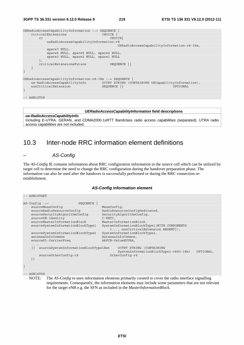
ETSI
ETSI TS 136 331 V9.12.0 (2012-11)2193GPP TS 36.331 version 9.12.0 Release 9
UERadioAccessCapabilityInformation ::= SEQUENCE { criticalExtensions CHOICE { c1 CHOICE{ ueRadioAccessCapabilityInformation-r8 UERadioAccessCapabilityInformation-r8-IEs, spare7 NULL, spare6 NULL, spare5 NULL, spare4 NULL, spare3 NULL, spare2 NULL, spare1 NULL }, criticalExtensionsFuture SEQUENCE {} } } UERadioAccessCapabilityInformation-r8-IEs ::= SEQUENCE { ue-RadioAccessCapabilityInfo OCTET STRING (CONTAINING UECapabilityInformation), nonCriticalExtension SEQUENCE {} OPTIONAL } -- ASN1STOP
UERadioAccessCapabilityInformation field descriptions ue-RadioAccessCapabilityInfo Including E-UTRA, GERAN, and CDMA2000-1xRTT Bandclass radio access capabilities (separated). UTRA radio access capabilities are not included.
10.3 Inter-node RRC information element definitions
– AS-Config
The AS-Config IE contains information about RRC configuration information in the source cell which can be utilized by target cell to determine the need to change the RRC configuration during the handover preparation phase. The information can also be used after the handover is successfully performed or during the RRC connection re-establishment.
AS-Config information element
-- ASN1START AS-Config ::= SEQUENCE { sourceMeasConfig MeasConfig, sourceRadioResourceConfig RadioResourceConfigDedicated, sourceSecurityAlgorithmConfig SecurityAlgorithmConfig, sourceUE-Identity C-RNTI, sourceMasterInformationBlock MasterInformationBlock, sourceSystemInformationBlockType1 SystemInformationBlockType1(WITH COMPONENTS {..., nonCriticalExtension ABSENT}), sourceSystemInformationBlockType2 SystemInformationBlockType2, antennaInfoCommon AntennaInfoCommon, sourceDl-CarrierFreq ARFCN-ValueEUTRA, ..., [[ sourceSystemInformationBlockType1Ext OCTET STRING (CONTAINING SystemInformationBlockType1-v890-IEs) OPTIONAL, sourceOtherConfig-r9 OtherConfig-r9 ]] } -- ASN1STOP
NOTE: The AS-Config re-uses information elements primarily created to cover the radio interface signalling requirements. Consequently, the information elements may include some parameters that are not relevant for the target eNB e.g. the SFN as included in the MasterInformationBlock.

ETSI
ETSI TS 136 331 V9.12.0 (2012-11)2203GPP TS 36.331 version 9.12.0 Release 9
AS-Config field descriptions
sourceMeasConfig
Measurement configuration in the source cell. The measurement configuration for all measurements existing in the source cell when handover is triggered shall be included. See 10.5.
sourceRadioResourceConfig
Radio configuration in the source cell. The radio resource configuration for all radio bearers existing in the source cell when handover is triggered shall be included. See 10.5.
sourceSecurityAlgorithmConfig
This field provides the AS integrity protection (SRBs) and AS ciphering (SRBs and DRBs) algorithm configuration used in the source cell.
sourceMasterInformationBlock MasterInformationBlock transmitted in the source cell.
sourceSystemInformationBlockType1
SystemInformationBlockType1 transmitted in the source cell.
sourceSystemInformationBlockType2 SystemInformationBlockType2 transmitted in the source cell.
antennaInfoCommon
This field provides information about the number of antenna ports in the source cell.
sourceDL-CarrierFreq
Provides the parameter Downlink EARFCN in the source cell, see TS 36.101 [42].
sourceOtherConfig
Provides other configuration in the source cell.
– AS-Context
The IE AS-Context is used to transfer local E-UTRAN context required by the target eNB.
AS-Context information element
-- ASN1START AS-Context ::= SEQUENCE { reestablishmentInfo ReestablishmentInfo OPTIONAL -- Cond HO } -- ASN1STOP
AS-Context field descriptions
reestablishmentInfo
Including information needed for the RRC connection re-establishment.
Conditional presence Explanation HO The field is mandatory present in case of handover within E-UTRA; otherwise the field is
not present.
– ReestablishmentInfo
The ReestablishmentInfo IE contains information needed for the RRC connection re-establishment.
ReestablishmentInfo information element
-- ASN1START ReestablishmentInfo ::= SEQUENCE { sourcePhysCellId PhysCellId, targetCellShortMAC-I ShortMAC-I, additionalReestabInfoList AdditionalReestabInfoList OPTIONAL,

ETSI
ETSI TS 136 331 V9.12.0 (2012-11)2213GPP TS 36.331 version 9.12.0 Release 9
... } AdditionalReestabInfoList ::= SEQUENCE ( SIZE (1..maxReestabInfo) ) OF AdditionalReestabInfo AdditionalReestabInfo ::= SEQUENCE{ cellIdentity CellIdentity, key-eNodeB-Star Key-eNodeB-Star, shortMAC-I ShortMAC-I } Key-eNodeB-Star ::= BIT STRING (SIZE (256)) -- ASN1STOP
ReestablishmentInfo field descriptions sourcePhyCellId The physical cell identity of the source cell, used to determine the UE context in the target eNB at re-establishment. targetCellShortMAC-I The ShortMAC-I for the handover target cell, in order for potential re-establishment to succeed. additionalReestabInfoList Contains a list of shortMAC-I and KeNB* for cells under control of the target eNB, required for potential re-establishment by the UE in these cells to succeed. Key-eNodeB-Star Parameter KeNB*: See TS 33.401 [32, 7.2.8.4]. This parameter is only used for X2 handover, and for S1 handover, it shall be ignored by target eNB.
– RRM-Config
The RRM-Config IE contains information about UE specific RRM information before the handover which can be utilized by target eNB after the handover is successfully performed.
RRM-Config information element
-- ASN1START RRM-Config ::= SEQUENCE { ue-InactiveTime ENUMERATED { s1, s2, s3, s5, s7, s10, s15, s20, s25, s30, s40, s50, min1, min1s20c, min1s40, min2, min2s30, min3, min3s30, min4, min5, min6, min7, min8, min9, min10, min12, min14, min17, min20, min24, min28, min33, min38, min44, min50, hr1, hr1min30, hr2, hr2min30, hr3, hr3min30, hr4, hr5, hr6, hr8, hr10, hr13, hr16, hr20, day1, day1hr12, day2, day2hr12, day3, day4, day5, day7, day10, day14, day19, day24, day30, dayMoreThan30} OPTIONAL, ... } -- ASN1STOP
RRM-Config field descriptions
ue-InactiveTime
Duration while UE has not received or transmitted any user data. Thus the timer is still running in case e.g., UE measures the neighbour cells for the HO purpose. Value s1 corresponds to 1 second, s2 corresponds to 2 seconds and so on. Value min1 corresponds to 1 minute, value min1s20 corresponds to 1 minute and 20 seconds, value min1s40 corresponds to 1 minute and 40 seconds and so on. Value hr1 corresponds to 1 hour, hr1min30 corresponds to 1 hour and 30 minutes and so on.

ETSI
ETSI TS 136 331 V9.12.0 (2012-11)2223GPP TS 36.331 version 9.12.0 Release 9
10.4 Inter-node RRC multiplicity and type constraint values
– Multiplicity and type constraints definitions -- ASN1START maxReestabInfo INTEGER ::= 32 -- Maximum number of KeNB* and shortMAC-I forwarded -- at handover for re-establishment preparation -- ASN1STOP
– End of EUTRA-InterNodeDefinitions -- ASN1START END -- ASN1STOP
10.5 Mandatory information in AS-Config The AS-Config transferred between source eNB and target-eNB shall include all IEs necessary to describe the AS context. The conditional presence in section 6 is only applicable for eNB to UE communication.
The "need" or "cond" statements are not applied in case of sending the IEs from source eNB to target eNB. Some information elements shall be included regardless of the "need" or "cond" e.g. discardTimer. The AS-Config re-uses information elements primarily created to cover the radio interface signalling requirements. The information elements may include some parameters that are not relevant for the target eNB e.g. the SFN as included in the MasterInformationBlock.
Within the sourceRadioResourceConfig the source eNB shall include fields that are optional for eNB to UE communication, if the functionality is configured unless explictly specified otherwise in the following:
- in accordance with a condition that is explictly stated to be applicable; or
- a default value is defined for the concerned field; and the configured value is the same as the default value that is defined; or
- the need of the field is OP and the current UE configuration corresponds with the behaviour defined for absence of the field;

ETSI
ETSI TS 136 331 V9.12.0 (2012-11)2233GPP TS 36.331 version 9.12.0 Release 9
Name Presence in clause 6 Comment RadioResourceConfigDedicated > srb-ToAddModList >> rlc-Config >> logicalChannelConfig >>> ul-SpecificParameters >>>> logicalChannelGroup >>> logicalChannelSR-Mask-r9
OPTIONAL, -Cond HO-Conn OPTIONAL, -Cond Setup OPTIONAL, -Cond Setup OPTIONAL, -Cond UL OPTIONAL, -Need OR OPTIONAL, -Cond SRmask
- - - - The conditional presence applies - - The conditional presence applies
>drb-ToAddModList >> eps-BearerIdentity >> pdcp-Config >>> discardTimer >>> rlc-AM >>> rlc-UM >> rlc-Config >> logicalChannelIdentity >> logicalChannelConfig >>> ul-SpecificParameters >>>> logicalChannelGroup >>> logicalChannelSR-Mask-r9
OPTIONAL, -Cond HO-toEUTRA OPTIONAL, -Cond DRB-Setup OPTIONAL, -Cond PDCP OPTIONAL, -Cond Setup OPTIONAL, -Cond Rlc-AM OPTIONAL, -Cond Rlc-UM OPTIONAL, -Cond Setup OPTIONAL, -Cond DRB-Setup OPTIONAL, -Cond Setup OPTIONAL, -Cond UL OPTIONAL, -Need OR OPTIONAL, -Cond SRmask
- - - - - The conditional presence applies - The conditional presence applies - - - - The conditional presence applies - - The conditional presence applies
> mac-MainConfig >> ul-SCH-Config >>> maxHARQ-Tx >> periodicBSR-Timer >> drx-Config >>> shortDRX >> phr-Config >> sr-ProhibitTimer
OPTIONAL, -Need ON OPTIONAL, -Need ON OPTIONAL, -Need ON OPTIONAL, -Need ON OPTIONAL, -Need ON OPTIONAL, -Need OR OPTIONAL, -Need ON OPTIONAL, -Need ON
- - - - - - - -
> sps-Config >> sps-ConfigDL >> sps-ConfigUL >>> p0-Persistent >>> twoIntervalsConfig
OPTIONAL, -Need ON OPTIONAL, -Need ON OPTIONAL, -Need ON OPTIONAL, -Need OP OPTIONAL, -Cond TDD
- - - - - The conditional presence applies
> physicalConfigDedicated >> pdsch-ConfigDedicated >> pucch-ConfigDedicated >>> tdd-AckNackFeedbackMode >> pusch-ConfigDedicated >> uplinkPowerControlDedicated >> tpc-PDCCH-ConfigPUCCH >> tpc-PDCCH-ConfigPUSCH >> cqi-ReportConfig >>> cqi-ReportingModeAperiodic >>> cqi-ReportPeriodic >> soundingRS-UL-ConfigDedicated >> antennaInfo >>> codebookSubsetRestriction >> schedulingRequestConfig >physicalConfigDedicated-v920 >> cqi-ReportConfig-v920 >>> cqi-Mask-r9 >>> pmi-RI-Report-r9 >> antennaInfo-v920 >>> codebookSubsetRestriction-v920
OPTIONAL, -Need ON OPTIONAL, -Need ON OPTIONAL, -Need ON OPTIONAL, -Cond TDD OPTIONAL, -Need ON OPTIONAL, -Need ON OPTIONAL, -Need ON OPTIONAL, -Need ON OPTIONAL, -Need ON OPTIONAL, -Need OR OPTIONAL, -Need ON OPTIONAL, -Need ON OPTIONAL, -Need ON OPTIONAL, -Cond TM OPTIONAL, -Need ON OPTIONAL, -Need ON OPTIONAL, -Need ON OPTIONAL, -Cond cqi-Setup OPTIONAL, -Cond PMIRI OPTIONAL, -Need ON OPTIONAL, -Cond TM8
- - - - The conditional presence applies - - - - - - - - - - The conditional presence applies - - - - The conditional presence applies - The conditional presence applies - - The conditional presence applies
> rlf-TimersAndConstants-r9 OPTIONAL, -Need ON -
For the measurement configuration, a corresponding operation as 5.5.6.1 is executed by target eNB.
Within the sourceMeasConfig the source eNB shall include fields that are optional for eNB to UE communication, if the functionality is configured unless explicitly specified otherwise in the following:
- in accordance with a condition that is explicitly stated to be applicable; or
- a default value is defined for the concerned field; and the configured value is the same as the default value that is defined; or

ETSI
ETSI TS 136 331 V9.12.0 (2012-11)2243GPP TS 36.331 version 9.12.0 Release 9
- the need of the field is OP and the current UE configuration corresponds with the behaviour defined for absence of the field;
Name Presence in clause 6 Comment MeasConfig > measObjectToAddModList >> measObject >>> measObjectEUTRA >>>> cellsToAddModList >>>> blackCellsToAddModList >>>> cellForWhichToReportCGI >>> MeasObjectUTRA >>>> cellsToAddModList >>>> cellForWhichToReportCGI >>>> csg-allowedReportingCells-v930 >>> MeasObjectGERAN >>>> cellForWhichToReportCGI >>> MeasObjectCDMA2000 >>>> searchWindowSize >>>> cellsToAddModList >>>> cellForWhichToReportCGI
OPTIONAL, -Need ON - - OPTIONAL, -Need ON OPTIONAL, -Need ON OPTIONAL, -Need ON - OPTIONAL, -Need ON OPTIONAL, -Need ON OPTIONAL, -Need ON - OPTIONAL, -Need ON - OPTIONAL, -Need ON OPTIONAL, -Need ON OPTIONAL, -Need ON
- - - - - - - - - - - - - - -
> reportConfigToAddModList OPTIONAL, -Need ON - > measIdToAddModList OPTIONAL, -Need ON - > quantityConfig >> quantityConfigEUTRA >> quantityConfigUTRA >> quantityConfigGERAN >> quantityConfigCDMA2000
OPTIONAL, -Need ON OPTIONAL, -Need ON OPTIONAL, -Need ON OPTIONAL, -Need ON OPTIONAL, -Need ON
- - - - -
> s-Measure OPTIONAL, -Need ON - > preRegistrationInfoHRPD >> preRegistrationZoneId >> secondaryPreRegistrationZoneIdList
OPTIONAL, -Need OP OPTIONAL, -Cond PreRegAllowed OPTIONAL, -Need OR
- The conditional presence applies -
> speedStatePars OPTIONAL, -Need ON -
Within the sourceOtherConfig the source eNB shall include fields that are optional for eNB to UE communication, if the functionality is configured unless explicitly specified otherwise in the following:
- in accordance with a condition that is explicitly stated to be applicable; or
- a default value is defined for the concerned field; and the configured value is the same as the default value that is defined; or
- the need of the field is OP and the current UE configuration corresponds with the behaviour defined for absence of the field;
Name Presence in clause 6 Comment OtherConfig > reportProximityConfig-r9 OPTIONAL, -Need ON -
11 UE capability related constraints and performance requirements
11.1 UE capability related constraints The following table lists constraints regarding the UE capabilities that E-UTRAN is assumed to take into account.

ETSI
ETSI TS 136 331 V9.12.0 (2012-11)2253GPP TS 36.331 version 9.12.0 Release 9
Parameter Description Value #DRBs The number of DRBs that a UE of categories 1- 5 shall support 8 #RLC-AM The number of RLC AM entities that a UE of categories 1- 5
shall support 10
#minCellperMeasObjectEUTRA
The minimum number of neighbour cells (excluding black list cells) that a UE shall be able to store within a MeasObjectEUTRA
32
#minBlackCellRangesperMeasObjectEUTRA
The minimum number of blacklist cell PCI ranges that a UE shall be able to store within a MeasObjectEUTRA
32
#minCellperMeasObjectUTRA
The minimum number of neighbour cells that a UE shall be able to store within a MeasObjectUTRA
32
#minCellperMeasObjectGERAN
The minimum number of neighbour cells that a UE shall be able to store within a measObjectGERAN
32
#minCellperMeasObjectCDMA2000
The minimum number of neighbour cells that a UE shall be able to store within a measObjectCDMA2000
32
#minCellTotal The minimum number of neighbour cells (excluding black list cells) that UE shall be able to store in total in all measurement objects configured
256
11.2 Processing delay requirements for RRC procedures The UE performance requirements for RRC procedures are specified in the following table, by means of a value N:
N = the number of 1ms subframes from the end of reception of the E-UTRAN -> UE message on the UE physical layer up to when the UE shall be ready for the reception of uplink grant for the UE -> E-UTRAN response message with no access delay other than the TTI-alignment (e.g. excluding delays caused by scheduling, the random access procedure or physical layer synchronisation).
Figure 11.2-1: Illustration of RRC procedure delay

ETSI
ETSI TS 136 331 V9.12.0 (2012-11)2263GPP TS 36.331 version 9.12.0 Release 9
Procedure title: E-UTRAN -> UE UE -> E-UTRAN N Notes RRC Connection Control Procedures RRC connection establishment
RRCConnectionSetup
RRCConnectionSetupComplete
15
RRC connection release
RRCConnectionRelease
NA
RRC connection re-configuration (radio resource configuration)
RRCConnectionReconfiguration
RRCConnectionReconfigurationComplete
15
RRC connection re-configuration (measurement configuration)
RRCConnectionReconfiguration
RRCConnectionReconfigurationComplete
15
RRC connection re-configuration (intra-LTE mobility)
RRCConnectionReconfiguration
RRCConnectionReconfigurationComplete
15
RRC connection re-establishment
RRCConnectionReestablishment
RRCConnectionReestablishmentComplete
15
Initial security activation
SecurityModeCommand
SecurityModeCommandComplete/SecurityModeCommandFailure
10
Initial security activation + RRC connection re-configuration (RB establishment)
SecurityModeCommand, RRCConnectionReconfiguration
RRCConnectionReconfigurationComplete
20 The two DL messages are transmitted in the same TTI
Paging Paging NA
Inter RAT mobility Handover to E-UTRA RRCConnectionReco
nfiguration (sent by other RAT)
RRCConnectionReconfigurationComplete
NA The performance of this procedure is specified in [50] in case of handover from GSM and [29], [30] in case of handover from UTRA.
Handover from E-UTRA
MobilityFromEUTRACommand
NA The performance of this procedure is specified in [16]
Handover from E-UTRA to CDMA2000
HandoverFromEUTRAPreparationRequest (CDMA2000)
NA Used to trigger the handover preparation procedure with a CDMA2000 RAT. The performance of this procedure is specified in [16]
Measurement procedures Measurement Reporting
MeasurementReport NA
Other procedures UE capability transfer UECapabilityEnquiry UECapabilityInformation 10 Counter check CounterCheck CounterCheckResponse 10 Proximity indication ProximityIndication NA UE information UEInformationReque
st UEInformationResponse 15

ETSI
ETSI TS 136 331 V9.12.0 (2012-11)2273GPP TS 36.331 version 9.12.0 Release 9
11.3 Void
ETSI
ETSI TS 136 331 V9.12.0 (2012-11)2283GPP TS 36.331 version 9.12.0 Release 9
Annex A (informative): Guidelines, mainly on use of ASN.1
Editor's note No agreements have been reached concerning the extension of RRC PDUs so far. Any statements in this section about the protocol extension mechanism should be considered as FFS.
A.1 Introduction The following clauses contain guidelines for the specification of RRC protocol data units (PDUs) with ASN.1.
A.2 Procedural specification
A.2.1 General principles
The procedural specification provides an overall high level description regarding the UE behaviour in a particular scenario.
It should be noted that most of the UE behaviour associated with the reception of a particular field is covered by the applicable parts of the PDU specification. The procedural specification may also include specific details of the UE behaviour upon reception of a field, but typically this should be done only for cases that are not easy to capture in the PDU section e.g. general actions, more complicated actions depending on the value of multiple fields.
Likewise, the procedural specification need not specify the UE requirements regarding the setting of fields within the messages that are send to E-UTRAN i.e. this may also be covered by the PDU specification.
A.2.2 More detailed aspects
The following more detailed conventions should be used:
- Bullets:
- Capitals should be used in the same manner as in other parts of the procedural text i.e. in most cases no capital applies since the bullets are part of the sentence starting with 'The UE shall:'
- All bullets, including the last one in a sub-clause, should end with a semi-colon i.e. an ';'
- Conditions
- Whenever multiple conditions apply, a semi-colon should be used at the end of each conditions with the exception of the last one, i.e. as in 'if cond1; or cond2:
A.3 PDU specification
A.3.1 General principles
A.3.1.1 ASN.1 sections
The RRC PDU contents are formally and completely described using abstract syntax notation (ASN.1), see X.680 [13], X.681 (02/2002) [14].
The complete ASN.1 code is divided into a number of ASN.1 sections in the specifications. In order to facilitate the extraction of the complete ASN.1 code from the specification, each ASN.1 section begins with a text paragraph consisting entirely of an ASN.1 start tag, which consists of a double hyphen followed by a single space and the text string "ASN1START" (in all upper case letters). Each ASN.1 section ends with a text paragraph consisting entirely of
ETSI
ETSI TS 136 331 V9.12.0 (2012-11)2293GPP TS 36.331 version 9.12.0 Release 9
an ASN.1 stop tag, which consists of a double hyphen followed by a single space and the text "ASN1STOP" (in all upper case letters):
-- ASN1START -- ASN1STOP
The text paragraphs containing the ASN.1 start and stop tags should not contain any ASN.1 code significant for the complete description of the RRC PDU contents. The complete ASN.1 code may be extracted by copying all the text paragraphs between an ASN.1 start tag and the following ASN.1 stop tag in the order they appear, throughout the specification.
NOTE: A typical procedure for extraction of the complete ASN.1 code consists of a first step where the entire RRC PDU contents description (ultimately the entire specification) is saved into a plain text (ASCII) file format, followed by a second step where the actual extraction takes place, based on the occurrence of the ASN.1 start and stop tags.
A.3.1.2 ASN.1 identifier naming conventions
The naming of identifiers (i.e., the ASN.1 field and type identifiers) should be based on the following guidelines:
- Message (PDU) identifiers should be ordinary mixed case without hyphenation. These identifiers, e.g., the RRCConnectionModificationCommand, should be used for reference in the procedure text. Abbreviated forms of these identifiers should not be used.
- Type identifiers other than PDU identifiers should be ordinary mixed case, with hyphenation used to set off acronyms only where an adjacent letter is a capital, e.g., EstablishmentCause, SelectedPLMN (not Selected-PLMN, since the "d" in "Selected" is lowercase), InitialUE-Identity and MeasSFN-SFN-TimeDifference.
- Field identifiers shall start with a lowercase letter and use mixed case thereafter, e.g., establishmentCause. If a field identifier begins with an acronym (which would normally be in upper case), the entire acronym is lowercase (plmn-Identity, not pLMN-Identity). The acronym is set off with a hyphen (ue-Identity, not ueIdentity), in order to facilitate a consistent search pattern with corresponding type identifiers.
- Identifiers that are likely to be keywords of some language, especially widely used languages, such as C++ or Java, should be avoided to the extent possible.
- Identifiers, other than PDU identifiers, longer than 25 characters should be avoided where possible. It is recommended to use abbreviations, which should be done in a consistent manner i.e. use 'Meas' instead of 'Measurement' for all occurrences. Examples of typical abbreviations are given in table A.3.1.2.1-1 below.
- For future extension: When an extension is introduced a suffix is added to the identifier of the concerned ASN.1 field and/ or type. A suffix of the form "-rX" is used, with X indicating the release, for ASN.1 fields or types introduced in a later release (i.e. a release later than the original/ first release of the protocol) as well as for ASN.1 fields or types for which a revision is introduced in a later release replacing a previous version, e.g., Foo-r9 for the Rel-9 version of the ASN.1 type Foo. A suffix of the form "-vXYZ" is used for ASN.1 fields or types that only are an extension of a corresponding earlier field or type (see sub-clause A.4), e.g., AnElement-v10b0 for the extension of the ASN.1 type AnElement introduced in version 10.11.0 of the specification. A number 0...9, 10, 11, etc. is used to represent the first part of the version number, indicating the release of the protocol. Lower case letters a, b, c, etc. are used to represent the second (and third) part of the version number if they are greater than 9. In the procedural specification, in field descriptions as well as in headings suffices are not used, unless there is a clear need to distinguish the extension from the original field.
- More generally, in case there is a need to distinguish different variants of an ASN.1 field or IE, a suffix should be added at the end of the identifiers e.g. MeasObjectUTRAN, ConfigCommon. When there is no particular need to distinguish the fields (e.g. because the field is included in different IEs), a common field identifier name may be used. This may be attractive e.g. in case the procedural specification is the same for the different variants.

ETSI
ETSI TS 136 331 V9.12.0 (2012-11)2303GPP TS 36.331 version 9.12.0 Release 9
Table A.3.1.2-1: Examples of typical abbreviations used in ASN.1 identifiers
Abbreviation Abbreviated word Conf Confirmation Config Configuration DL Downlink Freq Frequency Id Identity Ind Indication Info Information Meas Measurement Neigh Neighbour(ing) Param(s) Parameter(s) Persist Persistent Phys Physical Reestab Reestablishment Req Request Sched Scheduling Thresh Threshold Transm Transmission UL Uplink
NOTE: The table A.3.1.2.1-1 is not exhaustive. Additional abbreviations may be used in ASN.1 identifiers when needed.
A.3.1.3 Text references using ASN.1 identifiers
A text reference into the RRC PDU contents description from other parts of the specification is made using the ASN.1 field or type identifier of the referenced element. The ASN.1 field and type identifiers used in text references should be in the italic font style. The "do not check spelling and grammar" attribute in Word should be set. Quotation marks (i.e., " ") should not be used around the ASN.1 field or type identifier.
A reference to an RRC PDU type should be made using the corresponding ASN.1 type identifier followed by the word "message", e.g., a reference to the RRCConnectionRelease message.
A reference to a specific part of an RRC PDU, or to a specific part of any other ASN.1 type, should be made using the corresponding ASN.1 field identifier followed by the word "field", e.g., a reference to the prioritisedBitRate field in the example below.
-- /example/ ASN1START LogicalChannelConfig ::= SEQUENCE { ul-SpecificParameters SEQUENCE { priority Priority, prioritisedBitRate PrioritisedBitRate, bucketSizeDuration BucketSizeDuration, logicalChannelGroup INTEGER (0..3) } OPTIONAL } -- ASN1STOP
NOTE: All the ASN.1 start tags in the ASN.1 sections, used as examples in this annex to the specification, are deliberately distorted, in order not to include them when the ASN.1 description of the RRC PDU contents is extracted from the specification.
A reference to a specific type of information element should be made using the corresponding ASN.1 type identifier preceded by the acronym "IE", e.g., a reference to the IE LogicalChannelConfig in the example above.
References to a specific type of information element should only be used when those are generic, i.e., without regard to the particular context wherein the specific type of information element is used. If the reference is related to a particular context, e.g., an RRC PDU type (message) wherein the information element is used, the corresponding field identifier in that context should be used in the text reference.

ETSI
ETSI TS 136 331 V9.12.0 (2012-11)2313GPP TS 36.331 version 9.12.0 Release 9
A reference to a specific value of an ASN.1 field should be made using the corresponding ASN.1 value while using quotation marks (i.e., " ") around the ASN.1 value, e.g., 'if the status field is set to value "true"'.
A.3.2 High-level message structure
Within each logical channel type, the associated RRC PDU (message) types are alternatives within a CHOICE, as shown in the example below.
-- /example/ ASN1START DL-DCCH-Message ::= SEQUENCE { message DL-DCCH-MessageType } DL-DCCH-MessageType ::= CHOICE { c1 CHOICE { dlInformationTransfer DLInformationTransfer, handoverFromEUTRAPreparationRequest HandoverFromEUTRAPreparationRequest, mobilityFromEUTRACommand MobilityFromEUTRACommand, rrcConnectionReconfiguration RRCConnectionReconfiguration, rrcConnectionRelease RRCConnectionRelease, securityModeCommand SecurityModeCommand, ueCapabilityEnquiry UECapabilityEnquiry, spare1 NULL }, messageClassExtension SEQUENCE {} } -- ASN1STOP
A nested two-level CHOICE structure is used, where the alternative PDU types are alternatives within the inner level c1 CHOICE.
Spare alternatives (i.e., spare1 in this case) may be included within the c1 CHOICE to facilitate future extension. The number of such spare alternatives should not extend the total number of alternatives beyond an integer-power-of-two number of alternatives (i.e., eight in this case).
Further extension of the number of alternative PDU types is facilitated using the messageClassExtension alternative in the outer level CHOICE.
A.3.3 Message definition
Each PDU (message) type is specified in an ASN.1 section similar to the one shown in the example below.
-- /example/ ASN1START RRCConnectionReconfiguration ::= SEQUENCE { rrc-TransactionIdentifier RRC-TransactionIdentifier, criticalExtensions CHOICE { c1 CHOICE{ rrcConnectionReconfiguration-r8 RRCConnectionReconfiguration-r8-IEs, spare3 NULL, spare2 NULL, spare1 NULL }, criticalExtensionsFuture SEQUENCE {} } } RRCConnectionReconfiguration-r8-IEs ::= SEQUENCE { -- Enter the IEs here. ... } -- ASN1STOP
Hooks for critical and non-critical extension should normally be included in the PDU type specification. How these hooks are used is further described in sub-clause A.4.
Critical extensions are characterised by a redefinition of the PDU contents and need to be governed by a mechanism for protocol version agreement between the encoder and the decoder of the PDU, such that the encoder is prevented from sending a critically extended version of the PDU type, which is not comprehended by the decoder.
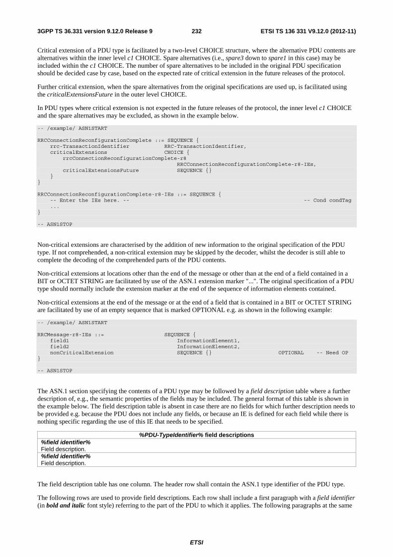
ETSI
ETSI TS 136 331 V9.12.0 (2012-11)2323GPP TS 36.331 version 9.12.0 Release 9
Critical extension of a PDU type is facilitated by a two-level CHOICE structure, where the alternative PDU contents are alternatives within the inner level c1 CHOICE. Spare alternatives (i.e., spare3 down to spare1 in this case) may be included within the c1 CHOICE. The number of spare alternatives to be included in the original PDU specification should be decided case by case, based on the expected rate of critical extension in the future releases of the protocol.
Further critical extension, when the spare alternatives from the original specifications are used up, is facilitated using the criticalExtensionsFuture in the outer level CHOICE.
In PDU types where critical extension is not expected in the future releases of the protocol, the inner level c1 CHOICE and the spare alternatives may be excluded, as shown in the example below.
-- /example/ ASN1START RRCConnectionReconfigurationComplete ::= SEQUENCE { rrc-TransactionIdentifier RRC-TransactionIdentifier, criticalExtensions CHOICE { rrcConnectionReconfigurationComplete-r8 RRCConnectionReconfigurationComplete-r8-IEs, criticalExtensionsFuture SEQUENCE {} } } RRCConnectionReconfigurationComplete-r8-IEs ::= SEQUENCE { -- Enter the IEs here. -- -- Cond condTag ... } -- ASN1STOP
Non-critical extensions are characterised by the addition of new information to the original specification of the PDU type. If not comprehended, a non-critical extension may be skipped by the decoder, whilst the decoder is still able to complete the decoding of the comprehended parts of the PDU contents.
Non-critical extensions at locations other than the end of the message or other than at the end of a field contained in a BIT or OCTET STRING are facilitated by use of the ASN.1 extension marker "...". The original specification of a PDU type should normally include the extension marker at the end of the sequence of information elements contained.
Non-critical extensions at the end of the message or at the end of a field that is contained in a BIT or OCTET STRING are facilitated by use of an empty sequence that is marked OPTIONAL e.g. as shown in the following example:
-- /example/ ASN1START RRCMessage-r8-IEs ::= SEQUENCE { field1 InformationElement1, field2 InformationElement2, nonCriticalExtension SEQUENCE {} OPTIONAL -- Need OP } -- ASN1STOP
The ASN.1 section specifying the contents of a PDU type may be followed by a field description table where a further description of, e.g., the semantic properties of the fields may be included. The general format of this table is shown in the example below. The field description table is absent in case there are no fields for which further description needs to be provided e.g. because the PDU does not include any fields, or because an IE is defined for each field while there is nothing specific regarding the use of this IE that needs to be specified.
%PDU-TypeIdentifier% field descriptions %field identifier% Field description. %field identifier% Field description.
The field description table has one column. The header row shall contain the ASN.1 type identifier of the PDU type.
The following rows are used to provide field descriptions. Each row shall include a first paragraph with a field identifier (in bold and italic font style) referring to the part of the PDU to which it applies. The following paragraphs at the same

ETSI
ETSI TS 136 331 V9.12.0 (2012-11)2333GPP TS 36.331 version 9.12.0 Release 9
row may include (in regular font style), e.g., semantic description, references to other specifications and/ or specification of value units, which are relevant for the particular part of the PDU.
The parts of the PDU contents that do not require a field description shall be omitted from the field description table.
A.3.4 Information elements
Each IE (information element) type is specified in an ASN.1 section similar to the one shown in the example below.
-- /example/ ASN1START PRACH-ConfigSIB ::= SEQUENCE { rootSequenceIndex INTEGER (0..1023), prach-ConfigInfo PRACH-ConfigInfo } PRACH-Config ::= SEQUENCE { rootSequenceIndex INTEGER (0..1023), prach-ConfigInfo PRACH-ConfigInfo OPTIONAL -- Need ON } PRACH-ConfigInfo ::= SEQUENCE { prach-ConfigIndex ENUMERATED {ffs}, highSpeedFlag ENUMERATED {ffs}, zeroCorrelationZoneConfig ENUMERATED {ffs} } -- ASN1STOP
IEs should be introduced whenever there are multiple fields for which the same set of values apply. IEs may also be defined for other reasons e.g. to break down a ASN.1 definition in to smaller pieces.
A group of closely related IE type definitions, like the IEs PRACH-ConfigSIB and PRACH-Config in this example, are preferably placed together in a common ASN.1 section. The IE type identifiers should in this case have a common base, defined as the generic type identifier. It may be complemented by a suffix to distinguish the different variants. The "PRACH-Config" is the generic type identifier in this example, and the "SIB" suffix is added to distinguish the variant. The sub-clause heading and generic references to a group of closely related IEs defined in this way should use the generic type identifier.
The same principle should apply if a new version, or an extension version, of an existing IE is created for critical or non-critical extension of the protocol (see sub-clause A.4). The new version, or the extension version, of the IE is included in the same ASN.1 section defining the original. A suffix is added to the type identifier, using the naming conventions defined in sub-clause A.3.1.2, indicating the release or version of the where the new version, or extension version, was introduced.
Local IE type definitions, like the IE PRACH-ConfigInfo in the example above, may be included in the ASN.1 section and be referenced in the other IE types defined in the same ASN.1 section. The use of locally defined IE types should be encouraged, as a tool to break up large and complex IE type definitions. It can improve the readability of the code. There may also be a benefit for the software implementation of the protocol end-points, as these IE types are typically provided by the ASN.1 compiler as independent data elements, to be used in the software implementation.
An IE type defined in a local context, like the IE PRACH-ConfigInfo, should not be referenced directly from other ASN.1 sections in the RRC specification. An IE type which is referenced in more than one ASN.1 section should be defined in a separate sub-clause, with a separate heading and a separate ASN.1 section (possibly as one in a set of closely related IE types, like the IEs PRACH-ConfigSIB and PRACH-Config in the example above). Such IE types are also referred to as 'global IEs'.
NOTE: Referring to an IE type, that is defined as a local IE type in the context of another ASN.1 section, does not generate an ASN.1 compilation error. Nevertheless, using a locally defined IE type in that way makes the IE type definition difficult to find, as it would not be visible at an outline level of the specification. It should be avoided.
The ASN.1 section specifying the contents of one or more IE types, like in the example above, may be followed by a field description table, where a further description of, e.g., the semantic properties of the fields of the information elements may be included. This table may be absent, similar as indicated in sub-clause A.3.3 for the specification of the

ETSI
ETSI TS 136 331 V9.12.0 (2012-11)2343GPP TS 36.331 version 9.12.0 Release 9
PDU type. The general format of the field description table is the same as shown in sub-clause A.3.3 for the specification of the PDU type.
A.3.5 Fields with optional presence
A field with optional presence may be declared with the keyword DEFAULT. It identifies a default value to be assumed, if the sender does not include a value for that field in the encoding:
-- /example/ ASN1START PreambleInfo ::= SEQUENCE { numberOfRA-Preambles INTEGER (1..64) DEFAULT 1, ... } -- ASN1STOP
Alternatively, a field with optional presence may be declared with the keyword OPTIONAL. It identifies a field for which a value can be omitted. The omission carries semantics, which is different from any normal value of the field:
-- /example/ ASN1START PRACH-Config ::= SEQUENCE { rootSequenceIndex INTEGER (0..1023), prach-ConfigInfo PRACH-ConfigInfo OPTIONAL -- Need ON } -- ASN1STOP
The semantics of an optionally present field, in the case it is omitted, should be indicated at the end of the paragraph including the keyword OPTIONAL, using a short comment text with a need statement. The need statement includes the keyword "Need", followed by one of the predefined semantics tags (OP, ON or OR) defined in sub-clause 6.1. If the semantics tag OP is used, the semantics of the absent field are further specified either in the field description table following the ASN.1 section, or in procedure text.
A.3.6 Fields with conditional presence
A field with conditional presence is declared with the keyword OPTIONAL. In addition, a short comment text shall be included at the end of the paragraph including the keyword OPTIONAL. The comment text includes the keyword "Cond", followed by a condition tag associated with the field ("UL" in this example):
-- /example/ ASN1START LogicalChannelConfig ::= SEQUENCE { ul-SpecificParameters SEQUENCE { priority INTEGER (0), ... } OPTIONAL -- Cond UL } -- ASN1STOP
When conditionally present fields are included in an ASN.1 section, the field description table after the ASN.1 section shall be followed by a conditional presence table. The conditional presence table specifies the conditions for including the fields with conditional presence in the particular ASN.1 section.
Conditional presence Explanation UL Specification of the conditions for including the field associated with the condition
tag = "UL". Semantics in case of optional presence under certain conditions may also be specified.
The conditional presence table has two columns. The first column (heading: "Conditional presence") contains the condition tag (in italic font style), which links the fields with a condition tag in the ASN.1 section to an entry in the table. The second column (heading: "Explanation") contains a text specification of the conditions and requirements for

ETSI
ETSI TS 136 331 V9.12.0 (2012-11)2353GPP TS 36.331 version 9.12.0 Release 9
the presence of the field. The second column may also include semantics, in case of an optional presence of the field, under certain conditions i.e. using the same predefined tags as defined for optional fields in A.3.5.
Conditional presence should primarily be used when presence of a field despends on the presence and/ or value of other fields within the same message. If the presence of a field depends on whether another feature/ function function has been configured, while this function can be configured indepedantly e.g. by another message and/ or at another point in time, the relation is best reflected by means of a statement in the field description table.
If the ASN.1 section does not include any fields with conditional presence, the conditional presence table shall not be included.
Whenever a field is only applicable in specific cases e.g. TDD, use of conditional presence should be considered.
A.3.7 Guidelines on use of lists with elements of SEQUENCE type
Where an information element has the form of a list (the SEQUENCE OF construct in ASN.1) with the type of the list elements being a SEQUENCE data type, an information element shall be defined for the list elements even if it would not otherwise be needed.
For example, a list of PLMN identities with reservation flags is defined as in the following example:
-- /example/ ASN1START PLMN-IdentityInfoList ::= SEQUENCE (SIZE (1..6)) OF PLMN-IdentityInfo PLMN-IdentityInfo ::= SEQUENCE { plmn-Identity PLMN-Identity, cellReservedForOperatorUse ENUMERATED {reserved, notReserved} } -- ASN1STOP
rather than as in the following (bad) example, which may cause generated code to contain types with unpredictable names:
-- /bad example/ ASN1START PLMN-IdentityList ::= SEQUENCE (SIZE (1..6)) OF SEQUENCE { plmn-Identity PLMN-Identity, cellReservedForOperatorUse ENUMERATED {reserved, notReserved} } -- ASN1STOP
A.4 Extension of the PDU specifications
A.4.1 General principles to ensure compatibility
It is essential that extension of the protocol does not affect interoperability i.e. it is essential that implementations based on different versions of the RRC protocol are able to interoperate. In particular, this requirement applies for the following kind of protocol extensions:
- Introduction of new PDU types (i.e. these should not cause unexpected behaviour or damage).
- Introduction of additional fields in an extensible PDUs (i.e. it should be possible to ignore uncomprehended extensions without affecting the handling of the other parts of the message).
- Introduction of additional values of an extensible field of PDUs. If used, the behaviour upon reception of an uncomprehended value should be defined.
It should be noted that the PDU extension mechanism may depend on the logical channel used to transfer the message e.g. for some PDUs an implementation may be aware of the protocol version of the peer in which case selective ignoring of extensions may not be required.

ETSI
ETSI TS 136 331 V9.12.0 (2012-11)2363GPP TS 36.331 version 9.12.0 Release 9
The non-critical extension mechanism is the primary mechanism for introducing protocol extensions i.e. the critical extension mechanism is used merely when there is a need to introduce a 'clean' message version. Such a need appears when the last message version includes a large number of non-critical extensions, which results in issues like readability, overhead associated with the extension markers. The critical extension mechanism may also be considered when it is complicated to accomodate the extensions by means of non-critical extension mechanisms.
A.4.2 Critical extension of messages
The mechanisms to critically extend a message are defined in A.3.3. There are both "outer branch" and "inner branch" mechanisms available. The "outer branch" consists of a CHOICE having the name criticalExtensions, with two values, c1 and criticalExtensionsFuture. The criticalExtensionsFuture branch consists of an empty SEQUENCE, while the c1 branch contains the "inner branch" mechanism.
The "inner branch" structure is a CHOICE with values of the form "MessageName-rX-IEs" (e.g., "RRCConnectionReconfiguration-r8-IEs") or "spareX", with the spare values having type NULL. The "-rX-IEs" structures contain the complete structure of the message IEs for the appropriate release; i.e., the critical extension branch for the Rel-10 version of a message includes all Rel-8 and Rel-9 fields (that are not obviated in the later version), rather than containing only the additional Rel-10 fields.
The following guidelines may be used when deciding which mechanism to introduce for a particular message, i.e. only an 'outer branch', or an 'outer branch' in combination with an 'inner branch' including a certain number of spares:
- For certain messages, e.g. initial uplink messages, messages transmitted on a broadcast channel, critical extension may not be applicable.
- An outer branch may be sufficient for messages not including any fields.
- The number of spares within inner branch should reflect the likelihood that the message will be critically extended in future releases (since each release with a critical extension for the message consumes one of the spare values). The estimation of the critical extension likelyhood may be based on the number, size and changeability of the fields included in the message.
- In messages where an inner branch extension mechanism is available, all spare values of the inner branch should be used before any critical extensions are added using the outer branch.
The following example illustrates the use of the critical extension mechanism by showing the ASN.1 of the original and of a later release
-- /example/ ASN1START -- Original release RRCMessage ::= SEQUENCE { rrc-TransactionIdentifier RRC-TransactionIdentifier, criticalExtensions CHOICE { c1 CHOICE{ rrcMessage-r8 RRCMessage-r8-IEs, spare3 NULL, spare2 NULL, spare1 NULL }, criticalExtensionsFuture SEQUENCE {} } } -- ASN1STOP
-- /example/ ASN1START -- Later release RRCMessage ::= SEQUENCE { rrc-TransactionIdentifier RRC-TransactionIdentifier, criticalExtensions CHOICE { c1 CHOICE{ rrcMessage-r8 RRCMessage-r8-IEs, rrcMessage-r10 RRCMessage-r10-IEs, rrcMessage-r11 RRCMessage-r11-IEs, rrcMessage-r14 RRCMessage-r14-IEs }, later CHOICE { c2 CHOICE{ rrcMessage-r16 RRCMessage-r16-IEs, spare7 NULL, spare6 NULL, spare5 NULL, spare4 NULL,

ETSI
ETSI TS 136 331 V9.12.0 (2012-11)2373GPP TS 36.331 version 9.12.0 Release 9
spare3 NULL, spare2 NULL, spare1 NULL }, criticalExtensionsFuture SEQUENCE {} } } } -- ASN1STOP
A.4.3 Non-critical extension of messages
A.4.3.1 General principles
The mechanisms to extend a message in a non-critical manner are defined in A.3.3. W.r.t. the use of extension markers, the following additional guidelines apply:
- When further non-critical extensions are added to a message that has been critically extended, the inclusion of these non-critical extensions in earlier critical branches of the message should be avoided when possible.
- The extension marker ("…") is the primary non-critical extension mechanism that is used unless a length determinant is not required. Examples of cases where a length determinant is not required:
- at the end of a message,
- at the end of a structure contained in a BIT STRING or OCTET STRING
- When an extension marker is available, non-critical extensions are preferably placed at the location (e.g. the IE) where the concerned parameter belongs from a logical/ functional perspective (referred to as the 'default extension location')
- It is desirable to aggregate extensions of the same release or version of the specification into a group, which should be placed at the lowest possible level.
- In specific cases it may be preferrable to place extensions elsewhere (referred to as the 'actual extension location') e.g. when it is possible to aggregate several extensions in a group. In such a case, the group should be placed at the lowest suitable level in the message. <TBD: ref to seperate example>
- In case placement at the default extension location affects earlier critical branches of the message, locating the extension at a following higher level in the message should be considered.
- In case an extension is not placed at the default extension location, an IE should be defined. The IE's ASN.1 definition should be placed in the same ASN.1 section as the default extension location. In case there are intermediate levels in-between the actual and the default extension location, an IE may be defined for each level. Intermediate levels are primarily introduced for readability and overview. Hence intermediate levels need not allways be introduced e.g. they may not be needed when the default and the actual extension location are within the same ASN.1 section. <TBD: ref to seperate example>
A.4.3.2 Further guidelines
Further to the general principles defined in the previous section, the following additional guidelines apply regarding the use of extension markers:
- Extension markers within SEQUENCE
- Extension markers are primarily, but not exclusively, introduced at the higher nesting levels
- Extension markers are introduced for a SEQUENCE comprising several fields as well as for information elements whose extension would result in complex structures without it (e.g. re-introducing another list)
- Extension markers are introduced to make it possible to maintain important information structures e.g. parameters relevant for one particular RAT
- Extension markers are also used for size critical messages (i.e. messages on BCCH, PCCH and CCCH), although introduced somewhat more carefully

ETSI
ETSI TS 136 331 V9.12.0 (2012-11)2383GPP TS 36.331 version 9.12.0 Release 9
- The extension fields introduced (or frozen) in a specific version of the specification are grouped together using double brackets.
- Extension markers within ENUMERATED
- Spare values are used until the number of values reaches the next power of 2, while the extension marker caters for extension beyond that limit
- A suffix of the form "vXYZ" is used for the identifier of each new value, e.g. "value-vXYZ".
- Extension markers within CHOICE:
- Extension markers are introduced when extension is foreseen and when comprehension is not required by the receiver i.e. behaviour is defined for the case where the receiver cannot comprehend the extended value (e.g. ignoring an optional CHOICE field). It should be noted that defining the behaviour of a receiver upon receiving a not comprehended choice value is not required if the sender is aware whether or not the receiver supports the extended value.
- A suffix of the form "vXYZ" is used for the identifier of each new choice value, e.g. "choice-vXYZ".
Non-critical extensions at the end of a message/ of a field contained in an OCTET or BIT STRING:
- When a nonCriticalExtension is actually used, a "Need" statement is not provided for the field, which always is a group including at least one extension and a field facilitating further possible extensions.
Further, more general, guidelines:
- In case a need statement is not provided for a group, a "Need" statement is provided for all individual extension fields within the group i.e. including for fields that are not marked as OPTIONAL. The latter is to clarify the action upon absence of the whole group.
A.4.3.3 Typical example of evolution of IE with local extensions
The following example illustrates the use of the extension marker for a number of elementary cases (sequence, enumerated, choice). The example also illustrates how the IE may be revised in case the critical extension mechanism is used.
NOTE In case there is a need to support further extensions of release n while the ASN.1 of release (n+1) has been frozen, without requiring the release n receiver to support decoding of release (n+1) extensions, more advanced mechanisms are needed e.g. including multiple extension markers.
-- /example/ ASN1START InformationElement1 ::= SEQUENCE { field1 ENUMERATED { value1, value2, value3, value4-v880, ..., value5-v960 }, field2 CHOICE { field2a BOOLEAN, field2b InformationElement2b, ..., field2c-v960 InformationElement2c-r9 }, ..., [[ field3-r9 InformationElement3-r9 OPTIONAL -- Need OR ]], [[ field3-v9a0 InformationElement3-v9a0 OPTIONAL, -- Need OR field4-r9 InformationElement4 OPTIONAL -- Need OR ]] } InformationElement1-r10 ::= SEQUENCE { field1 ENUMERATED { value1, value2, value3, value4-v880, value5-v960, value6-v1170, spare2, spare1, ... }, field2 CHOICE { field2a BOOLEAN, field2b InformationElement2b, field2c-v960 InformationElement2c-r9, ...,

ETSI
ETSI TS 136 331 V9.12.0 (2012-11)2393GPP TS 36.331 version 9.12.0 Release 9
field2d-v12b0 INTEGER (0..63) }, field3-r9 InformationElement3-r10 OPTIONAL, -- Need OR field4-r9 InformationElement4 OPTIONAL, -- Need OR field5-r10 BOOLEAN, field6-r10 InformationElement6-r10 OPTIONAL, -- Need OR ..., [[ field3-v1170 InformationElement3-v1170 OPTIONAL -- Need OR ]] } -- ASN1STOP
Some remarks regarding the extensions of InformationElement1 as shown in the above example:
– The InformationElement1 is initially extended with a number of non-critical extensions. In release 10 however, a critical extension is introduced for the message using this IE. Consequently, a new version of the IE InformationElement1 (i.e. InformationElement1-r10) is defined in which the earlier non-critical extensions are incorporated by means of a revision of the original field.
– The value4-v880 is replacing a spare value defined in the original protocol version for field1. Likewise value6-v1170 replaces spare3 that was originally defined in the r10 version of field1
– Within the critically extended release 10 version of InformationElement1, the names of the original fields/ IEs are not changed, unless there is a real need to distinguish them from other fields/ IEs. E.g. the field1 and InformationElement4 were defined in the original protocol version (release 8) and hence not tagged. Moreover, the field3-r9 is introduced in release 9 and not re-tagged; although, the InformationElement3 is also critically extended and therefore tagged InformationElement3-r10 in the release 10 version of InformationElement1.
A.4.3.4 Typical examples of non critical extension at the end of a message
The following example illustrates the use of non-critical extensions at the end of the message or at the end of a field that is contained in a BIT or OCTET STRING i.e. when an empty sequence is used.
-- /example/ ASN1START RRCMessage-r8-IEs ::= SEQUENCE { field1 InformationElement1, field2 InformationElement2, field3 InformationElement3 OPTIONAL, -- Need ON nonCriticalExtension RRCMessage-v860-IEs OPTIONAL } RRCMessage-v860-IEs ::= SEQUENCE { field4-v860 InformationElement4 OPTIONAL, -- Need OP field5-v860 BOOLEAN OPTIONAL, -- Cond C54 nonCriticalExtension RRCMessage-v940-IEs } RRCMessage-v940-IEs ::= SEQUENCE { field6-v940 InformationElement6-r9 OPTIONAL, -- Need OR nonCriticalExtensions SEQUENCE {} OPTIONAL -- Need OP } -- ASN1STOP
Some remarks regarding the extensions shown in the above example:
– The InformationElement4 is introduced in the original version of the protocol (release 8) and hence no suffix is used.
A.4.3.5 Examples of non-critical extensions not placed at the default extension location
The following example illustrates the use of non-critical extensions in case an extension is not placed at the default extension location.

ETSI
ETSI TS 136 331 V9.12.0 (2012-11)2403GPP TS 36.331 version 9.12.0 Release 9
– ParentIE-WithEM
The IE ParentIE-WithEM is an example of a high level IE including the extension marker (EM). The root encoding of this IE includes two lower level IEs ChildIE1-WithoutEM and ChildIE2-WithoutEM which not include the extension marker. Consequently, non-critical extensions of the Child-IEs have to be included at the level of the Parent-IE.
The example illustrates how the two extension IEs ChildIE1-WithoutEM-vNx0 and ChildIE2-WithoutEM-vNx0 (both in release N) are used to connect non-critical extensions with a default extension location in the lower level IEs to the actual extension location in this IE.
ParentIE-WithEM information element
-- /example/ ASN1START ParentIE-WithEM ::= SEQUENCE { -- Root encoding, including: childIE1-WithoutEM ChildIE1-WithoutEM OPTIONAL, -- Need ON childIE2-WithoutEM ChildIE2-WithoutEM OPTIONAL, -- Need ON ..., [[ childIE1-WithoutEM-vNx0 ChildIE1-WithoutEM-vNx0 OPTIONAL, -- Need ON childIE2-WithoutEM-vNx0 ChildIE2-WithoutEM-vNx0 OPTIONAL -- Need ON ]] } -- ASN1STOP
Some remarks regarding the extensions shown in the above example:
– The the fields childIEx-WithoutEM-vNx0 may not really need to be optional (depends on what is defined at the next lower level).
– In general, especially when there are several nesting levels, fields should be marked as optional only when there is a clear reason.
– ChildIE1-WithoutEM
The IE ChildIE1-WithoutEM is an example of a lower level IE, used to control certain radio configurations including a configurable feature which can be setup or released using the local IE ChIE1-ConfigurableFeature. The example illustrates how the new field chIE1-NewField is added in release N to the configuration of the configurable feature. The example is based on the following assumptions:
– when initially configuring as well as when modifying the new field, the original fields of the configurable feature have to be provided also i.e. as if the extended ones were present within the setup branch of this feature.
– when the configurable feature is released, the new field should be released also.
– when omitting the original fields of the configurable feature the UE continues using the existing values (which is used to optimise the signalling for features that typically continue unchanged upon handover).
– when omitting the new field of the configurable feature the UE releases the existing values and discontinues the associated functionality (which may be used to support release of unsupported functionality upon handover to an eNB supporting an earlier protocol version).
The above assumptions, which affect the use of conditions and need codes, may not always apply. Hence, the example should not be re-used blindly.
ChildIE1-WithoutEM information elements
-- /example/ ASN1START ChildIE1-WithoutEM ::= SEQUENCE { -- Root encoding, including: chIE1-ConfigurableFeature ChIE1-ConfigurableFeature OPTIONAL -- Need ON }
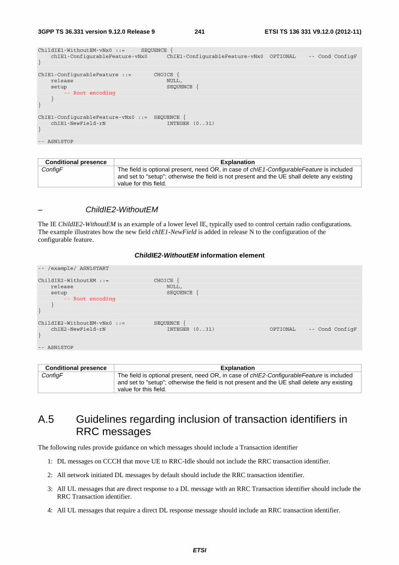
ETSI
ETSI TS 136 331 V9.12.0 (2012-11)2413GPP TS 36.331 version 9.12.0 Release 9
ChildIE1-WithoutEM-vNx0 ::= SEQUENCE { chIE1-ConfigurableFeature-vNx0 ChIE1-ConfigurableFeature-vNx0 OPTIONAL -- Cond ConfigF } ChIE1-ConfigurableFeature ::= CHOICE { release NULL, setup SEQUENCE { -- Root encoding } } ChIE1-ConfigurableFeature-vNx0 ::= SEQUENCE { chIE1-NewField-rN INTEGER (0..31) } -- ASN1STOP
Conditional presence Explanation ConfigF The field is optional present, need OR, in case of chIE1-ConfigurableFeature is included
and set to "setup"; otherwise the field is not present and the UE shall delete any existing value for this field.
– ChildIE2-WithoutEM
The IE ChildIE2-WithoutEM is an example of a lower level IE, typically used to control certain radio configurations. The example illustrates how the new field chIE1-NewField is added in release N to the configuration of the configurable feature.
ChildIE2-WithoutEM information element
-- /example/ ASN1START ChildIE2-WithoutEM ::= CHOICE { release NULL, setup SEQUENCE { -- Root encoding } } ChildIE2-WithoutEM-vNx0 ::= SEQUENCE { chIE2-NewField-rN INTEGER (0..31) OPTIONAL -- Cond ConfigF } -- ASN1STOP
Conditional presence Explanation ConfigF The field is optional present, need OR, in case of chIE2-ConfigurableFeature is included
and set to "setup"; otherwise the field is not present and the UE shall delete any existing value for this field.
A.5 Guidelines regarding inclusion of transaction identifiers in RRC messages
The following rules provide guidance on which messages should include a Transaction identifier
1: DL messages on CCCH that move UE to RRC-Idle should not include the RRC transaction identifier.
2: All network initiated DL messages by default should include the RRC transaction identifier.
3: All UL messages that are direct response to a DL message with an RRC Transaction identifier should include the RRC Transaction identifier.
4: All UL messages that require a direct DL response message should include an RRC transaction identifier.

ETSI
ETSI TS 136 331 V9.12.0 (2012-11)2423GPP TS 36.331 version 9.12.0 Release 9
5: All UL messages that are not in response to a DL message nor require a corresponding response from the network should not include the RRC Transaction identifier.
A.6 Protection of RRC messages (informative) The following list provides information which messages can be sent (unprotected) prior to security activation and which messages can be sent unprotected after security activation.
P…Messages that can be sent (unprotected) prior to security activation
A - I…Messages that can be sent without integrity protection after security activation
A - C…Messages that can be sent unciphered after security activation
NA… Message can never be sent after security activation

ETSI
ETSI TS 136 331 V9.12.0 (2012-11)2433GPP TS 36.331 version 9.12.0 Release 9
Message P A-I A-C Comment CSFBParametersRequestCDMA2000
+ - -
CSFBParametersResponseCDMA2000
+ - -
CounterCheck - - - CounterCheckResponse - - - DLInformationTransfer + - - HandoverFromEUTRAPreparationRequest (CDMA2000)
- - -
MasterInformationBlock + + + MBSFNAreaConfiguration + + + MeasurementReport + - - Justification for case “P”: RAN2 agreed that
measurement configuration may be sent prior to security activation
MobilityFromEUTRACommand - - - Paging + + + ProximityIndication - - - RRCConnectionReconfiguration + - - The message shall not be sent unprotected
before security activation if it is used to perform handover or to establish SRB2 and DRBs
RRCConnectionReconfigurationComplete
+ - - Unprotected, if sent as response to RRCConnectionReconfiguration which was sent before security activation
RRCConnectionReestablishment - + + This message is not protected by PDCP operation.
RRCConnectionReestablishmentComplete
- - -
RRCConnectionReestablishmentReject
- + + One reason to send this may be that the security context has been lost, therefore sent as unprotected.
RRCConnectionReestablishmentRequest
- - + This message is not protected by PDCP operation. However a short MAC-I is included.
RRCConnectionReject + NA NA RRCConnectionRelease + - - Justification for P: If the RRC connection
only for signalling not requiring DRBs or ciphered messages, or the signalling connection has to be released prematurely, this message is sent as unprotected.
RRCConnectionRequest + NA NA RRCConnectionSetup + NA NA RRCConnectionSetupComplete + NA NA SecurityModeCommand + NA NA Integrity protection applied, but no
ciphering (integrity verification done after the message received by RRC)
SecurityModeComplete - NA NA Integrity protection applied, but no ciphering. Ciphering is applied after completing the procedure.
SecurityModeFailure + NA NA Neither integrity protection nor ciphering applied.
SystemInformation + + + SystemInformationBlockType1 + + + UECapabilityEnquiry + - - UECapabilityInformation + - - UEInformationRequest - - - UEInformationResponse - - - ULHandoverPreparationTransfer (CDMA2000)
- - - This message should follow HandoverFromEUTRAPreparationRequest
ULInformationTransfer + - -

ETSI
ETSI TS 136 331 V9.12.0 (2012-11)2443GPP TS 36.331 version 9.12.0 Release 9
A.7 Miscellaneous The following miscellaneous conventions should be used:
- References: Whenever another specification is referenced, the specification number and optionally the relevant subclause, table or figure, should be indicated in addition to the pointer to the References section e.g. as follows: 'see TS 36.212 [22, 5.3.3.1.6]'.

ETSI
ETSI TS 136 331 V9.12.0 (2012-11)2453GPP TS 36.331 version 9.12.0 Release 9
Annex B (normative): Release 8 and 9 AS feature handling
B.1 Feature group indicators This annex contains the definitions of the bits in fields featureGroupIndicators (in Table B.1-1) and featureGroupIndRel9Add (in Table B.1-1a).
In this release of the protocol, the UE shall include the fields featureGroupIndicators in the IE UE-EUTRA-Capability. All the functionalities defined within the field featureGroupIndicators defined in Table B.1-1 or Table B.1-1a are mandatory for the UE, if the related capability (frequency band, RAT, SR-VCC or Inter-RAT ANR) is also supported. For a specific indicator, if all functionalities for a feature group listed in Table B.1-1 have been implemented and tested, the UE shall set the indicator as one (1), else (i.e. if any one of the functionalities in a feature group listed in Table B.1-1 or Table B.1-1a, which have not been implemented or tested), the UE shall set the indicator as zero (0).
The UE shall set all indicators that correspond to RATs not supported by the UE as zero (0).
The UE shall set all indicators, which do not have a definition in Table B.1-1 or Table B.1-1a, as zero (0).
If the optional fields featureGroupIndicators or featureGroupIndRel9Add are not included by a UE of a future release, the network may assume that all features pertaining to the RATs supported by the UE, respectively listed in Table B.1-1 or Table B.1-1a and deployed in the network, have been implemented and tested by the UE.
In Table B.1-1, a 'VoLTE capable UE' corresponds to a UE which is IMS voice capable
The indexing in Table B.1-1a starts from index 33, which is the leftmost bit in the field featureGroupIndRel9Add.
Table B.1-1: Definitions of feature group indicators
Index of indicator
(bit number)
Definition (description of the supported
functionality, if indicator set to one)
Notes If indicated "Yes" the feature shall be
implemented and successfully tested for
this version of the specification
FDD/ TDD diff
1 (leftmost bit)
- Intra-subframe frequency hopping for PUSCH scheduled by UL grant - DCI format 3a (TPC commands for PUCCH and PUSCH with single bit power adjustments) - PDSCH transmission mode 5 - Aperiodic CQI/PMI/RI reporting on PUSCH: Mode 2-0 – UE selected subband CQI without PMI - Aperiodic CQI/PMI/RI reporting on PUSCH: Mode 2-2 – UE selected subband CQI with multiple PMI
Yes
2 - Simultaneous CQI and ACK/NACK on PUCCH, i.e. PUCCH format 2a and 2b - Absolute TPC command for PUSCH - Resource allocation type 1 for PDSCH - Periodic CQI/PMI/RI reporting on PUCCH: Mode 2-0 – UE selected subband CQI without PMI - Periodic CQI/PMI/RI reporting on PUCCH: Mode 2-1 – UE selected subband CQI with single PMI
Yes
3 - 5bit RLC UM SN - 7bit PDCP SN
- can only be set to 1 if the UE has set bit number 7 to 1.
Yes, if UE supports VoLTE
No
4 - Short DRX cycle - can only be set to 1 if the UE has set bit
Yes

ETSI
ETSI TS 136 331 V9.12.0 (2012-11)2463GPP TS 36.331 version 9.12.0 Release 9
number 5 to 1.

ETSI
ETSI TS 136 331 V9.12.0 (2012-11)2473GPP TS 36.331 version 9.12.0 Release 9
5 - Long DRX cycle - DRX command MAC control element
Yes No
6 - Prioritised bit rate Yes No 7 - RLC UM - can only be set to 0
if the UE does not support VoLTE
Yes, if UE supports VoLTE
No
8 - EUTRA RRC_CONNECTED to UTRA FDD or UTRA TDD CELL_DCH PS handover, if the UE supports either only UTRAN FDD or only UTRAN TDD - EUTRA RRC_CONNECTED to UTRA FDD CELL_DCH PS handover, if the UE supports both UTRAN FDD and UTRAN TDD
- can only be set to 1 if the UE has set bit number 22 to 1
Yes for FDD, if UE supports UTRA FDD
Yes
9 - EUTRA RRC_CONNECTED to GERAN GSM_Dedicated handover
- related to SR-VCC - can only be set to 1 if the UE has set bit number 23 to 1
Yes
10 - EUTRA RRC_CONNECTED to GERAN (Packet_) Idle by Cell Change Order - EUTRA RRC_CONNECTED to GERAN (Packet_) Idle by Cell Change Order with NACC (Network Assisted Cell Change)
Yes
11 - EUTRA RRC_CONNECTED to CDMA2000 1xRTT CS Active handover
- related to SR-VCC - can only be set to 1 if the UE has sets bit number 24 to 1
Yes
12 - EUTRA RRC_CONNECTED to CDMA2000 HRPD Active handover
- can only be set to 1 if the UE has set bit number 26 to 1
Yes
13 - Inter-frequency handover (within FDD or TDD)
- can only be set to 1 if the UE has set bit number 25 to 1
Yes, unless UE only supports band 13
No
14 - Measurement reporting event: Event A4 – Neighbour > threshold - Measurement reporting event: Event A5 – Serving < threshold1 & Neighbour > threshold2
No
15 - Measurement reporting event: Event B1 – Neighbour > threshold for UTRAN FDD or UTRAN TDD, if the UE supports either only UTRAN FDD or only UTRAN TDD and has set bit number 22 to 1 - Measurement reporting event: Event B1 – Neighbour > threshold for UTRAN FDD or UTRAN TDD, if the UE supports both UTRAN FDD and UTRAN TDD and has set bit number 22 or 39 to 1, respectively - Measurement reporting event: Event B1 – Neighbour > threshold for GERAN, 1xRTT or HRPD, if the UE has set bit number 23, 24 or 26 to 1, respectively
- can only be set to 1 if the UE has set at least one of the bit number 22, 23, 24, 26 or 39 to 1.
Yes
16 - Intra-frequency periodical measurement reporting where triggerType is set to periodical and purpose is set to reportStrongestCells; - Inter-frequency periodical measurement reporting where triggerType is set to periodical and purpose is set to reportStrongestCells, if the UE has set bit number 25 to 1 - Inter-RAT periodical measurement reporting where triggerType is set to periodical and purpose is set to reportStrongestCells for UTRAN FDD or
Yes No

ETSI
ETSI TS 136 331 V9.12.0 (2012-11)2483GPP TS 36.331 version 9.12.0 Release 9
UTRAN TDD, if the UE supports either only UTRAN FDD or only UTRAN TDD and has set bit number 22 to 1 - Inter-RAT periodical measurement reporting where triggerType is set to periodical and purpose is set to reportStrongestCells for UTRAN FDD or UTRAN TDD, if the UE supports both UTRAN FDD and UTRAN TDD and has set bit number 22 or 39 to 1, respectively - Inter-RAT periodical measurement reporting where triggerType is set to periodical and purpose is set to reportStrongestCells for GERAN, 1xRTT or HRPD, if the UE has set bit number 23, 24 or 26 to 1, respectively NOTE: Event triggered periodical reporting (i.e. with triggerType set to event and with reportAmount > 1) is a mandatory functionality of event triggered reporting and therefore not the subject of this bit.
17 Intra-frequency ANR features including: - Intra-frequency periodical measurement reporting where triggerType is set to periodical and purpose is set to reportStrongestCells - Intra-frequency periodical measurement reporting where triggerType is set to periodical and purpose is set to reportCGI
- can only be set to 1 if the UE has set bit number 5 to 1.
Yes No
18 Inter-frequency ANR features including: - Inter-frequency periodical measurement reporting where triggerType is set to periodical and purpose is set to reportStrongestCells - Inter-frequency periodical measurement reporting where triggerType is set to periodical and purpose is set to reportCGI
- can only be set to 1 if the UE has set bit number 5 and bit number 25 to 1.
Yes, unless UE only supports band 13
No
19 Inter-RAT ANR features including: - Inter-RAT periodical measurement reporting where triggerType is set to periodical and purpose is set to reportStrongestCells for GERAN, if the UE has set bit number 23 to 1 - Inter-RAT periodical measurement reporting where triggerType is set to periodical and purpose is set to reportStrongestCellsForSON for UTRAN FDD or UTRAN TDD, if the UE supports either only UTRAN FDD or only UTRAN TDD and has set bit number 22 to 1 - Inter-RAT periodical measurement reporting where triggerType is set to periodical and purpose is set to reportStrongestCellsForSON for UTRAN FDD or UTRAN TDD, if the UE supports both UTRAN FDD and UTRAN TDD and has set bit number 22 or 39 to 1, respectively - Inter-RAT periodical measurement reporting where triggerType is set to periodical and purpose is set to reportStrongestCellsForSON for 1xRTT or HRPD, if the UE has set bit number 24 or 26 to 1, respectively
- can only be set to 1 if the UE has set bit number 5 to 1 and the UE has set at least one of the bit number 22, 39, 23, 24 or 26 to 1. - even if the UE sets bits 33 to 37, it shall still set bit 19 to 1 if inter-RAT ANR features are tested for all RATs for which inter-RAT measurement reporting is indicated as tested
Yes
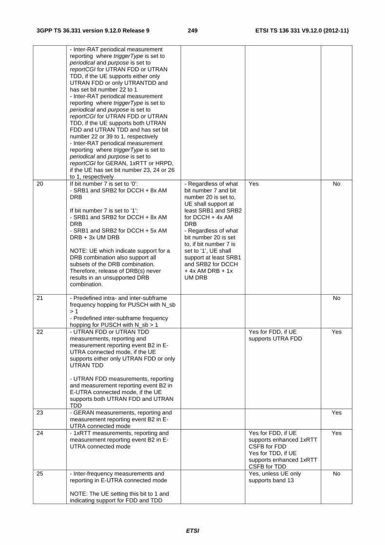
ETSI
ETSI TS 136 331 V9.12.0 (2012-11)2493GPP TS 36.331 version 9.12.0 Release 9
- Inter-RAT periodical measurement reporting where triggerType is set to periodical and purpose is set to reportCGI for UTRAN FDD or UTRAN TDD, if the UE supports either only UTRAN FDD or only UTRANTDD and has set bit number 22 to 1 - Inter-RAT periodical measurement reporting where triggerType is set to periodical and purpose is set to reportCGI for UTRAN FDD or UTRAN TDD, if the UE supports both UTRAN FDD and UTRAN TDD and has set bit number 22 or 39 to 1, respectively - Inter-RAT periodical measurement reporting where triggerType is set to periodical and purpose is set to reportCGI for GERAN, 1xRTT or HRPD, if the UE has set bit number 23, 24 or 26 to 1, respectively
20 If bit number 7 is set to ‘0’: - SRB1 and SRB2 for DCCH + 8x AM DRB If bit number 7 is set to ‘1’: - SRB1 and SRB2 for DCCH + 8x AM DRB - SRB1 and SRB2 for DCCH + 5x AM DRB + 3x UM DRB NOTE: UE which indicate support for a DRB combination also support all subsets of the DRB combination. Therefore, release of DRB(s) never results in an unsupported DRB combination.
- Regardless of what bit number 7 and bit number 20 is set to, UE shall support at least SRB1 and SRB2 for DCCH + 4x AM DRB - Regardless of what bit number 20 is set to, if bit number 7 is set to ‘1’, UE shall support at least SRB1 and SRB2 for DCCH + 4x AM DRB + 1x UM DRB
Yes No
21 - Predefined intra- and inter-subframe frequency hopping for PUSCH with N_sb > 1 - Predefined inter-subframe frequency hopping for PUSCH with N_sb > 1
No
22 - UTRAN FDD or UTRAN TDD measurements, reporting and measurement reporting event B2 in E-UTRA connected mode, if the UE supports either only UTRAN FDD or only UTRAN TDD - UTRAN FDD measurements, reporting and measurement reporting event B2 in E-UTRA connected mode, if the UE supports both UTRAN FDD and UTRAN TDD
Yes for FDD, if UE supports UTRA FDD
Yes
23 - GERAN measurements, reporting and measurement reporting event B2 in E-UTRA connected mode
Yes
24 - 1xRTT measurements, reporting and measurement reporting event B2 in E-UTRA connected mode
Yes for FDD, if UE supports enhanced 1xRTT CSFB for FDD Yes for TDD, if UE supports enhanced 1xRTT CSFB for TDD
Yes
25 - Inter-frequency measurements and reporting in E-UTRA connected mode NOTE: The UE setting this bit to 1 and indicating support for FDD and TDD
Yes, unless UE only supports band 13
No
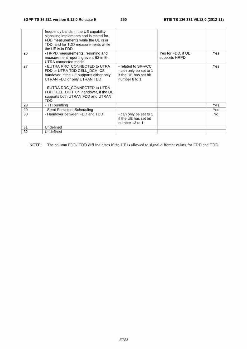
ETSI
ETSI TS 136 331 V9.12.0 (2012-11)2503GPP TS 36.331 version 9.12.0 Release 9
frequency bands in the UE capability signalling implements and is tested for FDD measurements while the UE is in TDD, and for TDD measurements while the UE is in FDD.
26 - HRPD measurements, reporting and measurement reporting event B2 in E-UTRA connected mode
Yes for FDD, if UE supports HRPD
Yes
27 - EUTRA RRC_CONNECTED to UTRA FDD or UTRA TDD CELL_DCH CS handover, if the UE supports either only UTRAN FDD or only UTRAN TDD - EUTRA RRC_CONNECTED to UTRA FDD CELL_DCH CS handover, if the UE supports both UTRAN FDD and UTRAN TDD
- related to SR-VCC - can only be set to 1 if the UE has set bit number 8 to 1
Yes
28 - TTI bundling Yes 29 - Semi-Persistent Scheduling Yes 30 - Handover between FDD and TDD - can only be set to 1
if the UE has set bit number 13 to 1
No
31 Undefined 32 Undefined
NOTE: The column FDD/ TDD diff indicates if the UE is allowed to signal different values for FDD and TDD.

ETSI
ETSI TS 136 331 V9.12.0 (2012-11)2513GPP TS 36.331 version 9.12.0 Release 9
Table B.1-1a: Definitions of feature group indicators
Index of indicator
(bit number)
Definition (description of the supported
functionality, if indicator set to one)
Notes If indicated "Yes" the feature shall be
implemented and successfully tested for
this version of the specification
FDD/ TDD diff
33 (leftmost bit)
Inter-RAT ANR features for UTRAN FDD including: - Inter-RAT periodical measurement reporting where triggerType is set to periodical and purpose is set to reportStrongestCellsForSON - Inter-RAT periodical measurement reporting where triggerType is set to periodical and purpose is set to reportCGI
- can only be set to 1 if the UE has set bit number 5 and bit number 22 to 1.
Yes
34 Inter-RAT ANR features for GERAN including: - Inter-RAT periodical measurement reporting where triggerType is set to periodical and purpose is set to reportStrongestCells - Inter-RAT periodical measurement reporting where triggerType is set to periodical and purpose is set to reportCGI
- can only be set to 1 if the UE has set bit number 5 and bit number 23 to 1.
Yes
35 Inter-RAT ANR features for 1xRTT including: - Inter-RAT periodical measurement reporting where triggerType is set to periodical and purpose is set to reportStrongestCellsForSON - Inter-RAT periodical measurement reporting where triggerType is set to periodical and purpose is set to reportCGI
- can only be set to 1 if the UE has set bit number 5 and bit number 24 to 1.
Yes
36 Inter-RAT ANR features for HRPD including: - Inter-RAT periodical measurement reporting where triggerType is set to periodical and purpose is set to reportStrongestCellsForSON - Inter-RAT periodical measurement reporting where triggerType is set to periodical and purpose is set to reportCGI
- can only be set to 1 if the UE has set bit number 5 and bit number 26 to 1.
Yes
37 Inter-RAT ANR features for UTRAN TDD including: - Inter-RAT periodical measurement reporting where triggerType is set to periodical and purpose is set to reportStrongestCellsForSON - Inter-RAT periodical measurement reporting where triggerType is set to periodical and purpose is set to reportCGI
- can only be set to 1 if the UE has set bit number 5 and bit number 39 to 1.
Yes
38 - EUTRA RRC_CONNECTED to UTRA TDD CELL_DCH PS handover, if the UE supports both UTRAN FDD and UTRAN TDD
- can only be set to 1 if the UE has set bit number 39 to 1.
Yes
39 - UTRAN TDD measurements, reporting and measurement reporting event B2 in E-UTRA connected mode, if the UE supports both UTRAN FDD and UTRAN TDD
Yes
40 - EUTRA RRC_CONNECTED to UTRA - related to SR-VCC Yes

ETSI
ETSI TS 136 331 V9.12.0 (2012-11)2523GPP TS 36.331 version 9.12.0 Release 9
TDD CELL_DCH CS handover, if the UE supports both UTRAN FDD and UTRAN TDD
- can only be set to 1 if the UE has set bit number 38 to 1.
41 Undefined 42 Undefined 43 Undefined 44 Undefined 45 Undefined 46 Undefined 47 Undefined 48 Undefined 49 Undefined 50 Undefined 51 Undefined 52 Undefined 53 Undefined 54 Undefined 55 Undefined 56 Undefined 57 Undefined 58 Undefined 59 Undefined 60 Undefined 61 Undefined 62 Undefined 63 Undefined 64 Undefined
NOTE: The column FDD/ TDD diff indicates if the UE is allowed to signal different values for FDD and TDD.
Clarification for mobility from EUTRAN and inter-frequency handover within EUTRAN
There are several feature groups related to mobility from E-UTRAN and inter-frequency handover within EUTRAN. The description of these features is based on the assumption that we have 5 main "functions" related to mobility from E-UTRAN:
A. Support of measurements and cell reselection procedure in idle mode
B. Support of RRC release with redirection procedure in connected mode
C. Support of Network Assisted Cell Change in connected mode
D. Support of measurements and reporting in connected mode
E. Support of handover procedure in connected mode
All functions can be applied for mobility to Inter-frequency to EUTRAN, GERAN, UTRAN, CDMA2000 HRPD and CDMA2000 1xRTT except for function C) which is only applicable for mobility to GERAN. Table B.1-2 below summarises the mobility functions that are supported based on the UE capability signaling (band support) and the setting of the feature group support indicators.
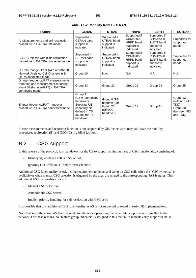
ETSI
ETSI TS 136 331 V9.12.0 (2012-11)2533GPP TS 36.331 version 9.12.0 Release 9
Table B.1-2: Mobility from E-UTRAN
Feature GERAN UTRAN HRPD 1xRTT EUTRAN
A. Measurements and cell reselection procedure in E-UTRA idle mode
Supported if GERAN band support is indicated
Supported if UTRAN band support is indicated
Supported if CDMA2000 HRPD band support is indicated
Supported if CDMA2000 1xRTT band support is indicated
Supported for supported bands
B. RRC release with blind redirection procedure in E-UTRA connected mode
Supported if GERAN band support is indicated
Supported if UTRAN band support is indicated
Supported if CDMA2000 HRPD band support is indicated
Supported if CDMA2000 1xRTT band support is indicated
Supported for supported bands
C. Cell Change Order (with or without) Network Assisted Cell Change) in E-UTRA connected mode
Group 10 N.A. N.A N.A N.A.
D. Inter-frequency/RAT measurements, reporting and measurement reporting event B2 (for inter-RAT) in E-UTRA connected mode
Group 23 Group 22 Group 26 Group 24 Group 25
E. Inter-frequency/RAT handover procedure in E-UTRA connected mode
Group 9 (GSM_connected handover) Separate UE capability bit defined in TS 36.306 for PS handover
Group 8 (PS handover) or Group 27 (SRVCC handover)
Group 12 Group 11
Group 13 (within FDD orTDD) Group 30 (between FDDand TDD)
In case measurements and reporting function is not supported by UE, the network may still issue the mobility procedures redirection (B) and CCO (C) in a blind fashion.
B.2 CSG support In this release of the protocol, it is mandatory for the UE to support a minimum set of CSG functionality consisting of:
- Identifying whether a cell is CSG or not;
- Ignoring CSG cells in cell selection/reselection.
Additional CSG functionality in AS, i.e. the requirement to detect and camp on CSG cells when the "CSG whitelist" is available or when manual CSG selection is triggered by the user, are related to the corresponding NAS features. This additional AS functionality consists of:
- Manual CSG selection;
- Autonomous CSG search;
- Implicit priority handling for cell reselection with CSG cells.
It is possible that this additional CSG functionality in AS is not supported or tested in early UE implementations.
Note that since the above AS features relate to idle mode operations, the capability support is not signalled to the network. For these reasons, no "feature group indicator" is assigned to this feature to indicate early support in Rel-8.

ETSI
ETSI TS 136 331 V9.12.0 (2012-11)2543GPP TS 36.331 version 9.12.0 Release 9
Annex C (informative): Change history

ETSI
ETSI TS 136 331 V9.12.0 (2012-11)2553GPP TS 36.331 version 9.12.0 Release 9
Change history Date TSG # TSG Doc. CR Rev Subject/Comment Old New 12/2007 RP-38 RP-070920 - Approved at TSG-RAN #38 and placed under Change Control 1.0.0 8.0.0 03/2008 RP-39 RP-080163 0001 4 CR to 36.331 with Miscellaneous corrections 8.0.0 8.1.0 03/2008 RP-39 RP-080164 0002 2 CR to 36.331 to convert RRC to agreed ASN.1 format 8.0.0 8.1.0 05/2008 RP-40 RP-080361 0003 1 CR to 36.331 on Miscellaneous clarifications/ corrections 8.1.0 8.2.0 09/2008 RP-41 RP-080693 0005 - CR on Miscellaneous corrections and clarifications 8.2.0 8.3.0 12/2008 RP-42 RP-081021 0006 - Miscellaneous corrections and clarifications 8.3.0 8.4.0 03/2009 RP-43 RP-090131 0007 - Correction to the Counter Check procedure 8.4.0 8.5.0 RP-43 RP-090131 0008 - CR to 36.331-UE Actions on Receiving SIB11 8.4.0 8.5.0 RP-43 RP-090131 0009 1 Spare usage on BCCH 8.4.0 8.5.0 RP-43 RP-090131 0010 - Issues in handling optional IE upon absence in GERAN NCL 8.4.0 8.5.0 RP-43 RP-090131 0011 - CR to 36.331 on Removal of useless RLC re-establishment at RB
release 8.4.0 8.5.0
RP-43 RP-090131 0012 1 Clarification to RRC level padding at PCCH and BCCH 8.4.0 8.5.0 RP-43 RP-090131 0013 - Removal of Inter-RAT message 8.4.0 8.5.0 RP-43 RP-090131 0014 - Padding of the SRB-ID for security input 8.4.0 8.5.0 RP-43 RP-090131 0015 - Validity of ETWS SIB 8.4.0 8.5.0 RP-43 RP-090131 0016 1 Configuration of the Two-Intervals-SPS 8.4.0 8.5.0 RP-43 RP-090131 0017 - Corrections on Scaling Factor Values of Qhyst 8.4.0 8.5.0 RP-43 RP-090131 0018 1 Optionality of srsMaxUppts 8.4.0 8.5.0 RP-43 RP-090131 0019 - CR for discussion on field name for common and dedicated IE 8.4.0 8.5.0 RP-43 RP-090131 0020 - Corrections to Connected mode mobility 8.4.0 8.5.0 RP-43 RP-090131 0021 - Clarification regarding the measurement reporting procedure 8.4.0 8.5.0 RP-43 RP-090131 0022 1 Corrections on s-Measure 8.4.0 8.5.0 RP-43 RP-090131 0023 1 R1 of CR0023 (R2-091029) on combination of SPS and TTI
bundling for TDD 8.4.0 8.5.0
RP-43 RP-090131 0024 - L3 filtering for path loss measurements 8.4.0 8.5.0 RP-43 RP-090131 0025 1 S-measure handling for reportCGI 8.4.0 8.5.0 RP-43 RP-090131 0026 1 Measurement configuration clean up 8.4.0 8.5.0 RP-43 RP-090131 0027 - Alignment of measurement quantities for UTRA 8.4.0 8.5.0 RP-43 RP-090131 0028 - CR to 36.331 on L1 parameters ranges alignment 8.4.0 8.5.0 RP-43 RP-090131 0029 - Default configuration for transmissionMode 8.4.0 8.5.0 RP-43 RP-090131 0030 - CR to 36.331 on RRC Parameters for MAC, RLC and PDCP 8.4.0 8.5.0 RP-43 RP-090131 0031 1 CR to 36.331 - Clarification on Configured PRACH Freq Offset 8.4.0 8.5.0 RP-43 RP-090131 0032 - Clarification on TTI bundling configuration 8.4.0 8.5.0 RP-43 RP-090131 0033 1 Update of R2-091039 on Inter-RAT UE Capability 8.4.0 8.5.0 RP-43 RP-090133 0034 - Feature Group Support Indicators 8.4.0 8.5.0 RP-43 RP-090131 0036 - Corrections to RLF detection 8.4.0 8.5.0 RP-43 RP-090131 0037 - Indication of Dedicated Priority 8.4.0 8.5.0 RP-43 RP-090131 0038 2 Security Clean up 8.4.0 8.5.0 RP-43 RP-090131 0039 - Correction of TTT value range 8.4.0 8.5.0 RP-43 RP-090131 0040 - Correction on CDMA measurement result IE 8.4.0 8.5.0 RP-43 RP-090131 0041 1 Clarification of Measurement Reporting 8.4.0 8.5.0 RP-43 RP-090131 0042 - Spare values in DL and UL Bandwidth in MIB and SIB2 8.4.0 8.5.0 RP-43 RP-090131 0044 1 Clarifications to System Information Block Type 8 8.4.0 8.5.0 RP-43 RP-090131 0045 - Reception of ETWS secondary notification 8.4.0 8.5.0 RP-43 RP-090131 0046 1 Validity time for ETWS message Id and Sequence No 8.4.0 8.5.0 RP-43 RP-090131 0047 - CR for Timers and constants values used during handover to E-
UTRA 8.4.0 8.5.0
RP-43 RP-090131 0048 - Inter-RAT Security Clarification 8.4.0 8.5.0 RP-43 RP-090131 0049 - CR to 36.331 on consistent naming of 1xRTT identifiers 8.4.0 8.5.0 RP-43 RP-090131 0050 - Capturing RRC behavior regarding NAS local release 8.4.0 8.5.0 RP-43 RP-090131 0051 - Report CGI before T321 expiry and UE null reporting 8.4.0 8.5.0 RP-43 RP-090131 0052 - System Information and 3 hour validity 8.4.0 8.5.0 RP-43 RP-090131 0053 1 Inter-Node AS Signalling 8.4.0 8.5.0 RP-43 RP-090131 0054 - Set of values for the parameter "messagePowerOffsetGroupB" 8.4.0 8.5.0 RP-43 RP-090131 0055 - CR to paging reception for ETWS capable UEs in
RRC_CONNECTED 8.4.0 8.5.0
RP-43 RP-090131 0056 1 CR for CSG related items in 36.331 8.4.0 8.5.0 RP-43 RP-090131 0057 1 SRS common configuration 8.4.0 8.5.0 RP-43 RP-090131 0058 - RRC processing delay 8.4.0 8.5.0 RP-43 RP-090131 0059 - CR for HNB Name 8.4.0 8.5.0 RP-43 RP-090131 0060 3 Handover to EUTRA delta configuration 8.4.0 8.5.0 RP-43 RP-090131 0063 - Delivery of Message Identifier and Serial Number to upper layers
for ETWS 8.4.0 8.5.0
RP-43 RP-090131 0066 - Clarification on the maximum size of cell lists 8.4.0 8.5.0 RP-43 RP-090131 0067 - Missing RRC messages in 'Protection of RRC messages' 8.4.0 8.5.0 RP-43 RP-090131 0069 1 Clarification on NAS Security Container 8.4.0 8.5.0 RP-43 RP-090131 0071 - Extension of range of CQI/PMI configuration index 8.4.0 8.5.0 RP-43 RP-090131 0072 1 Access barring alleviation in RRC connection establishment 8.4.0 8.5.0 RP-43 RP-090367 0077 6 Corrections to feature group support indicators 8.4.0 8.5.0 RP-43 RP-090131 0078 - CR from email discussion to capture DRX and TTT handling 8.4.0 8.5.0

ETSI
ETSI TS 136 331 V9.12.0 (2012-11)2563GPP TS 36.331 version 9.12.0 Release 9
RP-43 RP-090131 0079 1 Need Code handling on BCCH messages 8.4.0 8.5.0 RP-43 RP-090131 0080 - Unification of T300 and T301 and removal of miscallaneous FFSs 8.4.0 8.5.0 RP-43 RP-090131 0084 1 Proposed CR modifying the code-point definitions of
neighbourCellConfiguration 8.4.0 8.5.0
RP-43 RP-090131 0087 2 Remove Redundant Optionality in SIB8 8.4.0 8.5.0 RP-43 RP-090131 0089 - Corrections to the generic error handling 8.4.0 8.5.0 RP-43 RP-090131 0090 - Configurability of T301 8.4.0 8.5.0 RP-43 RP-090131 0091 1 Correction related to TTT 8.4.0 8.5.0 RP-43 RP-090131 0095 - CR for 36.331 on SPS-config 8.4.0 8.5.0 RP-43 RP-090131 0096 2 CR for Deactivation of periodical measurement 8.4.0 8.5.0 RP-43 RP-090131 0099 2 SMC and reconfiguration 8.4.0 8.5.0 RP-43 RP-090131 0101 - TDD handover 8.4.0 8.5.0 RP-43 RP-090131 0102 - Corrections to system information acquisition 8.4.0 8.5.0 RP-43 RP-090131 0106 - Some Corrections and Clarifications to 36.331 8.4.0 8.5.0 RP-43 RP-090131 0109 - Clarification on the Maximum number of ROHC context sessions
parameter 8.4.0 8.5.0
RP-43 RP-090131 0110 - Transmission of rrm-Config at Inter-RAT Handover 8.4.0 8.5.0 RP-43 RP-090131 0111 1 Use of SameRefSignalsInNeighbor parameter 8.4.0 8.5.0 RP-43 RP-090131 0112 - Default serving cell offset for measurement event A3 8.4.0 8.5.0 RP-43 RP-090131 0114 - dl-EARFCN missing in HandoverPreparationInformation 8.4.0 8.5.0 RP-43 RP-090131 0115 - Cleanup of references to 36.101 8.4.0 8.5.0 RP-43 RP-090131 0117 - Correction to the value range of UE-Categories 8.4.0 8.5.0 RP-43 RP-090131 0122 1 Correction on RRC connection re-establishment 8.4.0 8.5.0 RP-43 RP-090131 0124 - Performing Measurements to report CGI for CDMA2000 8.4.0 8.5.0 RP-43 RP-090131 0125 - CDMA2000-SystemTimeInfo in VarMeasurementConfiguration 8.4.0 8.5.0 RP-43 RP-090131 0126 - UE Capability Information for CDMA2000 1xRTT 8.4.0 8.5.0 RP-43 RP-090131 0127 - CDMA2000 related editorial changes 8.4.0 8.5.0 RP-43 RP-090131 0128 - Draft CR to 36.331 on State mismatch recovery at re-establishment 8.4.0 8.5.0 RP-43 RP-090131 0129 1 Draft CR to 36.331 on Renaming of AC barring related IEs 8.4.0 8.5.0 RP-43 RP-090131 0130 2 Draft CR to 36.331 on Inheriting of dedicated priorities at inter-RAT
reselection 8.4.0 8.5.0
RP-43 RP-090131 0135 - Proposed CR to 36.331 Description alignment for paging parameter, nB
8.4.0 8.5.0
RP-43 RP-090131 0139 2 Miscellaneous corrections and clarifications resulting from ASN.1 review
8.4.0 8.5.0
RP-43 RP-090131 0141 1 Correction regarding Redirection Information fo GERAN 8.4.0 8.5.0 RP-43 RP-090131 0142 - Further ASN.1 review related issues 8.4.0 8.5.0 RP-43 RP-090131 0143 - Periodic measurements 8.4.0 8.5.0 RP-43 RP-090131 0144 1 Further analysis on code point "OFF" for ri-ConfigIndex 8.4.0 8.5.0 RP-43 RP-090131 0145 1 Adding and deleting same measurement or configuration in one
message 8.4.0 8.5.0
RP-43 RP-090131 0147 - Corrections to IE dataCodingScheme in SIB11 8.4.0 8.5.0 RP-43 RP-090131 0148 - Clarification on Mobility from E-UTRA 8.4.0 8.5.0 RP-43 RP-090131 0149 - 36.331 CR related to “not applicable” 8.4.0 8.5.0 RP-43 RP-090131 0150 1 UE radio capability transfer 8.4.0 8.5.0 RP-43 RP-090131 0151 - CR to 36.331 on value of CDMA band classes 8.4.0 8.5.0 RP-43 RP-090131 0152 - Corrections to DRB modification 8.4.0 8.5.0 RP-43 RP-090131 0153 - Correction to presence condition for pdcp-config 8.4.0 8.5.0 RP-43 RP-090131 0155 - TDD HARQ-ACK feedback mode 8.4.0 8.5.0 RP-43 RP-090275 0157 - Corrections regarding use of carrierFreq for CDMA (SIB8) and
GERAN (measObject) 8.4.0 8.5.0
RP-43 RP-090321 0156 1 Sending of GERAN SI/PSI information at Inter-RAT Handover 8.4.0 8.5.0 RP-43 RP-090339 0158 - Clarification of CSG support 8.4.0 8.5.0 06/2009 RP-44 RP-090516 0159 - Octet alignment of VarShortMAC-Input 8.5.0 8.6.0 RP-44 RP-090516 0160 3 Minor corrections to the feature grouping 8.5.0 8.6.0 RP-44 RP-090516 0161 - Security clarification 8.5.0 8.6.0 RP-44 RP-090516 0162 1 Sending of GERAN SI/PSI information at Inter-RAT Handover 8.5.0 8.6.0 RP-44 RP-090516 0163 1 Correction of UE measurement model 8.5.0 8.6.0 RP-44 RP-090516 0164 - Restricting the reconfiguration of UM RLC SN field size 8.5.0 8.6.0 RP-44 RP-090516 0165 1 36.331 CR on Clarification on cell change order from GERAN to E-
UTRAN 8.5.0 8.6.0
RP-44 RP-090516 0166 - 36.331 CR - Handling of expired TAT and failed D-SR 8.5.0 8.6.0 RP-44 RP-090516 0167 1 Proposed CR to 36.331 Clarification on mandatory information in
AS-Config 8.5.0 8.6.0
RP-44 RP-090516 0168 2 Miscellaneous small corrections 8.5.0 8.6.0 RP-44 RP-090516 0173 - Clarification on the basis of delta signalling 8.5.0 8.6.0 RP-44 RP-090516 0177 - CR on Alignment of CCCH and DCCH handling of missing
mandatory field 8.5.0 8.6.0
RP-44 RP-090516 0180 2 Handling of Measurement Context During HO Preparation 8.5.0 8.6.0 RP-44 RP-090516 0181 - Clarification of key-eNodeB-Star in AdditionalReestabInfo 8.5.0 8.6.0 RP-44 RP-090516 0182 1 UE Capability Transfer 8.5.0 8.6.0 RP-44 RP-090516 0186 1 Clarification regarding mobility from E-UTRA in-between SMC and
SRB2/DRB setup 8.5.0 8.6.0
RP-44 RP-090516 0188 1 Correction and completion of specification conventions 8.5.0 8.6.0
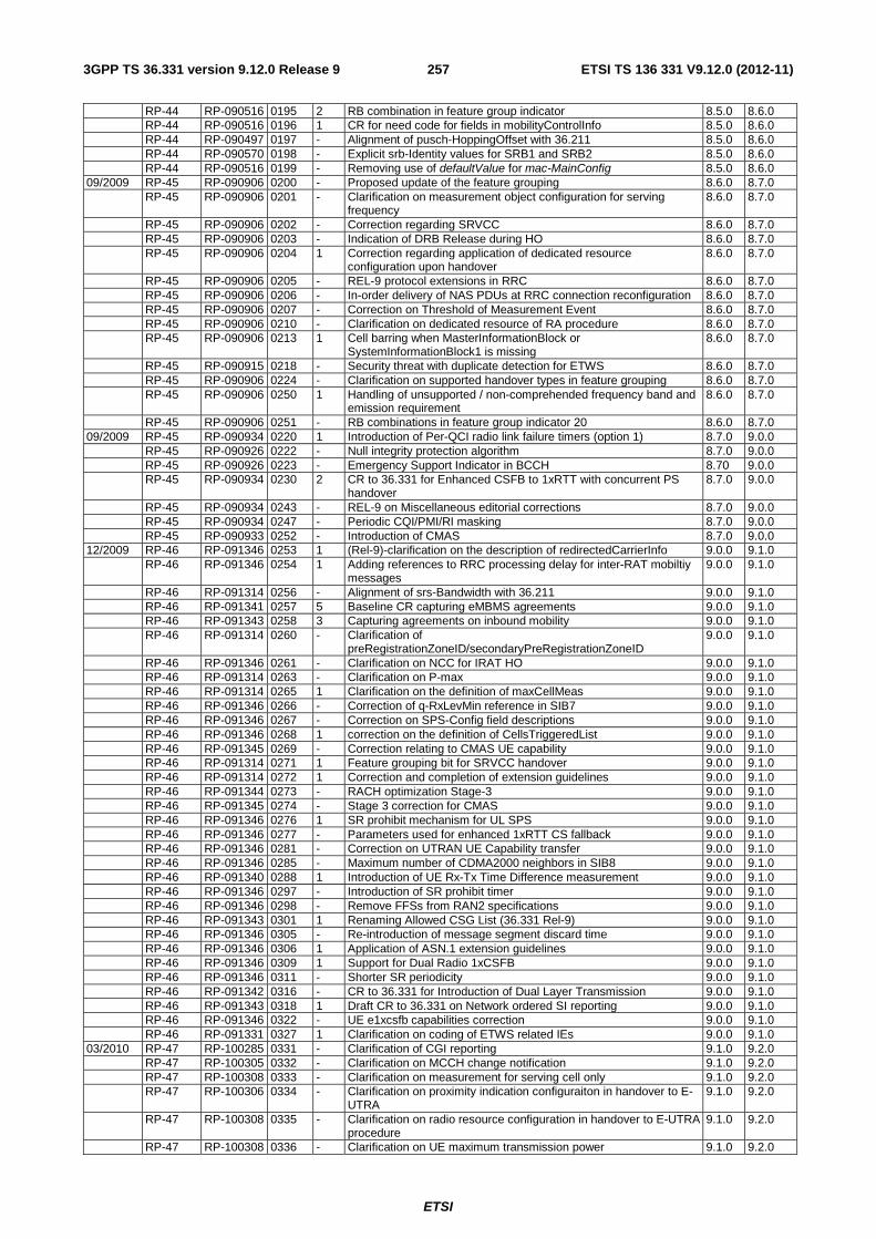
ETSI
ETSI TS 136 331 V9.12.0 (2012-11)2573GPP TS 36.331 version 9.12.0 Release 9
RP-44 RP-090516 0195 2 RB combination in feature group indicator 8.5.0 8.6.0 RP-44 RP-090516 0196 1 CR for need code for fields in mobilityControlInfo 8.5.0 8.6.0 RP-44 RP-090497 0197 - Alignment of pusch-HoppingOffset with 36.211 8.5.0 8.6.0 RP-44 RP-090570 0198 - Explicit srb-Identity values for SRB1 and SRB2 8.5.0 8.6.0 RP-44 RP-090516 0199 - Removing use of defaultValue for mac-MainConfig 8.5.0 8.6.0 09/2009 RP-45 RP-090906 0200 - Proposed update of the feature grouping 8.6.0 8.7.0 RP-45 RP-090906 0201 - Clarification on measurement object configuration for serving
frequency 8.6.0 8.7.0
RP-45 RP-090906 0202 - Correction regarding SRVCC 8.6.0 8.7.0 RP-45 RP-090906 0203 - Indication of DRB Release during HO 8.6.0 8.7.0 RP-45 RP-090906 0204 1 Correction regarding application of dedicated resource
configuration upon handover 8.6.0 8.7.0
RP-45 RP-090906 0205 - REL-9 protocol extensions in RRC 8.6.0 8.7.0 RP-45 RP-090906 0206 - In-order delivery of NAS PDUs at RRC connection reconfiguration 8.6.0 8.7.0 RP-45 RP-090906 0207 - Correction on Threshold of Measurement Event 8.6.0 8.7.0 RP-45 RP-090906 0210 - Clarification on dedicated resource of RA procedure 8.6.0 8.7.0 RP-45 RP-090906 0213 1 Cell barring when MasterInformationBlock or
SystemInformationBlock1 is missing 8.6.0 8.7.0
RP-45 RP-090915 0218 - Security threat with duplicate detection for ETWS 8.6.0 8.7.0 RP-45 RP-090906 0224 - Clarification on supported handover types in feature grouping 8.6.0 8.7.0 RP-45 RP-090906 0250 1 Handling of unsupported / non-comprehended frequency band and
emission requirement 8.6.0 8.7.0
RP-45 RP-090906 0251 - RB combinations in feature group indicator 20 8.6.0 8.7.0 09/2009 RP-45 RP-090934 0220 1 Introduction of Per-QCI radio link failure timers (option 1) 8.7.0 9.0.0 RP-45 RP-090926 0222 - Null integrity protection algorithm 8.7.0 9.0.0 RP-45 RP-090926 0223 - Emergency Support Indicator in BCCH 8.70 9.0.0 RP-45 RP-090934 0230 2 CR to 36.331 for Enhanced CSFB to 1xRTT with concurrent PS
handover 8.7.0 9.0.0
RP-45 RP-090934 0243 - REL-9 on Miscellaneous editorial corrections 8.7.0 9.0.0 RP-45 RP-090934 0247 - Periodic CQI/PMI/RI masking 8.7.0 9.0.0 RP-45 RP-090933 0252 - Introduction of CMAS 8.7.0 9.0.0 12/2009 RP-46 RP-091346 0253 1 (Rel-9)-clarification on the description of redirectedCarrierInfo 9.0.0 9.1.0 RP-46 RP-091346 0254 1 Adding references to RRC processing delay for inter-RAT mobiltiy
messages 9.0.0 9.1.0
RP-46 RP-091314 0256 - Alignment of srs-Bandwidth with 36.211 9.0.0 9.1.0 RP-46 RP-091341 0257 5 Baseline CR capturing eMBMS agreements 9.0.0 9.1.0 RP-46 RP-091343 0258 3 Capturing agreements on inbound mobility 9.0.0 9.1.0 RP-46 RP-091314 0260 - Clarification of
preRegistrationZoneID/secondaryPreRegistrationZoneID 9.0.0 9.1.0
RP-46 RP-091346 0261 - Clarification on NCC for IRAT HO 9.0.0 9.1.0 RP-46 RP-091314 0263 - Clarification on P-max 9.0.0 9.1.0 RP-46 RP-091314 0265 1 Clarification on the definition of maxCellMeas 9.0.0 9.1.0 RP-46 RP-091346 0266 - Correction of q-RxLevMin reference in SIB7 9.0.0 9.1.0 RP-46 RP-091346 0267 - Correction on SPS-Config field descriptions 9.0.0 9.1.0 RP-46 RP-091346 0268 1 correction on the definition of CellsTriggeredList 9.0.0 9.1.0 RP-46 RP-091345 0269 - Correction relating to CMAS UE capability 9.0.0 9.1.0 RP-46 RP-091314 0271 1 Feature grouping bit for SRVCC handover 9.0.0 9.1.0 RP-46 RP-091314 0272 1 Correction and completion of extension guidelines 9.0.0 9.1.0 RP-46 RP-091344 0273 - RACH optimization Stage-3 9.0.0 9.1.0 RP-46 RP-091345 0274 - Stage 3 correction for CMAS 9.0.0 9.1.0 RP-46 RP-091346 0276 1 SR prohibit mechanism for UL SPS 9.0.0 9.1.0 RP-46 RP-091346 0277 - Parameters used for enhanced 1xRTT CS fallback 9.0.0 9.1.0 RP-46 RP-091346 0281 - Correction on UTRAN UE Capability transfer 9.0.0 9.1.0 RP-46 RP-091346 0285 - Maximum number of CDMA2000 neighbors in SIB8 9.0.0 9.1.0 RP-46 RP-091340 0288 1 Introduction of UE Rx-Tx Time Difference measurement 9.0.0 9.1.0 RP-46 RP-091346 0297 - Introduction of SR prohibit timer 9.0.0 9.1.0 RP-46 RP-091346 0298 - Remove FFSs from RAN2 specifications 9.0.0 9.1.0 RP-46 RP-091343 0301 1 Renaming Allowed CSG List (36.331 Rel-9) 9.0.0 9.1.0 RP-46 RP-091346 0305 - Re-introduction of message segment discard time 9.0.0 9.1.0 RP-46 RP-091346 0306 1 Application of ASN.1 extension guidelines 9.0.0 9.1.0 RP-46 RP-091346 0309 1 Support for Dual Radio 1xCSFB 9.0.0 9.1.0 RP-46 RP-091346 0311 - Shorter SR periodicity 9.0.0 9.1.0 RP-46 RP-091342 0316 - CR to 36.331 for Introduction of Dual Layer Transmission 9.0.0 9.1.0 RP-46 RP-091343 0318 1 Draft CR to 36.331 on Network ordered SI reporting 9.0.0 9.1.0 RP-46 RP-091346 0322 - UE e1xcsfb capabilities correction 9.0.0 9.1.0 RP-46 RP-091331 0327 1 Clarification on coding of ETWS related IEs 9.0.0 9.1.0 03/2010 RP-47 RP-100285 0331 - Clarification of CGI reporting 9.1.0 9.2.0 RP-47 RP-100305 0332 - Clarification on MCCH change notification 9.1.0 9.2.0 RP-47 RP-100308 0333 - Clarification on measurement for serving cell only 9.1.0 9.2.0 RP-47 RP-100306 0334 - Clarification on proximity indication configuraiton in handover to E-
UTRA 9.1.0 9.2.0
RP-47 RP-100308 0335 - Clarification on radio resource configuration in handover to E-UTRA procedure
9.1.0 9.2.0
RP-47 RP-100308 0336 - Clarification on UE maximum transmission power 9.1.0 9.2.0

ETSI
ETSI TS 136 331 V9.12.0 (2012-11)2583GPP TS 36.331 version 9.12.0 Release 9
RP-47 RP-100308 0337 - Correction to field descriptions of UE-EUTRA-Capability 9.1.0 9.2.0 RP-47 RP-100305 0338 - Correction to MBMS scheduling terminology 9.1.0 9.2.0 RP-47 RP-100308 0339 - Corrections to SIB8 9.1.0 9.2.0 RP-47 RP-100306 0340 - CR 36.331 R9 for Unifying SI reading for ANR and inbound mobility 9.1.0 9.2.0 RP-47 RP-100308 0341 1 CR to 36.331 for 1xRTT pre-registration information in SIB8 9.1.0 9.2.0 RP-47 RP-100305 0342 - CR to 36.331 on corrections for MBMS 9.1.0 9.2.0 RP-47 RP-100306 0343 1 CR to 36.331 on CSG identity reporting 9.1.0 9.2.0 RP-47 RP-100308 0344 2 CR to 36.331 on Optionality of Rel-9 UE features 9.1.0 9.2.0 RP-47 RP-100308 0345 1 CR to 36.331 on Service Specific Acces Control (SSAC) 9.1.0 9.2.0 RP-47 RP-100308 0346 - Introduction of power-limited device indication in UE capability. 9.1.0 9.2.0 RP-47 RP-100305 0347 - Missing agreement in MCCH change notification. 9.1.0 9.2.0 RP-47 RP-100305 0348 1 Corrections related to MCCH change notification and value ranges 9.1.0 9.2.0 RP-47 RP-100306 0349 2 Prohibit timer for proximity indication 9.1.0 9.2.0 RP-47 RP-100306 0350 1 Proximity Indication after handover and re-establishment 9.1.0 9.2.0 RP-47 RP-100305 0351 - Specifying the exact mapping of notificationIndicator in SIB13 to
PDCCH bits 9.1.0 9.2.0
RP-47 RP-100308 0352 - Corrections out of ASN.1 review scope 9.1.0 9.2.0 RP-47 RP-100308 0353 - CR on clarification of system information change 9.1.0 9.2.0 RP-47 RP-100285 0358 - Measurement Result CDMA2000 Cell 9.1.0 9.2.0 RP-47 RP-100304 0361 - Correction on the range of UE Rx-Tx time difference measurement
result 9.1.0 9.2.0
RP-47 RP-100305 0362 - Small clarifications regarding MBMS 9.1.0 9.2.0 RP-47 RP-100308 0363 - Introduction of REL-9 indication within field accessStratumRelease 9.1.0 9.2.0 RP-47 RP-100306 0364 - Extending mobility description to cover inbound mobility 9.1.0 9.2.0 RP-47 RP-100308 0365 1 Clarification regarding enhanced CSFB to 1XRTT 9.1.0 9.2.0 RP-47 RP-100308 0368 - Handling of dedicated RLF timers 9.1.0 9.2.0 RP-47 RP-100305 0370 1 Clarification on UE's behavior of receiving MBMS service 9.1.0 9.2.0 RP-47 RP-100305 0371 - MBMS Service ID and Session ID 9.1.0 9.2.0 RP-47 RP-100305 0372 1 Inclusion of non-MBSFN region length in SIB13 9.1.0 9.2.0 RP-47 RP-100309 0374 1 CR to 36.331 for e1xCSFB access class barring parameters in
SIB8 9.1.0 9.2.0
RP-47 RP-100308 0375 - Multiple 1xRTT/HRPD target cells in MobilityFromEUTRACommand
9.1.0 9.2.0
RP-47 RP-100308 0376 - Independent support indicators for Dual-Rx CSFB and S102 in SIB8
9.1.0 9.2.0
RP-47 RP-100285 0378 - Clarification on DRX StartOffset for TDD 9.1.0 9.2.0 RP-47 RP-100308 0379 1 Miscellaneous corrections from REL-9 ASN.1 review 9.1.0 9.2.0 RP-47 RP-100308 0381 - Need codes and missing conventions 9.1.0 9.2.0 RP-47 RP-100308 0383 1 Introduction of Full Configuration Handover for handling earlier eNB
releases 9.1.0 9.2.0
RP-47 RP-100308 0385 - Clarification to SFN reference in RRC 9.1.0 9.2.0 RP-47 RP-100308 0390 - RSRP and RSRQ based Thresholds 9.1.0 9.2.0 RP-47 RP-100189 0392 3 Redirection enhancements to GERAN 9.1.0 9.2.0 RP-47 RP-100308 0398 - Cell reselection enhancements CR for 36.331 9.1.0 9.2.0 RP-47 RP-100307 0401 3 CR on UE-originated RLFreporting for MRO SON use case 9.1.0 9.2.0 RP-47 RP-100309 0402 3 CR to 36.331 on Redirection enhancements to UTRAN 9.1.0 9.2.0 RP-47 RP-100306 0403 2 Proximity status indication handling at mobility 9.1.0 9.2.0 RP-47 RP-100305 0404 - Upper layer aspect of MBSFN area id 9.1.0 9.2.0 RP-47 RP-100308 0405 - Redirection for enhanced 1xRTT CS fallback with concurrent
PSHO 9.1.0 9.2.0
RP-47 RP-100301 0406 - Avoiding interleaving transmission of CMAS notifications 9.1.0 9.2.0 RP-47 RP-100308 0407 1 Introduction of UE GERAN DTM capability indicator 9.1.0 9.2.0 RP-47 RP-100381 0408 2 Introducing provisions for late ASN.1 corrections 9.1.0 9.2.0 RP-47 RP-100245 0411 - Correction/ alignment of REL-9 UE capability signalling 9.1.0 9.2.0 06/2010 RP-48 RP-100553 0412 - Clarification for mapping between warning message and CB-data 9.2.0 9.3.0 RP-48 RP-100556 0413 - Clarification of radio link failure related actions 9.2.0 9.3.0 RP-48 RP-100554 0414 - Clarification on UE actions upon leaving RRC_CONNECTED 9.2.0 9.3.0 RP-48 RP-100553 0415 - Correction on CMAS system information 9.2.0 9.3.0 RP-48 RP-100554 0416 1 Corrections to MBMS 9.2.0 9.3.0 RP-48 RP-100536 0418 - Decoding of unknown future extensions 9.2.0 9.3.0 RP-48 RP-100556 0419 1 Miscellaneous small corrections and clarifications 9.2.0 9.3.0 RP-48 RP-100551 0420 - Prohibit timer for proximity indication 9.2.0 9.3.0 RP-48 RP-100556 0421 - RLF report for MRO correction 9.2.0 9.3.0 RP-48 RP-100546 0423 1 Missing UTRA bands in IRAT-ParametersUTRA-FDD 9.2.0 9.3.0 RP-48 RP-100556 0424 - Correction on handling of dedicated RLF timers 9.2.0 9.3.0 RP-48 RP-100556 0431 1 Protection of RRC messages 9.2.0 9.3.0 RP-48 RP-100556 0433 - Handling missing Essential system information 9.2.0 9.3.0 RP-48 RP-100551 0434 1 Clarification on UMTS CSG detected cell reporting in LTE 9.2.0 9.3.0 RP-48 RP-100556 0436 - Introducing provisions for late corrections 9.2.0 9.3.0 RP-48 RP-100556 0437 - Clarification regarding / alignment of REL-9 UE capabilities 9.2.0 9.3.0 09/2010 RP-49 RP-100845 0440 - Correction to 3GPP2 reference for interworking with cdma2000 1x 9.3.0 9.4.0 RP-49 RP-100851 0441 - Clarification on UL handover preparation transfer 9.3.0 9.4.0 RP-49 RP-100851 0442 1 Clarifications regarding fullConfiguration 9.3.0 9.4.0

ETSI
ETSI TS 136 331 V9.12.0 (2012-11)2593GPP TS 36.331 version 9.12.0 Release 9
RP-49 RP-100851 0443 - Clarifications regarding handover to E-UTRAN 9.3.0 9.4.0 RP-49 RP-100854 0444 - Correction on the table of conditionally mandatory Release 9
features 9.3.0 9.4.0
RP-49 RP-100851 0445 - Corrections to TS36.331 on MeasConfig IE 9.3.0 9.4.0 RP-49 RP-100853 0446 2 CR to 36.331 on clarification for MBMS PTM RBs 9.3.0 9.4.0 RP-49 RP-100851 0447 - Introduction of late corrections container for E-UTRA UE
capabilities 9.3.0 9.4.0
RP-49 RP-100851 0448 - Renaming of containers for late non-critical extensions 9.3.0 9.4.0 RP-49 RP-100851 0452 - Clarifications Regarding Redirection from LTE 9.3.0 9.4.0 RP-49 RP-100845 0456 - Description of multi-user MIMO functionality in feature group
indicator table 9.3.0 9.4.0
RP-49 RP-100845 0458 - Correct the PEMAX_H to PEMAX 9.3.0 9.4.0 RP-49 RP-100851 0460 - Clarification for feature group indicator bit 11 9.3.0 9.4.0 RP-49 RP-100851 0465 1 Clarification of FGI setting for inter-RAT features not supported by
the UE 9.3.0 9.4.0
RP-49 RP-101008 0475 1 FGI settings in Rel-9 9.3.0 9.4.0 12/2010 RP-50 RP-101197 0483 - Clarification on Meaning of FGI Bits 9.4.0 9.5.0 RP-50 RP-101197 0485 - Clarification regarding reconfiguration of the quantityConfig 9.4.0 9.5.0 RP-50 RP-101210 0486 1 Corrections to the presence of IE regarding DRX and CQI 9.4.0 9.5.0 RP-50 RP-101210 0493 - The field descriptions of MeasObjectEUTRA 9.4.0 9.5.0 RP-50 RP-101197 0498 1 Clarification of FGI settings non ANR periodical measurement
reporting 9.4.0 9.5.0
RP-50 RP-101209 0500 - Corrections to RLF Report 9.4.0 9.5.0 RP-50 RP-101206 0519 1 T321 timer fix 9.4.0 9.5.0 RP-50 RP-101197 0524 - Restriction of AC barring parameter setting 9.4.0 9.5.0 RP-50 RP-101210 0525 - Removal of SEQUENCE OF SEQUENCE in
UEInformationResponse 9.4.0 9.5.0
RP-50 RP-101197 0526 1 Clarification regarding default configuration value N/A 9.4.0 9.5.0 RP-50 RP-101431 0532 - Splitting FGI bit 3 9.4.0 9.5.0 03/2011 RP-51 RP-110272 0552 - Presence condition for cellSelectionInfo-v920 in SIB1 9.5.0 9.6.0 RP-51 RP-110272 0578 - Correction to cs-fallbackIndicator field description 9.5.0 9.6.0 RP-51 RP-110265 0586 - Clarification of band indicator in handover from E-UTRAN to
GERAN 9.5.0 9.6.0
RP-51 RP-110272 0608 - Minor ASN.1 corrections for the UEInformationResponse message 9.5.0 9.6.0 RP-51 RP-110272 0639 - Small corrections to ETWS & CMAS system information 9.5.0 9.6.0 RP-51 RP-110455 0647 2 Updates to FGI settings 9.5.0 9.6.0 06/2011 RP-52 RP-110830 0652 - Add pre Rel-10 procedures to processing delay requirement for
RRC procedure Section 11.2 9.6.0 9.7.0
RP-52 RP-110830 0657 - Clarification of optionality of UE features without capability 9.6.0 9.7.0 RP-52 RP-110830 0668 - FGI bit for handover between LTE FDD/TDD 9.6.0 9.7.0 RP-52 RP-110828 0692 1 Correction for SR-VCC and QCI usage 9.6.0 9.7.0 RP-52 RP-110830 0699 - Radio frame alignment of CSA and MSP 9.6.0 9.7.0 RP-52 RP-110830 0748 - Default value of extensions introduced from REL-9 9.6.0 9.7.0 09/2011 RP-53 RP-111280 0756 - Correction to Subframe Allocation End in PMCH-Info 9.7.0 9.8.0 RP-53 RP-111278 0765 2 36.331 correction on CSG identity validity to allow introduction of
CSG RAN sharing 9.7.0 9.8.0
RP-53 RP-111280 0782 - Clarification on for which subframes signalling MCS applies 9.7.0 9.8.0 RP-53 RP-111272 0809 - GERAN SI format for cell change order&PS handover& enhanced
redirection to GERAN 9.7.0 9.8.0
12/2011 RP-54 RP-111706 0825 - Clarification on SPS intervals 9.8.0 9.9.0 RP-54 RP-111706 0834 - Clarification of the event B1 and ANR related FGI bits 9.8.0 9.9.0 RP-54 RP-111706 0843 - 36.331 CR SPS reconfiguration 9.8.0 9.9.0 RP-54 RP-111706 0844 - Clarification on parallel message transmission upon connection re-
establishment 9.8.0 9.9.0
03/2012 RP-55 RP-120321 0856 - CR to 36.331 on cdma2000 band classes and references 9.9.0 9.10.0 RP-55 RP-120355 0901 1 Introducing means to signal different FDD/TDD Capabilities/FGIs
for Dual-xDD UE 9.9.0 9.10.0
06/2012 RP-56 RP-120805 0908 - SPS Reconfiguration 9.10.0 9.11.0 RP-56 RP-120805 0911 1 Change in Scheduling Information for ETWS 9.10.0 9.11.0 RP-56 RP-120854 0913 1 Clarification of mch-SchedulingPeriod configuration 9.10.0 9.11.0 RP-56 RP-120808 0915 1 Change in Scheduling Information for CMAS 9.10.0 9.11.0 RP-56 RP-120808 0930 - T321 value for UTRA SI acquisition 9.10.0 9.11.0 RP-56 RP-120733 0977 - Introduction of multiple frequency band indicator 9.10.0 9.11.0 09/2012 RP-57 RP-121359 1006 - Voice support Capabilities 9.11.0 9.12.0 RP-57 RP-121361 1011 - Differentiating UTRAN modes in FGIs 9.11.0 9.12.0 RP-57 RP-121394 1039 - Rules for including featureGroupIndRel9Add in Rel-9 9.11.0 9.12.0

ETSI
ETSI TS 136 331 V9.12.0 (2012-11)2603GPP TS 36.331 version 9.12.0 Release 9
History
Document history
V9.0.0 October 2009 Publication
V9.1.0 February 2010 Publication
V9.2.0 April 2010 Publication
V9.3.0 July 2010 Publication
V9.4.0 October 2010 Publication
V9.5.0 January 2011 Publication
V9.6.0 March 2011 Publication
V9.7.0 July 2011 Publication
V9.8.0 November 2011 Publication
V9.9.0 January 2012 Publication
V9.10.0 March 2012 Publication
V9.11.0 July 2012 Publication
V9.12.0 November 2012 Publication