ether-mach mach3 plugin guideether-mach.com/static/manuals/ether-mach-mach3-manual-1...ether-mach :...
TRANSCRIPT
Ether-Mach : Ethernet Motion Controller Mach3 Guide : 1.0 9-12-2017
Ether-Mach Mach3 Plugin Guide
Ethernet Motion Controller for Artsoft's Mach3 CNC.
Features
• Connects over a dedicated 100 Mbps Ethernet connection.
• Smooth motion on 6 coordinated axes plus a spindle motor.
• Supports homing, jogging, probing, MPGs, THC and PWM/motor spindle control.
• 15 digital inputs (with configurable debounce) and 36 digital outputs on 3 IDC 26 (parallel port) headers.
• Fully configurable IO: No need to rewire when you can just reconfigure!
• 3.3v or 5v pin voltage. Runs on a 9-24 volt DC supply.
• On-the-fly firmware upgrades for forwards compatibility.
Product Brief
This guide covers the setup and usage of the Ether-Mach Motion Controller with Artsoft’s Mach3. Originally released for Mach4, we have back-ported support for our new motion controller to Mach3 at the request of many customers. With theEther-Mach controller and Mach3, you can build a CNC system that is faster, more configurable, and more responsive than ever before! With Ethernet connectivity and 3 parallel port headers, Ether-Mach is a simple, reliable, and performant solutionfor your next CNC project.
Ether-Mach Kit Contents
• The Ether-Mach breakout board, with Ethernet connectivity and 3 parallel ports.
• A 10 ft. CAT5 Ethernet cable.
• One IDC to DB25 female ribbon cable.
The kit may include installation media, but it typically ships with an installer and manual for Mach4. The Mach3 plugin and this guide can be downloaded at http://ether-mach.com.
© Stepper3 LLC 2017 Page 1 of 24
Ether-Mach : Ethernet Motion Controller Mach3 Guide : 1.0 9-12-2017
Table of Contents
Table of ContentsFeatures......................................................................................................................................................1
Product Brief..........................................................................................................................................1Ether-Mach Kit Contents............................................................................................................................1Table of Contents.......................................................................................................................................21: Setting Up Ether-Mach...........................................................................................................................3
1.1: Step 1: Powering up the Breakout Board.......................................................................................3...............................................................................................................................................................31.2: Step 2: Connecting your CNC System.............................................................................................31.3: Step 3: Install the Ether-Mach Plugin.............................................................................................31.4: Step 4: Configure your network settings and connect the board to the PC..................................4
1.4.1: Step 4, Part 1: Open Network Connections............................................................................41.4.2: Step 4, Part 2: Right click your Ethernet adapter and click properties...................................71.4.3: Step 4, Part 3: Disable every check box except for “Internet Protocol Version 4 (TCP/IPv4)”..........................................................................................................................................................71.4.4: Step 4, Part 4: With “Internet Protocol Version 4” enabled and selected, click properties:..81.4.5: Step 4, Part 5: Configure the dialog to look like the picture below........................................81.4.6: Step 4, Part 6: Close that dialog by pressing OK, then close the Ethernet Properties dialog by pressing OK..................................................................................................................................9
1.5: Step 5: Start Mach3 and select Ether-Mach-MACH3 as your motion device................................92: Mach3 Configuration...........................................................................................................................11
2.1: Changing settings.........................................................................................................................112.2: Ignored settings............................................................................................................................112.3: Motor Numbers............................................................................................................................12
3: Plugin Configuration.............................................................................................................................133.1: General Settings...........................................................................................................................133.2: Digital Outputs Configuration......................................................................................................153.3: Digital Inputs Configuration.........................................................................................................163.4: Board Configuration Parameters..................................................................................................173.5: Motor Settings..............................................................................................................................183.6: Plugin Configuration Parameters..................................................................................................19
4: Torch Height Control............................................................................................................................205: Breakout Board Information................................................................................................................21
5.1 Other Information.........................................................................................................................226. Updating Board Firmware....................................................................................................................237: Troubleshooting...................................................................................................................................23
© Stepper3 LLC 2017 Page 2 of 24
Ether-Mach : Ethernet Motion Controller Mach3 Guide : 1.0 9-12-2017
1: Setting Up Ether-Mach
This section will guide you through setting up the breakout board, adding the Ether-Mach plugin to Mach3, and getting Mach3 to connect to the breakout board. After this is complete, the next section will explain how to configure the plugin settings to set up correct IO mappings and behavior on your board.
1.1: Step 1: Powering up the Breakout Board
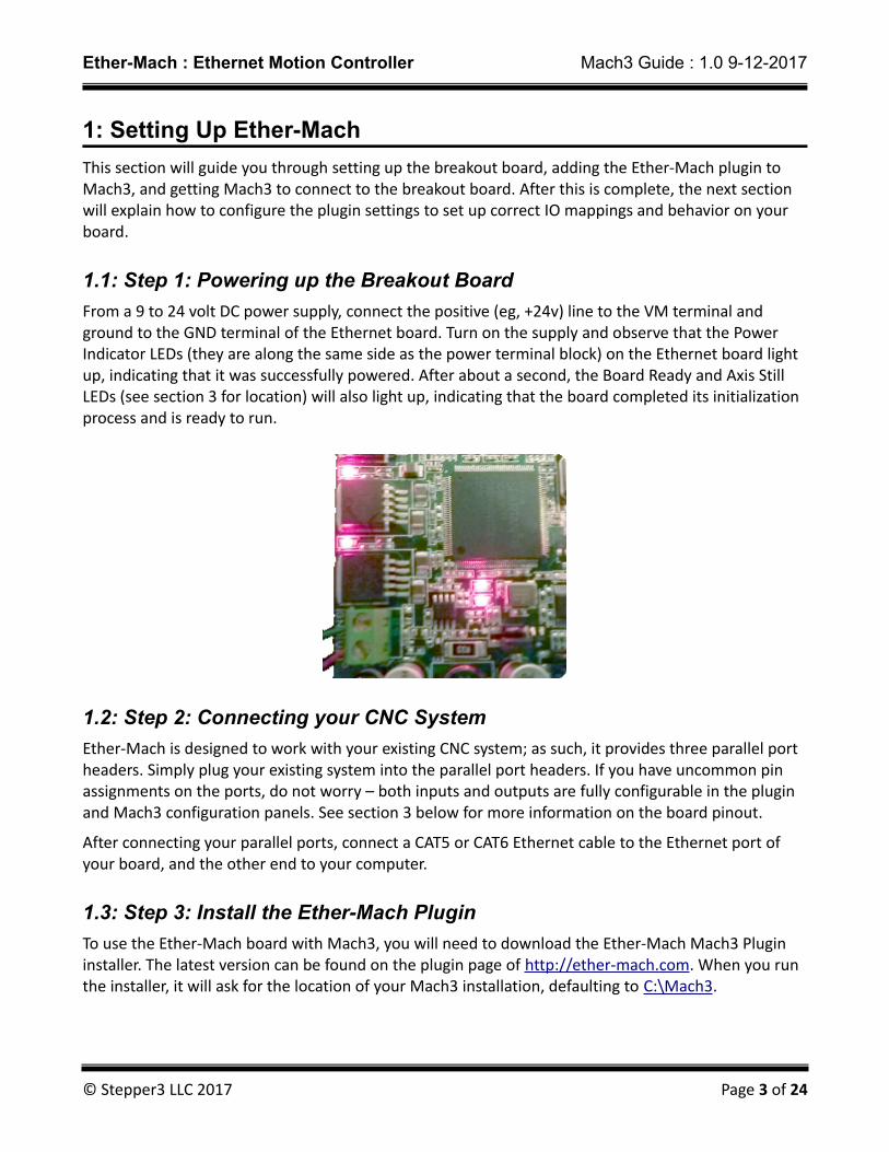
From a 9 to 24 volt DC power supply, connect the positive (eg, +24v) line to the VM terminal and ground to the GND terminal of the Ethernet board. Turn on the supply and observe that the Power Indicator LEDs (they are along the same side as the power terminal block) on the Ethernet board light up, indicating that it was successfully powered. After about a second, the Board Ready and Axis Still LEDs (see section 3 for location) will also light up, indicating that the board completed its initialization process and is ready to run.
1.2: Step 2: Connecting your CNC System
Ether-Mach is designed to work with your existing CNC system; as such, it provides three parallel port headers. Simply plug your existing system into the parallel port headers. If you have uncommon pin assignments on the ports, do not worry – both inputs and outputs are fully configurable in the plugin and Mach3 configuration panels. See section 3 below for more information on the board pinout.
After connecting your parallel ports, connect a CAT5 or CAT6 Ethernet cable to the Ethernet port of your board, and the other end to your computer.
1.3: Step 3: Install the Ether-Mach Plugin
To use the Ether-Mach board with Mach3, you will need to download the Ether-Mach Mach3 Plugin installer. The latest version can be found on the plugin page of http://ether-mach.com. When you run the installer, it will ask for the location of your Mach3 installation, defaulting to C:\Mach3.
© Stepper3 LLC 2017 Page 3 of 24
Ether-Mach : Ethernet Motion Controller Mach3 Guide : 1.0 9-12-2017
1.4: Step 4: Configure your network settings and connect the board to the PC
In order to function efficiently and avoid interference from other processes running on your system, you should follow the steps below to configure the Ethernet interface to disable all unnecessary services. If you do not do this, system services such as AutoIP or DHCP can interrupt or interfere with board connectivity, if you can connect at all. The instructions below include pictures for Windows 7, 8, and 10 (in steps where the process is the same, Windows 7 pictures are shown).
1.4.1: Step 4, Part 1: Open Network Connections
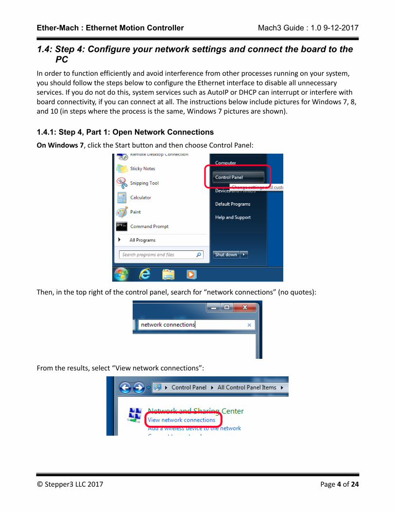
On Windows 7, click the Start button and then choose Control Panel:
Then, in the top right of the control panel, search for “network connections” (no quotes):
From the results, select “View network connections”:
© Stepper3 LLC 2017 Page 4 of 24
Ether-Mach : Ethernet Motion Controller Mach3 Guide : 1.0 9-12-2017
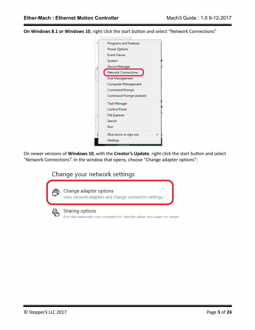
On Windows 8.1 or Windows 10, right click the start button and select “Network Connections”
On newer versions of Windows 10, with the Creator’s Update, right click the start button and select “Network Connections”. In the window that opens, choose “Change adapter options”:
© Stepper3 LLC 2017 Page 5 of 24

Ether-Mach : Ethernet Motion Controller Mach3 Guide : 1.0 9-12-2017
On regular Windows 8, press the windows key on your keyboard and then type “Network Connections” (no quotes). A search should begin on the right – choose the “View network connections” result:
© Stepper3 LLC 2017 Page 6 of 24
Ether-Mach : Ethernet Motion Controller Mach3 Guide : 1.0 9-12-2017
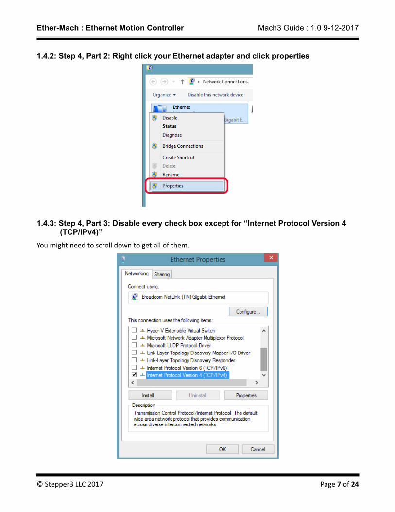
1.4.2: Step 4, Part 2: Right click your Ethernet adapter and click properties
1.4.3: Step 4, Part 3: Disable every check box except for “Internet Protocol Version 4 (TCP/IPv4)”
You might need to scroll down to get all of them.
© Stepper3 LLC 2017 Page 7 of 24

Ether-Mach : Ethernet Motion Controller Mach3 Guide : 1.0 9-12-2017
1.4.4: Step 4, Part 4: With “Internet Protocol Version 4” enabled and selected, click properties:
1.4.5: Step 4, Part 5: Configure the dialog to look like the picture below.
For more advanced configurations: The board's default IP address is 10.7.7.7. This configures your computer to use IP address 10.7.7.8 and sets this adapter to handle the 10.7.7.0/24 subnet. If this conflicts with your local network settings on another adapter, you can use an offline computer with these settings to connect to the board and change the board's IP address and subnet to one that works. Then, on the computer you intend to use, provide the new subnet and an IP address in that subnet that is different from the boards, instead of the values pictured below.
© Stepper3 LLC 2017 Page 8 of 24
Ether-Mach : Ethernet Motion Controller Mach3 Guide : 1.0 9-12-2017
1.4.6: Step 4, Part 6: Close that dialog by pressing OK, then close the Ethernet Properties dialog by pressing OK.
Your network adapter has now been configured to properly communicate with the Ether-Mach board
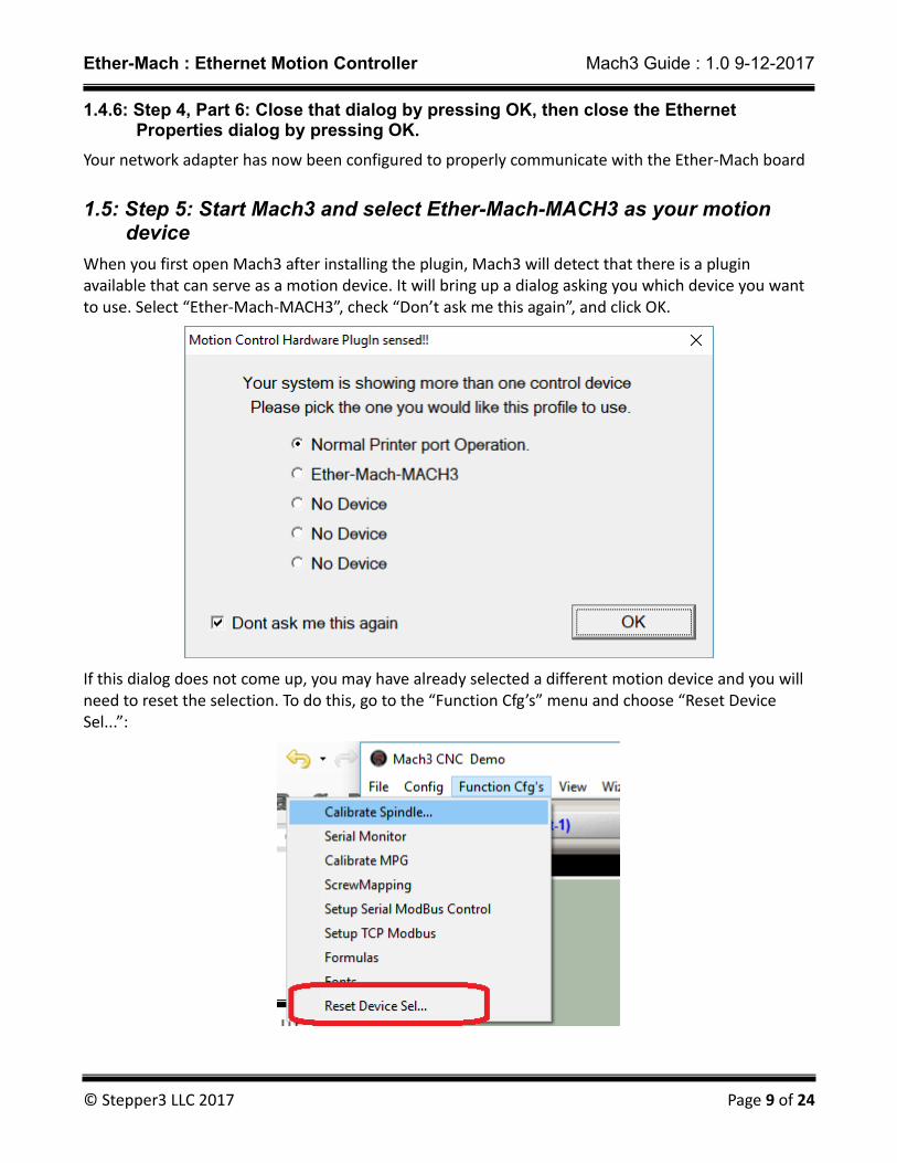
1.5: Step 5: Start Mach3 and select Ether-Mach-MACH3 as your motion device
When you first open Mach3 after installing the plugin, Mach3 will detect that there is a plugin available that can serve as a motion device. It will bring up a dialog asking you which device you want to use. Select “Ether-Mach-MACH3”, check “Don’t ask me this again”, and click OK.
If this dialog does not come up, you may have already selected a different motion device and you will need to reset the selection. To do this, go to the “Function Cfg’s” menu and choose “Reset Device Sel...”:
© Stepper3 LLC 2017 Page 9 of 24
Ether-Mach : Ethernet Motion Controller Mach3 Guide : 1.0 9-12-2017
After choosing “Reset Device Sel...” restart Mach3 and the motion control plugin selection dialog should appear.
Once you have selected “Ether-Mach-MACH3” as your motion device, restart Mach3 and it should load with the Ether-Mach plugin as its motion device. Upon startup (if you have not changed the default board IP address), you should successfully connect to the Ether-Mach board, indicated by a lack of error message boxes. (You can also check the connection LED on the board itself – see section 3). If the plugin fails to connect to the Ether-Mach board, a message box will appear with an error message stating that it timed out while trying to connect to the board.
© Stepper3 LLC 2017 Page 10 of 24
Ether-Mach : Ethernet Motion Controller Mach3 Guide : 1.0 9-12-2017
2: Mach3 Configuration
Mach3 was never designed to have a plugin architecture or to use motion devices other than its own parallel port driver. Support for motion plugins was added on later. This, combined with the fact that this is a back-port of a system for Mach4, means there are a few rough edges during setup. These are easy to handle, just make sure you read and take note of the contents of this section before you go to set up your machine.
2.1: Changing settings
Mach3 does not always inform the plugin of when you have changed certain settings. Due to this, some settings can only be loaded into the plugin and board on startup. This means that you will have to restart Mach3 after changing the settings in either the “General Config” or “Motor Tuning” dialogs. The plugin is notified of changes to the “Ports and Pins” dialog, so that can be changed freely without any restart.
2.2: Ignored settings
Some settings present in Mach3 are ignored by the plugin, in favor of configuration in the plugin’s ownconfiguration dialog.
The following settings in “Ports and Pins” are ignored:
• The Step Pin# and Dir Pin# on the Motor Outputs tab
• The Step Port and Dir Port on the Motor Outputs tab
• The Step Low Active option on the Motor Outputs tab
• The A-Port # and A-Pin # on the Encoders/MPG’s tab
• The B-Port # and B-Pin # on the Encoders/MPG’s tab
• PWMBase Freq and Minimum PWM on the Spindle Setup tab.
• Sherline ½ pulse mode on the Port Setup and Axis Selection tab.
On the “Motor Tuning” configuration dialog, the following options are ignored:
• “Step Pulse 1-5 us”
• “Dir Pulse 1-5 us”
• The entire Spindle axis motor tuning.
To configure most of these settings, use the plugin configuration dialog. To get to this dialog, choose the “PlugIn Control”→”Ether-Mach Plugin Settings” menu option. For details on the contents of the plugin configuration dialog, see the next section.
To configure the Spindle axis motor tuning, choose the “PlugIn Control”→”Ether-Mach Spindle Motor Settings” menu option to open the spindle motor configuration dialog. There, you can enter the steps per unit, velocity, and acceleration for your spindle motor:
© Stepper3 LLC 2017 Page 11 of 24

Ether-Mach : Ethernet Motion Controller Mach3 Guide : 1.0 9-12-2017
2.3: Motor Numbers
The Ether-Mach board, when running under Mach4, has support for 12 stepper motors. In the Ether-Mach plugin configuration dialog, these are referred to as Stepper 0 through 11. In Mach4, these 12 motors can be mapped to any number of axes in arbitrary ways.
In Mach3, things are different. Mach3 only supports exactly six coordinated axes plus the spindle motor and there is no logical separation between an axis and a motor. So, in Mach3, the axes and the motors (Stepper 0 through 11) have a fixed mapping as follows:
• Stepper 0 is the X axis/motor.
• Stepper 1 is the Y axis/motor.
• Stepper 2 is the Z axis/motor.
• Stepper 3 is the A axis/motor.
• Stepper 4 is the B axis/motor.
• Stepper 5 is the C axis/motor.
• Stepper 6 is the Spindle axis/motor.
All other motor outputs provided by Ether-Mach (Stepper 7 through 11) are ignored, unused, and unusable in Mach3.
When configuring the plugin, remember this relationship between the numbered step motors and Mach3’s axes!
© Stepper3 LLC 2017 Page 12 of 24

Ether-Mach : Ethernet Motion Controller Mach3 Guide : 1.0 9-12-2017
3: Plugin Configuration
To get your board up and running with Mach3, you will need to use the plugin’s configuration dialog tochoose certain settings. For example, this is where you will choose your step and direction pins. To get to the plugin configuration dialog, choose the “PlugIn Control”→”Ether-Mach Plugin Settings” menu option. In the rest of this section, the contents of each tab of this dialog will be explained.
3.1: General Settings
The general settings section is not important for most people – it is mostly settings for people who cannot use the default board IP settings. There are, however, four non-IP related settings.
The first is the Performance selector. Here, you can choose between High, Medium, and Low performance. These settings change both the rate at which the plugin sends IO updates to the board and the amount of motion that is queued on the board when running a file. Moving to a higher performance setting will increase the responsiveness of the system. We recommend using the highest performance value your computer can handle (in our experience, pretty much any newer desktop can run it on High) If, however, you have a computer that cannot keep up and you experience disconnects/dropouts, moving to a lower performance will often alleviate the problem.
The next setting is Hardware EStop on Disable. If this is enabled, an EStop not only stops the motion and the charge pump but also causes all outputs on the board to be set directly to ground at the board, overriding any values from Mach until the EStop ends.
After that, you have Perform EStop on Hard Limit. If this is checked, the Ether-Mach plugin will
© Stepper3 LLC 2017 Page 13 of 24
Ether-Mach : Ethernet Motion Controller Mach3 Guide : 1.0 9-12-2017
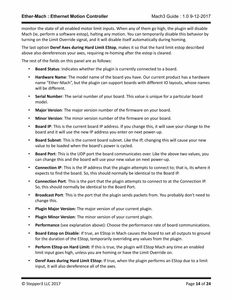
monitor the state of all enabled motor limit inputs. When any of them go high, the plugin will disable Mach (ie, perform a software estop), halting any motion. You can temporarily disable this behavior by turning on the Limit Override signal, and it will disable itself automatically during homing.
The last option Deref Axes during Hard Limit EStop, makes it so that the hard limit estop described above also dereferences your axes, requiring re-homing after the estop is cleared.
The rest of the fields on this panel are as follows:
• Board Status: Indicates whether the plugin is currently connected to a board.
• Hardware Name: The model name of the board you have. Our current product has a hardware name “Ether-Mach”, but the plugin can support boards with different IO layouts, whose nameswill be different.
• Serial Number: The serial number of your board. This value is unique for a particular board model.
• Major Version: The major version number of the firmware on your board.
• Minor Version: The minor version number of the firmware on your board.
• Board IP: This is the current board IP address. If you change this, it will save your change to theboard and it will use the new IP address you enter on next power-up.
• Board Subnet: This is the current board subnet. Like the IP, changing this will cause your new value to be loaded when the board's power is cycled.
• Board Port: This is the UDP port the board communicates over. Like the above two values, you can change this and the board will use your new value on next power-up.
• Connection IP: This is the IP address that the plugin attempts to connect to; that is, its where itexpects to find the board. So, this should normally be identical to the Board IP.
• Connection Port: This is the port that the plugin attempts to connect to at the Connection IP. So, this should normally be identical to the Board Port.
• Broadcast Port: This is the port that the plugin sends packets from. You probably don't need tochange this.
• Plugin Major Version: The major version of your current plugin.
• Plugin Minor Version: The minor version of your current plugin.
• Performance (see explanation above): Choose the performance rate of board communications.
• Board Estop on Disable: If true, an EStop in Mach causes the board to set all outputs to groundfor the duration of the EStop, temporarily overriding any values from the plugin.
• Perform EStop on Hard Limit: If this is true, the plugin will EStop Mach any time an enabled limit input goes high, unless you are homing or have the Limit Override on.
• Deref Axes during Hard Limit EStop: If true, when the plugin performs an EStop due to a limit input, it will also dereference all of the axes.
© Stepper3 LLC 2017 Page 14 of 24
Ether-Mach : Ethernet Motion Controller Mach3 Guide : 1.0 9-12-2017
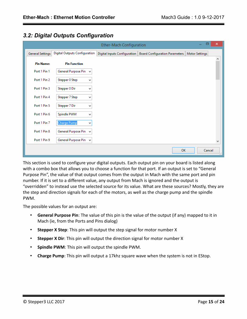
3.2: Digital Outputs Configuration
This section is used to configure your digital outputs. Each output pin on your board is listed along with a combo box that allows you to choose a function for that port. If an output is set to “General Purpose Pin”, the value of that output comes from the output in Mach with the same port and pin number. If it is set to a different value, any output from Mach is ignored and the output is “overridden” to instead use the selected source for its value. What are these sources? Mostly, they arethe step and direction signals for each of the motors, as well as the charge pump and the spindle PWM.
The possible values for an output are:
• General Purpose Pin: The value of this pin is the value of the output (if any) mapped to it in Mach (ie, from the Ports and Pins dialog)
• Stepper X Step: This pin will output the step signal for motor number X
• Stepper X Dir: This pin will output the direction signal for motor number X
• Spindle PWM: This pin will output the spindle PWM.
• Charge Pump: This pin will output a 17khz square wave when the system is not in EStop.
© Stepper3 LLC 2017 Page 15 of 24
Ether-Mach : Ethernet Motion Controller Mach3 Guide : 1.0 9-12-2017
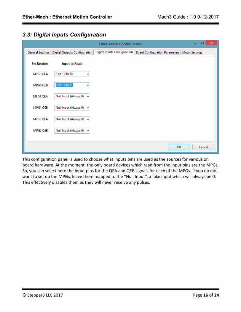
3.3: Digital Inputs Configuration
This configuration panel is used to choose what inputs pins are used as the sources for various on board hardware. At the moment, the only board devices which read from the input pins are the MPGs.So, you can select here the input pins for the QEA and QEB signals for each of the MPGs. If you do not want to set up the MPGs, leave them mapped to the “Null Input”, a fake input which will always be 0. This effectively disables them as they will never receive any pulses.
© Stepper3 LLC 2017 Page 16 of 24
Ether-Mach : Ethernet Motion Controller Mach3 Guide : 1.0 9-12-2017
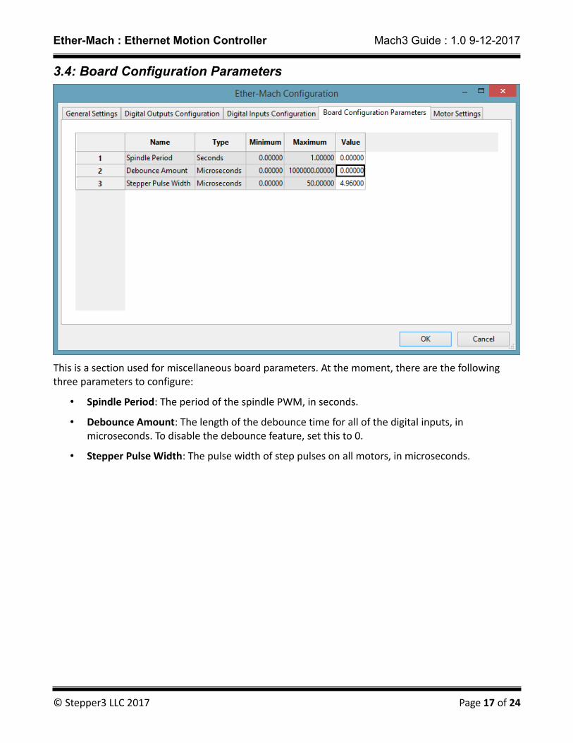
3.4: Board Configuration Parameters
This is a section used for miscellaneous board parameters. At the moment, there are the following three parameters to configure:
• Spindle Period: The period of the spindle PWM, in seconds.
• Debounce Amount: The length of the debounce time for all of the digital inputs, in microseconds. To disable the debounce feature, set this to 0.
• Stepper Pulse Width: The pulse width of step pulses on all motors, in microseconds.
© Stepper3 LLC 2017 Page 17 of 24
Ether-Mach : Ethernet Motion Controller Mach3 Guide : 1.0 9-12-2017
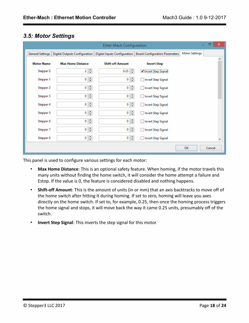
3.5: Motor Settings
This panel is used to configure various settings for each motor:
• Max Home Distance: This is an optional safety feature. When homing, if the motor travels this many units without finding the home switch, it will consider the home attempt a failure and Estop. If the value is 0, the feature is considered disabled and nothing happens.
• Shift-off Amount: This is the amount of units (in or mm) that an axis backtracks to move off of the home switch after hitting it during homing. If set to zero, homing will leave you axes directly on the home switch. If set to, for example, 0.25, then once the homing process triggersthe home signal and stops, it will move back the way it came 0.25 units, presumably off of the switch.
• Invert Step Signal: This inverts the step signal for this motor.
© Stepper3 LLC 2017 Page 18 of 24
Ether-Mach : Ethernet Motion Controller Mach3 Guide : 1.0 9-12-2017
3.6: Plugin Configuration Parameters
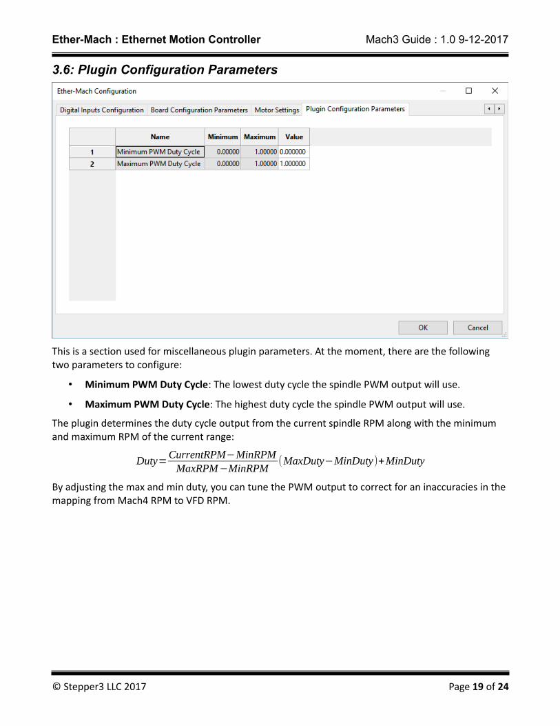
This is a section used for miscellaneous plugin parameters. At the moment, there are the following two parameters to configure:
• Minimum PWM Duty Cycle: The lowest duty cycle the spindle PWM output will use.
• Maximum PWM Duty Cycle: The highest duty cycle the spindle PWM output will use.
The plugin determines the duty cycle output from the current spindle RPM along with the minimum and maximum RPM of the current range:
Duty=CurrentRPM−MinRPMMaxRPM−MinRPM
(MaxDuty−MinDuty)+MinDuty
By adjusting the max and min duty, you can tune the PWM output to correct for an inaccuracies in the mapping from Mach4 RPM to VFD RPM.
© Stepper3 LLC 2017 Page 19 of 24

Ether-Mach : Ethernet Motion Controller Mach3 Guide : 1.0 9-12-2017
4: Torch Height Control
The Ether-Mach Mach3 plugin supports torch height control with antidive. To use THC, you must have all three of the THC On, THC Up, and THC Down inputs enabled and mapped to either a valid input pin or as an emulated input. Additionally, instead of using the default Plasma.set screenset, load the s3Plasma.set screenset that is included with the plugin installation. This screenset changes the correction amount DRO to point to a user DRO which the plugin loads with the current amount of correction being applied to the Z position.
Once it is set up correctly, use the THC button on the screenset to enter THC mode (or call the appropriate OEM button from your scripts). When THC mode is enabled, the plugin will save the current location as the reference point for THC, such that the THC Max and THC Min will specify the largest allowed deviation from that location. Just entering THC mode does not cause the Z axis to move – it only configures and enables it. Motion will begin once the THC On signal goes high.
If you are making or have a custom screenset and want to incorporate support for Ether-Mach THC, you can use the following DRO numbers to access information about the board THC state:
• 1101: This holds the current correction amount that is being applied to the Z axis.
• 1102: This holds the sum of the current correction amount and the Z position DRO, providing a DRO that contains the true current position of the Z axis.
© Stepper3 LLC 2017 Page 20 of 24
Ether-Mach : Ethernet Motion Controller Mach3 Guide : 1.0 9-12-2017
5: Breakout Board Information
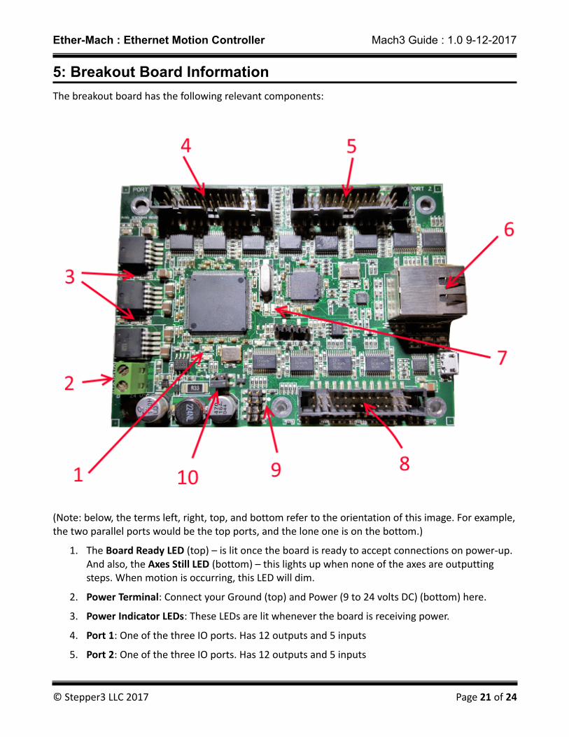
The breakout board has the following relevant components:
(Note: below, the terms left, right, top, and bottom refer to the orientation of this image. For example,the two parallel ports would be the top ports, and the lone one is on the bottom.)
1. The Board Ready LED (top) – is lit once the board is ready to accept connections on power-up. And also, the Axes Still LED (bottom) – this lights up when none of the axes are outputting steps. When motion is occurring, this LED will dim.
2. Power Terminal: Connect your Ground (top) and Power (9 to 24 volts DC) (bottom) here.
3. Power Indicator LEDs: These LEDs are lit whenever the board is receiving power.
4. Port 1: One of the three IO ports. Has 12 outputs and 5 inputs
5. Port 2: One of the three IO ports. Has 12 outputs and 5 inputs
© Stepper3 LLC 2017 Page 21 of 24

Ether-Mach : Ethernet Motion Controller Mach3 Guide : 1.0 9-12-2017
6. Ethernet Port: Connect your Ethernet cable here.
7. Board Status LEDs: These two LEDs (left and right) have many values:
1. Both off while Board Ready is on – the board is ready but not connected.
2. Left LED on – the board is connected and is currently enabled
3. Right LED on – the board is connected and is currently disabled
4. Both LEDs on – Critical board error; if this happens to you, tell us about it! These errors should not happen normally and are indicative of a firmware bug.
5. Left LED blinking – the board is currently in firmware update mode. See the firmware update section below.
6. Both blinking back and forth – the bootloader could not start the firmware. You likely need to re-flash the board to install valid firmware.
8. Port 3: One of the three IO ports. Has 12 outputs and 5 inputs.
9. Startup Control Switches: These 4 jumpers control the following settings:
1. Top jumper – Clear Settings: This is referred to as CLEAR_SETS in the firmware updater. If this jumper is on during startup, the IP address configuration is reset to the factory default. The board will go back to using 10.7.7.7 as its IP address.
2. 2nd one down – Does nothing. You can keep the jumper for Clear Settings here while not using it.
3. 3rd one down – Enter Bootloader. This is referred to as LOAD_FIRM in the firmware updater.If this jumper is on during startup, the board enters firmware update mode. If this jumper is added while the board is already on, it will enter firmware update mode after the jumperhas remained on for 5 seconds. If the jumper is removed, the board will exit firmware update mode and launch the installed firmware.
4. 4th one down – Does nothing. You can keep the jumper for Enter Bootloader here while not using it.
10. Port Voltage Select Jumpers: The top jumper selects 3.3v port IO, and the bottom jumper selects 5v port IO. Applying both jumpers simultaneously will permanently destroy the board!
On every parallel port header, pins 1, 2, 3, 4, 5, 6, 7, 8, 9, 14, 16, and 17 are outputs and pins 10, 11, 12, 13, and 15 are inputs.
5.1 Other Information
• Board Dimensions: 4.5 in x 3.35 in
• Distance between screws:
◦ Long side (corner to corner): 4.010 in
© Stepper3 LLC 2017 Page 22 of 24
Ether-Mach : Ethernet Motion Controller Mach3 Guide : 1.0 9-12-2017
◦ Short side (corner to corner): 2.8 in
◦ Corner to middle screw hole: 2.046 in
◦ Middle screw hole to other corner: 1.964 in
6. Updating Board Firmware
Stepper3 may provide firmware updates to the board with bug fixes or feature additions. We make a strong effort to avoid breaking compatibility with existing plugin version when do this, but it is sometimes unavoidable. So, in order to allow users to migrate to new firmware and plugin versions (ie, plugins built for new firmware), it is possible to update the firmware of a board.
In the Mach3 directory where the plugin was installed (default is C:\Mach 3) the installer also left behind a program executable named Ether-Mach-Firmware-Updater.exe. If you double click the program to run it, it will guide you step-by-step through the process of updating your firmware. The firmware updater installs the firmware version corresponding to the plugin it was installed with. If your board firmware is newer, not older, you don't need to change the firmware – just download the latest plugin from http://ether-mach.com.
7: Troubleshooting
I keep getting a message that it timed out while trying to connect to the Ether-Mach board.
Ensure that the board is powered and connected to the correct Ethernet port on your computer. Ensure that your network settings for that Ethernet port match the ones explained in section II. Ensurethat you do not have any other network adapters that are configured for the same subnet (default 10.7.7.0/24) as the adapter used to connect to the board.
When I start, I get a status message saying that my board is the wrong version.
Download and install the latest plugin from the Ether-Mach website. Then, follow the instructions in section 4 to run the firmware updater in order to update your board to the latest firmware.
My computer loses connection to the board after I have connected. OR The motion from the breakout board is skipping.
First, ensure that you have no applications running that could interfere with the communication to theboard, either by using too much CPU or by flooding the network adapter with packets. If that does notfix the problem, try lowering the Performance setting in the general settings tab of the plugin settings dialog.
I think I have found a bug in the plugin or breakout board.
If you believe you have found a bug, email [email protected] with as detailed a description as possible of what the issue you are having is. In particular, try to include the following details:
• The version of Mach you are using.
• The version of the Ether-Mach plugin and firmware that you are using.
© Stepper3 LLC 2017 Page 23 of 24

Ether-Mach : Ethernet Motion Controller Mach3 Guide : 1.0 9-12-2017
• Details on, or possibly the source of, any customizations to the screenset or macros that may be involved with the bug.
• Your Mach profile.
• Steps to reproduce the bug (be specific).
• A description of the software behavior you expected and then a description of the software behavior that actually occurred (that is, the bug).
• An email address at which we could best contact you.
© Stepper3 LLC 2017 Page 24 of 24