etag023-draft etag-06.11.23
TRANSCRIPT
8/14/2019 ETAG023-Draft etag-06.11.23
http://slidepdf.com/reader/full/etag023-draft-etag-061123 1/73
ETAG 023
Edition August 2006
GUIDELINE FOR EUROPEAN TECHNICAL APPROVAL
OF
PREFABRICATED BUILDING UNITS
©EOTA,
Kunstlaan 40 Avenue des Arts,B - 1000 Brussels
European Organisation for Technical Approvals
Europäische Organisation für Technische Zulassungen
Organisation Européenne pour l’Agrément Technique
8/14/2019 ETAG023-Draft etag-06.11.23
http://slidepdf.com/reader/full/etag023-draft-etag-061123 2/73
ETAG 232
TABLE OF CONTENTS
Table of contents _________________________________________________________________2
FOREWORD ______________________________________________________________________ 6Background to the subject ________________________________________________________6
Reference documents ___________________________________________________________6Updating conditions _____________________________________________________________7
Section one: INTRODUCTION _______________________________________________________8
1 PRELIMINARIES ______________________________________________________________8
1.1 Legal basis (to be finally written by EOTA Secretary General) _____________________8
1.2 Status of ETAG ____________________________________________________________8
2 SCOPE ______________________________________________________________________ 9
2.1 Scope ____________________________________________________________________ 9
2.2 Use categories, product families _____________________________________________ 9
2.3 Assumptions _____________________________________________________________103 TERMINOLOGY ______________________________________________________________11
3.1 Common terminology and abbreviations _____________________________________ 11
3.2 Specific terminology ______________________________________________________11
Section two: GUIDANCE FOR THE ASSESSMENT OF THE FITNESS FOR USE _____________ 12
GENERAL NOTES ________________________________________________________________12(a) Applicability of the ETAG __________________________________________________ 12(b) General layout of this section _______________________________________________ 12(c) Levels or classes or minimum requirements, related to the essential requirements and tothe product performance (see ID clause 1.2 and EC Guidance Paper E) __________________12(d) Working life (durability) and serviceability _____________________________________ 12(e) Fitness for the intended use ________________________________________________ 13
4 REQUIREMENTS _____________________________________________________________14
4.1 Mechanical resistance and stability (ER 1) ____________________________________ 16
4.2 Safety in case of fire (ER 2) _________________________________________________ 164.2.1 Reaction to Fire __________________________________________________________164.2.2 Resistance to Fire ________________________________________________________164.2.3 External fire performance of the roof covering __________________________________164.2.4 Fire compartmentation ____________________________________________________ 16
4.3 Hygiene, health and environment (ER 3) ______________________________________ 164.3.1 Vapour permeability and moisture resistance __________________________________16
4.3.2 Watertightness __________________________________________________________174.3.2.1 External envelope _______________________________________________________174.3.3 Release of dangerous substances ___________________________________________ 17
4.4 Safety in use (ER 4) _______________________________________________________174.4.1 Slipperiness of floor finishes ________________________________________________ 174.4.3 Resistance to eccentric loads including impact resistance. ________________________17
4.5 Protection against noise (ER 5) _____________________________________________ 184.5.1 Airborne sound insulation __________________________________________________ 184.5.2 Impact sound insulation ___________________________________________________ 184.5.3 Sound absorption ________________________________________________________18
4.6 Energy economy and heat retention (ER 6) ____________________________________ 184.6.1 Thermal resistance _______________________________________________________18
4.6.2 Air permeability __________________________________________________________184.6.3 Thermal inertia __________________________________________________________18
4.7 Aspects of durability, serviceability and identification __________________________18
8/14/2019 ETAG023-Draft etag-06.11.23
http://slidepdf.com/reader/full/etag023-draft-etag-061123 3/73
ETAG 233
4.7.1 Aspects of durability ______________________________________________________184.7.2 Aspects of serviceability ___________________________________________________ 184.7.3 Identification ____________________________________________________________18
5 METHODS OF VERIFICATION __________________________________________________ 19
5.1 Mechanical resistance and stability __________________________________________ 255.1.0 Verification of structural capacities in general __________________________________255.1.1 Indication of geometrical data _______________________________________________ 255.1.2 Verification by calculation __________________________________________________ 265.1.3 Verification by calculation assisted by testing __________________________________26
5.2 Safety in case of fire ______________________________________________________29
5.2.1.2.1 composite panels _____________________________________________________ 295.2.1.3 Classification as Class A1 _________________________________________________ 305.2.1.4 Classification without further testing _________________________________________ 305.2.2 Resistance to fire ________________________________________________________305.2.3 External fire performance of the roof covering __________________________________305.2.4 Fire compartmentation ____________________________________________________ 31
5.3 Hygiene, health and environment ____________________________________________ 31
5.3.1 Vapour permeability and moisture resistance _______________________________31
5.3.2 Watertightness __________________________________________________________315.3.3 Release of dangerous substances ___________________________________________ 325.3.3.1 _________________________ Presence of dangerous substances in the product
32
5.4 Safety in use _____________________________________________________________325.4.1 Slipperiness of floor finishes ________________________________________________ 325.4.2 Falling due to sudden changes in level or sudden drops __________________________335.4.3 Resistance to eccentric loads, including impact resistance. _______________________33
5.5 Protection against noise ___________________________________________________ 335.5.1 Airborne sound insulation ___________________________________________________ 335.5.2 Impact sound insulation ____________________________________________________ 335.5.3 Sound absorption _________________________________________________________34
5.6 Energy economy and heat retention _________________________________________ 345.6.1 Thermal resistance ________________________________________________________345.6.2 Air permeability ___________________________________________________________345.6.3.Thermal inertia ___________________________________________________________34
5.7 Durability, serviceability and identification ____________________________________ 355.7.1 Durability – General _______________________________________________________355.7.2 Aspects of serviceability ___________________________________________________ 375.7.3 Identification ____________________________________________________________37
6 ASSESSING AND JUDGING THE FITNESS FOR USE _______________________________38
6.1 Mechanical resistance and stability __________________________________________ 406.1.1 Mechanical Resistance and Stability __________________________________________ 40
6.1.1.1. Indication of geometrical data _____________________________________________ 406.1.1.2 Verification by calculation with or without assistance through testing ________________ 406.1.1.2.1 General ______________________________________________________________406.1.2 Structural capacities to be declared __________________________________________ 406.1.2.2 Specific notes regarding declared resistances _________________________________426.1.3 Resistance against seismic actions __________________________________________ 426.1.4 Structural analysis _______________________________________________________42
6.2 Safety in case of fire ______________________________________________________426.2.1 Reaction to fire __________________________________________________________426.2.2 Resistance to fire ________________________________________________________426.2.3 External fire performance __________________________________________________ 426.2.4 Fire compartmentation ____________________________________________________ 43
6.3 Hygiene, health and environment ____________________________________________ 436.3.1 Vapour permeability and moisture resistance __________________________________436.3.2 Watertightness __________________________________________________________436.3.3 Release of dangerous substances ___________________________________________ 43
8/14/2019 ETAG023-Draft etag-06.11.23
http://slidepdf.com/reader/full/etag023-draft-etag-061123 4/73
ETAG 234
6.4 Safety in use _____________________________________________________________436.4.1 Slipperiness of floor finishes ________________________________________________ 436.4.2 Falling due to changes in level or sudden drops ________________________________436.4.3 Resistance to eccentric loads, including impact resistance ________________________43
6.5 Protection against noise ___________________________________________________ 446.5.1 Airborne sound insulation ___________________________________________________ 446.5.2 Impact sound insulation ____________________________________________________ 446.5.3 Sound absorption _________________________________________________________44
6.6 Energy economy and heat retention _________________________________________ 44
6.6.1 Thermal resistance ______________________________________________________446.6.2 Air permeability __________________________________________________________446.6.3 Thermal inertia __________________________________________________________45
6.7 Durability, serviceability and identification ____________________________________ 45
6.7.1 Aspects of durability ____________________________________________________ 456.7.2 Aspects of serviceability ___________________________________________________ 456.7.3 Identification ____________________________________________________________45
7 ASSUMPTIONS AND RECOMMENDATIONS UNDER WHICH THE FITNESS FOR USE OFPREFABRICATED BUILDING UNITS IS ASSESSED ____________________________________ 46
7.0 General _________________________________________________________________46
7.1 Design of the works _______________________________________________________467.1.1 Local building regulations __________________________________________________ 467.1.2 Structural design _________________________________________________________467.1.3 Substructure ____________________________________________________________467.1.4 Ventilation ______________________________________________________________467.1.5 Rainwater systems ______________________________________________________46
7.2 Transport and storage _____________________________________________________ 47
7.3 Execution of works _______________________________________________________47
7.4 Maintenance and repair ____________________________________________________ 47
7.5 Re-location ______________________________________________________________47Section three: ATTESTATION OF CONFORMITY (AC) __________________________________48
Section four: ETA CONTENT _______________________________________________________55
9 THE ETA CONTENT ___________________________________________________________55
9.1 The ETA _________________________________________________________________55
9.1.1 Format ___________________________________________________________________559.1.4 Product characteristics ____________________________________________________ 559.1.5 Drawings _______________________________________________________________569.1.6 Erection details __________________________________________________________569.1.7 Estimated working life _____________________________________________________ 569.1.8 Maintenance ____________________________________________________________569.2 Supporting documents ____________________________________________________ 56
9.3 Additional information _____________________________________________________ 56
ANNEX A _______________________________________________________________________ 57
COMMON TERMINOLOGY AND ABBREVIATIONS ___________________________________ 571. Works and products ______________________________________________________572. Performance ____________________________________________________________573. ETAG-Format ___________________________________________________________584. Working life _____________________________________________________________585. Conformity ______________________________________________________________596. Approval and approved bodies ______________________________________________ 59Abbreviations _________________________________________________________________60
ANNEX B _______________________________________________________________________ 61
LIST OF REFERENCE STANDARDS _______________________________________________ 61Verification of loadbearing capacity ________________________________________________ 61
8/14/2019 ETAG023-Draft etag-06.11.23
http://slidepdf.com/reader/full/etag023-draft-etag-061123 5/73
ETAG 235
Verification of fire resistance and reaction to fire _____________________________________ 61Verification of resistance against weather effects _____________________________________ 61Verification of water vapour resistance _____________________________________________ 61Verification of safety in use ______________________________________________________62Verification of sound insulation performance ________________________________________ 62Verification of thermal insulation __________________________________________________ 62Verification of airtightness _______________________________________________________62Verification of durability _________________________________________________________62
Annex C ________________________________________________________________________ 64Test specification for verification of resistance to vertical loads _______________________64
C.1 Objective _______________________________________________________________64C.2 Test Specimen __________________________________________________________64C.3 Characterisation _________________________________________________________64C.4 Procedure ______________________________________________________________64C.5 Supplementary tests ______________________________________________________65
Annex D ________________________________________________________________________ 66
Test specification for verification of racking resistance of elements of building units. _______ 66
8/14/2019 ETAG023-Draft etag-06.11.23
http://slidepdf.com/reader/full/etag023-draft-etag-061123 6/73
ETAG 236
FOREWORD
Background to the subject
This Guideline has been drawn up by EOTA Working Group 02.02/01 – Prefabricated Building Units.
The Working Group consisted of members from 5 EC-countries; Germany, France, Belgium, theNetherlands, the Czech Republic and the United Kingdom. In addition, Austria, Denmark and Finland
have been corresponding members.
The Guideline sets out the performance requirements for Prefabricated Building Units, the verificationmethods used to examine the performance, the assessment methods used to evaluate theperformance for the intended use, and the presumed conditions for the design and installation of theproducts in the works.
Prefabricated Building Units, according to this Guideline are construction products, defined in theMandate (ref. Construct 01/503) as follows:
This Mandate covers those industrially prepared Building Units, marketed for use as buildings (singlyor in combination). The Building Units are intended for production in series and are made of pre-designed and pre-fabricated components. This mandate defines minimum requirements on the
contents of such Building Units. Units not meeting these minimum requirements are outside the scopeof this mandate and shall not be CE marked on the basis of the ETAG. These minimum requirementscomprise all of the following: the structural elements of the Building Units, the essential components of the external envelope including all necessary thermal insulation and the internal linings in so far asthey are necessary for the satisfaction of the Essential Requirements applied to the building See 2.1Scope regarding the assessment of ‘typical’ details).
The design process (including the approval of detailed plans, applications for planning permission,building permits, …) must comply with the procedures foreseen in the Member States in which thebuilding is to be built. This Mandate does not amend this process in any way. The completed building(the works) must comply with the building regulations (regulations on works) applicable in the Member States in which the building is to be constructed. The procedures foreseen in that Member State for demonstrating compliance with the building regulations must also be followed by the entity held
responsible for this act. This mandate does not amend this process in any way.Although some components may be prepared in different factories, only the final Building Unit for delivery, and not the different components, can be CE marked as a whole, under the responsibility of the ETA holder.
An ETA is a favourable technical assessment of a construction product for an intended use, ieincorporated in the works. The ETA deals only with the product, and states classes or productcharacteristics to be used by the designer of the works.The declared performance of the product must be compared with the relevant requirements in thebuilding regulations from case to case, taking into account the intended use in relation to type of building, site, etc.
Verification of the performance of Prefabricated Building Units requires an assessment of manyconstruction details. These include the performance of joints between prefabricated elements withrespect to air permeability and durability, the strength of lining materials with respect to impact loadsand safety in use, watertightness of internal wet areas, etc. Relevant standardised verificationmethods may not always be available or judged to be necessary since the performance of manyconstruction details has been proven to be acceptable by long-term experience from use in traditionaldesigns. In accordance with the general advice in the Format of Guidelines for ETA’s it is recognisedin this guideline that some product properties can be assessed by a pass/fail approach on the basis of engineering judgement and experience from the use of well-known materials and designs.
Reference documents
Reference documents are referred to within the body of the ETAG, and are subject to the specificconditions mentioned therein.
The list of reference documents for this ETAG is given in Annex B. When additional parts for thisETAG are written afterwards, they may comprise modifications to the list of reference documentsapplicable to that part.
8/14/2019 ETAG023-Draft etag-06.11.23
http://slidepdf.com/reader/full/etag023-draft-etag-061123 7/73
ETAG 237
Updating conditions
The edition of a reference document given in the list is that which has been adopted by EOTA for itsspecific use.When a new edition becomes available, this supersedes the edition mentioned in the list only whenEOTA has verified or re-established (possibly with appropriate linkage) its compatibility with theguideline.EOTA Comprehension Documents will permanently take on board all useful information on theupdating of reference documents and on the general understanding of this ETAG as developed when
delivering ETA’s in consensus by EOTA members.
EOTA Technical Reports go into detail in some aspects and as such are not part of the ETAG, butexpress the common understanding of existing knowledge and experience of the EOTA-bodies at thatmoment. When knowledge and experience is developing, especially through approval work, thesereports can be amended and supplemented. When this happens, the effect of the changes upon theETAG will be determined by EOTA and laid down in the relevant comprehension documents.
Readers and users of this ETAG are advised to check the current status of the content of thisdocument with an EOTA member.
8/14/2019 ETAG023-Draft etag-06.11.23
http://slidepdf.com/reader/full/etag023-draft-etag-061123 8/73
ETAG 238
SECTION ONE: INTRODUCTION
1 PRELIMINARIES
1.1 Legal basis
This ETA Guideline has been established in compliance with the provisions of the Council Directive89/106/EC and has been established taking into account the following steps:- the final mandate issued by the EC - 03/02/2003- the final mandate issued by EFTA – 03/02/2003- adoption of the Guideline by the Executive Commission of EOTA – November 2005- opinion of the Standing Committee for Construction – December 2005- endorsement by the EC – 19/09/2006
This document is published by the Member states in their official language or languages according toart. 11/3 of the CPD. No existing ETA guideline is superseded.
1.2 Status of ETAG
a. An ETA is one of the two types of technical specifications in the sense of the EC ConstructionProducts Directive (89/106/EEC). This means that Member States shall presume that the approvedPrefabricated Building Units are fit for their intended use, i.e. they enable works in which they areemployed to satisfy the essential requirements during an economically reasonable working life,provided that:- the works are properly designed and built;- the conformity of the products with the ETA has been properly attested.
b. This ETAG is a basis for ETA’s, i.e. a basis for technical assessment of the fitness for use of aproduct for an intended use. An ETAG is not itself a technical specification in the sense of the CPD.
This ETAG expresses the common understanding of the approval bodies, acting together withinEOTA, as to the provisions of the Construction Products Directive 89/106 and of the Interpretative
Documents, in relation to the product and uses concerned, and is written within the framework of amandate given by the Commission and the EFTA secretariat, after consulting the Standing Committeefor Construction.
c. When accepted by the European Commission after consultation with the Standing Committee for Construction this ETAG is binding for the issuing of ETA’s for Prefabricated Building Units for thedefined intended uses.
The application and satisfaction of the provisions of an ETAG (examinations, tests and evaluationmethods) leads to an ETA and a presumption of fitness of a product for the defined use only throughan evaluation an approval process and decision, followed by the corresponding attestation of conformity. This distinguishes an ETAG from a harmonised European standard, which is the directbasis for attestation of conformity.
Where appropriate, Prefabricated Building Units that are outside of the precise scope of this ETAGmay be considered through the approval procedure without guidelines according to art. 9.2 of theCPD.
The requirements in this ETAG are set out in terms of objectives and of relevant actions to be takeninto account. It specifies values and characteristics, the conformity with which gives the presumptionsthat the requirements set out are satisfied, wherever the state of art permits and after having beenconfirmed as appropriate for the particular product by the ETA.
This guideline indicates alternative possibilities for the demonstration of the satisfaction of therequirement.
8/14/2019 ETAG023-Draft etag-06.11.23
http://slidepdf.com/reader/full/etag023-draft-etag-061123 9/73
ETAG 239
2 SCOPE
2.1 Scope
Prefabricated Building Units, designed as box-like structures but transportable to site in flat-pack or three-dimensional format. The Units may form a building individually or in conjunction, horizontallyand/or vertically, with other units and rapidly provide a weatherproof envelope, possibly subject to final
weathering, jointing between units, connection to services and any foundation connections.
The structural elements are prefabricated1
and assembled in a factory. They usually comprise a frameof metal, metal and timber or concrete. Concrete Units
2may be monolithic or may comprise joined
panels. In some cases, prefabricated composite panels are part of the load bearing structure. Floorsmay be prefabricated, installed or, in the case of concrete, cast in-situ.
Building Units may be supplied with varying degrees of completion but all components required for structural stability (when the Units are assembled into a building) shall be included.There are a number of options for assessment available to the Approval Body, in discussion with theETA Applicant.
• If the Unit(s) under assessment is/are ‘complete’ as offered by the ETA applicant, i.e. allelements of the roof, walls etc are supplied, then a full evaluation can be made (taking
account of rules for joining Units together) and data presented accordingly, coveringweathertightness, acoustic performance, fire resistance etc, in addition to structural data.
• Where the Unit does not include all elements e.g. external cladding, roof covering, internallining, external cladding, flooring etc then the ETA Applicant may ask for assumptions to bemade about typical solutions. In this case the ETA shall make clear what assumptions havebeen made.
Where windows, door sets, the external skin (e.g. a brick outer leaf), and pitched roofs etc do not formpart of the product then the interface between these components and the Units shall always be subjectto assessment.
Prefabricated Building Units covered by this ETAG may be relocateable and intended for use in anybuilding subject to regulatory requirements. However, Units incorporating a permanently fixed wheelsystem are excluded from this Guideline. Complementary structures (including foundation or substructure) and Units for use in cold storage buildings
3are also excluded.
For some uses, other ancillary fittings and equipment will be required for the assembled building. Thesuitability of any particular piece of ancillary equipment required in this context will not be included inthe ETAG. Electrical and water services, sanitary equipment etc. will not be covered. The influence of any provisions for their incorporation, e.g. conduits/pipes or cut-outs in members, will be included inthe assessment.1The term ‘prefabricated’’ indicates that the products are manufactured using industrial series production or a process similar to
series production. ‘Similar’ in this context shall be taken to mean production on the basis of a pre-designed system.
2 Pre-cast concrete components should be assessed taking account of relevant harmonised standards, where applicable. A list
of such standards (not exhaustive) is included, for reference, in Annex B. When such components are assessed only as part of
the Unit, subsequent CE marking of the component itself is not permissible.
3 ETAG 021 makes reference to relevant sections of this ETAG to enable such Units to be assessed.
2.2 Use categories, product families
The product performance of Prefabricated Buildings Units in relation to the Essential Requirements willnormally be required to correspond with national regulatory requirements for the works relevant to theintended use of the product in, for example, dwellings, office buildings, schools, hospital and medicalbuildings, dormitories
3. These requirements will vary between the member states, and the product
performance shall be expressed in numerical terms. For performance in case of fire, standardEuropean fire classification is applied.
3
List not exhaustive.
8/14/2019 ETAG023-Draft etag-06.11.23
http://slidepdf.com/reader/full/etag023-draft-etag-061123 10/73
ETAG 2310
2.3 Assumptions
The state of the art does not enable the development, within a reasonable time, of full and detailedverification methods and corresponding technical criteria/guidance for acceptance for some particular aspects and products. This ETAG contains assumptions taking account of the state of art and makesprovisions for appropriate, additional case by case approaches when examining ETA-applications,within the general framework of the ETAG and under the CPD consensus procedure between EOTAmembers.
The guidance remains valid for other cases that do not deviate significantly. The general approach of the ETAG remains valid, but the provisions then need to be used case by case in an appropriate way.This use of the ETAG is the responsibility of the ETA-body that receives the special application, andsubject to consensus within EOTA. Experience in this respect is collected, after endorsement inEOTA-TB, in the ETAG Comprehension document.
8/14/2019 ETAG023-Draft etag-06.11.23
http://slidepdf.com/reader/full/etag023-draft-etag-061123 11/73
ETAG 2311
3 TERMINOLOGY
3.1 Common terminology and abbreviations
See Annex A
3.2 Specific terminology
Building Unit:
A Unit, defined as a construction product, and designed as a three-dimensional structure,transportable to site in three-dimensional or flat pack format and rapidly providing a weatherproof envelope, possibly subject to final weathering, jointing between Units, connection between Units andany foundation connections.
Design climatic conditions :Outdoor and indoor air temperature and moisture levels, snow loads, wind load, etc, which may bestated in national building regulations or in other specifications to be used for design.
Integrated components: Components such as windows, doors, conduits, etc that are built into the Building Units.
Joint/Connection :Junction between two materials, components, sub-structures or Building Units.
Substructure: The structural elements below the Building Unit(s), including the foundation, that transmit all loadsfrom the Units to the ground.
Pre-designed: Pre-determined technical solutions.
Production in series: Production of Building Units for a series of buildings on the basis of the same materials, structuraldesign and construction details. The buildings and components do not have to be exactly of the samesize or shape.
Production unit: Production line or facility where the product is manufactured and/or processed.
Separating walls and floors: Walls and floors where national regulations can require sound insulation, fire resistance performance,etc.
Supporting documents:
Documents included in the formal part of the approval, but where the content is not included in theETA-document itself. The valid version of a supporting document is the last updated version filed bythe approval body.
Suspended floors: Floor structures with a free span between supports.
UDL: Uniformly distributed load.
Wet area surface:Floors and wall areas in bathrooms and other “wet rooms” where the surface may be exposed to water spray from showers, etc, and where the ETA applicant declares the surfaces to be watertight.
8/14/2019 ETAG023-Draft etag-06.11.23
http://slidepdf.com/reader/full/etag023-draft-etag-061123 12/73
ETAG 2312
SECTION TWO: GUIDANCE FOR THE ASSESSMENT OF THE FITNESSFOR USE
GENERAL NOTES
(a) Applicability of the ETAG This ETAG provides guidance on the assessment of a family of prefabricated building units and their intended uses. It is the ETA applicant or producer who defines the family of products for which he isseeking an ETA and how it is to be used in the works, and consequently the scale of the assessment. It is therefore possible that for some prefabricated building units, which are fairly conventional, onlysome of the tests and corresponding criteria are necessary to establish fitness for use. In other cases,e.g. special or innovative products, or where there is a range of uses, the whole range of tests andassessment may be applicable.
(b) General layout of this section
The assessment of fitness of prefabricated building units with regard to their fitness for intended use in
construction works is a process with three main steps:- Chapter 4 clarifies the specific requirements for the works relevant to the Prefabricated Building
Units and uses concerned, beginning with the Essential Requirements for works (CPD art. 11.2)and then listing the corresponding relevant characteristics of the products.
- Chapter 5 extends the list in chapter 4 into more precise definitions and the methods available toverify product characteristics and to indicate how the requirements and the relevant productcharacteristics are described. This is done by test procedures, methods of calculation and other appropriate methods.
- Chapter 6 provides guidance on the assessing and judging methods to confirm fitness for theintended use of the prefabricated building units.
- Chapter 7, assumptions and recommendations are only relevant in as far as they concern the basisupon which the assessment of the prefabricated building units is made concerning their fitness for the intended use.
(c) Levels or classes or minimum requirements, related to the essential requirements and to the product performance (see ID clause 1.2 and EC Guidance Paper E)
According to the CPD “Classes” in this ETAG refer only to mandatory levels or classes laid down inthe EC-mandate.
This ETAG indicates however the compulsory way of expressing relevant performance characteristicsfor prefabricated building units. If, for some uses at least one Member state has no regulations, amanufacturer always has the right to opt out one or more of them, in which case the ETA will state “noperformance determined” against that aspect, except for those properties for which, when nodetermination has been made, the prefabricated building units does not any longer fall under the
scope of the ETAG; such cases shall be indicated in the ETAG.
(d) Working life (durability) and serviceability
The provisions, test and assessment methods in this guideline or referred to, have been written, basedupon the assumed intended working life of the prefabricated building units for the intended use of 50years for the loadbearing structure and for non-accessible components and materials, and 25 years for repairable or replaceable components and materials like such as claddings, roofing materials, exterior trims and integrated components such as windows and doors, provided that the product is subject toappropriate use and maintenance ( chapter. 7). An Applicant may request an ETA for Building Unitwith a shorter intended working life provided this can be justified in the proposed intended use.
The use of components and materials with shorter intended working life shall be clearly stated in the
ETA. These provisions are based upon the current state of art and the available knowledge andexperience.
8/14/2019 ETAG023-Draft etag-06.11.23
http://slidepdf.com/reader/full/etag023-draft-etag-061123 13/73
ETAG 2313
An “assumed intended working life” means that it is expected that, when an assessment following theETAG-provisions is made, and this working life has elapsed, the real working life may be, in normaluse conditions, considerably longer without major degradation affecting the essential requirements.
The indications given as to the working life of a Prefabricated Building Unit can not be interpreted as aguarantee given by the producer or the approval body. They should only be regarded as a means for the specifiers to choose the appropriate criteria for Prefabricated Building Units in relation to theexpected, economically reasonable working life of the works (based upon ID. Par. 5.2.2).
(e) Fitness for the intended use
According to the CPD it has to be understood that within the terms of this ETAG, products shall “havesuch characteristics that the works in which they are to be incorporated, assembled, applied or installed, can, if properly designed and built, satisfy the Essential Requirements” (CPD, art. 2.1).
Hence, the product must be suitable for use in construction works, in which (as a whole and in their separate parts) they are fit for their intended use, account being taken of economy, and in order tosatisfy the essential requirements. Such requirements must, subject to normal maintenance, besatisfied for an economically reasonable working life. The requirements generally concern actionswhich are foreseeable (CPD Annex 1, preamble).
8/14/2019 ETAG023-Draft etag-06.11.23
http://slidepdf.com/reader/full/etag023-draft-etag-061123 14/73
ETAG 2314
4 REQUIREMENTS
This chapter sets out the aspects of performance to be examined in order to satisfy the relevantEssential requirements, by:- expressing in more detail, within the scope of the ETAG, the relevant Essential Requirements of
the CPD in the Interpretative Documents and in the mandate, for works or parts of the works,taking into account the actions to be considered, as well as the expected durability andserviceability of the works.
- applying them to the scope of the ETAG (product and where appropriate its constituents,components and intended uses), and providing a list of relevant product characteristics and other applicable properties.
When a product characteristic or other applicable property is specific to one of the EssentialRequirements, it is dealt with in the appropriate place. If, however, the characteristic or property isrelevant to more than one Essential Requirement, it is addressed under the most important one withcross reference to the other(s). This is especially important where a manufacturer claims “Noperformance determined” for a characteristic or property under one Essential Requirement and it iscritical for the assessing and judging under another Essential Requirement. Similarly, characteristicsor properties which have a bearing on durability assessments may be dealt with under ER 1 to ER 6,with reference under 4.7. Where there is a characteristic which only relates to durability, this is dealtwith in 4.7.
This chapter also takes into account further requirements, if any (e.g. resulting from other ECDirectives), and identifies aspects of serviceability including specifying characteristics needed toidentify the products (cf. ETA-format par. II.2).
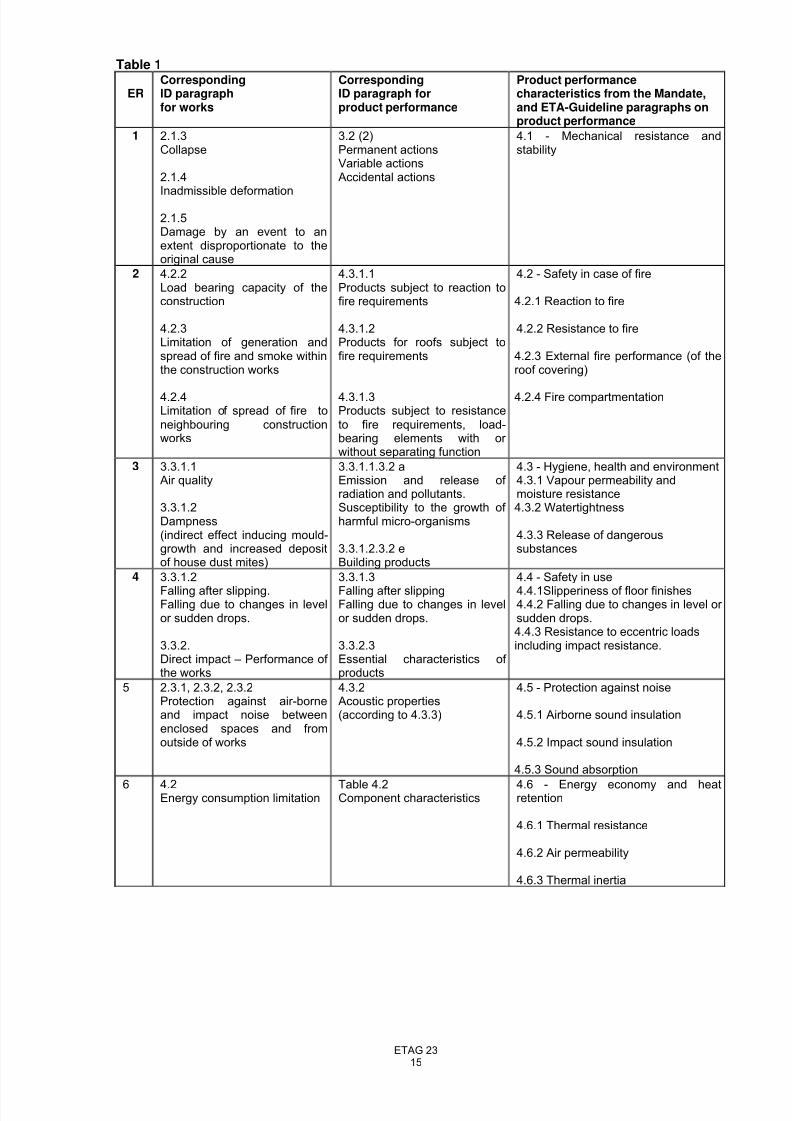
Table 1 on the next page shows the links between the Essential Requirements (ER) in the ECConstruction Products Directive (CPD), the relevant paragraphs of the corresponding InterpretativeDocuments (ID) to the CPD, and the related requirements and product performances in this ETAGuideline:
8/14/2019 ETAG023-Draft etag-06.11.23
http://slidepdf.com/reader/full/etag023-draft-etag-061123 15/73
ETAG 2315
Table 1
ER Corresponding ID paragraph for works
Corresponding ID paragraph for product performance
Product performancecharacteristics from the Mandate,and ETA-Guideline paragraphs onproduct performance
1 2.1.3 Collapse 2.1.4
Inadmissible deformation 2.1.5 Damage by an event to anextent disproportionate to theoriginal cause
3.2 (2) Permanent actions Variable actions Accidental actions
4.1 - Mechanical resistance andstability
2 4.2.2 Load bearing capacity of theconstruction 4.2.3 Limitation of generation andspread of fire and smoke withinthe construction works 4.2.4 Limitation of spread of fire toneighbouring constructionworks
4.3.1.1Products subject to reaction tofire requirements 4.3.1.2Products for roofs subject tofire requirements
4.3.1.3Products subject to resistanceto fire requirements, load-bearing elements with or without separating function
4.2 - Safety in case of fire 4.2.1 Reaction to fire 4.2.2 Resistance to fire 4.2.3 External fire performance (of theroof covering) 4.2.4 Fire compartmentation
3 3.3.1.1 Air quality 3.3.1.2 Dampness (indirect effect inducing mould-growth and increased depositof house dust mites)
3.3.1.1.3.2 aEmission and release of radiation and pollutants.Susceptibility to the growth of harmful micro-organisms 3.3.1.2.3.2 e Building products
4.3 - Hygiene, health and environment 4.3.1 Vapour permeability andmoisture resistance 4.3.2 Watertightness 4.3.3 Release of dangeroussubstances
4 3.3.1.2
Falling after slipping. Falling due to changes in levelor sudden drops. 3.3.2. Direct impact – Performance of the works
3.3.1.3
Falling after slippingFalling due to changes in levelor sudden drops. 3.3.2.3Essential characteristics of products
4.4 - Safety in use
4.4.1Slipperiness of floor finishes 4.4.2 Falling due to changes in level or sudden drops. 4.4.3 Resistance to eccentric loadsincluding impact resistance.
5 2.3.1, 2.3.2, 2.3.2 Protection against air-borneand impact noise betweenenclosed spaces and fromoutside of works
4.3.2 Acoustic properties (according to 4.3.3)
4.5 - Protection against noise 4.5.1 Airborne sound insulation 4.5.2 Impact sound insulation 4.5.3 Sound absorption
6 4.2 Energy consumption limitation
Table 4.2 Component characteristics
4.6 - Energy economy and heatretention 4.6.1 Thermal resistance 4.6.2 Air permeability 4.6.3 Thermal inertia
8/14/2019 ETAG023-Draft etag-06.11.23
http://slidepdf.com/reader/full/etag023-draft-etag-061123 16/73
ETAG 2316
4.1 Mechanical resistance and stability (ER 1)
The properties of the Building Units shall be such that when a building is constructed from them, inaccordance with the agreed assembly instructions and design rules, the loadings that are liable to acton it during construction and use will not lead to any of the following:
- collapse of the whole or part of the Works - major deformations to an inadmissible degree
- damage to other parts of the works or to fittings or installed equipment as a result of major deformation of the load-bearing construction
- damage by an event to an extent disproportionate to the original cause
4.2 Safety in case of fire (ER 2)
The Essential Requirement laid down in the Council Directive 89/106/EEC is as follows:
The construction works shall be designed and built in such a way that in the event of an outbreak of fire: - the load bearing capacity of the construction can be assumed for a specific period of time - the generation and spread of fire and smoke within the works are limited - the spread of fire to neighbouring construction works is limited
- occupants can leave the works or be rescued by other means - the safety of rescue teams is taken into consideration
The following aspects of performance are relevant to this Essential Requirement for PrefabricatedBuilding Units:
4.2.1 Reaction to Fire
The reaction to fire performance of the individual components of the Units shall be in accordance withlaws, regulations and administrative provisions applicable to the product in its intended end useapplication. This performance shall be expressed in the form of a classification specified in accordancewith the relevant EC decision and the appropriate CEN classification standards.
4.2.2 Resistance to Fire The resistance to fire performance of the Units shall be in accordance with laws, regulations andadministrative provisions applicable the product in its intended end use application. This performanceshall be expressed in the form of a classification specified in accordance with the relevant EC decisionand the appropriate CEN classification standards
4.2.3 External fire performance of the roof covering
The external fire performance of the roof covering of the Building Unit shall be in accordance withlaws, regulations and administrative provisions applicable to the product in its intended end useapplication. This performance shall be expressed in the form of a classification specified in accordancewith the relevant EC decision and the appropriate CEN classification standards.
4.2.4 Fire compartmentation
The fire compartmentation of an assembled building shall be in accordance with laws, regulations andadministrative provisions applicable to Works where the building is to be constructed.
4.3 Hygiene, health and environment (ER 3)
4.3.1 Vapour permeability and moisture resistance
The properties of the Units shall be such that there will be no threat to the occupants or neighboursdue to the [presence of damp in the works or on surfaces within the works formed from the Units.
8/14/2019 ETAG023-Draft etag-06.11.23
http://slidepdf.com/reader/full/etag023-draft-etag-061123 17/73
ETAG 2317
4.3.2 Watertightness
4.3.2.1 External envelope
The external envelope including joints between Units shall prevent leakage of water from rain andmelting snow into the works.
4.3.2.2 Internal surfaces
Internal wall and floor surfaces in bathrooms, toilets, etc claimed to be watertight by the ETA applicant,shall be sufficiently tight to avoid water penetration to rooms below (short-term effects) and to avoidmoisture levels in materials and components which may lead to unacceptable growth of micro-organisms (long-term effects). Where wet surfaces are shared between adjacent Units, the joint shallbe watertight.
4.3.3 Release of dangerous substances
The product shall be such that, when installed according to the appropriate provisions of the Member States, it allows for the satisfaction of the ER3 of the CPD as expressed by the national provisions of the Member States and in particular does not cause harmful emission of toxic gases, dangerousparticles or radiation to the indoor environment nor contamination of the outdoor environment (air, soilor water).
4.4 Safety in use (ER 4)
4.4.1 Slipperiness of floor finishes
To limit accidental falls in buildings under normal use, finished floor surfaces shall not be unacceptablyslippery and any unexpected change of slipperiness shall be avoided.
4.4.2 Falling due to changes in level or sudden drops.
Prefabricated Building Units or buildings formed from the Units shall be so designed that the risk tooccupants by falling due to changes in level or sudden drops is minimised. This can be achieved by
minimising the hazard itself or ensuring that protective measures are used.To protect persons against falling appropriate guardrails, balustrades or parapets can protectaccessible openings. Appropriate stairways, fixed ladders, ramps can be used at changes in levelsand appropriate safety catches and hinges can be used on windows in upper storeys. Such measuresshall meet with regulatory requirements where the building is erected.
4.4.3 Resistance to eccentric loads including impact resistance.
The Units shall have sufficient mechanical resistance and stability to ensure that the safety of theoccupants is not endangered (See also ER1). This means that they shall have sufficient mechanicalresistance and stability to withstand accidentally large static or dynamic loads, such as can arise fromthe action of persons or objects, without full or partial collapse. Equally, such loads shall not lead tothe production of dangerous (sharp or cutting) fragments, give rise to a risk of falling through,particularly at a change of level, nor endanger the safety of other people in or around the building.
The loads may be in the form of:
- impacts resulting from a person falling against the wall
- differential air pressure
- a large number of people leaning or pressing against the wall at the same time(crowd pressure)
- impacts resulting from the movement of heavy non-deformable objects such aspieces of furniture or equipment
- slamming of doors
- heavy objects such as furniture and sanitary or heating fixtures.
8/14/2019 ETAG023-Draft etag-06.11.23
http://slidepdf.com/reader/full/etag023-draft-etag-061123 18/73
ETAG 2318
4.5 Protection against noise (ER 5)
4.5.1 Airborne sound insulation
Walls and floors shall provide the necessary airborne sound insulation applicable to the intended useof the building.
The external envelope shall provide the necessary sound insulation applicable to the intended use of
the building concerning airborne noise from the outside (i.e. noise from industry, road and air traffic,etc).
4.5.2 Impact sound insulation
Floors shall provide the necessary impact sound insulation applicable to the intended use of thebuilding.
4.5.3 Sound absorption
Internal surfaces that are part of the unit shall provide the necessary sound absorption applicable tothe intended use of the building.
4.6 Energy economy and heat retention (ER 6)
4.6.1 Thermal resistance
The external envelope shall provide the necessary thermal insulation that is applicable to the intendeduse of the building. Thermal bridges, which may cause uncomfortably low temperatures or water vapour condensation affecting hygiene, health and environment related to ER 3, shall be avoided.
4.6.2 Air permeability
The external envelope shall provide adequate airtightness to limit unnecessary energy loss and toprevent cold draughts which may affect persons health in relation to ER 3.
4.6.3 Thermal inertia
Thermal inertia of the main building parts shall be known, where applicable, to assess the effect onenergy and heat retention.
4.7 Aspects of durability, serviceability and identification
4.7.1 Aspects of durability
The design of the Prefabricated Building Unit shall ensure that deterioration of materials andcomponents during the assumed intended working life does not significantly affect the performance of the product in relation to fulfilling all the Essential Requirements 1 – 6. Deterioration may be caused byphysical, biological and chemical agents.
4.7.2 Aspects of serviceability
Load bearing elements shall have sufficient stiffness to avoid unacceptable deflections and dynamiceffects from normal use. Units shall have adequate resistance to loads imposed during transportationand installation.
4.7.3 Identification
The materials used in Prefabricated Building Units shall be identifiable in relation to those propertiesthat have an influence on the ability of the product to fulfil the Essential Requirements.
8/14/2019 ETAG023-Draft etag-06.11.23
http://slidepdf.com/reader/full/etag023-draft-etag-061123 19/73
ETAG 2319
5 METHODS OF VERIFICATION
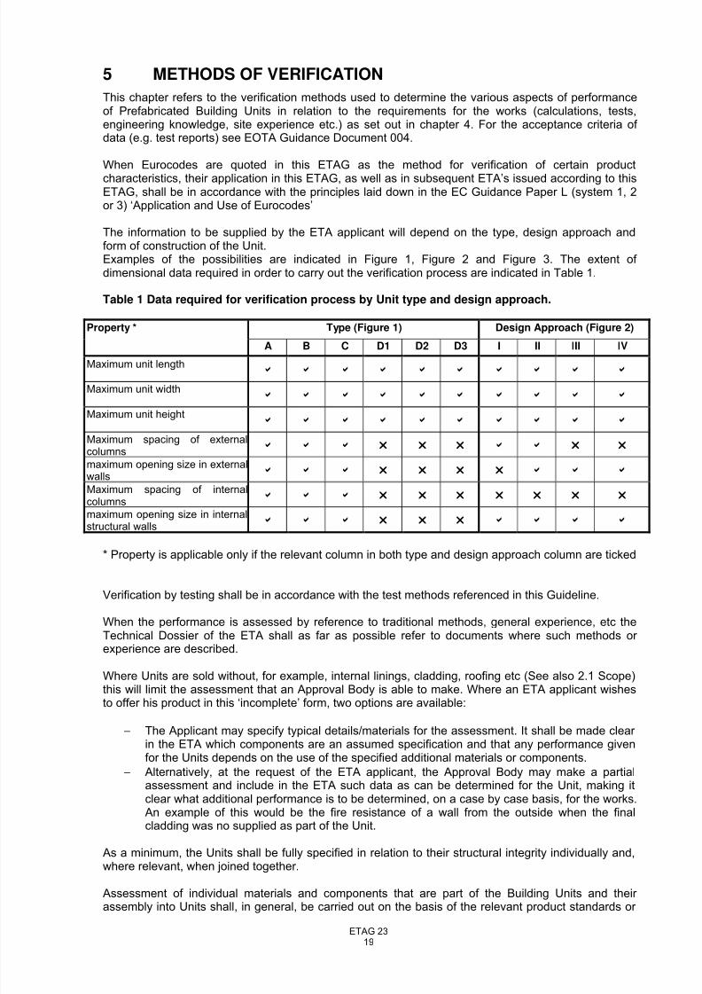
This chapter refers to the verification methods used to determine the various aspects of performanceof Prefabricated Building Units in relation to the requirements for the works (calculations, tests,engineering knowledge, site experience etc.) as set out in chapter 4. For the acceptance criteria of data (e.g. test reports) see EOTA Guidance Document 004.
When Eurocodes are quoted in this ETAG as the method for verification of certain product
characteristics, their application in this ETAG, as well as in subsequent ETA’s issued according to thisETAG, shall be in accordance with the principles laid down in the EC Guidance Paper L (system 1, 2or 3) ‘Application and Use of Eurocodes’
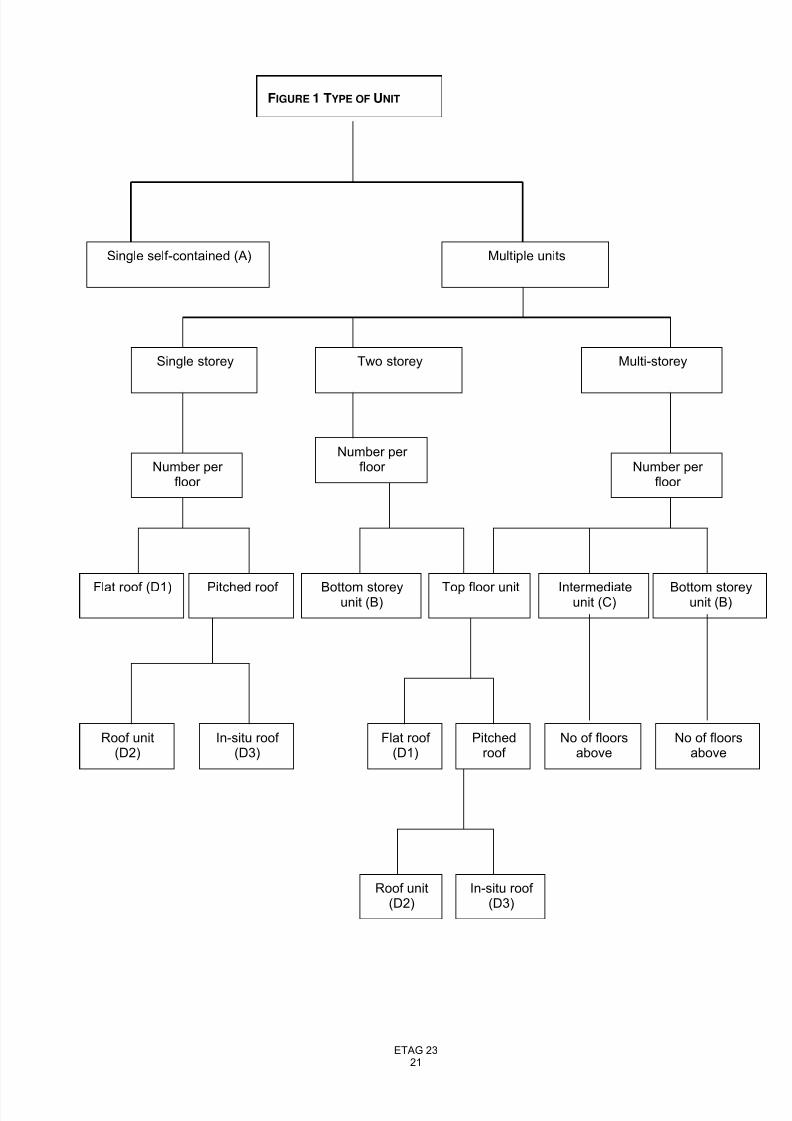
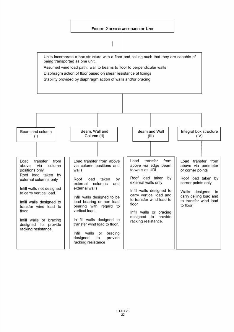
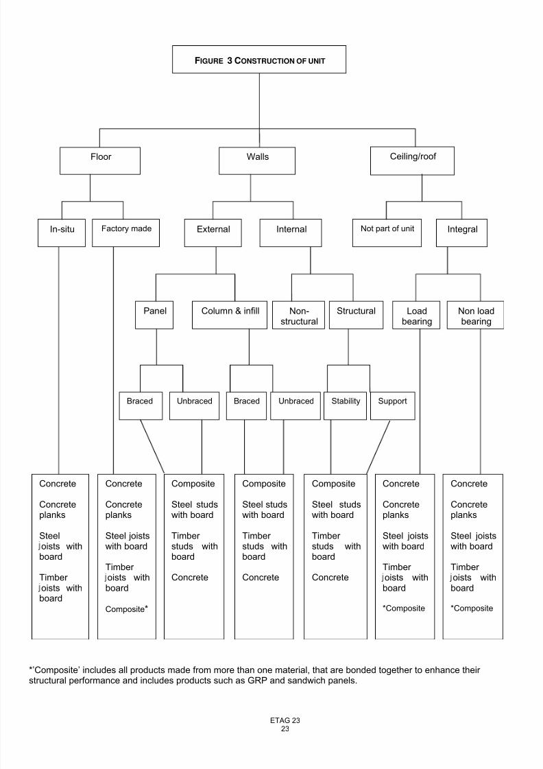
The information to be supplied by the ETA applicant will depend on the type, design approach andform of construction of the Unit.Examples of the possibilities are indicated in Figure 1, Figure 2 and Figure 3. The extent of dimensional data required in order to carry out the verification process are indicated in Table 1.
Table 1 Data required for verification process by Unit type and design approach.
Type (Figure 1) Design Approach (Figure 2)Property *
A B C D1 D2 D3 I II III IVMaximum unit length
b b b b b b b b b b
Maximum unit widthb b b b b b b b b b
Maximum unit heightb b b b b b b b b b
Maximum spacing of externalcolumns b b b r r r b b r r
maximum opening size in externalwalls b b b r r r r b b b
Maximum spacing of internalcolumns b b b r r r r r r r
maximum opening size in internalstructural walls b b b r r r b b b b
* Property is applicable only if the relevant column in both type and design approach column are ticked
Verification by testing shall be in accordance with the test methods referenced in this Guideline.
When the performance is assessed by reference to traditional methods, general experience, etc theTechnical Dossier of the ETA shall as far as possible refer to documents where such methods or experience are described.
Where Units are sold without, for example, internal linings, cladding, roofing etc (See also 2.1 Scope)this will limit the assessment that an Approval Body is able to make. Where an ETA applicant wishesto offer his product in this ‘incomplete’ form, two options are available:
− The Applicant may specify typical details/materials for the assessment. It shall be made clear in the ETA which components are an assumed specification and that any performance givenfor the Units depends on the use of the specified additional materials or components.
− Alternatively, at the request of the ETA applicant, the Approval Body may make a partialassessment and include in the ETA such data as can be determined for the Unit, making itclear what additional performance is to be determined, on a case by case basis, for the works.An example of this would be the fire resistance of a wall from the outside when the finalcladding was no supplied as part of the Unit.
As a minimum, the Units shall be fully specified in relation to their structural integrity individually and,
where relevant, when joined together.
Assessment of individual materials and components that are part of the Building Units and their assembly into Units shall, in general, be carried out on the basis of the relevant product standards or
8/14/2019 ETAG023-Draft etag-06.11.23
http://slidepdf.com/reader/full/etag023-draft-etag-061123 20/73
ETAG 2320
approvals for these products, or as far as possible on the basis of technical specifications for productswith the same intended use.
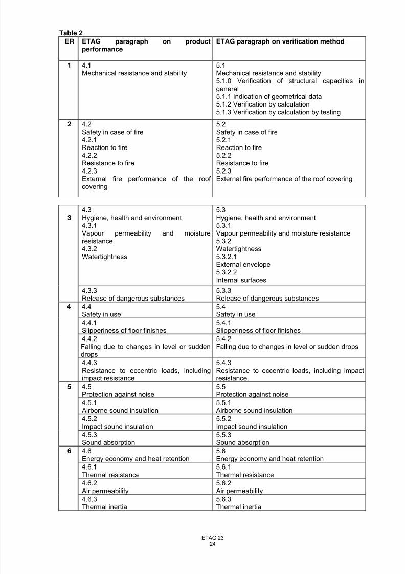
The relationship between the product performance characteristics and the corresponding paragraphson verification methods are summarised in Table 2
8/14/2019 ETAG023-Draft etag-06.11.23
http://slidepdf.com/reader/full/etag023-draft-etag-061123 21/73
ETAG 2321
FIGURE 1 TYPE OF UNIT
Single self-contained (A) Multiple units
Multi-storeyTwo storey
Number per floor
Number per floor
Single storey
Number per floor
Flat roof (D1) Pitched roof
In-situ roof (D3)
Roof unit(D2)
Bottom storeyunit (B)
Flat roof (D1)
Pitchedroof
In-situ roof (D3)
Roof unit(D2)
Top floor unit Intermediateunit (C)
Bottom storeyunit (B)
No of floorsabove
No of floorsabove
8/14/2019 ETAG023-Draft etag-06.11.23
http://slidepdf.com/reader/full/etag023-draft-etag-061123 22/73
ETAG 2322
Load transfer fromabove via columnpositions only
Roof load taken byexternal columns only
Infill walls not designedto carry vertical load.
Infill walls designed totransfer wind load tofloor.
Infill walls or bracingdesigned to provideracking resistance.
Load transfer fromabove via edge beamto walls as UDL
Roof load taken byexternal walls only
Infill walls designed tocarry vertical load andto transfer wind load tofloor
Infill walls or bracingdesigned to provideracking resistance.
Load transfer from abovevia column positions andwalls
Roof load taken byexternal columns andexternal walls
Infill walls designed to beload bearing or non loadbearing with regard tovertical load.
In fill walls designed totransfer wind load to floor.
Infill walls or bracingdesigned to provideracking resistance
Load transfer fromabove via perimeter or corner points
Roof load taken bycorner points only
Walls designed tocarry ceiling load andto transfer wind loadto floor
FIGURE 2 DESIGN APPROACH OF UNIT
Beam and Wall(III)
Beam, Wall andColumn (II)
Beam and column(I)
Units incorporate a box structure with a floor and ceiling such that they are capable of being transported as one unit.
Assumed wind load path: wall to beams to floor to perpendicular walls
Diaphragm action of floor based on shear resistance of fixings
Stability provided by diaphragm action of walls and/or bracing
Integral box structure(IV)
8/14/2019 ETAG023-Draft etag-06.11.23
http://slidepdf.com/reader/full/etag023-draft-etag-061123 23/73
ETAG 2323
FIGURE 3 CONSTRUCTION OF UNIT
Ceiling/roof WallsFloor
StructuralNon-structural
SupportStability
Non loadbearing
Loadbearing
External Internal Not part of unit IntegralIn-situ Factory made
Concrete
Concreteplanks
Steeloists withboard
Timber oists withboard
Concrete
Concreteplanks
Steel joistswith board
Timber oists withboard
Composite*
Composite
Steel studswith board
Timber studs withboard
Concrete
Composite
Steel studswith board
Timber studs withboard
Concrete
Concrete
Concreteplanks
Steel joistswith board
Timber oists withboard
*Composite
Panel Column & infill
Braced Unbraced Braced Unbraced
Concrete
Concreteplanks
Steel joistswith board
Timber oists withboard
*Composite
Composite
Steel studswith board
Timber studs withboard
Concrete
*’Composite’ includes all products made from more than one material, that are bonded together to enhance their structural performance and includes products such as GRP and sandwich panels.
8/14/2019 ETAG023-Draft etag-06.11.23
http://slidepdf.com/reader/full/etag023-draft-etag-061123 24/73
ETAG 2324
Table 2
ER ETAG paragraph on productperformance
ETAG paragraph on verification method
1
4.1 Mechanical resistance and stability
5.1 Mechanical resistance and stability 5.1.0 Verification of structural capacities ingeneral 5.1.1 Indication of geometrical data 5.1.2 Verification by calculation 5.1.3 Verification by calculation by testing
2
4.2 Safety in case of fire 4.2.1 Reaction to fire 4.2.2 Resistance to fire 4.2.3 External fire performance of the roof covering
5.2 Safety in case of fire 5.2.1 Reaction to fire 5.2.2 Resistance to fire 5.2.3 External fire performance of the roof covering
3
4.3 Hygiene, health and environment 4.3.1 Vapour permeability and moistureresistance 4.3.2 Watertightness
5.3 Hygiene, health and environment 5.3.1 Vapour permeability and moisture resistance 5.3.2 Watertightness 5.3.2.1 External envelope 5.3.2.2 Internal surfaces
4.3.3
Release of dangerous substances
5.3.3
Release of dangerous substances 4 4.4 Safety in use
5.4 Safety in use
4.4.1 Slipperiness of floor finishes
5.4.1 Slipperiness of floor finishes
4.4.2 Falling due to changes in level or suddendrops
5.4.2 Falling due to changes in level or sudden drops
4.4.3 Resistance to eccentric loads, includingimpact resistance
5.4.3 Resistance to eccentric loads, including impactresistance.
5 4.5 Protection against noise
5.5 Protection against noise
4.5.1 Airborne sound insulation
5.5.1 Airborne sound insulation
4.5.2 Impact sound insulation
5.5.2 Impact sound insulation
4.5.3 Sound absorption
5.5.3 Sound absorption
6 4.6 Energy economy and heat retention
5.6 Energy economy and heat retention
4.6.1 Thermal resistance
5.6.1 Thermal resistance
4.6.2 Air permeability
5.6.2 Air permeability
4.6.3 Thermal inertia
5.6.3 Thermal inertia
8/14/2019 ETAG023-Draft etag-06.11.23
http://slidepdf.com/reader/full/etag023-draft-etag-061123 25/73
ETAG 2325
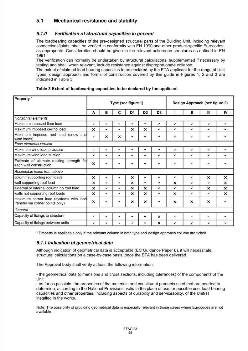
5.1 Mechanical resistance and stability
5.1.0 Verification of structural capacities in general
The loadbearing capacities of the pre-designed structural parts of the Building Unit, including relevantconnections/joints, shall be verified in conformity with EN 1990 and other product-specific Eurocodes,as appropriate. Consideration should be given to the relevant actions on structures as defined in EN1991.
The verification can normally be undertaken by structural calculations, supplemented if necessary bytesting and shall, when relevant, include resistance against disproportionate collapse.The extent of claimed load bearing capacities to be declared by the ETA applicant for the range of Unittypes, design approach and forms of construction covered by this guide in Figures 1, 2 and 3 areindicated in Table 3
Table 3 Extent of loadbearing capacities to be declared by the applicant
Type (see figure 1) Design Approach (see figure 2)Property *
A B C D1 D2 D3 I II III IV
Horizontal elements
Maximum imposed floor load b b b b b b b b b b
Maximum imposed ceiling load r b b r r b b b b b
Maximum imposed roof load (snow andwind loads) b r r b b b b b b b
Face elements vertical
Maximum wind load pressure b b b b b b b b b b
Maximum wind load suction b b b b b b b b b b
Estimate of ultimate racking strength for each wall construction. r b b b b b b b b b
Acceptable loads from above
column supporting roof loads r b b r b b b b r r
wall supporting roof load r b b r b b r b b rexternal or internal column no roof load r b b r r b b b r r
walls not supporting roof loads r b b r r b r b b r
maximum corner load (systems with loadtransfer via corner points only) r b b r r b r r r b
General
Capacity of fixings to structureb b b b b r b b b b
Capacity of fixings between units b b b b b r b b b b
* Property is applicable only if the relevant column in both type and design approach column are ticked
5.1.1 Indication of geometrical data
Although indication of geometrical data is acceptable (EC Guidance Paper L), it will necessitatestructural calculations on a case-by-case basis, once the ETA has been delivered.
The Approval body shall verify at least the following information:
- the geometrical data (dimensions and cross sections, including tolerances) of the components of theUnit- as far as possible, the properties of the materials and constituent products used that are needed todetermine, according to the National Provisions, valid in the place of use, or possible use, load-bearingcapacities and other properties, including aspects of durability and serviceability, of the Unit(s)installed in the works.
Note: The possibility of providing geometrical data is especially relevant in those cases where Eurocodes are notavailable
8/14/2019 ETAG023-Draft etag-06.11.23
http://slidepdf.com/reader/full/etag023-draft-etag-061123 26/73
ETAG 2326
5.1.2 Verification by calculation
Calculations shall be made according to the relevant parts of the appropriate Eurocode for thematerials used in each component of the structure:
The relevant Eurocodes (numbers to be amended if necessary) are:
- EN 1992, EN 1993, EN 1994, EN 1995 and EN 1999
If other structural materials are used for the components, the relevant Eurocode, European TechnicalApproval or other European Specification should be used.
Detailed calculation relating to the relevant actions on structures shall be performed and shall includechecks to establish the resistance to the Ultimate Limit State (collapse) and the Serviceability LimitState (deflection). Such calculations shall be performed on the maximum building unit size and will,depending on the structural system, normally include:
Checks on the adequacy of floor joists and floorboardsChecks to establish adequacy of diaphragm action of floor(s)Checks on the adequacy of ring beams to upper floorsChecks on the adequacy of main columnsChecks on the adequacy of wall units or wall studs, as appropriate
Checks on the support provided by diagonal bracing, where appropriateChecks on the adequacy of lintel detail(s) for maximum openingChecks on the adequacy of ground floor ring beamChecks on the suitability of roof trusses and connectionsChecks on the resistance to loading during transportation/installation.Checks on the structural adequacy of the connection details at the following junctions:
• wall panels to corner columns• roof frame to wall panel/columns• upper storey units to lower storey units• ground floor units to foundation• transmission of load above door and window opening• panel to panel connection• floor board to joists and joists to ring beam or wall panel
• brick ties where applicable• wall panels to supporting studs• bracing fixing
Overall stability checks, where appropriate (e.g. where the building is a single unit), should be carriedout utilising conventional structural analysis. Stability of multiple unit construction is the responsibilityof the building designer, using relevant performance data and connection rules for the Units. Seechapter 7.
Notes:1. Checks are necessary for each of the different unit types. (Examples of the possible Unit types and
forms of construction are given in Figures 1, 2 and 3.)2. Supplementary calculations, which are relevant for the resistance against seismic actions, should
be made according to the provisions in EN 1998, for various materials and elements. Other information on capacities against seismic actions based on Nationally Determined Parameters or other national regulations may be undertaken as a basis for the specific structural design for eachbuilding.
5.1.3 Verification by calculation assisted by testing
5.1.3.1 General
Evaluation by testing can be used to establish characteristic values for elements of the Building Unit or of the complete Unit.
Such tests shall be carried out in accordance with the relevant Eurocode or other European technicalspecification to verify or calibrate a theoretical static model of the Building Unit or element, or to deriveproperties where calculation is not practical or possible for particular properties
8/14/2019 ETAG023-Draft etag-06.11.23
http://slidepdf.com/reader/full/etag023-draft-etag-061123 27/73
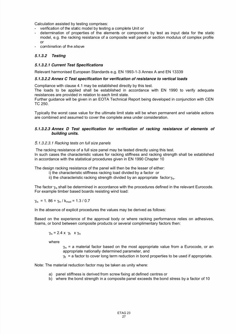
ETAG 2327
Calculation assisted by testing comprises:- verification of the static model by testing a complete Unit or - determination of properties of the elements or components by test as input data for the static
model, e.g. the racking resistance of a composite wall panel or section modulus of complex profileor
- combination of the above
5.1.3.2 Testing
5.1.3.2.1 Current Test Specifications
Relevant harmonised European Standards e.g. EN 1993-1-3 Annex A and EN 13339
5.1.3.2.2 Annex C Test specification for verification of resistance to vertical loads
Compliance with clause 4.1 may be established directly by this test.The loads to be applied shall be established in accordance with EN 1990 to verify adequateresistances are provided in relation to each limit state.Further guidance will be given in an EOTA Technical Report being developed in conjunction with CENTC 250.
Typically the worst case value for the ultimate limit state will be when permanent and variable actions
are combined and assumed to cover the complete area under consideration.
5.1.3.2.3 Annex D Test specification for verification of racking resistance of elements of building units.
5 .1.3.2.3.1 Racking tests on full size panels
The racking resistance of a full size panel may be tested directly using this test.In such cases the characteristic values for racking stiffness and racking strength shall be establishedin accordance with the statistical procedures given in EN 1990 Chapter 10
The design racking resistance of the panel will then be the lesser of either:i) the characteristic stiffness racking load divided by a factor or
ii) the characteristic racking strength divided by an appropriate factor γ rs.
The factor γ rs shall be determined in accordance with the procedures defined in the relevant Eurocode.For example timber based boards resisting wind load:
γ rs = 1. 86 = γ m / kmod = 1.3 / 0.7
In the absence of explicit procedures the values may be derived as follows:
Based on the experience of the approval body or where racking performance relies on adhesives,foams, or bond between composite products or several complimentary factors then:
γ rs = 2.4 x γ lt x γ m
where
γ m = a material factor based on the most appropriate value from a Eurocode, or anappropriate nationally determined parameter, and
γ lt = a factor to cover long term reduction in bond properties to be used if appropriate.
Note: The material reduction factor may be taken as unity where:
a) panel stiffness is derived from screw fixing at defined centres or b) where the bond strength in a composite panel exceeds the bond stress by a factor of 10
8/14/2019 ETAG023-Draft etag-06.11.23
http://slidepdf.com/reader/full/etag023-draft-etag-061123 28/73
ETAG 2328
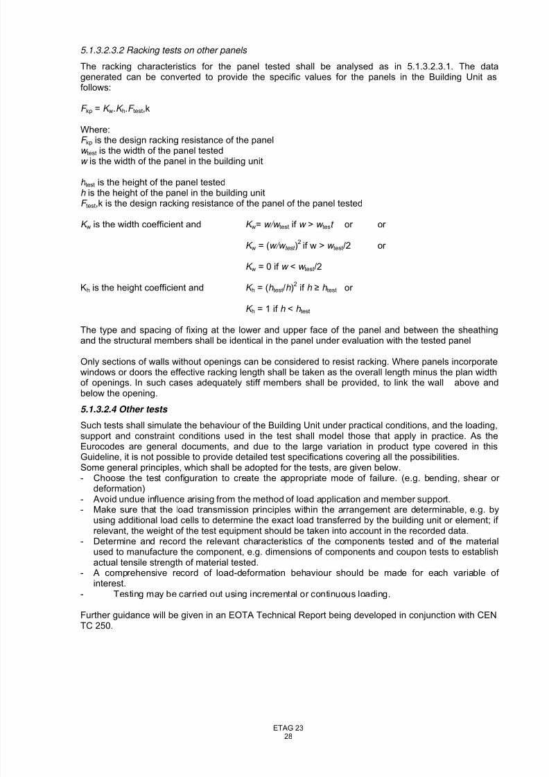
5.1.3.2.3.2 Racking tests on other panels
The racking characteristics for the panel tested shall be analysed as in 5.1.3.2.3.1. The datagenerated can be converted to provide the specific values for the panels in the Building Unit asfollows:
F kp = K w.K h.F test,k
Where:F kp is the design racking resistance of the panelw test is the width of the panel testedw is the width of the panel in the building unit
h test is the height of the panel testedh is the height of the panel in the building unitF test,k is the design racking resistance of the panel of the panel tested
K w is the width coefficient and K w= w/w test if w > w test or or
K w = (w/w test )2if w > w test/2 or
K w
= 0 if w < w test
/2
Kh is the height coefficient and K h = (h test/h )2
if h ≥ h test or
K h = 1 if h < h test
The type and spacing of fixing at the lower and upper face of the panel and between the sheathingand the structural members shall be identical in the panel under evaluation with the tested panel
Only sections of walls without openings can be considered to resist racking. Where panels incorporatewindows or doors the effective racking length shall be taken as the overall length minus the plan widthof openings. In such cases adequately stiff members shall be provided, to link the wall above andbelow the opening.
5.1.3.2.4 Other tests
Such tests shall simulate the behaviour of the Building Unit under practical conditions, and the loading,support and constraint conditions used in the test shall model those that apply in practice. As theEurocodes are general documents, and due to the large variation in product type covered in thisGuideline, it is not possible to provide detailed test specifications covering all the possibilities.Some general principles, which shall be adopted for the tests, are given below.- Choose the test configuration to create the appropriate mode of failure. (e.g. bending, shear or
deformation)- Avoid undue influence arising from the method of load application and member support.- Make sure that the load transmission principles within the arrangement are determinable, e.g. by
using additional load cells to determine the exact load transferred by the building unit or element; if relevant, the weight of the test equipment should be taken into account in the recorded data.
- Determine and record the relevant characteristics of the components tested and of the materialused to manufacture the component, e.g. dimensions of components and coupon tests to establishactual tensile strength of material tested.
- A comprehensive record of load-deformation behaviour should be made for each variable of interest.
- Testing may be carried out using incremental or continuous loading.
Further guidance will be given in an EOTA Technical Report being developed in conjunction with CENTC 250.
8/14/2019 ETAG023-Draft etag-06.11.23
http://slidepdf.com/reader/full/etag023-draft-etag-061123 29/73
ETAG 2329
5.2 Safety in case of fire
5.2.1 Reaction to fire
5.2.1.1 General
It should be noted that in some Member States (e.g. Germany) minimum requirements exist for thereaction to fire behaviour of all construction products. For Building Units this means that, where theproduct is to be used in a Member State having such requirements, a classification shall be given for all the materials used, from test data related to the product/material in end use conditions. However,the product need only be tested and classified in accordance with these rules when its use is intendedin those Member States where requirements exist. The Approval Body should agree with the ETAapplicant what testing will be required to suit the market. Certain small components are exempted fromreaction to fire requirements and current EOTA (PT4) guidance should be followed.
In some Member States requirements may exist to demonstrate the behaviour of products with respectto continuous glowing combustion in case of fire. The mandates for the product standards, therefore,are currently under revision. Additional national assessment e.g. on the basis of national procedures todemonstrate this behaviour might be required until a European harmonised procedure is available.
For façades a European fire scenario has not been laid down. This may be a factor in the assessmentof some types of Building Units. An additional assessment according to national provisions (e.g. on thebasis of examining design solutions or a large scale test) might be necessary to comply with Member State regulations until the existing European classification system has been completed.
Due to the complexity of Building Units, several approaches may need to be combined in order todetermine reaction to fire characteristics, using harmonised classification:
5.2.1.2 Testing
Individual components, as part of an assembly, as appropriate, shall be tested, using the testmethod(s) relevant for the corresponding reaction to fire class, in order to be classified according toEN 13501-1:2002. Where individual components are covered by harmonised product standards,
reference can be made to these for guidance on mounting and fixing provisions. The followingparagraphs provide further guidance for some components.
5.2.1.2.1 COMPOSITE PANELS
Testing of composite panels, with respect to reaction to fire shall be undertaken as described in :
- For metal faced sandwich panels: prEN 14509- For other composite panels: ETA-Guideline 016- For floor panels: Although not part of the scope of the technical specifications covered by
the above two bullet points, floor panels should be assessed in accordance with those
documents. In addition, the provisions of clause 5.2.2.1.2 apply.
5.2.1.2.2 Additional information regarding the determination of the burning behaviour using a radiant heat source
This test method is only required for floor panels and their coverings (if any). It shall beperformed in accordance with EN ISO 9239-1, unless modified below.
5.2.1.2.2.1 Number of test specimen (EN ISO 9239-1, clause 5)
Where the ETA covers more than one floor covering, the test will need to be repeated for eachtype of floor covering but not necessarily each colour option, provided it can be establishedthat the colour and/or type of pigment do not affect the result.
8/14/2019 ETAG023-Draft etag-06.11.23
http://slidepdf.com/reader/full/etag023-draft-etag-061123 30/73
ETAG 2330
5.2.1.2.2.2 Test specimen (EN ISO 9239-1, clauses 5.2, 5.3 and 5.4)
In accordance with the note in clause 5.2, the length of the specimen shall be reduced to1025 ± 5 mm, unless the test is performed on the floor covering alone.The test specimen consists of the floor panel and the floor covering (if any), using theadhesive specified by the ETA-applicant (if any). The test specimen shall be secured to thesubstrate by mechanical means. The test substrate shall be in accordance with clause 5.1 of
EN 13238.No durability assessment is foreseen in connection with this characteristic.
Note: Guidance is under development in GNB-SH02 and should be used by Approval Bodies when approved.
5.2.1.2.2.3 Conditioning (EN ISO 9239-1, clauses 5.4 and 6)
The curing time of the adhesive is in accordance with the ETA-applicant’s specifications.
5.2.1.2.2.4 Test report (EN ISO 9239-1, clause 9)
In addition to the requirements of EN ISO 9239-1, the test report shall be in accordance with ECGuidance paper K.
5.2.1.3 Classification as Class A1
Individual components of the Unit are considered to satisfy the requirements for performance Class A1of the characteristic reaction to fire, in accordance with the provisions of EC Decision 96/603/EC (asamended) without the need for testing on the basis of its listing in that Decision.
5.2.1.4 Classification without further testing
Products classified without the need for further testing (CWFT). Individual components, [asappropriate] are considered to satisfy the requirements for a performance Class of the characteristic
reaction to fire in accordance with an EC Decision without the need for testing on the basis of itsconformity with the specification of the product detailed in that Decision and its intended end useapplication being covered by that Decision. This option may only be used if relevant and once asuccessful case for its use has been made to the EC Expert Group -Fire, endorsed by the SCC.
5.2.2 Resistance to fire
The complete Building Unit or, where relevant, its components in an assembly representing end useconditions, shall be tested, using the test method relevant for the corresponding fire resistance class,in order to be classified according to the appropriate Part of EN 13501. Determination of theloadbearing capacity of the units, when exposed to fire, may also be undertaken by calculationaccording to, or tabulated values in, relevant Eurocodes.
When testing sandwich panel assemblies, conventional thermocouples shall be used for the first fiveminutes of all fire resistance tests and then a transition to plate thermometer control shall be made(see EN 1363-1, 5.1.2 – Note).
Note:
Ideally, a smooth transition should be made taking a maximum of five minutes before full control by plate thermometers. If the furnace control system does not allow this, then a sudden transition can be made. With care, if both control systems are set to follow the time temperature curve specified in EN 1363-1, the resulting time-temperature curve, as measured by the plate thermometers, should be within the tolerances allowed by EN 1363-1.
5.2.3 External fire performance of the roof covering
The external fire performance of any roof covering included in the Building Unit shall be verified usingthe appropriate method from the following:
8/14/2019 ETAG023-Draft etag-06.11.23
http://slidepdf.com/reader/full/etag023-draft-etag-061123 31/73
ETAG 2331
- The component, or the assembled system of which the component may form part of, shall be testedusing the test method relevant for the corresponding external fire performance roof class, in order tobe classified according to EN 13501-5- The component, or the assembled system of which the component may form part of, is considered tosatisfy all the provisions for external fire performance of all national regulations of the Member Stateswithout the need for testing on the basis that it is included within the definitions given in CommissionDecision 2000/553/EC and provided that any national provisions on the design and execution of worksare fulfilled. In this case, the Approval body shall verify product compliance with the definitions of thedecision.- The component, or the assembled system of which the component may form part of, is consideredto satisfy the requirements for performance class of the characteristic external fire performance inaccordance with an EC Decision published in the OJEC without the need for testing on the basis of itsconformity with the specification of the product detailed in that EC Decision and its intended end useapplication being covered by that EC Decision. In this case, the Approval body shall verify productcompliance with the definitions of the decision.
5.2.4 Fire compartmentation
Fire compartmentation of a building is a function of its application and the regulations for Works inforce in the Member State where the building is to be built (see boxed wording in the Foreword to thisETAG). The ETA shall give details of the reaction to fire and resistance to fire of elements of theBuilding Unit, such as internal walls. It is for the designer of the Works to determine their suitability and
their position for particular buildings.
5.3 Hygiene, health and environment
5.3.1 Vapour permeability and moisture resistance
Assessment shall be undertaken on the basis of calculations according to EN ISO 13788, taking intoaccount the relevant design climatic conditions. This standard includes information on the assessmentof the risk of mould growth.
The risk of condensation can normally be verified on the basis of hygrothermal characteristics of theproducts used in each component and the construction details.
Water vapour resistance of the relevant layers should be based upon:
Design values given in EN 12524 or European technical specificationsor
Tests according to EN ISO 12572 or European technical specifications
It should be noted that the permeability of some materials can vary dependent on whether they arewetting-up(absorption) or drying-down (desorption) in a particular environment (hysteresis effects).This should be considered, particularly when using design values. This is described in EN ISO 125727.1 Test conditions, Note 1 and has to be taken into consideration when calculations are made.
In addition, the design of joints and any fixings/services penetrating any vapour control element or
membrane shall be assessed in relation to the risk of airborne moisture coming into contact with coldsurfaces within the construction.
It should be further noted that some Member States have prescriptive requirements for the relativehumidity in buildings and in building elements (although it may be possible for other values to beaccepted, based on an analysis of the system). This should be investigated by the Approval Body andthe ETA applicant, in relation to the intended market.
5.3.2 Watertightness
5.3.2.1 External envelope
Water leakage resistance of the building envelope, including driving rain on facades and possiblysnow penetration, shall primarily be assessed by the Approval Body on the basis of the standardconstruction details for the Building Unit, and by using the available technical knowledge andexperience from similar well-known technical solutions. The assessment shall include the full external
8/14/2019 ETAG023-Draft etag-06.11.23
http://slidepdf.com/reader/full/etag023-draft-etag-061123 32/73
ETAG 2332
envelope, including joints within Units, joints between the Units and joints between the Unit and thesubstructure, where the latter are intended to provide weathertightness.
If the resistance against the effects of weather cannot be assessed by the use of existingknowledge, e.g. because of unfamiliar solutions to the relevant construction details, the Approval Bodymay find it necessary to require testing of the external envelope performance. Laboratory tests may becarried out according to EN 1027(Doors and Windows), EN 12865 (Walls) or ETAG 016.
Dependent upon the design of the Unit, it may be necessary to consider the watertightness of theenvelope before the final outer layer e.g. a brick skin, is added. Temporary provisions may beincorporated at the factory or the ETA applicant will make recommendations for on-site provisions. Itwill not normally be necessary to undertake tests, as the requirement for watertightness is normallyshort-term. However, the Approval Body shall ensure that in the period before final completion of theexternal envelope, the risk of damage to the structure and/or to internal finishes will be minimised,taking account of the possible effects of driving rain and strong winds on vulnerable materials.
5.3.2.2 Internal surfaces and membranes
The performance of watertight membranes, or surface layers in wet areas such as bathrooms, may beassessed on the basis of experience/technical knowledge. Alternatively, it may be verified byreference to conformity with relevant performance standards for the products involved, e.g. productstandards for roofing membrane systems. For products with unknown performance, verification can be
according to the Nordtest methods NT BUILD 058, 230 and 448 and/or ETAG 022 (Watertightcoverings for bathrooms).The primary purpose of the membrane is to ensure that the construction does not attain a moisturecontent such that damage, particularly in relation to durability, could occur.It should be noted that some Member States have prescriptive requirements for the vapour permeability of these membranes (although it may be possible for more permeable membranes to beaccepted, based on an analysis of the system). This should be investigated by the Approval Body andthe ETA applicant, in relation to the intended market.
5.3.3 Release of dangerous substances
5.3.3.1 Presence of dangerous substances in the product
The applicant shall submit a written declaration stating whether or not the product contains dangeroussubstances according to European and national regulations, when and where relevant in the Member States of destination, and shall list these substances.
5.3.3.2 Compliance with the applicable regulations
If the product contains dangerous substances as declared above, the ETA will provide the method(s)which has been used for demonstrating compliance with the applicable regulations in the Member States of destination, according to the dated EU data-base (method(s) of content or release, asappropriate).
5.3.3.3 Application of the precautionary principle
An EOTA member has the possibility to provide to the other members, through the Secretary General,warning about substances which, according to Health authorities of its country, are considered to bedangerous under sound scientific evidence, but are not yet regulated. Complete references about thisevidence will be provided.This information once agreed upon, will be kept in an EOTA data base, and will be transferred to theCommission services.The information contained in this EOTA database will also be communicated to any ETA applicant.On the basis of this information, a protocol of assessment of the product, regarding this substance,could be established on request of a manufacturer with the participation of the Approval Body thatraised the issue.
5.4 Safety in use
5.4.1 Slipperiness of floor finishes
Verification of slip resistance of flooring materials shall be undertaken in accordance with the relevantEN-standards for the specified finished flooring products.
8/14/2019 ETAG023-Draft etag-06.11.23
http://slidepdf.com/reader/full/etag023-draft-etag-061123 33/73
ETAG 2333
5.4.2 Falling due to sudden changes in level or sudden drops
The Approval Body shall assess the design and shall give the dimensions of any unprotected changesin floor level in the ETA. This shall include any discontinuities that might arise from coupling unitstogether. Where the Unit includes stairs, guard rails, balustrades etc at openings, if not alreadycovered by CE marking, these shall be assessed as part of the Unit. Reference can be made to ETAG008 for Stair Kits and to relevant EN standards for other components/systems. When suchcomponents are assessed only as part of the Unit, subsequent CE marking of the component itself isnot permissible.
5.4.3 Resistance to eccentric loads, including impact resistance.
Mechanical resistance against dynamic loads shall primarily be assessed by the Approval Body on thebasis of existing knowledge related to the intended use. Walls with well-known internal lining materials,such as standard gypsum boards, wood-based panel products and solid timber boards with studs,should generally be accepted to have a satisfactory impact resistance for normal use in, for example,dwellings and office buildings.
When the performance is not known to be acceptable, or a quantified performance is to be declareddue to national building regulations in some member states, the impact resistance should be tested.Testing of walls is to be carried out in accordance with EOTA Technical Report TR001.
Roofs and timber floors can be tested according to EN 1195.
For wood-based panels used as loadbearing sub-floor panels on joists and as roof sheathing theimpact resistance should be accepted as adequate when the panels conform to the requirements inprEN 12871.
Where an approach is described in a relevant Eurocode, it will be acceptable to calculate impactresistance using this method.
Assessment of resistance to structural damage from eccentric load from fixtures shall be carried outfollowing testing in accordance with the relevant sections of Chapter 5.4 of ETAG 003.
5.5 Protection against noise
5.5.1 Airborne sound insulation
The airborne sound insulation performance (between rooms, of facades and of roofs, dependent onregulatory provisions in the destination Member State) of the main building parts of an assembly of Units shall be verified by either laboratory or field tests according to the relevant parts of EN ISO 140-3, -10 or -12 (laboratory tests) and -4 or -5 (field tests). The rating of airborne sound insulation shall beundertaken according to EN ISO 717-1.Estimated values for airborne sound insulation in completed buildings, based on laboratory tests, canbe determined according to EN 12354-1, -3 or -4.Indicative field testing of an assembly within a manufacturer’s range may be possible, as part of theApproval process. However, National Regulations in some Member States may require field testing of
the completed building in each case.
5.5.2 Impact sound insulation
The impact sound insulation performance of the floors of an assembly of Units shall be verified byeither laboratory or field tests according to the relevant parts of EN ISO 140-6, -8, -9, -10, -11 or -12(laboratory tests) and -7 (field tests), and the rating of impact sound insulation shall be undertakenaccording to EN ISO 717-2.Estimated values for impact noise level in completed buildings, based on laboratory tests, shall bedetermined according to EN 12354-2.Indicative field testing of an assembly within a manufacturer’s range may be possible, as part of theApproval process. However, National Regulations in some Member States may require field testing of
the completed building in each case.
8/14/2019 ETAG023-Draft etag-06.11.23
http://slidepdf.com/reader/full/etag023-draft-etag-061123 34/73
ETAG 2334
5.5.3 Sound absorption
Sound absorption shall be measured according to EN ISO 354.Estimated values for sound absorption in an assembly of Units, based on laboratory tests, shall bedetermined according to prEN 12354-6.
5.6 Energy economy and heat retention
5.6.1 Thermal resistance Thermal resistance (R-value) and the corresponding thermal transmittance (U-value) of the relevantparts (eg external walls) shall be calculated according to EN ISO 6946, using the declared thermalconductivity values given in the CE marking for materials, if possible according to the variousharmonised specifications.
If CE marking is not possible, the thermal conductivity values can be obtained from:
− Thermal conductivity values tabulated in EN 12524 for general building materials
− Declared thermal conductivity values determined according to EN ISO 10456
− Declared values obtained from non-harmonised European standards.
Declared values from non-harmonised standards and prescribed values should be treated with somecaution. For example the moisture content of materials can affect the thermal conductivity. Whennecessary, the declared thermal conductivity value can be corrected due to moisture content, ageingand temperature of the different materials resulting from work conditions, according to the method inEN ISO 10456 (chapter 6). See also paragraph 5.3.1
Verification of thermal transmittance for windows, doors and shutters may be undertaken bycalculation according to EN ISO 10077-1, prEN ISO 10077-2 or by testing according to relevantEN/ISO-standards for these products.
If the design incorporates significant thermal bridges, not covered by the normal verification of the
thermal resistance as mentioned above, the effect on the overall thermal resistance and the surfacetemperatures in relation to 4.3.1 shall be verified. In particular, the possible effect of the moisture dueto condensation at these thermal bridges shall be examined. Such verification may be undertaken bycalculations according to EN ISO 10211-1 and EN ISO 10211-2, or by testing according to EN ISO8990 or relevant test standards for specific products.
5.6.2 Air permeability
Assessment of the air permeability of the external envelope is normally undertaken by judgement of the construction details, on the basis of the knowledge and experience from traditional technicalsolutions. The assessment shall include joints between components in a Building Unit and, if relevant, joints between one Unit and another.
When the Approval Body finds it necessary, e.g. when non-traditional joints are used, the air permeability shall be verified by testing. Tests may be carried out by pressurisation of completedbuildings according to EN 13829, or by laboratory testing according to EN 1026, EN 12114 or other relevant test standards. Consideration shall be given to long-term performance, when relevant (e.g.when joints incorporate tape or sealants).
The assessment of air permeability should be undertaken both with regard to energy economy(unintentional ventilation), cold draughts (see 4.6.2) and the risk of water vapour condensation insidethe construction (see 4.3.1) due to inadequate ventilation. The assessment shall be undertaken on thebasis of the intended use of the Building Unit, taking into account the internal and external designclimates (e.g. geographical areas).
5.6.3.Thermal inertia
Verification of the thermal inertia of assembled buildings is undertaken in accordance with EN 832 onthe basis of the following properties of the relevant building components which the Approval Bodyshall verify:- the total mass per unit area (determined in accordance in the framework of identification)
8/14/2019 ETAG023-Draft etag-06.11.23
http://slidepdf.com/reader/full/etag023-draft-etag-061123 35/73
ETAG 2335
- density (determined in accordance in the framework of identification or EN 1991-1-1, Annex A)- specific heat capacity (determined in accordance with EN 12524 or appropriate product standards)- thermal resistance (determined in the framework of ER6).
5.7 Durability, serviceability and identification
5.7.1 Durability – General
The product specification shall be examined and tests carried out where necessary, to ensure theproduct durability is appropriate for the intended use. It is necessary to consider the PrefabricatedBuilding Unit in relation to its individual components and materials as well as its behaviour as anassembly (compatibility of components/materials). Durability shall be considered in relation to eachregulated requirement.
The estimated working life of the various materials and components of the Unit shall be determined bythe Approval Body, mainly by examining the specification against the requirements of relevant standardsetc and on the basis of experience and general knowledge. Due account shall be taken of ease, and thecost implications, of replacement of the component when the Unit is incorporated into a building. It is notnormally acceptable for major structural components to require replacement within the envisaged
working life of the building.
References and other information, in the following paragraphs, relate to materials and componentscommonly used in Building Units. Where materials are used that are not covered by these standards or where the manufacturer makes specific performance claims, the Approval Body may make use of documented evidence of performance, existing approvals or compliance with relevant European or other standards or European Technical Approvals. Where products are used that already bear CE marking,due account shall be taken of any use categories or other limitations embodied in such marking.
5.7.1.1 Panels
The durability of sandwich panels shall be determined in accordance with:- For metal faced sandwich panels: prEN 14509
- For other sandwich panels: ETA-Guideline 016 and/or ETA-Guideline 019- For floor panels and supporting profiles: Although not part of the scope of the above
mentioned technical specifications, these components can be assessed in accordance with
these documents.
5.7.1.2 Sealants
Sealants may be classified in accordance with ISO 11600. Their durability shall be determinedin accordance with ISO 10590 (adhesion / cohesion properties at maintained extension after immersion in water) and ISO 11431 (adhesion / cohesion properties after exposure to heatand artificial light).
5.7.1.3 Gasket and weatherstripping
Gaskets and weatherstripping shall be classified in accordance with EN 12365-1. On the basis
of the determined classification, an assessment can be made of the suitability of the gasket inthe proposed application.
5.7.1.4 Windows and doors
Windows and doors that form part of the Building Unit, and are not already covered by CEmarking, may be tested and assessed by reference to pr EN14351.
5.7.1.5 Rainwater goods
Gutter systems/components in PVC-U and sheet metal may be assessed by reference to EN607, EN1462, prEN 12200 and EN612.
5.7.1.6 Miscellaneous materials
The following materials may be encountered in the construction of Building Units :
8/14/2019 ETAG023-Draft etag-06.11.23
http://slidepdf.com/reader/full/etag023-draft-etag-061123 36/73
ETAG 2336
5.7.1.6.1 Painted steel
The adequacy of a coating on steel can be assessed by reference to EN ISO 12944 in its variousparts.
5.7.1.6.2 Coil coated aluminium
Coil coated aluminium can be assessed against EN 1396.
5.7.1.6.3 Galvanised or aluminium coated steel
The adequacy of this type of corrosion protection can be assessed by reference to EN ISO14713, which gives general recommendations on corrosion protection.
5.7.1.6.4 Coil coated steel
Coil coated steel can be assessed by reference to EN 10169.
5.7.1.6.5 Stainless steel
Stainless steels are classified by reference to EN 10088. Annex B of EN 10088 containsgeneral guidance on the use of stainless steels including the aspect of corrosion resistance.
Ferritic stainless steels have relatively low corrosion resistance and their use should normallybe restricted to mild indoor or similarly protected environments.Austenitic stainless steel: The most common alloys are 1.4301 (X5CrNi18-10) and 1.4401(X5CrNiMo17-12-2). These austenitic stainless steels are normally suitable for use in all usecategories. However, where high chloride contents or more severe conditions are likely to bepresent in the environment (e.g. rooms with indoor swimming pools, facades in cities withheavy traffic, in coastal areas), alloys with higher molybdenum content, e.g. 1.4429(X2CrNiMoN17-13-3), 1.4539 (X1NiCrMoCu25-20-5) or 1.4529 (X1NiCrMoCuN25-20-7), arerecommended.Austentic-ferritic steels, e.g. 1.4462 (X2CrNiMoN22-5-3), are comparable to a CrNiMo-steelwith 2,5 to 3% Mo.
5.7.1.6.6 Thermoplastic polymeric materials
Extruded profiles in PVC-U shall be designated and assessed for suitability using EN 13245-1or 3 and the associated tests in EN 13245-2. These standards allow a distinction to madebetween profiles that are to be externally exposed and those that are for internal use only.In determining suitability of a profile in a particular application the Approval Body shall take dueaccount of the consequences of failure, in particular related to the costs of access and theassociated dismantling of the building.
For injection moulded components, the effects of heating can be determined, as a measure of quality, using the method described in EN 763, on 3 samples selected from each of 5production batches.After conditioning, no weld line shall have opened completely and no cracks or delaminationshall penetrate more than 50 % of the thickness, at the point of injection. If 1 of any 3 samplesexhibits a failure a retest may be undertaken on 6 further components. If any of these samplesfails the product shall be deemed unacceptable.
5.7.1.6.7 GRP (Glass reinforced plastic) faced panels
Where GRP is used, for example as a face for composite panels in Prefabricated Building Units, in theabsence of standardised methods, its durability can be assessed by undertaking the following tests todetermine how moisture might affect the long-term bond strength of the composite:
− Effects of boiling in water. An accelerated ageing test shall be undertaken by boiling asample of the panel in water, followed by tensile strength tests perpendicular to the faces.The samples shall correspond to the provisions of EN 1607. The sample shall be boiled for a period of (120 ± 10) min. The tensile strength, perpendicular to the faces, in accordance
with EN 1607, shall be determined before and after this accelerated ageing.
− Effects of condensation. Samples shall be exposed to condensation by assembling thepanel samples above a heated water bath, followed by a tensile strength tests

8/14/2019 ETAG023-Draft etag-06.11.23
http://slidepdf.com/reader/full/etag023-draft-etag-061123 37/73
ETAG 2337
perpendicular to the faces. The samples shall correspond to the provisions of EN 1607.The temperature of the water shall be (65 ± 2) °C and the exposure period is (35 ± 1)days. The tensile strength, perpendicular to the faces, in accordance with EN 1607, shallbe determined before and after this accelerated ageing.
It is for the Approval Body to judge the significance of the results of the above tests, based on the waythe GRP faced composite panel is used in the Building Unit, for example its contribution to structuralstrength.
5.7.1.6.8 Wood
The adequacy of wood components in can be judged by reference to EN 350-1 and-2 and EN 335-1 -2and -3.
5.7.1.6.9 Concrete and concrete products
Durability of concrete and concrete products can be judged by reference to Eurocode 2, EN 206, EN13369 and the related product-specific standards. See Annex B for a list of possibly relevant Standards.
5.7.1.6.10 Facing materials – render, brick, stone etc
Where a facing material is known to be or is suspected of being sensitive to hygrothermal variations
e.g. factory applied render, brick slips or stone, the tests described in ETAG 017 shall be applied. TheApproval Body shall determine a suitable test sample to best represent the facing as applied to theBuilding Unit.
5.7.1.7 Component and materials compatibility
The Approval Body shall examine the design of the Building Unit and make an assessment, using well-established principles, of the suitability of materials in contact. It is impossible to prescribe all thepossible risk areas but these include the possibility of bi-metallic corrosion, the effects of woodpreservatives on metals or plastics and the effects of solvent based coatings on the impact strength of plastics.
5.7.2 Aspects of serviceability
Deflection of the loadbearing elements is covered in clause 5.1. The stiffness of suspended floor structures shall be calculated in accordance with the relevant Eurocode to check adequateserviceability under normal traffic loads.
In assessing the structural strength and stiffness of the Units, in 5.1, it will be necessary to ensure thatthey can withstand the additional stresses imposed during the transport and installation process. Inmaking this assessment it is to be assumed that the Units will only be lifted in accordance with theETA applicants instructions using, for example, the lifting points provided.
Where Units are claimed to be re-locatable, this shall also be taken into account in assessingstructural adequacy although it can be assumed that buildings will be subjected to a structuralcondition survey before dismantling and re-location. This is particularly relevant where re-location is totake place late in the design life of the Units.
5.7.3 Identification
All components of the Building Unit shall be identified, either by reference to:- Harmonised product standards- European Technical Approvals, based on other ETA-Guidelines and CUAP’s- Non-harmonised European product standards- Non-harmonised International product standards- Descriptive identification, identifying the products by their composing materials and their function
In any case, dimensions (length, width, thickness), geometry (squareness, flatness, …), significantproperties (mechanical, physical, chemical, …) and their tolerances shall be given. In those caseswhere the above listed product specifications do not specify test methods for identification, test
methods used should be based on European standards (CEN), International standards (ISO), EOTATechnical Reports, UEAtc Guidelines, Nordtest standards or RILEM test methods.Ultimately, a formulation, an ETA applicant’s specific reference or a similar unique specification canalso be accepted.
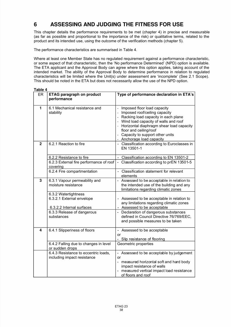
8/14/2019 ETAG023-Draft etag-06.11.23
http://slidepdf.com/reader/full/etag023-draft-etag-061123 38/73
ETAG 2338
6 ASSESSING AND JUDGING THE FITNESS FOR USE
This chapter details the performance requirements to be met (chapter 4) in precise and measurable(as far as possible and proportional to the importance of the risk) or qualitative terms, related to theproduct and its intended use, using the outcome of the verification methods (chapter 5).
The performance characteristics are summarised in Table 4.
Where at least one Member State has no regulated requirement against a performance characteristic,or some aspect of that characteristic, then the ‘No performance Determined’ (NPD) option is available.The ETA applicant and the Approval Body can agree where this option applies, taking account of theintended market. The ability of the Approval Body to determine performance in relation to regulatedcharacteristics will be limited where the Unit(s) under assessment are ‘incomplete’ (See 2.1 Scope).This should be noted in the ETA but does not necessarily allow the use of the NPD option.
Table 4
ER ETAG paragraph on productperformance
Type of performance declaration in ETA’s
1 6.1 Mechanical resistance and
stability
- Imposed floor load capacity
- Imposed roof/ceiling capacity- Racking load capacity in each plane- Wind load capacity of walls and roof - Horizontal diaphragm shear load capacity
floor and ceiling/roof - Capacity to support other units- Anchorage load capacity
2 6.2.1 Reaction to fire - Classification according to Euroclasses inEN 13501-1
6.2.2 Resistance to fire - Classification according to EN 13501-2
6.2.3 External fire performance of roof covering
- Classification according to prEN 13501-5
6.2.4 Fire compartmentation - Classification statement for relevantelements
3 6.3.1 Vapour permeability andmoisture resistance
- Assessed to be acceptable in relation tothe intended use of the building and anylimitations regarding climatic zones
6.3.2 Watertightness6.3.2.1 External envelope - Assessed to be acceptable in relation to
any limitations regarding climatic zones6.3.2.2 Internal surfaces - Assessed to be acceptable
6.3.3 Release of dangeroussubstances
- Declaration of dangerous substancesdefined in Council Directive 76/769/EEC,and possible measures to be taken
4 6.4.1 Slipperiness of floors - Assessed to be acceptableor - Slip resistance of flooring
6.4.2 Falling due to changes in levelor sudden drops
Geometric properties
6.4.3 Resistance to eccentric loads,including impact resistance
- Assessed to be acceptable by judgementor - measured horizontal soft and hard body
impact resistance of walls- measured vertical impact load resistance
of floors and roof
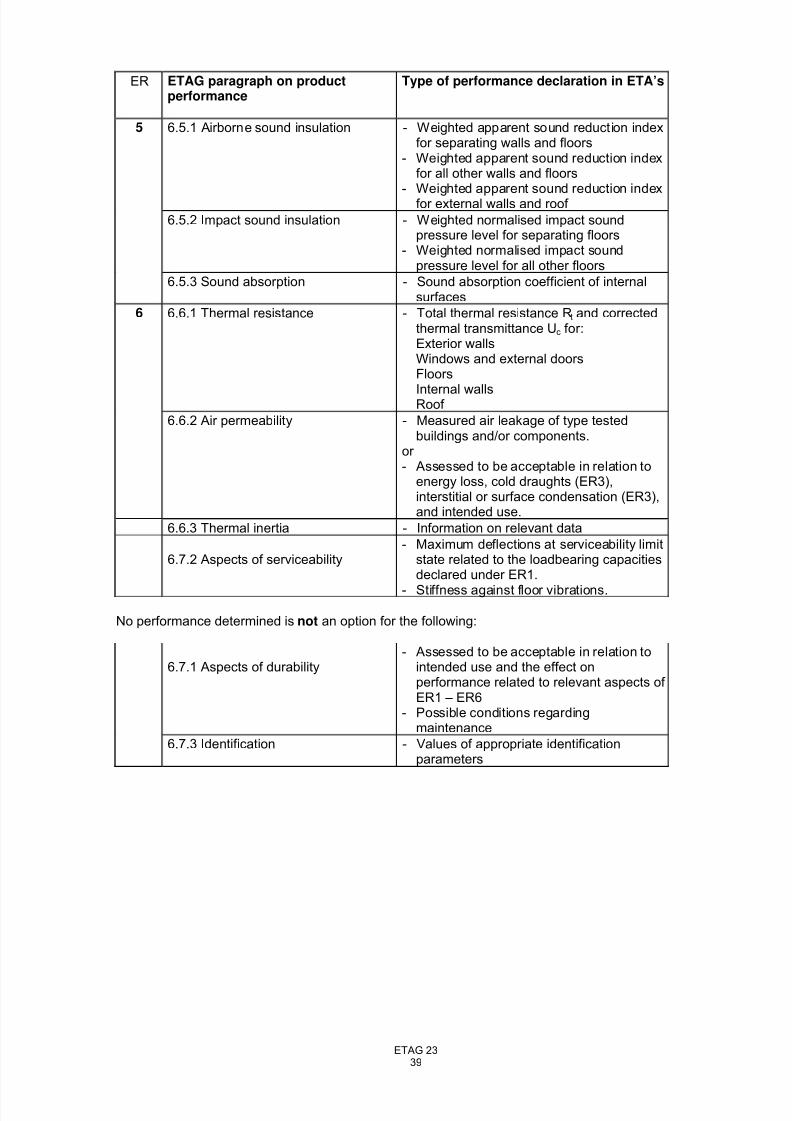
8/14/2019 ETAG023-Draft etag-06.11.23
http://slidepdf.com/reader/full/etag023-draft-etag-061123 39/73
ETAG 2339
ER ETAG paragraph on productperformance
Type of performance declaration in ETA’s
5 6.5.1 Airborne sound insulation - Weighted apparent sound reduction indexfor separating walls and floors
- Weighted apparent sound reduction indexfor all other walls and floors
- Weighted apparent sound reduction indexfor external walls and roof
6.5.2 Impact sound insulation - Weighted normalised impact soundpressure level for separating floors
- Weighted normalised impact soundpressure level for all other floors
6.5.3 Sound absorption - Sound absorption coefficient of internalsurfaces
6 6.6.1 Thermal resistance - Total thermal resistance Rt and correctedthermal transmittance Uc for:Exterior wallsWindows and external doorsFloors
Internal wallsRoof
6.6.2 Air permeability - Measured air leakage of type testedbuildings and/or components.
or - Assessed to be acceptable in relation to
energy loss, cold draughts (ER3),interstitial or surface condensation (ER3),and intended use.
6.6.3 Thermal inertia - Information on relevant data
6.7.2 Aspects of serviceability- Maximum deflections at serviceability limit
state related to the loadbearing capacitiesdeclared under ER1.
- Stiffness against floor vibrations.
No performance determined is not an option for the following:
6.7.1 Aspects of durability- Assessed to be acceptable in relation to
intended use and the effect onperformance related to relevant aspects of ER1 – ER6
- Possible conditions regardingmaintenance
6.7.3 Identification - Values of appropriate identificationparameters
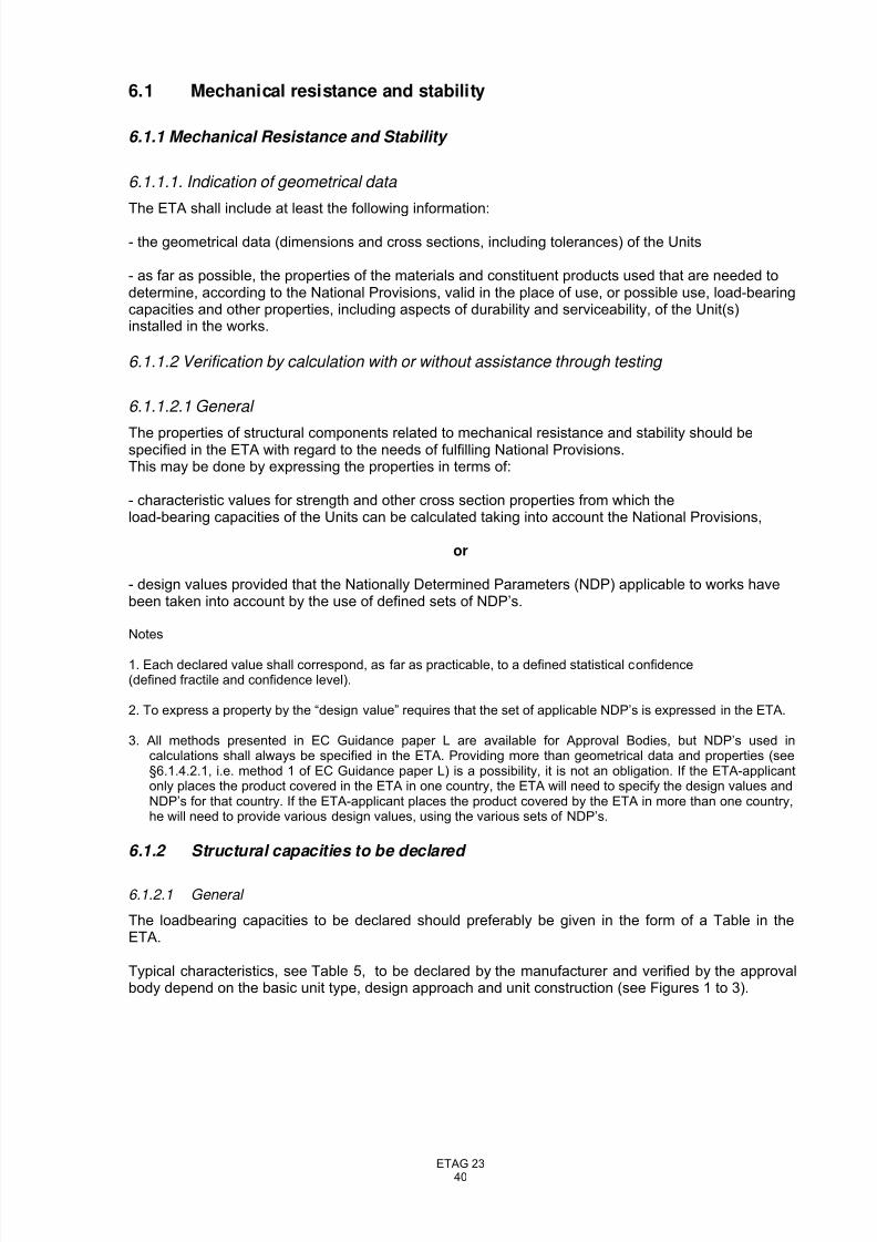
8/14/2019 ETAG023-Draft etag-06.11.23
http://slidepdf.com/reader/full/etag023-draft-etag-061123 40/73
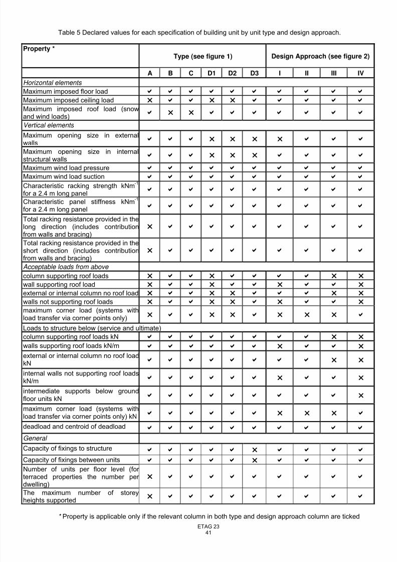
8/14/2019 ETAG023-Draft etag-06.11.23
http://slidepdf.com/reader/full/etag023-draft-etag-061123 41/73
ETAG 2341
Table 5 Declared values for each specification of building unit by unit type and design approach.
Property *Type (see figure 1) Design Approach (see figure 2)
A B C D1 D2 D3 I II III IV
Horizontal elements
Maximum imposed floor load b b b b b b b b b bMaximum imposed ceiling load r b b r r b b b b bMaximum imposed roof load (snowand wind loads) b r r b b b b b b b
Vertical elements
Maximum opening size in externalwalls b b b r r r r b b b
Maximum opening size in internalstructural walls b b b r r r b b b b
Maximum wind load pressure b b b b b b b b b bMaximum wind load suction b b b b b b b b b bCharacteristic racking strength kNm
-1
for a 2.4 m long panel
b b b b b b b b b b
Characteristic panel stiffness kNm-1
for a 2.4 m long panel b b b b b b b b b b
Total racking resistance provided in thelong direction (includes contributionfrom walls and bracing)
r b b b b b b b b b
Total racking resistance provided in theshort direction (includes contributionfrom walls and bracing)
r b b b b b b b b b
Acceptable loads from above
column supporting roof loads r b b r b b b b r r
wall supporting roof load r b b r b b r b b r
external or internal column no roof loadr
b b r r b b b r rwalls not supporting roof loads r b b r r b r b b r
maximum corner load (systems withload transfer via corner points only) r b b r r b r r r b
Loads to structure below (service and ultimate)
column supporting roof loads kN b b b b b b b b r r
walls supporting roof loads kN/m b b b b b b r b b r
external or internal column no roof loadkN b b b b b b b b r r
internal walls not supporting roof loadskN/m b b b b b b r b b r
intermediate supports below groundfloor units kN b b b b b b b b b r
maximum corner load (systems withload transfer via corner points only) kN b b b b b b r r r b
deadload and centroid of deadloadb b b b b b b b b b
General
Capacity of fixings to structureb b b b b r b b b b
Capacity of fixings between units b b b b b r b b b bNumber of units per floor level (for terraced properties the number per dwelling)
r b b b b b b b b b
The maximum number of storeyheights supported r b b b b b b b b b
* Property is applicable only if the relevant column in both type and design approach column are ticked
8/14/2019 ETAG023-Draft etag-06.11.23
http://slidepdf.com/reader/full/etag023-draft-etag-061123 42/73
ETAG 2342
6.1.2.2 Specific notes regarding declared resistances
6.1.2.2.1
The load-carrying capacity of floors and of roof structures with specified maximum spans shallnormally be given as net imposed load resistances, and net design snow load and/or wind loadresistance as defined in EN 1991-2-3 and EN 1991-2-4. (The effect of the self-weight of the floor androof structure shall be taken into account in order to declare the net load capacity).When tested according to Annex C the characteristic value for deformation at service loads may be
calculated from measurements taken at several similar points on the tested Unit. This shall complywith the acceptance criteria given in 6.7.2.When tested according to Annex C the Units are considered to have satisfactory resistance to appliedloading if the unit withstands the maximum test load without collapsing.
6.1.2.2.2
The load-carrying capacity of walls shall be given for specified wall heights as vertical resistance andracking strength per unit length of the walls, and as horizontal design resistance perpendicular to thewall per unit area.
6.1.2.2.3
In all cases it will also be necessary to establish the adequacy of connections to ensure that they havea factor of safety in line with the requirements of the Eurocodes.
6.1.2.2.4
The methods for determining the characteristic performance of the Unit shall be specified and includethe requirements for the factory production control and for the conformity attestation of thecharacteristic values.
6.1.3 Resistance against seismic actions
Load-bearing capacities of the main building parts and anchorage, including racking resistance andhorizontal diaphragm shear load capacity, is covered by 6.1.2. If a Building Unit is to be put on themarket in areas with seismic zones, the masses of the building parts shall be declared, as well as thespecific characteristics of connections and factors for energy dissipation according to the methods of calculation given in 5.1.2.
6.1.4 Structural analysis
The detailed structural analysis to verify the declared capacities mentioned in 6.1.1 shall be availableto the Approved (Notified) Body as a part of the technical file for the ETA.
6.2 Safety in case of fire
6.2.1 Reaction to fire
The components/materials, as incorporated into the Building Units, shall be classified according to EN13501-1.
6.2.2 Resistance to fire
The Building Units shall be classified according to the appropriate Part of EN 13501.
6.2.3 External fire performance
The components, or the assembled system of which the component may form part of, shall beclassified according to EN 13501-5.
8/14/2019 ETAG023-Draft etag-06.11.23
http://slidepdf.com/reader/full/etag023-draft-etag-061123 43/73
ETAG 2343
6.2.4 Fire compartmentation
The ETA shall give details of the classification of elements, such as internal walls, so that the designer of the Works can make use of this data when seeking to meet the regulatory requirements in force inthe Member State in which the building is to be constructed.
6.3 Hygiene, health and environment
6.3.1 Vapour permeability and moisture resistance
The product specifications shall be examined and performance, in respect of exposure to moisture,assessed on the basis of known material properties, design details and the intended use.It shall be established that condensation in the structure as a result of water vapour diffusion will notoccur or will occur only to an extent where damage is not caused during the condensation period andthat the structure will dry out again during the evaporation period.
The assessment is to be undertaken with respect to both to interstitial and internal surfacecondensation.
The performance of the building is stated in the form of acceptable intended uses relevant to thedesign climatic conditions, e.g. types of buildings and geographical zones.
6.3.2 Watertightness
6.3.2.1 External envelope
The performance of the building will normally have to be declared in qualitative terms in relation to theintended use (potential climatic zones) and with respect to durability aspects (see EC Guidance Paper F on Durability and the Construction Products Directive), as well as to the requirements mentioned in4.3.2. When a Building Unit is assessed as being inadequate for use in buildings in certain regions (for example in areas with exceptional amounts of driving rain or potential snow penetration), thelimitations on the intended use shall be clearly stated in the ETA.In cases where tests have been performed, the test results shall be declared.
6.3.2.2 Internal surfaces
It shall be clearly indicated in the ETA which parts of the Building Unit are classified as watertightsurface areas.
6.3.3 Release of dangerous substances
The Building Unit shall comply with all relevant European and national provisions applicable for theuses for which it is brought to the market. The attention of the applicant should be drawn on the factthat for other uses or other Member States of destination there may be other requirements, whichwould have to be respected. For dangerous substances contained in the product but not covered bythe ETA, the NPD option (no performance determined) is applicable.
6.4 Safety in use
6.4.1 Slipperiness of floor finishes
When this performance is determined the slip resistance of finished floorings shall be declaredaccording to the relevant standard for the specified flooring product.
6.4.2 Falling due to changes in level or sudden drops
The ETA shall include details and dimensions of changes in level and drops, including details of protection arrangements such as guard rails and balustrades.
6.4.3 Resistance to eccentric loads, including impact resistance
Impact resistance can normally be declared as acceptable under defined conditions and not bequantified. Any limitations on intended use shall be stated in the ETA.
8/14/2019 ETAG023-Draft etag-06.11.23
http://slidepdf.com/reader/full/etag023-draft-etag-061123 44/73
ETAG 2344
When wall structures have been tested according to EOTA TR 001 and/or floors and roof according toEN 1195, the determined impact resistance shall be declared in the ETA.
The minimum accepted impact resistance should normally be 100 Nm for soft body impact with the 50kg bag and 10 Nm for hard body impact with the 1 kg steel ball, when the intended use is buildingunits for residential housing, office buildings, etc. However, national building regulations in somemember states require a minimum soft body impact resistance of 900 Nm for external walls.
Reference shall be made to Annex A of the EOTA Technical Report No 001 in order to determine thesuitability of internal and external walls, for particular applications, in relation to their impact resistance.
Where the resistance of the structure to eccentric loads, such as those imposed by fixtures, has beendetermined by test, this shall be declared taking account of Table 7 in ETAG 003.
6.5 Protection against noise
Sound insulation performance of building elements shall be declared in the ETA as estimated valuesfor airborne sound insulation and impact noise level to be expected in completed buildings. Theperformance shall be specified with designations according to EN ISO 717, and should preferably bespecified as given below. Other designations for the sound insulation performance mentioned in ENISO 717 may be added in the approval, to agree with the verification methods according to nationalbuilding regulations based on such designations.
6.5.1 Airborne sound insulation
The airborne sound insulation between rooms, of facades and/or of roofs, as relevant, shall bedeclared in the ETA, as weighted apparent sound reduction index R'w, according to EN ISO 717-1.Other designations mentioned in EN ISO 717-1 may be added in the approval, to agree with theverification methods according to national building regulations based on such designations.
6.5.2 Impact sound insulation
The impact sound insulation for floors shall be declared in the ETA, as Weighted normalised impactsound pressure level L'n w (band width 1/3 octave), according to EN ISO717-2.
Other designations mentioned in EN ISO 717-2 may be added in the approval, to agree with theverification methods according to national building regulations based on such designations.
6.5.3 Sound absorption
The sound absorption coefficient of internal surfaces shall be declared.
6.6 Energy economy and heat retention
6.6.1 Thermal resistance
Thermal resistance values for the main parts of the Building Unit shall be declared as the total thermalresistance Rt in m²K/W, including the surface resistances. The thermal resistance shall be an average
value for the main parts, including the effect of studs, joists, plates, etc based on an average length inrelation to 1m² of the building part. Thermal resistance of windows and doors in the external envelope,which are included in the Unit, shall be declared separately, also in the term m²K/W.
The corresponding thermal transmittance shall be specified as the corrected thermal transmittance Uc
= 1/Rt + ∆U, where the correction term ∆U is calculated according to EN ISO 6946.
When significant thermal bridges are present, their thermal transmittance, in addition to the normalthermal transmittance Uc, shall be declared in units of W/m
2K. If relevant, the potential surface
condensation risk due to these thermal bridges shall be stated in the ETA (see 4.3.1).
6.6.2 Air permeability
Quantified national building regulations concerning air permeability are related to energy economy inthe Member States, although there may be no quantified requirements related to health and the effecton the indoor climate. Requirements on the overall air permeability are related to the completedbuilding, and not to separate building parts.
8/14/2019 ETAG023-Draft etag-06.11.23
http://slidepdf.com/reader/full/etag023-draft-etag-061123 45/73
ETAG 2345
Declaration of the degree of air permeability will normally have to be in qualitative terms, ie that theUnit will provide adequate airtightness in relation to the intended use, including climatic zones, takinginto account energy economy and heat retention, risk of cold draughts as mentioned in 4.6.2, and riskof condensation within the construction as mentioned in 4.3.2. When a Unit is assessed to beinadequate for use in buildings in certain regions, the limitations on the intended use shall be clearlystated in the ETA.
6.6.3 Thermal inertia
For relevant components, the information on:- total mass per unit area- density,- specific heat capacity- thermal resistanceshall be declared as a means for the designer to calculate the project-dependent thermal inertia of thebuilding, in accordance with EN 832 (or prEN 13790).
6.7 Durability, serviceability and identification
6.7.1 Aspects of durability
For products covered by standards, referenced in 5.7, durability can be declared by reference to thosestandards. It may be necessary to summarise in the ETA the basis on which the material has beenaccepted and give details of supplementary supporting evidence and experience of use, details of which shall be retained on file by the Approval Body. Where the reference standard describes usecategories, these should be quoted, with conditions as necessary.
For products not covered by standards, it is necessary to provide information, to be summarised in theETA, on the satisfactory performance of the product, for example experience in service in similar conditions. Again, details shall be retained on file by the Approval Body.
6.7.2 Aspects of serviceability
Maximum deflections at serviceability limit states, applied in the verification of structural capacities
related to ER 1, shall be declared in the ETA, when this is relevant for the serviceability or to meetpossible national regulations. When relevant the deflections and other serviceability requirements shallbe declared in accordance with the rules given in the relevant Eurocode.In other cases, for example where there is no relevant Eurocode, values for deflection under designloads should be restricted to the following default values:
- Floors and beams span/360 variable action (e.g. imposed load) only.- Floors and beams span/250 combination of actions (e.g. permanent and
primary variable).- Lintels span/360 or 10mm whichever is less.- Walls spanning between beam or columns span/360- Sway deformation height/300
The deflection criteria should not be exceeded during transportation or installation.
6.7.3 Identification
The appropriate identification parameters shall be given in the ETA. See also 9.1.3.
8/14/2019 ETAG023-Draft etag-06.11.23
http://slidepdf.com/reader/full/etag023-draft-etag-061123 46/73
ETAG 2346
7 ASSUMPTIONS AND RECOMMENDATIONS UNDER WHICHTHE FITNESS FOR USE OF PREFABRICATED BUILDINGUNITS IS ASSESSED
7.0 General
This chapter sets out the assumptions and recommendations for design, installation and execution,packaging, transport and storage, use, maintenance and repair under which the assessment of thefitness for use according to the ETAG can be made (only when necessary and in so far as they have abearing on the assessment or on the products).
7.1 Design of the works
7.1.1 Local building regulations
Normally a specification of relevant requirements concerning fire resistance and reaction to fire, soundinsulation performance, thermal insulation performance and ventilation provisions should beelaborated for each delivery as a basis for the production of the Units.
The design process (including the approval of detailed plans, applications for planning permissions,building permits, etc.) shall comply with the procedures foreseen in the Member States in which thebuilding is to be built. An ETA for a Prefabricated Building Unit does not amend this process in anyway.
When necessary, declared thermal conductivity values can be corrected due to moisture content,ageing and temperature of the different materials resulting from conditions in the works, according tothe method in EN ISO 10456 (chapter 6)
7.1.2 Structural design
Selection of a Prefabricated Building Unit for a particular application should be made on the basis of aspecific structural design for the building (the works) in the location where it is to be used, assuming
that for the Unit to be claimed to be in conformity with an ETA, the structural design is within the rangecovered by the ETA. The structural design should confirm that, according to the structuralrequirements for the works, the imposed actions do not exceed the loadbearing capacities of thePrefabricated Units or combinations thereof. The structural design should include specifications of anywind load anchors and other supplementary structural works when these are not a part of theprefabricated building, but are essential for the fitness for use of the works.
7.1.3 Substructure
The maximum required tolerances of the substructure dimensions, levelling and maximum permitteddifferential settlement should be assessed for the Prefabricated Building Units, and be specified in theETA.Similarly, requirements concerning damp-proof membranes or other protection against moisture from
the substructure should be specified in order to ensure durability of the Units and the health of theoccupants. These requirements and those for protection against radon gas must be considered inrelation to each building.
7.1.4 Ventilation
It should be assumed that buildings will be designed to have adequate ventilation rates in relation tothe intended use.
7.1.5 Rainwater systems
It is for the designer of the Works to ensure that rainwater goods (gutters and down pipes) supplied aspart of the Building Units, are suitable for the application in terms of the area of roofs and the weather conditions prevailing in the area where the building is to be constructed.
8/14/2019 ETAG023-Draft etag-06.11.23
http://slidepdf.com/reader/full/etag023-draft-etag-061123 47/73
ETAG 2347
7.2 Transport and storage
Instructions for the transport and storage (where temporary storage is required on site) of the BuildingUnits should be available from the ETA holder, and be assessed by the Approval Body. Theinstructions should, in particular, cover requirements concerning handling equipment andtransportation systems, and methods and requirements for protecting the unit(s) from weather exposure and mechanical damage during transportation. Reference to the instructions should bemade in the ETA.
7.3 Execution of works
General instruction for the installation of the Building Units in the works should be available from theETA holder, and should be assessed by the approval body. The instructions should cover all importantaspects related to the site work, such as:
- erection techniques and necessary equipment- temporary bracing and weather protection- completion of joints between units (structural fixing, weather sealing etc.)- fixing of wind anchorage and any seismic anchorage to the substructure and between building
parts- additional materials and components, including roofs, windows, doors and cladding as relevant,
which may be fitted on the site and for which correct fitting are a precondition for the fitness for use
of the assembled building.- requirements for correct connection of services such that fire protection and damp-proofing are not
compromised.
As a supplement to the general instructions, specific instructions, which, describe special aspectsrelated to each individual building project (e.g. special crane requirements, hoisting strap positions,etc) should normally be provided. Reference to the instructions for installation of the Units should bemade in the ETA.
The completed building (the Works) shall comply with the building regulations (regulations on theWorks) applicable in the Member States in which the building is to be constructed. The proceduresforeseen in the Member State for demonstrating compliance with the building regulations shall also befollowed by the entity held responsible for this act. An ETA for a Prefabricated Building Unit does not
amend this process in any way.
7.4 Maintenance and repair
It is normally assumed that some regular maintenance and repairs will be required to retainperformance and to obtain the estimated working life of the building. The type and frequency of suchmaintenance should be specified, and should be part of the assessment.
7.5 Re-location
Where Units are designed to be re-locatable, this will be stated in the ETA and will have been takeninto account in the assessment. It is assumed that in the re-location process it will be necessary toreplace minor components such as seals and screws etc. The ETA should state whether other
components such as external cladding are re-usable.It is assumed that, prior to dismantling for re-location, the building will be surveyed for structuralcondition to ensure that deterioration such as corrosion of members has not taken place such thatrepairs or special precautions are necessary prior to moving. This will be particularly relevant where abuilding is to be re-located late in its working life.It is likely that a building will be required to meet regulations in the area where it is re-located.However, it has to be recognised that the Units are no longer in new condition and the time for whichregulations will continue to be met could be limited to the balance of the working life.
8/14/2019 ETAG023-Draft etag-06.11.23
http://slidepdf.com/reader/full/etag023-draft-etag-061123 48/73
ETAG 2348
SECTION THREE: ATTESTATION OF CONFORMITY (AC)
8 EVALUATION AND ATTESTATION OF CONFORMITY AND CE MARKING
8.1 System of attestation of conformity
According to the decision 2003/728/EC of the European Commission1
the system(s) of attestation of conformity given in Table 6 applies.
Table 6 – System of attestation of conformity applicable to Prefabricated Building Units
Product(s) Intended use(s) Level(s) or class(es)Attestation of
conformity system(s)
Prefabricated BuildingUnits
In Building Works Any 1
The system of attestation of conformity referred to above is defined as follows:
System 1: Certification of the conformity of the product by a notified certification body on the basis of:
(a) Tasks for the manufacturer:
(1) factory production control; (2) further testing of samples taken at the factory by the manufacturer in accordance with a
prescribed test plan;
(b) Tasks for the notified body:
(3) initial type–testing of the product; (4) initial inspection of factory and of factory production control; (5) continuous surveillance, assessment and approval of factory production control.
Note: In addition, in the case of system 1 of attestation of conformity, the manufacturer shall make a declaration of conformity of the product.
8.2 Tasks and responsibilities of the manufacturer and notified bodies
8.2.1 Tasks for the manufacturer - Control Plan for FPC
Prefabricated Building Units may be manufactured using a wide variety of materials and designapproaches (See Para 5.1). It is therefore not possible to prescribe exactly the actions to beundertaken by the manufacturer of Prefabricated Building Units for FPC in the procedure of attestation. Table 7 shows a typical Control Plan.
It is for the Approval Body and the ETA applicant to agree a Control Plan for the type of PrefabricatedBuilding Unit under consideration. The objective is to ensure, by direct or indirect methods, that theproduct specification remains unchanged from that covered by the ETA, allowing for normal toleranceson material properties and manufacturing processes and that the performance of the Unit is consistentwith the ETA holder’s declaration, in relation to all the applicable Essential Requirements. The testmethods used may be in accordance with recognised standards or may be methods agreed betweenthe Approval Body and the manufacturer. In the case of the latter, the methods shall be fullydocumented as part of the manufacturer’s control system.
1
Official Journal of the European Communities L262/34 of 14/10/2003
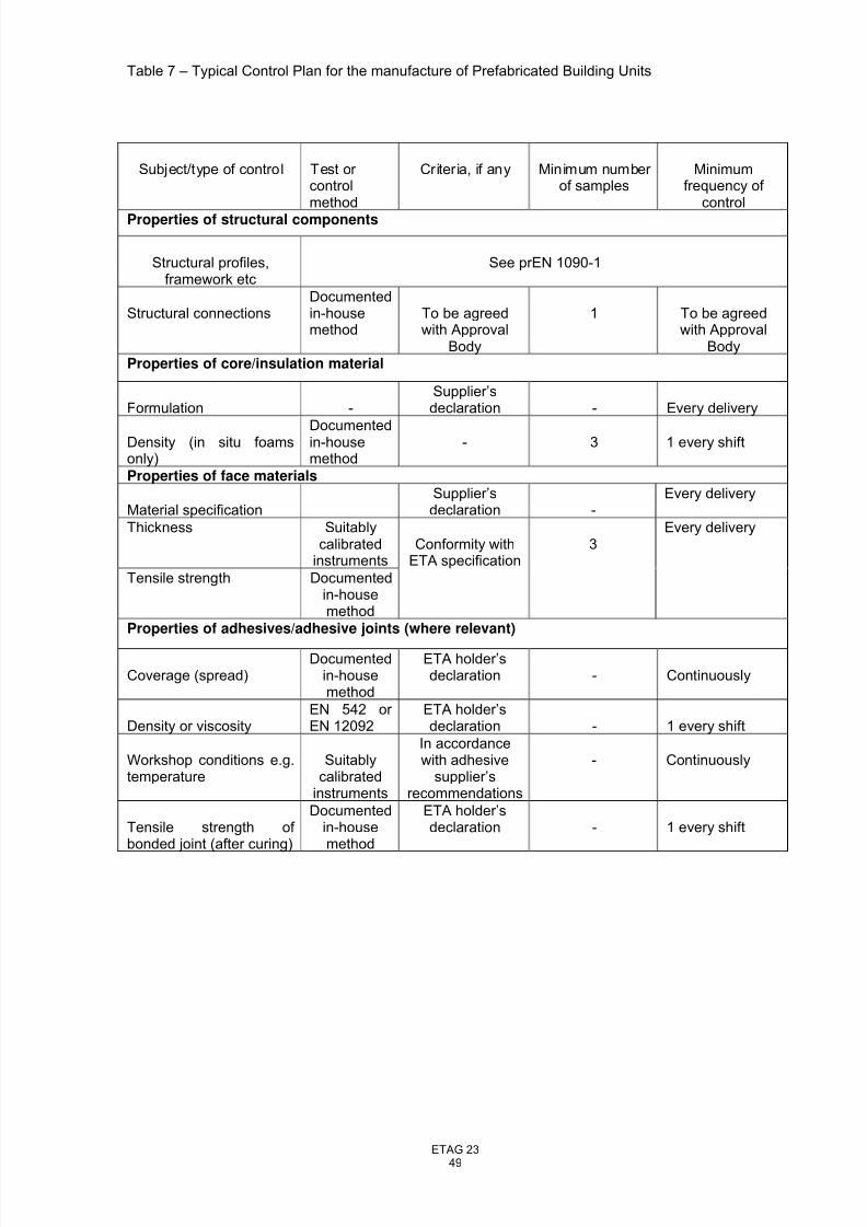
8/14/2019 ETAG023-Draft etag-06.11.23
http://slidepdf.com/reader/full/etag023-draft-etag-061123 49/73
ETAG 2349
Table 7 – Typical Control Plan for the manufacture of Prefabricated Building Units
Subject/type of control Test or controlmethod
Criteria, if any Minimum number of samples
Minimumfrequency of
control
Properties of structural components
Structural profiles,framework etc
See prEN 1090-1
Structural connectionsDocumentedin-housemethod
To be agreedwith Approval
Body
1 To be agreedwith Approval
BodyProperties of core/insulation material
Formulation -Supplier’sdeclaration - Every delivery
Density (in situ foamsonly)
Documentedin-housemethod
- 3 1 every shift
Properties of face materials
Material specificationSupplier’sdeclaration -
Every delivery
Thickness Suitablycalibrated
instruments
Tensile strength Documentedin-housemethod
Conformity withETA specification
3Every delivery
Properties of adhesives/adhesive joints (where relevant)
Coverage (spread)Documented
in-housemethod
ETA holder’sdeclaration - Continuously
Density or viscosityEN 542 or EN 12092
ETA holder’sdeclaration - 1 every shift
Workshop conditions e.g.temperature
Suitablycalibrated
instruments
In accordancewith adhesive
supplier’srecommendations
- Continuously
Tensile strength of bonded joint (after curing)
Documentedin-housemethod
ETA holder’sdeclaration - 1 every shift
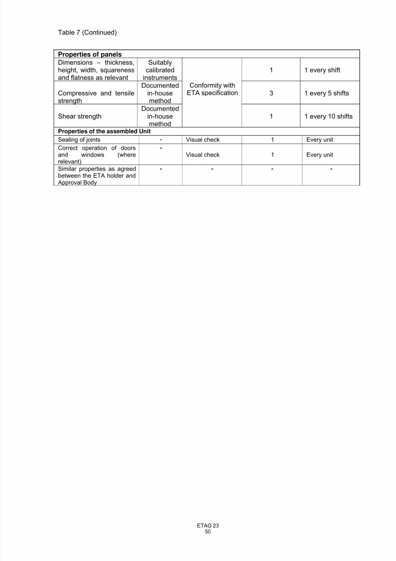
8/14/2019 ETAG023-Draft etag-06.11.23
http://slidepdf.com/reader/full/etag023-draft-etag-061123 50/73
ETAG 2350
Table 7 (Continued)
Properties of panels
Dimensions – thickness,height, width, squarenessand flatness as relevant
Suitablycalibrated
instruments1 1 every shift
Compressive and tensilestrength
Documentedin-housemethod
3 1 every 5 shifts
Shear strengthDocumented
in-housemethod
Conformity withETA specification
1 1 every 10 shifts
Properties of the assembled Unit
Sealing of joints - Visual check 1 Every unit
Correct operation of doorsand windows (whererelevant)
-Visual check 1 Every unit
Similar properties as agreedbetween the ETA holder andApproval Body
- - - -
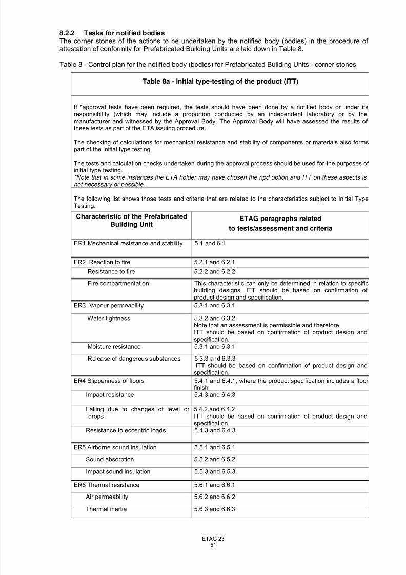
8/14/2019 ETAG023-Draft etag-06.11.23
http://slidepdf.com/reader/full/etag023-draft-etag-061123 51/73
ETAG 2351
8.2.2 Tasks for notified bodiesThe corner stones of the actions to be undertaken by the notified body (bodies) in the procedure of attestation of conformity for Prefabricated Building Units are laid down in Table 8.
Table 8 - Control plan for the notified body (bodies) for Prefabricated Building Units - corner stones
Table 8a - Initial type-testing of the product (ITT)
If *approval tests have been required, the tests should have been done by a notified body or under itsresponsibility (which may include a proportion conducted by an independent laboratory or by themanufacturer and witnessed by the Approval Body. The Approval Body will have assessed the results of these tests as part of the ETA issuing procedure.
The checking of calculations for mechanical resistance and stability of components or materials also formspart of the initial type testing.
The tests and calculation checks undertaken during the approval process should be used for the purposes of initial type testing.*Note that in some instances the ETA holder may have chosen the npd option and ITT on these aspects is not necessary or possible.
The following list shows those tests and criteria that are related to the characteristics subject to Initial TypeTesting.
Characteristic of the PrefabricatedBuilding Unit
ETAG paragraphs related
to tests/assessment and criteria
ER1 Mechanical resistance and stability 5.1 and 6.1
ER2 Reaction to fire 5.2.1 and 6.2.1
Resistance to fire 5.2.2 and 6.2.2
Fire compartmentation This characteristic can only be determined in relation to specificbuilding designs. ITT should be based on confirmation of product design and specification.
ER3 Vapour permeability 5.3.1 and 6.3.1
Water tightness 5.3.2 and 6.3.2Note that an assessment is permissible and thereforeITT should be based on confirmation of product design andspecification.
Moisture resistance 5.3.1 and 6.3.1
Release of dangerous substances 5.3.3 and 6.3.3ITT should be based on confirmation of product design andspecification.
ER4 Slipperiness of floors 5.4.1 and 6.4.1, where the product specification includes a floor finish
Impact resistance 5.4.3 and 6.4.3
Falling due to changes of level or drops
5.4.2.and 6.4.2ITT should be based on confirmation of product design andspecification.
Resistance to eccentric loads 5.4.3 and 6.4.3
ER5 Airborne sound insulation 5.5.1 and 6.5.1
Sound absorption 5.5.2 and 6.5.2
Impact sound insulation 5.5.3 and 6.5.3
ER6 Thermal resistance 5.6.1 and 6.6.1
Air permeability 5.6.2 and 6.6.2
Thermal inertia 5.6.3 and 6.6.3
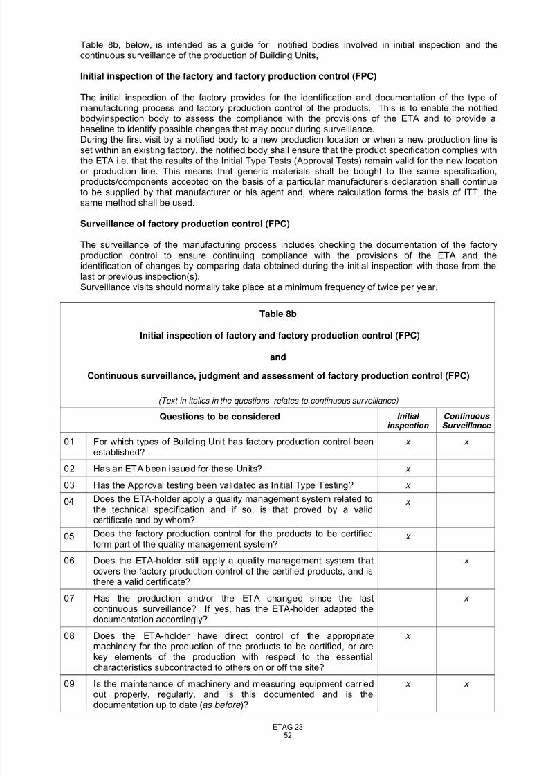
8/14/2019 ETAG023-Draft etag-06.11.23
http://slidepdf.com/reader/full/etag023-draft-etag-061123 52/73
ETAG 2352
Table 8b, below, is intended as a guide for notified bodies involved in initial inspection and thecontinuous surveillance of the production of Building Units,
Initial inspection of the factory and factory production control (FPC)
The initial inspection of the factory provides for the identification and documentation of the type of manufacturing process and factory production control of the products. This is to enable the notifiedbody/inspection body to assess the compliance with the provisions of the ETA and to provide abaseline to identify possible changes that may occur during surveillance.During the first visit by a notified body to a new production location or when a new production line isset within an existing factory, the notified body shall ensure that the product specification complies withthe ETA i.e. that the results of the Initial Type Tests (Approval Tests) remain valid for the new locationor production line. This means that generic materials shall be bought to the same specification,products/components accepted on the basis of a particular manufacturer’s declaration shall continueto be supplied by that manufacturer or his agent and, where calculation forms the basis of ITT, thesame method shall be used.
Surveillance of factory production control (FPC)
The surveillance of the manufacturing process includes checking the documentation of the factoryproduction control to ensure continuing compliance with the provisions of the ETA and theidentification of changes by comparing data obtained during the initial inspection with those from thelast or previous inspection(s).Surveillance visits should normally take place at a minimum frequency of twice per year.
Table 8b
Initial inspection of factory and factory production control (FPC)
and
Continuous surveillance, judgment and assessment of factory production control (FPC)
(Text in italics in the questions relates to continuous surveillance)
Questions to be considered Initial inspection
Continuous Surveillance
01 For which types of Building Unit has factory production control beenestablished?
x x
02 Has an ETA been issued for these Units? x
03 Has the Approval testing been validated as Initial Type Testing? x
04 Does the ETA-holder apply a quality management system related tothe technical specification and if so, is that proved by a validcertificate and by whom?
x
05 Does the factory production control for the products to be certified
form part of the quality management system?
x
06 Does the ETA-holder still apply a quality management system thatcovers the factory production control of the certified products, and isthere a valid certificate?
x
07 Has the production and/or the ETA changed since the lastcontinuous surveillance? If yes, has the ETA-holder adapted thedocumentation accordingly?
x
08 Does the ETA-holder have direct control of the appropriatemachinery for the production of the products to be certified, or arekey elements of the production with respect to the essentialcharacteristics subcontracted to others on or off the site?
x
09 Is the maintenance of machinery and measuring equipment carriedout properly, regularly, and is this documented and is thedocumentation up to date (as before )?
x x
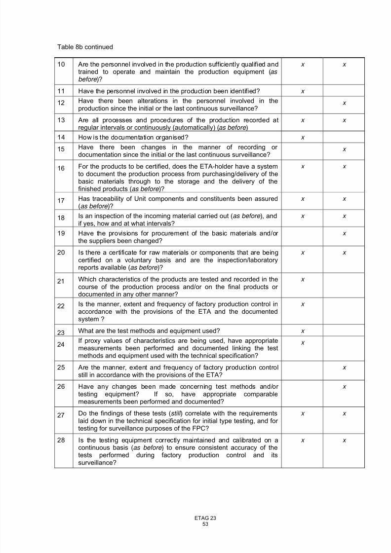
8/14/2019 ETAG023-Draft etag-06.11.23
http://slidepdf.com/reader/full/etag023-draft-etag-061123 53/73
ETAG 2353
Table 8b continued
10 Are the personnel involved in the production sufficiently qualified andtrained to operate and maintain the production equipment (as before )?
x x
11 Have the personnel involved in the production been identified? x
12 Have there been alterations in the personnel involved in theproduction since the initial or the last continuous surveillance?
x
13 Are all processes and procedures of the production recorded atregular intervals or continuously (automatically) (as before )
x x
14 How is the documentation organised? x
15 Have there been changes in the manner of recording or documentation since the initial or the last continuous surveillance?
x
16 For the products to be certified, does the ETA-holder have a systemto document the production process from purchasing/delivery of thebasic materials through to the storage and the delivery of thefinished products (as before )?
x x
17 Has traceability of Unit components and constituents been assured(as before )?
x x
18 Is an inspection of the incoming material carried out (as before ), andif yes, how and at what intervals?
x x
19 Have the provisions for procurement of the basic materials and/or the suppliers been changed?
x
20 Is there a certificate for raw materials or components that are beingcertified on a voluntary basis and are the inspection/laboratoryreports available (as before )?
x x
21 Which characteristics of the products are tested and recorded in thecourse of the production process and/or on the final products or documented in any other manner?
x
22 Is the manner, extent and frequency of factory production control inaccordance with the provisions of the ETA and the documentedsystem ?
x
23 What are the test methods and equipment used? x
24If proxy values of characteristics are being used, have appropriatemeasurements been performed and documented linking the testmethods and equipment used with the technical specification?
x
25 Are the manner, extent and frequency of factory production controlstill in accordance with the provisions of the ETA?
x
26 Have any changes been made concerning test methods and/or testing equipment? If so, have appropriate comparablemeasurements been performed and documented?
x
27 Do the findings of these tests (still ) correlate with the requirementslaid down in the technical specification for initial type testing, and for testing for surveillance purposes of the FPC?
x x
28 Is the testing equipment correctly maintained and calibrated on acontinuous basis (as before ) to ensure consistent accuracy of thetests performed during factory production control and itssurveillance?
x x
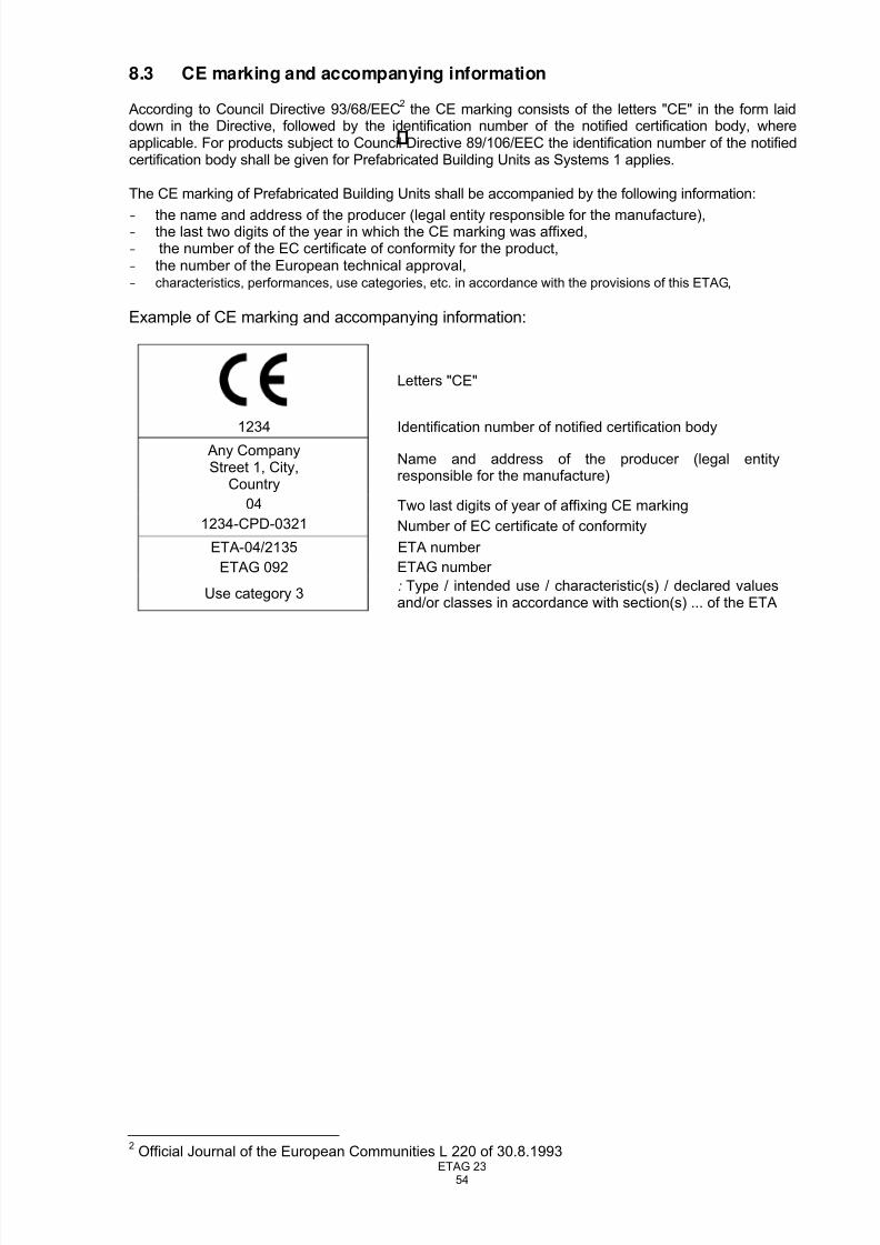
8/14/2019 ETAG023-Draft etag-06.11.23
http://slidepdf.com/reader/full/etag023-draft-etag-061123 54/73
ETAG 2354
8.3 CE marking and accompanying information
According to Council Directive 93/68/EEC2
the CE marking consists of the letters "CE" in the form laiddown in the Directive, followed by the identification number of the notified certification body, whereapplicable. For products subject to Council Directive 89/106/EEC the identification number of the notifiedcertification body shall be given for Prefabricated Building Units as Systems 1 applies.
The CE marking of Prefabricated Building Units shall be accompanied by the following information:
- the name and address of the producer (legal entity responsible for the manufacture),- the last two digits of the year in which the CE marking was affixed,- the number of the EC certificate of conformity for the product,- the number of the European technical approval,- characteristics, performances, use categories, etc. in accordance with the provisions of this ETAG ,
Example of CE marking and accompanying information:
Letters "CE"
1234 Identification number of notified certification body
Any CompanyStreet 1, City,
Country
Name and address of the producer (legal entityresponsible for the manufacture)
04 Two last digits of year of affixing CE marking
1234-CPD-0321 Number of EC certificate of conformity
ETA-04/2135 ETA number
ETAG 092 ETAG number
Use category 3: Type / intended use / characteristic(s) / declared valuesand/or classes in accordance with section(s) ... of the ETA
2
Official Journal of the European Communities L 220 of 30.8.1993
8/14/2019 ETAG023-Draft etag-06.11.23
http://slidepdf.com/reader/full/etag023-draft-etag-061123 55/73
ETAG 2355
SECTION FOUR: ETA CONTENT
9 THE ETA CONTENT
9.1 The ETA
9.1.1 Format
The ETA Format (EC Official Journal L.236 of 27.08.1997) states the content in general.
In section II.2 “characteristics of products and methods of verification“, the ETA shall include thefollowing note:
“In addition to the specific clauses relating to dangerous substances contained in this European Technical Approval, there may be other requirements applicable to the products falling within its scope (e.g. transposed European legislation and national laws, regulations and administrative provisions). In
order to meet the provisions of the EU Construction Products Directive, these requirements need also to be complied with, when and where they apply.”
"The ETA is issued for the product/kit on the basis of agreed data/information, deposited with the Approval Body name}, which identifies the product/kit that has been assessed and judged.Changes to the product/production process/kit, which could result in this deposited data/information being incorrect, should be notified to the {the Approval Body name} before the changes are introduced. The {Approval body name} will decide whether or not such changes affect the ETA and if so whether further assessment/alterations to the ETA, shall be necessary."
9.1.2 Scope
The section entitled Scope of the ETA shall clearly describe the Units, detailing the intended use, the
design system (See Figures 1, 2 and 3) and the rules for and limitations on the assembly of Units intoa finished building – e.g. maximum number of storeys, maximum and minimum number side by side,allowable overhang of upper storeys etc, related to the Units in question. Details shall be given of therules for connections between Units that have been assessed in relation to the ability of finishedbuildings, constructed from the Units, to meet all relevant regulated requirements.
The Scope shall also make clear whether components such as claddings, stairs, roofs (See 2.1 for more details) form part of the Units to be included in the ETA.
Construction products that may be delivered together with the Building Units, but which have not beenassessed by the approval body (ancillary components), shall be clearly separatedfrom those covered by the ETA.
9.1.3 Identification of components
The ETA shall contain information and/or references relating to components and materials used in theconstruction of the Units enabling determination whether the products on the market, or intended to beput on the market, are the approved product as described in the ETA (e.g. for attestation of conformity[see Chapter 8], market surveillance or investigation of complaints or accidents).
When such information/references is/are of a confidential nature it/they shall exist on the ETA filemanaged by the Approval body and as necessary on the relevant file of any Notified body involved.This/these information/references may also be of assistance in any renewal of the ETA. The type,scale, range of information shall be based on the identification paragraphs in Chapter 5 of this ETA-
Guideline.
9.1.4 Product characteristics
The performance characteristics of the Building Units related to the requirements and methods of verification and assessment mentioned in chapters 4, 5 and 6 shall be clearly stated. When a product
8/14/2019 ETAG023-Draft etag-06.11.23
http://slidepdf.com/reader/full/etag023-draft-etag-061123 56/73
ETAG 2356
includes optional designs, such as a set of standard dimensions (thermal insulation thicknesses,loadbearing members etc.), it may be convenient to express these characteristics in table form. Thelatter approach will facilitate the identification, on site, of Units claimed to be the subject of an ETA andbearing CE marking.
9.1.5 Drawings
The ETA document shall include section drawings of the Building Unit(s). The purpose of the drawingsis to illustrate the general build-up of the Unit, ie structural system and loadbearing components,
insulation layers, claddings etc. Material specifications may also be shown directly in these drawingsof the Unit.
If required by the ETA holder, it is permissible to keep some design details confidential, by usingneutral parts in the drawings contained in the ETA, provided the Approval body does not find this inconflict with the need to supply sufficient information to ensure correct application of the product andevaluation of conformity by the Approved body.
In addition, the Unit shall be described by a set of construction details as specified in 9.2. Thesedrawings shall be a formal part of the approval, but are presented as supporting documents and not inthe ETA itself.
9.1.6 Erection details
The ETA shall include particular preconditions linked to the erection details of the building, which theapproval body finds to be of special importance. This may include requirements related to thesubstructure (levels, tolerances etc), completion of joints on site, wind load anchors, roof bracing etc(see also 7.3).Reference shall be made to the ETA holder’s erection instructions.
9.1.7 Estimated working life
The minimum estimated working life of the Units shall be stated and attention drawn to the use of anyshorter life components.
9.1.8 Maintenance
The ETA shall describe basic maintenance, necessary to obtain the minimum estimated working life of the units and the assembled building. (see also 7.4).
9.2 Supporting documents
A set of drawings showing the essential construction details of the Units shall form a supportingdocument as a formal part of the ETA. The purpose of this document is to provide the necessarydetailed description of the Units, including the assembly details on site and the conditions for theinstallation of the Units in the works.
The set of construction details shall describe the general design of the Building Units, including jointswithin the Units i.e. between panels, and joints between the Units when they are assembled in abuilding. The detail drawings shall form the necessary documentation for assessing all the
performance requirements specified in chapter 4, including weather resistance and air permeability.
Only the most essential construction details, which are directly related to the main building parts, andwhich are the pre-designed standard details for the Unit, shall be included.
9.3 Additional information
It shall be stated in the ETA whether or not any additional (possibly confidential) information shall besupplied to the approved body for the attestation of conformity.
8/14/2019 ETAG023-Draft etag-06.11.23
http://slidepdf.com/reader/full/etag023-draft-etag-061123 57/73
ETAG 2357
ANNEX A
COMMON TERMINOLOGY AND ABBREVIATIONS
1. Works and products
1.1 Construction works (and parts of works ) (often simply referred to as “works”)(ID1.3.1)Everything that is constructed or results from construction operations and is fixed to the ground. (This
covers both building and civil engineering works, and both structural and non-structural elements).
1.2 Construction products (often simply referred to as “products”) (ID 1.3.2)Products which are produced for incorporation in a permanent manner in the works and placed assuch on the market.(The term includes materials, elements, components and prefabricated systems or installations.)
1.3 Incorporation (of products in works) (ID 1.3.1)Incorporation of a product in a permanent manner in the works means that:
- its removal reduces the performance capabilities of the works, and
- that the dismantling or the replacement of the product are operations which involve construction
activities.
1.4 Intended use (ID 1.3.4)Role(s) that the product is intended to play in the fulfilment of the essential requirements.
(N.B. This definition covers only the intended use as far as relevant for the CPD)
1.5 Execution (ETAG-format)Used in this document to cover all types of incorporation techniques, such as installation, assembling,
incorporation, etc.
1.6 Kit (EC Guidance Paper C)Construction product consisting of at least two separate components that need to be put together to
be installed permanently in the works (Further clarified for the purpose of this ETAG in the Scope,chap. 2, and in the boxed wording from the Mandate reproduced in the Foreword).
2. Performance
2.1 Fitness for intended use (of products) (CPD 2.1)Means that the products have such characteristics that the works in which they are intended to be
incorporated, assembled, applied or installed, can, if properly designed and built, satisfy the essentialrequirements.(N.B. This definition covers only the intended fitness for intended use as far as relevant for the CPD)
2.2 Serviceability (of works)Ability of the works to fulfil their intended use and in particular the essential requirements relevant for
this use.
The products must be suitable for construction works which (as a whole and in their separate parts)
are fit for their intended use, subject to normal maintenance, be satisfied for an economicallyreasonable working life. The requirements generally concern actions which are foreseeable (CPDAnnex I, Preamble).
2.3 Essential requirements (for works)Requirements applicable to works, which may influence the technical characteristics of a product, and
are set out in objectives in the CPD, Annex I (CPD, art. 3.1).
2.4 Performance (of works, parts of works or products) (ID 1.3.7)
8/14/2019 ETAG023-Draft etag-06.11.23
http://slidepdf.com/reader/full/etag023-draft-etag-061123 58/73
ETAG 2358
The quantitative expression (value, grade, class or level) of the behaviour of the works, parts of works
or of the products, for an action to which it is subject or which it generates under the intended serviceconditions (works or parts of works) or intended use conditions (products).
As far as practicable the characteristics of products, or groups of products, should be described inmeasurable performance terms in the technical specifications and guidelines for ETA. Methods of calculation, measurement, testing (where possible), evaluation of site experience and verification,together with compliance criteria shall be given either in the relevant technical specifications or in
references called up in such specifications.
2.5 Actions (on works or parts of the works) (ID 1.3.6)Service conditions of the works which may affect the compliance of the works with the essential
requirements of the Directive and which are brought about by agents (mechanical, chemical,biological, thermal or electro-mechanical) acting on the works or parts of the works.Interactions between various products within a work are considered as "actions".
2.6 Classes or levels (for essential requirements and for related product performances) (ID 1.2.1)A classification of product performance(s) expressed as a range of requirement levels of the works,
determined in the ID's or according to the procedure provided for in art. 20.2a of the CPD.
3. ETAG-Format
3.1 Requirements (for works) (ETAG-format 4)Expression and application, in more detail and in terms applicable to the scope of the guideline, of the
relevant requirements of the CPD (given concrete form in the ID's and further specified in themandate, for works or parts of the works, taking into account the durability and serviceability of theworks.
3.2 Methods of verification (for products) (ETAG-format 5)Verification methods used to determine the performance of the products in relation to the requirements
for the works (calculations, tests, engineering knowledge, evaluation of site experience, etc.)
These verification methods are related only to the assessment of, and for judging the fitness for use.Verification methods for particular designs of works are called here "project testing", for identification of products are called "identification testing", for surveillance of execution or executed works are called "surveillance testing", and for attestation of conformity are called "AC-testing".
3.3 Specifications (for products) (ETAG-format 6)Transposition of the requirements into precise and measurable (as far as possible and proportional to the
importance of the risk) or qualitative terms, related to the products and their intended use. The satisfaction of the specifications is deemed to satisfy the fitness for use of the products concerned.
Specifications may also be formulated with regard to the verification of particular designs, for identification of products, for surveillance of execution or executed works and for attestation of conformity, when relevant.
4. Working life 4.1 Working life (of works or parts of the works) (ID 1.3.5(1))The period of time during which the performance will be maintained at a level compatible with the
fulfilment of the essential requirements.
4.2 Working life (of products)Period of time during which the performance of the product is maintained - under the corresponding
service conditions - at a level compatible with the intended use conditions.
4.3 Economically reasonable working life (ID 1.3.5(2))Working life which takes into account all relevant aspects, such as costs of design, construction and
use, costs arising from hindrance of use, risks and consequences of failure of the works during its
working life and cost of insurance covering these risks, planned partial renewal, costs of inspections,maintenance, care and repair, costs of operation and administration, of disposal and environmentalaspects.
8/14/2019 ETAG023-Draft etag-06.11.23
http://slidepdf.com/reader/full/etag023-draft-etag-061123 59/73
ETAG 2359
4.4 Maintenance (of works) (ID 1.3.3(1))A set of preventative and other measures, which are applied to the works in order to enable the works
to fulfil all its functions during its working life. These measures include cleaning, servicing, repainting,repairing, replacing parts of the works where needed, etc.
4.5 Normal maintenance (of works) (ID 1.3.3(2))Maintenance, normally including inspections, which occurs at a time when the cost of the intervention
which has to be made is not disproportionate to the value of the part of the work concerned,
consequential costs (e.g. exploitation) being taken into account.
4.6 Durability (of products)Ability of the product to contribute to the working life of the work by maintaining its performances,
under the corresponding service conditions, at a level compatible with the fulfilment of the essentialrequirements by the works.
5. Conformity
5.1 Attestation of conformity (of products)Provisions and procedures as laid down in the CPD and fixed according to the directive, aiming to
ensure that, with acceptable probability, the specified performance of the product is achieved by theongoing production.
5.2 Identification (of a product)Product characteristics and methods for their verification, allowing comparison of a given product with
that described in the technical specification.
6. Approval and approved bodies
6.1. Approval Body Body notified in accordance with Article 10 of the CPD, by an EU Member State or by an EFTA State(contracting party to the EEA Agreement), to issue European Technical Approvals in (a) specificconstruction product area(s). All such bodies are required to be members of the EuropeanOrganisation for Technical Approvals (EOTA), set up in accordance with Annex II.2 of the CPD.
6.2. Approved Body(*) Body nominated in accordance with Article 18 of the CPD, by an EU Member State or by an EFTAState (contracting party to the EEA Agreement), to perform specific tasks in the framework of theAttestation of Conformity decision for specific construction products (certification, inspection or testing). All such bodies are automatically members of the Group of Notified Bodies.
(*) Also known as Notified Body
8/14/2019 ETAG023-Draft etag-06.11.23
http://slidepdf.com/reader/full/etag023-draft-etag-061123 60/73
ETAG 2360
Abbreviations
Concerning the Construction products directive:
AC: Attestation of conformity
CEC: Commission of the European CommunitiesCEN: Comité Européen de Normalisation ((European Committee for Standardization)
CPD: Construction Products DirectiveEC: European CommunitiesEFTA: European Free Trade AssociationEN: European StandardFPC: Factory production controlID: Interpretative Documents of the CPDISO: International Standardisation OrganisationSCC: Standing Committee for Construction of the EC.
Concerning approval:
EOTA: European Organisation for Technical Approvals
ETA: European Technical ApprovalETAG: European Technical Approval GuidelineTB: EOTA - Technical BoardUEAtc: Union Européenne pour l’Agrément Technique dans la Construction (European Union of
Agrément).
General:
TC: Technical committeeWG: Working group.
8/14/2019 ETAG023-Draft etag-06.11.23
http://slidepdf.com/reader/full/etag023-draft-etag-061123 61/73
ETAG 2361
ANNEX B
LIST OF REFERENCE STANDARDS
Verification of loadbearing capacity
EN 1990 Eurocode: Basis of Structural Design EN 1991 Eurocode 1: Actions on Structures The relevant material-specific Eurocodes are:
- EN 1992 Eurocode 2: Design of Concrete Structures - EN 1993 Eurocode 3: Design of Steel Structures - EN 1994 Eurocode 4: Design of Composite Steel and Concrete Structures - EN 1995 Eurocode 5: Design of Timber Structures - EN 1999 Eurocode 9: Design of Aluminium Structures
EN 1998: Eurocode 8: Design of structures for earthquake resistance EN 380:1993 Timber structures - Test methods - General principles for static load testing EN 594:1995 Timber structures - Test methods - Racking strength and stiffness of timber frame wall
panels EN 595:1995 Timber structures - Test methods - Test of trusses for the determination of strength and deformation behaviour EN 596:1995 Timber structures - Test methods - Soft body impact test of timber framed walls EN 789:1996 Timber structures - Test methods – Mechanical properties of wood based panels EN 1095:1997 Timber structures - Product requirements for prefabricated trusses using punched metal plate fasteners EN 1195:1997 Timber structures - Test methods - Performance of structural floor decking PrEN 12871:Wood-based panels. Structural roof decking on joists.
EOTA Technical Report XXX – Interpretation of results of structural tests (Under preparation with CEN TC 250)
Verification of fire resistance and reaction to fire Eurocode 1: Basis for design and actions on structures - Part 2-2: Actions on structures - Actions on structures exposed to fire Eurocode 5: Design of timber structures - Part 1-2: General rules - Structural fire design EN 1363-1:1999 Fire resistance tests – Part 1: General requirements EN ISO 9239-1 Reaction to fire tests for floorings – Part 1: Determination of the burning behaviour using a radiant heat source.EN 13501 Fire classification of construction products and building elements Part 1 Classification using data from reaction to fire tests Part 2 Classification using data from fire resistance tests, excluding ventilation services (prEN)Part 5 Classification using data from external fire exposure tests on roofs
Verification of resistance against weather effects
EN 1027 Windows and doors - Water tightness - Test method prEN 12155 Curtain walling - Water tightness - Laboratory test under static pressure prEN 12865-1 Hygrothermal performance of buildings – Determination of resistance to driving rain under pulsating air pressure – Part 1: External wall systems
Verification of water vapour resistance
EN 12524 : 2000 Building materials and products. Hygrothermal properties. Tabulated design values EN ISO 12572 :1997 Determination of Water Vapour Transmission Properties EN ISO 13788 Hygrothermal performance of building components and building elements - Internal
surface temperature to avoid critical surface humidity and interstitial condensation - Calculation methods
8/14/2019 ETAG023-Draft etag-06.11.23
http://slidepdf.com/reader/full/etag023-draft-etag-061123 62/73
ETAG 2362
Verification of safety in use
EOTA Technical Report TR001 Feb 2003 Determination of impact resistance of panels and panel assemblies EN 1195 Timber structures - Test methods - performance of structural floor decking
Verification of sound insulation performance
EN ISO 140 Acoustics - Measurement of sound insulation in buildings and of building elements EN ISO 354 Acoustics - Measurement of sound absorption in a reverberation room EN ISO 717 / EN 20717 Part 1 and 2 Acoustics - Rating of sound insulation in buildings and of building elements.EN 12354-1 Building acoustics - Estimation of acoustic performance of buildings from the performance of elements -1 Part 1: Airborne sound insulation between rooms -2 Part 2: Impact sound insulation between rooms -3 Part 3: Airborne sound insulation against outdoor sound -4 Part 4: Transmission of indoor sound to the outside -6 Part 6: Sound absorption in enclosed spaces
Verification of thermal insulation
EN 832 Thermal performance of buildings - Calculation of energy use for heating - Residential buildings EN ISO 6946:1996 Building components and building elements - Thermal resistance and thermal transmittance- Calculation method EN ISO 8990:1996 Thermal insulation - Determination of steady-state thermal transmission properties - Calibrated and guarded hot box.EN 10077-1 Thermal performance of windows, doors and shutters – Calculation of thermal transmittance – Part 1: Simplified method PrEN 10077 2 EN ISO 10211-1:1995 Thermal bridges in building construction - Heat flows and surface temperatures
–Part 1: General calculation methods prEN ISO 10211-2 Thermal bridges in building construction - Heat flows and surface temperatures – Part 2: Linear thermal bridges EN 10456 :1999 Thermal insulation - Building materials and components - Determination of declared values and design thermal values EN 12524 Building materials and products - Hygrothermal properties - Tabulated design values EN ISO 13788 Hygrothermal performance of building components and building elements - Internal surface temperature to avoid critical surface humidity and interstitial condensation - Calculation methods
Verification of airtightness
EN 1026:2000 Windows and doors - Air permeability - Test method
EN 12114:2000 Thermal performance of buildings. Air permeability of building components andbuilding elements. Laboratory test methods.EN 13829 Thermal insulation - Determination air permeability of buildings – Fan pressurisation method (ISO 9972:1996, modified)
Verification of durability
EN 335 Hazard classes of wood and wood-based products against biological attack:- EN 335 -1:1992 Classification of hazard classes EN 335-2:1992 Guide to the application of hazard classes to solid wood EN 335-3:1995 Application to wood-based panels EN 350-1:1995 Durability of wood and wood based products - Preservative-treated solid wood - Part 1: Classification of preservative penetration and retention EN 350-2:1994 Durability of wood and wood based products - Natural durability of solid wood - Part 2: Guide to natural durability and treatability of selected wood species of importance in Europe EN 594:1995 Timber structures. Test methods. Racking strength and stiffness of timber-framed wall panels.EN 607 Eaves gutters and fittings made of PVC-U - Definitions, requirements and testing
8/14/2019 ETAG023-Draft etag-06.11.23
http://slidepdf.com/reader/full/etag023-draft-etag-061123 63/73
ETAG 2363
EN 1462 Brackets for eaves gutters - requirements and testing EN 612 Eaves gutters with bead stiffened fronts and rainwater pipes with seamed joints made of metal sheet EN 743:1994 Plastics piping and ducting systems. Thermoplastic pipes. Determination of longitudinal reversion.EN 1396 Aluminium and aluminium alloys - Coil coated sheet and strip for general applications – Specifications EN 1607:1997 Thermal insulating products for building applications - Determination of tensile strength perpendicular to faces EN 10088-1:1995 List of stainless steels EN 10169:1996 Continuously organically coated (Coil coated) steel flat products. – General information (Definitions, materials, tolerances, test methods)EN ISO 10590:1997 Building construction. Sealants. Determination of adhesion/cohesion properties at maintained extension after immersion in water.ISO 11431:1993 Building construction. Determination of adhesion/cohesion after exposure to artificial light through glass.ISO 11600 : 1993 Building construction. Sealants. Classification and requirements.EN ISO 12944 Paints and varnishes. Corrosion protection of steel structures by protective paint systems.EN 12365-1 Building hardware – Gaskets and weatherstripping for doors, windows, shutters and
curtain walling – Part 1; Performance requirements and classification.EN 13245-1Plastics-Unplasticised poly(vinyl) chloride( (PVC-U) profiles for building applications – Part
1: Designation of light coloured profiles.2:Profiles for internal and external wall and ceiling finishes 3:Designation of coloured profiles
EN14351 Windows and external pedestrian doors. Product standard.prEN 14509 Metal faced sandwich panels EN ISO 14713:1999 Protection against corrosion of iron and steel in structures. Zinc and aluminium coatings. Guidelines.
Harmonised Standards for Pre-cast Concrete
EN 1168, Pre-cast concrete products – Hollow core slabs
EN 13225, Pre-cast concrete products – Linear structural elements
EN 13693, Pre-cast concrete products – Special roof elements
EN 13747, Pre-cast concrete products – Floor plates for floor systems
EN 13978, Pre-cast concrete products – Pre-cast concrete garages
EN 13224, Pre-cast concrete products – Ribbed floor elements
prEN 14843, Pre-cast concrete products – Stairs
prEN 14992, Pre-cast concrete products - Wall elements : Products properties and performance
prEN 15037-1, Pre-cast concrete products - Beam-and-block floor systems - Part 1: Beams
prEN 15037-2, Pre-cast concrete products - Beam-and-block floor systems - Part 2: Concrete blocks
Miscellaneous
ETAG 003.Internal Partition Kits
ETAG 008 Prefabricated Stair Kits ETAG 016 Composite Lightweight Panels ETAG 017 Vetures ETAG 021 Cold storage Premises Kits – Part 2: Cold Storage Building Envelope and Building Kits ETAG 022 Watertight coverings for bathrooms EOTA Guidance Document 004 The Provisions of Data for Assessments Leading to ETA.
8/14/2019 ETAG023-Draft etag-06.11.23
http://slidepdf.com/reader/full/etag023-draft-etag-061123 64/73
8/14/2019 ETAG023-Draft etag-06.11.23
http://slidepdf.com/reader/full/etag023-draft-etag-061123 65/73
ETAG 2365
the roof, with up-stand perimeter walls, to enable the required depth of water to be applied above theroof.
h. Dial gauges or transducers to an accuracy of 0.1 mm shall be positioned at the locations where themaximum deflection is expected and cover both vertical deflection and horizontal movement.
i. Load shall be applied in four equal increments up to the declared design load. (Serviceability roof load).
j. Record any observations regarding movements, creaking, local damage, etc,
Note: For the following ultimate failure test it is only necessary to test the fully loaded situation .
k. The roof shall then be subjected to gradually increased load until it reaches the maximum test load(see clause 5.1.3.2.2) and any observations or damage should be recorded.
l. Examine the Unit and report any sign of permanent damage.
m. The floor shall then be subjected to gradually increased load until it reaches the maximum test load(see clause 5.1.3.2.2) and any observations or damage should be recorded.
n. Examine the Unit and report any sign of permanent damage.
o. The test may be extended to cover the ability of the Unit to withstand loading from Units above. Insuch cases, the load shall be applied to the Unit at the location appropriate to the design approachand the values calculated in accordance with the principles outlined for floors and roofs.
C.5 Supplementary tests
It is necessary to establish that the factor of safety for joints between components is no worse than thevalue used if joints are designed by calculation to an appropriate Eurocode.If calculations cannot be provided to verify compliance with the appropriate Eurocode then testsshould be carried to determine its ultimate resistance to the anticipated mode of failure when installedin the Unit. Such tests shall verify that the joints have an equivalent factor of safety to calculated
values.For example, the maximum design load for a connection between two steel members utilisingstandard bolts and normal hole sizes can be evaluated by using the Eurocode. However, if theconnection is between two thin members and a pressed indentation increases the shear capacity thentests would be necessary.Such tests should be set-up and carried out in accordance with the principles of EN 1990.A minimum of three tests is normally necessary to derive the characteristic values that, when factoredappropriately, should derive adequate ultimate resistance to failure.
8/14/2019 ETAG023-Draft etag-06.11.23
http://slidepdf.com/reader/full/etag023-draft-etag-061123 66/73
ETAG 2366
ANNEX D
TEST SPECIFICATION FOR VERIFICATION OF RACKING RESISTANCE OF ELEMENTS OF BUILDING
UNITS.
D.1 Objective
The objective of these tests is to determine the racking resistance provided by the vertical wallelements of a Building Unit.
D.2 Principle
The test method measures the resistance to racking load of panels or vertical wall elements,which can deform both vertically and horizontally in the plane of the panel.
In this test method, the panel is fastened to the substrate in accordance with manufacturer'sspecifications, ensuring that the test result corresponds with behaviour in normal use.
D.3 References
This test method is derived from the following reference documents:
- ASTM E72-98 Standard test methods of conducting strength tests of panels for building construction
- EN 594:1996 Timber structures - Test methods - Racking strength and stiffness of timber frame wall panels
D.4 Definitions
racking strength:
capacity of a panel to resist a horizontal load in the plane of the panel
racking stiffness:
calculated stiffness of a panel when it is loaded to approximately 40% of its racking strength
D.5 Symbols
F applied racking load, in N;F max maximum racking load, in N;F max,est estimated maximum racking load, in N;F y applied vertical load, in N;R racking stiffness, in N/mm;
ν panel deformation, in mm.
D.6 Test Specimen
The test specimen should have the maximum height and width of the components covered bythe ETA. An example is shown in Figure D.1.
Notes:1) Typical test specimens are 2,4 m x 2,4 m panels or panels the width and height of the building unit.2) Typical panel types for building units that should be tested include:- An external wall end with maximum window opening — the preferred size for this element is the
maximum actual height by the maximum width of the end panel to be covered by the ETA- An external wall with no window opening- An internal non load-bearing wall panel
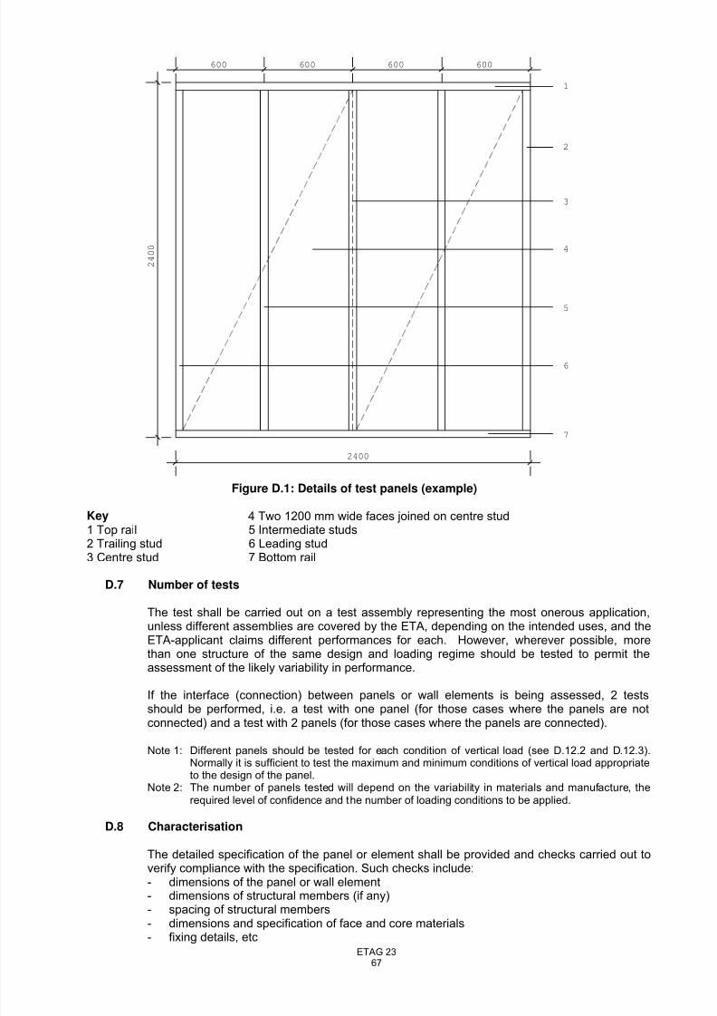
8/14/2019 ETAG023-Draft etag-06.11.23
http://slidepdf.com/reader/full/etag023-draft-etag-061123 67/73
ETAG 2367
600 600 600 600
2400
2 4 0 0
1
2
3
4
5
6
7
Figure D.1: Details of test panels (example)
Key 4 Two 1200 mm wide faces joined on centre stud
1 Top rail 5 Intermediate studs2 Trailing stud 6 Leading stud3 Centre stud 7 Bottom rail
D.7 Number of tests
The test shall be carried out on a test assembly representing the most onerous application,unless different assemblies are covered by the ETA, depending on the intended uses, and theETA-applicant claims different performances for each. However, wherever possible, morethan one structure of the same design and loading regime should be tested to permit theassessment of the likely variability in performance.
If the interface (connection) between panels or wall elements is being assessed, 2 tests
should be performed, i.e. a test with one panel (for those cases where the panels are notconnected) and a test with 2 panels (for those cases where the panels are connected).
Note 1: Different panels should be tested for each condition of vertical load (see D.12.2 and D.12.3).Normally it is sufficient to test the maximum and minimum conditions of vertical load appropriateto the design of the panel.
Note 2: The number of panels tested will depend on the variability in materials and manufacture, therequired level of confidence and the number of loading conditions to be applied.
D.8 Characterisation
The detailed specification of the panel or element shall be provided and checks carried out toverify compliance with the specification. Such checks include:- dimensions of the panel or wall element- dimensions of structural members (if any)- spacing of structural members- dimensions and specification of face and core materials- fixing details, etc
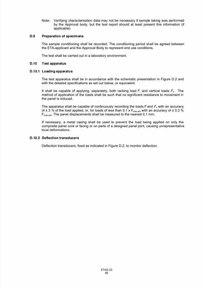
8/14/2019 ETAG023-Draft etag-06.11.23
http://slidepdf.com/reader/full/etag023-draft-etag-061123 68/73
ETAG 2368
Note: Verifying characterisation data may not be necessary if sample taking was performedby the Approval body, but the test report should at least present this information (if applicable).
D.9 Preparation of specimens
The sample conditioning shall be recorded. The conditioning period shall be agreed betweenthe ETA-applicant and the Approval Body to represent end use conditions.
The test shall be carried out in a laboratory environment.
D.10 Test apparatus
D.10.1 Loading apparatus
The test apparatus shall be in accordance with the schematic presentation in Figure D.2 andwith the detailed specifications as set out below, or equivalent.
It shall be capable of applying, separately, both racking load F, and vertical loads F v . Themethod of application of the loads shall be such that no significant resistance to movement inthe panel is induced.
The apparatus shall be capable of continuously recording the loads F and F v with an accuracyof ± 3 % of the load applied, or, for loads of less than 0,1 x Fmax,est with an accuracy of ± 0,3 %Fmax,est. The panel displacements shall be measured to the nearest 0,1 mm.
If necessary, a metal casing shall be used to prevent the load being applied on only thecomposite panel core or facing or on parts of a designed panel joint, causing unrepresentativelocal deformations.
D.10.2 Deflection transducers
Deflection transducers, fixed as indicated in Figure D.2, to monitor deflection.
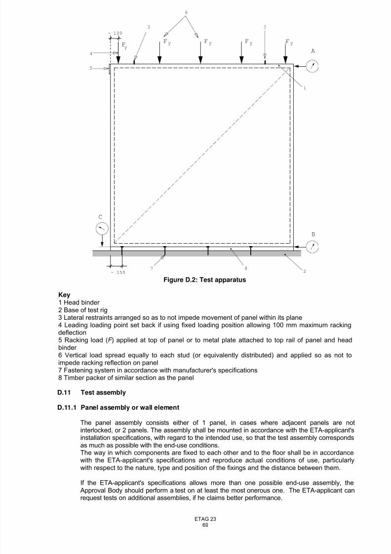
8/14/2019 ETAG023-Draft etag-06.11.23
http://slidepdf.com/reader/full/etag023-draft-etag-061123 69/73
ETAG 2369
D.11 Test assembly
D.11.1 Panel assembly or wall element
The panel assembly consists either of 1 panel, in cases where adjacent panels are notinterlocked, or 2 panels. The assembly shall be mounted in accordance with the ETA-applicant'sinstallation specifications, with regard to the intended use, so that the test assembly correspondsas much as possible with the end-use conditions.The way in which components are fixed to each other and to the floor shall be in accordancewith the ETA-applicant's specifications and reproduce actual conditions of use, particularlywith respect to the nature, type and position of the fixings and the distance between them.
If the ETA-applicant's specifications allows more than one possible end-use assembly, theApproval Body should perform a test on at least the most onerous one. The ETA-applicant canrequest tests on additional assemblies, if he claims better performance.
Fy
Fy Fy Fy Fy
~ 150
A
B
C
~ 100
3 3
6
4
5
1
287
Figure D.2: Test apparatus
Key1 Head binder 2 Base of test rig3 Lateral restraints arranged so as to not impede movement of panel within its plane4 Leading loading point set back if using fixed loading position allowing 100 mm maximum rackingdeflection5 Racking load (F ) applied at top of panel or to metal plate attached to top rail of panel and headbinder 6 Vertical load spread equally to each stud (or equivalently distributed) and applied so as not toimpede racking reflection on panel7 Fastening system in accordance with manufacturer's specifications8 Timber packer of similar section as the panel
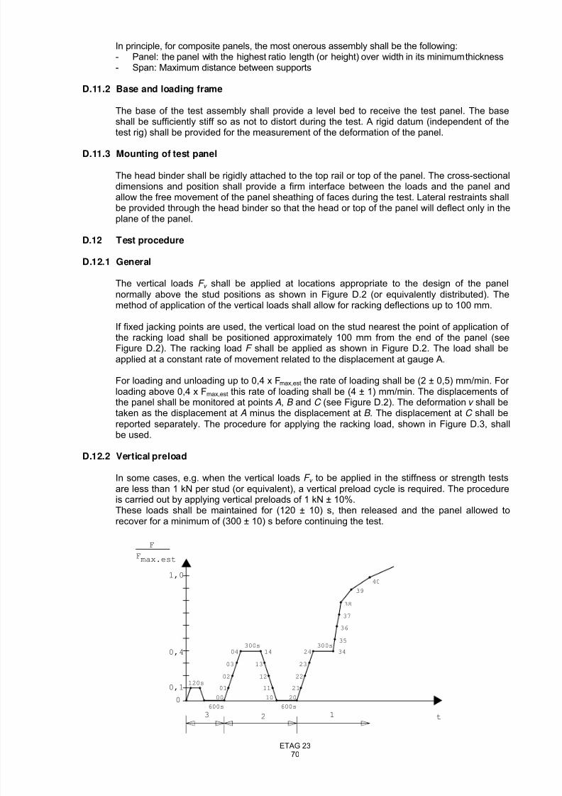
8/14/2019 ETAG023-Draft etag-06.11.23
http://slidepdf.com/reader/full/etag023-draft-etag-061123 70/73
ETAG 2370
In principle, for composite panels, the most onerous assembly shall be the following:- Panel: the panel with the highest ratio length (or height) over width in its minimum thickness- Span: Maximum distance between supports
D.11.2 Base and loading frame
The base of the test assembly shall provide a level bed to receive the test panel. The baseshall be sufficiently stiff so as not to distort during the test. A rigid datum (independent of thetest rig) shall be provided for the measurement of the deformation of the panel.
D.11.3 Mounting of test panel
The head binder shall be rigidly attached to the top rail or top of the panel. The cross-sectionaldimensions and position shall provide a firm interface between the loads and the panel andallow the free movement of the panel sheathing of faces during the test. Lateral restraints shallbe provided through the head binder so that the head or top of the panel will deflect only in theplane of the panel.
D.12 Test procedure
D.12.1 General
The vertical loads F v shall be applied at locations appropriate to the design of the panelnormally above the stud positions as shown in Figure D.2 (or equivalently distributed). Themethod of application of the vertical loads shall allow for racking deflections up to 100 mm.
If fixed jacking points are used, the vertical load on the stud nearest the point of application of the racking load shall be positioned approximately 100 mm from the end of the panel (seeFigure D.2). The racking load F shall be applied as shown in Figure D.2. The load shall beapplied at a constant rate of movement related to the displacement at gauge A.
For loading and unloading up to 0,4 x Fmax,est the rate of loading shall be (2 ± 0,5) mm/min. For loading above 0,4 x Fmax,est this rate of loading shall be (4 ± 1) mm/min. The displacements of the panel shall be monitored at points A, B and C (see Figure D.2). The deformation v shall betaken as the displacement at A minus the displacement at B . The displacement at C shall bereported separately. The procedure for applying the racking load, shown in Figure D.3, shallbe used.
D.12.2 Vertical preload
In some cases, e.g. when the vertical loads F v to be applied in the stiffness or strength testsare less than 1 kN per stud (or equivalent), a vertical preload cycle is required. The procedureis carried out by applying vertical preloads of 1 kN ± 10%.These loads shall be maintained for (120 ± 10) s, then released and the panel allowed torecover for a minimum of (300 ± 10) s before continuing the test.
1,0
0,4
0,1
0
120s
600s 600s
t
F
Fmax.est
300s 300s
00 10 20
01 11 21
02 12 22
03 13 23
04 14 24 34
35
36
37
38
39
40
123
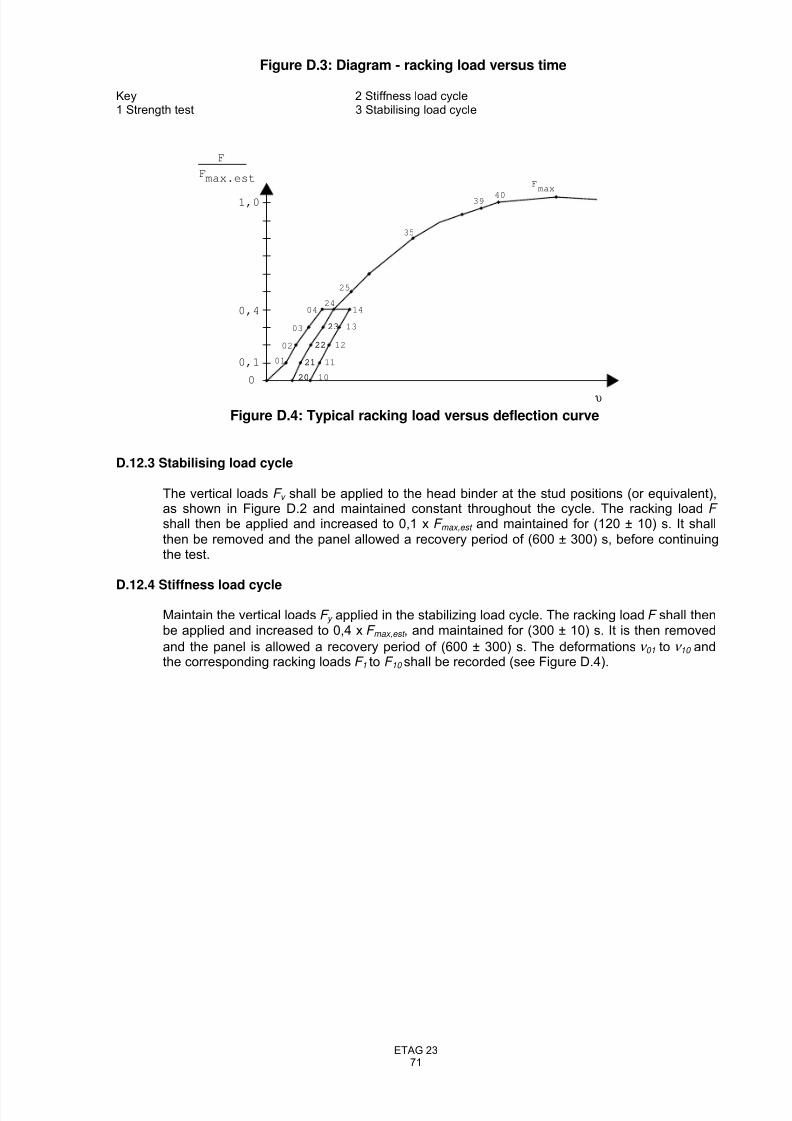
8/14/2019 ETAG023-Draft etag-06.11.23
http://slidepdf.com/reader/full/etag023-draft-etag-061123 71/73
ETAG 2371
Figure D.3: Diagram - racking load versus time
Key 2 Stiffness load cycle1 Strength test 3 Stabilising load cycle
F
Fmax.est
υ
1,0
0,4
0,1
0
Fmax
4039
35
25
24
23
22
21
20
23
22
21
20
14
12
11
10
04
03
02
01
13
Figure D.4: Typical racking load versus deflection curve
D.12.3 Stabilising load cycle
The vertical loads F v shall be applied to the head binder at the stud positions (or equivalent),as shown in Figure D.2 and maintained constant throughout the cycle. The racking load F shall then be applied and increased to 0,1 x F max,est and maintained for (120 ± 10) s. It shallthen be removed and the panel allowed a recovery period of (600 ± 300) s, before continuingthe test.
D.12.4 Stiffness load cycle
Maintain the vertical loads F y applied in the stabilizing load cycle. The racking load F shall thenbe applied and increased to 0,4 x F max,est , and maintained for (300 ± 10) s. It is then removed
and the panel is allowed a recovery period of (600 ± 300) s. The deformations ν 01 to ν 10 andthe corresponding racking loads F 1 to F 10 shall be recorded (see Figure D.4).
8/14/2019 ETAG023-Draft etag-06.11.23
http://slidepdf.com/reader/full/etag023-draft-etag-061123 72/73
ETAG 2372
D.12.5 Strength test
Maintain the vertical loads F v applied in the stabilizing load cycle. The racking load F = 0,4 x F max.,est shall then be applied and this load shall be maintained for (300 ± 10) s. The rackingload F shall then be increased until Fmax is reached. The racking load shall be applied at therate specified above (see D.12.1).
Note 1. The rate of loading should ensure that 90 % of the racking load F max is reached within (300 ±120) s. It is advised that the mean time to this load is about 300 s.
Note 2. See D.12.2 for a description of the relationship between F max,est and F max
F max is reached when either:- the panel collapses, or - the panel attains a deformation v (see D.12.1) of 100 mm, whichever occurs first.
The deformations ν 20 and ν 40 and the corresponding racking loads shall be recorded (see FigureD.4).
Note 3 It is important to ensure that the panel has totally failed when the racking load begins to reduce;it is common for panels to recover the load lost when individual fixings fail by redistributing theload to the remaining fixings.
D.12.6 Expression of results
The test results shall contain:
a) racking stiffness of the panel, calculated from the equation
R = 0,5 x ((F 4 - F 1)/(ν 04 - ν 01)+(F 24 - F 21) / (ν 24 - ν 21))Where:
F1 is the racking load of 0,1 x F max,est, in N, and ν 01 is the deformation, in mm, and
F4 is the racking load of 0,4 x F max,est , in N, and ν 04 is the deformation, in mm asdetermined in the stiffness test;
F2l is the racking load of 0,1 x -F max,est , in N, and ν 21 is the deformation, in mm and
F24 is the racking load of 0,4 X F max,est , in N, and ν 24 is the deformation, in mm,as determined in the strength test;
b) racking strength, expressed as the value of the maximum racking load F max as foundin the strength test;
c) vertical loads F v the total vertical load, and the nominal spacing of the studs (if
relevant);d) a record of the displacement at C (see Figure D.2).
Note: The estimated maximum racking load F max,est shall be determined on the basis of experience,calculation or preliminary tests. If F max,est deviates by more than 20 % from a mean value of F max
obtained for all similar tests, the value of R for that test shall be rejected.
D.13 Test report
The test report shall include at least the following information:
a) reference to this EOTA ETA-Guideline, Annex Db) the name of the testing laboratoryc) the name of the ETA-Applicant (and manufacturer of the product, if different)d) date of the teste) description of the test instrumentsf) identification of the product tested (designation, dimensions and any relevant
identification characteristic, e.g. moisture content of the timber framing and thesheathing material)
g) identification of the sample(-s) tested (dimensions, shape, etc.) and reference to itsmarking (if any)
h) surface structure (e.g. smooth, profiled, structured, …)i) description of conditioning and preparation of the sample (if any) j) the rate of applying the loadk) description of test conditions (temperature and RH)
l) test loads attained during the tests together with the corresponding deformations at allmeasurement positions; the vertical loads Fv applied in the racking stiffness andstrength tests
m) values of R and F max and the circumstances in which -F max occurred;
8/14/2019 ETAG023-Draft etag-06.11.23
http://slidepdf.com/reader/full/etag023-draft-etag-061123 73/73
n) gap between the sheets in the panel (if any);o) direction of greater strength of the sheathing material;p) specification of the mechanical fasteners (including corrosion protection), and their
quantity and positioning;q) any deviation in panel construction from that shown in Figure D.1;r) description of the method of loading the panel and of measuring the panel
deformations;
s) type and position of any failure, including failures that have no relationship with theracking resistance of the panel (e.g. failure of the connection to the substrate);