etag 001 annex b
TRANSCRIPT
ETAG 001 Edition 1997
GUIDELINE FOR EUROPEAN TECHNICAL APPROVAL OF
METAL ANCHORS FOR USE IN CONCRETE
Annex B: TESTS FOR ADMISSIBLE SERVICE CONDITIONS
DETAILED INFORMATION Amended October 2001
2nd Amendment November 2006
EOTA Avenue des Arts 40 Kunstlaan
1040 Brussels
European Organisation for Technical Approvals Europäische Organisation für Technische Zulassungen Organisation Européenne pour l’Agrément Technique
ETAG 001 Annex B 2
TABLE OF CONTENTS
ANNEX B
TESTS FOR ADMISSIBLE SERVICE CONDITIONS
DETAILED INFORMATION
1 INTRODUCTION
2 RANGE OF CURRENT EXPERIENCE
2.0 General
2.1 Notation List
2.2 Tension load
2.2.1 Steel failure
2.2.2 Concrete cone failure
2.2.3 Pull-out failure
2.2.4 Splitting failure
2.3 Shear load
2.3.1 Steel failure
2.3.2 Concrete edge failure
2.3.3 Concrete pryout failure
2.4 Combined tension and shear load
2.4.1 Steel failure
2.4.2 Other failure modes
3 TEST PROGRAMME
3.1 Complete Test Programme
3.2 Reduced Test Programme
3.3 Detailed Information on Options
OPTIONS 1 to 12
ETAG 001 Annex B 3
1 INTRODUCTION This annex sets out the tests which will be required for the determination of the admissible service conditions. The number of tests depends on the following: • which Option is chosen by the manufacturer • the current experience available on the load bearing behaviour of anchors and • whether or not application of the experience is appropriate. 2 RANGE OF CURRENT EXPERIENCE 2.0 General In general the following equations for failure loads are valid for single anchors. They are based on
current test experience and are used in deriving mean failure loads and 5 %-fractiles in appropriate cases. Where insufficient experience exists to allow a theoretical approach, a note to this effect is included.
The current experience is valid for expansion- and undercut anchors as defined in Part 1, Figure 2.2. a
b c. Equations for bonded anchors are listed in Part 5. The following equations for calculation of the concrete failure loads are based on the compression
strength of concrete test members, fc,test, measured on cubes with a side length of 200 mm. If the
compression strength is measured on cubes with a different side length or on cylinders, they may be converted using the conversion Equations (2.1) of Annex A.
If the mean failure loads FRu m, and the coefficient of variation, v , are given, in the following the
characteristic failure load, FRk , ,can be calculated by Equation (2.1)
F FRk Ru m= ⋅ − ⋅,
( , )1 1 645 v (2.1)
2.1 Notation List The same notations are used as given in the notation lists of Part 1 and Annex C. 2.2 Tension Load 2.2.1 Steel Failure The average failure load is given by Equation (2.2) and is valid for cracked and non-cracked concrete
C20/25 to C50/60.
N A fRu m s u test, ,= ⋅ (2.2)
The characteristic failure load may be calculated by using fuk instead of fu test, in Equation (2.2).
2.2.2 Concrete Cone Failure The average failure load in non-cracked concrete C20/25 to C50/60 is given in Equation (2.3)
N h fRu m ef c test,
,
,
,,= ⋅ ⋅13 5
1 5 0 5 v = 15% (2.3)
The average failure load in cracked concrete C20/25 to C50/60 is given in Equation (2.4)
N h fRu m ef c test,
,
,
,,= ⋅ ⋅9 5
1 5 0 5 v = 15% (2.4)
ETAG 001 Annex B 4
The distance between anchors required for transferring a load according to Equation (2.3) or Equation (2.4) in cracked or non-cracked concrete C20/25 to C50/60 may be taken as
s hcr N ef,= ⋅3 (2.5)
The distance from an edge required for transferring a load according to Equation (2.3) or Equation
(2.4) in cracked or non-cracked concrete C20/25 to C50/60 may be taken as
c hcr N ef,,= ⋅1 5 (2.6)
2.2.3 Pull-Out Failure At present there is no generally valid experience, since the failure load is determined by the individual
design of each anchor. It is therefore necessary to derive the characteristic load by testing. The spacing and edge distance required to transfer the pull-out failure load may conservatively be
taken according to Equations (2.5) and (2.6). 2.2.4 Splitting Failure At present there is no generally valid experience to calculate the failure load in non-cracked concrete
C20/25 to C50/60 for this failure mode. As a first indication, the following edge distances for ensuring the failure load according to Equation (2.3) is not reduced, may be chosen:
c hcr sp ef,,= ⋅2 0 for undercut anchors (2.7.a)
c hcr sp ef,,= ⋅3 0 for torque-controlled expansion anchors (2.7.b)
s ccr sp cr sp, ,= ⋅2 (2.8)
In cracked concrete it is assumed that splitting of the concrete will not govern, if the crack width is
limited by the reinforcement to wk ≈ 0,3 mm.
2.3 Shear Load 2.3.1 Steel Failure The average failure load is given by Equation (2.9a) and is valid for cracked and non-cracked concrete
C20/25 to C50/60.
,, ,
V A fRu m s u test= ⋅ ⋅0 6 (2.9a)
The characteristic failure load may be calculated by Equation (2.9b).
,,
V A fRk s u test= ⋅ ⋅0 5 (2.9b)
2.3.2 Concrete edge failure The average failure load in non-cracked concrete C20/25 to C50/60 is given in Equation (2.10)
, ( / ),
, ,
,
, ,V d l d f cRu m nom f nom c test= ⋅ ⋅ ⋅ ⋅0 90
0 5 0 2 0 5
1
1 5 v = 17% (2.10)
The average failure load in cracked concrete C20/25 to C50/60 is given in Equation (2.11). Because of
limited experience a reduction factor of 0,7 in comparison to Equation (2.10) is taken.
, ( / ),
, ,
,
, ,V d l d f cRu m nom f nom c test= ⋅ ⋅ ⋅ ⋅0 63
0 5 0 2 0 5
1
1 5 v = 17% (2.11)
ETAG 001 Annex B 5
Equations (2.10) and (2.11) are valid for concrete member depth h c≥ ⋅1 5 1, .
The distance between anchors required for transferring a load according to Equation (2.10) or
Equation(2.11) in cracked or non-cracked concrete C20/25 to C50/60 may be taken as
s ccr V, = ⋅31 (2.12)
The distance from an edge perpendicular to the load direction required for transferring a load
according to Equation (2.10) or Equation (2.11) in cracked or non-cracked concrete C20/25 to C50/60 may be taken as
c ccr V, ,= ⋅151 (2.13)
The spacing s and edge distances c1 and c2
should not be smaller than the minimum value in order to
prevent splitting of the concrete member while installing the anchor. 2.3.3 Concrete Pryout Failure The average failure load in non-cracked concrete C20/25 to C50/60 is given in Equation (2.14)
, ,
V k NRu m Ru m= ⋅ v = 15% (2.14)
with k = 1 0, for h mmef < 60
k = 2 0, for h mmef ≥ 60
N Ru m, see Equation (2.3)
The average failure load in cracked concrete C20/25 to C50/60 is given in Equation (2.15). Because of
limited experience a reduction factor of 0,7 in comparison to Equation (2.14) is taken into account by
using N Ru m, according to Equation (2.4).
, ,
V k NRu m Ru m= ⋅ v = 15% (2.15)
with k = 1 0, for h mmef < 60
k = 2 0, for h mmef ≥ 60
N Ru m, see Equation (2.4)
The spacing and edge distances given in 2.2.2 apply. If smaller spacings and edge distances are
chosen in the test, the influencing factors A Ac N c N, ,/
0 and ψ s N, on N Ru m, shall be considered
according to the design method A in Annex C, 5.2.2.3(b) and (c). 2.4 Combined Tension and Shear Load 2.4.1 Steel Failure The average failure load is given by Equation (2.16) which is valid for cracked and non-cracked
concrete C20/25 to C50/60
( ) ( )N N V VS Ru m S Ru m/ / ,,
,
,
,2 0 2 0
1 0+ ≥ (2.16)
with NS = tension component of the applied load
VS = shear component of the applied load
N Ru m, according to Equation (2.2)
ETAG 001 Annex B 6
,
VRu m according to Equation (2.9)
2.4.2 Other Failure Modes The average failure load is given by Equation (2.17) which is valid for cracked and non-cracked
concrete C20/25 to C50/60.
( ) ( )N N V VS Ru m S Ru m/ / ,,
,
,
,1 5 1 5
1 0+ ≥ (2.17)
with NS = tension component of the applied load
Vs = shear component of the applied load
N Ru m, ,
,VRu m
minimum value of the average failure loads for the different
failure modes under tension or shear loads The following simplified approach may also be used to calculate the average failure load under
combined tension and shear load in cracked and non-cracked concrete C20/25 to C50/60 (the equation is not valid for pure tension or shear loads).
( ) ( )N N V VS Ru m S Ru m/ / ,, ,
+ ≥ 1 2 (2.18)
with NS = tension component of the applied load
Vs = shear component of the applied load
N Ru m, , ,
VRu m minimum value of the average failure loads for the different
failure modes under tension or shear loads 3 TEST PROGRAMME The test programme is arranged between the approval body and the applicant. In general, test results
are available from the manufacturer. If the corresponding test report contains all relevant data (see Annex A, 6) then test results submitted by the manufacturer may be considered (see Part 1, 5.1.3). However, they will only be considered in the assessment if the results are consistent with the Institute's test results or experience.
3.1 Complete Test Programme The following tables show the test programme required for determining admissible service conditions,
for Options 1 to 12, where there are no existing relevant data and therefore does not allow any reduction in testing.
The Option chosen is a matter for the applicant to decide. In particular, the tables apply where: • new anchors are claimed to have significantly improved behaviour compared with those to which
current experience applies. In particular, if in the case of concrete failure, higher failure loads than given by the relevant equations are looked for, then the corresponding values for the edge distance ccr and spacing scr shall be assessed as well.
• anchors fail in a mode for which only limited experience exists (eg. pull-out failure).In this case
the values for ccr and scr may be reduced compared to the values given in 2.2 and 2.3 for
Option 3 to 6 and 9 to 12. 3.2 Reduced Test Programme At the applicant's request and if agreed by the approval body, a reduced test programme for anchors
based on the assumption that its performance is consistent with current experience may be carried out, providing:
ETAG 001 Annex B 7
(a) A minimum test programme is used to confirm whether or not the anchor's behaviour, judged according to all the parameters referred to in 2 falls within the range of current experience. Confirmation of the assumption will require an adequate statistical evaluation of the test-data for a confidence level (two sided) of P = 90%.
(b) For comparison of the mean values the t-test should be used. However, the coefficient of variation
of one test series should not directly be compared with the coefficient of variation for current experience given in 2. This is due to the fact that the equations for calculating the average failure loads were deduced by using the results of a large number of test series in different concrete members. Therefore the given coefficients of variation include the influence of different concrete mixes and different curing conditions. The coefficient of variation of one test series performed in one concrete member can be significantly smaller than the values given in 2. In this case a normal F-test does not work and it has to be shown by engineering judgement that the coefficient of variation of the test series is inside current experience.
(c) That if the load bearing capacity of the anchors is higher than calculated by the equations and if the
coefficient of variation does not exceed current experience the manufacturer then does not ask for improved values but accepts current experience.
The reduction of the number of tests is listed in notes 1 to 5 and 7 to 10 of the following Option tables 1
to 12. The Tables at the end of the document show the reduced test programme required for determining
admissible service conditions, for Options 1 to 12, if the design model of Annex C is used. 3.3 Detailed Information on Options
The number of required tests for the different options is given in the following Option tables. Options 1 to 6 cover anchors for cracked and non-cracked concrete, Options 7 to 12 anchors for non-cracked concrete only. Consequently the test programme for Options 1 to 6 include additional tests in cracked concrete.
Option 12 gives the smallest, Option 1 the largest test programme. Therefore detailed information is given first for Options 12 to 7 and then for Options 6 to 1.
The Tables at the end of the document show the reduced test programme for Options 1 to 12, if the
design model of Annex C is used. Option 12 Goal: Determination of one characteristic load valid for all load directions as well as all concrete
strength classes in non-cracked concrete. This characteristic load is valid for a spacing s scr≥
and an edge distance c ccr≥ .
Applicant's choice: scr, ccr
Assessment: The characteristic load is the smallest value assessed from the results of the test according to
rows 1 to 4. For anchor groups the characteristic resistance of the group has to be divided by the number of anchors of the group. The evaluation shall be done according to Part 1, Chapter 6. The spacing and edge distance shall be chosen such that the requirements given in Part 1, 6.1.2.2.3 for tension loading and the requirements given in Part 1, 6.1.2.2.4 for shear loading
are met. The partial safety factor γ2 shall be assessed according to Part 1, 6.1.2.2.2.
Applications with spacing s scr< and edge distance c ccr< are not allowed.
Design: The anchors shall be designed according to design method C in Annex C. Option 11 Goal: Determination of one characteristic load valid for all load directions for concrete strength
classes C20/25 to C50/60 in non-cracked concrete.
ETAG 001 Annex B 8
Applicant's choice, assessment and design: see Option 12.
The spacing scr and edge distance ccr evaluated for C20/25 are valid for all strength classes
C20/25 to C50/60.
ETAG 001 Annex B 9
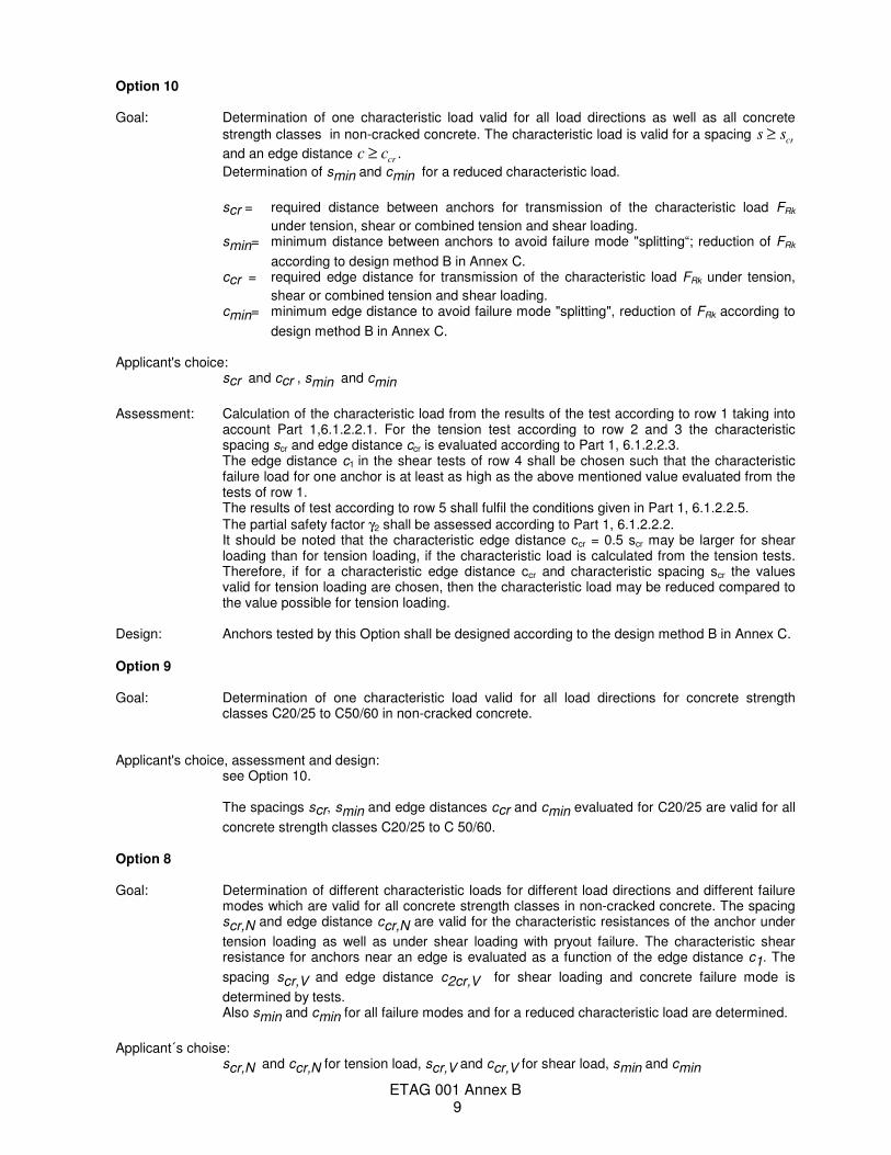
Option 10 Goal: Determination of one characteristic load valid for all load directions as well as all concrete
strength classes in non-cracked concrete. The characteristic load is valid for a spacing s scr≥
and an edge distance c ccr≥ .
Determination of smin and cmin for a reduced characteristic load.
scr = required distance between anchors for transmission of the characteristic load FRk
under tension, shear or combined tension and shear loading. smin= minimum distance between anchors to avoid failure mode "splitting“; reduction of FRk
according to design method B in Annex C. ccr = required edge distance for transmission of the characteristic load FRk under tension,
shear or combined tension and shear loading. cmin= minimum edge distance to avoid failure mode "splitting", reduction of FRk according to
design method B in Annex C. Applicant's choice:
scr and ccr , smin and cmin
Assessment: Calculation of the characteristic load from the results of the test according to row 1 taking into account Part 1,6.1.2.2.1. For the tension test according to row 2 and 3 the characteristic spacing scr and edge distance ccr is evaluated according to Part 1, 6.1.2.2.3. The edge distance c1 in the shear tests of row 4 shall be chosen such that the characteristic failure load for one anchor is at least as high as the above mentioned value evaluated from the tests of row 1.
The results of test according to row 5 shall fulfil the conditions given in Part 1, 6.1.2.2.5.
The partial safety factor γ2 shall be assessed according to Part 1, 6.1.2.2.2. It should be noted that the characteristic edge distance ccr = 0.5 scr may be larger for shear
loading than for tension loading, if the characteristic load is calculated from the tension tests. Therefore, if for a characteristic edge distance ccr and characteristic spacing scr the values valid for tension loading are chosen, then the characteristic load may be reduced compared to the value possible for tension loading.
Design: Anchors tested by this Option shall be designed according to the design method B in Annex C. Option 9 Goal: Determination of one characteristic load valid for all load directions for concrete strength
classes C20/25 to C50/60 in non-cracked concrete. Applicant's choice, assessment and design:
see Option 10. The spacings scr, smin and edge distances ccr and cmin evaluated for C20/25 are valid for all
concrete strength classes C20/25 to C 50/60. Option 8 Goal: Determination of different characteristic loads for different load directions and different failure
modes which are valid for all concrete strength classes in non-cracked concrete. The spacing scr,N and edge distance ccr,N are valid for the characteristic resistances of the anchor under
tension loading as well as under shear loading with pryout failure. The characteristic shear resistance for anchors near an edge is evaluated as a function of the edge distance c1. The
spacing scr,V and edge distance c2cr,V for shear loading and concrete failure mode is
determined by tests. Also smin and cmin for all failure modes and for a reduced characteristic load are determined.
Applicant´s choise:
scr,N and ccr,N for tension load, scr,V and ccr,V for shear load, smin and cmin
ETAG 001 Annex B 10
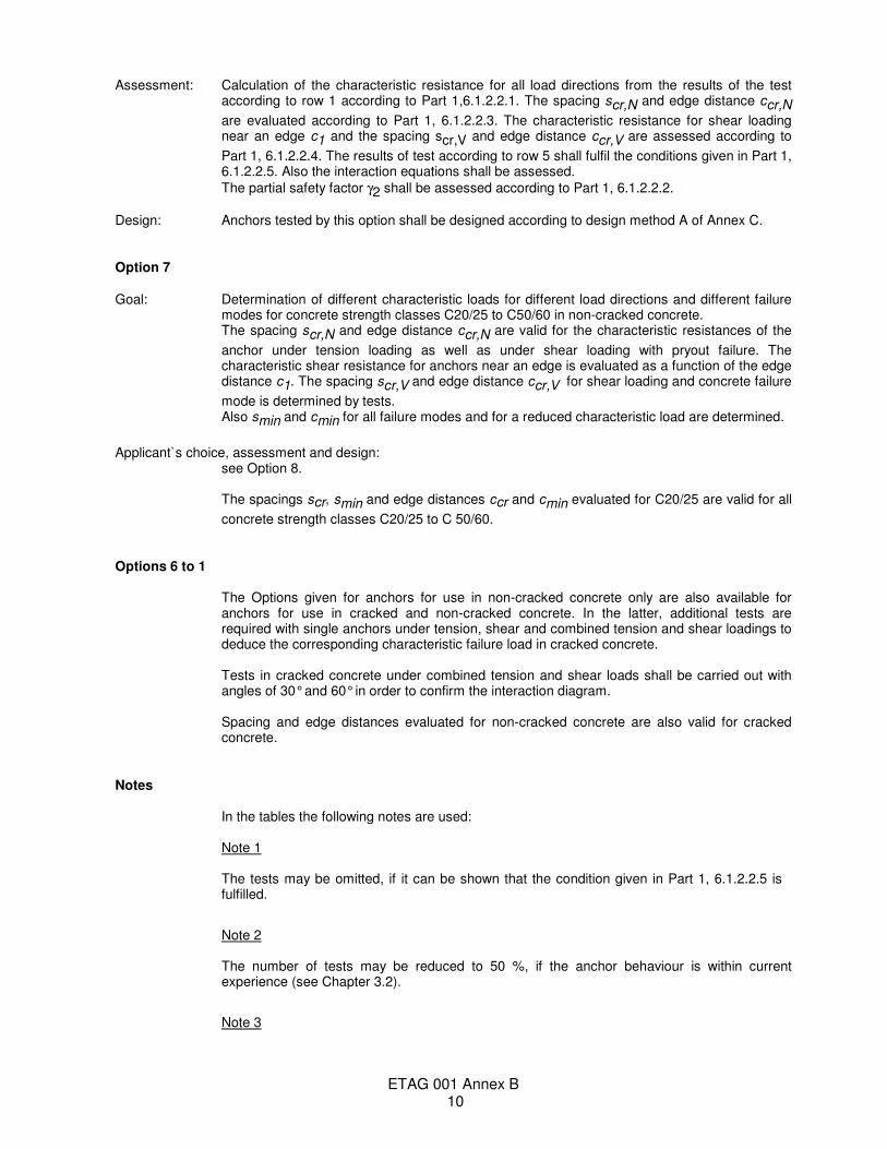
Assessment: Calculation of the characteristic resistance for all load directions from the results of the test according to row 1 according to Part 1,6.1.2.2.1. The spacing scr,N and edge distance ccr,N
are evaluated according to Part 1, 6.1.2.2.3. The characteristic resistance for shear loading near an edge c1 and the spacing scr,V and edge distance ccr,V are assessed according to
Part 1, 6.1.2.2.4. The results of test according to row 5 shall fulfil the conditions given in Part 1, 6.1.2.2.5. Also the interaction equations shall be assessed.
The partial safety factor γ2 shall be assessed according to Part 1, 6.1.2.2.2.
Design: Anchors tested by this option shall be designed according to design method A of Annex C. Option 7 Goal: Determination of different characteristic loads for different load directions and different failure
modes for concrete strength classes C20/25 to C50/60 in non-cracked concrete. The spacing scr,N and edge distance ccr,N are valid for the characteristic resistances of the
anchor under tension loading as well as under shear loading with pryout failure. The characteristic shear resistance for anchors near an edge is evaluated as a function of the edge distance c1. The spacing scr,V and edge distance ccr,V for shear loading and concrete failure
mode is determined by tests. Also smin and cmin for all failure modes and for a reduced characteristic load are determined.
Applicant`s choice, assessment and design: see Option 8. The spacings scr, smin and edge distances ccr and cmin evaluated for C20/25 are valid for all
concrete strength classes C20/25 to C 50/60. Options 6 to 1 The Options given for anchors for use in non-cracked concrete only are also available for
anchors for use in cracked and non-cracked concrete. In the latter, additional tests are required with single anchors under tension, shear and combined tension and shear loadings to deduce the corresponding characteristic failure load in cracked concrete.
Tests in cracked concrete under combined tension and shear loads shall be carried out with
angles of 30° and 60° in order to confirm the interaction diagram. Spacing and edge distances evaluated for non-cracked concrete are also valid for cracked
concrete. Notes In the tables the following notes are used:
Note 1
The tests may be omitted, if it can be shown that the condition given in Part 1, 6.1.2.2.5 is fulfilled.
Note 2 The number of tests may be reduced to 50 %, if the anchor behaviour is within current
experience (see Chapter 3.2).
Note 3
ETAG 001 Annex B 11
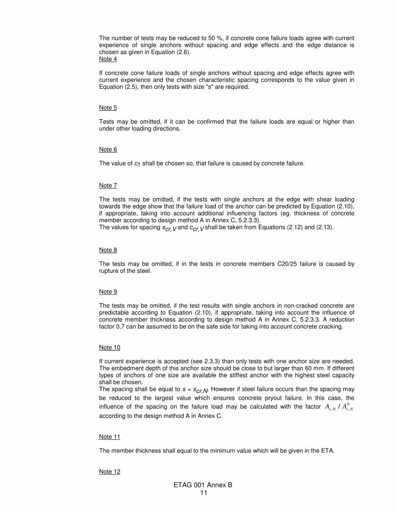
The number of tests may be reduced to 50 %, if concrete cone failure loads agree with current experience of single anchors without spacing and edge effects and the edge distance is chosen as given in Equation (2.6).
Note 4 If concrete cone failure loads of single anchors without spacing and edge effects agree with
current experience and the chosen characteristic spacing corresponds to the value given in Equation (2.5), then only tests with size "s" are required.
Note 5 Tests may be omitted, if it can be confirmed that the failure loads are equal or higher than
under other loading directions. Note 6 The value of c1 shall be chosen so, that failure is caused by concrete failure.
Note 7 The tests may be omitted, if the tests with single anchors at the edge with shear loading
towards the edge show that the failure load of the anchor can be predicted by Equation (2.10), if appropriate, taking into account additional influencing factors (eg. thickness of concrete member according to design method A in Annex C, 5.2.3.3).
The values for spacing scr,V and ccr,V shall be taken from Equations (2.12) and (2.13).
Note 8 The tests may be omitted, if in the tests in concrete members C20/25 failure is caused by
rupture of the steel. Note 9
The tests may be omitted, if the test results with single anchors in non-cracked concrete are predictable according to Equation (2.10), if appropriate, taking into account the influence of concrete member thickness according to design method A in Annex C, 5.2.3.3. A reduction factor 0,7 can be assumed to be on the safe side for taking into account concrete cracking.
Note 10 If current experience is accepted (see 2.3.3) than only tests with one anchor size are needed.
The embedment depth of this anchor size should be close to but larger than 60 mm. If different types of anchors of one size are available the stiffest anchor with the highest steel capacity shall be chosen.
The spacing shall be equal to s = scr,N. However if steel failure occurs than the spacing may
be reduced to the largest value which ensures concrete pryout failure. In this case, the
influence of the spacing on the failure load may be calculated with the factor A Ac N c N, ,/
0
according to the design method A in Annex C. Note 11 The member thickness shall equal to the minimum value which will be given in the ETA. Note 12
ETAG 001 Annex B 12
The member thickness may be larger than the minimum value which will be given in the ETA.
Note 13 This test series with at least 5 tests per sizes is required only if the anchor has a significantly
reduced section along the length of the bolt or the sleeve of a sleeve type anchor should be considered or for internal threaded parts.
Note 14 5 tests per sizes are sufficient if a model for all anchor sizes for splitting failure is used
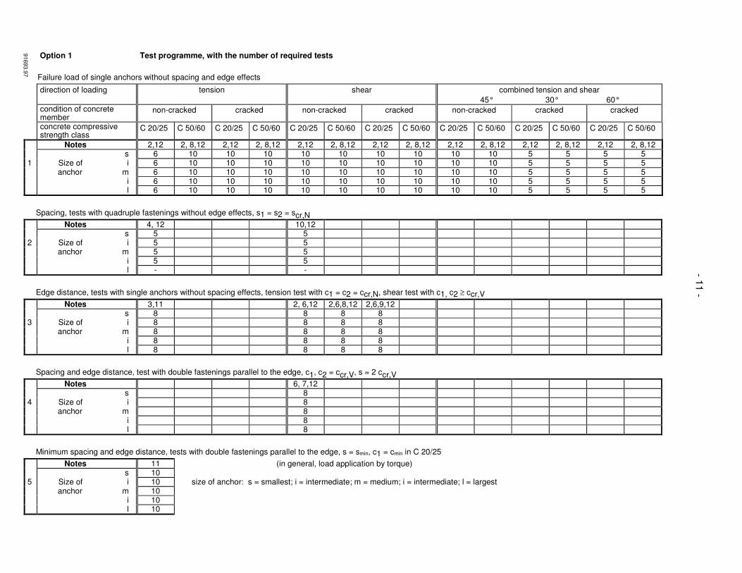
Option 1 Test programme, with the number of required tests
Failure load of single anchors without spacing and edge effects
direction of loading tension shear combined tension and shear
45° 30° 60° condition of concrete
member non-cracked cracked non-cracked cracked non-cracked cracked cracked
concrete compressive strength class
C 20/25 C 50/60 C 20/25 C 50/60 C 20/25 C 50/60 C 20/25 C 50/60 C 20/25 C 50/60 C 20/25 C 50/60 C 20/25 C 50/60
Notes 2,12 2, 8,12 2,12 2, 8,12 2,12 2, 8,12 2,12 2, 8,12 2,12 2, 8,12 2,12 2, 8,12 2,12 2, 8,12 s 6 10 10 10 10 10 10 10 10 10 5 5 5 5 1 Size of i 6 10 10 10 10 10 10 10 10 10 5 5 5 5 anchor m 6 10 10 10 10 10 10 10 10 10 5 5 5 5 i 6 10 10 10 10 10 10 10 10 10 5 5 5 5 l 6 10 10 10 10 10 10 10 10 10 5 5 5 5
Spacing, tests with quadruple fastenings without edge effects, s1 = s2 = scr,N
Notes 4, 12 10,12 s 5 5 2 Size of i 5 5 anchor m 5 5 i 5 5 l - -
Edge distance, tests with single anchors without spacing effects, tension test with c1 = c2 = ccr,N, shear test with c1, c2 ≥ ccr,V
Notes 3,11 2, 6,12 2,6,8,12 2,6,9,12 s 8 8 8 8 3 Size of i 8 8 8 8 anchor m 8 8 8 8 i 8 8 8 8 l 8 8 8 8
Spacing and edge distance, test with double fastenings parallel to the edge, c1, c2 = ccr,V, s = 2 ccr,V
Notes 6, 7,12 s 8 4 Size of i 8 anchor m 8 i 8 l 8
Minimum spacing and edge distance, tests with double fastenings parallel to the edge, s = smin, c1 = cmin in C 20/25
Notes 11 (in general, load application by torque) s 10 5 Size of i 10 size of anchor: s = smallest; i = intermediate; m = medium; i = intermediate; l = largest anchor m 10 i 10 l 10
91693.9
7
- 11 -
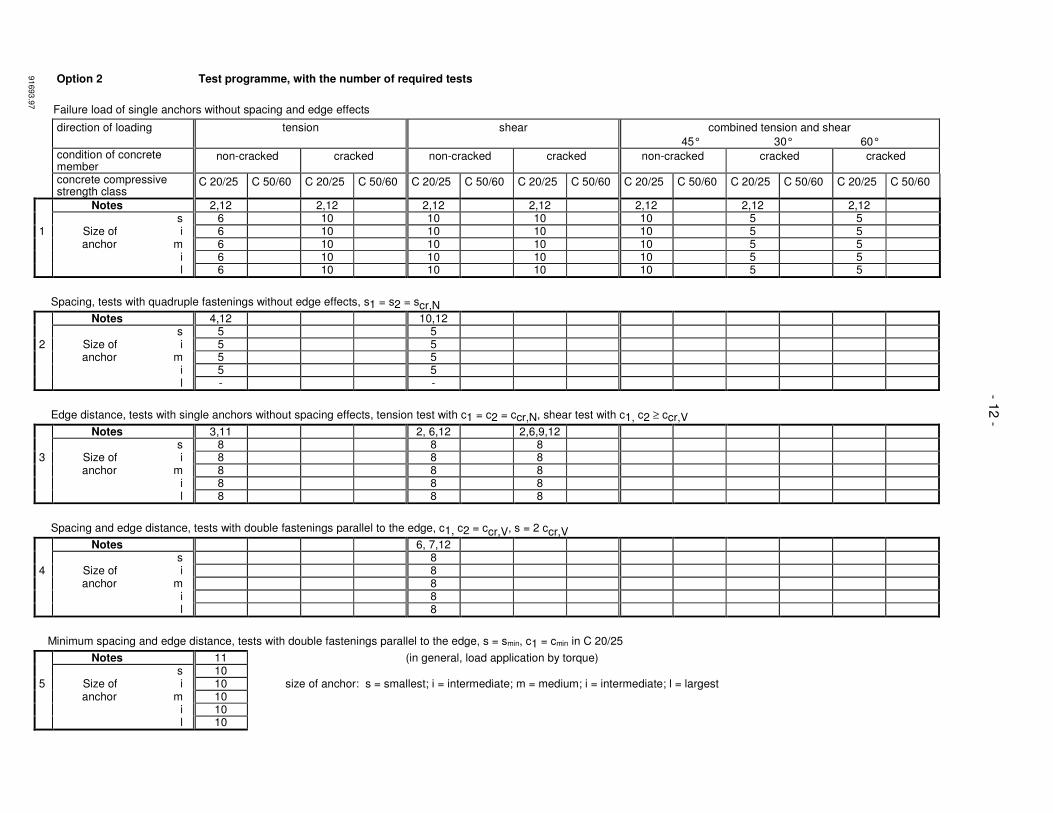
Option 2 Test programme, with the number of required tests
Failure load of single anchors without spacing and edge effects
direction of loading tension shear combined tension and shear
45° 30° 60° condition of concrete
member non-cracked cracked non-cracked cracked non-cracked cracked cracked
concrete compressive strength class
C 20/25 C 50/60 C 20/25 C 50/60 C 20/25 C 50/60 C 20/25 C 50/60 C 20/25 C 50/60 C 20/25 C 50/60 C 20/25 C 50/60
Notes 2,12 2,12 2,12 2,12 2,12 2,12 2,12 s 6 10 10 10 10 5 5 1 Size of i 6 10 10 10 10 5 5 anchor m 6 10 10 10 10 5 5 i 6 10 10 10 10 5 5 l 6 10 10 10 10 5 5
Spacing, tests with quadruple fastenings without edge effects, s1 = s2 = scr,N
Notes 4,12 10,12 s 5 5 2 Size of i 5 5 anchor m 5 5 i 5 5 l - -
Edge distance, tests with single anchors without spacing effects, tension test with c1 = c2 = ccr,N, shear test with c1, c2 ≥ ccr,V
Notes 3,11 2, 6,12 2,6,9,12 s 8 8 8 3 Size of i 8 8 8 anchor m 8 8 8 i 8 8 8 l 8 8 8
Spacing and edge distance, tests with double fastenings parallel to the edge, c1, c2 = ccr,V, s = 2 ccr,V
Notes 6, 7,12 s 8 4 Size of i 8 anchor m 8 i 8 l 8
Minimum spacing and edge distance, tests with double fastenings parallel to the edge, s = smin, c1 = cmin in C 20/25
Notes 11 (in general, load application by torque) s 10 5 Size of i 10 size of anchor: s = smallest; i = intermediate; m = medium; i = intermediate; l = largest anchor m 10 i 10 l 10
91693.9
7
- 12 -
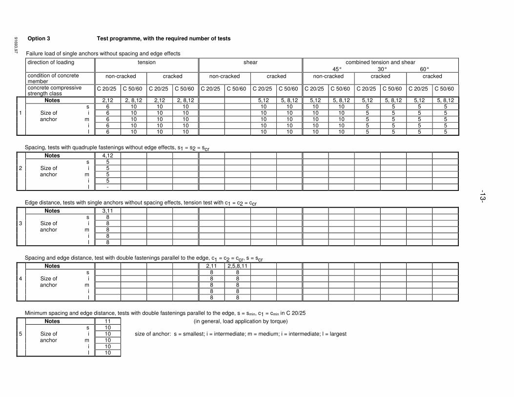
Option 3 Test programme, with the required number of tests
Failure load of single anchors without spacing and edge effects
direction of loading tension shear combined tension and shear
45° 30° 60° condition of concrete
member non-cracked cracked non-cracked cracked non-cracked cracked cracked
concrete compressive strength class
C 20/25 C 50/60 C 20/25 C 50/60 C 20/25 C 50/60 C 20/25 C 50/60 C 20/25 C 50/60 C 20/25 C 50/60 C 20/25 C 50/60
Notes 2,12 2, 8,12 2,12 2, 8,12 5,12 5, 8,12 5,12 5, 8,12 5,12 5, 8,12 5,12 5, 8,12 s 6 10 10 10 10 10 10 10 5 5 5 5 1 Size of i 6 10 10 10 10 10 10 10 5 5 5 5 anchor m 6 10 10 10 10 10 10 10 5 5 5 5 i 6 10 10 10 10 10 10 10 5 5 5 5 l 6 10 10 10 10 10 10 10 5 5 5 5
Spacing, tests with quadruple fastenings without edge effects, s1 = s2 = scr
Notes 4,12 s 5 2 Size of i 5 anchor m 5 i 5 l -
Edge distance, tests with single anchors without spacing effects, tension test with c1 = c2 = ccr
Notes 3,11 s 8 3 Size of i 8 anchor m 8 i 8 l 8
Spacing and edge distance, test with double fastenings parallel to the edge, c1 = c2 = ccr, s = scr
Notes 2,11 2,5,8,11 s 8 8 4 Size of i 8 8 anchor m 8 8 i 8 8 l 8 8
Minimum spacing and edge distance, tests with double fastenings parallel to the edge, s = smin, c1 = cmin in C 20/25
Notes 11 (in general, load application by torque) s 10 5 Size of i 10 size of anchor: s = smallest; i = intermediate; m = medium; i = intermediate; l = largest anchor m 10 i 10 l 10
-13
-
91693.9
7

Option 4 Test programme, with the required number of tests
Failure load of single anchors without spacing and edge effects
direction of loading tension shear combined tension and shear
45° 30° 60° condition of concrete
member non-cracked cracked non-cracked cracked non-cracked cracked cracked
concrete compressive strength class
C 20/25 C 50/60 C 20/25 C 50/60 C 20/25 C 50/60 C 20/25 C 50/60 C 20/25 C 50/60 C 20/25 C 50/60 C 20/25 C 50/60
Notes 2,12 2,12 5,12 5,12 5,12 5,12 s 6 10 10 10 5 5 1 Size of i 6 10 10 10 5 5 anchor m 6 10 10 10 5 5 i 6 10 10 10 5 5 l 6 10 10 10 5 5
Spacing, tests with quadruple fastenings without edge effects, s1 = s2 = scr
Notes 4,12 s 5 2 Size of i 5 anchor m 5 i 5 l -
Edge distance, tests with single anchors without spacing effects, tension test with c1 = c2 = ccr
Notes 3,11 s 8 3 Size of i 8 anchor m 8 i 8 l 8
Spacing and edge distance, tests with double fastenings parallel to the edge, c1 = c2 = ccr, s = scr
Notes 2,11 s 8 4 Size of i 8 anchor m 8 i 8 l 8
Minimum spacing and edge distance, tests with double fastenings parallel to the edge, s = smin, c1 = cmin in C 20/25
Notes 11 (in general, load application by torque) s 10 5 Size of i 10 size of anchor: s = smallest; i = intermediate; m = medium; i = intermediate; l = largest anchor m 10 i 10 l 10
-14
-
91693.9
7
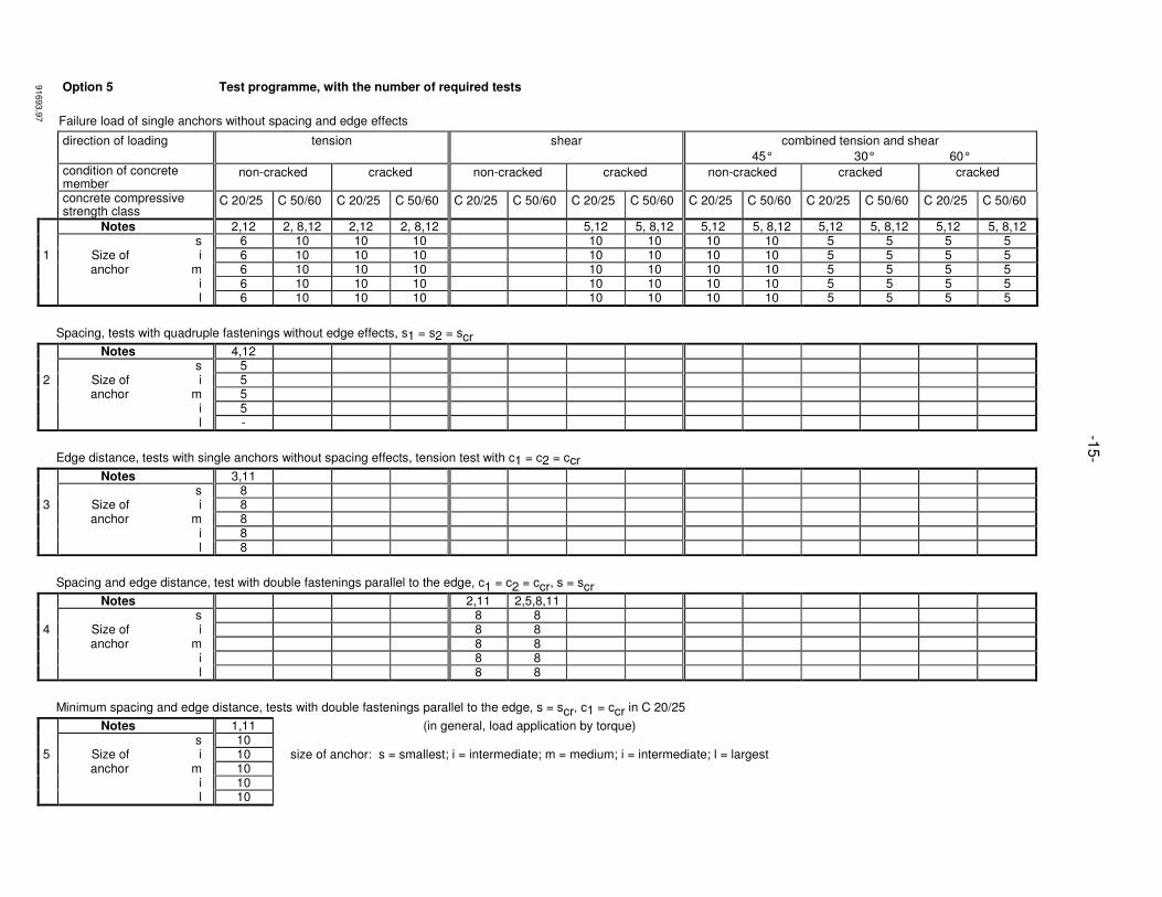
Option 5 Test programme, with the number of required tests
Failure load of single anchors without spacing and edge effects
direction of loading tension shear combined tension and shear
45° 30° 60° condition of concrete
member non-cracked cracked non-cracked cracked non-cracked cracked cracked
concrete compressive strength class
C 20/25 C 50/60 C 20/25 C 50/60 C 20/25 C 50/60 C 20/25 C 50/60 C 20/25 C 50/60 C 20/25 C 50/60 C 20/25 C 50/60
Notes 2,12 2, 8,12 2,12 2, 8,12 5,12 5, 8,12 5,12 5, 8,12 5,12 5, 8,12 5,12 5, 8,12 s 6 10 10 10 10 10 10 10 5 5 5 5 1 Size of i 6 10 10 10 10 10 10 10 5 5 5 5 anchor m 6 10 10 10 10 10 10 10 5 5 5 5 i 6 10 10 10 10 10 10 10 5 5 5 5 l 6 10 10 10 10 10 10 10 5 5 5 5
Spacing, tests with quadruple fastenings without edge effects, s1 = s2 = scr
Notes 4,12 s 5 2 Size of i 5 anchor m 5 i 5 l -
Edge distance, tests with single anchors without spacing effects, tension test with c1 = c2 = ccr
Notes 3,11 s 8 3 Size of i 8 anchor m 8 i 8 l 8
Spacing and edge distance, test with double fastenings parallel to the edge, c1 = c2 = ccr, s = scr
Notes 2,11 2,5,8,11 s 8 8 4 Size of i 8 8 anchor m 8 8 i 8 8 l 8 8
Minimum spacing and edge distance, tests with double fastenings parallel to the edge, s = scr, c1 = ccr in C 20/25
Notes 1,11 (in general, load application by torque) s 10 5 Size of i 10 size of anchor: s = smallest; i = intermediate; m = medium; i = intermediate; l = largest anchor m 10 i 10 l 10
-15
-
91693.9
7
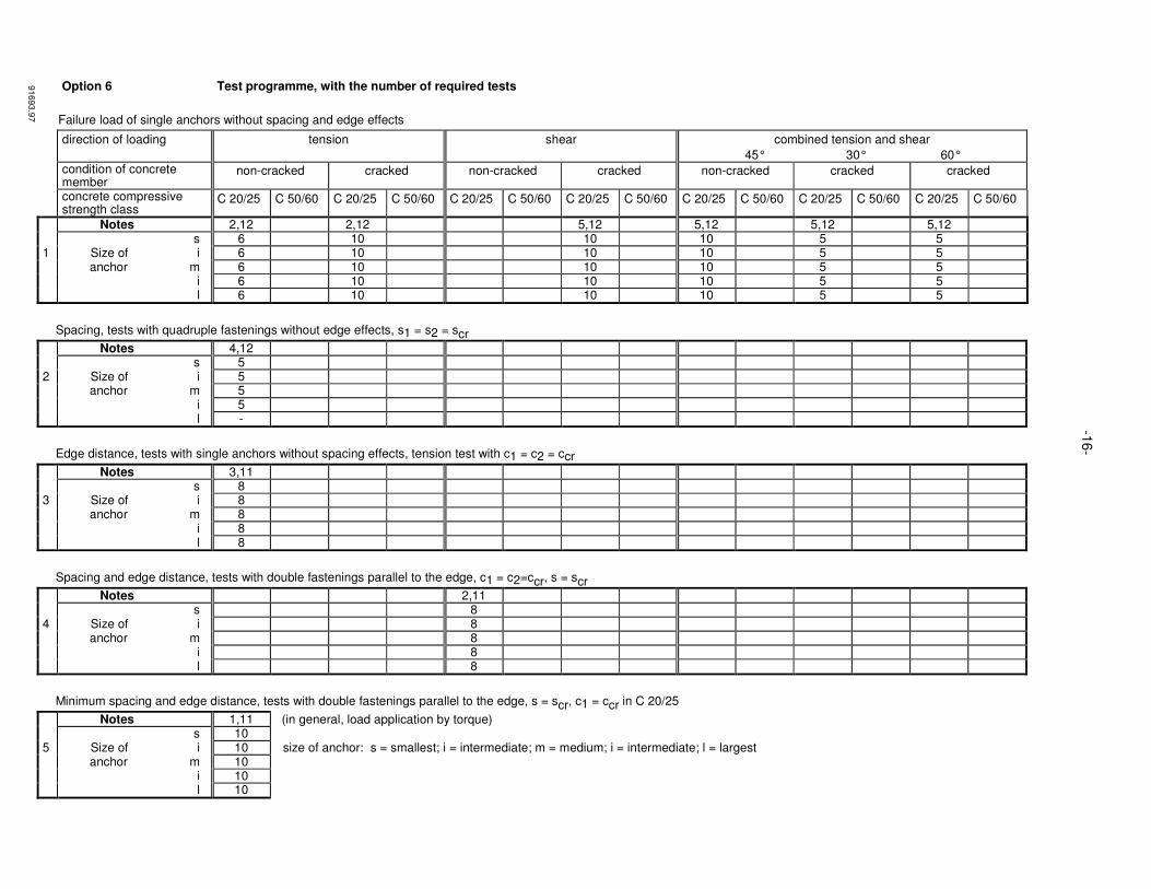
Option 6 Test programme, with the number of required tests
Failure load of single anchors without spacing and edge effects
direction of loading tension shear combined tension and shear
45° 30° 60° condition of concrete
member non-cracked cracked non-cracked cracked non-cracked cracked cracked
concrete compressive strength class
C 20/25 C 50/60 C 20/25 C 50/60 C 20/25 C 50/60 C 20/25 C 50/60 C 20/25 C 50/60 C 20/25 C 50/60 C 20/25 C 50/60
Notes 2,12 2,12 5,12 5,12 5,12 5,12 s 6 10 10 10 5 5 1 Size of i 6 10 10 10 5 5 anchor m 6 10 10 10 5 5 i 6 10 10 10 5 5 l 6 10 10 10 5 5
Spacing, tests with quadruple fastenings without edge effects, s1 = s2 = scr
Notes 4,12 s 5 2 Size of i 5 anchor m 5 i 5 l -
Edge distance, tests with single anchors without spacing effects, tension test with c1 = c2 = ccr
Notes 3,11 s 8 3 Size of i 8 anchor m 8 i 8 l 8
Spacing and edge distance, tests with double fastenings parallel to the edge, c1 = c2=ccr, s = scr
Notes 2,11 s 8 4 Size of i 8 anchor m 8 i 8 l 8
Minimum spacing and edge distance, tests with double fastenings parallel to the edge, s = scr, c1 = ccr in C 20/25
Notes 1,11 (in general, load application by torque) s 10 5 Size of i 10 size of anchor: s = smallest; i = intermediate; m = medium; i = intermediate; l = largest anchor m 10 i 10 l 10
-16-
91693.9
7
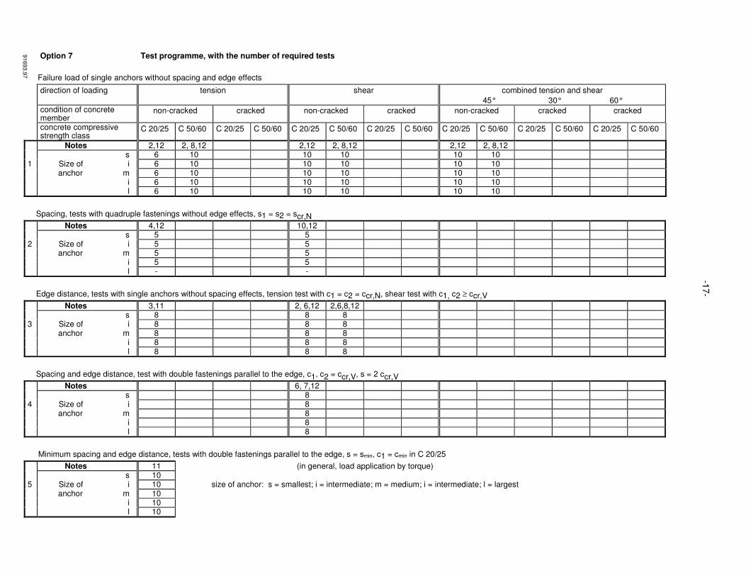
Option 7 Test programme, with the number of required tests
Failure load of single anchors without spacing and edge effects
direction of loading tension shear combined tension and shear
45° 30° 60° condition of concrete
member non-cracked cracked non-cracked cracked non-cracked cracked cracked
concrete compressive strength class
C 20/25 C 50/60 C 20/25 C 50/60 C 20/25 C 50/60 C 20/25 C 50/60 C 20/25 C 50/60 C 20/25 C 50/60 C 20/25 C 50/60
Notes 2,12 2, 8,12 2,12 2, 8,12 2,12 2, 8,12 s 6 10 10 10 10 10 1 Size of i 6 10 10 10 10 10 anchor m 6 10 10 10 10 10 i 6 10 10 10 10 10 l 6 10 10 10 10 10
Spacing, tests with quadruple fastenings without edge effects, s1 = s2 = scr,N
Notes 4,12 10,12 s 5 5 2 Size of i 5 5 anchor m 5 5 i 5 5 l - -
Edge distance, tests with single anchors without spacing effects, tension test with c1 = c2 = ccr,N, shear test with c1, c2 ≥ ccr,V
Notes 3,11 2, 6,12 2,6,8,12 s 8 8 8 3 Size of i 8 8 8 anchor m 8 8 8 i 8 8 8 l 8 8 8
Spacing and edge distance, test with double fastenings parallel to the edge, c1, c2 = ccr,V, s = 2 ccr,V
Notes 6, 7,12 s 8 4 Size of i 8 anchor m 8 i 8 l 8
Minimum spacing and edge distance, tests with double fastenings parallel to the edge, s = smin, c1 = cmin in C 20/25
Notes 11 (in general, load application by torque) s 10 5 Size of i 10 size of anchor: s = smallest; i = intermediate; m = medium; i = intermediate; l = largest anchor m 10 i 10 l 10
-17-
91693.9
7
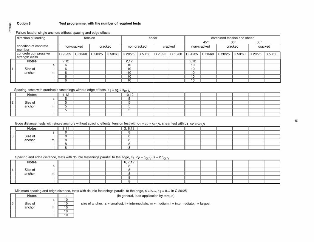
Option 8 Test programme, with the number of required tests
Failure load of single anchors without spacing and edge effects
direction of loading tension shear combined tension and shear
45° 30° 60° condition of concrete
member non-cracked cracked non-cracked cracked non-cracked cracked cracked
concrete compressive strength class
C 20/25 C 50/60 C 20/25 C 50/60 C 20/25 C 50/60 C 20/25 C 50/60 C 20/25 C 50/60 C 20/25 C 50/60 C 20/25 C 50/60
Notes 2,12 2,12 2,12 s 6 10 10 1 Size of i 6 10 10 anchor m 6 10 10 i 6 10 10 l 6 10 10
Spacing, tests with quadruple fastenings without edge effects, s1 = s2 = scr,N
Notes 4,12 10,12 s 5 5 2 Size of i 5 5 anchor m 5 5 i 5 5 l - -
Edge distance, tests with single anchors without spacing effects, tension test with c1 = c2 = ccr,N, shear test with c1, c2 ≥ ccr,V
Notes 3,11 2, 6,12 s 8 8 3 Size of i 8 8 anchor m 8 8 i 8 8 l 8 8
Spacing and edge distance, tests with double fastenings parallel to the edge, c1, c2 = ccr,V, s = 2 ccr;V
Notes 6, 7,12 s 8 4 Size of i 8 anchor m 8 i 8 l 8
Minimum spacing and edge distance, tests with double fastenings parallel to the edge, s = smin, c1 = cmin in C 20/25
Notes 11 (in general, load application by torque) s 10 5 Size of i 10 size of anchor: s = smallest; i = intermediate; m = medium; i = intermediate; l = largest anchor m 10 i 10 l 10
-18
-
91693.9
7

Option 9 Test programme, with the number of required tests
Failure load of single anchors without spacing and edge effects
direction of loading tension shear combined tension and shear
45° 30° 60° condition of concrete
member non-cracked cracked non-cracked cracked non-cracked cracked cracked
concrete compressive strength class
C 20/25 C 50/60 C 20/25 C 50/60 C 20/25 C 50/60 C 20/25 C 50/60 C 20/25 C 50/60 C 20/25 C 50/60 C 20/25 C 50/60
Notes 2,12 2, 8,12 5,12 5, 8,12 s 6 10 10 10 1 Size of i 6 10 10 10 anchor m 6 10 10 10 i 6 10 10 10 l 6 10 10 10
Spacing, tests with quadruple fastenings without edge effects, s1 = s2 = scr
Notes 4,12 s 5 2 Size of i 5 anchor m 5 i 5 l -
Edge distance, tests with single anchors without spacing effects, tension test with c1 = c2 = ccr
Notes 3,11 s 8 3 Size of i 8 anchor m 8 i 8 l 8
Spacing and edge distance, test with double fastenings parallel to the edge, c1 = c2 = ccr, s = scr
Notes 2,11 2,5,8,11 s 8 8 4 Size of i 8 8 anchor m 8 8 i 8 8 l 8 8
Minimum spacing and edge distance, tests with double fastenings parallel to the edge, s = smin, c1 = cmin in C 20/25
Notes 11 (in general, load application by torque) s 10 5 Size of i 10 size of anchor: s = smallest; i = intermediate; m = medium; i = intermediate; l = largest anchor m 10 i 10 l 10
-19
-
91693.9
7
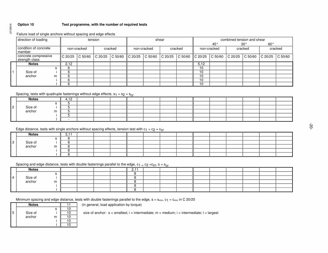
Option 10 Test programme, with the number of required tests
Failure load of single anchors without spacing and edge effects
direction of loading tension shear combined tension and shear
45° 30° 60° condition of concrete
member non-cracked cracked non-cracked cracked non-cracked cracked cracked
concrete compressive strength class
C 20/25 C 50/60 C 20/25 C 50/60 C 20/25 C 50/60 C 20/25 C 50/60 C 20/25 C 50/60 C 20/25 C 50/60 C 20/25 C 50/60
Notes 2,12 5,12 s 6 10 1 Size of i 6 10 anchor m 6 10 i 6 10 l 6 10
Spacing, tests with quadruple fastenings without edge effects, s1 = s2 = scr
Notes 4,12 s 5 2 Size of i 5 anchor m 5 i 5 l -
Edge distance, tests with single anchors without spacing effects, tension test with c1 = c2 = ccr
Notes 3,11 s 8 3 Size of i 8 anchor m 8 i 8 l 8
Spacing and edge distance, tests with double fastenings parallel to the edge, c1 = c2 =ccr, s = scr
Notes 2,11 s 8 4 Size of i 8 anchor m 8 i 8 l 8
Minimum spacing and edge distance, tests with double fastenings parallel to the edge, s = smin, c1 = cmin in C 20/25
Notes 11 (in general, load application by torque) s 10 5 Size of i 10 size of anchor: s = smallest; i = intermediate; m = medium; i = intermediate; l = largest anchor m 10 i 10 l 10
-20-
91693.9
7
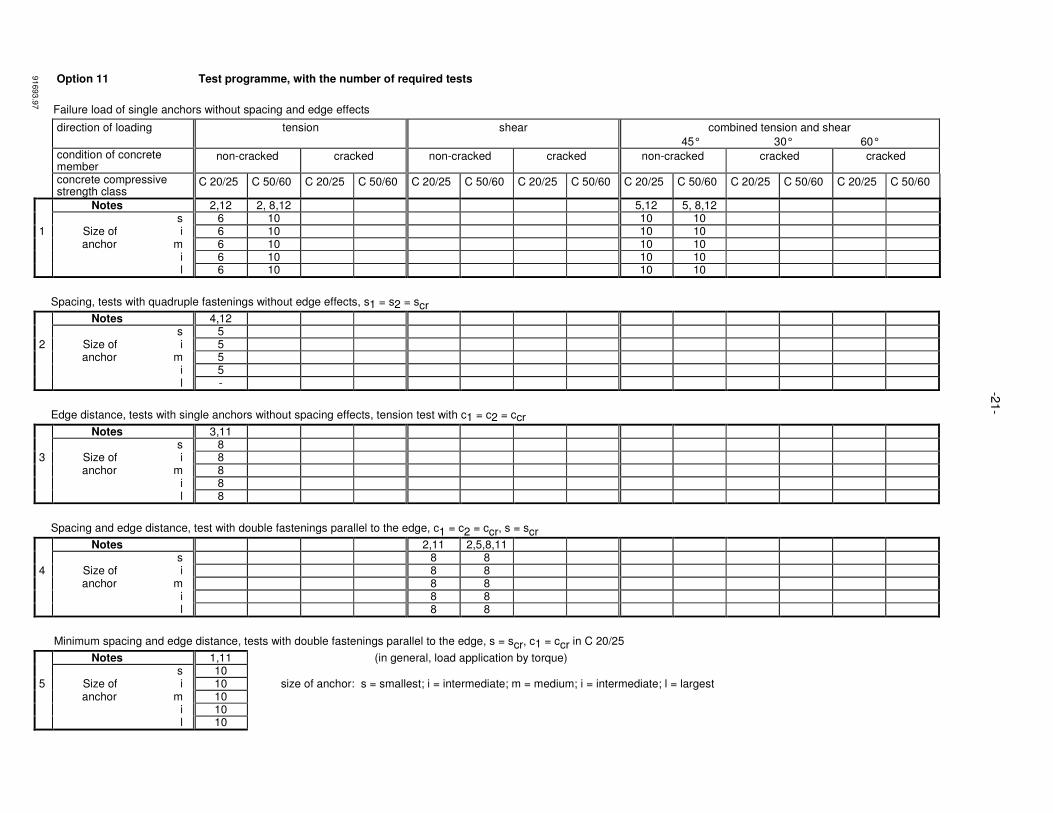
Option 11 Test programme, with the number of required tests
Failure load of single anchors without spacing and edge effects
direction of loading tension shear combined tension and shear
45° 30° 60° condition of concrete
member non-cracked cracked non-cracked cracked non-cracked cracked cracked
concrete compressive strength class
C 20/25 C 50/60 C 20/25 C 50/60 C 20/25 C 50/60 C 20/25 C 50/60 C 20/25 C 50/60 C 20/25 C 50/60 C 20/25 C 50/60
Notes 2,12 2, 8,12 5,12 5, 8,12 s 6 10 10 10 1 Size of i 6 10 10 10 anchor m 6 10 10 10 i 6 10 10 10 l 6 10 10 10
Spacing, tests with quadruple fastenings without edge effects, s1 = s2 = scr
Notes 4,12 s 5 2 Size of i 5 anchor m 5 i 5 l -
Edge distance, tests with single anchors without spacing effects, tension test with c1 = c2 = ccr
Notes 3,11 s 8 3 Size of i 8 anchor m 8 i 8 l 8
Spacing and edge distance, test with double fastenings parallel to the edge, c1 = c2 = ccr, s = scr
Notes 2,11 2,5,8,11 s 8 8 4 Size of i 8 8 anchor m 8 8 i 8 8 l 8 8
Minimum spacing and edge distance, tests with double fastenings parallel to the edge, s = scr, c1 = ccr in C 20/25
Notes 1,11 (in general, load application by torque) s 10 5 Size of i 10 size of anchor: s = smallest; i = intermediate; m = medium; i = intermediate; l = largest anchor m 10 i 10 l 10
-21
-
91693.9
7
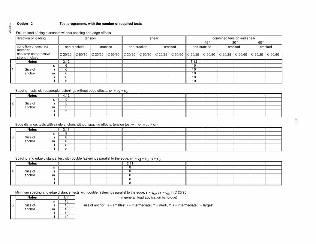
Option 12 Test programme, with the number of required tests
Failure load of single anchors without spacing and edge effects
direction of loading tension shear combined tension and shear
45° 30° 60° condition of concrete
member non-cracked cracked non-cracked cracked non-cracked cracked cracked
concrete compressive strength class
C 20/25 C 50/60 C 20/25 C 50/60 C 20/25 C 50/60 C 20/25 C 50/60 C 20/25 C 50/60 C 20/25 C 50/60 C 20/25 C 50/60
Notes 2,12 5,12 s 6 10 1 Size of i 6 10 anchor m 6 10 i 6 10 l 6 10
Spacing, tests with quadruple fastenings without edge effects, s1 = s2 = scr
Notes 4,12 s 5 2 Size of i 5 anchor m 5 i 5 l -
Edge distance, tests with single anchors without spacing effects, tension test with c1 = c2 = ccr
Notes 3,11 s 8 3 Size of i 8 anchor m 8 i 8 l 8
Spacing and edge distance, test with double fastenings parallel to the edge, c1 = c2 = ccr, s = scr
Notes 2,11 s 8 4 Size of i 8 anchor m 8 i 8 l 8
Minimum spacing and edge distance, tests with double fastenings parallel to the edge, s = scr, c1 = ccr in C 20/25
Notes 1,11 (in general, load application by torque) s 10 5 Size of i 10 size of anchor: s = smallest; i = intermediate; m = medium; i = intermediate; l = largest anchor m 10 i 10 l 10
-22
-
91693.9
7
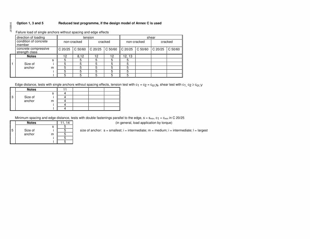
Option 1, 3 and 5 Reduced test programme, if the design model of Annex C is used
Failure load of single anchors without spacing and edge effects
direction of loading tension shear condition of concrete
member non-cracked cracked non-cracked cracked
concrete compressive strength class
C 20/25 C 50/60 C 20/25 C 50/60 C 20/25 C 50/60 C 20/25 C 50/60
Notes 12 8,12 12 12 12, 13 s 5 5 5 5 5 1 Size of i 5 5 5 5 5 anchor m 5 5 5 5 5 i 5 5 5 5 5 l 5 5 5 5 5
Edge distance, tests with single anchors without spacing effects, tension test with c1 = c2 = ccr,N, shear test with c1, c2 ≥ ccr,V
Notes 11 s 4 3 Size of i 4 anchor m 4 i 4 l 4
Minimum spacing and edge distance, tests with double fastenings parallel to the edge, s = smin, c1 = cmin in C 20/25
Notes 11, 14 (in general, load application by torque) s 5 5 Size of i 5 size of anchor: s = smallest; i = intermediate; m = medium; i = intermediate; l = largest anchor m 5 i 5 l 5
91693.9
7

Option 2, 4 and 6 Reduced test programme, if the design model of Annex C is used
Failure load of single anchors without spacing and edge effects
direction of loading tension shear condition of concrete
member non-cracked cracked non-cracked cracked
concrete compressive strength class
C 20/25 C 50/60 C 20/25 C 50/60 C 20/25 C 50/60 C 20/25 C 50/60
Notes 12 12 12, 13 s 5 5 5 1 Size of i 5 5 5 anchor m 5 5 5 i 5 5 5 l 5 5 5
Edge distance, tests with single anchors without spacing effects, tension test with c1 = c2 = ccr,N, shear test with c1, c2 ≥ ccr,V
Notes 11 s 4 3 Size of i 4 anchor m 4 i 4 l 4
Minimum spacing and edge distance, tests with double fastenings parallel to the edge, s = smin, c1 = cmin in C 20/25
Notes 11, 14 (in general, load application by torque) s 5 5 Size of i 5 size of anchor: s = smallest; i = intermediate; m = medium; i = intermediate; l = largest anchor m 5 i 5 l 5
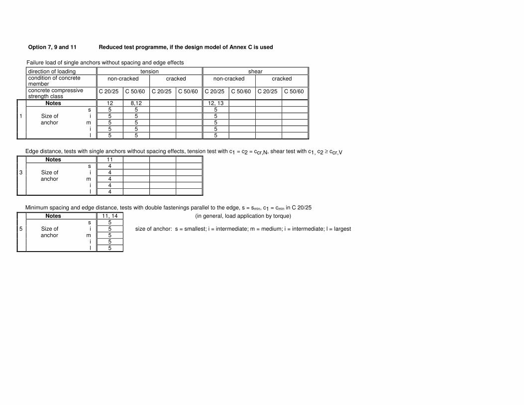
Option 7, 9 and 11 Reduced test programme, if the design model of Annex C is used
Failure load of single anchors without spacing and edge effects
direction of loading tension shear condition of concrete
member non-cracked cracked non-cracked cracked
concrete compressive strength class
C 20/25 C 50/60 C 20/25 C 50/60 C 20/25 C 50/60 C 20/25 C 50/60
Notes 12 8,12 12, 13 s 5 5 5 1 Size of i 5 5 5 anchor m 5 5 5 i 5 5 5 l 5 5 5
Edge distance, tests with single anchors without spacing effects, tension test with c1 = c2 = ccr,N, shear test with c1, c2 ≥ ccr,V
Notes 11 s 4 3 Size of i 4 anchor m 4 i 4 l 4
Minimum spacing and edge distance, tests with double fastenings parallel to the edge, s = smin, c1 = cmin in C 20/25
Notes 11, 14 (in general, load application by torque) s 5 5 Size of i 5 size of anchor: s = smallest; i = intermediate; m = medium; i = intermediate; l = largest anchor m 5 i 5 l 5
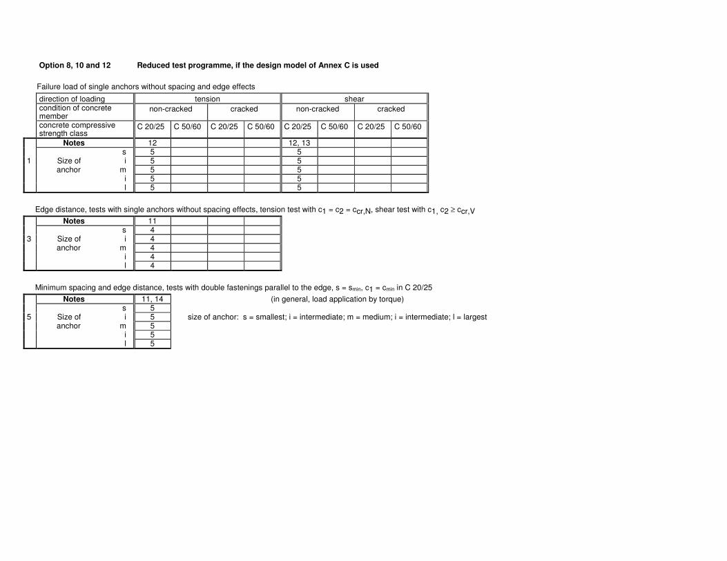
Option 8, 10 and 12 Reduced test programme, if the design model of Annex C is used
Failure load of single anchors without spacing and edge effects
direction of loading tension shear condition of concrete
member non-cracked cracked non-cracked cracked
concrete compressive strength class
C 20/25 C 50/60 C 20/25 C 50/60 C 20/25 C 50/60 C 20/25 C 50/60
Notes 12 12, 13 s 5 5 1 Size of i 5 5 anchor m 5 5 i 5 5 l 5 5
Edge distance, tests with single anchors without spacing effects, tension test with c1 = c2 = ccr,N, shear test with c1, c2 ≥ ccr,V
Notes 11 s 4 3 Size of i 4 anchor m 4 i 4 l 4
Minimum spacing and edge distance, tests with double fastenings parallel to the edge, s = smin, c1 = cmin in C 20/25
Notes 11, 14 (in general, load application by torque) s 5 5 Size of i 5 size of anchor: s = smallest; i = intermediate; m = medium; i = intermediate; l = largest anchor m 5 i 5 l 5