etabs version 17.0.0 release notes - …installs.csiamerica.com/software/etabs/17/release... ·...
TRANSCRIPT

ETABS v17.0.0 ISO# RELETA1700 2018-05-31 Page 1 of 24
ETABS® Version 17.0.0 Release Notes
© Copyright Computers and Structures, Inc., 2018
Notice Date: 2018-05-31
This file lists all changes made to ETABS since the previous version. Most changes do not affect most users. Incidents marked with an asterisk (*) in the first column of the tables below are more significant.
Changes from v16.2.1 (Released 2018-01-10)
Licensing and Installation Enhancements Implemented
* Incident Description
* 201397 The version number of ETABS has been changed to v17.0.0 for a new major release. ETABS v17 is available as a 64-bit version only so as to provide better performance.
Drafting and Meshing Enhancements Implemented
* Incident Description
* 88684 An enhancement has been made to add a general mesher for floor area objects. The generated mesh will primarily consist of quadrilateral elements, with triangles as needed near transitions and discontinuities. The general mesher has less reliance on edge constraints to provide continuity between floor elements. The general mesher is the new default. However, the old rectangular mesher has not been removed so as not to modify results for old models.
206995 An enhancement has been made where Architectural Objects can now be deleted under the command Options > Architectural Plan Options.
* 211489 An enhancement has been made to expand the Edit > Edit Shell > Merge Shells command to merge two or more selected shell objects into a single shell. Previously only two selected shells could be merged at a time. Additionally, a form is now provided to view the merge prior to the operation being performed and select the existing shell from which the new shell will inherit assignments. The following restrictions apply: 1.) Only floor elements can be merged. 2.) Only shells with the same property and located at the same elevation are merged. The new form will group the selected shells by property and elevation, and each group can be viewed in the form by changing the property and elevation. For each group you can choose the shell from which any assignments will be inherited. 3.) If more than two shells are selected in a group, they should not overlap. If only two shells are selected, then the overlap will be removed. 4.) Curved edges are not supported. Instead, they will be converted to multi-segment straight lines.
ETABS v17.0.0 ISO# RELETA1700 2018-05-31 Page 2 of 24
* Incident Description
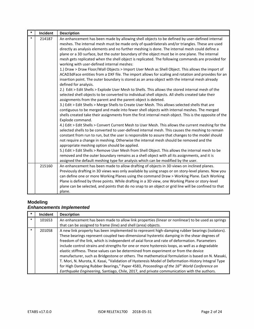
* 214187 An enhancement has been made by allowing shell objects to be defined by user-defined internal meshes. The internal mesh must be made only of quadrilaterals and/or triangles. These are used directly as analysis elements and no further meshing is done. The internal mesh could define a plane or a 3D surface, but the outer boundary of the object must be in one plane. The internal mesh gets replicated when the shell object is replicated. The following commands are provided for working with user-defined internal meshes: 1.) Draw > Draw Floor/Wall Objects > Import User Mesh as Shell Object. This allows the import of ACAD3dFace entities from a DXF file. The import allows for scaling and rotation and provides for an insertion point. The outer boundary is stored as an area object with the internal mesh already defined for analysis. 2.) Edit > Edit Shells > Explode User Mesh to Shells. This allows the stored internal mesh of the selected shell objects to be converted to individual shell objects. All shells created take their assignments from the parent and the parent object is deleted. 3.) Edit > Edit Shells > Merge Shells to Create User Mesh. This allows selected shells that are contiguous to be merged and made into fewer shell objects with internal meshes. The merged shells created take their assignments from the first internal mesh object. This is the opposite of the Explode command. 4.) Edit > Edit Shells > Convert Current Mesh to User Mesh. This allows the current meshing for the selected shells to be converted to user-defined internal mesh. This causes the meshing to remain constant from run to run, but the user is responsible to assure that changes to the model should not require a change in meshing. Otherwise the internal mesh should be removed and the appropriate meshing option should be applied. 5.) Edit > Edit Shells > Remove User Mesh from Shell Object. This allows the internal mesh to be removed and the outer boundary remains as a shell object with all its assignments, and it is assigned the default meshing type for analysis which can be modified by the user.
215160 An enhancement has been made to allow drafting of objects in 3D views on inclined planes. Previously drafting in 3D views was only available by using snaps or on story-level planes. Now you can define one or more Working Planes using the command Draw > Working Plane. Each Working Plane is defined by three points. While drafting in a 3D view, one Working Plane or story-level plane can be selected, and points that do no snap to an object or grid line will be confined to that plane.
Modeling Enhancements Implemented
* Incident Description
* 101653 An enhancement has been made to allow link properties (linear or nonlinear) to be used as springs that can be assigned to frame (line) and shell (area) objects.
* 201058 A new link property has been implemented to represent high-damping rubber bearings (isolators). These bearings represent coupled two-dimensional hysteretic damping in the shear degrees of freedom of the link, which is independent of axial force and rate of deformation. Parameters include control strains and strengths for one or more hysteresis loops, as well as a degradable elastic stiffness. These values can be determined from experiment or from the device manufacturer, such as Bridgestone or others. The mathematical formulation is based on N. Masaki, T. Mori, N. Murota, K. Kasai, “Validation of Hysteresis Model of Deformation-History Integral Type for High Damping Rubber Bearings,” Paper 4583, Proceedings of the 16th World Conference on Earthquake Engineering, Santiago, Chile, 2017, and private communication with the authors.

ETABS v17.0.0 ISO# RELETA1700 2018-05-31 Page 3 of 24
* Incident Description
* 203152 The backbone curves for single degree-of-freedom and interacting hinges have been enhanced to allow the addition of two extra points: Point BC lies between points B and C and Point CD lies between points C and D. These points, when specified, affect the force-deflection or moment-rotation behavior of the hinge, but they are not used for the hinge state output in the Hinge State table or in the deformed-shape plot. The hinge state output always refers to points A-B-C-D-E.
* 203387 An option has been added to control the limiting negative stiffness ratio for Frame Hinges. This option is available as a Hinge Overwrite for frame elements, under Assign > Frame > Hinge Overwrites in the menu. The limiting negative stiffness ratio defaults to 0.1, which is identical to previous versions of the program. This means that the descending slope is only 10% as stiff as the initial elastic stiffness. This ratio may now be increased up to 1.0. Using larger descending stiffness values increases the risk of elastic snap-back, which can cause convergence difficulties. Additionally, the Hinge Overwrites assignment form was enhanced to allow assignment of the Auto Subdivide and Hinge Behavior Parameters independently.
* 207393 An enhancement was made to the Wall Hinge Reinforcement form to allow the end zone extents to be specified as fixed lengths instead of ratios of full length and also to specify the end zone reinforcement as a fixed number of rebars instead of as bar spacings. Old models with the previous specifications will be updated when the model file is next opened or imported from text file.
* 211906 An enhancement has been made to allow automatic addition of stiff zone areas over concrete columns and walls for slab design. The user can specify for each column or wall property that a stiff zone is to be automatically added on top of columns and walls. The automation is done for rectangular and circular columns. For other shapes the user can still add stiff areas manually. These areas are assigned bending properties that are one hundred times stiffer then the surrounding slab property. This slab property is also excluded from design. This option can be used where the column size or wall thickness is significant and it helps in designing the slab at the face of these supports.
* 214184 An enhancement has been made to allow auto-hinges for steel and concrete beams and columns to be defined (backbone curve and acceptance criteria) based on rules in ASCE 41-17. This is an update to hinge definitions based on ASCE 41-13, which is also still available.
Loading Enhancements Implemented
* Incident Description
* 201797 Automated seismic loads and response spectrum functions have been implemented for the Indian Standard IS 1893 (part 1) : 2016 code.
* 203332 Automated wind loads have been implemented for the ASCE 7-16 standard.
* 203333 Automated seismic loads have been implemented for the ASCE 7-16 standard.
* 203334 Automated response-spectrum functions have been implemented for the ASCE 7-16 standard.
* 203335 Automated wind loads have been implemented for the Korean Building Code (KBC) 2016.
* 203336 Automated seismic loads have been implemented for the Korean Building Code (KBC) 2016.
* 203337 Automated response-spectrum functions have been implemented for the Korean Building Code (KBC) 2016.
* 216711 Automated seismic loads and response spectrum functions have been implemented for the Turkish Seismic Code (TSC-2018).

ETABS v17.0.0 ISO# RELETA1700 2018-05-31 Page 4 of 24
Analysis Enhancements Implemented
* Incident Description
* 99575 The size of the saved analysis results files has been reduced for nonlinear static and nonlinear direct-integration time-history load cases. This will reduce the amount of disk space required for these types of load cases in models with frame elements having many output stations specified, such as for beams. For these types of load cases, this change may also result in improved accuracy for frame forces and moments in elements which have point loads applied. Previously the frame response was calculated at each output station and stored, and results at other locations were interpolated. This did not capture the jumps in response at concentrated loads, and reported results for identical linear and nonlinear load cases could differ somewhat. Now the jumps are captured for nonlinear load cases and the results will agree with those presented for linear loads cases. Note that this may only affect the reported frame forces, and does not affect any other results in the model. The difference will be insignificant in most cases.
* 200664 The displacement control option for nonlinear static load cases has been enhanced to allow additional controlled displacements, either as joint degrees of freedom or generalized displacements, to be specified in the load case definition. When additional controlled displacements are defined, the most significant of the monitored displacement and the additional displacements will be used to determine the displacement in a load step. Only the monitored displacement will be used when plotting the Static Pushover Curve results. Using multiple controlled displacements may improve convergence behavior for models with degrading strength, localized deformation, or snap-back behavior.
* 202197 Convergence behavior for nonlinear static displacement-control analysis has been improved for Newton-Raphson iteration. For affected models, this produces fewer iterations and/or less sub-stepping, resulting in faster run-times and/or fewer convergence failures. For some models, analysis results for nonlinear static displacement-control load cases may change from previous versions, particularly for models with poor convergence behavior or large step sizes. Such changes in results are expected to be within the specified convergence tolerance.
* 203151 An enhancement was made to add a pure event-to-event option for nonlinear static analysis, which can be particularly useful for static pushover analysis. This is similar to the pure event-to-event method available for nonlinear direct-integration time history analysis, and is in addition to the iterative event-to-event stepping strategy already available for nonlinear static load cases. Load steps will be automatically subdivided where changes occur in the stiffness of nonlinear elements. In contrast to the iterative method, more events will typically be generated, but iteration for equilibrium will not be performed under the assumption that the deviation from linearity will be small between events. Instead, any equilibrium errors are carried forward to the next load step and applied as a corrective load. This is similar to the method used in Perform-3D. This method may not be appropriate in cases with a large degree of geometric nonlinearity. Pure event-to-event stepping can be more efficient than iterative methods for small to medium sized models, but may not be so for large models with many nonlinear elements. Pure event-to-event stepping can also be helpful for models where convergence cannot be achieved with iterative methods, although the results should be reviewed for equilibrium. Additional minor changes have been made to the iterative methods used in nonlinear static and direct-integration time history load cases to improve convergence behavior. Results may change slightly compared to previous versions, but should be within the convergence tolerance for stable models.

ETABS v17.0.0 ISO# RELETA1700 2018-05-31 Page 5 of 24
* Incident Description
207042 For staged construction load cases, the default value for Age at Add has been changed to 1.0, whereas the previous default value was 0.0. This only affects the Add Structure operation. Users can change this value after adding the operation to the load case. Realistic values are recommended, and these are typically on the order of 1 day or older. Values set to zero or below the internal minimum (0.001 days) will be set to the minimum value during analysis. Very small values for Age at Add have a significant and unrealistic effect on time-dependent material behavior in staged-construction analysis. The Age at Add will not be changed for existing models. Note that Age at Add only affects concrete materials for which time-dependent properties (creep, shrinkage, and/or aging stiffness) are defined and only for staged-construction load cases that consider time-dependent behavior.
212012 The speed of analysis has been increased for nonlinear static, staged-construction, and direct-integration time-history load cases for models with a large number of homogeneous (thin and thick) shell elements. No results are affected.
214502 A new staged-construction operation “Change Section & Age” is now available which allows specification of the “Age at Add” when changing frame sections or shell sections. This age affects time-dependent analysis for creep, shrinkage, and stiffness. The existing operation “Change Section” uses the age of the member as it was before the section was changed. In either case, the member is removed and re-added in the same location without retaining any of the strain or load history, as was the case before.
Design – General Enhancements Implemented
* Incident Description
* 99192 An enhancement has been made to speed up member design by using parallel processing. The following design types have been enhanced: Steel frame, concrete frame, composite beam, concrete shear wall, concrete slab strip, and concrete slab FEM design. This feature can be controlled using the command Options > Use Multi-processing for Design/Results.
Frame Design Enhancements Implemented
* Incident Description
78845 An enhancement has been made for steel frame design using codes AISC 360-05 and AISC 360-10 to improve the SRSS procedure used to calculate PMM ratios. Previously, the SRSS procedure was performed on the moment ratios, but not on the shear ratios, when calculating the interaction equation per AISC Eqn. H3-6 for pipes. Now the SRSS procedure is performed on both the moment and shear ratios before the PMM ratio is calculated by AISC Eqn. H3-6 for pipes. This only affects the PMM ratio slightly and only if the member is subjected to torsion, shear, and flexure together.
* 93503 Concrete frame design has been implemented for the Vietnamese TCVN 5574:2012 design code.
* 200689 Steel frame design has been implemented according to the AISC 360-16 code and the AISC 341-16 seismic provisions. A new design overwrite has been provided so that the design can take into account non-patented, pre-qualified connections according to the ANSI/AISC 358-16 provision "Prequalified Connections for Special and Intermediate Steel Moment Frames for Seismic Applications”.

ETABS v17.0.0 ISO# RELETA1700 2018-05-31 Page 6 of 24
* Incident Description
* 201849 Concrete frame design for the Indian IS 456:2000 code has been enhanced by implementing the IS 13920:2016 code clauses for Ductile Seismic Design. This includes the following changes to design: 1.) Concrete capacity is ignored for beam shear design when the beam is a part of a ductile moment resisting moment frame and seismic load is present in the design combination (IS 13920:2016 section 6.3.4(c)). 2.) Beam-capacity shear is scaled up by 1.4 (IS 13920:2016 section 6.3.3). 3.) At each beam-column joint of a moment-resisting frame, the sum of the nominal design strength of columns meeting at a joint along each principal plane is 1.4 times the sum of nominal design strength of beams meeting at that joint in the same plane (IS 13920:2016 Section 7.2.1). 4) Updated the minimum rebar to be based on b*d instead of b*h (IS 26.5.1.1, IS 13920:2016 6.2.1)
210075 An enhancement was made to steel frame design for the “AISC 360-05”, “AISC 360-10”, and "KBC 2009" codes to improve the determination of the optimal column section properties from an auto select list. When the column design is governed by beam-column capacity ratios instead of by drift or other strength requirements, the design would sometimes select sections that alternated between light and heavy sections along the same column line. This was due to the exception in the code that does not require the beam-column capacity ratio to be satisfied for the top column if it is lightly loaded. Now the design algorithm will attempt to produce a more uniform distribution of sections along the column height by not taking full advantage of the exception at the top. This enhancement also affects the newly added AISC 360-16 code.
* 212150 An enhancement has been made for all concrete frame design codes involving seismic design so that now columns can additionally be designed to satisfy beam/column capacity ratio requirements. Previously the columns were designed for factored moments and axial forces from the loading combinations and only a subsequent check was reported for the beam/column capacity ratios. Now a proportion of the beam moment capacities from connected beams is assigned to the column above, and the remaining proportion is assigned to the column below when designing the columns. All columns are then re-checked for beam/column capacity ratios at the end of the design process and the results are reported as before. A design preference item is provided so the user can choose if the columns should to be designed for beam/column capacity ratios (the new feature) or simply checked (previous behavior). This enhancement only affects the column design procedure when the column longitudinal steel is specified to be designed, not simply checked. The affected codes are "ACI 318-14", "ACI 318-11", "ACI 318-08", "AS 3600-09", "TS 500-2000", "KBC 2009", "Eurocode 2-2004", "Italian NTC 2008", "CSA A23.3-14", "CSA A23.3-04", "Mexican RCDF 2004", and "IS 456:2000".
* 212394 Steel frame design has been implemented according to the Italian NTC 2018 code.
Composite Beam Design Enhancements Implemented
* Incident Description
* 88436 203094
An enhancement was made which affects the design of composite beams per AISC360-05, AISC306-10, AISC360-16, CSAS16-09, CSAS16-14, and Eurocode 4-2004. The ETABS beam vibration acceptability criteria were revised to incorporate changes made in the second edition of AISC Design Guide 11, Vibrations of Steel-Framed Structural Systems Due to Human Activity. Additionally, the content of the output files for composite beam design were enhanced with the listing of several intermediate values ETABS computes when evaluating beam vibrations. The strength and stiffness of previously designed beams are not affected.

ETABS v17.0.0 ISO# RELETA1700 2018-05-31 Page 7 of 24
* Incident Description
94441 Two changes were made to composite beam design per the AISC 360-05 and AISC 360-10 specifications. The phi-bcpe factor has been removed from the factors tab of the composite beam design preferences form, and the free shrinkage strain and Ec(Tension) have been removed from the deflection tab of the composite beam design overwrites form. These parameters are not relevant to the AISC 360-05 or AISC 360-10 codes. No results are affected.
* 201897 Composite beam design has been implemented according to the AISC 360-16 code.
* 202174 An enhancement was made to composite beam design for all available design codes. When the station spacing on a beam is such that the maximum design positive bending moment is located between two stations, ETABS computes its exact location. Previous releases of ETABS used the location of the nearest station. This change improves the accuracy of the shear stud calculation. Previous releases of ETABS occasionally produced designs with a slightly larger number of shear studs than minimally required. This could result in an odd number of shear studs being placed on uniformly loaded simply supported composite beams. ETABS now always places an even number of shear studs on such beams, as expected. One of the composite beam design verification examples, AISC 360-10 Example 002, was revised as a result of this enhancement.
202342 The Composite Beam Design Preferences form has been enhanced so that now, when the user changes the Design Code, the values of any preference item previously changed from their defaults by the user will be retained to the extent they apply to the newly chosen code.
* 208550 An enhancement has been implemented to consider web penetrations for composite beam design for certain codes. Openings can be assigned to a beam when checking composite beam design results interactively. The design checks are then immediately updated. This is currently implemented for the AISC 360-05, AISC 360-10, and AISC 360-16 design codes using recommendations in ASCE 23-97 and AISC Design Guide 02. For other design codes this feature has not yet been implemented and no design checks will be done for these openings. When the replicate command is used the openings are replicated in the added beams.
Shear Wall Design Enhancements Implemented
* Incident Description
201546 Shear wall design for the BS 8810-1997 code has been enhanced so that pier and spandrel shear design now allow for shear rebar of strength fyv equal to 500 MPa, as published in Amendment of BS 8110-1997 code. Previously, shear rebar strength was limited to 460 MPa.
201916 An enhancement was made for the ACI 530-11 masonry wall design code to incorporate snow load in the default design load combinations.
Slab Design Enhancements Implemented
* Incident Description
101766 An enhancement has been made for the concrete frame design code “NZS 3101-06” to allow the users to overwrite the maximum aggregate size. This affects factors k_a and k_d used for the design of shear rebar.
* 210114 A change has been made to remove superseded codes AS 3600-2001 and Hong Kong CP 2004 for slab design. Older model files where slab design was based on these codes will be changed to use the newer version of these codes.
ETABS v17.0.0 ISO# RELETA1700 2018-05-31 Page 8 of 24
Connection Design Enhancements Implemented
* Incident Description
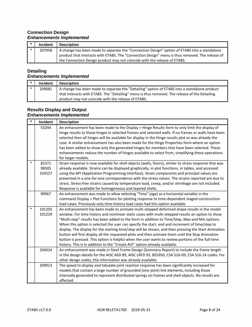
* 207958 A change has been made to separate the "Connection Design" option of ETABS into a standalone product that interacts with ETABS. The "Connection Design" menu is thus removed. The release of the Connection Design product may not coincide with the release of ETABS.
Detailing Enhancements Implemented
* Incident Description
* 209081 A change has been made to separate the "Detailing" option of ETABS into a standalone product that interacts with ETABS. The "Detailing" menu is thus removed. The release of the Detailing product may not coincide with the release of ETABS.
Results Display and Output Enhancements Implemented
* Incident Description
53294 An enhancement has been made to the Display > Hinge Results form to only limit the display of hinge results to those hinges in selected frames and selected walls. If no frames or walls have been selected then all hinges will be available for display in the Hinge results plot as was already the case. A similar enhancement has also been made for the Hinge Properties form where an option has been added to show only the generated hinges for members that have been selected. These enhancements reduce the number of hinges available to select from, simplifying these operations for larger models.
* 82371 98505
103527
Strain response is now available for shell objects (walls, floors), similar to stress response that was already available. Strains can be displayed graphically, in plot functions, in tables, and accessed using the API (Application Programming Interface). Strain components and principal values are presented in a one-for-one correspondence with the stress values. The strains reported are due to stress. Stress-free strains caused by temperature load, creep, and/or shrinkage are not included. Response is available for homogeneous and layered shells.
99967 An enhancement was made to allow selecting "Time" (age) as a horizontal variable in the command Display > Plot Functions for plotting response to time-dependent staged-construction load cases. Previously only time-history load cases had this option available.
* 101203 101229
An enhancement has been made to animate multi-stepped deformed shape results in the model window. For time history and nonlinear static cases with multi-stepped results an option to show "Multi-step" results has been added to the form in addition to Time/Step, Max and Min options. When this option is selected the user can specify the start, end and increment of time/step to display. The display for the starting time/step will be shown, and then pressing the Start Animation button will first display all the requested plots and then animate them until the Stop Animation button is pressed. This option is helpful when the user wants to review portions of the full-time history. This is in addition to the "Create AVI" option already available.
204024 An enhancement was made in Steel Frame Design (Summary Report) to include the frame length in the design details for the AISC ASD 89, AISC LRFD 93, BS5950, CSA S16-09, CSA S16-14 codes. For other design codes, this information was already available.
209913 The speed to display and tabulate joint reaction response has been significantly increased for models that contain a large number of grounded (one-joint) link elements, including those internally generated to represent distributed springs on frames and shell objects. No results are affected.

ETABS v17.0.0 ISO# RELETA1700 2018-05-31 Page 9 of 24
* Incident Description
215910 The speed has been increased for plotting base reactions for nonlinear modal time-history (FNA) load cases when using the command Display > Plot Functions. This improvement will be most notable for larger models having a lot of link elements at the base, including those used to model line (frame) and area (shell) spring supports.
216245 An enhancement was made to use multi-processing to significantly improve the speed of plot creation and animation for taller buildings when using the command Display > Combined Story Response Plots. This feature can be controlled using the command Options > Use Multi-processing for Design/Results.
Graphics Enhancements Implemented
* Incident Description
58884 An enhancement was made to show the location of the cursor in other model windows corresponding to the location of the mouse cursor in one window. This feature is enabled when the option Show Bounding Plane is enabled (Options menu). In 2-D windows the mouse cursor is tracked anywhere in the 2-D plane. In 3-D windows the mouse cursor is tracked only when the mouse cursor has snapped to a point or object.
* 94091 The Rendered View option is no longer available. It has been superseded by DirectX graphics in the regular model windows.
94239 An enhancement was made to the export of the graphical model display window as a DXF file (command File > Capture Picture > Current Windows as DXF/DWG) such that displayed text is now exported to a separate layer.
User Interface Enhancements Implemented
* Incident Description
201251 An enhancement was made to add a "Show" command to the Structural Object branch of the Model Explorer. This in in addition to the "Show Only" and "Hide" commands already available.
Documentation Enhancements Implemented
* Incident Description
85210 The composite beam design manuals for the AISC 360-05 and AISC 360-10 codes have been revised for clarity, and are consistent with the manual for the newly added AISC 360-16 code. Composite beam design results are not affected by this change except as may be documented under other incidents.
Drafting and Meshing Incidents Resolved
* Incident Description
58122 An incident was resolved where the Reshape tool was not working properly for certain operations on objects drawn at the Base level.
74660 96355
An incident was resolved where in rare cases areas on sloping planes assigned cookie-cut meshing may not get meshed correctly in that they may get partially disconnected from the rest of the structure. This was due to a tolerance issue and when it occurred it was obvious in the deformed shape plot.

ETABS v17.0.0 ISO# RELETA1700 2018-05-31 Page 10 of 24
* Incident Description
91613 An incident was resolved where copying and pasting of area objects from one model to another was not working as expected for certain models. This happened when the area edges were defined by numerous points instead of using curved edges. The copying and pasting process has been improved.
96726 An incident was resolved where replication of area objects with curved edges would replace the curved edges with straight edges for the replicated objects.
100309 102552
An incident was resolved where the Copy/Paste operation on a model or between models did not work properly when a rotation was applied to the Paste operation. Results agreed with the model as created. Note that copying from a 2-D view and pasting into a 3-D view measures the Delta-Z value from zero, not from the elevation of the plan view.
100335 An incident was resolved where during drafting operations for some property lists of drawing tools, if a drop-down list was opened and closed at once, the first value in the list was shown selected instead of the value that had been selected before opening the list. This has now been corrected.
100742 An incident was resolved where changing the maximum mesh size parameters under the Mesh > Cookie Cut option in the area object right-button click form would not immediately affect the mesh on-screen display in the model windows.
102351 An incident was resolved where, when drawing link objects in an elevation view using standard graphics mode, the end of the link object would not correspond with the position of the mouse cursor if the cursor was between grid lines. This issue was not present when drawing in other types of views or when using DirectX graphics mode.
103515 An incident was resolved where a triangular shell object would be deleted when using the editing command to split one of its selected edges.
103554 An incident was resolved where the default frame section was being assigned to beams added from the architectural layer rather than using the frame section chosen by the user. Results agreed with the model as created.
200230 An incident was resolved where the group assignment to a wall was not transferred to new wall objects created by division of the original wall object due to the presence of an opening. The division into smaller wall objects could occur using the Edit > Edit Shells > Divide Shells command, or automatically when the analysis is first run.
201338 An incident was resolved where frames were not meshed based on visible story grids when the number of stories crossed was large.
201344 An incident was resolved where using the command Edit > Edit Shells > Divide Walls for Openings would flip the normal (local axis 3) for the created walls. This did not invalidate results, but affected the consistency of the results as displayed due to the sign of the local 3 (normal) and local 1 (horizontal) axes. Results agreed with the local axes as generated.
Modeling Incidents Resolved
* Incident Description
94841 An incident was resolved where Fiber P-M-M hinges defined with the option “Default from Frame Section” used the same size rebar in the corners as along the sides for rectangular reinforced-concrete frame sections that had a specified rebar layout. This issue did not affect Section Designer frame sections, where the difference between rebar size in the corners and along the sides was correctly modeled by the Fiber P-M-M hinges. This issue also did not affect hinges where the fiber locations and sizes were explicitly specified by the user.
201972 An incident was resolved where a modal load case that was being used for modal damping in a direct-integration time-history load case was able to be deleted, resulting in no modal damping being applied. The deletion of modal cases used for modal damping is now prevented in the graphical user interface.

ETABS v17.0.0 ISO# RELETA1700 2018-05-31 Page 11 of 24
* Incident Description
202889 An incident was resolved where stiffness modifiers to the f12 direction of a wall element did not change the stiffness of a wall element when a nonlinear hinge was assigned to the element. This issue only affected wall elements with wall hinges assigned.
* 203153 An incident was resolved where the deformation-type hysteresis parameters for types Degrading and BRB Hardening were specified as a ratio of yield for rigid-plastic frame hinges, which have no yield deformation. The affected parameters are "Moderate Deformation Level" and "Maximum Deformation Level" for Degrading hysteresis; "Maximum Plastic Deformation at Full Hardening" and "Accumulated Plastic Deformation at Full Hardening" for BRB Hardening hysteresis. These parameters have been revised to specify these deformations (displacements or rotations) normalized by the hinge deformation scale factors instead of yield deformation. This only affects models with frame hinges that use Degrading or BRB Hardening hysteresis and non-default hysteresis parameters. For affected models, please review the specified hysteresis parameters in the new version of the software.
203739 An incident has been resolved to correct the following issues for the NZS 310 time-dependent properties: (1.) The user-defined basic drying shrinkage strain is used directly for shrinkage computation and Eqn 8.14 in the documentation is removed. (2.) The fc > 100 MPa condition for coefficient k5 for is removed and Eqn. 8.6 in the documentation is corrected.
204533 An incident was resolved where in certain cases the "Section Designer Section Property Data" form would cause an error condition caused by clicking "OK" without going into the Section Designer itself.
207474 An incident was resolved where the Frame Element Information form (from right-clicking the element in the display) displayed the Hinge location as the relative distance of the hinge multiplied by the full length of the element. However, the location of the hinge is the relative distance of the hinge multiplied by the clear length of the element plus the end length offset. The Element Information form has been corrected to accurately list the location of the hinge on the element.
208821 An incident was resolved for material properties of steel and rebar where the parametric option for the nonlinear stress-strain curve (Nonlinear Material Data form) was being generated using the Minimum Yield Stress and Minimum Tensile Stress values instead of using the Expected Yield Stress and Expected Tensile Stress values specified in the Material Property Design Data form. Now fiber hinges will use the expected stress values for nonlinear analysis. This change only affects materials that use parametric stress-strain curves. User-defined stress-strain curves are not affected.
209801 An incident was resolved where the automatically added embedded beam in wall objects that is intended to provide continuity to in-plane framing beams and columns may not have been fully effective in certain special cases. Specifically, this would occur if the beam or column was only present on one side and there was no wall above. The effect in most cases was insignificant. Equilibrium was always satisfied, but rotational continuity at the frame-to-wall joint was not fully realized.
Loading Incidents Resolved
* Incident Description
77189 An incident was resolved for the NBCC 2005 and NBCC 2010 auto seismic design codes where the values Fa and Fv were defaulted to 1.0 when model was imported from E2K text file when Site Class was not F. Similarly, for the NBCC 2015 auto seismic code, the values for the F02, F05, F1, F2, F5 and F10 parameters were defaulted to 1.0 when model was imported from E2K text file when Site Class was not F. Results agreed with the model as imported.
95073 An incident was resolved where negative values could not be entered for the X and Y coordinates of the wind exposure-width data in the auto wind load pattern definitions.

ETABS v17.0.0 ISO# RELETA1700 2018-05-31 Page 12 of 24
* Incident Description
201453 An incident was resolved for auto wind load cases based on Chinese 2010 code where "Phi Z Source" computed from Modal Analysis was incorrect for Wind Y.
* 202054 An incident was resolved where strain, temperature, or surface pressure loads assigned to a layered shell object were not being applied during nonlinear load cases (static, staged-construction, or direct-integration time-history) under certain circumstances. This issue occurred when there were multiple load patterns applied in the given load case, and for a given layered shell object there were strain, temperature, and/or surface pressure loads assigned in any of the applied load patterns except the first for that load case. This issue was not present if the load case contained only one load pattern and did not affect other types of area loads (e.g. self-weight, gravity, or uniform loading). This issue did not affect shell-object types other than the layered shell.
203420 An incident was resolved where deletion of a Load Pattern that was used in a Mass Source definition could cause the scale factors for other load patterns in the mass source, occurring in the list after the deleted one, to change. Results were consistent with the scale factors as shown.
Analysis Incidents Resolved
* Incident Description
56976 An incident was resolved where adding an auto notional load pattern, but not defining its parameters explicitly, would cause an error condition when the model was run. When this occurred, no results were available. Now default values are provided.
* 74529 101003
An incident was resolved where element loads on a shell element and specified to act in a fixed coordinate direction (such as gravity) would rotate with the element after being applied during an analysis with large-displacement geometric nonlinearity. This issue only affected nonlinear static and nonlinear direct-integration time history load cases with the "Geometric Nonlinear Parameters" set to "P-Delta plus Large Displacements". When this issue occurred, the computed response was in equilibrium with the rotated load and the issue was reflected in the reported forces and base reactions. Loads specified to act in an element-local coordinate direction are expected to rotate with the element under large-displacements, and that has not changed. Frame and link elements were not affected.
95474 An incident was resolved where changing the FEM Based Slab Design Overwrites after an analysis was already run would delete analysis results even though the overwrites do not affect analysis.
* 202146 An incident was resolved where the stiffness and self-weight of a frame object could vary with discretization if the frame was assigned both a non-prismatic section property and significant joint offsets. This issue only affected frame objects where the joint offsets and/or cardinal point changed the length of the frame object compared to the distance between the two end joints. This included the case where axial joint offsets were specified, and the case where transverse joint offsets inclined the local 1-axis with respect to the line connecting the two joints. Only frame objects that were discretized due to auto-meshing assignments or hinge overwrite lengths were affected. When this issue occurred, the differences in stiffness and self-weight were small and generally insignificant. Small changes in results may occur for models that use many non-prismatic frame section properties with significant joint offsets. Note that the affected joint offsets were those specified as part of the insertion point assignment. End offset assignments were not affected by this issue.
201375 202451
An incident was resolved where an error was generated when using the Modify Undeformed Geometry option was used if the model was imported earlier from a text file. Results were consistent with the geometry before attempting to use this command.

ETABS v17.0.0 ISO# RELETA1700 2018-05-31 Page 13 of 24
* Incident Description
203883 An incident was resolved where a message of "Error in creating Frame element hinges" would occur when end length offsets were specified for a frame object and it was broken into analysis elements within the offset. In this case the software would modify the offset to be shorter than the first element for I end and shorter than the last element for J end of the frame. Now this is no longer done and the original offset specification is kept. This may change some results if this rare condition occurred.
* 211888 An incident was resolved where frame loads, including self-weight, could have been incorrectly applied during nonlinear load cases where the Geometric Nonlinear Parameters were set to "P-Delta plus Large-Displacements". Load-case types that could be affected are nonlinear static, nonlinear staged construction, and nonlinear direct-integration time-history. This error only occurred when the number of threads used in the analysis procedure, which is reported in the .LOG file, was greater than 1. When this issue occurred, it created a discrepancy between the applied loading and computed results. In most cases this caused the analysis not to converge, and no results were available for the affected load cases. In some cases, the analysis would converge, and the results could then be incorrect. Only self-weight, gravity, concentrated-span and distributed-span loading applied to frames was affected. Temperature, strain, deformation, and target-force loads on frames were not affected. Loads on joints and other types of elements, including cables, were not affected. Nonlinear load cases with the Geometric Nonlinear Parameters set to "None" or "P-Delta" were not affected. This issue was present in ETABS 2016 versions 16.1.0 to 16.2.1. Affected load cases in the affected versions should be re-run in the new version to check the results.
212118 An incident was resolved where nonlinear static load cases with zero load applied may fail to converge if starting from a previous load case. This issue may also occur in staged construction load cases during the instantaneous load application portion of a stage where no major stage operations (loads applied, objects added, or objects removed) have been defined. In this release, the following changes are made: 1.) For nonlinear static load cases where no loads are applied, the relative iteration convergence tolerance will be determined relative to the total force present in the model. Normally the convergence tolerance is relative to the magnitude of the applied load, and that is still true when loads are applied, no matter how small. 2.) In nonlinear staged construction load cases, a stage that does not have any major stage operations defined will skip the instantaneous load application portion of that stage during analysis if the stage has duration for time-dependent effects. For a stage with no major operations and no duration, iteration will be performed based on a convergence tolerance relative to the total force present in the model. When iteration is performed with tolerances relative to the total force in the model, most models will converge immediately or with just a few iterations that improve equilibrium. Changes in results from previous versions are expected to be small and within the specified convergence tolerance for well-conditioned models.
212244 An incident was resolved for auto hinges using ASCE 41-13 where the program was adjusting the downward slope (between points C and D) of the backbone curve to avoid a vertical drop. This adjustment had a scaling error making it units dependent. Only the deformation at Point D was affected. The adjustment has been corrected.

ETABS v17.0.0 ISO# RELETA1700 2018-05-31 Page 14 of 24
* Incident Description
* 209096 An incident was resolved where the temperature loads applied in a linear load case could, in some cases, be incorrect for certain objects in the model if the linear load case used the stiffness from the end of a nonlinear staged-construction load case. This error would not occur if the linear load case was run in a subsequent session from the preceding nonlinear staged-construction load case. A subsequent session would be anytime the software was restarted, the model was re-opened, or anytime the analysis was run in a separate process (command Analysis > Analyze > Analysis Options > Solver Options). This error was uncommon, model-dependent, and machine-dependent. When it occurred, the results were generally erratic and obviously incorrect. Temperature loads are available for frame and shell objects. This error could affect ETABS versions 13.2.0 to 16.2.1, although no incidents have been reported.
* 212654 An incident was resolved where a model having more than one Parametric PMM hinge was unable to run modal time history load cases (linear or nonlinear FNA) that used the modes from a Ritz or eigen modal load case that in turn used the stiffness from the end of a nonlinear static, staged-construction, or direct-integration time-history load case. When this error occurred, no results were available for the modal time history load case. No other results were affected.
212894 The Material Nonlinear Parameters have been removed from the Nonlinear Parameters form that is available when defining nonlinear static and nonlinear direct-integration time-history load cases. These parameters were not able to be changed by the user and had no effect on the analysis. The listing of these parameters in the analysis log file (.LOG) has likewise been removed. There is no change to the behavior of the software or the analysis results.
* 214451 An incident was resolved where, when the "Change Sections" operation was used in a staged construction load case, the objects affected by the operation were being added into the structure with an age equal to the value last specified in the hidden "Age at Add, days" item of the operation definition. This issue only affected staged construction load cases where the nonlinear parameter "Time Dependent Material Properties" was enabled and when the "Change Sections" command was applied to objects which had time-dependent behavior specified for their material properties. The behavior of the "Change Sections" operation has been corrected so the elements with changed sections will retain the age of the previously existing object.
215596 An incident was resolved where a material property, hinge property, or nonlinear-plasticity link property using the Pivot-type hysteresis model and having a backbone curve with compression-only or tension-only behavior (i.e., zero force and stiffness in one direction) would produce undefined analysis results after yielding occurred. These analysis results would be reported as "NaN" (not a number) instead of as numerical values. Graphical displays of such analysis results would be blank. This behavior could affect all response quantities reported for the model, not just for those objects using the nonlinear material, hinge, or link property itself. Only nonlinear load cases and linear load cases using the stiffness at the end of a nonlinear load case could be affected. Nonlinear material properties only affect fiber hinges and layered shells. This error was not common since the Pivot model is not really applicable to tension-only or compression-only behavior.
216323 An incident was resolved where a material property defined with nonlinear hysteresis type "Isotropic" was being treated as a "Pivot" hysteresis model with the following properties: Alpha1 = 100, Alpha2 = 100, Beta1 = 1, Beta2 = 1, and Eta = 0. This would only affect nonlinear static and direct-integration time-history load cases for models where such a material was used in fiber hinges (frame or wall) and/or in layered shells. The energy dissipation would be less than expected for an "Isotropic" hysteresis model, and would be similar to that for the "Takeda" hysteresis model.
216608 An incident was resolved where the transverse shear stiffness was too flexible by a factor of two for layered shell elements with nonlinear properties (both Directional and Coupled types). Layers where the components S11, S22 and S12 were all specified as Linear and/or Inactive were not affected. For a shell element with multiple layers, only those layers with one or more components specified as Nonlinear contributed to the excess flexibility. For most models, where flexural flexibility dominates, the effect of this error was negligible.

ETABS v17.0.0 ISO# RELETA1700 2018-05-31 Page 15 of 24
Frame Design Incidents Resolved
* Incident Description
* 93936 204335
An incident was resolved for steel frame design of pipe sections where the section classification may have been incorrect in some cases. If the frame section came from a database file this was not an issue. If the section was added by manually providing dimensions, the wall thickness used for classification could have been incorrect. For this latter case, the classification should be verified by re-running the design in the new version. The section properties used for design were not affected by this error, only the classification.
101382 An incident has been resolved for steel frame design in all codes where the demand/capacity ratio limit from the Design Overwrites for individual members was not being used for member optimization. Instead the demand/capacity ratio limit from the Design Preferences was always being used. Now the design process for each member uses the demand/capacity ratio limit from the Overwrites, if specified, or else it will use the demand/capacity ratio limit from the Preferences if not overwritten. To avoid confusion during the color display of member demand/capacity ratios and the error messages provided in the design details window and the database tables, the use of the demand/capacity ratio limit is restricted to the determination of the acceptability of a frame section during optimization and design check.
* 101592 An incident has been resolved for steel frame design using codes "AISC 360-05", AISC 360-10", and "KBC 2009" in which the reported load combinations corresponding to the governing beam/column capacity ratios (BCCR) in tables and in the design details were incorrect. The reported design combination was always the last load combination in the list of considered combinations instead of the governing one. This was a reporting problem only. The BCCR values themselves were correct.
101901 An incident was resolved for concrete frame design using the Chinese 2010 in which the calculation of λ (lambda) for columns was not correct for two reasons: (1.) In the calculation of λ, the full depth of column was used instead of the effective depth h0. λ should be equal to M/(V*h0). (2.) The program used the values of M and V after modification with magnification factors SMF and MMFs instead of using the values of M and V before modification with magnification factors SMF and MMFs. The calculated λ values should not change with the overwrites of magnification factors for columns. This issue was only present for columns. The lambda values for beams are calculated based on the actual presence of a point load, if any. If there is no point load on beam, then λ is taken as 1.5. The calculation of λ for beams was not changed.
101903 An incident was resolved for concrete frame design per the "Chinese 2010" code where the concrete joint-shear design Gamma_RE value of 0.75 was used instead of 0.85. Now the design uses the correct value of 0.85 and it reports it in the design details accordingly.
* 102556 An incident was resolved for composite column design per the Chinese code where the design axial forces were incorrect for seismic loading. The error was obvious, and the design should be rerun with the new version if seismic design was considered.
201458 An incident was resolved for concrete column design where column design details were lost after the design was saved and model was reopened again after closing and restarting ETABS.

ETABS v17.0.0 ISO# RELETA1700 2018-05-31 Page 16 of 24
* Incident Description
201669 204405
An incident was resolved for axial compression capacity, Cr, of steel frame design using the CSA S16-09 code where the value of Cr in certain conditions (when “n” was calculated as 2.24 or overwritten as greater than 1.34) was calculated conservatively. The power "n" which could be 1.0, 1.34, 2.24, or any overwritten value was used in calculating the axial compression capacity for flexural buckling per CSA 13.3.1 based on Euler buckling stress for major and minor axes bending (Fex and Fey). That was correct. The power "n" with a value of 1.34 was used in calculating axial compression capacity for the flexural, torsional, or flexural-torsional buckling per CSA 13.3.2 based on Euler buckling stress Fe (CSA 13.3.2). In the latter case for certain conditions (for any doubly symmetric shape) Fe was taken as the minimum of its values for two flexural modes (Fex and Fey) and one flexural-torsional buckling mode (Fez) (CSA 13.3.2(a)). The Cr calculated based on section CSA 13.3.2(a) with an n=1.34 was always smaller than that calculated based on CSA 13.3.1 when the calculated “n” was equal to 2.24 or overwritten as greater than 1.34. The current version of the program does not take Fe as the minimum of Fex, Fey, and Fez for the flexural-torsional buckling mode anymore. Rather it considers this mode as strictly flexural-torsional mode and takes Fe=Fez. This implementation makes sure that flexural mode uses the calculated “n” or its overwritten value whereas the flexural-torsional buckling mode uses n=1.34. The implementation for CSA S16-14 had similar problem regarding Fe as the minimum of Fex, Fey, and Fez which is fixed. The CSA S16-14 code however always used the value of “n” as either the calculated value or the overwritten value irrespective of the mode. Now both the codes use the same value of “n” and similar value of Fe for flexural-torsional buckling mode. Both codes have been enhanced to now report n, KL/r, Lambda, Cr, and other values for all modes.
202315 An incident was resolved for concrete frame design using the Indian IS 456:2000 code where the minimum eccentricity moment in the minor direction could be incorrect when the unbraced lengths of the column were different in the major and the minor directions. The unbraced length in the major direction was being used for computing the minimum eccentricity moment in both major and minor directions.
* 203061 An incident has been resolved for concrete frame design using code “Eurocode 2-2004” in which the second-order effect calculation (EC3 5.8.7.2 and EC3 5.8.8) for the column-design moment (MEd) was incorrect when there was an in-span load in the column. The design could have been unconservative when there is an in-span lateral load on the column. The calculation of load due to geometric imperfection per EC3 section 5.2 was also corrected. Note that the results for Verification example "EN 2-2004 Example 002" has changed slightly, and the Verification Manual has been updated accordingly. The magnitude of the change is insignificant for verification purposes.
206924 An incident has been resolved for concrete frame design using the "Eurocode 2-2004" code where the value of Ec was being recomputed from material strength instead of using the value already specified as part of the material property.
212857 An incident was resolved for steel frame design per the “Eurocode 3-2005” code where the detailed design report did not correctly report the status of a section as to whether it was rolled or not; results were not affected. In addition, the documentation was missing a row in Table 5.2 regarding the buckling curves for a welded pipe section.

ETABS v17.0.0 ISO# RELETA1700 2018-05-31 Page 17 of 24
Composite Beam Design Incidents Resolved
* Incident Description
87639 200959
Several incidents related to the vibration check per Design Guide 11, which is an optional part of composite beam design per AISC 360-05, AISC 360-10, CSA S16-14 and EuroCode 4-2004 codes were resolved. 1.) Beam weights were always amplified by 50% for vibration check. This weight amplification was only valid when the beams in adjacent bays were connected to the beam being designed through a girder web and had spans no less than the 70% of the span of the beam being designed. The 50% weight amplification is now applied only when the adjacent beams meet the preceding criteria. 2.) The floor length and width were set at 3 times the beam span and three times the girder span, respectively, regardless of the actual extents of the framing. The floor length and width are now computed based on the extents of the framing at the story and in the tower where the beam being designed occurs. The floor length and width are measured parallel and perpendicular to the beam being designed, respectively, at its location. Additionally, the values of the floor length and width are reported in the composite beam design output and can be modified by the user in the composite beam design overwrites form. 3.) The coefficient Cj used to compute the beam effective width Bj was always taken as 2.0. It should be taken as 1.0 when the beam is adjacent to a free edge. ETABS now considers the beam as adjacent to a free edge when it is at the limit of the building, or next to an opening. The user can explicitly tell ETABS whether the beam is parallel to a free edge in the beam overwrites. 4.) The value of the supporting-girder transformed moment of inertia per unit width was twice its allowed value when the girder was at the limit of the building, or next to an opening. The value of the girder transformed moment of inertia per unit width is now based on two times the beam span, instead of one, for these girders. None of the above incidents affected the strength or deflection acceptability of any of the composite beams that were designed.
95030 An incident was resolved where the size of beam cope at the end of a composite beam that framed into a concrete-encased steel girder was based on the flange width the encased steel girder instead of its flange thickness. This could affect the shear strength of the composite beam, but the error was always conservative.
101693 An incident was resolved which affected the interactive design of composite beams that were part of a composite design group that also included beams whose design procedure was different. If, while interactively changing the design of one of the composite beams, the user clicked the OK button, ETABS would display a number of error messages while attempting to apply the selected composite design to the various other beams in the group whose design procedure was different. ETABS now skips these beams when applying a design selected interactively to a composite design group of beams. When this error occurred, the design of these beams was either unchanged or was obviously wrong. The problem did not occur when groups containing only composite beams were used as composite beam design groups. This incident was actually resolved in the previous release of ETABS 16.2.0, but was inadvertently omitted from the Release Notes at that time.
103207 An incident was resolved where the live load reduction factor (LLRF) was shown as negative in the composite beam design output when the value of the LLRF had been specified by the user in the beam overwrites. This was just a reporting issue and no design results were affected. In addition, the user can now specify a value of 1.0 for the LLRF - meaning no live load reduction. Previously, when the user specified a value of 1.0 in the composite beam overwrites form, the input was accepted, but not recorded.

ETABS v17.0.0 ISO# RELETA1700 2018-05-31 Page 18 of 24
* Incident Description
* 201395 An incident was resolved for composite beam design which affected the design of cantilevers and continuous beams with a user-specified shear stud distribution during interactive design mode, and also in automatic design mode if the beam had a user-specified steel section, as opposed to using an auto-select list. The negative bending stress check was not performed and not reported. This issue occurred with composite beams designed in ETABS 16.2.0 and 16.2.1. Composite beams designed in earlier versions of ETABS, composite beams without a user-specified shear stud distribution, and composite beams using an auto-select list section and designed in automatic mode were not affected.
210055 An incident was resolved which affected composite beam design. When the user specified shear stud distributions in the design overwrites of composite beams, ETABS did not check these beams for vibrations, even if a vibration criterion had been specified. Composite beams whose shear stud distributions was determined automatically by ETABS were not affected. When this error occurred, the strength and deflection of the beams were not affected. This incident affected composite beams designed in ETABS versions 16.2.0 and 16.2.1 only.
215416 An incident which affected composite beam design output per all codes has been fixed. When two of the beams framing into a composite girder were located so closely along the girder axis that no shear studs were required in the girder stud segment located between the two beams, ETABS incorrectly called out a far greater number of shear studs than required or than could even fit on the beam due to a missing comma between two subsequent numbers of shear studs. When this occurred, the error was obvious, and the strength of the beam was greater than required. Girders for which a uniform shear stud distribution was selected were not affected. The missing comma is now properly inserted in the shear-stud distribution. This was a graphics display issue and the tables were correct.
Shear Wall Design Incidents Resolved
* Incident Description
93759 An incident has been resolved in the Overwrites for shear-wall design data in which clicking Set to Default Values on “All Items” in the Wall Pier Design Overwrites form was setting the items with their corresponding default values in their original units instead of using the current Display units. When using one set of units to create the model and another set of units to display the values, this could have the potential of corrupting the corresponding Overwrite data that are unit-dependent. Some such Overwrite values include the edge-bar spacing and clear cover. Similarly, certain of the Overwrite data for steel frame design, concrete frame design, and spandrel design were affected. This issue was limited to values that are unit-dependent, which are very few, and only when the "Set to Default" button was used. Design results agreed with the Design Overwrite data as set and shown in the form.
94570 An incident has been resolved for concrete shear-wall design using ACI codes in which the upper limit of fys was not being imposed for shear design. The limit now being enforced is fys ≤ 60 ksi (ACI 318-08 9.4, 11.4.2, 21.1.5.5; ACI 318-11 9.4, 11.4.2, 21.1.5.4; ACI 318-14 20.2.2.4a). This limit will affect the shear design of wall piers and spandrels. The affected codes are ACI 318-08, ACI 318-11, and ACI 318-14. The documentation has been updated accordingly.
102374 An incident was resolved for concrete shear wall design per the “Eurocode 2-2004” code where the drop-down box for the design overwrite "Seismic Ductility for Spandrels" on the form "Wall Spandrel Design Overwrites for Eurocode 2-2004" was not providing the correct options. Now the options are "DC High", "DC Medium", "DC Low", and "Secondary". The effect on results was generally small.

ETABS v17.0.0 ISO# RELETA1700 2018-05-31 Page 19 of 24
* Incident Description
201025 208677
An incident was resolved for ACI 318-14, ACI 318-11 and ACI 318-08 design codes where the wall design report was showing a message "Error occurred during showing of information" when multi-leg piers were present in the model. This issue only affected v16.2.0 and v16.2.1, although it was partially resolved in 16.2.1.
201903 An incident was resolved for shear wall design using the Indian IS 456:2000 code where setting the design preference "Consider Minimum Eccentricity Minor?" to "No" was also affecting the minimum eccentricity in the major direction. This error was evident from the design report which showed minimum eccentricity moment in the major and the minor axes as both being zero.
206740 An incident was resolved where shear wall design based on IS 456:2000 code sometimes gave the error "Unable to calculate interaction diagram for section". When this occurred, no results were available.
216139 An incident was resolved for concrete shear wall design of spandrels per the AS3600-2009 code where the minimum shear rebar Asv,min computed using equation 8.2.8 was incorrect when the model database units were not in N-mm. This was only an issue for models started using US Customary units, or for models originally created in ETABS v9 with database units different from N-mm.
Results Display and Output Incidents Resolved
* Incident Description
73140 An incident was resolved where the pan was not working correctly on the print graphics preview form when the area stress contours were being displayed.
* 87320 214774
An incident was resolved where the hinge status reported in tables was inconsistent from that reported in the on-screen display and on hinge plots. The hinge status reported in tables was incorrect and off by one state in some instances. The plastic deformations reported and the branch of the stress-strain/force-deformation reported were both correct.
101033 An incident was resolved where the story response plots for story shear and overturning moment were not correct for stories supported by area (shell) springs, such as along basement walls. The total shear or moment, including the spring forces, was being reported, rather than just the shear or moment carried by the structure. This tended to be over-conservative. This was only a reporting error. No other results were affected. The error affected versions 16.0.0 to 16.2.1.
103819 203752
An incident was resolved where the error message “Unable to calculate target displacement. Iterative solution did not converge.” would appear when trying to view certain Static Pushover Plots. For these cases this was caused by a large side-sway under gravity loads that were being used as initial condition for the Static Pushover case. This is now detected and a correction applied.
202078 An incident was resolved where the "Absolute Max" option for displaying the shell forces was not working properly in some cases. When it failed it would plot the "Min" value. The "Max" and "Min" plots were correct. This was an on-screen display error only.
202296 An incident was resolved where, for certain models, right-clicking on a frame member to the details of a force or moment diagram for a time history load case could result in an abnormal termination. Results were not affected.

ETABS v17.0.0 ISO# RELETA1700 2018-05-31 Page 20 of 24
* Incident Description
203009 A minor change has been made for the reporting of steel frame design results using the command Design > Steel Frame Design > Display Design Info where the name of the design output item "P-M Colors/Beam Shear Force" has been changed to "P-M Colors/Beam End Shear Force." The reason for this change is to emphasize that the shear force is reported only at the ends of the member where it is supported by a wall, column, brace, diaphragm, etc., as would typically be needed for connection design. If a horizontal member is split into multiple elements, the joints between the segments are not supported by any other member and the shear force at the ends of these internal segments are intentionally left blank. The affected codes are "AISC 360-10", "AISC 360-05", "Eurocode 3-2005", "IS 800:2007", "Italian NTC 2008", "KBC 2009". No results are affected and the actual reporting is unchanged.
201249 An incident was resolved where the contour range shown on the Shell Force Display form would show inconsistent behavior when the component displayed was changed. The new behavior is that it will maintain values if the units of the display remain the same when the component is changed or will revert back to default values when the units change.
204462 An incident has been resolved for concrete frame design using code “IS 456-2000” in which there was an issue regarding the reporting of the beams connected to the column in the design details. The headers and the values were not displayed correctly when there was no beam connected to the column. This was a reporting issue only. All calculations were correct.
209871 An incident was resolved for steel frame design using the AISC ASD 89 code where the last column in the Table "Moments and Capacities" should have been titled F'e instead of Fb in the design report. This was just a labeling issue and no design results were affected.
215045 An incident was resolved where the story response plots for multi-stepped load cases and combinations using the Max Absolute Value option was producing confusing plots because of the lack of correspondence for plotted values between the different stories. This option has been removed. Results are unaffected.
Graphics Incidents Resolved
* Incident Description
77200 An incident was resolved where extra lines would sometimes appear in the view when area (shell) objects were displayed as extruded. This issue was uncommon and only affected a few models, and then only when certain operations were performed before the extrusion. No results were affected.
79285 An incident was resolved where the plan view of wall objects was displayed incorrectly when the walls consisted of different thicknesses. This was just a display issue and results were unaffected.
80404 An incident was resolved where setting story display limits would sometimes not work correctly for elevation views. This was a display issue only and affected multi-tower models more.
82891 An incident was resolved where graphically selecting objects in plan views would select objects both above and below the displayed story level in multi-tower models, whereas only the objects below the story level were selected in single-tower models. The behavior for multi-tower models has been corrected so that objects above the story level are not selected when working in plan views for any model.
84706 An incident was resolved where vertical display limits for multi-tower structures would sometimes not be correctly applied and an additional story would be displayed below the bottom elevation set by the user. This affected the command View > Set Building View Limits, and could be particularly obvious when rotating a 3-D view.
86396 An incident was resolved where the window zoom and right click would not work correctly in plan view if a rotated and translated grid system was selected to obtain screen coordinates.
ETABS v17.0.0 ISO# RELETA1700 2018-05-31 Page 21 of 24
* Incident Description
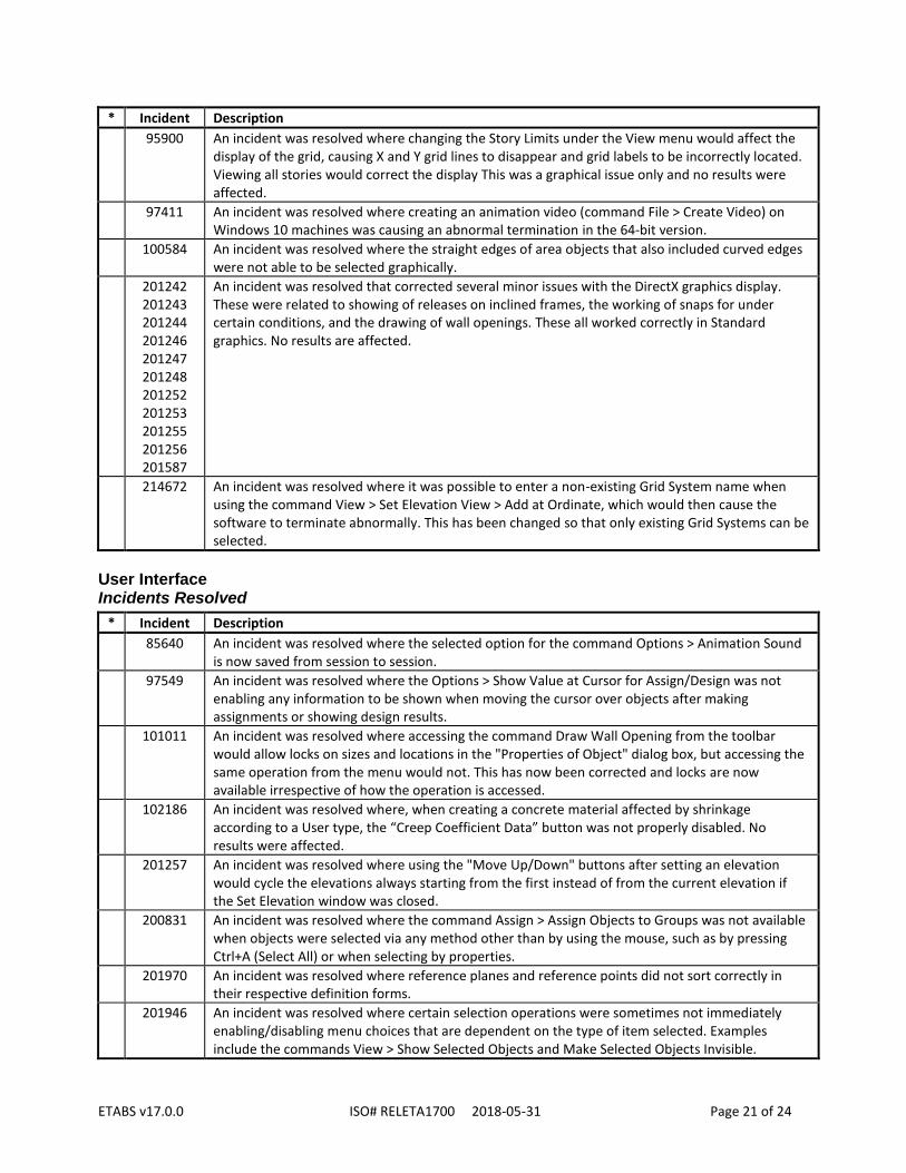
95900 An incident was resolved where changing the Story Limits under the View menu would affect the display of the grid, causing X and Y grid lines to disappear and grid labels to be incorrectly located. Viewing all stories would correct the display This was a graphical issue only and no results were affected.
97411 An incident was resolved where creating an animation video (command File > Create Video) on Windows 10 machines was causing an abnormal termination in the 64-bit version.
100584 An incident was resolved where the straight edges of area objects that also included curved edges were not able to be selected graphically.
201242 201243 201244 201246 201247 201248 201252 201253 201255 201256 201587
An incident was resolved that corrected several minor issues with the DirectX graphics display. These were related to showing of releases on inclined frames, the working of snaps for under certain conditions, and the drawing of wall openings. These all worked correctly in Standard graphics. No results are affected.
214672 An incident was resolved where it was possible to enter a non-existing Grid System name when using the command View > Set Elevation View > Add at Ordinate, which would then cause the software to terminate abnormally. This has been changed so that only existing Grid Systems can be selected.
User Interface Incidents Resolved
* Incident Description
85640 An incident was resolved where the selected option for the command Options > Animation Sound is now saved from session to session.
97549 An incident was resolved where the Options > Show Value at Cursor for Assign/Design was not enabling any information to be shown when moving the cursor over objects after making assignments or showing design results.
101011 An incident was resolved where accessing the command Draw Wall Opening from the toolbar would allow locks on sizes and locations in the "Properties of Object" dialog box, but accessing the same operation from the menu would not. This has now been corrected and locks are now available irrespective of how the operation is accessed.
102186 An incident was resolved where, when creating a concrete material affected by shrinkage according to a User type, the “Creep Coefficient Data” button was not properly disabled. No results were affected.
201257 An incident was resolved where using the "Move Up/Down" buttons after setting an elevation would cycle the elevations always starting from the first instead of from the current elevation if the Set Elevation window was closed.
200831 An incident was resolved where the command Assign > Assign Objects to Groups was not available when objects were selected via any method other than by using the mouse, such as by pressing Ctrl+A (Select All) or when selecting by properties.
201970 An incident was resolved where reference planes and reference points did not sort correctly in their respective definition forms.
201946 An incident was resolved where certain selection operations were sometimes not immediately enabling/disabling menu choices that are dependent on the type of item selected. Examples include the commands View > Show Selected Objects and Make Selected Objects Invisible.

ETABS v17.0.0 ISO# RELETA1700 2018-05-31 Page 22 of 24
* Incident Description
202812 An incident was resolved where an error message was generated after minimizing and then redisplaying the ETABS window while the analysis is running if the deformed shape or other results were being displayed prior to starting the analysis. For this to occur some of the load cases had to be run previously, then additional load cases run prior to minimizing the window. When this occurred, results may not be available for the load cases not previously run. The error message was typically "Error in recovering active member:p::a CsiGo Error details: kFatal = 8".
204420 An incident was resolved where in the Time Dependent Properties for Concrete form with Time Dependent Type "AS 3600-2009", the drop-down menu for the item "Environment" had duplicate values.
206674 An incident was resolved where, on the Section Cut Data form for defining a section cut, the data grid for specifying "Quadrilateral Cutting Planes" appeared to be active for entering data (even though it was actually disabled) when the option for "Section Cut Defined By" was changed from "Quadrilateral Cutting Planes" to "Group".
Database Tables Incidents Resolved
* Incident Description
* 102124 An incident was resolved for concrete shear wall design in which the “Shear Wall Pier Summary” tables for the various codes did not show an error message as expected when the shear wall failed if pier section type was “Simplified T and C". This was a reporting error in the database tables only. The Design Details and the on-screen display showed the error message correctly. Other pier section types were not affected.
102433 An incident was resolved which affected the display of composite beam design results "Detailed Data" tables. When the user set the beam type of a composite beam to any option other than "Composite as required" in the design overwrites of the beam, then the composite beam design results of that beam were missing from the generated table. When this occurred, the error was obvious, and the beam design results were available in other reports.
207356 An incident was resolved where the database tables for response spectrum functions, auto wind loads, and auto seismic loads for certain newer codes were not available in the reports. This was a results-display issue only and did not affect results.
208144 An incident was resolved where exporting a table set with multiple groups selected for filtering the output did not generate the expected output. Only the first selected group was considered when filtering the data. This was an output issue only and did not affect results.
211692 An incident was resolved for American and Korean design codes where Sds, Roh and Omega0 factors were missing from the concrete and wall design preferences tables. No results were affected.
Data Files (.EDB, .E2K, .$ET) Incidents Resolved
* Incident Description
84170 An incident was resolved where certain specific model files were unable to be opened due to an error condition encountered when trying to display architectural text objects. Such models could be imported from text files. This error was not common and did not affect results.
89700 An incident was resolved for importing models from text files where, if a database section was a duplicate of another section but with different material properties, the section would import incorrectly as a general section with default properties. Results were consistent with the model as imported.

ETABS v17.0.0 ISO# RELETA1700 2018-05-31 Page 23 of 24
* Incident Description
94763 An incident was resolved where it was possible to import the frame section material different from the base material of the corresponding section designer section when importing from a text file. This has been corrected by only importing the frame section material and initializing the section designer base material from it. Older files have been corrected.
201337 203893
An incident was resolved where the shell edge releases were not getting imported correctly through the model text file.
203825 An incident was resolved where the “Number of Terms” for Dirichlet Series in the material Time Dependent Properties for Concrete form was not being exported to the text file is is was set to the default value of 10. When such a text file was later imported, the value would then be set to zero, which was not legal. This has been corrected.
External Import/Export Incidents Resolved
* Incident Description
98471 An incident was resolved where the option "Similar Stories" was not working for some models when drawing objects using the command File > Import > .DXF/.DWG File of Architectural Plan command.
100701 An incident was resolved in which ETABS could terminate if the export of database tables was cancelled when asking for the Microsoft Access filename. No results were affected.
102599 An incident was resolved which affected the export of model elevations to AutoCAD DXF files. When the first defined grid system in the ETABS model was rotated from the X and Y axes, elevations located on the grid lines of this grid system were not exported and DXF files without any content were created. Elevations located on the grid lines of rotated grid systems can now be exported as DXF files.
Application Programming Interface (API) Incidents Resolved
* Incident Description
200219 An incident was resolved where the API (Application Programming Interface) function cPropLink.SetMultiLinearPoints would impose an input parameter restriction on force that was not consistent with the user interface.
200350 An incident was resolved for the Application Programming Interface (API) where the GroupDef.GetAssignments method was also retrieving objects deleted since the last time the model was saved.
201986 203123 204359 214886
An incident was resolved for the API (Application Programming Interface) where the SapModel.Story.SetStories function could cause a compilation error in VBA client applications. The function has been superseded by the SetStories_2 function. The GetStories_2 function has also been added.
203092 An incident was resolved for the API (Application Programming Interface) where the function cAnalysisResults.AreaJointForceShell was unable to return results for a single element. When only one object was selected for output, the function worked correctly when the object was auto-meshed and contained more than one internal element, but not for a single object that was not meshed.
203798 An incident was resolved wherein ETABS API (Application Programming Interface) function PropMaterial.SetMassSource_1 set both "Element Self Mass" and "Additional Mass" to true if either of the IncludeElements or IncludeMass arguments to the API function were true. The arguments IncludeElements and IncludeMass now independently set the state of "Element Self Mass" and "Additional Mass", respectively.

ETABS v17.0.0 ISO# RELETA1700 2018-05-31 Page 24 of 24
* Incident Description
214398 An incident was resolved for the API (Application Programming Interface) where the function cFrameObj.SetReleases was ignoring the parameters StartValue and EndValue when specifying partial fixity, such that the stiffness was zero and acted as if fully released. Unreleased degrees of freedom were not affected.
Documentation Incidents Resolved
* Incident Description
90304 A documentation error was corrected for CSA A23.3-04 and CSA A23.3-14 shear wall design manuals by deleting the "Note: In the overwrites, Vc can be specified to be ignored (set to zero) for spandrel shear calculations." in section 3.2 as it was not applicable for these codes.
93716 The Multi-Step Animation help topic has been updated to reflect the ability to create videos for nonlinear static and staged-construction load cases.
87698 96171
The concrete frame design manuals for the ACI 318-11 and ACI 318-14 codes have been updated to clarify the use of phi factors for shear design based on factored load with seismic load, and on the capacity shear load. In the first case the factor is 0.6 (ACI 318-11 9.3.4(a); ACI 318-14 21.2.4.1) whereas in the second case the factor is 0.75 (ACI 318-11 9.3.4(a) and 9.3.2.3; ACI 318-14 21.2.4.1 and 21.2.1). No results have changed.
101906 A documentation error was corrected in the Auto Lateral Loads manual for the 1997 UBC Seismic Loads. The "Program Calculated" time period in section 2.4.1 was incorrect, and has been updated as follows: – If Tmode > 1.30TA, then T = 1.30TA. – If Tmode > 1.40TA, then T = 1.40TA. This was a documentation error only. Results were consistent with the corrected values above, and have not changed.
204461 An incident has been resolved for the documentation of the concrete frame design code “IS 456-2000” in which minor updates have been made for the following issues: (a) the effect of axial force on flexural design, (b) the limit expression for the depth of the compression block, (c) the limits of As and As’, (d) capacity shear calculations, (e) the inclusion of gamma_s instead of the factor 1.15 or 1/gamma_s instead of 0.87 in shear and torsion design equations, and (f) several grammatical corrections. This was a documentation issue only. All calculations were correct and no changes have been made to the software for these issues, hence results are not affected.
204460 An incident has been resolved in the documentation for the concrete frame deign code “AS 3600-2009” in which the concrete cover for torsion check, c, was not represented correctly in Figure 3.9 of the manual. The figure has been updated to correctly show the torsion cover measured from the center of the rebar instead of using the clear cover. This was a documentation issue only. All calculations were correct and have not changed.