erj 190 – 100/200 - dallorto.com 3.7 - 25.08.2017.pdf · erj 190 – 100/200 ... nosewheel &...
TRANSCRIPT

2017 – 3.7
FARRETONES TIP GUIDE
25/8/2017
ERJ 190 – 100/200
OPERATIONAL TIPS GUIDE
www.aviationforall.com/docs/erj
@ejetguide

25/08/2017 - DOES NOT REPLACE THE ORIGINAL PUBLICATIONS. DO NOT USE FOR FLIGHT!!! FARRETONES 3.7
Review
Nº Reviser Date Signature
ORIGINAL 1.0 - 03/07/2014 -
REV-1 2.0 L. F. Farret 05/07/2014
REV-2 3.0 L. F. Farret 07/07/2014
REV-3 3.1 L. F. Farret 11/08/2015
REV-4 3.2 L. F. Farret 22/08/2016
REV-5 3.3 L. F. Farret 26/09/2016
REV-6 3.4 L. F. Farret 25/01/2017
REV-7 3.5 L. F. Farret 03/04/2017
REV-8 3.6 L. F. Farret 14/08/2017
REV-9 3.7 L. F. Farret 25/08/2017
25/08/2017 - DOES NOT REPLACE THE ORIGINAL PUBLICATIONS. DO NOT USE FOR FLIGHT!!! FARRETONES 3.7
Table of contents
Introduction ...................................................................................................................................................... 6 Abbreviations ................................................................................................................................................... 7 Safety and Power-Up Checklist.................................................................................................................... 11
Safety ........................................................................................................................................................... 11
Power-Up ..................................................................................................................................................... 12
Receiving Checklist ....................................................................................................................................... 13 Exterior Inspection ........................................................................................................................................ 14 Cockpit Preparation ....................................................................................................................................... 15
F.O. ............................................................................................................................................................... 15
CAPT ............................................................................................................................................................ 16
Before Start To the Line ................................................................................................................................ 17 Takeoff Briefing .............................................................................................................................................. 18 Below the Line ................................................................................................................................................ 19 Engine Start .................................................................................................................................................... 20 Exterior lights ................................................................................................................................................. 21 After Start ........................................................................................................................................................ 22 Before Takeoff ................................................................................................................................................ 23 Below the Line ................................................................................................................................................ 24 Takeoff............................................................................................................................................................. 25
Setting Takeoff Thrust ............................................................................................................................... 25
Initial Steering ............................................................................................................................................. 25
Aft Center-of-Gravity Effects .................................................................................................................... 25
Crosswind Takeoff ..................................................................................................................................... 25
Rotation and Liftoff .................................................................................................................................... 25
Initial Climb ................................................................................................................................................. 25
Clean-Up and Acceleration ....................................................................................................................... 25
Close-in turn after takeoff ......................................................................................................................... 26
ECS off Takeoff........................................................................................................................................... 27
Noise Abatement Takeoff .......................................................................................................................... 28
Takeoff Limitations .................................................................................................................................... 28
After Takeoff ................................................................................................................................................... 29 Climb ............................................................................................................................................................... 30 Transition Altitude ......................................................................................................................................... 30 FL 100 .............................................................................................................................................................. 31 Cruise .............................................................................................................................................................. 32 Descent Preparation ...................................................................................................................................... 33 Descent ........................................................................................................................................................... 34
Idle Descent example in the MCDU:......................................................................................................... 34
Descida por Instrumentos em Locais Desprovidos de Órgãos de Controle de Tráfego Aéreo ....... 35
Razão de Descida ....................................................................................................................................... 35
Holding Speeds Tables – DOC8168 ......................................................................................................... 35
Approach Speed Table .............................................................................................................................. 36
Equipment and Minimums needed for Approach Procedures ............................................................. 36
Corrections in case of equipment failure – ILS CAT I & II ..................................................................... 36
FL 100 .............................................................................................................................................................. 37 Transition Level ............................................................................................................................................. 38

25/08/2017 - DOES NOT REPLACE THE ORIGINAL PUBLICATIONS. DO NOT USE FOR FLIGHT!!! FARRETONES 3.7
Approach Procedures ................................................................................................................................... 39 Stabilized Approach Criteria ..................................................................................................................... 39
Minimums / Go-Around Altitude Selection ............................................................................................. 40
Approach Switch Selection and Display Guide ...................................................................................... 41
Using GD (Green Dot) ................................................................................................................................ 41
Precision Approaches (ILS, ILS/DME) ......................................................................................................... 42 Determining Decision Altitude/Height ..................................................................................................... 42
ILS Approach Sequence CAT I Profile ..................................................................................................... 42
BARO VNAV ................................................................................................................................................ 43
Non-Precision Approach ........................................................................................................................... 44
Display Controller Panel and Bearing Pointers Selection .................................................................... 44
Setting Minimums ...................................................................................................................................... 44
Continuous Descent Flight Path (LOC, BARO VNAV, RNAV, VOR and NDB approaches): ............. 45
RNAV Approaches ..................................................................................................................................... 46
Required Navigational Performance (RNP)............................................................................................. 46
Discontinuing the Approach ..................................................................................................................... 46
VNAV Approaches ..................................................................................................................................... 46
RNP-AR APCH ............................................................................................................................................ 46
Circling Approach ...................................................................................................................................... 47
Side-Step Maneuver ................................................................................................................................... 47
Visual Approach ......................................................................................................................................... 48
Prior to the “Landing” Callout .................................................................................................................. 48
Landing Callout .......................................................................................................................................... 48
HUD A3 (CAT II) ILS Approach (Applicable only for certified crew) .................................................... 49
HUD A3 (CAT II) Approach Procedure ................................................................................................. 49
HUD A3 (CAT II) ILS Approach Sequence Profile ............................................................................... 49
Standard Braking, Reverse and Flap Configurations ............................................................................ 50
Reverse Thrust Reduction ........................................................................................................................ 50
Braking. ....................................................................................................................................................... 51
Crosswind Landing .................................................................................................................................... 51
Bouncing at Touchdown ........................................................................................................................... 51
Nosewheel & Rudder Inputs after Touchdown ....................................................................................... 51
Go-Around ...................................................................................................................................................... 52 DISCONTINUED APPROACH ........................................................................................................................ 53
Rejected Landing Maneuver ..................................................................................................................... 53
After Landing .................................................................................................................................................. 54 Parking ............................................................................................................................................................ 55 Securing .......................................................................................................................................................... 56 Power-Down ................................................................................................................................................... 57 Limitations ...................................................................................................................................................... 58 NON-NORMAL PROCEDURES ..................................................................................................................... 60
Memory Items and Checklists .................................................................................................................. 61
Memory Items.......................................................................................................................................... 61
QRC Procedures ..................................................................................................................................... 61

25/08/2017 - DOES NOT REPLACE THE ORIGINAL PUBLICATIONS. DO NOT USE FOR FLIGHT!!! FARRETONES 3.7
QRH Procedures ..................................................................................................................................... 61
Critical Actions ....................................................................................................................................... 61
Interrupting a Checklist ......................................................................................................................... 62
Emergency Cockpit / Cabin Signal ....................................................................................................... 62
Circuit Breaker ........................................................................................................................................ 62
Rejected Takeoff......................................................................................................................................... 64
Loss of Thrust at or Above V1 .................................................................................................................. 64
Engine Failure or Fire Recognition / Callout. ......................................................................................... 65
Engine Failure in Cruise ............................................................................................................................ 67
Descent at 0.76M/265kt .......................................................................................................................... 67
“DRIFTDOWN” - Descent at Green dot speed .................................................................................... 68
Emergency Descent ............................................................................................................................... 68
Single Engine Approaches ....................................................................................................................... 69
Evacuation .................................................................................................................................................. 69
Crew Duties ............................................................................................................................................. 69
Evacuation on Land ............................................................................................................................... 69
Evacuation after Ditching ...................................................................................................................... 69
Unwarranted Evacuation ....................................................................................................................... 69
TCAS ............................................................................................................................................................ 70
RA During an Approach ......................................................................................................................... 70
TCAS Commands ................................................................................................................................... 70
Windshear ................................................................................................................................................... 71
Windshear Precautions ......................................................................................................................... 72
Takeoff ..................................................................................................................................................... 71
Approach ................................................................................................................................................. 71
Windshear Recovery .............................................................................................................................. 72
Wake Turbulence........................................................................................................................................ 72
Unusual Attitudes....................................................................................................................................... 73
Stalls ............................................................................................................................................................ 73
Stall Recovery Actions and Callouts ................................................................................................... 73
EGPWS ........................................................................................................................................................ 75
Adverse Weather Operations.................................................................................................................... 76
Low Visibility Taxi and Takeoff ............................................................................................................. 76
LVTO Briefing Guide: ............................................................................................................................. 76
LVTO Warning:........................................................................................................................................ 77
LVTO Caution:......................................................................................................................................... 77
Additional Procedures for visibility below 400m: .............................................................................. 77
Emergency Frequencies ........................................................................................................................... 78
Emergency Radio Call ............................................................................................................................... 78
Distress Call ............................................................................................................................................ 78
Standard Distress Call ........................................................................................................................... 78

25/08/2017 - DOES NOT REPLACE THE ORIGINAL PUBLICATIONS. DO NOT USE FOR FLIGHT!!! FARRETONES 3.7
Minimum Fuel (Not Emergency) ........................................................................................................... 78
Mayday, Mayday, Mayday Fuel ............................................................................................................. 78
Standard Urgency Call ........................................................................................................................... 78
PERFORMANCE ............................................................................................................................................. 79 PESO DE PASSAGEIROS E TRIPULANTES............................................................................................ 79
GALLEY ....................................................................................................................................................... 79
Descrição da Loadsheet EPOP (E-Jets) .................................................................................................. 80
LAST MINUTE CHANGE ............................................................................................................................ 81
COMBUSTÍVEL MÍNIMO REQUERIDO PARA DESPACHO .................................................................... 82
CONSUMO NO TAXI - OPERAÇÃO BIMOTOR ........................................................................................ 82
LMC PARA PLANO DE VOO ..................................................................................................................... 82
REDESPACHO ............................................................................................................................................ 82
AERÓDROMO DE ALTERNATIVA ............................................................................................................ 83
Alternativa próxima (Close-in Alternate) ................................................................................................. 83
CATEGORIA DE INCÊNDIO ....................................................................................................................... 83
Redução de categoria de incêndio da aeronave ................................................................................ 83
Redução de categoria de incêndio do aeroporto por NOTAM .......................................................... 84
ANÁLISE DE DECOLAGEM (E-JETS)....................................................................................................... 84
LIMITANTES DE PERFORMANCE DE DECOLAGEM (E-JETS) ............................................................. 86
FLAP ÓTIMO DO EPOP - APLICÁVEL AOS PILOTOS (E-JETS) ........................................................... 86
ANÁLISE DE POUSO (E-JETS) ................................................................................................................. 86
OPERAÇÃO EM NARROW RUNWAYS (E-JETS) .................................................................................... 87
LIMITAÇÕES ............................................................................................................................................ 87
CÁLCULO DE PERFORMANCE ............................................................................................................ 87
Dúvidas frequentes sobre Narrow Runways ...................................................................................... 87
OPERAÇÃO EM PISTAS DE TAXI (E-JETS) ............................................................................................ 87
RESISTÊNCIA DO PAVIMENTO – MÉTODO ACN-PCN .......................................................................... 87
TABELAS DE ACN / PCN - Informação de resistência de pavimento (E-Jets) ............................... 89
INSTRUÇÃO DE USO DAS TABELAS (E-Jets) .................................................................................... 89
ADITIONAL...................................................................................................................................................... 91 Work Limit Voyage ..................................................................................................................................... 91
Pre Flight Briefing ...................................................................................................................................... 92
Briefing entre Pilotos ................................................................................................................................. 92
Documentação necessária para o voo: ................................................................................................... 92
Briefing com a Tripulação de Cabine ...................................................................................................... 93
Capacidade Física e Psíquica dos Tripulantes ...................................................................................... 93
LIMITATIONS QUICK GUIDE E190 / E195 ................................................................................................... 94
25/08/2017 - DOES NOT REPLACE THE ORIGINAL PUBLICATIONS. DO NOT USE FOR FLIGHT!!! FARRETONES 3.7
Introduction
This manual has been prepared by the Aviation For All Company. All content is based in the Aircraft Operations Manual,
manuals provided by the Embraer 190 operators, current regulations and personal experience.
The purpose of this manual is to:
• provide tips and guide for operating limitations, procedures, performance and systems information the user needs to safely and efficiently operate the Embraer 190; • serve as a comprehensive reference for use during training for the Embraer 190; • serve as a review guide for use in recurrent training and proficiency checks in the Embraer 190; • review standardized procedures and practices to enhance the operational philosophy and policy; This manual contains operational procedures and information, which apply only to the Embraer 190. Changes to the delivered configuration are incorporated when covered by revisions. Owners/operators are solely responsible for ensuring the operational documentation they are using is complete and matches the current configuration of the aircraft. This includes the accuracy and validity of all information furnished by the owner/operator or any other party. The manual is periodically revised to incorporate pertinent procedural and systems information. In all cases, such revisions and changes must remain compatible with the approved AFM with which the operator must comply. In the event of conflict with the AFM, the AFM shall supersede. This manual is written under the assumption that the user has had previous multi–engine jet aircraft experience and is familiar with basic jet airplane systems and basic pilot techniques common to airplanes of this type. Therefore, the operations manual does not contain basic flight information that is considered prerequisite training. This manual can not be used to real flight or real airplane operation, it is restricted to be used as information only. This manual is not suitable for use for any real aircraft operation. Any questions about the content or use of this manual can be directed to: Commercial Aviation Simulators Services Aviation For All Simulators Group [email protected]
25/08/2017 - DOES NOT REPLACE THE ORIGINAL PUBLICATIONS. DO NOT USE FOR FLIGHT!!! FARRETONES 3.7
Abbreviations
The following abbreviations may be found throughout the manual. Some abbreviations may also appear in lowercase letters. Abbreviations having very limited use are explained in the chapter where they are used. ºC . . . . . . . . . .Degree Celsius ºF . . . . . . . . . .Degree Fahrenheit ft . . . . . . . . . . .Feet g . . . . . . . . . . .Gravity Acceleration h . . . . . . . . . . .Hour Hz . . . . . . . . . .Hertz in . . . . . . . . . . .Inches in.Hg . . . . . . . .Inches of Mercury kg . . . . . . . . . .Kilogram km . . . . . . . . . .Kilometer kt . . . . . . . . . . .Knot lb . . . . . . . . . . .Pounds m . . . . . . . . . . .Meter mb . . . . . . . . . .Millibar min . . . . . . . . .Minute mm . . . . . . . . .Millimeter nm . . . . . . . . . .Nautical Mile psi . . . . . . . . . .Pound per Square Inch sec . . . . . . . . .Second A . . . . . . . . . . .Ampere A/I . . . . . . . . . .Anti-Ice ABM . . . . . . . .Auto Brake Control Module A/C . . . . . . . . .Aircraft AC . . . . . . . . . .Alternating Current ACARS . . . . . .Aircraft Communication Addressing and Reporting System ACE . . . . . . . .Actuator Control Electronics ACMP . . . . . . .AC Motor Pump ACP . . . . . . . .Audio Control Panel ACT . . . . . . . . .Altitude Compensated Tilt ADA . . . . . . . .Air Data Application ADC . . . . . . . .Air Data Computer ADF . . . . . . . . .Automatic Direction Finder ADI . . . . . . . . .Altitude Direction Indication ADS . . . . . . . .Air Data System ADS-B . . . . . . .Automatic Dependence Surveillance Broadcast ADSP . . . . . . .Air Data Smart Probe AFCS . . . . . . .Automatic Flight Control System AFE . . . . . . . . .Above Field Elevation AFM . . . . . . . .Airplane Flight Manual AFU . . . . . . . . .Artificial Feel Unit AGB . . . . . . . .Accessory Gear Box AGL . . . . . . . . .Above Ground Level AICC . . . . . . .Auxiliary Integrated Control Center AH . . . . . . . . . .Alert Height AIL . . . . . . . . .Aileron ALT .................Altitude AM . . . . . . . . . Amplitude Modulation AMM . . . . . . . . Aircraft Maintenance Manual AMS . . . . . . . . Air Management System ANR . . . . . . .Automatic Navigation Realignment AOA . . . . . . . . .Angle of Attack AOC . . . . . .Airline Operational Communications AOM . . . . . . . . .Airplane Operations Manual AP . . . . . . . . . .Autopilot APM . . . . . . . . .Aircraft Personality Module APPR . . . . . . . .Approach APU . . . . . . . . .Auxiliary Power Unit
ASCB . . . .Avionics Standard Communication Bus ASEL . . . . . . . .Altitude Select ASTM . . . . .American Society of Testing Material AT . . . . . . . . . . .Auto Throttle ATC . . . . . . . . .Air Traffic Control ATIS .. . .Automatic Terminal Information Service ATS . . . .Air Turbine Starter, Air Traffic Services ATT . . . . . . . . .Attitude ATTCS . . . . . . Automatic Takeoff Thrust Control System ATTND . . . . . . .Attendant AZFW . . . . . . . .Actual Zero Fuel Weight AUTO . . . . . . . .Automatic AUX . . . . . . . . .Auxiliary AVAIL . . . . . . . .Available AVNX . . . . . . . .Avionics BATT . . . . . . . .Battery BC . . . . . . . . . .Back Course BCM . . . . . . . . .Brake Control Module BCN . . . . . . . . .Beacon BEW . . . . . . . . .Basic Empty Weight BFO . . . . . . . . .Beat Frequency Oscillator BIT . . . . . . . . . .Built-In Test BRG . . . . . . . . .Bearing BRT . . . . . . . . .Bright BTC . . . . . . . . .Bus Tie Contactor BTL . . . . . . . . .Bottle CAB . . . . . . . . .Cabin CAN . . . . . . . . .Controller Area Network CAS . . . . . . . . Calibrated Airspeed, Crew Alerting System CB . . . . . . . . . .Circuit Breaker CCD . . . . . . . . .Cursor Control Device CDL . . . . . . . . .Configuration Deviation List CFIT . . . . . . . . .Controlled Flight Into Terrain CG . . . . . . . . . .Center of Gravity CGD . . . . . . . . .Corrected Ground Distance CHR . . . . . . . . Chronometer CKPT . . . . . . . Cockpit CLB . . . . . . . . Climb CLK . . . . . . . . Clock CLR . . . . . . . . Clear CMC . . . . . . Central Maintenance Computer CMD . . . . . . . .Command CMF . .Communication Management Function CMS. . . . .Configuration Management System COMM . . . . . .Communication CON . . . . . . . .Continuous CONN . . . . . . .Connection CPC . . . . . . . .Cabin Pressure Controller CPCS . . . . . .Cabin Pressure Control System CRFL . . . . . . .Cruise Flight Level CRG . . . . . . . .Cargo CRZ . . . . . . . .Cruise CSS. . . . . . . . .Cabin Surveillance System CTRL . . . . . . .Control CVR . . . . . . . .Cockpit Voice Recorder

25/08/2017 - DOES NOT REPLACE THE ORIGINAL PUBLICATIONS. DO NOT USE FOR FLIGHT!!! FARRETONES 3.7
DC . . . . . . . . . .Direct Current DCTC . . . . . . .Direct Current Tie Contactor DDPM . . . . . . .Dispatch Deviation Procedures Manual DET . . . . . . . . .Detector DGRAD . . . . . .Degraded DH . . . . . . . . . .Decision Height DISC . . . . . . . .Disconnect DIM . . . . . . . . .Dimmer DLK . . . . . . . . .Datalink DME . . . . . . . .Distance Measuring Equipment DMU . . . . . . . .Data Management Unit DN . . . . . . . . . .Down DOW . . . . . . . .Dry Operating Weight DU . . . . . . . . . .Display Unit DVDR . . . . . . .Digital Voice and Data Recorder EADI . . . . . Electronic Attitude Director Indicator E-BAY . . . . . . . Electronic Bay EBV . . . . . . . . . Engine Bleed Valve ECS . . . . . . . . Environmental Control System EDP . . . . . . . . Engine Driven Pump EDS . . . . . . . . Electronic Distribution System EEW . . . . . . . . Equipped Empty Weight EFB . . . . . . . . . Electronic Flight Bag EGPWM . . .Enhanced Ground Proximity Warning Module EGPWS . . . Enhanced Ground Proximity Warning System EGT . . . . . . . . Exhaust Gas Temperature EHSI. . . Electronic Horizontal Situation Indicator EICAS . . . . . Engine Indication and Crew Alerting System EICC . . . .. . Emergency Integrated Control Circuit ELEC . . . . . . . Electrical ELEV . . . . . . . . Elevator ELPU . . . . . . . Emergency Lights Power Unit ELT . . . . . . . . . Emergency Locator Transmitter EMER . . . . . . . Emergency ENG . . . . . . . . Engine EOAH . . . . . . . Engine Out Acceleration Height EPOP . . . . Embraer Portable Operational Package ET . . . . . . . . . Elapsed Time ETC . . . . . . . . Essential Tie Contactor EXT . . . . . . . . Extension FADEC . . . Full Authority Digital Engine Control FAP . . . . . . . . Flight Attendant Panel FAR . . . . . . . . .Federal Aviation Regulation FBW . . . . . . . . .Fly by Wire FCM . . . . . . . . .Flight Control Module FCOC . . . . . . . .Fuel Cooled Oil Cooler FCU . . . . . . .Fuel Conditioning Unit, Flight Control Unit FCV. . . . . . . . . .Flow Control Valve FD . . . . . . . . . .Flight Director FDR . . . . . . . . .Flight Data Recorder FGCS . . . . . . . .Flight Guidance Control System FLCH . . . . . . . .Flight Level Change FLEX . . . . . . . .Flexible FMA . . . . . . . . .Flight Mode Annunciator FMS . . . . . . . . .Flight Management System FMU . . . . . . . . .Fuel Metering Unit FOQA . . . . .Flight Operational Quality Assurance FPA . . . . . . . . .Flight Path Angle FPL . . . . . . . . .Flight Plan FPR . . . . . . . . .Flight Path Reference FPV . . . . . . . . .Flight Path Vector FSBY OVRD . . . . .Forced Standby Override FSTN . . . . . . . .Fasten FWD . . . . . . . . .Forward
GA . . . . . . . . . Go-Around GCU . . . . . . . . Generator Control Unit GD . . . . . . . . . Ground Distance GEN . . . . . . . . Generator GMAP . . . . . . Ground Mapping GMT . . . . . . . . Greenwich Mean Time GND . . . . . . . . Ground GP . . . . . . . . . Guidance Panel, Glide Path GPS . . . . . . . . Global Positioning System GPU . . . . . . . . Ground Power Unit G/S . . . . . . . . . Glide Slope GS . . . . . . . . . Ground Speed HDG . . . . . . . . Heading HDPH . . . . . . . Headphone HF . . . . . . . . . High Frequency HGS . . . . . . . . Heads-Up Guidance System HI . . . . . . . . . . High HP . . . . . . . . . High Pressure HPT . . . . . . . . High Pressure Turbine HSA . . . . . . . . Horizontal Stabilizer Actuator HS-ACE . . . . . Horizontal Stabilizer Actuator Controls Electronics HSI . . . . . . . . . Horizontal Situation Indicator HUD. . . . . . . . . Heads-Up Display IAS . . . . . . . . . Indicated Airspeed IATA . . . . International Air Transport Association IAW . . . . . . . . . In Accordance With ICAO . . .International Civil Aviation Organization ICC . . . . . . . . . Integrated Control Center ID . . . . . . . . . . Identification IDG . . . . . . . . . Integrated Drive Generator IESS . . . . . Integrated Electronic Standby System IFE. . . . . . . . . . In-Flight Entertainment IFR . . . . . . . . . Instrument Flight Rules IGN . . . . . . . . . Ignition ILS . . . . . . . . . Instrument Landing System INBD . . . . . . . . Inboard INHIB . . . . . . . Inhibition / Inhibited INOP . . . . . . . . Inoperative INPH . . . . . . . . Interphone INSP . . . . . . . . Inspection INT . . . . . . . . . Initialization I/O . . . . . . . . . . Input/Output IRS . . . . . . . . .Inertial Reference System ISA . . . . . . . . .International Standard Atmosphere ITT . . . . . . . . .Interturbine Temperature KCAS . . . . . . .Calibrated Airspeed in Knots kHz . . . . . . . . .Kilohertz KIAS . . . . . . . .Indicated Airspeed in Knots KPH . . . . . . . .Kilograms per Hour

25/08/2017 - DOES NOT REPLACE THE ORIGINAL PUBLICATIONS. DO NOT USE FOR FLIGHT!!! FARRETONES 3.7
LAV . . . . . . . . .Lavatory LCD . . . . . . . . .Liquid Crystal Display LEMAC…..Leading Edge Mean Aerodynamic Chord LFE . . . . . . . . .Landing Field Elevation LG . . . . . . . . . .Landing Gear LH . . . . . . . . . .Left Hand LICC . . . . . . . .Left Integrated Control Circuit LIM . . . . . . . . .Limited Thrust LNAV . . . . . . . .Lateral Navigation LOC . . . . . . . .Localizer LOGO . . . . . . .Logotype LP . . . . . . . . . .Low Pressure LPT . . . . . . . . .Low Pressure Turbine LRC . . . . . . . . .Long Range Cruise LRM . . . . . . . .Line Replaceable Module LRU . . . . . . . . .Line Replaceable Unit LSK . . . . . . . . .Line Select Key LSS . . . . . . . . .Lighting Sensor System LT . . . . . . . . . .Light LVDT . . .Linear Variable Differential Transducer LVTO. . . . . . . . Low-Visibility Takeoff LX . . . . . . . . . . Lightning Detection M . . . . . . . . . . Mach MAC . . . . . . . . Mean Aerodynamic Chord MAN . . . . . . . . Manual MAU . . . . . . . . Modular Avionics Unit MAX . . . . . . . . Maximum MaxAT . . . . . . Maximum Assumed Temperature MB . . . . . . . . . Marker Beacon MCDU . . . . . . Multifunction Control Display Unit MDA . . . . . . . . Minimum Descent Altitude MEA . . . . . . . . Minimum Enroute Altitude MEW . . . . . . . Manufacturer Empty Weight MFD . . . . . . . . Multifunction Display MFP . . . . . . . . Multifunction Probe MGT . . . . . . . . Management MHz . . . . . . . . Megahertz MIN . . . . . . . . Minimum, minutes MinAT . . . . . . . Minimum Assumed Temperature MKR . . . . . . . . Marker MLG . . . . . . . . Main Landing Gear MLS . . . . . . . . Microwave Landing System MLW . . . . . . .Maximum Design Landing Weight MMEL . . . . . . . Master Minimum Equipment List MMO . . . . . . . Maximum Operating Mach MOW . . . . . .Maximum Design Operating Weight MPP . . . . . Maintenance Practices and Procedures MRC . . . . . . . . Modular Radio Cabinet MRW . . . . . . . Maximum Design Ramp Weight MSA . . . . . . . . Minimum Safety Altitude MTOW . . . . . . Maximum Design Takeoff Weight MZFW . . . . . Maximum Design Zero Fuel Weight N1 . . . . . . . . . Fan Speed N2 . . . . . . . . . High-Pressure-Rotor Shaft Speed NAT. . . . . . . . . North Atlantic NAV . . . . . . . . Navigation NBPT . . . . . . . No Break Power Transfer NLT. . . . . . . . . No(t) Later Than NM . . . . . . . . . Nautical Miles NOTAM . . . . . Notice to Airman NPRV . . . . . . . Negative Pressure Relief Valve
OAT . . . . . . . . Outside Air Temperature OBV . . . . . . . . Operating Bleed Valve ODS . . . . . . . . Overheat Detection System OEI . . . . . . . . . One Engine Inoperative OET. . . . . . . . . One Engine Taxi OEW . . . . . . . Operating Empty Weight OFV . . . . . . . . Outflow Valve OGV . . . . . . . . Outlet Guide Vane OUTBD . . . . . Outboard OVHT . . . . . . . .Overheating OVRD . . . . . . . Override OVSP . . . . . . . Overspeed OXY . . . . . . . . Oxygen PA . . . . . . . . . . Passenger Address P-ACE . . . . . . . Primary Actuator Controls Electronics PAX . . . . . . . . . Passenger PBE . . . . . . . . . Protective Breathing Equipment PCU . . . . . . . . Power Control Unit PDU . . . . . . . . Power Drive Unit PERF . . . . . . . Performance PF . . . . . . . . . . Pilot Flying PFD . . . . . . . . . Primary Flight Display PLI . . . . . . . . . Pitch Limit Indicator PMA . . . . . . . . Permanent Magnet Alternator PPH . . . . . . . . Pounds per Hour PRESN . . . . . . Pressurization PRESS . . . . . . Pressure PROX . . . . . . . Proximity PSEM . . . . . Proximity Sensor Electronic Module PSI . . . . . . . . . Pounds per Sq. Inch PSU . . . . . . . . Passenger Service Unit PTU . . . . . . . . . Power Transfer Unit PTT . . . . . . . . . Press-To-Talk PUV . . . . . . . . Pump Unloader Valve PV . . . . . . . . . . Priority Valve PWR . . . . . . . . Power QFE . . . . . . . . Field Elevation QNE . . . . . . . . Normal Elevation QNH. . . . . . . . . Normal Height QRC. . . . . . . . . Quick Reference Checklist QRH . . . . . . . . Quick Reference Handbook QTY. . . . . . . . . Quantity RA . . . . . . . . . . Radio Altimeter RAIM . . . . . . . . Receiver Autonomous Integrity Monitoring RAR . . . . . . . . Radio Altimeter Receiver RAT . . . . . . . . . Ram Air Turbine REACT . . . . . . Rain Echo Attenuation Compensation Technique RECIRC . . . . . Recirculation REF . . . . . . . . . Reference REV . . . . . . . . Reverse RH . . . . . . . . . . Right Hand RICC . . . . . . . . Right Integrated Control Center RLY . . . . . . . . . Relay RNAV. . . . . . . . Area Navigation RON. . . . . . . . . Remaining Overnight RPM . . . . . . . . Revolution Per Minute RSV . . . . . . . . Reserve RTA . . . . . . . . .Receiver/Transmitter/Antenna RTO. . . . . . . . . Rejected Takeoff RVSM . . .Reduced Vertical Separation Minimum

25/08/2017 - DOES NOT REPLACE THE ORIGINAL PUBLICATIONS. DO NOT USE FOR FLIGHT!!! FARRETONES 3.7
SAD . . . . . . . . Still Air Distance SAT . . . . . . . . Static Air Temperature SCV . . . . . . . . Starter Control Valve SEC . . . . . . . . Seconds SELCAL . . . . . Selective Call SERV . . . . . . . Service SF-ACE . . .Slat/Flap Actuator Control Electronics SL . . . . . . . . . . Sea Level SLD . . . . . . . . Supercooled Large Droplets SMK . . . . . . . . Smoke SMKG . . . . . . Smoking SMPL . . . . . . . Sample SOV . . . . . . . . Shutoff Valve SPDA . . . . . . . Secondary Power Distribution Assembly SPDE . . . . . . . Speed on Elevator SPDT . . . . . . . Speed on Thrust SPKR . . . . . . . Speaker SPLT . . . . . . . Split SPS . . . . . . . . Stall Protection System SRC . . . . . . . . Source SSPC . . . . . . . Solid State Power Controller STAB . . . . . . . Stabilizer STBY . . . . . . . Stand By SVC . . . . . . . . Service SW . . . . . . . . . Switch T/O . . . . . . . . . Takeoff TA/RA . . .Traffic Advisory/ Resolution Advisory TAS . . . . . . . . True Airspeed TAT . . . . . . . . . Total Air Temperature TCAS. . . Traffic and Collision Avoidance System TCF . . . . . . . . Terrain Clearance Floor THR. . . . . . . . . Threshold TCS . . . . . . . . Touch Control Steering TDR . . . . . . . . Transponder TDS . . . . . . . . Takeoff Data Set TEMP . . . . . . . Temperature TERR . . . . . . . Terrain TGT . . . . . . . . Target THR . . . . . . . . Thrust TK SEL . . . . . . Tank Selector TLA . . . . . . . . Thrust Lever Angle TMS. . . . Thrust Management System TO Takeoff TOD . . . . . . . . Top of Descent TO/GA . . . . . . Takeoff/Go-Around TORA . . . . . . . Takeoff Runway Available TR . . . . . . . . . Thrust Reverser TRK. . . . . . . . . Track Mode TRS . . . . . . . . Thrust Rating Selection TRU . . . . . . . . Transformer Rectifier Unit TWIP . . .Terminal Weather Information for Pilots UNLK . . . . . . .Unlock UTC . . . . . . . .Universal Time V . . . . . . . . . . .Volt V1 . . . . . . . . . .Takeoff Decision Speed V2 . . . . . . . . . .Takeoff Safety Speed VA . . . . . . . . . .Volt-Ampere VA . . . . . . . . . .Design Maneuvering Speed VAC . . . . . . . . .Approach Climb Speed VALT . . . . . . . .VNAV altitude hold mode VAP . . . . . . . . .Approach Speed VASEL. . . . . . .VNAV altitude capture
VDP. . . . . . . . .Visual Descent Point VDR . . . . . . . .VHF Digital Radio VEF . . . . . . . . .Critical Engine Failure Speed VFE . . . . . . . . .Maximum Flaps Extended Speed VFS . . . . . . . . .Final Segment Speed VFR . . . . . . . . .Visual Flight Rules VFR . . . . . . . . .Flaps Retraction Speed VHF . . . . . . . . .Very High Frequency VLE . . .Maximum Landing Gear Extended Speed VLF . . . . . . . . .Very Low Frequency VLO . . . . . . .Maximum Landing Gear Operating Speed VLOF . . . . . . . Lift-Off Speed VLV . . . . . . . . . Valve VMBE . . . . . . . Maximum Brake Energy Speed VMCA . . . . . . . Air Minimum Control Speed VMCG . . . . . . . Minimum Control Speed Ground VMCL . . . . . . . Minimum Control Speed Landing VMO . . . . . . . . Maximum Operating Speed VMU . . . . . . . . Minimum Unstick Speed VNAV . . . . . . . Vertical Navigation VOR . . . . . . . . VHF Omnidirectional Range VPATH. . . . . . . VNAV vertical path mode VR . . . . . . . . . . Rotation Speed VREF . . . . . . . Reference Speed VREFXX . . . . . Landing Reference Speed associated with the flap setting of XX VS . . . . . . . . . . Vertical Speed VS . . . . . . . . . . Stall Speed VTA . . . . . . . . . Vertical Track Alert WX . . . . . . . . . Weather WHCU . . . . . . .Windshield Heating Control Unit WML . . . . . . . .Windmilling WOW . . . . . . .Weight on Wheels WRN . . . . . . . .Warning WSHR . . . . . . .Windshear XBLEED . . . . .Cross Bleed XCHECK . . . . .Cross Check XFEED . . . . . . Cross Feed XPDR . . . . . . . Transponder YD . . . . . . . . . Yaw Damper
25/08/2017 - DOES NOT REPLACE THE ORIGINAL PUBLICATIONS. DO NOT USE FOR FLIGHT!!! FARRETONES 3.7
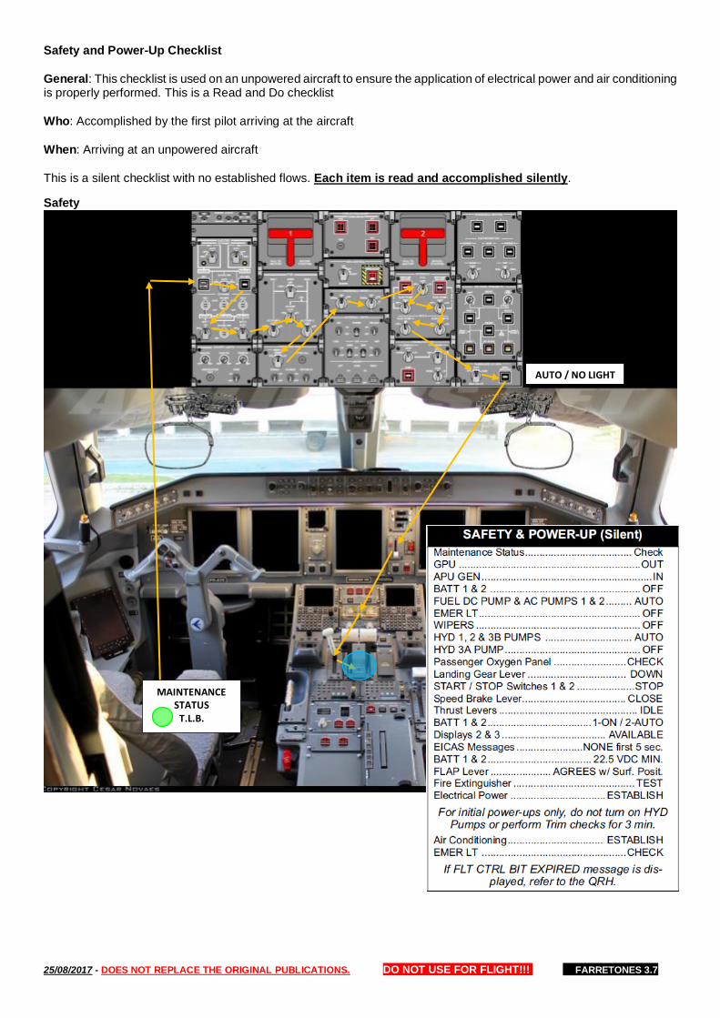
Safety and Power-Up Checklist
General: This checklist is used on an unpowered aircraft to ensure the application of electrical power and air conditioning is properly performed. This is a Read and Do checklist
Who: Accomplished by the first pilot arriving at the aircraft
When: Arriving at an unpowered aircraft
This is a silent checklist with no established flows. Each item is read and accomplished silently.
Safety
AUTO / NO LIGHT
MAINTENANCE STATUS
T.L.B.

25/08/2017 - DOES NOT REPLACE THE ORIGINAL PUBLICATIONS. DO NOT USE FOR FLIGHT!!! FARRETONES 3.7
Power-Up
BATT 1 & 2 22.5 MIN
EICAS MSG NONE 5sec
FIRE TEST:
-FIRE HANDLES IN -PUSHBUTTONS GUARDED -PUSH TEST: 6 LIGHTS OVERHEAD 5 MSG CAS
ENG 1 FIRE ENG 2 FIRE APU FIRE
CARGO FWD SMOKE CARGO AFT SMOKE
2 WARNING/ 2 FIRE ITT
GPU or APU EMER LT TEST: *CABIN CREW*
OFF -> ON CAS:
EMER LT ON EMER LT NOT ARMED
ON -> ARMED
25/08/2017 - DOES NOT REPLACE THE ORIGINAL PUBLICATIONS. DO NOT USE FOR FLIGHT!!! FARRETONES 3.7
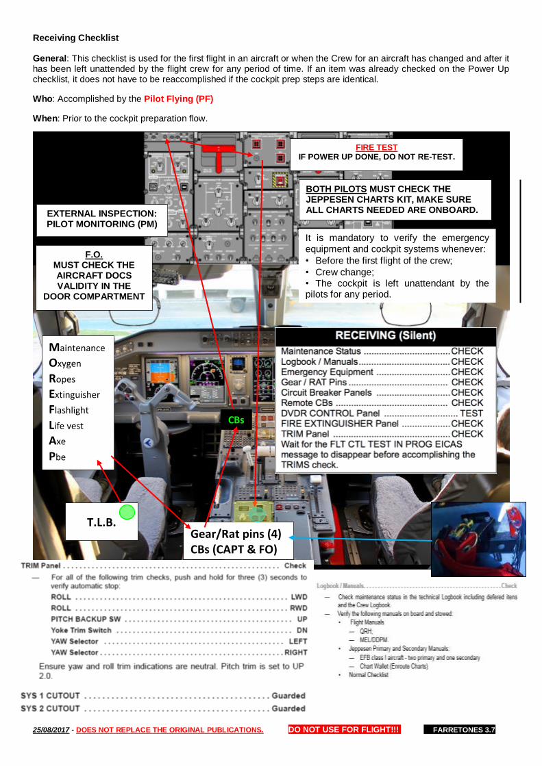
Receiving Checklist
General: This checklist is used for the first flight in an aircraft or when the Crew for an aircraft has changed and after it has been left unattended by the flight crew for any period of time. If an item was already checked on the Power Up checklist, it does not have to be reaccomplished if the cockpit prep steps are identical.
Who: Accomplished by the Pilot Flying (PF)
When: Prior to the cockpit preparation flow.
Maintenance
Oxygen
Ropes
Extinguisher
Flashlight
Life vest
Axe
Pbe
Gear/Rat pins (4) CBs (CAPT & FO)
FIRE TEST IF POWER UP DONE, DO NOT RE-TEST.
CBs
EXTERNAL INSPECTION: PILOT MONITORING (PM)
T.L.B.
F.O. MUST CHECK THE AIRCRAFT DOCS VALIDITY IN THE
DOOR COMPARTMENT
It is mandatory to verify the emergency equipment and cockpit systems whenever:
• Before the first flight of the crew; • Crew change; • The cockpit is left unattendant by the pilots for any period.
BOTH PILOTS MUST CHECK THE JEPPESEN CHARTS KIT, MAKE SURE ALL CHARTS NEEDED ARE ONBOARD.

25/08/2017 - DOES NOT REPLACE THE ORIGINAL PUBLICATIONS. DO NOT USE FOR FLIGHT!!! FARRETONES 3.7
Exterior Inspection
General: The exterior inspection, or walkaround, ensures the overall condition of the aircraft and its visible components and equipment are safe for flight.
Who: Accomplished by PM. When: This inspection must be accomplished before every flight
Procedures - Before beginning the inspection, review the Maintenance Log and if electrical power is not established,
complete the Power-up Checklist. Wear reflective vest (if not available report to Maint. and TLB). Prior to commencing
the inspection, turn on NAV lights and inspection lights at night. In case of adverse meteorological conditions, the
Captain can delegate the external inspection to the maintenance technician.
Conditions/Discrepancies - Verify the aircraft is acceptable for flight. Even though not noted individually, the aircraft and its visible components must be checked for the following:
— Proximate area is free of potential foreign object damage (FOD) items
— Customer walkway and boarding stairs are safe and clear
— Flight control surfaces are unobstructed and free from contamination
— Tire condition and pressure are acceptable
— All covers, plugs, picket/mooring lines removed
— All vents, pitot and static ports, intakes, and exhausts are not damaged or obstructed
— Pay attention to any evidence of fluid leaks from components, drains, panels, aircraft skin, and in ground vicinity
— Condition of aircraft structure or structural components: skin (visible damage) on Radome section, fuselage, wings, nacelles, pylons and empennage.
— All access panels and doors not actually involved in maintenance are secure
— Pitot static probes for evidence of freezing, severe discoloration, condition, and security
3 ENG COWL LATCH
In-Transit External Inspection
PM must check the wheels, tires,
brakes and surfaces.
25/08/2017 - DOES NOT REPLACE THE ORIGINAL PUBLICATIONS. DO NOT USE FOR FLIGHT!!! FARRETONES 3.7
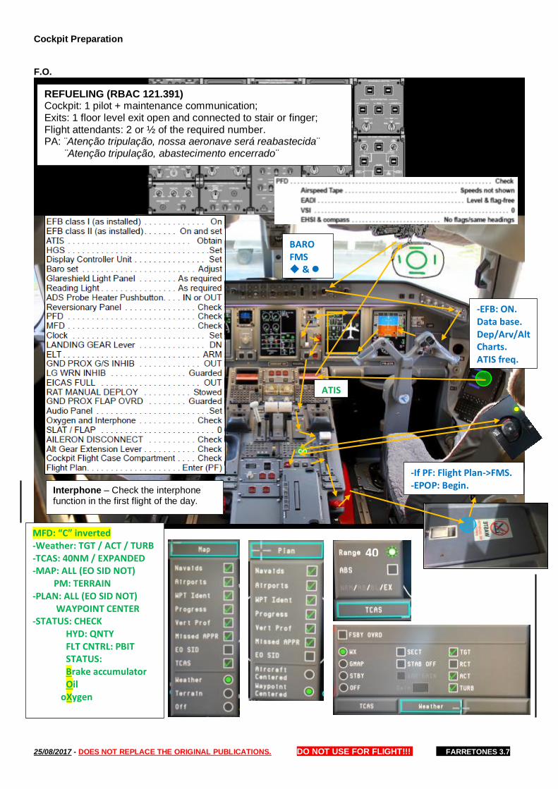
Cockpit Preparation
F.O.
-If PF: Flight Plan->FMS. -EPOP: Begin.
-EFB: ON. Data base. Dep/Arv/Alt Charts. ATIS freq.
BARO FMS &
ATIS
MFD: “C” inverted -Weather: TGT / ACT / TURB -TCAS: 40NM / EXPANDED -MAP: ALL (EO SID NOT) PM: TERRAIN -PLAN: ALL (EO SID NOT) WAYPOINT CENTER -STATUS: CHECK HYD: QNTY FLT CNTRL: PBIT STATUS: Brake accumulator Oil oXygen
40
REFUELING (RBAC 121.391) Cockpit: 1 pilot + maintenance communication; Exits: 1 floor level exit open and connected to stair or finger; Flight attendants: 2 or ½ of the required number. PA: ¨Atenção tripulação, nossa aeronave será reabastecida¨ ¨Atenção tripulação, abastecimento encerrado¨
Interphone – Check the interphone function in the first flight of the day.

25/08/2017 - DOES NOT REPLACE THE ORIGINAL PUBLICATIONS. DO NOT USE FOR FLIGHT!!! FARRETONES 3.7
CAPT
-If PF: Flight Plan->FMS. ->
-EFB: ON. Data base. Dep/Arv/Alt Charts. DOCS.
MFD: “C” inverted -Weather: TGT / ACT / TURB -TCAS: 40NM / EXPANDED -MAP: ALL (EO SID NOT) PM: TERRAIN -PLAN: ALL (EO SID NOT) WAYPOINT CENTER -STATUS: CHECK HYD: QNTY FLT CNTRL: PBIT STATUS: Brake accumulator Oil oXygen
----------OR----------
-ALT: _____ FT -SPD: FMS -SRC: PF SIDE -BARO -FMS ++
PA . . . . . . . . . . . . . . TEST Interphone CAB . . . . . TEST
REFUELING (RBAC 121.391) Cockpit: 1 pilot + maintenance communication; Exits: 1 floor level exit open and connected to stair or finger; Flight attendants: 2 or ½ of the required number. PA: ¨Atenção tripulação, nossa aeronave será reabastecida¨ ¨Atenção tripulação, abastecimento encerrado¨
25/08/2017 - DOES NOT REPLACE THE ORIGINAL PUBLICATIONS. DO NOT USE FOR FLIGHT!!! FARRETONES 3.7
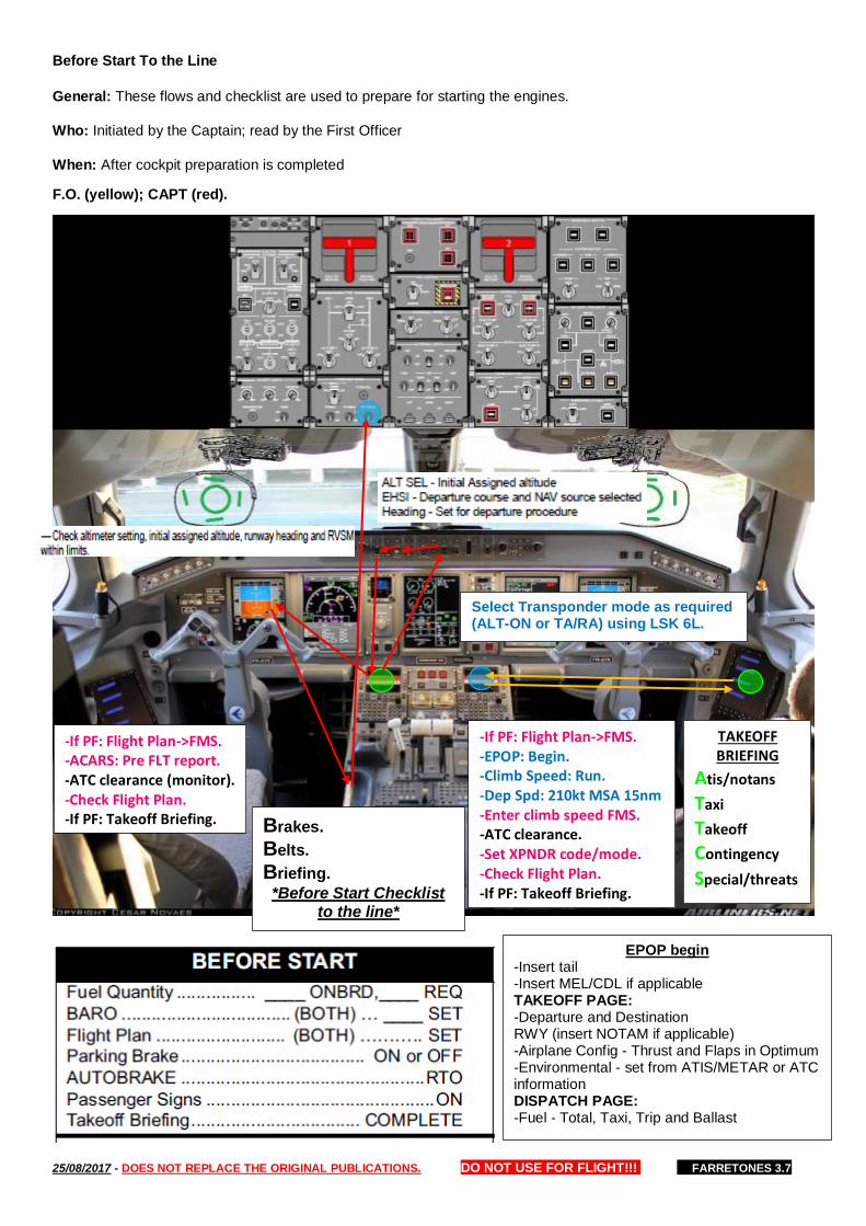
Before Start To the Line
General: These flows and checklist are used to prepare for starting the engines.
Who: Initiated by the Captain; read by the First Officer
When: After cockpit preparation is completed
F.O. (yellow); CAPT (red).
-If PF: Flight Plan->FMS. -EPOP: Begin. -Climb Speed: Run. -Dep Spd: 210kt MSA 15nm -Enter climb speed FMS. -ATC clearance. -Set XPNDR code/mode. -Check Flight Plan. -If PF: Takeoff Briefing.
-If PF: Flight Plan->FMS. -ACARS: Pre FLT report. -ATC clearance (monitor). -Check Flight Plan. -If PF: Takeoff Briefing. Brakes.
Belts.
Briefing.
*Before Start Checklist to the line*
TAKEOFF BRIEFING
Atis/notans
Taxi
Takeoff
Contingency
Special/threats
EPOP begin -Insert tail -Insert MEL/CDL if applicable TAKEOFF PAGE: -Departure and Destination RWY (insert NOTAM if applicable) -Airplane Config - Thrust and Flaps in Optimum -Environmental - set from ATIS/METAR or ATC information DISPATCH PAGE: -Fuel - Total, Taxi, Trip and Ballast
Select Transponder mode as required (ALT-ON or TA/RA) using LSK 6L.
25/08/2017 - DOES NOT REPLACE THE ORIGINAL PUBLICATIONS. DO NOT USE FOR FLIGHT!!! FARRETONES 3.7
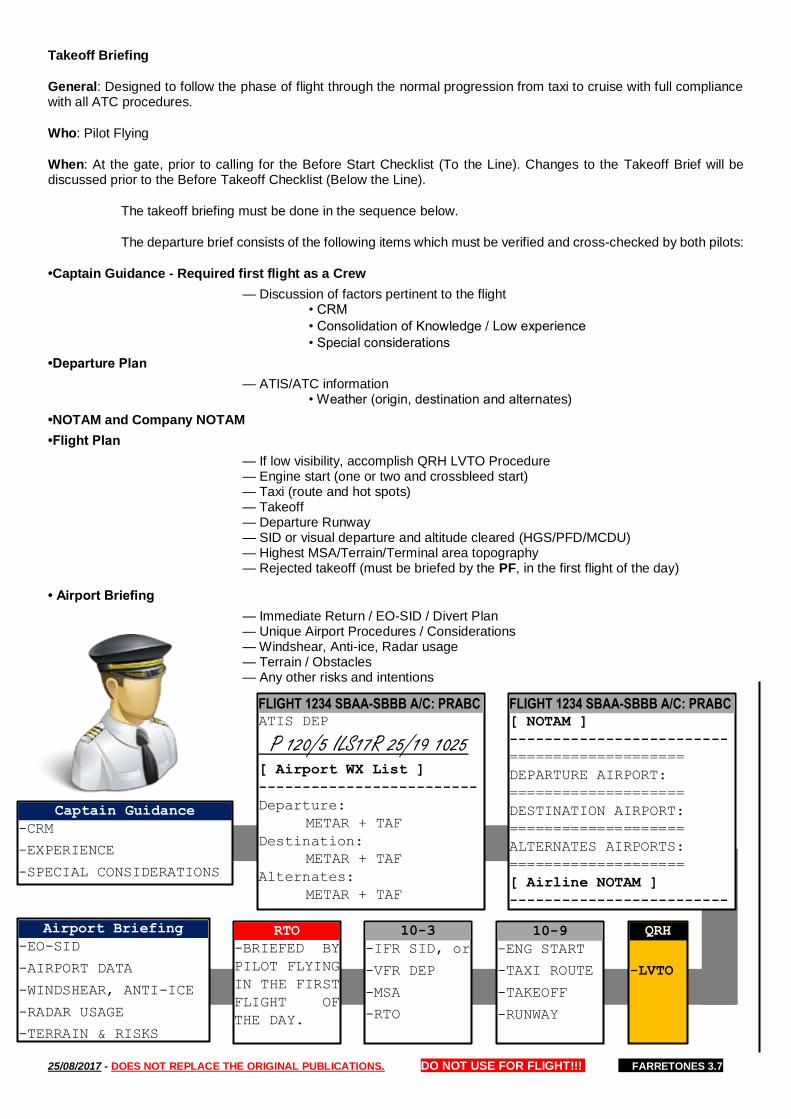
Takeoff Briefing
General: Designed to follow the phase of flight through the normal progression from taxi to cruise with full compliance with all ATC procedures.
Who: Pilot Flying
When: At the gate, prior to calling for the Before Start Checklist (To the Line). Changes to the Takeoff Brief will be discussed prior to the Before Takeoff Checklist (Below the Line).
The takeoff briefing must be done in the sequence below.
The departure brief consists of the following items which must be verified and cross-checked by both pilots:
•Captain Guidance - Required first flight as a Crew
— Discussion of factors pertinent to the flight • CRM
• Consolidation of Knowledge / Low experience
• Special considerations
•Departure Plan
— ATIS/ATC information • Weather (origin, destination and alternates)
•NOTAM and Company NOTAM
•Flight Plan
— If low visibility, accomplish QRH LVTO Procedure — Engine start (one or two and crossbleed start) — Taxi (route and hot spots) — Takeoff — Departure Runway — SID or visual departure and altitude cleared (HGS/PFD/MCDU) — Highest MSA/Terrain/Terminal area topography — Rejected takeoff (must be briefed by the PF, in the first flight of the day)
• Airport Briefing
— Immediate Return / EO-SID / Divert Plan — Unique Airport Procedures / Considerations — Windshear, Anti-ice, Radar usage — Terrain / Obstacles — Any other risks and intentions
FLIGHT 1234 SBAA-SBBB A/C: PRABC ATIS DEP
P 120/5 ILS17R 25/19 1025 [ Airport WX List ]
-------------------------
Departure:
METAR + TAF
Destination:
METAR + TAF
Alternates:
METAR + TAF
FLIGHT 1234 SBAA-SBBB A/C: PRABC [ NOTAM ]
-------------------------
====================
DEPARTURE AIRPORT:
====================
DESTINATION AIRPORT:
====================
ALTERNATES AIRPORTS:
====================
[ Airline NOTAM ]
-------------------------
10-9
-ENG START
-TAXI ROUTE
-TAKEOFF
-RUNWAY
10-3
-IFR SID, or
-VFR DEP
-MSA
-RTO
Airport Briefing
-EO-SID
-AIRPORT DATA
-WINDSHEAR, ANTI-ICE
-RADAR USAGE
-TERRAIN & RISKS
Captain Guidance
-CRM
-EXPERIENCE
-SPECIAL CONSIDERATIONS
QRH
-LVTO
RTO
-BRIEFED BY
PILOT FLYING
IN THE FIRST
FLIGHT OF
THE DAY.
25/08/2017 - DOES NOT REPLACE THE ORIGINAL PUBLICATIONS. DO NOT USE FOR FLIGHT!!! FARRETONES 3.7
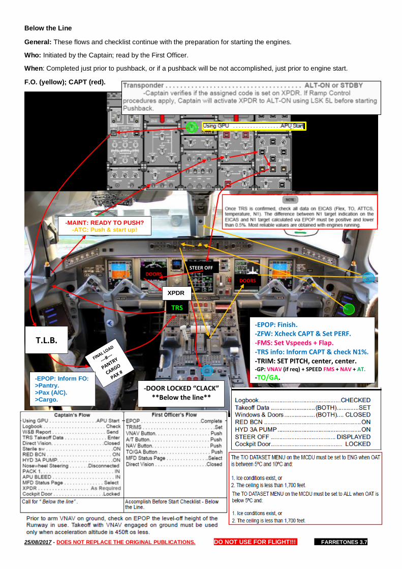
Below the Line
General: These flows and checklist continue with the preparation for starting the engines.
Who: Initiated by the Captain; read by the First Officer.
When: Completed just prior to pushback, or if a pushback will be not accomplished, just prior to engine start.
F.O. (yellow); CAPT (red).
-EPOP: Finish. -ZFW: Xcheck CAPT & Set PERF. -FMS: Set Vspeeds + Flap. -TRS info: Inform CAPT & check N1%. -TRIM: SET PITCH, center, center. -GP: VNAV (if req) + SPEED FMS + NAV + AT.
-TO/GA.
TRS
STEER OFF DOORS
-DOOR LOCKED “CLACK” **Below the line**
-MAINT: READY TO PUSH? -ATC: Push & start up!
DOORS
-EPOP: Inform FO: >Pantry. >Pax (A/C). >Cargo.
T.L.B.
XPDR
25/08/2017 - DOES NOT REPLACE THE ORIGINAL PUBLICATIONS. DO NOT USE FOR FLIGHT!!! FARRETONES 3.7
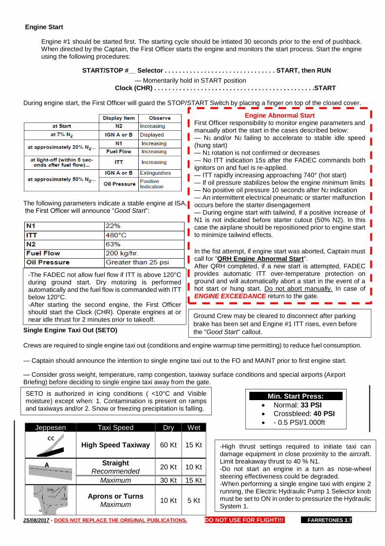
Engine Start
Engine #1 should be started first. The starting cycle should be intiated 30 seconds prior to the end of pushback. When directed by the Captain, the First Officer starts the engine and monitors the start process. Start the engine using the following procedures:
START/STOP #__ Selector . . . . . . . . . . . . . . . . . . . . . . . . . . . . . . . START, then RUN
— Momentarily hold in START position Clock (CHR) . . . . . . . . . . . . . . . . . . . . . . . . . . . . . . . . . . . . . . . . . . . . .START
During engine start, the First Officer will guard the STOP/START Switch by placing a finger on top of the closed cover.
The following parameters indicate a stable engine at ISA, the First Officer will announce “Good Start”:
Single Engine Taxi Out (SETO)
Crews are required to single engine taxi out (conditions and engine warmup time permitting) to reduce fuel consumption.
— Captain should announce the intention to single engine taxi out to the FO and MAINT prior to first engine start.
— Consider gross weight, temperature, ramp congestion, taxiway surface conditions and special airports (Airport Briefing) before deciding to single engine taxi away from the gate.
Engine Abnormal Start First Officer responsibility to monitor engine parameters and manually abort the start in the cases described below: — N1 and/or N2 failing to accelerate to stable idle speed (hung start) — N1 rotation is not confirmed or decreases — No ITT indication 15s after the FADEC commands both ignitors on and fuel is re-applied. — ITT rapidly increasing approaching 740° (hot start) — If oil pressure stabilizes below the engine minimum limits — No positive oil pressure 10 seconds after N2 indication — An intermittent electrical pneumatic or starter malfunction occurs before the starter disengagement — During engine start with tailwind, if a positive increase of N1 is not indicated before starter cutout (50% N2). In this case the airplane should be repositioned prior to engine start to minimize tailwind effects.
In the fist attempt, if engine start was aborted, Captain must call for "QRH Engine Abnormal Start". After QRH completed, if a new start is attempted, FADEC provides automatic ITT over-temperature protection on ground and will automatically abort a start in the event of a hot start or hung start. Do not abort manually. In case of ENGINE EXCEEDANCE return to the gate.
-The FADEC not allow fuel flow if ITT is above 120°C during ground start. Dry motoring is performed automatically and the fuel flow is commanded with ITT below 120°C. -After starting the second engine, the First Officer should start the Clock (CHR). Operate engines at or near idle thrust for 2 minutes prior to takeoff.
Ground Crew may be cleared to disconnect after parking
brake has been set and Engine #1 ITT rises, even before
the "Good Start" callout.
SETO is authorized in icing conditions ( <10°C and Visible moisture) except when: 1. Contamination is present on ramps and taxiways and/or 2. Snow or freezing precipitation is falling.
-High thrust settings required to initiate taxi can damage equipment in close proximity to the aircraft. Limit breakaway thrust to 40 % N1. -Do not start an engine in a turn as nose-wheel steering effectiveness could be degraded. -When performing a single engine taxi with engine 2 running, the Electric Hydraulic Pump 1 Selector knob must be set to ON in order to pressurize the Hydraulic System 1.
Min. Start Press:
• Normal: 33 PSI
• Crossbleed: 40 PSI
• - 0.5 PSI/1.000ft
Jeppesen Taxi Speed Dry Wet
High Speed Taxiway 60 Kt 15 Kt
Straight Recommended
20 Kt 10 Kt
Maximum 30 Kt 15 Kt
Aprons or Turns Maximum
10 Kt 5 Kt

25/08/2017 - DOES NOT REPLACE THE ORIGINAL PUBLICATIONS. DO NOT USE FOR FLIGHT!!! FARRETONES 3.7
Exterior lights
Use the table below to set exterior lights.
• When aircraft is stopped and parked the light selection can be done by the CA.
• During movement is done by the FO.
1. Only during the external inspection.
2. Captain´s discretion to leave strobe light off while in T/O position and hold if a distraction to other aircraft nearby may occur.
3. PF may request NOSE TAXI ON on final approach phase.
25/08/2017 - DOES NOT REPLACE THE ORIGINAL PUBLICATIONS. DO NOT USE FOR FLIGHT!!! FARRETONES 3.7
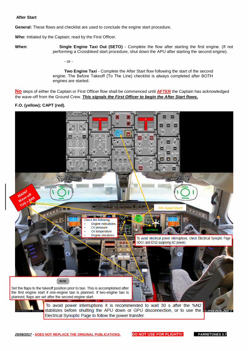
After Start
General: These flows and checklist are used to conclude the engine start procedure.
Who: Initiated by the Captain; read by the First Officer.
When: Single Engine Taxi Out (SETO) - Complete the flow after starting the first engine. (If not performing a Crossbleed start procedure, shut down the APU after starting the second engine).
- or -
Two Engine Taxi - Complete the After Start flow following the start of the second engine. The Before Takeoff (To The Line) checklist is always completed after BOTH engines are started.
No steps of either the Captain or First Officer flow shall be commenced until AFTER the Captain has acknowledged
the wave-off from the Ground Crew. This signals the First Officer to begin the After Start flows.
F.O. (yellow); CAPT (red).
-FO: Good Start!
ELECTRICAL

25/08/2017 - DOES NOT REPLACE THE ORIGINAL PUBLICATIONS. DO NOT USE FOR FLIGHT!!! FARRETONES 3.7
Before Takeoff
General: These flows and checklist is used to ensure the aircraft is ready for takeoff.
Who: Initiated by the Captain; read by the First Officer.
When: After BOTH engines are started and both pilots’ flows are complete.
F.O. (yellow); CAPT (red).
-“TAKE OFF OK!!!” **Before takeoff
checklist – to the line**
-FO: ENG#2: “Good start!” -After start check completed.
FLT CNTRL
-CAPT: Steering: Push down.
-FO: Ride the pedals: “Checked”
STATUS
MCDU: Ensure any late changes to the clearance are reflected in the FMS and radios.

25/08/2017 - DOES NOT REPLACE THE ORIGINAL PUBLICATIONS. DO NOT USE FOR FLIGHT!!! FARRETONES 3.7
Below the Line
Who: Initiated by Captain, read by First Officer
When: When cleared to the runway by ATC.
F.O. (yellow); CAPT (red).
-“ATC: Cleared to take off/line up.” **Below the line**
MFD MAP
MFD MAP
-FO: “Tripulação, preparar para decolagem”
-MFD: MAP.
-XPNDR: TA/RA.
-MFD: MAP.
MCDU -PF: FLT PLAN
-PM: RADIOS
“Runway Incursion, right side clear”
“Runway __, Left side clear”

25/08/2017 - DOES NOT REPLACE THE ORIGINAL PUBLICATIONS. DO NOT USE FOR FLIGHT!!! FARRETONES 3.7
Takeoff
Setting Takeoff Thrust
Once the aircraft is aligned with the runway center line, advance thrust levers to approximately 40% N1 and verify the engines are spooled. After the engines are stabilized (ITT decreases), PF advances the thrust levers to approximately 60° TLA confirm (A/T engagement or thrust levers in TOGA detent) and call "Check Thrust". PM verifies autothrottle engagement (TO & AT annunciates green and visually confirm thrust levers at TOGA detent), N1 is equal to target N1, ATTCS is displayed in green (except for item Engine Thrust), speed increasing and and call "Thrust Set, Airspeed Alive". At this moment Captain will guard the thrust levers. Any discrepancies should be announced. At 80 KIAS PM call " eighty knots" and PF "Checked". At this moment verify if ATTCS remains green. Once the “V1" takeoff callout is made, the Captain will let go of the thrust levers to indicate passing maximum reject speed.
-Check that the thrust levers are set to TOGA position before 60 kt, when HOLD mode is activated, even if the N1 has
already reached the takeoff thrust (N1 target). In this case the thrust levers can be advanced without increase in N1.
-If ATTCS remains white, PM must call "No ATTCS" and takeoff must be rejected.
-If “ENG TLA NOT TOGA” displayed on EICAS during TO or GA with the thrust levers out of the position TO/GA, throttles
must be advanced forward to the correct position (TO/GA) and FADEC will adjust power automatically.
Initial Steering
Keep the aircraft on the runway centerline using the rudder pedals. Be aware that initial direction control depends on the rudder pedals controlling the nose gear, and above 40-60 KIAS the rudder will became aerodynamically effective.
Normally the handwheel steering mode should not be used above normal taxi speeds (30 KIAS) and for takeoff roll.
Aft Center-of-Gravity Effects
Hold the control wheel slightly forward to improve nose wheel steering at aft CG.
Crosswind Takeoff
Directional deviations should be corrected immediately with smooth and positive control inputs. Control wheel inputs greater than 4° will increase drag due to spoiler deployment. The ailerons become effective as the aircraft accelerates through approximately 80 KIAS. Use aileron as needed to maintain wings level and rudder to maintain center line.
Rotation and Liftoff
At VR, rotate smoothly toward the target pitch attitude in one continuous motion. Use a rotation rate of approximately 2°
to 3° per second. High weights and temperatures or engine failure will require a lower rotation rate. After lift-off, and
once a positive rate of climb has been established, select landing gear UP.
Initial Climb
With all engines operating, adjust the pitch attitude to maintain V2 + 10 knots to the acceleration altitude. Continue as:
— FD Operative - Fly the flight director pitch commands. — FD Inoperative - Fly a maximum pitch attitude of 12°.
Clean-Up and Acceleration
At acceleration altitude, adjust the pitch attitude to maintain a slight climb rate while accelerating automatically to 210 KIAS (FMS speed set) and retract flaps at F-Speed. After Flaps and Slats are retracted, maintain 210 KIAS until reach MSA, than accelerate to normal enroute climb speed. It´s recommended 250KIAS until FL100, but if necessary and airspace classification allows speed can be increased. Flaps and Slats are considered retracted when SLAT/FLAP digital READOUT indication “0”
If the "F-BUG" disappears before total Slat/Flap retraction, retract Slat/Flap following Green Dot + 10 Kt.
To accomplish this, the DEP/APP SPEED should be set
on FMS to 210, 15NM and height adequate for the MSA.

25/08/2017 - DOES NOT REPLACE THE ORIGINAL PUBLICATIONS. DO NOT USE FOR FLIGHT!!! FARRETONES 3.7
Close-in turn after takeoff
When there is a need for a turn after takeoff for a divergent path in more of 180°, adopt the procedure with the smallest curve radius with the best climbing performance. A "Close-In Turn" should be initiated above 400ft AFE. The DEP/APP SPEED should be set on FMS to V2+10, or manual speed and appropriate altitude.
To set the Departure Speed go to page DEP/APP SPEED and
set V2+10kt, distance and height adequate for the procedure.
TO green
ATTCS green
Both speed tape alive PM: “Airspeed alive”

25/08/2017 - DOES NOT REPLACE THE ORIGINAL PUBLICATIONS. DO NOT USE FOR FLIGHT!!! FARRETONES 3.7
MGO – Dep VFR: Quando um procedimento de decolagem acontecer em um Circuito de Tráfego Visual, o piloto poderá optar por realizar as curvas conforme o padrão do circuito de tráfego do aeródromo, ou também pode escolher por subir na proa do eixo da pista e somente realizar curva após 2500 pés AFE de forma a interceptar a rota do voo.
ECS off Takeoff
On the MCDU Takeoff Data Set Menu the ECS ON or OFF option is displayed. Selecting ECS ON commands the ENG BLEED to remain ON and selecting ECS OFF commands the ENG BLEED to OFF until the first 500 ft AGL.
ECS off Takeoff Procedure
Packs Logic During Engine Start
When REF ECS is selected ON in the MCDU T/O DATASET MENU page, the caution EICAS message ENG REF
ECS DISAG may be temporarily displayed after both engines have started and are stabilized at idle.
In order to maintain the airplane pressurized during the initial 500 ft when ECS is selected to OFF the use of APU BLEED is recommended.
Following the procedure below, the ENG BLEED valves
will remain closed and the APU BLEED valve will supply
bleed air for PACKS operation during takeoff until 500 ft
AGL. If APU BLEED is unavailable the PACKS will remain
OFF until 500 ft AGL.
The APU bleed cannot be used for the anti-ice system
operation.
E5 ENG: When using TO-1 ► NO ATTCS
TO-3 ALLOWED
25/08/2017 - DOES NOT REPLACE THE ORIGINAL PUBLICATIONS. DO NOT USE FOR FLIGHT!!! FARRETONES 3.7
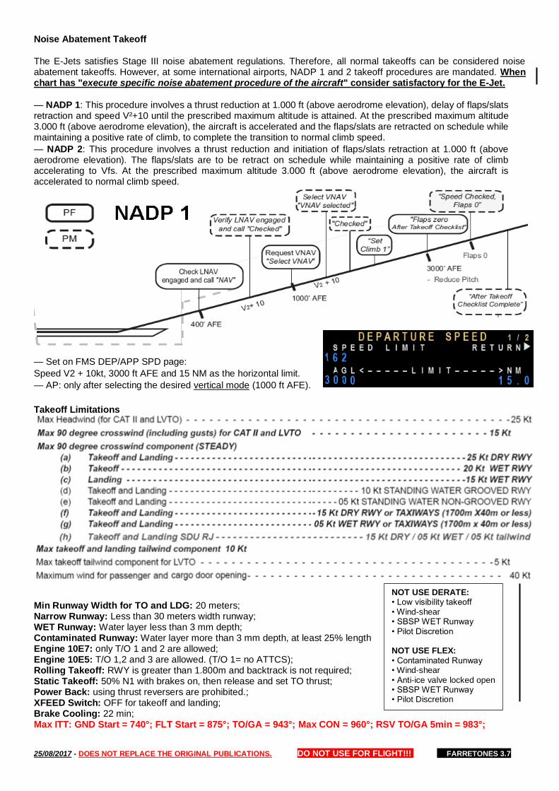
Noise Abatement Takeoff
The E-Jets satisfies Stage III noise abatement regulations. Therefore, all normal takeoffs can be considered noise abatement takeoffs. However, at some international airports, NADP 1 and 2 takeoff procedures are mandated. When chart has "execute specific noise abatement procedure of the aircraft" consider satisfactory for the E-Jet.
— NADP 1: This procedure involves a thrust reduction at 1.000 ft (above aerodrome elevation), delay of flaps/slats retraction and speed V²+10 until the prescribed maximum altitude is attained. At the prescribed maximum altitude 3.000 ft (above aerodrome elevation), the aircraft is accelerated and the flaps/slats are retracted on schedule while maintaining a positive rate of climb, to complete the transition to normal climb speed.
— NADP 2: This procedure involves a thrust reduction and initiation of flaps/slats retraction at 1.000 ft (above aerodrome elevation). The flaps/slats are to be retract on schedule while maintaining a positive rate of climb accelerating to Vfs. At the prescribed maximum altitude 3.000 ft (above aerodrome elevation), the aircraft is accelerated to normal climb speed.
— Set on FMS DEP/APP SPD page:
Speed V2 + 10kt, 3000 ft AFE and 15 NM as the horizontal limit.
— AP: only after selecting the desired vertical mode (1000 ft AFE).
Takeoff Limitations
Min Runway Width for TO and LDG: 20 meters; Narrow Runway: Less than 30 meters width runway; WET Runway: Water layer less than 3 mm depth; Contaminated Runway: Water layer more than 3 mm depth, at least 25% length Engine 10E7: only T/O 1 and 2 are allowed; Engine 10E5: T/O 1,2 and 3 are allowed. (T/O 1= no ATTCS); Rolling Takeoff: RWY is greater than 1.800m and backtrack is not required; Static Takeoff: 50% N1 with brakes on, then release and set TO thrust; Power Back: using thrust reversers are prohibited.; XFEED Switch: OFF for takeoff and landing; Brake Cooling: 22 min; Max ITT: GND Start = 740°; FLT Start = 875°; TO/GA = 943°; Max CON = 960°; RSV TO/GA 5min = 983°;
NOT USE DERATE: • Low visibility takeoff • Wind-shear • SBSP WET Runway • Pilot Discretion NOT USE FLEX: • Contaminated Runway • Wind-shear • Anti-ice valve locked open • SBSP WET Runway • Pilot Discretion
25/08/2017 - DOES NOT REPLACE THE ORIGINAL PUBLICATIONS. DO NOT USE FOR FLIGHT!!! FARRETONES 3.7
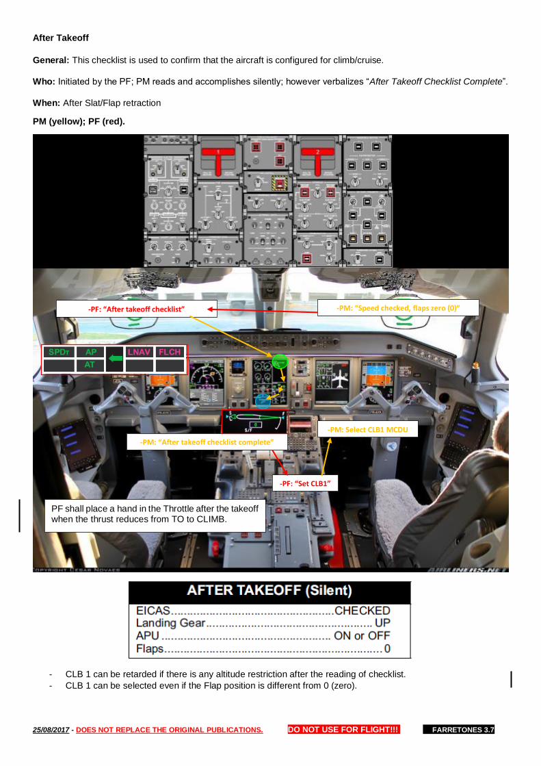
After Takeoff
General: This checklist is used to confirm that the aircraft is configured for climb/cruise.
Who: Initiated by the PF; PM reads and accomplishes silently; however verbalizes “After Takeoff Checklist Complete”.
When: After Slat/Flap retraction
PM (yellow); PF (red).
- CLB 1 can be retarded if there is any altitude restriction after the reading of checklist.
- CLB 1 can be selected even if the Flap position is different from 0 (zero).
-PM: “After takeoff checklist complete”
-PM: “Speed checked, flaps zero (0)” -PF: “After takeoff checklist”
-PF: “Set CLB1”
-PM: Select CLB1 MCDU
PF shall place a hand in the Throttle after the takeoff when the thrust reduces from TO to CLIMB.

25/08/2017 - DOES NOT REPLACE THE ORIGINAL PUBLICATIONS. DO NOT USE FOR FLIGHT!!! FARRETONES 3.7
Climb
Altitude selection Guidance Panel: At or Below constrains must be set on the Guidance Panel. When within 5 NM and 2.000ft of other aircraft, reduce the rate of climb to 1.000 fpm to avoid the generation of TAs and RAs.
Climb Speed Determination: Maintain flaps-up maneuvering speed until passing MSA or to clear convective zones.
Maneuvering: If considerable maneuvering is required during the departure, the flaps-up maneuvering speed is recommended until the maneuvering phase is complete and the aircraft is enroute toward the destination.
Climb Thrust: The power will be set automatically when passing the acceleration altitude, if selected prior to departure. If not selected, set VNAV passing the acceleration altitude. The Engines have two modes of climb thrust:
— CLB-1: Maximum Available Climb Thrust;
— CLB-2: Reduced Climb Thrust at sea level, approximately 90% of Maximum Climb Thrust at sea level.
Transition Altitude
These flows are used to set the altimeters to 1013 hPa.
Who: Initiated by the PF.
When: Transition altitude.
PM (yellow); PF (red).
Climb Speed Schedule:
1- 250 KIAS or greater if desired and airspace classification allows.
2-Maintain VFS + 50kt until intercepting Mach
0.60 or green dot speed, whichever is higher,
following this until level off.
PF “Transition, Standard”
PM “Standard”
"Passing FLxxx, now”.
"Cross Checked or minus / plus xx ft”
Max Diference = 100 ft
STD
STD
STD

25/08/2017 - DOES NOT REPLACE THE ORIGINAL PUBLICATIONS. DO NOT USE FOR FLIGHT!!! FARRETONES 3.7
FL 100
These flows are used to configure the aircraft’s exterior lights for cruise and notify the Cabin Crew the flight is leaving the sterile cockpit environment. There is no checklist.
Who: Initiated by PF
When: Leaving FL 100 or 10.000 if Transition Altitude is above FL100 or at cruise level below FL100.
For airports with elevation above 5.000ft, consider FL 150 instead of FL 100.
PM (yellow); PF (red).
MCDU PROG Page - Clear any remotely tuned navaids. RADIO Page - Clear any DME Holds. FIX INFO - Clear any fix inserted.
FL100 -PF: “One zero zero”
OPTM CRZ ALT
-MAP: WX
Conditions depending, the Captain will turn off the FSTN BELTS as his discretion, even below FL 100.
FL100
NEW CRUISE ALTITUDE If a new cruise altitude is required: Optimum CRZ ALT Table…………Check ATC……………….……..Request new FL ALT SEL……………...……….Set new FL MCDU…………………………Set new FL Climb Speed……….Check QRH – PERF MCDU……………..Set new Climb Speed

25/08/2017 - DOES NOT REPLACE THE ORIGINAL PUBLICATIONS. DO NOT USE FOR FLIGHT!!! FARRETONES 3.7
Cruise
These flows ensures aircraft systems are checked once level at cruise altitude, an initial fuel check conducted, and
wind entries completed if desired. Workload permitting, these duties should be completed as assigned after level off;
however, both pilots should actively monitor these items during the flight.
PM (yellow); PF (red).
Flight Progress:
Pilot Flying: Destination and alternates weather conditions (ACARS and VOLMET). — Manage the optimum flight level considering best fuel consumption, wind and turbulence; — Flight Monitoring: After the first flight hour ACARS free text message must be sent with the following information: LAST WAYPOINT+TIME OVER_DESTINATION+ETA Exemple: FERMA1003 SSA1103 After the first message, last position and ETA must be updated every two hours of flight. Whenever a "direct to" is used last way point information is missed, in this case the message must sent with NEXT WAYPOINT+ETO... Changes in ETA greater than 10 minutes, message should be updated. Pilot Monitoring: The following items must be monitored in accordance with the Flight Release: — Time — Fuel: For flights shorter than 90 min, OFP must be crosschecked with actual performance and deviations must be noted for TOC and TOD. For flights greater than 90 min, OFP must be crosschecked with actual performance and deviations must be noted for TOC and every 1 hour of flight time. — Grid MORA; — ATC frequency boundaries; MGO: During Cruise Flight, both pilots shall check: • Aircraft Cruise level flight and RVSM procedures; • Cruise Speed stabilization as the SOP or ATC; • Weather Radar Tilt ajustment; • Fuel Balance – do only Fuel Balance during cruise flight; • Aircraft trimming; • Aircraft systems working properlly; • Real Fuel comsuption compared to the navigation, for each flight hour; • For flights over 90 minutes, shall be performed the navigation calculations. Check the ETA and estimate fuel at arrival with the information provided by the FMS. Every 60 minutes check the ATO and AFRM at the next fix. • For flights less than 90 minutes, shall be performed the navigation calculations for the arrival fuel at the TOC and TOD; • The Grid Mora of the flight sector shall be checked during all cruise flight.
Altimeters RVSM 200 FT MAX NON RVSM 300FT MAX
ALL PAGES -EVERY HOUR-
CRZ - 90 SEC
PF: “ASEL”, “ALT”
Speed LRC or ATC
FLIGHT PROGRESS
CHART OPEN ON FLIGHT SECTOR
Oxigen Requirements
ALT REQ
Until FL100 Only Air
FL100 to FL337 Air-Oxigen Mix
FL337 to FL400 100% Oxigen
Above FL400 100% Oxigen Pressurized
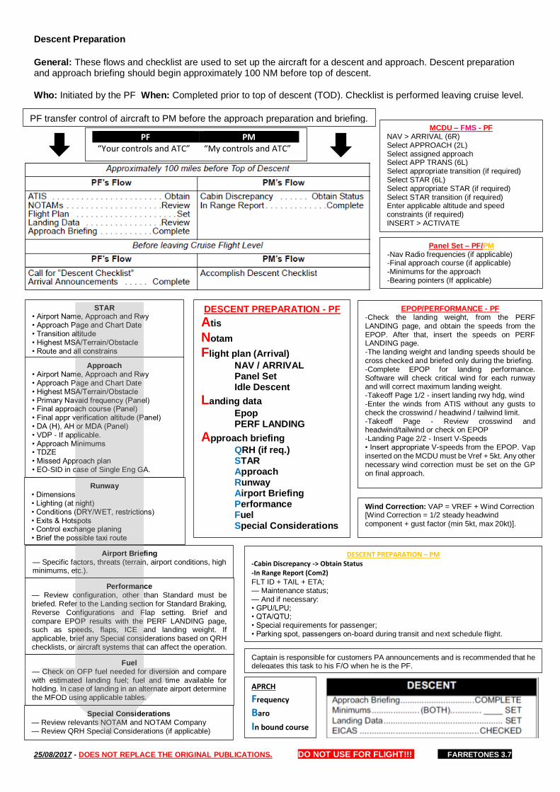
25/08/2017 - DOES NOT REPLACE THE ORIGINAL PUBLICATIONS. DO NOT USE FOR FLIGHT!!! FARRETONES 3.7
Descent Preparation
General: These flows and checklist are used to set up the aircraft for a descent and approach. Descent preparation and approach briefing should begin approximately 100 NM before top of descent.
Who: Initiated by the PF When: Completed prior to top of descent (TOD). Checklist is performed leaving cruise level.
DESCENT PREPARATION – PM -Cabin Discrepancy -> Obtain Status -In Range Report (Com2) FLT ID + TAIL + ETA; — Maintenance status; — And if necessary: • GPU/LPU; • QTA/QTU; • Special requirements for passenger; • Parking spot, passengers on-board during transit and next schedule flight.
DESCENT PREPARATION - PF
Atis
Notam
Flight plan (Arrival)
NAV / ARRIVAL Panel Set Idle Descent
Landing data
Epop PERF LANDING
Approach briefing
QRH (if req.) STAR Approach Runway Airport Briefing Performance Fuel Special Considerations
APRCH
Frequency
Baro
In bound course
PF transfer control of aircraft to PM before the approach preparation and briefing. MCDU – FMS - PF
NAV > ARRIVAL (6R) Select APPROACH (2L) Select assigned approach Select APP TRANS (6L) Select appropriate transition (if required) Select STAR (6L) Select appropriate STAR (if required) Select STAR transition (if required) Enter applicable altitude and speed constraints (if required) INSERT > ACTIVATE
Panel Set – PF/PM -Nav Radio frequencies (if applicable) -Final approach course (if applicable) -Minimums for the approach -Bearing pointers (If applicable)
EPOP/PERFORMANCE - PF -Check the landing weight, from the PERF LANDING page, and obtain the speeds from the EPOP. After that, insert the speeds on PERF LANDING page. -The landing weight and landing speeds should be cross checked and briefed only during the briefing. -Complete EPOP for landing performance. Software will check critical wind for each runway and will correct maximum landing weight. -Takeoff Page 1/2 - insert landing rwy hdg, wind -Enter the winds from ATIS without any gusts to check the crosswind / headwind / tailwind limit. -Takeoff Page - Review crosswind and headwind/tailwind or check on EPOP -Landing Page 2/2 - Insert V-Speeds • Insert appropriate V-speeds from the EPOP. Vap inserted on the MCDU must be Vref + 5kt. Any other necessary wind correction must be set on the GP on final approach.
Captain is responsible for customers PA announcements and is recommended that he delegates this task to his F/O when he is the PF.
PF PM “Your controls and ATC” “My controls and ATC”
STAR • Airport Name, Approach and Rwy • Approach Page and Chart Date • Transition altitude • Highest MSA/Terrain/Obstacle • Route and all constrains
Approach • Airport Name, Approach and Rwy • Approach Page and Chart Date • Highest MSA/Terrain/Obstacle • Primary Navaid frequency (Panel) • Final approach course (Panel) • Final appr verification altitude (Panel) • DA (H), AH or MDA (Panel) • VDP - If applicable. • Approach Minimums • TDZE • Missed Approach plan • EO-SID in case of Single Eng GA.
Runway • Dimensions • Lighting (at night) • Conditions (DRY/WET, restrictions) • Exits & Hotspots • Control exchange planing • Brief the possible taxi route
Airport Briefing — Specific factors, threats (terrain, airport conditions, high minimums, etc.).
Performance — Review configuration, other than Standard must be briefed. Refer to the Landing section for Standard Braking, Reverse Configurations and Flap setting. Brief and compare EPOP results with the PERF LANDING page, such as speeds, flaps, ICE and landing weight. If applicable, brief any Special considerations based on QRH checklists, or aircraft systems that can affect the operation.
Fuel — Check on OFP fuel needed for diversion and compare with estimated landing fuel; fuel and time available for holding. In case of landing in an alternate airport determine the MFOD using applicable tables.
Special Considerations — Review relevants NOTAM and NOTAM Company — Review QRH Special Considerations (if applicable)
Wind Correction: VAP = VREF + Wind Correction [Wind Correction = 1/2 steady headwind component + gust factor (min 5kt, max 20kt)].

25/08/2017 - DOES NOT REPLACE THE ORIGINAL PUBLICATIONS. DO NOT USE FOR FLIGHT!!! FARRETONES 3.7
Descent
PM (yellow); PF (red).
Idle Descent example in the MCDU:
PF: “Descent Checklist”
Leaving Cruise Level
PM: Reads Descent Checklist Approach Briefing
“XXXX BARO/RA Set” “XXXX BARO/RA Set”
LANDING DATA
Speedbrakes: -Limit the use to half extension for passenger comfort whenever possible; -Keep a hand on the lever, except while performing other specific function; -Use in disagreement with thrust, speed configuration, or considered critical to safety, PM state "check speedbrake" and PF close and state "speedbrake closed".
Plan all descents to arrive at traffic pattern altitude at flaps-up maneuvering speed:
— 12 miles out for a straight-in approach
— 8 miles out for an abeam approach.
A good crosscheck is to be at 10000 ft AGL, 30 miles from the airport at 250 kt.
During descent (At or Above) constrains must be set on the Guidance Panel.
During descent, when operating within 5 NM and 2.000ft of other aircraft, reduce the rate of descent to 1.000 fpm to avoid the generation of TAs and RAs.
Headwinds = steeper flight path angles Tailwinds = small flight path angles
Captain shall select ILS in the
IESS during ILS APP

25/08/2017 - DOES NOT REPLACE THE ORIGINAL PUBLICATIONS. DO NOT USE FOR FLIGHT!!! FARRETONES 3.7
-The feature early descent (descent now) should be avoided. -If the STALL PROT ICE SPEED message is present, or icing conditions are anticipated on any portion of the arrival or approach, check on QRH Performance, the correct table for Anti-ice ON or set in the Idle Descent Software. -To decelerate using VNAV PTH or FPA, it’s recommended to determine a point during the descent, close to FL120.
From this point the angle should be reduced in about 1°.
Descida por Instrumentos em Locais Desprovidos de Órgãos de Controle de Tráfego Aéreo [Ref.: ICA 100-37]
Aeronaves voando sob as regras de voo por instrumento (IFR) fora de espaço aéreo controlado deverá: Obter do ACC, diretamente ou através de uma estação de telecomunicações aeronáuticas, a autorização para iniciar a descida e adotar um dos procedimentos descritos nas subalíneas abaixo para definir o nível ou altitude mínimo de descida até o auxílio à navegação/fixo balizador da MSA/TAA do procedimento: • manter o nível de cruzeiro; • descer até o nível mínimo da FIR; • descer até o limite inferior da MSA/TAA, previsto na IAC, após cruzar o limite lateral da citada MSA/TAA; ou • descer sob sua responsabilidade até o limite inferior da MSA/TAA, se encontrar VMC; • Obter da estação de telecomunicações aeronáuticas local as informações necessárias para a aproximação e pouso; • Continuar a descida em órbita e iniciar o procedimento de aproximação por instrumentos para a pista selecionada; e • Transmitir na frequência do órgão AFIS local, durante a descida, os níveis ou altitudes e as fases sucessivas do procedimento que foram atingidos. • De acordo com a ICA 100-37, toda aeronave que operar no espaço aéreo inferior num raio de 27NM (50km) do aeródromo que esteja sendo prestado o AFIS deverá manter a escuta do órgão responsável por esse serviço para coordenação e informação do voo. • Conforme exposto acima, nas operações fora de espaço aéreo controlado é prevista a descida até os mínimos da terminal (TAA/MSA) publicados nas cartas dos procedimentos IFR (ILS/RNAV/VOR/NDB), após cruzar o limite lateral destas áreas, mesmo em condições IMC.
Razão de Descida
Quando voando abaixo de 5.000ft os Pilotos deverão evitar a utilização de razões de descida elevadas*. Uma boa referência é considerar como razão máxima a metade da diferença entre a altitude inicial e a pretendida: • 5.000ft para 2.000ft – razão máxima de 1.500 fpm; • 3.000ft para 2.000ft – razão máxima de 500 fpm. *(E-JET) - O uso do modo FLCH deve ser evitado nestes casos. Abaixo da MSA manter razão de descida máxima de 2500fpm.
Holding Speeds Tables – DOC8168
LEVEL NORMAL TURBULENCE T
able
IV
-1-1
IC
AO
0 – 14.000 ft 230 KT 280 KT
14.001 – 20.000 ft 240 KT 280 KT or MACH 0.80
20.001 – 34.000 ft 265 KT
Above 34.001 ft MACH 0.83 MACH 0.83
LEVEL PROP JET
Table
IV
-1-2
PA
NS
O
PS
NORMAL TURBULENCE
0 – 6.000 ft 170 KT 210 KT
280 KT or MACH 0.80 6.001 – 14.000 ft 170 KT 220 KT
Above 14.001 ft 175 KT 240 KT
LEVEL ALL AIRCRAFT
Table
IV
-1-3
F
AA
At or Below 14.000 ft 01:00 Leg
Above 14.000 ft 01:30 Leg
0 – 6.000 ft 200 KT
6.001 – 14.000 ft 230 KT
Above 14.001 ft 265 KT
If necessary to change the altitude during hold, use 500 – 1000 ft/min rate, or ATC request.
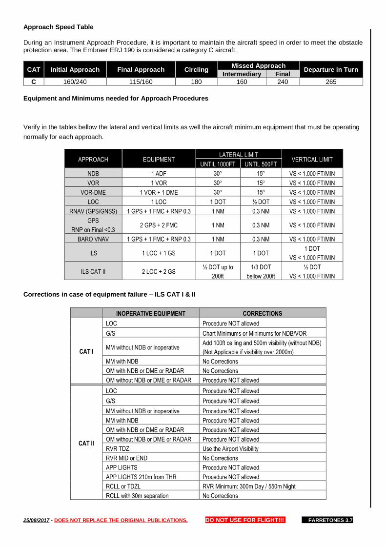
25/08/2017 - DOES NOT REPLACE THE ORIGINAL PUBLICATIONS. DO NOT USE FOR FLIGHT!!! FARRETONES 3.7
Approach Speed Table
During an Instrument Approach Procedure, it is important to maintain the aircraft speed in order to meet the obstacle protection area. The Embraer ERJ 190 is considered a category C aircraft.
CAT Initial Approach Final Approach Circling Missed Approach
Departure in Turn Intermediary Final
C 160/240 115/160 180 160 240 265
Equipment and Minimums needed for Approach Procedures
Verify in the tables bellow the lateral and vertical limits as well the aircraft minimum equipment that must be operating
normally for each approach.
APPROACH EQUIPMENT LATERAL LIMIT
VERTICAL LIMIT UNTIL 1000FT UNTIL 500FT
NDB 1 ADF 30 15 VS < 1.000 FT/MIN
VOR 1 VOR 30 15 VS < 1.000 FT/MIN
VOR-DME 1 VOR + 1 DME 30 15 VS < 1.000 FT/MIN
LOC 1 LOC 1 DOT ½ DOT VS < 1.000 FT/MIN
RNAV (GPS/GNSS) 1 GPS + 1 FMC + RNP 0.3 1 NM 0.3 NM VS < 1.000 FT/MIN
GPS
RNP on Final <0.3 2 GPS + 2 FMC 1 NM 0.3 NM VS < 1.000 FT/MIN
BARO VNAV 1 GPS + 1 FMC + RNP 0.3 1 NM 0.3 NM VS < 1.000 FT/MIN
ILS 1 LOC + 1 GS 1 DOT 1 DOT 1 DOT
VS < 1.000 FT/MIN
ILS CAT II 2 LOC + 2 GS ½ DOT up to
200ft
1/3 DOT
bellow 200ft
½ DOT
VS < 1.000 FT/MIN
Corrections in case of equipment failure – ILS CAT I & II
INOPERATIVE EQUIPMENT CORRECTIONS
CAT I
LOC Procedure NOT allowed
G/S Chart Minimums or Minimums for NDB/VOR
MM without NDB or inoperative Add 100ft ceiling and 500m visibility (without NDB)
(Not Applicable if visibility over 2000m)
MM with NDB No Corrections
OM with NDB or DME or RADAR No Corrections
OM without NDB or DME or RADAR Procedure NOT allowed
CAT II
LOC Procedure NOT allowed
G/S Procedure NOT allowed
MM without NDB or inoperative Procedure NOT allowed
MM with NDB Procedure NOT allowed
OM with NDB or DME or RADAR Procedure NOT allowed
OM without NDB or DME or RADAR Procedure NOT allowed
RVR TDZ Use the Airport Visibility
RVR MID or END No Corrections
APP LIGHTS Procedure NOT allowed
APP LIGHTS 210m from THR Procedure NOT allowed
RCLL or TDZL RVR Minimum: 300m Day / 550m Night
RCLL with 30m separation No Corrections
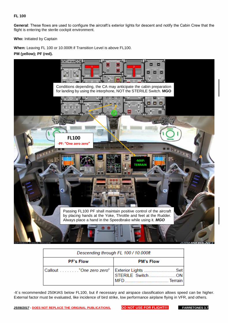
25/08/2017 - DOES NOT REPLACE THE ORIGINAL PUBLICATIONS. DO NOT USE FOR FLIGHT!!! FARRETONES 3.7
FL 100
General: These flows are used to configure the aircraft’s exterior lights for descent and notify the Cabin Crew that the flight is entering the sterile cockpit environment.
Who: Initiated by Captain
When: Leaving FL 100 or 10.000ft if Transition Level is above FL100.
PM (yellow); PF (red).
-It´s recommended 250KIAS below FL100, but if necessary and airspace classification allows speed can be higher.
External factor must be evaluated, like incidence of bird strike, low performance airplane flying in VFR, and others.
FL100 -PF: “One zero zero”
-MAP: TERRAIN
Conditions depending, the CA may anticipate the cabin preparation for landing by using the interphone, NOT the STERILE Switch. MGO
Passing FL100 PF shall maintain positive control of the aircraft by placing hands at the Yoke, Throttle and feet at the Rudder. Always place a hand in the Speedbrake while using it. MGO

25/08/2017 - DOES NOT REPLACE THE ORIGINAL PUBLICATIONS. DO NOT USE FOR FLIGHT!!! FARRETONES 3.7
Transition Level
PF will call “One zero one five twice set”. The Captain is required to announce “twice” on the altimeter callout to verify that the PFD and IESS altimeter settings are set. Callout: "Transition (setting)"
When changing altimeters setting crosscheck the primary barometric altimeters against one another. Executing Baro-VNAV procedure the difference between the altimeter indications must not exceed ±100ft. If the difference exceeds ±100 ft, the approach may be continued with LNAV minimums only. Callout: PF will call when passing the IAF “Passing Five thousand five hundred now”.
Callout: PM will confirm and call “Cross-checked” or “plus/minus XXft”.
After the Seat Belts ON - Call for "Approach Checklist"
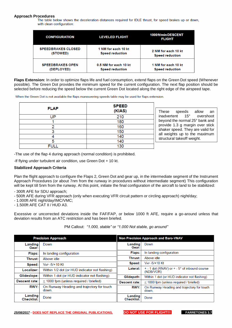
25/08/2017 - DOES NOT REPLACE THE ORIGINAL PUBLICATIONS. DO NOT USE FOR FLIGHT!!! FARRETONES 3.7
Approach Procedures
Flaps Extension: In order to optimize flaps life and fuel consumption, extend flaps on the Green Dot speed (Whenever possible). The Green Dot provides the minimum speed for the current configuration. The next flap position should be selected before reducing the speed below the current Green Dot located along the right edge of the airspeed tape.
-The use of the flap 4 during approach (normal condition) is prohibited.
-If flying under turbulent air condition, use Green Dot + 10 kt.
Stabilized Approach Criteria
Plan the flight approach to configure the Flaps 2, Green Dot and gear up, in the intermediate segment of the Instrument Approach Procedures (or about 7nm from the runway in procedures without intermediate segment) This configuration will be kept till 5nm from the runway. At this point, initiate the final configuration of the aircraft to land to be stabilized:
- 300ft AFE for SDU approach; - 500ft AFE during VFR approach (only when executing VFR circuit pattern or circling approach) night/day; - 1.000ft AFE night/day/IMC/VMC; - 1.500ft AFE CAT II / HUD A3. Excessive or uncorrected deviations inside the FAF/FAP, or below 1000 ft AFE, require a go-around unless that deviation results from an ATC restriction and has been briefed.
PM Callout: “1.000, stable” or “1.000 Not stable, go around”
These speeds allow an inadvertent 15° overshoot beyond the normal 25° bank and provide 1.3 g margin over stick shaker speed. They are valid for all weights up to the maximum structural takeoff weight.
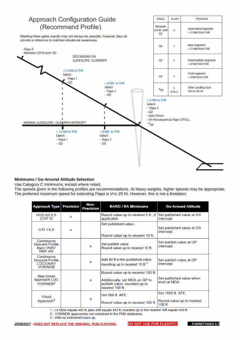
25/08/2017 - DOES NOT REPLACE THE ORIGINAL PUBLICATIONS. DO NOT USE FOR FLIGHT!!! FARRETONES 3.7
Minimums / Go-Around Altitude Selection
Use Category C minimums, except where noted. The speeds given in the following profiles are recommendations. At heavy weights, higher speeds may be appropriate. The preferred maximum speed for extending Flaps is VFE-20 Kt. However, this is not a limitation;
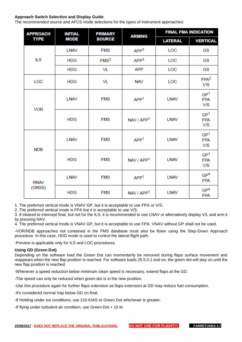
25/08/2017 - DOES NOT REPLACE THE ORIGINAL PUBLICATIONS. DO NOT USE FOR FLIGHT!!! FARRETONES 3.7
Approach Switch Selection and Display Guide
The recommended source and AFCS mode selections for the types of instrument approaches:
1. The preferred vertical mode is VNAV GP, but it is acceptable to use FPA or V/S. 2. The preferred vertical mode is FPA but it is acceptable to use V/S. 3. If cleared to intercept final, but not for the ILS, it is recommended to use LNAV or alternatively display V/L and arm it by pressing NAV. 4. The preferred vertical mode is VNAV GP, but it is acceptable to use FPA. VNAV without GP shall not be used.
-VOR/NDB approaches not contained in the FMS database must also be flown using the Step-Down Approach procedure. In this case, HDG mode is used to control the lateral flight path.
-Preview is applicable only for ILS and LOC procedures.
Using GD (Green Dot)
Depending on the software load the Green Dot can momentarily be removed during flaps surface movement and reappears when the new flap position is reached. For software loads 25.5.0.1 and on, the green dot will stay on until the new flap position is reached.
-Whenever a speed reduction below minimum clean speed is necessary, extend flaps at the GD.
-The speed can only be reduced when green dot is in the new position.
-Use this procedure again for further flaps extension as flaps extension at GD may reduce fuel consumption.
-It's considered normal Vap below GD on final.
-If Holding under ice conditions, use 210 KIAS or Green Dot whichever is greater.
-If flying under turbulent air condition, use Green Dot + 10 kt.
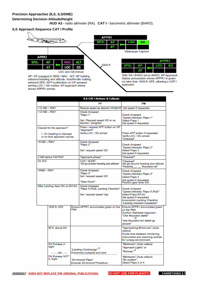
25/08/2017 - DOES NOT REPLACE THE ORIGINAL PUBLICATIONS. DO NOT USE FOR FLIGHT!!! FARRETONES 3.7
Precision Approaches (ILS, ILS/DME)
Determining Decision Altitude/Height
HUD A3 - radio altimeter (RA). CAT I - barometric altimeter (BARO).
ILS Approach Sequence CAT I Profile

25/08/2017 - DOES NOT REPLACE THE ORIGINAL PUBLICATIONS. DO NOT USE FOR FLIGHT!!! FARRETONES 3.7
BARO VNAV The final approach path vertical angle (VPA) is safeguarded against the effects of low temperature by the design of the procedure.
-The Baro-VNAV can not be executed with temporary displaced threshold.
-The use of Temperature Compensation is not authorized.
-Remote altimeter settings are not allowed.

25/08/2017 - DOES NOT REPLACE THE ORIGINAL PUBLICATIONS. DO NOT USE FOR FLIGHT!!! FARRETONES 3.7
Non-Precision Approach
When the weather is below 1500 ft/5 km, the autopilot will be used from at least the FAF/FAP until:
— Leveling at MDA;
— 40 ft above the MDA with a continuous descent flight path;
— Until a “Landing” call is made during non-precision approaches.
If the weather is above these minimums, the use of the autopilot is at the pilots discretion. Use of the autopilot reduces Crew workload with respect to flight path control, and allows more time for management and monitoring of the approach.
-To use GP is necessary to check if the angle after FAF is in capital letters.
-If the outbound leg is time-based, use green dot speed.
-The use of FLCH inside the FAF/FAP is prohibited.
VOR/NDB approaches not contained in the FMS database must also be flown using the continuous descent flight angle procedure with appropriate angle. In this case, HDG mode is used to control the lateral flight path.
Display Controller Panel and Bearing Pointers Selection
Setting Minimums
For all LOC approaches when the published MDA is not a multiple off 100 ft, round it up to the next 100 ft. (i.e 660ft is rounded up to 700 ft). When setting MDA, set ajusted MDA in BARO MINIMUMS on PFD. This number now becomes the "new" MDA fot the approach.
For RNAV (LNAV only), VOR and NDB approaches with continuous descent profile, add 40 ft in the published value and round up to nearst 10 ft. Set the “adjusted” MDA in the BARO MINIMUMS on the PFD.
TCS permits the aircraft to fly through the selected altitude. The use of TCS is prohibited when conducting an instrument approach in weather below 1000 ft./5 km.
Calculated VDP - The purpose of determining a ‘calculated’ VDP is to validate that the aircraft is at the proper position on the approach corresponding to the point of intercept with a 3° profile to the touchdown zone. If using DME or FMS mileage, the calculated VDP can be derived by determining the distance to the runway and using the 3-to-1 rule. For each one mile from touchdown the normal glide path is a multiple of 300 ft. above the TDZ elevation. For example, assume the MDA places you 480 ft. above the TDZ elevation. That means the normal glide path intercepts the MDA approximately 1.6 NM from the arrival end of the runway. At this point during the approach you should be at the proper location to begin normal pitch and thrust adjustment to establish a 3° profile (700-800 fpm descent rate).
1.ADF´s audio channel must be ON for reception on the Audio Control Panel. 2.During non-precision approach, when PF source is the FMS, PM must crosscheck his/her FMS source by selecting the respective FMS bearing pointer. 3. Pilots discretion

25/08/2017 - DOES NOT REPLACE THE ORIGINAL PUBLICATIONS. DO NOT USE FOR FLIGHT!!! FARRETONES 3.7
Continuous Descent Flight Path (LOC, BARO VNAV, RNAV, VOR and NDB approaches):
When the VGP mode is available select APP. If VGP is NOT available, select FPA or V/S.
VGP NOT Available VGP Available
After selecting the vertical mode, set heading and go-around altitude (only after passing by this altitude). Using FPA or V/S set go-around altitude only after descending below the published go-around altitude, to avoid an expected altitude captured. CDFA is the preferred method to be used for LOC ONLY approaches.
ACTIVE FLT PLAN 2 / 4
VIBOT 1100Z 352 19.2NM
EGAP 1107Z 261/15000 329 41.2NM 500 DES
CF10 1115Z 3.0/2000A 103 2.3NM 500 DES
FF10 1116Z 3.0/1500A 103 F 3.5NM 500 DES
RW10 1118Z 3.1/0320
ACTIVE FLT PLAN 2 / 4
VIBOT 1100Z 352 19.2NM
EGAP 1107Z 261/15000 329 41.2NM 500 DES
CF10 1115Z 3.0/2000A 103 2.3NM 500 DES
FF10 1116Z 3.0/1500A 103 F 3.5NM 500 DES
RW10 1118Z 3.1/0320
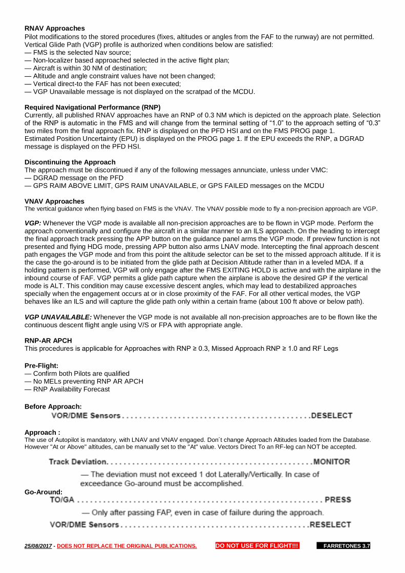
25/08/2017 - DOES NOT REPLACE THE ORIGINAL PUBLICATIONS. DO NOT USE FOR FLIGHT!!! FARRETONES 3.7
RNAV Approaches
Pilot modifications to the stored procedures (fixes, altitudes or angles from the FAF to the runway) are not permitted. Vertical Glide Path (VGP) profile is authorized when conditions below are satisfied: — FMS is the selected Nav source; — Non-localizer based approached selected in the active flight plan; — Aircraft is within 30 NM of destination; — Altitude and angle constraint values have not been changed; — Vertical direct-to the FAF has not been executed; — VGP Unavailable message is not displayed on the scratpad of the MCDU. Required Navigational Performance (RNP) Currently, all published RNAV approaches have an RNP of 0.3 NM which is depicted on the approach plate. Selection of the RNP is automatic in the FMS and will change from the terminal setting of “1.0” to the approach setting of “0.3” two miles from the final approach fix. RNP is displayed on the PFD HSI and on the FMS PROG page 1. Estimated Position Uncertainty (EPU) is displayed on the PROG page 1. If the EPU exceeds the RNP, a DGRAD message is displayed on the PFD HSI. Discontinuing the Approach The approach must be discontinued if any of the following messages annunciate, unless under VMC: — DGRAD message on the PFD — GPS RAIM ABOVE LIMIT, GPS RAIM UNAVAILABLE, or GPS FAILED messages on the MCDU VNAV Approaches The vertical guidance when flying based on FMS is the VNAV. The VNAV possible mode to fly a non-precision approach are VGP.
VGP: Whenever the VGP mode is available all non-precision approaches are to be flown in VGP mode. Perform the approach conventionally and configure the aircraft in a similar manner to an ILS approach. On the heading to intercept the final approach track pressing the APP button on the guidance panel arms the VGP mode. If preview function is not presented and flying HDG mode, pressing APP button also arms LNAV mode. Intercepting the final approach descent path engages the VGP mode and from this point the altitude selector can be set to the missed approach altitude. If it is the case the go-around is to be initiated from the glide path at Decision Altitude rather than in a leveled MDA. If a holding pattern is performed, VGP will only engage after the FMS EXITING HOLD is active and with the airplane in the inbound course of FAF. VGP permits a glide path capture when the airplane is above the desired GP if the vertical mode is ALT. This condition may cause excessive descent angles, which may lead to destabilized approaches specially when the engagement occurs at or in close proximity of the FAF. For all other vertical modes, the VGP behaves like an ILS and will capture the glide path only within a certain frame (about 100 ft above or below path). VGP UNAVAILABLE: Whenever the VGP mode is not available all non-precision approaches are to be flown like the continuous descent flight angle using V/S or FPA with appropriate angle. RNP-AR APCH This procedures is applicable for Approaches with RNP ≥ 0.3, Missed Approach RNP ≥ 1.0 and RF Legs
Pre-Flight: — Confirm both Pilots are qualified — No MELs preventing RNP AR APCH — RNP Availability Forecast
Before Approach:
Approach : The use of Autopilot is mandatory, with LNAV and VNAV engaged. Don´t change Approach Altitudes loaded from the Database. However "At or Above" altitudes, can be manually set to the "At" value. Vectors Direct To an RF-leg can NOT be accepted.
Go-Around:
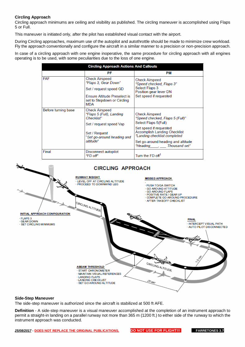
25/08/2017 - DOES NOT REPLACE THE ORIGINAL PUBLICATIONS. DO NOT USE FOR FLIGHT!!! FARRETONES 3.7
Circling Approach
Circling approach minimums are ceiling and visibility as published. The circling maneuver is accomplished using Flaps 5 or Full.
This maneuver is initiated only, after the pilot has established visual contact with the airport.
During Circling approaches, maximum use of the autopilot and autothrottle should be made to minimize crew workload. Fly the approach conventionally and configure the aircraft in a similar manner to a precision or non-precision approach.
In case of a circling approach with one engine inoperative, the same procedure for circling approach with all engines operating is to be used, with some peculiarities due to the loss of one engine.
Side-Step Maneuver
The side-step maneuver is authorized since the aircraft is stabilized at 500 ft AFE.
Definition - A side-step maneuver is a visual maneuver accomplished at the completion of an instrument approach to permit a straight-in landing on a parallel runway not more than 365 m (1200 ft.) to either side of the runway to which the instrument approach was conducted.

25/08/2017 - DOES NOT REPLACE THE ORIGINAL PUBLICATIONS. DO NOT USE FOR FLIGHT!!! FARRETONES 3.7
Visual Approach
To assist in situational awareness, enter the best available approach to the landing runway into the FMS. If an approach is not available, enter the landing runway, then create an intercept leg to the runway with the runway heading as course. -Autopilot and flight director use is at pilot discretion.
Initial Approach - Fly at an altitude of 1500 ft. AFE and enter downwind with Flaps 1 at approximately GD Speed. Select Flaps 2 abeam the approach end of the runway of intended landing at approximately GD Speed. Extend downwind for 30 seconds (+/- 1 sec. for each knot of HW/TW).
Turning Leg - When turning onto base leg, select Flaps 3, extend the landing gear, slow down to GD Speed. If the approach pattern must be extended, delay extending gear and selecting Flaps 3 until approaching the normal visual approach profile. Extend landing Flaps 5 before turning to final.
On Final - Roll out on runway centerline and maintain the appropriate approach speed. Stabilize the aircraft on the selected approach airspeed with a constant rate of descent between 500 fpm and 700 fpm on the desired glide-path (approximately 3°), in-trim. The autopilot must be disengaged no later than 500 ft AGL. Align with the runway approximately 5 miles on final at 1500 ft. AFE or 3 miles on final at 1000 ft. AFE.
Engine-Out Visual Approach: An ILS approach is recommended for any engine-out approach and landing. It provides a stable framework and familiar cues for configuration, deceleration, and descent.
Flap Settings: Preferred landing flap setting is 5.
Setting Minimums: For visual approaches, minimums of 500 ft. AFE will be used for approaches with no instrument back up. When using an instrument approach as a back up, set the appropriate minimums for that approach.
Go-Around Altitude: Flight Crew will set 1500 ft. AFE rounded to the nearest hundred feet.
Prior to the “Landing” Callout All approach callouts will be made in accordance with the procedures outlined in this manual. The PM will callout “Approach lights” or “Runway” unless the PF calls out “Landing.”
Landing Callout For CAT I ILS, Non-Precision, and Visual Approaches The PF may call “Landing” when: — the aircraft is cleared to land; — the aircraft is in position to land safely; — the runway environment will remain in sight until touchdown; and — required visual cues are in sight (as per the MGO).
1. If approach lights are not in sight at “Minimums”, the PM will callout “No Contact”. The PF will then callout “Go-Around Flaps” and initiate the go-around. 2. “Continuing” indicates the PF's intention to fly below minimums, during an ILS, or procedures with an MDA, with the approach lights in sight, but no lower than 100 ft. below DA/MDA, while attempting to acquire the required visual cues for landing.
After the “Landing” Callout The PM will continue to monitor instruments and call out any deviations that would prevent a safe landing. No further callouts are required.
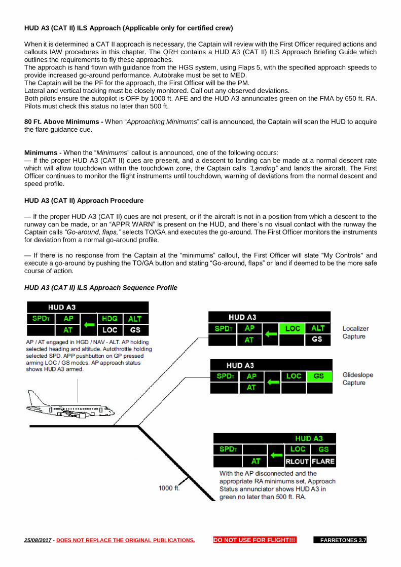
25/08/2017 - DOES NOT REPLACE THE ORIGINAL PUBLICATIONS. DO NOT USE FOR FLIGHT!!! FARRETONES 3.7
HUD A3 (CAT II) ILS Approach (Applicable only for certified crew)
When it is determined a CAT II approach is necessary, the Captain will review with the First Officer required actions and callouts IAW procedures in this chapter. The QRH contains a HUD A3 (CAT II) ILS Approach Briefing Guide which outlines the requirements to fly these approaches. The approach is hand flown with guidance from the HGS system, using Flaps 5, with the specified approach speeds to provide increased go-around performance. Autobrake must be set to MED. The Captain will be the PF for the approach, the First Officer will be the PM. Lateral and vertical tracking must be closely monitored. Call out any observed deviations. Both pilots ensure the autopilot is OFF by 1000 ft. AFE and the HUD A3 annunciates green on the FMA by 650 ft. RA. Pilots must check this status no later than 500 ft. 80 Ft. Above Minimums - When “Approaching Minimums” call is announced, the Captain will scan the HUD to acquire the flare guidance cue. Minimums - When the “Minimums” callout is announced, one of the following occurs: — If the proper HUD A3 (CAT II) cues are present, and a descent to landing can be made at a normal descent rate which will allow touchdown within the touchdown zone, the Captain calls “Landing” and lands the aircraft. The First Officer continues to monitor the flight instruments until touchdown, warning of deviations from the normal descent and speed profile.
HUD A3 (CAT II) Approach Procedure
— If the proper HUD A3 (CAT II) cues are not present, or if the aircraft is not in a position from which a descent to the runway can be made, or an “APPR WARN” is present on the HUD, and there´s no visual contact with the runway the Captain calls “Go-around, flaps,” selects TO/GA and executes the go-around. The First Officer monitors the instruments for deviation from a normal go-around profile. — If there is no response from the Captain at the “minimums” callout, the First Officer will state "My Controls" and execute a go-around by pushing the TO/GA button and stating “Go-around, flaps” or land if deemed to be the more safe course of action.
HUD A3 (CAT II) ILS Approach Sequence Profile
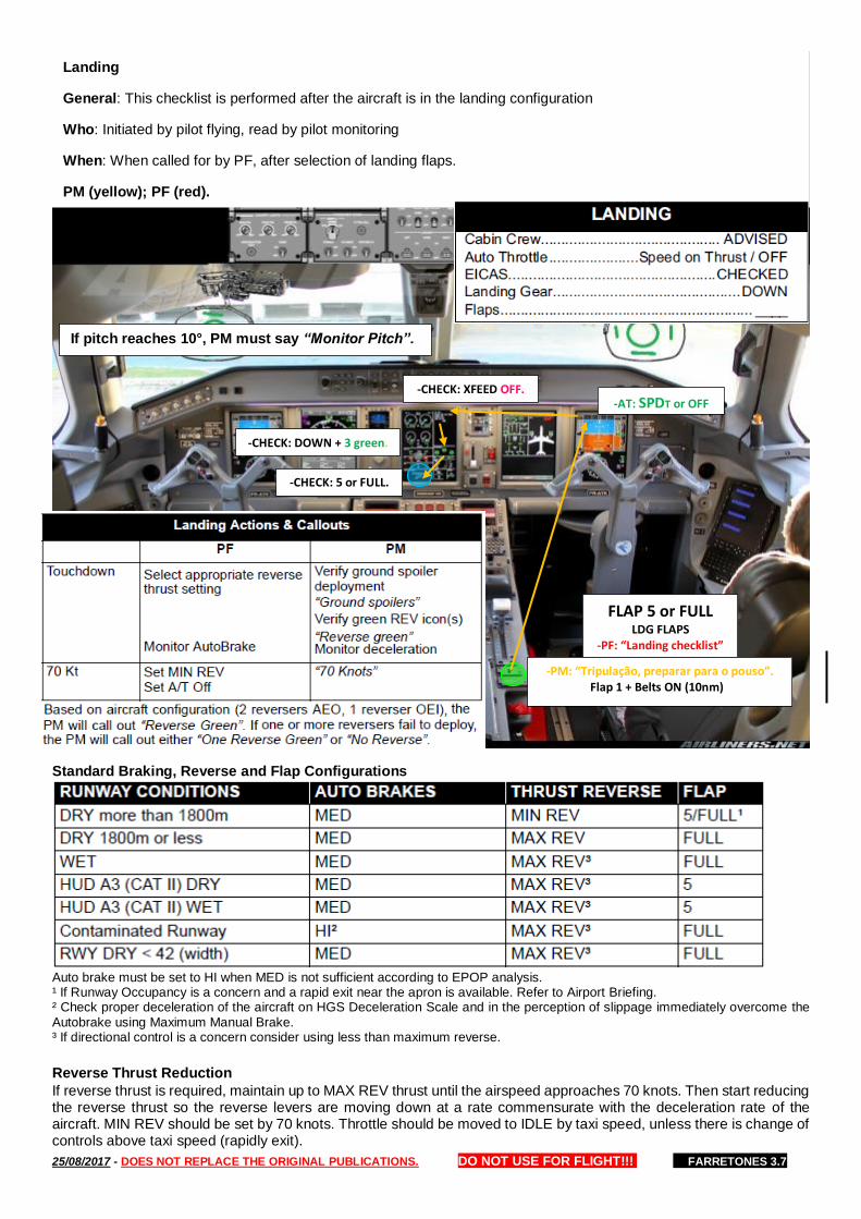
25/08/2017 - DOES NOT REPLACE THE ORIGINAL PUBLICATIONS. DO NOT USE FOR FLIGHT!!! FARRETONES 3.7
Standard Braking, Reverse and Flap Configurations
Auto brake must be set to HI when MED is not sufficient according to EPOP analysis. ¹ If Runway Occupancy is a concern and a rapid exit near the apron is available. Refer to Airport Briefing. ² Check proper deceleration of the aircraft on HGS Deceleration Scale and in the perception of slippage immediately overcome the Autobrake using Maximum Manual Brake. ³ If directional control is a concern consider using less than maximum reverse.
Reverse Thrust Reduction
If reverse thrust is required, maintain up to MAX REV thrust until the airspeed approaches 70 knots. Then start reducing the reverse thrust so the reverse levers are moving down at a rate commensurate with the deceleration rate of the aircraft. MIN REV should be set by 70 knots. Throttle should be moved to IDLE by taxi speed, unless there is change of controls above taxi speed (rapidly exit).
-PM: “Tripulação, preparar para o pouso”. Flap 1 + Belts ON (10nm)
-CHECK: 5 or FULL.
-CHECK: DOWN + 3 green.
-CHECK: XFEED OFF.
FLAP 5 or FULL LDG FLAPS
-PF: “Landing checklist”
-AT: SPDT or OFF
Landing
General: This checklist is performed after the aircraft is in the landing configuration
Who: Initiated by pilot flying, read by pilot monitoring
When: When called for by PF, after selection of landing flaps.
PM (yellow); PF (red).
If pitch reaches 10°, PM must say “Monitor Pitch”.
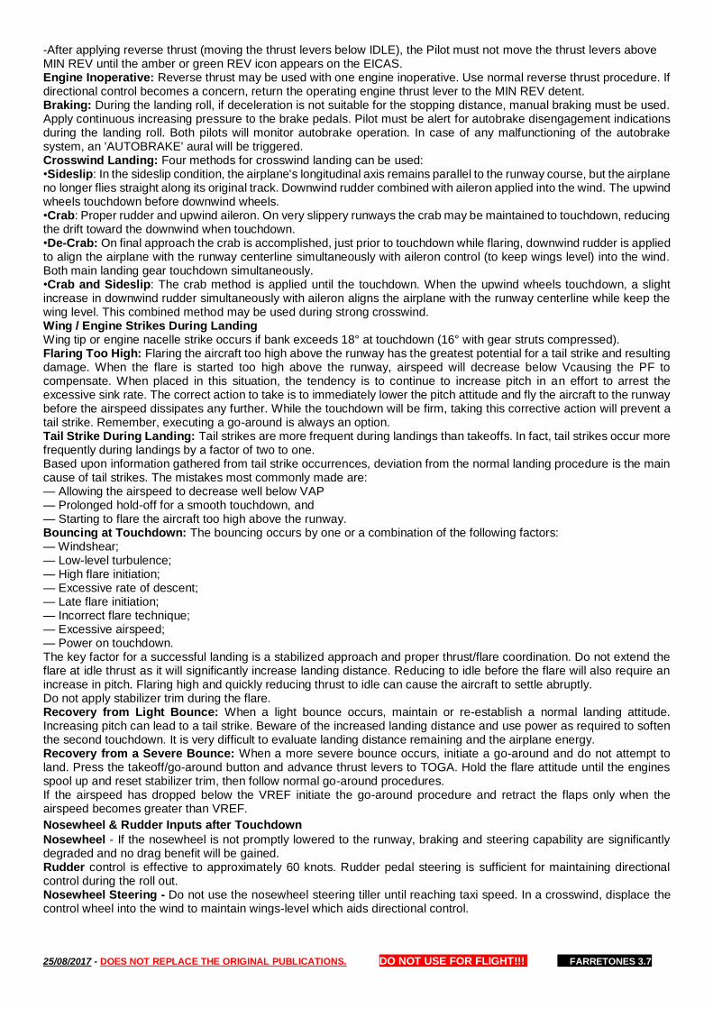
25/08/2017 - DOES NOT REPLACE THE ORIGINAL PUBLICATIONS. DO NOT USE FOR FLIGHT!!! FARRETONES 3.7
-After applying reverse thrust (moving the thrust levers below IDLE), the Pilot must not move the thrust levers above MIN REV until the amber or green REV icon appears on the EICAS. Engine Inoperative: Reverse thrust may be used with one engine inoperative. Use normal reverse thrust procedure. If directional control becomes a concern, return the operating engine thrust lever to the MIN REV detent. Braking: During the landing roll, if deceleration is not suitable for the stopping distance, manual braking must be used. Apply continuous increasing pressure to the brake pedals. Pilot must be alert for autobrake disengagement indications during the landing roll. Both pilots will monitor autobrake operation. In case of any malfunctioning of the autobrake system, an 'AUTOBRAKE' aural will be triggered. Crosswind Landing: Four methods for crosswind landing can be used: •Sideslip: In the sideslip condition, the airplane's longitudinal axis remains parallel to the runway course, but the airplane no longer flies straight along its original track. Downwind rudder combined with aileron applied into the wind. The upwind wheels touchdown before downwind wheels. •Crab: Proper rudder and upwind aileron. On very slippery runways the crab may be maintained to touchdown, reducing the drift toward the downwind when touchdown. •De-Crab: On final approach the crab is accomplished, just prior to touchdown while flaring, downwind rudder is applied to align the airplane with the runway centerline simultaneously with aileron control (to keep wings level) into the wind. Both main landing gear touchdown simultaneously. •Crab and Sideslip: The crab method is applied until the touchdown. When the upwind wheels touchdown, a slight increase in downwind rudder simultaneously with aileron aligns the airplane with the runway centerline while keep the wing level. This combined method may be used during strong crosswind. Wing / Engine Strikes During Landing Wing tip or engine nacelle strike occurs if bank exceeds 18° at touchdown (16° with gear struts compressed). Flaring Too High: Flaring the aircraft too high above the runway has the greatest potential for a tail strike and resulting damage. When the flare is started too high above the runway, airspeed will decrease below Vcausing the PF to compensate. When placed in this situation, the tendency is to continue to increase pitch in an effort to arrest the excessive sink rate. The correct action to take is to immediately lower the pitch attitude and fly the aircraft to the runway before the airspeed dissipates any further. While the touchdown will be firm, taking this corrective action will prevent a tail strike. Remember, executing a go-around is always an option. Tail Strike During Landing: Tail strikes are more frequent during landings than takeoffs. In fact, tail strikes occur more frequently during landings by a factor of two to one. Based upon information gathered from tail strike occurrences, deviation from the normal landing procedure is the main cause of tail strikes. The mistakes most commonly made are: — Allowing the airspeed to decrease well below VAP — Prolonged hold-off for a smooth touchdown, and — Starting to flare the aircraft too high above the runway. Bouncing at Touchdown: The bouncing occurs by one or a combination of the following factors: — Windshear; — Low-level turbulence; — High flare initiation; — Excessive rate of descent; — Late flare initiation; — Incorrect flare technique; — Excessive airspeed; — Power on touchdown. The key factor for a successful landing is a stabilized approach and proper thrust/flare coordination. Do not extend the flare at idle thrust as it will significantly increase landing distance. Reducing to idle before the flare will also require an increase in pitch. Flaring high and quickly reducing thrust to idle can cause the aircraft to settle abruptly. Do not apply stabilizer trim during the flare. Recovery from Light Bounce: When a light bounce occurs, maintain or re-establish a normal landing attitude. Increasing pitch can lead to a tail strike. Beware of the increased landing distance and use power as required to soften the second touchdown. It is very difficult to evaluate landing distance remaining and the airplane energy. Recovery from a Severe Bounce: When a more severe bounce occurs, initiate a go-around and do not attempt to land. Press the takeoff/go-around button and advance thrust levers to TOGA. Hold the flare attitude until the engines spool up and reset stabilizer trim, then follow normal go-around procedures. If the airspeed has dropped below the VREF initiate the go-around procedure and retract the flaps only when the airspeed becomes greater than VREF.
Nosewheel & Rudder Inputs after Touchdown
Nosewheel - If the nosewheel is not promptly lowered to the runway, braking and steering capability are significantly degraded and no drag benefit will be gained. Rudder control is effective to approximately 60 knots. Rudder pedal steering is sufficient for maintaining directional control during the roll out. Nosewheel Steering - Do not use the nosewheel steering tiller until reaching taxi speed. In a crosswind, displace the control wheel into the wind to maintain wings-level which aids directional control.
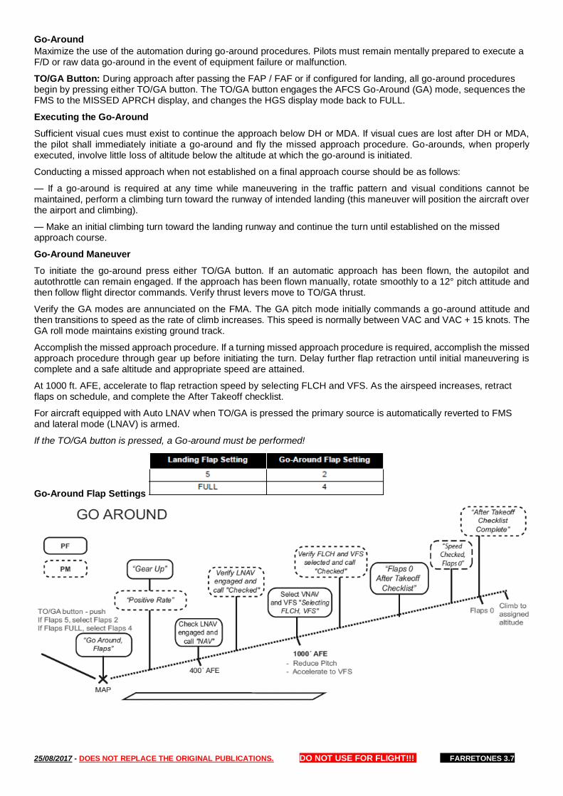
25/08/2017 - DOES NOT REPLACE THE ORIGINAL PUBLICATIONS. DO NOT USE FOR FLIGHT!!! FARRETONES 3.7
Go-Around
Maximize the use of the automation during go-around procedures. Pilots must remain mentally prepared to execute a F/D or raw data go-around in the event of equipment failure or malfunction.
TO/GA Button: During approach after passing the FAP / FAF or if configured for landing, all go-around procedures begin by pressing either TO/GA button. The TO/GA button engages the AFCS Go-Around (GA) mode, sequences the FMS to the MISSED APRCH display, and changes the HGS display mode back to FULL.
Executing the Go-Around
Sufficient visual cues must exist to continue the approach below DH or MDA. If visual cues are lost after DH or MDA, the pilot shall immediately initiate a go-around and fly the missed approach procedure. Go-arounds, when properly executed, involve little loss of altitude below the altitude at which the go-around is initiated.
Conducting a missed approach when not established on a final approach course should be as follows:
— If a go-around is required at any time while maneuvering in the traffic pattern and visual conditions cannot be maintained, perform a climbing turn toward the runway of intended landing (this maneuver will position the aircraft over the airport and climbing).
— Make an initial climbing turn toward the landing runway and continue the turn until established on the missed approach course.
Go-Around Maneuver
To initiate the go-around press either TO/GA button. If an automatic approach has been flown, the autopilot and autothrottle can remain engaged. If the approach has been flown manually, rotate smoothly to a 12° pitch attitude and then follow flight director commands. Verify thrust levers move to TO/GA thrust.
Verify the GA modes are annunciated on the FMA. The GA pitch mode initially commands a go-around attitude and then transitions to speed as the rate of climb increases. This speed is normally between VAC and VAC + 15 knots. The GA roll mode maintains existing ground track.
Accomplish the missed approach procedure. If a turning missed approach procedure is required, accomplish the missed approach procedure through gear up before initiating the turn. Delay further flap retraction until initial maneuvering is complete and a safe altitude and appropriate speed are attained.
At 1000 ft. AFE, accelerate to flap retraction speed by selecting FLCH and VFS. As the airspeed increases, retract flaps on schedule, and complete the After Takeoff checklist.
For aircraft equipped with Auto LNAV when TO/GA is pressed the primary source is automatically reverted to FMS and lateral mode (LNAV) is armed.
If the TO/GA button is pressed, a Go-around must be performed!
Go-Around Flap Settings
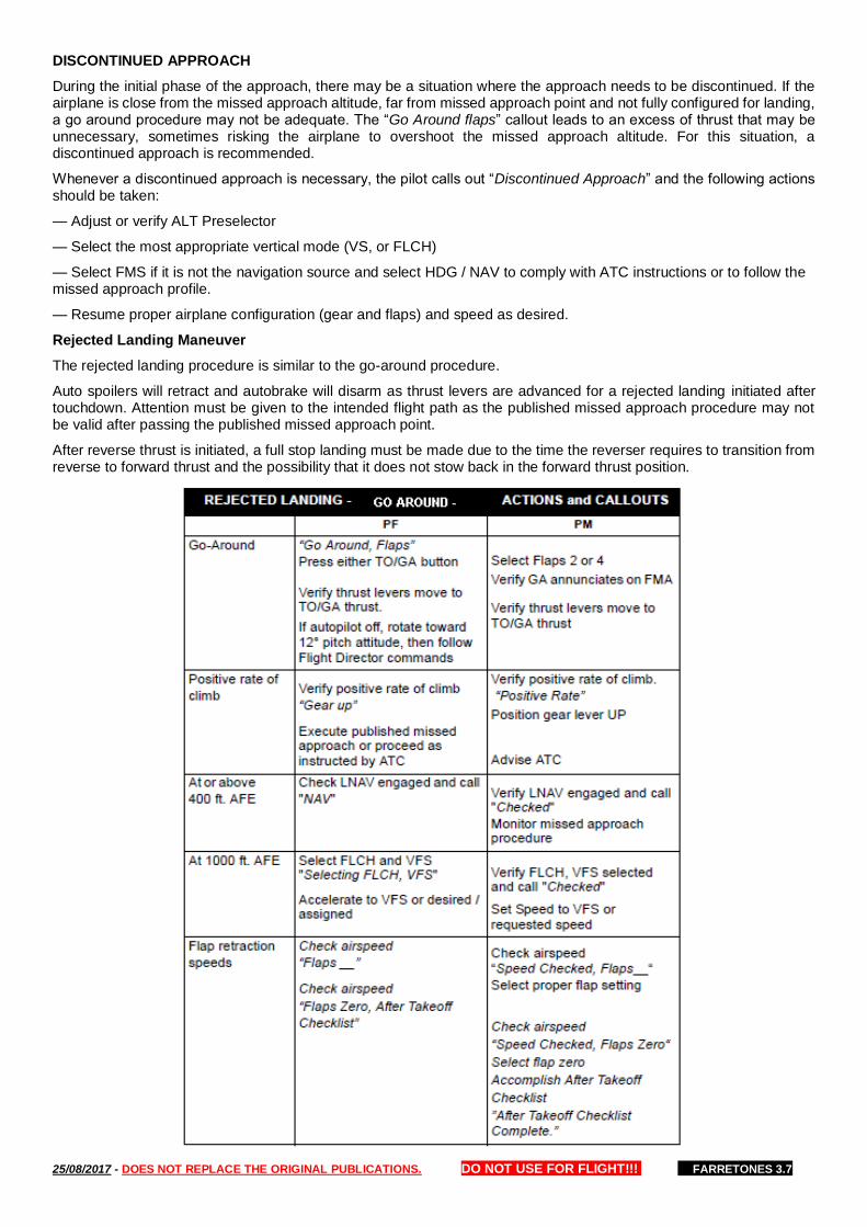
25/08/2017 - DOES NOT REPLACE THE ORIGINAL PUBLICATIONS. DO NOT USE FOR FLIGHT!!! FARRETONES 3.7
DISCONTINUED APPROACH
During the initial phase of the approach, there may be a situation where the approach needs to be discontinued. If the airplane is close from the missed approach altitude, far from missed approach point and not fully configured for landing, a go around procedure may not be adequate. The “Go Around flaps” callout leads to an excess of thrust that may be unnecessary, sometimes risking the airplane to overshoot the missed approach altitude. For this situation, a discontinued approach is recommended.
Whenever a discontinued approach is necessary, the pilot calls out “Discontinued Approach” and the following actions should be taken:
— Adjust or verify ALT Preselector
— Select the most appropriate vertical mode (VS, or FLCH)
— Select FMS if it is not the navigation source and select HDG / NAV to comply with ATC instructions or to follow the missed approach profile.
— Resume proper airplane configuration (gear and flaps) and speed as desired.
Rejected Landing Maneuver
The rejected landing procedure is similar to the go-around procedure.
Auto spoilers will retract and autobrake will disarm as thrust levers are advanced for a rejected landing initiated after touchdown. Attention must be given to the intended flight path as the published missed approach procedure may not be valid after passing the published missed approach point.
After reverse thrust is initiated, a full stop landing must be made due to the time the reverser requires to transition from reverse to forward thrust and the possibility that it does not stow back in the forward thrust position.
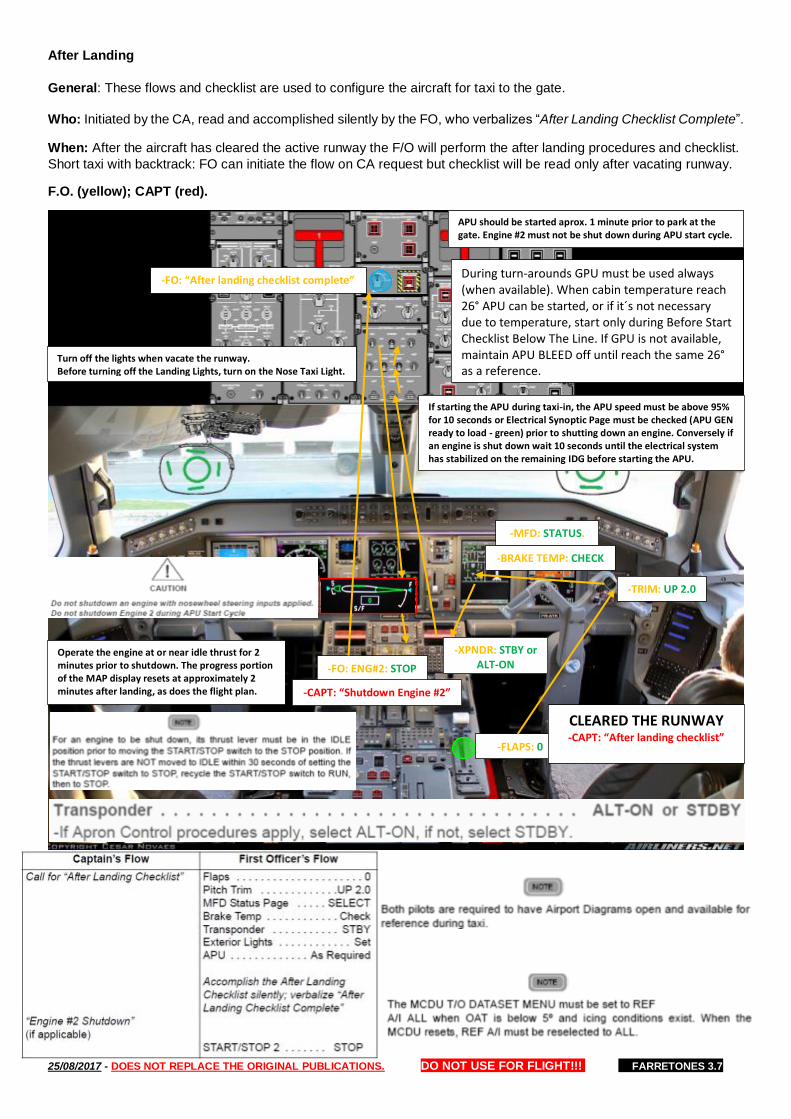
25/08/2017 - DOES NOT REPLACE THE ORIGINAL PUBLICATIONS. DO NOT USE FOR FLIGHT!!! FARRETONES 3.7
After Landing
General: These flows and checklist are used to configure the aircraft for taxi to the gate.
Who: Initiated by the CA, read and accomplished silently by the FO, who verbalizes “After Landing Checklist Complete”.
When: After the aircraft has cleared the active runway the F/O will perform the after landing procedures and checklist.
Short taxi with backtrack: FO can initiate the flow on CA request but checklist will be read only after vacating runway.
F.O. (yellow); CAPT (red).
-FLAPS: 0
CLEARED THE RUNWAY -CAPT: “After landing checklist”
-MFD: STATUS.
-XPNDR: STBY or ALT-ON
-TRIM: UP 2.0
-BRAKE TEMP: CHECK
Turn off the lights when vacate the runway. Before turning off the Landing Lights, turn on the Nose Taxi Light.
APU should be started aprox. 1 minute prior to park at the gate. Engine #2 must not be shut down during APU start cycle.
During turn-arounds GPU must be used always (when available). When cabin temperature reach 26° APU can be started, or if it´s not necessary due to temperature, start only during Before Start Checklist Below The Line. If GPU is not available, maintain APU BLEED off until reach the same 26° as a reference.
Operate the engine at or near idle thrust for 2 minutes prior to shutdown. The progress portion of the MAP display resets at approximately 2 minutes after landing, as does the flight plan.
-FO: ENG#2: STOP
If starting the APU during taxi-in, the APU speed must be above 95% for 10 seconds or Electrical Synoptic Page must be checked (APU GEN ready to load - green) prior to shutting down an engine. Conversely if an engine is shut down wait 10 seconds until the electrical system has stabilized on the remaining IDG before starting the APU.
-FO: “After landing checklist complete”
-CAPT: “Shutdown Engine #2”
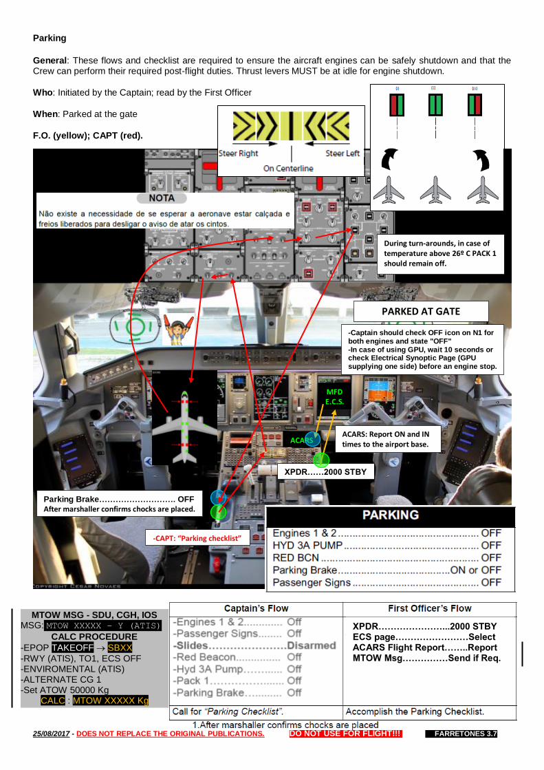
25/08/2017 - DOES NOT REPLACE THE ORIGINAL PUBLICATIONS. DO NOT USE FOR FLIGHT!!! FARRETONES 3.7
Parking
General: These flows and checklist are required to ensure the aircraft engines can be safely shutdown and that the Crew can perform their required post-flight duties. Thrust levers MUST be at idle for engine shutdown.
Who: Initiated by the Captain; read by the First Officer
When: Parked at the gate
F.O. (yellow); CAPT (red).
PARKED AT GATE
-CAPT: “Parking checklist”
During turn-arounds, in case of temperature above 26º C PACK 1 should remain off.
-Captain should check OFF icon on N1 for both engines and state "OFF" -In case of using GPU, wait 10 seconds or check Electrical Synoptic Page (GPU supplying one side) before an engine stop.
Parking Brake………………………. OFF After marshaller confirms chocks are placed.
MFD E.C.S.
ACARS ACARS: Report ON and IN times to the airport base.
XPDR……2000 STBY
XPDR…………………...2000 STBY ECS page……………………Select ACARS Flight Report……..Report MTOW Msg……………Send if Req.
MTOW MSG - SDU, CGH, IOS MSG: MTOW XXXXX – Y (ATIS)
CALC PROCEDURE
-EPOP TAKEOFF SBXX
-RWY (ATIS), TO1, ECS OFF -ENVIROMENTAL (ATIS) -ALTERNATE CG 1 -Set ATOW 50000 Kg
CALC : MTOW XXXXX Kg
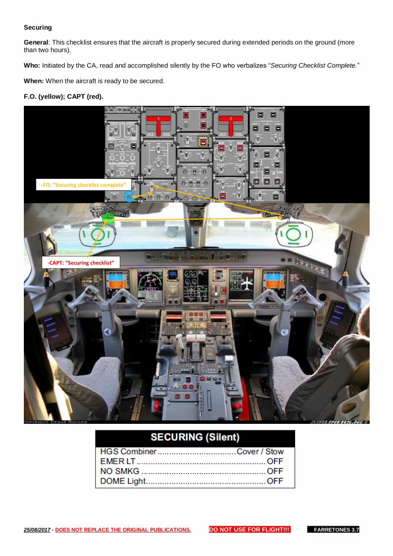
25/08/2017 - DOES NOT REPLACE THE ORIGINAL PUBLICATIONS. DO NOT USE FOR FLIGHT!!! FARRETONES 3.7
Securing
General: This checklist ensures that the aircraft is properly secured during extended periods on the ground (more than two hours).
Who: Initiated by the CA, read and accomplished silently by the FO who verbalizes “Securing Checklist Complete.”
When: When the aircraft is ready to be secured.
F.O. (yellow); CAPT (red).
-CAPT: “Securing checklist”
-FO: “Securing checklist complete”
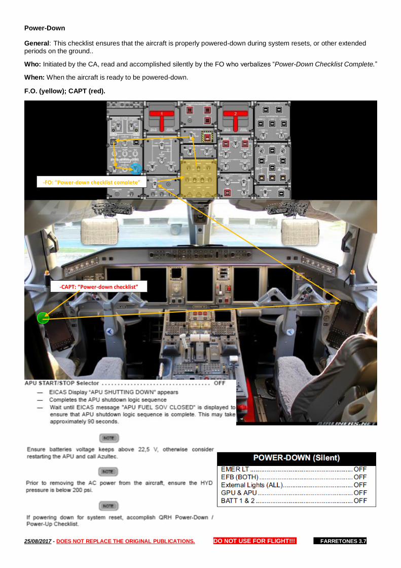
25/08/2017 - DOES NOT REPLACE THE ORIGINAL PUBLICATIONS. DO NOT USE FOR FLIGHT!!! FARRETONES 3.7
Power-Down
General: This checklist ensures that the aircraft is properly powered-down during system resets, or other extended periods on the ground..
Who: Initiated by the CA, read and accomplished silently by the FO who verbalizes “Power-Down Checklist Complete.”
When: When the aircraft is ready to be powered-down.
F.O. (yellow); CAPT (red).
-CAPT: “Power-down checklist”
-FO: “Power-down checklist complete”
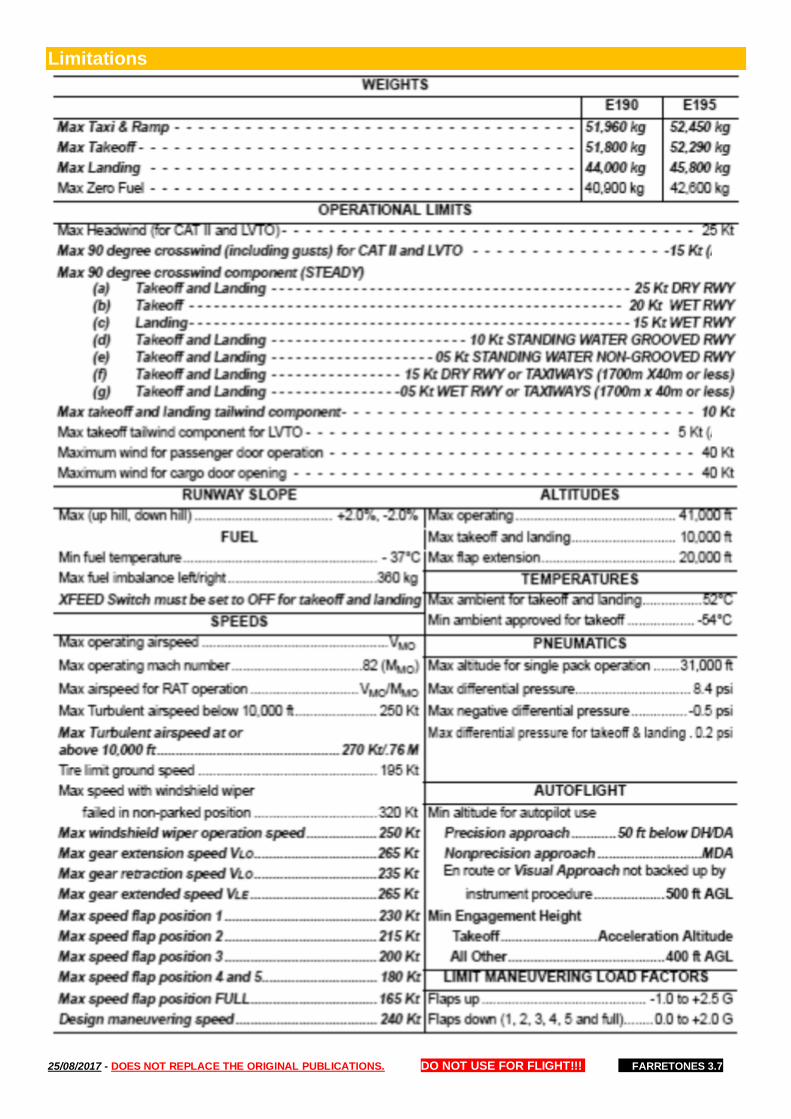
25/08/2017 - DOES NOT REPLACE THE ORIGINAL PUBLICATIONS. DO NOT USE FOR FLIGHT!!! FARRETONES 3.7
Limitations

25/08/2017 - DOES NOT REPLACE THE ORIGINAL PUBLICATIONS. DO NOT USE FOR FLIGHT!!! FARRETONES 3.7
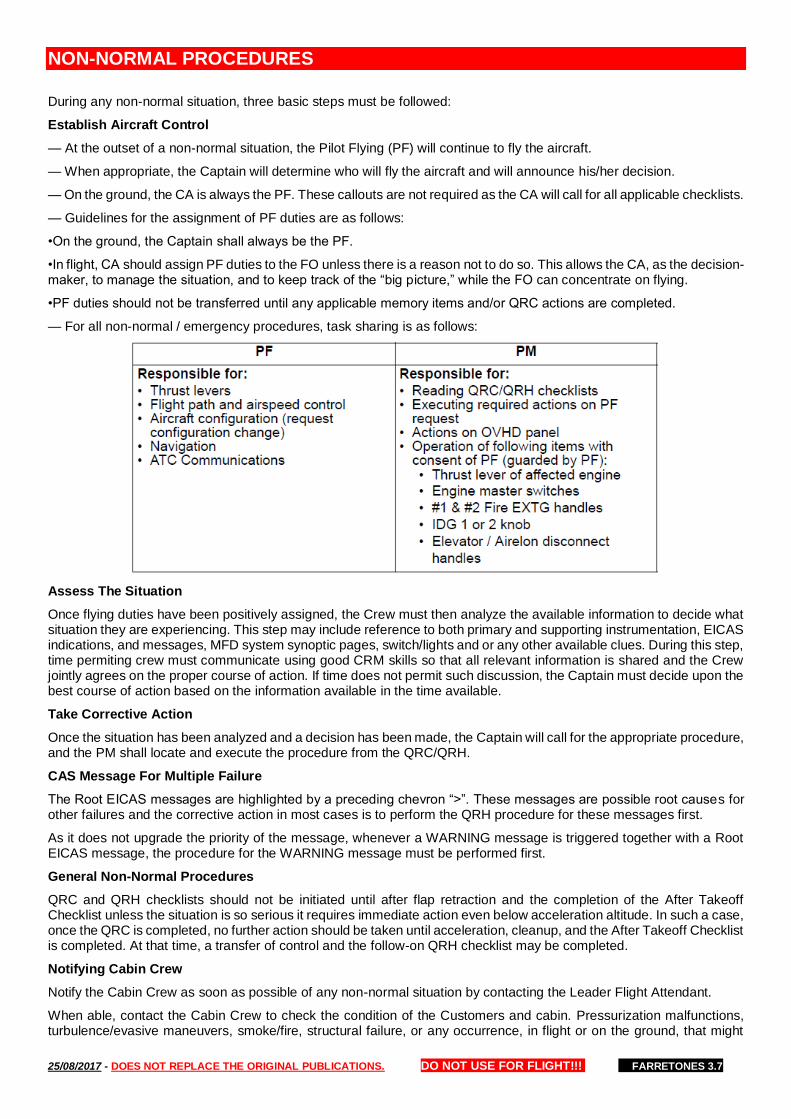
25/08/2017 - DOES NOT REPLACE THE ORIGINAL PUBLICATIONS. DO NOT USE FOR FLIGHT!!! FARRETONES 3.7
NON-NORMAL PROCEDURES
During any non-normal situation, three basic steps must be followed:
Establish Aircraft Control
— At the outset of a non-normal situation, the Pilot Flying (PF) will continue to fly the aircraft.
— When appropriate, the Captain will determine who will fly the aircraft and will announce his/her decision.
— On the ground, the CA is always the PF. These callouts are not required as the CA will call for all applicable checklists.
— Guidelines for the assignment of PF duties are as follows:
•On the ground, the Captain shall always be the PF.
•In flight, CA should assign PF duties to the FO unless there is a reason not to do so. This allows the CA, as the decision-maker, to manage the situation, and to keep track of the “big picture,” while the FO can concentrate on flying.
•PF duties should not be transferred until any applicable memory items and/or QRC actions are completed.
— For all non-normal / emergency procedures, task sharing is as follows:
Assess The Situation
Once flying duties have been positively assigned, the Crew must then analyze the available information to decide what situation they are experiencing. This step may include reference to both primary and supporting instrumentation, EICAS indications, and messages, MFD system synoptic pages, switch/lights and or any other available clues. During this step, time permiting crew must communicate using good CRM skills so that all relevant information is shared and the Crew jointly agrees on the proper course of action. If time does not permit such discussion, the Captain must decide upon the best course of action based on the information available in the time available.
Take Corrective Action
Once the situation has been analyzed and a decision has been made, the Captain will call for the appropriate procedure, and the PM shall locate and execute the procedure from the QRC/QRH.
CAS Message For Multiple Failure
The Root EICAS messages are highlighted by a preceding chevron “>”. These messages are possible root causes for other failures and the corrective action in most cases is to perform the QRH procedure for these messages first.
As it does not upgrade the priority of the message, whenever a WARNING message is triggered together with a Root EICAS message, the procedure for the WARNING message must be performed first.
General Non-Normal Procedures
QRC and QRH checklists should not be initiated until after flap retraction and the completion of the After Takeoff Checklist unless the situation is so serious it requires immediate action even below acceleration altitude. In such a case, once the QRC is completed, no further action should be taken until acceleration, cleanup, and the After Takeoff Checklist is completed. At that time, a transfer of control and the follow-on QRH checklist may be completed.
Notifying Cabin Crew
Notify the Cabin Crew as soon as possible of any non-normal situation by contacting the Leader Flight Attendant.
When able, contact the Cabin Crew to check the condition of the Customers and cabin. Pressurization malfunctions, turbulence/evasive maneuvers, smoke/fire, structural failure, or any occurrence, in flight or on the ground, that might
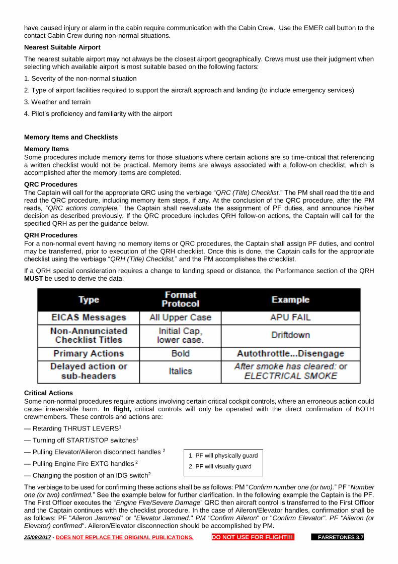
25/08/2017 - DOES NOT REPLACE THE ORIGINAL PUBLICATIONS. DO NOT USE FOR FLIGHT!!! FARRETONES 3.7
have caused injury or alarm in the cabin require communication with the Cabin Crew. Use the EMER call button to the contact Cabin Crew during non-normal situations.
Nearest Suitable Airport
The nearest suitable airport may not always be the closest airport geographically. Crews must use their judgment when selecting which available airport is most suitable based on the following factors:
1. Severity of the non-normal situation
2. Type of airport facilities required to support the aircraft approach and landing (to include emergency services)
3. Weather and terrain
4. Pilot’s proficiency and familiarity with the airport
Memory Items and Checklists
Memory Items
Some procedures include memory items for those situations where certain actions are so time-critical that referencing a written checklist would not be practical. Memory items are always associated with a follow-on checklist, which is accomplished after the memory items are completed.
QRC Procedures
The Captain will call for the appropriate QRC using the verbiage “QRC (Title) Checklist.” The PM shall read the title and read the QRC procedure, including memory item steps, if any. At the conclusion of the QRC procedure, after the PM reads, “QRC actions complete,” the Captain shall reevaluate the assignment of PF duties, and announce his/her decision as described previously. If the QRC procedure includes QRH follow-on actions, the Captain will call for the specified QRH as per the guidance below.
QRH Procedures
For a non-normal event having no memory items or QRC procedures, the Captain shall assign PF duties, and control may be transferred, prior to execution of the QRH checklist. Once this is done, the Captain calls for the appropriate checklist using the verbiage “QRH (Title) Checklist,” and the PM accomplishes the checklist.
If a QRH special consideration requires a change to landing speed or distance, the Performance section of the QRH MUST be used to derive the data.
Critical Actions
Some non-normal procedures require actions involving certain critical cockpit controls, where an erroneous action could cause irreversible harm. In flight, critical controls will only be operated with the direct confirmation of BOTH crewmembers. These controls and actions are:
— Retarding THRUST LEVERS1
— Turning off START/STOP switches1
— Pulling Elevator/Aileron disconnect handles 2
— Pulling Engine Fire EXTG handles 2
— Changing the position of an IDG switch2
The verbiage to be used for confirming these actions shall be as follows: PM “Confirm number one (or two).” PF “Number one (or two) confirmed.” See the example below for further clarification. In the following example the Captain is the PF. The First Officer executes the “Engine Fire/Severe Damage” QRC then aircraft control is transferred to the First Officer and the Captain continues with the checklist procedure. In the case of Aileron/Elevator handles, confirmation shall be as follows: PF "Aileron Jammed" or "Elevator Jammed." PM "Confirm Aileron" or "Confirm Elevator". PF "Aileron (or Elevator) confirmed". Aileron/Elevator disconnection should be accomplished by PM.
1. PF will physically guard
2. PF will visually guard

25/08/2017 - DOES NOT REPLACE THE ORIGINAL PUBLICATIONS. DO NOT USE FOR FLIGHT!!! FARRETONES 3.7
Interrupting a Checklist
Do not skip items. If it becomes necessary to interrupt a procedure at any time, for a timely configuration change for example, the flying pilot will state, “Stop checklist.” After the configuration change is accomplished, the pilot flying will state, “Continue checklist.” The reading of the checklist should resume by reading the last completed item before the interruption occurred. If for any reason there is any doubt as to the last completed item, the entire checklist will be re-accomplished from the beginning.
— If an item is inoperative due to an MEL, the response will be, “INOP.”
— If an item is not applicable on a particular flight the response will be, “NOT REQUIRED.”
— After completion of checklists, the pilot reading the checklist will say”________ checklist complete.”
Emergency Cockpit / Cabin Signal
In the event of an emergency, the Flight Crew will notify the cabin by pressing the emergency call button, via the all call, or via the interphone. This signals an emergency that requires immediate communication with the Cabin Crew. The Leader Flight Attendant will immediately contact the Captain for instructions and, if directed, may be required to proceed to the Flight Deck for instructions.
The briefing for the Leader Flight Attendant should include information regarding the emergency, in a format using the acronym, T.E.S.T.
T Type of Emergency (i.e. ditching, gear-up landing, hydraulic failure, etc.)
E Evacuation; A statement of whether or not preparation for an evacuation is required or likely to be needed.
S Signal; Define the signals to be used during the emergency (i.e. Brace for Impact). Review the use of the “Echo Victor” sequence and the aircraft’s evacuation signal equipment.
T Time; The amount of time remaining until the landing, ditching or evacuation.
Captain should ask for acknowledge from Cabin Crew.
Circuit Breaker
A tripped circuit breaker is usually a result of an abnormality in the electrical load or in associated wiring.
Circuit breakers must not be reset in-flight, unless the checklist specifically directs to do so or if it is imperative for the safe completion of the flight.
Careful consideration must be given to the timing and duration of the reset. Should the circuit breaker trip again, no further attempt should be made to reset that circuit breaker.

25/08/2017 - DOES NOT REPLACE THE ORIGINAL PUBLICATIONS. DO NOT USE FOR FLIGHT!!! FARRETONES 3.7
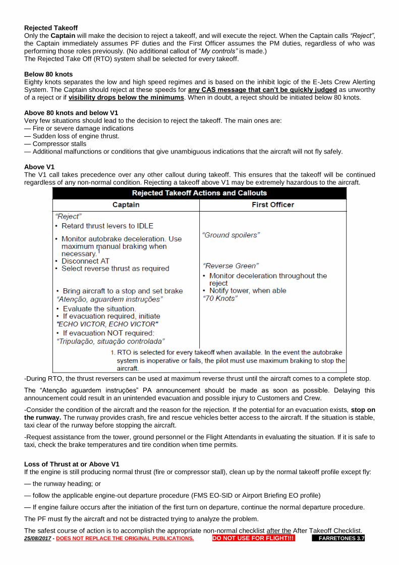
25/08/2017 - DOES NOT REPLACE THE ORIGINAL PUBLICATIONS. DO NOT USE FOR FLIGHT!!! FARRETONES 3.7
Rejected Takeoff Only the Captain will make the decision to reject a takeoff, and will execute the reject. When the Captain calls “Reject”, the Captain immediately assumes PF duties and the First Officer assumes the PM duties, regardless of who was performing those roles previously. (No additional callout of “My controls” is made.) The Rejected Take Off (RTO) system shall be selected for every takeoff. Below 80 knots Eighty knots separates the low and high speed regimes and is based on the inhibit logic of the E-Jets Crew Alerting System. The Captain should reject at these speeds for any CAS message that can’t be quickly judged as unworthy of a reject or if visibility drops below the minimums. When in doubt, a reject should be initiated below 80 knots. Above 80 knots and below V1 Very few situations should lead to the decision to reject the takeoff. The main ones are: — Fire or severe damage indications — Sudden loss of engine thrust. — Compressor stalls — Additional malfunctions or conditions that give unambiguous indications that the aircraft will not fly safely. Above V1 The V1 call takes precedence over any other callout during takeoff. This ensures that the takeoff will be continued regardless of any non-normal condition. Rejecting a takeoff above V1 may be extremely hazardous to the aircraft.
-During RTO, the thrust reversers can be used at maximum reverse thrust until the aircraft comes to a complete stop.
The “Atenção aguardem instruções” PA announcement should be made as soon as possible. Delaying this announcement could result in an unintended evacuation and possible injury to Customers and Crew.
-Consider the condition of the aircraft and the reason for the rejection. If the potential for an evacuation exists, stop on the runway. The runway provides crash, fire and rescue vehicles better access to the aircraft. If the situation is stable, taxi clear of the runway before stopping the aircraft.
-Request assistance from the tower, ground personnel or the Flight Attendants in evaluating the situation. If it is safe to taxi, check the brake temperatures and tire condition when time permits.
Loss of Thrust at or Above V1 If the engine is still producing normal thrust (fire or compressor stall), clean up by the normal takeoff profile except fly:
— the runway heading; or
— follow the applicable engine-out departure procedure (FMS EO-SID or Airport Briefing EO profile)
— If engine failure occurs after the initiation of the first turn on departure, continue the normal departure procedure.
The PF must fly the aircraft and not be distracted trying to analyze the problem.
The safest course of action is to accomplish the appropriate non-normal checklist after the After Takeoff Checklist.

25/08/2017 - DOES NOT REPLACE THE ORIGINAL PUBLICATIONS. DO NOT USE FOR FLIGHT!!! FARRETONES 3.7
Under compelling circumstances such as severe vibration, reverse deployed adverse flight characteristics, it may be necessary to accomplish the QRC items even below acceleration altitude.
The lateral mode MUST be Heading (HDG) when conducting a takeoff with a loss of thrust at or above V1 until reaching V2+10kt. VNAV mode must not be armed below acceleration altitude. After reaching V2+10 and flying in a EO-SID or normal SID NAV mode can be activated.
Fuel XFEED: Use of the fuel crossfeed selector (XFEED) will be confirmed by both pilots.
Engine Failure or Fire Recognition / Callout: The first pilot recognizing the engine failure or fire will make the callout “Engine Failure” or “Engine Fire” but will not identify the engine.
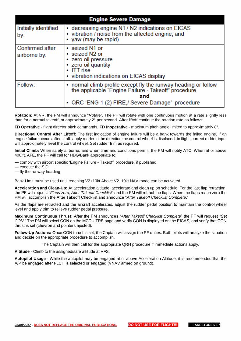
25/08/2017 - DOES NOT REPLACE THE ORIGINAL PUBLICATIONS. DO NOT USE FOR FLIGHT!!! FARRETONES 3.7
Rotation: At VR, the PM will announce “Rotate”. The PF will rotate with one continuous motion at a rate slightly less than for a normal takeoff, or approximately 2° per second. After liftoff continue the rotation rate as follows:
FD Operative - flight director pitch commands. FD Inoperative - maximum pitch angle limited to approximately 8°.
Directional Control After Liftoff: The first indication of engine failure will be a bank towards the failed engine. If an engine failure occurs after liftoff, apply rudder in the direction the control wheel is displaced. In flight, correct rudder input will approximately level the control wheel. Set rudder trim as required.
Initial Climb: When safely airborne, and when time and conditions permit, the PM will notify ATC. When at or above 400 ft. AFE, the PF will call for HDG/Bank appropriate to:
— comply with airport specific ‘Engine Failure - Takeoff’ procedure, if published — execute the SID — fly the runway heading Bank Limit must be used until reaching V2+10kt.Above V2+10kt NAV mode can be activated.
Acceleration and Clean-Up: At acceleration altitude, accelerate and clean up on schedule. For the last flap retraction, the PF will request “Flaps zero, After Takeoff Checklist” and the PM will retract the flaps. When the flaps reach zero the PM will accomplish the After Takeoff Checklist and announce “After Takeoff Checklist Complete.”
As the flaps are retracted and the aircraft accelerates, adjust the rudder pedal position to maintain the control wheel level and apply trim to relieve rudder pedal pressure.
Maximum Continuous Thrust: After the PM announces “After Takeoff Checklist Complete” the PF will request “Set CON.” The PM will select CON on the MCDU TRS page and verify CON is displayed on the EICAS, and verify that CON thrust is set (chevron and pointers ajusted).
Follow-Up Actions: Once CON thrust is set, the Captain will assign the PF duties. Both pilots will analyze the situation and decide on the appropriate procedure to accomplish.
The Captain will then call for the appropriate QRH procedure if immediate actions apply.
Altitude - Climb to the assigned/safe altitude at VFS.
Autopilot Usage - While the autopilot may be engaged at or above Acceleration Altitude, it is recommended that the A/P be engaged after FLCH is selected or engaged (VNAV armed on ground).
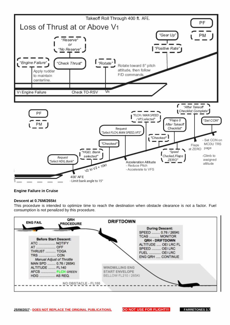
25/08/2017 - DOES NOT REPLACE THE ORIGINAL PUBLICATIONS. DO NOT USE FOR FLIGHT!!! FARRETONES 3.7
Engine Failure in Cruise
Descent at 0.76M/265kt
This procedure is intended to optimize time to reach the destination when obstacle clearance is not a factor. Fuel consumption is not penalized by this procedure.
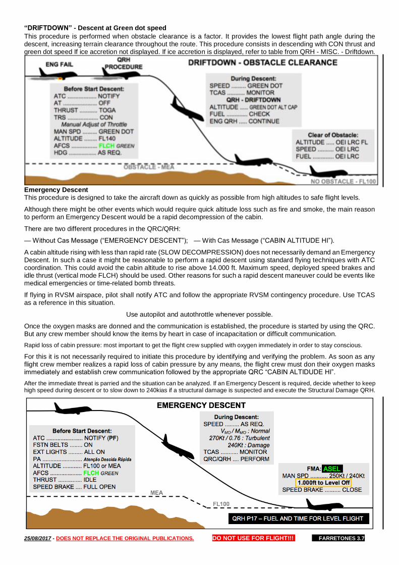
25/08/2017 - DOES NOT REPLACE THE ORIGINAL PUBLICATIONS. DO NOT USE FOR FLIGHT!!! FARRETONES 3.7
“DRIFTDOWN” - Descent at Green dot speed
This procedure is performed when obstacle clearance is a factor. It provides the lowest flight path angle during the descent, increasing terrain clearance throughout the route. This procedure consists in descending with CON thrust and green dot speed If ice accretion not displayed. If ice accretion is displayed, refer to table from QRH - MISC. - Driftdown.
Emergency Descent This procedure is designed to take the aircraft down as quickly as possible from high altitudes to safe flight levels.
Although there might be other events which would require quick altitude loss such as fire and smoke, the main reason to perform an Emergency Descent would be a rapid decompression of the cabin.
There are two different procedures in the QRC/QRH:
— Without Cas Message (“EMERGENCY DESCENT”); — With Cas Message (“CABIN ALTITUDE HI”).
A cabin altitude rising with less than rapid rate (SLOW DECOMPRESSION) does not necessarily demand an Emergency Descent. In such a case it might be reasonable to perform a rapid descent using standard flying techniques with ATC coordination. This could avoid the cabin altitude to rise above 14.000 ft. Maximum speed, deployed speed brakes and idle thrust (vertical mode FLCH) should be used. Other reasons for such a rapid descent maneuver could be events like medical emergencies or time-related bomb threats.
If flying in RVSM airspace, pilot shall notify ATC and follow the appropriate RVSM contingency procedure. Use TCAS as a reference in this situation.
Use autopilot and autothrottle whenever possible.
Once the oxygen masks are donned and the communication is established, the procedure is started by using the QRC. But any crew member should know the items by heart in case of incapacitation or difficult communication.
Rapid loss of cabin pressure: most important to get the flight crew supplied with oxygen immediately in order to stay conscious.
For this it is not necessarily required to initiate this procedure by identifying and verifying the problem. As soon as any flight crew member realizes a rapid loss of cabin pressure by any means, the flight crew must don their oxygen masks immediately and establish crew communication followed by the appropriate QRC “CABIN ALTIDUDE HI”.
After the immediate threat is parried and the situation can be analyzed. If an Emergency Descent is required, decide whether to keep high speed during descent or to slow down to 240kias if a structural damage is suspected and execute the Structural Damage QRH.
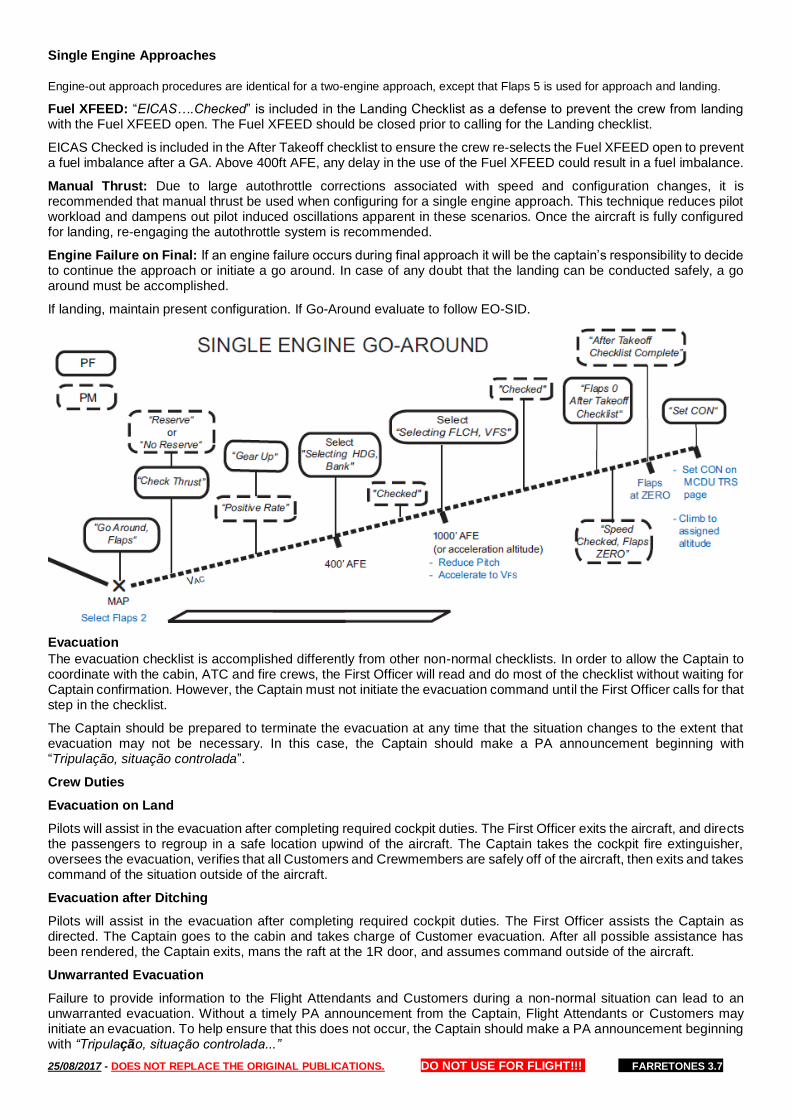
25/08/2017 - DOES NOT REPLACE THE ORIGINAL PUBLICATIONS. DO NOT USE FOR FLIGHT!!! FARRETONES 3.7
Single Engine Approaches
Engine-out approach procedures are identical for a two-engine approach, except that Flaps 5 is used for approach and landing.
Fuel XFEED: “EICAS….Checked” is included in the Landing Checklist as a defense to prevent the crew from landing with the Fuel XFEED open. The Fuel XFEED should be closed prior to calling for the Landing checklist.
EICAS Checked is included in the After Takeoff checklist to ensure the crew re-selects the Fuel XFEED open to prevent a fuel imbalance after a GA. Above 400ft AFE, any delay in the use of the Fuel XFEED could result in a fuel imbalance.
Manual Thrust: Due to large autothrottle corrections associated with speed and configuration changes, it is recommended that manual thrust be used when configuring for a single engine approach. This technique reduces pilot workload and dampens out pilot induced oscillations apparent in these scenarios. Once the aircraft is fully configured for landing, re-engaging the autothrottle system is recommended.
Engine Failure on Final: If an engine failure occurs during final approach it will be the captain’s responsibility to decide to continue the approach or initiate a go around. In case of any doubt that the landing can be conducted safely, a go around must be accomplished.
If landing, maintain present configuration. If Go-Around evaluate to follow EO-SID.
Evacuation
The evacuation checklist is accomplished differently from other non-normal checklists. In order to allow the Captain to coordinate with the cabin, ATC and fire crews, the First Officer will read and do most of the checklist without waiting for Captain confirmation. However, the Captain must not initiate the evacuation command until the First Officer calls for that step in the checklist.
The Captain should be prepared to terminate the evacuation at any time that the situation changes to the extent that evacuation may not be necessary. In this case, the Captain should make a PA announcement beginning with “Tripulação, situação controlada”.
Crew Duties
Evacuation on Land
Pilots will assist in the evacuation after completing required cockpit duties. The First Officer exits the aircraft, and directs the passengers to regroup in a safe location upwind of the aircraft. The Captain takes the cockpit fire extinguisher, oversees the evacuation, verifies that all Customers and Crewmembers are safely off of the aircraft, then exits and takes command of the situation outside of the aircraft.
Evacuation after Ditching
Pilots will assist in the evacuation after completing required cockpit duties. The First Officer assists the Captain as directed. The Captain goes to the cabin and takes charge of Customer evacuation. After all possible assistance has been rendered, the Captain exits, mans the raft at the 1R door, and assumes command outside of the aircraft.
Unwarranted Evacuation
Failure to provide information to the Flight Attendants and Customers during a non-normal situation can lead to an unwarranted evacuation. Without a timely PA announcement from the Captain, Flight Attendants or Customers may initiate an evacuation. To help ensure that this does not occur, the Captain should make a PA announcement beginning with “Tripulação, situação controlada...”
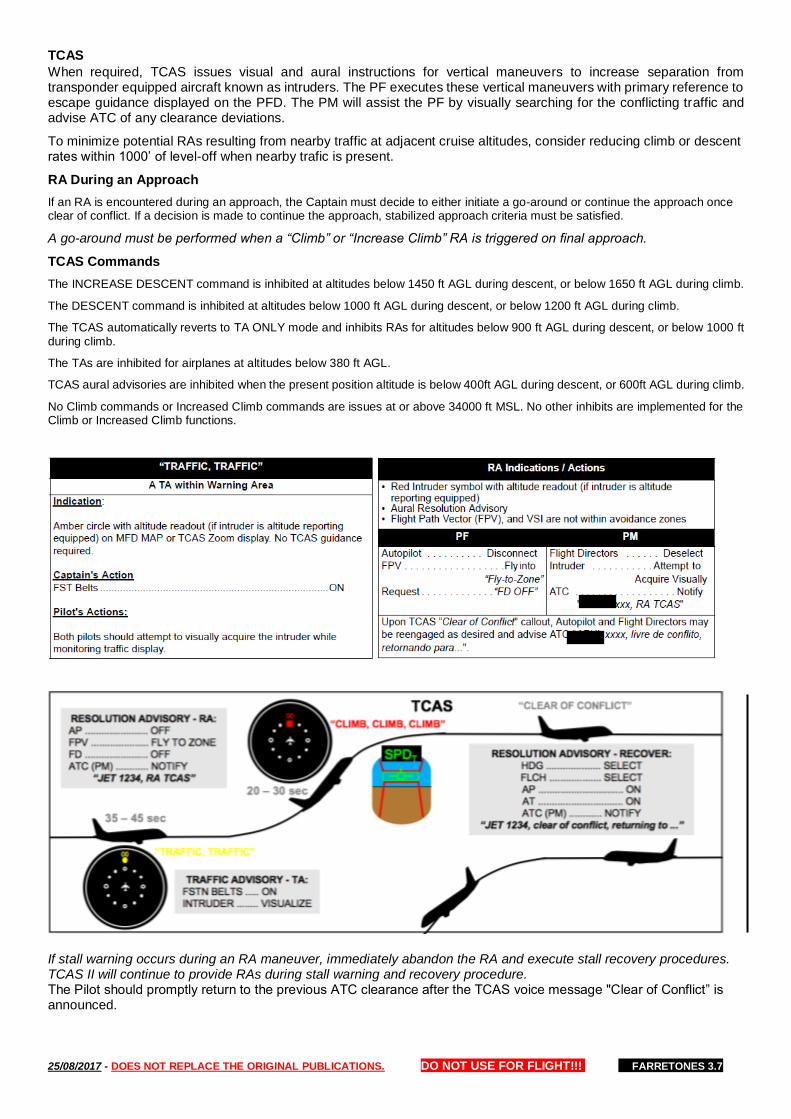
25/08/2017 - DOES NOT REPLACE THE ORIGINAL PUBLICATIONS. DO NOT USE FOR FLIGHT!!! FARRETONES 3.7
TCAS
When required, TCAS issues visual and aural instructions for vertical maneuvers to increase separation from transponder equipped aircraft known as intruders. The PF executes these vertical maneuvers with primary reference to escape guidance displayed on the PFD. The PM will assist the PF by visually searching for the conflicting traffic and advise ATC of any clearance deviations.
To minimize potential RAs resulting from nearby traffic at adjacent cruise altitudes, consider reducing climb or descent rates within 1000’ of level-off when nearby trafic is present.
RA During an Approach
If an RA is encountered during an approach, the Captain must decide to either initiate a go-around or continue the approach once clear of conflict. If a decision is made to continue the approach, stabilized approach criteria must be satisfied.
A go-around must be performed when a “Climb” or “Increase Climb” RA is triggered on final approach.
TCAS Commands
The INCREASE DESCENT command is inhibited at altitudes below 1450 ft AGL during descent, or below 1650 ft AGL during climb.
The DESCENT command is inhibited at altitudes below 1000 ft AGL during descent, or below 1200 ft AGL during climb.
The TCAS automatically reverts to TA ONLY mode and inhibits RAs for altitudes below 900 ft AGL during descent, or below 1000 ft during climb.
The TAs are inhibited for airplanes at altitudes below 380 ft AGL.
TCAS aural advisories are inhibited when the present position altitude is below 400ft AGL during descent, or 600ft AGL during climb.
No Climb commands or Increased Climb commands are issues at or above 34000 ft MSL. No other inhibits are implemented for the Climb or Increased Climb functions.
If stall warning occurs during an RA maneuver, immediately abandon the RA and execute stall recovery procedures. TCAS II will continue to provide RAs during stall warning and recovery procedure. The Pilot should promptly return to the previous ATC clearance after the TCAS voice message "Clear of Conflict” is announced.
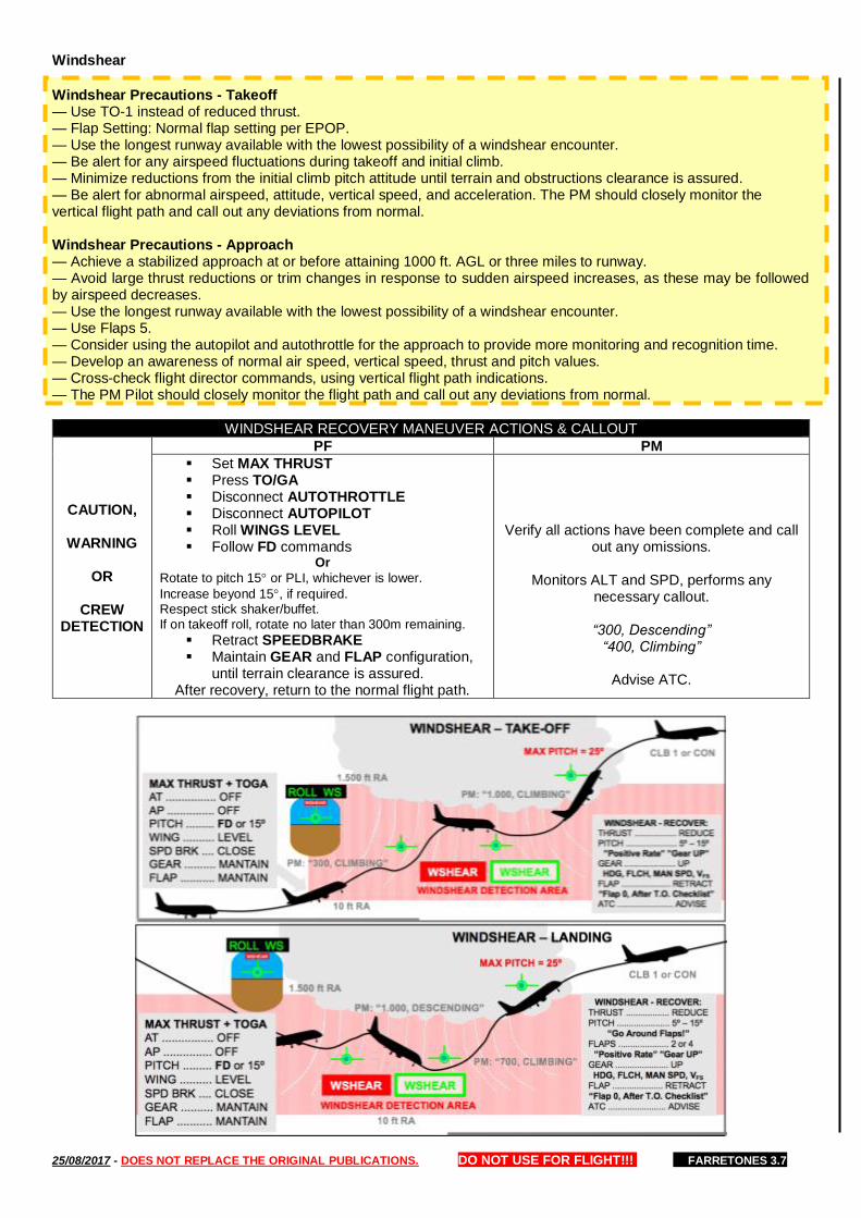
25/08/2017 - DOES NOT REPLACE THE ORIGINAL PUBLICATIONS. DO NOT USE FOR FLIGHT!!! FARRETONES 3.7
Windshear
Windshear Precautions - Takeoff — Use TO-1 instead of reduced thrust. — Flap Setting: Normal flap setting per EPOP. — Use the longest runway available with the lowest possibility of a windshear encounter. — Be alert for any airspeed fluctuations during takeoff and initial climb. — Minimize reductions from the initial climb pitch attitude until terrain and obstructions clearance is assured. — Be alert for abnormal airspeed, attitude, vertical speed, and acceleration. The PM should closely monitor the vertical flight path and call out any deviations from normal. Windshear Precautions - Approach — Achieve a stabilized approach at or before attaining 1000 ft. AGL or three miles to runway. — Avoid large thrust reductions or trim changes in response to sudden airspeed increases, as these may be followed by airspeed decreases. — Use the longest runway available with the lowest possibility of a windshear encounter. — Use Flaps 5. — Consider using the autopilot and autothrottle for the approach to provide more monitoring and recognition time. — Develop an awareness of normal air speed, vertical speed, thrust and pitch values. — Cross-check flight director commands, using vertical flight path indications. — The PM Pilot should closely monitor the flight path and call out any deviations from normal.
WINDSHEAR RECOVERY MANEUVER ACTIONS & CALLOUT
CAUTION,
WARNING
OR
CREW DETECTION
PF PM
▪ Set MAX THRUST ▪ Press TO/GA ▪ Disconnect AUTOTHROTTLE ▪ Disconnect AUTOPILOT ▪ Roll WINGS LEVEL ▪ Follow FD commands
Or
Rotate to pitch 15 or PLI, whichever is lower.
Increase beyond 15, if required. Respect stick shaker/buffet. If on takeoff roll, rotate no later than 300m remaining.
▪ Retract SPEEDBRAKE ▪ Maintain GEAR and FLAP configuration,
until terrain clearance is assured. After recovery, return to the normal flight path.
Verify all actions have been complete and call out any omissions.
Monitors ALT and SPD, performs any
necessary callout.
“300, Descending” “400, Climbing”
Advise ATC.
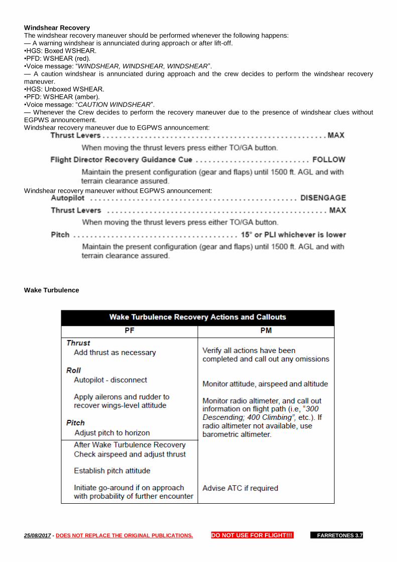
25/08/2017 - DOES NOT REPLACE THE ORIGINAL PUBLICATIONS. DO NOT USE FOR FLIGHT!!! FARRETONES 3.7
Windshear Recovery The windshear recovery maneuver should be performed whenever the following happens: — A warning windshear is annunciated during approach or after lift-off. •HGS: Boxed WSHEAR. •PFD: WSHEAR (red). •Voice message: “WINDSHEAR, WINDSHEAR, WINDSHEAR”. — A caution windshear is annunciated during approach and the crew decides to perform the windshear recovery maneuver. •HGS: Unboxed WSHEAR. •PFD: WSHEAR (amber). •Voice message: “CAUTION WINDSHEAR”. — Whenever the Crew decides to perform the recovery maneuver due to the presence of windshear clues without EGPWS announcement. Windshear recovery maneuver due to EGPWS announcement:
Windshear recovery maneuver without EGPWS announcement:
Wake Turbulence
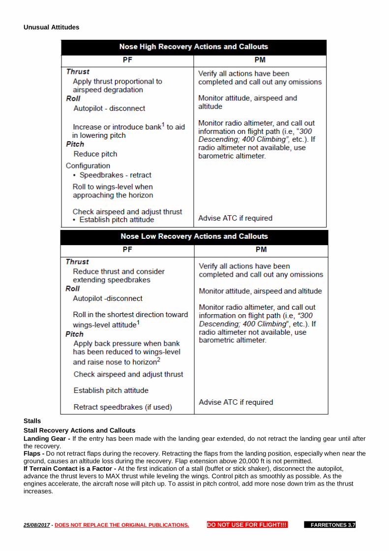
25/08/2017 - DOES NOT REPLACE THE ORIGINAL PUBLICATIONS. DO NOT USE FOR FLIGHT!!! FARRETONES 3.7
Unusual Attitudes
Stalls
Stall Recovery Actions and Callouts
Landing Gear - If the entry has been made with the landing gear extended, do not retract the landing gear until after the recovery. Flaps - Do not retract flaps during the recovery. Retracting the flaps from the landing position, especially when near the ground, causes an altitude loss during the recovery. Flap extension above 20,000 ft is not permitted. If Terrain Contact is a Factor - At the first indication of a stall (buffet or stick shaker), disconnect the autopilot, advance the thrust levers to MAX thrust while leveling the wings. Control pitch as smoothly as possible. As the engines accelerate, the aircraft nose will pitch up. To assist in pitch control, add more nose down trim as the thrust increases.
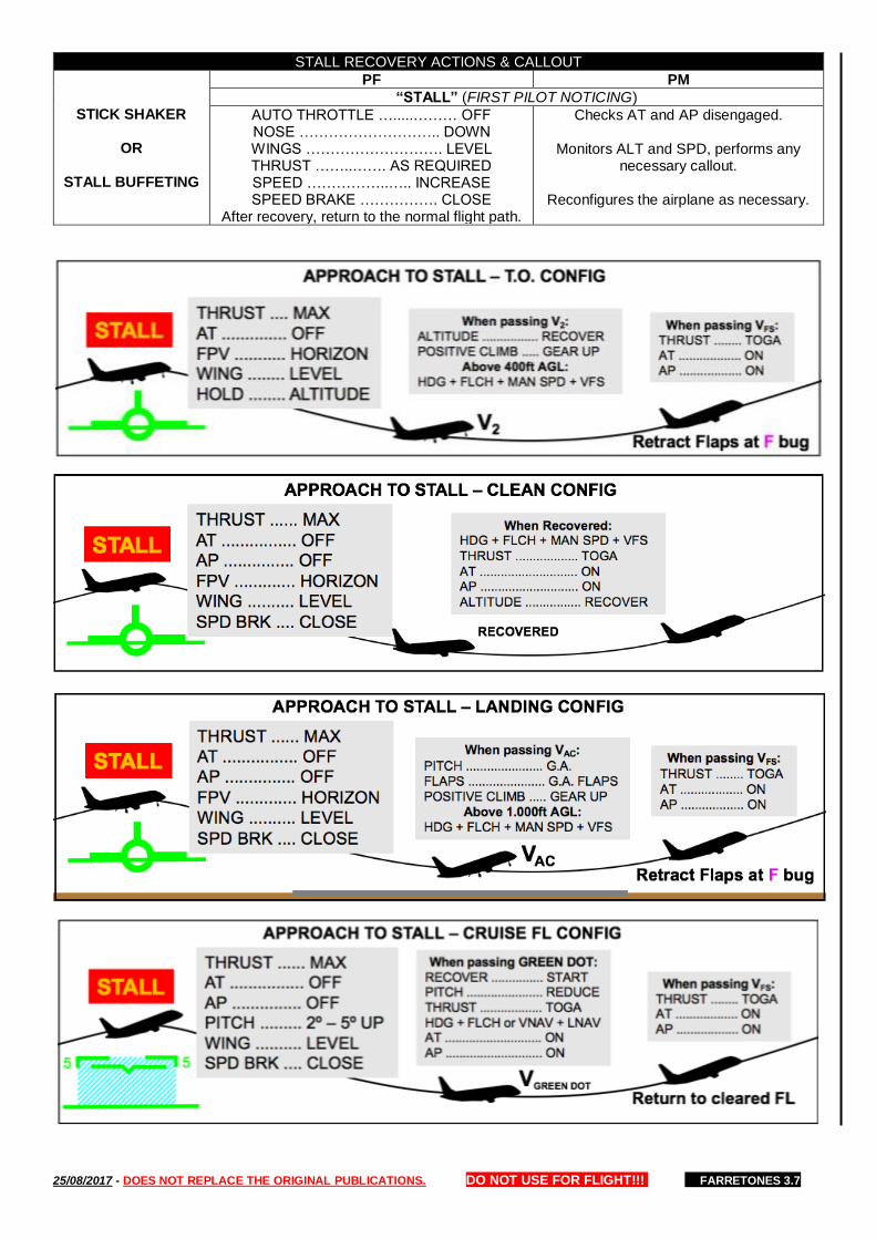
25/08/2017 - DOES NOT REPLACE THE ORIGINAL PUBLICATIONS. DO NOT USE FOR FLIGHT!!! FARRETONES 3.7
STALL RECOVERY ACTIONS & CALLOUT
STICK SHAKER
OR
STALL BUFFETING
PF PM
“STALL” (FIRST PILOT NOTICING)
AUTO THROTTLE ….....……… OFF NOSE ……………………….. DOWN WINGS ………………………. LEVEL THRUST ……..……. AS REQUIRED SPEED ……………..….. INCREASE SPEED BRAKE ……………. CLOSE
After recovery, return to the normal flight path.
Checks AT and AP disengaged.
Monitors ALT and SPD, performs any necessary callout.
Reconfigures the airplane as necessary.
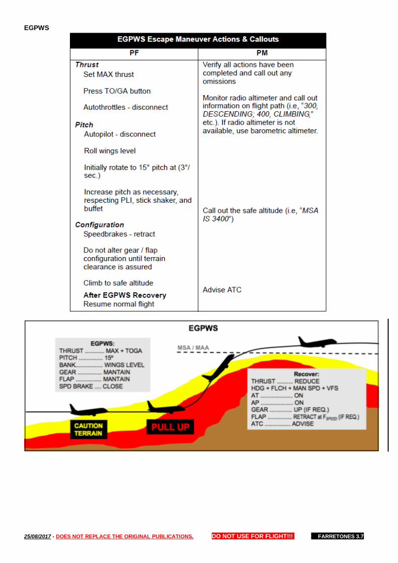
25/08/2017 - DOES NOT REPLACE THE ORIGINAL PUBLICATIONS. DO NOT USE FOR FLIGHT!!! FARRETONES 3.7
EGPWS
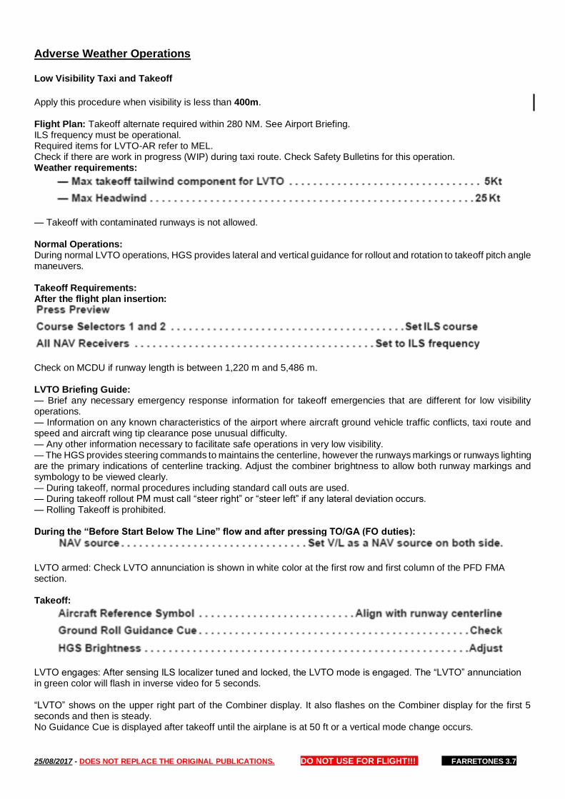
25/08/2017 - DOES NOT REPLACE THE ORIGINAL PUBLICATIONS. DO NOT USE FOR FLIGHT!!! FARRETONES 3.7
Adverse Weather Operations Low Visibility Taxi and Takeoff
Apply this procedure when visibility is less than 400m. Flight Plan: Takeoff alternate required within 280 NM. See Airport Briefing. ILS frequency must be operational. Required items for LVTO-AR refer to MEL. Check if there are work in progress (WIP) during taxi route. Check Safety Bulletins for this operation. Weather requirements:
— Takeoff with contaminated runways is not allowed. Normal Operations: During normal LVTO operations, HGS provides lateral and vertical guidance for rollout and rotation to takeoff pitch angle maneuvers. Takeoff Requirements: After the flight plan insertion:
Check on MCDU if runway length is between 1,220 m and 5,486 m. LVTO Briefing Guide: — Brief any necessary emergency response information for takeoff emergencies that are different for low visibility operations. — Information on any known characteristics of the airport where aircraft ground vehicle traffic conflicts, taxi route and speed and aircraft wing tip clearance pose unusual difficulty. — Any other information necessary to facilitate safe operations in very low visibility. — The HGS provides steering commands to maintains the centerline, however the runways markings or runways lighting are the primary indications of centerline tracking. Adjust the combiner brightness to allow both runway markings and symbology to be viewed clearly. — During takeoff, normal procedures including standard call outs are used. — During takeoff rollout PM must call “steer right” or “steer left” if any lateral deviation occurs. — Rolling Takeoff is prohibited. During the “Before Start Below The Line” flow and after pressing TO/GA (FO duties):
LVTO armed: Check LVTO annunciation is shown in white color at the first row and first column of the PFD FMA section. Takeoff:
LVTO engages: After sensing ILS localizer tuned and locked, the LVTO mode is engaged. The “LVTO” annunciation in green color will flash in inverse video for 5 seconds. “LVTO” shows on the upper right part of the Combiner display. It also flashes on the Combiner display for the first 5 seconds and then is steady. No Guidance Cue is displayed after takeoff until the airplane is at 50 ft or a vertical mode change occurs.

25/08/2017 - DOES NOT REPLACE THE ORIGINAL PUBLICATIONS. DO NOT USE FOR FLIGHT!!! FARRETONES 3.7
Abnormal Operations: There are two failure possibilities during LVTO operation and they can be monitored through FMA annunciations on the PFD. Example 1: Failure between 40 and 80 kt. If the LVTO mode fails while IAS is between 40 and 80 kt, the “LVTO” annunciation in red color will flash in inverse video for 5 seconds in the first row and second column of the PFD FMA, then it stays in red color. In this case of LVTO Mode disengagement (also occurs during failure to engage), the annunciation LVTO WRN will be displayed on the PFD. Also the “LVTO WRN” annunciations are displayed in both HGS & PFDs even if only one HUD detects this condition. LVTO Warning: ANNUNCIATION: LVTO WRN NO LVTO REJECTED TAKEOFF PROCEDURE. . . . . . . . . . . . . . . . . . . . . . . . . . . . . . . . . . ACCOMPLISH The rejected takeoff procedure must be performed unless the takeoff is continued under visual conditions and the airplane position assures a safe takeoff. Example 2: Failure below 49 kt or above 80 kt. An amber “LVTO” is displayed on the PFD to indicate LVTO has lost capability below 40 kt or above 80 kt. This allows the pilot to safely abort the takeoff at low speeds or continue the takeoff at his discretion for speeds approaching V1. The annunciation is on the right side of the top mode line of the PFD. The annunciation flashes inverse video for the first 5 seconds on the PFD and then is steady on its usual background (“NO LVTO” shows on the Combiner display). LVTO Caution: ANNUNCIATION: NO LVTO The flight crew must establish visual cues in order to continue or reject the takeoff.
Additional Procedures for visibility below 400m: Two Engines taxi required. Accomplish all flows and checklists through Before Takeoff (To The Line) prior to taxi. TO-1 takeoff required (FLEX TO allowed). QRH Additional Procedures: When the reported weather is less than standard takeoff minimums (RVR 800m), the Low Visibility takeoff guidance found in the QRH - Additional Procedures must be referenced. Whenever possible, this should be accomplished at the gate prior to pushback.
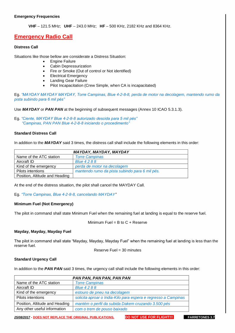
25/08/2017 - DOES NOT REPLACE THE ORIGINAL PUBLICATIONS. DO NOT USE FOR FLIGHT!!! FARRETONES 3.7
Emergency Frequencies
VHF – 121.5 MHz; UHF – 243.0 MHz; HF – 500 KHz, 2182 KHz and 8364 KHz.
Emergency Radio Call Distress Call
Situations like those bellow are considerate a Distress Situation:
• Engine Failure
• Cabin Depressurization
• Fire or Smoke (Out of control or Not identified)
• Electrical Emergency
• Landing Gear Failure
• Pilot Incapacitation (Crew Simple, when CA is incapacitated)
Eg. “MAYDAY MAYDAY MAYDAY, Torre Campinas, Blue 4-2-8-8, perda de motor na decolagem, mantendo rumo da
pista subindo para 6 mil pés”
Use MAYDAY or PAN PAN at the beginning of subsequent messages (Annex 10 ICAO 5.3.1.3). Eg. “Ciente, MAYDAY Blue 4-2-8-8 autorizado descida para 5 mil pés”
“Campinas, PAN PAN Blue 4-2-8-8 iniciando o procedimento”
Standard Distress Call
In addition to the MAYDAY said 3 times, the distress call shall include the following elements in this order:
MAYDAY, MAYDAY, MAYDAY
Name of the ATC station Torre Campinas
Aircraft ID Blue 4 2 8 8
Kind of the emergency perda de motor na decolagem
Pilots intentions mantendo rumo da pista subindo para 6 mil pés.
Position, Altitude and Heading
At the end of the distress situation, the pilot shall cancel the MAYDAY Call.
Eg. “Torre Campinas, Blue 4-2-8-8, cancelando MAYDAY”
Minimum Fuel (Not Emergency)
The pilot in command shall state Minimum Fuel when the remaining fuel at landing is equal to the reserve fuel.
Minimum Fuel = B to C + Reserve Mayday, Mayday, Mayday Fuel
The pilot in command shall state “Mayday, Mayday, Mayday Fuel” when the remaining fuel at landing is less than the reserve fuel.
Reserve Fuel = 30 minutes Standard Urgency Call
In addition to the PAN PAN said 3 times, the urgency call shall include the following elements in this order:
PAN PAN, PAN PAN, PAN PAN
Name of the ATC station Torre Campinas
Aircraft ID Blue 4 2 8 8
Kind of the emergency estouro de pneu na decolagem
Pilots intentions solicita aproar o India-Kilo para espera e regresso a Campinas
Position, Altitude and Heading mantém o perfil da subida Dakem cruzando 3.500 pés
Any other useful information com o trem de pouso baixado
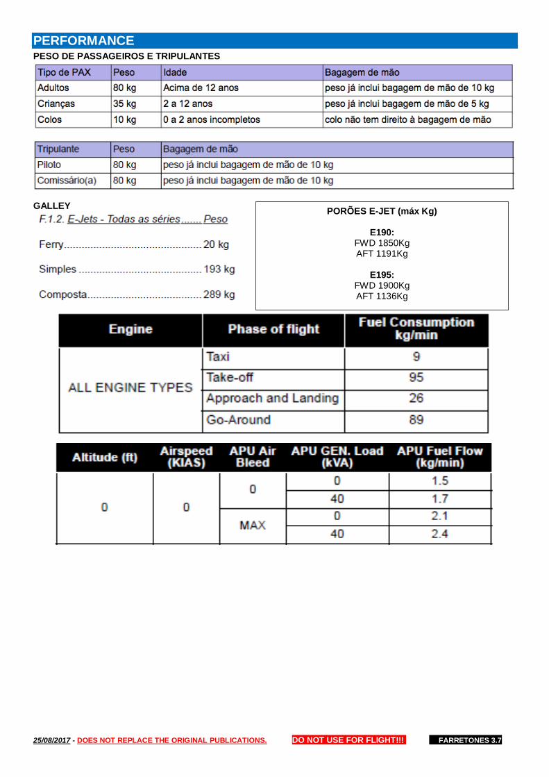
25/08/2017 - DOES NOT REPLACE THE ORIGINAL PUBLICATIONS. DO NOT USE FOR FLIGHT!!! FARRETONES 3.7
PERFORMANCE PESO DE PASSAGEIROS E TRIPULANTES
GALLEY
PORÕES E-JET (máx Kg)
E190: FWD 1850Kg AFT 1191Kg
E195:
FWD 1900Kg AFT 1136Kg
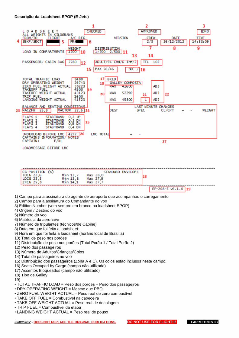
25/08/2017 - DOES NOT REPLACE THE ORIGINAL PUBLICATIONS. DO NOT USE FOR FLIGHT!!! FARRETONES 3.7
Descrição da Loadsheet EPOP (E-Jets)
1) Campo para a assinatura do agente de aeroporto que acompanhou o carregamento 2) Campo para a assinatura do Comandante do voo 3) Edition Number (vem sempre em branco na loadsheet EPOP) 4) Origem / Destino do voo 5) Número do voo 6) Matrícula da aeronave 7) Número de tripulantes (técnicos/de Cabine) 8) Data em que foi feita a loadsheet 9) Hora em que foi feita a loadsheet (horário local de Brasília) 10) Total de peso nos porões 11) Distribuição de peso nos porões (Total Porão 1 / Total Porão 2) 12) Peso dos passageiros 13) Número de Adultos/Crianças/Colos 14) Total de passageiros no voo 15) Distribuição dos passageiros (Zona A e C). Os colos estão inclusos neste campo. 16) Seats Occuped by Cargo (campo não utilizado) 17) Assentos Bloqueados (campo não utilizado) 18) Tipo de Galley 19) • TOTAL TRAFFIC LOAD = Peso dos porões + Peso dos passageiros • DRY OPERATING WEIGHT = Mesmo que PBO • ZERO FUEL WEIGHT ACTUAL = Peso real de zero combustível • TAKE OFF FUEL = Combustível na cabeceira • TAKE OFF WEIGHT ACTUAL = Peso real de decolagem • TRIP FUEL = Combustível da etapa • LANDING WEIGHT ACTUAL = Peso real de pouso

25/08/2017 - DOES NOT REPLACE THE ORIGINAL PUBLICATIONS. DO NOT USE FOR FLIGHT!!! FARRETONES 3.7
20) • ZERO FUEL WEIGHT MAX Peso máximo estrutural de zero combustível • TAKE OFF WEIGHT MAX Peso máximo de decolagem. É menor entre: a. Máximo estrutural de decolagem b. Máximo por performance de decolagem c. Máximo por PCN da pista de decolagem • LANDING WEIGHT MAX Peso máximo de pouso. É o menor entre: a. Máximo estrutural de pouso b. Máximo por performance de pouso c. Máximo por PCN da pista de pouso 21) Indica o peso máximo que limita o voo (é a linha que tem a menor diferença entre o peso real e o peso máximo, ou seja, o underload, indicado no item 26) 22) Adjustment (campo não utilizado) 23) CG Zero Combustível 24) CG de Decolagem 25) Stab Trim 26) Peso disponível (é o que a aeronave ainda pode carregar no voo) 27) Informações de Last Minute Change • DEST – Aeroporto de destino da LMC • SPEC – Especificação da LMC (tipo de passageiro, bagagem ou carga) • CL / CPT – Compartimento onde está embarcando a LMC (CL=classe, CPT=porão) • WEIGHT = Valor em peso (sinal de + significa peso embarcando / sinal de – significa peso desembarcando) 28) Envelope de balanceamento
LAST MINUTE CHANGE
De acordo com a IAC 121-1001, LMC é a quantidade de peso que pode embarcar ou desembarcar do avião sem que haja a necessidade de se fazer uma nova loadsheet. Os valores seguem uma proporcionalidade em relação ao porte de cada modelo de aeronave da frota e segue abaixo: • A LMC inclui qualquer item, independentemente de sua natureza, abrangendo portanto passageiros, ocupantes de jumpseat, o conteúdo dos porões/compartimentos de carga e combustível. • As modificações que permitem aplicar a regra de LMC consistem exclusivamente de embarque ou desembarque, não uma combinação delas. Por exemplo, não é aplicável a qualquer remanejamento de peso entre os porões, o que equivaleria a um desembarque e um embarque consecutivos. • A LMC também não pode ultrapassar o UNDERLOAD. • Para efeito de LMC, o ocupante do jumpseat irá ser identificado na loadsheet como JUMP e considerado com 75 kg. • As mudanças de última hora deverão ser informadas de maneira clara na loadsheet por meio de anotações no campo LAST MINUTE CHANGES conforme instrução abaixo: A. DEST: Aeroporto de destino da LMC. B. SPEC: adulto (ADT), criança (CHD), infante (INF), Jumpseat, bagagem (BAG), carga (CGA), combustível (FUEL) C. CL/CPT: clientes classe Y, bagagem e/ou carga H1 (porão dianteiro1) e H2 (porão traseiro) D. + - : símbolo “+” para peso acrescido e símbolo “–” para peso retirado da aeronave E. WEIGHT: peso em kg F. LMC TOTAL: peso total embarcado ou desembarcado G. O preenchimento do campo LMC é feito pelo agente de aeroporto e entregue ao CAPT escrito nas duas vias.
NOTA Em caso de alteração no número de PAX, corrigir o campo TTL, vide exemplo abaixo. Em caso de alteração devido
ocupação do(s) jumpseat(s), corrigir o campo CREW.

25/08/2017 - DOES NOT REPLACE THE ORIGINAL PUBLICATIONS. DO NOT USE FOR FLIGHT!!! FARRETONES 3.7
COMBUSTÍVEL MÍNIMO REQUERIDO PARA DESPACHO
E-Jets - RBAC 121.645 (para voos sem redespacho) O avião deve ter combustível suficiente para: A. voar até o aeródromo para onde foi despachado ou liberado e pousar nesse aeródromo; B. após isso, voar por um período igual a 10% do tempo total requerido para voar do aeródromo de partida até o pouso no aeródromo para o qual foi despachado ou liberado; C. após isso, voar e pousar no aeródromo de alternativa mais distante listado no despacho ou liberação do voo (se um aeródromo de alternativa for requerido); e D. após isso, voar mais 30 minutos, em velocidade de espera, a 1500 pés de altura sobre o aeródromo de alternativa mais distante, em condições de temperatura padrão.
CONSUMO NO TAXI - OPERAÇÃO BIMOTOR
E-190 / E-195 • 9 kg/min A. APU: 2 kg/min
LMC PARA PLANO DE VOO
valores abaixo como variação de peso limite para não haver necessidade de confecção de novo plano de voo.
E190 = 900KG
Consumo a mais por cada 500 kg de peso extra no voo = E190 = 16KG/H
REDESPACHO
Procedimentos do Comandante do Voo: Ao receber a “Mensagem de Redespacho” com informações meteorológicas e do combustível mínimo requerido, o Comandante decidirá sobre a possibilidade de prosseguir ou não para o destino, considerando todas as informações disponíveis.
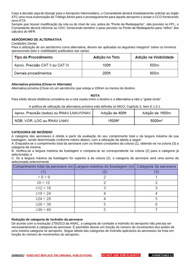
25/08/2017 - DOES NOT REPLACE THE ORIGINAL PUBLICATIONS. DO NOT USE FOR FLIGHT!!! FARRETONES 3.7
Caso a decisão seja de divergir para o Aeroporto Intermediário, o Comandante deverá imediatamente solicitar ao órgão ATC uma nova Autorização de Tráfego Aéreo para o prosseguimento para aquele aeroporto e avisar o CCO fornecendo novo ETA. Sempre que houver modificação da rota ou do nível de voo, antes do “Ponto de Redespacho”, não previsto no FPL, o Comandante deverá informar ao CDV, fornecendo também o peso previsto no Ponto de Redespacho para “refino” dos cálculos do MFR.
AERÓDROMO DE ALTERNATIVA
Condições Gerais Para a utilização de um aeródromo como alternativa, devem ser aplicadas as seguintes margens* sobre os mínimos operacionais (teto e visibilidade) publicados nas cartas:
Alternativa próxima (Close-in Alternate)
Alternativa próxima (Close-in) um aeródromo que esteja a 100nm ou menos do destino.
NOTA Para efeito dessa distância considera-se a rota voada entre o destino e a alternativa e não o “great circle”.
A política de utilização da alternativa próxima está definida no MGO, Capítulo 3, Item E.1.5.1.
CATEGORIA DE INCÊNDIO
A categoria das aeronaves é obtida a partir da avaliação do seu comprimento total e da largura máxima da sua fuselagem, sendo determinada conforme roteiro abaixo, com a utilização da tabela a seguir: A. Enquadra-se o comprimento total da aeronave com os limites constantes da coluna (1), obtendo-se na coluna (3) a categoria da mesma; B. Verifica-se a largura máxima da fuselagem e compara-se ao correspondente na coluna (2) para a categoria já selecionada; e C. Se a largura máxima da fuselagem for superior à da coluna (2), a categoria da aeronave será uma acima da selecionada anteriormente
Redução de categoria de incêndio da aeronave
De acordo com a resolução 279/2013 da ANAC, a categoria de combate a incêndio do aeroporto não precisa ser necessariamente a categoria da aeronave. É permitido desvio em função do número de movimentos dos aviões de uma mesma categoria no aeroporto. Segue tabela das categorias de incêndio aplicáveis às aeronaves da frota em função do número de movimentos do aeroporto.

25/08/2017 - DOES NOT REPLACE THE ORIGINAL PUBLICATIONS. DO NOT USE FOR FLIGHT!!! FARRETONES 3.7
Redução de categoria de incêndio do aeroporto por NOTAM
Quando houver redução da categoria de incêndio do aeroporto por NOTAM é permitido manter a operação desde que a desasagem seja de no máximo 2 níves abaixo em relação ao NPCR. Entretanto, a operação com o NPCE defasado possui um prazo máximo, dependendo da classe do aeródromo, conforme tabela abaixo:
ANÁLISE DE DECOLAGEM (E-JETS)
Q.1. Introdução (E-Jets) O EPOP é a ferramenta primária para os cálculos de performance de decolagem a bordo. • Em caso de pane dupla de EFB o DOV enviará para a tripulação uma análise de decolagem em Formato Reduzido. Ver a descrição detalhada desse tipo de análise no item a seguir. Q.2. Análise de decolagem - Formato Reduzido (E-Jets) Esse tipo de análise é gerada em tempo real pelo DOV através do software Takeoff Module. É utilizada quando o EPOP estiver inoperante. As análises do Takeoff Module consideram algumas condições que são fixas que não podem ser alteradas pelo DOV. São elas: • T/O-1 • ECS OFF • Anti-ice off 1. OBSERVAÇÕES • O QNH desse tipo de análise é variável. Como é rodada em tempo real, será utilizado o QNH previsto para a decolagem ao invés do valor fixo 1013,25 hPa. • Velocidade de decolagem - As velocidades de decolagem são válidas para o peso da análise (MTOW) e também para qualquer ATOW abaixo deste. • Redução de potência - Através desse tipo de análise é possível redução de potência apenas pelo método temperatura assumida (FLEX) limitado pela temperatura mais alta da análise. • Anti-ice ON - O Takeoff Module não calcula performance com Anti-ice ON. Nesse caso o DOV deverá efetuar a análise de pista via EPOP, que possui essa opção.
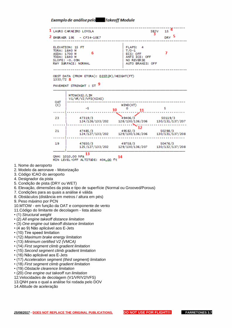
25/08/2017 - DOES NOT REPLACE THE ORIGINAL PUBLICATIONS. DO NOT USE FOR FLIGHT!!! FARRETONES 3.7
1. Nome do aeroporto 2. Modelo da aeronave - Motorização 3. Código ICAO do aeroporto 4. Designador da pista 5. Condição de pista (DRY ou WET) 6. Elevação, dimensões da pista e tipo de superfície (Normal ou Grooved/Porous) 7. Condições para as quais a análise é válida 8. Obstáculos (distância em metros / altura em pés) 9. Peso máximo por PCN 10.MTOW - em função da OAT e componente de vento 11.Código do limitante de decolagem - lista abaixo • (1) Structural weight • (2) All engine takeoff distance limitation • (3) One engine out takeoff distance limitation • (4 ao 9) Não aplicável aos E-Jets • (10) Tire speed limitation • (12) Maximum brake energy limitation • (13) Minimum certified V2 (VMCA) • (14) First segment climb gradient limitation • (15) Second segment climb gradient limitation • (16) Não aplicável aos E-Jets • (17) Acceleration segment (third segment) limitation • (18) First segment climb gradient limitation • (19) Obstacle clearence limitation • (20) One engine out takeoff run limitation 12.Velocidades de decolagem (V1/VR/V2/VFS) 13.QNH para o qual a análise foi rodada pelo DOV 14.Altitude de aceleração

25/08/2017 - DOES NOT REPLACE THE ORIGINAL PUBLICATIONS. DO NOT USE FOR FLIGHT!!! FARRETONES 3.7
LIMITANTES DE PERFORMANCE DE DECOLAGEM (E-JETS)
A análise de decolagem calcula todos os limitantes listados e adota como MTOW pelo sempre pelo menor deles todos. R.1. Field Length AEO (all engine takeoff distance) Peso máximo que permite em uma decolagem sem perda de motor atingir 35 ft com ainda 15% de sobra de pista. R.2. Field Length OEI (one engine out takeoff distance) Peso máximo que permite: 1. Acelerar com os dois motores até a V1, iniciar rejeição de decolagem nesse ponto e completar parada até o final da pista ou stopway (onde houver). 2. Acelerar com os dois motores até a V1 e continuar a decolagem deste ponto em diante com apenas um motor alcançando 35 ft ao cruzar o fim da pista ou clearway (onde houver).
NOTA Para pista molhada o cruzamento do fim da pista é de 15 ft (não é considerada a clearway para WET)
R.3. Approach Climb OEI (Go Around limitation) Peso máximo que permite arremetida monomotor no aeroporto de origem no caso de retorno após a decolagem. O gradiente considerado para este cálculo é de 2,1%. R.4. Tire Speed Peso máximo de decolagem em função da velocidade máxima dos pneus. R.5. First segment (first segment climb gradient) Peso máximo que permite gradiente positivo no primeiro segmento de decolagem com um motor inoperante. R.6. Second segment (second segment gradient) Peso máximo que permite cumprir um gradiente de 2,4% no segundo segmento com um motor inoperante. R.7. Acceleration Segment (third segment gradient) Peso máximo que permite gradiente positivo no primeiro segmento de decolagem com um motor inoperante. R.8. Final Segment (final segment gradient) Peso máximo que permite cumprir um gradiente de 1.2% no segmento final de decolagem com um motor inoperante, flaps up e maximun continuos thrust. R.9. Obstacle Peso máximo que permite livrar na condição de perda de motor na V1 todos os obstáculos listados na análise de decolagem (pela separação mínima regulatória). R.10. Brake Energy (maximum brake energy) Peso máximo que permite rejeição de decolagem sem comprometer a eficiência dos freios.
FLAP ÓTIMO DO EPOP - APLICÁVEL AOS PILOTOS (E-JETS)
Deve-se priorizar o uso do flap ótimo do EPOP pois ele otimiza a redução de potência na decolagem, prolongando a vida útil do motor e reduzindo custos de manutenção.
NOTA A tripulação poderá optar por um flap diferente do ótimo do EPOP sempre que julgar necessário para a manutenção da segurança. O flap ótimo do EPOP nem sempre é o mesmo da navegação/loadsheet porque ele tem uma lógica mais refinada, conforme explicado a seguir. • Lógica do Flap ótimo do EPOP: Flap que gera o maior MTOW para o rate de decolagem selecionado (T/O-1, T/O-2 ou T/O-3) e configuração de ECS utilizada (ON ou OFF). • Lógica do Flap da navegação/loadsheet: Flap que gera o maior MTOW para a configuração fixa T/O-1 e ECS OFF.
ANÁLISE DE POUSO (E-JETS)
A análise de pouso deve ser calculada através do EPOP.

25/08/2017 - DOES NOT REPLACE THE ORIGINAL PUBLICATIONS. DO NOT USE FOR FLIGHT!!! FARRETONES 3.7
OPERAÇÃO EM NARROW RUNWAYS (E-JETS)
Caracteriza-se como Narrow Runways as pistas com menos de 30 metros de largura. Estão certificadas para operação em Narrow Runways as aeronaves E-190 e E-195, devendo-se seguir as limitações e procedimentos a seguir.
NOTA Alguns aeroportos possuem pistas de taxi homologadas para pouso/decolagem. Como essas pistas possuem menos que 30m de largura, também enquadram-se na operação em Narrow Runways. Essas taxiways estarão indicadas no Airport Briefing da localidade.
LIMITAÇÕES
• Largura mínima de pista para pouso e decolagem: 20 metros; • Equipamento mínimo para despacho: A. One Rudder Pedals Nose wheel Steering System Operative (Ref. DDPM 32-53-03); B. Os dois reversos operantes (política da empresa) • Componente máxima de través: Limitations (1700m x 40m or less), ou seja: A. 15 kt - pista seca (DRY) B. 5 kt - pista molhada (WET) • EMERGENCY AND ABNORMAL PROCEDURES (aplicável somente aos pilotos) Ver QRH (Additional Procedures – Narrow Runway Operations)
CÁLCULO DE PERFORMANCE
Decolagem A operação em Narrow Runways resulta em um aumento da Vmcg visando diminuir o desvio lateral no caso de falha de motor. Para que o EPOP considere essa performance na análise das velocidades de decolagem é necessário selecionar YES no box Narrow conforme figura a seguir. Pouso Não há impactos no cálculo de performance de pouso.
Dúvidas frequentes sobre Narrow Runways
A. É necessário que as pistas de táxi constem na tabela de Narrow Runways da EO (Especificações Operativas) para que a operação possa ser realizada? Não. A regra requer que na EO conste apenas as pistas relacionadas a operação regular. Não se enquadram nesse critério portanto as pistas de táxi e as pistas operadas em voos não regulares. B. Na EO é considerado como Narrow Runway as pista com menos de 45 metros de largura, enquanto que este Manual informa que largura mínima para tal é 30 metros. Qual a explicação para essa divergência? 45 metros é o critério de Narrow Runway para a ANAC, qualquer que seja o modelo de aeronave. Para o Embraer Narrow Runway é a pista com menos de 30 metros de largura. Portanto, aplica-se a necessidade do cálculo de performance demonstrada nesse Manual somente para as pistas com menos de 30 metros de largura.
OPERAÇÃO EM PISTAS DE TAXI (E-JETS)
Seguir os procedimentos de Operação em Narrow Runways descritos neste manual visto que as pistas de taxi se enquadram nesta categoria (<30 metros de largura). Também deve ser lido o Airport Briefing do aeroporto, que contem informações importantes como mínimos operacionais, meteorológicos e áreas de giro. As pistas de taxi que constam no ROTAER para eventual operação de decolagem estão cadastradas no EPOP e takeoff Module.
RESISTÊNCIA DO PAVIMENTO – MÉTODO ACN-PCN
Generalidades O método ACN-PCN tem por finalidade a aferição da resistência do pavimento em função das características da aeronave (ACN) e do pavimento (PCN), sendo estruturado de maneira que um pavimento com um determinado valor de PCN seja capaz de suportar, sem restrições, uma aeronave que tenha um valor de ACN inferior ou igual ao valor do PCN do pavimento.
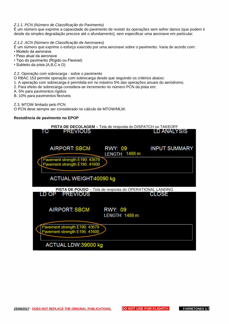
25/08/2017 - DOES NOT REPLACE THE ORIGINAL PUBLICATIONS. DO NOT USE FOR FLIGHT!!! FARRETONES 3.7
Z.1.1. PCN (Número de Classificação do Pavimento) É um número que exprime a capacidade do pavimento de resistir às operações sem sofrer danos (que podem ir desde da simples degradação precoce até o afundamento), sem especificar uma aeronave em particular. Z.1.2. ACN (Número de Classificação de Aeronaves) É um número que exprime o esforço exercido por uma aeronave sobre o pavimento. Varia de acordo com: • Modelo da aeronave • Peso atual da aeronave • Tipo do pavimento (Rígido ou Flexivel) • Subleito da pista (A,B,C e D) Z.2. Operação com sobrecarga - sobre o pavimento O RBAC 153 permite operação com sobrecarga desde que seguindo os critérios abaixo: 1. A operação com sobrecarga é permitida em no máximo 5% das operações anuais do aeródromo. 2. Para efeito de sobrecarga considera-se incremento no número PCN da pista em: A. 5% para pavimentos rígidos B. 10% para pavimentos flexíveis Z.3. MTOW limitado pelo PCN O PCN deve sempre ser considerado no cálculo de MTOW/MLW. Resistência de pavimento no EPOP
PISTA DE DECOLAGEM – Tela de resposta do DISPATCH ou TAKEOFF
PISTA DE POUSO – Tela de resposta do OPERATIONAL LANDING
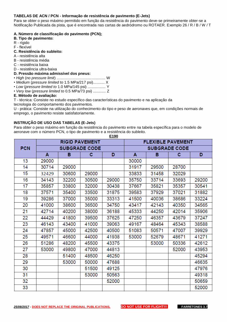
25/08/2017 - DOES NOT REPLACE THE ORIGINAL PUBLICATIONS. DO NOT USE FOR FLIGHT!!! FARRETONES 3.7
TABELAS DE ACN / PCN - Informação de resistência de pavimento (E-Jets)
Para se obter o peso máximo permitido em função da resistência do pavimento deve-se primeiramente obter-se a Notificação Publicada da pista, que é encontrada nas cartas de aedródromo ou ROTAER. Exemplo 26 / R / B / W / T A. Número de classificação do pavimento (PCN); B. Tipo de pavimento: R - rígido F - flexível C. Resistência do subleito: A - resistência alta B - resistência média C - resistência baixa D - resistência ultra-baixa D. Pressão máxima admissível dos pneus: • High (no pressure limit) .............................................. W • Medium (pressure limited to 1.5 MPa/217 psi)........... X • Low (pressure limited to 1.0 MPa/145 psi) ................. Y • Very low (pressure limited to 0.5 MPa/73 psi) ............ Z E. Método de avaliação: T - técnica: Consiste no estudo específico das características do pavimento e na aplicação da tecnologia do comportamento dos pavimentos. U - prática: Consiste na utilização do conhecimento do tipo e peso de aeronaves que, em condições normais de emprego, o pavimento resiste satisfatoriamente.
INSTRUÇÃO DE USO DAS TABELAS (E-Jets)
Para obter o peso máximo em função da resistência do pavimento entre na tabela específica para o modelo de aeronave com o número PCN, o tipo de pavimento e a resistência do subleito.
E190

25/08/2017 - DOES NOT REPLACE THE ORIGINAL PUBLICATIONS. DO NOT USE FOR FLIGHT!!! FARRETONES 3.7
E195

25/08/2017 - DOES NOT REPLACE THE ORIGINAL PUBLICATIONS. DO NOT USE FOR FLIGHT!!! FARRETONES 3.7
ADITIONAL
Work Limit Voyage
Table for the Work Limit Voyage, between the crew presentation and engine shutdown. Already lessen the 30 minutes after engine shutdown. Source: SNA
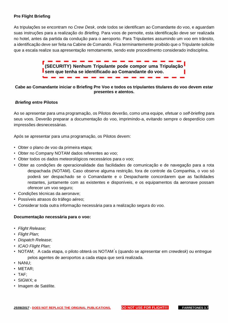
25/08/2017 - DOES NOT REPLACE THE ORIGINAL PUBLICATIONS. DO NOT USE FOR FLIGHT!!! FARRETONES 3.7
Pre Flight Briefing
As tripulações se encontram no Crew Desk, onde todos se identificam ao Comandante do voo, e aguardam
suas instruções para a realização do Briefing. Para voos de pernoite, esta identificação deve ser realizada
no hotel, antes da partida da condução para o aeroporto. Para Tripulantes assumindo um voo em trânsito,
a identificação deve ser feita na Cabine de Comando. Fica terminantemente proibido que o Tripulante solicite
que a escala realize sua apresentação remotamente, sendo este procedimento considerado indisciplina.
Cabe ao Comandante iniciar o Briefing Pre Voo e todos os tripulantes titulares do voo devem estar
presentes e atentos.
Briefing entre Pilotos
Ao se apresentar para uma programação, os Pilotos deverão, como uma equipe, efetuar o self-briefing para
seus voos. Deverão preparar a documentação do voo, imprimindo-a, evitando sempre o desperdício com
impressões desnecessárias.
Após se apresentar para uma programação, os Pilotos devem:
• Obter o plano de voo da primeira etapa;
• Obter no Company NOTAM dados referentes ao voo;
• Obter todos os dados meteorológicos necessários para o voo;
• Obter as condições de operacionalidade das facilidades de comunicação e de navegação para a rota
despachada (NOTAM). Caso observe alguma restrição, fora de controle da Companhia, o voo só
poderá ser despachado se o Comandante e o Despachante concordarem que as facilidades
restantes, juntamente com as existentes e disponíveis, e os equipamentos da aeronave possam
oferecer um voo seguro;
• Condições técnicas da aeronave;
• Possíveis atrasos do tráfego aéreo;
• Considerar toda outra informação necessária para a realização segura do voo.
Documentação necessária para o voo:
• Flight Release;
• Flight Plan;
• Dispatch Release;
• ICAO Flight Plan;
• NOTAM; A cada etapa, o piloto obterá os NOTAM ́s (quando se apresentar em crewdesk) ou entregue
pelos agentes de aeroportos a cada etapa que será realizada.
• NANU;
• METAR;
• TAF;
• SIGWX; e
• Imagem de Satélite.
(SECURITY) Nenhum Tripulante pode compor uma Tripulação
sem que tenha se identificado ao Comandante do voo.

25/08/2017 - DOES NOT REPLACE THE ORIGINAL PUBLICATIONS. DO NOT USE FOR FLIGHT!!! FARRETONES 3.7
Briefing com a Tripulação de Cabine
Geral – permite que a Tripulação discuta fatores específicos que poderão afetar o voo;
Quem – Comandante;
Quando – início do voo ou troca de Tripulação de cabine.
✓ Condições de tempo, turbulência, tempo de voo, situação de Manutenção da aeronave (MEL);
✓ Verificação da Tripulação (porte/validade de documentos);
✓ Determinação dos meios para que a Tripulação de Cabine possa notificar discretamente a
Tripulação Técnica quando houver suspeita ou violação da segurança na cabine;
✓ Revisão de procedimentos, se necessário.
Capacidade Física e Psíquica dos Tripulantes
Os Tripulantes devem estar gozando de boas condições físicas e psíquicas para compor Tripulação.
É proibido ser escalado, se apresentar e continuar uma programação se sua capacidade de saúde estiver
diminuída por:
• Gravidez;
• Doação de sangue – Não voar em um intervalo de 24 horas após a doação de sangue. Caso seja
necessário efetuar uma programação de voo antes de 24 horas após a doação, entrar em contato
com o Serviço Médico da Empresa para autorização;
• Mergulho Autônomo - Nunca voar dentro de 24 horas após a utilização de ar comprimido, nitrox, ou
misturas similares e evite voar por 12 horas se a profundidade tiver sido inferior a de 30ft. Mergulho
em apneia não requer interrupção para voo;
• Enfermidades;
• Traumatismos;
• Pós-operatório;
• Baixa condição física ou mental;
• Fadiga; ou
• Ingestão de medicamentos, álcool, drogas que afetem a capacidade de atenção ou os reflexos.
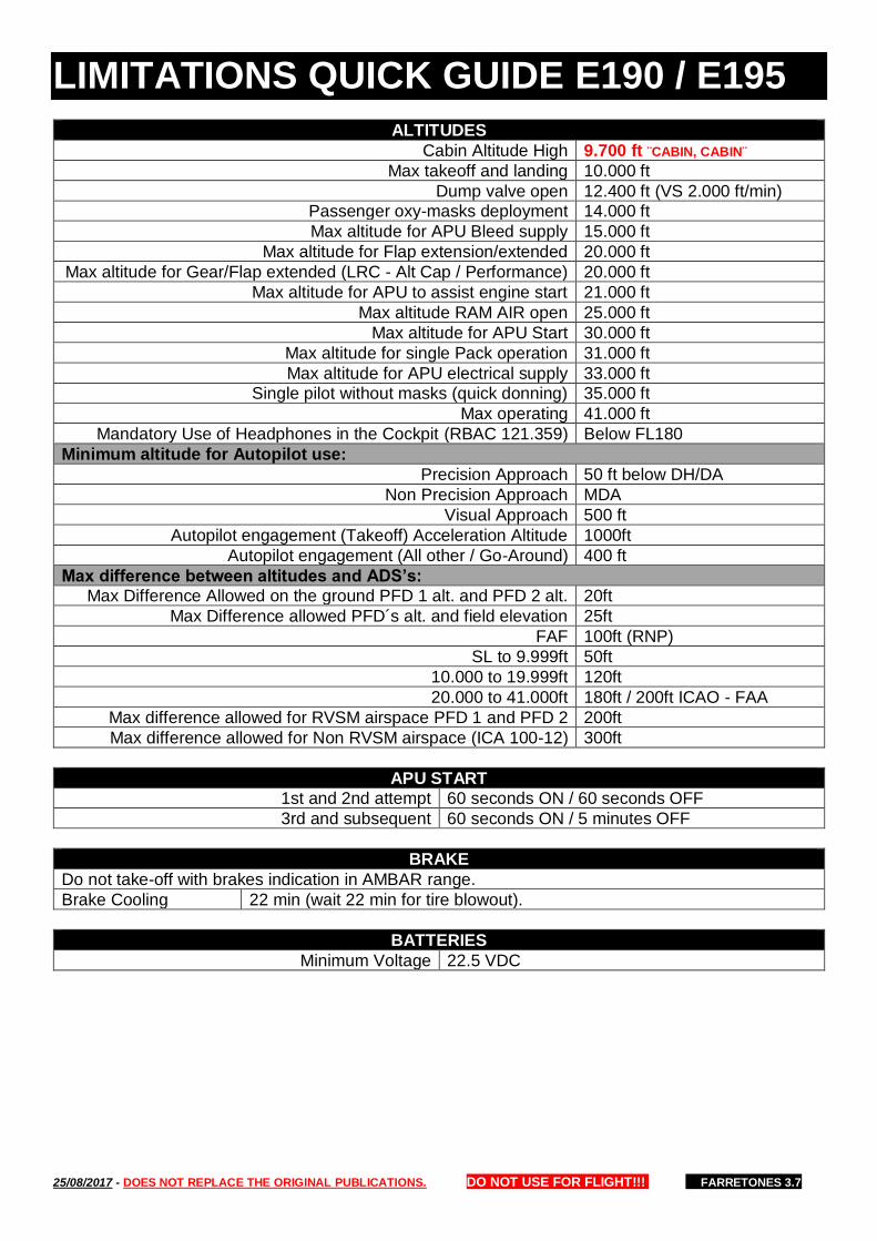
25/08/2017 - DOES NOT REPLACE THE ORIGINAL PUBLICATIONS. DO NOT USE FOR FLIGHT!!! FARRETONES 3.7
LIMITATIONS QUICK GUIDE E190 / E195
ALTITUDES
Cabin Altitude High 9.700 ft ¨CABIN, CABIN¨
Max takeoff and landing 10.000 ft
Dump valve open 12.400 ft (VS 2.000 ft/min)
Passenger oxy-masks deployment 14.000 ft
Max altitude for APU Bleed supply 15.000 ft
Max altitude for Flap extension/extended 20.000 ft
Max altitude for Gear/Flap extended (LRC - Alt Cap / Performance) 20.000 ft
Max altitude for APU to assist engine start 21.000 ft
Max altitude RAM AIR open 25.000 ft
Max altitude for APU Start 30.000 ft
Max altitude for single Pack operation 31.000 ft
Max altitude for APU electrical supply 33.000 ft
Single pilot without masks (quick donning) 35.000 ft
Max operating 41.000 ft
Mandatory Use of Headphones in the Cockpit (RBAC 121.359) Below FL180
Minimum altitude for Autopilot use:
Precision Approach 50 ft below DH/DA
Non Precision Approach MDA
Visual Approach 500 ft
Autopilot engagement (Takeoff) Acceleration Altitude 1000ft
Autopilot engagement (All other / Go-Around) 400 ft
Max difference between altitudes and ADS’s:
Max Difference Allowed on the ground PFD 1 alt. and PFD 2 alt. 20ft
Max Difference allowed PFD´s alt. and field elevation 25ft
FAF 100ft (RNP)
SL to 9.999ft 50ft
10.000 to 19.999ft 120ft
20.000 to 41.000ft 180ft / 200ft ICAO - FAA
Max difference allowed for RVSM airspace PFD 1 and PFD 2 200ft
Max difference allowed for Non RVSM airspace (ICA 100-12) 300ft
APU START
1st and 2nd attempt 60 seconds ON / 60 seconds OFF
3rd and subsequent 60 seconds ON / 5 minutes OFF
BRAKE
Do not take-off with brakes indication in AMBAR range.
Brake Cooling 22 min (wait 22 min for tire blowout).
BATTERIES
Minimum Voltage 22.5 VDC
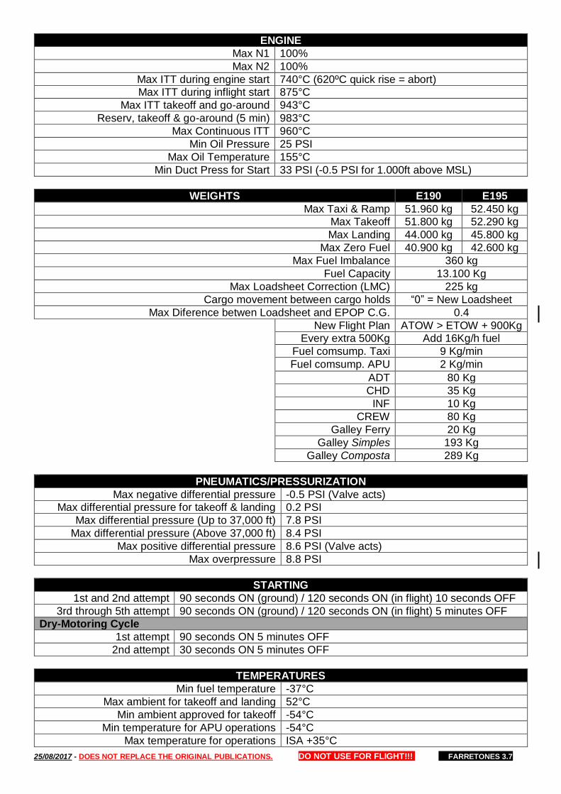
25/08/2017 - DOES NOT REPLACE THE ORIGINAL PUBLICATIONS. DO NOT USE FOR FLIGHT!!! FARRETONES 3.7
ENGINE
Max N1 100%
Max N2 100%
Max ITT during engine start 740°C (620ºC quick rise = abort)
Max ITT during inflight start 875°C
Max ITT takeoff and go-around 943°C
Reserv, takeoff & go-around (5 min) 983°C
Max Continuous ITT 960°C
Min Oil Pressure 25 PSI
Max Oil Temperature 155°C
Min Duct Press for Start 33 PSI (-0.5 PSI for 1.000ft above MSL)
WEIGHTS E190 E195
Max Taxi & Ramp 51.960 kg 52.450 kg
Max Takeoff 51.800 kg 52.290 kg
Max Landing 44.000 kg 45.800 kg
Max Zero Fuel 40.900 kg 42.600 kg
Max Fuel Imbalance 360 kg
Fuel Capacity 13.100 Kg
Max Loadsheet Correction (LMC) 225 kg
Cargo movement between cargo holds “0” = New Loadsheet
Max Diference betwen Loadsheet and EPOP C.G. 0.4
New Flight Plan ATOW > ETOW + 900Kg
Every extra 500Kg Add 16Kg/h fuel
Fuel comsump. Taxi 9 Kg/min
Fuel comsump. APU 2 Kg/min
ADT 80 Kg
CHD 35 Kg
INF 10 Kg
CREW 80 Kg
Galley Ferry 20 Kg
Galley Simples 193 Kg
Galley Composta 289 Kg
PNEUMATICS/PRESSURIZATION
Max negative differential pressure -0.5 PSI (Valve acts)
Max differential pressure for takeoff & landing 0.2 PSI
Max differential pressure (Up to 37,000 ft) 7.8 PSI
Max differential pressure (Above 37,000 ft) 8.4 PSI
Max positive differential pressure 8.6 PSI (Valve acts)
Max overpressure 8.8 PSI
STARTING
1st and 2nd attempt 90 seconds ON (ground) / 120 seconds ON (in flight) 10 seconds OFF
3rd through 5th attempt 90 seconds ON (ground) / 120 seconds ON (in flight) 5 minutes OFF
Dry-Motoring Cycle
1st attempt 90 seconds ON 5 minutes OFF
2nd attempt 30 seconds ON 5 minutes OFF
TEMPERATURES
Min fuel temperature -37°C
Max ambient for takeoff and landing 52°C
Min ambient approved for takeoff -54°C
Min temperature for APU operations -54°C
Max temperature for operations ISA +35°C

25/08/2017 - DOES NOT REPLACE THE ORIGINAL PUBLICATIONS. DO NOT USE FOR FLIGHT!!! FARRETONES 3.7
SPEEDS
Max operating airspeed VMO (300 kt below 8,000 ft)
Max operating airspeed VMO (320 kt 10.000 ft / 29.000 ft)
Max operating Mach number 0.82 (MMO)
Max airspeed for RAT operation VMO/MMO
Min airspeed for RAT operation 130 kt (QRH)
Turbulent Airspeed 270 kt/ 0.76 (250 Kt below FL100)
Max windshield wiper operation speed 250 kt
Max speed with windshield wiper failed in non-parked position 320 kt
Tire limit ground speed 195 kt
Max gear extension speed VLO 265 kt
Max gear retraction speed VLO 235 kt
Max speed Flap position 1 230 kt
Max speed Flap position 2 215 kt
Max speed Flap position 3 200 kt
Max speed Flap position 4 and 5 180 kt
Max speed Flap position FULL 165 kt
Design maneuvering speed 240 kt
Maximum speed to open the Direct Vision Window 160 kt
Max Taxi Speed (Straight ahead) 30 Kt
Max Taxi Speed on High Speed Taxiway 60 Kt (Dry) 30 Kt (Wet)
Normal Taxi Speed (Straight ahead) 20 Kt (Dry) 10 Kt (Wet)
Max Taxi Speed (Turns & Aprons) 10 Kt (Dry) 5 Kt (Wet)
FMS SPD + 15nm landing AD
WIND
CAT II – HUD A3 25 kt headwind e 15kt crosswind
LVTO 25kt headwind, 15kt crosswind, 5kt tailwind
Max 90º crosswind component (STEADY)
(a) Takeoff and Landing 25 kt DRY RWY / SDU 15 kt DRY - 05 kt WET
(b) Takeoff 20 kt WET RWY
(c) Landing 15 kt WET RWY
(d) Takeoff and Landing 10 kt STANDING WATER GROOVED RWY
(e) Takeoff and Landing 05 kt STANDING WATER NON-GROOVED RWY
(f) Takeoff and Landing 15kt DRY RWY or TWY (1.700M x 40M or less)
(g) Takeoff and Landing 05kt WET RWY or TWY (1.700M x 40M or less)
Max takeoff and landing tailwind component 10 kt (05 Kt for SDU)
Maximum wind for passenger door operation 40 kt
Maximum wind for cargo door opening 40 kt
CALCULATION
ALT for short trips 10% distance + 5 (eg. 230nm = 23+5 = FL280)
MACH change 0.01 MACH = 6 KTAS
ERJ190 Gross Fuel Planning 37 Kg/min
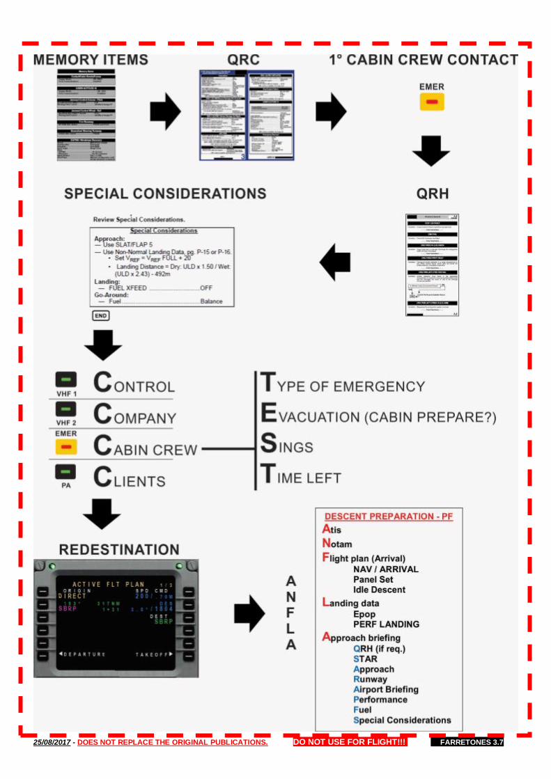
25/08/2017 - DOES NOT REPLACE THE ORIGINAL PUBLICATIONS. DO NOT USE FOR FLIGHT!!! FARRETONES 3.7

25/08/2017 - DOES NOT REPLACE THE ORIGINAL PUBLICATIONS. DO NOT USE FOR FLIGHT!!! FARRETONES 3.7
Weather Deviation – No ATC Comm DOC4444 15.2.3 ID, FL, position, intentions …………………. 121.50 & 123.45
Watch for traffic & routes …………………... Visually + ACAS Exterior lights ……………………………………………. All ON
Deviation less than 10NM …………………. Maintain ATC FL
Deviation more than 10NM ……............... At 10NM off AYW: Route Track Deviation FL Change
000° – 179° LEFT DES ß 300ft
RIGHT CLB Ý 300ft
180° – 359° LEFT CLB Ý 300ft
RIGHT DES ß 300ft
SLOP – Strategic Lateral Offset DOC4444 16.5.2
Lateral Separation AYW ³ 30NM Max 2 NM Right
Lateral Separation AYW ³ 6 NM Max 0.5 NM Right
- SLOP only if Airspace Offsets Authorized by ATS Authority
- Automatic FMS Offset Capability (Crew Decision to Offset)
- Coordinate Offset in 123.45 (Not Required to Advise ATC)
Emergency Descent DOC4444 15.1.4 Navigation ………………..…….… As appropriate by the pilot
ATC ………… Advise the emergency descent and intentions
Transponder ……………..…… Code 7700 / EMER ADS-B/C Exterior lights ………………..………………………..… All ON
Watch for traffic & routes …………………... Visually + ACAS When emergency descent is complete, coordinate
further intentions with the appropriate ATS unit.
Holding Speeds Tables ATC - DOC8168 - HOLDING LEVEL NORMAL TURBULENCE
Tab
le IV
-1-1
ICA
O 0 – 14.000 ft 230 KT 280 KT
14.001 – 20.000 ft 240 KT 280 KT or MACH 0.80 20.001 – 34.000 ft 265 KT
Above 34.001 ft MACH 0.83 MACH 0.83
LEVEL PROP JET
Tab
le IV
-1-2
PA
NS
OP
S
NORMAL TURBULENCE
0 – 6.000 ft 170 KT 210 KT 280 KT or
MACH 0.80 6.001 – 14.000 ft 170 KT 220 KT
Above 14.001 ft 175 KT 240 KT
LEVEL ALL AIRCRAFT
Tab
le
IV-1
-3
FA
A
At or Below 14.000 ft
01:00 Leg Above 14.000 ft
01:30 Leg
0 – 6.000 ft 200 KT
6.001 – 14.000 ft 230 KT
Above 14.001 ft 265 KT
Do not use for flight! V 1.0 06.07.2017 By L. F. Farret
Checklist – International Flight
JEPPESEN AIRWAY MANUAL PREFACE AIRAC Calendar Jeppesen Actualization
CHART CHANGE NOTICES Route (FIR) NOTAMs Airport (Terminal) NOTAMs
ENROUTE Transponder SSR METEOROLOGY VOLMETs ATC – STATES RULES & PROCEDURES States Differences
Holding Speeds IFR Procedures (Pans Ops or TERPS)
EMERGENCY Communication Failure
ICAO / States Emergency
ATC CONTINGENCIES - DOC 4444 CHAPTER 15 Depressurization, Emergency Descent, Weather Deviation
ICAO Communication Failure DOC4444 15.3.3
No Radar: Maintain last assigned SPD & FL, or Min Flight
ALT, for 20 min, then adjust SPD / FL iaw Filed Flight Plan… Radar: Maintain last assigned SPD & FL, or Min Flight ALT,
for 7 min, then adjust SPD / FL iaw Filed Flight Plan… Vector/Offset (No limit): Rejoin Flight Plan Route no later
than the next significant point, observe Min Flight ALT…
… Proceed according to flight plan route to the navigation aid/fix serving the aerodrome, hold until start of descent as
close as possible to, the expected approach time last received
or the current flight plan ETA; Complete the approach procedure for the aid/fix; Land within 30 min after the ETA or
the expected approach time, whichever is later.
HF Frequency Propagation ENROUTE – GENERAL
3 494 8 930 11 345 13 342 17 916 23 210
Night Day & Night Day