eriks simering
DESCRIPTION
sealTRANSCRIPT

O I L S E A L S
�
Oil Seals
Seal
ing
Elem
ents

O I L S E A L S
�
Con t en t s
ERIKS OIL SEALS TECHNICAL MANUAL�. Introduction�. DescriptionandprincipleofOilSeals3. ConstructionofOilSeals4. Commontypes5. Commonmaterials6. Shaftmaterials,sealtoleranceandhousing7. Shafteccentricityandshaftrunout8. Materialsandtolerancesoftheshaft9. Lubrication�0. OilSealsforhigherpressures��. SplitOilSeals��. AssemblyoftheOilSeal�3. Troubleshooting�4. Conversiontableinch/mm�5. TableofDINdimensions

O I L S E A L S
3
1. I n t r od uc t i on
ERIKSisknownworldwideforitscomprehensiverangeofsealsincludingO-rings,rotaryshaftseals,hydraulicandpumpseals.
Since�960,ERIKShavedevelopedthisrangetoincludethefollowingproductlines:
NBROilSealsinallstandardtypesandsizesVitonOilSealstypeGRandGRST,fullyencapsulatedOilSealsofrubber/textileconstructionforheavydutyapplicationsOilSealsinnonstandardrubbercompoundssuchasEPDM,XNBR,HNBR,Silicone,etc...ERIKSPTFElipsealsandPSSealsOilSealsforhigherpressures:VROilSealsEndcapsV-sealsAlphaseals
InthisdocumentationyouwillfindthemostrelevanttechnicalinformationregardingOilSeals.
ERIKShas9000mouldstoproducethesestandardOilSealsaswellastheproductionfacilitiestoproducesmallquantitiesofnonstandardOilSeals.
Wewillbepleasedtogiveyoutheinformationyouneed.Youwillbesurprisedbyourkeenprices!
•••
•
•••••

O I L S E A L S
4
2 . P r i nc i p l e o f O i l S ea l s
Oil Seals
OneofthemostfrequentlyusedtypesofsealistheRotaryShaftSeal.Thisisgenerallyusedforsealinglubricatingoilorgreaseinrotaryshaftapplications.Inexceptionalcases,itisalsousedtosealotherfluids,gasesandpowderedorgranularsolids.Fortrouble-freeoperationandoptimumservicelifeofaseal,shaftsmusthaveasatisfactorysurfacefinish,withinrecommendedlimitsandhavenomachinelay.Bothcorrectdesignandmaterialchoicearecriticalifbearingsandgearsaretobesealedtopreventtheleakageoflubricatingoilsandgreasesandtheingressofpenetratingdustanddirt.
SealingAgoodlubricatingoilformsastrongtenaciousfilmongears,bearingsandshaftsandisnoteasilyremovedfromthepressurebearingsurfacesofthese.However,wheretheshaftextendsawayfromtheequipment,thisoilfilmmustberetained.InOilSeals,thepressureorradialloadexertedbythesealinglipmustbesufficienttoretaintheoilfilm,whilstnotsohighthatexcessivefrictionlossesorwearcanoccur.GoodOilSealdesignisthereforeabalancebetweenoptimumrunningpropertiesofthematerial,lipdesignandintegralgarterspring.
Working principleDuringrotationoftheshaft,ahydrodynamicfilmoflubricantisproducedbeneaththesealinglip,thethicknessofwhichdependsonshaftspeed,oiltemperature,oilviscosityandthepressureorradialloadexertedbythesealinglipontheshaft.Duetocapillaryforcesandthesurfacetopographyoftheshaft,thefluidbeingsealedformsameniscusunderthesealinglipandispreventedfromleaking.Thefluid,thesealmaterial,thefilmthickness,thesealinglipgeometryandthesurfacetopographyoftheshaftaregoverningfactorsintherealisationofthesecapillaryforces.Ausedsealhavingashinywearflatwithhardeningandradialcrackingisindicativethatithadoperatedonashaftwhichwastoosmoothand/orthattheradialloadexertedbythelipwastoohigh.Ausedsealhavingawidewearflatisindicativethatithadoperatedonashaftwhichwastoorough,especiallyiftherewasnohardeningorradialcrackingandcouldalsobeassociatedwithincorrectsealinglipgeometry.
outsideinsideoil air

O I L S E A L S
5
3 . Cons t r uc t i on o f t he o i l sea l
DIN 3760/3761
DIN3760/376�describesthestandardisationofdesign,dimensionsandtolerancesofOilSeals.
DINStandard3760 ERIKSTYPE
A RUBBERCOVERED R
AS ASTYPEAWITHDUSTLIP RST
B METALCASEDDESIGN M
BS ASTYPEBWITHDUSTLIP MST
C DOUBLEMETALCASED GV
CS ASTYPECWITHDUSTLIP GVST
TYPE RThemostcommonlyusedtypeistypeR.Thistypehasacarbonsteelinsertandhasrubberoutsidediameter.Therubbergivesagoodsealingcapability,evenwhenthehousingisnotfullyintolerance.Thesealinglipwithspringprovidesinterferenceontheshaftforeffectivesealing.Theoutsidediameter,withinnermetalreinforcementcase,allowspress-fittinginthehousing,withsufficientinterferenceontherubbertoprovidestaticsealing.ThesealingelementisproducedfromahighperformanceNitrilerubber.ThisincombinationwithahighqualitygalvanisedsteelgarterspringgivestheERIKSOilSealanoptimumlife.Inordertopreventleakagesduetoahydrodynamicpumpingeffectisitnecessarythatthesealinglipcontactareaonthesleeveorshaftiswithoutanytracesofmachinelay.
Metal componentsDependingontheapplication,ERIKSOilSealsaresuppliedwithvarioustypesofmetal.
The reinforcing caseCarbonsteelasstandardbutstainlesssteelorbrassondemand.
TYPE GR
Thistypeisfullycoveredwithrubberontheinsideofthereinforcingcase.ERIKSGRViton®OilSealsareofthistypeandarefittedwithastainlesssteelgarterspring.ThistypecanalsobesuppliedinNitrilerubberondemand.
The garter springGalvanisedsteelasstandard.Stainlesssteel,bronzeoranelastomercanbesuppliedondemand.
outsidesurface
metalinsert
backabutmentface
dustlip
flexsection
moldedface
sealwidth(orrange)
frontchamfer
lining
garterspring
springgroove
trimface
sealingedge
outside inside

O I L S E A L S
�
Part 1: Construction with outside rubber diameter
4 . Com mon t y pes
ERIKS type Description
Type RZVSmaller sizes only for applications such as needle bearings and grease seal.
Type RGZVSimilar application as type RZV, but the outside surface has a ribbed design.
Type RRubber outer diameter with a carbon steel insert. Construction is in ac-cordance with DIN 3760A and available in both metric and inch sizes.
Type R-RVS Oil Seal with a RVS-304 spring
Type R-O RING Oil Seal with a rubber spring
Type RGRibbed outer rubber surface. With this system the thermal expansion of the housing is absorbed. This is used in automotive applications.
TYPE RSTOil Seal with additional dust lip to prevent damage of sealing lip and to avoid the ingress of dust, dirt, water etc. into the system. Very com-monly used in both metric and inch sizes.
Type RGSTIdentical application as type RST, but the outside rubber surface has a ribbed design to absorb thermal expansion of the housing.
Type RST-DSeals pressures to 10 bar (1MPa) depending on the circumstances because it is more compact than type RST. It is recommended that our application engineers should be contacted.
Type RV
The helical spring is encapsulated in the seal. This is important when the seal has to be moved over almost the full shaft length, preventing both dislodgement of the spring and its contact with the medium to be sealed.
O I L S E A L S
7
ERIKS type Description
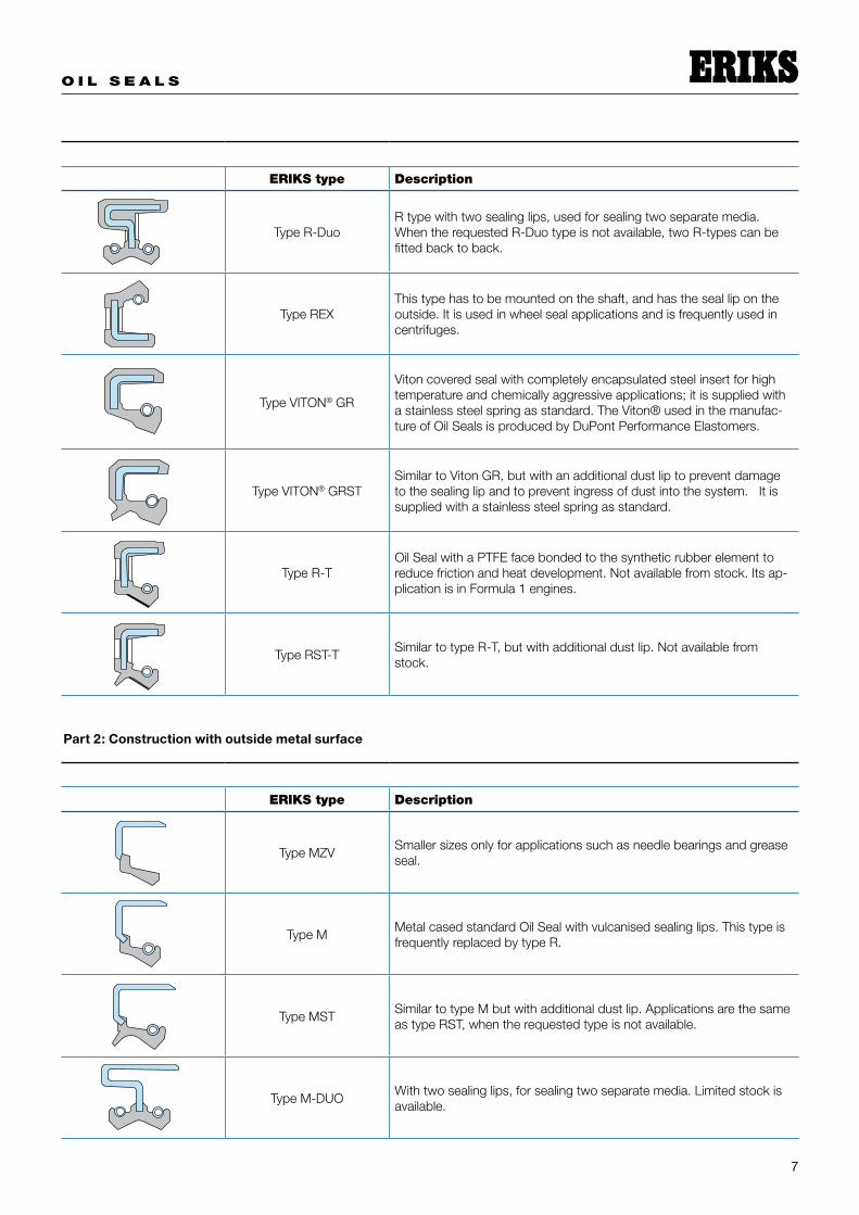
Type R-DuoR type with two sealing lips, used for sealing two separate media. When the requested R-Duo type is not available, two R-types can be fitted back to back.
Type REXThis type has to be mounted on the shaft, and has the seal lip on the outside. It is used in wheel seal applications and is frequently used in centrifuges.
Type VITON® GR
Viton covered seal with completely encapsulated steel insert for high temperature and chemically aggressive applications; it is supplied with a stainless steel spring as standard. The Viton® used in the manufac-ture of Oil Seals is produced by DuPont Performance Elastomers.
Type VITON® GRSTSimilar to Viton GR, but with an additional dust lip to prevent damage to the sealing lip and to prevent ingress of dust into the system. It is supplied with a stainless steel spring as standard.
Type R-TOil Seal with a PTFE face bonded to the synthetic rubber element to reduce friction and heat development. Not available from stock. Its ap-plication is in Formula 1 engines.
Type RST-TSimilar to type R-T, but with additional dust lip. Not available from stock.
Part 2: Construction with outside metal surface
ERIKS type Description
Type MZVSmaller sizes only for applications such as needle bearings and grease seal.
Type MMetal cased standard Oil Seal with vulcanised sealing lips. This type is frequently replaced by type R.
Type MSTSimilar to type M but with additional dust lip. Applications are the same as type RST, when the requested type is not available.
Type M-DUOWith two sealing lips, for sealing two separate media. Limited stock is available.
O I L S E A L S
8
ERIKS type Description
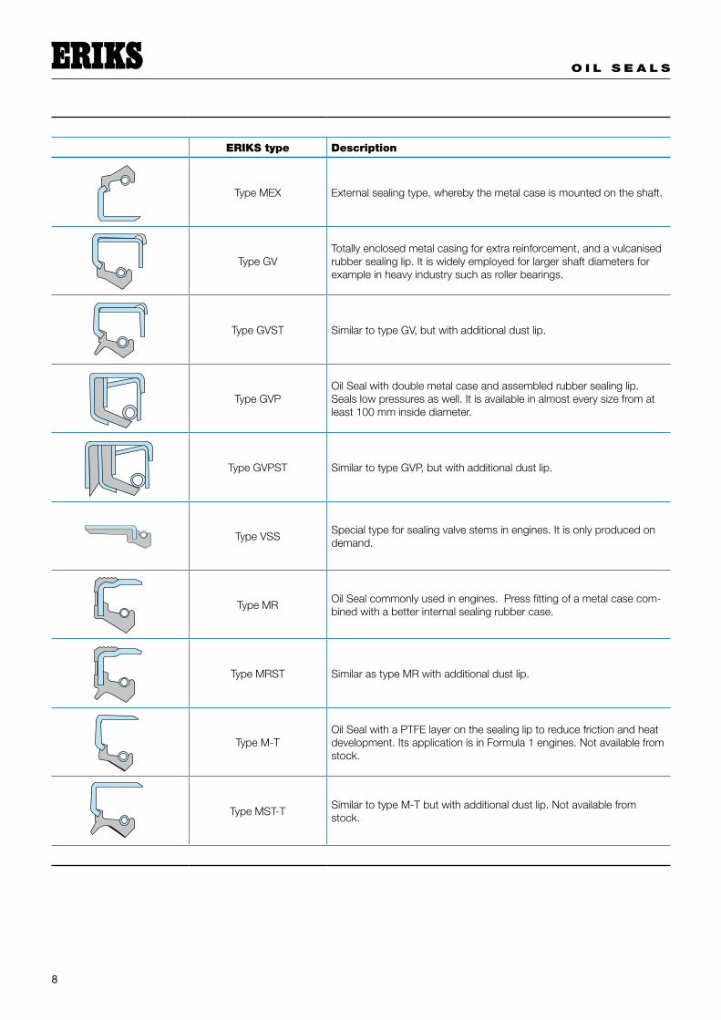
Type MEX External sealing type, whereby the metal case is mounted on the shaft.
Type GVTotally enclosed metal casing for extra reinforcement, and a vulcanised rubber sealing lip. It is widely employed for larger shaft diameters for example in heavy industry such as roller bearings.
Type GVST Similar to type GV, but with additional dust lip.
Type GVPOil Seal with double metal case and assembled rubber sealing lip. Seals low pressures as well. It is available in almost every size from at least 100 mm inside diameter.
Type GVPST Similar to type GVP, but with additional dust lip.
Type VSSSpecial type for sealing valve stems in engines. It is only produced on demand.
Type MROil Seal commonly used in engines. Press fitting of a metal case com-bined with a better internal sealing rubber case.
Type MRST Similar as type MR with additional dust lip.
Type M-TOil Seal with a PTFE layer on the sealing lip to reduce friction and heat development. Its application is in Formula 1 engines. Not available from stock.
Type MST-TSimilar to type M-T but with additional dust lip. Not available from stock.

O I L S E A L S
9
Part 3: Construction with fabric insert reinforcement
ERIKS type Description
Type WR35Outside surface with fabric insert reinforcement. Oil Seal without metal reinforcement. Split Seals also available. These are frequently installed back to back with a lock-in plate. They are available in NBR and FPM.
Type WR36Similar to type WR35, but additional grooves on the back side for optimal grease supply to the sealing lips when back-to-back mounted.
Type WR37 Similar to type WR36, with grooves on the whole contour.
Part 4: Split construction “Split Seals”
ERIKS type Description
WR35 SplitSimilar to type WR35, but in split construction. Commonly used when dismantling is time consuming, for example roller bearings in the steel and paper industry, or marine propeller shafts.
WR36 Split Similar to type WR36, but in split construction.
WR37 Split Similar to type WR37, but in split construction.
23 SplitFull rubber construction as standard type Oil Seal, with a helical spring. These are only available in a limited number of sizes.

O I L S E A L S
�0
Part 5: diverse products
ERIKS type Description
PTFE Lip sealStainless steel outer casing and modified PTFE lip. Applicable for up to 10 bar (1MPa)
Dyna Lip sealMade from modified PTFE without metal parts. These can be supplied with or without a Viton® O-ring on the outside diameter. Always assemble with lock-in plate.
Combi SealA seal developed for extreme wear applications. The Oil Seal and dust seal are combined in one metal case, ready for use.
Cassette SealMultilip construction with sleeve. Used as wheel seals in excavator applications.
End capEnd cap is used to seal holes (in for example gear boxes). Assemble by press fitting, as Oil Seal with a rubber case.
ErisleeveHard chromed stainless steel sleeves to use on worn shafts. They are available in almost every shaft diameter from ½” to 8”.

O I L S E A L S
��
5 . Com mon M a t e r i a l s
Inthestandardconstruction,ourOilSealsaremadefromoilandgreaseresistantrubberbasedonNBR(Perbunan).
Thismaterialhasverygoodrunningpropertiesandexcellentwearresistance.Forhighshaftspeeds,largeradialtolerancesandgoodchemicalresistancearangeofotherrubbermaterialsisavailable.
Choice of material for Oil Seal
Rubber Type Material Code ISO 1629 Heat resistance
Nitrile
NBR -35°C tot + 100°CHigh wear resistance good running properties for general use
Polyacrylate
ACM -20°C tot + 130°CBetter heat, oil and chemical resistance than NBR
It is recommended for use in oil which contains load bearing additives such as EP gear oils
Viton®
FPM -30°C tot + 180°CHigh level of chemical resistance
High temperature resistance
Silicone
MVQ -50°C tot + 150°CWide temperature range
Commonly used in low temperature applications
Very prone to mechanical damage during fitting
Polytetrafluoroethylene
PTFE -80°C tot + 200°CChemical resistant
Low coefficient of friction poor elastic properties not wear resistant if used by dynamic applications
Leather
-40°C tot + 90°C
Recommended for abrasive applications.
Good running properties, due to the impregnated seal lip.
Can be used on shafts which have a surface roughness outside the range for rubber Seals
Not suitable for water.
O I L S E A L S
��
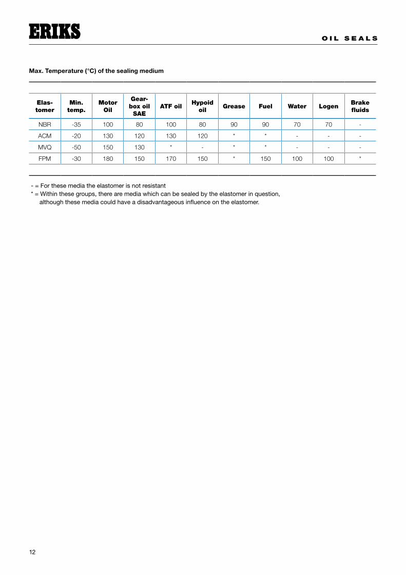
Max. Temperature (°C) of the sealing medium
Elas-tomer
Min. temp.
Motor Oil
Gear-box oil SAE
ATF oilHypoid
oilGrease Fuel Water Logen
Brake fluids
NBR -35 100 80 100 80 90 90 70 70 -
ACM -20 130 120 130 120 * * - - -
MVQ -50 150 130 * - * * - - -
FPM -30 180 150 170 150 * 150 100 100 *
-=Forthesemediatheelastomerisnotresistant*=Withinthesegroups,therearemediawhichcanbesealedbytheelastomerinquestion,althoughthesemediacouldhaveadisadvantageousinfluenceontheelastomer.
O I L S E A L S
�3
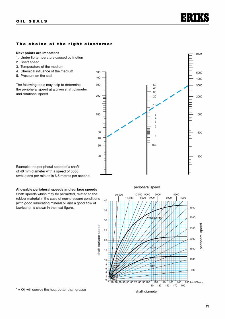
The cho ice o f t he r i g h t e l a s t omer
Next points are important�. Underliptemperaturecausedbyfriction�. Shaftspeed3. Temperatureofthemedium4. Chemicalinfluenceofthemedium5. Pressureontheseal
Thefollowingtablemayhelptodeterminetheperipheralspeedatagivenshaftdiameterandrotationalspeed
Example:theperipheralspeedofashaftof40mmdiameterwithaspeedof3000revolutionsperminuteis6.5metrespersecond.
Allowable peripheral speeds and surface speedsShaftspeedswhichmaybepermitted,relatedtotherubbermaterialinthecaseofnon-pressureconditions(withgoodlubricatingmineraloilandagoodflowoflubricant),isshowninthenextfigure.
*=Oilwillconveytheheatbetterthangrease
peripheralspeed
per
iphe
rals
pee
d
shaf
tsu
rfac
esp
eed
shaftdiameter
O I L S E A L S
�4
6 . S h a f t m a t e r i a l s , t o l e r a nces o f sea l s a nd hou s i n g
The housing of the Oil Seal
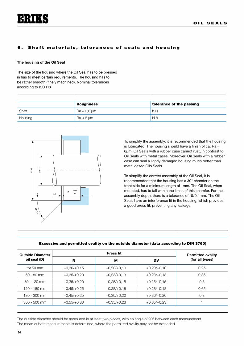
ThesizeofthehousingwheretheOilSealhastobepressedinhastomeetcertainrequirements.Thehousinghastoberathersmooth(finelymachined).NominaltolerancesaccordingtoISOH8
Tosimplifytheassembly,itisrecommendedthatthehousingislubricated.Thehousingshouldhaveafinishofca.Ra=6µm.OilSealswitharubbercasecannotrust,incontrasttoOilSealswithmetalcases.Moreover,OilSealswitharubbercasecansealalightlydamagedhousingmuchbetterthanmetalcasedOilsSeals.
TosimplifythecorrectassemblyoftheOilSeal,itisrecommendedthatthehousinghasa30°chamferonthefrontsideforaminimumlengthof�mm.TheOilSeal,whenmounted,hastofallwithinthelimitsofthischamfer.Fortheassemblydepth,thereisatoleranceof-0/0,4mm.TheOilSealshaveaninterferencefitinthehousing,whichprovidesagoodpressfit,preventinganyleakage.
Roughness tolerance of the passing
Shaft Ra ≤ 0,6 μm h11
Housing Ra ≤ 6 μm H 8
Excessive and permitted ovality on the outside diameter (data according to DIN 3760)
Outside Diameter oil seal (D)
Press fit Permitted ovality (for all types)R M GV
tot 50 mm +0,30/+0,15 +0,20/+0,10 +0,20/+0,10 0,25
50 - 80 mm +0,35/+0,20 +0,23/+0,13 +0,23/+0,13 0,35
80 - 120 mm +0,35/+0,20 +0,25/+0,15 +0,25/+0,15 0,5
120 - 180 mm +0,45/+0,25 +0,28/+0,18 +0,28/+0,18 0,65
180 - 300 mm +0,45/+0,25 +0,30/+0,20 +0,30/+0,20 0,8
300 - 500 mm +0,55/+0,30 +0,35/+0,23 +0,35/+0,23 1
The outside diameter should be measured in at least two places, with an angle of 90° between each measurement. The mean of both measurements is determined, where the permitted ovality may not be exceeded.

O I L S E A L S
�5
7. Eccen t r i c i t y a nd s h a f t o sc i l l a t i on
Eccentricity
Itisobviousthatthecentrelinesofthehousing,OilSealandshafthavetocoincideasmuchaspossible.ThesealingelementoftheOilSealwillonlytolerateaminimumdeviation.ThemaximumpermittedeccentricityisdependentonthesizeoftheshaftandthetypeofOilSeal.Inthiscase,weassumestaticeccentricity,andnoshaftrunout.
ERIKShasspecialtypesofOilSeals,whicharesuitableforapplicationswithlargeshafteccentricityandrunout.Informationonallthepossibilitiesisavailable.
Shaft oscillation
Whenshaftrunoutispresent,sealswithaloosegarterspringarepreferredtosealswithanencapsulatedspring.Therunoutshouldremainwithinthelimits.“A”representsthedifferencebetweenthecentrelineofthehousingboreandthecentrelineoftheshaftintheregionofthesealline.Thetwocentrelinesdonotrunparallel.ThepermittedmaximumvalueofAdependsontherotationalspeed,thedimensionsoftheshaftandtheOilSeal.
shaftvelocity
MVQ
NBR,ACM,FPM
shaf
tec
cent
ricity
inm
m
shaftdiametertill500mm
shaf
tru
nout
(mm
)
Abovediagrammshowsthemaximumallowableexcentricity Abovediagrammshowsthemaximumallowableshaftrunout
centerlineshaft
centerlinebore
O I L S E A L S
�6
8 . S h a f t m a t e r i a l s a nd t o l e r a nces
Material
TherubbermaterialoftheOilSealismuchsofterthantheshaft,butduetofrictionbetweentheshaftandtheseal,itispossibleforweartooccuronthecontactsurfaceoftheshaft.Thedegreeofweardependsonthestructureoftheshaftmaterial.Ingeneral,themetalfromwhichtheshaftismadeshouldhaveahomogeneousfinegranulousstructureandmusthaveaminimumsurfacehardnessofHRc45.Ifthelubricationisdoubtful,themediumiscontaminated,dirtcanenterfromtheoutsideandthespeedoftheshaftismorethan4m/sec,thehardnessoftheshaftshouldbeaminimumofHRc55.Ingeneral,shaftsofcarbonsteelorstainlesssteelaremostsuitable.Surfacehardeningisrecommended.Inthecaseofhardchromedshafts,theuniformityofthechromeplatinghastomeetveryhighrequirements.Inpractice,suchsurfacesdonotmeettheseoptimumrequirements.Coatedshafts,forexamplewithchromeoxide(ceramics)havetobecarefullymachined.Thecoatingshouldnothaveporeslargerthan0,05mm.Thisisalsothecaseforthesurfaceofcastironwithaperliticstructure.Insomecases,non-ferrousmetalssuchasbrassMS58Hareused.CeramicsleevesandErisleevesareveryusefulastoo.Erisleevesareusedinbothoriginalequipmentassemblyandrepair.
Comment:Plasticsareunsuitableduetotheirpoorthermalconductivity.Becauseofthis,underlipheatgenerationcannotbereadilyconductedaway,whichisnotdesirable.
Requirements of the shaft
EvenmoreimportantthanacorrectinterferencefitoftheOilSealisaperfectlysmoothshaftintheregionoftheseal,particularlyifshaftsurfacespeedishighandthemediumtobesealedisunderacertainamountofexcesspressure.ThesurfaceroughnessoftheshaftdependsontheaverageprofiledepthRaofthetoolmarkscausedbythemachiningprocess.OilSealsmadeofPTFErequire,independentofthesurfacespeed,asurfaceroughnessofbetween0,�to0,�µm,becausePTFEhaslesswearresistancethanrubberseals.
Fornormalcircumstances,theshaftintheregionofthesealmusthaveasurfaceroughnessofapproximately:
Tosummarize,thesurfaceoftheshaftintheregionofthesealshouldnothavenoticeablemachiningmarks.Forpivotingshaftsandotherdifficultorcriticalsealingapplications,itisrecommendedthatOilSealswithahelicalgroovehydrodynamicpattern,whichhasapumpingeffect,beused.Whengrindingandpolishing,anaxialmovementofthegrindstonealongtheshaftmustbeavoidedinordertopreventmachinelay.
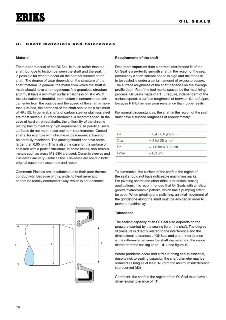
Tolerances
ThesealingcapacityofanOilSealalsodependsonthepressureexertedbythesealinglipontheshaft.ThedegreeofpressureisdirectlyrelatedtotheinterferenceandthedimensionaltolerancesofOilSealandshaft.Interferenceisthedifferencebetweentheshaftdiameterandtheinsidediameterofthesealinglip(d–d�),seefigure�0.
Whereproblemsoccurandafreerunningsealisessential,despiterisktosealingcapacity,theshaftdiametermaybereducedaslongasatleast�/3rdoftheminimuminterferenceispreserved(d�)
Comment:theshaftintheregionoftheOilSealmusthaveadimensionaltoleranceofh��.
Ra = 0,4 - 0,8 μm of -
CLa = 8 tot 25 μm of
Rz = 1,0 tot 4,0 μm en
Rmax ≤ 6,3 μm
�
O I L S E A L S
�7
9. Lu b r i ca t i on
Oilsealsforrotatingorreciprocatingshaftsrequireacertaindegreeoflubricationofthemovingsurfaces.
Oil Seals must never run dry
Whensealsareadjacenttobearings,thebearinglubricantwillgenerallyprovidesufficientlubricationfortheseal.Sealingwateraswell,mostofthetimethereisenoughlubrication.However,inisolatedlocationsorapplicationsinvolvingnon-lubricatingmedium,provisionshouldbemadeforlubricanttoreachtheseal.Insuchcase,dualsealsfrequentlyprovideananswerasthespacebetweenthesealingedgescanbepre-packedwithgreasethusallowingaconsiderableperiodofoperationwithoutfurtherattention.Insuchinstances,theOilSealsshouldbemountedinsuchawaythatnopressurebuild-upcanoccurwhenaddingthegrease.
Thepresenceoflubricationisimportant,notonlyduringoperation,butduringassemblyaswell.NeverassembleanOilSealdry.BoththeshaftandtheOilSealhavetobelubricatedwithoilorgreaseinadvance.Thiseasestheassemblyandensureslubricationfromthebeginning.
IfOilSealswithfixeddustlipsarebeingused,thespacebetweenthesealinglipandthedustlipmayalsobefilledentirelywithgrease.Themediumtobesealedwilldissipatetheheatdeveloped.
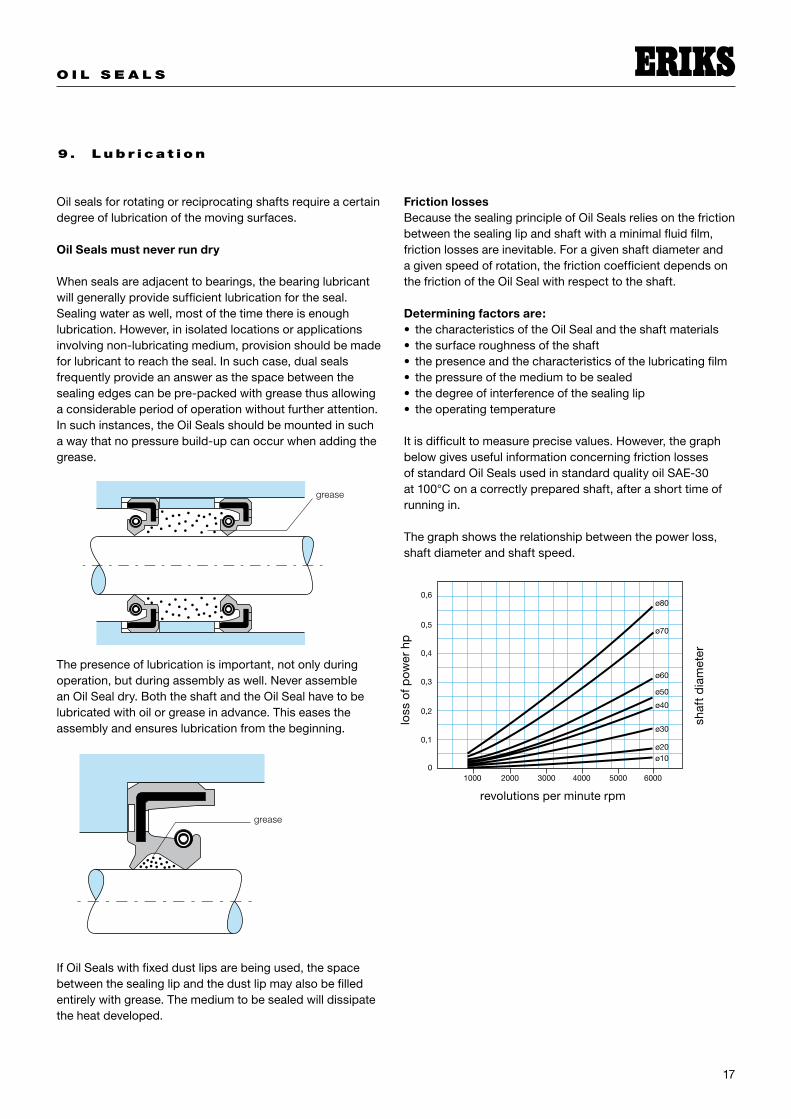
Friction lossesBecausethesealingprincipleofOilSealsreliesonthefrictionbetweenthesealinglipandshaftwithaminimalfluidfilm,frictionlossesareinevitable.Foragivenshaftdiameterandagivenspeedofrotation,thefrictioncoefficientdependsonthefrictionoftheOilSealwithrespecttotheshaft.
Determining factors are:thecharacteristicsoftheOilSealandtheshaftmaterialsthesurfaceroughnessoftheshaftthepresenceandthecharacteristicsofthelubricatingfilmthepressureofthemediumtobesealedthedegreeofinterferenceofthesealingliptheoperatingtemperature
Itisdifficulttomeasureprecisevalues.However,thegraphbelowgivesusefulinformationconcerningfrictionlossesofstandardOilSealsusedinstandardqualityoilSAE-30at�00°Conacorrectlypreparedshaft,afterashorttimeofrunningin.
Thegraphshowstherelationshipbetweenthepowerloss,shaftdiameterandshaftspeed.
••••••
grease
grease
shaf
td
iam
eter
revolutionsperminuterpm
loss
ofp
ower
hp
O I L S E A L S
�8
10 . O i l S ea l s f o r h i g he r p r es s u r es
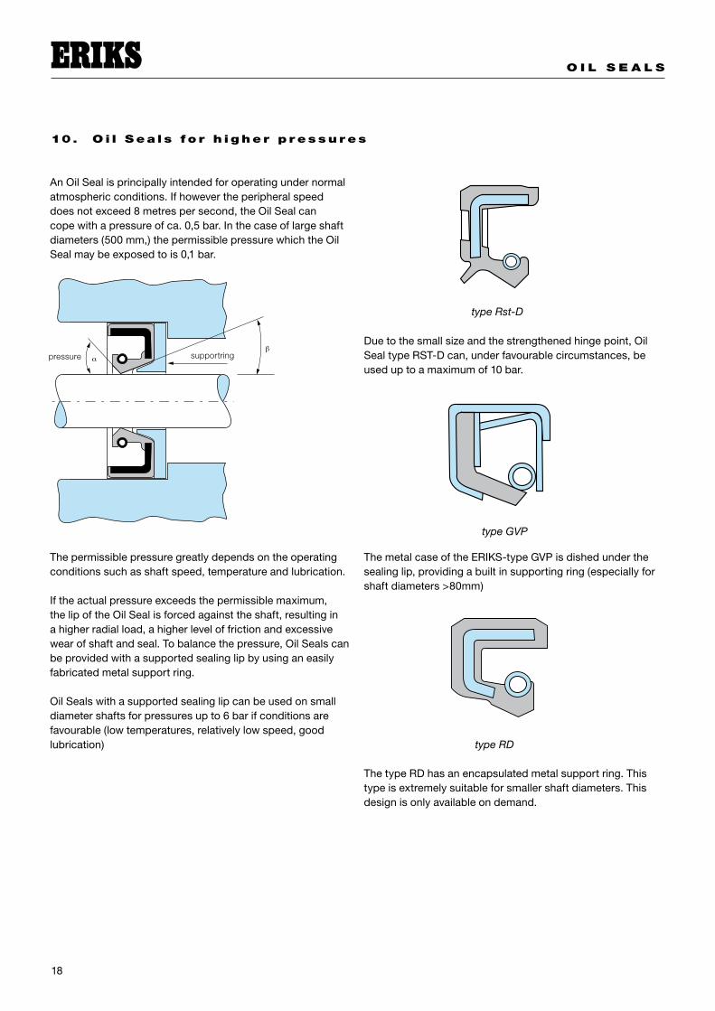
AnOilSealisprincipallyintendedforoperatingundernormalatmosphericconditions.Ifhowevertheperipheralspeeddoesnotexceed8metrespersecond,theOilSealcancopewithapressureofca.0,5bar.Inthecaseoflargeshaftdiameters(500mm,)thepermissiblepressurewhichtheOilSealmaybeexposedtois0,�bar.
Thepermissiblepressuregreatlydependsontheoperatingconditionssuchasshaftspeed,temperatureandlubrication.
Iftheactualpressureexceedsthepermissiblemaximum,thelipoftheOilSealisforcedagainsttheshaft,resultinginahigherradialload,ahigherleveloffrictionandexcessivewearofshaftandseal.Tobalancethepressure,OilSealscanbeprovidedwithasupportedsealinglipbyusinganeasilyfabricatedmetalsupportring.
OilSealswithasupportedsealinglipcanbeusedonsmalldiametershaftsforpressuresupto6barifconditionsarefavourable(lowtemperatures,relativelylowspeed,goodlubrication)
Duetothesmallsizeandthestrengthenedhingepoint,OilSealtypeRST-Dcan,underfavourablecircumstances,beuseduptoamaximumof�0bar.
ThemetalcaseoftheERIKS-typeGVPisdishedunderthesealinglip,providingabuiltinsupportingring(especiallyforshaftdiameters>80mm)
ThetypeRDhasanencapsulatedmetalsupportring.Thistypeisextremelysuitableforsmallershaftdiameters.Thisdesignisonlyavailableondemand.
type Rst-D
type GVP
type RD
supportringpressure
O I L S E A L S
�9
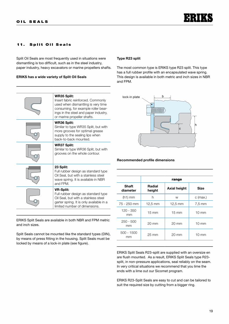
11. S p l i t O i l S ea l s
SplitOilSealsaremostfrequentlyusedinsituationsweredismantlingistoodifficult,suchasinthesteelindustry,paperindustry,heavyexcavatorsormarinepropellersshafts.
ERIKS has a wide variety of Split Oil Seals
ERIKSSplitSealsareavailableinbothNBRandFPMmetricandinchsizes.
SplitSealscannotbemountedlikethestandardtypes(DIN),bymeansofpressfittinginthehousing.SplitSealsmustbelockedbymeansofalock-inplate(seefigure).
Type R23 split
ThemostcommontypeisERIKStypeR�3split.Thistypehasafullrubberprofilewithanencapsulatedwavespring.ThisdesignisavailableinbothmetricandinchsizesinNBRandFPM.
Recommended profile dimensions
ERIKSSplitSealsR�3-splitaresuppliedwithanoversizeenareflushmounted.Asaresult,ERIKSSplitSealstypeR�3-split,innon-pressureapplications,sealreliablyontheseam.InverycriticalsituationswerecommendthatyoulimetheendswithalimeoutourSicometprogram.
ERIKSR�3-SplitSealsareeasytocutandcanbetailoredtosuittherequiredsizebycuttingfromabiggerring.
WR35 Split:Insert fabric reinforced. Commonly used when dismantling is very time consuming, for example roller bear-ings in the steel and paper industry, or marine propeller shafts.
WR36 Split:Similar to type WR35 Split, but with more grooves for optimal grease supply to the sealing lips when back-to-back mounted.
WR37 Split:Similar to type WR36 Split, but with grooves on the whole contour.
23 Split:Full rubber design as standard type Oil Seal, but with a stainless steel wave spring. It is available in NBR and FPM.
VR-Split:Full rubber design as standard type Oil Seal, but with a stainless steel garter spring. It is only available in a limited number of dimensions.
range
Shaft diameter
Radial height
Axial height Size
(h1) mm h w c (max.)
75 - 250 mm 12,5 mm 12,5 mm 7,5 mm
120 - 350 mm
15 mm 15 mm 10 mm
250 - 500 mm
20 mm 20 mm 10 mm
500 - 1500 mm
25 mm 20 mm 10 mm
hc
block-inplate

O I L S E A L S
�0
Type with insert fabric reinforcement
AlltheinsertfabricreinforcementOilSeals(general,andSplitSeals)aresuppliedwithaheightsizewhichis0,5to0,6mmlargerthandimensionb.Thelock-inplatere-formstheOilSealdiametricallywhichensuresreliablesealingontheshaftandthehousinginservice.
ERIKSinsertfabricreinforcementOilSealstypeWR35split,typeWR36splitandtypeWR37splitaremouldedandareprovidedwithaseam.Ifthedesiredsizeisnotavailableinthelist,pleasecontactus.ERIKShasmoresizesthanlisted.Pleaseallowadeliverytimeof8to�6weeks.
WhenassemblingtheseSplitSeals,itisnecessarytoremovethegarterspringfromthesealinglipandthenre-fititwhenthesealhasbeenmountedovertheshaft.
Comment:PleasetakeintoaccountthatwiththistypeofSplitSeal,theseam,whenmountedontheshaft,mustbeatthetop(��O’clock).Moreover,themediumtobesealedmustnotbeabovethecentrelineoftheshaft.
Type VR split
FortheassemblyoftheseSplitSeals,itisnecessarytoremovethegarterspringfromthesealinglipandthenre-fititwhenthesealhasbeenmountedontheshaft.
Comment:PleasetakeintoaccountthatwiththistypeofSplitSeal,theseam,whenmountedontheshaft,mustbeatthetop(��O’clock).Moreover,themediumtobesealedmustnotbeplacedabovethecentrelineoftheshaft.
ERIKSSplitSealstypeVR-Splitaremanufacturedcompletelyfromrubber,wheretheoutsideoftheOilSealhasahardnessof90°Shore“A”andtheinsidebodyandthesealingliphasahardnessofis70°Shore“A”.Thisdesignaswellthesealinglipiscentredbyahelicalspring.
ERIKSSplitSealstypeVR-Splitareavailableinalimitednumberofsizes.Werecommendthatyoutoinformusofyourrequirementsbeforeyouchooseoneofthesetypesofseals.
O I L S E A L S
��
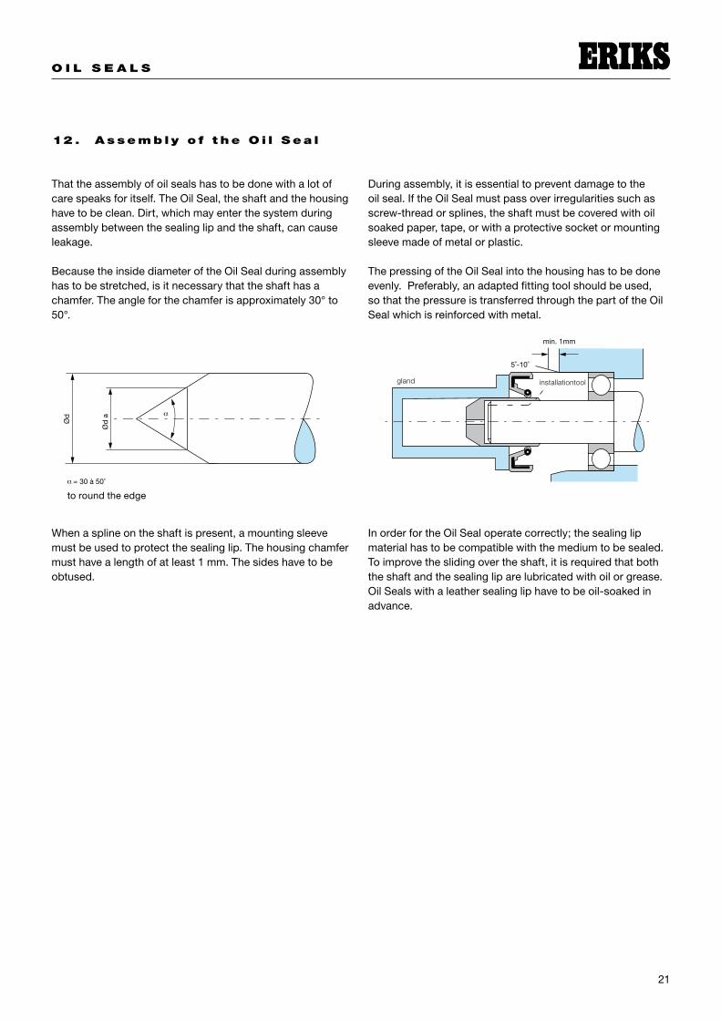
12 . As sem b l y o f t he O i l S ea l
Thattheassemblyofoilsealshastobedonewithalotofcarespeaksforitself.TheOilSeal,theshaftandthehousinghavetobeclean.Dirt,whichmayenterthesystemduringassemblybetweenthesealinglipandtheshaft,cancauseleakage.
BecausetheinsidediameteroftheOilSealduringassemblyhastobestretched,isitnecessarythattheshafthasachamfer.Theangleforthechamferisapproximately30°to50°.
Whenasplineontheshaftispresent,amountingsleevemustbeusedtoprotectthesealinglip.Thehousingchamfermusthavealengthofatleast�mm.Thesideshavetobeobtused.
Duringassembly,itisessentialtopreventdamagetotheoilseal.IftheOilSealmustpassoverirregularitiessuchasscrew-threadorsplines,theshaftmustbecoveredwithoilsoakedpaper,tape,orwithaprotectivesocketormountingsleevemadeofmetalorplastic.
ThepressingoftheOilSealintothehousinghastobedoneevenly.Preferably,anadaptedfittingtoolshouldbeused,sothatthepressureistransferredthroughthepartoftheOilSealwhichisreinforcedwithmetal.
InorderfortheOilSealoperatecorrectly;thesealinglipmaterialhastobecompatiblewiththemediumtobesealed.Toimprovetheslidingovertheshaft,itisrequiredthatboththeshaftandthesealingliparelubricatedwithoilorgrease.OilSealswithaleathersealingliphavetobeoil-soakedinadvance.
toroundtheedge
installationtoolgland
O I L S E A L S
��
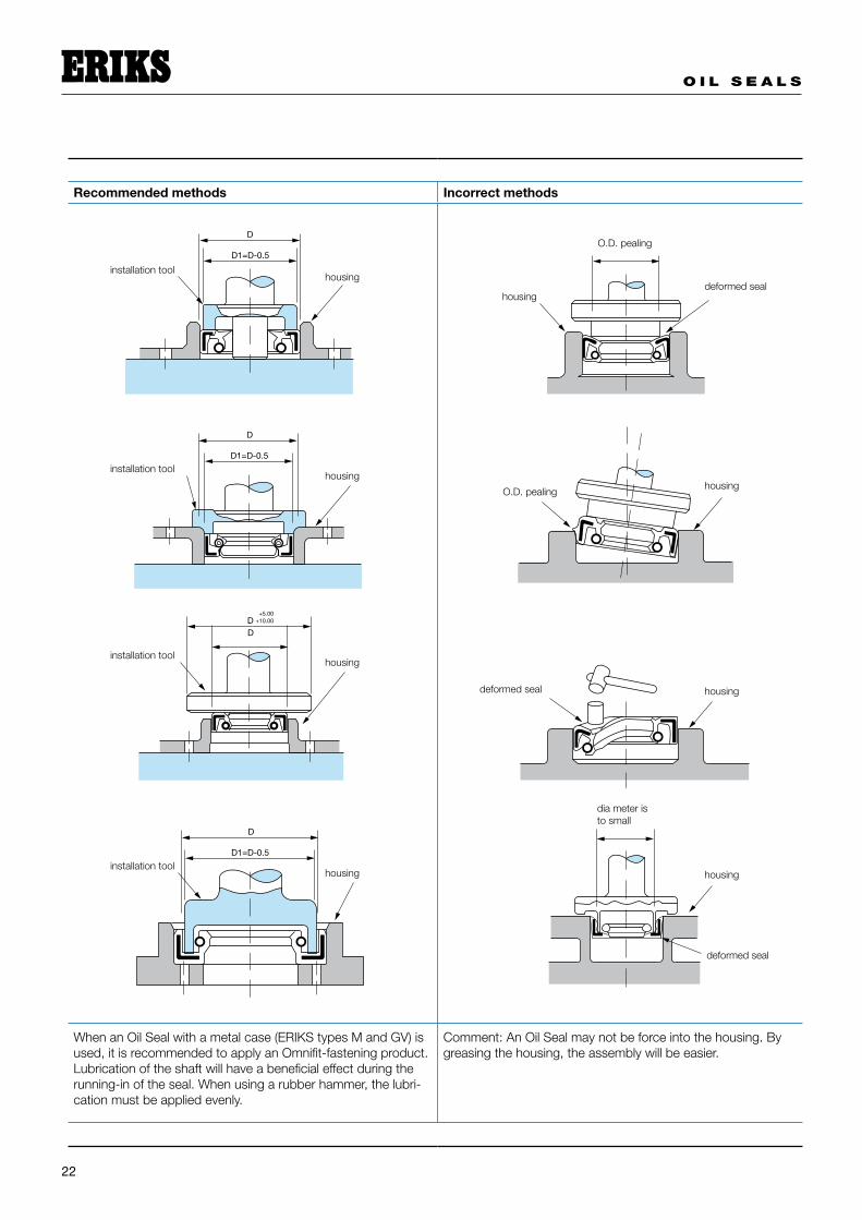
Recommended methods Incorrect methods
When an Oil Seal with a metal case (ERIKS types M and GV) is used, it is recommended to apply an Omnifit-fastening product. Lubrication of the shaft will have a beneficial effect during the running-in of the seal. When using a rubber hammer, the lubri-cation must be applied evenly.
Comment: An Oil Seal may not be force into the housing. By greasing the housing, the assembly will be easier.
D�=D-0.5
D
D�=D-0.5
D
DD
+5.00+�0.00
D�=D-0.5
D
installation toolhousing
installation toolhousing
installation toolhousing
installation toolhousing
housing
housing
housing
housing
deformed seal
deformed seal
deformed seal
O.D. pealing
O.D. pealing
dia meter isto small

O I L S E A L S
�3
13 . Tr ou b les hoo t i n g
Therearetwopotentialleakpathsonanoilseal,i.e.betweentheoutsidediameteroftheOilSealandthehousing(static),andbetweenthesealinglipandtheshaft(dynamic)
Inthetablebelowthecausesarelisted,withafewrecommendationstopreventtheseproblems.
Symptoms Cause Remedy
Oil Seal rotates with the shaftOutside diameter is smaller than the housing diameter
Replace the Oil Seal, choose the right size
Oil Seal is moving in an axial direction on the shaft
Outside diameter is smaller than the housing diameter Replace the Oil Seal, choose the right
sizeDue to excess pressure the Oil Seal is moving axially
The mounted Oil Seal is deformed Inside diameter of the Oil Seal is too small Control the size of the shaft
The case of the Oil Seal is deformed Wrong installation tools has been used Use the right tools
Damaged surface of the Oil Seal
The finishing has not been executed properly
Control the roughness of the housing and the presence of a chamfer
Dirt at the in- our outside of the housing Clean all parts before assembly
Damaged sealing lip
Insufficient lubrication Lubricate sufficiently
Construction limits the transport of the lubrication to the sealing lip
Change the construction so that sufficient lubrication reaches the sealing lip
Partly damaged sealing lipOil Seal not placed concentric with regards to the housing
Centre the seal, use the right tools
Sealing lip has hardened, is worn out and is torn
To high temperature, shaft speed, pressure
Choose the right rubber compound and type of Oil Seal
Insufficient lubrication Lubricate sufficiently
Swollen sealing lip Incorrect rubber compound Choose the correct material
Scraped sealing lipRoughness of the shaft is incorrect Control roughness
Incorrect tools used during assembly Choose correct assembly tool
Collapsed sealing lipIncorrect assembly Lubricate before the assembly
Too high pressure Choose an Oil Seal for high pressures
The flexible part is tornToo high pressure
Choose an Oil Seal for high pressuresPressure directed at the flexible part
Garter spring out the groove
Chamfer does not have the correct angleUse a mounting sleeve, or make a chamfer on the shaft
Incorrect assembly Take care during the assembly
Grooves not deep enoughChoose another design, or use a spring with a smaller diameter

O I L S E A L S
�4
Omrekeningstabel inches-millimeters
inches 0 1 2 3 4 5 6 7 8 90 - �5.400 50.800 76.�00 �0�.600 ��7.000 �5�.400 �77.800 �03.�00 ��8.600
0.397 �5.797 5�.�97 76.597 �0�.997 ��7.397 �5�.797 �78.�97 �03.597 ��8.9970.794 �6.�94 5�.594 76.994 �0�.394 ��7.794 �53.�94 �78.594 �03.994 ��9.394�.�9� �6.59� 5�.99� 77.39� �0�.79� ��8.�9� �53.59� �78.99� �04.39� ��9.79��.588 �6.988 5�.388 77.788 �03.�88 ��8.588 �53.988 �79.388 �04.788 �30.�88�.984 �7.384 5�.784 78.�84 �03.584 ��8.984 �54.384 �79.784 �05.�84 �30.584�.38� �7.78� 53.�8� 78.58� �03.98� ��9.38� �54.78� �80.�8� �05.58� �30.98��.778 �8.�78 53.578 78.978 �04.376 ��9.778 �55.�78 �80.578 �05.978 �3�.7783.�75 �8.575 53.975 79.375 �04.775 �30.�75 �55.575 �80.975 �06.375 �3�.3753.57� �8.97� 54.37� 79.77� �05.�7� �30.57� �55.97� �8�.37� �06.77� �3�.�7�3.969 �9.369 54.769 80.�69 �05.569 �30.969 �56.369 �8�.769 �07.�69 �3�.5694.366 �9.766 55.�66 80.566 �05.966 �3�.366 �56.766 �8�.�66 �07.566 �3�.9664.763 30.�63 55.563 80.963 �06.363 �3�.763 �57.�63 �8�.563 �07.963 �33.3635.�59 30.559 55.959 8�.359 �06.759 �3�.�59 �57.559 �8�.959 �08.359 �33.7595.556 30.956 56.356 8�.756 �07.�56 �3�.556 �57.956 �83.356 �08.756 �34.�565.953 3�.353 56.753 8�.�53 �07.553 �3�.953 �58.353 �83.753 �09.�53 �34.5536.350 3�.750 57.�50 8�.550 �07.950 �33.350 �58.750 �84.�50 �09.550 �34.9506.747 3�.�47 57.547 8�.947 �08.347 �33.747 �59.�47 �84.547 �09.947 �35.3477.�44 3�.544 57.944 83.344 �08.744 �34.�44 �59.544 �84.944 ��0.344 �35.7447.54� 3�.94� 58.34� 83.74� �09.�4� �34.54� �59.94� �85.34� ��0.74� �36.�4�7.938 33.338 58.738 84.�38 �09.538 �34.938 �60.338 �85.738 ���.�38 �36.5388.334 33.734 59.�34 84.534 �09.934 �35.334 �60.734 �86.�34 ���.534 �36.9348.73� 34.�3� 59.53� 84.93� ��0.33� �35.73� �6�.�3� �86.53� ���.93� �37.33�9.��8 34.5�8 59.9�8 85.3�8 ��0.7�8 �36.��8 �6�.5�8 �86.9�8 ���.3�8 �37.7�89.5�5 34.9�5 60.3�5 85.7�5 ���.��5 �36.5�5 �6�.9�5 �87.3�5 ���.7�5 �38.��59.9�� 35.3�� 60.7�� 86.��� ���.5�� �36.9�� �6�.3�� �87.7�� ��3.��� �38.5��
�0.3�9 35.7�9 6�.��9 86.5�9 ���.9�9 �37.3�9 �6�.7�9 �88.��9 ��3.5�9 �38.9�9�0.7�6 36.��6 6�.5�6 86.9�6 ���.3�6 �37.7�6 �63.��6 �88.5�6 ��3.9�6 �39.3�6��.��3 36.5�3 6�.9�3 87.3�3 ���.7�3 �38.��3 �63.5�3 �88.9�3 ��4.3�3 �39.7�3��.509 36.909 6�.309 87.709 ��3.�09 �38.509 �63.909 �89.309 ��4.709 �40.�09��.906 37.306 6�.706 88.�06 ��3.506 �38.906 �64.306 �89.706 ��5.�06 �40.506��.303 37.703 63.�03 88.503 ��3.903 �39.303 �64.703 �90.�03 ��5.503 �40.903��.700 38.�00 63.500 88.900 ��4.300 �39.700 �65.�00 �90.500 ��5.900 �4�.300�3.097 38.497 63.897 89.�97 ��4.697 �40.097 �65.497 �90.897 ��6.�97 �4�.697�3.494 38.894 64.�94 89.694 ��5.094 �40.494 �65.894 �9�.�94 ��6.694 �4�.094�3.89� 39.�9� 64.69� 90.09� ��5.49� �40.89� �66.�9� �9�.69� ��7.09� �4�.49��4.�88 39.688 65.088 90.488 ��5.888 �4�.�88 �66.688 �9�.088 ��7.488 �4�.888�4.684 40.084 65.484 90.884 ��6.�84 �4�.684 �67.084 �9�.484 ��7.884 �43.�84�5.08� 40.48� 65.88� 9�.�8� ��6.68� �4�.08� �67A8� �9�.88� ��8.�8� �43.68��5.478 40.878 66.�78 9�.678 ��7.078 �4�.478 �67.878 �93.�78 ��8.678 �44.078�5.875 4�.�75 66.675 9�.075 ��7.475 �4�.875 �68.�75 �93.675 ��9.075 �44.475�6.�7� 4�.67� 67.07� 9�.47� ��7.87� �43.�7� �68.67� �94.07� ��947� �44.87��6.669 4�.069 67.469 9�.869 ��8.�69 �43.669 �69.069 �94.469 ��9869 �45.�69�7.066 4�.466 67.866 93.�66 ��8.666 �44.066 �69.466 �94.866 ��0.�66 �45.666�7.463 4�.863 68.�63 93.663 ��9.063 �44.463 �69.863 �95.�63 ��0.663 �46.063�7.859 43.�59 68.659 94.059 ��9.459 �44.859 �70.�59 �95.659 ���.059 �46.459�8.�56 43.656 69.056 94.456 ��9.856 �45.�56 �70.656 �96.056 ���.456 �46.856�8.653 44.053 69.453 94.853 ��0.�53 �45.653 �7�.053 �96.453 ���.853 �47.�53�9.050 44.450 69.850 95.�50 ��0.650 �46.050 �7�.450 �96.850 ���.�50 �47.650�9.447 44.847 70.�47 95.647 ���.047 �46.447 �7�.847 �97.�47 ���.647 �48.047�9.844 45.�44 70.644 96.044 ���.444 �46.844 �7�.�44 �97.644 ��3.044 �48.444�0.�4� 45.64� 7�.04� 96.44� ���.84� �47.�4� �7�.64� �98.04� ��3.44� �48.84��0.638 46.038 7�.438 96.838 ���.�38 �47.638 �73.038 �98.438 ��3.838 �49.�38��.034 46.434 7�.834 97.�34 ���.634 �48.034 �73.434 �98.834 ��4.�34 �49.634��.43� 46.83� 7�.�3� 97.63� ��3.03� �48.43� �73.83� �99.�3� ��4.63� �50.03���.8�8 47.��8 7�.6�8 98.0�8 ��3.4�8 �48.8�8 �74.��8 �99.6�8 ��5.0�8 �50.4�8��.��5 47.6�5 73.0�5 98.4�5 ��3.8�5 �49.��5 �74.6�5 �00.0�5 ��5.4�5 �50.8�5��.6�� 48.0�� 73.4�� 98.8�� ��4.��� �49.6�� �75.0�� �00.4�� ��5.8�� �5�.����3.0�9 48.4�9 73.8�9 99.��9 ��4.6�9 �50.0�9 �75.4�9 �00.8�9 ��6.��9 �5�.6�9�3.4�6 48.8�6 74.��6 99.6�6 ��5.0�6 �50.4�6 �75.8�6 �0�.��6 ��6.6�6 �5�.0�6�3.8�3 49.��3 74.6�3 �00.0�3 ��5.4�3 �50.8�3 �76.��3 �0�.6�3 ��7.0�3 �5�.4�3�4.�09 49.609 75.009 �00.409 ��5.809 �5�.�09 �76.609 �0�.009 ��7.409 �5�.809�4.606 50.006 75.406 �00.806 ��6.�06 �5�.606 �77.006 �0�.406 ��7.806 �53.�06�5.003 50.403 75.803 �0�.�03 ��6.603 �5�.003 �77.403 �0�.803 ��8.�03 �53.603
�3�
��6
33�
�8
53�
3�6
73�
�4
93�
5�6
��3�
38
�33�
7�6
�53�
��
�73�
9�6
�93�
�8
��3�
���6
�33�
34
�53�
�3�6
�73�
78
�93�
�5�6
3�3�
�64
364
564
764
964
��64
�364
�564
�764
�964
��64
�364
�564
�764
�964
3�64
3364
3564
3764
3964
4�64
4364
4564
4764
4964
5�64
5364
5564
5764
5964
6�64
6364
14 . Conve r s i on t a b le i nch / m m
O I L S E A L S
�5
d�
b
d
95
�00
�05
��0
��5
��0
��5
�30
�35
�40
�45
�50
�60
�70
�80
�90
�00
��0
��0
�30
�40
�50
�60
�80
300
3�0
340
360
380
400
4�0
440
460
480
500
6
7
8
9
�0
��
�4
�5
�6
�8
�0
��
�5
�8
30
3�
�6
��
��
��
�4
��
��
�5
�6
��
�5
30
�4
30
�6
30
35
30
35
30
35
30
35
40
35
40
47
35
40
47
5�
40
47
5�
40
4�
47
5�
45
47
5�
45
47
5�
7
7
7
7
7
7
7
7
7
7
7
7
7
7
7
7
8
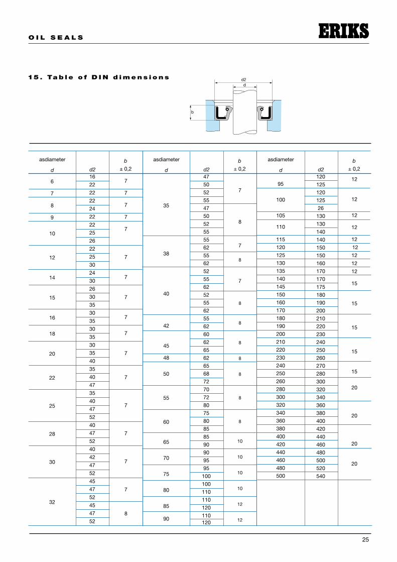
asdiameter
d d2
b
± 0,�
35
38
40
4�
45
48
50
55
60
65
70
75
80
85
90
47
50
5�
55
47
50
5�
55
55
6�
55
6�
5�
55
6�
5�
55
6�
55
6�
60
6�
65
6�
65
68
7�
70
7�
80
75
80
85
85
90
90
95
95
�00
�00
��0
��0
��0
��0��0
7
8
7
8
7
8
8
8
8
8
8
8
�0
�0
�0
�0
��
��
asdiameter
d d2
b
± 0,�
��0
��5
��0
��5
�6
�30
�30
�40
�40
�50
�50
�60
�70
�70
�75
�80
�90
�00
��0
��0
�30
�40
�50
�60
�70
�80
300
3�0
340
360
380
400
4�0
440
460
480
500
5�0
540
��
��
��
��
��
��
��
��
��
�5
�5
�5
�5
�5
�0
�0
�0
�0
asdiameter
d d2
b
± 0,�
15 . Ta b le o f D I N d imens ions