epv image vsc - amazon web...
TRANSCRIPT

EPV IMAGE VSC
VIDEO PROCESSOR USER MANUAL

Elation Support
Thank You for Purchasing the EPV IMAGE VSC
Thank you for your purchasing the Elation Professional EPV IMAGE VSC Scaler and LED wall control system. Please read the instructions in this manual carefully and thoroughly before attempting to operate this unit. These instructions contain important information regarding safety during use and maintenance. Please fill out and return the enclosed warranty card to validate your purchase.
Customer Service
Elation provides a toll free customer support line, to provide set up help and to answer any question should you encounter problems during you set up or initial operation. You may also visit us on the web at www.elationlighting.com for any comments or suggestions. All returned service items whether under warranty or not, must be freight pre-paid and accompany a Return Authorization (RA) number. The RA number must be clearly written on the outside of the return package. Items returned without a RA number clearly marked on the outside of the package will be refused and returned at customer’s expense. You may obtain a RA number by contacting customer service. A brief description of the problem as well as the RA number must be written down on a piece of paper and included in the shipping container. If the unit is under warranty, you must also provide a copy of your proof of purchase invoice. Customer Service hours are Monday through Friday 8:00 a.m. - 5:00 p.m. Pacific Standard Time. Toll Free: (866) 245-6726 Phone: (323) 582-3322 Fax: (323) 832-9142 Information: [email protected] Sales: [email protected] Support: [email protected] Forum: forums.elationlighting.com/eve

2-Year Limited Warranty Elation® hereby warrants, to the original purchaser, Elation Professional® products to be free of manufacturing defects in material and workmanship for a period of 2 Years (730 days) on all internal parts, components, and labor. This warranty shall be valid only if the product is purchased within the United States of America, including possessions and territories. It is the owner’s responsibility to establish the date and place of purchase by acceptable evidence, at the time service is sought. For warranty service, send the product only to the Elation factory. All shipping charges must be pre-paid. If the requested repairs or service (including parts replacement) are within the terms of this warranty, Elation will pay return shipping charges only to a designated point within the United States except Hawaii or Alaska. If the entire instrument is sent, it must be shipped in its original package. No accessories should be shipped with the product. If any accessories are shipped with the product, Elation shall have no liability whatsoever for loss of or damage to any such accessories, nor for the safe return thereof. This warranty is void if:
• The serial number has been altered or removed • The product is modified in any manner which Elation concludes, after
inspection, affects the reliability of the product • The product has been repaired or serviced by anyone other than the
Elation factory unless prior written authorization was issued to purchaser by Elation
• The product is damaged because not properly maintained as set forth in the instruction manual
This is not a service contract, and this warranty does not include maintenance, cleaning or periodic check-up. During the period specified above, Elation will replace defective parts at its expense, and will absorb all expenses for warranty service and repair labor by reason of defects in material or workmanship. The sole responsibility of Elation under this warranty shall be limited to the repair of the product, or replacement thereof, including parts, at the sole discretion of Elation. All products covered by this warranty were manufactured after January 1, 1990, and bear identifying marks to that effect. Elation reserves the right to make changes in design and/or improvements upon its products without any obligation to include these changes in any products theretofore manufactured.

No warranty, whether expressed or implied, is given or made with respect to any accessory supplied with products described above. Except to the extent prohibited by applicable law, all implied warranties made by Elation in connection with this product, including warranties of merchantability or fitness, are limited in duration to the warranty period set forth above. And no warranties, whether expressed or implied, including warranties of merchantability or fitness, shall apply to this product after said period has expired. The consumer’s and or Dealer’s sole remedy shall be such repair or replacement as is expressly provided above; and under no circumstances shall Elation be liable for any loss or damage, direct or consequential, arising out of the use of, or inability to use, this product. This warranty is the only written warranty applicable to Elation Products and supersedes all prior warranties and written descriptions of warranty terms and conditions heretofore published.
Revision
Format Time ECO# Description Principal
1.0 2010-12-23 0000 Release Lisa

CONTENT
1.0 Safety ........................................................................................... 1 2.0 Specification................................................................................... 1
2.1 Specification/Parameters ............................................................ 2 3.0 Connection ..................................................................................... 4
3.1 EPV IMAGE VSC Back Panel......................................................... 5 3.2 How to install ............................................................................ 7
4.0 Front Panel Keyboard Operation ........................................................ 7 4.1 EPV IMAGE VSC Operator Guideline.............................................. 8 4.2 Video Processor Menu ................................................................ 9
5.0 Communication Software Guideline.................................................. 14 5.1 Install Software ....................................................................... 14 5.2 Run EPV IMAGE VSC Console..................................................... 18
6.0 FAQ............................................................................................. 27 6.1 No output in target display........................................................ 27 6.2 VGA input could not work with EPV IMAGE VSC Console................ 27 6.3 DVI input could not work with EPV IMAGE VSC ............................ 27 6.4 Component input could not work with EPV IMAGE VSC.................. 28 6.5 User settings can not save ........................................................ 28 6.6 Can’t update main board software.............................................. 28 6.7 Display SDI1 or SDI2 in dual display mode.................................. 29 6.8 HDMI display shows blue screen ................................................ 29 6.9 Can’t be saved ALPHA value ...................................................... 29
7.0 Quick Start................................................................................... 30 7.1 Single-screen control ............................................................... 30 7.2 Set dual screen fade ................................................................ 32 7.3 Displaying subtitles and LOGO................................................... 33 7.4 How to control processor with console software by USB?............... 38 7.5 How to Use LINSN Ledset software? ........................................... 42
8.0 Appendix ..................................................................................... 44 8.1 AppendixⅠDownload the main board software............................. 44 8.2 Appendix II Download the IP software ........................................ 53 8.3 Appendix Ⅲ How to add tasks................................................... 55

EPV 701 User Manual Doc. No:RGB-RD-UM-V618E012 1
1.0 Safety
The general safety information in this summary is for operating person. Any requirement, please feel freely to contact our service engineer.
Power Source This product is intended to operate from a power source
between 85~265 volts rms . This product is only workable under
correct power condition, which is already mark on the back panel
of the power.
High Voltage There are many high voltage components inside.
Do not Remove Covers and Panels Do not remove Covers in any conditions. There are not any
spare components inside for maintenance, so do not maintain
this product by userrselves, any requirement, please feel free to
contact our service engineer. Keep heavy device from power
cord.
Grounding the Product and Use the Proper Fuse This product is grounded through the grounding conductor of
the power cord. To Avoid electrical shock, plug the power cord
into a properly wired receptacle before connecting to the product
input or output terminals.
Keep away from Magnet, Motor, TV and Transformer.
Guard Against Damp Keep using inside clean and dryness environment, once the
device get wet, must remove power cord right now.
Keep away Exploder Do not operate the device inside dangerous and easy
explosive gas, which it may make fire, blast or something without
expectation.
Keep away Pour Liquid and Fragment It is forbid to pour liquid, metal fragment or anything else
inside this device to avoid fire and other accident. Once that
happens, must remove power cord and try to make it clean
before power on again.
2.0 Specification
Safe
ty

EPV 701 User Manual Doc. No:RGB-RD-UM-V618E012 2
EPV IMAGE VSC series video processors are designed by the latest high
performance image processing technology. EPV IMAGE VSC can handle
following video without limit, include CVBS(Composite)、S-Video (YC)、YCbCr
、YPbPr、RGBHV(VGA)、DVI-D、HDMI、SDI(SD-SDI、HD-SDI) and VOIP
(Copper RJ45).
2.1 Specification/Parameters
Composite BNC Input Number of Inputs 3 Supported Standards PAL/NTSC Signal Level 1Vpp±3db (0.7V Video+0.3v Sync ) 75ohm Multiplex YCbCr S-video DIN4 Input Number of Inputs 1 Supported Standards PAL/NTSC Signal Level Y:1Vpp±3dB (0.7V Video+0.3v Sync ) 75ohm
U/V:0.7Vpp±3dB 75ohm
YPbPr BNC Input Number of Inpus BNC*3 Supported Standards analog HD input Signal Level Y:1Vpp±3dB (0.7V Video+0.3v Sync ) 75ohm
Pb/Pr:0.7Vpp±3dB 75ohm
VGA DB15 Input Number of Inputs 1 connetor Standard DB15 socket Supported Standards VGA-UXGA Signal Level R、G、B、Hsync、Vsync:0 to1Vpp±3dB (0.7V
Video+0.3v Sync ) 75 ohm black level:300mV Sync-tip:0V
DVI Input Number of Inputs 1 Connector Standard DVI-I socket Supported Standards SMPTE:625/25 PAL, 525/29.97 NTSC, 625/50p
PAL, 525/59.94p NTSC, 1080i50, 1080i59.94/60, 720p50 720p59.94/60 VESA : 800×600×60Hz , 1024×768×60Hz ,1280×768×60Hz , 1280×1024×60Hz ,
1600×1200×60Hz , 1920×1080×60Hz ,
1920×1080×50Hz Signal Level TMDS pwl,single pixel input,165MHz bandwidth Standard DVI 1.1

EPV 701 User Manual Doc. No:RGB-RD-UM-V618E012 3
SDI Input Number of Inputs 2 Connetor BNC Data Rate Range 19.4Mbps~1.5Gbps Supported Standards ITU-R BT.656,ITU-R BT.601,SMPTE 259M,
SMPTE 292, SMPTE 297 Equalization) Belden 1694A 100M HD1.485G , 350m SD
270Mbps SDI Loop-out Number of Loop-Throughs 1 Signal Level 800mV±10% DC Offset 0V±0.5V Rise/Fall Time HD1.485Gbps<270 ps ; SD 270 Mbps 0.4
ns~1.5ns Overshoot <10% Timing Jitter SD<0.2UI;HD<1.0UI Alignment Jitter <0.2UI HDMI Input Number of Inputs 2 Connector HDMI (standard type A interface) Supported Standards SMPTE:625/25 PAL, 525/29.97 NTSC, 625/50p
PAL, 525/59.94p NTSC, 1080i50, 1080i59.94/60, 720p50 ,720p59.94/60 VESA : 800×600×60Hz , 1024×768×60Hz ,1280×768×60Hz , 1280×1024×60Hz ,
1600×1200×60Hz , 1920×1080×60Hz ,
1920×1080×50Hz Signal Level TMDS pwl,single pixel input,165MHz bandwidth Standard HDMI 1.3 SDI Loop-out Number of Loop-Throughs 1 Signal Level 800mV±10% DC Offset 0V±0.5V Rise/Fall Time HD1.485Gbps<270 ps ; SD270 Mbps 0.4
ns~1.5ns Overshoot <10% Timing Jitter SD<0.2UI;HD<1.0UI Alignment Jitter <0.2UI DVI Output Number of Inputs 1 connetor Standard DVI-I interface Supported Resolution 800×600×60Hz , 1024×768×60Hz ,
1024×768×75Hz , 1280×768×60Hz ,

EPV 701 User Manual Doc. No:RGB-RD-UM-V618E012 4
1280×1024×60Hz , 1440×900×60Hz ,
1400×1200×60Hz , 1600×1200×60Hz ,
1920×1080×60Hz , 1920×1200×60Hz ,
2048×1152×60Hz Signal Level TMDS pwl,165MHz bandwidth
VGA Output Number of Inputs 1 connetor Standard DB15 socket Supported Resolution 800×600×60Hz , 1024×768×60Hz ,
1024×768×75Hz , 1280×768×60Hz ,
1280×1024×60Hz , 1440×900×60Hz ,
1400×1200×60Hz , 1600×1200×60Hz ,
1920×1080×60Hz , 1920×1200×60Hz ,
2048×1152×60Hz,2048×1536×60Hz Signal Level R、G、B、Hsync、Vsync:0 to1Vpp±3dB (0.7V
Video+0.3v Sync ) 75ohm black level:300mV Sync-tip:0V
HDMI Output Number of Outputs 1 Connetor HDMI (standard type A interface) Supported Standards 800×600×60Hz , 1024×768×60Hz ,
1024×768×75Hz , 1280×768×60Hz ,
1280×1024×60Hz , 1440×900×60Hz ,
1400×1200×60Hz , 1600×1200×60Hz ,
1920×1080×60Hz , 1920×1200×60Hz ,
2048×1152×60Hz Signal Level TMDS pwl,165MHz bandwidth
Function Source Switch Support every signal with alpha key operation PIP PIP for SD with HD and HD with HD Alpha Key support Extras Communication RS232 TCP/IP Power Supply 85-264V 2A IEC-3 Working Environment 0°C~45°C Stored Environment 10% to 90% Product Warranty 1year
Note: Specifications are subject to change without notice.
3.0 Connection

EPV 701 User Manual Doc. No:RGB-RD-UM-V618E012 5
3.1 EPV IMAGE VSC Back Panel
1、Dial the code switch;
2、 10/100M interface (copper RJ45). Used to connect the computer by
568B-568A twist-pair
3、USB interface,Used to connect the computer
4、RS232 interface (RJ11) for EPV IMAGE VSC processor. Used to connect the
computer;
5-6、HDMI input interface。Input the signal from HD player, DVD, computer, and
so on.
7-8、SDI Input BNC, used to support SD/HD SDI input。Input the video signal
from the HD player, HD projector. It can connect to the 7 or 8 interface on the
next EPV IMAGE VSC,using the 75ohm BNC.
9、SDI loop out BNC, used to loop input SDI signal to next SDI player.
10-11、Gigabit copper port, connect to LED screen.
12、Gigabit Transmitter card USB control interface; 13、Gigabit Transmitter card DVI input,connect to DVI output of EPV IMAGE VSC; (This Connection does not support hot-plugging)
EPV 701 User Manual Doc. No:RGB-RD-UM-V618E012 6
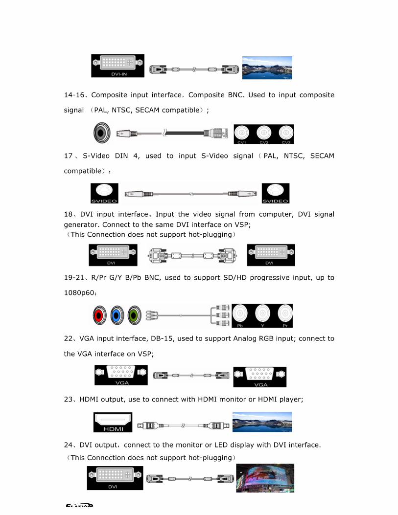
14-16、Composite input interface,Composite BNC. Used to input composite
signal (PAL, NTSC, SECAM compatible);
17、 S-Video DIN 4, used to input S-Video signal( PAL, NTSC, SECAM
compatible);
18、DVI input interface。Input the video signal from computer, DVI signal generator. Connect to the same DVI interface on VSP; (This Connection does not support hot-plugging)
19-21、R/Pr G/Y B/Pb BNC, used to support SD/HD progressive input, up to
1080p60;
22、VGA input interface, DB-15, used to support Analog RGB input; connect to
the VGA interface on VSP;
23、HDMI output, use to connect with HDMI monitor or HDMI player;
24、DVI output,connect to the monitor or LED display with DVI interface.
(This Connection does not support hot-plugging)

EPV 701 User Manual Doc. No:RGB-RD-UM-V618E012 7
25、VGA output interface, connect to the monitor, projector and so on;
26~27、Switch and power. It must use IEC-3 power line. Always ground to avoid
electric shock.
3.2 How to install
EPV IMAGE VSC frame size
4.0 Front Panel Keyboard Operation
Insert power cord and push power to ON position. LCD module on the front

EPV 701 User Manual Doc. No:RGB-RD-UM-V618E012 8
panel will show ELATION LIGHTING and go into self verification before it load
last setting config and send processed image to the target monitor. For the first
setup, CV1 input is default source. With front panel keyboard, user can operate
VSP with menu display on LCD module.
4.1 EPV IMAGE VSC Operator Guideline
EPV IMAGE VSC front panel as following:
1、LCD Module;
2、Keyboard:
ESC: push to exit from current choice item;
SEL: push to confirm the current choice item;
UP: push to select up items;
DOWN: push to select down items;
LEFT:push to select left items;
RIGHT:push to select right items;
CV1:switch to composite 1 input;
CV2:switch to composite 2 input;
CV3:switch to composite 3 input;
SVID:switch to s-video input;
YCbCr:switch to standard definition input;
VGA: switch to analog RGB input;
YPbPr: switch to high definition component;
DVI: Switch to DVI input;
SDI1:switch to SDI1 input;
SDI2:switch to SDI 2 input;
HDMI1:switch to HDMI 1 input;
HDMI2:switch to HDMI 2 input;
SAVE1:switch to use the user-defined mode 1;

EPV 701 User Manual Doc. No:RGB-RD-UM-V618E012 9
SAVE2:switch to use the user-defined mode 2;
PBP:switch to show two pictures beside on beside;
PIP:switch to show picture in picture on the screen. CV1 is the default
small picture on the top left corner, DVI is the default picture full
screen;
POP:switch to show picture out picture on the screen;
FS:switch to selet full screen or zoom view, just for single picture
mode;
MENU: push to go to main menu;
FRE:push to freeze the video image or live again
(FreezeLiveFreeze)
AB: push to switch between front picture and back picture if works in
dual channel mode with alpha key, front picture will alpha key in step by
step and back picture key out step by step;
SCALE: push to go to between scalezoomcropscale mode;
BRT:push to adjust the brightness and the contrast ratio, push to enter
to the relevant Menu, and then push the UP and DOWN to adjust the
brightness and the contrast ratio;
OUT: push to select the output format by using the UP and DOWN;
I/II: push to set single or dual channe;
SAVE: push to save current config;
4.2 Video Processor Menu
System menu as follows;

EPV 701 User Manual Doc. No:RGB-RD-UM-V618E012 10
Fig. 1
The first line shows EPV IMAGE VSC.
Push the right and left direction key to select the left or right menu. Before
the menu item, if there is a * sign, means the menu item has been selected;
you can push the Select key to enter it.
The � on the right means you can select the menu items by pushing the up
and down direction key.
User can check the information of the equipment in “Dev Info” menu
(including the manufacturer、serial-number );
User can get more service and support according to the serial-number.
User can check current input and output sources in Dev Info menu also.
Touch UP/DOWN to check System time
User can do a Factory Settings in Recall menu, after successful reset you will
see the menu as follows:
Push the MENU to enter the main menu, and then push up and down
direction key, the menu as follows:
Push the LEFT/RIGHT to select the relevant submenu.
LANGUAGE submenu as follows:
System time: 2009-08-17 15:12:35
Factory reset was completed !
Input: CV1 1024x768x60 Output: CV2 1024x768x60
ELATION LIGHTING >SN:3204
> EPV701 *Language Alpha ↑
> EPV701 *Dev Info Recall ↓

EPV 701 User Manual Doc. No:RGB-RD-UM-V618E012 11
Push UP/DWON to enter Alpha setup, user can set value from 0 to 100,
0 means video or graphic would be disappear and 100 means normal;
Port A and Port B stand for two channel picture;
Push OUT to enter the Output menu, push the UP or DOWN to select
different output resolution, push OK to confirm the output resolution.
Advance submenu as follows:
Added adjustable feature of DE;
Press UP/DOWN and select the menu as shown in Figure 1:
Figure 1
Press LEFT/RIGHTand select XY_Pos to enter the submenu of adjusting effective area;
XY_Pos:The sub-menu of which is used to adjust the position of overall effective area shown on the screen or monitor. H_BLANK: The overall effective area can be moved around by adjusting the value of H_BLANK. V_BLANK:The overall effective area can be moved up and down by adjusting the value of V_BLANK.
Added adjustable feature of DE,support the following resolution:
"800x600x60 Hz "、"1024x768x60 Hz "、"1024x768x75 Hz "
Note: "1280x1024x60 Hz "、"1400x1050x60 Hz "、"1600x1200x60 Hz "
H_BLANK *HS: 46
V_BLANK *VS: 38
> EPV701 *Advance XY_Pos ↑
Screen parameter: Hsize: 1024
*Alpha Port A Value: 100
*LANGUAGE >Chinese English

EPV 701 User Manual Doc. No:RGB-RD-UM-V618E012 12
Step:user can set the step of scale;
HSize:set the horizontal size of the image;
VSize:set the vertical size of the image;
HPos:set the horizontal position of the image;
VPos:set the vertical position of the image;
User can set size and position of the screen simply, Mainly applies to LED
screens users. After setting screen parameter, the user choice PIP or PBP
operation, display picture can directly shows on corresponding screen。
Push the�/�to enter Single or Dual channel menu , push the UP / DOWN to
select the single or dual channel, push SEL to confirm the single channel or
dual channel work state;
Select the input channel, push the UP/DOWN, and SEL to confirm the
different input channel. User can also push the channel name on the
keyboard to go into the input channel.
AB in EPV IMAGE VSC is for two image Alpha in and out.
OR:
Screen parameter: Hsize: 1024
Setup A on B
Setup Single
Source Select >CV1
Setup Dual
Output >1024x768x60

EPV 701 User Manual Doc. No:RGB-RD-UM-V618E012 13
Push SCALE to set the size and position of the image, push UP/DOWN and
SEL to confirm the relevant items;
Step:user can set the step of scale;
HSize:set the horizontal size of the image;
VSize:set the vertical size of the image;
HPos:set the horizontal position of the image;
VPos:set the vertical position of the image;
Push the FRE to freeze the live image or live the freeze image.
OR:
Push BRT to set the brightness and the contrast ratio:
OR:
Push SAVE and then push SAVE1 or SAVE2 to save the operation to SAVE1 or
SAVE2;Push SAVE1 or SAVE2 to execute relative operation after user save
the operation sucessfully.
Select Save Mode ! Push Esc To Exit
> EPV701 Contrast 50 ↑
> EPV701 Brightness 50 ↓
Live Frame Once gain for live
Freeze Frame Once gain for live
Setup A on B
Scale > Step 10
EPV 701 User Manual Doc. No:RGB-RD-UM-V618E012 14
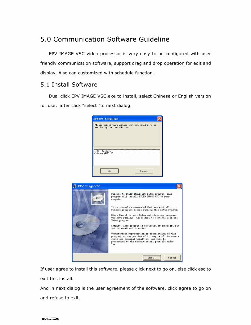
5.0 Communication Software Guideline
EPV IMAGE VSC video processor is very easy to be configured with user
friendly communication software, support drag and drop operation for edit and
display. Also can customized with schedule function.
5.1 Install Software
Dual click EPV IMAGE VSC.exe to install, select Chinese or English version
for use,after click “select ”to next dialog.
If user agree to install this software, please click next to go on, else click esc to
exit this install.
And in next dialog is the user agreement of the software, click agree to go on
and refuse to exit.

EPV 701 User Manual Doc. No:RGB-RD-UM-V618E012 15
If users agree to the agreement, user can select install directory in next
dialog, else, click next to install software to default directory “C:\Program Files”.
Click “next”to go on.

EPV 701 User Manual Doc. No:RGB-RD-UM-V618E012 16
Click “next” to go on.
Click “finish” and ready to run EPV IMAGE VSC console.

EPV 701 User Manual Doc. No:RGB-RD-UM-V618E012 17
EPV 701 User Manual Doc. No:RGB-RD-UM-V618E012 18
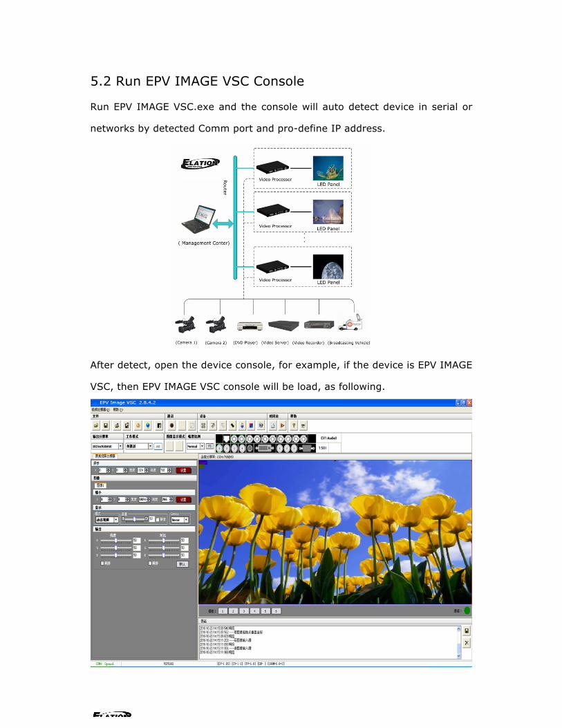
5.2 Run EPV IMAGE VSC Console
Run EPV IMAGE VSC.exe and the console will auto detect device in serial or
networks by detected Comm port and pro-define IP address.
After detect, open the device console, for example, if the device is EPV IMAGE
VSC, then EPV IMAGE VSC console will be load, as following.

EPV 701 User Manual Doc. No:RGB-RD-UM-V618E012 19
Setup Communication
EPV IMAGE VSC Console support COM port or Ethernet (UDP) to access EPV
IMAGE VSC.For the first running ,user must click the to close COM Port.
Click to change the COM Port and the Baudrate.
Serial: user can make choice between existent com ports and baud rates;
default Baudrate is 115200.
Ethernet: user can fill any number less than 1023 in Local Port. The Remote Port
must be 192.168.0.100 and the Remote Port must be 1000.
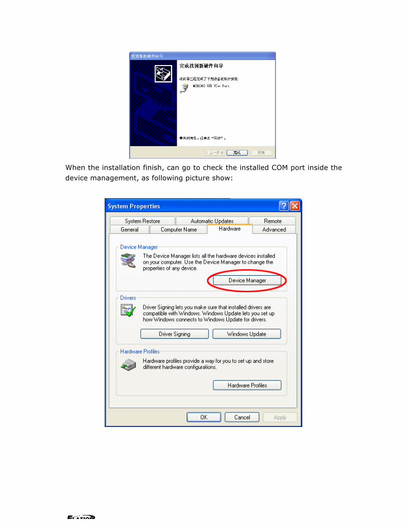
The COM Port is decided by user’s COM. Right click my computer icon on
desktop, select HardwareDevice Manager in the system attributes dialog. The
COM in red in the picture is the COM user can make choice.
EPV 701 User Manual Doc. No:RGB-RD-UM-V618E012 20
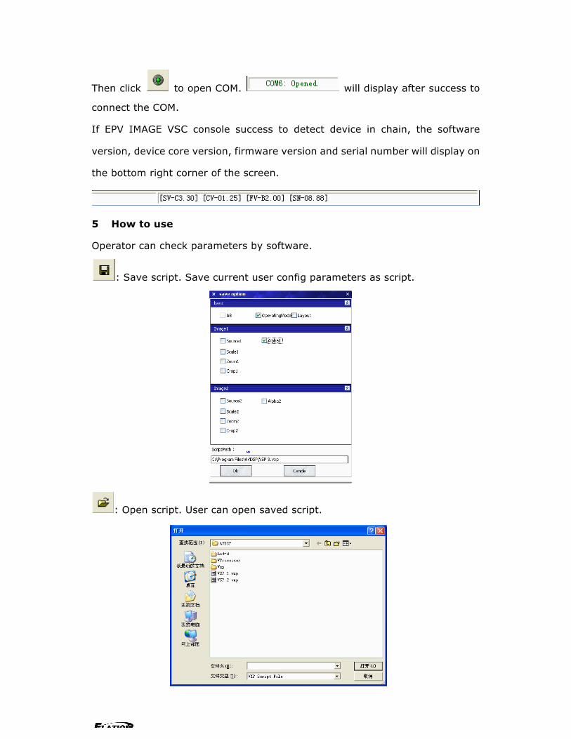
Then click to open COM. will display after success to
connect the COM.
If EPV IMAGE VSC console success to detect device in chain, the software
version, device core version, firmware version and serial number will display on
the bottom right corner of the screen.
5 How to use
Operator can check parameters by software.
: Save script. Save current user config parameters as script.
: Open script. User can open saved script.

EPV 701 User Manual Doc. No:RGB-RD-UM-V618E012 21
: Import template. There are six templates for user.
: Export template. Export current config as template.
: Option. User can choose open device when start and using script saved
before or execute schedule edited before when start.
If user choose open device when start, user can use last run, use script file or
none when user start. User can click to choose which script user want to
open.
If user choose execute schedule when start, the next dialogue will display when
software run.

EPV 701 User Manual Doc. No:RGB-RD-UM-V618E012 22
: Language. The software supports Chinese and English version. The
picture following is the Chinese dialogue.
: Exit.
Communication
: Open COM.
: Close COM.
: Set COM.
Device
: Synchronization.
: Save to flash.
:Load form Flash.
: Factory setup
: Advance, for adm. inistrator control.
: Execute schedule or stop schedule.
Help
: Help. Display helps dialogue.

EPV 701 User Manual Doc. No:RGB-RD-UM-V618E012 23
: About.
Output resolution: user can choose different output resolution by selecting
from pull down list.
Operating mode: choose to work in single channel or dual channel.
Layout: if in dual channel mode, user can set the device to work in PIP or PBP
mode directly with quick preset layout button as following.
Input: the white area display the name of input interface when the mouse is
over the interface picture on the left. The orange pane means current selected
interface.
If work in dual channel, channel 1 includes VOIP, CV1, CV2, CV3, SVideo, YCbCr,
SDI 1 and SDI 2, and channel 2 includes DVI, YPbPr, VGA, HDMI1 and HDMI 2.
The cross over interface picture means they can not access. The orange pane
means selected interface for channel 1. The blue pane means selected interface
for channel 2.
Screen parameter:
EPV 701 User Manual Doc. No:RGB-RD-UM-V618E012 24
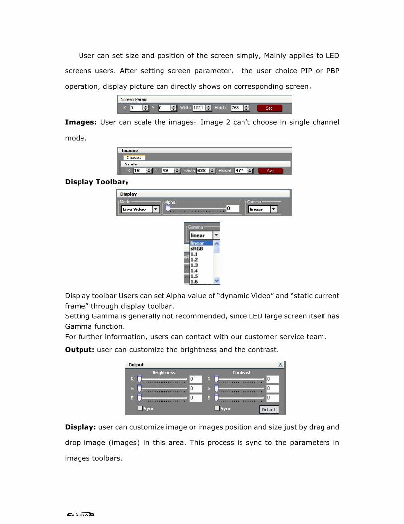
User can set size and position of the screen simply, Mainly applies to LED
screens users. After setting screen parameter, the user choice PIP or PBP
operation, display picture can directly shows on corresponding screen。
Images: User can scale the images;Image 2 can’t choose in single channel
mode.
Display Toolbar:
Display toolbar Users can set Alpha value of “dynamic Video” and “static current frame” through display toolbar. Setting Gamma is generally not recommended, since LED large screen itself has Gamma function. For further information, users can contact with our customer service team.
Output: user can customize the brightness and the contrast.
Display: user can customize image or images position and size just by drag and
drop image (images) in this area. This process is sync to the parameters in
images toolbars.

EPV 701 User Manual Doc. No:RGB-RD-UM-V618E012 25
Log: user can save or delete the operate log file.
Added functions
Alpha delay time Alpha can set AB button Fade effect.
IP set Users can set equipment IP, Usually used under the condition of one computer control or remote control several computers.
Clock Users can set or adjust lower computer time through” clock”

EPV 701 User Manual Doc. No:RGB-RD-UM-V618E012 26
Equipment Schedule function Users can set device to work with schedule, and then device can automatically switch between single or dual channel, resize image, switch video and with fade effect in need. Equipment currently supports max 10 regular content; users can set in the “timing” option.
Specifically how to implement devising schedule function, please refer to Appendix �.

EPV 701 User Manual Doc. No:RGB-RD-UM-V618E012 27
6.0 FAQ
6.1 No output in target display
1) Check the output config of the input video.
2) Check the input channel config is ok. Ex.The composite 1 interface is
connected to the composite interface of video source.
3) Check the connection of output is ok.
4) Check the target monitor or display is not destroied or power down.
5)Check the output resolution of EPV IMAGE VSC is not out of the maximal
resolution
of target display.
6) Check ALPHA value is not 0.
7)Any requirement, please feel free to contact our customer service engineer.
6.2 VGA input could not work with EPV IMAGE VSC Console
1)Check VGA source output is ok.
2)Check VGA input resolution is not out of EPV IMAGE VSC Console support list,
as following. The biggest input resolution is 1024*768*60Hz
3) Check EPV IMAGE VSC Console works in VGA input mode.
4) Any requirement, please feel free to contact our customer service engineer.
6.3 DVI input could not work with EPV IMAGE VSC
1) Check DVI source is ok.
2) Check DVI source output is not out of EPV IMAGE VSC support list.
3) Check EPV IMAGE VSC works in DVI input mode.
4) Check the connection between EPV IMAGE VSC and DVI source is correct.
Restart DVI source and check output.
5) Any requirement, please feel free to contact our customer service engineer.

EPV 701 User Manual Doc. No:RGB-RD-UM-V618E012 28
6.4 Component input could not work with EPV IMAGE VSC
1) Check the connection between EPV IMAGE VSC and Component source is
correct. Especially Y signal. Refer to cabling example in page 5. High Definition
component YPbPr is only support in YPbPr input。Standard definition YCbCr
support 480i and 576i only; High Definition YPbPr support 480i、576i、480P、
576P、720P50、720P60、1080i50 and 1080i60;
2) Check component source works, normally DVD component output should be
open from its menu.
3) No recommend to output component and SVideo input from the same source.
4) Any requirement, please feel free to contact our customer service engineer.
6.5 User settings can not save
EPV IMAGE VSC supports multi config mode. For multi config mode, the equipment starts to work automatically with the SAVE1 mode. According to different equipments, you can solve the problems that modes can’t be saved by the following steps. EPV IMAGE VSC Confirm to press the “SAVE” button, then press “SAVE1”,or “SAVE2”, that will save the current operation mode to the “user mode 1”,or ”user mode 2”, after that, gently push button “SAVE1”,””SAVE2, it will call out the corresponding setting of user-mode. If that, the saving is successful. After saving process, user should not do factory reset or any saving operation to user mode 1, otherwise, “SAVE1” will be over write.
6.6 Can’t update main board software
Connect the computer and EPV IMAGE VSC Series, select *.mot. Download file
to device.
After the equipment power up, right-click the “.mot” file at the left side of menu,
when the screen shows “waiting for update”, you can update the main board
program. Next, choose the “download file to device”, start to loading.

EPV 701 User Manual Doc. No:RGB-RD-UM-V618E012 29
6.7 Display SDI1 or SDI2 in dual display mode The way to display SDI1 or SDI2 in dual display mode: select SDI1 or SDI2 when in single display mode, press �/� to enter into dual display mode then select SDI1 or SDI2 as source signal
6.8 HDMI display shows blue screen In dual channel and the picture composition is: SDI+HDMI(including SDI1, SDI2 and HDMI1, HDMI2 combine together), switching between SDI1 and SDI2, or other signals switching to SDI1 or SDI2, when HDMI display shows blue screen, then user needs to reselect the HDMI working signal.
6.9 Can’t be saved ALPHA value ALPHA value can’t be saved when operating the AB key on the front panel to do FADE IN FADE OUT, so user has to revise the corresponding value in the Advanced Menu to save it.

EPV 701 User Manual Doc. No:RGB-RD-UM-V618E012 30
7.0 Quick Start
7.1 Single-screen control
Set screen parameters
Users can easily change the screen size and location by setting the parameters
with keyboard and LCD menu.
Press MENU to access main menu, Menu shows as below picture:
Press UP / DOWN button to turn the menu shown as below pictures:
Step: Set the unit of zoom and move every time;
HSize:Set Horizontal size;VSize:Set vertical size;
Hpos:Set horizontal coordinates(horizontal phase);
VPos:Set vertical size(vertical phase);
Scale pictures
Step:Set the unit of scale and move every time; (Three steps available:1,
10,100)
HSize:Set horizontal size; VSize:Set vertical size;
HPos:Set horizontal coordinates(horizontal phase);
VPos:Set vertical size(vertical phase);
Set alpha Enter Alpha sub-menu can set the alpha of video, Press UP /DOWN to set the value of alpha; Port A and Port B represent two video channels;
Scale > Step 10
>EPV IMAGE VSC *Dev Info Recall ↓
Screen parameter: Hsize: 1024
>EPV IMAGE VSC *Advance ↑
*Alpha Port A Value: 100

EPV 701 User Manual Doc. No:RGB-RD-UM-V618E012 31
Set brightness contrast
BRT brightness and contrast button can set brightness and contrast of active
window video shown as below pictures:
BRT brightness and contrast button can set brightness and contrast of active
window video shown as below pictures:
Freeze Frame
Press FRE static frame button can freeze, press the button can freeze current
active window image; You can make the screen switch between static and
active with this button; Pictures show as below:
or
EPV IMAGE VSC Contrast 50 ↑
EPV IMAGE VSC Brightness 50 ↓
EPV IMAGE VSC Contrast 50 ↑
EPV IMAGE VSC Brightness 50 ↓
Live Frame Once gain for live
Freeze Frame Once gain for live

EPV 701 User Manual Doc. No:RGB-RD-UM-V618E012 32
7.2 Set dual screen fade
1. Press �/� button to switch between single channel or dual channel. Menu is
as follows:
2.Choose two input source from CV1、CV2、 CV3 、SVID、 DVI、YPbPr、VGA、
SDI1、SDI2、HDMI and HDMI2.
3. Press AB button to realize dual screen fade.
CV1、CV2、 CV3 、SVID、SDI1 and SDI2 is small screen defaully, DVI、YpbPr、
VGA、HDMI1 and HDMI2 is big screen defaully while realizing dual screen, If you
want the two faded screens the same size, you can set the screen size by SCALE
button. For LED users, who are familiar with studio operation can also set the
display window on PC with studio software by the third party. And PC output by
VGA or DVI, Use SCALE to make the CV1、CV2、 CV3 、SVID、SDI1 and SDI2
the same size as studio display window. AB button can quickly realize dual
screen fade;
Step:Set the unit of zoom and move every time;
(Device default three step:1, 10,100)
HSize:set horizontal size; VSize:set vertical size;
HPos:Set horizontal coordinates(horizontal phase);
VPos:Set vertical size(vertical phase);
Press LEFT/RIGHT keys or touch UP/DOWN,select menu; * in front of the menu
means this menu is selected. Press SEL key, you can enter corresponding menu
to set and view.
Setup Single
Setup Dual
Scale > Step 10

EPV 701 User Manual Doc. No:RGB-RD-UM-V618E012 33
7.3 Displaying subtitles and LOGO
Users could add subtitles and Logo on the video by "set subtitle" option in "Video Processor" menu Subtitles switch By "subtitles switch" function, users can choose whether to display subtitles and subtitles background on the video.
Note: Subtitles show on top of the image without subtitle background.
Foreground transparency refers to subtitles’s transparency and background
transparency refers to subtitles background, which defaults to be 50% transparent, user can not adjust the value of this transparency.
Displaying Subtitles Fill in the subtitles blank with words that you need to show on display(eg. Advertising Slogans), maximum 80 characters allowed. Then click the “submit” button, subtitles will appear on the screen soon.
Note: Size of subtitles is limited, Chinese fonts defaults to be Times New Roman and size is 24X24 (pixels); English font defaults to be Arial, size of 16X24 (pixels). The subitle font could not be modified at present.
Subtitles color or subtitles background color Users can change the subtitles color or subtitles background color through dragging the scroll bar by mouse or make choice in the color palette to select the right color

EPV 701 User Manual Doc. No:RGB-RD-UM-V618E012 34
Subtitles movement Figuration of parameters in the "subtitles rolling" menu, subtitles could be rolling or static, at present, the device supports horizontal rolling( left or right) only, vertical rolling is not available at present.
Subtitle rolling Speed Through dragging the scroll bar by mouse to set the speed of rolling subtitles.
Subtitles position By setting the value of horizontal or vertical coordinates, subtitles position on the screen can be adjusted. Subtitles Width refers to the width of the subtitles display area. As long as the parameters have been set, subtitles will be displayed in the figurated area.

EPV 701 User Manual Doc. No:RGB-RD-UM-V618E012 35
LOGO display Users could made any LOGO displayed by the LOGO display function. Users can choose whether to enable the LOGO display function according to circumstance. When users select the "background color mark", the screen background color would be black and LOGO shows on it. When users select "trademark transparent", LOGO would be translucent.
When users select "trademark transparent", LOGO would be translucent. Note:
The value of this transparency could not be modified.
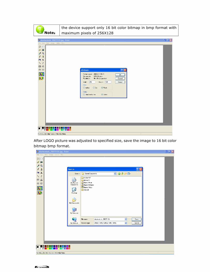
Users could change the image format and pixels with software in window OS. The picture would be cut on the right side and bottom if it is too big. If the current picture is larger than the new size, the right side and the bottom part of the picture will be cut off in order to adapt to smaller areas. If the image is too big, users would have to cut the picture first. by the Toolbox.
Change image size, and then click "properties” on "image" menu, and select the width and height of the measurement in pixels. Enter the width and height values in the "width" and "height" box.
EPV 701 User Manual Doc. No:RGB-RD-UM-V618E012 36
Note: the device support only 16 bit color bitmap in bmp format with maximum pixels of 256X128
After LOGO picture was adjusted to specified size, save the image to 16 bit color bitmap bmp format.

EPV 701 User Manual Doc. No:RGB-RD-UM-V618E012 37
Download LOGO After LOGO picture was adjusted to specified format and size, users could download it to the device, and then enable the LOGO display function, the LOGO would be displayed on the screen. By setting the parameters of X or Y coordinates, LOGO position on screen can be adjusted.

EPV 701 User Manual Doc. No:RGB-RD-UM-V618E012 38
7.4 How to control processor with console software by USB?
1. Install the driver; Connect the USB cable to the PC and the video processor. Turn on the EPV IMAGE VSC for the first time to use USB, the PC will remind finding the new hardware and ask to install the driver for this new driver.
Install from the list or specified location, press “NEXT”:
Press “ browser” to find the driver, and press “NEXT”
EPV 701 User Manual Doc. No:RGB-RD-UM-V618E012 39
When the installation finish, can go to check the installed COM port inside the device management, as following picture show:

EPV 701 User Manual Doc. No:RGB-RD-UM-V618E012 40
2. Install the console software, and run after install, shows the interface of the
console as following:

EPV 701 User Manual Doc. No:RGB-RD-UM-V618E012 41
:Set the RS232 as installed just now, and set the EPV IMAGE VSC Boud
Rate to be: 115200.
Press to start RS 232 communication, when there is green point in the
right down corner showing on the software, it means the communication is OK,
and you can use the software to control the device now; the software operation
is the same as EPV IMAGE VSC, just can see the difference of the SDI input;
Note:
If power off during communication, should close the port
by first, and plug in out of the USB and do communication
again.
EPV 701 User Manual Doc. No:RGB-RD-UM-V618E012 42
7.5 How to Use LINSN Ledset software?
1. First, Install EPV IMAGE VSC software and LINSN software.
2. Run EPV IMAGE VSC software;
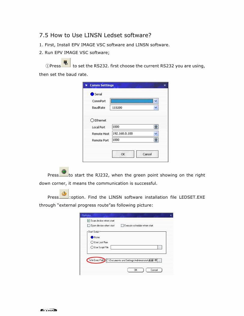
①Press to set the RS232. first choose the current RS232 you are using,
then set the baud rate.
Press to start the RJ232, when the green point showing on the right
down corner, it means the communication is successful.
Press :option. Find the LINSN software installation file LEDSET.EXE
through “external progress route”as following picture:

EPV 701 User Manual Doc. No:RGB-RD-UM-V618E012 43
As LINSN software will use RS232 for communication too, so user should first close EPV IMAGE VSC console software RS232 communication after that press
;
If in used , then to start the LINSN software. When you want to use EPV
IMAGE VSC software, you just need to close LINSN software, start the
RS232 again.
Note::
Before using EPV IMAGE VSC console software to execute the
LINSN software, you should first internally connect the device's
100M board with sending card.
Any question, please feel free to contact our customer service
engineer.

EPV 701 User Manual Doc. No:RGB-RD-UM-V618E012 44
8.0 Appendix
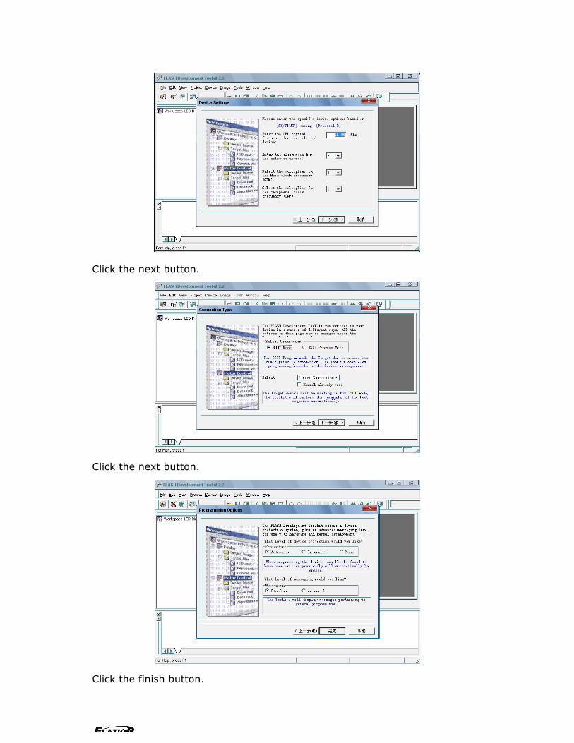
8.1 Appendix�Download the main board software
Installation
Double-click fdt2_2 setup.exe.
Click the next button.
Click the yes button.
Click the next button.

EPV 701 User Manual Doc. No:RGB-RD-UM-V618E012 45
Click the next button.
Unselected the H8S/2000, H8S/2000, H8. Click the next button.
Select 7144.45, Click the OK button.

EPV 701 User Manual Doc. No:RGB-RD-UM-V618E012 46
Select the location by browse. Click the next button.
Click the next button.
Click the next button.

EPV 701 User Manual Doc. No:RGB-RD-UM-V618E012 47
Click the finish button. It’s ok.
Download
Open the Flash Development Toolkit 2.2.
Click the OK button.

EPV 701 User Manual Doc. No:RGB-RD-UM-V618E012 48
Fill the name. Click the OK button.
Click the (Y)button.
Click the (Y)button.

EPV 701 User Manual Doc. No:RGB-RD-UM-V618E012 49
Fill the name. Click the OK button.
Select the sh/7145f. Click the next button.
Select the COM port. Click the next button.
EPV 701 User Manual Doc. No:RGB-RD-UM-V618E012 50
Click the next button.
Click the next button.
Click the finish button.

EPV 701 User Manual Doc. No:RGB-RD-UM-V618E012 51
Select project/properties/communications. select the COM port in user setting.
Do not check User default baud rate and select Target Baud as 9600.
Click the target files by the right mouse. Select add files to project , and select
user *.mot.
EPV 701 User Manual Doc. No:RGB-RD-UM-V618E012 52
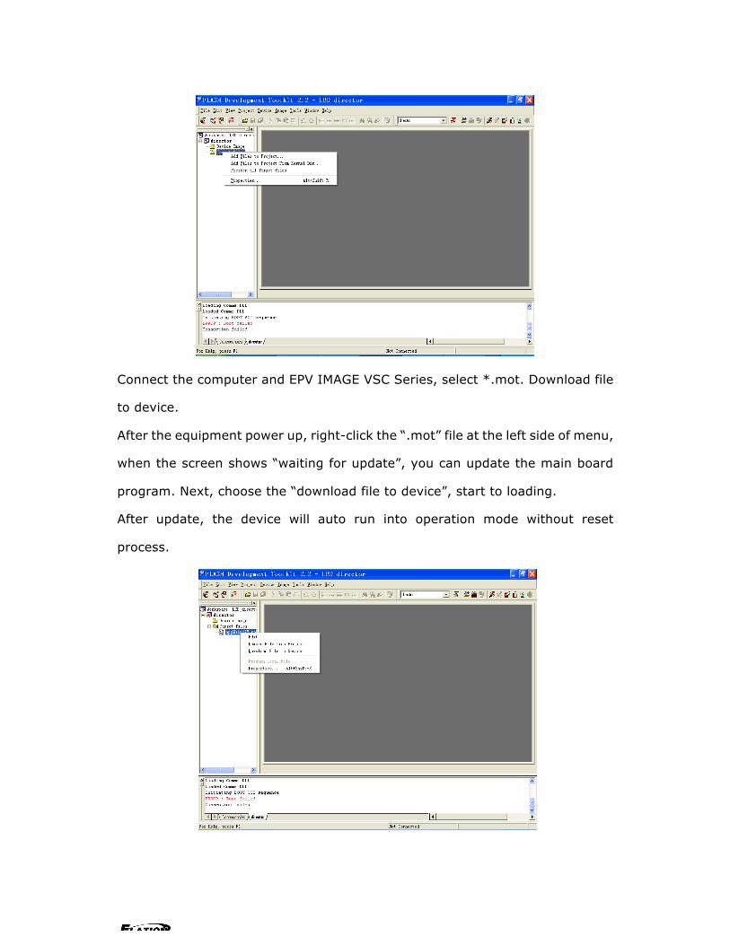
Connect the computer and EPV IMAGE VSC Series, select *.mot. Download file
to device.
After the equipment power up, right-click the “.mot” file at the left side of menu,
when the screen shows “waiting for update”, you can update the main board
program. Next, choose the “download file to device”, start to loading.
After update, the device will auto run into operation mode without reset
process.
EPV 701 User Manual Doc. No:RGB-RD-UM-V618E012 53
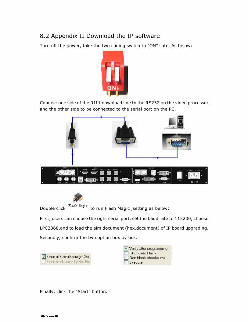
8.2 Appendix II Download the IP software
Turn off the power, take the two coding switch to “ON” sate. As below:
Connect one side of the RJ11 download line to the RS232 on the video processor, and the other side to be connected to the serial port on the PC.
Double click to run Flash Magic ,setting as below:
First, users can choose the right serial port, set the baud rate to 115200, choose
LPC2368,and to load the aim document (hex.document) of IP board upgrading.
Secondly, confirm the two option box by tick.
Finally, click the “Start” button.

EPV 701 User Manual Doc. No:RGB-RD-UM-V618E012 54
After download, exit the program, turn off the power, tack the two coding switch
back, as below, restart the equipment power, check if the equipment work
normally.

EPV 701 User Manual Doc. No:RGB-RD-UM-V618E012 55
8.3 Appendix � How to add tasks. Use “Device Schedule” can add tasks,make device automatically run to the Schedule input source in specified time or schedule display modes such as fade in and out. First of all,set lower computer current time through host computer “clock”.
Note: Reset to factory settings after setting the clock will affect the time before.
After Clock setting, users can check whether successfully set through button. Press MENU button to enter system main menu, then press Dev Info (device information), then press SEL button can show device information. Touch /DOWN,check in the System time. Shown as below picture:
After device clock set, add task plan through” Timing Parameters”.
1. Users need to start “time-enabled” before using” timing device”. If you forget to start, time set may fail.
Click “start” button , when the button changes to , it means
System time: 2009-08-17 15:12:35

EPV 701 User Manual Doc. No:RGB-RD-UM-V618E012 56
time can start. Press MENU button can enter system main menu, touch UP/DOWN to enter advanced menu, shown as the picture:
Press SEL button to enter advanced menu
2. When the timer count is set to 1, it indicates that the setting contents will be stored in the “timing 1”. If you need to set more, you can set up one by one and
saved in different “Timer index”.
Note: Equipment currently supports 10 task scheduler.
3. Set “task schedule” playing time,can up to second.
4. Select the signal source to play works in dual channel or single channel mode, and check whether to use fade during dual channel mode.
5. Users can control the image position and size by change the data or click the drop-down arrow.
6. When device works under the single channel mode, click the interface Icon.
Red box indicates current interface has been selected as the input interface;
When device works under the dual channel mode, need to switch image 1 and
image 2 set input signal one by one.
Users can see the image 1 and image 2 input source information in the input
source toolbar after setting. Shown as the picture:
>EPV IMAGE VSC *Advance ↑
Time: Time Able

EPV 701 User Manual Doc. No:RGB-RD-UM-V618E012 57
7. When you finished above step, click button to finish adding” tasks
plan”.
Click button ,you can see the input source, playing time, image size,
position etc. of the current “tasks plan” Users can see all the “tasks plan” relevant content through “Timer index”
switching .