epoch 1000 series procedure phase array straight beam calibration
TRANSCRIPT

EPOCH 1000 Series ProcedurePhase Array Straight Beam Calibration

Required Items
Transducer and Wedge– 5L16-A10P-P-2.5-OM
– SA10P-0L
Test Blocks– 2214E 1018 Step Block (0.1” ~ 0.5”)
– IIW Type 1 Reference Block
Couplant – Couplant B
– Couplant D (Gel)

Calibration Types – Three types of calibration to be performed to attain accurate distance and amplitude measurements across all focal laws.– Velocity
» Allows for proper calibration of the velocity of the sound within the test material» (Can be done with a single reflector of known depth, or a single reflector of
known sound path)
– Wedge Delay» Allows for proper correction of the delay between the electronic firing of the
transducer and the point in time when the sound beam enters the test piece» Compare to the single element zero offset calibration, the phase array portion
does a zero offset for each focal law, and dynamically apply them to the digital measurements of the unit.
– Sensitivity (Gain)» Allows for proper correction of variations in system sensitivity to a particular
reflector across all focal laws.» Essentially establishes a reference gain for every focal law in the angular
coverage area. » Ensures that the amplitude of a given reflector appears at the same screen
height regardless of the angle (focal law) used to inspect that reflector.

– Plug in Probe» Probe ID automatically recognizes
5L16-A10P transducer
– Select Wedge ID from available list» Select the SA10P-0L for this
example
– Verify desired focal law settings» Default is -30 to +30 sweep at 1
degree increments for this example
– Press [ESC] when finished to return to live screen
Probe and Focal Law Setup
Probe identification and wedge selection page

Adjust Parameters for Straight Beam Calibration – The automatic probe recognition ability sets up the majority of the basic set
ups prior to calibration. Additional parameters requires adjusting for specific calibrations.
– Press the [dB] key and adjust the gain value using the knob.
» For our example 12dB should be sufficient
– Press the [Range] key and use the knob to adjust the range to 1.5 inches.
– Press the [Angle] key and use the knob to adjust the angle to 0 degrees.
Basic parameter adjustments for calibrations

Calibrating for Velocity
• Instructions:1. Couple the Probe on to the 2nd step
of the step block.
2. Press the [Gate] key and adjust the G1Start value so the first reflection crosses the gate.
* A cursor on the gate will indicate the reflection it is measuring
3. Press the [2nd F] and the [Gate] key to use the Auto XX% function to adjust the reflection to the desired screen height.
4. Under the PA Cal menu select Depth 1.
5. Using the knob, adjust the known depth value to be 0.200 inches, and press the [Check] key to continue.
Couple probe on the 2nd step of step block
Zero Cal using 0.200” step thickness

Calibrating for Velocity Cont.
6. Couple the Probe on to the 5th step of the step block.
7. Press the [Gate] key and adjust the G1Start value so the first reflection crosses the gate.
* A cursor on the gate will indicate the reflection it is measuring
8. Press the [2nd F] and the [Gate] key to use the Auto XX% function to adjust the reflection to the desired screen height.
9. Under the PA Cal menu select Depth 2.
10. Using the knob, adjust the known depth value to be 0.500 inches, and press the [Check] key to Calculate the Velocity and complete the calibration .
Couple probe on the 5th step of step block
Zero Cal using 0.500” step thickness

Calibrating for the Wedge Delay– Can be calculated with a discrete reflector, such as a side drill hole or a back wall
• Instructions1. Using the [Range] key, set the range
to 2 inches
2. Using the [Angle] key, set the angle to 0 degrees
3. Under the menu adjust the Calibration to CAL Zero and the Cal Mode to Depth
4. Couple the probe so the Beam index point is directed at the 0.600 inch side drill hole.
5. Position the Gate over the side drill hole reflection.
Place probe above the 0.600” side drill hole
Zero Calibration screen set up

Calibrating for Wedge Delay Cont.
6. Press the [Gate] key and the Right arrow key to access the G1Width parameter, and use the knob to adjust this value. ★ TIP: Gate start and width should be
positioned so that the measurement from the SDH can be acquired for every focal law
7. Press [Peak Mem] key to peak up the signal. (Should be centered to your probe)
8. Use the Auto XX% feature to increase the signal to the desired screen height.
9. Under the menu select start. (A dialog box will appear asking for the Zero Cal value.
10. Adjust the value to the 0.600 inches and press the [Check] key to begin acquiring data.
Move probe back and forth to make sure G1Width is large enough
Cal zero is set to 0.600” for depth of side drill hole

In place of the A-Scan, a line appears that represents the thickness measurement acquired from each focal law. When calibrated, this line should be a straight line showing that the thickness measurement for the given reflector is equal to the known depth of the reflector for each focal law.
Zero Offset Calibration (cont.) Acquiring Focal Law Data
Acquiring focal law data screen

Zero Offset Calibration (cont.) Acquiring Focal Law Data
• Instructions1. Move the probe over the side drilled
hole to acquire un-calibrated thickness data across all focal laws
★ TIP: For the most accurate curve: Move the probe slowly. Use a guide to avoid skew. Make multiple passes over reflector
2. Press
to finish acquiring data and complete the Zero Offset Calibration
★ NOTE: The wedge delay indication must not leave the gated region or become saturated for any focal law
★ NOTE: Use the Erase button to delete the curve and start again
Move Probe back and forth until all focal laws data are stored
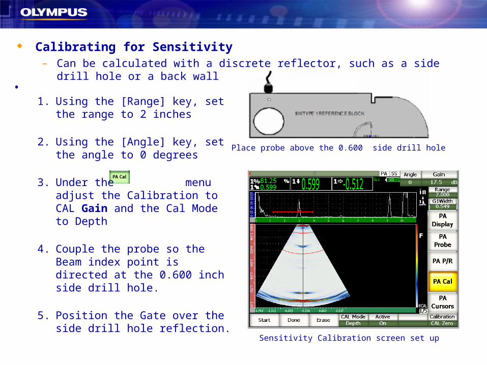
Calibrating for Sensitivity– Can be calculated with a discrete reflector, such as a side drill hole or a back wall
• Instructions1. Using the [Range] key, set the range
to 2 inches
2. Using the [Angle] key, set the angle to 0 degrees
3. Under the menu adjust the Calibration to CAL Gain and the Cal Mode to Depth
4. Couple the probe so the Beam index point is directed at the 0.600 inch side drill hole.
5. Position the Gate over the side drill hole reflection.
Place probe above the 0.600” side drill hole
Sensitivity Calibration screen set up

Calibrating for Sensitivity Cont.
6. Press the [Gate] key and the Right arrow key to access the G1Width parameter, and use the knob to adjust this value. ★ TIP: Gate start and width should be
positioned so that the measurement from the SDH can be acquired for every focal law
7. Press [Peak Mem] key to peak up the signal. (Should be centered to your probe)
8. Use the Auto XX% feature to increase the signal to the desired screen height.
9. Under the menu select Add.
Move probe back and forth to make sure G1Width is large enough
Select Add to being gain sensitivity data collection

Calibrating for Sensitivity
• Instructions
1. Move the probe over the side drilled hole to acquire un-calibrated thickness data across all focal laws
★ TIP: For the most accurate curve: Move the probe slowly. Use a guide to avoid skew. Make multiple passes over reflector
2. Press
to finish acquiring data and complete the Zero Offset Calibration.
★ NOTE: The wedge delay indication must not leave the gated region or become saturated for any focal law
★ NOTE: Use the Erase button to delete the curve and start again

• Verify calibrated distances and sensitivity by switching between 45, 60 and 70
degree focal laws.
Calibration Complete!
• Instrument will display 0CAL and TVG flags indicate that Zero and Gain calibrations have been performed and are being applied (Active).
Sensitivity calibration completed, may begin inspection