eor methods
TRANSCRIPT
EOR Methods Chandran Udumbasseri
Technical Consultant
Enhanced oil recovery (abbreviated EOR) is the implementation of various techniques for increasing the amount of crude oil that can be extracted from
an oil field. Enhanced oil recovery is also called improved oil recovery or tertiary recovery
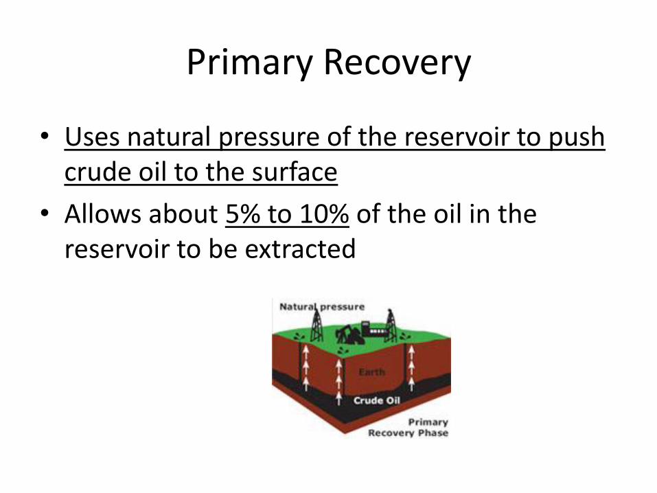
Primary Recovery
• Uses natural pressure of the reservoir to push crude oil to the surface
• Allows about 5% to 10% of the oil in the reservoir to be extracted
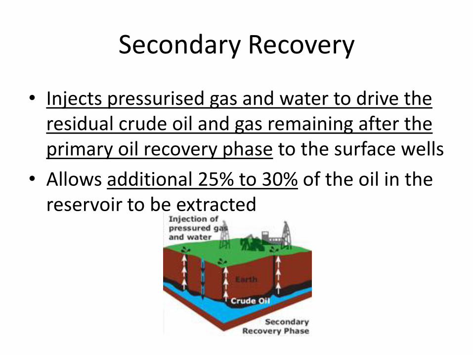
Secondary Recovery
• Injects pressurised gas and water to drive the residual crude oil and gas remaining after the primary oil recovery phase to the surface wells
• Allows additional 25% to 30% of the oil in the reservoir to be extracted
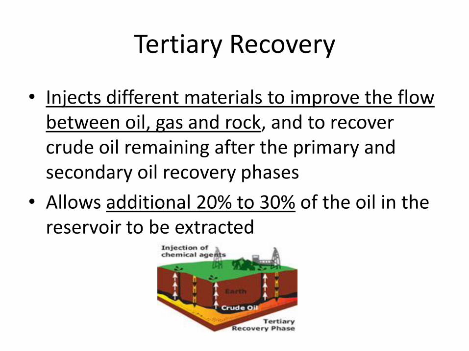
Tertiary Recovery
• Injects different materials to improve the flow between oil, gas and rock, and to recover crude oil remaining after the primary and secondary oil recovery phases
• Allows additional 20% to 30% of the oil in the reservoir to be extracted
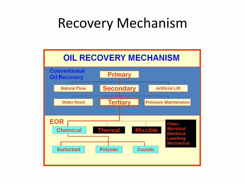
Recovery Mechanism
EOR classification • The processes in the EOR can be classified into 3
major categories. These methods have their own and mainly related to the type of oil remaining to be taken and reservoir characteristics (rock where the oil is)
• Chemical: 1) Surfactant flooding, 2) Micellar Polymer Flooding, 3) Polymer Flooding 4) Alkaline or Caustic Flooding.
• Thermal: 1) Steam Flooding 2) Fire Flooding • Miscible: 1) Carbon Dioxides Flooding, 2) Nitrogen
and Flue Gas Flooding, 3) Enriched Hydrocarbon Gas Flooding
EOR techniques
• Gas injection ( natural gas, CO2, Nitrogen)
• Thermal injection ( introduction of heat, cyclic steam injection, steam flooding)
• Chemical injection (surfactant flooding, polymer flooding, alkali flooding)
EOR-Thermal injection • Thermal injection, which involves the introduction of heat,
accounts for 40 percent of EOR production
• In thermal injection, various methods are used to heat the crude oil in the formation to reduce its viscosity and/or vaporize part of the oil and thus decrease the mobility ratio
• The increased heat reduces the surface tension and increases the permeability of the oil. The heated oil may also vaporize and then condense forming improved oil.
• Methods include cyclic steam injection, steam flooding and combustion.
• These methods improve the sweep efficiency and the displacement efficiency. Steam injection has been used commercially
EOR-water flooding -reservoir disadvantageous
• In secondary recovery water flooding used to drive oil to the production hole.
• But oil recovery in this flooding process is not high enough due to following reasons :
– reservoir heterogeneity
– problems related to the well sitting and spacing
– unfavorable mobility ratio
EOR-application criteria • Before applying EOR the following factors should be
considered:
– Depth
– Viscosity
– Permeability
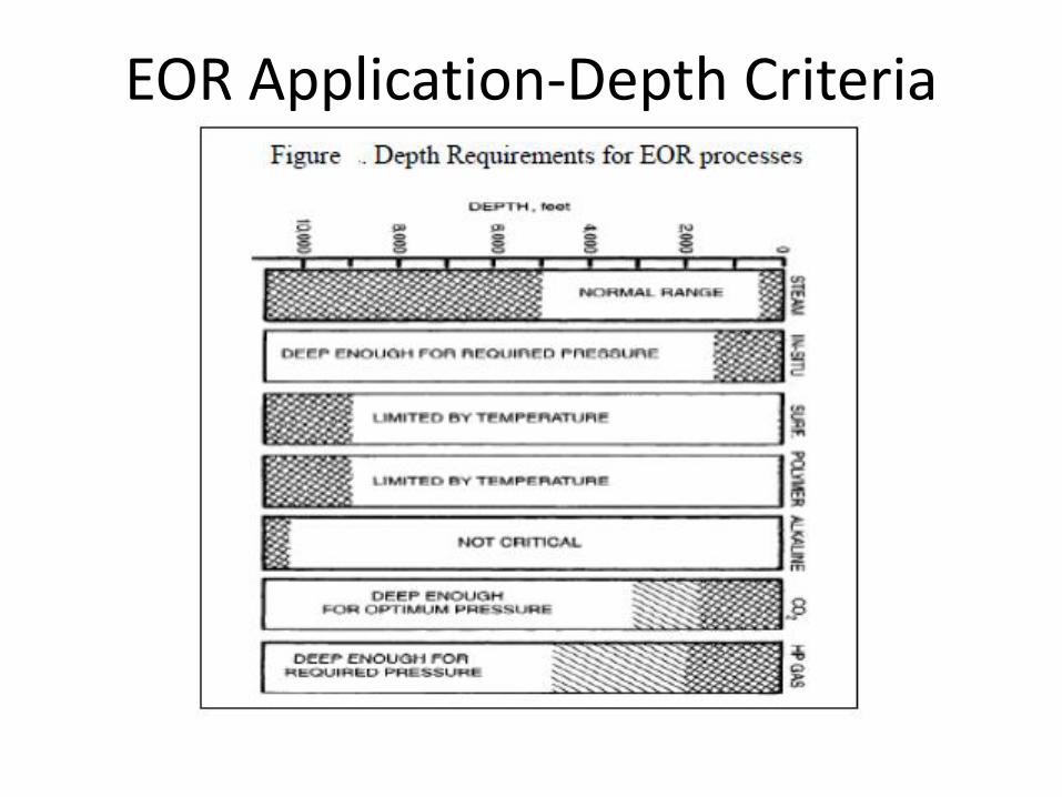
EOR Application-Depth Criteria
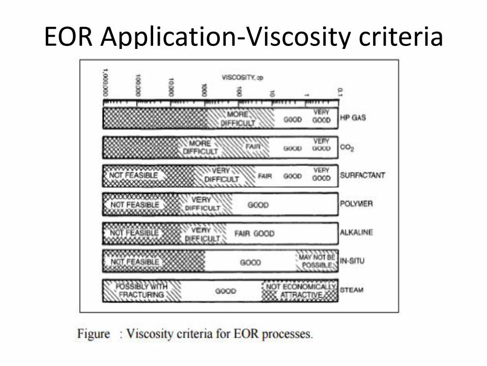
EOR Application-Viscosity criteria
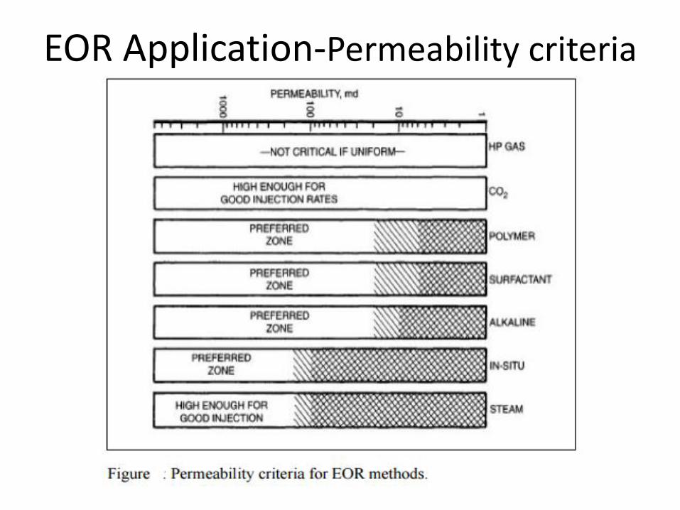
EOR Application-Permeability criteria
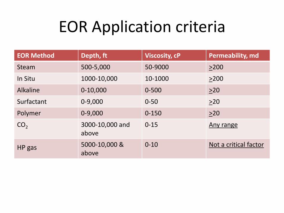
EOR Application criteria
EOR Method Depth, ft Viscosity, cP Permeability, md
Steam 500-5,000 50-9000 >200
In Situ 1000-10,000 10-1000 >200
Alkaline 0-10,000 0-500 >20
Surfactant 0-9,000 0-50 >20
Polymer 0-9,000 0-150 >20
CO2 3000-10,000 and above
0-15 Any range
HP gas 5000-10,000 & above
0-10 Not a critical factor

Thermal Flooding
• Thermal flooding is much easy to begin. After Primary and secondary production, the reservoirs contain heavy, low-API crude oils is usually a small fraction of the initial oil in place. This is due to the very thick and viscous nature of these oils making it difficult to migrate to production wells
• The viscosity of crude oil decreases in considerable magnitude with increase of temperature in the region 100oF to 200oF
Thermal flooding-steam stimulation
• The temperature of a reservoir can be raised by
– Steam Cycling or Stimulation
– Steam Drive
– In situ Combustion.
• Thermal flooding was the first in EOR processes.
• Most of the oil that has been produced by EOR methods to date has been as a result of thermal processes.
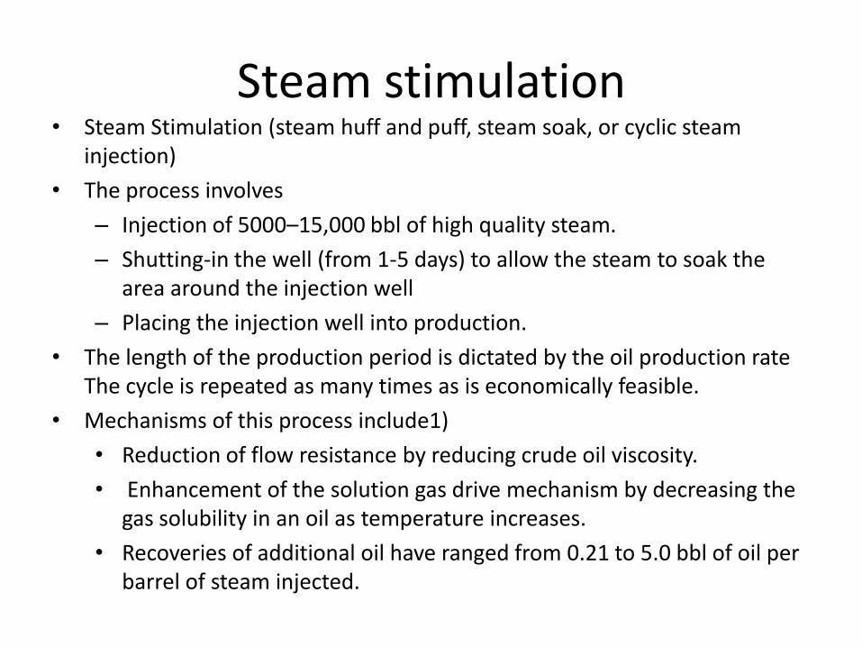
Steam stimulation • Steam Stimulation (steam huff and puff, steam soak, or cyclic steam
injection)
• The process involves
– Injection of 5000–15,000 bbl of high quality steam.
– Shutting-in the well (from 1-5 days) to allow the steam to soak the area around the injection well
– Placing the injection well into production.
• The length of the production period is dictated by the oil production rate The cycle is repeated as many times as is economically feasible.
• Mechanisms of this process include1)
• Reduction of flow resistance by reducing crude oil viscosity.
• Enhancement of the solution gas drive mechanism by decreasing the gas solubility in an oil as temperature increases.
• Recoveries of additional oil have ranged from 0.21 to 5.0 bbl of oil per barrel of steam injected.
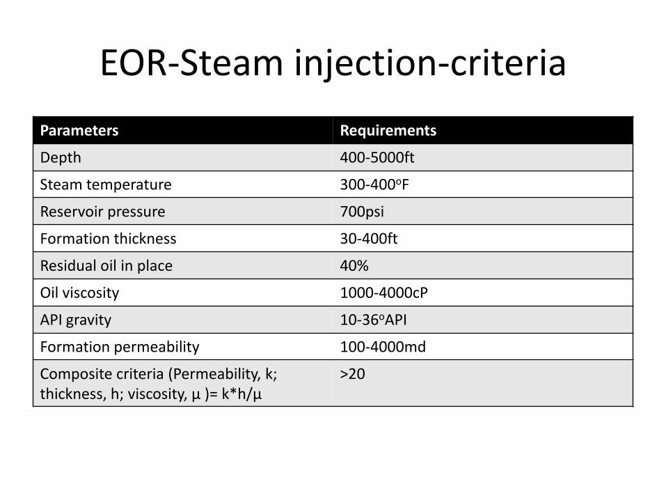
EOR-Steam injection-criteria
Parameters Requirements
Depth 400-5000ft
Steam temperature 300-400oF
Reservoir pressure 700psi
Formation thickness 30-400ft
Residual oil in place 40%
Oil viscosity 1000-4000cP
API gravity 10-36oAPI
Formation permeability 100-4000md
Composite criteria (Permeability, k; thickness, h; viscosity, µ )= k*h/µ
>20
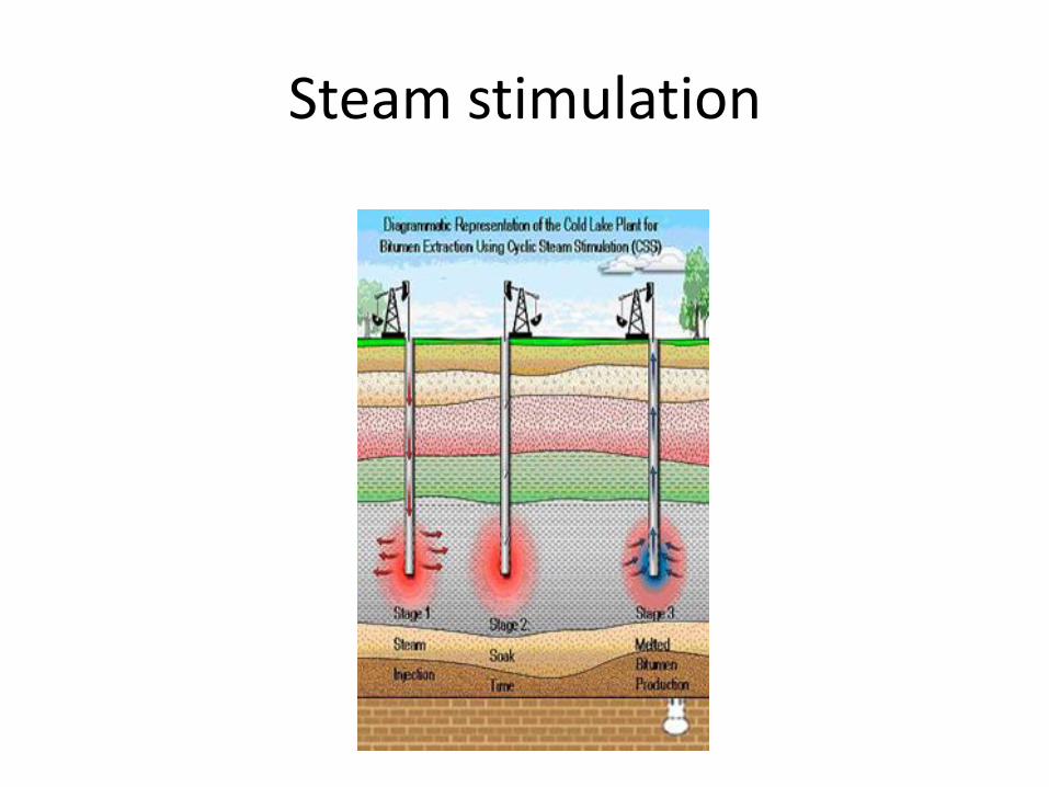
Steam stimulation
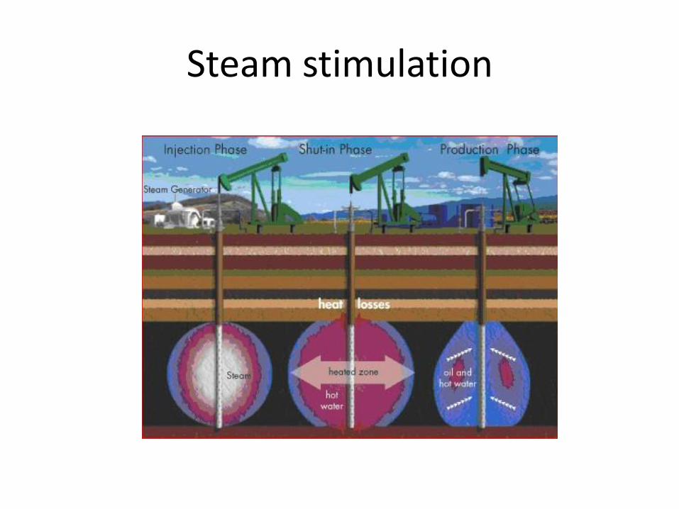
Steam stimulation
Steam drive • It is like a conventional water flood.- Steam is injected into
several injection wells while the oil is produced from other wells. (diff. from steam stimulation)
• Some thermal energy is lost in heating the formation rock and water
• The steam moves through the reservoir and comes in contact with cold oil, rock, and water.
• As the steam comes in contact with the cold environment, it condenses and a hot water bank is formed. This hot water bank acts as a water flood and pushes additional oil to the
producing wells.
Steam drive
• Mechanisms of this process
– include thermal expansion of the crude oil,
– viscosity reduction of the crude oil,
– changes in surface forces as the reservoi rtemperature increases,
– and steam distillation of the lighter portions of the crudeoil.
• This application is limited due to loss of heat energy. In deep wells, steam will be converted to liquid water
• Oil recoveries have ranged from 0.3 to 0.6 bbl of oil per barrel of steam injected.
• More expensive than steam stimulation.
In situ combustion • Forward dry combustion process
– Ignition of crude oil downhole.
– Injection of steam of oxygen enriched air
– Propagation of flame front through the reservoir heating oil.
– Heat loss
• Wet combustion process – -Beginning as a dry process
– Once flame front is established, the oxygen stream is replaced by water.
– Water meets hot zone left by combustion front,
– turns into steam, and aids the displacement of oil.-
– Usage of otherwise wasted energy
• Not all crude oils are amenable to the combustion process.-Heavy components must be enough in crude oil to serve as the fuel source for the combustion, so low API gravity oil is required.
• As the heavy components in the oil are combusted, lighter components as well as flue gases are formed. These gases are produced with the oil and raise the effective API gravity of the produced oil.
EOR-Natural Gas injection • Sometimes known as cycling, gas injection can entail re-
injection of produced natural gas. As the pressure drops in a natural gas field, the condensate separates from the dry gas in the reservoir. The condensate liquids block the pores within the reservoir, making extraction practically impossible.
• Cycling is used to prevent the condensate from separating from the natural gas in the reservoir. In this process, the natural gas liquids (condensate) are stripped from the gas on the surface after it has been produced from the reservoir, and the dry gas is then re-injected into the reservoir through injection wells. Again, this helps to maintain pressure in the reservoir while also preventing the separation within the hydrocarbon.
EOR-Gas injection
• Additionally, gas injection can serve as an economical way to dispose of uneconomical gas production on an oil reservoir.
• In the past, low levels of natural gas that were produced from oil fields were flared or burned off,
• This practice is discouraged in some countries by environmental regulations
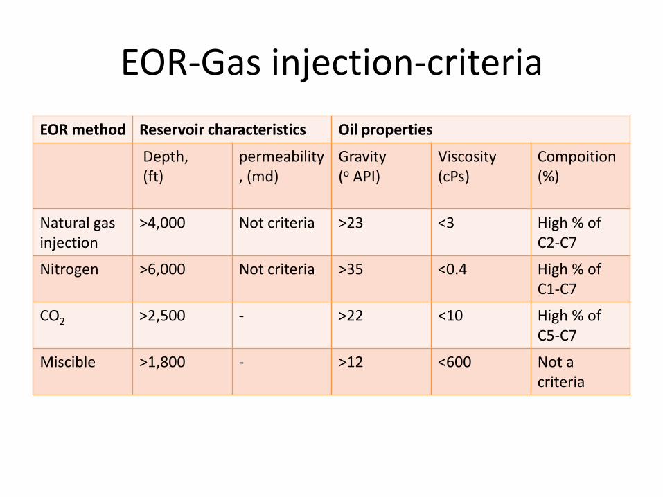
EOR-Gas injection-criteria
EOR method Reservoir characteristics Oil properties
Depth, (ft)
permeability, (md)
Gravity (o API)
Viscosity (cPs)
Compoition (%)
Natural gas injection
>4,000 Not criteria >23 <3 High % of C2-C7
Nitrogen >6,000 Not criteria >35 <0.4 High % of C1-C7
CO2 >2,500 - >22 <10 High % of C5-C7
Miscible >1,800 - >12 <600 Not a criteria

EOR-Gas injection advantageous
Nitrogen CO2 Flue gas
•sou
rce
•Produced from air by cryogenic separation •Available from 95-99%
•No natural source •Captured from flue gas of coal power plant
From combustion
•Pro
pe
rties
Inert and non corrosive-no need of corrosion inhibitor
Existing injection system may be used
Available with <10ppm O2
No need for biocide
Corrosive-need special corrosion inhibitors /corrosion resistant infra structure
Plugging due to asphaltene precipitation
CO2 removal from production is costly
Only very slightly miscible with crude
Corrosive SOX and NOX
presence O2 to be removed CO2 to be
removed which is costly

EOR-Nitrogen gas -advantageous
Gas injected Nitrogen CO2 Natural gas
Composite gas
Flue gas
Molecular weight 28.01 44.01 16.46 23.43 30.93
Compression factor, z 1.0184 0.6888 0.9151 0.7029 0.9959
Density (lb/cu ft) 6.00 13.93 3.92 6.45 6.77
Volume, MMscfd 1200 1774 1336 1543 1227
Viscosity, cPs 0.0299 0.0243 0.0154 0.0173 0.0231
Compression requirements, hp
500,500 665,500 528,000 578,600 510,400
Flow, million lbs/day 88.57 205.73 57.95 95.26 100.00
Price,$/mscf 0.23-0.56 1.00-1.25 2.1-2.2 1.23-1.50 0.55-0.82

EOR-Nitrogen flooding • The following conditions should be met for applying nitrogen
flooding: – The reservoir oil must be rich in ethane through hexane (C2-C6) or
lighter hydrocarbons. These crudes are characterized as "light oils" having an API gravity higher than 35 degrees.
– The oil should have a high formation-volume factor – the capability of absorbing added gas under reservoir conditions.
– The oil should be under-saturated or low in methane (C1).
– The reservoir should be at least 5,000 feet deep to withstand the high injection pressure (in excess of 5,000 psi) necessary for the oil to attain miscibility with nitrogen without fracturing the producing formation.
• Nitrogen can be separated from air by cryogenic methods. So there is unlimited source for this gas.
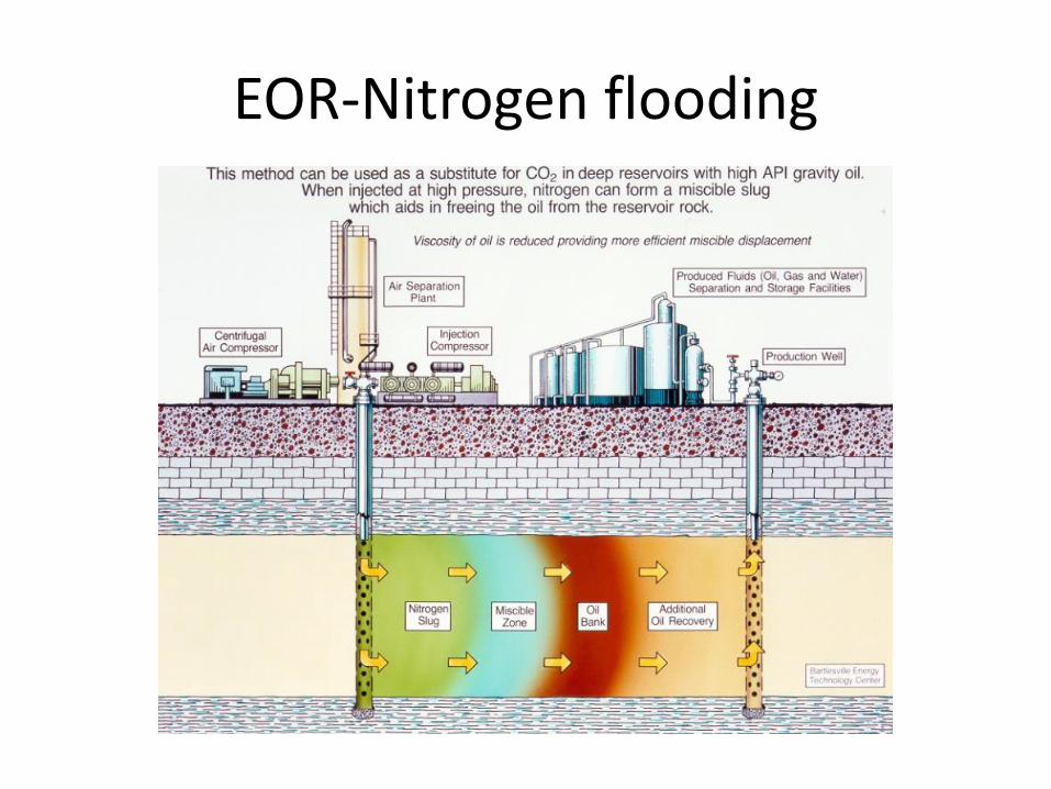
EOR-Nitrogen flooding • When nitrogen is injected into a reservoir, it forms a miscible front
by vaporizing some of the lighter components from the oil.
• Natural gas enriched nitrogen front moves away from the injection wells, contacting new oil and vaporizing more components, thereby enriching itself still further.
• The leading edge of this gas front becomes so enriched that it goes into solution, or becomes miscible, with the reservoir oil. At this time, the interface between the oil and gas disappears, and the fluids blend as one.
• Continued injection of nitrogen pushes the miscible front through the reservoir, moving a bank of displaced oil toward production wells.
• Water slugs are injected alternately with the nitrogen to increase the sweep efficiency and oil recovery
EOR-Nitrogen flooding
EOR-CO2 injection • When a reservoir’s pressure is depleted through primary and
secondary production, carbon dioxide flooding can be an ideal tertiary recovery method
• It’s particularly effective in reservoirs deeper than 2,000ft., where CO2 will be in a supercritical state
• On injecting CO2 into the reservoir, it dissolves in oil, the oil swells and the viscosity of any hydrocarbon will be reduced and hence, it will be easier to sweep to the production well
• If the well is suitable for CO2 flooding, then the pressure is restored by water injection. Then CO2 is injected
• In these applications, between one-half and two-thirds of the injected CO2 returns with the produced oil.
EOR-CO2 injection • This is then usually re-injected into the reservoir to minimize
operating costs.
• Carbon dioxide as a solvent has the benefit of being more economical than other similarly miscible fluids such as propane and butane.
• Unless natural CO2 exists in the near area, it’s generally difficult to collect sufficient amounts of CO2 for industry use.
• Availability of CO2 from the flue gas of coal power plants makes CO2 injection method more economical
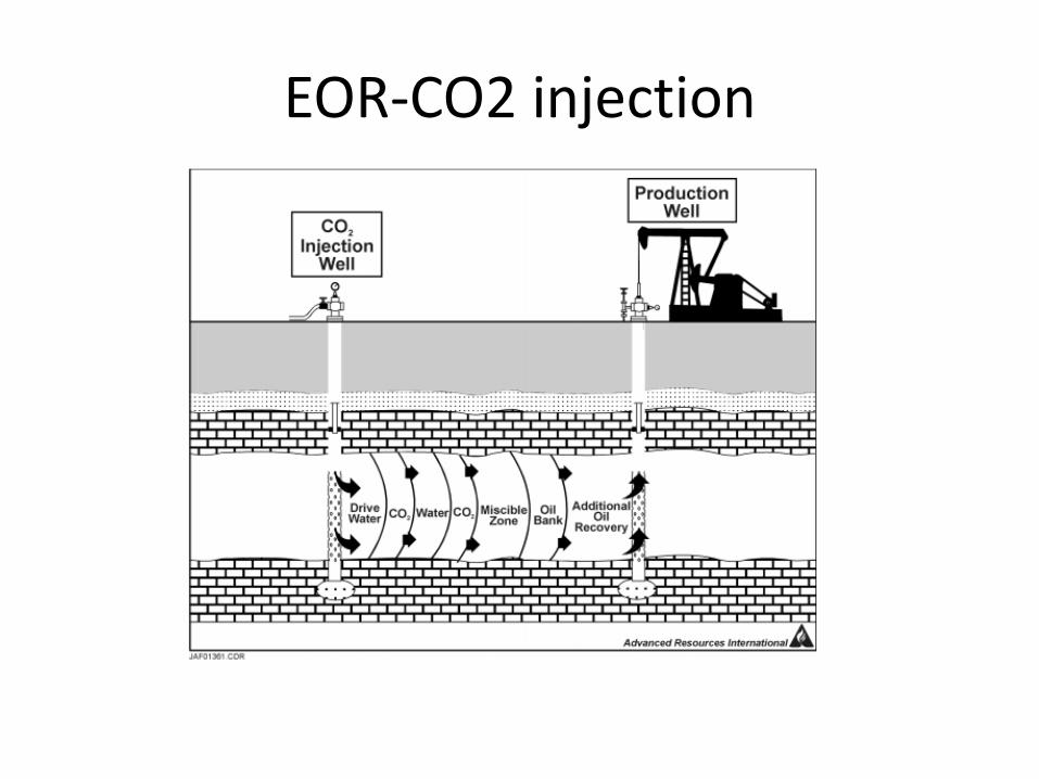
EOR-CO2 injection
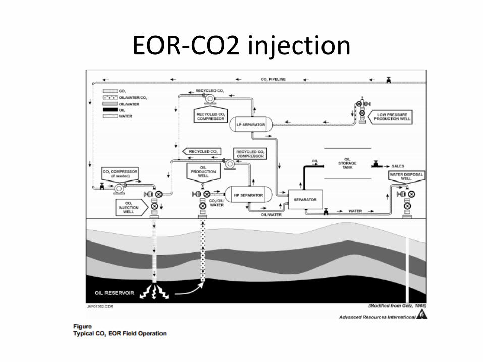
EOR-CO2 injection
EOR-Chemical flooding • The injection of various chemicals, usually as dilute solutions, have
been used to aid mobility and the reduction in surface tension.
• Injection of alkaline or caustic solutions into reservoirs with oil that has organic acids naturally occurring in the oil will result in the production of soap that may lower the interfacial tension enough to increase production.
• Injection of a dilute solution of a water soluble polymer to increase the viscosity of the injected water can increase the amount of oil recovered in some formations.
• Dilute solutions of surfactants such as petroleum sulfonates or biosurfactants such as rhamno lipids may be injected to lower the interfacial tension or capillary pressure that obstructs oil droplets from moving through a reservoir. Special formulations of oil, water and surfactant, microemulsions can be particularly effective in this.
EOR-chemical injection • Application of these methods is usually limited by the cost of
the chemicals and their adsorption and loss onto the rock of the oil containing formation
• Due to technical and economic considerations, chemical flooding, especially polymer flooding and ASP injection, is currently considered as the preferred tertiary oil recovery technique
• Main segments: – Chemical selected should not affect the physical & chemical properties
of the oilfield.
– After chemical flooding, crude oil is extracted, and the chemical waste, oil sludge and water in the residual liquid is then treated according to environmental protection standards. The treated water is recycled and reused for tertiary oil recovery and the oil sludge is disposed.
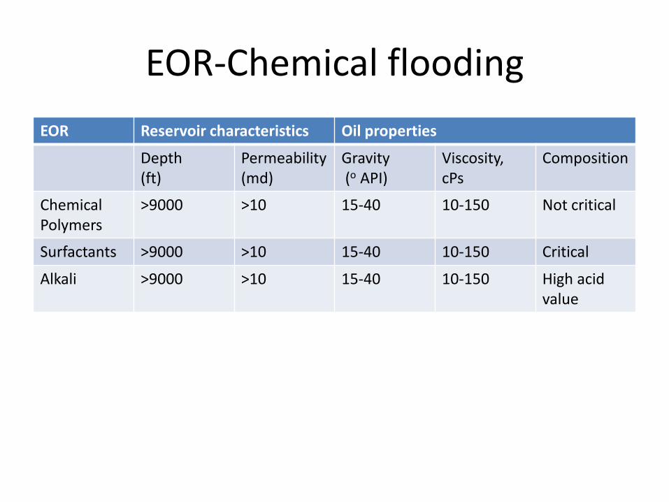
EOR-Chemical flooding
EOR Reservoir characteristics Oil properties
Depth (ft)
Permeability (md)
Gravity (o API)
Viscosity, cPs
Composition
Chemical Polymers
>9000 >10 15-40 10-150 Not critical
Surfactants >9000 >10 15-40 10-150 Critical
Alkali >9000 >10 15-40 10-150 High acid value
EOR-polymer flooding • In polymer flooding, the polymers used reduces the "surface tension"
between the oil and the oil-containing rock within the oil reservoir, "freeing" the trapped oil making it easier to flow to the production well(s).
• Polyacrylamide powder or "PAM" is a non-toxic powder that is having long-chain molecule is used in polymer flooding
• PAM makes the water "gel" greatly improving the production of oil. The water injected becomes more "viscous" or thick, much like a gel and is particularly beneficial in heavy oil recovery
• Benefits :
– Improved oil recovery
– Increased "sweep efficiency"
– Significantly less water required when compared with typical water-flooding & steam injection
– Superior EOR technology with "heavy oil" formations/reservoirs with low viscosity and where Steam Assisted Gravity Drainage (SAGD) is not suitable
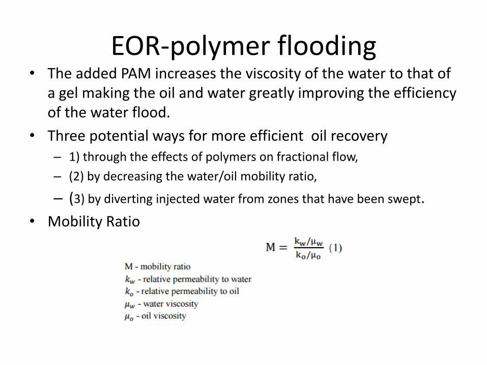
EOR-polymer flooding • The added PAM increases the viscosity of the water to that of
a gel making the oil and water greatly improving the efficiency of the water flood.
• Three potential ways for more efficient oil recovery – 1) through the effects of polymers on fractional flow,
– (2) by decreasing the water/oil mobility ratio,
– (3) by diverting injected water from zones that have been swept.
• Mobility Ratio
EOR-polymer flooding
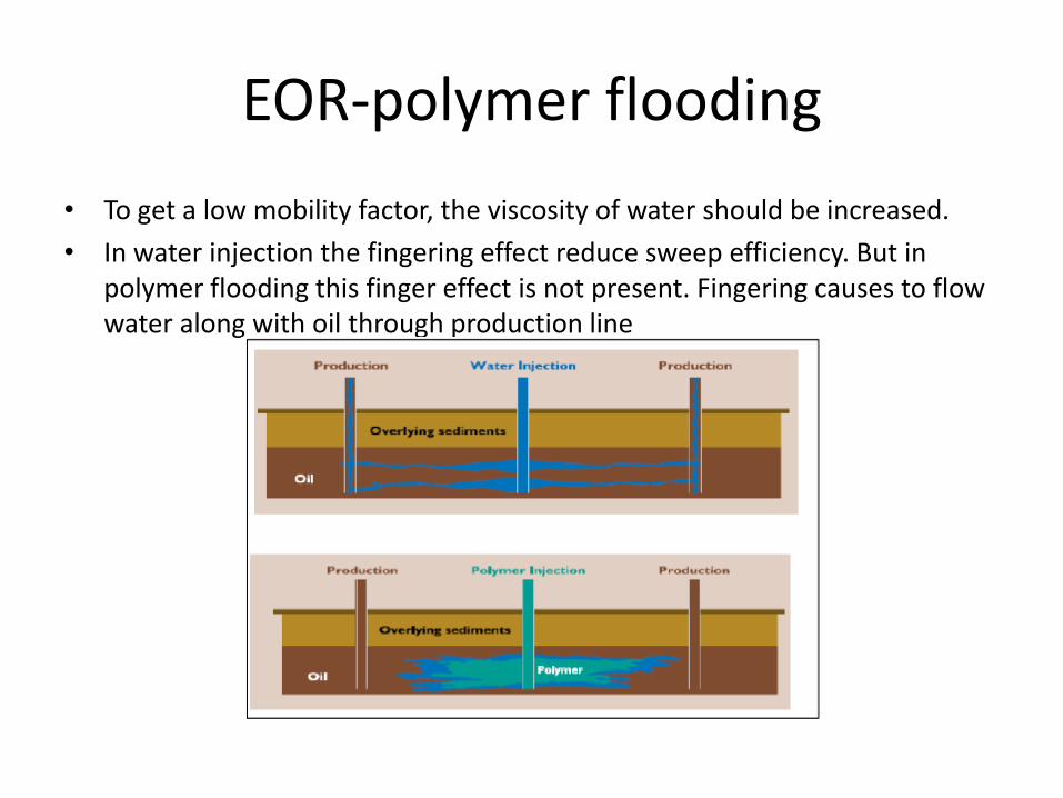
• To get a low mobility factor, the viscosity of water should be increased.
• In water injection the fingering effect reduce sweep efficiency. But in polymer flooding this finger effect is not present. Fingering causes to flow water along with oil through production line
EOR-Polymer flooding
• Permeability. Permeability is a key parameter for polymer flooding. According to studies, polymer flooding can be applied to field where permeability value is in the range of 20-2300mD (milli Darcy)
• Water salinity. The water salinity has a great effect on mobility, adsorption and permeability reduction features of polymers. – Adding salt to polymer solutions leads to the change in shape of molecules where its
shape transforms from inflated to spherical form.
– steep decrease in solution viscosity when 3% NaCl is added to polyacrylamides while in case of Xanthan polysaccharide, added salt shows a big effect.
EOR-Polymer flooding Criteria
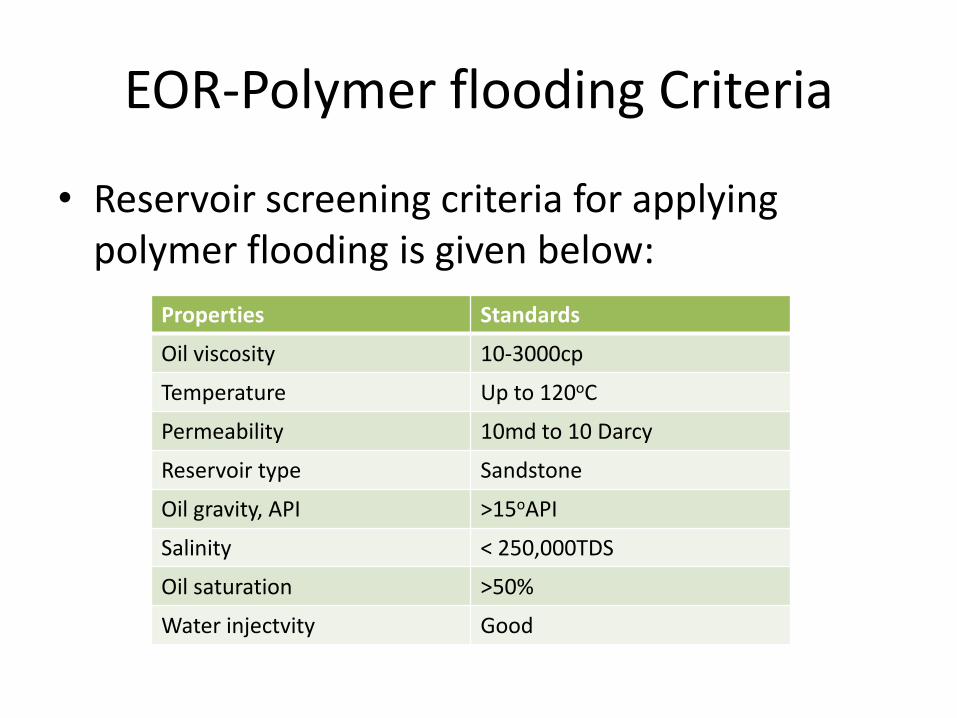
• Reservoir screening criteria for applying polymer flooding is given below:
Properties Standards
Oil viscosity 10-3000cp
Temperature Up to 120oC
Permeability 10md to 10 Darcy
Reservoir type Sandstone
Oil gravity, API >15oAPI
Salinity < 250,000TDS
Oil saturation >50%
Water injectvity Good
EOR-polymer flooding-selection
• For applying polymer flooding, the selection rules are:
– Find reservoirs with high mobility ratio and poor volumetric sweep efficiency
– Define if the properties of reservoir meet the screening criteria for polymer flooding.