entity-relationship modeling chapter - dssbooks
TRANSCRIPT

33
threeEntity-Relationship Modeling
chapterO V E R V I E W
3.1 Introduction
3.2 The Entity-Relationship Model
3.3 Entity
3.4 Attributes
3.5 Relationships
3.6 Degree of a Relationship
3.7 Cardinality of a Relationship
3.8 Unary Relationship
3.9 Binary Relationship
3.10 Ternary Relationships
3.11 Attributes of Relationships
3.12 Associative Entities
3.13 Weak Entity Types
3.14 Enhanced Entity-Relationship Modeling
3.15 Superclass, Subclass, and Relationships
3.16 Generalization and Specialization Process
3.17 Participation and Disjoint Constraints
3.18 Superclass/Subclass Hierarchy
3.19 Case Study: Conceptual Design for University Database
3.20 In-Class Assignment
3.21 Summary
3.22 Exercises
C H A P T E R
ch03_4770 4/4/07 12:09 PM Page 33

3.1 IntroductionIn Chapter 2, we introduced data models. A data model is an integrated collection of conceptsthat represents real world objects, events, and their relationships. We also briefly discussed twotypes of data models: object-based data models and relation-based data models. It is a commonpractice in database design to develop an object-based model first and then to systematicallyconvert the model into a relation-based model, which is more suitable for database implemen-tation. In this chapter, we will focus on conceptual database design using object-based models.In Chapter 4, we will discuss the relational data models.
The three most popular object-based models discussed in database literature are the entity-relationship model, the functional model, and the object-oriented model. The entity-relationshipmodel has emerged as one of the most popular techniques in the design of databases due to itsinherent advantages. The entity-relationship (E-R) model is easy to learn, yet powerful enoughto model complex, real-world scenarios. We have therefore chosen the E-R model for databasedesign discussion.
3.1.1 Topics
This chapter discusses the following topics:
■ Entities, attributes, and relationships in entity-relationship diagram.■ Degree of relationships: unary, binary, and ternary relationships.■ Cardinality of relationships: one-to-one relationships, one-to-many relationships,
many-to-many relationships.■ Associative and weak entity types.■ Enhanced entity-relationship diagram: generalization and specialization process, and
participation and disjoint constraints.
3.2 The Entity-Relationship ModelAn entity-relationship model describes data in terms of the following:
1. Entities2. Relationship between entities3. Attributes of entities
We graphically display an E-R model using an entity-relationship diagram (or E-R dia-gram) like the sample in Figure 3.1. While this figure may seem to be confusing at first glance,its meaning should become very clear by the end of this chapter.
We will now discuss the components of an E-R diagram in detail.
34 CHAPTER 3 ■ Entity-Relationship Modeling
ch03_4770 4/4/07 12:09 PM Page 34

3.3 EntityAn entity is an object that exists and which is distinguishable from other objects. An entity canbe a person, a place, an object, an event, or a concept about which an organization wishes tomaintain data. The following are some examples of entities:
Person: STUDENT, EMPLOYEE, CLIENT
Object: COUCH, AIRPLANE, MACHINE
Place: CITY, NATIONAL PARK, ROOM, WAREHOUSE
Event: WAR, MARRIAGE, LEASE
Concept: PROJECT, ACCOUNT, COURSE
It is important to understand the distinction between an entity type, an entity instance, andan entity set. An entity type defines a collection of entities that have same attributes. An entityinstance is a single item in this collection. An entity set is a set of entity instances. The follow-ing example will clarify this distinction: STUDENT is an entity type; a student with ID number555-55-5555 is an entity instance; and a collection of all students is an entity set.
In the E-R diagram, we assign a name to each entity type. When assigning names to entitytypes, we follow certain naming conventions. An entity name should be a concise singular nounthat captures the unique characteristics of the entity type. An E-R diagram depicts an entity typeusing a rectangle with the name of the entity inside (see Figure 3.2).
SECTION 3.3 ■ Entity 35
Submits
CUSTOMER
UsedIn
Requests
Supplies
Includes
Sends SUPPLIER
ITEM
ORDER PRODUCT
SHIPMENT
Figure 3.1 Example of an E-R diagram.
ch03_4770 4/4/07 12:09 PM Page 35

3.4 AttributesWe represent an entity with a set of attributes. An attribute is a property or characteristic of anentity type that is of interest to an organization. Some attributes of common entity types includethe following:
STUDENT = {Student ID, SSN, Name, Address, Phone, Email, DOB}
ORDER = {Order ID, Date of Order, Amount of Order}
ACCOUNT = {Account Number, Account Type, Date Opened, Balance}
CITY = {City Name, State, Population}
We use the following conventions while naming attributes:
1. Each word in a name starts with an uppercase letter followed by lower case letters.2. If an attribute name contains two or more words, the first letter of each subsequent
word is also in uppercase, unless it is an article or preposition, such as “a,” “the,” “of,”or “about” (see Figure 3.3).
36 CHAPTER 3 ■ Entity-Relationship Modeling
PERSON STUDENT EMPLOYEE
Figure 3.2 The entity representation in an E-R diagram.
STUDENT
StudentID
Name
DateofBirth
Major Age
Address
First
Last
Middle
Street
City Zip
State
Language
Figure 3.3 Attributes of the STUDENT entity type.
ch03_4770 4/4/07 12:09 PM Page 36

E-R diagrams depict an attribute inside an ellipse and connect the ellipse with a line to theassociated entity type. Figure 3.3 illustrates some of the possible attributes in an E-R diagram forthe entity STUDENT.
Notice that not all of the attributes in Figure 3.3 are marked in the same way. There are ac-tually several types of attributes featured in this figure. These include: simple, composite, single-valued, multi-valued, stored, and derived attributes. In the following subsections, we discuss thedistinctions between these types of attributes.
3.4.1 Simple and Composite Attributes
A simple or an atomic attribute, such as City or State, cannot be further divided into smallercomponents. A composite attribute, however, can be divided into smaller subparts in whicheach subpart represents an independent attribute. Name and Address are the only composite at-tributes in Figure 3.3. All other attributes, even those that are subcategories of Name and Ad-dress, are simple attributes. The figure also presents the notation that depicts a compositeattribute.
3.4.2 Single-Valued and Multi-Valued Attributes
Most attributes have a single value for an entity instance; such attributes are called single-valuedattributes. A multi-valued attribute, on the other hand, may have more than one value for anentity instance. Figure 3.3 features one multi-valued attribute, Languages, which stores thenames of the languages that a student speaks. Since a student may speak several languages, it isa multi-valued attribute. All other attributes of the STUDENT entity type are single-valued at-tributes. For example, a student has only one date of birth and one student identification num-ber. In the E-R diagram, we denote a multi-valued attribute with a double-lined ellipse. Notethat in a multi-valued attribute, we always use a double-lined ellipse, regardless of the numberof values.
3.4.3 Stored and Derived Attributes
The value of a derived attribute can be determined by analyzing other attributes. For example,in Figure 3.3 Age is a derived attribute because its value can be derived from the current date andthe attribute DateofBirth. An attribute whose value cannot be derived from the values of otherattributes is called a stored attribute. As we will learn, a derived attribute Age is not stored in thedatabase. Derived attributes are depicted in the E-R diagram with a dashed ellipse.
3.4.4 Key Attribute
A key attribute (or identifier) is a single attribute or a combination of attributes that uniquelyidentify an individual instance of an entity type. No two instances within an entity set can havethe same key attribute value. For the STUDENT entity shown in Figure 3.3, StudentID is the keyattribute since each student identification number is unique. Name, by contrast, cannot be anidentifier because two students can have the same name. We underline key attributes in an E-Rdiagram (also see Figure 3.4).
Sometimes no single attribute can uniquely identify an instance of an entity type. However,in these circumstances, we identify a set of attributes that, when combined, is unique for eachentity instance. In this case the key attribute, also known as composite key, is not a simple at-tribute, but a composite attribute that uniquely identifies each entity instance.
SECTION 3.4 ■ Attributes 37
ch03_4770 4/4/07 12:09 PM Page 37

A composite key must be minimal in the sense that no subset of a composite key can formthe key of the entity instance. For example, if a composite key has four attributes, A1 to A4, thenany subset, say A2, A4 or A2, A3 (or any of 16 combinations), should not form a key for anentity. In other words, we need all attributes, A1–A4, to identify each instance of an entityuniquely. In the E-R diagram, we underline each attribute in the composite key.
For example, consider the CITY entity type (see Figure 3.5). This category includes, poten-tially, all the cities in the United States. Notice that none of the attributes (i.e. Name, State orPopulation) can serve as a key attribute since there are many cities in each state and two citiescould possibly have the same name or population. However, the composite attribute {Name,State} is a valid key attribute for the CITY entity as no two cities within a state can have the samename.
An entity can have more than one attribute that qualifies to be an identifier. For the entityshown in Figure 3.6, each of the attributes Name, StateAbbr, and UnionOrder (the order inwhich the state entered the union of the United States) can be an identifier. In this case, it is amatter of preference as to which attribute is made an identifier or key attribute.
38 CHAPTER 3 ■ Entity-Relationship Modeling
StudentID
Name
Address
STUDENT
Figure 3.4 The key attribute.
Name
State
Population
CITY
Figure 3.5 The composite key attribute.
ch03_4770 4/4/07 12:09 PM Page 38

3.5 RelationshipsEntities in an organization do not exist in isolation but are related to each other. Students takecourses and each STUDENT entity is related to the COURSE entity. Faculty members teachcourses and each FACULTY entity is also related to the COURSE entity. Consequently, theSTUDENT entity is related to the FACULTY entity through the COURSE entity. E-R diagramscan also illustrate relationships between entities.
We define a relationship as an association among several entities. Consider, for example, anassociation between customers of a bank. If customer Williams has a bank account number 523,then the quality of ownership constitutes a relationship instance that associates the CUS-TOMER instance Williams with the ACCOUNT instance 523. We can think of the relationshipinstance as a verb that links a subject and an object: customer Williams has an account; studentJohn registers for a course; professor Smith teaches a course. A relationship set is a grouping ofall matching relationship instances, and the term relationship type refers to the relationship be-tween entity types. For example, Figure 3.7 illustrates a relationship set between the CUSTOMERand the ACCOUNT instances.
In an E-R diagram, we represent relationship types with diamond-shaped boxes connectedby straight lines to the rectangles that represent participating entity types. A relationship type isa given name that is displayed in this diamond-shaped box and typically takes the form of a
SECTION 3.5 ■ Relationships 39
StateAbbr
Name
PopulationUnionOrder
Bird
STATE
Figure 3.6 An example of more than one key attribute.
DefinitionAn entity is an object that exists and that is distinguishable from other objects.
An attribute is a property or characteristic of an entity type that is of interest to an organization.
A relationship is an association among several entities.
ch03_4770 4/4/07 12:09 PM Page 39

3.6 Degree of a RelationshipThe number of entity sets that participate in a relationship is called the degree of relationship.For example, the degree of the relationship featured in Figure 3.8 is two because CUSTOMERand ACCOUNT are two separate entity types that participate in the relationship. The threemost common degrees of a relationship in a database are unary (degree 1), binary (degree 2),and ternary (degree 3). We will briefly define these degrees and then explore each kind of rela-tionship in detail in subsequent sections.
Let E1, E2, . . . , En denote n entity sets and let R be the relationship. The degree of therelationship can also be expressed as follows:
Unary Relationship A unary relationship R is an association between two instances of thesame entity type (i.e., R ∈ E1 × E1). For example, two students are roommates and stay togetherin an apartment. Because they share the same address, a unary relationship exists between themfor the attribute Address in Figure 3.3.
40 CHAPTER 3 ■ Entity-Relationship Modeling
Wilson
Spears
Williams
White
Li
George
Mohan
Becker
032-11-385
045-22-258
135-56-637
321-21-769
185-67-485
232-98-506
413-18-237
687-57-017
Gainesville
Live oak
Alachua
Ocala
Ocala
Gainesville
Palatka
Alachua
102
345
638
921
718
523
881
256
5,163
5,600
1,100
3,300
1,800
3,500
900
356
313
285
409
536
1,200
6,700
1,500
9,800
4,700
2,000
918 7,200
CUSTOMER
ACCOUNT
Figure 3.7 The relationship set between the CUSTOMER and ACCOUNT entities.
present tense verb or verb phrase that describes the relationship. An E-R diagram may depict arelationship as the following example of the relationship between the entities CUSTOMER andACCOUNT does:
ch03_4770 4/4/07 12:09 PM Page 40

Binary Relationship A binary relationship R is an association between two instances of twodifferent entity types (i.e., R ∈ E1 × E2). For example, in a university, a binary relationship existsbetween a student (STUDENT entity) and an instructor (FACULTY entity) of a single class; aninstructor teaches a student.
Ternary Relationship A ternary relationship R is an association between three instances ofthree different entity types (i.e., R ∈ E1 × E2 × E3). For example, consider a student using cer-tain equipment for a project. In this case, the STUDENT, PROJECT, and EQUIPMENT entitytypes relate to each other with ternary relationships: a student checks out equipment for a project.
3.7 Cardinality of a RelationshipThe term cardinal number refers to the number used in counting. An ordinal number, by con-trast, emphasizes the order of a number (1st, 7th, etc.). When we say cardinality of a relation-ship, we mean the ability to count the number of entities involved in that relationship. Forexample, if the entity types A and B are connected by a relationship, then the maximum cardi-nality represents the maximum number of instances of entity B that can be associated with anyinstance of entity A.
However, we don’t need to assign a number value for every level of connection in a rela-tionship. In fact, the term maximum cardinality refers to only two possible values: one or many.While this may seem to be too simple, the division between one and many allows us to catego-rize all of the permutations possible in any relationship. The maximum cardinality value of a re-lationship, then, allows us to define the four types of relationships possible between entity typesA and B. Figure 3.9 illustrates these types of relationships.
One-to-One Relationship In a one-to-one relationship, at most one instance of entity B canbe associated with a given instance of entity A and vice versa.
One-to-Many Relationship In a one-to-many relationship, many instances of entity B can beassociated with a given instance of entity A. However, only one instance of entity A can be asso-ciated with a given instance of entity B. For example, while a customer of a company can makemany orders, an order can only be related to a single customer.
SECTION 3.7 ■ Cardinality of a Relationship 41
HasCUSTOMER ACCOUNT
Figure 3.8 The relationship between CUSTOMER and ACCOUNT entities in an E-R diagram.
ch03_4770 4/4/07 12:09 PM Page 41

Many-to-Many Relationship In a many-to-many relationship, many instances of entity Acan be associated with a given instance of entity B, and, likewise, many instances of entity B canbe associated with a given instance of entity A. For example, a machine may have different parts,while each individual part may be used in different machines.
Representing Relationship Types Figure 3.10 displays how we represent different relation-ship types in an E-R diagram. An entity on the one side of the relationship is represented by avertical line, “I,” which intersects the line connecting the entity and the relationship. Entities onthe many side of a relationship are designated by a crowfoot as depicted in Figure 3.10.
42 CHAPTER 3 ■ Entity-Relationship Modeling
b1
b2
b3
b4
b5
b6
a1
a2
a3
a4
a5
a6
b1
b2
b3
b4
b5
b6
a1
a2
a3
a4
a5
a6
b1
b2
b3
b4
b5
b6
a1
a2
a3
a4
a5
a6
b1
b2
b3
b4
b5
b6
a1
a2
a3
a4
a5
a6
B A B A B A B
One-to-One One-to-Many Many-to-One Many-to-Many
A
Figure 3.9 The four types of relationships between entity types A and B.
One-to-One One-to-Many
Many-to-One Many-to-Many
RA B RA B
RA B RA B
Figure 3.10 The relationship types based on maximum cardinality.
ch03_4770 4/4/07 12:09 PM Page 42

We will now discuss the minimum cardinality of a relationship. The minimum cardinalitybetween two entity types A and B is defined as the minimum number of instances of entity B thatmust be associated with each instance of entity A. In an E-R diagram, we allow the minimum car-dinality to take two values: zero or one. If the minimum cardinality is zero, we say that entitytype B is an optional participant in the relationship; otherwise, it is a mandatory participant. Anoptional relationship is represented by an “O” and mandatory relationship is represented by “|”in an E-R diagram.
Figure 3.11 shows the four possibilities of the minimum cardinality of a relationship be-tween two entity types A and B. Figure 3.11(a) depicts a situation in which no minimum cardi-nality constraints exist between the instances of entities A and B, meaning both entities A and Bare optional participants in the relationship. Figure 3.11(b) illustrates a situation in which eachinstance of entity B must be associated with at least one instance of entity A, but no associationis required for an instance of entity A. Figure 3.11(c) illustrates a situation in which each instanceof entity A must be associated with at least one instance of entity B, but no association is requiredfor an instance of entity B. Finally, Figure 3.11(d) illustrates a situation in which each instanceof entity A and B must be associated with at least one instance of entity B and A, respectively.
An E-R diagram displays both the maximum and the minimum cardinalities of the rela-tionships between two entities. Since there are four basic possibilities of maximum cardinalitiesand four possibilities of minimum cardinalities between two entities, there are 16 types of rela-tionships possible between two entities in terms of cardinality. We will see several examples ofthese relationships while studying unary, binary, and ternary relationships.
SECTION 3.7 ■ Cardinality of a Relationship 43
(a) (b)
(d)
RA B
RA B RA B
RA B
(c)
Figure 3.11 The relationship types based on minimum cardinality.
DefinitionThe number (unary, binary, or ternary) of entity sets that participate in a relationship is called the degree of relationship.
The cardinality of relationship represents the minimum/maximum number of instances ofentity B that must/can be associated with any instance of entity A.
ch03_4770 4/4/07 12:09 PM Page 43

3.8 Unary RelationshipAs we mentioned in Section 3.5, a unary relationship (R ∈ E1 × E1) is an association between twoentities of the same entity type. Figure 3.12(a) displays the E-R diagram of a unary relationshipIsMarriedTo. Whenever two people in the entity type PERSON get married, the relationship in-stance IsMarriedTo is created. The Date of marriage is an attribute of this relationship. Since aperson can only be married to one other person, marriage is a one-to-one relationship. Fur-thermore, since a person can be unmarried, the minimum cardinality of the IsMarriedTo rela-tionship is zero.
Figure 3.12(b) depicts several relationship instances of this relationship type. Each rela-tionship instance (r1, r2, r3, and r4) connects two instances in PERSON. The lines allow us to
44 CHAPTER 3 ■ Entity-Relationship Modeling
IsMarriedToPERSON Date
p1
p2
p3
p4
p5
p6
p12
p7
p8
p9
p10
p11
r1
r2
r3
r4
PERSON
IsMarriedTo
Figure 3.12 The unary one-to-one relationship.
(a)
(b)
ch03_4770 4/4/07 12:09 PM Page 44

read relationships between entity instances. For example, r1 suggests that person p1 is marriedto person p5, and so forth.
Figure 3.13(a) illustrates another example of a unary relationship, expressed by the rela-tionship instance Supervises. This relationship instance exists whenever an employee supervisesanother employee. The relationship Supervises is a one-to-many relationship since an employercan supervise many employees but a supervisee can have only one supervisor. The mini-mum cardinality for supervising is zero (an employee may not supervise anyone) but theminimum cardinality of being supervised is one (every employee must be supervised).
Figure 3.13(b) shows several relationship instances of this relationship type. Each relation-ship instance (r1, r2, r3, and r4) connects two entity instances in EMPLOYEE; these are the su-pervisor instance and the supervisee instance. For example, r2 suggests that employee e3supervises employee e7, and so forth.
SECTION 3.8 ■ Unary Relationship 45
(a)
(b)
SupervisesEmployee
e1
e2
e3
e4
e5
e6
e12
e7
e8
e9
e10
e11
r1
r2
r3
r4
Figure 3.13 The unary one-to-many relationship.
ch03_4770 4/4/07 12:09 PM Page 45
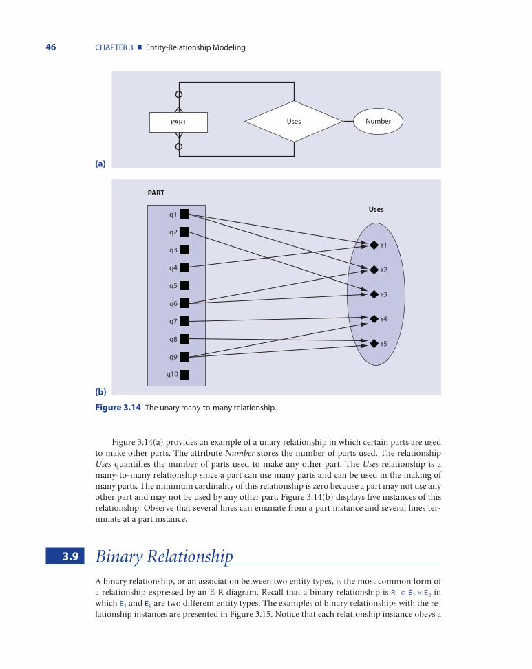
Figure 3.14(a) provides an example of a unary relationship in which certain parts are usedto make other parts. The attribute Number stores the number of parts used. The relationshipUses quantifies the number of parts used to make any other part. The Uses relationship is amany-to-many relationship since a part can use many parts and can be used in the making ofmany parts. The minimum cardinality of this relationship is zero because a part may not use anyother part and may not be used by any other part. Figure 3.14(b) displays five instances of thisrelationship. Observe that several lines can emanate from a part instance and several lines ter-minate at a part instance.
3.9 Binary RelationshipA binary relationship, or an association between two entity types, is the most common form ofa relationship expressed by an E-R diagram. Recall that a binary relationship is R ∈ E1 × E2 inwhich E1 and E2 are two different entity types. The examples of binary relationships with the re-lationship instances are presented in Figure 3.15. Notice that each relationship instance obeys a
46 CHAPTER 3 ■ Entity-Relationship Modeling
UsesPART Number
q1
q2
q3
q4
q5
q6
q7
q8
q9
q10
r1
r2
r3
r4
r5
PART
Uses
Figure 3.14 The unary many-to-many relationship.
(a)
(b)
ch03_4770 4/4/07 12:09 PM Page 46

basic characteristic of the binary relationships; in other words, each relationship instance is con-nected to exactly two entity instances of different entity types.
By applying what we have learned earlier in this chapter, we should be able to determine thecardinalities of these relationships quite easily. The relationship in Figure 3.15(a) is a one-to-onerelationship since we assume that an employee can manage at most one department and eachdepartment is managed by at most one employee. The minimum cardinality can be determined
SECTION 3.9 ■ Binary Relationship 47
ManagesEMPLOYEE DEPARTMENT
r1
r2
r3
r4
r5
EMPLOYEE DEPARTMENTManages
e1
e2
e3
e4
e5
e6
e7
e8
d1
d2
d3
d4
d5
Figure 3.15 (a) and (b): Binary one-to-one relationships; (c) and (d): Binary one-to-many relation-ships; (e) and (f): Binary many-many relationships.
(a)
PlacesCUSTOMER
DateOfOrder
ORDER
(c)
(b)
(continues)
ch03_4770 4/4/07 12:09 PM Page 47

48 CHAPTER 3 ■ Entity-Relationship Modeling
CUSTOMER ORDERPlaces
r1
r2
r3
r4
r5
r6
r7
c1
c2
c3
c4
c5
o1
o2
o3
o4
o5
o6
o7
Registers
Grade
COURSESTUDENT
(d)
STUDENT COURSERegisters
r1
r2
r3
r4
r5
r6
r7
r8
s1
s2
s3
s4
s5
s6
a1
a2
a3
a4
(f)
(e)
Figure 3.15 (continued)
ch03_4770 4/4/07 12:09 PM Page 48

SECTION 3.10 ■ Ternary Relationships 49
since each department must be managed by an employee, but not all employees manage de-partments. For example, while some of the employees in Figure 3.15(b), such as e2, e4, and e6,do not manage a department, every department is managed by an employee.
The binary one-to-many relationship represented in Figure 3.15(c) features a slightly dif-ferent arrangement. While a customer can place several orders or may choose not to order at all,each order must be placed by exactly one customer. Figure 3.15(d) shows us that, while eachorder is made by a single customer, not all customers place orders. However, Figure 3.15(d) dif-fers from Figure 3.15(b) in that a single customer may place any number of orders; while the firstcustomer places three orders, and the fifth customer places only two, both transactions representa maximum cardinality of many.
Finally, Figure 3.15(e) and (f) illustrates a many-to-many relationship, featuring a mini-mum cardinality of zero and a maximum cardinality of many. In other words, each student canparticipate in many activities, a single activity, or no activity at all. Conversely, any number ofstudents, from many to none, can participate in a given activity.
3.10 Ternary RelationshipsRecall that a ternary relationship R is a relationship among instances of three different entitytypes, E1, E2, and E3 (R ∈ E1 × E2 × E3). Each instance of the ternary relationship R requires the par-ticipation of an instance from each of the entity types E1, E2, and E3. See Figure 3.16 for examplesof ternary relationships.
The examples in Figure 3.16(a) and (b) reveal the possible relationships associated with acompetition for classical musicians. Let’s suppose that at this competition, musicians performindividually and in small groups for judges who rate the performances. Each performance re-quires an artist, a composition, and a venue. Observe that each relationship instance, Performs,connects an entity instance of MUSICIAN, COMPOSITION, and VENUE. Each relationship in-stance also has an attribute, Rating, that stores the average rating of the performance by a panelof judges. Similarly, in Figure 3.16(c), students use equipment to work on projects; each instanceof Uses involves an instance of STUDENT, PROJECT, and EQUIPMENT. If a student uses twopieces of equipment to work on a project, there are two instances of the relationship Uses. Acampus lab may use the attribute in this ternary relationship, the Date of use, to log the equip-ment usage.
Ternary relationships differ significantly from the other kinds of relationships that we haveexamined so far. It is important to remember that a ternary relationship is not equivalent totwo binary relationships. Suppose that we recognize this ternary relationship as a series of bi-nary relationships, such as ARTIST-CONCERT, ARTIST-COMPOSITION, and CONCERT-COMPOSITION. These three binary relationships can store data about the artists whoperformed at different concerts, the compositions performed by artists, and the compositionsperformed at different concerts; however, the relationships cannot store the compositions per-formed by an artist at a particular concert. Therefore, three binary relationships cannot encap-sulate the range of data stored by a single ternary relationship. A ternary relationship, though,can capture the data of three binary relationships.
Observe that the cardinalities of the relationships in Figure 3.16 are not expressed in the E-R diagrams. The cardinalities of a relationship are defined for a pair of entities; in a ternary re-lationship, there are three pairs of ternary relationships. We cannot express the cardinalities ofthese types of relationships in E-R diagrams. Instead, we can turn the ternary relationship intoan associative entity, a process that we will discuss in Section 3.12. This technique allows us todemonstrate the cardinalities of the entities within the associative entity.
ch03_4770 4/4/07 12:09 PM Page 49

50 CHAPTER 3 ■ Entity-Relationship Modeling
PerformsMUSICIAN
Rating
VENUE
COMPOSITION
ARTIST
COMPOSITION
Performs
a1
a2
a3
a4
a5
a6m1
m2
m3
m4
m5
CONCERT
m6
r1
r2
r3
r4
r5c2
c3
c5
c6
c7
c1
c4
Figure 3.16 Examples of ternary relationships.
(a)
(b)
(continues)
ch03_4770 4/4/07 12:09 PM Page 50

3.11 Attributes of RelationshipsWe have already discussed examples of E-R diagrams that reveal attributes stemming off rela-tionships. Recall Figure 3.15(c), for example. In that E-R diagram, the attribute DateofOrder col-lects data for the relationship CUSTOMER places ORDER. Attributes on relationships are likeattributes on entity types we have seen so far. An attribute on a relationship stores informationrelated to the relationship. In Figure 3.17, the attribute Quantity stores the number of compo-nents that make up an entity type ITEM. Note that the attribute Quantity stems from the rela-tionship and not from the entity.
SECTION 3110 ■ Attributes of Relationships 51
Figure 3.16 (continued)
(c)
UsesSTUDENT
Date
PROJECT
EQUIPMENT
(d)
STUDENT
EQUIPMENT
Uses
PROJECT
r1
r2
r3
r4
r1
r2
r3
r4
r5
e1
e2
e3
e4
e5p1
p2
p3
ch03_4770 4/4/07 12:09 PM Page 51

3.12 Associative EntitiesAn associative entity is an entity type that connects the instances of one or more entity typesand contains attributes particular to this association. Basically, an associative entity is a rela-tionship that has been turned into an entity because it meets one of the following conditions:
1. It is a many-to-many binary relationship2. It is a ternary relationship or a relationship of an even higher degree
The associative entity in an E-R diagram is represented by an entity box enclosing the dia-mond relationship symbol (see Figure 3.18). This symbol demonstrates that the entity is gener-ated from a relationship.
Consider, for example, the E-R diagram of the binary relationship illustrated in Figure3.18(a). When we convert this relationship into an associated entity, we get the E-R diagram inFigure 3.18(b). In the example, the relationship Participates is converted into an associated en-tity, ENROLLMENT. If the relationship has attributes, they become the attributes of the corre-sponding associative entity. DateJoined is an example of an attribute of a relationship turned intoan attribute of an associative entity in Figure 3.18(b).
Furthermore, recall that every entity in an E-R diagram must have an identifier. The iden-tifiers of two original entities together serve as a composite identifier of the associative entity. Inour example, the identifier of the entity ENROLLMENT is a composite attribute comprised ofthe identifiers of the STUDENT and ACTIVITY entities. Since a student can enroll in every ac-tivity but can only enroll once in any given activity, the composite attribute {StudentID, Activi-tyID} is a valid identifier for the associated entity ENROLLMENT.
Now that ENROLLMENT is a new entity in Figure 3.18(b), note that there is no relation-ship diamond on the line between the entity STUDENT and the associative entity ENROLL-MENT because the associative entity represents a relationship. Furthermore, the E-R diagram inFigure 3.18 (b) depicts the cardinalities. Each instance of the STUDENT entity is related to sev-eral instances of the ENROLLMENT entity; in fact, each instance of the STUDENT entity is re-lated to as many instances of the ENROLLMENT entity as the number of activities in which thestudent participates. Therefore, there is a one-to-many relationship between the STUDENT en-tity type and the ENROLLMENT entity type. Similarly, there is a one-to-many relationship be-tween the entity types ACTIVITY and ENROLLMENT because several students may enroll inone activity.
52 CHAPTER 3 ■ Entity-Relationship Modeling
ContainsITEM Quantity
Figure 3.17 An example of attributes of relationships.
ch03_4770 4/4/07 12:09 PM Page 52

Notice that when we convert a relationship into an associative entity, we change its namefrom a verb to a noun. Therefore, the relationship expressed by the verb participates in Figure3.18(a) becomes the associative entity represented by the noun enrollment in Figure 3.18(b).This grammatical distinction parallels the main reason for turning a relationship into an asso-ciative entity. A verb expresses an action, a process. However, once we want to count, record, oranalyze an instance of that process, we end up with a person, place, or thing. In short, by trans-forming a relationship into an associative entity, we can analyze and record a process in the sameway that we analyze and record a noun.
In Chapter 4, we make it clear why we can only turn a many-to-many relationship into anassociative entity. We convert a ternary relationship into an associative entity as it allows us toexpress the cardinalities of a relationship correctly. We will now consider another example of as-sociative entity converted from a ternary relationship.
The E-R diagram shown in Figure 3.19 is similar to the one we first observed in Figure 3.16.Here, we convert the ternary relationship instance Performs into the associative entity PER-FORMANCE. We change the verb performs, an action not necessarily related to a specific event,to performance, a noun that expresses an event that can be recorded, counted, and analyzed.Observe that the identifier of the associated entity PERFORMANCE is comprised of the unionof the identifiers of the entities involved in the ternary relationship. One of the most important
SECTION 3.12 ■ Associative Entities 53
(a)
ACTIVITY
FeesActivityID
STUDENT
StudentID
Name Address
DateJoined
Participates
(b)
ENROLLMENT
DateJoined
StudentID
ActivityIDName
Address
StudentID
STUDENT ACTIVITY
FeesActivityID
Figure 3.18 (a) A many-to-many binary relationship; (b) A many-to-many binary relationship converted to anassociated entity.
ch03_4770 4/4/07 12:09 PM Page 53

characteristics of this arrangement is that each entity, ARTIST, VENUE, and COMPOSITION,has a one-to-many relationship (minimum cardinalities are omitted for clarity) with the associ-ated entity PERFORMANCE.
3.13 Weak Entity TypesEntity types can be classified into two categories: strong entity types and weak entity types. Astrong entity type exists independent of other entity types, while a weak entity type depends onanother entity type. Consider a student database that includes an entity STUDENT. Supposethat we also record data about each student’s dependents, such as a spouse or children, in thisdatabase. To do so, we must create the entity type DEPENDENT. The entity type DEPENDENTdoes not exist on its own and owes its existence to the STUDENT entity type. When students
54 CHAPTER 3 ■ Entity-Relationship Modeling
(a)
COMPOSITION
NameComposition ID
ARTIST
Rating
VENUE LocationConcert ID
NameArtistID
Performs
(b)
COMPOSITION
NameComposition ID
ARTIST
VENUE LocationConcert ID
NameArtistID
PERFORMANCE
Rating Artist ID
CompositionConcert ID
Figure 3.19 (a) A ternary relationship; (b) A ternary relationship converting to an associated entity.
ch03_4770 4/4/07 12:09 PM Page 54

graduate and their records are removed from the STUDENT entity set, the records of their de-pendents are also removed from the DEPENDENT entity set. In the E-R diagram, a weak entityis indicated by a double-lined rectangle. The corresponding relationship diamond is alsodouble-lined.
The entity type on which a weak entity type depends is called the identifying owner (or sim-ply owner), and the relationship between a weak entity type and its owner is called an identify-ing relationship. In Figure 3.20, STUDENT is the owner and Has is the identifying relationship.For a weak entity, we define a partial key attribute that, when combined with the key attribute ofits owner, provides the full identifier for the weak entity. In Figure 3.20, for example, Depen-dentName is the partial identifying attribute. When we combine it with the StudentID, ituniquely identifies the dependent. Of course, in this example, we make an implicit assumptionthat people do not give the same name to more than one of their children.
SECTION 3.14 ■ Enhanced Entity-Relationship Modeling 55
DefinitionAn associative entity is an entity type that connects the instances of one or more entity typesand contains attributes particular to this association.
A strong entity type exists independent of other entity types, while a weak entity typedepends on another entity type.
Has
DateOfBirthDependentName
Student Name
Student IDAddress
DEPENDENT STUDENT
Figure 3.20 The weak entity in an E-R diagram.
3.14 Enhanced Entity-Relationship ModelingWe have illustrated the basic concepts of the entity-relationship model. These concepts are gen-erally adequate to design solutions for common business problems. However, since the early1980s, business database applications and database requirements have changed dramatically.Business relationships and business data have become much more complex as applications suchas multimedia systems, geographical information systems, and computer-aided engineeringhave gained prominence. These applications demand more complex database requirementsthan traditional applications, rendering the basic concepts of E-R modeling inadequate. As a
ch03_4770 4/4/07 12:09 PM Page 55

result, researchers in the ’80s enhanced the original E-R model to form the enhanced entity-relationship (EE-R) model.
In the remaining sections of this chapter, we will discuss the EE-R model by detailing su-perclass and subclass entities, the processes of specialization and generalization, and variousconstraints on these processes.
3.15 Superclass, Subclass, and RelationshipsRecall that we have defined an entity type as a collection of entities that share the same attributes.In this section, we will introduce two special types of entities: superclass and subclass. We willalso discuss the notations that allow us to include these special entities in a regular E-R diagramto create an enhanced entity-relationship (EE-R) diagram. We will also study superclass andsubclass relationships as well as the process of attribute inheritance associated with superclassand subclass entity types.
3.15.1 Superclass and Subclass
All the instances of an entity type share the same set of attributes, but each single attribute may notbe a required attribute of for each instance. For example, consider the PERSON entity type. Theentity PERSON includes all personnel in a university. Specifically, it includes students, staff, andfaculty members. The attributes of this entity, SSN, Address, Email, Salary, Class, GPA, and OfficePhone are depicted in Figure 3.21. Although all these attributes are common to the PERSON en-tity, attributes such as Class and GPA are not required for faculty instances of PERSON. At thesame time, the attribute Salary is required for staff and faculty but may not be relevant for students.
This distinction is important when we have a large number of instances for an entity type. Insuch a scenario, one or more attributes for each instance won’t have any valid value. In our exam-ple, each faculty instance will have no valid value for GPA and Class, and many student instanceswon’t have value for Salary, Rank, and Designation. As we will see in Chapter 4, having many re-dundant fields results in a data redundancy problem and degrades the database performance.
56 CHAPTER 3 ■ Entity-Relationship Modeling
PERSON
Name
EmailSSN
Address
BirthDate
Office Phone
Salary
Class
Designation
GPA
Rank
Figure 3.21 The E-R diagram for entity type PERSON.
ch03_4770 4/4/07 12:09 PM Page 56

One possible solution to this problem is to extend the E-R model to accurately represent thecomplex groupings that we encounter in everyday life. Let us begin our discussion by formallydefining superclass and subclass entity types.
A superclass is an entity type that has one or more distinct subgroups with unique attributes.For example, the entity type PERSON in Figure 3.22 is a superclass that includes faculty, staff, andstudents as its subgroups. The superclass features only those attributes that are common for all itssubgroups. For example, attributes of PERSON such as SSN, Name, Address, and Email are sharedby all its subgroups regardless of an individual’s position as student, faculty, or staff within theuniversity. The subgroups with unique attributes are defined as subclasses. The PERSON super-class thus has three subclasses: STUDENT, STAFF, and FACULTY. A subclass entity type STU-DENT has attributes of its superclass along with its own attributes such as Major, GPA, and Classthat uniquely identify the subclass. Figure 3.22 depicts a superclass and subclasses.
SECTION 3.15 ■ Superclass, Subclass, and Relationships 57
PERSON
FACULTY STAFF STUDENT
Name
SSN
Address
BirthDate
Salary
Rank
OfficePhoneSalary
Class
Designation
GPA
Figure 3.22 The enhanced E-R diagram for entity type PERSON.
Let us examine the formal notations used to represent a superclass and subclass. We repre-sent both superclass and subclass entity types with the usual rectangle notation of an entity type.A superclass is connected to a circle by a short line. This circle, in turn, is connected to each ofthe subclass entity types with another line. An optional U-shaped symbol on each line that con-nects subclass entity types to the circle indicates that a subclass is a subset of a superclass entitytype. This U-shaped symbol also indicates the direction of the superclass/subclass relationship.In that sense, it operates like an arrow pointing from the superclass to a subclass. Other nota-tions of basic E-R diagrams prevail (see Figure 3.23 for general layout).
ch03_4770 4/4/07 12:09 PM Page 57

There are several reasons for introducing superclass and subclasses into an E-R model.First, incorporating a superclass and subclasses maintains the cleanliness of the structure andimproves the conceptual flow. Second, it adds familiar semantic information to an E-R diagram.We consider using subtypes if the following conditions apply:
1. Certain attributes apply to some, but not all, instances of an entity type.2. An instance of a subtype participates in a relationship unique to that relationship (see
Figure 3.24).
58 CHAPTER 3 ■ Entity-Relationship Modeling
SUPERCLASS
SUBCLASS 1 SUBCLASS 2 SUBCLASS N
Att. of subclass1
Generalentity type
Specializedentity type
Attributescommon to all
entities
Att. ofsubclass2
Figure 3.23 The notations for superclass and subclass relationships.
DefinitionThe Enhanced Entity-Relationships (EE-R) model is a revised E-R model that extends the originalE-R model and supports additional semantic concepts by providing new modeling constructs.
A superclass is an entity type that has one or more distinct sub groups with unique attributes.
A subclass is an entity type that shares common attributes or relationships distinct from othersubclasses.
3.15.2 Attribute Inheritance and Subclass Relationships
Attribute Inheritance is the property by which subclass entities inherit attributes of the super-class. The subclass entity type is an entity type in itself with a set of attributes and relationships.In addition to its own attributes, a subclass entity inherits all the attributes of its superclass. Forexample, the STUDENT subclass has attributes such as MajorDept, Class, and GPA. It also in-
ch03_4770 4/4/07 12:09 PM Page 58
herits all the attributes of the PERSON entity type. In other words, if Chris Alto is an instance ofthe STUDENT subclass, then he is necessarily an instance of the PERSON superclass as well.Chris Alto is a value for the Name attribute for the entity PERSON, and the STUDENT subclassinherits it from the PERSON. Note that Chris’s 4.0 GPA is an attribute of the STUDENT sub-class only. Thus, the identifier of a superclass is also inherited by all its subclasses and serves asan identifier for subclasses. Subclasses don’t need their own identifier. Thus, the relationship be-tween a superclass and subclass is always a one-to-one relationship (notations are usually ig-nored in an E-R diagram).
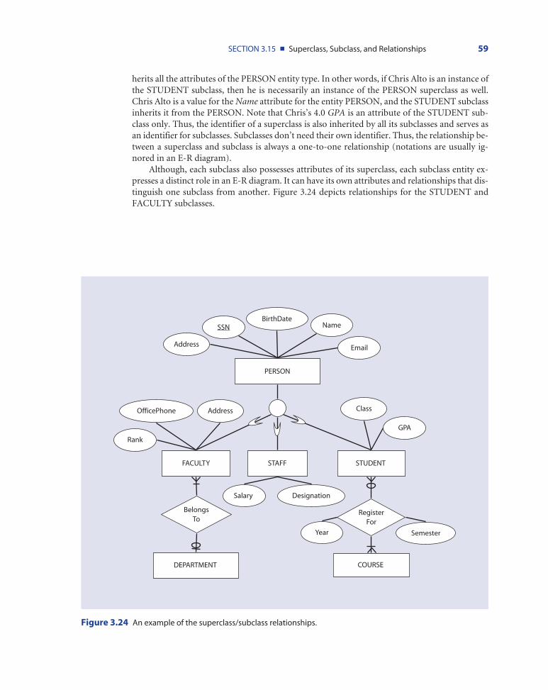
Although, each subclass also possesses attributes of its superclass, each subclass entity ex-presses a distinct role in an E-R diagram. It can have its own attributes and relationships that dis-tinguish one subclass from another. Figure 3.24 depicts relationships for the STUDENT andFACULTY subclasses.
SECTION 3.15 ■ Superclass, Subclass, and Relationships 59
PERSON
FACULTY STAFF STUDENT
Name
SSN
Address
BirthDate
Rank
AddressOfficePhone
Salary
Class
Designation
GPA
RegisterFor
BelongsTo
DEPARTMENT COURSE
Year Semester
Figure 3.24 An example of the superclass/subclass relationships.
ch03_4770 4/4/07 12:09 PM Page 59

3.16 Generalization and Specialization ProcessIn the previous section we described the superclass/subclass model. However, in the process ofmodeling a complex real-word scenario, it is important to recognize when superclass and sub-class entity types can be generated. The processes of specialization and generalization are used tofind such opportunities. These processes serve as conceptual models for the development ofsuperclass/subclass relationships.
3.16.1 Generalization
Generalization is the process of defining general entity types from a set of specialized entitytypes by identifying their common characteristics. In other words, this process minimizes thedifferences between entities by identifying a general entity type that features the common attrib-utes of specialized entities. Generalization is a bottom-up approach as it starts with the special-ized entity types (subclasses) and forms a generalized entity type (superclass).
For example, suppose that someone has given us the specialized entity types FACULTY,STAFF, and STUDENT, and we want to represent these entity types separately in the E-R modelas depicted in Figure 3.25(a). However, if we examine them closely, we can observe that anumber of attributes are common to all entity types, while others are specific to a particular en-tity. For example, FACULTY, STAFF, and STUDENT all share the attributes Name, SSN, BirthDate, Address, and Email. On the other hand, attributes such as GPA, Class, and MajorDept arespecific to the STUDENTS; OfficePhone is specific to FACULTY, and Designation is specific toSTAFF. Common attributes suggest that each of these three entity types is a form of a more gen-
60 CHAPTER 3 ■ Entity-Relationship Modeling
(continues)
Figure 3.25 (a) STAFF, FACULTY, and STUDENT entities before generalization; (b) PERSON superclass and FAC-ULTY, STAFF, and STUDENT subclasses after generalization.
(a)
FACULTY STAFF
STUDENT
Name
BirthDate
Rank
Salary
SSN
Address
OfficePhone
Salary
Class
Designation
GPA
SSN
Name
E mail
BirthDate
Address
Name
E mail
BirthDate
SSN
Address
ch03_4770 4/4/07 12:09 PM Page 60

eral entity type. This general entity type is simply a PERSON superclass entity with common at-tributes of three subclasses (see Figure 3.25(b)).
Thus, in the generalization process, we group specialized entity types to form one generalentity type and identify common attributes of specialized entities as attributes of a general en-tity type. The general entity type is a superclass of specialized entity types or subclasses.
3.16.2 Specialization
Specialization is the process of defining one or more subclasses of a superclass by identifying itsdistinguishing characteristics. Unlike generalization, specialization is thus a top-down approach.It starts with the general entity (superclass) and forms specialized entity types (subclasses) basedon specialized attributes or relationships specific to a subclass.
For example, consider Figure 3.26(a). LIBRARY ITEM is an entity type with several attrib-utes such as IdentificationNo, RecordingDate, Frequency, and Edition. After careful review ofthese items, it should become clear that some items such as books do not have values for attrib-utes such as Frequency, RecordingDate, and CourseNo, while Video CDs do not have an Authoror an Edition.
In addition, all items have common attributes such as IdentificationNo, Location, and Sub-ject. Someone creating a library database, then, could use the specialization process to identifysuperclass and subclass relationships. In this case, the original entity LIBRARY ITEM forms a su-perclass entity type made up of attributes shared by all items, while specialized items with dis-tinguishing attributes, such as BOOK, JOURNALS, and VIDEOCD, form subclasses.
SECTION 3.16 ■ Generalization and Specialization Process 61
(b)
PERSON
FACULTY STAFF STUDENT
Name
SSN
Address
BirthDate
Salary
Rank
OfficePhoneSalary ClassDesignation GPA
Figure 3.25 (continued)
ch03_4770 4/4/07 12:09 PM Page 61

62 CHAPTER 3 ■ Entity-Relationship Modeling
(a)
LIBRARY ITEM
Frequency
AuthorName
IdentificationNo
Edition
CourseNo
Location
RecordingDate
Subject CurrentIssue
(b)
BOOK JOURNAL VIDEOCD
Subject Location IdentificationNo
AuthorName Edition
Frequency
CourseNo
CurrentIssue
RecordDate
LIBRARY ITEM
Figure 3.26 (a) LIBRARY ITEM entity before specialization; (b) LIBRARY ITEM superclass and BOOK, JOURNAL, andVIDEOCD subclasses after specialization.
ch03_4770 4/4/07 12:09 PM Page 62

3.17 Participation and Disjoint ConstraintsSo far we have discussed superclass/subclass entity types, their relationships, and two processesto identify them. In this section, we will discuss constraints on superclass/subclass relationships.Specifically, we will introduce a participation constraint and a disjoint constraint. These con-straints are intuitive and help us manifest business rules and incorporate them into the designof an EE-R.
3.17.1 Participation Constraints
Participation constraints dictate whether each instance (member) of a superclass must partici-pate as an instance (member) of a subclass. A participation of superclass instance may bemandatory or optional in one or more subclasses. The mandatory constraint is also known as atotal participation (constraint) or total specialization rule, while an optional constraint is knownas a partial participation (constraint) or partial specialization rule.
Total Participation Rule In total participation, membership is mandatory. Each instance ofa superclass must be an instance of at least one subclass. For example, consider Figure 3.27.
SECTION 3.17 ■ Participation and Disjoint Contraints 63
DefinitionAttribute inheritance is the property by which subclass entities inherit values for all attributes of the superclass.
Generalization is the process of defining a general entity type from a set of specialized entitytypes by identifying their common characteristics.
Specialization is a process of defining one or more subclasses of a superclass by identifying their distinguishing characteristics.
GRADUATE UNDERGRAD
GPAName SSN
Degree Chair Class
STUDENT
Figure 3.27 An example of the total participation rule.
ch03_4770 4/4/07 12:09 PM Page 63

Every instance of the superclass STUDENT must be an instance of either the GRADUATE stu-dent or UNDERGRAD student subclass. That is, if John Doe is an instance of a STUDENT, thenJohn must be a graduate or undergraduate student. However, whether John Doe belongs to thegraduate, undergraduate, or both entity types is answered by the disjoint rule, which we will de-fine in a moment. We use a double line between the superclass entity type and the circle to rep-resent the total participation.
Partial Participation Rule Membership is optional in a partial participation. An instance ofa superclass does not have to be an instance of any of the subclasses. For example, consider Fig-ure 3.26. An instance of the LIBRARY ITEM superclass can be a member of BOOK, VIDEO CD,or JOURNALS; however it is not mandatory for an instance to belong to any of these subclasses.If the library item Newspaper is an instance of a superclass, it does not have to be included in oneof the subclasses; it can stay at the superclass level without having values for any subclass attrib-utes. We use a single line between the superclass entity type and the circle (the default notation)to represent partial participation.
3.17.2 Disjoint Constraints
Disjoint constraints define whether it is possible for an instance of a superclass to simultane-ously be a member of one or more subclasses. Disjoint constraints indicate whether a superclassinstance can be disjointed or overlap more than one subclass.
Disjoint Rule The disjoint rule states that if an instance of a superclass is a member of anysubclass, then it cannot be a member of more than one subtype (note that the participation rulewill dictate whether the instance is a member of a subclass or not). For example, consider Fig-ure 3.28. We put a constraint of disjoint rule to indicate that a student must be either a gradu-ate or an undergraduate student but cannot belong to both subclasses simultaneously. Weindicate the disjoint rule by putting a letter “D” in the joining circle of the superclass/subclass re-lationship (see Figure 3.28).
64 CHAPTER 3 ■ Entity-Relationship Modeling
GRADUATEGRADUATE UNDERGRADUNDERGRAD
GPAGPANameName SSNSSN
Degree Degree ChairChair ClassClass
DD
STUDENTSTUDENT
Figure 3.28 An example of the disjoint rule.
ch03_4770 4/4/07 12:09 PM Page 64

Overlap Rule The overlap rule states that if an instance of a superclass is a member of anysubclass, then it can be a member (overlap) of more than one subtype. For example, considerFigure 3.29. It reveals that an instance of a PERSON must be FACULTY, STAFF, a STUDENT,or any combination of these three. A work-study person would overlap, for example, the STAFFand STUDENT entities. We indicate the overlap rule by putting a letter “O” in the joining cir-cle of the superclass/subclass relationship.
3.17.3 Subclass Discriminators
The participation and disjoint constraints allow an instance of a superclass to be a member ofone or more subclasses. We keep track of membership using a special attribute of a superclass,a subclass discriminator. In other words, we put a discriminating attribute on a superclass thatcan record membership of superclass instances into one or more subclasses. Figure 3.30 providesan example of total participation with the disjoint rule. An instance of STUDENT item must bea member of exactly one subclass. For every instance of a superclass when it is assigned to eithersubclass, we record the membership in the StudentType attribute. For example, if John Doe is agraduate student, we assign a value, say “G,” to StudentType. If Monica Adams is an undergrad-uate student, we assign StudentType “U,” and so on.
There are two special cases with partial participation and overlap rules using a discriminat-ing attribute. If the participation is partial and an instance of a superclass does not participate inany subclasses, we assign NULL value to the discriminating attribute. If an overlap rule is in ef-fect and if an instance of a superclass participates in more than one subclass, we assign multiplevalues to the discriminating attribute. Thus, the discriminating attribute becomes a multi-valuedattribute under the overlap rule.
SECTION 3.17 ■ Participation and Disjoint Contraints 65
PERSON
FACULTY STAFF STUDENT
Sex
SSN
Address
BirthDate
Salary Address
OfficePhone
Salary ClassDesignation GPA
O
Figure 3.29 An example of the overlap rule.
ch03_4770 4/4/07 12:09 PM Page 65

3.18 Superclass/Subclass HierarchyA subclass type can have one or more subclasses. In other words, a subclass can act as superclassfor other entity types, resulting in a hierarchy of superclass and subclasses. A superclass/subclass hierarchy is a hierarchical structure of a superclass and its various subclasses in whicheach subclass has exactly one superclass. For example, we have discussed PERSON and STU-DENT superclass entity types. We put these two examples together in Figure 3.31 to create a hi-erarchical structure.
66 CHAPTER 3 ■ Entity-Relationship Modeling
GRADUATE UNDERGRAD
GPA
Name
SSN
Degree Chair Class
D
STUDENT
StudentType
Figure 3.30 StudentType subclass discriminator.
DefinitionParticipation constraints dictate whether each instance (member) of a superclass must partici-pate as an instance (member) of a subclass.
Disjoint constraints define whether it is possible for an instance of a superclass to simultane-ously be a member of one or more subclasses.
A superclass/subclass hierarchy is a hierarchical structure of a superclass and its various sub-classes in which each subclass has exactly one superclass.
ch03_4770 4/4/07 12:09 PM Page 66

PERSON is the superclass with FACULTY, STAFF, and STUDENT as its subclasses. The re-lationship is partial participation with overlap rules. The STUDENT subclass has its own sub-classes: GRADUATE student and UNDERGRAD student. Further, the GRADUATE subclassacts as a superclass for TA and RA subclasses; a graduate student can be a teaching assistant or aresearch assistant or both. Thus each level of a hierarchy can have its own set of entity types andrelationships to depict the organizational requirements.
SECTION 3.18 ■ Superclass./Subclass Hierarchy 67
PERSON
FACULTY STAFF STUDENT
Sex
SSN
Address
BirthDate
Salary Address
Office Phone
Salary
Class
Designation
GPA
GRADUATE UNDERGRAD
Degree Chair Class
TA RA
O
ProjectCourse
D
O
Figure 3.31 An example of a superclass/subclass hierarchy.
ch03_4770 4/4/07 12:09 PM Page 67

3.19 Case Study: Conceptual Design for University DatabaseIn this section, we illustrate the conceptual design for a university database in Figure 3.32
68 CHAPTER 3 ■ Entity-Relationship Modeling
DeptID
Phone
Address
Address
PERSON
D
STUDENTFACULTY
BelongsTo
Register
Teaches
SECTION
Has
COURSE
Offers
BelongsTo
COLLEGE
EmailPhone
NationalityName
SSN
Sex
Addres
Rank
JoinDateClass
Type
Name
Name
Phone
Name TextBook CourseID
CreditHours
Grade
StartDate
Semester
Year
SectionID
CapacityDEPARTMENT
CollegeID
Major
Figure 3.32 An EE-R diagram for the university database.
ch03_4770 4/4/07 12:09 PM Page 68

3.20 In-Class AssignmentConsider the following problem statement to draw an E-R diagram:
The annual Bolder Boulder is one of America’s top 10 km races. The race is held eachMemorial Day in Boulder, Colorado. This race attracts world-class runners as well ascasual joggers. It is a point-to-point race beginning at the Bank of Boulder at thenortheast corner of the city, winding throughout the city streets, and ending near thetown center in the University of Colorado’s football stadium.
The organizers record the following information for each race: the date of the race; the totalnumber of runners registered for the race (on-line pre-registration is possible); the actual num-ber of participants; the number of male runners; the number of female runners; the name of themale winner; the name of the female winner; the name of the male master (runner over the ageof 40) winner; and the name of the female master winner. In addition, the following informa-tion about each participant is recorded: social security number, name, birth date, gender, ad-dress, age, and certified personal record (PR) running times for a 10 km race.
SECTION 3.21 ■ Summary 69
3.21 Summary■ An entity type defines a collection of entities that
have the same attributes. An entity instance is asingle item in this collection, and an entity set is aset of entity instances.
■ An attribute is a property or characteristic of anentity type that is of interest to an organization.
■ Most attributes are single-valued, meaning theyhave a single value for an entity instance. A multi-valued attribute is an attribute that can take morethan one value for an entity instance.
■ A derived attribute is one whose value can be de-rived from other attributes.
■ A key attribute is an attribute or a combination ofseveral attributes that uniquely identify an individ-ual instance of an entity type.
■ The degree of the relationship is the number ofentity sets that participate in a relationship.
■ A unary relationship R is an association betweentwo instances of the same entity types.
■ A binary relationship R is an association betweentwo instances of two different entity types.
■ A ternary relationship R is an association betweenthree instances of three different entity types.
■ The maximum cardinality represents the maximumnumber of instances of any entity B that can beassociated with any instance of any entity A.
■ The minimum cardinality of a relationship betweenthe entity types A and B is the minimum numberof instances of entity B that must be associatedwith each instance of entity A.
■ An associative entity is an entity type that associatesthe instances of one or more entity types and con-tains attributes particular to this association.
■ A strong entity type exists independent of otherentity types. A weak entity type’s existence dependson another entity type.
■ The Enhanced Entity-Relationships (EE-R) model isa revised E-R model that extends the original E-Rmodel and supports additional semantic conceptsby providing new modeling constructs.
■ A superclass is an entity type that has one or moredistinct sub groups with unique attributes. Thesubgroups should be of importance to the organi-zation and are therefore necessarily represented ina data model.
■ A subclass is an entity type that shares commonattributes or relationships distinct from othersubclasses.
■ Attribute inheritance is the property by whichsubclass entities inherit values for all attributes ofthe superclass.
■ Generalization is the process of defining a generalentity type from a set of specialized entity types byidentifying their common characteristics.
■ Specialization is a process of defining one or moresubclasses of a superclass by identifying their dis-tinguishing characteristics.
■ Participation constraints dictate whether everyinstance of a superclass must participate as aninstance of a subclass. If it is mandatory for a
ch03_4770 4/4/07 12:09 PM Page 69

superclass instance to be a member of at least onesubclass, it is known as the total participation rule.When some instances of a superclass are free to notparticipate in any of the subclasses, it is referred toas the partial participation rule.
■ Disjoint constraints dictate whether it is possible foran instance of a superclass to be a member of oneor more subclasses simultaneously. The disjointrule states that if the instance of superclass is amember of a subclass, then it must belong to ex-
actly one subclass. The overlap rule states thatmembers of a subclass can belong to more thanone subclass.
■ A subclass discriminator is an attribute of a super-class that classifies its instance into the appropriatesubclass. The value of a discriminator determinesthe target subclass for an instance of a superclass.
■ A superclass/subclass hierarchy is a hierarchicalstructure of a superclass and subclasses whereineach subclass has exactly one superclass.
70 CHAPTER 3 ■ Entity-Relationship Modeling
3.22 Exercises3.22.1 Review Questions
1. Explain the following terms using an example:entity-relationship model, entity type, weakentity, attribute, key attribute, derived attribute,multi-valued attribute.
2. Explain, using an example (other than the onesdiscussed in the book), the contrast between thefollowing terms:
a. entity type; entity instance
b. strong entity type; weak entity type
c. simple attribute; composite attribute
d. stored attribute; derived attribute
3. Provide an example of multiple relationshipsbetween entities. Draw the E-R diagram.
4. Under what conditions is a relationship convertedto an associative entity type? Give an example.
5. Explain why we study the E-R model of a database.
6. A department in a university stores the informa-tion about its students and courses in a database.The administrative assistant manages the database.At the end of the semester, he prepares a reportabout each course. Is the E-R diagram correct? Ifnot, explain why and draw the correct diagram.
7. A veterinary doctor stores the information abouthis clients and their pets in a database. Completethe following E-R diagram.
8. Explain the term “degree of a relationship.”Provide a simple example for each of the threetypes of relationships described in this chapterand draw the corresponding E-R diagrams.
9. A university maintains a detailed database of itsstudent information. The following is the E-Rdiagram of entity STUDENT. Draw an alternativeE-R diagram for this database.
10. Discuss the reasons for choosing one of the at-tributes as an identifier of an entity type.
11. “Enhanced E-R diagrams provide more flexibilityin designing a database than E-R diagrams.”Support this statement with an example.
STUDENT
ID
Name Address
History
HasCLIENT PET
ClientID Name Name
STUDENT COURSE
PreparesSECRETARY REPORT
Summarizes
Takes
ch03_4770 4/4/07 12:09 PM Page 70

12. Using an example, define the following terms:subtype, subtype discriminator, disjoint rule,overlapping rule. Demonstrate how they relate toone another.
13. Using an example, explain the reasons why adatabase designer considers using subtype/super-type relationships.
14. The Admissions office in a university stores theinformation about the university entrance appli-cations in a database. In order to facilitate pro-cessing the applications, the office classifies theapplicants as freshman, transfer, graduate, andinternational students.
a. Draw the EE-R diagram of this database. Iden-tify a unique attribute for each entity subtype.
b. Add a subtype discriminator for each of thesubtypes of the entity APPLICANT.
15. Using an example, explain the difference betweenthe generalization rule and the specialization rule.
16. The Accounting department in a company keepsthe information about its employees in a data-base. The employees are classified as part-timeemployees, full-time employees, and interns.Interns are usually students who work with thecompany during the summers. Complete the EE-R diagram below by:
a. Adding a unique attribute (relationship) foreach entity subtype
b. Adding an attribute shared by all entities
c. Identifying whether the disjoint or overlaprule applies
d. Identifying whether the total specialization orpartial specialization rule applies
3.22.2 Hands-On Exercises
1. Savannah’s family has owned and operated a 640-acre farm for several generations. Since the busi-ness is growing, Savannah is considering buildinga database that would make it easier to managethe farm’s activities. She is considering the fol-lowing requirements for the database:
a. For each livestock classification group (forexample: cow, horse, etc.), Savannah keepstrack of each animal’s identification numberand classification.
b. For each crop, she records the crop identifica-tion number and the classification.
c. Savannah has recorded the yield of each cropclassification group during the last ten years.The records consist of the year, yield, sales,crop price, and amount of money earned.
d. Savannah has also recorded the yield of eachlivestock classification group during the lastten years. The records consist of the followinghistorical data: the year, the (historical) sellingprice per head, the number of livestock in theend of the year, the number of livestock soldduring a one-year period, and the totalamount of money earned.
Draw an E-R diagram for this application. Specifythe key attribute of each entity type.
2. The Coca Cola Company in Atlanta, Georgiaproduces a wide range of products that are deliv-ered to its worldwide clientele once a week. Thecompany stores information about its employees,products, and customers in a database that in-cludes the following set of tables:
a. The company records the following informa-tion about its customers: customer identifica-tion number, name, address, X (longitude)and Y (latitude) coordinates of their location,and the amount of time (in fractions of anhour) required making a stop at that location.
b. Each employee has an employee identificationnumber, name, address (which consists of acity, state, and zip code), gender, birth date,position in the company, wage earned perhour of regular time work, wage earned perhour of overtime work, number of depen-dents, and number of years worked for theCoca Cola Company.
c. Each product has a product identificationnumber, price, and number of units producedper day.
Products may be ordered by one or more cus-tomers, and a customer may order one or moreproducts. Furthermore, employees produce oneor more products, and a product may be pro-duced by exactly one employee. Draw an E-Rdiagram for the above description and add theminimum and maximum relationship cardinali-ties. Identify the key attributes for each entity andthe composite attributes.
3. Consider the database in Hands-On Exercise 2.Update the E-R diagram for the cases describedbelow. For each entity, identify the keyattribute(s).
SECTION 3.22 ■ Exercises 71
ch03_4770 4/4/07 12:09 PM Page 71

a. For tax purposes, the Coca Cola Companyextends the data kept for each employee toinclude additional information about theirdependents. This information consists of eachdependent’s name, birth date, and age.
b. The company has decided to record informa-tion about its suppliers and the rawmaterial(s) supplied by them. The followinginformation is recorded for each supplier: thesupplier identification number, the address,and the name of the contact person. The rawmaterial information consists of the raw mate-rial identification number and the material’sname.
c. The company keeps a fleet of vehicles to facili-tate the distribution of the products to thecustomers. Each vehicle has an identificationnumber, model, and capacity.
It should also be noted that employees use rawmaterials to produce one or more final products,which are delivered to the customer. A suppliersupplies many raw materials, but a particular rawmaterial is purchased from only one supplier. Itis not necessary to include all the attributes andcardinalities from the previous question. Just besure to include the entities to demonstrate therelationships and attributes for the new entities.
4. Again consider the database in Hands-On Exer-cise 2. The Coca Cola Company has a few plantsthat are distributed throughout Georgia. For eachplant, the following information is stored in thedatabase: a plant identification number, theaddress, and the X and Y coordinates of the plantlocation. Note that the inventory level, inventorycapacity, and quantity produced of a particularproduct differ by plant.
The systems of relationships that exist are asfollows. A plant may have one or more employ-ees, and an employee works in exactly one plant.Additionally, a plant produces one or more prod-ucts, and a product may be produced in one ormore plants. Also, an employee may contributeto one or more products, and a product is pro-duced by exactly one employee. It is not neces-sary to include all the attributes and cardinalitiesfrom the previous question. Just be sure to in-clude the entities to demonstrate the relation-ships and attributes for the new entities.
5. Major airline companies that provide passengerservices in Taiwan are UniAir, TransAsia Air-
ways, Far Eastern Transport, and Great ChinaAirlines. Taiwan’s Federal Aviation Administra-tion (TFAA) maintains a database with informa-tion about all the airlines. This information ismade accessible to all airlines in Taiwan with theintention of helping the companies assess theircompetitive position in the domestic market. Theinformation consists of the following:
a. Each airline has an identification number, aname and address, a contact person’s name,and a telephone number.
b. Each aircraft has an aircraft identificationnumber, a capacity, and a model.
c. Each employee has an employee identificationnumber, a name, an address, a birth date, agender, a position within the company, and aqualification.
d. Each route has a route identification number,an origin, a destination, a classification (do-mestic or international route), a distance ofthe route, and a price charged per passenger.
e. Each airline records information about itsbuy/sell transactions. (For example, selling anairplane ticket is a sell transaction; paying formaintenance is a buy transaction.) Each trans-action has a transaction identification num-ber, a date, a description, and an amount ofmoney paid/received.
The above information is related as follows. Eachemployee works for exactly one airline. Airlinesassign different aircraft on different routes basedon the availability. Furthermore, each airlinemakes one or more transactions; however, eachtransaction is associated with exactly one airline.Make the necessary assumptions about the otherrelationships and draw an E-R diagram.
6. Consider the database described in Hands-OnExercise 5. Each airline owns different aircraftmodels, each with a different capacity. Depend-ing on the length of the route and flight classifica-tion (domestic or international) the aircraft areassigned to different routes. The relationshipbetween the airlines, aircraft, and routes is aternary relationship. Each flight carries a numberof passengers, has a particular time length (whichdepends on the distance of the route and themodel of the aircraft), and has a departure andarrival time. Draw the E-R diagram for thisdatabase.
72 CHAPTER 3 ■ Entity-Relationship Modeling
ch03_4770 4/4/07 12:09 PM Page 72

7. “Electronic commerce” is one of the most com-mon terms in the business world. It is the buyingand selling of goods and services on the Internet.One of the most popular products in e-commerce,as it is more commonly known, is the compactdisc. This exercise describes the database of a CDwarehouse.
The company’s customers and employeesaccess the database. Assume that customers haveaccess to a company’s Web site and that they areable to open an account by providing their socialsecurity number, name, address, and music pref-erences. For each employee, the following infor-mation is recorded: an employee identificationnumber, a name, an address, a birth date, and thetitle of the position within the company.
The products for the CD warehouse are thealbums. The database records the following in-formation about each album: an album identifi-cation number, the name, the group name, themusical category, the name of the vocalist, thenames of the other band members, and the num-ber of CDs in stock. The database also keeps thefollowing information about suppliers: a supplieridentification number, the address, the name ofthe company, and the name of the contactperson.
An album may be bought by one or morecustomers, and one customer may buy one ormore albums. Additionally, an employee maymonitor one or more albums; however, an albumis monitored by exactly one employee. Suppliersmay provide one or more albums; however, analbum is supplied by exactly one supplier. Usingthe above information, draw an E-R diagram forthe CD warehouse database. Identify the relation-ship cardinalities and the key attribute of eachentity.
8. One of the three-star hotels in the Miami area isin the process of updating its database. The hotelhas various room types on each of its floors. Therooms may be regular, deluxe, or a suite and eachcan be either a single, double, or triple. The suiteshave ocean views and are bigger than the regularrooms. The deluxe rooms are as big as suites, butthey do not have an ocean view. All the roomshave air conditioning. Most of the rooms arenon-smoking, but the hotel offers some smokingrooms as well. Each floor has a different numberof a particular room type. The price of each room
differs by the size of the room, the view, and theroom’s location (first floor, second floor, etc.).
The customers are charged on a per-daybasis. The number of days is computed based onthe check-in time and the check-out time. Thefollowing details are stored for each customer:name, address, check-in date, check-out date,payment method, and final bill amount. In addi-tion to the room charges, there may be extra fees,such as telephone usage, fax services, extra beds,and room service. For this application, we as-sume that a room can be booked by more thanone customer as long as there is no overlap andthat a customer can be assigned to any availableroom. Draw an E-R diagram for the hotel data-base and state any assumptions made in order todevelop a complete diagram.
9. The Newark divisional office of the Life Insur-ance Corporation of America stores all the neces-sary information about its policyholders in adatabase. A policyholder pays a premium untilthe maturity of the policy or until his or herdeath, at which time the sum assured and thebonus are paid to the beneficiary. The premiumto be paid is determined based on the age of theperson proposed and the term of the policy. TheNewark division records the following informa-tion about each policyholder: social securitynumber, name, address, date of birth, maturityamount, and annual premium.
The corporation has divided its Newarkdivision into 15 zones for its convenience. Foreach zone, they store the Zone ID and the loca-tion. Each zone also has a manager. Every zonehas a number of agents allotted, typically rangingfrom 10 to 20 and every agent must procure aminimum of 10 customers. Each policyholder ina particular zone is assigned to only one agentaffiliated with that zone; this agent puts forth theterms of the policy. Additionally, an agent in aparticular zone can serve multiple policyholders.Make assumptions for the remaining relation-ships and draw an E-R diagram for the corpora-tion’s database.
10. Ford distribution centers provide automotiveparts to authorized dealers. The dealers thendistribute the parts to customers throughoutNorth America. Ford is under pressure to pro-vide excellent customer service at a minimumcost. Maintaining a well-organized database of
SECTION 3.22 ■ Exercises 73
ch03_4770 4/4/07 12:09 PM Page 73

information will contribute to achieving thisgoal.
Ford stores the following information abouteach of its distribution centers: the identificationnumber, the location (X longitude coordinateand Y latitude coordinate), the address (city,state, zip code) and the name of the contactperson. The following information is kept abouteach dealer: the identification number, thedealer’s location (X longitude coordinate and Ylatitude coordinate), the address (city, state, zipcode) and the name of the contact person.
The following information is kept abouteach product: a product identification number,its name, its price, its weight and its value. Fordalso records the following information about theflow and cost data for all the distribution centersto dealer channels: distribution center identifica-tion number; dealer identification number; prod-uct identification number; the number of milesbetween each distribution center and its dealers(determined using the road network); the quan-tity of products being shipped; and the dollarvalue of the shipment.
A distribution center can ship many productsto different dealers. A dealer, meanwhile, canreceive several products from different distribu-tion centers. Every week, the distribution centersends to the dealer a shipment for which thefollowing information is recorded: distance(using the road network); the quantity of prod-ucts being shipped; the monetary value of theshipment; and the date of the shipment. Usingthis information, draw an E-R diagram for theFord database. State any assumptions made inorder to develop a complete diagram.
11. The University Housing Office receives manyapplications from graduate and married studentsrequesting apartments on campus. The housingvillages are located at five different locations, andeach village has about 500 apartments. Eachapartment falls into one of the apartment cate-gories, which are determined based on the fol-lowing criteria: village location; if the apartmenthas a dishwasher; whether it is a one- or two-bedroom; whether it has central air conditioningor a window unit; and if it is furnished.
The Housing Office records the followinginformation about the head of each household:social security number, name, telephone number,marital status, and college and department in
which he or she is enrolled. The Housing Officealso keeps the following information about thestudents who have applied for on-campus hous-ing but have not yet been assigned to an apart-ment: social security number, name, telephonenumber, marital status, college and departmentin which he or she is enrolled, and his or herapartment preference.
An applicant applies to one or more villages,and a resident resides in exactly one apartment.Make suitable assumptions for the other relation-ships, and draw an E-R diagram for the Univer-sity Housing Office database.
12. A database is being developed to manage thecourse timetable of an academic institution. Foreach course, the following information isrecorded: an identification number, the name ofthe course, the number of students attending thecourse, and the number of credits.
For each teacher, the following information isrecorded: social security number, name, depart-ment, skills, and yearly salary. For each classperiod, the following information is recorded:period number, starting time, ending time. Foreach room, the following information isrecorded: room number, room type (class-room, office, auditorium, or computer lab), and capacity.
Staff members refer to the above informationin order to make appropriate assignments of aparticular course to a specific time period, class-room, and professor. A professor teaches one ormore courses; however, a course is taught byexactly one professor. Using this information,draw an E-R diagram for this database. Clearlystate any assumptions made about other relation-ships in the diagram.
13. A database is being constructed to monitor theteams, players, and games of the national inter-collegiate football championship. For each player,the following information is recorded: socialsecurity number, name, address, birth date, teamposition, and the number of years the player hasbeen with the team.
For each team that participates in the footballchampionship, the following information isrecorded: the name of the team; the name of theuniversity it represents; the rank of the team inthe current season; the number of games that theteam has won in the current season; and thenumber of games that the team has lost in the
74 CHAPTER 3 ■ Entity-Relationship Modeling
ch03_4770 4/4/07 12:09 PM Page 74

current season. The database also keeps informa-tion about the team coach. This informationincludes the following: social security number,name, age, number of years coaching the currentteam, total number of years coaching, andnumber of times that the team he or she hascoached won the championship.
The following information is recorded abouteach game: the game identification number, thedate and place of the event, the start time, the endtime, and the winner. A coach can lead exactlyone team, and a team can have exactly one coach.Each team may play one or more games in aseason, and a game is played by one or moreteams. Additionally, a team may have one ormore players, and a player can play for exactlyone team. A team may win more than one gamein a season, and a game is won by exactly oneteam. Draw an E-R diagram for this database.Clearly state any assumptions made.
14. Consider the database described in Hands-OnExercise 13. Suppose that we want to design anattribute for the COACH entity type to keeptrack of previous employment. Such an attributeshould have one entity for each college he or sheworked for. Each entry should be composed of acollege name, a start and end date of employ-ment, and the title of the position (coach, assis-tant coach, etc.). Update the E-R diagram fromHands-On Exercise 13 to account for thismodification.
15. Again consider the database described in Hands-On Exercise 13. Each player of a football teamnot only plays for a college, but, at the same time,is enrolled at that college. Each college has one ormore players enrolled, and a player is enrolled inexactly one college. Additionally, each teambelongs to exactly one college. Update the E-Rdiagram to account for this information. Includeonly the name of the university.
16. JobSearch.com is an Internet-based company. Itprovides information about open positions tostudents looking for a job as well as informationabout candidates to the companies. Both thecompanies and the students can access the data-base. Students access the database to post theirresumes and to look for open positions in theirarea of interest. Companies access the database topost its job openings and to look for the candi-dates who best fit its needs.
For every student, the following informationis recorded in the database: student identificationnumber, name, birth date, address, gender, coun-try of citizenship, immigration status, university,major department, degree program, and skills.For every company, the following information isrecorded: identification number, name, address(city, state, and zip code), telephone number,Web site address, and industry. When a jobopening is submitted, the companies specify thefollowing: posted date, job description, type ofjob (full-time, part-time, co-op, etc.). A contactperson, who works for the company then looksinto the database, selects candidates, schedulesthe interviews, and conducts the interviews.
A particular job posting can belong to exactlyone company; however, a company may postmultiple jobs. Also, a student may be pursuingone or more jobs, and a job may be pursued byone or more students. Using the above informa-tion, draw an E-R diagram for the JobSearch.comdatabase. Clearly state any assumptions made.
17. The Florida Bus Traveling Agency needs to com-puterize its reservation database systems. Thecorporation has 18 buses spread over 20 routes tovarious destinations in Florida. There are twotypes of buses: regular and super deluxe. It has 10regular buses with a seating capacity of 48 andeight super deluxe buses with a seating capacityof 36.
For each bus the following information isstored in the database: bus number, capacity, andtype. The buses travel certain routes. For eachroute, the following information is recorded:route identification number, city of origin, andcity of destination. Customers usually book tripsthat do not necessarily have to correspond to busroutes. A trip begins in one of the cities that isvisited by a route (not necessarily the city of theorigin of the route) and ends at another cityvisited by that route (not necessarily the city ofthe destination of the route). For every trip acustomer books his or her ticket for, the follow-ing information is recorded: trip identificationnumber, city of origin, city of destination, depar-ture time, and arrival time.
A bus is assigned to a particular route, whichpasses through the origin and destination cities ofone or more trips. Many buses can pass througha particular route. Draw an E-R diagram for the
SECTION 3.22 ■ Exercises 75
ch03_4770 4/4/07 12:09 PM Page 75

Florida Bus Traveling Agency database. Clearlystate any assumptions made.
18. SunRise hotel is located in Palm Beach. The hotelkeeps a detailed database of the rooms and spe-cial services offered, as well as a database of em-ployees and customers. Keeping a detaileddatabase of the rooms facilitates the managementof the hotel’s everyday activities.
The hotel keeps the following informationabout each customer: social security number,name, and address. For every room, the followinginformation is recorded: room identificationnumber, location (first floor, second floor, etc.),status (available or not available), rate, and roomtype (regular or luxurious). The hotel offersspecial services to customers, if requested. For thespecial services, the following information isrecorded: identification number, rate, and servicetype.
A customer may occupy exactly one room,and a room may be occupied by more than onecustomer as long as there is no overlap. Addition-ally, a customer may use more than one specialservice. Make suitable assumptions for the re-maining relationships, and draw an E-R diagramfor the SunRise hotel database.
19. GERU is a regional multi-service utility providingelectric (E), natural gas (NG), water (W), andtelecommunications (T) services to its customers.GERU is interested in developing a database ofcustomers, services provided, and rates. Thisdatabase will help GERU to maintain its opera-tions and also to enable customers to track theirenergy consumption, check their payment his-tory, report power failures, and tap into an arrayof services and useful information.
The customers are classified into four majorgroups: domestic (D), commercial (C), agricul-tural (A), and industrial (I). Currently, GERUhas 4,500 domestic connections, 1,200 commer-cial connections, 100 agricultural connections,and 500 industrial connections. For each cus-tomer, the following information is recorded:identification number, name, address, classifica-tion, and sign-in date.
Each connection offered by GERU has associ-ated characteristics and rates that depend on thetype of service and the customer classification.(For example, domestic rates differ from theindustrial rates.) For each service, the followinginformation is recorded: service identification,
type, and rate. GERU also sends a bill to its cus-tomers every month for using its services. Thisbill includes the consumption total, the moneydue, and the due date.
Customers may use more than one service,and service may be requested by more than onecustomer. Using this information, draw an E-Rdiagram for the GERU database. Clearly state anyassumptions made.
20. VedMed is a veterinary hospital. The hospitalkeeps a database of its clients, pets, employees,and inventory. This information is used to pro-vide better customer service and to manageeveryday operations.
The database includes the following informa-tion about each of the customers: customer iden-tification number, name, address, and e-mailaddress. The database records the followinginformation about each pet that visits the hospi-tal: name, species, and birth date. In addition, foreach pet, a history of the visits to the doctor ismaintained. For each visit, the date, type of ser-vice offered, additional comments, and paymentamount are recorded.
Detailed records about the doctors workingfor the hospital are also stored in the database.Part of this information is made available to thecustomers in order to help them choose thedoctor who best fits their needs. The doctors’database includes the following: identificationnumber, name, address, gender, area of special-ization, and degree earned. The hospital has apharmacy where the customers can purchasemedications. For every item in the inventory, thefollowing information is recorded: identificationnumber, name, description, price, quantity onhand, and safety stock level.
A pet may visit multiple doctors, and a doc-tor receives visits from one or more pets. Addi-tionally, a customer may purchase one or moremedications. Make suitable assumptions for theremaining relationships and draw an E-R diagram.
21. Memorabilia is an on-line company that buyssports products from various producers aroundthe country and sells them to on-line customers.Customers visit Memorabilia’s Web site, select anitem, and make an order. As soon as the cus-tomer’s order is received, the product is deliveredto the customer, and the inventory level is up-dated. The company orders a particular productfrom a supplier when the inventory level drops
76 CHAPTER 3 ■ Entity-Relationship Modeling
ch03_4770 4/4/07 12:09 PM Page 76
below a certain level. The company has decidedto maintain a detailed database of the customers,suppliers, and products to manage the opera-tions. The following information is stored in thedatabase:
a. Customer: name, address, gender, and pre-ferred sport.
b. Supplier: supplier identification number,name of the company, and address.
c. Product: product identification number, priceper unit, amount in the inventory, amountrequested of the suppliers but not yet received,amount ordered by the customers but not yetshipped.
A customer may order one or more products,and a product may be ordered by one or morecustomers. Additionally, products may be pro-vided by one or more suppliers, and a suppliermay provide more than one product. Using thisinformation, draw an E-R diagram for Memora-bilia’s database. Clearly state any assumptionsmade.
22. A small bookstore has been keeping track of itsbusiness mainly on paper. The owner is planningto expand the business and would like to have astate-of-the-art database system to improvebookkeeping and customer service.
As a caring bookstore owner, she would liketo send information about new books, new edi-tions of a book, and deals to the customers basedon their profiles. If the customer is a facultymember at a university, then she wants to offerfree copies of a new textbook or a new edition ofan existing textbook. If the customer is a studentwho likes reading science fiction, she wants tosend monthly notices about new releases.
The system will help the store maintain de-tails about books, publishers, and customers. Abook may be a textbook, a novel, a comic, achildren’s book, or a cookbook. Publishers arethe suppliers of the books. The bookstore buysbooks from many publishers. Typical customersof the store are libraries, institutions, and indi-viduals such as students, faculty, and others. Ifthey wish, customers can open an accountwith the store and be given a customer number.With their customer number and a password thatthey set, the customers are able to login to thedatabase from their own PC. They are able tosearch books, place orders, check their account
status, and also submit reviews about books theyhave read. The database also maintains a recordof the transactions. For example, when a cus-tomer places an order, a payment is made. In thecase that the inventory level for a particular bookdrops below a certain limit, the bookstore placesan order to the publishers for new copies.
A customer may buy one or more books, anda book may be bought by one or more customers.Additionally, each book is provided by exactlyone publisher; however, a publisher may provideone or more books. For each entity type, identifycorresponding attributes and draw an E-Rdiagram.
23. Medicare is a medical service program that pro-vides acute care for hospitalization, visits to adoctor’s office, medical tests, and a limitedamount of skilled nursing care for patients recu-perating from an acute illness. Medicare covers12 federally mandated services and several op-tional services. Medicare is developing a databasemanagement system that will perform the follow-ing functions: confirm patient eligibility, assigndoctors, and pay doctors, pharmacists and hospi-tals promptly. The system should be designed tostructure, store, retrieve, and analyze such criticalMedicare management information as informa-tion about patients, doctors, pharmacies, andprescription drugs. The system stores the follow-ing information:
a. Patients: identification number, name, ad-dress, birth date, gender, identification num-ber, sign-up date, and annual income.
b. Patient history: date of the visit, duration ofthe visit, diagnosis, and medicationprescribed.
c. Doctors: identification number, name, ad-dress, gender, birth date, specialization.
d. Pharmacy: identification number, address,telephone number, name of contact person.
e. Pharmacy inventory (for every drug kept inthe inventory): identification number, name,price, date of the last purchase, amount in the inventory, and amount ordered (not yetreceived).
f. Sales at a pharmacy: identification number,date of the transaction, and quantitypurchased.
A patient may visit multiple doctors, and a doctoris visited by one or more patients. Additionally, a
SECTION 3.22 ■ Exercises 77
ch03_4770 4/4/07 12:09 PM Page 77

patient may buy his or her medication from thepharmacy. Using this information, draw an E-Rdiagram for the Medicare database managementsystem.
24. Wood paneling manufacturers face a number ofcomplex decisions in their daily proceedings. Forexample, allocating production resources andcombining various raw materials to meet produc-tion goals require real-time decision making. Dueto changing supplies and costs, the managementof a wood paneling manufacturer has decided tobuild a database system to fine-tune their pro-duction processes.
Consider a wood paneling manufacturer thatproduces a furniture-grade particleboard. Each ofthe panels consists of a middle layer and twosurface layers that are symmetrical. To enhanceits mechanical properties, each panel has severalstrata of different materials, compositions, andspecific gravity. A panel’s quality can be con-trolled by specifying different density profiles andraw material requirements. There are eight differ-ent types of raw materials, and the databaserecords information about the manufacturer’ssuppliers, the quantities available, and the maxi-mum capacity of the bottleneck equipment. Theraw material needs can be supplied by six differ-ent sources, including sawdust, shavings, sawmill,residual, chips, and short or long logs (softwoodsor hardwoods). The database should also keep adetailed matrix of specifications that reveals thequantity of each individual raw material allow-able in various layers of the different products.
Another variable that affects the productionschedule is the production capacity. The databasekeeps track of each piece of equipment’s produc-tion capacity, the equipment type (name), themaintenance date, and a description of itsactivities.
Given that each piece of equipment is as-signed to produce a product from raw materialsand that each raw material has exactly one sup-plier, draw an E-R diagram of the manufacturerdatabase. Make suitable assumptions for theremaining relationships.
25. The housing office in a university is facing diffi-culties in assigning undergraduate students todormitories. One problem it is facing is that thecurrent system does not consider student prefer-ences; therefore, once the assignment is com-pleted and announced, students ask to be
reassigned to a different room or even a differentbuilding. Also, the number of undergraduatestudents entering the university is increasingevery year, yet the amount of dormitories re-mains the same.
The housing office has decided to build adatabase management system to assign studentsto dormitories. In particular, the new system willreview students’ preferences, including air condi-tioning, dorm location, and room location. It willalso review each student’s record from previousyears, including payment history and history ofrule violations or damages, to determine place-ment. The database will record these factors asstudent information and residential history.
There are ten dormitories on campus. Eachdormitory is classified into the four followingcategories: married couples, males only, femalesonly, and co-ed. Each dormitory has up to fourfloors and each floor has up to ten apartments.An apartment is classified as a single, double, ortriple room. Some apartments have air condi-tioning. Each apartment has a pre-set yearly cost,and students make one payment for their one-year stay. A student can apply to exactly onedorm; however, a dorm houses more than onestudent. Draw an E-R diagram and state anyassumptions made.
26. People have tried to earn large profits from bet-ting on horse races by finding ways of outwittingother betters. A large variety of books has beenpublished on horse races, and each author claimsthat following his or her methods will lead toprofits. So far, Bert has not been able to make bigprofits using any of the existing methods. There-fore, he has decided to build his own system toplace sophisticated bets.
Horse racing is one of the most thoroughlydocumented sports. There are thousands ofpieces of data published on each upcoming race.This data is available to Bert, and he needs tobuild a database to organize and store all thisinformation.
a. For each horse, the following information isrecorded: name, owner, height, breed, andparents.
b. For each jockey, the following information isrecorded: social security number, name,weight, height, number of years the jockey hasbeen racing, and age.
78 CHAPTER 3 ■ Entity-Relationship Modeling
ch03_4770 4/4/07 12:09 PM Page 78

c. For each racetrack: name, location (address),type (dirt, turf, etc.), and distance.
d. For each race: name, attendance, prizeamount, winner, distance, and location.
A jockey rides exactly one horse, and a horse isridden by exactly one jockey. Additionally, ahorse may participate in one or more races on aracetrack. Draw an E-R diagram of this database.
27. The United States Tennis Association (USTA) isconcerned about developing a ranking system ofthe tennis players that is objective, consistent,and broad-based. These qualities are importantin a ranking system since rankings directly affectthe acceptance of a tennis player’s entry into atournament and his or her placement in thedraw.
USTA use a particular formula to determinethe ranking points for each player. The formulauses the following information: number of tour-naments played by the player; tournament pointsearned; number of matches played; and numberof wins of the player (say player “i”) over player j.The new system’s performance relies on theefficiency of the database, which records thefollowing information:
a. For each player: social security number, name,tournament points earned, current ranking,weight, height, and birth date.
b. For each court: name, type (grass, clay, andhard surface), location.
c. For each tournament: name, location, andtournament strength.
The strength of a tournament is a function of thequality of the players and the size of the tourna-ment. A player may play one or more matches ina tournament on one or more courts. Also, atournament involves many matches with differ-ent players who may play on the same court.Using this information, build an E-R diagram forthe database described above.
28. The traditional MBA program has been receivingcriticism because it is focused on analytical train-ing. However, potential employers are lookingfor executives with a broader education. TheAmerican Assembly of Collegiate Schools ofBusiness (AACSB) requires the following compo-nents in an MBA curriculum: a common body ofknowledge in management; a field of speciali-zation; and general competence for overallmanagement.
Due to the business world’s growing interestin a broader curriculum, most of the schools aretrying to improve their MBA programs, which isnot an easy task. As a first step, AACSB has de-cided to build a database that contains informa-tion about students and alumni/alumnae,schools, and courses offered. This informationwill be useful in preparing the new curriculumfor the MBA program. The database consists ofthe following entities:
a. For each school: name; budget allocated forthe MBA program; location (suburban, urban,rural); and whether it is AACSB accredited ornot. (AACSB accredits those schools that meetcertain requirements. Being AACSB-accreditedis important for schools as it indicates theirquality.)
b. For each alumnus or alumna: name, socialsecurity number, gender, current position,current salary, and GPA at graduation.
c. For each course: name, code, type of course(foundational, functional, general, sectoral, orinstitutional), and topics covered.
d. For each current student: name, social securitynumber, gender, current GPA, courses com-pleted, and the date she or he began theprogram.
Each school has one or more students and alumni/alumnae, whereas each student or alumnus/alumna can belong to exactly one businessschool. Additionally, each school offers one ormore courses, which are taken by one or morestudents. Make suitable assumptions for theremaining relationships and draw an E-R dia-gram for this database.
29. Blue Bell is a large apparel manufacturer. It pro-duces jeans and several other lines of sports andcasual apparel for men, women, and children inthe USA and has a substantial international busi-ness. Each of the above production lines breaksdown into styles, lots, sizes, and stock keepingunits (SKU). With time, the management beganto realize that the number of product lines, styles,and SKUs had grown tremendously. The produc-tion process had incorporated several new auto-mated manufacturing operations in response to achange in customer tastes. The management wasconcerned about the high investment in workingcapital. A large part of the working capital goestoward inventories. In this process of extending
SECTION 3.22 ■ Exercises 79
ch03_4770 4/4/07 12:09 PM Page 79

the business, Blue Bell is eager to effectively coor-dinate its activities. A well-organized databasemanagement system will help Blue Bell to do so.The database includes the following entities:
a. Production line: name (for example, jeans, t-shirts, swimwear, etc.), identification number,and classification (for example, men’s-wear,women’s-wear, boy’s-wear, and girl’s-wear).
b. Lot: identification number and name (forexample blue, green, etc.).
c. Product: identification number, name, size,and inventory level.
d. Customer: identification number, name,address, and telephone number.
The relationships are explained as follows. Acustomer may buy one or more products, and aproduct may be bought by one or morecustomers. For each transaction, the date andvalue are recorded. Additionally, each productcomes from exactly one lot, and a lot containsone or more products. Each lot comes fromexactly one production line, and a productionline produces one or more lots. Given this infor-mation, draw an E-R diagram for the Blue Belldatabase. Clearly state any assumptions made.
30. The main library of a university is interested indeveloping a database management system. Thelibrary carries the following items: books, jour-nals, conference proceedings, referencetextbooks, and copies of some recorded lectureson CD. These items are loaned to members invarious categories.
The library has a total of 250,000 items. Thelibrary uses a coding scheme for classifying theitems. Using this code, the librarian is able toidentify the type of the item (book, journal, CD),the subject, the title, the author(s), and whetherthe item is on loan, overdue, or on the shelf.
Members of the library are undergraduateand graduate students, faculty members, staff,part-time students, and visiting scholars. Theuniversity issues to all members an ID card thatcan also be used at the library. Students andvisiting scholars renew their ID card every semes-ter. Faculty and staff ID are valid as long as theyare still employed. The database records thesocial security number, name, and address ofeach member.
A member who borrows a CD cannot take itoutside the library and has to use the computers
in the library to watch it. Journals and conferenceproceedings can be borrowed for 2 days, andreference textbooks can be taken on loanovernight only. Faculty and graduate studentscan borrow books for a period of 3 weeks, otherstudents and visiting scholars can borrow themfor 2 weeks, and staff can borrow books for 1week only. Note that journals, unlike books, donot have a single author. Journals are usuallypublished a few times a year. An item may beborrowed by one or more members, and a mem-ber may borrow more than one item. Using thisinformation, draw an EE-R diagram for the uni-versity library database. Clearly state any assump-tions made.
31. A financial institution offers to its customersvarious investment schemes such as shares anddebentures. The company also accepts fixeddeposits from the general public, institutions,and its employees. The company maintains adatabase with valuable information about itscustomers (such as ID number, name, and ad-dress) and its financial investments.
Fixed deposits have varying terms of 1, 2, and3 years. For fixed deposits, there are currentlytwo payment schemes. Under the first scheme,the investors get the principal in addition to theinterest on maturity. Under the second scheme,they get the principal on maturity, but interest ispaid periodically. The interest rates for fixeddeposits under the first scheme may be paidquarterly, semi-annually, or annually. Investorshave the option to renew their deposits on matu-rity. The company also raises debentures periodi-cally. The debentures may be either convertibleor non-convertible. Convertible debentures canbe converted to equity shares on completion ofthe period. Debentures are issued for periods ofone, two, or three years. The company also callsfor shares periodically. The company issues twokinds of shares: equity shares and preferredshares. The dividend is declared at the end of theyear. The system keeps track of the dividend ratesand the dividends issued to the shareholders.
The company records the name of the de-partment for the employees and the name of thecontact person for institutions. Draw the EE-Rdiagram of this database. Identify the subtypes (ifany) of the entities FINANCIAL INVESTMENTand MEMBER. Identify one (or more) unique
80 CHAPTER 3 ■ Entity-Relationship Modeling
ch03_4770 4/4/07 12:09 PM Page 80

attribute (relationship) for each subtype as well asone (or more) attribute that is shared by all entitysubtypes.
32. Great Marbles is a small company in Venezuelathat produces two main types of products: gemsand marbles. They produce two sizes of gems andsix sizes of marbles. Both products are offered in25 colors. The different kinds of decoration mar-bles are distinguished by color, size, and shape.Each gem is classified as a matte gem or a lustergem.
The database system keeps track of the inven-tory levels, the backorder level (orders not satis-fied yet), and the number of outstanding orders(orders that are not yet received). The manage-ment refers to this information to decide when,which, and how many products to produce.Other than the information about the products,the database records information about the rawmaterials, suppliers, and customers. For each typeof raw material, the database keeps the followinginformation: identification number, name, andprice per unit. For each supplier, the databaserecords the supplier identification number,name, and address.
The company sells its products in Venezuelaas well as in the US and other Latin Americancountries. For the international customers, thecompany provides special packaging and chargesincreased rates. For each customer, the followinginformation is recorded: identification number,name, and address. A customer may order one ormore products, and a product may be ordered byone or more customers. Additionally, each prod-uct is produced from one or more raw materials,and a particular raw material may be used inmultiple products. Each raw material is suppliedby exactly one supplier, and a supplier may sup-ply one or more raw materials. Draw an EE-Rdiagram for the database described above. Clearlystate any assumptions made.
33. The medical school at the University of Floridaserves UF students as well as the general public asa moderately sized hospital. The hospital storesinformation about patients, including name,address, date of visit, and doctor’s name, in adatabase. The hospital does not charge the stu-dents for its services and charges reduced rates ifthe patient is a UF faculty or staff member.
Data about wards, equipment, and operatingrooms are also recorded. The hospital has three
types of operating rooms used for major, minor,and small operations, respectively. There are twotypes of wards: general and special. The hospitalhas 55 general wards and 35 special wards. Thegeneral wards have a capacity of eight beds each.The special wards have one or two beds. Thehospital also has an intensive care unit with acapacity of four beds. The patients are charged ona per day basis, and the rates depend on the typeof the wards.
The hospital uses the following equipment toexamine patients: an X-ray machine, a CT-Scanmachine, and an ultrasonic imager. If any of thisequipment is needed to examine the patient, thepatient is charged extra. The charges are based onthe number of hours that the machine is in use.The X-ray machine costs $350 an hour, the CT-Scan machine costs $750 an hour, and the ultra-sonic imager costs $150 an hour. Patients mayrequire one or more wards, pieces of equipment,and/or operating rooms. Make suitable assump-tions for the remaining relationships and draw anEE-R diagram for this database.
34. National Car Rental maintains a detailed data-base of its inventory (cars to rent) and customers.Customers rent a car mainly for two purposes:business and leisure. For each customer, Nationalrecords the social security number, name, andaddress. If the customer rents the car for businesspurposes, in addition to the above information,National records the name of the company andthe work phone number of the customer. Inorder to provide better service to customers,National prioritizes bookings based on length-of-rent (LOR).
National offers the following types of cars:luxury, midsize, and economy. For each type, thecompany calculates protection level. A protectionlevel is the number of cars that should be re-served for the demand in the current class. Thecompany monitors the number of cars of a par-ticular type available, as well. National chargescustomers a daily rate depending on LOR and thetype of car they rent. A customer may be assignedexactly one car, and a car may be assigned to oneor more customers as long as there is no over-lap. Draw an EE-R diagram for the abovecircumstances.
35. All academic departments in a university main-tain a database of its students. Students are classi-fied into undergraduate, graduate, and
SECTION 3.22 ■ Exercises 81
ch03_4770 4/4/07 12:09 PM Page 81

international students. There are a few reasonsfor grouping the students into these three cate-gories. For example, the department’s adminis-trative assistant informs the undergraduatestudents about undergraduate courses offered,the graduate students about graduate courses andprofessional conferences, and international stu-dents about new immigration laws. Identify thesubtypes (if any) of the entity STUDENTS. Alsoidentify a unique attribute (relationship) for eachsubtype. Draw an EE-R diagram for a depart-ment’s database.
36. A blood bank serves a critical purpose in provid-ing a required type of blood to patients at criticaltimes. A blood bank’s database monitors theinventory of the blood together with relevantinformation such as blood type, date received,location, date of expiry, and donor.
The database stores information such asname, address, and telephone number for ablood bank. Supplementary information aboutthe donors is recorded as well. Donors are classi-fied into occasional and regular donors. For theregular donors, the database keeps informationsuch as identification number, blood type, andhistory of donations. The database also keeps alist of healthcare providers in the area along withtheir addresses and telephone numbers. Thehealthcare providers are the customers of theblood bank. They keep track of the blood trans-actions performed. These transactions are classi-fied into normal transactions and unexpectedtransactions (for example, due to car accidentsduring the holiday season). The reason for keep-ing track of the unexpected transactions is to usethis information to estimate the extra amount of
blood needed in the inventory for each age groupduring the next holiday season. A blood bankreceives a particular bag of blood from exactlyone donor. The blood bank then distributes theblood to health care providers. Draw an EE-Rdiagram for this database.
37. YXZ is a construction company. The companykeeps a list of employees as well as a list of jobsthat are scheduled in a particular day. Every day,the management gets a list of required jobs and alist of employees available. A job is then assignedto the employee who has the skills needed to dothe job. (In other words, an employee shouldhave enough skills to perform the job assigned.)We want to build a database that will facilitatethe process of assigning employees to jobs.
Employees are classified into three maingroups: managers, engineers, and workers. Man-agers take care of managerial issues, engineersdirect production processes, and workers per-form labor-intensive jobs that require a certainlevel of technical skill. Jobs are classified intothose that require a high level of technical skill, amoderate level of technical skill, and managerialskills. The classification of employees and jobsinto groups facilitates the process of assigning anemployee to a job.
An employee may perform one or more jobs,and a job is performed by exactly one employee.Draw an EE-R diagram for this database. Identifythe subtypes (if any) of the entity EMPLOYEE.Identify one (or more) unique attribute (rela-tionship) for each subtype as well as one (ormore) attribute that is shared by all entitysubtypes.
82 CHAPTER 3 ■ Entity-Relationship Modeling
ch03_4770 4/4/07 12:09 PM Page 82