entergy nuclear operations, inc. entergy governor hunt road · mounting arrangement for the...
TRANSCRIPT
EntergyEntergy Nuclear Operations, Inc.Vermont Yankee320 Governor Hunt RoadVernon, Vermont 05354Tel: (802) 257-7711
Christopher J. WamserSite Vice President
BVY 13-065
July 19, 2013
U.S. Nuclear Regulatory CommissionATTN: Document Control Desk11555 Rockville PikeRockville, MD 20852
SUBJECT: Response to Request for Additional Information Re: OverallIntegrated Plan for Reliable Spent Fuel Pool Instrumentation(Order EA-12-051)Vermont Yankee Nuclear Power StationDocket No. 50-271License No. DPR-28
REFERENCE:
1. NRC Order Number EA-1 2-051, Order To Modify Licenses With RegardTo Reliable Spent Fuel Pool Instrumentation, dated March 12, 2012(ML 12054A679)
2. Vermont Yankee Overall Integrated Plan in Response to March 12, 2012Commission Order Modifying License With Regard to Reliable Spent FuelPool Instrumentation (Order EA-12-051), BVY 13-015, dated February28, 2013
3. NRC Request for Additional Information Re: Overall Integrated Plan forReliable Spent Fuel Pool Instrumentation, dated June 20, 2013
Dear Sir or Madam:
On March 12, 2012, the Nuclear Regulatory Commission (NRC) issued an order(Reference 1) to Entergy Nuclear Operations, Inc. Reference 1 required submission ofan Overall Integrated Plan which was provided by Reference 2. In Reference 3, theNRC issued a request for information (RAIs) due within 30 days.
The attachment to this letter provides the RAI responses for Vermont Yankee which arebased upon the current, but preliminary, design information and vendor input, which aresubject to change as our design is developed and finalized.
This letter contains no new regulatory commitments.
If you have any questions regarding this submittal, please contact Mr. Robert J.Wanczyk at (802) 451-3166.
BVY 13-065Page 2 of 2
I declare under penalty of perjury that the foregoing is true and correct; executed on July19, 2013.
Sincerely,
CJW / plc
Attachment:
1. Entergy - Vermont Yankee RAI Responses for Reliable Spent Fuel PoolInstrumentation: Order EA-12-051
cc: Mr. William M. DeanRegional Administrator. Region IU. S. Nuclear Regulatory Commission2100 Renaissance Blvd, Suite 100King of Prussia, PA 19406-2713
U. S. Nuclear Regulatory CommissionAttn: Director, Office of Nuclear Reactor RegulationOne White Flint North11555 Rockville PikeRockville, MD 20852
NRC Senior Resident InspectorVermont Yankee
U. S. Nuclear Regulatory CommissionATTN: Richard GuzmanMail Stop 08C211555 Rockville PikeRockville, MD 20852-2378
Mr. Christopher Recchia, CommissionerVT Department of Public Service112 State Street - Drawer 20Montpelier, Vermont 05620-2601
BVY 13-065Docket No. 50-271
Attachment 1
Entergy - Vermont Yankee
RAI Responses for Reliable Spent Fuel Pool Instrumentation: Order EA-12-051
BVY 13-065 / Attachment 1 / Page 1 of 13
RESPONSE TO REQUEST FOR ADDITIONAL INFORMATION (RAI)
RAI-I
Please provide the following:
a) For level 1, specify how the identified location represents the higher of the twopoints described in the NEI 12-02 guidance for this level.
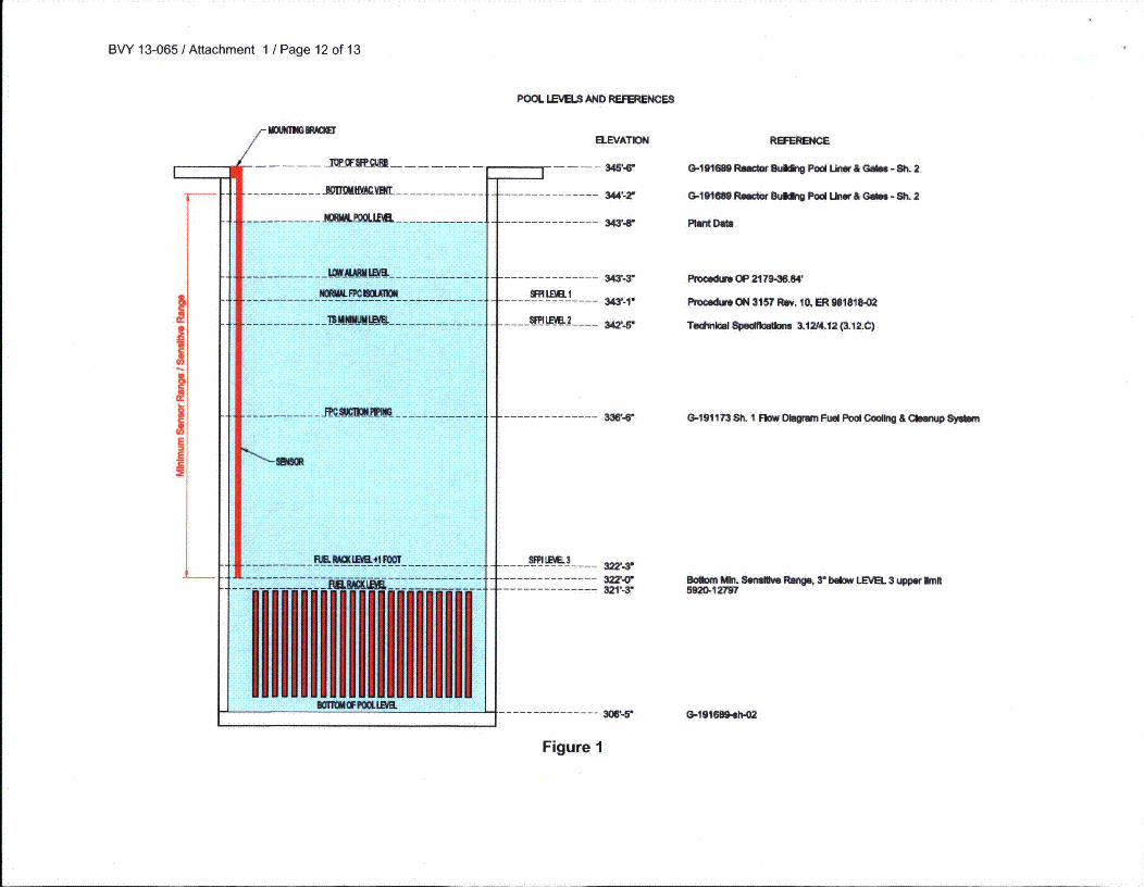
b) A clearly labeled sketch depicting the elevation view of the proposed typicalmounting arrangement for the portions of instrument channel consisting ofpermanent measurement channel equipment (e.g., fixed level sensors and/orstilling wells, and mounting brackets). Indicate on this sketch the datum valuesrepresenting Level 1, Level 2, and Level 3 as well as the top of the fuel. Indicate onthis sketch the portion of the level sensor measurement range that is sensitive tomeasurement of the fuel pool level, with respect to the Level 1, Level 2, and Level3 datum points.
c) The OIP states in Section 8, mounting,
"Other hardware stored in the SFP will be evaluated to ensure that it doesnot adversely interact with the SFP instrument probes during a seismicevent."
Given the potential for varied dose rates from other materials stored in the SFP,describe how level 2 will be adjusted to other than the elevation provided insection 2 above.
d) The OIP refers to drawings G-191173 Sh. 1, Revision 40 and 5920-12795, Revision0. Provide copies of these drawings and if they do not provide the necessaryinformation requested in this RAI, supplement it with additional drawings,sketches, and/or explanations.
Enterqy Response:
a) Additional analysis is in progress for NPSH at saturated conditions for establishment ofLevel 1. The updated information is currently scheduled to be included in the second six-month status report on February 28, 2014.
b) The requested information is provided in Figure 1. The figure indicates Levels 1, 2, and3 as well as the approximate location of the proposed mounting bracket incorporatingthe Seismic Category I attachment. The sensor is a perforated tubular coaxialwaveguide that provides continuous level measurement axially and is sensitive over itsentire length. These sketches apply to both the primary and backup channels.
The spent fuel pool (SFP) level lower instrument span or probe bottom extends down toat least three inches below the upper limit of the range of Level 3 to account for channelaccuracy or instrument loop uncertainty. Therefore, the SFP level probe bottom/spanextends down to at least elevation 322 feet (see Figure 1). The SFP level upperinstrument span, at a minimum, includes normal water level high alarm. Note that Level
BVY 13-065 / Attachment 1 / Page 2 of 13
3 is shown in accordance with Nuclear Energy Institute (NEI) 12-02 Revision 1 guidancerelative to the top of the rack; the top of the fuel is not shown.
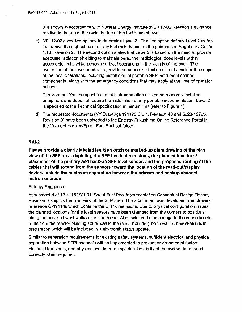
c) NEI 12-02 gives two options to determine Level 2. The first option defines Level 2 as tenfeet above the highest point of any fuel rack, based on the guidance in Regulatory Guide1.13, Revision 2. The second option states that Level 2 is based on the need to provideadequate radiation shielding to maintain personnel radiological dose levels withinacceptable limits while performing local operations in the vicinity of the pool. Theevaluation of the level needed to provide personnel protection should consider the scopeof the local operations, including installation of portable SFP instrument channelcomponents, along with the emergency conditions that may apply at the time of operatoractions.
The Vermont Yankee spent fuel pool instrumentation utilizes permanently installedequipment and does not require the installation of any portable instrumentation. Level 2is specified at the Technical Specification minimum limit (refer to Figure 1).
d) The requested documents (VY Drawings 191173 Sh. 1, Revision 40 and 5920-12795,Revision 0) have been uploaded to the Entergy Fukushima Online Reference Portal inthe Vermont Yankee/Spent Fuel Pool subfolder.
RAI-2
Please provide a clearly labeled legible sketch or marked-up plant drawing of the planview of the SFP area, depicting the SFP inside dimensions, the planned locations/placement of the primary and back-up SFP level sensor, and the proposed routing of thecables that will extend from the sensors toward the location of the read-out/displaydevice. Include the minimum separation between the primary and backup channelinstrumentation.
Entergy Response:
Attachment 4 of 12-4116.VY.001, Spent Fuel Pool Instrumentation Conceptual Design Report,Revision 0, depicts the plan view of the SFP area. The attachment was developed from drawingreference G-191149 which contains the SFP dimensions. Due to physical configuration issues,the planned locations for the level sensors have been changed from the corners to positionsalong the east and west walls at the south end. Also included is the change to the conduit/cableroute from the reactor building south wall to the reactor building north wall. A new sketch is inpreparation which will be included in a six-month status update.
Similar to separation requirements for existing safety systems, sufficient electrical and physicalseparation between SFPI channels will be implemented to prevent environmental factors,electrical transients, and physical events from impairing the ability of the system to respondcorrectly when required.
BVY 13-065 / Attachment 1 / Page 3 of 13
RAI-3
Please provide the following:
a) The design criteria that will be used to estimate the total loading on the mountingdevice(s), including static weight loads and dynamic loads. Describe themethodology that will be used to estimate the total loading, inclusive of designbasis maximum seismic loads and the hydrodynamic loads that could result frompool sloshing or other effects that could accompany such seismic forces.
b) A description of the manner in which the level sensor (and stilling well, ifappropriate) will be attached to the refueling roof and/or other support structuresfor each planned point of attachment of the probe assembly. Indicate in a drawingthe portions of the level sensor that will serve as points of attachment formechanical/mounting and electrical connections.
c) A description of the manner by which the mechanical connections will attach thelevel instrument to permanent SFP structures so as to support the level sensorassembly.
d) Address how other hardware stored in the SFP will not create adverse interactionwith the fixed instrument location(s).
Enterqy Response:
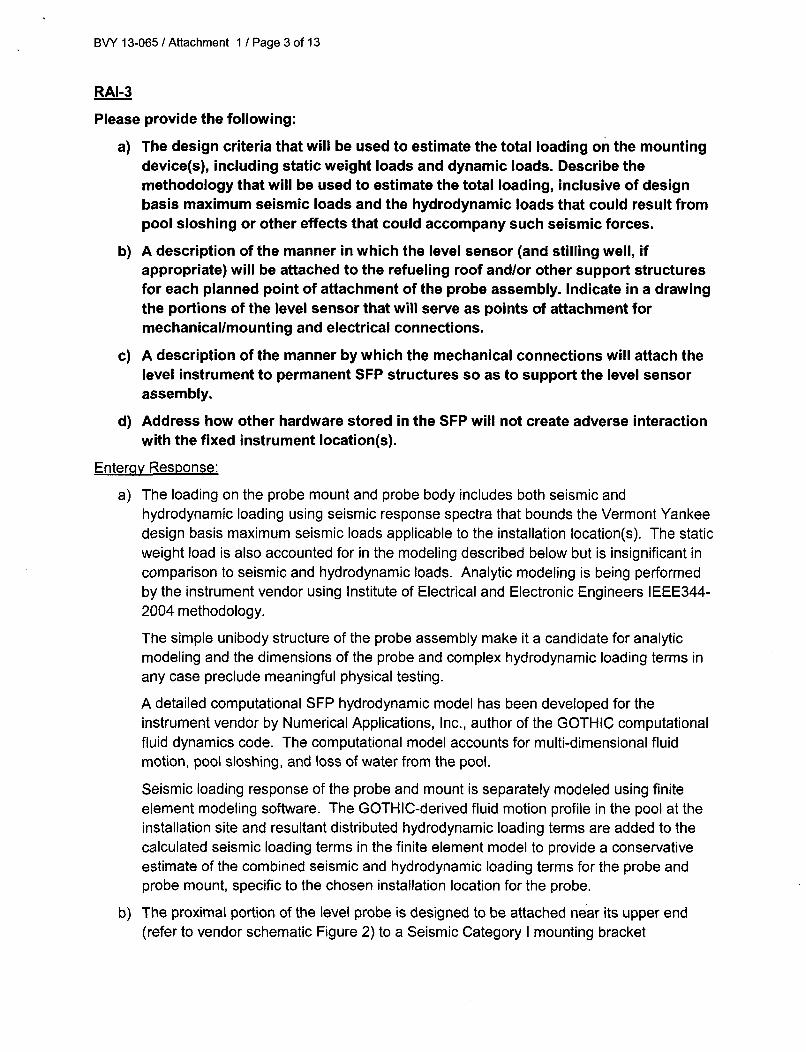
a) The loading on the probe mount and probe body includes both seismic andhydrodynamic loading using seismic response spectra that bounds the Vermont Yankeedesign basis maximum seismic loads applicable to the installation location(s). The staticweight load is also accounted for in the modeling described below but is insignificant in
comparison to seismic and hydrodynamic loads. Analytic modeling is being performedby the instrument vendor using Institute of Electrical and Electronic Engineers IEEE344-2004 methodology.
The simple unibody structure of the probe assembly make it a candidate for analyticmodeling and the dimensions of the probe and complex hydrodynamic loading terms inany case preclude meaningful physical testing.
A detailed computational SFP hydrodynamic model has been developed for theinstrument vendor by Numerical Applications, Inc., author of the GOTHIC computationalfluid dynamics code. The computational model accounts for multi-dimensional fluidmotion, pool sloshing, and loss of water from the pool.
Seismic loading response of the probe and mount is separately modeled using finiteelement modeling software. The GOTHIC-derived fluid motion profile in the pool at theinstallation site and resultant distributed hydrodynamic loading terms are added to thecalculated seismic loading terms in the finite element model to provide a conservativeestimate of the combined seismic and hydrodynamic loading terms for the probe andprobe mount, specific to the chosen installation location for the probe.
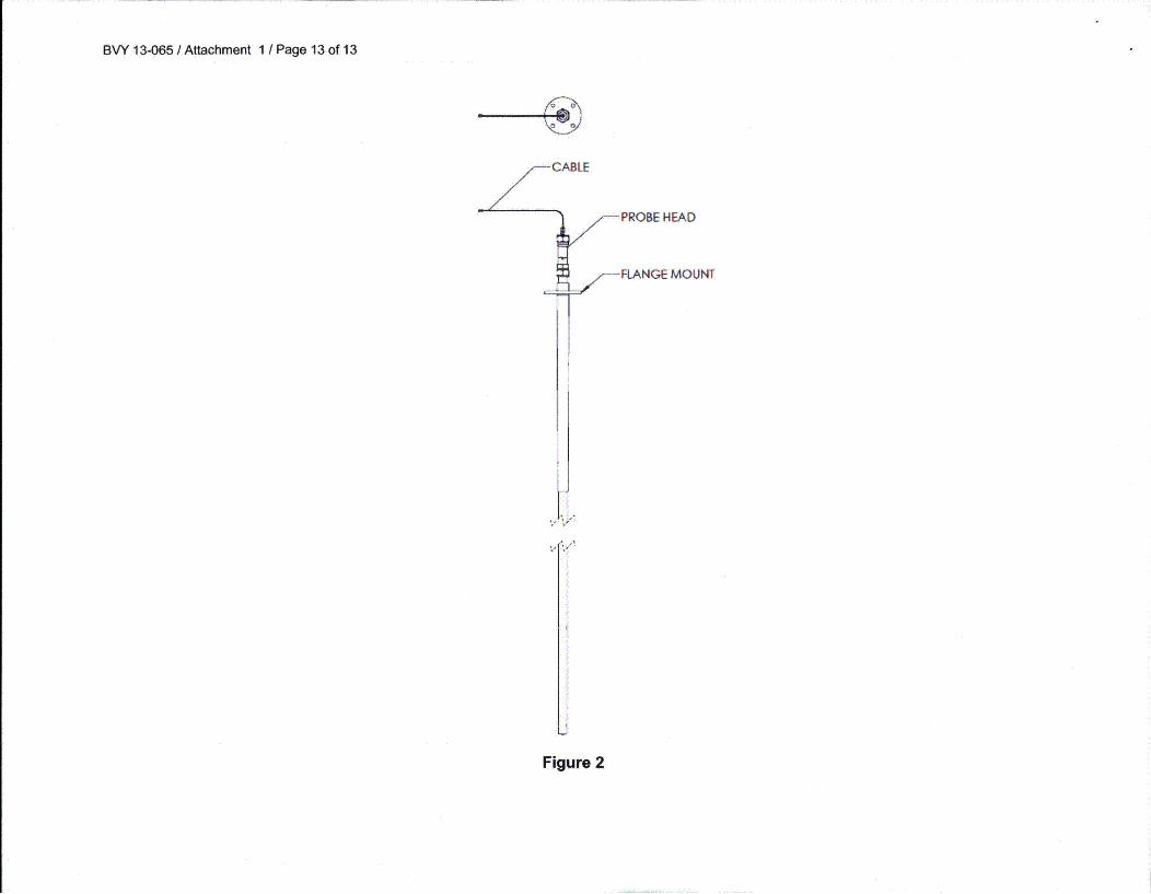
b) The proximal portion of the level probe is designed to be attached near its upper end(refer to vendor schematic Figure 2) to a Seismic Category I mounting bracket
BVY 13-065 / Attachment 1 / Page 4 of 13
configured to suit the requirements of a particular SFP. The bracket may be boltedand/or welded to the SFP deck and/or SFP liner/wall according to the requirements ofthe particular installation per Seismic Category I requirements.
c) See RAI-3.b response above.
d) An evaluation of non-special nuclear material inventory located in the SFP will beperformed during the SFPI modification process. Non-special nuclear material access tothe SFP is governed by DP 0545, Fuel Pool Storage Requirements. This procedure willbe used to prevent any instrument interference from non-special nuclear materials.
RAI-4
Please provide the following:
a) A description of the specific method or combination of methods that will beapplied to demonstrate the reliability of the permanently installed equipmentunder Beyond-Design-Basis (BDB) ambient temperature, humidity, shock,vibration, and radiation conditions.
b) A description of the testing andlor analyses that will be conducted to provideassurance that the equipment will perform reliably under the worst-case credibledesign basis loading at the location where the equipment will be mounted. Includea discussion of this seismic reliability demonstration as it applies to (1) the levelsensor mounted in the SFP area, and (2) any control boxes, electronics, or read-out and re-transmitting devices that will be employed to convey the levelinformation from the level sensor to the plant operators or emergency responders.
c) A description of the specific method or combination of methods that will be usedto confirm the reliability of the permanently installed equipment such thatfollowing a seismic event, the instrument will maintain its required accuracy.
Entercqy Response:
a) As stated in NEI 12-02, "Components in the area of the SFP will be designed for thetemperature, humidity, and radiation levels expected during normal, event, and post-event conditions...." Components in other areas are planned to be designed for theircorresponding maximum conditions. The discussion below describes the testing andqualification intended to demonstrate equipment reliability as needed for the expectedconditions associated with the SFP level channel active components (signal processorand probe assembly including vendor-supplied hard-line coaxial cable pigtail). Class 1 Enuclear-qualified interconnecting coaxial cable is planned to be utilized between thevendor-supplied probe coaxial cable pigtail and the signal processor / display located inthe control room.
BVY 13-065 / Attachment 1 / Page 5 of 13
Temperature:
Signal processor: Designed for mild environment installation. Physical testing inan environmental chamber to demonstrate normal operation at the operatingtemperatures specified for the instrument.
Probe assembly: Qualification by materials properties and use history ofsubstantially similar probe designs in steam generator applications at significantlyhigher temperatures and pressures and saturated steam environments.
Humidity:
Signal processor: Designed for mild environment installation. Physical testing inan environmental chamber to demonstrate normal operation at the operatinghumidity specified for the instrument.
Probe assembly: Qualification by materials properties and use history as notedabove.
Shock:
Signal processor: Physical testing to commercial and/or military standards usingshake-table and drop testing.
Probe assembly: Finite element analysis in conjunction with seismic modelingdescribed above.
Vibration:
Signal processor: Physical testing to applicable commercial and/or military
standards using shake-table and drop testing.
Probe assembly: The probe assembly and bracket together form a simple staticunibody structure with intrinsic vibration resistance that is additionally subject tosubstantial damping due to the surrounding water medium. This is planned to bemodeled using finite element modeling in conjunction with seismic modelingdescribed above.
Radiation:
Signal processor: The signal processor is installed in a mild environment withradiation levels similar to background radiation, with the acknowledgement thatthe radiation limit for the signal processor is similar to other commercial-gradecomplementary-metal-oxide-semiconductor (CMOS)-based electronics.Radiation testing is not planned. It should be noted that the instrument performsself-diagnostics before measurements are obtained and the electronics are easilyaccessible for periodic replacement.
Probe assembly: Materials properties qualification is used.
b) Signal processor (electronics): Triaxial shake-table testing is planned to be performedby the vendor to envelope seismic category 1 safe shutdown earthquake (SSE)
BVY 13-065 / Attachment 1 / Page 6 of 13
conditions or VY design basis maximum seismic loads (relative to the location where theequipment is mounted) using IEEE344-2004 methodology.
Probe assembly (level sensor): Seismic and hydrodynamic finite element analysis isperformed by the vendor using relevant IEEE344-2004 methodology (using envelopingseismic category 1 SSE conditions or VY design basis maximum seismic loads relativeto the location where the equipment is mounted), as described in the RAI-3.a responseabove.
c) With respect to the probe assembly, combined seismic and hydrodynamic analysis willbe used to demonstrate that the probe waveguide's geometric dimensions do notchange significantly as a result of the seismic conditions. In the absence of alteration tothe geometric configuration of the probe waveguide there is no mechanism for seismicexcitation of the probe assembly to alter system accuracy.
The accuracy of system electronics will be demonstrated following seismic excitation aspart of the seismic testing protocol.
RAI-5
Please provide the following:
a) A description of how the two channels of the proposed level measurement systemmeet this requirement so that the potential for a common cause event to adverselyaffect both channels is minimized to the extent practicable.
b) Further information on how each level measurement system, consisting of levelsensor electronics, cabling, and readout devices will be designed and installed toaddress independence through the application and selection of independentpower sources, independence of signals sent to the location(s) of the readoutdevices, and the independence of the displays.
Enter-qy Response:
a) The primary instrument (Channel A) will be along the east wall and the backupinstrument (Channel B) will be along the west wall of the SFP, both at the south end.Locating the new instruments along opposite walls of the SFP takes advantage of thedistance between the probes (approximately 39 feet) for missile and debris protection.Channel A and B displays will be located in the main control room on the existing panelscontaining the Containment Atmospheric Dilution (CAD) System components.
The conceptual design provides two independent level instruments in the SFP withcabling routed to two display/processors mounted in the Main Control Room (MCR).Power for each channel is provided from independent 120VAC, 60 Hz power sources.Backup power is provided by a battery capable of providing continuous display operationfor at least three days. The battery will be provided with the display/processor. Thedesign prevents failure of a single channel from causing the alternate channel to fail.Channel separation and independence are maintained consistent with existing designbasis requirements.
BVY 13-065 / Attachment 1 / Page 7 of 13
b) The design provides two identical non-safety related wide-range level instruments whichfeed two independent trains of non-safety cable and indicators to provide a highlyreliable remote display of SFP water level in the main control room. Physical separationof the two channels will be accomplished by separately routing cable and conduit asmuch as practical. The use of raceways (i.e., conduit or covered trays whereappropriate for existing hazards) will provide additional protection from damage due todebris during a BDB event.
Each Control Room display/processor will have a battery installed in the displayenclosure which is capable of providing power for at least three days.
RAI-6
Please provide the design criteria that will be applied to size the battery in a manner thatensures, with margin, that the channel will be available to run reliably and continuouslyfollowing the onset of the BDB event for the minimum duration needed, consistent withthe plant mitigation strategies for beyond-design-basis external events (Order EA-12-049).
Enterqy Response:
The sample rate estimates have been developed by the vendor using conservative instrumentpower requirements and measured battery capacity with draw-downs during and followingexposure of the batteries to their maximum operating temperature for up to seven days. Theinstrument configuration is planned to be established for an automated sample rate when underbattery power consistent with seven days continuous operation. Permanent installed batterycapacity for seven days continuous operation is planned consistent with NEI 12-02 durationwithout reliance on or crediting of potentially more rapid FLEX Program power restoration.Batteries are readily replaceable via spare stock without the need for recalibration to maintainaccuracy of the instrument. These measures ensure adequate power capacity and margin.
RAI-7
Please provide the following:
a) An estimate of the expected instrument channel accuracy performance (in percentof span) under both (a) normal SFP level conditions (approximately Level I orhigher) and (b) at the BDB conditions (i.e., radiation, temperature, humidity, post-seismic and post-shock conditions) that would be present if the SFP level were atthe Level 2 and Level 3 datum points.
b) A description of the methodology that will be used for determining the maximumallowed deviation from the instrument channel design accuracy that will beemployed under normal operating conditions as an acceptance criterion for acalibration procedure to flag to operators and to technicians that the channelrequires adjustment to within the normal condition design accuracy.
BVY 13-065 / Attachment 1 / Page 8 of 13
Enterqy Response:
a) The instrument channel level accuracy will be specified as less than ± 3.0 inches for allexpected conditions. The expected instrument channel accuracy performance would beapproximately ±1% of span (based on the sensitive range of the detector).
b) In general relative to normal operating conditions, any applicable calibration proceduretolerances (or acceptance criterion) are planned to be established based onmanufacturer's stated/recommended reference accuracy (or design accuracy). Themethodology used is planned to be captured in plant procedures and/or programs.
RAI-8
Please provide the following:
a) A description of the capability and provisions the proposed level sensingequipment will have to enable periodic testing and calibration, including how thiscapability enables the equipment to be tested in-situ.
b) A description how such testing and calibration will enable the conduct of regularchannel checks of each independent channel against the other, and against anyother permanently installed SFP level instrumentation.
c) A description of the calibration and functional checks that will be performed, thefrequency at which they will be conducted with a discussion on the measurestaken to detect when the instrumentation is operable but degraded, and how thesesurveillances will be incorporated into the plant surveillance program.
d) A description of the preventative maintenance tasks required to be performedduring normal operation, and the planned maximum surveillance interval that isnecessary to ensure that the channels are fully conditioned to accurately andreliably perform their functions when needed.
Enterqy Response:
a) The level instrument automatically monitors the integrity of its level measurement systemusing in-situ capability. Deviation of measured test parameters from manufactured oras-installed configuration beyond a configurable threshold prompts operator intervention.
Periodic calibration checks of the signal processor electronics to extrinsic NationalInstitute of Standards and Technology (NIST)-traceable standards can be achievedthrough the use of standard measurement and test equipment.
The probe itself is a perforated tubular coaxial waveguide with defined geometry and isnot calibrated. It is planned to be periodically inspected electromagnetically using time-domain reflectometry (TDR) at the probe hardline cable connector to demonstrate thatthe probe assembly meets manufactured specification and visually to demonstrate thatthere has been no mechanical deformation or fouling.
BVY 13-065 / Attachment 1 / Page 9 of 13
b) Each instrument electronically logs a record of measurement values over time in non-volatile memory that is compared to demonstrate constancy, including any changes inpool level, such as that associated with the normal evaporative loss/refilling cycle. The
channel level measurements can be directly compared to each other (i.e., regular cross-channel comparisons). The two displays are installed in close proximity to each other,thus simplifying cross channel checks. Direct measurements of SFP level may be usedfor diagnostic purposes if cross-channel comparisons are anomalous.
c) Performance tests (functional checks) are automated and/or semi-automated (requiringlimited operator interaction) and are performed through the instrument menu softwareand initiated by the operator. There are a number of other internal system tests that areperformed by system software on an essentially continuous basis without user
intervention but which can also be performed on an on-demand basis with diagnosticoutput to the display for the operator to review. Other tests such as menu button tests,level alarm, and alarm relay tests are only initiated manually by the operator.Performance checks are described in detail in the Vendor Operator's Manual, and theapplicable information is planned to be contained in plant operating procedures.
Performance tests are planned to be performed periodically as recommended by theequipment vendor, for instance quarterly but no less often than the calibration interval oftwo years.
Channel functional tests per operations procedures with limits established inconsideration of vendor equipment specifications are planned to be performed atappropriate frequencies established equivalent to or more frequently than existing spentfuel pool instrumentation.
Manual calibration tests are as described above in RAI-8.a and b.
Manual calibration and operator performance checks are planned to be performed in aperiodic scheduled fashion with additional maintenance on an as-needed basis whenflagged by the system's automated diagnostic testing features.
Channel calibration tests per maintenance procedures with limits established inconsideration of vendor equipment specifications are planned to be performed atfrequencies established in consideration of vendor recommendations.
d) Periodic (e.g., quarterly or monthly) review of the system level history and log files androutine attention to any warning message on the system display is recommended by thevendor. Formal calibration checks are recommended by the vendor on a two-yearinterval to demonstrate calibration to external NIST-traceable standards. Formalcalibration check surveillance interval and timing would be established consistent withapplicable guidance [i.e., NEI 12-02 Section 4.3; on a refueling outage interval basis andwithin 60 days of a planned refueling outage]. Items such as system batteries areplanned to be assessed under the Preventive Maintenance (PM) program forestablishment of replacement frequency. Surveillance/PM timing/performance areplanned to be controlled via tasks in the PM program.
BVY 13-065 / Attachment 1 1 Page 10 of 13
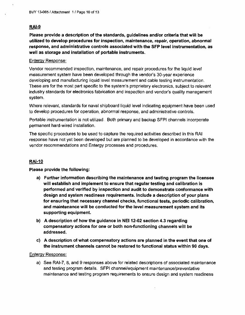
RAI-9
Please provide a description of the standards, guidelines and/or criteria that will beutilized to develop procedures for inspection, maintenance, repair, operation, abnormalresponse, and administrative controls associated with the SFP level instrumentation, aswell as storage and installation of portable instruments.
Entergy Response:
Vendor recommended inspection, maintenance, and repair procedures for the liquid levelmeasurement system have been developed through the vendor's 30-year experiencedeveloping and manufacturing liquid level measurement and cable testing instrumentation.These are for the most part specific to the system's proprietary electronics, subject to relevantindustry standards for electronics fabrication and inspection and vendor's quality managementsystem.
Where relevant, standards for naval shipboard liquid level indicating equipment have been usedto develop procedures for operation, abnormal response, and administrative controls.
Portable instrumentation is not utilized. Both primary and backup SFPI channels incorporatepermanent hard-wired installation.
The specific procedures to be used to capture the required activities described in this RAIresponse have not yet been developed but are planned to be developed in accordance with thevendor recommendations and Entergy processes and procedures.
RAI-1 0
Please provide the following:
a) Further information describing the maintenance and testing program the licenseewill establish and implement to ensure that regular testing and calibration isperformed and verified by inspection and audit to demonstrate conformance withdesign and system readiness requirements. Include a description of your plansfor ensuring that necessary channel checks, functional tests, periodic calibration,and maintenance will be conducted for the level measurement system and itssupporting equipment.
b) A description of how the guidance in NEI 12-02 section 4.3 regardingcompensatory actions for one or both non-functioning channels will beaddressed.
c) A description of what compensatory actions are planned in the event that one ofthe instrument channels cannot be restored to functional status within 90 days.
Enterqy Response:
a) See RAI-7, 8, and 9 responses above for related descriptions of associated maintenanceand testing program details. SFPI channel/equipment maintenance/preventativemaintenance and testing program requirements to ensure design and system readiness
BVY 13-065 / Attachment 1 / Page 11 of 13
are planned to be established in accordance with Entergy's processes and proceduresand in consideration of vendor recommendations to ensure that appropriate regulartesting, channel checks, functional tests, periodic calibration, and maintenance isperformed. Subject maintenance and testing program requirements are planned to bedeveloped during the SFPI modification design process.
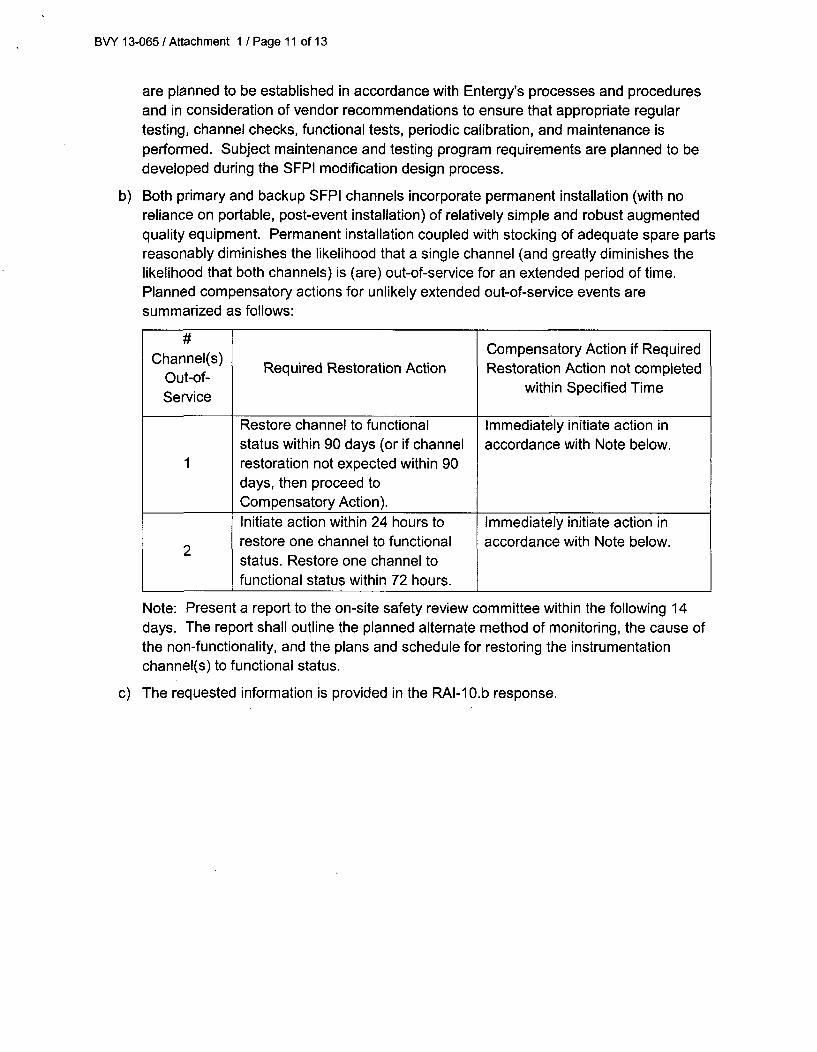
b) Both primary and backup SFPI channels incorporate permanent installation (with noreliance on portable, post-event installation) of relatively simple and robust augmentedquality equipment. Permanent installation coupled with stocking of adequate spare partsreasonably diminishes the likelihood that a single channel (and greatly diminishes thelikelihood that both channels) is (are) out-of-service for an extended period of time.Planned compensatory actions for unlikely extended out-of-service events aresummarized as follows:
#l Compensatory Action if RequiredChannel(s) Required Restoration Action Restoration Action not completed
Out-of- within Specified TimeService
Restore channel to functional Immediately initiate action instatus within 90 days (or if channel accordance with Note below.
1 restoration not expected within 90days, then proceed toCompensatory Action).Initiate action within 24 hours to Immediately initiate action inrestore one channel to functional accordance with Note below.status. Restore one channel tofunctional status within 72 hours.
Note: Present a report to the on-site safety review committee within the following 14days. The report shall outline the planned alternate method of monitoring, the cause ofthe non-functionality, and the plans and schedule for restoring the instrumentationchannel(s) to functional status.
c) The requested information is provided in the RAI-10.b response.
BVY 13-065 / Attachment 1 / Page 12 of 13
POOL. LEVELS AND REFERENCES
- MLFMWOELEVATION
---- -34-
-347~-r
REFERENCE
G-10161M Rect # Ik¶ Pod LhW & GMMs - Eli 2
G-1916Nft~carbimbig Pad Lhu& Gelts-SKi.2
PIW4 Dtin
-- 3424.r
Proosfte OP 2179-.W664
Pmdu ON 3157 Rev. 10, ER 9W1l16i0
TodmitmiSpedfluilon. 3.12t12 (3.12.0)
0-191173 SL. 1 ROW OWsgruv FuLM PONl Coam & CbeNup SYSWIs
sowm mbi. swtloo Range r eo LEVEL 3 iupe buNtSOM2M~7
G-1916894h-02
--- - -- - -321'-r
---- -- -- - W -
Figure 1
BVY 13-065 / Attachment 1 / Page 13 of 13
///,CABLE
PROBEHEAD
FLANGE MOUNT
Figure 2