enhanced seismic design of shallow foundation
DESCRIPTION
shallow foundationTRANSCRIPT
4th Athenian Lecture on Geotechnical Engineering, 2006
Enhanced seismic design of shallow foundations: example of the Rion Antirion Bridge A. PECKER1
ABSTRACT Once earthquake risk and site effects have been evaluated the foundation designer needs to proceed with the proportioning of the foundation. To date there is little in the way of code recommendations to cover this, especially along the emerging trends of performance based design. Eurocode 8 is an exception and contains an extensive section on the design of foundations to resist earthquake loading. This has been developed using the results of a number of special investigations, both laboratory and theoretical. This presentation will cover the background to the provisions in the Eurocode related to shallow foundations and will take advantage of the Rion Antirion bridge, recently completed, to illustrate the foundation seismic design process; furthermore this example will serve to show how seismic foundation reliability can be enhanced beyond the code requirements with simple, reliable, concepts borrowed from structural engineering. INTRODUCTION
Design of foundations still remains a challenging task for the earthquake geotechnical engineer. Leaving aside the seismic retrofit of existing foundations, which is an even more difficult issue, the design of new foundations raises issues which are far from being totally resolved. One of the main reasons stems from the complexity of the problem which requires skills in soil mechanics, foundation engineering, and soil-structure interaction along with, at least, some knowledge of structural dynamics.
A parallel between static design and seismic design reveals some similarity but also very marked differences. In the early days, static design of foundations put much emphasis on the so-called bearing capacity problem (failure behavior); with the introduction of an appropriate safety factor, close to 3, the short term settlements were deemed to be acceptable for the structure. It is only with the increase in the understanding of soil behavior and the development of reliable constitutive models that sound predictions of settlements could be achieved. Not surprisingly, earthquake geotechnical engineers have focused their attention on the cyclic non linear behavior of soils and on the evaluation of the cyclic deformations of foundations. This was clearly dictated by the need for an accurate evaluation of the soil-structure interaction forces which govern the structural response. It is only during the last decade that seismic bearing capacity problems and evaluation of permanent displacements have been tackled. These studies have clearly been motivated by the foundation failures observed in the Mexico City (1985) and Kobe (1995) earthquakes.
These two aspects of foundation design have reached a state of development where they can be incorporated in seismic building codes; Eurocode 8 - Part 5 is certainly a pioneering code in that respect. Nevertheless, a new trend is emerging in earthquake engineering, known as "Performance Based Design" (PBD), which definitely needs to be accounted for in earthquake foundation engineering.
In this paper, the fundamental aspects underlying the earthquake resistant design of foundations will be reviewed and their implementation in seismic building codes will be discussed and illustrated with the example of the Rion Antirion bridge recently completed in Greece; furthermore, this example will serve as a
1 Chairman and Managing Director, Géodynamique & Structure, Bagneux, France. Associate Research Director, Solid Mechanics Laboratory, CNRS UMR 7649, Ecole Polytechnique, Palaiseau, France.
basis to illustrate how foundation reliability can be enhanced by implementing simple concepts borrowed from structural engineering.
ASEISMIC FOUNDATION DESIGN PROCESS
The aseismic design process for foundations is a "very broad activity requiring the synthesis of insight, creativity, technical knowledge and experience" (Pender, 1995). Information is required and decisions have to be made at various stages including (Pecker and Pender, 2000): (i) the geological environment and geotechnical characterization of the soil profile; (ii) the investigation of possible solutions (iii) the definition of the loads that will be applied to the foundation soil by the facility to be constructed; (iv) information about the required performance of the structure; (v) the evaluation of load capacity, assessment of safety factors and estimates of deformations; (vi) consideration of construction methods and constraints that need to be satisfied (finance and time); (vii) exercise of judgment to assess potential risks.
Obviously the process described above is not a linear progression. All steps are closely interrelated and several iterations may be required, at least from step (ii) to step (vii), before arriving at a feasible, reliable and economic design. In the following we will not discuss the steps towards the definition of the soil characterization and will assume that all the required information is available. This, in no way, means that this item is of secondary importance; these data are probably the most difficult to obtain and to assess and considerable experience is required as well as the exercise of judgment.
DESCRIPTION OF THE RION ANTIRION BRIGE
The Rion-Antirion bridge project is a BOT contract granted by the Greek Government to a consortium led by the French company Vinci Construction (formerly Dumez-GTM) in association with seven Greek companies. It is located in Greece, near Patras, will constitute a fixed link between the Peloponese and the Continent across the western end of the Gulf of Corinth and is intended to replace an existing ferry system (Figure 1). The solution adopted for this bridge is a multiple spans cable stayed bridge with four main piers; the three central spans are 560m long each and are extended by two adjacent spans (one on each side) 286m long.
Figure 1: Location of the bridge
2
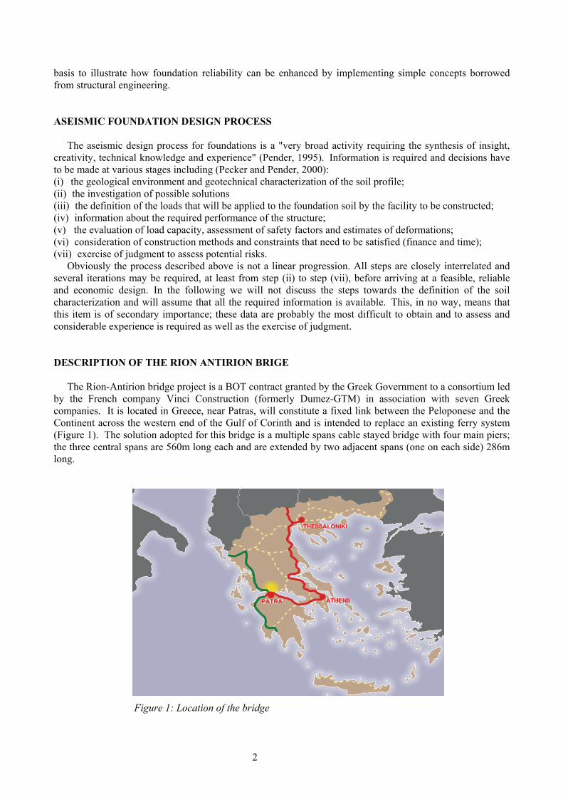
The total length of the bridge, with the approach viaducts, is approximately 2.9 kilometers (Figure 2). The call for tender was launched in 1992, the contract, awarded to the consortium in 1996, took effect in December 1997. Construction started in 1998 and has been completed in summer 2004 and the bridge was opened to traffic on the 11th of August, five months ahead of schedule.
Figure 2: Bridge elevation
The site has been subjected to extensive offshore soil investigations performed either from floating barges
or from a ship, controlled with a dynamic positioning system; these investigations included cored boreholes, static Cone Penetration Tests with pore pressure measurements (CPTU), Standard Penetration tests (SPT), vane tests and dilatometer tests, seismic cone tests and sampling of intact soil samples for laboratory testing. All the borings reached depths ranging from 60m to 100m below the sea bed. Under each of the main bridge pier three continuous boreholes, three CPTU, two seismic cones, one SPT/dilatometer boring have been drilled. Approximately 300 samples have been retrieved and subjected to advanced laboratory testing. Based on the results of these investigations representative soil profiles have been defined at the locations of the main bridge piers and ranges of soil mechanical characteristics have been derived (Pecker, 2003).
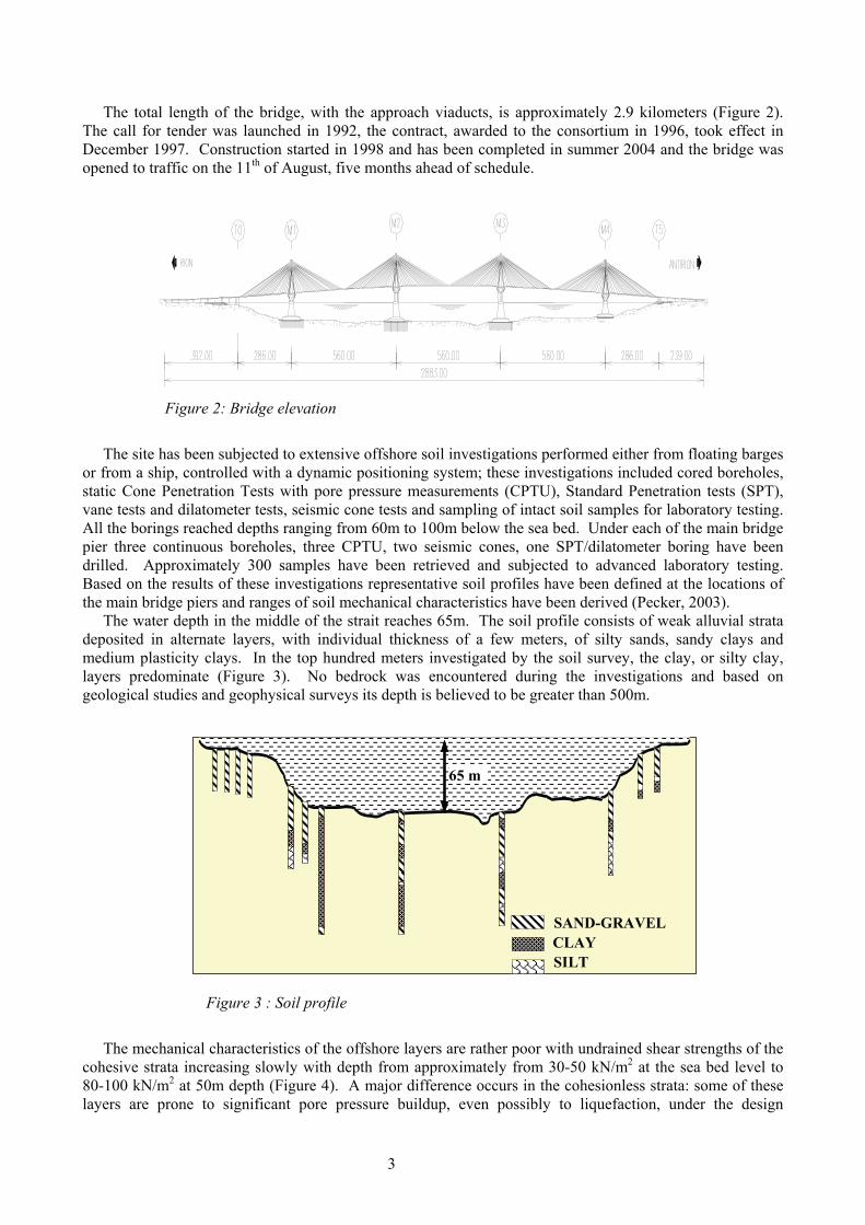
The water depth in the middle of the strait reaches 65m. The soil profile consists of weak alluvial strata deposited in alternate layers, with individual thickness of a few meters, of silty sands, sandy clays and medium plasticity clays. In the top hundred meters investigated by the soil survey, the clay, or silty clay, layers predominate (Figure 3). No bedrock was encountered during the investigations and based on geological studies and geophysical surveys its depth is believed to be greater than 500m.
65 m65 m
CLAY SILT
SAND-GRAVEL
Figure 3 : Soil profile
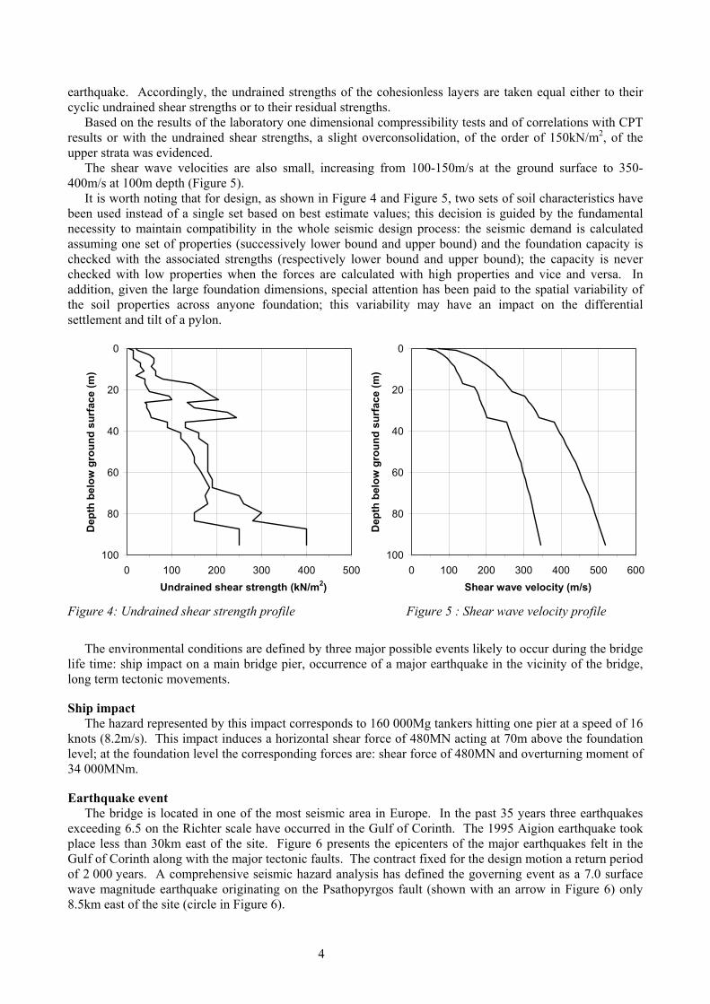
The mechanical characteristics of the offshore layers are rather poor with undrained shear strengths of the
cohesive strata increasing slowly with depth from approximately from 30-50 kN/m2 at the sea bed level to 80-100 kN/m2 at 50m depth (Figure 4). A major difference occurs in the cohesionless strata: some of these layers are prone to significant pore pressure buildup, even possibly to liquefaction, under the design
3
earthquake. Accordingly, the undrained strengths of the cohesionless layers are taken equal either to their cyclic undrained shear strengths or to their residual strengths.
Based on the results of the laboratory one dimensional compressibility tests and of correlations with CPT results or with the undrained shear strengths, a slight overconsolidation, of the order of 150kN/m2, of the upper strata was evidenced.
The shear wave velocities are also small, increasing from 100-150m/s at the ground surface to 350-400m/s at 100m depth (Figure 5).
It is worth noting that for design, as shown in Figure 4 and Figure 5, two sets of soil characteristics have been used instead of a single set based on best estimate values; this decision is guided by the fundamental necessity to maintain compatibility in the whole seismic design process: the seismic demand is calculated assuming one set of properties (successively lower bound and upper bound) and the foundation capacity is checked with the associated strengths (respectively lower bound and upper bound); the capacity is never checked with low properties when the forces are calculated with high properties and vice and versa. In addition, given the large foundation dimensions, special attention has been paid to the spatial variability of the soil properties across anyone foundation; this variability may have an impact on the differential settlement and tilt of a pylon.
0
20
40
60
80
1000 100 200 300 400 500
Undrained shear strength (kN/m2)
Dep
th b
elow
gro
und
surf
ace
(m)
0
20
40
60
80
1000 100 200 300 400 500 600
Shear wave velocity (m/s)
Dep
th b
elow
gro
und
surf
ace
(m)
Figure 4: Undrained shear strength profile Figure 5 : Shear wave velocity profile
The environmental conditions are defined by three major possible events likely to occur during the bridge
life time: ship impact on a main bridge pier, occurrence of a major earthquake in the vicinity of the bridge, long term tectonic movements. Ship impact
The hazard represented by this impact corresponds to 160 000Mg tankers hitting one pier at a speed of 16 knots (8.2m/s). This impact induces a horizontal shear force of 480MN acting at 70m above the foundation level; at the foundation level the corresponding forces are: shear force of 480MN and overturning moment of 34 000MNm. Earthquake event
The bridge is located in one of the most seismic area in Europe. In the past 35 years three earthquakes exceeding 6.5 on the Richter scale have occurred in the Gulf of Corinth. The 1995 Aigion earthquake took place less than 30km east of the site. Figure 6 presents the epicenters of the major earthquakes felt in the Gulf of Corinth along with the major tectonic faults. The contract fixed for the design motion a return period of 2 000 years. A comprehensive seismic hazard analysis has defined the governing event as a 7.0 surface wave magnitude earthquake originating on the Psathopyrgos fault (shown with an arrow in Figure 6) only 8.5km east of the site (circle in Figure 6).
4
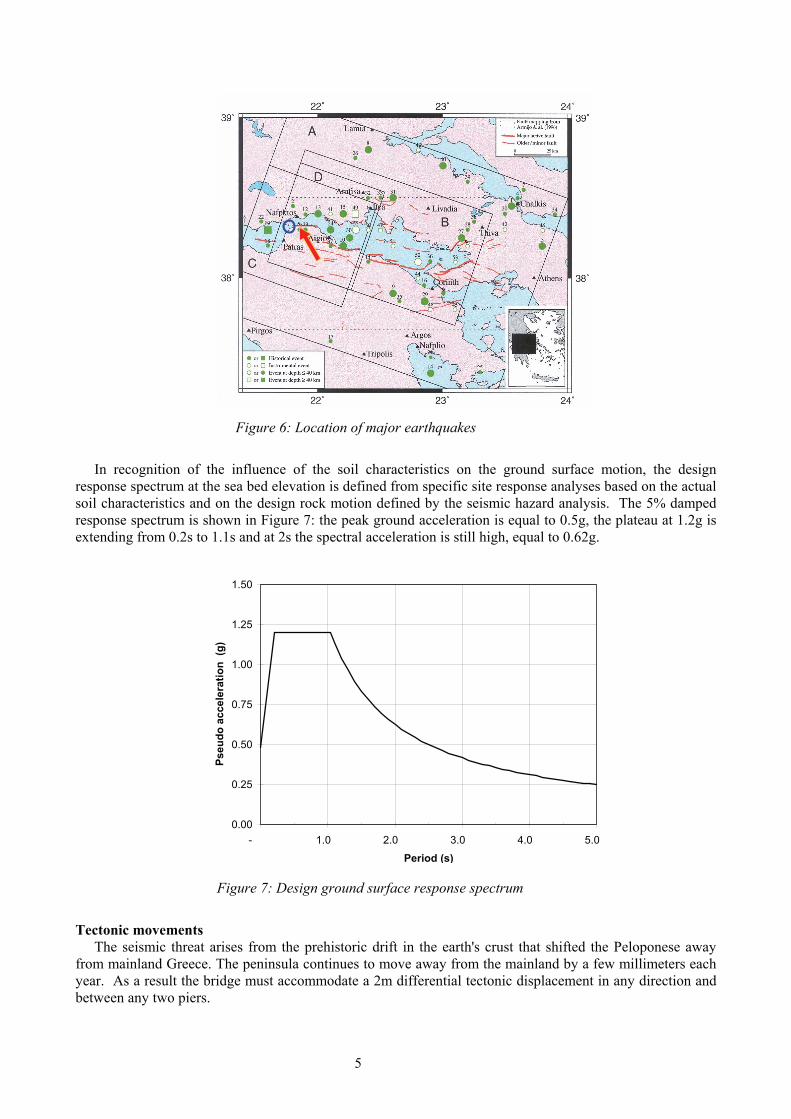
Figure 6: Location of major earthquakes
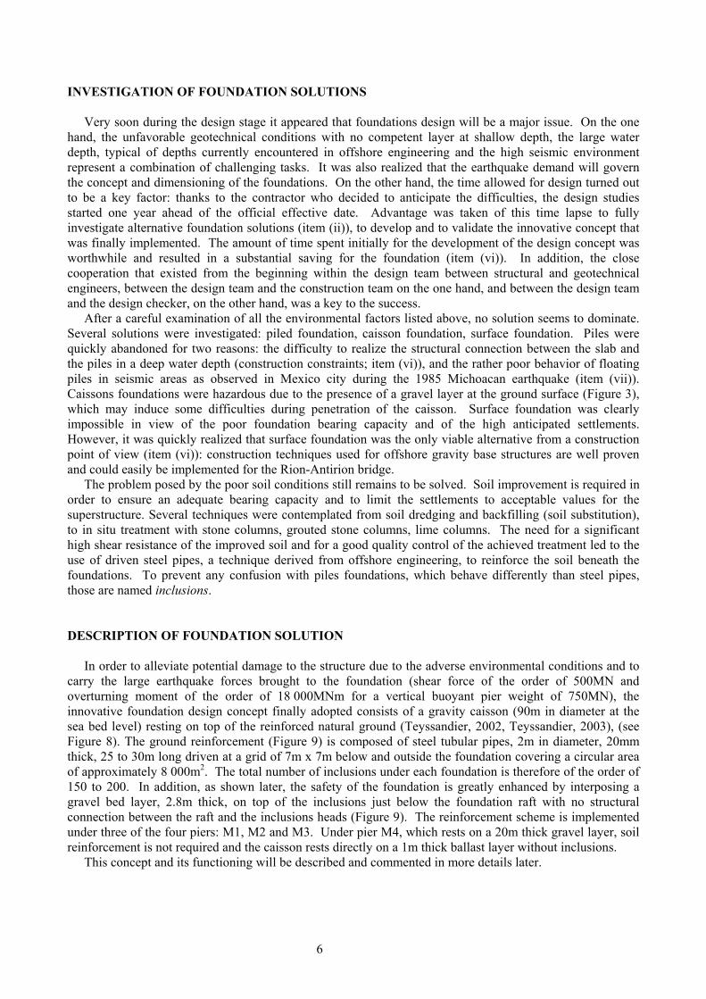
In recognition of the influence of the soil characteristics on the ground surface motion, the design
response spectrum at the sea bed elevation is defined from specific site response analyses based on the actual soil characteristics and on the design rock motion defined by the seismic hazard analysis. The 5% damped response spectrum is shown in Figure 7: the peak ground acceleration is equal to 0.5g, the plateau at 1.2g is extending from 0.2s to 1.1s and at 2s the spectral acceleration is still high, equal to 0.62g.
0.00
0.25
0.50
0.75
1.00
1.25
1.50
- 1.0 2.0 3.0 4.0 5.0
Period (s)
Pseu
do a
ccel
erat
ion
(g)
Figure 7: Design ground surface response spectrum
Tectonic movements
The seismic threat arises from the prehistoric drift in the earth's crust that shifted the Peloponese away from mainland Greece. The peninsula continues to move away from the mainland by a few millimeters each year. As a result the bridge must accommodate a 2m differential tectonic displacement in any direction and between any two piers.
5
INVESTIGATION OF FOUNDATION SOLUTIONS
Very soon during the design stage it appeared that foundations design will be a major issue. On the one hand, the unfavorable geotechnical conditions with no competent layer at shallow depth, the large water depth, typical of depths currently encountered in offshore engineering and the high seismic environment represent a combination of challenging tasks. It was also realized that the earthquake demand will govern the concept and dimensioning of the foundations. On the other hand, the time allowed for design turned out to be a key factor: thanks to the contractor who decided to anticipate the difficulties, the design studies started one year ahead of the official effective date. Advantage was taken of this time lapse to fully investigate alternative foundation solutions (item (ii)), to develop and to validate the innovative concept that was finally implemented. The amount of time spent initially for the development of the design concept was worthwhile and resulted in a substantial saving for the foundation (item (vi)). In addition, the close cooperation that existed from the beginning within the design team between structural and geotechnical engineers, between the design team and the construction team on the one hand, and between the design team and the design checker, on the other hand, was a key to the success.
After a careful examination of all the environmental factors listed above, no solution seems to dominate. Several solutions were investigated: piled foundation, caisson foundation, surface foundation. Piles were quickly abandoned for two reasons: the difficulty to realize the structural connection between the slab and the piles in a deep water depth (construction constraints; item (vi)), and the rather poor behavior of floating piles in seismic areas as observed in Mexico city during the 1985 Michoacan earthquake (item (vii)). Caissons foundations were hazardous due to the presence of a gravel layer at the ground surface (Figure 3), which may induce some difficulties during penetration of the caisson. Surface foundation was clearly impossible in view of the poor foundation bearing capacity and of the high anticipated settlements. However, it was quickly realized that surface foundation was the only viable alternative from a construction point of view (item (vi)): construction techniques used for offshore gravity base structures are well proven and could easily be implemented for the Rion-Antirion bridge.
The problem posed by the poor soil conditions still remains to be solved. Soil improvement is required in order to ensure an adequate bearing capacity and to limit the settlements to acceptable values for the superstructure. Several techniques were contemplated from soil dredging and backfilling (soil substitution), to in situ treatment with stone columns, grouted stone columns, lime columns. The need for a significant high shear resistance of the improved soil and for a good quality control of the achieved treatment led to the use of driven steel pipes, a technique derived from offshore engineering, to reinforce the soil beneath the foundations. To prevent any confusion with piles foundations, which behave differently than steel pipes, those are named inclusions.
DESCRIPTION OF FOUNDATION SOLUTION
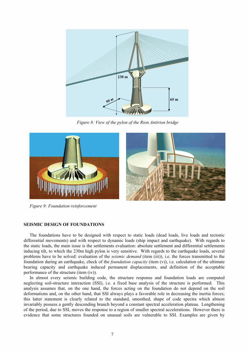
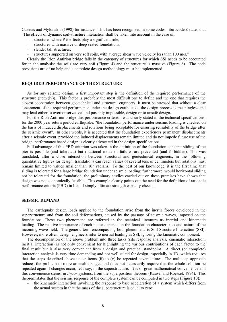
In order to alleviate potential damage to the structure due to the adverse environmental conditions and to carry the large earthquake forces brought to the foundation (shear force of the order of 500MN and overturning moment of the order of 18 000MNm for a vertical buoyant pier weight of 750MN), the innovative foundation design concept finally adopted consists of a gravity caisson (90m in diameter at the sea bed level) resting on top of the reinforced natural ground (Teyssandier, 2002, Teyssandier, 2003), (see Figure 8). The ground reinforcement (Figure 9) is composed of steel tubular pipes, 2m in diameter, 20mm thick, 25 to 30m long driven at a grid of 7m x 7m below and outside the foundation covering a circular area of approximately 8 000m2. The total number of inclusions under each foundation is therefore of the order of 150 to 200. In addition, as shown later, the safety of the foundation is greatly enhanced by interposing a gravel bed layer, 2.8m thick, on top of the inclusions just below the foundation raft with no structural connection between the raft and the inclusions heads (Figure 9). The reinforcement scheme is implemented under three of the four piers: M1, M2 and M3. Under pier M4, which rests on a 20m thick gravel layer, soil reinforcement is not required and the caisson rests directly on a 1m thick ballast layer without inclusions.
This concept and its functioning will be described and commented in more details later.
6
65 m90 m
230 m
65 m90 m
230 m
Figure 8: View of the pylon of the Rion Antirion bridge
Figure 9: Foundation reinforcement
SEISMIC DESIGN OF FOUNDATIONS
The foundations have to be designed with respect to static loads (dead loads, live loads and tectonic differential movements) and with respect to dynamic loads (ship impact and earthquake). With regards to the static loads, the main issue is the settlements evaluation: absolute settlement and differential settlements inducing tilt, to which the 230m high pylon is very sensitive. With regards to the earthquake loads, several problems have to be solved: evaluation of the seismic demand (item (iii)), i.e. the forces transmitted to the foundation during an earthquake, check of the foundation capacity (item (v)), i.e. calculation of the ultimate bearing capacity and earthquake induced permanent displacements, and definition of the acceptable performance of the structure (item (iv)).
In almost every seismic building code, the structure response and foundation loads are computed neglecting soil-structure interaction (SSI), i.e. a fixed base analysis of the structure is performed. This analysis assumes that, on the one hand, the forces acting on the foundation do not depend on the soil deformations and, on the other hand, that SSI always plays a favorable role in decreasing the inertia forces; this latter statement is clearly related to the standard, smoothed, shape of code spectra which almost invariably possess a gently descending branch beyond a constant spectral acceleration plateau. Lengthening of the period, due to SSI, moves the response to a region of smaller spectral accelerations. However there is evidence that some structures founded on unusual soils are vulnerable to SSI. Examples are given by
7
Gazetas and Mylonakis (1998) for instance. This has been recognized in some codes. Eurocode 8 states that "The effects of dynamic soil-structure interaction shall be taken into account in the case of:
− structures where P-δ effects play a significant role; − structures with massive or deep seated foundations; − slender tall structures; − structures supported on very soft soils, with average shear wave velocity less than 100 m/s.” Clearly the Rion Antirion bridge falls in the category of structures for which SSI needs to be accounted
for in the analysis: the soils are very soft (Figure 4) and the structure is massive (Figure 8). The code provisions are of no help and a complete design methodology must be implemented.
REQUIRED PERFORMANCE OF THE STRUCTURE As for any seismic design, a first important step is the definition of the required performance of the
structure (item (iv)). This factor is probably the most difficult one to define and the one that requires the closest cooperation between geotechnical and structural engineers. It must be stressed that without a clear assessment of the required performance under the design earthquake, the design process is meaningless and may lead either to overconservative, and possibly impossible, design or to unsafe design.
For the Rion Antirion bridge this performance criterion was clearly stated in the technical specifications: for the 2000 year return period earthquake, "the foundation performance under seismic loading is checked on the basis of induced displacements and rotations being acceptable for ensuring reusability of the bridge after the seismic event". In other words, it is accepted that the foundation experiences permanent displacements after a seismic event, provided the induced displacements remain limited and do not impede future use of the bridge: performance based design is clearly advocated in the design specifications.
Full advantage of this PBD criterion was taken in the definition of the foundation concept: sliding of the pier is possible (and tolerated) but rotational mode of failures are prevented (and forbidden). This was translated, after a close interaction between structural and geotechnical engineers, in the following quantitative figures for design: translations can reach values of several tens of centimeters but rotations must remain limited to values smaller than 10-3 radians. To the best of our knowledge, it is the first time that sliding is tolerated for a large bridge foundation under seismic loading; furthermore, would horizontal sliding not be tolerated for the foundation, the preliminary studies carried out on these premises have shown that design was not economically feasible. This example clearly points out the need for the definition of rationale performance criteria (PBD) in lieu of simply ultimate strength capacity checks. SEISMIC DEMAND
The earthquake design loads applied to the foundation arise from the inertia forces developed in the
superstructure and from the soil deformations, caused by the passage of seismic waves, imposed on the foundations. These two phenomena are referred in the technical literature as inertial and kinematic loading. The relative importance of each factor depends on the foundation characteristics and nature of the incoming wave field. The generic term encompassing both phenomena is Soil-Structure Interaction (SSI). However, more often, design engineers refer to inertial loading as SSI, ignoring the kinematic component.
The decomposition of the above problem into three tasks (site response analysis, kinematic interaction, inertial interaction) is not only convenient for highlighting the various contributions of each factor to the final result but is also very convenient from a design and practical standpoint. A direct (or complete) interaction analysis is very time demanding and not well suited for design, especially in 3D, which requires that the steps described above under items (ii) to (v) be repeated several times. The multistep approach reduces the problem to more amenable stages and does not necessarily require that the whole solution be repeated again if changes occur, let's say, in the superstructure. It is of great mathematical convenience and this convenience stems, in linear systems, from the superposition theorem (Kausel and Roesset, 1974). This theorem states that the seismic response of the complete system can be computed in two steps (Figure 10):
− the kinematic interaction involving the response to base acceleration of a system which differs from the actual system in that the mass of the superstructure is equal to zero;
8
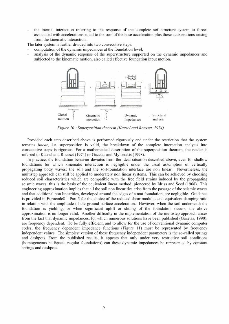
− the inertial interaction referring to the response of the complete soil-structure system to forces associated with accelerations equal to the sum of the base acceleration plus those accelerations arising from the kinematic interaction.
The later system is further divided into two consecutive steps: − computation of the dynamic impedances at the foundation level; − analysis of the dynamic response of the superstructure supported on the dynamic impedances and
subjected to the kinematic motion, also called effective foundation input motion.
Global solution
Kinematic interaction
Dynamic impedances
Structural analysis
Figure 10 : Superposition theorem (Kausel and Roesset, 1974)
Provided each step described above is performed rigorously and under the restriction that the system
remains linear, i.e. superposition is valid, the breakdown of the complete interaction analysis into consecutive steps is rigorous. For a mathematical description of the superposition theorem, the reader is referred to Kausel and Roesset (1974) or Gazetas and Mylonakis (1998).
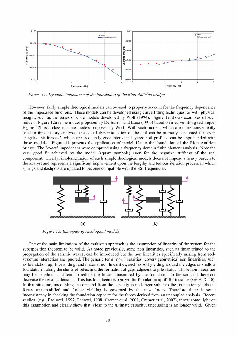
In practice, the foundation behavior deviates from the ideal situation described above, even for shallow foundations for which kinematic interaction is negligible under the usual assumption of vertically propagating body waves: the soil and the soil-foundation interface are non linear. Nevertheless, the multistep approach can still be applied to moderately non linear systems. This can be achieved by choosing reduced soil characteristics which are compatible with the free field strains induced by the propagating seismic waves: this is the basis of the equivalent linear method, pioneered by Idriss and Seed (1968). This engineering approximation implies that all the soil non linearities arise from the passage of the seismic waves and that additional non linearities, developed around the edges of a mat foundation, are negligible. Guidance is provided in Eurocode8 – Part 5 for the choice of the reduced shear modulus and equivalent damping ratio in relation with the amplitude of the ground surface acceleration. However, when the soil underneath the foundation is yielding, or when significant uplift or sliding of the foundation occurs, the above approximation is no longer valid. Another difficulty in the implementation of the multistep approach arises from the fact that dynamic impedances, for which numerous solutions have been published (Gazetas, 1990), are frequency dependent. To be fully efficient, and to allow for the use of conventional dynamic computer codes, the frequency dependent impedance functions (Figure 11) must be represented by frequency independent values. The simplest version of these frequency independent parameters is the so-called springs and dashpots. From the published results, it appears that only under very restrictive soil conditions (homogeneous halfspace, regular foundations) can these dynamic impedances be represented by constant springs and dashpots.
9
0.E+00
2.E+06
4.E+06
6.E+06
8.E+06
1.E+07
0 1 2 3 4
Frequency (Hz)
Das
hpot
(MN
-s/m
)
5
ModelFinite element analysis
-1.E+08
-5.E+07
0.E+00
5.E+07
1.E+08
0 1 2 3 4 5
Frequency (Hz)
Stiff
ness
(MN
/m)
ModelFinite element analysis
Figure 11: Dynamic impedance of the foundation of the Rion Antirion bridge
However, fairly simple rheological models can be used to properly account for the frequency dependence
of the impedance functions. These models can be developed using curve fitting techniques, or with physical insight, such as the series of cone models developed by Wolf (1994). Figure 12 shows examples of such models: Figure 12a is the model proposed by De Barros and Luco (1990) based on a curve fitting technique; Figure 12b is a class of cone models proposed by Wolf. With such models, which are more conveniently used in time history analyses, the actual dynamic action of the soil can be properly accounted for; even "negative stiffnesses", which are frequently encountered in layered soil profiles, can be apprehended with those models. Figure 11 presents the application of model 12a to the foundation of the Rion Antirion bridge. The "exact" impedances were computed using a frequency domain finite element analysis. Note the very good fit achieved by the model (square symbols) even for the negative stiffness of the real component. Clearly, implementation of such simple rheological models does not impose a heavy burden to the analyst and represents a significant improvement upon the lengthy and tedious iteration process in which springs and dashpots are updated to become compatible with the SSI frequencies.
(a) (b) Figure 12: Examples of rheological models
One of the main limitations of the multistep approach is the assumption of linearity of the system for the
superposition theorem to be valid. As noted previously, some non linearities, such as those related to the propagation of the seismic waves, can be introduced but the non linearities specifically arising from soil-structure interaction are ignored. The generic term "non linearities" covers geometrical non linearities, such as foundation uplift or sliding, and material non linearities, such as soil yielding around the edges of shallow foundations, along the shafts of piles, and the formation of gaps adjacent to pile shafts. Those non linearities may be beneficial and tend to reduce the forces transmitted by the foundation to the soil and therefore decrease the seismic demand. This has long been recognized for foundation uplift for instance (see ATC 40). In that situation, uncoupling the demand from the capacity is no longer valid: as the foundation yields the forces are modified and further yielding is governed by the new forces. Therefore there is some inconsistency in checking the foundation capacity for the forces derived from an uncoupled analysis. Recent studies, (e.g., Paolucci, 1997, Pedretti, 1998, Cremer et al, 2001, Cremer et al, 2002), throw some light on this assumption and clearly show that, close to the ultimate capacity, uncoupling is no longer valid. Given
10
the PBD criteria, this is typically the situation faced for the foundation of the Rion-Antirion bridge. Therefore it was decided to implement a more realistic approach which closely reflects the physics of the interaction. Since numerous parametric studies are necessary for the design, a global dynamic non linear soil finite element model is not the proper tool.
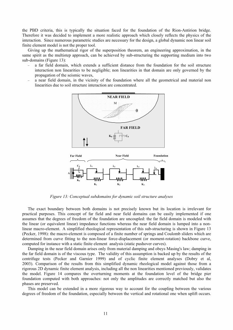
Giving up the mathematical rigor of the superposition theorem, an engineering approximation, in the same spirit as the multistep approach, can be achieved by sub-structuring the supporting medium into two sub-domains (Figure 13):
− a far field domain, which extends a sufficient distance from the foundation for the soil structure interaction non linearities to be negligible; non linearities in that domain are only governed by the propagation of the seismic waves,
− a near field domain, in the vicinity of the foundation where all the geometrical and material non linearities due to soil structure interaction are concentrated.
A
λ4 λ3 λ2 λ1 C0
Foundation Near Field Far Field
K0 K1 K2 K3
NEAR FIELD
M
FAR FIELD
θ
K0 C0
Figure 13: Conceptual subdomains for dynamic soil structure analyses
The exact boundary between both domains is not precisely known but its location is irrelevant for
practical purposes. This concept of far field and near field domains can be easily implemented if one assumes that the degrees of freedom of the foundation are uncoupled: the far field domain is modeled with the linear (or equivalent linear) impedance functions whereas the near field domain is lumped into a non-linear macro-element. A simplified rheological representation of this sub-structuring is shown in Figure 13 (Pecker, 1998): the macro-element is composed of a finite number of springs and Coulomb sliders which are determined from curve fitting to the non-linear force-displacement (or moment-rotation) backbone curve, computed for instance with a static finite element analysis (static pushover curves).
Damping in the near field domain arises only from material damping and obeys Masing's law; damping in the far field domain is of the viscous type. The validity of this assumption is backed up by the results of the centrifuge tests (Pecker and Garnier 1999) and of cyclic finite element analyses (Dobry et al, 2003). Comparison of the results from this simplified dynamic rheological model against those from a rigorous 2D dynamic finite element analysis, including all the non linearities mentioned previously, validates the model. Figure 14 compares the overturning moments at the foundation level of the bridge pier foundation computed with both approaches: not only the amplitudes are correctly matched but also the phases are preserved.
This model can be extended in a more rigorous way to account for the coupling between the various degrees of freedom of the foundation, especially between the vertical and rotational one when uplift occurs.
11
In its more complete form the macro-element model couples all the degrees of freedom (vertical displacement, horizontal displacement and rotation) (Cremer et al, 2001).
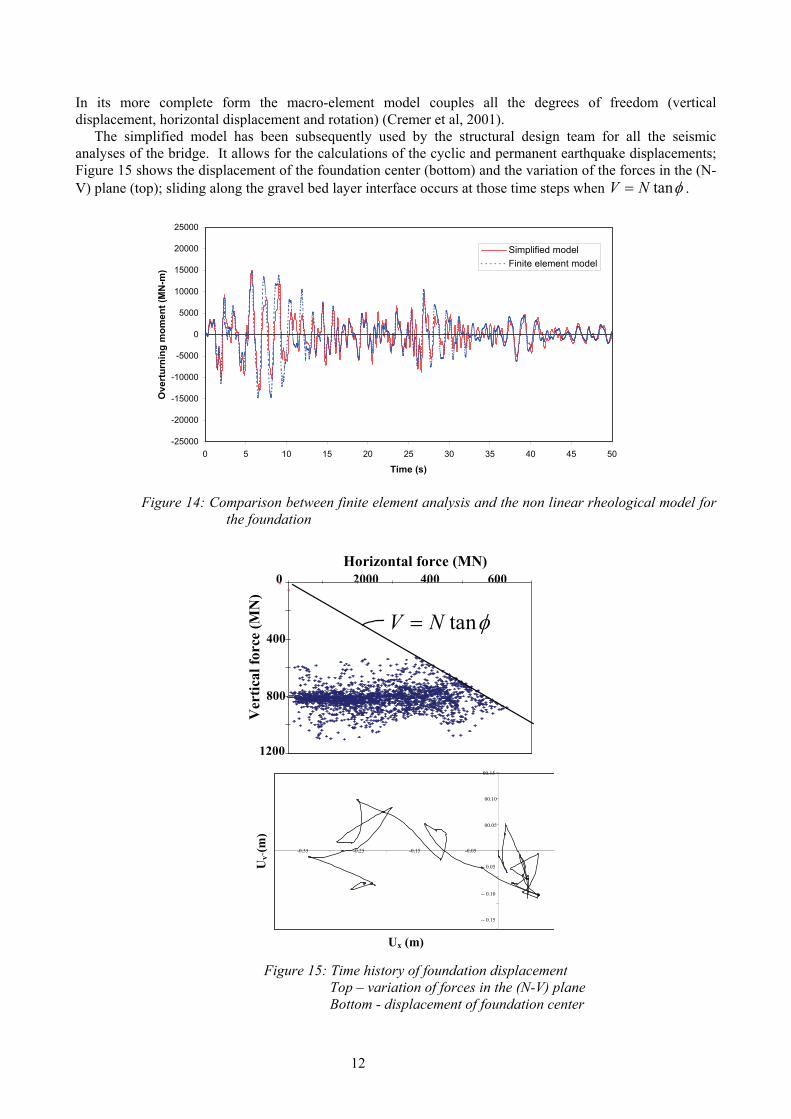
The simplified model has been subsequently used by the structural design team for all the seismic analyses of the bridge. It allows for the calculations of the cyclic and permanent earthquake displacements; Figure 15 shows the displacement of the foundation center (bottom) and the variation of the forces in the (N-V) plane (top); sliding along the gravel bed layer interface occurs at those time steps when tanV N φ= .
-25000
-20000
-15000
-10000
-5000
0
5000
10000
15000
20000
25000
0 5 10 15 20 25 30 35 40 45 50
Time (s)
Ove
rtur
ning
mom
ent (
MN
-m)
Simplified modelFinite element model
Figure 14: Comparison between finite element analysis and the non linear rheological model for
the foundation
Ver
tical
forc
e (M
N)
1200
800
400
0 2000 600 400 0 0
V
H = V tg φ
Horizontal force (MN)
tanV N φ=
) (m
Uy
-- 0.15
-- 0.10
-- 0.05
00.05
00.10
00.15
-0.35 -0.25 -0.15 -0.05
Ux
y
Ux (m)
Figure 15: Time history of foundation displacement Top – variation of forces in the (N-V) plane Bottom - displacement of foundation center
12
The seismically induced forces computed at the foundation level are equal to 500-600MN for the shear
force and to 18 000-20 000MNm for the overturning moment for a vertical (buoyant) weight of 705MN.
BEARING CAPACITY FOR SHALLOW FOUNDATIONS
In the state of practice, once the forces transmitted to the soil by the foundation are determined, the design engineer must check that these forces can be safely supported: the foundation must not experience a bearing capacity failure or excessive permanent displacements. At this point a major difference appears between static, permanently acting loads, and seismic loads. In the first instance excessive loads generate a general foundation failure whereas seismic loads, which by nature vary in time, may induce only permanent irrecoverable displacements. Failure can therefore no longer be defined as a situation in which the safety factor becomes less than unity; it must rather be defined with reference to excessive permanent displacements which impede the proper functioning of the structure; the correct definition of “failure” requires the implementation of a displacement based design approach (DBD). Although this definition seems rather simple and the methodology has been successfully applied to dam engineering (Newmark, 1965), its implementation in a code format is far from an easy task. One of the difficulties is to define the acceptable displacements of the structure in relation to the required performance. Another difficulty obviously lies in the uncertainty linked to the estimation of permanent displacements. Fundamental Requirement of Code Approaches
As an example of code documentation Eurocode 8 states that "The bearing capacity of the foundation shall be verified under a combination of applied action effects NED, VED and MED”. Guidance is provided in an annex that allows checking the bearing capacity taking into account load inclination and eccentricity arising from the inertia forces of the structure as well as the possible effects of the inertia forces in the supporting soil itself.
More specifically, according to the code the design engineer is required to check the following general inequality: dS Rd≤ (1)
where Sd is the seismic design action and Rd the system design resistance. These two terms are explained below.
The design action represents the set of forces acting on the foundations. For the bearing capacity problem, they are composed of the normal force NED, shear force VED, overturning moment MED and soil inertia forces F developed in the soil. The actions NED, VED and MED arise from the inertial soil-structure interaction. The inertia force, F = ρ a (ρ mass density, a acceleration), arises from the site response analysis and kinematic interaction. The term design action is used to reflect that these forces must take into account the actual forces transmitted to the foundation i.e. including any behavior and over-strength factors used in inelastic design.
The design resistance represents the bearing capacity of the foundation; it is a function of the soil strength, soil-foundation interface strength and system geometry (for instance foundation width and length).
Obviously, inequality (1) must include some safety factors. One way is to introduce partial safety factors, as in Eurocode 8. This is not the only possibility and some other codes, like the New Zealand one, choose the Load and Resistance Factored Method (LRFD) and factor the loads and resistance (Pender, 1999). The Eurocode approach is preferred because it gives more insight in the philosophy of safety; on the other hand it requires more experimental data and numerical analyses to calibrate the partial safety factors.
With the introduction of partial safety factors inequality (1) is modified as follows:
( )m
1 strength parametersactions ,geometryd F dRD
S Rγγ γ
⎛ ⎞⋅ ≤ ⎜
⎝ ⎠⎟ (2)
13
where "actions" represent the design action and "strength" the material strength (soil cohesion and /or
friction angle, soil-foundation friction coefficient). γF is the load factor applied to the design action: γF is larger than one for unfavorable actions and smaller than
1.0 for favorable ones. γm is the material safety factor used to reflect the variability and uncertainty in the determination of the soil
strength. In Eurocode 8, the following values are used: 1.4 on the undrained shear strength and cohesion and 1.25 on the tangent of the soil friction angle or interface friction coefficient.
γRd is a model factor. It acts like the inverse of a strength reduction factor applied to the resistance in an LRFD code. This factor reflects the fact, that to evaluate the system resistance some approximations must be made: a theoretical framework must be developed to compute the resistance and like any model it involves simplifications, and assumptions which deviate from reality. It will be seen later on that the model factor is essential and can be used with benefit to differentiate a static problem from a seismic one.
A “static” failure condition is reached when inequality (2) is no longer satisfied. To differentiate between
permanent and time varying loads, advantage can be taken of the model factor γRd to allow for design actions larger than resistance and development of associated permanent displacements. Obviously, the greater the actions exceed the resistance the larger the displacements. This can be expressed mathematically by writing that for such situations:
dS dRλ= (3)
with λ > 1; λ = 1 corresponds to the onset of permanent displacements.
A comparison of equation (3) to equation (2) shows that permanent displacements will take place when the model factor γRd is smaller than 1.0. Therefore, γRd can be used, in addition to reflecting the uncertainties in the model, to relax the constraint that at any time the resistance shall be larger than the action. Provided the model factor is properly calibrated, PBD can be implemented without further change to the overall format of the code.
This approach has been implemented in Eurocode 8 and the tentative values proposed in its Annex F are intended to allow for the development of small permanent displacements in potentially non dangerous materials (medium to dense sand, non sensitive clay). These values range from 1.0 (medium dense to dense sands, non sensitive clays) to 1.5 (loose saturated sands) with intermediate values of 1.15 for loose dry sands. If this phenomenon were disregarded, γRd values would always be larger than 1.0 (in the range 1.2 to 1.5).
Theoretical Framework for the Pseudo-Static Bearing Capacity
The bearing capacity formula proposed in annex F of EC8 to check the seismic bearing capacity of shallow foundations is based on numerous studies that have been initiated in France and Europe with the objective of providing general solutions (Pecker and Salençon, 1991, Dormieux and Pecker, 1995, Salençon and Pecker, 1994 a-b, Paolucci and Pecker, 1997, PREC8, 1996). The solutions were developed within the framework of the yield design theory (Salençon, 1983, 1990): the loading parameters N, V, M and F are considered as independent loading parameters, thereby allowing for any combination of actions to be analyzed; many different kinematic mechanisms (upper bound solutions) are investigated and lower bound solutions are also derived to (i) obtain the best possible approximation to the bearing capacity, (ii) bracket the true value to obtain a quantitative measure of the goodness of the solution. It is interesting to note that the results have been later completed by additional lower bound solutions which confirm the merit of the upper bound solutions and help to narrow the gap between upper and lower bound solutions (Ukritchon et al, 1998). Finally the results, mainly based on the upper bound solutions are cast in the general format (Pecker, 1997): ( ), , , 0N V M Fφ ≤ (4)
14
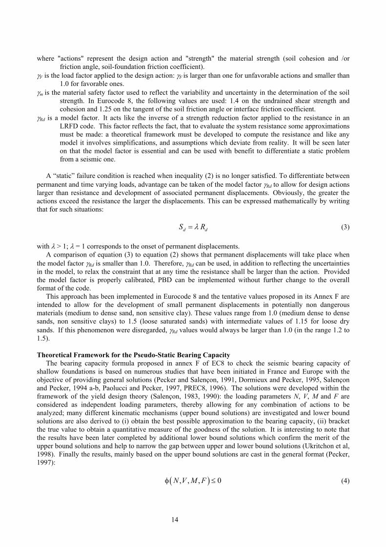
where φ ( ) = 0 (Figure 16) defines in the loading parameters space the equation of a bounding surface. Inequality (4) expresses the fact that any combination of the loading parameters lying outside the surface
corresponds to an unstable situation; any combination lying inside the bounding surface corresponds to a potentially stable situation. The word potentially is used to point out that no assurance can be given since the solutions were derived from upper bound solutions. Indication on the merit of the solutions is obtained by comparison with the lower bound solutions and the model factor of equation (2) is introduced to account for that uncertainty. The uncertainty is twofold: the solution is obtained from an upper bound approach and, although various kinematic mechanisms were investigated, their number remains necessarily limited when a comprehensive implementation of the upper bound theorem would require that all the conceivable mechanisms be investigated.
These results are put in a simple mathematical expression and implemented in the current version of Eurocode 8 (Annex F) and are applicable to cohesive and purely frictional materials.
( ) ( )
( ) ( )( ) ( )
( ) ( )
'
' 'k
1 1 1 0
1 1
T T M Mc c c c
bk ka c k
eF V f F M
N mF N N mF N
β γ− −d+ − ≤
⎡ ⎤ ⎡ ⎤− − − −⎢ ⎥ ⎢ ⎥
⎣ ⎦ ⎣ ⎦
(5)
where: max
RD EDNNN
γ= ,
max
RD EDVVNγ
= , max N
RD EDMMBγ
= .
Nmax is the ultimate bearing capacity of the foundation under a vertical centered load, NED, VED, and MED
are the design action effects at the foundation level, B the foundation width, and γRd the material factor. The soil inertia forces are accounted for by the normalized parameter F equal to / uaB cρ for cohesive soils and to / tana g φ for frictional soils. The other parameters entering equation (5) are numerical parameters derived by curve fitting to the "exact" bearing capacity, the values of which can be found in Pecker (1997) and Eurocode 8 Part 5.
Figure 16: Bounding surface for cohesive soils
Application to the Rion Antirion bridge
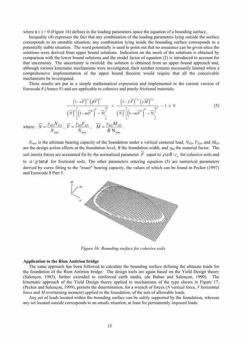
The same approach has been followed to calculate the bounding surface defining the ultimate loads for the foundation of the Rion Antirion bridge. The design tools are again based on the Yield Design theory (Salençon, 1983), further extended to reinforced earth media, (de Buhan and Salençon, 1990). The kinematic approach of the Yield Design theory applied to mechanisms of the type shown in Figure 17, (Pecker and Salençon, 1999), permits the determination, for a wrench of forces (N vertical force, V horizontal force and M overturning moment) applied to the foundation, of the sets of allowable loads.
Any set of loads located within the bounding surface can be safely supported by the foundation, whereas any set located outside corresponds to an unsafe situation, at least for permanently imposed loads.
15
Ω
ω
B
λ Β
ε''α μ
δ
F
Figure 17: Kinematic mechanism
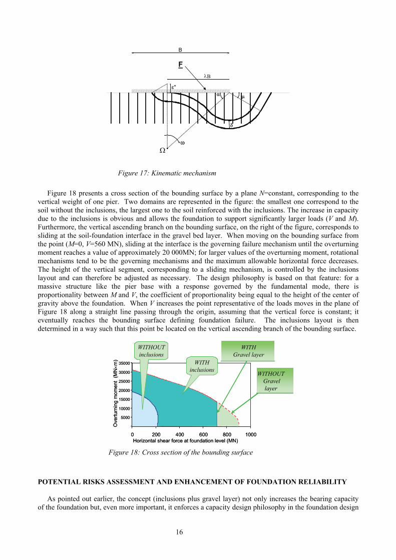
Figure 18 presents a cross section of the bounding surface by a plane N=constant, corresponding to the
vertical weight of one pier. Two domains are represented in the figure: the smallest one correspond to the soil without the inclusions, the largest one to the soil reinforced with the inclusions. The increase in capacity due to the inclusions is obvious and allows the foundation to support significantly larger loads (V and M). Furthermore, the vertical ascending branch on the bounding surface, on the right of the figure, corresponds to sliding at the soil-foundation interface in the gravel bed layer. When moving on the bounding surface from the point (M=0, V=560 MN), sliding at the interface is the governing failure mechanism until the overturning moment reaches a value of approximately 20 000MN; for larger values of the overturning moment, rotational mechanisms tend to be the governing mechanisms and the maximum allowable horizontal force decreases. The height of the vertical segment, corresponding to a sliding mechanism, is controlled by the inclusions layout and can therefore be adjusted as necessary. The design philosophy is based on that feature: for a massive structure like the pier base with a response governed by the fundamental mode, there is proportionality between M and V, the coefficient of proportionality being equal to the height of the center of gravity above the foundation. When V increases the point representative of the loads moves in the plane of Figure 18 along a straight line passing through the origin, assuming that the vertical force is constant; it eventually reaches the bounding surface defining foundation failure. The inclusions layout is then determined in a way such that this point be located on the vertical ascending branch of the bounding surface.
200 400 600 800 1000Horizontal shear force at foundation level (MN)
0
5000
10000
15000
20000
25000
30000
35000
0
Ove
rturn
ing
mom
ent
(MN×m
)
WITHOUTinclusions
WITHinclusions WITHOUT
Gravellayer
WITHGravel layer
200 400 600 800 1000Horizontal shear force at foundation level (MN)
0
5000
10000
15000
20000
25000
30000
35000
0
Ove
rturn
ing
mom
ent
(MN×m
)
WITHOUTinclusions
WITHinclusions WITHOUT
Gravellayer
WITHOUTGravellayer
WITHOUTGravellayer
WITHGravel layer
WITHGravel layer
Figure 18: Cross section of the bounding surface
POTENTIAL RISKS ASSESSMENT AND ENHANCEMENT OF FOUNDATION RELIABILITY
As pointed out earlier, the concept (inclusions plus gravel layer) not only increases the bearing capacity of the foundation but, even more important, it enforces a capacity design philosophy in the foundation design
16
(Pecker, 1998) and improves significantly the reliability of the foundation (item (vii), assessment of potential risks). The gravel layer is equivalent to the "plastic hinge" where inelastic deformation and energy dissipation take place and the "overstrength" is provided by the ground reinforcement which prevents the development of deep seated failure mechanisms involving rotational failure modes of the foundation. These rotational failure modes would be very detrimental to the high rise pylon (230m). If the design seismic forces were exceeded the "failure" mode would be pure sliding at the gravel-foundation interface; this "failure mechanism" can be accommodated by the bridge, which is designed for much larger tectonic displacements than the permanent seismically induced ones. The concept is also somehow similar to a base isolation system with a limitation of the forces transmitted to the superstructure whenever sliding occurs. This limitation is achieved with an adequate choice of the friction angle for the gravel-concrete; its counterpart is the occurrence of permanent displacements which must satisfy the PBD criteria adopted.
DESIGN METHODOLOGY Because of the innovative concept and therefore of its lack of precedence in seismic areas, its justification
calls for the development of new design tools and extensive validation. A very efficient three stages process was implemented to this end: • Development of design tools based on a limit analysis theory to estimate the ultimate capacity of the
foundation system and to define the inclusions layout: length and spacing. As any limit analysis method, this tool cannot give any indication on the induced displacements and rotations.
• Verification of the final layout with a non linear two, or three, dimensional finite element analysis. These analyses provide not only a check of the ultimate capacity but also the non linear stress strain behavior of the foundation and the parameters for the dynamic macro element that will be introduced in the structural model for the seismic calculations of the bridge.
• Experimental verification of the design tools developed in step 1 with centrifuge model tests. As shown below all three approaches give results which are within ±15% of each other, which increases
the confidence in the analyses performed for design.
0
100
200
300
400
500
600
700
0.00 0.05 0.10 0.15 0.20 0.25 0.30
Displacement at foundation level (m)
Horiz
onta
l for
ce (M
N)
M = 50 V
M = 30 V
0
5000
10000
15000
20000
25000
30000
0.0E+00 1.0E-03 2.0E-03 3.0E-03 4.0E-03 5.0E-03
Rotation at foundation level (rd)
Ove
rtur
ning
mom
ent (
MN
-m) M = 50 V
M = 30 V
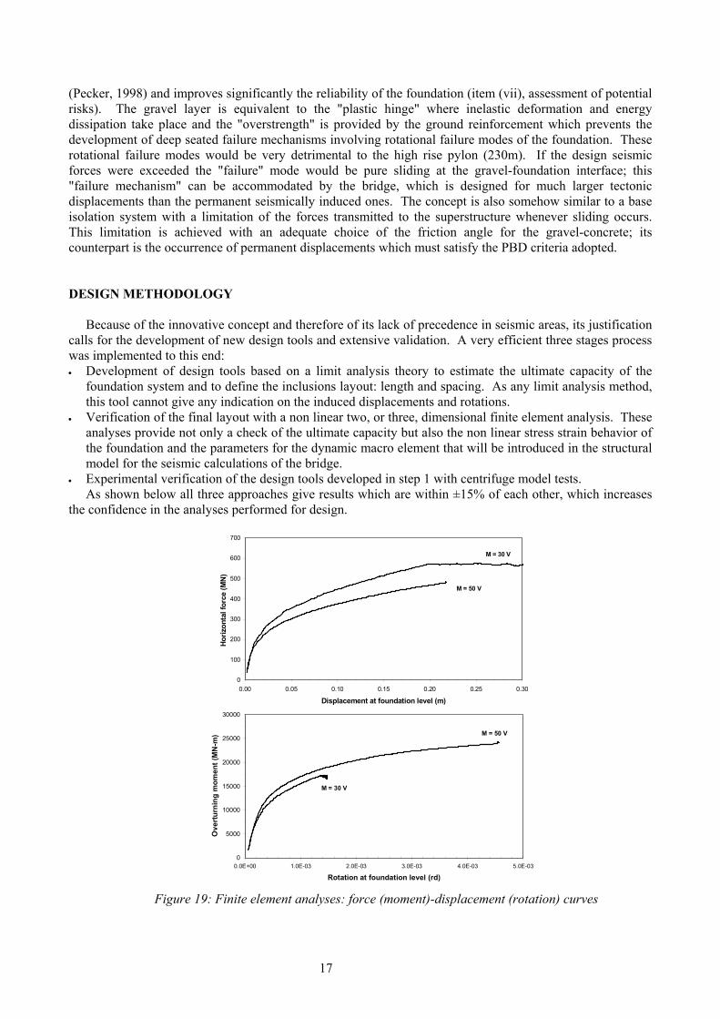
Figure 19: Finite element analyses: force (moment)-displacement (rotation) curves
17
Theoretical and numerical analyses The design tools are based on the Yield design theory as explained above. The displacements are
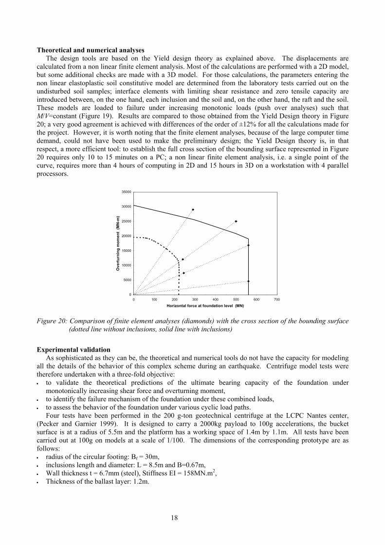
calculated from a non linear finite element analysis. Most of the calculations are performed with a 2D model, but some additional checks are made with a 3D model. For those calculations, the parameters entering the non linear elastoplastic soil constitutive model are determined from the laboratory tests carried out on the undisturbed soil samples; interface elements with limiting shear resistance and zero tensile capacity are introduced between, on the one hand, each inclusion and the soil and, on the other hand, the raft and the soil. These models are loaded to failure under increasing monotonic loads (push over analyses) such that M/V=constant (Figure 19). Results are compared to those obtained from the Yield Design theory in Figure 20; a very good agreement is achieved with differences of the order of ±12% for all the calculations made for the project. However, it is worth noting that the finite element analyses, because of the large computer time demand, could not have been used to make the preliminary design; the Yield Design theory is, in that respect, a more efficient tool: to establish the full cross section of the bounding surface represented in Figure 20 requires only 10 to 15 minutes on a PC; a non linear finite element analysis, i.e. a single point of the curve, requires more than 4 hours of computing in 2D and 15 hours in 3D on a workstation with 4 parallel processors.
0
5000
10000
15000
20000
25000
30000
35000
0 100 200 300 400 500 600 700
Horizontal force at foundation level (MN)
Ove
rtur
ning
mom
ent
(MN
-m)
Figure 20: Comparison of finite element analyses (diamonds) with the cross section of the bounding surface
(dotted line without inclusions, solid line with inclusions)
Experimental validation
As sophisticated as they can be, the theoretical and numerical tools do not have the capacity for modeling all the details of the behavior of this complex scheme during an earthquake. Centrifuge model tests were therefore undertaken with a three-fold objective: • to validate the theoretical predictions of the ultimate bearing capacity of the foundation under
monotonically increasing shear force and overturning moment, • to identify the failure mechanism of the foundation under these combined loads, • to assess the behavior of the foundation under various cyclic load paths.
Four tests have been performed in the 200 g-ton geotechnical centrifuge at the LCPC Nantes center, (Pecker and Garnier 1999). It is designed to carry a 2000kg payload to 100g accelerations, the bucket surface is at a radius of 5.5m and the platform has a working space of 1.4m by 1.1m. All tests have been carried out at 100g on models at a scale of 1/100. The dimensions of the corresponding prototype are as follows: • radius of the circular footing: Bf = 30m, • inclusions length and diameter: L = 8.5m and B=0.67m, • Wall thickness t = 6.7mm (steel), Stiffness EI = 158MN.m2, • Thickness of the ballast layer: 1.2m.
18
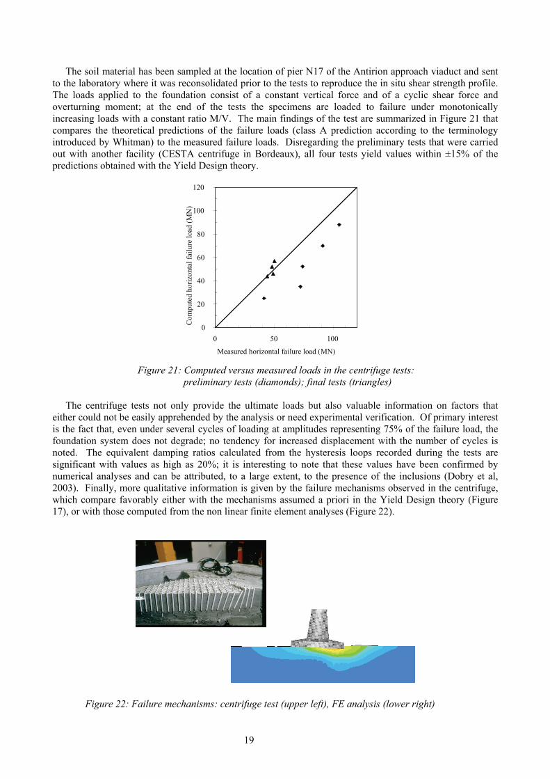
The soil material has been sampled at the location of pier N17 of the Antirion approach viaduct and sent to the laboratory where it was reconsolidated prior to the tests to reproduce the in situ shear strength profile. The loads applied to the foundation consist of a constant vertical force and of a cyclic shear force and overturning moment; at the end of the tests the specimens are loaded to failure under monotonically increasing loads with a constant ratio M/V. The main findings of the test are summarized in Figure 21 that compares the theoretical predictions of the failure loads (class A prediction according to the terminology introduced by Whitman) to the measured failure loads. Disregarding the preliminary tests that were carried out with another facility (CESTA centrifuge in Bordeaux), all four tests yield values within ±15% of the predictions obtained with the Yield Design theory.
0
20
40
60
80
100
120
0 50 100
Measured horizontal failure load (MN)
Com
pute
d ho
rizon
tal f
ailu
re lo
ad (M
N)
Figure 21: Computed versus measured loads in the centrifuge tests:
preliminary tests (diamonds); final tests (triangles) The centrifuge tests not only provide the ultimate loads but also valuable information on factors that
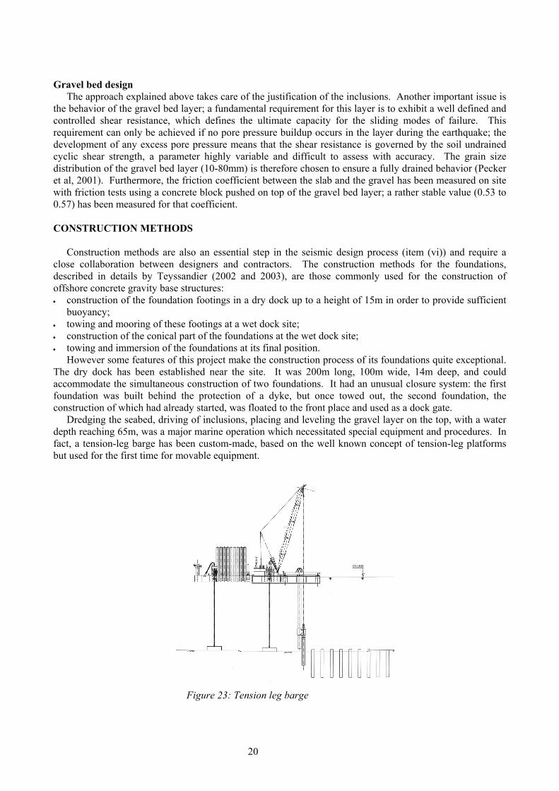
either could not be easily apprehended by the analysis or need experimental verification. Of primary interest is the fact that, even under several cycles of loading at amplitudes representing 75% of the failure load, the foundation system does not degrade; no tendency for increased displacement with the number of cycles is noted. The equivalent damping ratios calculated from the hysteresis loops recorded during the tests are significant with values as high as 20%; it is interesting to note that these values have been confirmed by numerical analyses and can be attributed, to a large extent, to the presence of the inclusions (Dobry et al, 2003). Finally, more qualitative information is given by the failure mechanisms observed in the centrifuge, which compare favorably either with the mechanisms assumed a priori in the Yield Design theory (Figure 17), or with those computed from the non linear finite element analyses (Figure 22).
Figure 22: Failure mechanisms: centrifuge test (upper left), FE analysis (lower right)
19
Gravel bed design
The approach explained above takes care of the justification of the inclusions. Another important issue is the behavior of the gravel bed layer; a fundamental requirement for this layer is to exhibit a well defined and controlled shear resistance, which defines the ultimate capacity for the sliding modes of failure. This requirement can only be achieved if no pore pressure buildup occurs in the layer during the earthquake; the development of any excess pore pressure means that the shear resistance is governed by the soil undrained cyclic shear strength, a parameter highly variable and difficult to assess with accuracy. The grain size distribution of the gravel bed layer (10-80mm) is therefore chosen to ensure a fully drained behavior (Pecker et al, 2001). Furthermore, the friction coefficient between the slab and the gravel has been measured on site with friction tests using a concrete block pushed on top of the gravel bed layer; a rather stable value (0.53 to 0.57) has been measured for that coefficient. CONSTRUCTION METHODS
Construction methods are also an essential step in the seismic design process (item (vi)) and require a close collaboration between designers and contractors. The construction methods for the foundations, described in details by Teyssandier (2002 and 2003), are those commonly used for the construction of offshore concrete gravity base structures: • construction of the foundation footings in a dry dock up to a height of 15m in order to provide sufficient
buoyancy; • towing and mooring of these footings at a wet dock site; • construction of the conical part of the foundations at the wet dock site; • towing and immersion of the foundations at its final position.
However some features of this project make the construction process of its foundations quite exceptional. The dry dock has been established near the site. It was 200m long, 100m wide, 14m deep, and could accommodate the simultaneous construction of two foundations. It had an unusual closure system: the first foundation was built behind the protection of a dyke, but once towed out, the second foundation, the construction of which had already started, was floated to the front place and used as a dock gate.
Dredging the seabed, driving of inclusions, placing and leveling the gravel layer on the top, with a water depth reaching 65m, was a major marine operation which necessitated special equipment and procedures. In fact, a tension-leg barge has been custom-made, based on the well known concept of tension-leg platforms but used for the first time for movable equipment.
Figure 23: Tension leg barge
20
This concept was based on active vertical anchorage to dead weights lying on the seabed (Figure 23). The tension in these vertical anchor lines was adjusted in order to give the required stability to the barge with respect to sea movements and loads handled by the crane fixed on its deck. By increasing the tension in the anchor lines, the buoyancy of the barge allowed the anchor weights to be lifted from the seabed, and then the barge, including its weights, could be floated away to a new position.
As already stated, once completed the foundations are towed then sunk at their final position. Compartments created in the footings by the radial beams can be used to control tilt by differential ballasting. Then the foundations are filled with water to accelerate settlements. This pre-loading was maintained during pier shaft and pier head construction, thus allowing a correction for potential differential settlements before erecting pylons.
The deck of the main bridge is erected using the balance cantilever technique, with prefabricated deck elements 12m long comprising also their concrete slab (another unusual feature). ACKNOWLEDGMENTS
The ideas and results presented in this lecture are the results of long term collaboration with many colleagues; the author is particularly indebted to Pr J. Salençon for his everlasting guidance, to R. Paolucci, P. de Buhan and L. Dormieux for their contribution and to G. Gazetas for fruitful discussions.
For the application to the Rion Antirion bridge, the development of this original foundation concept was made possible thanks to the full cooperation between all the parties involved in the project: the Concessionaire (Gefyra SA), the Contractor (Gefyra Kinopraxia), the Design JV and the Design Checker (Buckland & Taylor Ltd). The author is indebted to Mr. Teyssandier from Gefyra SA, Mr. De Maublanc and Morand from Gefyra Kinopraxia, Mr. Tourtois from the Design JV and Dr. Taylor for their collaboration and confidence. He also wishes to specially thank Dr. Peck, Dr. Dobry and Dr. Gohl, consultants to the Checker, for their invaluable contribution through their constant willingness to help him clarify and develop the concept.
More information on the project can be found on the web site www.gefyra.gr. REFERENCES Applied Technology Council (1996). "ATC 40 : The seismic evaluation and retrofit of concrete buildings".
2 volumes. Redwood City CA. Cremer, C., Pecker, A., Davenne, L. (2001). "Cyclic macro-element for soil structure interaction - Material
and geometrical non linearities". Num. Methods in Geomech., 25, 1257-1284. Cremer, C., Pecker, A., Davenne, L. (2002). "Modelling of non linear dynamic behaviour of a shallow strip
foundation with macro-element." J. of Earthq. Eng., 6(2), 175-212. De Barros, F.C., Luco, E. (1990). "Discrete models for vertical vibrations of surface and embedded
foundations". Earthquake Engineering and Structural Dynamics, vol. 19. de Buhan, P., Salençon, J. (1990). "Yield strength of reinforced soils as anisotropic media." in Yielding,
Damage and Failure of Anisotropic Solids; EGF5, Mechanical Engineering Publications, London. Dobry, R., Pecker, A., Mavroeidis, G., Zeghal, M., Gohl, B., Yang, D. (2003). "Damping/Global Energy
Balance in FE Model of Bridge Foundation Lateral Response." J. of Soil Dynamics and Earthq. Eng., 23(6), 483-495.
Dormieux, L., Pecker, A. (1995). "Seismic bearing capacity of a foundation on a cohesionless soil". Journal of Geotechnical Engineering, ASCE, Vol 121, pp 300-303.
Eurocode 8-Part 5 (2003). "Foundations, retaining structures and geotechnical aspects". EN 1998-5. Gazetas, G. (1990). "Foundation vibration". Foundation Engineering Handbook, Chap. 15, 2nd Edition -
Hsai-Yan Fang Eds. Gazetas, G., Mylonakis, G. (1998). "Seismic soil structure interaction: new evidence and emerging issues".
Geotechnical Earthquake Engineering and Soil Dynamics, ASCE, II, pp 1119-1174. Idriss, I.M., Seed, H.B. (1968). "Seismic response of horizontal soil layers". Journal of Soil Mechanics and
Foundation Division, ASCE, vol. 96, N° SM4.
21
Kausel, E., Roesset, J.M. (1974). "Soil Structure Interaction for Nuclear Containment Structures". Proc. ASCE, Power Division Specialty Conference, Boulder, Colorado.
Masing, G. (1926). "Eigensprannung und Verfestigung beim Messing" Proceedings International Congress of Applied Mechanics.
Newmark, N. (1965). "Effects of earthquakes on dams and embankments". Geotechnique, Vol. XV(2), pp 139-160.
Paolucci, R. (1997). "Simplified evaluation of earthquake induced permanent displacement of shallow foundations". Journal of Earthquake Engineering, Vol 1, n°3, pp 563-579.
Paolucci, R., Pecker, A. (1997). "Seismic bearing capacity of shallow strip foundations on dry soils". Soils and Foundation, Vol 37, n°3, pp 95-105.
Pecker A., Salençon J. (1991). "Seismic bearing capacity of shallow strip foundations on clay soils". CENAPRED, Proceedings of the International Workshop on Seismology and Earthquake Engineering, Mexico, pp 287-304.
Pecker, A., Salençon, J., Auvinet, G., Romo, M.P., Verzurra, L. (1995). "Seismic bearing capacity of foundations on soft soils". Final Report to European Commission - Contract CI1 - CT92-0069.
Pecker, A. (1997). "Analytical formulae for the seismic bearing capacity of shallow strip foundation". Seismic Behavior of Ground and Geotechnical Structures, Seco e Pinto Ed., Balkema, 261-268.
Pecker, A. (1998). "Capacity Design Principles For Shallow Foundations In Seismic Areas." Proc. 11th European. Conf.. on Earthq. Eng., A.A. Balkema Publishing.
Pecker, A., Salençon, J. (1999). "Ground Reinforcement In Seismic Area." Proc. of the XI Panamerican Conf. on Soil Mech. and Geotech. Eng., Iguasu, 799-808.
Pecker, A., Garnier, J. (1999). "Use of Centrifuge Tests for the Validation of Innovative Concepts in Foundation Engineering." Proc. 2nd Int. Conf. on Earthq. Geotech. Eng., Lisbon, 433-439.
Pecker, A., Pender, M. (2000). "Earthquake resistant design of foundations: new constructions". GeoEng2000; Vol 1: Invited paper. 313-332.
Pecker, A., Prevost, J.H., Dormieux, L. (2001). "Analysis of pore pressure generation and dissipation in cohesionless materials during seismic loading." J. of Earthq. Eng., 5(4), 441-464.
Pedretti, S. (1998). "Nonlinear seismic soil-foundation interaction: analysis and modelling method". PhD Thesis Dpt Ing Structurale, Politecnico di Milano.
Pecker, A. (2003). “Aseismic foundation design process - Lessons learned from two major projects : the Vasco da Gama and the Rion-Antirion bridges”. Proc. 5th ACI International Conference on Seismic Bridge Design and Retrofit for Earthquake Resistance, La Jolla, California.
Pender, M. (1993). "Aseismic Pile Foundation design Analysis". Bulletin of the New Zealand National Society for Earthquake Engineering, Vol. 26, No 1, 49-160.
Pender, M.J. (1995). "Earthquake Resistant design of Foundations". Keynote address Pacific Conference on Earthquake Engineering, PCEE95, Melbourne.
Pender, M.J. (1999). "Geotechnical Earthquake Engineering design practice in New-Zealand". Proceedings of the 2nd International Conference on Earthquake Geotechnical Engineering. Sêco e Pinto Ed., Balkema.
PREC 8 (1996). (Prenormative Research in Support of Eurocode 8) "Seismic behavior and design of foundation and retaining structures". Facioli-Paolucci Eds., Report n°2.
Salençon, J. (1983). Calcul à la rupture et analyse limite Presses de l'Ecole Nationale des Ponts et Chaussées, Paris.
Salençon, J. (1990). “An introduction to the yield design theory and its application to soil mechanics". European Journal of Mechanics A/Solids, Vol 9(5), 477-500.
Salençon, J., Pecker A. (1994a). "Ultimate bearing capacity of shallow foundations under inclined and eccentric loads. Part 1: Purely cohesive soil". European Journal of Mechanics A/Solids, 14, n° 3, 349-375.
Salençon, J., Pecker, A. (1994b). "Ultimate bearing capacity of shallow foundations under inclined and eccentric loads. Part II: Purely cohesive soil without tensile strength". European Journal of Mechanics A/Solids, 14, n° 3, 377-396.
Teyssandier, J.P., Combault, J., Pecker, A. (2000). "Rion Antirion: le pont qui défie les séismes." La Recherche, 334, 42-46.
Teyssandier, J.P. (2002). "Corinthian Crossing." Civil Engineering, 72(10), 43 -49. Teyssandier, J.P. (2003). "The Rion-Antirion bridge, Design and construction." ACI International
Conference on Seismic Bridge Design and Retrofit. La Jolla, California.
22

Ukritchon, B., Whittle, A.J., Sloan, S.W. (1998). "Undrained limit analysis for combined loading of strip footings on clay". Journal of Geotechnical and Geoenvironmental Engineering, March, 265-275.
Wolf, J.P. (1994). Foundation vibration analysis using simple physical models. Prentice Hall Inc.
23