enhanced machine controller architecture overview · enhanced machine controller architecture...
TRANSCRIPT
Enhanced MachineController ArchitectureOverview
NISTIR 5331
Frederick M . ProctorSystems Integration Group
John MichaloskiIntelligent Controls Group
U.S . DEPARTMENT OF COMMERCETechnology AdministrationNational Institute of Standardsand TechnologyRobot Systems DivisionBldg. 220 Rm. B124Gaithersburg, MD 20899
December 1993
U.S. DEPARTMENT OF COMMERCERonald H. Brown, Secretary
TECHNOLOGY ADMINISTRATIONMary L Good, Under Secretary for Technology
NATIONAL INSTITUTE OF STANDARDSAND TECHNOLOGYArati Prabhakay Director

ENHANCED MACHINECONTROLLER
ARCHITECTUREOVERVIEW
Fred ProctorJohn Michaloski
Manufacturing Engineering Laboratory
National Institute of Standards and Technology
This work was performed by U .S. Government employees aspart of their official duties, and is not subject to copyright .
Enhanced Machine Controller Architecture Overview
1. IntroductionThis overview provides a brief summary of NIST's efforts to define an Enhanced MachineController (EMC) architecture, with emphasis on the requirements of machine tools . The primaryconcern is to implement an open architecture conforming to the Next Generation ControllerSpecification for an Open System Architecture Standard (NGC SOSAS) [1] and to the NIST Real-time Control System reference model architecture (RCS) [2, 3] by defining a set of modules, theirinterfaces, and required basic functionality . The importance of multi-level feedback, "art-to-part"requirements, and sensor-based enhancements will be directly addressed during the developmentof the architecture.Section 2 describes the machine tool hardware and software systems that are being implementedat NIST for the EMC project. This section was included at the beginning of the document so thatthe subsequent discussions could be rooted in real machine control scenarios . Section 3 details thegoals of the EMC project and how the systems being implemented will help meet those goals .Section 4 lists the requirements of users and systems integrators which drive the development ofthe architecture. Section 5 outlines the EMC architecture and its relationships to the existing NISThierarchical control architecture and current industry standardization efforts . Sections 6 through 8detail the modules which make up the controller . Section 9 details the controller infrastructure (the"Virtual Machine"), Section 10 outlines the safety issue, and Section 11 provides a road map forthe subsequent documents that will provide a more complete and detailed description of the EMCarchitecture .Disclaimer: No approval or endorsement of any commercial product by the National Institute ofStandards and Technology is intended or implied . Certain commercial equipment, instruments, ormaterials are identified in this report in order to facilitate understanding . Such identification doesnot imply recommendation or endorsement by the National Institute of Standards and Technology,nor does it imply that the materials or equipment identified are necessarily the best available forthe purpose .
2. System DescriptionThe EMC controller implementation efforts at NIST are divided between two platforms, the ShopFloor Controller and the Laboratory Development Controller . The Shop Floor Controller is basedon the PMAC motion controller from Delta Tau Data Systems, in an environmentally-enclosed 486IBM-PC. The 486 is running the Microsoft MS-DOS operating system . This controller isconnected to a Monarch VMC-75 3- 1/2 axis vertical machining center, which has a positioning (W)axis and a tool changer. A VGA monitor, keyboard, and trackball were mounted into an enclosurefor the operator console, replacing the original General Electric Mark Century 2000 controllerconsole. In addition, the control console includes jog buttons, a handwheel, and mode selectswitches. All the Monarch control input and output lines run into a terminal block inside a cabinetat the back of the machine, and are interfaced to the PMAC motion controller using a variety ofinterconnect modules provided by Delta Tau .In the Shop Floor Controller, the host computer is running Delta Tau's PMAC-NC program . Thisprogram provides operator interface functions such as graphics display and control panel input,manages data such as tool offsets and parameter tables which affect axis motion, and manages therotary buffer used to download part programs to the PMAC board . NIST developed graphics "CNCfront ends" for this controller which can emulate either the Fanuc 10, GE 2000, or Allen-Bradley8200 commercial controller interfaces . EIA-274-D part programs are first parsed by the PMAC-NC program, and translated into the PMAC native language . The PMAC board communicates tothe host PC using a dual-ported RAM mechanism . The PMAC board performs the coordinate
3
Enhanced Machine Controller Architecture Overview
system trajectory planning, the axis trajectory interpolation, the servo computations, all of the PLCtasks (selection between Z or W axes, control panel I/O, and tool changer), and axis limit checking .The Laboratory Development Controller is also hosted by a 486 PC, and uses the PMAC motioncontroller as well . However, this system differs in several ways . Most importantly, it is notconnected to a production machine tool, but to a hardware simulator which contains DCservomotors and encoders . This allows development work to proceed without anxiety about injuryor damaging expensive production machinery . The Laboratory Development Controller is runninga real-time Unix operating system which is POSIX [4] compliant, and is controlled by softwarefrom Cimetrix, Inc . Most of the functions performed by the PMAC board in the Shop FloorController are performed in software on the PC host, namely PLC programs, part programinterpretation, and trajectory generation. Both systems are capable of handling EIA-274-Dprograms, which can be generated off-line using a CAD/CAM system . A recent benchmarkdemonstrated both controllers running the NAS-979 "circle diamond square" test part program .
3. Implementation PlanThis document serves as an initial reference for the architecture, module definitions, and interfaceswhich are being prototyped and implemented on both the Shop Floor Controller and LaboratoryDevelopment Controller. Following this document will be the detailed specifications of each of themodules laid out here, whose exact contents will be driven by the lessons learned during theprototyping and implementation phases with both controllers . Implementation and prototypingoccur according to the following plan . Integration of existing enhancements, such as thermalcompensation and part probing, are performed on the Shop Floor Controller, because theseenhancements require actual analysis on the machine tool . Once these enhancements aredemonstrated and hardened, they are ported to the Laboratory Development Controller for"wrapping" as modules which conform to the SOSAS architecture . These wrapped enhancementsare then be demonstrated again on the Monarch for a demonstration of a fully SOSAS-conformantcontroller . Additional investigations which do not require machine tool time are performed on theLaboratory Development Controller from the beginning . Such investigations include the testing ofnew operating systems, CAD/CAM interfaces, and interfaces to the factory .Throughout this document, it should be understood that NIST's role in the EMC is not to act as adeveloper of third-party enhancements, but as a system integrator whose intent is to takeenhancements already developed by third parties, port them to the controller implementations, anddocument the effort required to do this . The result will be a set of interfaces required to make thistask easier on systems integrators.
4. EMC RequirementsThe following sections outline the development of the EMC architecture, using an analysis of therequirements placed on the architecture from several areas .
4.1 Legacy Requirements
The EMC must provide at least the capabilities found in the legacy systems familiar to machiniststoday. These legacy capabilities, as applicable to the NIST testbed, are :•
three-axis contour milling;•
automatic tool changing ;•
EIA-274-D part program interpretation ;•
presentation of a graphic display typified by that of current controller technology ;
4
Enhanced Machine Controller Architecture Overview
•
"hands on" access by the machinist to physical jog buttons, wheels, and mode selectswitches .
4.2 "Art-to-Part" Requirements
Automatically generating a process plan based on CAD part descriptions obviously requires greatsystem sophistication . For each step in a process plan, tool path planning is responsible fordirecting the machine tool cutter to remove designated volumes of material. The path planninggenerates motion primitives based on these volumes . It must account for proper machine tool setupand fixturing, and account for any fixturing interference. Each motion primitive must betransformed into motion segment trajectories . These segments are then transformed into a series ofset points for the individual axes . At a coarse level of description, the system functionality can beloosely codified by the following breakdown :•
general purpose, such as computer-aided design or user interfacing (e.g ., pendants, touchscreens, or display graphics) ;
•
part design, such as geometric calculation, STEP data handling, or data management ;•
process planning and scheduling;•
elementary machining operations, such as Material Removal Surface Element Volume(MRSEV) or Boundary to B-Rep Conversion functions ;
•
tool path generation, such as NC programming interfaces, NC-code generation, andmachining simulation.
4.3 Feedback Requirements for Adaptive Control and Error Compensation
While the machine tool's axis positions are closed with servo loops, typical NC programs areinterpreted "open loop" with no process feedback for monitoring machining . Error compensation,if done at all, is done statically, by preprogramming instances where one would expect errors andthen compensating for the errors . This is common in today's controllers which use lead screwcompensation tables . Dimensional accuracy and part finish can be improved by incorporatingdynamic closed-loop error compensation techniques, which resolves errors through environmentsensing.One can attach a sensor to the problem area, read real-time sensor feedback, evaluate thisreading against the expected model and then modify the course of action based on any measurederror. Among the types of feedback and error compensation the EMC project will be exploringinclude :•
thermal error compensation•
geometric error compensation•
chatter control•
control algorithm errorOne of the main criticisms of the SOSAS is that it did not grow out of a comprehensive prototypingeffort. The EMC philosophy is to attempt to install the above enhancements to our shop floor andlaboratory development controllers, and to supplement the SOSAS in areas where it says nothingabout how this is to be done .
4.4 Modularity, Portability, Extensibility, and Scalability Requirements
Additional requirements are placed on the controller by users or system integrators who want topiece together their own systems component by component, modify the way their controller doescertain things, apply their modifications to another controller, or start small and upgrade as they
5
6
Enhanced Machine Controller Architecture Overview
grow. These requirements mean that the controller architecture must be modular, extensible,portable, and scalable. Each of these is described in more detail in the following sections .
4.4.1 Modularity
Modularity refers to the ability of controls users and system integrators to purchase and replacecomponents of the controller without unduly affecting the rest of the controller . For the EMC, thismeans the ability to replace hardware boards and peripheral devices such as disks or RAM withequivalent products from another source . The key to doing this is the definition of the moduleswhich make up a controller, their functionality, their interfaces, and the basic controllerinfrastructure (bus, microprocessor, operating system, etc .) which can support the modules . Thefirst three are addressed by the SOSAS but need to be fleshed out and validated ; the infrastructuredefinition is necessarily a choice made by the system integrators, in this case NIST .
4.4.2 Extensibility
Extensibility refers to the ability of knowledgable users and third parties to incrementally addfunctionality to a module without replacing it completely . For example, an extensible planinterpreter would allow users to add statements to the planning language (such as a new G code) .An extensible trajectory generator would allow this G code to be executed, while an extensiblediscrete input/output module would allow the easy addition of a new actuator or sensor .Extensibility is required by NIST for the incorporation of enhancements, but developing moduleswhich contain the "hooks" for extensibility remains the responsibility of module vendors .
4.4.3 Portability
Portability refers to the ease with which a module can be made to run in a controller based onanother platform . Portability normally refers to software source code, which should be compilablefor a variety of CPUs and operating systems. Standards such as ANSI C and POSIX serve as areference to which programmers adhere . For the EMC, portability is mostly an issue left to vendorswith whom NIST is working, since little if any porting effort in the form of source codemodification should be required of machine tool systems integrators .
4.4.4 Scalability
Scalability, like portability, refers to the ease with which a module can be made to run in acontroller based on another platform, but unlike portability, scalability is an attribute of thecontroller architecture, not the implementation of the module. Scalability means that a controllerbased on the architecture may be implemented equally easily by systems integrators entirely insoftware on a fast processor, as a distributed multi-processor bus system, or in a standalone PC .Scalability of the architecture gives system integrators the ability to build controllers around theircustomer's needs and budget, and gives customers the freedom to "scale up" to a higher-performance implementation when their needs and budgets increase. Scalability is provided by theSOSAS, and will be validated in the EMC testbed .
5. EMC ArchitectureThis section provides a summary of the architecture, at a block-diagram level . The evolution of thearchitecture from its basis on the NIST RCS is discussed in the first section . The question of howthe EMC architecture is related to the SOSAS is answered in the second section . The subsequentsections overview the modules which make up the EMC and the nature of the messages that areunderstood by each module .
Enhanced Machine Controller Architecture Overview
5.1 EMC and the NIST Real-time Control System
The EMC architecture is derived from the NIST Real-time Control System reference modelarchitecture (RCS) [2] and NASREM, the NASA/NBS reference model architecture [3] . RCSbuilds upon experience acquired in the Automated Manufacturing Research Facility [5] during the1980's for constructing hierarchies of controllers for machining workcells which include robot,machine tool, and coordinate measuring machines as components . The NASREM reference modelplaces heavy emphasis on teleoperation, and puts a burden on the architecture to support real-timefeedback from a human operator throughout the control hierarchy .The EMC architecture conforms to both the NIST RCS reference model and to the Next GenerationController Specification for an Open System Architecture Standard (NGC SOSAS), which is thespecification resulting from the program sponsored by the U .S . Air Force for standardizingmachine controllers. The NIST and SOSAS models differ mainly in two ways . First,RCS/NASREM specifies control modules that are arranged in a hierarchy, each module having thecapability for closed-loop control ; the SOSAS specifies no such hierarchy for control, although itdoes indicate a hierarchical layering of interfaces to the physical hardware level . Second,RCS/NASREM specifies a higher resolution for the definition of the control modules than does theSOSAS.Since RCS/NASREM is more strict in its definition than is the SOSAS, defining a controllerarchitecture which satisfies both is straightforward: one focuses on the stricter model, deriving anarchitecture whose components are then grouped and labeled according the coarser model . In thediscussions that follow, nomenclature from both RCS/NASREM and the SOSAS will be used, sothat a mapping between them will emerge .
5.2 EMC and the SOSAS
Following the SOSAS, the EMC defines the following Standardized Applications (SAs) :Workstation Planning Standardized Application (WPSA), Workstation Management StandardizedApplication (WMSA), and Controls Standardized Application (CSA) . As prescribed by theSOSAS, the EMC Standardized Applications communicate by passing Neutral ManufacturingLanguage (NML) messages. Communication within a single SA is not governed by the SOSAS,and is not required to use NML . Furthermore, the SOSAS does not place the individual SAs in ahierarchy, nor does it specify the architecture within the SAs other than defining the NMLmessages a particular SA must respond to and what that response should be . However, the SOSASdoes not preclude organizing the SAs hierarchically in a particular implementation, nor does itdisallow further refinement within the SAs. In the EMC, this organization and refinement is doneso that the benefits of the NIST Real-time Control System architecture can be applied to machinecontrol within the broad constraints of the SOSAS . The EMC organization places the WPSA,WMSA, and CSA into a hierarchy, and further refines the CSA into four modules which form abranched hierarchy as specified in RCS/NASREM .We allow for Domain-Independent Applications (DIAs), as prescribed by the SOSAS, which letthird parties enhance a controller by providing a function not present in the off-the-shelf version .The desire to incorporate enhancements as DIAs is a direct driver for an open architecture . DIAscan be a simple as a data logger which accumulates the time each tool has been used, or as complexas model-based thermal compensation. Perhaps the most important DIA is the operator interface,which is not part of the controller per se, but acts as an independent application allowing the userto view the state of the workstation and at times giving one direct control as specified in NASREM.The Virtual Machine comprises the software which interfaces directly to the underlying controllerhardware. The rationale for the VM is that something is needed to insure portability of SAs and
7
Enhanced Machine Controller Architecture Overview
modules across different operating systems and hardware platforms . The bulk of the VM functionsare provided by the underlying operating system (e.g., the file system, process tasking, interruptservicing), but interfaces to these functions require standardization by the VM . The VM furtherstandardizes the additional interfaces to the machine hardware, graphics displays, control panelinterface, and other machine-specific functions.
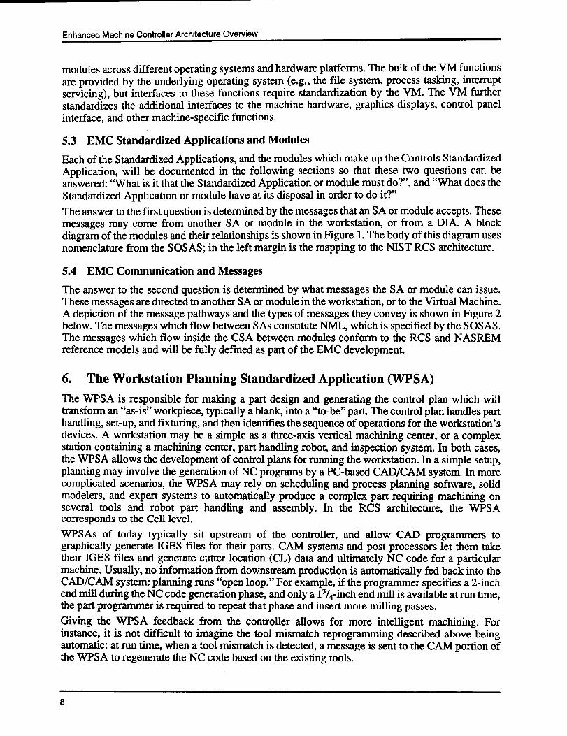
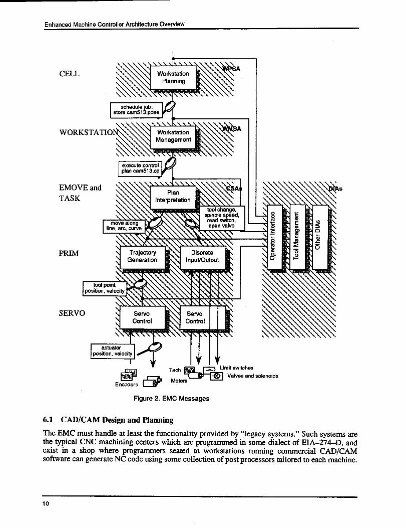
5.3 EMC Standardized Applications and Modules
Each of the Standardized Applications, and the modules which make up the Controls StandardizedApplication, will be documented in the following sections so that these two questions can beanswered: "What is it that the Standardized Application or module must do?", and "What does theStandardized Application or module have at its disposal in order to do it?"The answer to the first question is determined by the messages that an SA or module accepts . Thesemessages may come from another SA or module in the workstation, or from a DIA . A blockdiagram of the modules and their relationships is shown in Figure 1 . The body of this diagram usesnomenclature from the SOSAS ; in the left margin is the mapping to the NIST RCS architecture .
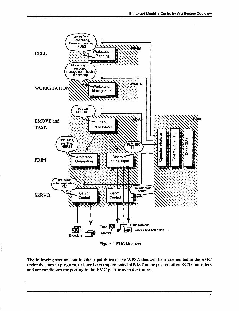
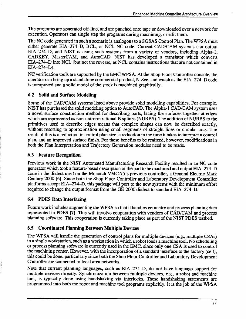
5.4 EMC Communication and Messages
The answer to the second question is determined by what messages the SA or module can issue .These messages are directed to another SA or module in the workstation, or to the Virtual Machine .A depiction of the message pathways and the types of messages they convey is shown in Figure 2below. The messages which flow between SAs constitute NML, which is specified by the SOSAS .The messages which flow inside the CSA between modules conform to the RCS and NASREMreference models and will be fully defined as part of the EMC development .
6. The Workstation Planning Standardized Application (WPSA)The WPSA is responsible for making a part design and generating the control plan which willtransform an "as-is" workpiece, typically a blank, into a "to-be" part . The control plan handles parthandling, set-up, and fixturing, and then identifies the sequence of operations for the workstation'sdevices. A workstation may be a simple as a three-axis vertical machining center, or a complexstation containing a machining center, part handling robot, and inspection system . In both cases,the WPSA allows the development of control plans for running the workstation . In a simple setup,planning may involve the generation of NC programs by a PC-based CAD/CAM system . In morecomplicated scenarios, the WPSA may rely on scheduling and process planning software, solidmodelers, and expert systems to automatically produce a complex part requiring machining onseveral tools and robot part handling and assembly . In the RCS architecture, the WPSAcorresponds to the Cell level .WPSAs of today typically sit upstream of the controller, and allow CAD programmers tographically generate IGES files for their parts . CAM systems and post processors let them taketheir IGES files and generate cutter location (CL) data and ultimately NC code for a particularmachine. Usually, no information from downstream production is automatically fed back into theCAD/CAM system: planning runs "open loop." For example, if the programmer specifies a 2-inchend mill during the NC code generation phase, and only a 1 3/4-inch end mill is available at run time,the part programmer is required to repeat that phase and insert more milling passes .Giving the WPSA feedback from the controller allows for more intelligent machining. Forinstance, it is not difficult to imagine the tool mismatch reprogramming described above beingautomatic: at run time, when a tool mismatch is detected, a message is sent to the CAM portion ofthe WPSA to regenerate the NC code based on the existing tools .
8
G01, G02,profiling,
3rd-ordersubintPpolati
rajectoryGeneration
ServoControl
.1N
DiscretInput/Output
PLC, IEC1131
\ht&NT
Spindle tach
Servo
control
Control
PlanInterpretation
ts\ !\Nx\%\~._
8CDCD
0
am0
S
Art to Part,Scheduling,
Process Planning,PDES
RS-274D,BCL, NCL
\\\
tiorkstationPlanning
TM(
Figure 1 . EMC Modules
The following sections outline the capabilities of the WPSA that will be implemented in the EMCunder the current program, or have been implemented at NIST in the past on other RCS controllersand are candidates for porting to the EMC platforms in the future.
Enhanced Machine Controller Architecture Overview
•
0•
s
9
Enhanced Machine Controller Architecture Overview
10
CELL
WORKSTATIO
EMOVE andTASK
PRIM
SERVO
tool change,'W ~'t*N spindle speed,
move along
read switch,line, arc, curve
open valve
Rw6qN%I%e ~,1%mar\ \\\\\\\\
Trajectory
DiscreteInput/OutputGeneration
WorkstationManagement
PlanInterpretation
NS
Servo
ServoControlControl
r
14
Q0
tool pointposition, velocity
actuatorposition, velocity
I
schedule job ;store cam5l3 .pdes
execute controlplan cam5l3 .cp
00Encoders
Tech
Motors
Figure 2. EMC Messages
•
N
•
Lz
•
V
6.1 CAD/CAM Design and Planning
The EMC must handle at least the functionality provided by "legacy systems ." Such systems arethe typical CNC machining centers which are programmed in some dialect of EIA-274-D, andexist in a shop where programmers seated at workstations running commercial CAD/CAMsoftware can generate NC code using some collection of post processors tailored to each machine .
Limit switchesValves and solenoids
Enhanced Machine Controller Architecture Overview
The programs are generated off-line, and are punched onto tape or downloaded over a network forexecution. Operators can single step the programs during machining, or edit them .The NC code generated in such a scenario is analogous to a SOSAS Control Plan . The WPSA musteither generate EIA-274-D, BCL, or NCL NC code. Current CAD/CAM systems can outputEIA-274-D, and NIST is using such systems from a variety of vendors, including Alpha-l,CADKEY, MasterCAM, and AutoCAD . NIST has developed a translator which convertsEIA-274-D into NCL (but not the reverse, as NCL contains instructions that are not contained inEIA-274-D) .NC verification tools are supported by the EMC WPSA . At the Shop Floor Controller console, theoperator can bring up a standalone commercial product, N-See, and watch as the EIA-274-D codeis interpreted and a solid model of the stock is machined graphically .
6.2 Solid and Surface Modeling
Some of the CAD/CAM systems listed above provide solid modeling capabilities . For example,NIST has purchased the solid modeling option to AutoCAD. The Alpha-1 CAD/CAM system usesa novel surface construction method for describing parts, lacing the surfaces together at edgeswhich are represented as non-uniform rational B splines (NURBS) . The addition of NURBS to theprimitives used to describe edges means that complex shapes can now be described exactly,without resorting to approximation using small segments of straight lines or circular arcs . Theresult of this is a reduction in control plan size, a reduction in the time it takes to interpret a controlplan, and an improved surface finish . For these benefits to be realized, however, modifications inboth the Plan Interpretation and Trajectory Generation modules need to be made .
6.3 Feature Recognition
Previous work in the NIST Automated Manufacturing Research Facility resulted in an NC codegenerator which took a feature-based description of the part to be machined and output EIA-274-Dcode in the dialect used on the Monarch VMC-75's previous controller, a General Electric MarkCentury 2000 [6] . Since both the Shop Floor Controller and Laboratory Development Controllerplatforms accept EIA-274-D, this package will port to the new systems with the minimum effortrequired to change the output format from the GE-2000 dialect to standard EIA-274-D .
6.4 PDES Data Interfacing
Future work includes augmenting the WPSA so that it handles geometry and process planning datarepresented in PDES [7]. This will involve cooperation with vendors of CAD/CAM and processplanning software. This cooperation is currently taking place as part of the NIST PDES testbed .
6.5 Coordinated Planning Between Multiple Devices
The WPSA will handle the generation of control plans for multiple devices (e.g., multiple CSAs)in a single workstation, such as a workstation in which a robot loads a machine tool . No schedulingor process planning software is currently used in the EMC, since only one CSA is used to controlthe machining center. However, with the incorporation of a standard interface to the factory (cell),this could be done, particularly since both the Shop Floor Controller and Laboratory DevelopmentController are connected to local area networks .Note that current planning languages, such as ETA-274-D, do not have language support formultiple devices directly. Synchronization between multiple devices, e.g., a robot and machinetool, is typically done using handshaking via interlocks . These handshaking statements areprogrammed into both the robot and machine tool programs explicitly . It is the job of the WPSA
1 1
Enhanced Machine Controller Architecture Overview
to generate such interlocking in plans developed for multiple devices controlled by separate CSAs .If tight synchronization is required, those devices must be controlled in a single CSA, as describedin a later section .
7. The Workstation Management Standardized Application (WMSA)The WPSA communicates through message passing to the WMSA by passing NML messages . TheWMSA is responsible for managing the state of the workstation, and performs the functions ofmode control, resource management, health monitoring, and other administrative tasks . In simpleworkstations, the WMSA may simply control the interaction of a machinist and the part program,disabling certain modes at times for safety or part integrity . In complex workstations, the WMSAmay perform startup, shutdown, and safety operations, monitor levels of consumables, lock outresources shared by robots and machine tools, and maintain a database of machine operations andresource usages. In the RCS architecture, the WMSA corresponds to the Workstation level .The WMSA can be regarded as the main "event loop" of the workstation, processing events fromthe operator, factory cell interface, or sensors, switching between modes and states, running controlplans, logging data, switching control to the machinist, and performing many other functions . It isthe WMSA which coordinates the actions of the other physical machines, such as machine toolsand robots, which cooperate in a machining cell .The SOSAS identifies 17 behaviors of the WMSA :1 . handle NML messages2. perform workstation startup sequence3 . perform external communication4. control workstation execution5. handle exceptions6. perform shutdown sequence7. configure workstation8. control mode/state9 . monitor safety10 . manage health11 . control diagnostics12 . schedule tasks13 . determine resource availability14 . handle resource request15 . manage application configuration16. provide data logging17 . generate OBIOS callsThe following sections group these 17 behaviors into areas that we will address in the EMC .
7.1 WMSA Mode and State Control
The WMSA is required to maintain and switch between the operating modes of the workstation .The SOSAS identifies five modes :1 .
startup2. normal production3. failure recovery
1 2
Enhanced Machine Controller Architecture Overview
4. maintenance5. shutdownWithin each mode there are states that require WMSA maintenance . For example, in each of thefive modes there must be some provision for operator override, implying that there are anautomatic and a manual state. In normal production mode, there may be automatic, manual, ormanual data input states in which the operator has varying degrees of control during machining .
7.1.1 Execution States
States of operation maintained by the WMSA include manual and automatic . The manual state ofnormal production mode allows the machinist to control the operation of the machine using theoperator interface . This includes such actions as homing and jogging the axes, and changing tools .Automatic state is the state in which the controller executes control plans (NC programs). Duringstartup and shutdown modes, the automatic execution state would allow operator-free startup andshutdown of the controller, while in manual mode the operator would be assisting these operations,perhaps by manually releasing tools or operating fixtures . Failure recovery and maintenance modesare modes in which the automatic state does not apply .
7.1.2 Resource States
Resources include such items as coolant and other consumables, tooling, part loaders, and fixtures .The WMSA maintains the state of any interlocks or semaphores which limit access to resources bythe operator interface, other DIAs, and control plans . In workstations with several CSAs, such asthose consisting of a robot and machine tool, arbitrating requests for shared resources is animportant function of the WMSA .
7.2 WMSA Events
In order for Domain Independent Applications to easily act on the modes and states of thecontroller, there needs to be the provision for sending events to these DIAs. Controller events areakin to the events which drive graphical user interfaces, such as X Windows, and relieve theprogrammer of the burden of continually reading the controller to determine these states . Theseevents include :•
notification of the transition from one mode to another, for the controller•
notification of the transition from one state to another, for each SA and module•
notification of Virtual Machine events, such as interrupts•
release of system semaphores, and system clock ticksProvisions must be made for programmers to attach to each of these events discriminately, so thateach program is not overloaded with inappropriate events .
8. The Controls Standardized Application (CSA)
The WMSA communicates via NML message passing to Controls Standardized Applications. TheCSAs include the functions which are normally associated with standalone CNCs, namely partprogram interpretation, trajectory generation, execution of Programmable Logic Controller (PLC)programs, spindle control, and servo control of machine axes . For each machine, there is a singleCSA; that is, in a workstation consisting of a three-axis vertical machining center and a part-handling robot, there would be a single WPSA, one WMSA, and two CSAs, one each for the robotand machine tool. Each CSA communicates via NML message passing to the single WMSA forthe workstation .
1 3
Enhanced Machine Controller Architecture Overview
Because of the wide availability of products which perform some of the functions of the CSAmentioned above (such as motion control boards), the CSA defined in the SOSAS will be refinedfurther into these modules : Plan Interpretation, Trajectory Generation, Discrete Input/Output, andServo Control .
8.1 The Plan Interpretation Module
The Plan Interpretation Module, or interpreter, reads and executes Control Plans expressed in theSOSAS Neutral Command Language (NCL), or legacy languages such as EIA-274-D, BCL, orAPT. The interpretation is the result of an NML command issued by the WMSA . This module isextensible, so that new statements may be added to the planning language to give part programmersthe ability to reference enhancements. The interpreter reads control plans and issues theappropriate commands to its subordinates, the Discrete Input/Output Module and the TrajectoryGenerator Module .The plan interpreter is the transition point between the abstract geometric part description and thephysical realities of the machining workstation. The interpreter is responsible for generation of toolpaths to achieve removal of some volume of material . In the RCS architecture, the planinterpretation module comprises the functions of both the Task and Elementary Move (EMOVE)levels. More specifically, in cases where the planning language contains macros (e.g ., theEIA-274-D canned cycles), the primitives which make up the macro map to Elementary Moveplans, while the macro itself maps to Task level plans .In general, a CSA plan interpreter is concerned with coordinating machine motion with toolcutting. This coordinated effort results in tool-path motion keyframe poses to the trajectorygenerator and accessory commands to devices such as a tool changer or gripper . All motionpathways must also be checked for the clearance of tools and machine links with obstacles .
8.1.1 Plan Interpretation Functionality
The required capabilities of the plan interpreter module include :•
interface to the Discrete Input/Output Module (e.g ., tool change requests)•
interface to the Trajectory Generation Module (e.g., linear and circular interpolation)•
interpretation of part programs (e.g ., EIA-274-D, BCL, or NCL languages)•
cuing the machinist for part fixturing and other manual tasks•
path-planning based on part features•
extension of the interpreter to handle instructions which may result from enhancements ofthe subordinate modules
•
availability to DIAs of the identifiers of the currently executing Control Plan, the statementbeing executed now, and the statement which will be executed next
•
availability to DIAs of the coordinate frame referenced by the current instruction•
availability to DIAs of the fixturing information•
availability to DIAs of the tooling information•
ability of DIAs to insert control plan statements
8.1.2 Plan Interpretation Interfaces
The plan interpreter communicates with the Discrete Input/Output Module and the TrajectoryGeneration Module of its CSA by passing messages which correspond to NCL statements in thecontrol plan. If the control plans are not written in NCL (for example, EIA-274-D or BCL), thecontrol plan statements need to be mapped into NCL messages .
1 4
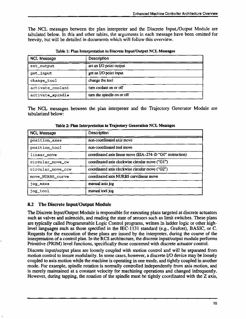
The NCL messages between the plan interpreter and the Discrete Input/Output Module aretabulated below. In this and other tables, the arguments in each message have been omitted forbrevity, but will be detailed in documents which will follow this overview .
Table 1: Plan Interpretation to Discrete Input/Output NCL Messages
Enhanced Machine Controller Architecture Overview
The NCL messages between the plan interpreter and the Trajectory Generator Module aretabularized below:
Table 2 : Plan Interpretation to Trajectory Generation NCL Messages
8.2 The Discrete Input/Output Module
The Discrete Input/Output Module is responsible for executing plans targeted at discrete actuatorssuch as valves and solenoids, and reading the state of sensors such as limit switches . These plansare typically called Programmable Logic Control programs, written in ladder logic or other high-level languages such as those specified in the IEC-1131 standard (e.g ., Grafcet), BASIC, or C.Requests for the execution of these plans are issued by the interpreter, during the course of theinterpretation of a control plan . In the RCS architecture, the discrete input/output module performsPrimitive (PRIM) level functions, specifically those concerned with discrete actuator control .Discrete input/output plans are loosely coupled with motion control and will be separated frommotion control to insure modularity . In some cases, however, a discrete I/O device may be looselycoupled to axis motion while the machine is operating in one mode, and tightly coupled in anothermode. For example, spindle rotation is normally controlled independently from axis motion, andis merely maintained at a constant velocity for machining operations and changed infrequently .However, during tapping, the rotation of the spindle must be tightly coordinated with the Z axis,
1 5
NCL Message Description
position-axes non-coordinated axis move
position-tool non-coordinated tool move
linear-move coordinated axis linear move (FIA-274-D "GO" instruction)
circular_move_cw coordinated axis clockwise circular move ("Gl")
circular move ccw coordinated axis clockwise circular move ("G2")
move NURBS curve coordinated axis NURBS curvilinear move
j og_axes manual axis jog
jog-tool manual tool jog
NCL Message Description
set output set an I/O point output
get_input get an I/O point input
change tool change the tool
activate coolant turn coolant on or offactivate-spindle turn the spindle on or off
Enhanced Machine Controller Architecture Overview
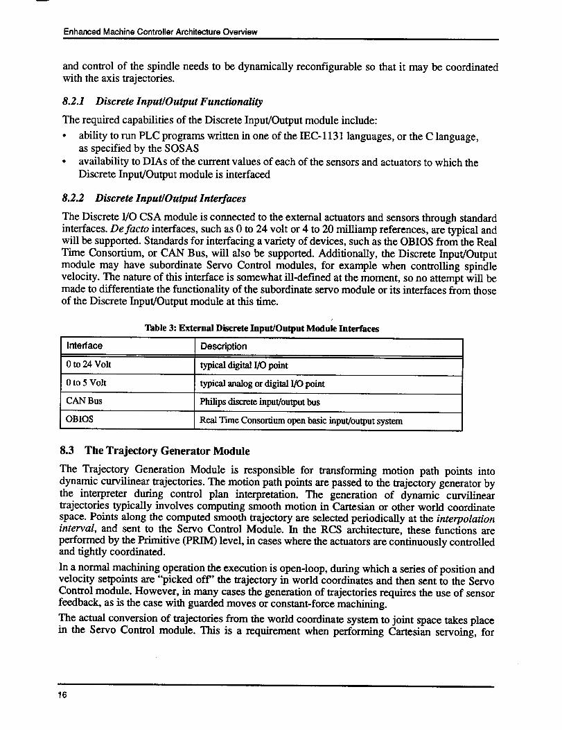
and control of the spindle needs to be dynamically reconfigurable so that it may be coordinatedwith the axis trajectories .
8.2.1 Discrete Input/Output Functionality
The required capabilities of the Discrete Input/Output module include :•
ability to run PLC programs written in one of the IEC-1131 languages, or the C language,as specified by the SOSAS
•
availability to DIAs of the current values of each of the sensors and actuators to which theDiscrete Input/Output module is interfaced
8.2.2 Discrete Input/Output Interfaces
The Discrete I/O CSA module is connected to the external actuators and sensors through standardinterfaces. De facto interfaces, such as 0 to 24 volt or 4 to 20 milliamp references, are typical andwill be supported . Standards for interfacing a variety of devices, such as the OBIOS from the RealTime Consortium, or CAN Bus, will also be supported . Additionally, the Discrete Input/Outputmodule may have subordinate Servo Control modules, for example when controlling spindlevelocity. The nature of this interface is somewhat ill-defined at the moment, so no attempt will bemade to differentiate the functionality of the subordinate servo module or its interfaces from thoseof the Discrete Input/Output module at this time .
Table 3 : External Discrete Input/Output Module Interfaces
16
8.3 The Trajectory Generator Module
The Trajectory Generation Module is responsible for transforming motion path points intodynamic curvilinear trajectories . The motion path points are passed to the trajectory generator bythe interpreter during control plan interpretation. The generation of dynamic curvilineartrajectories typically involves computing smooth motion in Cartesian or other world coordinatespace. Points along the computed smooth trajectory are selected periodically at the interpolationinterval, and sent to the Servo Control Module . In the RCS architecture, these functions areperformed by the Primitive (PRIM) level, in cases where the actuators are continuously controlledand tightly coordinated .In a normal machining operation the execution is open-loop, during which a series of position andvelocity setpoints are "picked off' the trajectory in world coordinates and then sent to the ServoControl module. However, in many cases the generation of trajectories requires the use of sensorfeedback, as is the case with guarded moves or constant-force machining .The actual conversion of trajectories from the world coordinate system to joint space takes placein the Servo Control module . This is a requirement when performing Cartesian servoing, for
Interface Description
0 to 24 Volt typical digital I/O point
0 to 5 Volt typical analog or digital I/O point
CAN Bus Philips discrete input/output bus
OBIOS Real Time Consortium open basic input/output system
example, in which servo computations are done in world coordinates . The responsibility formaking available the kinematics and Jacobian are thus placed upon the Servo Control module .
8.3.1 Trajectory Generation Module Functionality
The required capabilities of the Trajectory Generation module include :•
ability to plan and execute linear and circular trajectories•
the ability to extend the trajectory planning to handle trajectories defined with NURBS•
the ability to offset trajectories with transforms generated by sensor data•
availability to DIAs of the current world coordinate frame used for trajectory calculations•
availability to DIAs of the current position and velocity of the tool tip in the worldcoordinate frame
•
availability to DIAs of the timer semaphore which defines the interpolation interval
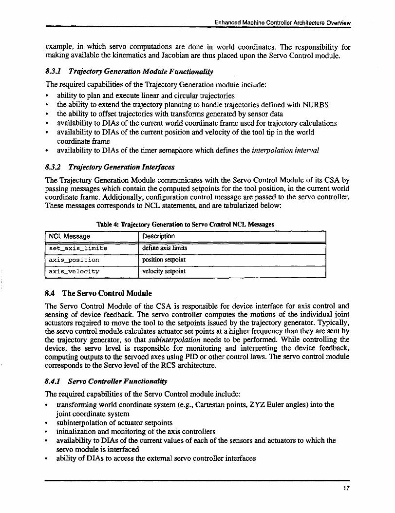
8.3.2 Trajectory Generation Interfaces
The Trajectory Generation Module communicates with the Servo Control Module of its CSA bypassing messages which contain the computed setpoints for the tool position, in the current worldcoordinate frame. Additionally, configuration control message are passed to the servo controller .These messages corresponds to NCL statements, and are tabularized below :
Table 4: Trajectory Generation to Servo Control NCL Messages
Enhanced Machine Controller Architecture Overview
8.4 The Servo Control Module
The Servo Control Module of the CSA is responsible for device interface for axis control andsensing of device feedback. The servo controller computes the motions of the individual jointactuators required to move the tool to the setpoints issued by the trajectory generator. Typically,the servo control module calculates actuator set points at a higher frequency than they are sent bythe trajectory generator, so that subinterpolation needs to be performed. While controlling thedevice, the servo level is responsible for monitoring and interpreting the device feedback,computing outputs to the servoed axes using PID or other control laws . The servo control modulecorresponds to the Servo level of the RCS architecture .
8.4.1 Servo Controller Functionality
The required capabilities of the Servo Control module include :•
transforming world coordinate system (e.g ., Cartesian points, ZYZ Euler angles) into thejoint coordinate system
•
subinterpolation of actuator setpoints•
initialization and monitoring of the axis controllers•
availability to DIAs of the current values of each of the sensors and actuators to which theservo module is interfaced
•
ability of DIAs to access the external servo controller interfaces
1 7
NCL Message Description
set-axis-limits define axis limits
axis-position position setpoint
axis-velocity velocity setpoint
Enhanced Machine Controller Architecture Overview
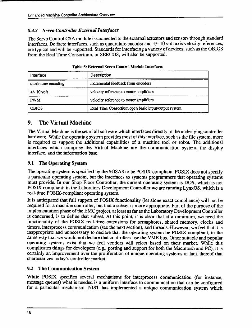
8.4.2 Servo Controller External Interfaces
The Servo Control CSA module is connected to the external actuators and sensors through standardinterfaces. De facto interfaces, such as quadrature encoder and +/- 10 volt axis velocity references,are typical and will be supported. Standards for interfacing a variety of devices, such as the OBIOSfrom the Real Time Consortium, or SERCOS, will also be supported .
liable 5: External Servo Control Module Interfaces
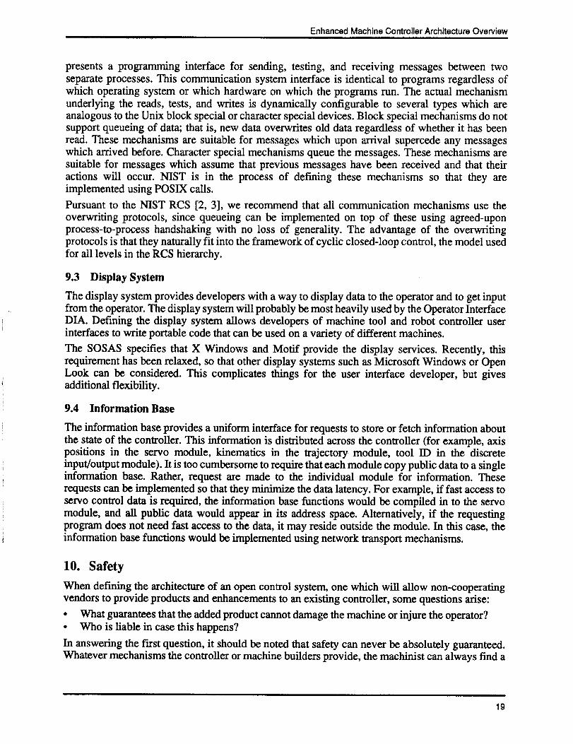
9. The Virtual MachineThe Virtual Machine is the set of all software which interfaces directly to the underlying controllerhardware. While the operating system provides most of this interface, such as the file system, moreis required to support the additional capabilities of a machine tool or robot . The additionalinterfaces which comprise the Virtual Machine are the communication system, the displayinterface, and the information base .
9.1 The Operating System
The operating system is specified by the SOSAS to be POSIX-compliant. POSIX does not specifya particular operating system, but the interfaces to systems programmers that operating systemsmust provide. In our Shop Floor Controller, the current operating system is DOS, which is notPOSIX compliant; in the Laboratory Development Controller we are running LynxOS, which is areal-time POSIX-compliant operating system .It is anticipated that full support of POSIX functionality (let alone exact compliance) will not berequired for a machine controller, but that a subset is more appropriate. Part of the purpose of theimplementation phase of the EMC project, at least as far as the Laboratory Development Controlleris concerned, is to define that subset . At this point, it is clear that at a minimum, we need thefunctionality of the POSIX real-time extensions for semaphores, shared memory, clocks andtimers, interprocess communication (see the next section), and threads . However, we feel that it isinappropriate and unnecessary to declare that the operating system be POSIX-compliant, in thesame way that we would not declare that controllers use the VME bus . Other suitable and popularoperating systems exist that we feel vendors will select based on their market . While thiscomplicates things for developers (e .g ., porting and support for both the Macintosh and PC), it iscertainly an improvement over the proliferation of unique operating systems or lack thereof thatcharacterizes today's controller market .
9.2 The Communication System
While POSIX specifies several mechanisms for interprocess communication (for instance,message queues) what is needed is a uniform interface to communication that can be configuredfor a particular mechanism. NIST has implemented a unique communication system which
1 8
Interface Description
quadrature encoding incremental feedback from encoders
+/- 10 volt velocity reference to motor amplifiers
PWM velocity reference to motor amplifiers
OBIOS Real Time Consortium open basic input/output system
Enhanced Machine Controller Architecture Overview
presents a programming interface for sending, testing, and receiving messages between twoseparate processes . This communication system interface is identical to programs regardless ofwhich operating system or which hardware on which the programs run . The actual mechanismunderlying the reads, tests, and writes is dynamically configurable to several types which areanalogous to the Unix block special or character special devices . Block special mechanisms do notsupport queueing of data; that is, new data overwrites old data regardless of whether it has beenread. These mechanisms are suitable for messages which upon arrival supercede any messageswhich arrived before . Character special mechanisms queue the messages . These mechanisms aresuitable for messages which assume that previous messages have been received and that theiractions will occur. NIST is in the process of defining these mechanisms so that they areimplemented using POSIX calls .Pursuant to the NIST RCS [2, 3], we recommend that all communication mechanisms use theoverwriting protocols, since queueing can be implemented on top of these using agreed-uponprocess-to-process handshaking with no loss of generality . The advantage of the overwritingprotocols is that they naturally fit into the framework of cyclic closed-loop control, the model usedfor all levels in the RCS hierarchy .
9.3 Display System
The display system provides developers with a way to display data to the operator and to get inputfrom the operator. The display system will probably be most heavily used by the Operator InterfaceDIA. Defining the display system allows developers of machine tool and robot controller userinterfaces to write portable code that can be used on a variety of different machines .The SOSAS specifies that X Windows and Motif provide the display services. Recently, thisrequirement has been relaxed, so that other display systems such as Microsoft Windows or OpenLook can be considered . This complicates things for the user interface developer, but givesadditional flexibility.
9.4 Information Base
The information base provides a uniform interface for requests to store or fetch information aboutthe state of the controller . This information is distributed across the controller (for example, axispositions in the servo module, kinematics in the trajectory module, tool ID in the discreteinput/output module). It is too cumbersome to require that each module copy public data to a singleinformation base. Rather, request are made to the individual module for information . Theserequests can be implemented so that they minimize the data latency. For example, if fast access toservo control data is required, the information base functions would be compiled in to the servomodule, and all public data would appear in its address space . Alternatively, if the requestingprogram does not need fast access to the data, it may reside outside the module. In this case, theinformation base functions would be implemented using network transport mechanisms .
10. SafetyWhen defining the architecture of an open control system, one which will allow non-cooperatingvendors to provide products and enhancements to an existing controller, some questions arise:•
What guarantees that the added product cannot damage the machine or injure the operator?•
Who is liable in case this happens?In answering the first question, it should be noted that safety can never be absolutely guaranteed .Whatever mechanisms the controller or machine builders provide, the machinist can always find a
1 9
Enhanced Machine Controller Architecture Overview
way to circumvent them . Limit switches which detect the removal of safety shields can be tapedshut by machinists. Dead man's switches can be clamped closed . Any protection in software isvulnerable to the same attacks used to override copy protection . Code developers can removenuisance safety mechanisms by simply overwriting the code with "no-ops," or null operations .Safety programs can simply fail to work due to insufficient testing . Processors executing the safetysoftware may fault, simultaneously causing a dangerous axis runaway condition while halting thesoftware which could check for this .A solution to these problems is to incorporate a "watchdog" safety system [8] into the controller,consisting of completely separate hardware which constantly monitors the activity of theworkstation and causes a complete but safe shutdown when any safety conditions are violated .Examples of conditions to be monitored include•
axes position, velocity, and acceleration•
tool speed•
cutter force•
engagement of safety shields•
servo following error•
motor current and torque•
hardware health signals ("heartbeats") of computers and equipment•
software health signals of processesWhen safety conditions are violated, the watchdog safety system opens the emergency stop loopcircuitry for a full stop of all systems which could potentially cause damage to the machine oroperator, such as axes, spindle, and tooling . The connection of these to the emergency stop loopmust be made so that they are not damaged when such a stop is made .The watchdog safety system must exist as a separate system which is not intended to be extensible .The conditions to be monitored should be set at limits which no reasonable machining operationwould ever exceed. Limits are only set by the OEM . The conditions must be available t -~ thewatchdog safety system in "raw" form, i.e., not after processing by the controller software .For example, axes position and velocity may be captured directly from encoders, scales, ortachometers, and fed to the safety system . Derived quantities such as acceleration must becomputed by the safety system, not the machine controller, by hardware or by software which issimple and correct in the software engineering sense .Health signals, or "heartbeats," should be provided by vital hardware (such as the CPU) in the formof continuously alternating signal levels, not absolute levels . The absence of alternation is anindication that the hardware has failed . Software processes (such as the looping of DiscreteInput/Output module processes) should generate hardware signals which also alternate in level toindicate health . The watchdog safety system can be equipped with missing pulse detectors totrigger a fault when these processes have failed to issue an alternating signal .
11. Road Map of Subsequent DocumentsThis document is an initial overview of the architecture that the EMC engineers will use as thereference for controller development. Machine controllers will be built which conform to thisreference model architecture . As a result of the implementation efforts, details of the standardizedapplications and modules will become clear, and will form the foundation of a second series ofdocuments. Listed below are each of the documents which will be issued, and a brief descriptionof their intended contents .
20
Enhanced Machine Controller Architecture Overview
Workstation Planning Standardized ApplicationThis document covers the WPSA, focusing on two areas : scheduling and programming .Scheduling will discuss how the workstation connects to the rest of the factory network, whatcommunication protocols are used (e.g ., MMS), and what is responsible for scheduling jobs in thefactory.
Workstation Management Standardized ApplicationThis covers the WMSA "engine," and details the minimum capabilities required for a controller tobe a controller. In this document we will discuss the modes and states of the controller .
Plan Interpretation ModuleHere will be detailed the planning languages (e.g., EIA-274-D, BCL, NCL), and how weimplemented extensibility, i.e., the ability to add a new G code to reflect the addition of NURBSprofiling in the trajectory generator . We will also detail the interfaces that allowed us to "swap" theplan interpretation module.
Discrete Input/Output ModulePLC languages will be detailed here, as will the messages that run PLC programs . IEC- 1131 willbe addressed in this document .
Trajectory Generation ModuleThe bulk of the trajectory generation module will derive from the more complex realm of five-axismilling and robotics.This is where we will detail the commands used to build a queue of motionprimitives, and what those primitives are . Extensibility will be demonstrated by adding NURBStrajectory generation to the weak set which is normally used now, namely straight lines and circles,and we'll tell how we did it. What we used to represent the machine's kinematic model, Jacobian,and other models will be spelled out .
Servo Control ModuleThis document will contain the list of all servo parameters we'll need, based on position controlbut with the flexibility to handle force and other physical quantities as well . Details of the errorcompensation methods we used (thermal/geometric, lead screw compensation tables, etc .) willappear in this volume . The hardware and software interfaces we defined which allow us to replacemotion control boards from one vendor with those of another will be written down .
Virtual MachineThe controller "infrastructure" will be laid out here . This includes the operating system, displaycapability, control panel interface, system variables, and events . How we handled different busesand CPUs will be detailed.
Domain Independent ApplicationsThe domain-independent applications include the operator interface, tool management, partprobing, and thermal compensation . The interfaces which each required will be documented, aswill the mechanism by which each was performed .
21
Enhanced Machine Controller Architecture Overview
12. References1 . The Martin Marietta Corporation, Next Generation Workstation/Machine Controller
Specification for an Open System Architecture Standard (Draft), Volumes I through VI,Document No. NGC-0001-13-000-SYS, March 1992 .
2 . Albus, J . S ., "RCS : A Reference Model Architecture for Intelligent Control," IEEE Journalon Computer Architectures for Intelligent Machines, May 1992.
3 . Albus, J. S., Lumia, R., Fiala, J. C., and Wavering, A. J., "NASREM: The NASA/NBSStandard Reference Model for Telerobot Control System Architecture," Proceedings of the20th International Symposium on Industrial Robots, Tokyo, Japan, October 4-6, 1989 .
4. POSIX (Portable Ouerating System Interface), FIPS Publication 151-1 .5 . Simpson, J., Hocken, R., and Albus, J., "The Automated Manufacturing Research Facility of
the National Bureau of Standards," Journal of Manufacturing Systems 1 (1), 1983 .6 . Kramer, T., "Process Planning for a Milling Machine from a Feature-Based Design,"
Proceedings of Manufacturing International, Atlanta, Georgia, April 1988, ASME, Vol . III,pp. 179-189, 1988 .
7 . National Computer Graphics Association, IGES/PDESOrganization Reference Manual,January 1993. NCGA: 2722 Merrilee Drive, Suite 200, Fairfax, VA 22031 .
8 . R. D. Kilmer, H. G. McCain, M. Juberts and S . A. Legowik, "Safety Computer Design andImplementation," International Trends in Manufacturing Technology : Robot Safety, IFS(Publications) Ltd., Springer-Verlag, Berlin, 1985 .
22